Generating LVDS Signals LVDS · LVDS Splitter 4111 The LVDS Splitter has five connectors, which are...
4
LVDS Splitter, Multiplexer, Frame Grabber, Frame Generator
Transcript of Generating LVDS Signals LVDS · LVDS Splitter 4111 The LVDS Splitter has five connectors, which are...
[email protected] [email protected] [email protected] [email protected]
Authorised Distributor:GOEPEL electronic GmbH
Goeschwitzer Straße 58 / 60
07745 Jena / Germany
Tel: + 49 (0) - 36 41 - 68 96 - 0
Fax: + 49 (0) - 36 41 - 68 96 - 944
Email: [email protected]
Internet: www.goepel.comISO 9001 certified
LV / E / 092010
LVDSSplitter, Multiplexer, Frame Grabber, Frame Generator
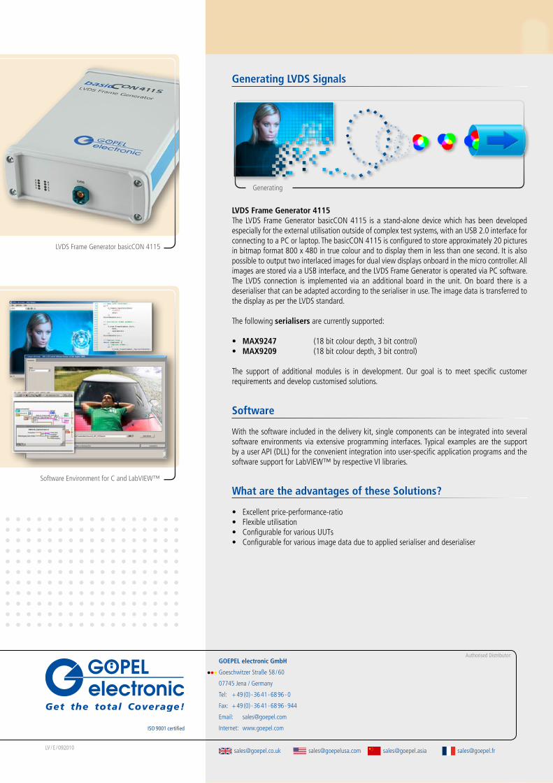
LVDS Frame Generator basicCON 4115
Software Environment for C and LabVIEW™
Generating LVDS Signals
LVDS Frame Generator 4115The LVDS Frame Generator basicCON 4115 is a stand-alone device which has been developed especially for the external utilisation outside of complex test systems, with an USB 2.0 interface for connecting to a PC or laptop. The basicCON 4115 is configured to store approximately 20 pictures in bitmap format 800 x 480 in true colour and to display them in less than one second. It is also possible to output two interlaced images for dual view displays onboard in the micro controller. All images are stored via a USB interface, and the LVDS Frame Generator is operated via PC software. The LVDS connection is implemented via an additional board in the unit. On board there is a deserialiser that can be adapted according to the serialiser in use. The image data is transferred to the display as per the LVDS standard.
The following serialisers are currently supported:
• MAX9247 (18 bit colour depth, 3 bit control)• MAX9209 (18 bit colour depth, 3 bit control)
The support of additional modules is in development. Our goal is to meet specific customer requirements and develop customised solutions.
Software
With the software included in the delivery kit, single components can be integrated into several software environments via extensive programming interfaces. Typical examples are the support by a user API (DLL) for the convenient integration into user-specific application programs and the software support for LabVIEW™ by respective VI libraries.
What are the advantages of these Solutions?
• Excellent price-performance-ratio• Flexible utilisation• Configurable for various UUTs• Configurable for various image data due to applied serialiser and deserialiser
Generating
LVDS Multiplexers PXI 4110 & basicCON 4110
Exchangeable Deserialiser in open system
LVDS Frame Grabbers basicCON 4120 & USB 4120
LVDS Splitter PXI 4111 & basicCON 4111
LVDS Splitter basicCON 4105
What is LVDS?
Low Voltage Differential Signaling is an interface standard for high-speed data transfer compliant with ANSI / TIA / EIA-644-1995. The standard describes a physical layer, not the applied protocols. The achievable data rate reaches several Gbps.
What can it be used for?The provision of information on displays is typical for communication between human beings and machines. With limitations on space at the display head is often necessary to have the display remote from the character generator. The distances between character generator and display head must be bridged. The LVDS standard provides for a simple electrical connection that provides
reliable wide bandwidth, high-speed digital signaling between subsystems that require large amounts of data to be transferred quickly.
LVDS interfaces can often be found in consumer products (cameras, DVD players etc.) and in automotive products. Important information for drivers, generated by various components within the vehicles, are visualised on displays. Due to its simple and robust structure, this sort of data connection can easily be integrated into vehicle technology where single ended signalling would fail.
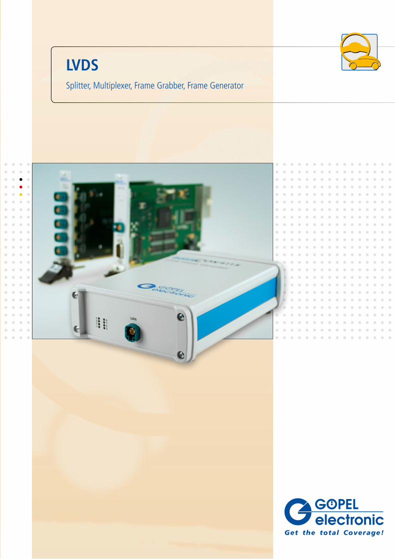
LVDS – what do we offer?
PXI Stand-Alone USB Rack
Splitter1:8 - basicCON 4105 -
1:4 PXI 4111 basicCON 4111 USB 4111
Multiplexer 4:1 PXI 4110 basicCON 4110 USB 4110
Frame Generator - basicCON 4115 -
Frame Grabber - basicCON 4120 USB 4120
Managing LVDS Signals
LVDS Splitter 4105The device allows the distribution of a LVDS signal to a maximum of eight receivers. It has been designed for the Bus-LVDS-SerDes (serialiser-deserialiser) concept, which means that a transfer of the entire video information including embedded clock pulse via only two wires is now possible. The eight outputs are identically constructed and active after power on.
LVDS Splitter 4111The LVDS Splitter has five connectors, which are designed in an array of one to four. It allows the LVDS signal distribution to four participants. Using this device, an LVDS compliant source may be connected to one of the four outputs. Active sold state switching and not common relays are used for signal routing providing both better isolation and signal conditioning (signal regeneration). Users can select a connection by means of external control equipment. A typical application for the 4111 splitter is a test setup for LCD monitors, e. g. if LVDS signals are distributed from one data source to four monitors.
Splitting Multiplexing / Demultiplexing
Managing LVDS Signals (continued)
LVDS Multiplexer 4110The LVDS Multiplexer has five connectors, which are configurable as an array of one to four or four to one. It allows the multiplexing and demultiplexing of an LVDS signal among these five participants. Active solid state switching and not common relays are used for signal routing providing both better isolation and signal conditioning (signal regeneration).
Analysing LVDS Signals
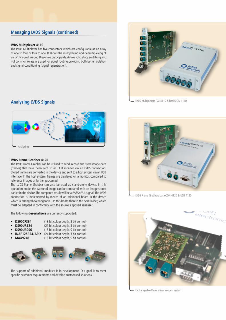
LVDS Frame Grabber 4120The LVDS Frame Grabber can be utilised to send, record and store image data (frames) that have been sent to an LCD monitor via an LVDS connection. Stored frames are converted in the device and sent to a host system via an USB interface. In the host system, frames are displayed on a monitor, compared to reference images or further processed.The LVDS Frame Grabber can also be used as stand-alone device. In this operation mode, the captured image can be compared with an image stored earlier in the device. The compared result will be a PASS / FAIL signal. The LVDS connection is implemented by means of an additional board in the device which is arranged exchangeable. On this board there is the deserialiser, which must be adapted in conformity with the source‘s applied serialiser.
The following deserialisers are currently supported:
• DS90CF364 (18 bit colour depth, 3 bit control)• DS90UR124 (21 bit colour depth, 3 bit control)• DS90UR906 (18 bit colour depth, 9 bit control)• INAP125R24 / APIX (24 bit colour depth, 3 bit control)• MAX9248 (18 bit colour depth, 9 bit control)
The support of additional modules is in development. Our goal is to meet specific customer requirements and develop customised solutions.
Analysing
LVDS Multiplexers PXI 4110 & basicCON 4110
Exchangeable Deserialiser in open system
LVDS Frame Grabbers basicCON 4120 & USB 4120
LVDS Splitter PXI 4111 & basicCON 4111
LVDS Splitter basicCON 4105
What is LVDS?
Low Voltage Differential Signaling is an interface standard for high-speed data transfer compliant with ANSI / TIA / EIA-644-1995. The standard describes a physical layer, not the applied protocols. The achievable data rate reaches several Gbps.
What can it be used for?The provision of information on displays is typical for communication between human beings and machines. With limitations on space at the display head is often necessary to have the display remote from the character generator. The distances between character generator and display head must be bridged. The LVDS standard provides for a simple electrical connection that provides
reliable wide bandwidth, high speed signaling between subsystems that require large amounts of data to be transferred quickly.
LVDS interfaces can often be found in consumer products (cameras, DVD players etc.) and in automotive products. Important information for drivers, generated by various components within the vehicles, are visualised on displays. Due to its simple and robust structure, this sort of data connection can easily be integrated into vehicle technology where single ended signalling would fail.
LVDS – what do we offer?
PXI Stand-Alone USB Rack
Splitter1:8 - basicCON 4105 -
1:4 PXI 4111 basicCON 4111 USB 4111
Multiplexer 4:1 PXI 4110 basicCON 4110 USB 4110
Frame Generator - basicCON 4115 -
Frame Grabber - basicCON 4120 USB 4120
Managing LVDS Signals
LVDS Splitter 4105The device allows the distribution of a LVDS signal to a maximum of eight receivers. It has been designed for the Bus-LVDS-SerDes (serialiser-deserialiser) concept, which means that a transfer of the entire video information including embedded clock pulse via only two wires is now possible. The eight outputs are identically constructed and active after power on.
LVDS Splitter 4111The LVDS Splitter has five connectors, which are designed in an array of one to four. It allows the LVDS signal distribution to four participants. Using this device, an LVDS compliant source may be connected to one of the four outputs. Active sold state switching and not common relays are used for signal routing providing both better isolation and signal conditioning (signal regeneration). Users can select a connection by means of external control equipment. A typical application for the 4105 splitter is a test setup for LCD monitors, e. g. if LVDS signals are distributed from one data source to four monitors.
Splitting Multiplexing / Demultiplexing
Managing LVDS Signals (continued)
LVDS Multiplexer 4110The LVDS Multiplexer has five connectors, which are configurable as an array of one to four or four to one. It allows the multiplexing and demultiplexing of an LVDS signal among these five participants. Active solid state switching and not common relays are used for signal routing providing both better isolation and signal conditioning (signal regeneration).
Analysing LVDS Signals
LVDS Frame Grabber 4120The LVDS Frame Grabber can be utilised to send, record and store image data (frames) that have been sent to an LCD monitor via an LVDS connection. Stored frames are converted in the device and sent to a host system via an USB interface. In the host system, frames are displayed on a monitor, compared to reference images or further processed.The LVDS Frame Grabber can also be used as stand-alone device. In this operation mode, the captured image can be compared with an image stored earlier in the device. The compared result will be a PASS / FAIL signal. The LVDS connection is implemented by means of an additional board in the device which is arranged exchangeable. On this board there is the deserialiser, which must be adapted in conformity with the source‘s applied serialiser.
The following deserialisers are currently supported:
• DS90CF364 (18 bit colour depth, 3 bit control)• DS90UR124 (21 bit colour depth, 3 bit control)• DS90UR906 (18 bit colour depth, 9 bit control)• INAP125R24 / APIX (24 bit colour depth, 3 bit control)• MAX9248 (18 bit colour depth, 9 bit control)
The support of additional modules is in development. Our goal is to meet specific customer requirements and develop customised solutions.
Analysing
[email protected] [email protected] [email protected] [email protected]
Authorised Distributor:GOEPEL electronic GmbH
Goeschwitzer Straße 58 / 60
07745 Jena / Germany
Tel: + 49 (0) - 36 41 - 68 96 - 0
Fax: + 49 (0) - 36 41 - 68 96 - 944
Email: [email protected]
Internet: www.goepel.comISO 9001 certified
LV / E / 092010
LVDSSplitter, Multiplexer, Frame Grabber, Frame Generator
LVDS Frame Generator basicCON 4115
Software Environment for C and LabVIEW™
Generating LVDS Signals
LVDS Frame Generator 4115The LVDS Frame Generator basicCON 4115 is a stand-alone device which has been developed especially for the external utilisation outside of complex test systems, with an USB 2.0 interface for connecting to a PC or laptop. The basicCON 4115 is configured to store approximately 20 pictures in bitmap format 800 x 480 in true colour and to display them in less than one second. It is also possible to output two interlaced images for dual view displays onboard in the micro controller. All images are stored via a USB interface, and the LVDS Frame Generator is operated via PC software. The LVDS connection is implemented via an additional board in the unit. On board there is a deserialiser that can be adapted according to the serialiser in use. The image data is transferred to the display as per the LVDS standard.
The following serialisers are currently supported:
• MAX9247 (18 bit colour depth, 3 bit control)• MAX9209 (18 bit colour depth, 3 bit control)
The support of additional modules is in development. Our goal is to meet specific customer requirements and develop customised solutions.
Software
With the software included in the delivery kit, single components can be integrated into several software environments via extensive programming interfaces. Typical examples are the support by a user API (DLL) for the convenient integration into user-specific application programs and the software support for LabVIEW™ by respective VI libraries.
What are the advantages of these Solutions?
• Excellent price-performance-ratio• Flexible utilisation• Configurable for various UUTs• Configurable for various image data due to applied serialiser and deserialiser
Generating