Generating and Executing Multi-Exit Custom Instructions for an Adaptive Extensible Processor Hamid...
39
Generating and Executing Multi-Exit Custom Instructions for an Adaptive Extensible Processor Hamid Noori † , Farhad Mehdipour ‡ , Kazuaki Murakami † , Koji Inoue † , and Maziar Goudarzi † † Kyushu University, Japan ‡ AmirKabir University of Technology, Iran
-
Upload
zoe-morris -
Category
Documents
-
view
226 -
download
0
Transcript of Generating and Executing Multi-Exit Custom Instructions for an Adaptive Extensible Processor Hamid...

Generating and Executing Multi-Exit Custom Instructions for an Adaptive Extensible Processor
Hamid Noori†, Farhad Mehdipour‡, Kazuaki Murakami†, Koji Inoue†, and Maziar Goudarzi†
† Kyushu University, Japan‡ AmirKabir University of Technology, Iran

DATE’07@Nice, FranceKyushu University
Outline
Introduction Overview of ADEXOR Architecture Generating Multi-Exit Custom Instructions
(MECIs) Proposing an Architecture for the CRFU Experimental Results Conclusions and Future Work

DATE’07@Nice, FranceKyushu University
Introduction Motivation
Increase in manufacturing and NRE costs Increase in design and verification costs due to more
complexity Shorter time-to-market More required flexibility due to evolution of standards,
user requirements, supporting multiple applications and etc
Our proposed approach Generating custom instruction after chip-fabrication Proposing multi-exit custom instructions Proposing a reconfigurable functional unit with
conditional execution using a quantitative approach

DATE’07@Nice, FranceKyushu University
General Overview of ADEXOR Architecture
DEC/EXE Pipeline Registers
FU1 FU2 FU3 FU4 CRFU
Reg0 ……………………………………………..
Reg31
EXE/MEM Pipeline Registers
Counter
ConfigMemory
Counter
From decode stage
Triggered by mtc0
Triggered by mtc0
DATE’07@Nice, FranceKyushu University
General Overview of ADEXOR Architecture
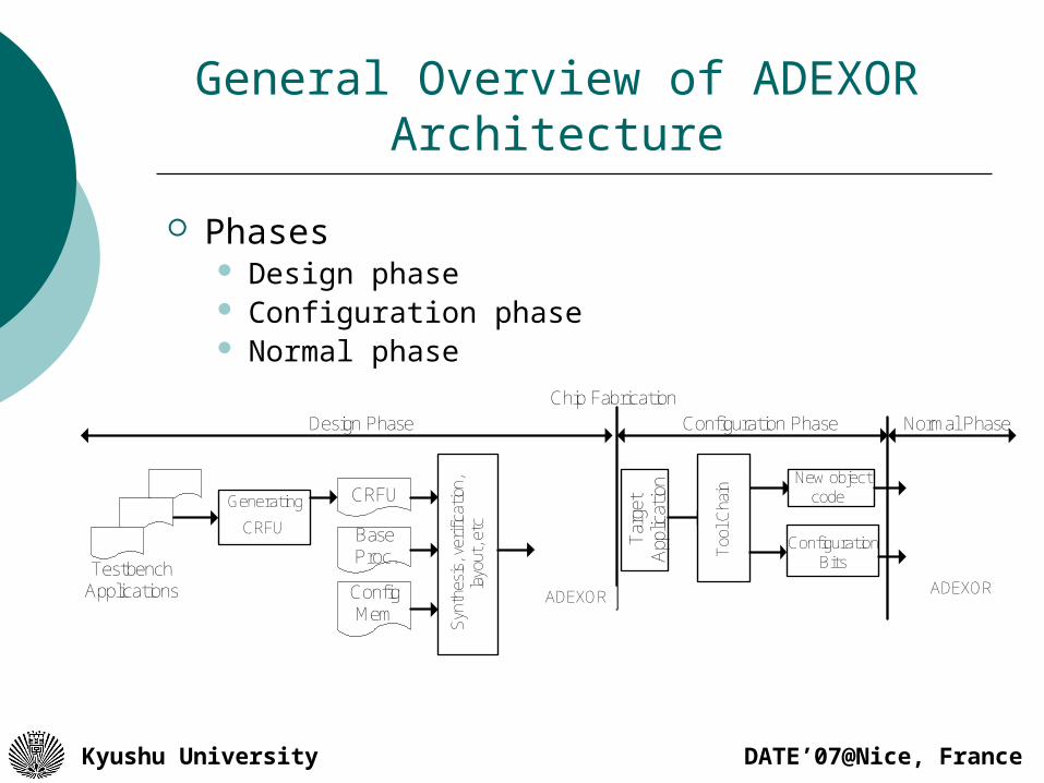
Phases Design phase Configuration phase Normal phase
Design PhaseChip Fabrication
TestbenchApplications
Generating
CRFU
Synt
hesi
s,ve
rific
atio
n,la
yout
,etc
ADEXOR
Targ
etApp
licat
ion New object
code
ConfigurationBits
Configuration Phase Normal Phase
CRFU
BaseProc.
ConfigMem
ADEXOR
Too
l Cha
in

DATE’07@Nice, FranceKyushu University
Generating Multi-Exit Custom Instructions
Multi-Exit Custom Instructions Include hot
directions of branch instructions
Include single entry but multiple exits

DATE’07@Nice, FranceKyushu University
Generating Multi-Exit Custom Instructions
Finding the largest sequence of instructions in the CFG Checking the anti-dependence and flow-dependence
and moving executable instructions to the head and tail(s) of MECIs
Rewriting the object code where instructions are going to be moved.
Detecting subgraphs in a HIS
branch
exit 1
LS
exit 2
S1
branch
exit 1
mtc1
branch
exit 1
Overwriting the entry node
with mtc1 instr
Moving instructions after checking data dependency (binary rewriting)
exit 2 exit 2
S2
S2
S1
S2
S1
LSLS

DATE’07@Nice, FranceKyushu University
Generating Multi-Exit Custom Instructions
Tool Chain
InstructionSet Simulator(Simplescalar)
ProfilerDetecting
Start Addressof HBBs
Reading HBBsfrom Object
code
Linking HBBs usingProfiling Informationand Generating HISs
GeneratingCDFG for
HISs
GeneratingMulti-Exit
InstructionsCustom
Updating CDFGand Binaryrewriting
(Partitioning andMapping MECIs)
IntegratedFramework

DATE’07@Nice, FranceKyushu University
CRFU Architecture: A Quantitative Approach
22 programs of MiBench were chosen Simplescalar toolset was utilized for simulation CRFU is a matrix of FUs
No of Inputs No of Outputs No of FUs Connections Location of Inputs & Outputs
Some definitions: Considering frequency and weight in measurement
CI Execution Frequency Weight (To equal number of executed instructions) Average = for all CIs (ΣFreq*Weight)
Rejection rate: Percentage of MECIs that could not be mapped on the CRFU
Mapping rate: Percentage of MECIs that could be mapped on the CRFU

DATE’07@Nice, FranceKyushu University
Inputs/Outputs
0
10
20
30
4050
60
70
80
90
100
1 2 3 4 5 6 7 8 9 10 11 12
Number of Inputs/Outputs
Ma
pp
ing
Ra
te
Inputs Outputs
`

DATE’07@Nice, FranceKyushu University
Functional Units
0
10
20
30
40
50
60
70
80
90
100
Number of FUs
Map
pin
g R
ate

DATE’07@Nice, FranceKyushu University
Width/Depth
0
10
20
30
40
50
60
70
80
90
100
1 2 3 4 5 6 7 8 9 10 11 12
Number of Width and Depth
Ma
pp
ing
Ra
teWidth without constraints Depth without constraintsWidth with constraints Depth with constraints

DATE’07@Nice, FranceKyushu University
CRFU Architecture
Connections from input ports toinputs of the rows
CRFU Input Ports
CRFU Output Ports
Outputs of 1st row to theinputs of 3rd, 4th and 5th rows
Outputs of 2nd row to theinputs of 4th and 5th rows
Row1
Row5
Adder/subtractor
AND OR XORBarrelShifter
Configurationbits
Configurationbits
Configurationbits
FU FU FU FU

DATE’07@Nice, FranceKyushu University
Supporting Conditional ExecutionFU1 FU2
FU3 FU4
ConfigurationBits
ConfigurationBits
Selector-Mux
DataSelection
Mux
Branch result from FU1
Branch result from FU2
Configuration Bits
Branch result from FU1
Branch result from FU2
Configuration Bits
Configuration Bits
Configuration Bits
DATE’07@Nice, FranceKyushu University
Synthesis result
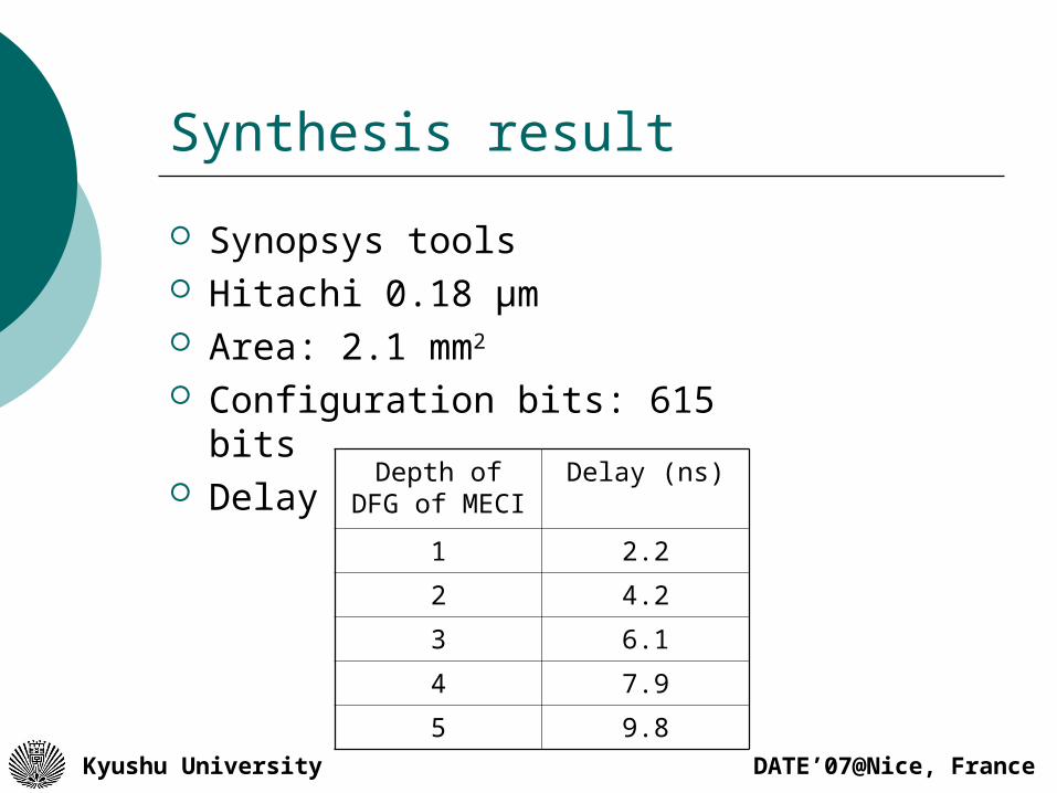
Synopsys tools Hitachi 0.18 μm Area: 2.1 mm2 Configuration bits: 615 bits Delay Depth of DFG
of MECIDelay (ns)
1 2.2
2 4.2
3 6.1
4 7.9
5 9.8

DATE’07@Nice, FranceKyushu University
Experiment setup
22 applications of Mibench Simplescalr
Issue 4-way
L1- I cache 32K, 2 way, 1 cycle latency
L1- D cache 32K, 4 way, 1 cycle latency
Unified L2 1M, 6 cycle latency
Execution units 4 integer, 4 floating point
RUU size & Fetch queue size 64
Branch predictor bimodal
Branch prediction table size 2048
Extra branch misprediction latency 3

DATE’07@Nice, FranceKyushu University
Speedup CIs & MECIs
1
1.2
1.4
1.6
1.8
2
2.2
2.4
2.6
2.8
3S
pee
du
p
CIs
MECIs

DATE’07@Nice, FranceKyushu University
Effect of clock frequency of speedup
1
1.5
2
2.5
3
3.5S
pe
ed
up
200 MHz 250 MHz 300 MHz 350 MHz 400 MHz

DATE’07@Nice, FranceKyushu University
Conclusion
Our experimental results show that by extending custom instructions over multiple HBBs the average speedup increases by 46% compared to the custom instructions which are limited to only one HBB. This is achieved in return for 83% more hardware and 20% more configuration bits. Utilizing connections with different length are helpful for supporting larger custom instructions with the available number of FUs.

DATE’07@Nice, FranceKyushu University
Future work
Energy evaluation of the ADEXOR Exploring the design space of CRFU
architecture (To study the effect of number of inputs, outputs, FU on the speedup, area and power)

DATE’07@Nice, FranceKyushu University
Thank you for your attention

DATE’07@Nice, FranceKyushu University
Introduction (1/2) Efficiency and flexibility in embedded system design
Both are critical Both are conflicting design goals Custom hardwired feature for more efficiency
(performance and energy) Programmable feature for more flexibility
Design challenges for future embedded systems More required efficiency (performance and
energy) for future embedded systems Higher manufacturing and NRE cost of new
nanometer-scale technologies Higher cost and risk in development Shorter time-to-market

DATE’07@Nice, FranceKyushu University
Introduction (2/2) Custom instructions
Effective technique for improving efficiency Custom functional units are required
(manufacturing, NRE and design cost)
Our proposed approach Generating custom instruction after chip-
fabrication Proposing multi-exit custom instructions Replacing custom functional units with a
reconfigurable functional unit with conditional execution

DATE’07@Nice, FranceKyushu University
Generating Multi-Exit Custom Instructions
Motivating example adpcm loop
B1
S1
B2
S2
B3
B4
S3
B5
S4
B6
S5
J1
B7
S6
J2
B8
B9
S7
B10
S8
S9
B11
J3
B12
S10
DATE’07@Nice, FranceKyushu University
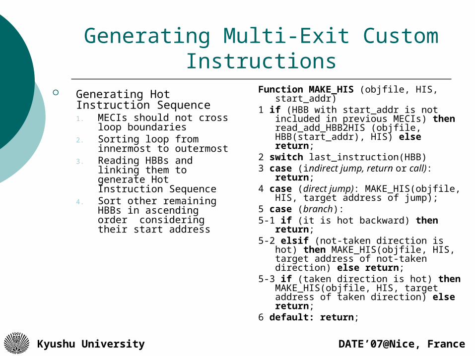
Generating Multi-Exit Custom Instructions Generating Hot Instruction
Sequence1. MECIs should not cross
loop boundaries2. Sorting loop from
innermost to outermost3. Reading HBBs and linking
them to generate Hot Instruction Sequence
4. Sort other remaining HBBs in ascending order considering their start address
Function MAKE_HIS (objfile, HIS, start_addr)
1 if (HBB with start_addr is not included in previous MECIs) then read_add_HBB2HIS (objfile, HBB(start_addr), HIS) else return;
2 switch last_instruction(HBB)3 case (indirect jump, return or call):
return; 4 case (direct jump): MAKE_HIS(objfile,
HIS, target address of jump); 5 case (branch): 5-1 if (it is hot backward) then return;5-2 elsif (not-taken direction is hot)
then MAKE_HIS(objfile, HIS, target address of not-taken direction) else return;
5-3 if (taken direction is hot) then MAKE_HIS(objfile, HIS, target address of taken direction) else return;
6 default: return;

DATE’07@Nice, FranceKyushu University
Generating Multi-Exit Custom Instructions
MECIs include fixed point instructions except multiply, divide and load. At most on store and five branches.
A MECI can have at most four exit points branch with only one hot direction indirect jump and return call hot backward branch an instruction where its next instruction is non-
executable. If both directions of a branch are hot, both
corresponding HBBs are added.

DATE’07@Nice, FranceKyushu University
Executing MECIs on the CRFU
DEC/EXE Pipeline Registers
FU1 FU2 FU3 FU4 CRFU
Reg0 ……………………………………………..
Reg31
EXE/MEM Pipeline Registers
Counter
ConfigMemory
Counter
From decode stage
Triggered by mtc0
Triggered by mtc0

DATE’07@Nice, FranceKyushu University
Proposing an Architecture for the CRFU
Design Methodology
First Stage
Mapping (MapToolP1) and AnalyzingCIs for Determining the CRFU
Preliminary Architecture
Generating HIS
Mapping is successful?
Mapping Process(MapToolP2)
Application
CustomInstructions (CIs)
CRFU PrimaryArchitecture
Mappable CIs(MapCIP2)
Rejected CIs
Integrated TemporalPartitioning & Mapping
(IntegFrameP3)
Fixing Final CRFUArchitecture
Yes
No
First Phase
Final CRFU Architecture
Third Phase
Fourth Phase
Object Code
HIS
Custom Instruction
1: SLL R2,R17,0x12: ADDU R2, R2,R173: SLL R2, R2, 0x34: ADDU R2, R2,R175: SLL R2,R2, 0x46: ADDU R2, R2,R207: SLL R3, R18, 0x28: ADDU R3, R3, R2
DFG
RFU Map ......
.
.
.. . .
5 6
7 1
2
4 3
1
2
3
4
5
6
8
7
8
DFG
RFU MapSecond Phase
Mappable CIs(MapCIP3)
Modifying Mapping Process(MapToolP4)
&
IntegFrameP4

DATE’07@Nice, FranceKyushu University
Mapping Tool
2
3
4
1
1: SUBU R3, R0, R32: ADDU R10, R0, R03: SRA R8, R10, 0x34: SLT R2, R3, R85: BNE R0,400488, R2
ADDU
SRA
SLT
SUBU
BNE
R3R0 R0R0
R10
R8
R2
R2
R30x3
400488
2
3
4
5
1
A Custom Instruction
Data Flow GraphRFU Map
5

DATE’07@Nice, FranceKyushu University
Integrated Framework (1/2)
Integrated Framework Performs an integrated
temporal partitioning and mapping process
Takes rejected CIs as input Partitions them to appropriate
mappable CIs Adds nodes to the current
partition while architectural constraints are satisfied
The ASAP level of nodes represents their order to execute according to their dependencies
Mapping onRFU
TemporalPartitioning
(HTTP or VTTP)
Mapping is successful?
FinalConfigurations
Incremental TemporalPartitioning
(HTTP or VTTP)NO
RFU ArchitecturalConstraints
Rejected CIs
YES
Similarity Detection
Spatial Merging
Reduced FinalConfigurations
IncrementalTemporal Partitions
TemporalPartitions (Initial
Partitions)
DATE’07@Nice, FranceKyushu University
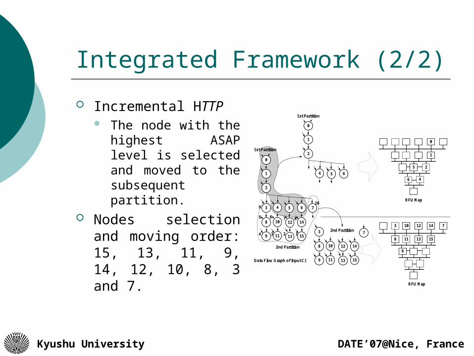
Integrated Framework (2/2)
Incremental HTTP The node with the
highest ASAP level is selected and moved to the subsequent partition.
Nodes selection and moving order: 15, 13, 11, 9, 14, 12, 10, 8, 3 and 7.
2
6 4
0
1
5
RFU Map
0
1
2
3
8
9
4
10
11
5
12
13
6
14
15
7
Data Flow Graph of Input CI
1st Partition
2nd Partition
0
1
2
4 5 6
7
1st Partition
3
8
9
10
11
12
13
14
15
2nd Partition123
5
4
6 7 8
9
3
11
10 12 14 7
8 13 15
9
RFU Map
10

DATE’07@Nice, FranceKyushu University
Supporting Conditional Execution
1 5 6 7 84 11 15
17 16212223242526
... ... ...
...
Control Dependencies
subu
slt
bne
sra
slt
sra
bne
8
16
17
15
21
22
23
19
5
subu
subusubu 7
Data Dependencies
Imm
DATE’07@Nice, FranceKyushu University
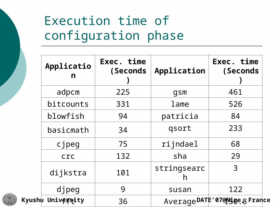
Execution time of configuration phase
ApplicationExec. time
(Seconds)Application
Exec. time (Seconds)
adpcm 225 gsm 461
bitcounts 331 lame 526
blowfish 94 patricia 84
basicmath 34 qsort 233
cjpeg 75 rijndael 68
crc 132 sha 29
dijkstra 101 stringsearch 3
djpeg 9 susan 122
fft 36 Average 150.8

DATE’07@Nice, FranceKyushu University
Effect of connections on mapping rate
By deleting the connections with length more than one, 24.2% of MECIs can not be mapped.
DATE’07@Nice, FranceKyushu University
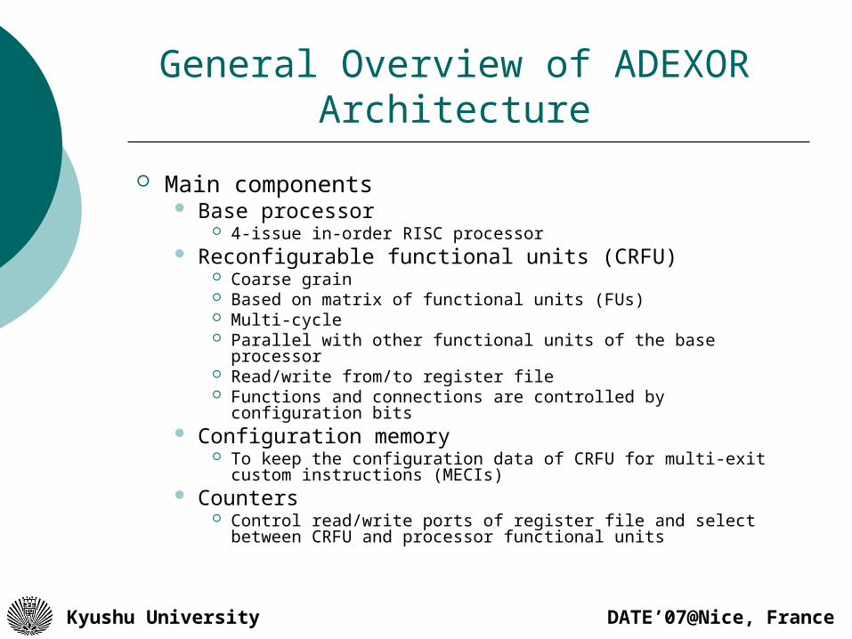
General Overview of ADEXOR Architecture
Main components Base processor
4-issue in-order RISC processor Reconfigurable functional units (CRFU)
Coarse grain Based on matrix of functional units (FUs) Multi-cycle Parallel with other functional units of the base processor Read/write from/to register file Functions and connections are controlled by configuration
bits Configuration memory
To keep the configuration data of CRFU for multi-exit custom instructions (MECIs)
Counters Control read/write ports of register file and select between
CRFU and processor functional units

DATE’07@Nice, FranceKyushu University
Speedup CIs & MECIs
The number of inputs, outputs and FUs are the same
simpler connections and FUs and does not support conditional execution.
Area: 1.15 mm2 Delay for a CI with a critical length of five is 7.66
ns. Each CI configuration needs 512 bits. The average number of instructions included in
CIs (one HBB) is 6.39 instructions and for MECIs is 7.85 instructions.

DATE’07@Nice, FranceKyushu University
MECIs vs. CI
0
20
40
60
80
100
120
140
160
180
%S
pe
ed
up
en
ha
nc
em
en
t
DATE’07@Nice, FranceKyushu University
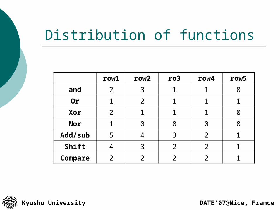
Distribution of functions
row1 row2 ro3 row4 row5
and 2 3 1 1 0
Or 1 2 1 1 1
Xor 2 1 1 1 0
Nor 1 0 0 0 0
Add/sub 5 4 3 2 1
Shift 4 3 2 2 1
Compare 2 2 2 2 1

DATE’07@Nice, FranceKyushu University
Control Bits & Immediate Data
375 bits are needed as Control Bits for Multiplexers Functional Units
240 bits are needed for Immediates Each CI configuration needs
(308+204 = 615 bits)