Generalized Frequency Division Multiplexing With Flexible...
20
SPECIAL SECTION ON INDEX MODULATION TECHNIQUES FOR NEXT-GENERATION WIRELESS NETWORKS Received September 28, 2017, accepted October 18, 2017, date of publication October 31, 2017, date of current version November 28, 2017. Digital Object Identifier 10.1109/ACCESS.2017.2768401 Generalized Frequency Division Multiplexing With Flexible Index Modulation ERSİN ÖZTÜRK 1,2 , ERTUGRUL BASAR 1 , (Senior Member, IEEE), AND HAKAN ALİ ÇIRPAN 1 , (Member, IEEE) 1 Faculty of Electrical and Electronics Engineering, Istanbul Technical University, 34469 Istanbul, Turkey 2 Netas Telecommunication, Department of Research and Development, 34912 Istanbul, Turkey Corresponding author: Ersin Öztürk ([email protected]) This work was partially supported by Netas Telecommunication. ABSTRACT After the vision and the overall objectives of future wireless networks for 2020 and beyond have been defined, standardization activities for fifth generation (5G) wireless networks have been started. Although it is expected that 5G new radio (NR) will be based on cyclicly prefixed orthogonal fre- quency division multiplexing (CP-OFDM)-based waveforms along with multiple waveform numerologies, the sufficiency of CP-OFDM-based NR is quite disputable due to the continuing massive growth trend in number of wireless devices and applications. Therefore, studies on novel radio access technologies (RATs) including advanced waveforms and more flexible radio accessing schemes must continue for future wireless networks. Generalized frequency division multiplexing (GFDM) is one of the prominent non-CP-OFDM- based waveforms. It has recently attracted significant attention in research because of its beneficial properties to fulfill the requirements of future wireless networks. Multiple-input multiple-output (MIMO)-friendliness is a key ability for a physical layer scheme to satisfactorily match the foreseen requirements of future wireless networks. On the other hand, the index modulation (IM) concept, which relies on conveying additional information bits through indices of certain transmit entities, is an emerging technique to pro- vide better spectral and energy efficiency. In this paper, considering the advantages of non-CP-OFDM- based waveforms and the IM concept, we present a framework, which integrates GFDM with space and frequency IM schemes to provide flexible and advanced novel RATs for future wireless networks. Several MIMO-GFDM schemes are provided through the proposed framework and their bit error ratio performances, computational complexities, and spectral efficiencies are analyzed. Based on the obtained results, a guideline for selecting the proper MIMO-GFDM scheme considering target performance criterion is given. It has been demonstrated that the proposed framework has a strong potential to engineer the space-frequency structure according to channel conditions and use cases, and it provides a great flexibility that can be easily tuned to address the required performance criterion. INDEX TERMS 5G wireless networks, GFDM, index modulation, MIMO systems, multicarrier modulation, physical layer design, quadrature spatial modulation, spatial modulation. I. INTRODUCTION Wireless communications has become an essential tool for our life. Starting from the first generation wireless net- works (1G), there has been an exponential growth in number of users and their applications. Owing to a broad range of applications spanning from wireless regional area networks to machine type communications, future wireless networks have challenging objectives such as very high spectral and energy efficiency, very low latency and very high data rate, which require more effective physical layer (PHY) solu- tions [1]. In this context, the vision and overall objectives of future wireless networks for 2020 and beyond have been defined by the International Telecommunication Union [2] and standardization activities for fifth generation (5G) wire- less networks have been started through discussions about scenarios and requirements by Third Generation Partnership Project (3GPP) [3]. Orthogonal frequency division multiplexing (OFDM) is the core of the physical layer of fourth generation (4G) wire- less networks and fulfills the requirements and challenges of 4G scenarios. Despite of its proven advantages, OFDM has some shortcomings that make it difficult to address the scenarios foreseen for future 5G wireless networks. In OFDM, every symbol requires a cyclic prefix (CP), which VOLUME 5, 2017 2169-3536 2017 IEEE. Translations and content mining are permitted for academic research only. Personal use is also permitted, but republication/redistribution requires IEEE permission. See http://www.ieee.org/publications_standards/publications/rights/index.html for more information. 24727
Transcript of Generalized Frequency Division Multiplexing With Flexible...
SPECIAL SECTION ON INDEX MODULATION TECHNIQUES FORNEXT-GENERATION WIRELESS NETWORKS
Received September 28, 2017, accepted October 18, 2017, date of publication October 31, 2017,date of current version November 28, 2017.
Digital Object Identifier 10.1109/ACCESS.2017.2768401
Generalized Frequency Division MultiplexingWith Flexible Index ModulationERSİN ÖZTÜRK 1,2, ERTUGRUL BASAR 1, (Senior Member, IEEE),AND HAKAN ALİ ÇIRPAN1, (Member, IEEE)1Faculty of Electrical and Electronics Engineering, Istanbul Technical University, 34469 Istanbul, Turkey2Netas Telecommunication, Department of Research and Development, 34912 Istanbul, Turkey
Corresponding author: Ersin Öztürk ([email protected])
This work was partially supported by Netas Telecommunication.
ABSTRACT After the vision and the overall objectives of future wireless networks for 2020 and beyondhave been defined, standardization activities for fifth generation (5G) wireless networks have been started.Although it is expected that 5G new radio (NR) will be based on cyclicly prefixed orthogonal fre-quency division multiplexing (CP-OFDM)-based waveforms along with multiple waveform numerologies,the sufficiency of CP-OFDM-based NR is quite disputable due to the continuing massive growth trend innumber of wireless devices and applications. Therefore, studies on novel radio access technologies (RATs)including advanced waveforms and more flexible radio accessing schemes must continue for future wirelessnetworks. Generalized frequency division multiplexing (GFDM) is one of the prominent non-CP-OFDM-based waveforms. It has recently attracted significant attention in research because of its beneficial propertiesto fulfill the requirements of future wireless networks. Multiple-input multiple-output (MIMO)-friendlinessis a key ability for a physical layer scheme to satisfactorily match the foreseen requirements of futurewireless networks. On the other hand, the index modulation (IM) concept, which relies on conveyingadditional information bits through indices of certain transmit entities, is an emerging technique to pro-vide better spectral and energy efficiency. In this paper, considering the advantages of non-CP-OFDM-based waveforms and the IM concept, we present a framework, which integrates GFDM with space andfrequency IM schemes to provide flexible and advanced novel RATs for future wireless networks. SeveralMIMO-GFDM schemes are provided through the proposed framework and their bit error ratio performances,computational complexities, and spectral efficiencies are analyzed. Based on the obtained results, a guidelinefor selecting the proper MIMO-GFDM scheme considering target performance criterion is given. It has beendemonstrated that the proposed framework has a strong potential to engineer the space-frequency structureaccording to channel conditions and use cases, and it provides a great flexibility that can be easily tuned toaddress the required performance criterion.
INDEX TERMS 5Gwireless networks, GFDM, indexmodulation,MIMO systems, multicarrier modulation,physical layer design, quadrature spatial modulation, spatial modulation.
I. INTRODUCTIONWireless communications has become an essential tool forour life. Starting from the first generation wireless net-works (1G), there has been an exponential growth in numberof users and their applications. Owing to a broad range ofapplications spanning from wireless regional area networksto machine type communications, future wireless networkshave challenging objectives such as very high spectral andenergy efficiency, very low latency and very high data rate,which require more effective physical layer (PHY) solu-tions [1]. In this context, the vision and overall objectivesof future wireless networks for 2020 and beyond have been
defined by the International Telecommunication Union [2]and standardization activities for fifth generation (5G) wire-less networks have been started through discussions aboutscenarios and requirements by Third Generation PartnershipProject (3GPP) [3].
Orthogonal frequency division multiplexing (OFDM) isthe core of the physical layer of fourth generation (4G) wire-less networks and fulfills the requirements and challengesof 4G scenarios. Despite of its proven advantages, OFDMhas some shortcomings that make it difficult to addressthe scenarios foreseen for future 5G wireless networks.In OFDM, every symbol requires a cyclic prefix (CP), which
VOLUME 5, 20172169-3536 2017 IEEE. Translations and content mining are permitted for academic research only.
Personal use is also permitted, but republication/redistribution requires IEEE permission.See http://www.ieee.org/publications_standards/publications/rights/index.html for more information.
24727

E. ÖZTÜRK et al.: GFDM With FIM
depends on the tap length of the channel. The insertion of CPreduces the spectral efficiency and prevents obtaining a lowlatency by shortening the symbols. Furthermore, OFDM isvery sensitive to time and frequency synchronization errorsand has high out-of-band (OOB) emission due to rectangu-lar pulse shaping. Thus, OFDM can fulfill the requirementsof 5G wireless networks in a limited way.
In recent years, several waveform proposals have beenpresented to overcome the above limitations of OFDM. Theseproposals can be categorized into two main classes: cyclicly-prefixed OFDM (CP-OFDM)-based and non-CP-OFDM-based. The proposals in the first class, such as filtered OFDM(f-OFDM) [4], [5] and windowed OFDM (W-OFDM) [6],are the attempts to resolve the aforementioned problems bykeeping the orthogonality. The proposals in the second classinitially dismiss orthogonality to obtain better temporal andspectral characteristics, thus, causes a major paradigm shiftin the context of waveform design, which may yield somebackward compatibility issues.
Generalized frequency division multiplexing (GFDM) [7]is one of the prominent non-CP-OFDM-based waveforms.It has recently attracted significant attention from theresearchers because of its beneficial properties to fulfill therequirements of future wireless networks. A GFDM symbolconsists KM samples where each of K subcarriers carryM timeslots. These parameters can be tuned to match therequirements of the application. Consequently, GFDM has aflexibility to engineer the time-frequency structure accord-ing to corresponding scenario. In GFDM, each subcarrier isfiltered using circular convolution. Therefore, OOB emissionof GFDM is considerably low and it can serve for fragmentedand opportunistic spectrum allocation purposes. GFDM usesa single CP for an entire block that contains multiple sub-symbols. This enables frequency domain equalization (FDE)and improves the spectral efficiency. Thus, flexible charac-teristics of GFDM can be easily tuned to address the newrequirements.
Multiple-input multiple-output (MIMO)-friendliness is akey ability for a physical layer scheme to satisfactorilymatch the foreseen requirements of future wireless networks.Since GFDM is a generalized form of OFDM, one canexpect that its combination with MIMO is feasible. Thiswas shown for space-time coding (STC) technique [7]–[10]and spatial multiplexing [11]–[17]. In [11] and [12],iterative MIMO decoders have been evaluated. In [13],separate detection and demodulation (SDD) with minimummean squared error (MMSE) detector and zero-forcing (ZF)GFDM demodulation was proposed. In [14], an equivalentMIMO-GFDM channel model, which combines GFDMmodulation and MIMO channel, has been presented andsphere decoding (SD) of subcarrier groups with successiveinterference cancellation (SIC) was proposed. Based onthis equivalent MIMO channel model, MMSE with parallelinterference cancellation (MMSE-PIC) detector was pro-posed in [15] and coded performance analysis ofMIMO-GFDM system was performed in [16]. In [17], a low
complexity implementation of MMSE equalization wasproposed and link level performance of MIMO-GFDMwas analyzed along with the CP-OFDM-based counterparts.Nevertheless, when spatial multiplexing is employed withGFDM, inter-antenna interference (IAI) is added to inherentself-interference of GFDM and makes the receiver designchallenging.
The continuing demand for higher data rates motivatesthe researchers to seek spectrally efficient new modulationschemes. Spatial modulation (SM) is a MIMO transmissionmethod, which considers the transmit antennas as spatialconstellation points to carry additional information bits [18].In SM, at each time interval, a single transmit antenna isactivated by the input bit sequences and other antennasremain silent. For SMmulticarrier schemes, only one transmitantenna is activated at any subcarrier. As a result, activatingsingle transmit antenna at a time or subcarrier eliminates IAIand reduces the receiver complexity. Moreover, SM tech-niques are more robust to channel imperfections and enhancethe error performance.
SM-based modulation schemes have recently receiveda great deal of interest due to their attractive advantagesover classical MIMO systems. Space-shift keying (SSK) isa special case of SM, where only active transmit antennaindices are used to convey information. In SSK, phase shiftkeying (PSK)/quadrature amplitudemodulation (QAM) sym-bols are not used and active transmit antenna transmits a fixednon-data bearing signal. Space-time shift keying (STSK)is another SM-based modulation scheme, where both theindices of multiple pre-assigned dispersion matrices andsignal constellation points are used to convey information.Additionally, the concept of SM is extended to include boththe space and time dimensions. Quadrature SM (QSM) [19]expands the spatial constellation symbols to in-phase andquadrature components, and doubles the number of spa-tially carried bits with respect to a conventional SM system.In QSM, signal constellation symbol is divided into its realand imaginary parts and their corresponding transmit anten-nas are determined by the input bit sequences in a separatefashion. It is demonstrated that QSM achieves the same errorperformance and spectral efficiency using 3 dB less signalpower with respect to its SM counterpart without increasingthe receiver complexity [19].
OFDM with index modulation (IM) is an extension ofspatial modulation concept to subcarrier indices in multi-carrier systems [20]–[22]. In OFDM-IM, active subcarriersare selected by the input bit sequences and the informa-tion bits are conveyed through both the activated subcarrierindices and the conventional modulation symbols. WhileOFDM-IM scheme improves the error performance by con-veying extra information through active subcarrier indices,it reduces throughput due to unused subcarriers. In [23],a dual-mode (DM) OFDM-IM (DM-OFDM) scheme hasbeen proposed to prevent throughput loss still using sub-carrier indices to convey extra information. In DM-OFDMscheme, based on the OFDM subblocks concept in [20],
24728 VOLUME 5, 2017
E. ÖZTÜRK et al.: GFDM With FIM
two different constellation modes have been used to mod-ulate the subcarriers with selected indices and the remain-ing subcarriers. More recently, a multiple-mode DM-OFDMscheme is proposed in [24] by considering full permutationof modes. In order to improve the spectral efficiency, diver-sity and coding gains of OFDM-IM, several studies havebeen also performed in recent times [25]–[29]. Furthermore,in [30]–[33], combination of the OFDM-IM technique withMIMO methods has been investigated and significant per-formance gains have been reported. For a comprehensiveoverview of OFDM-IM and related literature, interested read-ers are referred to [34].
Although 3GPP embraces a non-backward compatibleradio access technology (RAT) for 5G [35], it is expectedthat 5G new radio (NR) will be based on CP-OFDM-based waveforms along with the multiple OFDM numerolo-gies due to complexity, latency and maturity issues ofnon-CP-OFDM-based waveforms. However, considering thecontinuing massive growth trend in number of wirelessdevices and applications, the sufficiency of CP-OFDM-basedNR is quite disputable. Thus, research efforts on the novelRATs including advanced waveforms and more flexibleradio accessing schemes must continue for future wirelessnetworks. In this context, more advanced parameterizationschemes in numerology design, e.g., numerology with newparameters such as windowing and user-specific filters, andnovel frame design principles, e.g., frame design with multi-ple base waveforms, are proposed in [36]. In addition to theseproposals, non-CP-OFDM-based waveforms along with thepromising schemes, such as IM, are one of the prominentconcepts to enhance the RAT flexibility.
Non-CP-OFDM-based waveform proposals suffer fromself-introduced interference, which eventually results muchincreased receiver complexity especially for MIMO trans-mission due to additional IAI. Keeping mind the appealingadvantages of the IM concept over classical OFDM, suchas flexible system design with adjustable number of activesubcarriers, improved error performance for low-to-mid spec-tral efficiencies and simple transceiver design, we believethat tight integration of GFDM with the IM concept has astrong potential to fulfill the foreseen requirements of futurewireless networks in a satisfactory manner. In this context,the application of the SM-GFDM system has been consideredin [37], where due to the use of a suboptimal receiver, a poorerror performance has been obtained. In addition, the combi-nation of the IM technique [38] with GFDM has been inves-tigated in [39], where a throughput loss was obtained due tothe unused subcarriers. Furthermore, combination of GFDMwith SM and IM techniques, namely space and frequencyIM (SFIM), has been investigated in [40] and significantperformance gains have been achieved at the expense ofincreased computational complexity. As a result, the exist-ing studies on the integration of GFDM with promisingIM techniques are not satisfactory to improve the spectralefficiency as well as the error performance and computationalcomplexity at the same time.
In this paper, a framework that comprise the existingstudies on the combination of GFDM with IM concept ispresented and integration of GFDM with IM concept is dis-cussed in detail to pave the way for innovative transceiverstructures. Then, by using this framework, novel transmitterand receiver schemes for MIMO-GFDM applications areproposed. Bit error ratio (BER) performances of the proposedschemes are compared and their computational complexitiesand spectral efficiencies are analyzed. Based on the obtainedresults, a guideline for selecting the proper MIMO-GFDMscheme considering target performance criterion is given. Thecontributions of this paper can be summarized as follows:• A GFDM-based flexible IM (FIM) transceiver, which iscapable of generating and decoding various IM schemes,is proposed. Thanks to FIM, switching between differentIM schemes to adapt the channel conditions can bepossible using a single transceiver structure.
• FIM provides a multilayer transmission scheme byeffectively using space, frequency, and time dimensionsto adjust the BER performance and spectral efficiency,and enables to support different use-cases by using com-mon space, frequency, and time resources at the sametime.
• A novel QSM-based GFDM scheme is proposed asa special case of FIM to enhance the spectral effi-ciency while preserving the advantages of SM. To thebest of our knowledge, this contribution would be thefirst approach that exploits multicarrier transmission forQSM. In addition, QSM transmission is combined withthe SFIM scheme.
• A near-optimum detection scheme, which is basedon maximum likelihood (ML) detection with SIC, isproposed.
• It is shown that ML-SIC detection scheme is also appli-cable for single-input single-output (SISO), SM, IM,SFIM, and SSK-based GFDM systems.
The remaining sections are organized as follows. Thesystem models of the GFDM-FIM transmitter and receiverare presented in Section II and Section III, respectively.In Sections IV and V, computational complexity and spectralefficiency of the proposed GFDM-FIM schemes are ana-lyzed. Numerical results about the BER performance, com-putational complexity and spectral efficiency of the proposedGFDM-FIM schemes are presented in Section VI and dis-cussed in Section VII. Finally, Section VIII concludes thepaper.1
1Notation: Vectors and matrices are denoted by boldface lowercase andcapital letters, respectively. (·)T and (·)H denote transposition and Hermitiantransposition of a vector or a matrix, respectively, and (·)−1 indicates theinverse of a matrix. C(u, v) denotes the binomial coefficient and b·c is thefloor function. X ∼ CN (0, σ 2X ) represents the distribution of a circularlysymmetric complexGaussian random variableX with variance σ 2X .<{X} and={X} denote the real and imaginary parts of a complex variable X , respec-tively. diag(·) denotes a diagonal matrix and ‖·‖ stands for the Euclideannorm. S denotes Q-ary signal constellation and x(a : b) stands for allelements of x between ath and bth indices, inclusive of a and b.
VOLUME 5, 2017 24729

E. ÖZTÜRK et al.: GFDM With FIM
FIGURE 1. Block diagram of the GFDM-FIM transmitter.
TABLE 1. System parameters.
II. GFDM-FIM TRANSMITTERAs mentioned earlier, GFDM has a block structure consistingofN = KM samples whereK subcarriers constitute a GFDMsubsymbol and M GFDM subsymbols constitute a GFDMsymbol. In this study, a MIMO-GFDM system with T trans-mit and R receive antennas is considered. The system has fourcontrol signals named as ENSM , ENQM , ENIM , and ENDM ,which control SM, QSM, IM, and dual mode IM (DMIM)operation modes, respectively, in an on/off fashion, whereENSM , ENQM , ENIM , ENDM ∈ {0, 1}. The overall systemparameters are given in Table 1. Specific implementations ofSM and IM schemes with respect to control signals are givenin Table 2. Thanks to these control signals, existing schemes,such as, GFDM-based IM, DMIM, SM, and SFIM and newSM and IM schemes, such as, GFDM based QSM, space and
TABLE 2. Flexible IM control table.
frequency DMIM (SFDMIM), quadrature SFIM (QSFIM)and quadrature SFDMIM (QSFDMIM) can be implementedby using a single transmitter.
The block diagram of the proposed GFDM-FIM transmit-ter is given in Fig. 1. Primary bit splitter block accepts P databits from the input bit stream along with the control signalsand splits these P bits into L groups with p bits, i.e., p = P/L.Then, each group of p bits is mapped to a subcarriergroup with u elements in three stages. In this mappingoperation, antenna and subcarrier indices as well as Q-aryQAM (Q-QAM) constellations can be used. Besides, constel-lation symbols can be expanded to in-phase and quadraturecomponents. In order to apply this mapping, secondary bitsplitter partitions these p bits into four groups, which containpT , pIM , pA, and pB bits according to status of the controlsignals.
The first stage of themapping is transmit antenna selection.At this stage, Tx antenna selector block gets
pT = ENSM (1+ ENQM ) log2(T ) (1)
24730 VOLUME 5, 2017
E. ÖZTÜRK et al.: GFDM With FIM
bits and selects the indices of the transmit antennas. Whenboth SM and QSM modes are enabled, i.e., ENSM = 1,ENQM = 1, the first and second log2(T )-bits parts of thepT -bit sequence are used to determine the transmit antennascorresponding to the real and the imaginary parts of the vectorof the modulated symbols for the subcarrier IM group astRl and t Il , respectively, where t
Rl , t
Il ∈ {1, . . . ,T }. When the
QSMmode is disabled, i.e.,ENQM = 0, only tRl is determinedand it is used as the transmit antenna for both the real andthe imaginary parts of the vector of the modulated symbols.Note that when the SM mode is disabled, i.e., ENSM = 0,Tx antenna selector block remains inactive and transmissionis always realized through a pre-determined transmit antenna.
The second stage of the mapping is index selection. At thisstage, when IM mode is enabled, i.e., ENIM = 1, indexselector blocks gets pIM bits to select the indices of thesubcarriers in the primary IM subgroup, denoted as
IAl ={iAl,1, i
Al,2, . . . , i
Al,v
}, (2)
where iAl,γ ∈ {1, . . . , u}, for γ = 1, . . . , v, and l ∈ {1, . . . ,L}.Here, IAl is determined to modulate v subcarriers by a selec-tion rule, besideswhen theDMIMmode is enabled alongwiththe IMmode, i.e., ENDM = 1, the remaining u−v subcarriersconstitute the indices of the subcarriers in the secondary IMsubgroup, denoted as,
IBl ={iBl,1, i
Bl,2, . . . , i
Bl,u−v
}, (3)
where iBl,γ ∈ {1, . . . , u}, for γ = 1, . . . , u − v and l ∈{1, . . . ,L}. Since IAl has c = 2pIM possible realizations, onlyc out of C (u, v) possible combinations are used. Therefore,pIM can be defined as
pIM = ENIMblog2 (C (u, v))c. (4)
Note that when the IM mode is disabled, i.e., ENIM = 0,index selector block remains inactive and all subcarriers areused without any selection.
The third stage of the mapping is QAMmodulation. At thisstage, mapper A gets pA bits to modulate the subcarriersselected by IAl and uses constellation set of SA, which hasQA elements, to modulate v subcarriers. Therefore, pA can bedefined as
pA = v log2(QA). (5)
When the DMIM mode is enabled along with the IM mode,i.e., ENDM = 1, mapper B gets pB bits to modulate the sub-carriers selected by IBl and uses constellation set of SB, whichhas QB elements, to modulate u − v subcarriers. Therefore,pB can be defined as
pB = ENIMENDM (u− v) log2(QB). (6)
At this point, in order to reliably detect the subcarrier indexsubgroups at the receiver, the constellations used by the map-pers A and B have to be disjoint sets, i.e., SA ∩ SB = ∅.As a result, the vector of the modulated symbols mapped
by mapper A for the index subgroup IAl , which carries pAbits, and the vector of the modulated symbols mapped bymapper B for the index subgroup IBl , which carries pB bits,can be expressed by
sAl =[sAl (1) , s
Al (2) , . . . , s
Al (v)
]T, (7)
sBl =[sBl (1) , s
Bl (2) , . . . , s
Bl (u− v)
]T, (8)
where sAl (γ ) ∈ SA, for γ = 1, . . . , v, sBl (γ ) ∈ SB, for γ =1, . . . , u − v, respectively. Note that, when the IM mode isdisabled, i.e., ENIM = 0, both u and v are equal to 1 and sAlcontains one Q-ary symbol and sBl is a null vector. Then, FIMblock creator combines sAl and s
Bl and creates the vector of the
modulated symbols for the subcarrier group l as
sl = [sl (1) , sl (2) , . . . , sl (u)]T , (9)
where sl (γ ) ∈{SA,SB, 0
}, for γ = 1, . . . , u. After that,
transmit antenna assignment procedure is executed accordingto status of the control signal ENQM . When the QSMmode isenabled, i.e., ENQM = 1, the in-phase parts of sl are assignedto antenna tRl and the quadrature parts of the sl are assignedto antenna t Il as
stRl ,l =[stRl ,l (1) , stRl ,l (2) , . . . , stRl ,l (u)
]T, (10)
st Il ,l =[st Il ,l (1) , st Il ,l (2) , . . . , st Il ,l (u)
]T, (11)
where stRl ,l (γ ) ∈{<{SA},<{SB}, 0
}, for tRl ∈ {1, . . . ,T },
st Il ,l (γ ) ∈{={SA},={SB}, 0
}, for t Il ∈ {1, . . . ,T }, γ =
1, . . . , u. On the other hand, when the QSMmode is disabled,i.e., ENQM = 0, both the in-phase and quadrature partsof sl are assigned to transmit antenna tRl , i.e., stRl ,l (γ ) ∈{SA,SB, 0
}and st Il ,l is a null vector. Afterwards, FIM block
creator sets the subcarriers of the inactive antennas to zero andarranges the transmit symbols for block l in a T×umatrixDl ,where tRl th row of Dl is stRl ,l and t
Il th row of Dl is st Il ,l . Then,
GFDM block creator combines the FIM blocks and we obtain
D = [D1,D2, . . . ,DL], (12)
where D is a T × N matrix. As a result, the GFDM symbolfor the transmit antenna t , which is tth row vector of D, canbe expressed by
dt =[dt,0,0, . . . , dt,K−1,0, dt,0,1, . . . , dt,K−1,1, . . . ,
dt,K−1,M−1], (13)
where dt,k,m is the data symbol of mth timeslot on kth sub-carrier belonging to tth antenna. In [32] and [39], a blockinterleaver is used to render the channel memoryless; there-fore, when the IM mode is active, i.e., ENIM = 1, L × ublock interleaving is applied to dt and the interleaved datavector dt is obtained. After block interleaving, dt is mod-ulated using a GFDM modulator and the overall GFDMtransmit signal xt (n) of tth transmit antenna is given by
xt (n) =K−1∑k=0
M−1∑m=0
dt,k,mgk,m (n) , (14)
VOLUME 5, 2017 24731
E. ÖZTÜRK et al.: GFDM With FIM
FIGURE 2. Block diagram of the GFDM-FIM receiver.
where n ∈ {0, . . . ,N − 1} denotes the sampling index and
gk,m(n) = g ((n− mK )modN ) exp(j2π
knK
)(15)
is the transmit filter circularly shifted to the mth timeslot andmodulated to the kth subcarrier. After collecting the filtersamples in a vector gk,m =
[gk,m (0) , . . . , gk,m (N − 1)
]T ,(14) can be rewritten as
xt = Adt , (16)
where A is a KM × KM transmitter matrix [7] with thefollowing structure:
A =[g0,0, . . . , gK−1,0, g0,1, . . . , gK−1,1, . . . , gK−1,M−1
].
(17)
The last step at the transmitter side is the addition of a CPwithlength NCP in order to make the convolution with the channelcircular and the resulting vector
xt =[xt (KM − NCP + 1 : KM)T , xTt
]T(18)
is obtained. Finally, xt is transmitted over a frequency-selective Rayleigh fading channel.
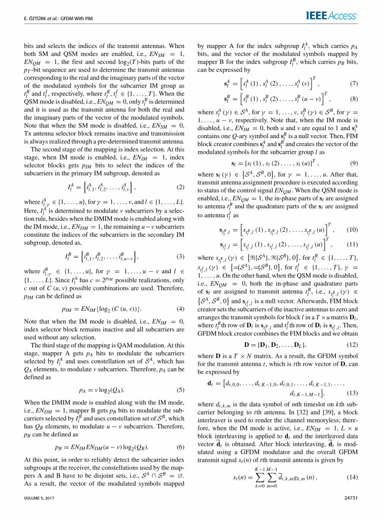
III. GFDM-FIM RECEIVERThe block diagram of the proposed GFDM-FIM receiver isgiven in Fig. 2. After the removal of CP, assuming that thewireless channel remains constant during the transmissionof a GFDM block, CP is longer than the tap length of the
channel (NCh) and perfect synchronization is ensured,the overall received signal can be expressed asy1...
yR
=H1,1 · · · H1,T
.... . .
...
HR,1 · · · HR,T
x1...
xT
+w1...
wR
, (19)
where yr = [yr (0), yr (1), . . . , yr (N − 1)]T is the vectorof received signals at the r th receive antenna, Hr,t , fort = 1, . . . ,T , r = 1, . . . ,R, is the N × N cir-cular convolution matrix constructed from the channelimpulse response coefficients between the tth transmitantenna and the r th receive antenna given by hr,t =[hr,t (0), hr,t (1), . . . , hr,t (NCh − 1)
]T, where hr,t (n) followsCN (0, 1) distribution,wr is an N ×1 vector of additive whiteGaussian noise (AWGN) samples with elements distributedas CN (0, σ 2
w). After substituting (16) in (19), we obtainy1...yR
=H1,1A · · · H1,TA
.... . .
...
HR,1A · · · HR,TA
d1...
dT
+w1...
wR
. (20)
(20) can be rewritten in a more compact form as
y = Hd+ w, (21)
where the dimensions of y, H, d and w are NR×1, NR×NT ,NT × 1 and NR × 1, respectively. The most critical part ofthe GFDM-FIM receiver is the block of MIMO detection,GFDM and SFIM demodulation. For MIMO-OFDM, MIMOdetection and SFIM demodulation can be performed at thesubcarrier level due to orthogonality in the frequency domain.
24732 VOLUME 5, 2017

E. ÖZTÜRK et al.: GFDM With FIM
FIGURE 3. Block diagram of the ZF-SDD based separate MIMO detection, GFDM and SFIM demodulation.
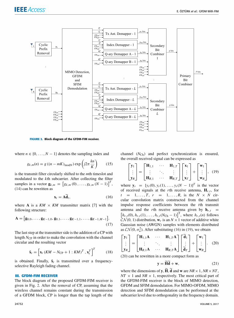
InGFDM, the inherent intercarrier interference (ICI) preventsthe frequency domain decoupling of GFDM subcarriers forboth SISO and MIMO transmission schemes. In [37], MIMOdetection, GFDM demodulation and spatial demodulationare treated independently, where a poor error performancehas been obtained. In [39], GFDM demodulation and indexdemodulation are handled as two distinct tasks. In [40],while joint MIMO detection and GFDM demodulation hasbeen proposed, SFIM demodulation has been treated in anindependent way. As will be shown later, these methods arealso applicable for the GFDM-FIM receiver. Besides, in thispaper, a new method is proposed by treating MIMO detec-tion, GFDM and SFIM demodulation jointly. These methodswill be presented as three alternatives for MIMO detection,GFDM and SFIM demodulation block of the GFDM-FIMreceiver in the subsequent subsections.
After MIMO detection, GFDM and SFIM demodulation,the information bits are recovered by applying the inversemapping process for both modulated symbols and indices ofthe active transmit antennas and subcarriers. Then, the sec-ondary bit combiner combines the outputs of the demappersand forms the p-bit sequence, which is the estimate of theinput of the secondary bit splitter. Finally, the primary bitcombiner combines all p-bit groups and forms the originalP-bit data sequence.
A. ZF-SDD BASED SEPARATE MIMO DETECTION,GFDM AND SFIM DEMODULATIONThe block diagram of the proposed ZF-SDD Based SeparateMIMO Detection, GFDM and SFIM Demodulation methodis given in Fig. 3. Based on the system model of (19), afterperforming fast Fourier transform (FFT) operations in eachantenna branch of the receiver, the input-output relation-ship of the GFDM-FIM scheme in the frequency domain isobtained as
yFr =T∑t=1
diag(xFt )hFr,t + wF
r , (22)
where yFr = [yFr (0), yFr (1), . . . , y
Fr (N − 1)]T is the vector of
received signals at the r th receive antenna, for r = 1, . . . ,R,
and hFr,t =[hFr,t (0), h
Fr,t (1), . . . , h
Fr,t (N − 1)
]T is the fre-quency response of the wireless channel between the trans-mit antenna t and receive antenna r , where hFr,t (γ ) followsCN (0, 1) distribution,wF
r is an N×1 vector of noise samplesdistributed as CN (0, σ 2
w). Since GFDM block is made upof KM subcarriers, the following signal model is obtainedfrom (22) for kth subcarrier of mth subsymbol:yF1 (k,m)
yF2 (k,m)...
yFR (k,m)
=hF1,1(k,m) · · · hF1,T (k,m)
hF2,1(k,m) · · · hF2,T (k,m)...
. . ....
hFR,1(k,m) · · · hFR,T (k,m)
xF1 (k,m)
xF2 (k,m)...
xFT (k,m)
+
wF1 (k,m)
wF2 (k,m)...
wFR (k,m)
. (23)
(23) can be rewritten in a more compact form as
yFk,m = HFk,mx
Fk,m + wF
k,m, (24)
where yFk,m is the received signal vector, HFk,m, for k =
0, . . . ,K −1,m = 0, . . . ,M −1, is the R×T correspondingchannel matrix that contains the channel coefficients betweentransmit and receive antennas and assumed to be perfectlyknown at the receiver, xFk,m is the data vector, which containsthe simultaneously transmitted symbols from all transmitantennas and wF
k,m is the noise vector. Here, an estimateof xFk,m can be obtained by using ZF detection approach asfollows:
xFk,m =(HFk,m
)−1yFk,m. (25)
Rearranging of vectors xFk,m as column vectors of a matrixgives
XF=
[(xF0,0)
T , . . . , (xFK−1,0)T , (xF0,1)
T , . . . , (xFK−1,M−1)T],
(26)
where each row contains an estimate of the frequency domainrepresentation of the transmit vector for the corresponding
VOLUME 5, 2017 24733
E. ÖZTÜRK et al.: GFDM With FIM
FIGURE 4. Block diagram of the MMSE-JDD based joint MIMO detection and GFDMdemodulation, separate SFIM demodulation.
antenna, that is:
XF=
xF1xF2...
xFT
. (27)
Then, inverse FFT (IFFT) of size N is applied to xFt and xtis obtained. Afterwards, linear GFDM demodulation of thext is obtained by using ZF approach:
dt = A−1xt (28)
After this point, if block interleaving was applied at thetransmitter, L × u block deinterleaving is applied to dt anddt is obtained. SFIM block splitter partitions dt into L groupswith length u and arranges these groups in a T × u matrixgiven by
Dl =
s1,l...
sT ,l
=d1((l − 1)u+ 1 : lu)
...
dT ((l − 1)u+ 1 : lu)
. (29)
Note that when the IM mode is disabled, i.e., ENIM = 0, u isequal to 1 and st,l , for t = 1, . . . ,T , has only one element.Then, SFIM block demodulator makes a joint decision on theindices of transmit antennas corresponding to the in-phaseand the quadrature parts of the vector of the modulatedsymbols, subcarrier index subgroups as well as constel-lation symbols considering all possible realizations of Dlby minimizing the following metric:{
tRl , tIl , I
Al , s
Al , s
Bl
}= argmin
t,IA,SA,SB‖Dl − Dl‖
2F . (30)
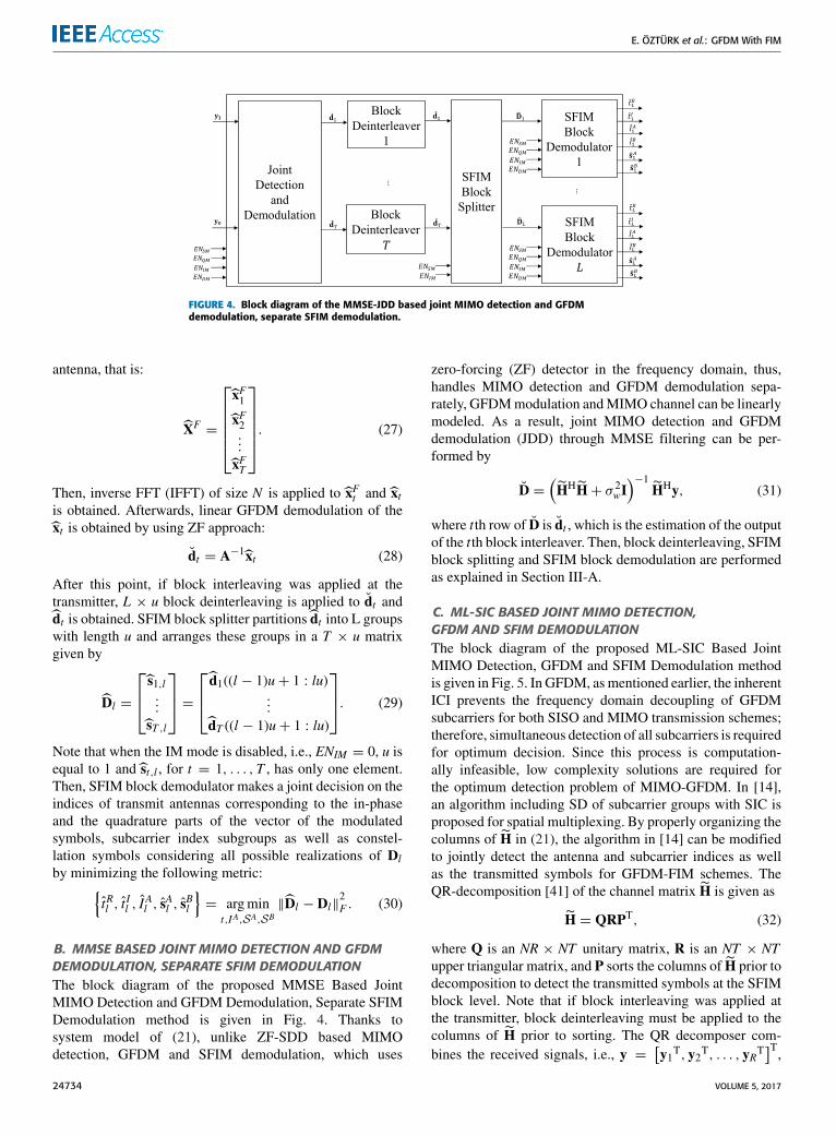
B. MMSE BASED JOINT MIMO DETECTION AND GFDMDEMODULATION, SEPARATE SFIM DEMODULATIONThe block diagram of the proposed MMSE Based JointMIMO Detection and GFDM Demodulation, Separate SFIMDemodulation method is given in Fig. 4. Thanks tosystem model of (21), unlike ZF-SDD based MIMOdetection, GFDM and SFIM demodulation, which uses
zero-forcing (ZF) detector in the frequency domain, thus,handles MIMO detection and GFDM demodulation sepa-rately, GFDMmodulation andMIMO channel can be linearlymodeled. As a result, joint MIMO detection and GFDMdemodulation (JDD) through MMSE filtering can be per-formed by
D =(HHH+ σ 2
wI)−1
HHy, (31)
where tth row of D is dt , which is the estimation of the outputof the tth block interleaver. Then, block deinterleaving, SFIMblock splitting and SFIM block demodulation are performedas explained in Section III-A.
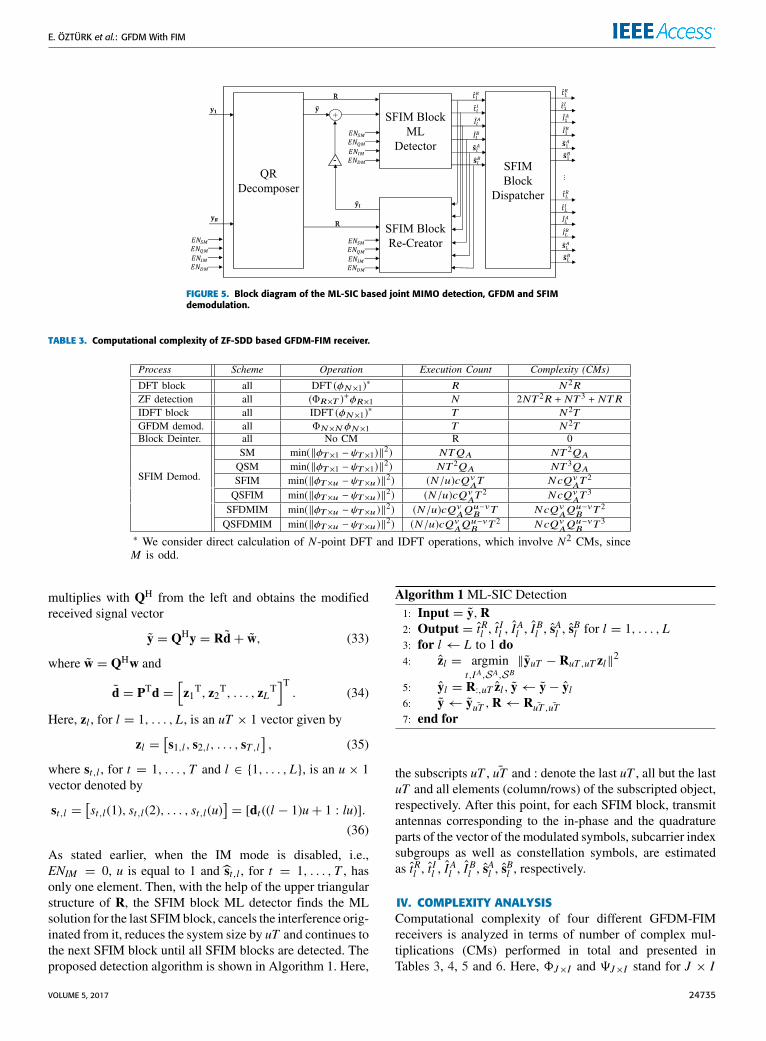
C. ML-SIC BASED JOINT MIMO DETECTION,GFDM AND SFIM DEMODULATIONThe block diagram of the proposed ML-SIC Based JointMIMO Detection, GFDM and SFIM Demodulation methodis given in Fig. 5. In GFDM, asmentioned earlier, the inherentICI prevents the frequency domain decoupling of GFDMsubcarriers for both SISO and MIMO transmission schemes;therefore, simultaneous detection of all subcarriers is requiredfor optimum decision. Since this process is computation-ally infeasible, low complexity solutions are required forthe optimum detection problem of MIMO-GFDM. In [14],an algorithm including SD of subcarrier groups with SIC isproposed for spatial multiplexing. By properly organizing thecolumns of H in (21), the algorithm in [14] can be modifiedto jointly detect the antenna and subcarrier indices as wellas the transmitted symbols for GFDM-FIM schemes. TheQR-decomposition [41] of the channel matrix H is given as
H = QRPT, (32)
where Q is an NR × NT unitary matrix, R is an NT × NTupper triangular matrix, and P sorts the columns of H prior todecomposition to detect the transmitted symbols at the SFIMblock level. Note that if block interleaving was applied atthe transmitter, block deinterleaving must be applied to thecolumns of H prior to sorting. The QR decomposer com-bines the received signals, i.e., y =
[y1T, y2T, . . . , yRT
]T,
24734 VOLUME 5, 2017
E. ÖZTÜRK et al.: GFDM With FIM
FIGURE 5. Block diagram of the ML-SIC based joint MIMO detection, GFDM and SFIMdemodulation.
TABLE 3. Computational complexity of ZF-SDD based GFDM-FIM receiver.
multiplies with QH from the left and obtains the modifiedreceived signal vector
y = QHy = Rd+ w, (33)
where w = QHw and
d = PTd =[z1T, z2T, . . . , zLT
]T. (34)
Here, zl , for l = 1, . . . ,L, is an uT × 1 vector given by
zl =[s1,l, s2,l, . . . , sT ,l
], (35)
where st,l , for t = 1, . . . ,T and l ∈ {1, . . . ,L}, is an u × 1vector denoted by
st,l =[st,l(1), st,l(2), . . . , st,l(u)
]= [dt ((l − 1)u+ 1 : lu)].
(36)
As stated earlier, when the IM mode is disabled, i.e.,ENIM = 0, u is equal to 1 and st,l , for t = 1, . . . ,T , hasonly one element. Then, with the help of the upper triangularstructure of R, the SFIM block ML detector finds the MLsolution for the last SFIMblock, cancels the interference orig-inated from it, reduces the system size by uT and continues tothe next SFIM block until all SFIM blocks are detected. Theproposed detection algorithm is shown in Algorithm 1. Here,
Algorithm 1 ML-SIC Detection1: Input = y,R2: Output = tRl , t
Il , I
Al , I
Bl , s
Al , s
Bl for l = 1, . . . ,L
3: for l ← L to 1 do4: zl = argmin
t,IA,SA,SB‖yuT − RuT ,uT zl‖2
5: yl = R:,uT zl, y← y− yl6: y← y ¯uT ,R← R ¯uT , ¯uT7: end for
the subscripts uT , ¯uT and : denote the last uT , all but the lastuT and all elements (column/rows) of the subscripted object,respectively. After this point, for each SFIM block, transmitantennas corresponding to the in-phase and the quadratureparts of the vector of the modulated symbols, subcarrier indexsubgroups as well as constellation symbols, are estimatedas tRl , t
Il , I
Al , I
Bl , s
Al , s
Bl , respectively.
IV. COMPLEXITY ANALYSISComputational complexity of four different GFDM-FIMreceivers is analyzed in terms of number of complex mul-tiplications (CMs) performed in total and presented inTables 3, 4, 5 and 6. Here, 8J×I and 9J×I stand for J × I
VOLUME 5, 2017 24735
E. ÖZTÜRK et al.: GFDM With FIM
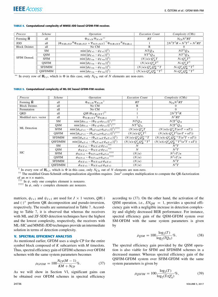
TABLE 4. Computational complexity of MMSE-JDD based GFDM-FIM receiver.
TABLE 5. Computational complexity of ML-SIC based GFDM-FIM receiver.
matrices, φJ×1 and ψJ×1 are used for J × 1 vectors, QR(·)and (·)+ perform QR decomposition and pseudo-inversion,respectively. The results are summarized in Table 7. Accord-ing to Table 7, it is observed that whereas the receiverswith ML and ZF-SDD detection techniques have the highestand the lowest complexity, respectively, the receivers withML-SIC andMMSE-JDD techniques provide an intermediatesolution in terms of detection complexity.
V. SPECTRAL EFFICIENCY ANALYSISAs mentioned earlier, GFDM uses a single CP for the entiresymbol block composed of K subcarriers with M timeslots.Thus, spectral efficiency gain of GFDM schemes over OFDMschemes with the same system parameters becomes
ρGFDM = 100NCP(M − 1)KM + NCP
%. (37)
As we will show in Section VI, significant gains canbe obtained over OFDM schemes in spectral efficiency
according to (37). On the other hand, the activation of theQSM operation, i.e., ENQM = 1, provides a spectral effi-ciency gain with a negligible increase in detection complex-ity and slightly decreased BER performance. For instance,spectral efficiency gain of the QSM-GFDM system overSM-OFDM with the same system parameters is givenby
ρQSM = 100log2(T )
log2(TQA)%. (38)
The spectral efficiency gain provided by the QSM opera-tion is also viable for SFIM and SFDMIM schemes in adecreased manner. Whereas spectral efficiency gain of theQSFIM-GFDM system over SFIM-GFDM with the samesystem parameters is given by
ρQSFIM = 100log2(T )
log2(TcQvA)%, (39)
24736 VOLUME 5, 2017
E. ÖZTÜRK et al.: GFDM With FIM
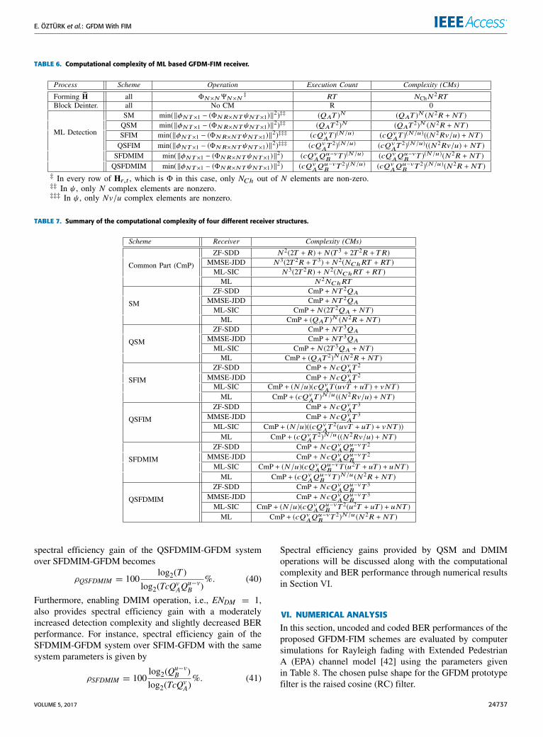
TABLE 6. Computational complexity of ML based GFDM-FIM receiver.
TABLE 7. Summary of the computational complexity of four different receiver structures.
spectral efficiency gain of the QSFDMIM-GFDM systemover SFDMIM-GFDM becomes
ρQSFDMIM = 100log2(T )
log2(TcQvAQ
u−vB )
%. (40)
Furthermore, enabling DMIM operation, i.e., ENDM = 1,also provides spectral efficiency gain with a moderatelyincreased detection complexity and slightly decreased BERperformance. For instance, spectral efficiency gain of theSFDMIM-GFDM system over SFIM-GFDM with the samesystem parameters is given by
ρSFDMIM = 100log2(Q
u−vB )
log2(TcQvA)%. (41)
Spectral efficiency gains provided by QSM and DMIMoperations will be discussed along with the computationalcomplexity and BER performance through numerical resultsin Section VI.
VI. NUMERICAL ANALYSISIn this section, uncoded and coded BER performances of theproposed GFDM-FIM schemes are evaluated by computersimulations for Rayleigh fading with Extended PedestrianA (EPA) channel model [42] using the parameters givenin Table 8. The chosen pulse shape for the GFDM prototypefilter is the raised cosine (RC) filter.
VOLUME 5, 2017 24737

E. ÖZTÜRK et al.: GFDM With FIM
FIGURE 6. Uncoded BER performance of ZF-SDD, MMSE-JDD, ML-SIC andML detection methods for (a) 2× 2 (b) 4× 4 SM schemes using 4-QAMand a roll-off factor of 0.1.
FIGURE 7. Uncoded BER performance of ZF-SDD, MMSE-JDD, ML-SIC andML detection methods for (a) 2× 2 (b) 4× 4 QSM schemes using 4-QAMand a roll-off factor of 0.1.
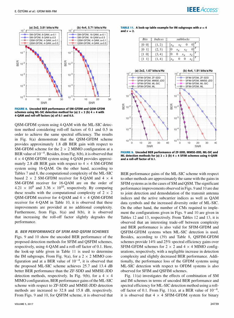
A. BER PERFORMANCE OF SM AND QSM SCHEMESFigs. 6 and 7 show the uncoded BER performance of theproposed detection methods for SM-GFDM and QSM-GFDM schemes, respectively, using 4-QAM and a roll-offfactor of 0.1. From Fig. 6(a), for a 2 × 2 MIMO config-uration and at a BER value of 10−4, it is observed thatthe proposed ML-SIC scheme achieves 18.1 and 13.7 dBbetter BER performance than the ZF-SDD and MMSE-JDDdetection methods, respectively. In Fig. 6(b), BER perfor-mance gains of the ML-SIC scheme with respect to ZF-SDDand MMSE-JDD detection methods for a 4 × 4 MIMOconfiguration are increased to 28.7 and 21 dB, respectively.Besides, from Figs. 6 and 7, for 2×2 and 4×4 QSM-GFDMsystems using 4-QAM, it is observed that BER performancegains of the ML-SIC scheme with respect to other methodsare approximately the same with SM-GFDM counterparts.This significant performance improvement of the ML-SIC
TABLE 8. Simulation parameters.
TABLE 9. The total number of CMs for SM-GFDM receivers using 4-QAM.
TABLE 10. The total number of CMs for QSM-GFDM receiversusing 4-QAM.
detection method arises from the joint detection and demod-ulation of the transmit antenna indices and the data sym-bols in a near-optimal manner. In addition, it is observedthat increasing the number of antennas enhances the BERperformance of the ML-SIC detector. The reason behind thisimprovement is the increased diversity order of the ML-SICdetector with the number of receive antennas. On the otherhand, the number of CMs required to implement the configu-rations given in Figs. 6 and 7 are given in Tables 9 and 10,respectively. From Tables 9 and 10, as mentioned earlier,it is observed that whereas the receivers with ML andZF-SDD detection techniques have the highest and the low-est complexity, respectively, the receivers with ML-SIC andMMSE-JDD techniques provide an intermediate solution interms of detection complexity. Therefore, ML-SIC detec-tion technique can provide an interesting trade-off betweencomplexity and BER performance for SM-GFDM andQSM-GFDM systems.
Figs. 6 and 7 include BER performances of OFDM appli-cations with ML detection in addition to GFDM schemes.From Figs. 6 and 7, it is observed that BER performancesof the SM-GFDM and QSM-GFDM systems with ML-SICdetection are slightly worse than their OFDM counterpartswith ML detection. The performance loss of the GFDMschemes with ML-SIC detection is due to nonorthogonalsubcarriers and the error propagation of the QR decomposi-tion used in ML-SIC detection. However, according to (37)and Table 8, the GFDM schemes provide 19% spectral effi-ciency gain over the OFDM schemes. Furthermore, from (38)and Table 8, it is observed that spectral efficiency gainsof QSM-GFDM scheme over SM-GFDM schemes using4-QAMbecome 33% and 50% for 2×2 and 4×4MIMO con-figurations, respectively, with a negligible increase in detec-tion complexity and slightly decreased BER performance.
Fig. 8(a) compares the uncoded BER performances ofthe 2 × 2 SM-GFDM system using 8-QAM and the 2 × 2
24738 VOLUME 5, 2017
E. ÖZTÜRK et al.: GFDM With FIM
FIGURE 8. Uncoded BER performance of SM-GFDM and QSM-GFDMschemes using ML-SIC detection method for (a) 2× 2 (b) 4× 4 with4-QAM and roll-off factors (a) of 0.1 and 0.5.
QSM-GFDM system using 4-QAM with the ML-SIC detec-tion method considering roll-off factors of 0.1 and 0.5 inorder to achieve the same spectral efficiency. The resultsin Fig. 8(a) demonstrate that the QSM-GFDM schemeprovides approximately 1.8 dB BER gain with respect toSM-GFDM scheme for the 2 × 2 MIMO configuration at aBER value of 10−4. Besides, fromFig. 8(b), it is observed that4 × 4 QSM-GFDM system using 4-QAM provides approxi-mately 2.8 dB BER gain with respect to 4 × 4 SM-GFDMsystem using 16-QAM. On the other hand, according toTables 7 and 8, the computational complexity of the ML-SICbased 2 × 2 SM-GFDM receiver for 8-QAM and 4 × 4SM-GFDM receiver for 16-QAM are on the order of4.21 × 109 and 3.36 × 10¹⁰, respectively. By comparingthese results with the computational complexity of 2 × 2QSM-GFDM receiver for 4-QAM and 4 × 4 QSM-GFDMreceiver for 4-QAM in Table 10, it is observed that theseimprovements are provided at no additional complexity.Furthermore, from Figs. 8(a) and 8(b), it is observedthat increasing the roll-off factor slightly degrades theperformance.
B. BER PERFORMANCE OF SFIM AND QSFIM SCHEMESFigs. 9 and 10 show the uncoded BER performance of theproposed detection methods for SFIM and QSFIM schemes,respectively, using 4-QAM and a roll-off factor of 0.1. Here,the look-up table given in Table 11 is used to determinethe IM subgroups. From Fig. 9(a), for a 2 × 2 MIMO con-figuration and at a BER value of 10−4, it is observed thatthe proposed ML-SIC scheme achieves 25.7 and 13.4 dBbetter BER performance than the ZF-SDD and MMSE-JDDdetection methods, respectively. In Fig. 9(b), for a 4 × 4MIMOconfiguration, BER performance gains of theML-SICscheme with respect to ZF-SDD and MMSE-JDD detectionmethods are increased to 32.8 and 15.8 dB, respectively.From Figs. 9 and 10, for QSFIM scheme, it is observed that
TABLE 11. A look-up table example for IM subgroups with u = 4and v = 2.
FIGURE 9. Uncoded BER performance of ZF-SDD, MMSE-JDD, ML-SIC andML detection methods for (a) 2× 2 (b) 4× 4 SFIM schemes using 4-QAMand a roll-off factor of 0.1.
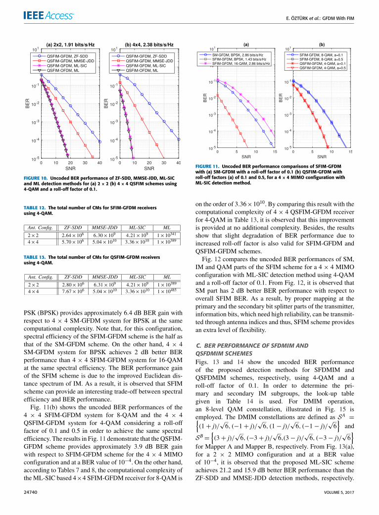
BER performance gains of the ML-SIC scheme with respectto other methods are approximately the samewith the gains inSFIM systems as in the cases of SMandQSM. The significantperformance improvements observed in Figs. 9 and 10 are dueto joint detection and demodulation of the transmit antennaindices and the active subcarrier indices as well as QAMdata symbols and the increased diversity order of ML-SIC.On the other hand, the number of CMs required to imple-ment the configurations given in Figs. 9 and 10 are given inTables 12 and 13, respectively. From Tables 12 and 13, it isobserved that an interesting trade-off between complexityand BER performance is also valid for SFIM-GFDM andQSFIM-GFDM systems when ML-SIC detection is used.Besides, according to (39) and Table 8, QSFIM-GFDMschemes provide 14% and 25% spectral efficiency gains overSFIM-GFDM schemes for 2 × 2 and 4 × 4 MIMO config-urations, respectively, with a negligible increase in detectioncomplexity and slightly decreased BER performance. Addi-tionally, the performance loss of the GFDM systems usingML-SIC detection with respect to OFDM systems is alsoobserved for SFIM and QSFIM schemes.
Fig. 11(a) investigates the effects of combination of SMand IM schemes in terms of uncoded BER performance andspectral efficiency for ML-SIC detection method using a roll-off factor of 0.1. From Fig. 11(a), at a BER value of 10−4,it is observed that 4 × 4 SFIM-GFDM system for binary
VOLUME 5, 2017 24739
E. ÖZTÜRK et al.: GFDM With FIM
FIGURE 10. Uncoded BER performance of ZF-SDD, MMSE-JDD, ML-SICand ML detection methods for (a) 2× 2 (b) 4× 4 QSFIM schemes using4-QAM and a roll-off factor of 0.1.
TABLE 12. The total number of CMs for SFIM-GFDM receiversusing 4-QAM.
TABLE 13. The total number of CMs for QSFIM-GFDM receiversusing 4-QAM.
PSK (BPSK) provides approximately 6.4 dB BER gain withrespect to 4 × 4 SM-GFDM system for BPSK at the samecomputational complexity. Note that, for this configuration,spectral efficiency of the SFIM-GFDM scheme is the half asthat of the SM-GFDM scheme. On the other hand, 4 × 4SM-GFDM system for BPSK achieves 2 dB better BERperformance than 4 × 4 SFIM-GFDM system for 16-QAMat the same spectral efficiency. The BER performance gainof the SFIM scheme is due to the improved Euclidean dis-tance spectrum of IM. As a result, it is observed that SFIMscheme can provide an interesting trade-off between spectralefficiency and BER performance.
Fig. 11(b) shows the uncoded BER performances of the4 × 4 SFIM-GFDM system for 8-QAM and the 4 × 4QSFIM-GFDM system for 4-QAM considering a roll-offfactor of 0.1 and 0.5 in order to achieve the same spectralefficiency. The results in Fig. 11 demonstrate that theQSFIM-GFDM scheme provides approximately 3.9 dB BER gainwith respect to SFIM-GFDM scheme for the 4 × 4 MIMOconfiguration and at a BER value of 10−4. On the other hand,according to Tables 7 and 8, the computational complexity ofthe ML-SIC based 4×4 SFIM-GFDM receiver for 8-QAM is
FIGURE 11. Uncoded BER performance comparisons of SFIM-GFDMwith (a) SM-GFDM with a roll-off factor of 0.1 (b) QSFIM-GFDM withroll-off factors (a) of 0.1 and 0.5, for a 4× 4 MIMO configuration withML-SIC detection method.
on the order of 3.36×10¹⁰. By comparing this result with thecomputational complexity of 4 × 4 QSFIM-GFDM receiverfor 4-QAM in Table 13, it is observed that this improvementis provided at no additional complexity. Besides, the resultsshow that slight degradation of BER performance due toincreased roll-off factor is also valid for SFIM-GFDM andQSFIM-GFDM schemes.
Fig. 12 compares the uncoded BER performances of SM,IM and QAM parts of the SFIM scheme for a 4 × 4 MIMOconfiguration with ML-SIC detection method using 4-QAMand a roll-off factor of 0.1. From Fig. 12, it is observed thatSM part has 2 dB better BER performance with respect tooverall SFIM BER. As a result, by proper mapping at theprimary and the secondary bit splitter parts of the transmitter,information bits, which need high reliability, can be transmit-ted through antenna indices and thus, SFIM scheme providesan extra level of flexibility.
C. BER PERFORMANCE OF SFDMIM ANDQSFDMIM SCHEMESFigs. 13 and 14 show the uncoded BER performanceof the proposed detection methods for SFDMIM andQSFDMIM schemes, respectively, using 4-QAM and aroll-off factor of 0.1. In order to determine the pri-mary and secondary IM subgroups, the look-up tablegiven in Table 14 is used. For DMIM operation,an 8-level QAM constellation, illustrated in Fig. 15 isemployed. The DMIM constellations are defined as SA ={(1+ j)/
√6, (−1+ j)/
√6, (1− j)/
√6, (−1− j)/
√6}
and
SB={(3+ j)/
√6, (−3+ j)/
√6,(3− j)/
√6, (−3− j)/
√6}
for Mapper A and Mapper B, respectively. From Fig. 13(a),for a 2 × 2 MIMO configuration and at a BER valueof 10−4, it is observed that the proposed ML-SIC schemeachieves 21.2 and 15.9 dB better BER performance than theZF-SDD and MMSE-JDD detection methods, respectively.
24740 VOLUME 5, 2017

E. ÖZTÜRK et al.: GFDM With FIM
FIGURE 12. Uncoded BER performance comparisons of SM, IM and QAMparts of SFIM-GFDM scheme for a 4× 4 MIMO configuration with ML-SICdetection method using 4-QAM and a roll-off factor of 0.1.
FIGURE 13. Uncoded BER performance of ZF-SDD, MMSE-JDD, ML-SICand ML detection methods for (a) 2× 2 (b) 4× 4 SFDMIM schemes using4-QAM and a roll-off factor of 0.1.
TABLE 14. A look-up table example for DMIM subgroupswith u = 4, v = 2.
In Fig. 13(b), for 4 × 4 MIMO configuration, BER per-formance gains of the ML-SIC scheme with respect toZF-SDD and MMSE-JDD detection methods were increasedto 29.2 and 20.4 dB, respectively. From Fig. 14, for QSFD-MIM scheme, it is observed that BER performance gainsof the ML-SIC scheme are approximately the same with
FIGURE 14. Uncoded BER performance of ZF-SDD, MMSE-JDD, ML-SICand ML detection methods for (a) 2× 2 (b) 4× 4 QSFDMIM schemesusing 4-QAM and a roll-off factor of 0.1.
TABLE 15. The total number of CMs for SFDMIM-GFDM receiversusing 4-QAM.
TABLE 16. The total number of CMs for QSFDMIM-GFDM receiversusing 4-QAM.
the SFDMIM system. On the other hand, the number ofCMs required to implement the configurations given inFigs. 13 and 14 are given in Tables 15 and 16, respectively.From Tables 15 and 16, it is observed that the interestingtrade-off between complexity and BER performance is alsovalid for SFDMIM-GFDM and QSFDMIM-GFDM systemswhen ML-SIC detection is used. Furthermore, from (41)and Table 8, it is observed that spectral efficiency gains ofSFDMIM-GFDM scheme over SFIM-GFDM schemes using4-QAM become 57% and 50% for 2 × 2 and 4 × 4 MIMOconfigurations, respectively. On the other hand, from (40)and Table 8, it is observed that spectral efficiency gains ofQSFDMIM-GFDM scheme over SFDMIM-GFDM schemesusing 4-QAM become 9% and 16% for 2×2 and 4×4MIMOconfigurations, respectively. For both cases, a negligibleincrease in detection complexity and a slightly decreasedBER performance are noticed. Additionally, the performanceloss of the GFDM systems using ML-SIC detection withrespect to OFDM systems is also observed for SFDMIM andQSFDMIM schemes.
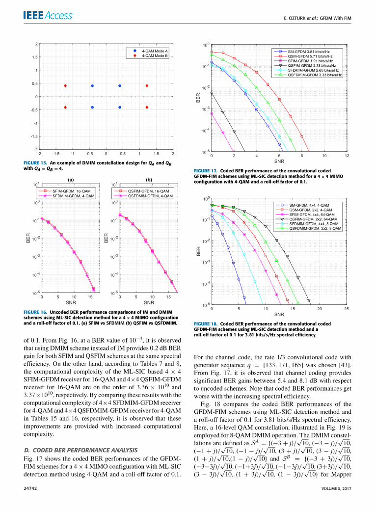
Fig. 16 investigates the effect of DMIM operation in termsof uncoded BER performances for a 4 × 4 MIMO config-uration with ML-SIC detection method and a roll-off factor
VOLUME 5, 2017 24741
E. ÖZTÜRK et al.: GFDM With FIM
FIGURE 15. An example of DMIM constellation design for QA and QBwith QA = QB = 4.
FIGURE 16. Uncoded BER performance comparisons of IM and DMIMschemes using ML-SIC detection method for a 4× 4 MIMO configurationand a roll-off factor of 0.1. (a) SFIM vs SFDMIM (b) QSFIM vs QSFDMIM.
of 0.1. From Fig. 16, at a BER value of 10−4, it is observedthat using DMIM scheme instead of IM provides 0.2 dB BERgain for both SFIM and QSFIM schemes at the same spectralefficiency. On the other hand, according to Tables 7 and 8,the computational complexity of the ML-SIC based 4 × 4SFIM-GFDM receiver for 16-QAMand 4×4QSFIM-GFDMreceiver for 16-QAM are on the order of 3.36 × 10¹⁰ and3.37×1010, respectively. By comparing these results with thecomputational complexity of 4×4 SFDMIM-GFDM receiverfor 4-QAMand 4×4QSFDMIM-GFDM receiver for 4-QAMin Tables 15 and 16, respectively, it is observed that theseimprovements are provided with increased computationalcomplexity.
D. CODED BER PERFORMANCE ANALYSISFig. 17 shows the coded BER performances of the GFDM-FIM schemes for a 4× 4 MIMO configuration with ML-SICdetection method using 4-QAM and a roll-off factor of 0.1.
FIGURE 17. Coded BER performance of the convolutional codedGFDM-FIM schemes using ML-SIC detection method for a 4× 4 MIMOconfiguration with 4-QAM and a roll-off factor of 0.1.
FIGURE 18. Coded BER performance of the convolutional codedGFDM-FIM schemes using ML-SIC detection method and aroll-off factor of 0.1 for 3.81 bits/s/Hz spectral efficiency.
For the channel code, the rate 1/3 convolutional code withgenerator sequence q = [133, 171, 165] was chosen [43].From Fig. 17, it is observed that channel coding providessignificant BER gains between 5.4 and 8.1 dB with respectto uncoded schemes. Note that coded BER performances getworse with the increasing spectral efficiency.
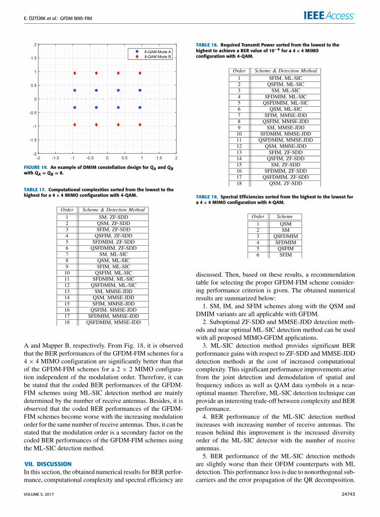
Fig. 18 compares the coded BER performances of theGFDM-FIM schemes using ML-SIC detection method anda roll-off factor of 0.1 for 3.81 bits/s/Hz spectral efficiency.Here, a 16-level QAM constellation, illustrated in Fig. 19 isemployed for 8-QAMDMIM operation. The DMIM constel-lations are defined as SA = {(−3 + j)/
√10, (−3 − j)/
√10,
(−1 + j)/√10, (−1 − j)/
√10, (3 + j)/
√10, (3 − j)/
√10,
(1 + j)/√10,(1 − j)/
√10} and SB = {(−3 + 3j)/
√10,
(−3−3j)/√10, (−1+3j)/
√10, (−1−3j)/
√10, (3+3j)/
√10,
(3 − 3j)/√10, (1 + 3j)/
√10, (1 − 3j)/
√10} for Mapper
24742 VOLUME 5, 2017
E. ÖZTÜRK et al.: GFDM With FIM
FIGURE 19. An example of DMIM constellation design for QA and QBwith QA = QB = 8.
TABLE 17. Computational complexities sorted from the lowest to thehighest for a 4× 4 MIMO configuration with 4-QAM.
A and Mapper B, respectively. From Fig. 18, it is observedthat the BER performances of the GFDM-FIM schemes for a4 × 4 MIMO configuration are significantly better than thatof the GFDM-FIM schemes for a 2 × 2 MIMO configura-tion independent of the modulation order. Therefore, it canbe stated that the coded BER performances of the GFDM-FIM schemes using ML-SIC detection method are mainlydetermined by the number of receive antennas. Besides, it isobserved that the coded BER performances of the GFDM-FIM schemes become worse with the increasing modulationorder for the same number of receive antennas. Thus, it can bestated that the modulation order is a secondary factor on thecoded BER performances of the GFDM-FIM schemes usingthe ML-SIC detection method.
VII. DISCUSSIONIn this section, the obtained numerical results for BER perfor-mance, computational complexity and spectral efficiency are
TABLE 18. Required Transmit Power sorted from the lowest to thehighest to achieve a BER value of 10−4 for a 4× 4 MIMOconfiguration with 4-QAM.
TABLE 19. Spectral Efficiencies sorted from the highest to the lowest fora 4× 4 MIMO configuration with 4-QAM.
discussed. Then, based on these results, a recommendationtable for selecting the proper GFDM-FIM scheme consider-ing performance criterion is given. The obtained numericalresults are summarized below:
1. SM, IM, and SFIM schemes along with the QSM andDMIM variants are all applicable with GFDM.
2. Suboptimal ZF-SDD and MMSE-JDD detection meth-ods and near optimal ML-SIC detection method can be usedwith all proposed MIMO-GFDM applications.
3. ML-SIC detection method provides significant BERperformance gains with respect to ZF-SDD and MMSE-JDDdetection methods at the cost of increased computationalcomplexity. This significant performance improvements arisefrom the joint detection and demodulation of spatial andfrequency indices as well as QAM data symbols in a near-optimal manner. Therefore, ML-SIC detection technique canprovide an interesting trade-off between complexity and BERperformance.
4. BER performance of the ML-SIC detection methodincreases with increasing number of receive antennas. Thereason behind this improvement is the increased diversityorder of the ML-SIC detector with the number of receiveantennas.
5. BER performance of the ML-SIC detection methodsare slightly worse than their OFDM counterparts with MLdetection. This performance loss is due to nonorthogonal sub-carriers and the error propagation of the QR decomposition.
VOLUME 5, 2017 24743
E. ÖZTÜRK et al.: GFDM With FIM
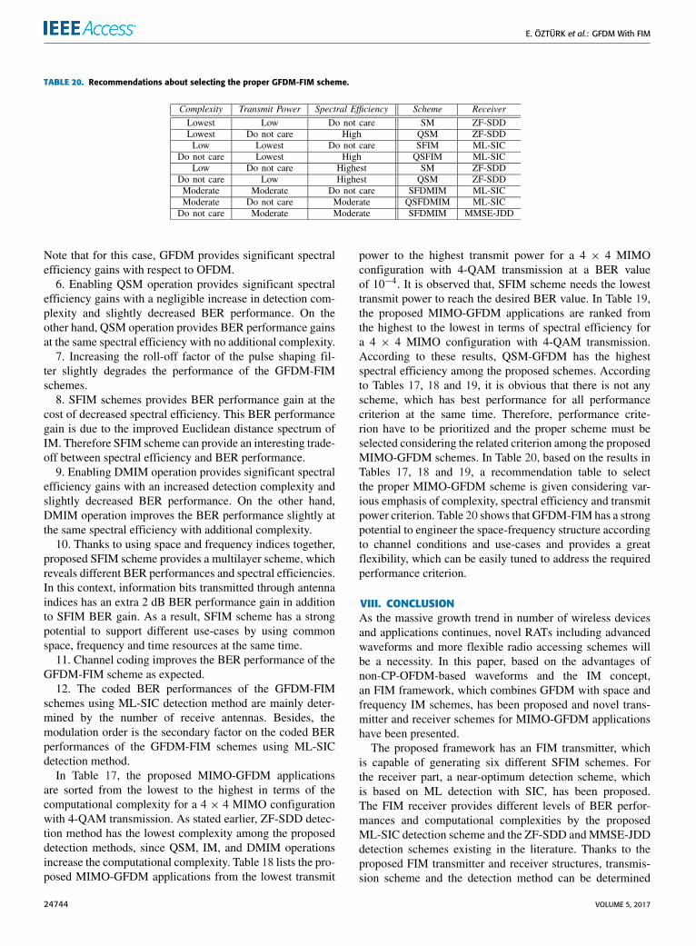
TABLE 20. Recommendations about selecting the proper GFDM-FIM scheme.
Note that for this case, GFDM provides significant spectralefficiency gains with respect to OFDM.
6. Enabling QSM operation provides significant spectralefficiency gains with a negligible increase in detection com-plexity and slightly decreased BER performance. On theother hand, QSM operation provides BER performance gainsat the same spectral efficiency with no additional complexity.
7. Increasing the roll-off factor of the pulse shaping fil-ter slightly degrades the performance of the GFDM-FIMschemes.
8. SFIM schemes provides BER performance gain at thecost of decreased spectral efficiency. This BER performancegain is due to the improved Euclidean distance spectrum ofIM. Therefore SFIM scheme can provide an interesting trade-off between spectral efficiency and BER performance.
9. Enabling DMIM operation provides significant spectralefficiency gains with an increased detection complexity andslightly decreased BER performance. On the other hand,DMIM operation improves the BER performance slightly atthe same spectral efficiency with additional complexity.
10. Thanks to using space and frequency indices together,proposed SFIM scheme provides a multilayer scheme, whichreveals different BER performances and spectral efficiencies.In this context, information bits transmitted through antennaindices has an extra 2 dB BER performance gain in additionto SFIM BER gain. As a result, SFIM scheme has a strongpotential to support different use-cases by using commonspace, frequency and time resources at the same time.
11. Channel coding improves the BER performance of theGFDM-FIM scheme as expected.
12. The coded BER performances of the GFDM-FIMschemes using ML-SIC detection method are mainly deter-mined by the number of receive antennas. Besides, themodulation order is the secondary factor on the coded BERperformances of the GFDM-FIM schemes using ML-SICdetection method.
In Table 17, the proposed MIMO-GFDM applicationsare sorted from the lowest to the highest in terms of thecomputational complexity for a 4 × 4 MIMO configurationwith 4-QAM transmission. As stated earlier, ZF-SDD detec-tion method has the lowest complexity among the proposeddetection methods, since QSM, IM, and DMIM operationsincrease the computational complexity. Table 18 lists the pro-posed MIMO-GFDM applications from the lowest transmit
power to the highest transmit power for a 4 × 4 MIMOconfiguration with 4-QAM transmission at a BER valueof 10−4. It is observed that, SFIM scheme needs the lowesttransmit power to reach the desired BER value. In Table 19,the proposed MIMO-GFDM applications are ranked fromthe highest to the lowest in terms of spectral efficiency fora 4 × 4 MIMO configuration with 4-QAM transmission.According to these results, QSM-GFDM has the highestspectral efficiency among the proposed schemes. Accordingto Tables 17, 18 and 19, it is obvious that there is not anyscheme, which has best performance for all performancecriterion at the same time. Therefore, performance crite-rion have to be prioritized and the proper scheme must beselected considering the related criterion among the proposedMIMO-GFDM schemes. In Table 20, based on the results inTables 17, 18 and 19, a recommendation table to selectthe proper MIMO-GFDM scheme is given considering var-ious emphasis of complexity, spectral efficiency and transmitpower criterion. Table 20 shows that GFDM-FIM has a strongpotential to engineer the space-frequency structure accordingto channel conditions and use-cases and provides a greatflexibility, which can be easily tuned to address the requiredperformance criterion.
VIII. CONCLUSIONAs the massive growth trend in number of wireless devicesand applications continues, novel RATs including advancedwaveforms and more flexible radio accessing schemes willbe a necessity. In this paper, based on the advantages ofnon-CP-OFDM-based waveforms and the IM concept,an FIM framework, which combines GFDM with space andfrequency IM schemes, has been proposed and novel trans-mitter and receiver schemes for MIMO-GFDM applicationshave been presented.
The proposed framework has an FIM transmitter, whichis capable of generating six different SFIM schemes. Forthe receiver part, a near-optimum detection scheme, whichis based on ML detection with SIC, has been proposed.The FIM receiver provides different levels of BER perfor-mances and computational complexities by the proposedML-SIC detection scheme and the ZF-SDD andMMSE-JDDdetection schemes existing in the literature. Thanks to theproposed FIM transmitter and receiver structures, transmis-sion scheme and the detection method can be determined
24744 VOLUME 5, 2017

E. ÖZTÜRK et al.: GFDM With FIM
according to desired level of complexity, transmit powerand spectral efficiency of the use-cases. Besides, switchingbetween different IM schemes according to channel condi-tions can be possible using a single transceiver structure.Furthermore, FIM framework provides a multilayer schemeby means of different levels of BER performances and spec-tral efficiencies and enables to support different use-cases byusing common space, frequency, and time resources at thesame time. It has been shown that GFDM-FIM has a strongpotential to engineer the space-frequency structure accordingto channel conditions and use-cases as well as it providesa great flexibility, which can be easily tuned to address therequired performance criterion.
As mentioned earlier, GFDM has a flexibility to engi-neer the time-frequency structure and beneficial properties tofulfill the requirements of future wireless networks. By inte-grating GFDMwith promising space and frequency indexingschemes in a skilled framework, GFDM-FIM can be con-sidered a promising PHY layer technique for future wire-less networks. Our future work will focus on theoreticalanalysis which can provide more insights on the impact ofsome parameters on the system performance for systematicoptimization.
REFERENCES[1] G. Wunder et al., ‘‘5GNOW: Non-orthogonal, asynchronous waveforms
for future mobile applications,’’ IEEE Commun. Mag., vol. 52, no. 2,pp. 97–105, Feb. 2014.
[2] IMT Vision Framework and Overall Objectives of the Future Devel-opment of IMT for 2020 and Beyond, document M.2083-0, ITU-R,Sep. 2015.
[3] Study on Scenarios and Requirements for Next Generation Access Tech-nologies, document 38.913, 3GPP, Feb. 2016.
[4] J. Abdoli et al., ‘‘Filtered OFDM: A new waveform for future wirelesssystems,’’ in Proc. IEEE Int. Workshop Signal Process. Adv. WirelessCommun., Stockholm, Sweden, Jun. 2015, pp. 66–70.
[5] X. Zhang, M. Jia, L. Chen, J. Ma, and J. Qiu, ‘‘Filtered-OFDM—Enabler for flexible waveform in the 5th generation cellular networks,’’in Proc. IEEE GLOBECOM Workshops, San Diego CA, USA, Dec. 2015,pp. 1–6.
[6] E. Bala, J. Li, and R. Yang, ‘‘Shaping spectral leakage: A novellow-complexity transceiver architecture for cognitive radio,’’ IEEE Veh.Technol. Mag., vol. 8, no. 3, pp. 38–46, Sep. 2013.
[7] N. Michailow et al., ‘‘Generalized frequency division multiplexing for5th generation cellular networks,’’ IEEE Trans. Commun., vol. 62, no. 9,pp. 3045–3061, Sep. 2014.
[8] M. Matthe, L. L. Mendes, and G. Fettweis, ‘‘Space-time coding for gener-alized frequency division multiplexing,’’ in Proc. 20th Eur. Wireless Conf.,Barcelona, Spain, May 2014, pp. 1–5.
[9] M. Matthe, L. L. Mendes, I. Gaspar, N. Michailov, D. Zhang, andG. Fettweis, ‘‘Widely linear estimation for space-time-coded GFDMin low latency applications,’’ IEEE Trans. Commun., vol. 63, no. 11,pp. 4501–4509, Nov. 2015.
[10] M. Matthe, L. L. Mendes, I. Gaspar, N. Michailov, D. Zhang, andG. Fettweis, ‘‘Multi-user time-reversal STC-GFDMA for future wire-less networks,’’ EURASIP J. Wireless Commun. Netw., vol. 2015, no. 1,pp. 1–8, May 2015.
[11] D. Zhang, L. L. Mendes, M. Matthe, N. Michailov, and G. Fettweis,‘‘Expectation propagation for near-optimum detection of MIMO-GFDMsignals,’’ IEEE Trans. Wireless Commun., vol. 15, no. 2, pp. 1045–1062,Feb. 2016.
[12] D. Zhang, L. L. Mendes, M. Matthe, and G. Fettweis, ‘‘A Markov chainMonte Carlo algorithm for near-optimum detection of MIMO-GFDMsignals,’’ in Proc. IEEE Pers., Indoor Mobile Radio Commun. (PIMRC),Aug. 2015, pp. 1–5.
[13] N. Tunali, M. Wu, C. Dick, C. Studer, and S. Jose, ‘‘Linear large-scaleMIMO data detection for 5G multi-carrier waveform candidates,’’ in Proc.Asilomar Conf. Signals, Syst., Comput., Nov. 2015, pp. 1–5.
[14] M. Matthe, I. Gaspar, D. Zhang, and G. Fettweis, ‘‘Near-ML detection forMIMO-GFDM,’’ in Proc. 82nd IEEE Veh. Technol. Conf. Fall, Boston,MA, USA, Sep. 2015, pp. 1–2.
[15] M. Matthe, D. Zhang, and G. Fettweis, ‘‘Iterative detection usingMMSE-PIC demapping for MIMO-GFDM systems,’’ in Proc. IEEE Eur.Wireless (EW), May 2016, pp. 1–7.
[16] M. Matthe, D. Zhang, and G. Fettweis, ‘‘Sphere-decoding aided SIC forMIMO-GFDM: Coded performance analysis,’’ inProc. Int. Symp.WirelessCommun. Syst. (ISWCS), Poznan, Poland, Sep. 2016, pp. 165–169.
[17] D. Zhang, M. Matthe, L. L. Mendes, and G. Fettweis, ‘‘A study on the linklevel performance of advanced multicarrier waveforms under MIMOwire-less communication channels,’’ IEEE Trans. Wireless Commun., vol. 16,no. 4, pp. 2350–2365, Apr. 2017.
[18] R. Y. Mesleh, H. Haas, S. Sinanovic, C. W. Ahn, and S. Yun, ‘‘Spatialmodulation,’’ IEEE Trans. Veh. Technol., vol. 57, no. 4, pp. 2228–2241,Jul. 2008.
[19] R. Mesleh, S. Ikki, and H. Aggoune, ‘‘Quadrature spatial modulation,’’IEEE Trans. Veh. Technol., vol. 64, no. 6, pp. 2738–2742, Jun. 2015.
[20] E. Basar, Ü. Aygölü, E. Panayırcı, and H. V. Poor, ‘‘Orthogonal fre-quency division multiplexing with index modulation,’’ IEEE Trans. SignalProcess., vol. 61, no. 22, pp. 5536–5549, Nov. 2013.
[21] R. Abu-alhiga and H. Haas, ‘‘Subcarrier-index modulation OFDM,’’ inProc. IEEE Int. Symp. Pers., IndoorMobile Radio Commun., Tokyo, Japan,Sep. 2009, pp. 177–181.
[22] D. Tsonev, S. Sinanovic, and H. Haas, ‘‘Enhanced subcarrier index modu-lation (SIM) OFDM,’’ in Proc. IEEE GLOBECOMWorkshops, Dec. 2011,pp. 728–732.
[23] T. Mao, Z. Wang, Q. Wang, S. Chen, and L. Hanzo, ‘‘Dual-mode indexmodulation aided OFDM,’’ IEEE Access, vol. 5, pp. 50–60, 2016.
[24] M. Wen, E. Basar, Q. Li, B. Zheng, and M. Zhang, ‘‘Multiple-modeorthogonal frequency division multiplexing with index modulation,’’ IEEETrans. Commun., vol. 65, no. 9, pp. 3892–3906, Sep. 2017.
[25] E. Basar, ‘‘OFDM with index modulation using coordinate interleaving,’’IEEE Wireless Commun. Lett., vol. 4, no. 4, pp. 381–384, Aug. 2015.
[26] R. Fan, Y. J. Yu, and Y. L. Guan, ‘‘Generalization of orthogonal frequencydivision multiplexing with index modulation,’’ IEEE Trans. WirelessCommun., vol. 14, no. 10, pp. 5350–5359, Oct. 2015.
[27] M. Wen, Y. Zhang, J. Li, E. Basar, and F. Chen, ‘‘Equiprobable subcarrieractivation method for OFDM with index modulation,’’ IEEE Commun.Lett., vol. 20, no. 12, pp. 2386–2389, Dec. 2016.
[28] M.Wen, B. Ye, E. Basar, Q. Li, and F. Ji, ‘‘Enhanced orthogonal frequencydivision multiplexing with index modulation,’’ IEEE Trans. WirelessCommun., vol. 16, no. 7, pp. 4786–4801, Jul. 2017.
[29] H. Zhang, L. L. Yang, and L. Hanzo, ‘‘Compressed sensing improvesthe performance of subcarrier index-modulation-assisted OFDM,’’ IEEEAccess, vol. 4, pp. 7859–7873, Oct. 2016.
[30] E. Başar, ‘‘Multiple-input multiple-output OFDMwith indexmodulation,’’IEEE Signal Process. Lett., vol. 22, no. 12, pp. 2259–2263, Sep. 2015.
[31] T. Datta, H. S. Eshwaraiah, and A. Chockalingam, ‘‘Generalized space-and-frequency index modulation,’’ IEEE Trans. Veh. Technol., vol. 65,no. 7, pp. 4911–4924, Jul. 2016.
[32] E. Basar, ‘‘On multiple-input multiple-output OFDM with index modula-tion for next generation wireless networks,’’ IEEE Trans. Signal Process.,vol. 64, no. 15, pp. 3868–3878, Aug. 2016.
[33] B. Zheng, M.Wen, E. Basar, and F. Chen, ‘‘Multiple-input multiple-outputOFDM with index modulation: Low-complexity detector design,’’ IEEETrans. Signal Process., vol. 65, no. 11, pp. 2758–2772, Jun. 2017.
[34] E. Basar et al., ‘‘Index modulation techniques for next-generation wirelessnetworks,’’ IEEE Access, vol. 5, no. 1, pp. 16693–16746, Sep. 2017.
[35] Study on New Radio (NR) Access Technology, document 38.912 V14.1.0,3GPP, Jun. 2017.
[36] Z. E. Ankarali, B. Peköz, and H. Arslan, ‘‘Flexible radio access beyond5G: A future projection on waveform, numerology, and frame designprinciples,’’ IEEE Access, vol. 5, pp. 18295–18309, Mar. 2017.
[37] E. Özturk, E. Basar, and H. A. Çirpan, ‘‘Spatial modulation GFDM: A lowcomplexity MIMO-GFDM system for 5G wireless networks,’’ in Proc. 4thIEEE Int. Black Sea Conf. Commun. Netw., Varna, Bulgaria, Jun. 2016,pp. 1–5.
[38] E. Basar, ‘‘Index modulation techniques for 5G wireless networks,’’ IEEECommun. Mag., vol. 54, no. 7, pp. 168–175, Jul. 2016.
VOLUME 5, 2017 24745

E. ÖZTÜRK et al.: GFDM With FIM
[39] E. Ozturk, E. Basar, and H. A. Cirpan, ‘‘Generalized frequency divisionmultiplexing with index modulation,’’ in Proc. IEEE GLOBECOM Work-shops, Washington, DC, USA, Dec. 2016, pp. 1–6.
[40] E. Ozturk, E. Basar, and H. A. Cirpan, ‘‘Generalized frequency divisionmultiplexing with space and frequency index modulations,’’ in Proc. 5thIEEE Int. Black Sea Conf. Commun. Netw., Istanbul, Turkey, Jun. 2017,pp. 1–6.
[41] D.Wübben, R. Böhnke, J. Rinas, V. Kühn, andK. D. Kammeyer, ‘‘Efficientalgorithm for decoding layered space-time codes,’’ Electron. Lett., vol. 37,no. 22, pp. 1348–1350, Oct. 2001.
[42] Base Station (BS) Radio Transmission and Reception, docu-ment 36.104 V14.4.0, 3GPP, Jun. 2017.
[43] Multiplexing and Channel Coding, document 36.212 V14.3.0, Jun. 2017.
ERSİN ÖZTÜRK received the B.S. degree inelectronics and communication engineering fromYildiz Technical University, Istanbul, Turkey,in 1995, and the M.S. degree in electronics andcommunication engineering from Istanbul Techni-cal University, Istanbul, Turkey, in 1998, where heis currently pursuing the Ph.D. degree in telecom-munication engineering. His current research areasinclude waveform design, multicarrier systems,indexmodulation, and digital signal processing forwireless communications.
ERTUGRUL BASAR (S’09–M’13–SM’16) rece-ived the B.S. degree (Hons.) from Istanbul Uni-versity, Turkey, in 2007, and the M.S. andPh.D. degrees from Istanbul Technical Universityin 2009 and 2013, respectively. He was with theDepartment of Electrical Engineering, PrincetonUniversity, NJ, USA, from 2011 to 2012. He wasan Assistant Professor with Istanbul TechnicalUniversity from 2014 to 2017, where he is cur-rently an Associate Professor of electronics and
communication engineering. He is an inventor of two pending patents onindex modulation schemes. His primary research interests include MIMOsystems, index modulation, cooperative communications, OFDM, and visi-ble light communications.
He was a recipient of the Istanbul Technical University Best Ph.D. ThesisAward in 2014. He has received three best paper awards, including one fromthe IEEE International Conference on Communications 2016. He currentlyserves as an Associate Editor for the IEEE COMMUNICATIONS LETTERS and theIEEE ACCESS, and an Editor for Physical Communication (Elsevier). He isalso a regular reviewer for various IEEE journals and has served as a TPCmember for several conferences.
HAKAN ALİ ÇIRPAN (S’95–M’00) receivedthe B.S. degree from Uludag University, Bursa,Turkey, in 1989, the M.S. degree from the IstanbulUniversity, Istanbul, Turkey, in 1992, and the Ph.D.degree from the Stevens Institute of Technology,Hoboken, NJ, USA, in 1997, all in electrical engi-neering. From 1995 to 1997, he was a ResearchAssistant with the Stevens Institute of Technol-ogy, where he was involved in signal processingalgorithms for wireless communication systems.
In 1997, he joined the Department of Electrical-Electronics Engineering,Istanbul University, as a Faculty Member. In 2010, he joined the Departmentof Electronics and Communication Engineering, Istanbul Technical Univer-sity, as a Faculty Member. His general research interests cover wireless com-munications, statistical signal and array processing, system identification,and estimation theory. His current research activities are focused on machinelearning, signal processing, and communication concepts with specific atten-tion to next generation mobile wireless communication systems. He receivedthe Peskin Award from the Stevens Institute of Technology and theProf. Nazim Terzioglu Award from the Research Fund of Istanbul University.He is a member of Sigma Xi.
24746 VOLUME 5, 2017