General Technical Report 05
173
GENERAL TECHNICAL REPORT Equipment: DETAILED ENGINEERING Order: VEC001101 Customer:ROYAL GK PTE LTD
-
Upload
htet-mrak-aung -
Category
Documents
-
view
44 -
download
15
description
Technical Re
Transcript of General Technical Report 05

GENERAL TECHNICAL
REPORT
Equipment: DETAILED ENGINEERING
Order: VEC001101
Customer:ROYAL GK PTE LTD
DOCUMENT ORDER DATE
Nov-2012
General technical report VEC001101 INDEX
CUSTOMER
ROYAL GK PTE LTD
CONSISTENTS WITH OUR CONTINUAL PRODUCT IMPROVEMENT POLICY, GUASCOR POWER RESERVES THE RIGHT TO CHANGE ANY SPECIFICATION WITHOUT PRIOR NOTICE. i
- CONTENTS -
1 PURPOSE ............................................................................................................ 1
2 GENERAL DESCRIPTION ................................................................................ 3
3 CIVIL ENGINEERING ........................................................................................ 4
3.1 Prior Data ................................................................................................... 4
3.2 Foundations ................................................................................................ 5
3.3 Electrical Installations and Pits ................................................................. 7
3.4 Drainage System ...................................................................................... 10
3.5 Exterior Flooring ...................................................................................... 12
3.6 Interior Flooring ....................................................................................... 14
3.7 Fencing ...................................................................................................... 15
3.8 Metallic Structure .................................................................................... 15
3.9 Façades ...................................................................................................... 20
3.10 Roofs .......................................................................................................... 20
4 OPERATIONAL CONDITION AND TERMS ............................................... 22
4.1 Electrical power generation .................................................................... 22
4.2 Fire& gas leak detection .......................................................................... 25
5 ENGINE AND GENERATOR ASSEMBLY .................................................... 36
5.1 Engine features ......................................................................................... 38
5.2 Alternator features .................................................................................. 40
6 ENGINE FLUE SYSTEM .................................................................................. 43
6.1 Exhaust silencer ....................................................................................... 44

DOCUMENT ORDER DATE
Nov-2012
General technical report VEC001101 INDEX
CUSTOMER
ROYAL GK PTE LTD
CONSISTENTS WITH OUR CONTINUAL PRODUCT IMPROVEMENT POLICY, GUASCOR POWER RESERVES THE RIGHT TO CHANGE ANY SPECIFICATION WITHOUT PRIOR NOTICE. ii
6.2 Exhaust chimney ...................................................................................... 44
6.3 Piping and fittings ..................................................................................... 44
6.4 Design and definition chart ..................................................................... 46
7 ENGINE COOLING SYSTEM ......................................................................... 52
7.1 Engineering basis of design ..................................................................... 53
7.2 Electrical water pumps ............................................................................ 54
7.3 Expansion vessels ..................................................................................... 54
7.4 Double core air cooler ............................................................................. 55
7.5 Piping& fittings ......................................................................................... 56
7.6 Testing & inspection ................................................................................ 59
7.7 Design & definition chart ........................................................................ 60
8 ENGINE LUBE OIL SYSTEM .......................................................................... 73
8.1 Blowby gases exhausting system ............................................................ 74
9 ENGINE VENTILATION SYSTEM ................................................................ 77
9.1 Description of the engine room ventilation .......................................... 77
9.2 Ventilation system ................................................................................... 78
10 NATURAL GAS FUEL SUPPLY ..................................................................... 80
10.1 General description ................................................................................. 80
10.2 Engineering basis of design ..................................................................... 90
10.3 Testing & inspections ............................................................................... 91
11 FIRE & GAS LEAK DETECTION SYSTEM ................................................... 93
11.1 Basis of design ........................................................................................... 95
11.2 Design & definition ................................................................................... 97
11.3 Technical specifications ......................................................................... 105

DOCUMENT ORDER DATE
Nov-2012
General technical report VEC001101 INDEX
CUSTOMER
ROYAL GK PTE LTD
CONSISTENTS WITH OUR CONTINUAL PRODUCT IMPROVEMENT POLICY, GUASCOR POWER RESERVES THE RIGHT TO CHANGE ANY SPECIFICATION WITHOUT PRIOR NOTICE. iii
12 ELECTRICAL GENERATING SYSTEM ...................................................... 117
12.1 General description ............................................................................... 117
12.2 Grounding grid ....................................................................................... 129
12.3 Engineering basis of design ................................................................... 130
12.4 Supporting calculations ......................................................................... 131
12.5 Testing & inspection .............................................................................. 138
13 ANCILLARY SERVICES.LOW VOLTAGE SYSTEM. ................................ 139
13.1 General description ............................................................................... 139
13.2 Engineering basis of design ................................................................... 145
13.3 Electrical design & definition ................................................................ 145
13.4 Testing & inspection .............................................................................. 161
14 ENVIRONMENTAL POLLUTION SOURCES AND
MEASURES ..................................................................................................... 162
14.1 Standards basis of design....................................................................... 162
14.2 Location .................................................................................................. 163
14.3 Raw and auxiliary materials .................................................................. 163
14.4 Air Pollution-Emission sources ............................................................. 165
14.5 Noise Sources ......................................................................................... 166
14.6 industrial sewage water ......................................................................... 167
14.7 Industrial residues .................................................................................. 168
14.8 Environmental measures for the site soil ............................................ 169

DOCUMENT ORDER DATE
Nov-2012
General technical report VEC001101 INDEX
CUSTOMER
ROYAL GK PTE LTD
CONSISTENTS WITH OUR CONTINUAL PRODUCT IMPROVEMENT POLICY, GUASCOR POWER RESERVES THE RIGHT TO CHANGE ANY SPECIFICATION WITHOUT PRIOR NOTICE. 1
1 PURPOSE
This project envisages the construction of a 26MW natural gas generation power plant in
the Republic of the Union of Myanmar. This power plant is conceived as a back-up to
increase the already existing power generation capacity that supplies the national grid in
the Yangon Region.
The power plant will be based on internal combustion engines technology. Although the
power plant will be managed as a single unit from a central control station, the design is
based on 26 gas gensets of 1MW, which can be also managed as independent generation
units.
The main advantage of this design is that using 1MW gensets the plant will have higher
degree of power availability in case of maintenance or reparations of the units than using
bigger sized gensets.
The plant has been designed foreseeing a future expansion with a second phase of
another 26 gensets. If this second phase is implemented the final capacity of the plant will
be of 52MW.
This new plant will be built adjacent to the existing Hlawga Gas Power Plant, which at
present day is composed by 3 gas turbines and a steam turbine, which have a total
available power capacity of 154,2MW. The gas supply for the new power plant will be
diverted from the MOGE gas regulation station that serves to the turbines.
The power plant is also adjacent to a power substation of YESB, where the turbines are
connected to Myanmar’s National Grid. The interconnection of the new power plant will
be made at the same busbar of 33kV as the turbines, using an available spare feeder.
Future expansion would require a second feeder in the same busbar.

DOCUMENT ORDER DATE
Nov-2012
General technical report VEC001101 INDEX
CUSTOMER
ROYAL GK PTE LTD
CONSISTENTS WITH OUR CONTINUAL PRODUCT IMPROVEMENT POLICY, GUASCOR POWER RESERVES THE RIGHT TO CHANGE ANY SPECIFICATION WITHOUT PRIOR NOTICE. 2
HlawgaPowerPlant
(Turbines)
YESB Substation (33kV)
Interconnectionfeeder
DOCUMENT ORDER DATE
Nov-2012
General technical report VEC001101 INDEX
CUSTOMER
ROYAL GK PTE LTD
CONSISTENTS WITH OUR CONTINUAL PRODUCT IMPROVEMENT POLICY, GUASCOR POWER RESERVES THE RIGHT TO CHANGE ANY SPECIFICATION WITHOUT PRIOR NOTICE. 3
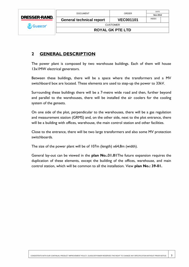
2 GENERAL DESCRIPTION
The power plant is composed by two warehouse buildings. Each of them will house
13x1MW electrical generators.
Between these buildings, there will be a space where the transformers and a MV
switchboard box are located. These elements are used to step-up the power to 33kV.
Surrounding these buildings there will be a 7-metre wide road and then, further beyond
and parallel to the warehouses, there will be installed the air coolers for the cooling
system of the gensets.
On one side of the plot, perpendicular to the warehouses, there will be a gas regulation
and measurement station (GRMS) and, on the other side, next to the plot entrance, there
will be a building with offices, warehouse, the main control station and other facilities.
Close to the entrance, there will be two large transformers and also some MV protection
switchboards.
The size of the power plant will be of 107m (length) x64,8m (width).
General lay-out can be viewed in the plan No.:31.01The future expansion requires the
duplication of these elements, except the building of the offices, warehouse, and main
control station, which will be common to all the installation. View plan No.: 39-01.

DOCUMENT ORDER DATE
Nov-2012
General technical report VEC001101 INDEX
CUSTOMER
ROYAL GK PTE LTD
CONSISTENTS WITH OUR CONTINUAL PRODUCT IMPROVEMENT POLICY, GUASCOR POWER RESERVES THE RIGHT TO CHANGE ANY SPECIFICATION WITHOUT PRIOR NOTICE. 4
3 CIVIL ENGINEERING
In the following chapter of this report is made the description of the Civil Engineering
works necessary to build the plant.
Related drawings 41-01 to 41-06 describe the necessary works for the urbanization of the
plant area, foundation, underground works, piping, slabs, etc..
Related drawings 42-01 to 42-17 describe the construction of the three main buildings;
the two engine rooms and the auxiliary services building.
In general terms this chapter describes the previous steps of the necessary works to
perform the plant construction; before strictly speaking, the generation plant equipment is
installed (generators, generator cooling system, electrical equipment and wiring, gas
installation, etc..)
Constructor should take in consideration that some works and installation not directly
described in this chapter should be performed in parallel to the underground civil works.
Notably underground installations like the buried grounding grid (view Plan 24-01) and
some buried water (view Plan 61-02 to 61-05) and gas (view Plan 62-03) pipes.
3.1 PRIOR DATA
The project will be on a horizontal area of levelled ground, which must be executed so
that it has volumetric stability without any settlement or shrinkage due to insufficient
compaction and without any increase in volume or expansivity. This levelled ground has
to be a regular surface in order to support the surface and the shallow and deep
foundations to avoid the undesired distribution of differential tensions and settlement
which may affect the layout of the facilities, the foundations of the buildings and the
foundations of the equipment. It must also be resistant to the erosion caused by water,
both the surface and underground water, and the levelled ground must prevent it from
sliding down the hillside.
The construction of the levelled ground is not part of this project and must be carried
out in accordance with the technical specifications of the project engineer and backed by
a local geotechnical study. The levelled ground’s design will also depend on the
construction techniques and available materials, as well as on the functional and structural
aspects and on the location’s height.

DOCUMENT ORDER DATE
Nov-2012
General technical report VEC001101 INDEX
CUSTOMER
ROYAL GK PTE LTD
CONSISTENTS WITH OUR CONTINUAL PRODUCT IMPROVEMENT POLICY, GUASCOR POWER RESERVES THE RIGHT TO CHANGE ANY SPECIFICATION WITHOUT PRIOR NOTICE. 5
The levelled ground must ensure that the terrain has a bearing capacity of 1.5 kg/cm2
(0.15 MPa) on the base of the building’s footing and on the base of the shallow
foundations, as well as the ballast module indicated in the plans.
Regarding the plot where the road will be located, the levelled ground must be a category
E2, i.e. its compressibility module in the second bearing cycle obtained by a "Plate bearing
trial" must be > than 120 MPa. CBR>10.
Note: The design of civil engineering described in the following document was done
according these premises and with shallow foundations. After the visit of November 2012
to the site it was stated that the critical buildings required deep foundations (piles) in
order to avoid any collapse possibility in case of earthquake. A study was done to argue
this statement. This document, the related calculations and a foundation design with piles
are included as appendixes of this project. (View Appendix Civil Enginnering- Pile
design) Customer has decided not to follow this recommendation and thus a complete
design of the metallic structures based in these foundations was not done. The following
document describes a shallow foundation design.
3.2 FOUNDATIONS
Once the levelled ground has been approved, the necessary excavation will be made in
order to build the foundations for the buildings, whose support height is deeper. The
shafts for the foundations and the ditches for the centring beams will be excavated. It will
be checked that the terrain’s bearing capacity in the foundation base is 1.5 kg/cm2 (0.15
MPa). The ballast module will be 1,000 - 3,500 T/m3.
All the reinforced concrete elements will be on a base of blinding concrete that is 10 cm
thick.
The excavations will be in accordance with the instructions of the geotechnical study, so
that the embankments are stable. It will be possible to consider placing reinforcements
and shoring in the deep excavations.
The design of the foundations has been made in accordance with the Instruction on
Structural Concrete (EHE-08) and the Basic Documents on Structural Safety (DB-SE),
Structural Safety of Foundations (DB-SE-C), Structural Safety of Steel (DB-SR-A) and
Structural Safety on Building Actions (DB-SE-AE) of the Spanish Technical Building Code
(CTE).
DOCUMENT ORDER DATE
Nov-2012
General technical report VEC001101 INDEX
CUSTOMER
ROYAL GK PTE LTD
CONSISTENTS WITH OUR CONTINUAL PRODUCT IMPROVEMENT POLICY, GUASCOR POWER RESERVES THE RIGHT TO CHANGE ANY SPECIFICATION WITHOUT PRIOR NOTICE. 6
3.2.1.1 Footings
The two warehouses where the generators and the ancillary services building are located
will have insulated rigid footings made with HA-20 reinforced concrete (f'c=200 with fck
resistance = 200 kp/cm²), whose depth will be in accordance with the plans in order to
prevent interferences.
The dimensions, reinforcement and characteristics of the concrete will be in accordance
with the plans.
The footings will be joined by the centring beams.
The footings will have anchor plates for the metal pillars, whose dimensions and
characteristics are detailed in the plans, and will be secured to the concrete with bolts.
The metal posts have to be placed before filling and tamping the excavations.
The separating walls between the 35 MVA transformers will be made of reinforced
concrete, whose dimensions will be in accordance with the plans (View plan No.: 41-06)
and their foundations will have continuous footing of 150 x 50 cm. of section. The
supporting height of these walls will be the same as that for the transformer tanks.
The walls have R120 fire resistance.
The air coolers will have a reinforced concrete footing on which concrete pillars will be
built in accordance with the plans (View plan No.: 41-05).
3.2.1.2 Concrete Slab Foundations
The foundations for the transformers, the main cell box, the line input cell room and the
GRMS will be made of concrete slabs, whose dimensions and depths will be in accordance
with the plans. (View plan No.: 41-05, 41-06.) Apart from the GRMS which will be
directly supported by the slab, the other elements will be supported by the
corresponding slabs through walls, thus providing tanks to collect the oil in the case of
transformers as well as pits in the cell boxes through which the installations will pass.
The generators will have a reinforced concrete bedplate which will serve as the
foundations and settlement, carrying out the function of seismic mass, thus isolating the
vibrations of the surroundings.

DOCUMENT ORDER DATE
Nov-2012
General technical report VEC001101 INDEX
CUSTOMER
ROYAL GK PTE LTD
CONSISTENTS WITH OUR CONTINUAL PRODUCT IMPROVEMENT POLICY, GUASCOR POWER RESERVES THE RIGHT TO CHANGE ANY SPECIFICATION WITHOUT PRIOR NOTICE. 7
3.3 ELECTRICAL INSTALLATIONS AND PITS
In parallel to the generator rooms, along the lengthwise axis between them, a ditch will
be built for the electrical cables, with a minimum interior free height of 147 cm. Its
construction will base on reinforced concrete slabs and walls, with a thickness of 15 cm,
except in the cell box area and the prefabricated concrete caps. The cabling ditch will
have slopes towards the ends, where there will be a drainage system connected to the
rainwater sewage network to evacuate the water that may enter from outside.
Inside the generator warehouses, pits will be built for the electrical cabling under the
location of the control and power panels. Its construction will based on reinforced
concrete with anti-slip diamond plate caps with a thickness of 3 mm. They will have a
drainage system on the base through a PVC tube of Ø110 mm over a gravel bag.
The underground electrical installations go from these pits to the transformers and the
air coolers.
The plot’s other installations will be buried in ditches, whose design has been made in
accordance with the Spanish Technological Regulations (NTE) and Iberdrola’s specific
regulations in the case of the electrical pits.
The electrical pits, lighting and water pipes from the generator warehouses to the air
coolers will be made with HM-20 mass concrete to protect the pipes, and their support
height will be that stated in the development plans.
3.3.1 Electrical Pits
The electrical pits will be formed by corrugated polyethylene pipes whose diameters are
defined in the corresponding plans (View plans No.:41-02, 41-04 Detail Trenches 1
to 6), covered by an HM-20 mass concrete tray, whose dimensions and depth will
depend on the number of pipes that they have, and by a fill compacted to 100% of the S.P.
(standard Proctor) up to the level of the levelled ground. They will have boundary tapes
in the compacted fill.
The corrugated polyethylene pipes with a Ø200 mm connection between the electrical
conduits and the transformers will have a minimum turning radius of 40 cm, and those
which connect the transformers with the main cabling pit will have a minimum turning
radius of 72 cm.

DOCUMENT ORDER DATE
Nov-2012
General technical report VEC001101 INDEX
CUSTOMER
ROYAL GK PTE LTD
CONSISTENTS WITH OUR CONTINUAL PRODUCT IMPROVEMENT POLICY, GUASCOR POWER RESERVES THE RIGHT TO CHANGE ANY SPECIFICATION WITHOUT PRIOR NOTICE. 8
There will be inspection hatches for the electrical pits, whose dimensions are specified in
the plans (View plans No.:41-02, 41-04 Detail Trench (electrical)) and they will be
made of prefabricated concrete with a prefabricated concrete cover with a metal frame.
These inspection hatches will have a drainage system on the base through a PVC tube of
Ø110 mm over a geotextile gravel bag.
3.3.2 Pits for the Lighting
The pits for the lighting will connect the planned lamppost system and will be formed by 2
corrugated polyethylene pipes, with a diameter of 90 mm, covered by an HM-20 mass
concrete tray, whose dimensions and depth are defined in the plans (View plans No.:41-
02, 41-04 Detail Trench 7), and by a fill compacted to 100% of the S.P. up to the level
of the levelled ground. They will have boundary tapes in the compacted fill.
There will be inspection hatches for the pits for the lighting, which will coincide with the
lampposts’ positions, their dimensions are specified in the plans (view plan 41-04 detail
Foundation with street lamp), and they will be made of prefabricated concrete with a
prefabricated concrete cover with a metal frame. These inspection hatches will have a
drainage system on the base through a PVC tube of Ø110 mm over a gravel bag.
3.3.3 Pits for Electricity, Data and Other Conduits
These pits are those which will connect the generator warehouses with the air coolers.
They will be formed by a row of conduits, covered by an HM-20 mass concrete tray,
whose dimensions and depth are defined in the plans (View plans No.:41-02, 41-04
detail Trench 8 to 11), and by a fill compacted to 100% of the S.P. up to the level of
the levelled ground. They will have boundary tapes in the compacted fill.
The development plans define the polyethylene pipes that will protect the water pipes,
which will be made of stainless steel. The depth has been established at 120 cm from the
axis of the pipes to the floor of the generator warehouses (height: +0.00).
3.3.4 Pits for Water Supply
A water supply network has been planned with water hydrants that help to clean the
roads. This network will go from the plot’s connection through the ancillary services
building and will be through a DN 50 mm polyethylene pipe.

DOCUMENT ORDER DATE
Nov-2012
General technical report VEC001101 INDEX
CUSTOMER
ROYAL GK PTE LTD
CONSISTENTS WITH OUR CONTINUAL PRODUCT IMPROVEMENT POLICY, GUASCOR POWER RESERVES THE RIGHT TO CHANGE ANY SPECIFICATION WITHOUT PRIOR NOTICE. 9
The pits for the water supply network will be made with a sand base, which will have the
polyethylene pipe inserted, and a fill compacted to 100% of the S.P. up to the level of the
levelled ground. They will have boundary tapes in the compacted fill. The dimensions and
depth of the pits are defined in the plans. (View Plans 41-02, 41-04 details “Trench
for water pipe under the road”,”Trench for water pipe out of the road”)
3.3.5 Sewage Pits
To determine the width and depth of the pit, it is necessary to know the diameter of the
pipes, the geotechnical characteristics of the terrain and the possible mobile bearings that
can be transmitted to the subsoil, apart from the instructions from the site management.
To facilitate manipulation inside the pit, a minimum width has been defined for the lowest
point of the pit as the diameter of the tube plus 60 cm.
There will be a 10 cm-thick bed of granular materials to avoid contact with the sharp
elements that may deteriorate the pipe and, therefore, alter its sealing, resistance and
other characteristics. It will also be used to make a correct levelling of the terrain in
order to ensure the desired slope.
Once the pipe has been laid out, the pit will be filled with selected material compacted to
95% of the S.P. with a height of 30 cm over the line following the highest parts of the
pipe. The rest of the pit will be completed with a fill compacted to 100% of the S.P.
The compaction in any of the filling phases must be made with a lightweight tamper and
on both sides of the pipe, without compacting the central area that corresponds to the
pipe's projection.
The sewage network conduits with a diameter of 400 mm or less will be PVC SN4
compact pipes, while those with a diameter of more than 400 mm will be PVC SN8
compact pipes.
The inspection hatches and manholes of the sewage network will be prefabricated, except
the drains under the gutters and the grease separators.
There will be inspection hatches for the pits for the lighting, which will coincide with the
lampposts’ positions, their dimensions are specified in the plans (view Plan 41-02, 41-04
detail “Trench for sanitation water” & others), and they will be made of
prefabricated concrete with a prefabricated concrete cover with a metal frame. These

DOCUMENT ORDER DATE
Nov-2012
General technical report VEC001101 INDEX
CUSTOMER
ROYAL GK PTE LTD
CONSISTENTS WITH OUR CONTINUAL PRODUCT IMPROVEMENT POLICY, GUASCOR POWER RESERVES THE RIGHT TO CHANGE ANY SPECIFICATION WITHOUT PRIOR NOTICE. 10
inspection hatches will have a drainage system on the base through a PVC tube of Ø110
mm over a gravel bag.
3.4 DRAINAGE SYSTEM
The drainage system has been designed to separate fecal waters, rain water and oily
water. The drains correspond to the items or surfaces where oil could have been
discharged.
3.4.1 Fecal Water Drainage System
Fecal waters to be drained come from the locker rooms and washrooms located in the
auxiliary services building. The water will flow to a septic tank equipped with a siphon
collection box at the beginning and a sampling collection tank at the end where a
discharge pipe is connected to an external channel with treated water. (view Plan 41-2,
41-04 detail “Siphonic Trench”)
3.4.2 Oily Water Drainage System
An oily water drainage system has been designed for the inside of each engine room. The
system is comprised of sumps that collect water originating from cleaning buildings, water
circuit spillage and engine base plate drains which is discharged via the sump drains. The
collection boxes are connected to each other via PVC pipes and drain to external oil
separator collection boxes where oil-free water goes to the rainwater drainage system.
Furthermore, rainwater that falls into the transformer basins will go to a collection box
controlled by a shutoff valve which will allow rainwater to be discharged or if there is an
oil spillage, it shall blocked until it can be removed by an authorized handler.
Collection boxes with shutoff valves are found in accessible locations in order to for
waste removal to be performed without having to be near restricted access areas located
near the transformers.
3.4.3 Rainwater Drainage System
Rainwater that falls upon the roofs of the buildings will be collected in pipes located
outside the building and transported by downpipes, attached to the facade, towards the
underground system.
DOCUMENT ORDER DATE
Nov-2012
General technical report VEC001101 INDEX
CUSTOMER
ROYAL GK PTE LTD
CONSISTENTS WITH OUR CONTINUAL PRODUCT IMPROVEMENT POLICY, GUASCOR POWER RESERVES THE RIGHT TO CHANGE ANY SPECIFICATION WITHOUT PRIOR NOTICE. 11
The road and the transformers are located between two buildings; this area will have a
2% slope angle which leads towards concrete ditches. These ditches will have a
longitudinal slope which is higher than 0.5% and which will lead towards sumps connected
to the underground network.
Sump grating will be placed at engine room access points in order to avoid rainwater
from entering.
The central electrical cable trench will drain into the underground rainwater drainage
system.
The electricity collection boxes and gutters are designed with a drainage channel located
at the bottom, which is connected to a bed of gravel on ground-level..
The rainwater drainage system will discharge into the ground, in the sloppy area which in
turn discharges into the lake located on the west side of the lot.
3.4.3.1 Rainwater system sizing
Rainwater flow (Q) to be drained will be indicated in L/s and will depend on the following
factors:
The average run-off coefficient: Depends on the run-off coefficients for different types of
surfaces and areas considered. A coefficient of 0.85 is used for asphalt and concrete
pavements.
Rainfall intensity that corresponds to the maximum precipitation for a specific return
period and the length corresponding to the period of concentration time, which is the
necessary time needed to ensure that the maximum flow for discharge arrives to the
section considered.
A 100 year return period has been established since flooding could cause serious damage.
This means that the intensity is set at a 1.91 coefficient.
The period of concentration is estimated at a maximum of 10 minutes.
Rainfall intensity calculations are estimated at 120 mm/hour and the maximum average
intensity is 360 mm/hour for 10 minute intervals.
Surface area for wastewater areas at the point considered.

DOCUMENT ORDER DATE
Nov-2012
General technical report VEC001101 INDEX
CUSTOMER
ROYAL GK PTE LTD
CONSISTENTS WITH OUR CONTINUAL PRODUCT IMPROVEMENT POLICY, GUASCOR POWER RESERVES THE RIGHT TO CHANGE ANY SPECIFICATION WITHOUT PRIOR NOTICE. 12
The rainwater drainage system is calculated based on severity patterns and a minimum
slope of 0.5%.
The drainage pipes need to be partially filled when in operation in order to ensure
adequate sewage network ventilation. The percentage of filling of the drainage pipes will
depend on the flow intake at each moment but the project has considered a filling level of
h=0.8Di, where Di corresponds to the inner diameter of the pipe.
Another determining factor for correct evacuation is the circulation speed. The minimum
speed has been set at 0.5 m/s which prevents sedimentation and a maximum speed of 2.5
m/s which prevents abrasion.
Full flow piping calculations were made based on the “Manning Formula” and the
“Thorman and Franke Table” was used to determine the relationship between, velocities,
flows and filling levels in partially filled circular conduits.
Manning´s roughness coefficient was considered at 0.008.
3.5 EXTERIOR FLOORING
Once the foundations had been executed and pipes buried, the next step is the
urbanisation of the plot’s exterior flooring. First the base of graded crushed aggregate will
be laid with the thickness and gradients as defined in the plans (view Plan 41-01, 41-05).
3.5.1 Roads
Given that at the time of the transport and installation of the engines and equipment,
heavy vehicles are going to circulate for a short period, a type of traffic D, medium light
T4.1, is established, corresponding to the movement of between 25 and 50 heavy
vehicles/day in low-traffic industrial areas.
25 cm. of graded crushed aggregate will be spread over the platform, with a density of not
less than 98% of the maximum reference obtained in the modified Proctor test, according
to UNE 103501.
The graded crushed aggregate to be used is a granular material, of continuous aggregate
grading consisting of totally crushed particles made from quarry stone or natural gravel.
Its cleaning coefficient according to annex C of UNE 146130 must be less than two. The
sand equivalent (Se) according to UNE-EN 933-8 must be greater than 30. According to
DOCUMENT ORDER DATE
Nov-2012
General technical report VEC001101 INDEX
CUSTOMER
ROYAL GK PTE LTD
CONSISTENTS WITH OUR CONTINUAL PRODUCT IMPROVEMENT POLICY, GUASCOR POWER RESERVES THE RIGHT TO CHANGE ANY SPECIFICATION WITHOUT PRIOR NOTICE. 13
UNE-EN 1097-2 the Los Angeles coefficient of aggregates must be no greater than 35.
Limit of non-plastic Atterberg. CBR>20.
Above the graded crushed aggregate a surface treatment will be given with a prime coat
with a firm coat of hot bituminous mix on top.
The hot bituminous mix will be formed by a base coat AC 32 BASE 50/70 G LIMESTONE,
8 cm thick, adhesive primer, an intermediate layer AC 22 BIN 50/70 S SILICA, 6 cm thick,
adhesive primer, and a wearing course of AC 16 SURF 50/70 S OPHITE, 4 cm thick.
(Designation according to UNE-EN 13108).
The road will have at its perimeter a trowelled concrete ditch with smooth finish with
white cement and edged with a border of grey concrete.
3.5.2 Flooring in front of premises
Flooring in front of the premises at the entrance for the engines will consist of two layers
over the platform.
The base will be graded crushed aggregate compacted to 98% of Modified Proctor 20 cm
thick. Over the shingle will be placed HA-20 concrete (f’c=200 type with fck = 200
kp/cm² resistance), 20 cm thick, with 10 mm diameter reinforced wire mesh in a 20x20
cm grid with B 400 S steel (Grade 60 type with fyk = 4200 kp/cm² resistance). Between
the two layers will be a 150 micra layer of polyethylene and a anti-puncture geo-fabric.
The mesh will be placed on the upper part of the sill, with a coating of at least 3 cm.
The concrete will have a mechanical trowelled finish sprinkled with non-slip grey quartz
aggregate.
3.5.3 Flooring of the Transformer Area y Front of the GRMS and
the auxiliary services building
The flooring around the transformers between the premises, the transformers and line
entry cell room, the ERM and the auxiliary services building, will consist of two layers
over the platform.
The base will be graded crushed aggregate compacted to 98% of the Modified Proctor, 20
cm thick Over the shingle will be placed HA-20 concrete (f’c=200 type with fck = 200
kp/cm.² resistance), 15 cm thick, with 10 mm reinforced wire mesh, grid diameter 20x20
cm, with B 400 S steel (Grade 60 type with fyk = 4200 kp/cm² resistance). Between the

DOCUMENT ORDER DATE
Nov-2012
General technical report VEC001101 INDEX
CUSTOMER
ROYAL GK PTE LTD
CONSISTENTS WITH OUR CONTINUAL PRODUCT IMPROVEMENT POLICY, GUASCOR POWER RESERVES THE RIGHT TO CHANGE ANY SPECIFICATION WITHOUT PRIOR NOTICE. 14
two layers will be a 150 micra layer of polyethylene and an anti-puncture geo-fabric. The
mesh will be placed on the upper part of the sill, with a coating of at least 3 cm.
The concrete will have a mechanical trowelled finish sprinkled with non-slip grey quartz
aggregate.
3.5.4 Air Coolers Area
There will be no flooring in these areas, a 10 cm thick layer of aggregate with 20-40 mm
diameter grading will be spread over the platform.
3.6 INTERIOR FLOORING
3.6.1 Engine Room
Once the platform has been accepted, a base of graded crushed aggregate will be spread
on top, compacted to 98% of the Modified Proctor, 20 cm thick. Over the shingle will be
placed HA-20 concrete (f’c=200 type with fck = 200 kp/cm² resistance), 20 cm thick, with
10 mm diameter reinforced wire mesh in 20x20 cm grid with B 400 S steel (Grade 60
type with fyk = 4200 kp/cm² resistance). Between the two layers will be a 150 micra layer
of polyethylene and an anti-puncture geo-fabric. The mesh will be placed on the upper
part of the sill, with a coating of at least 3 cm.
Retraction joints will be placed every 25 m2 and will be sealed with elastic material.
The ground will be finished with non-slip Epoxy paint.
3.6.2 Auxiliary Services Building
Once the platform has been accepted, a base of graded crushed aggregate will be spread
on top, compacted to 98% of the Modified Proctor, 20 cm thick. Over the shingle will be
placed HA-20 concrete (f’c=200 type with fck = 200 kp/cm² resistance), 15 cm thick, with
10 mm diameter reinforced wire mesh in 20x20 cm grid with B 400 S steel (Grade 60
type with fyk = 4200 kp/cm² resistance). Between the two layers will be a 150 micra layer
of polyethylene and an anti-puncture geo-fabric. The mesh will be placed on the upper
part of the sill, with a coating of at least 3 cm.
The concrete will have a mechanical trowelled finish sprinkled with non-slip grey quartz
aggregate.

DOCUMENT ORDER DATE
Nov-2012
General technical report VEC001101 INDEX
CUSTOMER
ROYAL GK PTE LTD
CONSISTENTS WITH OUR CONTINUAL PRODUCT IMPROVEMENT POLICY, GUASCOR POWER RESERVES THE RIGHT TO CHANGE ANY SPECIFICATION WITHOUT PRIOR NOTICE. 15
In the remaining premises considered permanent staff work stations the concrete sill will
be covered with 5 cm thick extruded polystyrene thermal insulation, and a 5 cm thick
levelling layer of mortar cement and will be finished with ceramic tiles.
3.7 FENCING
The 2.50 m high perimeter fencing will be made of a chain link wire mesh made of 3 mm
diameter, galvanised and plasticised wire. The pylons will be 3 m apart at most and will be
50x50 mm section galvanised, painted metal cemented into fingers in 50x50x50 cm HM-
20 mass concrete (f'c=200 type with fck = 200 kp/cm² resistance).
The upper of the fencing will be fitted with a security wire with anti-intruder spikes.
3.8 METALLIC STRUCTURE
The structure of all the buildings designed is screwed metal. Design has been done
according European Standard profiles. (HEB-120, HEB-200, UPN-300, IPE-100, IPE-160,
IPE-200,IPE-300, etc…)
Steel of the sections and plates is S 235 JR (JO in tubular sections) with tensile yield
strength of fy= 235 N/mm2.
The steel of the screws is 8.8 with tensile yield strength of fy= 640 N/mm2 and tensile
strength at break of fu= 800 N/mm2.
The metal structure will have two layers of antioxidant primer and two layers of enamel
finishing paint.
3.8.1 Engine Buildings
Will consist of porches in HEB-200 laminated steel pylons and IPE-300 lean-to beams with
a slope of 10%.
The porches will be braced by a continuous UPN-300 on each longitudinal façade.
The roofing bars will be IPE-160.

DOCUMENT ORDER DATE
Nov-2012
General technical report VEC001101 INDEX
CUSTOMER
ROYAL GK PTE LTD
CONSISTENTS WITH OUR CONTINUAL PRODUCT IMPROVEMENT POLICY, GUASCOR POWER RESERVES THE RIGHT TO CHANGE ANY SPECIFICATION WITHOUT PRIOR NOTICE. 16
3.8.2 Auxilliary Services Building
Will consist of porches in HEB-120 laminated steel pylons and IPE-200 lean-to beams with
a slope of 10%.
There are three circular 168.3 mm diameter, 8 mm thick pylons, on which HEB-120 will
be placed where they meet the beams.
The roofing bars will be IPE-100.
The whole structure of this building will be protected with intumescent fire-resistant
paint with a resistance of R15
3.8.3 Basis for calculation of the Structure
Design and calculation of the structure is according to the Code on Structural Concrete
(EHE-08) and the Basic Document on Structural Safety (DB-SE), Structural Safety -
Actions in Buildings (DB-SE-AE), and Structural Steel Safety (DB-MRS) of the Technical
Building Code (TBC).
Auxiliary services building
With enclosure on roof
- Enclosure weight: 25.00 kg/m²
- Enclosure load (maintenance): 40.00 kg/m²
With enclosure on sides
- Enclosure weight: 50.00 kg/m²
With roofing bars
- Weight of roofing bars: 10.00 kg/m²
Wind Data
Basic speed: 26 m/sec
Level of roughness: IV. Urban, industrial or forest area

DOCUMENT ORDER DATE
Nov-2012
General technical report VEC001101 INDEX
CUSTOMER
ROYAL GK PTE LTD
CONSISTENTS WITH OUR CONTINUAL PRODUCT IMPROVEMENT POLICY, GUASCOR POWER RESERVES THE RIGHT TO CHANGE ANY SPECIFICATION WITHOUT PRIOR NOTICE. 17
Period of service (years): 50
Snow data
No snow action (less than and not concomitant with load in use)
Earthquake
Modal spectral analysis
Acceleration a=0.06g
Ductility=1
Engine rooms
With enclosure on roof
- Enclosure weight: 25.00 kg/m²
- Enclosure load (maintenance): 40.00 kg/m²
With enclosure on sides
- Enclosure weight: 50.00 kg/m²
With roofing bars
- Weight of roofing bars: 15.00 kg/m²
Wind data
Basic speed: 26 m/sec
Level of roughness: IV. Urban, industrial or forest area
Period of service (years): 50
DOCUMENT ORDER DATE
Nov-2012
General technical report VEC001101 INDEX
CUSTOMER
ROYAL GK PTE LTD
CONSISTENTS WITH OUR CONTINUAL PRODUCT IMPROVEMENT POLICY, GUASCOR POWER RESERVES THE RIGHT TO CHANGE ANY SPECIFICATION WITHOUT PRIOR NOTICE. 18
Snow data
No snow action (less than and not concomitant with load in use)
Earthquake
Modal spectral analysis
Acceleration a=0.06g
Ductility =1
Walls separating between 35 MVA transformers
Wind data
Basic speed: 26 m/sg
Level of roughness: IV. Urban, industrial or forest area
Period of service (years): 50
Earthquake
Modal spectral analysis
Acceleration a=0.06g
Ductility =1
Cell cubicle foundation

DOCUMENT ORDER DATE
Nov-2012
General technical report VEC001101 INDEX
CUSTOMER
ROYAL GK PTE LTD
CONSISTENTS WITH OUR CONTINUAL PRODUCT IMPROVEMENT POLICY, GUASCOR POWER RESERVES THE RIGHT TO CHANGE ANY SPECIFICATION WITHOUT PRIOR NOTICE. 19
Loads
According to technical specifications.
Thrust in walls
Angle of repose 0.00 Degrees
Apparent density 2.00 t/m³
Submerged density 1.10 t/m³
Internal angle of friction 30.00 Degrees
Drainage evacuation 100.00 %
Load in transformers
Type: Uniform
Value: 1.00 t/m
Earthquake
Modal spectral analysis
Acceleration a=0.06g
Ductility=1
Foundations of transformers

DOCUMENT ORDER DATE
Nov-2012
General technical report VEC001101 INDEX
CUSTOMER
ROYAL GK PTE LTD
CONSISTENTS WITH OUR CONTINUAL PRODUCT IMPROVEMENT POLICY, GUASCOR POWER RESERVES THE RIGHT TO CHANGE ANY SPECIFICATION WITHOUT PRIOR NOTICE. 20
Loads
According to technical specifications.
Earthquake
Modal spectral analysis
Acceleration a=0.06g
Ductility =1
3.9 FAÇADES
Will be formed by sandwich type sheet panels with rock wool core.
The model will be Panel with concealed fixings, acoustic ACH, 100 mm.
Fire resistance RF-120 and fire stability EI-120.
Acoustic insulation Ra = 35.6 dBA and Rw = 36.0 dB.
Panel weight 23.6 kg/m2.
External sheet finish will be 35 micra thick High Durability Polyester (HDS35) coloured
Metallic Silver RAL 9006. The inside of the perforated sheet interior will be Pyrenean
white colour with 25 micra Polyester finish.
Finishes will be galvanised steel lacquered in Metallic Silver RAL 9006 colour.
Panels will be screwed to a structure formed by rectangular tubular profiles 100.50.3.
3.10 ROOFS
Will be formed by sandwich type sheet panels with rock wool core.
The model will be Panel 5 roof tiles with 100 mm thick acoustic ACH E100.
Fire resistance RF-120 and fire stability EI-120.

DOCUMENT ORDER DATE
Nov-2012
General technical report VEC001101 INDEX
CUSTOMER
ROYAL GK PTE LTD
CONSISTENTS WITH OUR CONTINUAL PRODUCT IMPROVEMENT POLICY, GUASCOR POWER RESERVES THE RIGHT TO CHANGE ANY SPECIFICATION WITHOUT PRIOR NOTICE. 21
Acoustic insulation Ra = 35.6 dBA and Rw = 36.0 dB.
Panel weight 23.6 kg/m2.
External sheet finish will be 35 micra thick High Durability Polyester (HDS35) coloured
Metallic Silver RAL 9006. The inside of the perforated sheet interior will be Pyrenean
white colour with 25 micra Polyester finish.
External finishes and gutters will be galvanised steel lacquered in Metallic Silver RAL 9006
colour.

DOCUMENT ORDER DATE
Nov-2012
General technical report VEC001101 INDEX
CUSTOMER
ROYAL GK PTE LTD
CONSISTENTS WITH OUR CONTINUAL PRODUCT IMPROVEMENT POLICY, GUASCOR POWER RESERVES THE RIGHT TO CHANGE ANY SPECIFICATION WITHOUT PRIOR NOTICE. 22
4 OPERATIONAL CONDITION AND TERMS
4.1 ELECTRICAL POWER GENERATION
4.1.1 Description of the power generation
The generators of the power plant are SFGM560 gas gensets of the Guascor-Dresser
Rand brand with a power capacity of 1MW.
These are 4-stroke Miller-cycle internal combustion engines with a 400Vac brushless
synchronous alternator coupled.
The power output of each genset is wired to his LV power switchboard. Each of these
switchboards will include his own synchronization and genset protection equipment. The
gensets will be connected and synchronized to Mains at this LV switchboard
independently. So they can be managed as independent generation units.
Each two gensets will be connected to a step-up transformer that will increase voltage
output to 33kV. These step-up transformers will be protected with MV switchboards
with overcurrent protections. The whole power output of the gensets will be conducted
to an outgoing switchgear. As total power output will be monitored at this point, the
central control system of the plant will be able to manage a “power plant” power setting,
deciding the power setting of each single gensets or eventually the disconnection of some
gensets if the power requirement is too low.
Isolation transformers have been foreseen at the outgoing of the power plant basically to
reduce the high short circuit current from Mains and isolate the power plant from the
grid. From the feeder a buried 33kV line will connect the substation with the plant. A
switchboard will protect this line at the power plant incoming. There’s foreseen a partial
redundancy of the common elements of the power plant (isolation transformers, outgoing
switchboards) to make sure that no failure of these elements would shut-down the whole
plant. Full redundancy is not possible due to lack of available interconnection feeders at
the substation.
Basically the working procedure will be that the gensets will synchronise to Mains and go
after frequency and voltage values of the Mains, controlling the active and reactive power
output with the set-up and adjustable values.

DOCUMENT ORDER DATE
Nov-2012
General technical report VEC001101 INDEX
CUSTOMER
ROYAL GK PTE LTD
CONSISTENTS WITH OUR CONTINUAL PRODUCT IMPROVEMENT POLICY, GUASCOR POWER RESERVES THE RIGHT TO CHANGE ANY SPECIFICATION WITHOUT PRIOR NOTICE. 23
If any Mains electrical value (voltage, frequency, vector shift) would go beyond the
protection settings, the gensets protections would trip the LV genset switchboard and the
genset would stay in idle-running for a while, until Mains values would come back to
proper values.
During the idle-running, gensets cooling power supply should be connected to the gensets
power generation to allow a durable idle-running. This will be made turning manually a
switch in the control panel. A maximum 1Hr idle-running is foreseen. After this time
gensets will shut-down.
In case of genset shut-down is possible to restart the gensets without having power from
the grid, due to the use of batteries powered prelube, gas train and engine cranking
system.
If Mains condition returns to proper values the gensets may be re-synchronized to Mains
and continue exporting power to the grid.
4.1.2 Island mode procedure
Island mode is considered the working procedure in which gensets will control the
frequency and voltage of the grid instead of controlling the active and reactive power
supplied by them to the grid. This working procedure is used in the cases in which the
gensets are the main or sole suppliers of a factory, plant or grid.
In the case of the Hlawga power plant no island mode procedure is foreseen, although
design allows the gensets to work in this mode, controlling frequency and voltage of the
factory and making the load sharing between the single gensets of the plant.
An hypothetical upgrade to this working procedure would require a detailed study of the
load requirements of such island to check if the gensets would withstand the load
changes; it should be studied also the way in which such island would be made (which
switches have to be disconnected to feed the required loads), which kind of protections
would be available to avoid unexpected/unsynchronised connections with other gensets
and also should be agreed some kind of feedback/information system to inform to the
control system of an island/parallel to Mains situation. All these considerations are
external to the power plant and not included in the scope of this project.

DOCUMENT ORDER DATE
Nov-2012
General technical report VEC001101 INDEX
CUSTOMER
ROYAL GK PTE LTD
CONSISTENTS WITH OUR CONTINUAL PRODUCT IMPROVEMENT POLICY, GUASCOR POWER RESERVES THE RIGHT TO CHANGE ANY SPECIFICATION WITHOUT PRIOR NOTICE. 24
4.1.3 Normal operation of the plant
Each genset will have its own power and control cabinet which is supplied with the
gensets scope of supply and, should be located in the engine room close to the gensets.
The documents IO-C-M-AP-00 and IO-G-M-AC-00 include a description of the
functionalities fulfilled by these cabinets.
These local control panels will be interconnected with a plant control panel which will
monitor all the local panels and also information coming from other elements of the plant
(MV substations, GMRS, fire detection system, etc..). This plant control panel will co-
ordinate the information of these different locals control systems.
Management of the gensets will be possible thus locally and remotely from the central
control system.
The engine-generator sets have two operation modes:
1) Automatic: A digital signal is generated for each engine-generator set from the main
control system in the plant. This digital signal has two position:
Remote start
Remote stop
Moreover, the main control system will send a signal with proper safety positions for
start-up. By means of this additional signal each generation engine will be enabled to
operate whenever required.
2) Manual: the operator will separately start or stop each engine-generator from the
control panel at man-machine terminal.
An automatic/manual selector switch will be provided for selection of operation
mode of each engine-generator set. When this selector switch is on manual position, it
will be possible stopping the engine-generator set on remote mode, but not starting it.
Likewise, if alternator protection devices detect any problem in waveform quality, the
related circuit breaker will be triggered. If alternator protection devices detect that the
electrical conditions in the system are normal, the alternator will be resynchronized and
the circuit breaker reset.
DOCUMENT ORDER DATE
Nov-2012
General technical report VEC001101 INDEX
CUSTOMER
ROYAL GK PTE LTD
CONSISTENTS WITH OUR CONTINUAL PRODUCT IMPROVEMENT POLICY, GUASCOR POWER RESERVES THE RIGHT TO CHANGE ANY SPECIFICATION WITHOUT PRIOR NOTICE. 25
4.1.4 Start-up
Commonly, each generation set will be started in automatic mode by means of a remote
command from control system.
Each generation set will be started according to the following sequence
1) The system will verify whether the related engine is ready for operation or not. If not
ready, a warning signal will be activated. After started, the system will try to start the
next engine in the preset sequence.
2) The control system will proceed to perform the following tasks:
a) Start-up of pumps for cooling circuits.
b) Start-up of cooling fans in generation set room.
c) Verification that the related circuit breaker is open.
3) If the auxiliary equipment is properly operating and there is no problem, the control
system will proceed to start the generation set. Otherwise a signal alarm will be
activated and the engine will not be started.
4) From this moment the control system will proceed to synchronize the generation set
and couple it to the electric network.
4.1.5 Stop
Commonly every generation set is stopped in remote mode. The stop sequence for the
generation set and auxiliary equipment will be determined by the control system of each
generation set.
4.2 FIRE& GAS LEAK DETECTION
4.2.1 Operation
The activation signal of a fire sensor will have priority over the pre-alarm or a monitoring
signal failure.
DOCUMENT ORDER DATE
Nov-2012
General technical report VEC001101 INDEX
CUSTOMER
ROYAL GK PTE LTD
CONSISTENTS WITH OUR CONTINUAL PRODUCT IMPROVEMENT POLICY, GUASCOR POWER RESERVES THE RIGHT TO CHANGE ANY SPECIFICATION WITHOUT PRIOR NOTICE. 26
The activation of one of these elements will cause the following (upon confirmation):
a) Local acoustic indication.
b) Message announced on the screen, indicating the date, time, location, nature of
the alarm and action message.
c) Printing of the nature of the alarm, type, date and time (requires external
printer).
d) Store the alarms until they are recognised and the system has been reset.
At any moment it will be possible to view the current status of the peripherals on the
screen, which ones are on alarm or have failed and print the information on a printer. It
will also be possible to pull up historical data of alarms, etc. and print them.
All of the detection circuits will be monitored for cable failures.
4.2.2 Fire protection system
4.2.2.1 Fire detection system
The fire detector signal is sent to the PLC. This activates the alarm sequence of each
genset and, at the same time, an alarm is send to the central control system. The central
control system starts the emergency stop protocol, as described below, and switch on
the general alarm light and horn located on the outside of the control room where is
located this central control system and SCADA.
4.2.2.2 Fire extinguisher system
Will be installed 5 and 10 Kg CO2 fire extinguishers in the transformers surroundings and
6 and 12 kg multipurpose dry powder fire extinguishers in the gensets building.
In the plan 35-01 are indicated the extinguishers needed according to standards; this
layout must be checked on field with the firefighter service.
The location of portable fire extinguishers will be readily visible and accessible; will be
located to points where more likely to start a fire and in evacuation routes. The path
from any point to the nearest fire extinguisher must be less than 15 m.

DOCUMENT ORDER DATE
Nov-2012
General technical report VEC001101 INDEX
CUSTOMER
ROYAL GK PTE LTD
CONSISTENTS WITH OUR CONTINUAL PRODUCT IMPROVEMENT POLICY, GUASCOR POWER RESERVES THE RIGHT TO CHANGE ANY SPECIFICATION WITHOUT PRIOR NOTICE. 27
4.2.3 Control and signaling equipment (fire detection centre)
This element is the heart of the system where all of the incidents from the site are
collected and which, using the resident programme, will decide on the activation of
devices. The Centre will be analogical and smart with its own microprocessor, memory
and power supply and batteries.
The Centre will supervise each sensor and module of the smart loop individually, such
that the alarms, pre-alarms and malfunctions are announced independently for each
element in the smart loop. It will have the capacity for programmable outlets. It will be
located in a metal cupboard and will be equipped with optic indicators to view the status
of the panel. It will supply power to all of the sensors and modules connected to it. The
memory data, events and programming will be kept in a non volatile memory.
The control centre will allow the programming of its output devices (sirens and control
modules) in such a way that the facility can be evacuated in a logical manner following the
evacuation plan. To do this it is necessary for the sirens to be individually operable.
The Fire Detection Centre will be installed in a building with the following characteristics:
It shall have easy access, a simple architecture and be located in the vicinity of the
main access or of the one usually used by firemen.
It will be protected by sensors.
It shall be well lit and shall be protected from vibrations and overcurrents.
4.2.4 Loops and equipment of analogical systems
4.2.4.1 General.
Each sensor, manual alarm button and module shall have a unique address assigned to it.
This will be done manually. The location of the equipment in the loop will not be
conditioned by the address in the loop (e.g. sensors can be added to the loop using an
address that is not being used, without the need to re-programme the existing
equipment). Plan 27.02 shows the layout of the detection loop with the equipment
included in the loop. For the future expansion of the plant a second loop should be made.
Each detection loop will be a couple of braided shielded wires usually with a section of 1.5
mm, wired in open or closed loop and on which the analogical fire sensors, alarm buttons,

DOCUMENT ORDER DATE
Nov-2012
General technical report VEC001101 INDEX
CUSTOMER
ROYAL GK PTE LTD
CONSISTENTS WITH OUR CONTINUAL PRODUCT IMPROVEMENT POLICY, GUASCOR POWER RESERVES THE RIGHT TO CHANGE ANY SPECIFICATION WITHOUT PRIOR NOTICE. 28
warning sirens and digital modules that are required for the monitoring and control
operations of the rest of the devices that make up the system (loudspeakers,
electromagnets, extinguishers, smoke control, HVAC control, etc.) are installed directly.
The capacity of the detection loop will be 198 analogical/programmable points of which
99 addresses are reserved for the sensors and the other 99 for buttons and modules.
The cable lines shall be laid in an independent pipe with an isolated wire for a nominal
voltage of 500V. The type of cable required will be:
o Name: Loop Cable
o Type of cable: Hose cable
o Number of wires: Couple of braided and shielded wires.
o Section: 1 to 2.5 mm2(standard = 1.5 mm2).
o Length of loop: Up to 3000 m.
1800 m. with 1.5 mm2section cable
3000m with 2.5 mm2 section cable
o Braids: 20 to 40 turns per metre.
o Shielding: Aluminium Shield with drain wire.
o Resistance: Max. 40 Ohm. for the whole loop.
o Capacity: Min. 0,5 f.
The diameter of the tube (D) will be sized in accordance with the number of wires
arranged inside it, thus:
No. of wires 2 4 6 8 10
METRIC 16 16 20 25 25
Similar alternatives that require more than 2 communication wires with the sensors will
not be acceptable.

DOCUMENT ORDER DATE
Nov-2012
General technical report VEC001101 INDEX
CUSTOMER
ROYAL GK PTE LTD
CONSISTENTS WITH OUR CONTINUAL PRODUCT IMPROVEMENT POLICY, GUASCOR POWER RESERVES THE RIGHT TO CHANGE ANY SPECIFICATION WITHOUT PRIOR NOTICE. 29
Similar alternatives, in which the address of the equipment is automatic thus implying that
in possible extensions or modifications of the system or changes of the sensor re-
programming is required, will not be acceptable.
4.2.4.2 Smart analogical sensors.
All of the smart analogical sensors will be assembled on the same base so as to facilitate
the interchange of sensors of different types (if a different type of sensor were required).
Each sensor is assigned a unique address by means of a device which is simple to
understand and operate consisting of two rotating selectors numbered from 0 to 9 (not
binary type switches or using jumper breakers).
The procedure of automatic addressing according to its position on the loop was
discarded as when equipment is added in the near future, it would be necessary to re-
programme the existing addresses with the corresponding loss of flexibility and economic
cost.
Each sensor will have two LEDS that will make it possible to see the status of the sensor
from any position. The will flash each time of asking by the Detection Centre. From the
centre it will be possible to override the flashing of the sensors in idle status. If the sensor
is on alarm, these LED will be permanently lit up.
Each sensor will respond to the Centre with information and identification of its type
(multi criteria, optic or thermal). If there is a discrepancy about the information between
the sensor and the centre, a failure condition will appear. Each sensor will respond to the
Centre with analogical information related to its measurement of the fire phenomenon.
The values at which the sensor will go to pre-alarm and alarm will be programmable by
the user; these values can be changed manually by programming or automatically by the
centre based on the environment in which the sensor is located or by following the
hourly programme made by the system.

DOCUMENT ORDER DATE
Nov-2012
General technical report VEC001101 INDEX
CUSTOMER
ROYAL GK PTE LTD
CONSISTENTS WITH OUR CONTINUAL PRODUCT IMPROVEMENT POLICY, GUASCOR POWER RESERVES THE RIGHT TO CHANGE ANY SPECIFICATION WITHOUT PRIOR NOTICE. 30
All of the sensors have a micro switch that can be activated by a magnet in order to carry
out a local operation test. This test must also be carried out automatically and
periodically from the centre.
The sensors will be wired with1 2 x 1.5 mm2 hose cable with a common section, braided
and shielded and shall provide both the power and communications required.
4.2.4.2.1 SMOKE SENSORS.
The smoke sensors shall respond by measuring the density of the smoke. Each element
can respond with different ranges of sensitivity that are adjustable.
The type of smoke sensor will be ionic when there are visible or invisible aerosols,
coming from all combustion and without the need for a rise in the temperature.
The characteristics of an ionic sensor make it more appropriate for the detection of fires
that spread quickly and which have combustion particles to the order of 0.01 to 0.3
micras.
The type of smoke sensor selected will be optic when there are visible aerosols, coming
from all combustion and without the need for a rise in the temperature.
The characteristics of an ionic sensor make it more appropriate for the detection of fires
that spread slowly and which have combustion particles to the order of 0.3 to 10
microns.
For highly sensitive applications where it is necessary to detect fires at a very early stage
the laser technology optic sensor will be used. This detects invisible combustion particles
(aerosols).
The infrared smoke sensor will be installed in those areas in which, due to the elevated
height of the ceiling, point smoke sensors are not appropriate.
1See section 4.1

DOCUMENT ORDER DATE
Nov-2012
General technical report VEC001101 INDEX
CUSTOMER
ROYAL GK PTE LTD
CONSISTENTS WITH OUR CONTINUAL PRODUCT IMPROVEMENT POLICY, GUASCOR POWER RESERVES THE RIGHT TO CHANGE ANY SPECIFICATION WITHOUT PRIOR NOTICE. 31
4.2.4.2.2 MANUAL ALARM BUTTONS.
The manual buttons may be included in the smart detection loop as they are
programmable.
They should make it possible to voluntarily provoke and transmit a signal to the control
and signaling centre, in such a way that the area in which the button has been activated is
easily identifiable.
The buttons will be of the glass breaking type. The glass will be protected by a plastic
membrane to prevent its activation from being interrupted. Resettable buttons will not be
used, unless resetting involves the checking of the button by qualified personnel.
4.2.4.3 Control module.
These modules will be installed in the smart loop to make it possible to control the
auxiliary elements of the fire detection system such as: alarm loudspeakers, magnetic
retainers, fire dampers, extinguishing systems, etc. and to give relay signals to auxiliary
equipment.
The control module will provide supervision to the peripheral circuit which is controlled
by the module. It will have an LED indicator of its status.
It will be capable of working in 3 statuses:
As NA, CN relay outputs
As supervised 24 V outputs. In this case they will need 24 Vdc power additional
to the loop cable.
As evacuation loudspeaker output, which will require supply from the audio
amplifier.
4.2.4.4 Monitor Module.
These modules will be installed in the smart loop, to direct the digital inputs of the type
of those provided by conventional buttons, pressure switches, flow sensors, technical
signals, etc.
The monitor module will provide supervision to the peripheral circuit which is controlled
by the module. It will have an LED indicator of its status.
DOCUMENT ORDER DATE
Nov-2012
General technical report VEC001101 INDEX
CUSTOMER
ROYAL GK PTE LTD
CONSISTENTS WITH OUR CONTINUAL PRODUCT IMPROVEMENT POLICY, GUASCOR POWER RESERVES THE RIGHT TO CHANGE ANY SPECIFICATION WITHOUT PRIOR NOTICE. 32
It will not need auxiliary power.
4.2.4.5 Programmable Sirens.
The sirens will be programmable which means they will have two rotating selectors
numbered from 0 to 9 ((not binary type switches or using jumper breakers) for the
assignation of their address.
They will have 4 programmable tones and a sound current no higher than 103 dB.
Depending on the model, the sirens will be able to work in the following manner:
Supplied directly from the analogical loop.
Supplied with 24 vdc additional to the 2 loop wires.
They will be distributed as indicated in the previous paragraph.
4.2.5 Operation mode in case of emergency
4.2.5.1 Operation mode in case of gas leak
The following describes the protocol in case of severe alarm from Gas Leak Detection.
4.2.5.1.1 ENGINEROOMS
o Genset running: an alarm of any gas detector above the gen-sets is send to the general
control system and triggers the following sequence:
Severe engine stop
Start of all ventilation fans at full capacity.
Shut off of the natural gas electrovalve located in the header that feeds all gen-sets
of the building. This electrovalve is located in the Regulation and Metering Gas
Station.
Activation of optical and acoustic alarms
o Genset off: an alarm of any gas detector above the gen-sets is send to the general
control system and triggers the following sequence:

DOCUMENT ORDER DATE
Nov-2012
General technical report VEC001101 INDEX
CUSTOMER
ROYAL GK PTE LTD
CONSISTENTS WITH OUR CONTINUAL PRODUCT IMPROVEMENT POLICY, GUASCOR POWER RESERVES THE RIGHT TO CHANGE ANY SPECIFICATION WITHOUT PRIOR NOTICE. 33
Blocking of the gen-set start-up order
Start of all ventilation fans at full capacity
Shut off of the natural gas electrovalve located in the header that feeds all gen-sets
of the building. This electrovalve is located in the Regulation and Metering Gas
Station.
Activation of optical and acoustic alarms
4.2.5.1.2 OPERATION MODE IN R.M.S
The gas detector is monitoring continuously the CH4 content in the building. If presence
of CH4 is detected in the Regulation and Metering Station, the protocol will be the
following
o Regulation and Metering Station; the alarm is received by general control system and
triggers the following sequence
Blocking of all gen-sets start-up order
Shut off of the two natural gas electrovalves located in Regulation and
Measurement Gas Station that feeds each gensets buildings.
Activation of optical and acoustic alarms
4.2.5.2 Operation mode in case of fire detection
Following is described the protocol in case of fire alarm.
4.2.5.2.1 ENGINE PERFORMANCE
Infrared fire detectors are monitoring each building of gen-sets. If a fire is detected by any
of them, the group of affected gen-sets will follow the following protocol
o Genset running: the alarm of the fire detector installed in the gen-sets building is send
to the general control system and triggers the following sequence;
Severe stop for all gen-sets of the building,

DOCUMENT ORDER DATE
Nov-2012
General technical report VEC001101 INDEX
CUSTOMER
ROYAL GK PTE LTD
CONSISTENTS WITH OUR CONTINUAL PRODUCT IMPROVEMENT POLICY, GUASCOR POWER RESERVES THE RIGHT TO CHANGE ANY SPECIFICATION WITHOUT PRIOR NOTICE. 34
Shut off of the natural gas electrovalve located in the header that feeds all gen-sets
of the building. This electrovalve is located in the Regulation and Measurement
Gas Station.
Activation of optical and acoustic alarms
o Genset off: the alarm of the fire detector installed in the gen-sets building is send to
the general control system and triggers the following sequence:
Blocking of the start-up order of gen-set in the building
Shut off of the natural gas electrovalve located in the header that feeds all gen-sets
of the building. This electrovalve is located in the Regulation and Measurement
Gas Station.
Activation of optical and acoustic alarms
4.2.5.2.2 OPERATION MODE IN R.M.S
Fire detectors are monitoring the Regulation and Metering Station. If a fire is detected the
protocol will be the following
o Regulation and Measurement Natural Gas Station; the alarm is received by general
control system and triggers the following sequence
Blocking of the start-up order of all gen-set of both buildings
Shut off of the two natural gas electrovalves located in Regulation and
Measurement Gas Station that feeds each gen-sets buildings.
Activation of optical and acoustic alarms
4.2.5.2.3 GENERAL SERVICES BUILDING
A fire detection system will be monitoring the building. In case of fire in the control room
the protocol will be the following:
o The fire alarm is received and sent to the general monitoring system
Blocking of the start-up order of all gen-set of both buildings

DOCUMENT ORDER DATE
Nov-2012
General technical report VEC001101 INDEX
CUSTOMER
ROYAL GK PTE LTD
CONSISTENTS WITH OUR CONTINUAL PRODUCT IMPROVEMENT POLICY, GUASCOR POWER RESERVES THE RIGHT TO CHANGE ANY SPECIFICATION WITHOUT PRIOR NOTICE. 35
Shut off of the two natural gas electrovalves located in Regulation and
Measurement Gas Station that feeds each gensets buildings.
Activation of optical and acoustic alarms

DOCUMENT ORDER DATE
Nov-2012
General technical report VEC001101 INDEX
CUSTOMER
ROYAL GK PTE LTD
CONSISTENTS WITH OUR CONTINUAL PRODUCT IMPROVEMENT POLICY, GUASCOR POWER RESERVES THE RIGHT TO CHANGE ANY SPECIFICATION WITHOUT PRIOR NOTICE. 36
5 ENGINE AND GENERATOR ASSEMBLY
The generators of the power plant are SFGM560 gas gensets of the Guascor-Dresser
Rand brand with a power capacity of 1MW.
These are 4-stroke Miller-cycle internal combustion engines with a 400Vac brushless
synchronous alternator coupled.
Main features are listed below. For further information see technical instructions
The plans 31-01, 31-02 and 31-11 to 31-14 layout drawings indicate the location and
installation position of the gensets in the plant with their closer auxiliary equipment.
Sizes of the genset and installation instructions can be consulted in the “Genset
Installation Manual”.
The gensets will be supplied with two configurations; cable output left side of the
alternator and cable output right side of the alternator. (13 gensets with one
configuration and 13 with the other) Depending of the configuration, alternator cable
connection bars will be at one or other side of the alternator. The alternator will be
identified with a label of the suited cable output position
At the moment of the installation of the gensets, the installer should be careful to put
each genset in the place of the layout where his cable output position would be facing the
electrical trench.
Beside the genset in itself and the electrical installation necessary to export the generated
power there are some auxiliary installations which are essential to keep the gensets in
working order. These installations are described in the chapters 6 to 10 of this
specification. These mechanical auxiliary installations of the gensets are:
Engine fuel (natural gas) supply system.
Engine cooling system.
Engine lube oil system.
Engine Flue system.
Engine room ventilation system.

DOCUMENT ORDER DATE
Nov-2012
General technical report VEC001101 INDEX
CUSTOMER
ROYAL GK PTE LTD
CONSISTENTS WITH OUR CONTINUAL PRODUCT IMPROVEMENT POLICY, GUASCOR POWER RESERVES THE RIGHT TO CHANGE ANY SPECIFICATION WITHOUT PRIOR NOTICE. 37
The circuits related to these systems are described in the Genset Flow Diagram (view
Plan 12-01).
DOCUMENT ORDER DATE
Nov-2012
General technical report VEC001101 INDEX
CUSTOMER
ROYAL GK PTE LTD
CONSISTENTS WITH OUR CONTINUAL PRODUCT IMPROVEMENT POLICY, GUASCOR POWER RESERVES THE RIGHT TO CHANGE ANY SPECIFICATION WITHOUT PRIOR NOTICE. 38
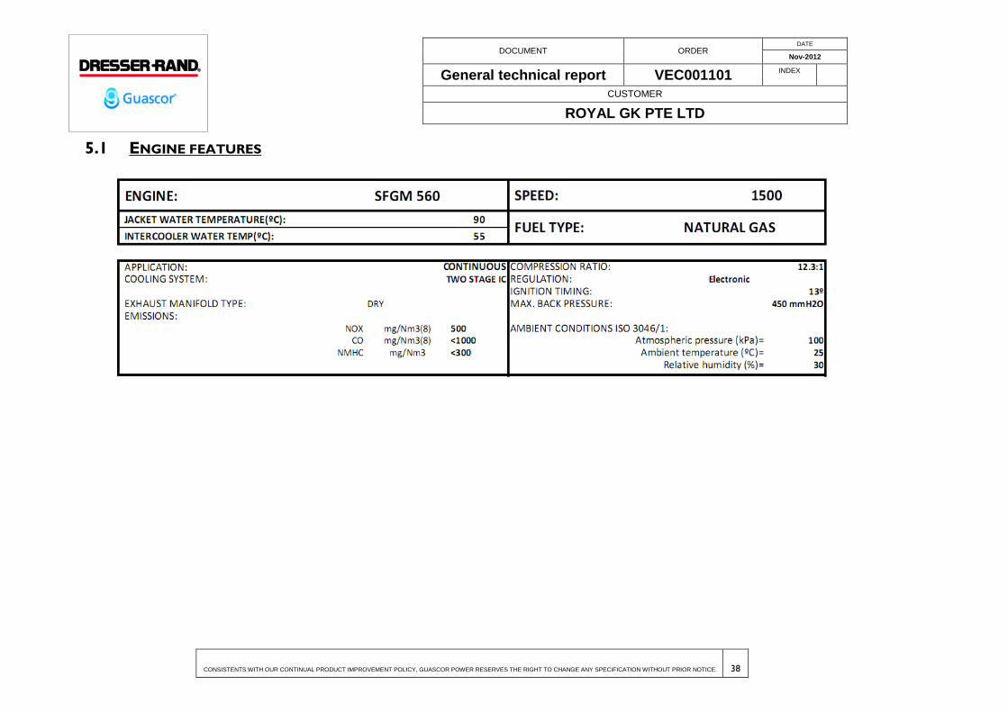
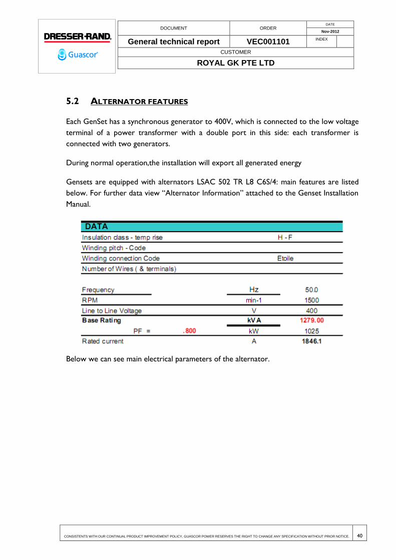
5.1 ENGINE FEATURES
DOCUMENT ORDER DATE
Nov-2012
General technical report VEC001101 INDEX
CUSTOMER
ROYAL GK PTE LTD
CONSISTENTS WITH OUR CONTINUAL PRODUCT IMPROVEMENT POLICY, GUASCOR POWER RESERVES THE RIGHT TO CHANGE ANY SPECIFICATION WITHOUT PRIOR NOTICE. 39
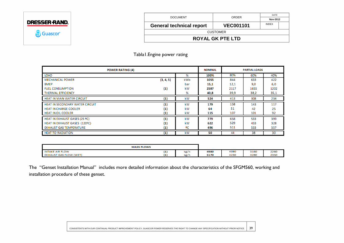
Tabla1.Engine power rating
The “Genset Installation Manual” includes more detailed information about the characteristics of the SFGM560, working and
installation procedure of these genset.
DOCUMENT ORDER DATE
Nov-2012
General technical report VEC001101 INDEX
CUSTOMER
ROYAL GK PTE LTD
CONSISTENTS WITH OUR CONTINUAL PRODUCT IMPROVEMENT POLICY, GUASCOR POWER RESERVES THE RIGHT TO CHANGE ANY SPECIFICATION WITHOUT PRIOR NOTICE. 40
5.2 ALTERNATOR FEATURES
Each GenSet has a synchronous generator to 400V, which is connected to the low voltage
terminal of a power transformer with a double port in this side: each transformer is
connected with two generators.
During normal operation,the installation will export all generated energy
Gensets are equipped with alternators LSAC 502 TR L8 C6S/4: main features are listed
below. For further data view “Alternator Information” attached to the Genset Installation
Manual.
Below we can see main electrical parameters of the alternator.

DOCUMENT ORDER DATE
Nov-2012
General technical report VEC001101 INDEX
CUSTOMER
ROYAL GK PTE LTD
CONSISTENTS WITH OUR CONTINUAL PRODUCT IMPROVEMENT POLICY, GUASCOR POWER RESERVES THE RIGHT TO CHANGE ANY SPECIFICATION WITHOUT PRIOR NOTICE. 41
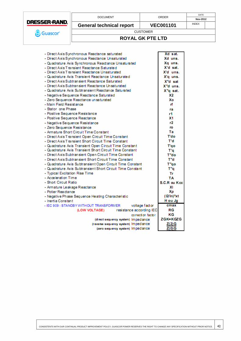
DOCUMENT ORDER DATE
Nov-2012
General technical report VEC001101 INDEX
CUSTOMER
ROYAL GK PTE LTD
CONSISTENTS WITH OUR CONTINUAL PRODUCT IMPROVEMENT POLICY, GUASCOR POWER RESERVES THE RIGHT TO CHANGE ANY SPECIFICATION WITHOUT PRIOR NOTICE. 42

DOCUMENT ORDER DATE
Nov-2012
General technical report VEC001101 INDEX
CUSTOMER
ROYAL GK PTE LTD
CONSISTENTS WITH OUR CONTINUAL PRODUCT IMPROVEMENT POLICY, GUASCOR POWER RESERVES THE RIGHT TO CHANGE ANY SPECIFICATION WITHOUT PRIOR NOTICE. 43
6 ENGINE FLUE SYSTEM
The function of this circuit is basically to conduct safely the exhaust gases from the engine
to the outside of the building. Exhaust gas flow from each genset is of 5170 kg/h at full
power with an estimated temperature of 496ºC. At partial load the exhaust temperature
may be over 550ºC
The pipes and elements of the circuit have been designed to allow the evacuation of these
exhaust gases keeping a maximum admissible exhaust backpressure of 450mm of water
column.
The document IT-C-A-40-001e of the genset installation manual describes the
requirements that a correct installation should fulfill.
Design of the engine flue system is described in the following drawings:
12-01: General Flow Diagram.
13-04: Exhaust Gases P&I diagram.
61-02 to 61-05: Lay out of pipes (exhaust circuit in pink color)
62-02: Lay-out of pipes genset area typical detail (the exhaust circuit is shown in
pink color)
63-21: Exhaust Pipes design.
51-01 to 51-06: Metallic structures for silencer and conduits support
The main elements of these circuits are:
U-3: the exhaust adapter commonly called “the trousers”, because it resembles
some trousers. It’s supplied with exhaust flexibles as loose item of the genset and
has to be installed at the engine exhaust connection.
U-4: the exhaust silencer. Also supplied as loose item of the genset. Regarding
engine flue circuit should be taken in consideration that there will be four “typical
layouts” with different pipeline designs. Type A (for genset 1), type B (for gensets
2 to 13), type C (for genset 14) and type D (for gensets 15 to 26).

DOCUMENT ORDER DATE
Nov-2012
General technical report VEC001101 INDEX
CUSTOMER
ROYAL GK PTE LTD
CONSISTENTS WITH OUR CONTINUAL PRODUCT IMPROVEMENT POLICY, GUASCOR POWER RESERVES THE RIGHT TO CHANGE ANY SPECIFICATION WITHOUT PRIOR NOTICE. 44
6.1 EXHAUST SILENCER
The pipeline for exhaust evacuation must be provided with a silencer (U-4 in the
drawings), which has the task of reduce the noise produced by the engine toward levels
allowed in current Standards.
Description of the exhaust silencer supplied by Guascor is included in the genset
installation manual. (view IC-C-D-40-002e and IT-O-A-2-001110-05e).
The exhaust silencers require supporting structures. These supporting structures are
shown in the drawings 51-01 to 51-06.
6.2 EXHAUST CHIMNEY
Exhaust line ends with vertical pipe protected from rain with a gate.
A sampling module has to be placed, according to current environmental standards, after
the silencer.
6.3 PIPING AND FITTINGS
Table 2.Exhaust chimney.
PIPE MATERIAL
SPECIFICATIONS
SPECIFICATIONS
Nº B10 Rev. 00
SERVICE: ExhaustGases (EG)
NOMINAL PRESSURE: PIPING MATERIAL: Stainless steel CORROSION PERMISSIBLE:
SERVICE LIMITS FROM: 0 bar; 20º C TO: 1 bar; +502ºC
ITEM SIZE
ENDS DESCRIPTION FROM TO
PIPE
150 250 BE
EN 1127
Seamless Pipe EN ISO 1127 thickness
2mm; Material EN 1.4301 (AISI 304)
300 400 BE Seamless Pipe EN ISO 1127 thickness
3mm; Material EN 1.4301 (AISI 304)
FLANGES 150 400 Type A
(FF)
Flange LJ EN 1092-1, type 02, face A PN10; Material
Group 4E0 EN 10216-2
FITTINGS 150 400 Beveled
Elbows, tee, reducer and cap carbon steel Seamless
EN 10253-3 material EN 1.4301 (304)
Other accessories: malleable iron threaded ASA
B16.11, material EN 1.4301 (304), thread s/EN

DOCUMENT ORDER DATE
Nov-2012
General technical report VEC001101 INDEX
CUSTOMER
ROYAL GK PTE LTD
CONSISTENTS WITH OUR CONTINUAL PRODUCT IMPROVEMENT POLICY, GUASCOR POWER RESERVES THE RIGHT TO CHANGE ANY SPECIFICATION WITHOUT PRIOR NOTICE. 45
PIPE MATERIAL
SPECIFICATIONS
SPECIFICATIONS
Nº B10 Rev. 00
SERVICE: ExhaustGases (EG)
NOMINAL PRESSURE: PIPING MATERIAL: Stainless steel CORROSION PERMISSIBLE:
SERVICE LIMITS FROM: 0 bar; 20º C TO: 1 bar; +502ºC
ITEM SIZE
ENDS DESCRIPTION FROM TO
10226
BOLTING
Screws EN 4014 (DIN931) Material Alloy Steel
quality 8.8
Nuts EN 4032 (DIN934) Material Alloy Steel quality
8.8
GASKET Gasket plate PN10 s/EN 1092; Asbestos free gasket
material like Klingersil 4430 or equivalent
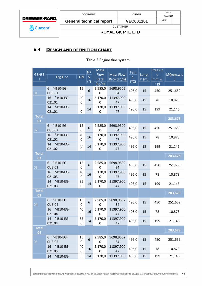
DOCUMENT ORDER DATE
Nov-2012
General technical report VEC001101 INDEX
CUSTOMER
ROYAL GK PTE LTD
CONSISTENTS WITH OUR CONTINUAL PRODUCT IMPROVEMENT POLICY, GUASCOR POWER RESERVES THE RIGHT TO CHANGE ANY SPECIFICATION WITHOUT PRIOR NOTICE. 46
6.4 DESIGN AND DEFINITION CHART
Table 3.Engine flue system.
GENSET
Tag Line DN NPS
(")
Mass Flow Rate
(kg/h)
Mass Flow Rate (Lb/h)
Temp.
(ºC)
Length (m)
Pressure
(mm.w.c g)
∆P(mm.w.c.)
01 6 "-B10-EG-0U3.01
150
6 2.585,0
0 5698,9502
34 496,0 15 450 251,659
16 "-B10-EG-021.01
400
16 5.170,0
0 11397,900
47 496,0 15 78 10,873
14 "-B10-EG-021.01
350
14 5.170,0
0 11397,900
47 496,0 15 199 21,146
Total 01
283,678
02 6 "-B10-EG-0U3.02
150
6 2.585,0
0 5698,9502
34 496,0 15 450 251,659
16 "-B10-EG-021.02
400
16 5.170,0
0 11397,900
47 496,0 15 78 10,873
14 "-B10-EG-021.02
350
14 5.170,0
0 11397,900
47 496,0 15 199 21,146
Total 02
283,678
03 6 "-B10-EG-0U3.03
150
6 2.585,0
0 5698,9502
34 496,0 15 450 251,659
16 "-B10-EG-021.03
400
16 5.170,0
0 11397,900
47 496,0 15 78 10,873
14 "-B10-EG-021.03
350
14 5.170,0
0 11397,900
47 496,0 15 199 21,146
Total 03
283,678
04 6 "-B10-EG-0U3.04
150
6 2.585,0
0 5698,9502
34 496,0 15 450 251,659
16 "-B10-EG-021.04
400
16 5.170,0
0 11397,900
47 496,0 15 78 10,873
14 "-B10-EG-021.04
350
14 5.170,0
0 11397,900
47 496,0 15 199 21,146
Total 04
283,678
05 6 "-B10-EG-0U3.05
150
6 2.585,0
0 5698,9502
34 496,0 15 450 251,659
16 "-B10-EG-021.05
400
16 5.170,0
0 11397,900
47 496,0 15 78 10,873
14 "-B10-EG- 35 14 5.170,0 11397,900 496,0 15 199 21,146

DOCUMENT ORDER DATE
Nov-2012
General technical report VEC001101 INDEX
CUSTOMER
ROYAL GK PTE LTD
CONSISTENTS WITH OUR CONTINUAL PRODUCT IMPROVEMENT POLICY, GUASCOR POWER RESERVES THE RIGHT TO CHANGE ANY SPECIFICATION WITHOUT PRIOR NOTICE. 47
GENSET
Tag Line DN NPS
(")
Mass Flow Rate
(kg/h)
Mass Flow Rate (Lb/h)
Temp.
(ºC)
Length (m)
Pressure
(mm.w.c g)
∆P(mm.w.c.)
021.05 0 0 47
Total 05
283,678
06 6 "-B10-EG-0U3.06
150
6 2.585,0
0 5698,9502
34 496,0 15 450 251,659
16 "-B10-EG-021.06
400
16 5.170,0
0 11397,900
47 496,0 15 78 10,873
14 "-B10-EG-021.06
350
14 5.170,0
0 11397,900
47 496,0 15 199 21,146
Total 06
283,678
07 6 "-B10-EG-0U3.07
150
6 2.585,0
0 5698,9502
34 496,0 15 450 251,659
16 "-B10-EG-021.07
400
16 5.170,0
0 11397,900
47 496,0 15 78 10,873
14 "-B10-EG-021.07
350
14 5.170,0
0 11397,900
47 496,0 15 199 21,146
Total 07
283,678
08 6 "-B10-EG-0U3.08
150
6 2.585,0
0 5698,9502
34 496,0 15 450 251,659
16 "-B10-EG-021.08
400
16 5.170,0
0 11397,900
47 496,0 15 78 10,873
14 "-B10-EG-021.08
350
14 5.170,0
0 11397,900
47 496,0 15 199 21,146
Total 08
283,678
09 6 "-B10-EG-0U3.09
150
6 2.585,0
0 5698,9502
34 496,0 15 450 251,659
16 "-B10-EG-021.09
400
16 5.170,0
0 11397,900
47 496,0 15 78 10,873
14 "-B10-EG-021.09
350
14 5.170,0
0 11397,900
47 496,0 15 199 21,146
Total 09
283,678
10 6 "-B10-EG-0U3.10
150
6 2.585,0
0 5698,9502
34 496,0 15 450 251,659
16 "-B10-EG-021.10
400
16 5.170,0
0 11397,900
47 496,0 15 78 10,873
14 "-B10-EG-021.10
350
14 5.170,0
0 11397,900
47 496,0 15 199 21,146
Total
283,678
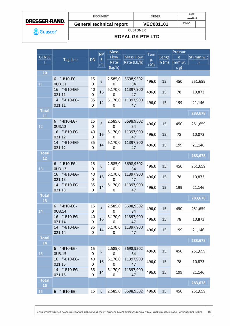
DOCUMENT ORDER DATE
Nov-2012
General technical report VEC001101 INDEX
CUSTOMER
ROYAL GK PTE LTD
CONSISTENTS WITH OUR CONTINUAL PRODUCT IMPROVEMENT POLICY, GUASCOR POWER RESERVES THE RIGHT TO CHANGE ANY SPECIFICATION WITHOUT PRIOR NOTICE. 48
GENSET
Tag Line DN NPS
(")
Mass Flow Rate
(kg/h)
Mass Flow Rate (Lb/h)
Temp.
(ºC)
Length (m)
Pressure
(mm.w.c g)
∆P(mm.w.c.)
10
11 6 "-B10-EG-0U3.11
150
6 2.585,0
0 5698,9502
34 496,0 15 450 251,659
16 "-B10-EG-021.11
400
16 5.170,0
0 11397,900
47 496,0 15 78 10,873
14 "-B10-EG-021.11
350
14 5.170,0
0 11397,900
47 496,0 15 199 21,146
Total 11
283,678
12 6 "-B10-EG-0U3.12
150
6 2.585,0
0 5698,9502
34 496,0 15 450 251,659
16 "-B10-EG-021.12
400
16 5.170,0
0 11397,900
47 496,0 15 78 10,873
14 "-B10-EG-021.12
350
14 5.170,0
0 11397,900
47 496,0 15 199 21,146
Total 12
283,678
13 6 "-B10-EG-0U3.13
150
6 2.585,0
0 5698,9502
34 496,0 15 450 251,659
16 "-B10-EG-021.13
400
16 5.170,0
0 11397,900
47 496,0 15 78 10,873
14 "-B10-EG-021.13
350
14 5.170,0
0 11397,900
47 496,0 15 199 21,146
Total 13
283,678
14 6 "-B10-EG-0U3.14
150
6 2.585,0
0 5698,9502
34 496,0 15 450 251,659
16 "-B10-EG-021.14
400
16 5.170,0
0 11397,900
47 496,0 15 78 10,873
14 "-B10-EG-021.14
350
14 5.170,0
0 11397,900
47 496,0 15 199 21,146
Total 14
283,678
15 6 "-B10-EG-0U3.15
150
6 2.585,0
0 5698,9502
34 496,0 15 450 251,659
16 "-B10-EG-021.15
400
16 5.170,0
0 11397,900
47 496,0 15 78 10,873
14 "-B10-EG-021.15
350
14 5.170,0
0 11397,900
47 496,0 15 199 21,146
Total 15
283,678
16 6 "-B10-EG- 15 6 2.585,0 5698,9502 496,0 15 450 251,659

DOCUMENT ORDER DATE
Nov-2012
General technical report VEC001101 INDEX
CUSTOMER
ROYAL GK PTE LTD
CONSISTENTS WITH OUR CONTINUAL PRODUCT IMPROVEMENT POLICY, GUASCOR POWER RESERVES THE RIGHT TO CHANGE ANY SPECIFICATION WITHOUT PRIOR NOTICE. 49
GENSET
Tag Line DN NPS
(")
Mass Flow Rate
(kg/h)
Mass Flow Rate (Lb/h)
Temp.
(ºC)
Length (m)
Pressure
(mm.w.c g)
∆P(mm.w.c.)
0U3.16 0 0 34
16 "-B10-EG-021.16
400
16 5.170,0
0 11397,900
47 496,0 15 78 10,873
14 "-B10-EG-021.16
350
14 5.170,0
0 11397,900
47 496,0 15 199 21,146
Total 16
283,678
17 6 "-B10-EG-0U3.17
150
6 2.585,0
0 5698,9502
34 496,0 15 450 251,659
16 "-B10-EG-021.17
400
16 5.170,0
0 11397,900
47 496,0 15 78 10,873
14 "-B10-EG-021.17
350
14 5.170,0
0 11397,900
47 496,0 15 199 21,146
Total 17
283,678
18 6 "-B10-EG-0U3.18
150
6 2.585,0
0 5698,9502
34 496,0 15 450 251,659
16 "-B10-EG-021.18
400
16 5.170,0
0 11397,900
47 496,0 15 78 10,873
14 "-B10-EG-021.18
350
14 5.170,0
0 11397,900
47 496,0 15 199 21,146
Total 18
283,678
19 6 "-B10-EG-0U3.19
150
6 2.585,0
0 5698,9502
34 496,0 15 450 251,659
16 "-B10-EG-021.19
400
16 5.170,0
0 11397,900
47 496,0 15 78 10,873
14 "-B10-EG-021.19
350
14 5.170,0
0 11397,900
47 496,0 15 199 21,146
Total 19
283,678
20 6 "-B10-EG-0U3.20
150
6 2.585,0
0 5698,9502
34 496,0 15 450 251,659
16 "-B10-EG-021.20
400
16 5.170,0
0 11397,900
47 496,0 15 78 10,873
14 "-B10-EG-021.20
350
14 5.170,0
0 11397,900
47 496,0 15 199 21,146
Total 20
283,678
21 6 "-B10-EG-0U3.21
150
6 2.585,0
0 5698,9502
34 496,0 15 450 251,659
16 "-B10-EG- 40 16 5.170,0 11397,900 496,0 15 78 10,873

DOCUMENT ORDER DATE
Nov-2012
General technical report VEC001101 INDEX
CUSTOMER
ROYAL GK PTE LTD
CONSISTENTS WITH OUR CONTINUAL PRODUCT IMPROVEMENT POLICY, GUASCOR POWER RESERVES THE RIGHT TO CHANGE ANY SPECIFICATION WITHOUT PRIOR NOTICE. 50
GENSET
Tag Line DN NPS
(")
Mass Flow Rate
(kg/h)
Mass Flow Rate (Lb/h)
Temp.
(ºC)
Length (m)
Pressure
(mm.w.c g)
∆P(mm.w.c.)
021.21 0 0 47
14 "-B10-EG-021.21
350
14 5.170,0
0 11397,900
47 496,0 15 199 21,146
Total 21
283,678
22 6 "-B10-EG-0U3.22
150
6 2.585,0
0 5698,9502
34 496,0 15 450 251,659
16 "-B10-EG-021.22
400
16 5.170,0
0 11397,900
47 496,0 15 78 10,873
14 "-B10-EG-021.22
350
14 5.170,0
0 11397,900
47 496,0 15 199 21,146
Total 22
283,678
23 6 "-B10-EG-0U3.23
150
6 2.585,0
0 5698,9502
34 496,0 15 450 251,659
16 "-B10-EG-021.23
400
16 5.170,0
0 11397,900
47 496,0 15 78 10,873
14 "-B10-EG-021.23
350
14 5.170,0
0 11397,900
47 496,0 15 199 21,146
Total 23
283,678
24 6 "-B10-EG-0U3.24
150
6 2.585,0
0 5698,9502
34 496,0 15 450 251,659
16 "-B10-EG-021.24
400
16 5.170,0
0 11397,900
47 496,0 15 78 10,873
14 "-B10-EG-021.24
350
14 5.170,0
0 11397,900
47 496,0 15 199 21,146
Total 24
283,678
25 6 "-B10-EG-0U3.25
150
6 2.585,0
0 5698,9502
34 496,0 15 450 251,659
16 "-B10-EG-021.25
400
16 5.170,0
0 11397,900
47 496,0 15 78 10,873
14 "-B10-EG-021.25
350
14 5.170,0
0 11397,900
47 496,0 15 199 21,146
Total 25
283,678
26 6 "-B10-EG-0U3.26
150
6 2.585,0
0 5698,9502
34 496,0 15 450 251,659
16 "-B10-EG-021.26
400
16 5.170,0
0 11397,900
47 496,0 15 78 10,873
14 "-B10-EG- 35 14 5.170,0 11397,900 496,0 15 199 21,146

DOCUMENT ORDER DATE
Nov-2012
General technical report VEC001101 INDEX
CUSTOMER
ROYAL GK PTE LTD
CONSISTENTS WITH OUR CONTINUAL PRODUCT IMPROVEMENT POLICY, GUASCOR POWER RESERVES THE RIGHT TO CHANGE ANY SPECIFICATION WITHOUT PRIOR NOTICE. 51
GENSET
Tag Line DN NPS
(")
Mass Flow Rate
(kg/h)
Mass Flow Rate (Lb/h)
Temp.
(ºC)
Length (m)
Pressure
(mm.w.c g)
∆P(mm.w.c.)
021.26 0 0 47
Total 26
283,678
The exhaust gas pipes are designed in the drawings 63-021.
DOCUMENT ORDER DATE
Nov-2012
General technical report VEC001101 INDEX
CUSTOMER
ROYAL GK PTE LTD
CONSISTENTS WITH OUR CONTINUAL PRODUCT IMPROVEMENT POLICY, GUASCOR POWER RESERVES THE RIGHT TO CHANGE ANY SPECIFICATION WITHOUT PRIOR NOTICE. 52
7 ENGINE COOLING SYSTEM
The function of this system is to dissipate the heat generated by engines internal
combustion while gensets are running. Treated water is used as coolant fluid. The
SFGM560 gensets have a double cooling circuit. A main high temperature (HT) circuit is
responsible for cooling most engine components. A second circuit with lower
temperature (LT) is used to cool the air/fuel mixture and the oil cooler.
In the case of a SFGM560 genset at full load the HT circuit needs to dissipate 524kW of
heat power while the LT circuit needs to dissipate 179kW. Design temperature for these
circuits is 90ºC for the HT and 55ºC for the LT circuits.
The document IT-C-A-20-003e of the genset installation manual describes general
information about the cooling system for Guascor engines.
In this project cooling is done by means of air coolers. The air coolers are from the
double core type, which allow with the same cooler to dissipate energy from two
independent circuits of different temperature. Electrical pumps will impulse the water
from the engine to the air coolers and back. The cooling system includes thus two
independent closed circuits filled with pressurized water.
The cooling water has to comply the requirements of the product information IO-C-M-
20-001e (Cooling Water Quality and Treatment).
Design of the engine cooling system is described in the following drawings:
12-01: General Flow Diagram.
13-01: Engine Cooling System P&I diagram. Note that in this drawing is shown the
scope of the “Pump set” or “Pump kit” already supplied and assembled from
Guascor factory.
60-02: Lay out of pipes section (cooling circuits in green colour)
61-02 to 61-05: Lay out of pipes (cooling circuits in green colour)
62-01: Lay-out of pipes air cooler typical detail (green colour)
62-02: Lay-out of pipes genset area typical detail (green colour)
63-01,-02: HT circuit pipes design.
63-04,-05: LT circuit pipes design.
The main elements of these circuit are:

DOCUMENT ORDER DATE
Nov-2012
General technical report VEC001101 INDEX
CUSTOMER
ROYAL GK PTE LTD
CONSISTENTS WITH OUR CONTINUAL PRODUCT IMPROVEMENT POLICY, GUASCOR POWER RESERVES THE RIGHT TO CHANGE ANY SPECIFICATION WITHOUT PRIOR NOTICE. 53
P-1/P-2: centrifugal pumps for the HT and LT circuits. These pumps will be
installed in a “Pump kit” that will be installed attached to genset bedplate. This kit
will be already supplied mounted from Guascor’s facilities. (in the first 8 gensets
supplied. the components of this kit will be supplied as loose items and have to be
mounted at factory. The drawing of this kit is included in the genset installation
manual (Ref. 40.20.E80))
TK-2/TK-3: Expansion vessels.
E-1: Air cooler.
7.1 ENGINEERING BASIS OF DESIGN
This project was completed in compliance with the following standards:
UNE-EN ISO 15607 Specification and qualification of welding procedures for
metallic materials
UNE-EN 287 Qualification test of welders
UNE-EN 25817 Arc-welded joints in steel. Guidance on quality levels for
imperfections (ISO 5817:1992).
UNE-EN ISO 13920 Welding. General tolerances for welded constructions.
Dimensions for lengths and angles. Shape and position. (ISO 13920:1996).
ASME Code
UNE-EN 10255 Non-Alloy steel tubes suitable for welding and threading -
Technical delivery conditions
UNE-EN 10216 Seamless steel tubes for pressure purposes - Technical delivery
conditions
UNE-EN ISO 1127 Stainless steel tubes. Dimensions, tolerances and conventional
masses per unit length

DOCUMENT ORDER DATE
Nov-2012
General technical report VEC001101 INDEX
CUSTOMER
ROYAL GK PTE LTD
CONSISTENTS WITH OUR CONTINUAL PRODUCT IMPROVEMENT POLICY, GUASCOR POWER RESERVES THE RIGHT TO CHANGE ANY SPECIFICATION WITHOUT PRIOR NOTICE. 54
7.2 ELECTRICAL WATER PUMPS
Water flowing through each cooling circuit is pumped with the following features:
1) Main water circuit or high temperature circuit (one per engine):
Type .................................................................................................. centrifugal
Motor drive ........................................................................................ electrical
Flow (m3/h) .................................................................................................... 70
Nominal temperature (ºC) ......................................................................... 90
2) Auxiliary water circuit or low temperature circuit (one per engine):
Type .................................................................................................. centrifugal
Motor drive ........................................................................................ electrical
Flow (m3/h).................................................................................................... 25
Nominal temperature (ºC) ......................................................................... 55
Information regarding the technical specifications and installation instructions of the
pumps are included in the genset installation manual, IT-C-A-20-011e (Installation
Manual), IC-G-D-20-067e (data sheet HT circuit water pump) and IC-G-D-20-066e. (data
sheet LT circuit water pump).
7.3 EXPANSION VESSELS
In each one of the two water circuits, is provided an expansion tank to support the
volume increase of water with the temperature variations.
1) Main water circuit or high temperature circuit (one per engine)::
Thermal load (kW) .................................................................................... 524
Static pressure (bar) ................................................................................... 2,2

DOCUMENT ORDER DATE
Nov-2012
General technical report VEC001101 INDEX
CUSTOMER
ROYAL GK PTE LTD
CONSISTENTS WITH OUR CONTINUAL PRODUCT IMPROVEMENT POLICY, GUASCOR POWER RESERVES THE RIGHT TO CHANGE ANY SPECIFICATION WITHOUT PRIOR NOTICE. 55
2) Secondary water circuit or low temperature circuit (one per engine):
Thermal load (kW) .................................................................................... 179
Static pressure (bar) ................................................................................... 2,2
The genset installation manual includes a document (IT-O-A-2-001110-07e) with the
expansion tank adaptation installation instructions.
7.3.1 Relief
In both cooling circuits, safety-relief valves will be installed at engine outlet, set to 3.5 bar
in order to ensure that this pressure is the maximum working pressure in these cooling
circuits.
7.4 DOUBLE CORE AIR COOLER
A double core air cooler will be installed in each engine to dissipate the heat input in main
and auxiliary cooling circuits and resulting from flue gases generated during engine
operation.
1. Type .................................................................................... Double core air cooler
2. Main circuit
i. Thermal load (kW) .................................................................. 524
ii. Flow (m3/h)................................................................................... 70
iii. Range of temperature (ºC) ................................................. 90/83
3. Auxiliary circuit
i. Thermal load (kW) .................................................................. 179
ii. Flow (m3/h)................................................................................... 25
iii. Range of temperature (ºC) ................................................. 62/55

DOCUMENT ORDER DATE
Nov-2012
General technical report VEC001101 INDEX
CUSTOMER
ROYAL GK PTE LTD
CONSISTENTS WITH OUR CONTINUAL PRODUCT IMPROVEMENT POLICY, GUASCOR POWER RESERVES THE RIGHT TO CHANGE ANY SPECIFICATION WITHOUT PRIOR NOTICE. 56
The genset installation manual includes following information regarding the air coolers:
IT-C-20-016e- Installation and user manual for Guascor standard dry-coolers.
76.73.625- Drawing of the supplied air coolers
IT-G-A-20-020e – User and installation manual for Standard air coolers. (TGR
model)
7.5 PIPING& FITTINGS
Table 4.Auxiliary circuit specification.
PIPE MATERIAL
SPECIFICATIONS
SPECIFICATIONS
Nº S01 Rev. 00
SERVICE: Cooling water (CW),
NOMINAL PRESSURE: PIPING MATERIAL: stainless steel CORROSION PERMISSIBLE:
SERVICE LIMITS FROM: 0 bar; 0º C TO: 9 bar; +120ºC
ITEM SIZE
ENDS DESCRIPTION FROM TO
PIPE 15 250 BE EN 1127
Seamless Pipe EN ISO 1127 thickness
2mm; Material EN 1.4301 (AISI 304)
FLANGES 32 250 Type A
(FF)
Flange LJ EN 1092-1, tipo 04, cara A PN10;
AluminumMaterial
FITTINGS 15 250 BE
Elbows, tee, reducer and cap carbon steel EN
10253-3; material EN 1.4301 (AISI 304).
Other accessories: malleable iron threaded ASA
B16.11, material AISI 304, thread s/EN 10226
BOLTING
Screws EN 4014 (DIN931) Alloy Steel Material
,quality 5.6
Nuts EN 4032 (DIN934) Alloy SteelMaterial quality
5.6
GASKET Gasket plat PN10 s/EN 1092; Asbestos-free gasket
material, Klingersil 4430 or equivalent

DOCUMENT ORDER DATE
Nov-2012
General technical report VEC001101 INDEX
CUSTOMER
ROYAL GK PTE LTD
CONSISTENTS WITH OUR CONTINUAL PRODUCT IMPROVEMENT POLICY, GUASCOR POWER RESERVES THE RIGHT TO CHANGE ANY SPECIFICATION WITHOUT PRIOR NOTICE. 57
PIPE MATERIAL
SPECIFICATIONS
SPECIFICATIONS
Nº S01 Rev. 00
SERVICE: Cooling water (CW),
NOMINAL PRESSURE: PIPING MATERIAL: stainless steel CORROSION PERMISSIBLE:
SERVICE LIMITS FROM: 0 bar; 0º C TO: 9 bar; +120ºC
ITEM SIZE
ENDS DESCRIPTION FROM TO
VA
LV
ES
BALL
15 25 female
thread Body and ball EN 10213-
4 1.4408 (316) Dimensions as EN 1983
2 pieces
Full bore
Drive lever 32 40 Flanged
Body cast iron EN-GJL-
250; stainless ball ;
length EN558-1 Series
27
BUTTERFLY
50 150
lug Dry Lever cast iron EN-GJL-
250; length EN558-1
Series 20 200 250
Manual wheel type
(Reduction gear operate )
CHECK
15 40 Wafer disk Cast iron EN-GJL-250 disk
andstainless spring
50 250 Wafer Dual plate Body and plates cast iron EN_GJL-
250; Length EN558-1 series 16
Table 5.Main circuit specification.
PIPE MATERIAL
SPECIFICATIONS
SPECIFICATIONS
Nº A10 Rev. 00
SERVICE: Natural Gas (NG)& Cooling Watert (CW)
NOMINAL PRESSURE: PIPING MATERIAL: Carbon Steel
CORROSION PERMISSIBLE:
SERVICE LIMITS FROM: 0 bar; 0º C TO: 9 bar; +120ºC
ITEM SIZE DN (mm)
ENDS DESCRIPTION FROM TO
PIPE
15 40 PE EN 10255
(DIN 2440)
Seamless Pipe EN 10255 medium
series M; Material EN 1.0026 S195T
50 250 BE EN 10216
(DIN 2448)
Seamless Pipe EN 10216-2 series 1
normalized thickness; Material
P235GH EN 1.0254
FLANGES 32 250 Type A
(FF)
Flange SW EN 1092-1, type 01, face A PN10;
Material P235GH EN 10216-2
FITTINGS 15 250 Beveled
Elbows, tee, reducer and cap carbon seamless steel
EN 10253-1 material EN P235TR1 (st 37).
Other accessories: malleable iron threaded ASA
B16.11, material A-105, thread s/EN 10226

DOCUMENT ORDER DATE
Nov-2012
General technical report VEC001101 INDEX
CUSTOMER
ROYAL GK PTE LTD
CONSISTENTS WITH OUR CONTINUAL PRODUCT IMPROVEMENT POLICY, GUASCOR POWER RESERVES THE RIGHT TO CHANGE ANY SPECIFICATION WITHOUT PRIOR NOTICE. 58
PIPE MATERIAL
SPECIFICATIONS
SPECIFICATIONS
Nº A10 Rev. 00
SERVICE: Natural Gas (NG)& Cooling Watert (CW)
NOMINAL PRESSURE: PIPING MATERIAL: Carbon Steel
CORROSION PERMISSIBLE:
SERVICE LIMITS FROM: 0 bar; 0º C TO: 9 bar; +120ºC
ITEM SIZE DN (mm)
ENDS DESCRIPTION FROM TO
BOLTING
Screws EN 4014 (DIN931) Alloy SteelMaterial,
quality 5.6
Nuts EN 4032 (DIN934) Alloy Steel Material,
quality 5.6
GASKET Gasket plate PN10 s/EN 1092; Asbestos free gasket
material like Klingersil 4430 or equivalent.

DOCUMENT ORDER DATE
Nov-2012
General technical report VEC001101 INDEX
CUSTOMER
ROYAL GK PTE LTD
CONSISTENTS WITH OUR CONTINUAL PRODUCT IMPROVEMENT POLICY, GUASCOR POWER RESERVES THE RIGHT TO CHANGE ANY SPECIFICATION WITHOUT PRIOR NOTICE. 59
PIPE MATERIAL
SPECIFICATIONS
SPECIFICATIONS
Nº A10 Rev. 00
SERVICE: Natural Gas (NG)& Cooling Watert (CW)
NOMINAL PRESSURE: PIPING MATERIAL: Carbon Steel
CORROSION PERMISSIBLE:
SERVICE LIMITS FROM: 0 bar; 0º C TO: 9 bar; +120ºC
ITEM SIZE DN (mm)
ENDS DESCRIPTION FROM TO
VA
LV
ES
BALL
15 25 female
thread Body and ball EN 10213-
4 1.4408 (316) Dimensions as EN 1983
2 pieces
Full bore
Drive lever 32 40 Flanged
Body cast iron EN-GJL-
250; ball inox. ; length
EN558-1 Series 27
BUTTERFLY
50 150
lug Dry Lever cast iron EN-GJL-
250; length EN558-1
Series 20 200 250
Manual wheel type
(Reduction gear operate )
CHECK
15 40 Wafer disk Cast iron EN-GJL-250 disk
andstainless spring.
50 250 Wafer Dual plate Body and plates cast iron EN_GJL-
250; Length EN558-1 series 16
FILTERS
15 25 female
thread
Tipe Y
Cast iron EN_GJL-250, sieve steel.
32 150 Flanged
Body cast iron EN_GJL-250,
Stainless Sieve; Length EN558-1
series 1
7.6 TESTING & INSPECTION
For the final acceptance of the in site assembly of pipelines installations, a hydraulic
pressure test is needed, considering each circuit as whole system. Test pressure will be
1.5 times the design pressure.
Before the hydrostatic test, equipment will be isolated in flanges using all the needed
elements for it(by-pass, closures, blind flanges, gaskets, etc..)
After pressure test, there will be a final cleaning of pipes, inside and outside of each one.
Once the hydrostatic test has finished, installation will be emptied in order to remove
metallic chips and dirt in line. Finally, before proceeding to final filling of each hydraulic
circuit, water is circulated by pumps, with basket filters placed at the entrance of each
equipment to protect them (one per pump, exchanger, genset, expansion tank, etc.).
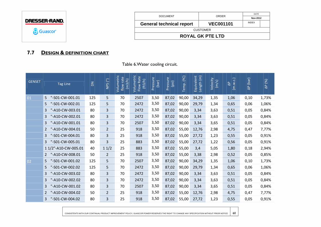
DOCUMENT ORDER DATE
Nov-2012
General technical report VEC001101 INDEX
CUSTOMER
ROYAL GK PTE LTD
CONSISTENTS WITH OUR CONTINUAL PRODUCT IMPROVEMENT POLICY, GUASCOR POWER RESERVES THE RIGHT TO CHANGE ANY SPECIFICATION WITHOUT PRIOR NOTICE. 60
7.7 DESIGN & DEFINITION CHART
Table 6.Water cooling circuit.
GENSET Tag Line D
N
NP
S ("
)
Vo
lum
etri
c
flo
w r
ate
(m3
/h)
Vo
lum
etri
c
Flo
w R
ate
(ft3
/h)
Pre
ssu
re
(bar
)
Pre
ssu
re
(psi
)
Tem
p. (
ºC)
Equ
ival
ent
Len
gth
(m
)
Vel
oci
ty
(m/s
)
∆P
(m.w
.c.)
∆P
(b
ar)
∆P
(%
)
01 5 "-S01-CW-001.01 125 5 70 2507 3,50 87,02 90,00 34,29 1,35 1,06 0,10 1,73%
5 "-S01-CW-002.01 125 5 70 2472 3,50 87,02 90,00 29,79 1,34 0,65 0,06 1,06%
3 "-A10-CW-003.01 80 3 70 2472 3,50 87,02 90,00 3,34 3,63 0,51 0,05 0,84%
3 "-A10-CW-002.01 80 3 70 2472 3,50 87,02 90,00 3,34 3,63 0,51 0,05 0,84%
3 "-A10-CW-001.01 80 3 70 2507 3,50 87,02 90,00 3,34 3,65 0,51 0,05 0,84%
2 "-A10-CW-004.01 50 2 25 918 3,50 87,02 55,00 12,76 2,98 4,75 0,47 7,77%
3 "-S01-CW-004.01 80 3 25 918 3,50 87,02 55,00 27,72 1,23 0,55 0,05 0,91%
3 "-S01-CW-005.01 80 3 25 883 3,50 87,02 55,00 27,72 1,22 0,56 0,05 0,91%
1 1/2"-A10-CW-005.01 40 1 1/2 25 883 3,50 87,02 55,00 3,4 5,05 1,80 0,18 2,94%
2 "-A10-CW-008.01 50 2 25 918 3,50 87,02 55,00 3,38 2,98 0,52 0,05 0,85%
02 5 "-S01-CW-001.02 125 5 70 2507 3,50 87,02 90,00 34,29 1,35 1,06 0,10 1,73%
5 "-S01-CW-002.02 125 5 70 2472 3,50 87,02 90,00 29,79 1,34 0,65 0,06 1,06%
3 "-A10-CW-003.02 80 3 70 2472 3,50 87,02 90,00 3,34 3,63 0,51 0,05 0,84%
3 "-A10-CW-002.02 80 3 70 2472 3,50 87,02 90,00 3,34 3,63 0,51 0,05 0,84%
3 "-A10-CW-001.02 80 3 70 2507 3,50 87,02 90,00 3,34 3,65 0,51 0,05 0,84%
2 "-A10-CW-004.02 50 2 25 918 3,50 87,02 55,00 12,76 2,98 4,75 0,47 7,77%
3 "-S01-CW-004.02 80 3 25 918 3,50 87,02 55,00 27,72 1,23 0,55 0,05 0,91%

DOCUMENT ORDER DATE
Nov-2012
General technical report VEC001101 INDEX
CUSTOMER
ROYAL GK PTE LTD
CONSISTENTS WITH OUR CONTINUAL PRODUCT IMPROVEMENT POLICY, GUASCOR POWER RESERVES THE RIGHT TO CHANGE ANY SPECIFICATION WITHOUT PRIOR NOTICE. 61
GENSET Tag Line D
N
NP
S ("
)
Vo
lum
etri
c
flo
w r
ate
(m3
/h)
Vo
lum
etri
c
Flo
w R
ate
(ft3
/h)
Pre
ssu
re
(bar
)
Pre
ssu
re
(psi
)
Tem
p. (
ºC)
Equ
ival
ent
Len
gth
(m
)
Vel
oci
ty
(m/s
)
∆P
(m.w
.c.)
∆P
(b
ar)
∆P
(%
)
3 "-S01-CW-005.02 80 3 25 883 3,50 87,02 55,00 27,72 1,22 0,56 0,05 0,91%
1 1/2"-A10-CW-005.02 40 1 1/2 25 883 3,50 87,02 55,00 3,4 5,05 1,80 0,18 2,94%
2 "-A10-CW-008.02 50 2 25 918 3,50 87,02 55,00 3,38 2,98 0,52 0,05 0,85%
03 5 "-S01-CW-001.03 125 5 70 2507 3,50 87,02 90,00 34,29 1,35 1,06 0,10 1,73%
5 "-S01-CW-002.03 125 5 70 2472 3,50 87,02 90,00 29,79 1,34 0,65 0,06 1,06%
3 "-A10-CW-003.03 80 3 70 2472 3,50 87,02 90,00 3,34 3,63 0,51 0,05 0,84%
3 "-A10-CW-002.03 80 3 70 2472 3,50 87,02 90,00 3,34 3,63 0,51 0,05 0,84%
3 "-A10-CW-001.03 80 3 70 2507 3,50 87,02 90,00 3,34 3,65 0,51 0,05 0,84%
2 "-A10-CW-004.03 50 2 25 918 3,50 87,02 55,00 12,76 2,98 4,75 0,47 7,77%
3 "-S01-CW-004.03 80 3 25 918 3,50 87,02 55,00 27,72 1,23 0,55 0,05 0,91%
3 "-S01-CW-005.03 80 3 25 883 3,50 87,02 55,00 27,72 1,22 0,56 0,05 0,91%
1 1/2"-A10-CW-005.03 40 1 1/2 25 883 3,50 87,02 55,00 3,4 5,05 1,80 0,18 2,94%
2 "-A10-CW-008.03 50 2 25 918 3,50 87,02 55,00 3,38 2,98 0,52 0,05 0,85%
04 5 "-S01-CW-001.04 125 5 70 2507 3,50 87,02 90,00 34,29 1,35 1,06 0,10 1,73%
5 "-S01-CW-002.04 125 5 70 2472 3,50 87,02 90,00 29,79 1,34 0,65 0,06 1,06%
3 "-A10-CW-003.04 80 3 70 2472 3,50 87,02 90,00 3,34 3,63 0,51 0,05 0,84%
3 "-A10-CW-002.04 80 3 70 2472 3,50 87,02 90,00 3,34 3,63 0,51 0,05 0,84%
3 "-A10-CW-001.04 80 3 70 2507 3,50 87,02 90,00 3,34 3,65 0,51 0,05 0,84%
2 "-A10-CW-004.04 50 2 25 918 3,50 87,02 55,00 12,76 2,98 4,75 0,47 7,77%
3 "-S01-CW-004.04 80 3 25 918 3,50 87,02 55,00 27,72 1,23 0,55 0,05 0,91%
3 "-S01-CW-005.04 80 3 25 883 3,50 87,02 55,00 27,72 1,22 0,56 0,05 0,91%

DOCUMENT ORDER DATE
Nov-2012
General technical report VEC001101 INDEX
CUSTOMER
ROYAL GK PTE LTD
CONSISTENTS WITH OUR CONTINUAL PRODUCT IMPROVEMENT POLICY, GUASCOR POWER RESERVES THE RIGHT TO CHANGE ANY SPECIFICATION WITHOUT PRIOR NOTICE. 62
GENSET Tag Line D
N
NP
S ("
)
Vo
lum
etri
c
flo
w r
ate
(m3
/h)
Vo
lum
etri
c
Flo
w R
ate
(ft3
/h)
Pre
ssu
re
(bar
)
Pre
ssu
re
(psi
)
Tem
p. (
ºC)
Equ
ival
ent
Len
gth
(m
)
Vel
oci
ty
(m/s
)
∆P
(m.w
.c.)
∆P
(b
ar)
∆P
(%
)
1 1/2"-A10-CW-005.04 40 1 1/2 25 883 3,50 87,02 55,00 3,4 5,05 1,80 0,18 2,94%
2 "-A10-CW-008.04 50 2 25 918 3,50 87,02 55,00 3,38 2,98 0,52 0,05 0,85%
05 5 "-S01-CW-001.05 125 5 70 2507 3,50 87,02 90,00 34,29 1,35 1,06 0,10 1,73%
5 "-S01-CW-002.05 125 5 70 2472 3,50 87,02 90,00 29,79 1,34 0,65 0,06 1,06%
3 "-A10-CW-003.05 80 3 70 2472 3,50 87,02 90,00 3,34 3,63 0,51 0,05 0,84%
3 "-A10-CW-002.05 80 3 70 2472 3,50 87,02 90,00 3,34 3,63 0,51 0,05 0,84%
3 "-A10-CW-001.05 80 3 70 2507 3,50 87,02 90,00 3,34 3,65 0,51 0,05 0,84%
2 "-A10-CW-004.05 50 2 25 918 3,50 87,02 55,00 12,76 2,98 4,75 0,47 7,77%
3 "-S01-CW-004.05 80 3 25 918 3,50 87,02 55,00 27,72 1,23 0,55 0,05 0,91%
3 "-S01-CW-005.05 80 3 25 883 3,50 87,02 55,00 27,72 1,22 0,56 0,05 0,91%
1 1/2"-A10-CW-005.05 40 1 1/2 25 883 3,50 87,02 55,00 3,4 5,05 1,80 0,18 2,94%
2 "-A10-CW-008.05 50 2 25 918 3,50 87,02 55,00 3,38 2,98 0,52 0,05 0,85%
06 5 "-S01-CW-001.06 125 5 70 2507 3,50 87,02 90,00 34,29 1,35 1,06 0,10 1,73%
5 "-S01-CW-002.06 125 5 70 2472 3,50 87,02 90,00 29,79 1,34 0,65 0,06 1,06%
3 "-A10-CW-003.06 80 3 70 2472 3,50 87,02 90,00 3,34 3,63 0,51 0,05 0,84%
3 "-A10-CW-002.06 80 3 70 2472 3,50 87,02 90,00 3,34 3,63 0,51 0,05 0,84%
3 "-A10-CW-001.06 80 3 70 2507 3,50 87,02 90,00 3,34 3,65 0,51 0,05 0,84%
2 "-A10-CW-004.06 50 2 25 918 3,50 87,02 55,00 12,76 2,98 4,75 0,47 7,77%
3 "-S01-CW-004.06 80 3 25 918 3,50 87,02 55,00 27,72 1,23 0,55 0,05 0,91%
3 "-S01-CW-005.06 80 3 25 883 3,50 87,02 55,00 27,72 1,22 0,56 0,05 0,91%
1 1/2"-A10-CW-005.06 40 1 1/2 25 883 3,50 87,02 55,00 3,4 5,05 1,80 0,18 2,94%

DOCUMENT ORDER DATE
Nov-2012
General technical report VEC001101 INDEX
CUSTOMER
ROYAL GK PTE LTD
CONSISTENTS WITH OUR CONTINUAL PRODUCT IMPROVEMENT POLICY, GUASCOR POWER RESERVES THE RIGHT TO CHANGE ANY SPECIFICATION WITHOUT PRIOR NOTICE. 63
GENSET Tag Line D
N
NP
S ("
)
Vo
lum
etri
c
flo
w r
ate
(m3
/h)
Vo
lum
etri
c
Flo
w R
ate
(ft3
/h)
Pre
ssu
re
(bar
)
Pre
ssu
re
(psi
)
Tem
p. (
ºC)
Equ
ival
ent
Len
gth
(m
)
Vel
oci
ty
(m/s
)
∆P
(m.w
.c.)
∆P
(b
ar)
∆P
(%
)
2 "-A10-CW-008.06 50 2 25 918 3,50 87,02 55,00 3,38 2,98 0,52 0,05 0,85%
07 5 "-S01-CW-001.07 125 5 70 2507 3,50 87,02 90,00 34,29 1,35 1,06 0,10 1,73%
5 "-S01-CW-002.07 125 5 70 2472 3,50 87,02 90,00 29,79 1,34 0,65 0,06 1,06%
3 "-A10-CW-003.07 80 3 70 2472 3,50 87,02 90,00 3,34 3,63 0,51 0,05 0,84%
3 "-A10-CW-002.07 80 3 70 2472 3,50 87,02 90,00 3,34 3,63 0,51 0,05 0,84%
3 "-A10-CW-001.07 80 3 70 2507 3,50 87,02 90,00 3,34 3,65 0,51 0,05 0,84%
2 "-A10-CW-004.07 50 2 25 918 3,50 87,02 55,00 12,76 2,98 4,75 0,47 7,77%
3 "-S01-CW-004.07 80 3 25 918 3,50 87,02 55,00 27,72 1,23 0,55 0,05 0,91%
3 "-S01-CW-005.07 80 3 25 883 3,50 87,02 55,00 27,72 1,22 0,56 0,05 0,91%
1 1/2"-A10-CW-005.07 40 1 1/2 25 883 3,50 87,02 55,00 3,4 5,05 1,80 0,18 2,94%
2 "-A10-CW-008.07 50 2 25 918 3,50 87,02 55,00 3,38 2,98 0,52 0,05 0,85%
08 5 "-S01-CW-001.08 125 5 70 2507 3,50 87,02 90,00 34,29 1,35 1,06 0,10 1,73%
5 "-S01-CW-002.08 125 5 70 2472 3,50 87,02 90,00 29,79 1,34 0,65 0,06 1,06%
3 "-A10-CW-003.08 80 3 70 2472 3,50 87,02 90,00 3,34 3,63 0,51 0,05 0,84%
3 "-A10-CW-002.08 80 3 70 2472 3,50 87,02 90,00 3,34 3,63 0,51 0,05 0,84%
3 "-A10-CW-001.08 80 3 70 2507 3,50 87,02 90,00 3,34 3,65 0,51 0,05 0,84%
2 "-A10-CW-004.08 50 2 25 918 3,50 87,02 55,00 12,76 2,98 4,75 0,47 7,77%
3 "-S01-CW-004.08 80 3 25 918 3,50 87,02 55,00 27,72 1,23 0,55 0,05 0,91%
3 "-S01-CW-005.08 80 3 25 883 3,50 87,02 55,00 27,72 1,22 0,56 0,05 0,91%
1 1/2"-A10-CW-005.08 40 1 1/2 25 883 3,50 87,02 55,00 3,4 5,05 1,80 0,18 2,94%
2 "-A10-CW-008.08 50 2 25 918 3,50 87,02 55,00 3,38 2,98 0,52 0,05 0,85%

DOCUMENT ORDER DATE
Nov-2012
General technical report VEC001101 INDEX
CUSTOMER
ROYAL GK PTE LTD
CONSISTENTS WITH OUR CONTINUAL PRODUCT IMPROVEMENT POLICY, GUASCOR POWER RESERVES THE RIGHT TO CHANGE ANY SPECIFICATION WITHOUT PRIOR NOTICE. 64
GENSET Tag Line D
N
NP
S ("
)
Vo
lum
etri
c
flo
w r
ate
(m3
/h)
Vo
lum
etri
c
Flo
w R
ate
(ft3
/h)
Pre
ssu
re
(bar
)
Pre
ssu
re
(psi
)
Tem
p. (
ºC)
Equ
ival
ent
Len
gth
(m
)
Vel
oci
ty
(m/s
)
∆P
(m.w
.c.)
∆P
(b
ar)
∆P
(%
)
09 5 "-S01-CW-001.09 125 5 70 2507 3,50 87,02 90,00 34,29 1,35 1,06 0,10 1,73%
5 "-S01-CW-002.09 125 5 70 2472 3,50 87,02 90,00 29,79 1,34 0,65 0,06 1,06%
3 "-A10-CW-003.09 80 3 70 2472 3,50 87,02 90,00 3,34 3,63 0,51 0,05 0,84%
3 "-A10-CW-002.09 80 3 70 2472 3,50 87,02 90,00 3,34 3,63 0,51 0,05 0,84%
3 "-A10-CW-001.09 80 3 70 2507 3,50 87,02 90,00 3,34 3,65 0,51 0,05 0,84%
2 "-A10-CW-004.09 50 2 25 918 3,50 87,02 55,00 12,76 2,98 4,75 0,47 7,77%
3 "-S01-CW-004.09 80 3 25 918 3,50 87,02 55,00 27,72 1,23 0,55 0,05 0,91%
3 "-S01-CW-005.09 80 3 25 883 3,50 87,02 55,00 27,72 1,22 0,56 0,05 0,91%
1 1/2"-A10-CW-005.09 40 1 1/2 25 883 3,50 87,02 55,00 3,4 5,05 1,80 0,18 2,94%
2 "-A10-CW-008.09 50 2 25 918 3,50 87,02 55,00 3,38 2,98 0,52 0,05 0,85%
10 5 "-S01-CW-001.10 125 5 70 2507 3,50 87,02 90,00 34,29 1,35 1,06 0,10 1,73%
5 "-S01-CW-002.10 125 5 70 2472 3,50 87,02 90,00 29,79 1,34 0,65 0,06 1,06%
3 "-A10-CW-003.10 80 3 70 2472 3,50 87,02 90,00 3,34 3,63 0,51 0,05 0,84%
3 "-A10-CW-002.10 80 3 70 2472 3,50 87,02 90,00 3,34 3,63 0,51 0,05 0,84%
3 "-A10-CW-001.10 80 3 70 2507 3,50 87,02 90,00 3,34 3,65 0,51 0,05 0,84%
2 "-A10-CW-004.10 50 2 25 918 3,50 87,02 55,00 12,76 2,98 4,75 0,47 7,77%
3 "-S01-CW-004.10 80 3 25 918 3,50 87,02 55,00 27,72 1,23 0,55 0,05 0,91%
3 "-S01-CW-005.10 80 3 25 883 3,50 87,02 55,00 27,72 1,22 0,56 0,05 0,91%
1 1/2"-A10-CW-005.10 40 1 1/2 25 883 3,50 87,02 55,00 3,4 5,05 1,80 0,18 2,94%
2 "-A10-CW-008.10 50 2 25 918 3,50 87,02 55,00 3,38 2,98 0,52 0,05 0,85%
11 5 "-S01-CW-001.11 125 5 70 2507 3,50 87,02 90,00 34,29 1,35 1,06 0,10 1,73%

DOCUMENT ORDER DATE
Nov-2012
General technical report VEC001101 INDEX
CUSTOMER
ROYAL GK PTE LTD
CONSISTENTS WITH OUR CONTINUAL PRODUCT IMPROVEMENT POLICY, GUASCOR POWER RESERVES THE RIGHT TO CHANGE ANY SPECIFICATION WITHOUT PRIOR NOTICE. 65
GENSET Tag Line D
N
NP
S ("
)
Vo
lum
etri
c
flo
w r
ate
(m3
/h)
Vo
lum
etri
c
Flo
w R
ate
(ft3
/h)
Pre
ssu
re
(bar
)
Pre
ssu
re
(psi
)
Tem
p. (
ºC)
Equ
ival
ent
Len
gth
(m
)
Vel
oci
ty
(m/s
)
∆P
(m.w
.c.)
∆P
(b
ar)
∆P
(%
)
5 "-S01-CW-002.11 125 5 70 2472 3,50 87,02 90,00 29,79 1,34 0,65 0,06 1,06%
3 "-A10-CW-003.11 80 3 70 2472 3,50 87,02 90,00 3,34 3,63 0,51 0,05 0,84%
3 "-A10-CW-002.11 80 3 70 2472 3,50 87,02 90,00 3,34 3,63 0,51 0,05 0,84%
3 "-A10-CW-001.11 80 3 70 2507 3,50 87,02 90,00 3,34 3,65 0,51 0,05 0,84%
2 "-A10-CW-004.11 50 2 25 918 3,50 87,02 55,00 12,76 2,98 4,75 0,47 7,77%
3 "-S01-CW-004.11 80 3 25 918 3,50 87,02 55,00 27,72 1,23 0,55 0,05 0,91%
3 "-S01-CW-005.11 80 3 25 883 3,50 87,02 55,00 27,72 1,22 0,56 0,05 0,91%
1 1/2"-A10-CW-005.11 40 1 1/2 25 883 3,50 87,02 55,00 3,4 5,05 1,80 0,18 2,94%
2 "-A10-CW-008.11 50 2 25 918 3,50 87,02 55,00 3,38 2,98 0,52 0,05 0,85%
12 5 "-S01-CW-001.12 125 5 70 2507 3,50 87,02 90,00 34,29 1,35 1,06 0,10 1,73%
5 "-S01-CW-002.12 125 5 70 2472 3,50 87,02 90,00 29,79 1,34 0,65 0,06 1,06%
3 "-A10-CW-003.12 80 3 70 2472 3,50 87,02 90,00 3,34 3,63 0,51 0,05 0,84%
3 "-A10-CW-002.12 80 3 70 2472 3,50 87,02 90,00 3,34 3,63 0,51 0,05 0,84%
3 "-A10-CW-001.12 80 3 70 2507 3,50 87,02 90,00 3,34 3,65 0,51 0,05 0,84%
2 "-A10-CW-004.12 50 2 25 918 3,50 87,02 55,00 12,76 2,98 4,75 0,47 7,77%
3 "-S01-CW-004.12 80 3 25 918 3,50 87,02 55,00 27,72 1,23 0,55 0,05 0,91%
3 "-S01-CW-005.12 80 3 25 883 3,50 87,02 55,00 27,72 1,22 0,56 0,05 0,91%
1 1/2"-A10-CW-005.12 40 1 1/2 25 883 3,50 87,02 55,00 3,4 5,05 1,80 0,18 2,94%
2 "-A10-CW-008.12 50 2 25 918 3,50 87,02 55,00 3,38 2,98 0,52 0,05 0,85%
13 5 "-S01-CW-001.13 125 5 70 2507 3,50 87,02 90,00 34,29 1,35 1,06 0,10 1,73%
5 "-S01-CW-002.13 125 5 70 2472 3,50 87,02 90,00 29,79 1,34 0,65 0,06 1,06%

DOCUMENT ORDER DATE
Nov-2012
General technical report VEC001101 INDEX
CUSTOMER
ROYAL GK PTE LTD
CONSISTENTS WITH OUR CONTINUAL PRODUCT IMPROVEMENT POLICY, GUASCOR POWER RESERVES THE RIGHT TO CHANGE ANY SPECIFICATION WITHOUT PRIOR NOTICE. 66
GENSET Tag Line D
N
NP
S ("
)
Vo
lum
etri
c
flo
w r
ate
(m3
/h)
Vo
lum
etri
c
Flo
w R
ate
(ft3
/h)
Pre
ssu
re
(bar
)
Pre
ssu
re
(psi
)
Tem
p. (
ºC)
Equ
ival
ent
Len
gth
(m
)
Vel
oci
ty
(m/s
)
∆P
(m.w
.c.)
∆P
(b
ar)
∆P
(%
)
3 "-A10-CW-003.13 80 3 70 2472 3,50 87,02 90,00 3,34 3,63 0,51 0,05 0,84%
3 "-A10-CW-002.13 80 3 70 2472 3,50 87,02 90,00 3,34 3,63 0,51 0,05 0,84%
3 "-A10-CW-001.13 80 3 70 2507 3,50 87,02 90,00 3,34 3,65 0,51 0,05 0,84%
2 "-A10-CW-004.13 50 2 25 918 3,50 87,02 55,00 12,76 2,98 4,75 0,47 7,77%
3 "-S01-CW-004.13 80 3 25 918 3,50 87,02 55,00 27,72 1,23 0,55 0,05 0,91%
3 "-S01-CW-005.13 80 3 25 883 3,50 87,02 55,00 27,72 1,22 0,56 0,05 0,91%
1 1/2"-A10-CW-005.13 40 1 1/2 25 883 3,50 87,02 55,00 3,4 5,05 1,80 0,18 2,94%
2 "-A10-CW-008.13 50 2 25 918 3,50 87,02 55,00 3,38 2,98 0,52 0,05 0,85%
14 5 "-S01-CW-001.14 125 5 70 2507 3,50 87,02 90,00 34,29 1,35 1,06 0,10 1,73%
5 "-S01-CW-002.14 125 5 70 2472 3,50 87,02 90,00 29,79 1,34 0,65 0,06 1,06%
3 "-A10-CW-003.14 80 3 70 2472 3,50 87,02 90,00 3,34 3,63 0,51 0,05 0,84%
3 "-A10-CW-002.14 80 3 70 2472 3,50 87,02 90,00 3,34 3,63 0,51 0,05 0,84%
3 "-A10-CW-001.14 80 3 70 2507 3,50 87,02 90,00 3,34 3,65 0,51 0,05 0,84%
2 "-A10-CW-004.14 50 2 25 918 3,50 87,02 55,00 12,76 2,98 4,75 0,47 7,77%
3 "-S01-CW-004.14 80 3 25 918 3,50 87,02 55,00 27,72 1,23 0,55 0,05 0,91%
3 "-S01-CW-005.14 80 3 25 883 3,50 87,02 55,00 27,72 1,22 0,56 0,05 0,91%
1 1/2"-A10-CW-005.14 40 1 1/2 25 883 3,50 87,02 55,00 3,4 5,05 1,80 0,18 2,94%
2 "-A10-CW-008.14 50 2 25 918 3,50 87,02 55,00 3,38 2,98 0,52 0,05 0,85%
15 5 "-S01-CW-001.15 125 5 70 2507 3,50 87,02 90,00 34,29 1,35 1,06 0,10 1,73%
5 "-S01-CW-002.15 125 5 70 2472 3,50 87,02 90,00 29,79 1,34 0,65 0,06 1,06%
3 "-A10-CW-003.15 80 3 70 2472 3,50 87,02 90,00 3,34 3,63 0,51 0,05 0,84%

DOCUMENT ORDER DATE
Nov-2012
General technical report VEC001101 INDEX
CUSTOMER
ROYAL GK PTE LTD
CONSISTENTS WITH OUR CONTINUAL PRODUCT IMPROVEMENT POLICY, GUASCOR POWER RESERVES THE RIGHT TO CHANGE ANY SPECIFICATION WITHOUT PRIOR NOTICE. 67
GENSET Tag Line D
N
NP
S ("
)
Vo
lum
etri
c
flo
w r
ate
(m3
/h)
Vo
lum
etri
c
Flo
w R
ate
(ft3
/h)
Pre
ssu
re
(bar
)
Pre
ssu
re
(psi
)
Tem
p. (
ºC)
Equ
ival
ent
Len
gth
(m
)
Vel
oci
ty
(m/s
)
∆P
(m.w
.c.)
∆P
(b
ar)
∆P
(%
)
3 "-A10-CW-002.15 80 3 70 2472 3,50 87,02 90,00 3,34 3,63 0,51 0,05 0,84%
3 "-A10-CW-001.15 80 3 70 2507 3,50 87,02 90,00 3,34 3,65 0,51 0,05 0,84%
2 "-A10-CW-004.15 50 2 25 918 3,50 87,02 55,00 12,76 2,98 4,75 0,47 7,77%
3 "-S01-CW-004.15 80 3 25 918 3,50 87,02 55,00 27,72 1,23 0,55 0,05 0,91%
3 "-S01-CW-005.15 80 3 25 883 3,50 87,02 55,00 27,72 1,22 0,56 0,05 0,91%
1 1/2"-A10-CW-005.15 40 1 1/2 25 883 3,50 87,02 55,00 3,4 5,05 1,80 0,18 2,94%
2 "-A10-CW-008.15 50 2 25 918 3,50 87,02 55,00 3,38 2,98 0,52 0,05 0,85%
16 5 "-S01-CW-001.16 125 5 70 2507 3,50 87,02 90,00 34,29 1,35 1,06 0,10 1,73%
5 "-S01-CW-002.16 125 5 70 2472 3,50 87,02 90,00 29,79 1,34 0,65 0,06 1,06%
3 "-A10-CW-003.16 80 3 70 2472 3,50 87,02 90,00 3,34 3,63 0,51 0,05 0,84%
3 "-A10-CW-002.16 80 3 70 2472 3,50 87,02 90,00 3,34 3,63 0,51 0,05 0,84%
3 "-A10-CW-001.16 80 3 70 2507 3,50 87,02 90,00 3,34 3,65 0,51 0,05 0,84%
2 "-A10-CW-004.16 50 2 25 918 3,50 87,02 55,00 12,76 2,98 4,75 0,47 7,77%
3 "-S01-CW-004.16 80 3 25 918 3,50 87,02 55,00 27,72 1,23 0,55 0,05 0,91%
3 "-S01-CW-005.16 80 3 25 883 3,50 87,02 55,00 27,72 1,22 0,56 0,05 0,91%
1 1/2"-A10-CW-005.16 40 1 1/2 25 883 3,50 87,02 55,00 3,4 5,05 1,80 0,18 2,94%
2 "-A10-CW-008.16 50 2 25 918 3,50 87,02 55,00 3,38 2,98 0,52 0,05 0,85%
17 5 "-S01-CW-001.17 125 5 70 2507 3,50 87,02 90,00 34,29 1,35 1,06 0,10 1,73%
5 "-S01-CW-002.17 125 5 70 2472 3,50 87,02 90,00 29,79 1,34 0,65 0,06 1,06%
3 "-A10-CW-003.17 80 3 70 2472 3,50 87,02 90,00 3,34 3,63 0,51 0,05 0,84%
3 "-A10-CW-002.17 80 3 70 2472 3,50 87,02 90,00 3,34 3,63 0,51 0,05 0,84%
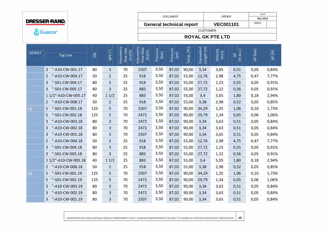
DOCUMENT ORDER DATE
Nov-2012
General technical report VEC001101 INDEX
CUSTOMER
ROYAL GK PTE LTD
CONSISTENTS WITH OUR CONTINUAL PRODUCT IMPROVEMENT POLICY, GUASCOR POWER RESERVES THE RIGHT TO CHANGE ANY SPECIFICATION WITHOUT PRIOR NOTICE. 68
GENSET Tag Line D
N
NP
S ("
)
Vo
lum
etri
c
flo
w r
ate
(m3
/h)
Vo
lum
etri
c
Flo
w R
ate
(ft3
/h)
Pre
ssu
re
(bar
)
Pre
ssu
re
(psi
)
Tem
p. (
ºC)
Equ
ival
ent
Len
gth
(m
)
Vel
oci
ty
(m/s
)
∆P
(m.w
.c.)
∆P
(b
ar)
∆P
(%
)
3 "-A10-CW-001.17 80 3 70 2507 3,50 87,02 90,00 3,34 3,65 0,51 0,05 0,84%
2 "-A10-CW-004.17 50 2 25 918 3,50 87,02 55,00 12,76 2,98 4,75 0,47 7,77%
3 "-S01-CW-004.17 80 3 25 918 3,50 87,02 55,00 27,72 1,23 0,55 0,05 0,91%
3 "-S01-CW-005.17 80 3 25 883 3,50 87,02 55,00 27,72 1,22 0,56 0,05 0,91%
1 1/2"-A10-CW-005.17 40 1 1/2 25 883 3,50 87,02 55,00 3,4 5,05 1,80 0,18 2,94%
2 "-A10-CW-008.17 50 2 25 918 3,50 87,02 55,00 3,38 2,98 0,52 0,05 0,85%
18 5 "-S01-CW-001.18 125 5 70 2507 3,50 87,02 90,00 34,29 1,35 1,06 0,10 1,73%
5 "-S01-CW-002.18 125 5 70 2472 3,50 87,02 90,00 29,79 1,34 0,65 0,06 1,06%
3 "-A10-CW-003.18 80 3 70 2472 3,50 87,02 90,00 3,34 3,63 0,51 0,05 0,84%
3 "-A10-CW-002.18 80 3 70 2472 3,50 87,02 90,00 3,34 3,63 0,51 0,05 0,84%
3 "-A10-CW-001.18 80 3 70 2507 3,50 87,02 90,00 3,34 3,65 0,51 0,05 0,84%
2 "-A10-CW-004.18 50 2 25 918 3,50 87,02 55,00 12,76 2,98 4,75 0,47 7,77%
3 "-S01-CW-004.18 80 3 25 918 3,50 87,02 55,00 27,72 1,23 0,55 0,05 0,91%
3 "-S01-CW-005.18 80 3 25 883 3,50 87,02 55,00 27,72 1,22 0,56 0,05 0,91%
1 1/2"-A10-CW-005.18 40 1 1/2 25 883 3,50 87,02 55,00 3,4 5,05 1,80 0,18 2,94%
2 "-A10-CW-008.18 50 2 25 918 3,50 87,02 55,00 3,38 2,98 0,52 0,05 0,85%
19 5 "-S01-CW-001.19 125 5 70 2507 3,50 87,02 90,00 34,29 1,35 1,06 0,10 1,73%
5 "-S01-CW-002.19 125 5 70 2472 3,50 87,02 90,00 29,79 1,34 0,65 0,06 1,06%
3 "-A10-CW-003.19 80 3 70 2472 3,50 87,02 90,00 3,34 3,63 0,51 0,05 0,84%
3 "-A10-CW-002.19 80 3 70 2472 3,50 87,02 90,00 3,34 3,63 0,51 0,05 0,84%
3 "-A10-CW-001.19 80 3 70 2507 3,50 87,02 90,00 3,34 3,65 0,51 0,05 0,84%

DOCUMENT ORDER DATE
Nov-2012
General technical report VEC001101 INDEX
CUSTOMER
ROYAL GK PTE LTD
CONSISTENTS WITH OUR CONTINUAL PRODUCT IMPROVEMENT POLICY, GUASCOR POWER RESERVES THE RIGHT TO CHANGE ANY SPECIFICATION WITHOUT PRIOR NOTICE. 69
GENSET Tag Line D
N
NP
S ("
)
Vo
lum
etri
c
flo
w r
ate
(m3
/h)
Vo
lum
etri
c
Flo
w R
ate
(ft3
/h)
Pre
ssu
re
(bar
)
Pre
ssu
re
(psi
)
Tem
p. (
ºC)
Equ
ival
ent
Len
gth
(m
)
Vel
oci
ty
(m/s
)
∆P
(m.w
.c.)
∆P
(b
ar)
∆P
(%
)
2 "-A10-CW-004.19 50 2 25 918 3,50 87,02 55,00 12,76 2,98 4,75 0,47 7,77%
3 "-S01-CW-004.19 80 3 25 918 3,50 87,02 55,00 27,72 1,23 0,55 0,05 0,91%
3 "-S01-CW-005.19 80 3 25 883 3,50 87,02 55,00 27,72 1,22 0,56 0,05 0,91%
1 1/2"-A10-CW-005.19 40 1 1/2 25 883 3,50 87,02 55,00 3,4 5,05 1,80 0,18 2,94%
2 "-A10-CW-008.19 50 2 25 918 3,50 87,02 55,00 3,38 2,98 0,52 0,05 0,85%
20 5 "-S01-CW-001.20 125 5 70 2507 3,50 87,02 90,00 34,29 1,35 1,06 0,10 1,73%
5 "-S01-CW-002.20 125 5 70 2472 3,50 87,02 90,00 29,79 1,34 0,65 0,06 1,06%
3 "-A10-CW-003.20 80 3 70 2472 3,50 87,02 90,00 3,34 3,63 0,51 0,05 0,84%
3 "-A10-CW-002.20 80 3 70 2472 3,50 87,02 90,00 3,34 3,63 0,51 0,05 0,84%
3 "-A10-CW-001.20 80 3 70 2507 3,50 87,02 90,00 3,34 3,65 0,51 0,05 0,84%
2 "-A10-CW-004.20 50 2 25 918 3,50 87,02 55,00 12,76 2,98 4,75 0,47 7,77%
3 "-S01-CW-004.20 80 3 25 918 3,50 87,02 55,00 27,72 1,23 0,55 0,05 0,91%
3 "-S01-CW-005.20 80 3 25 883 3,50 87,02 55,00 27,72 1,22 0,56 0,05 0,91%
1 1/2"-A10-CW-005.20 40 1 1/2 25 883 3,50 87,02 55,00 3,4 5,05 1,80 0,18 2,94%
2 "-A10-CW-008.20 50 2 25 918 3,50 87,02 55,00 3,38 2,98 0,52 0,05 0,85%
21 5 "-S01-CW-001.21 125 5 70 2507 3,50 87,02 90,00 34,29 1,35 1,06 0,10 1,73%
5 "-S01-CW-002.21 125 5 70 2472 3,50 87,02 90,00 29,79 1,34 0,65 0,06 1,06%
3 "-A10-CW-003.21 80 3 70 2472 3,50 87,02 90,00 3,34 3,63 0,51 0,05 0,84%
3 "-A10-CW-002.21 80 3 70 2472 3,50 87,02 90,00 3,34 3,63 0,51 0,05 0,84%
3 "-A10-CW-001.21 80 3 70 2507 3,50 87,02 90,00 3,34 3,65 0,51 0,05 0,84%
2 "-A10-CW-004.21 50 2 25 918 3,50 87,02 55,00 12,76 2,98 4,75 0,47 7,77%

DOCUMENT ORDER DATE
Nov-2012
General technical report VEC001101 INDEX
CUSTOMER
ROYAL GK PTE LTD
CONSISTENTS WITH OUR CONTINUAL PRODUCT IMPROVEMENT POLICY, GUASCOR POWER RESERVES THE RIGHT TO CHANGE ANY SPECIFICATION WITHOUT PRIOR NOTICE. 70
GENSET Tag Line D
N
NP
S ("
)
Vo
lum
etri
c
flo
w r
ate
(m3
/h)
Vo
lum
etri
c
Flo
w R
ate
(ft3
/h)
Pre
ssu
re
(bar
)
Pre
ssu
re
(psi
)
Tem
p. (
ºC)
Equ
ival
ent
Len
gth
(m
)
Vel
oci
ty
(m/s
)
∆P
(m.w
.c.)
∆P
(b
ar)
∆P
(%
)
3 "-S01-CW-004.21 80 3 25 918 3,50 87,02 55,00 27,72 1,23 0,55 0,05 0,91%
3 "-S01-CW-005.21 80 3 25 883 3,50 87,02 55,00 27,72 1,22 0,56 0,05 0,91%
1 1/2"-A10-CW-005.21 40 1 1/2 25 883 3,50 87,02 55,00 3,4 5,05 1,80 0,18 2,94%
2 "-A10-CW-008.21 50 2 25 918 3,50 87,02 55,00 3,38 2,98 0,52 0,05 0,85%
22 5 "-S01-CW-001.22 125 5 70 2507 3,50 87,02 90,00 34,29 1,35 1,06 0,10 1,73%
5 "-S01-CW-002.22 125 5 70 2472 3,50 87,02 90,00 29,79 1,34 0,65 0,06 1,06%
3 "-A10-CW-003.22 80 3 70 2472 3,50 87,02 90,00 3,34 3,63 0,51 0,05 0,84%
3 "-A10-CW-002.22 80 3 70 2472 3,50 87,02 90,00 3,34 3,63 0,51 0,05 0,84%
3 "-A10-CW-001.22 80 3 70 2507 3,50 87,02 90,00 3,34 3,65 0,51 0,05 0,84%
2 "-A10-CW-004.22 50 2 25 918 3,50 87,02 55,00 12,76 2,98 4,75 0,47 7,77%
3 "-S01-CW-004.22 80 3 25 918 3,50 87,02 55,00 27,72 1,23 0,55 0,05 0,91%
3 "-S01-CW-005.22 80 3 25 883 3,50 87,02 55,00 27,72 1,22 0,56 0,05 0,91%
1 1/2"-A10-CW-005.22 40 1 1/2 25 883 3,50 87,02 55,00 3,4 5,05 1,80 0,18 2,94%
2 "-A10-CW-008.22 50 2 25 918 3,50 87,02 55,00 3,38 2,98 0,52 0,05 0,85%
23 5 "-S01-CW-001.23 125 5 70 2507 3,50 87,02 90,00 34,29 1,35 1,06 0,10 1,73%
5 "-S01-CW-002.23 125 5 70 2472 3,50 87,02 90,00 29,79 1,34 0,65 0,06 1,06%
3 "-A10-CW-003.23 80 3 70 2472 3,50 87,02 90,00 3,34 3,63 0,51 0,05 0,84%
3 "-A10-CW-002.23 80 3 70 2472 3,50 87,02 90,00 3,34 3,63 0,51 0,05 0,84%
3 "-A10-CW-001.23 80 3 70 2507 3,50 87,02 90,00 3,34 3,65 0,51 0,05 0,84%
2 "-A10-CW-004.23 50 2 25 918 3,50 87,02 55,00 12,76 2,98 4,75 0,47 7,77%
3 "-S01-CW-004.23 80 3 25 918 3,50 87,02 55,00 27,72 1,23 0,55 0,05 0,91%

DOCUMENT ORDER DATE
Nov-2012
General technical report VEC001101 INDEX
CUSTOMER
ROYAL GK PTE LTD
CONSISTENTS WITH OUR CONTINUAL PRODUCT IMPROVEMENT POLICY, GUASCOR POWER RESERVES THE RIGHT TO CHANGE ANY SPECIFICATION WITHOUT PRIOR NOTICE. 71
GENSET Tag Line D
N
NP
S ("
)
Vo
lum
etri
c
flo
w r
ate
(m3
/h)
Vo
lum
etri
c
Flo
w R
ate
(ft3
/h)
Pre
ssu
re
(bar
)
Pre
ssu
re
(psi
)
Tem
p. (
ºC)
Equ
ival
ent
Len
gth
(m
)
Vel
oci
ty
(m/s
)
∆P
(m.w
.c.)
∆P
(b
ar)
∆P
(%
)
3 "-S01-CW-005.23 80 3 25 883 3,50 87,02 55,00 27,72 1,22 0,56 0,05 0,91%
1 1/2"-A10-CW-005.23 40 1 1/2 25 883 3,50 87,02 55,00 3,4 5,05 1,80 0,18 2,94%
2 "-A10-CW-008.23 50 2 25 918 3,50 87,02 55,00 3,38 2,98 0,52 0,05 0,85%
24 5 "-S01-CW-001.24 125 5 70 2507 3,50 87,02 90,00 34,29 1,35 1,06 0,10 1,73%
5 "-S01-CW-002.24 125 5 70 2472 3,50 87,02 90,00 29,79 1,34 0,65 0,06 1,06%
3 "-A10-CW-003.24 80 3 70 2472 3,50 87,02 90,00 3,34 3,63 0,51 0,05 0,84%
3 "-A10-CW-002.24 80 3 70 2472 3,50 87,02 90,00 3,34 3,63 0,51 0,05 0,84%
3 "-A10-CW-001.24 80 3 70 2507 3,50 87,02 90,00 3,34 3,65 0,51 0,05 0,84%
2 "-A10-CW-004.24 50 2 25 918 3,50 87,02 55,00 12,76 2,98 4,75 0,47 7,77%
3 "-S01-CW-004.24 80 3 25 918 3,50 87,02 55,00 27,72 1,23 0,55 0,05 0,91%
3 "-S01-CW-005.24 80 3 25 883 3,50 87,02 55,00 27,72 1,22 0,56 0,05 0,91%
1 1/2"-A10-CW-005.24 40 1 1/2 25 883 3,50 87,02 55,00 3,4 5,05 1,80 0,18 2,94%
2 "-A10-CW-008.24 50 2 25 918 3,50 87,02 55,00 3,38 2,98 0,52 0,05 0,85%
25 5 "-S01-CW-001.25 125 5 70 2507 3,50 87,02 90,00 34,29 1,35 1,06 0,10 1,73%
5 "-S01-CW-002.25 125 5 70 2472 3,50 87,02 90,00 29,79 1,34 0,65 0,06 1,06%
3 "-A10-CW-003.25 80 3 70 2472 3,50 87,02 90,00 3,34 3,63 0,51 0,05 0,84%
3 "-A10-CW-002.25 80 3 70 2472 3,50 87,02 90,00 3,34 3,63 0,51 0,05 0,84%
3 "-A10-CW-001.25 80 3 70 2507 3,50 87,02 90,00 3,34 3,65 0,51 0,05 0,84%
2 "-A10-CW-004.25 50 2 25 918 3,50 87,02 55,00 12,76 2,98 4,75 0,47 7,77%
3 "-S01-CW-004.25 80 3 25 918 3,50 87,02 55,00 27,72 1,23 0,55 0,05 0,91%
3 "-S01-CW-005.25 80 3 25 883 3,50 87,02 55,00 27,72 1,22 0,56 0,05 0,91%
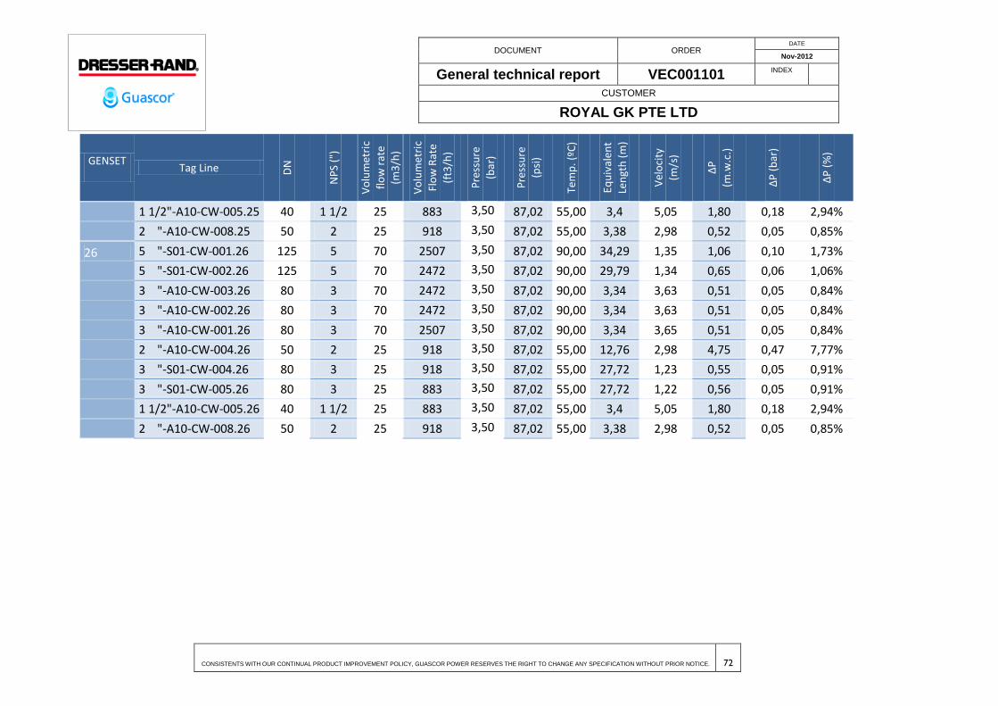
DOCUMENT ORDER DATE
Nov-2012
General technical report VEC001101 INDEX
CUSTOMER
ROYAL GK PTE LTD
CONSISTENTS WITH OUR CONTINUAL PRODUCT IMPROVEMENT POLICY, GUASCOR POWER RESERVES THE RIGHT TO CHANGE ANY SPECIFICATION WITHOUT PRIOR NOTICE. 72
GENSET Tag Line D
N
NP
S ("
)
Vo
lum
etri
c
flo
w r
ate
(m3
/h)
Vo
lum
etri
c
Flo
w R
ate
(ft3
/h)
Pre
ssu
re
(bar
)
Pre
ssu
re
(psi
)
Tem
p. (
ºC)
Equ
ival
ent
Len
gth
(m
)
Vel
oci
ty
(m/s
)
∆P
(m.w
.c.)
∆P
(b
ar)
∆P
(%
)
1 1/2"-A10-CW-005.25 40 1 1/2 25 883 3,50 87,02 55,00 3,4 5,05 1,80 0,18 2,94%
2 "-A10-CW-008.25 50 2 25 918 3,50 87,02 55,00 3,38 2,98 0,52 0,05 0,85%
26 5 "-S01-CW-001.26 125 5 70 2507 3,50 87,02 90,00 34,29 1,35 1,06 0,10 1,73%
5 "-S01-CW-002.26 125 5 70 2472 3,50 87,02 90,00 29,79 1,34 0,65 0,06 1,06%
3 "-A10-CW-003.26 80 3 70 2472 3,50 87,02 90,00 3,34 3,63 0,51 0,05 0,84%
3 "-A10-CW-002.26 80 3 70 2472 3,50 87,02 90,00 3,34 3,63 0,51 0,05 0,84%
3 "-A10-CW-001.26 80 3 70 2507 3,50 87,02 90,00 3,34 3,65 0,51 0,05 0,84%
2 "-A10-CW-004.26 50 2 25 918 3,50 87,02 55,00 12,76 2,98 4,75 0,47 7,77%
3 "-S01-CW-004.26 80 3 25 918 3,50 87,02 55,00 27,72 1,23 0,55 0,05 0,91%
3 "-S01-CW-005.26 80 3 25 883 3,50 87,02 55,00 27,72 1,22 0,56 0,05 0,91%
1 1/2"-A10-CW-005.26 40 1 1/2 25 883 3,50 87,02 55,00 3,4 5,05 1,80 0,18 2,94%
2 "-A10-CW-008.26 50 2 25 918 3,50 87,02 55,00 3,38 2,98 0,52 0,05 0,85%

DOCUMENT ORDER DATE
Nov-2012
General technical report VEC001101 INDEX
CUSTOMER
ROYAL GK PTE LTD
CONSISTENTS WITH OUR CONTINUAL PRODUCT IMPROVEMENT POLICY, GUASCOR POWER RESERVES THE RIGHT TO CHANGE ANY SPECIFICATION WITHOUT PRIOR NOTICE. 73
8 ENGINE LUBE OIL SYSTEM
The function of this system is to ensure oil is available in all the lubricating circuits of the
engine, so that oil pressure quickly builds up a sufficient level for correct operations in
those applications where the engine is expected to develop its full power after the start
command.
For this application a single prelubrication process of 10 minutes is recommended prior
to any cold start operation. This operation is done with an electrical pump which is
supplied installed in an external oil tank of 300L. It’s a 24Vdc pump, thus it will be feed
from genset batteries allowing a start in a blackout condition of the plant. Once the
genset is started the mechanical oil pump of the genset will build up the oil pressure of
the engine.
Lube oil system includes four lines for connection of the engine and Lubricant oil tank.
The engine has three openings to connect the lubrication:
1. Filling
2. Pre-lubrication
3. Emptying
Connections are implemented under polyethylene ¾” pipes.
System includes a multifunctional pump with a set of valves defining the function to
perform. In normal operation the valves will allow the prelube operation, but the pump
may be used also to fill the engine with oil or empty it, being useful for the oil change
operations.
Technical instructions will be provided in further information for operation of this system.
The oil recommended for the lubrication is the Guascor Motoroil 3040 Plus Lube Oil for
Natural Gas-Fuelled and Ethanol engines.
Design of the oil prelube system is described in the following drawings:
12-01: General Flow Diagram.

DOCUMENT ORDER DATE
Nov-2012
General technical report VEC001101 INDEX
CUSTOMER
ROYAL GK PTE LTD
CONSISTENTS WITH OUR CONTINUAL PRODUCT IMPROVEMENT POLICY, GUASCOR POWER RESERVES THE RIGHT TO CHANGE ANY SPECIFICATION WITHOUT PRIOR NOTICE. 74
13-02: Lube Oil P&I diagram.
62-04: Lay out of pipes Lube Oil Typical Detail
Genset installation manual includes also information about the oil tank, automatic
engine oil level controller and oil level indicator.
Table 7.Lube oil specification.
PIPE MATERIAL
SPECIFICATIONS
SPECIFICATIONS
Nº PE2 Rev. 00
SERVICE: Lube oil (LO)
NOMINAL PRESSURE: PIPING MATERIAL:
Multilayered Plastic
polymer/aluminium
(Al)/crosslinked
polyethylene pipes
(PE-X) CORROSION PERMISSIBLE:
SERVICE LIMITS FROM: 20 bar; 20º C TO: 10 bar; +95ºC
ITEM SIZE ENDS DESCRIPTION
FROM TO
PIPE 20x1,9mm PE Multilayered Plastic polymer/aluminium
(Al)/crosslinked polyethylene pipes (PE-X) UNE-EN
ISO 21003
FITTINGS 20x1,9mm
Copper; press fitting or Sliding sleeve Galadiator
system.
8.1 BLOWBY GASES EXHAUSTING SYSTEM
In parallel to oil prelube system it should be also be taking in consideration the blowby
gases exhausting system, also known as crankcase breathing.
The “blowby gases” are the portion of fire gases that enter the engine oil casing through
the combustion chamber sealing segments. These gases increase the pressure of the
crankcase casing over the atmospheric pressure and thus should be removed. They have
to be also conducted outside the engine room to avoid risks of explosion or fire, the
clogging of the filters or the creation of a polluted environment. The document of the
genset installation manual IT-C-A-25-001e makes a description of this installation.
These drawings show the design of this blowby exhausting circuit.
13-02: Lube Oil P&I diagram.
61-02 to 61-05: Lay out of pipes (blowby gases circuit in blue colour)
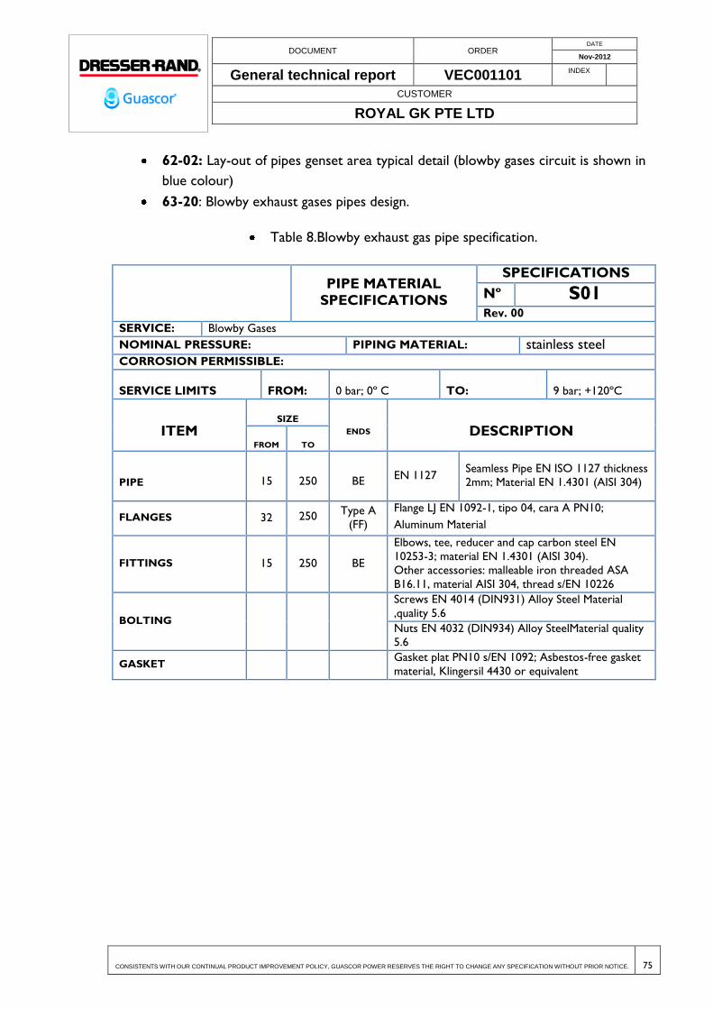
DOCUMENT ORDER DATE
Nov-2012
General technical report VEC001101 INDEX
CUSTOMER
ROYAL GK PTE LTD
CONSISTENTS WITH OUR CONTINUAL PRODUCT IMPROVEMENT POLICY, GUASCOR POWER RESERVES THE RIGHT TO CHANGE ANY SPECIFICATION WITHOUT PRIOR NOTICE. 75
62-02: Lay-out of pipes genset area typical detail (blowby gases circuit is shown in
blue colour)
63-20: Blowby exhaust gases pipes design.
Table 8.Blowby exhaust gas pipe specification.
PIPE MATERIAL
SPECIFICATIONS
SPECIFICATIONS
Nº S01 Rev. 00
SERVICE: Blowby Gases
NOMINAL PRESSURE: PIPING MATERIAL: stainless steel CORROSION PERMISSIBLE:
SERVICE LIMITS FROM: 0 bar; 0º C TO: 9 bar; +120ºC
ITEM SIZE
ENDS DESCRIPTION FROM TO
PIPE 15 250 BE EN 1127
Seamless Pipe EN ISO 1127 thickness
2mm; Material EN 1.4301 (AISI 304)
FLANGES 32 250 Type A
(FF)
Flange LJ EN 1092-1, tipo 04, cara A PN10;
Aluminum Material
FITTINGS 15 250 BE
Elbows, tee, reducer and cap carbon steel EN
10253-3; material EN 1.4301 (AISI 304).
Other accessories: malleable iron threaded ASA
B16.11, material AISI 304, thread s/EN 10226
BOLTING
Screws EN 4014 (DIN931) Alloy Steel Material
,quality 5.6
Nuts EN 4032 (DIN934) Alloy SteelMaterial quality
5.6
GASKET Gasket plat PN10 s/EN 1092; Asbestos-free gasket
material, Klingersil 4430 or equivalent
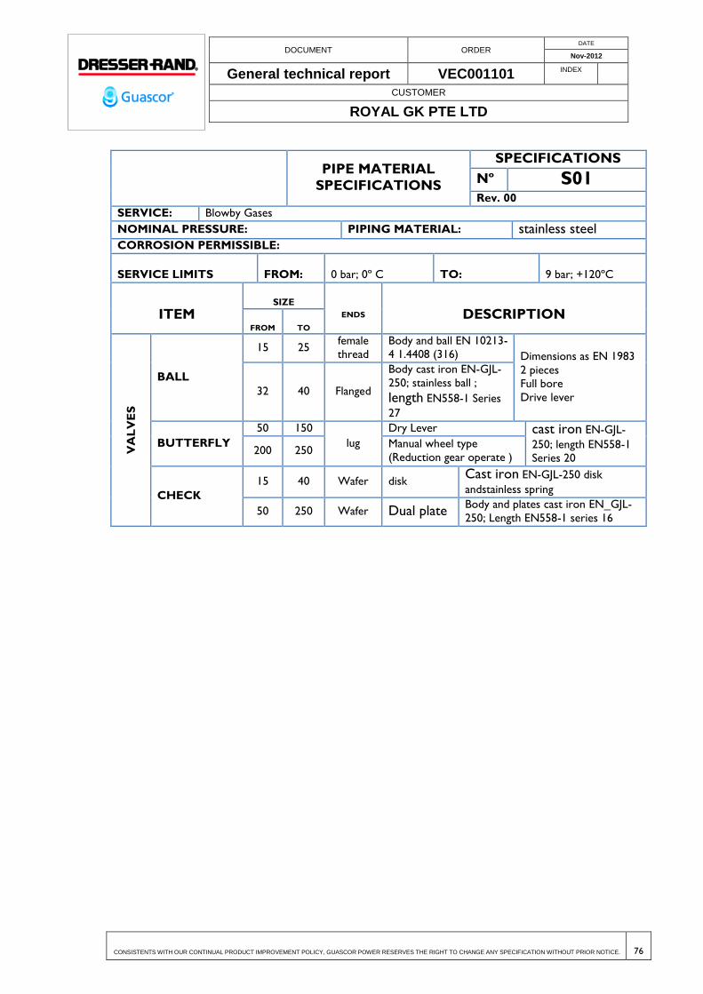
DOCUMENT ORDER DATE
Nov-2012
General technical report VEC001101 INDEX
CUSTOMER
ROYAL GK PTE LTD
CONSISTENTS WITH OUR CONTINUAL PRODUCT IMPROVEMENT POLICY, GUASCOR POWER RESERVES THE RIGHT TO CHANGE ANY SPECIFICATION WITHOUT PRIOR NOTICE. 76
PIPE MATERIAL
SPECIFICATIONS
SPECIFICATIONS
Nº S01 Rev. 00
SERVICE: Blowby Gases
NOMINAL PRESSURE: PIPING MATERIAL: stainless steel CORROSION PERMISSIBLE:
SERVICE LIMITS FROM: 0 bar; 0º C TO: 9 bar; +120ºC
ITEM SIZE
ENDS DESCRIPTION FROM TO
VA
LV
ES
BALL
15 25 female
thread Body and ball EN 10213-
4 1.4408 (316) Dimensions as EN 1983
2 pieces
Full bore
Drive lever 32 40 Flanged
Body cast iron EN-GJL-
250; stainless ball ;
length EN558-1 Series
27
BUTTERFLY
50 150
lug Dry Lever cast iron EN-GJL-
250; length EN558-1
Series 20 200 250
Manual wheel type
(Reduction gear operate )
CHECK
15 40 Wafer disk Cast iron EN-GJL-250 disk
andstainless spring
50 250 Wafer Dual plate Body and plates cast iron EN_GJL-
250; Length EN558-1 series 16

DOCUMENT ORDER DATE
Nov-2012
General technical report VEC001101 INDEX
CUSTOMER
ROYAL GK PTE LTD
CONSISTENTS WITH OUR CONTINUAL PRODUCT IMPROVEMENT POLICY, GUASCOR POWER RESERVES THE RIGHT TO CHANGE ANY SPECIFICATION WITHOUT PRIOR NOTICE. 77
9 ENGINE VENTILATION SYSTEM
9.1 DESCRIPTION OF THE ENGINE ROOM VENTILATION
The ventilation of the engine room should satisfy two fundamental functions:
Guarantee the environmental conditions, which permit the optimum performance
level of the engine and equipment.
Provide the most comfortable environmental conditions possible for the people
who have to work in the engine room.
In designing a ventilation system, the same importance should be given to the necessary
volume of air as to the flow direction.
The ventilation system must be able to provide sufficient combustion air and to remove
radiation heat from the rest of the facility.
Generally, the air flow direction in an engine room will match the following pattern
The entry of air in the engine room should be from the area furthest away from
any sources of heat.
The fresh air should be able to flow freely from the point of entry to the sources
of heat, in its circulation towards the point of exit.
The expulsion of hot air should be at a point directly above the most important
sources of heat, avoiding the intake of the exhaust gas.
Where the temperature of the engine room or, in particular, of the crankcase
gases return lines to the intake manifold is too low, the said lines must be heat-
insulated so as to prevent condensation in the said piping section.
In all cases, the hot air should be forced out of the engine room by means of an outlet
duct, without allowing it to mix with the fresh ventilation air.
The detailed information of the lay out and the ventilation system assembly is available in
the Annex (Ventilation System. Assembly Manual).

DOCUMENT ORDER DATE
Nov-2012
General technical report VEC001101 INDEX
CUSTOMER
ROYAL GK PTE LTD
CONSISTENTS WITH OUR CONTINUAL PRODUCT IMPROVEMENT POLICY, GUASCOR POWER RESERVES THE RIGHT TO CHANGE ANY SPECIFICATION WITHOUT PRIOR NOTICE. 78
9.2 VENTILATION SYSTEM
9.2.1 Forced ventilation (pusher fan)
We recommend this ventilation system for all machine rooms in general. Both air inlet
and outlet depend on the location of the air intake filters and alternator, as the following
picture shows:
ALTERNATOR
SIDE

DOCUMENT ORDER DATE
Nov-2012
General technical report VEC001101 INDEX
CUSTOMER
ROYAL GK PTE LTD
CONSISTENTS WITH OUR CONTINUAL PRODUCT IMPROVEMENT POLICY, GUASCOR POWER RESERVES THE RIGHT TO CHANGE ANY SPECIFICATION WITHOUT PRIOR NOTICE. 79
The air flow through each engine is guaranteed for a motor-fan located above
every single engine.
These fans will be flowing fresh air when the engine is running.
There is a circular duct mounted to the motor-fan in order to improve the fresh
air direction blowing through the Gensets.
9.2.2 Ventilation module feature
The Air input module will contain the following elements:
Plenum Dimensions ....................................................... 1,600x1,400x1,847 mm
Motor Driven Fan Model ................................................... S&P TGT 4/800 6/18
Flow Rate .............................................................................................. 25,000 m3/h
Airflow speed ............................................................................................... 13.7 m/s
Available Static Pressure .............................................................................. 150 Pa
Nominal Input ................................................................................................... 3 kW
Speed of Rotation .................................................................................... 1400 rpm
Voltage & Frequency ................................................................... 3P 400 V 50 HZ
Nominal Current .............................................................................................. 6.5 A
Degree of Protection ........................................................................................ IP55
Electrical insulation class ........................................................................................ F
Refer to the general drawing (35-02) for further information.
DOCUMENT ORDER DATE
Nov-2012
General technical report VEC001101 INDEX
CUSTOMER
ROYAL GK PTE LTD
CONSISTENTS WITH OUR CONTINUAL PRODUCT IMPROVEMENT POLICY, GUASCOR POWER RESERVES THE RIGHT TO CHANGE ANY SPECIFICATION WITHOUT PRIOR NOTICE. 80
10 NATURAL GAS FUEL SUPPLY
10.1 GENERAL DESCRIPTION
The Natural Gas is distributed inside the power plant through a pipelines network.
In the regulation and metering station (R.M.S.), the natural gas is filtered and adjusted to
appropriate pressure level, in order to provide at the engines the power needed for
electrical generation.
The R.M.S. is provided with a non continuous gas analyzer whose function is to monitor
CH4, O2 and CO2 content in natural gas, and the communications output will be through
digital modbus and 4-20 mA signal.
Also, 2 electrovalves will be installed at R.M.S. outlet, which will be actuated in case of
serious alarm caused by loss of gas quality, gas leakage or fire. This electrovalves will be
supplied by 24Vdc batteries set located at the R.M.S. control panel to allow their control
also in situations of black-out or power supply shortages.
After the R.M.S., natural gas is sent into the two power generation engine rooms through
pipe internal network. Every engine is fed from a manifold located outside the engine
room,it means that there is one pipe entering the building for each engine.
Head losses in pipes are allowed while the pressure level at the inlet of the feeding ramps
is adequate in order to ensure proper running of the engine.
These drawings show the design of the Natural Gas Fuel Supply circuits
12-01: General Flow Diagram.
13-03: Natural Gas P&I diagram.
61-01: Lay-out of pipes area GRMS
61-02 to 61-05: Lay out of pipes (natural gas circuit in red colour)
62-02: Lay-out of pipes genset area typical detail (natural gas circuit is shown in
red colour)
62-03: Section Pipes area GRMS
63-16 to 63-18: Natural gas pipes design.
65-01: General connection.
DOCUMENT ORDER DATE
Nov-2012
General technical report VEC001101 INDEX
CUSTOMER
ROYAL GK PTE LTD
CONSISTENTS WITH OUR CONTINUAL PRODUCT IMPROVEMENT POLICY, GUASCOR POWER RESERVES THE RIGHT TO CHANGE ANY SPECIFICATION WITHOUT PRIOR NOTICE. 81
10.1.1 Internal connection.
The Service Pipes includes the whole of pipelines and fittings between the Service Key
(main supply valve), excluding this, and the Buildings Key (shut off valves at the entrance
of engine rooms facility), including these, in case of gas receiver installations supplied from
distribution pipe network.
10.1.2 Service pipes
10.1.2.1 General features
The Service Pipes of Natural Gas involves the different gas pipes with its fittings and
auxiliary items between the Regulating and Metering Station (R.M.S.) and the gas train of
every engine.
The R.M.S. is located in the south side of the Power Plant. It has two pipe outlets to
provide natural gas, one for each engine room.
TheService Pipes is formed by the following stretches:
1) R.M.S. output:Stretch comprised between R.M.S. and the engine rooms
area. Both pipes run parallel each other and in a buried stretch for crossing
the road. Once the road is crossed, the pipes get out to the surface and runs
through an aerial stretch, above a lintel, up to the engine rooms.
2) Engine rooms: The pipes are separated, each one toward their own engine
room with a symmetric route. The pipes goes down to the ground at the
entrance of the engine rooms, where there are shut off valves (building keys)
to lock the gas supply.The pipe distribution in the engine rooms is through
an aerial stretch, 3 m above the ground and supported in metallic structures
fixed in the pillars of the building.
3) Gas supply to engines:Stretch between the pipe distribution and the gas
train of the engines. At the inlet of the gas train, there are a shut off valve to
isolate the engine from the gas supply.

DOCUMENT ORDER DATE
Nov-2012
General technical report VEC001101 INDEX
CUSTOMER
ROYAL GK PTE LTD
CONSISTENTS WITH OUR CONTINUAL PRODUCT IMPROVEMENT POLICY, GUASCOR POWER RESERVES THE RIGHT TO CHANGE ANY SPECIFICATION WITHOUT PRIOR NOTICE. 82
10.1.2.2 Calculations
10.1.2.2.1 INSIDE DIAMETER CALCULATION
The output pressure from the R.M.S. will be 3 bar g, and it will be the design pressure for
the gas distribution pipelines of the power plant.
The external gas service arrives at the power plant with a range between 10 and 40 bar g
so the design pressure will be 10 bar g because is the pressure that produces higher
velocities.
The procedure to calculate the inside diameter of the pipe is to establish an initial
diameter and apply the formula to determine the flow velocity and head loss to ensure
that the obtained values are according to the current Standards.
10.1.2.2.1.1 DESIGN ASSUMPTION
The design foundations are the following:
R.M.S. pressure output (bar g) ........................................................... 3
Max. Volumetric flow rate (Nm3/h):
Pipe distribution Engine Room 1 ........................................ 6.250,00
Pipe distribution Engine Room 2 ........................................ 6.250,00
Gas supply to engines (1-26) ........................................................ 481
Max. Design Velocity (m/s) ............................................................... 20
10.1.2.2.1.2 HEAD LOSS
The procedure to calculate the head loss in each stretch of the installation is through
applying the RENOUARD formula:
-4,821,822
B
2
A DQLS5,51PP
The parameters descriptions are as follow:
PA: Absolute pressure at the beginning of the stretch.
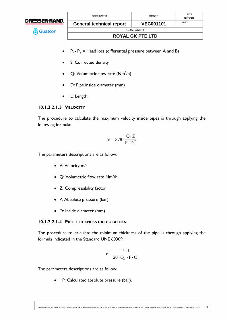
DOCUMENT ORDER DATE
Nov-2012
General technical report VEC001101 INDEX
CUSTOMER
ROYAL GK PTE LTD
CONSISTENTS WITH OUR CONTINUAL PRODUCT IMPROVEMENT POLICY, GUASCOR POWER RESERVES THE RIGHT TO CHANGE ANY SPECIFICATION WITHOUT PRIOR NOTICE. 83
PA- PB = Head loss (differential pressure between A and B)
S: Corrected density
Q: Volumetric flow rate (Nm3/h)
D: Pipe inside diameter (mm)
L: Length.
10.1.2.2.1.3 VELOCITY
The procedure to calculate the maximum velocity inside pipes is through applying the
following formula:
V = 378Q Z
P D 2
The parameters descriptions are as follow:
V: Velocity m/s
Q: Volumetric flow rate Nm3/h
Z: Compressibility factor
P: Absolute pressure (bar)
D: Inside diameter (mm)
10.1.2.2.1.4 PIPE THICKNESS CALCULATION
The procedure to calculate the minimum thickness of the pipe is through applying the
formula indicated in the Standard UNE 60309:
CFQ20
dP=e
e
The parameters descriptions are as follow:
P: Calculated absolute pressure (bar).
DOCUMENT ORDER DATE
Nov-2012
General technical report VEC001101 INDEX
CUSTOMER
ROYAL GK PTE LTD
CONSISTENTS WITH OUR CONTINUAL PRODUCT IMPROVEMENT POLICY, GUASCOR POWER RESERVES THE RIGHT TO CHANGE ANY SPECIFICATION WITHOUT PRIOR NOTICE. 84
Qe: Yield strength of the pipe material (N/mm2).
e: Theoretical thickness of the pipe (mm).
d: Outside diameter of the pipe (mm).
F: Coefficient for calculations. Indicated in the Standard UNE 60305 = 0,4
C: Welding efficiency = 1
1) The minimum thickness of poliethylene pipes (HDPE) for gas are according to the
current standards so it is allowed to use in the specificated pressure range in the plant.
10.1.2.2.1.5 MEASUREMENT TABLE
The calculation results are shown in the following table.
As the table shows, the velocity values obtained in the calculations are under the
maximum velocity allowed by Standards for each stretch, 20 m/safter the R.M.S, and the
thickness of the selected pipes are above the minimum allowable thickness required by
the Standard.
The R.M.S. will adjust the pressure to 3 bar g, and thus this will be the nominal pressure
used for all gas pipelines installed in the plant.
The pipelines with tag “OTHER1, 2 or 3” correspond to the power plant main
connection of natural gas, before the R.M.S. For those pipelines the maximum velocity
allowed by the Standard is 30 m/s.
Gas supply at natural gas take-off will have a pressure between 10 and 40 bar g, and thus
design pressure for these pipelines will be 10 bar g as this is the pressure at which the
maximum flow rates are produced.
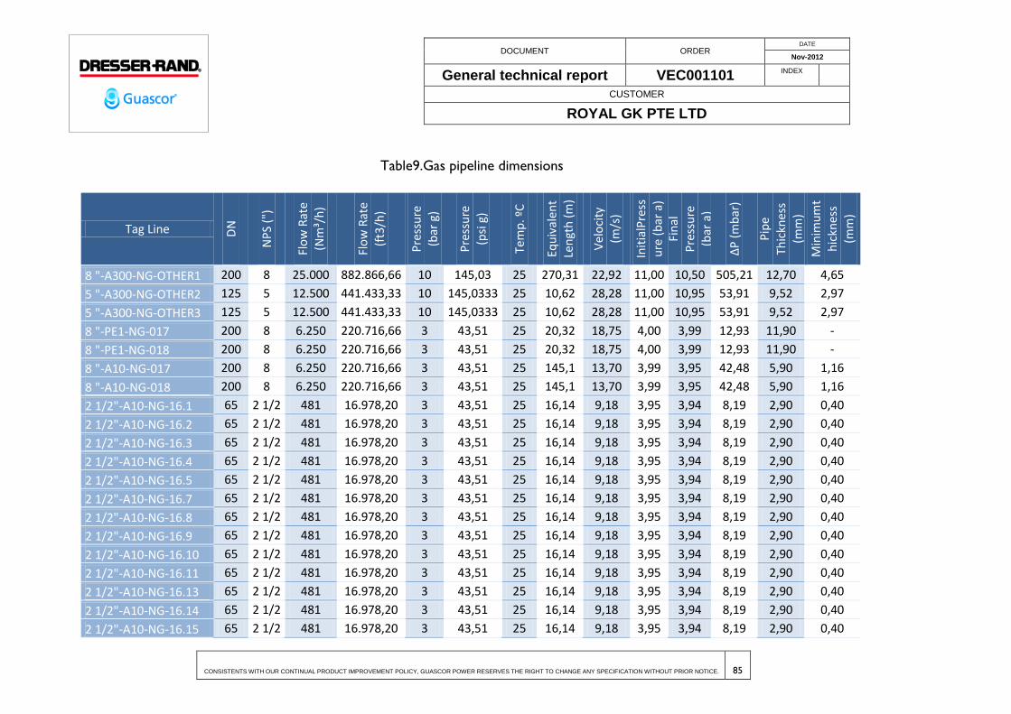
DOCUMENT ORDER DATE
Nov-2012
General technical report VEC001101 INDEX
CUSTOMER
ROYAL GK PTE LTD
CONSISTENTS WITH OUR CONTINUAL PRODUCT IMPROVEMENT POLICY, GUASCOR POWER RESERVES THE RIGHT TO CHANGE ANY SPECIFICATION WITHOUT PRIOR NOTICE. 85
Table9.Gas pipeline dimensions
Tag Line DN
NP
S ("
)
Flo
w R
ate
(Nm
³/h
)
Flo
w R
ate
(ft3
/h)
Pre
ssu
re
(bar
g)
Pre
ssu
re
(psi
g)
Tem
p. º
C
Equ
ival
ent
Len
gth
(m
)
Vel
oci
ty
(m/s
)
Init
ialP
ress
ure
(b
ar a
) Fi
nal
P
ress
ure
(b
ar a
)
∆P
(m
bar
)
Pip
e Th
ickn
ess
(mm
)
Min
imu
mt
hic
knes
s
(mm
)
8 "-A300-NG-OTHER1 200 8 25.000 882.866,66 10 145,03 25 270,31 22,92 11,00 10,50 505,21 12,70 4,65
5 "-A300-NG-OTHER2 125 5 12.500 441.433,33 10 145,0333 25 10,62 28,28 11,00 10,95 53,91 9,52 2,97
5 "-A300-NG-OTHER3 125 5 12.500 441.433,33 10 145,0333 25 10,62 28,28 11,00 10,95 53,91 9,52 2,97
8 "-PE1-NG-017 200 8 6.250 220.716,66 3 43,51 25 20,32 18,75 4,00 3,99 12,93 11,90 -
8 "-PE1-NG-018 200 8 6.250 220.716,66 3 43,51 25 20,32 18,75 4,00 3,99 12,93 11,90 -
8 "-A10-NG-017 200 8 6.250 220.716,66 3 43,51 25 145,1 13,70 3,99 3,95 42,48 5,90 1,16
8 "-A10-NG-018 200 8 6.250 220.716,66 3 43,51 25 145,1 13,70 3,99 3,95 42,48 5,90 1,16
2 1/2"-A10-NG-16.1 65 2 1/2 481 16.978,20 3 43,51 25 16,14 9,18 3,95 3,94 8,19 2,90 0,40
2 1/2"-A10-NG-16.2 65 2 1/2 481 16.978,20 3 43,51 25 16,14 9,18 3,95 3,94 8,19 2,90 0,40
2 1/2"-A10-NG-16.3 65 2 1/2 481 16.978,20 3 43,51 25 16,14 9,18 3,95 3,94 8,19 2,90 0,40
2 1/2"-A10-NG-16.4 65 2 1/2 481 16.978,20 3 43,51 25 16,14 9,18 3,95 3,94 8,19 2,90 0,40
2 1/2"-A10-NG-16.5 65 2 1/2 481 16.978,20 3 43,51 25 16,14 9,18 3,95 3,94 8,19 2,90 0,40
2 1/2"-A10-NG-16.7 65 2 1/2 481 16.978,20 3 43,51 25 16,14 9,18 3,95 3,94 8,19 2,90 0,40
2 1/2"-A10-NG-16.8 65 2 1/2 481 16.978,20 3 43,51 25 16,14 9,18 3,95 3,94 8,19 2,90 0,40
2 1/2"-A10-NG-16.9 65 2 1/2 481 16.978,20 3 43,51 25 16,14 9,18 3,95 3,94 8,19 2,90 0,40
2 1/2"-A10-NG-16.10 65 2 1/2 481 16.978,20 3 43,51 25 16,14 9,18 3,95 3,94 8,19 2,90 0,40
2 1/2"-A10-NG-16.11 65 2 1/2 481 16.978,20 3 43,51 25 16,14 9,18 3,95 3,94 8,19 2,90 0,40
2 1/2"-A10-NG-16.13 65 2 1/2 481 16.978,20 3 43,51 25 16,14 9,18 3,95 3,94 8,19 2,90 0,40
2 1/2"-A10-NG-16.14 65 2 1/2 481 16.978,20 3 43,51 25 16,14 9,18 3,95 3,94 8,19 2,90 0,40
2 1/2"-A10-NG-16.15 65 2 1/2 481 16.978,20 3 43,51 25 16,14 9,18 3,95 3,94 8,19 2,90 0,40
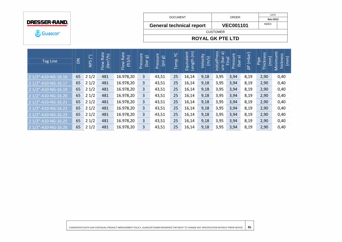
DOCUMENT ORDER DATE
Nov-2012
General technical report VEC001101 INDEX
CUSTOMER
ROYAL GK PTE LTD
CONSISTENTS WITH OUR CONTINUAL PRODUCT IMPROVEMENT POLICY, GUASCOR POWER RESERVES THE RIGHT TO CHANGE ANY SPECIFICATION WITHOUT PRIOR NOTICE. 86
Tag Line DN
NP
S ("
)
Flo
w R
ate
(Nm
³/h
)
Flo
w R
ate
(ft3
/h)
Pre
ssu
re
(bar
g)
Pre
ssu
re
(psi
g)
Tem
p. º
C
Equ
ival
ent
Len
gth
(m
)
Vel
oci
ty
(m/s
)
Init
ialP
ress
ure
(b
ar a
) Fi
nal
P
ress
ure
(b
ar a
)
∆P
(m
bar
)
Pip
e Th
ickn
ess
(mm
)
Min
imu
mt
hic
knes
s
(mm
)
2 1/2"-A10-NG-16.16 65 2 1/2 481 16.978,20 3 43,51 25 16,14 9,18 3,95 3,94 8,19 2,90 0,40
2 1/2"-A10-NG-16.17 65 2 1/2 481 16.978,20 3 43,51 25 16,14 9,18 3,95 3,94 8,19 2,90 0,40
2 1/2"-A10-NG-16.19 65 2 1/2 481 16.978,20 3 43,51 25 16,14 9,18 3,95 3,94 8,19 2,90 0,40
2 1/2"-A10-NG-16.20 65 2 1/2 481 16.978,20 3 43,51 25 16,14 9,18 3,95 3,94 8,19 2,90 0,40
2 1/2"-A10-NG-16.21 65 2 1/2 481 16.978,20 3 43,51 25 16,14 9,18 3,95 3,94 8,19 2,90 0,40
2 1/2"-A10-NG-16.22 65 2 1/2 481 16.978,20 3 43,51 25 16,14 9,18 3,95 3,94 8,19 2,90 0,40
2 1/2"-A10-NG-16.23 65 2 1/2 481 16.978,20 3 43,51 25 16,14 9,18 3,95 3,94 8,19 2,90 0,40
2 1/2"-A10-NG-16.25 65 2 1/2 481 16.978,20 3 43,51 25 16,14 9,18 3,95 3,94 8,19 2,90 0,40
2 1/2"-A10-NG-16.26 65 2 1/2 481 16.978,20 3 43,51 25 16,14 9,18 3,95 3,94 8,19 2,90 0,40
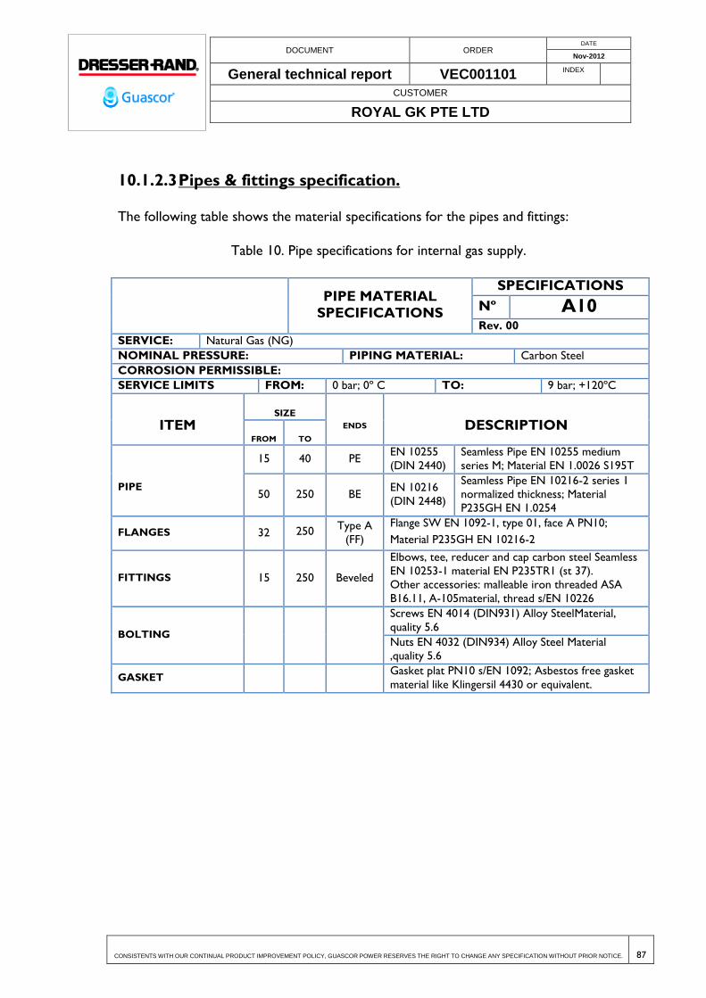
DOCUMENT ORDER DATE
Nov-2012
General technical report VEC001101 INDEX
CUSTOMER
ROYAL GK PTE LTD
CONSISTENTS WITH OUR CONTINUAL PRODUCT IMPROVEMENT POLICY, GUASCOR POWER RESERVES THE RIGHT TO CHANGE ANY SPECIFICATION WITHOUT PRIOR NOTICE. 87
10.1.2.3 Pipes & fittings specification.
The following table shows the material specifications for the pipes and fittings:
Table 10. Pipe specifications for internal gas supply.
PIPE MATERIAL
SPECIFICATIONS
SPECIFICATIONS
Nº A10 Rev. 00
SERVICE: Natural Gas (NG)
NOMINAL PRESSURE: PIPING MATERIAL: Carbon Steel
CORROSION PERMISSIBLE:
SERVICE LIMITS FROM: 0 bar; 0º C TO: 9 bar; +120ºC
ITEM SIZE
ENDS DESCRIPTION FROM TO
PIPE
15 40 PE EN 10255
(DIN 2440)
Seamless Pipe EN 10255 medium
series M; Material EN 1.0026 S195T
50 250 BE EN 10216
(DIN 2448)
Seamless Pipe EN 10216-2 series 1
normalized thickness; Material
P235GH EN 1.0254
FLANGES 32 250 Type A
(FF)
Flange SW EN 1092-1, type 01, face A PN10;
Material P235GH EN 10216-2
FITTINGS 15 250 Beveled
Elbows, tee, reducer and cap carbon steel Seamless
EN 10253-1 material EN P235TR1 (st 37).
Other accessories: malleable iron threaded ASA
B16.11, A-105material, thread s/EN 10226
BOLTING
Screws EN 4014 (DIN931) Alloy SteelMaterial,
quality 5.6
Nuts EN 4032 (DIN934) Alloy Steel Material
,quality 5.6
GASKET Gasket plat PN10 s/EN 1092; Asbestos free gasket
material like Klingersil 4430 or equivalent.
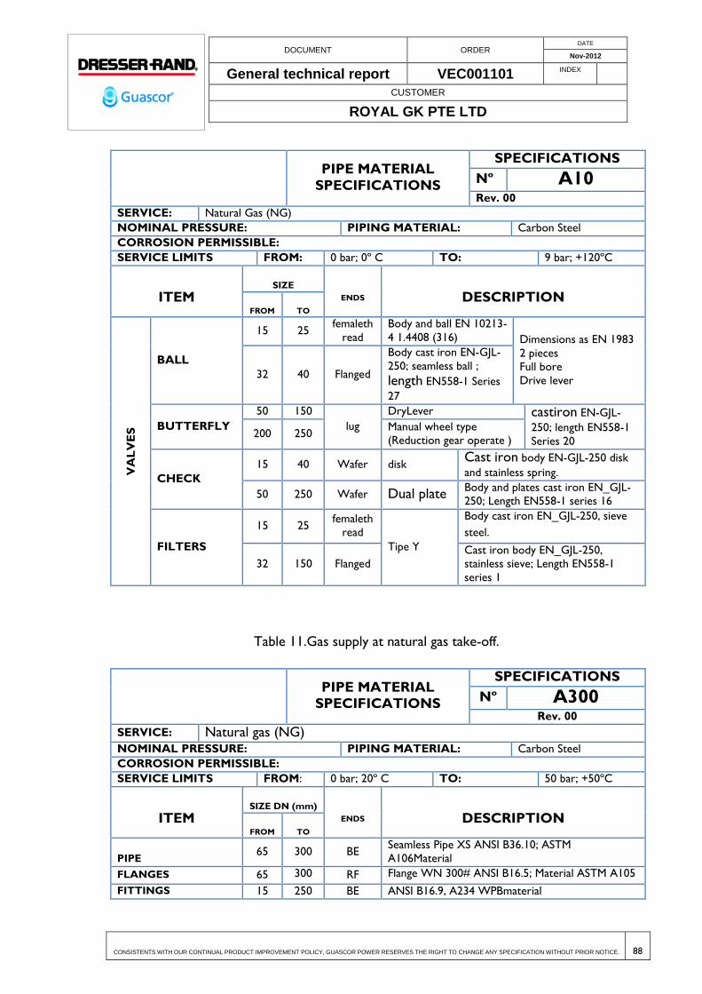
DOCUMENT ORDER DATE
Nov-2012
General technical report VEC001101 INDEX
CUSTOMER
ROYAL GK PTE LTD
CONSISTENTS WITH OUR CONTINUAL PRODUCT IMPROVEMENT POLICY, GUASCOR POWER RESERVES THE RIGHT TO CHANGE ANY SPECIFICATION WITHOUT PRIOR NOTICE. 88
PIPE MATERIAL
SPECIFICATIONS
SPECIFICATIONS
Nº A10 Rev. 00
SERVICE: Natural Gas (NG)
NOMINAL PRESSURE: PIPING MATERIAL: Carbon Steel
CORROSION PERMISSIBLE:
SERVICE LIMITS FROM: 0 bar; 0º C TO: 9 bar; +120ºC
ITEM SIZE
ENDS DESCRIPTION FROM TO
VA
LV
ES
BALL
15 25 femaleth
read Body and ball EN 10213-
4 1.4408 (316) Dimensions as EN 1983
2 pieces
Full bore
Drive lever 32 40 Flanged
Body cast iron EN-GJL-
250; seamless ball ;
length EN558-1 Series
27
BUTTERFLY
50 150
lug DryLever castiron EN-GJL-
250; length EN558-1
Series 20 200 250
Manual wheel type
(Reduction gear operate )
CHECK
15 40 Wafer disk Cast iron body EN-GJL-250 disk
and stainless spring.
50 250 Wafer Dual plate Body and plates cast iron EN_GJL-
250; Length EN558-1 series 16
FILTERS
15 25 femaleth
read
Tipe Y
Body cast iron EN_GJL-250, sieve
steel.
32 150 Flanged
Cast iron body EN_GJL-250,
stainless sieve; Length EN558-1
series 1
Table 11.Gas supply at natural gas take-off.
PIPE MATERIAL
SPECIFICATIONS
SPECIFICATIONS
Nº A300 Rev. 00
SERVICE: Natural gas (NG) NOMINAL PRESSURE: PIPING MATERIAL: Carbon Steel
CORROSION PERMISSIBLE:
SERVICE LIMITS FROM: 0 bar; 20º C TO: 50 bar; +50ºC
ITEM SIZE DN (mm)
ENDS DESCRIPTION FROM TO
PIPE 65 300 BE
Seamless Pipe XS ANSI B36.10; ASTM
A106Material
FLANGES 65 300 RF Flange WN 300# ANSI B16.5; Material ASTM A105
FITTINGS 15 250 BE ANSI B16.9, A234 WPBmaterial

DOCUMENT ORDER DATE
Nov-2012
General technical report VEC001101 INDEX
CUSTOMER
ROYAL GK PTE LTD
CONSISTENTS WITH OUR CONTINUAL PRODUCT IMPROVEMENT POLICY, GUASCOR POWER RESERVES THE RIGHT TO CHANGE ANY SPECIFICATION WITHOUT PRIOR NOTICE. 89
PIPE MATERIAL
SPECIFICATIONS
SPECIFICATIONS
Nº A300 Rev. 00
SERVICE: Natural gas (NG) NOMINAL PRESSURE: PIPING MATERIAL: Carbon Steel
CORROSION PERMISSIBLE:
SERVICE LIMITS FROM: 0 bar; 20º C TO: 50 bar; +50ºC
ITEM SIZE DN (mm)
ENDS DESCRIPTION FROM TO
Other accessories: malleable iron threaded ASA
B16.11, material A-105
BOLTING Screws ANSI B18.2.1, A 193 B7material
Nuts ANSI 18.2.2, material A194 2H
GASKET Gasket flat 300# ANSI B16.21; Asbestos free gasket
material like Klingersil 4430 or equivalent.
Table 12.Buried gas pipelines.
PIPE MATERIAL
SPECIFICATIONS
SPECIFICATIONS
Nº PE1 Rev. 00
SERVICE: Natural gas (NG)
NOMINAL PRESSURE: PIPING MATERIAL: Polyethylene
(HDPE) CORROSION PERMISSIBLE:
SERVICE LIMITS FROM: 0 bar; 0º C TO: 7 bar; +60ºC
ITEM SIZE
ENDS DESCRIPTION FROM TO
PIPE 15 250 PE Polyethylene (HDPE) PE80 S5/SDR11 UNE EN
1555
FLANGES 32 250 Type A
(FF)
Flange LJ EN 1092-1, type 04, face A PN10;
Aluminum Material
FITTINGS 15 250 BE
Bend 90º PE80 S5/SDR11 But fusion
Flange adaptor; PE100 S5/SDR11
BOLTING
Screws EN 4014 (DIN931) Alloy Steel Material,
quality 5.6
Nuts EN 4032 (DIN934) Alloy Steel Material,
quality 5.6
GASKET Gasket plate PN10 s/EN 1092; PTFE Material
DOCUMENT ORDER DATE
Nov-2012
General technical report VEC001101 INDEX
CUSTOMER
ROYAL GK PTE LTD
CONSISTENTS WITH OUR CONTINUAL PRODUCT IMPROVEMENT POLICY, GUASCOR POWER RESERVES THE RIGHT TO CHANGE ANY SPECIFICATION WITHOUT PRIOR NOTICE. 90
10.1.3 Engine gas trains
The description of the gas trains for the engines are shown in the plan 2.000553.040 of
the Genset Installation Manual
10.1.4 Identification of pipelines
The identification of gas pipelines will be according with the Standard UNE 1063and
which base color will be yellow.
10.2 ENGINEERING BASIS OF DESIGN
The installation for natural gas supply has been designed according to the following
standards and regulations:
UNE 60670, including all of its parts, Gas installations pipework supplied at
maximum operating pressure (MOP) up to and including 5 bar.
UNE 60620, including all of its parts, Natural gas receiving installations with
pressure supply over 5 bar.
UNE-EN 437, test gases – test pressures. Appliance categories.
UNE 1063, identification pipelines according to the fluid conveyed.
UNE 60305, steel gas pipelines, security areas and design factors.
UNE 60309, gas pipelines. Minimum wall thickness for steel pipes.
UNE 60311, gas supply systems. Pipelines for maximum operating pressure up to
and including 5 bar.
UNE-EN 1555, plastics piping systems for the supply of gaseous fuels. Polyethylene
(PE).
UNE-EN 12007, gas supply systems. Pipelines for maximum operating pressure up
to and including 16 bar.
2) Standards to take into account in the in site mechanical assembly of pipelines:

DOCUMENT ORDER DATE
Nov-2012
General technical report VEC001101 INDEX
CUSTOMER
ROYAL GK PTE LTD
CONSISTENTS WITH OUR CONTINUAL PRODUCT IMPROVEMENT POLICY, GUASCOR POWER RESERVES THE RIGHT TO CHANGE ANY SPECIFICATION WITHOUT PRIOR NOTICE. 91
UNE-EN ISO 15607 Specification and qualification of welding procedures for
metallic materials.
UNE-EN 287 Qualification test of welders
UNE-EN 25817 Arc-welded joints in steel. Guidance on quality levels for
imperfections (ISO 5817:1992).
UNE-EN ISO 13920 Welding. General tolerances for welded constructions.
Dimensions for lengths and angles. Shape and position. (ISO 13920:1996).
ASME Code.
UNE-EN 10255 Non-Alloy steel tubes suitable for welding and threading -
Technical delivery conditions.
UNE-EN 10216 Seamless steel tubes for pressure purposes - Technical delivery
conditions.
UNE-EN ISO 1127 Stainless steel tubes. Dimensions, tolerances and conventional
masses per unit length.
10.3 TESTING & INSPECTIONS
Following test will be done in the natural gas installation:
1) Mechanical strength testing;
i) Fluid ................................................................... N2 or Air (according to EN 437)
ii) Test pressure .............................................................................................. 4,2 bar g
iii) Test time ............................................................................................................ 1hour
2) Tightness testing:
i) Fluid ..................................................................... N2or Air (according to EN 437)
ii) Test pressure .................................................................................... at least 1 bar g
iii) Test time ........................................................................................................... 6 hour

DOCUMENT ORDER DATE
Nov-2012
General technical report VEC001101 INDEX
CUSTOMER
ROYAL GK PTE LTD
CONSISTENTS WITH OUR CONTINUAL PRODUCT IMPROVEMENT POLICY, GUASCOR POWER RESERVES THE RIGHT TO CHANGE ANY SPECIFICATION WITHOUT PRIOR NOTICE. 92
The test must be verified using an electronic or digital manometer of 0 to 10 bar range.
The time test could be of 10 minutes if the stretch is lower than 10 meters.
All components will be factory tested. However, a final test will be also carried out after
assembled on site.

DOCUMENT ORDER DATE
Nov-2012
General technical report VEC001101 INDEX
CUSTOMER
ROYAL GK PTE LTD
CONSISTENTS WITH OUR CONTINUAL PRODUCT IMPROVEMENT POLICY, GUASCOR POWER RESERVES THE RIGHT TO CHANGE ANY SPECIFICATION WITHOUT PRIOR NOTICE. 93
11 FIRE & GAS LEAK DETECTION SYSTEM
In this paragraph will be described the fire protection installed in the power plant.
The Fire gas & Gas leak detection system is described by the drawings 35-01 (layout of
detection equipment) and 27-02 (related electrical installations).The purpose of the
projected automatic fire detection system is to warn of the start of a fire in a timely and
efficient manner.
Basically, the fire detection system comprises the following elements as indicated in the
figure below:
A Sensors
B Control and signaling equipment
C Fire alarm devices
D Alarm buttons
E Fire alarm transmission device
F Fire alarm reception area
G Control of automatic fire protection systems
DOCUMENT ORDER DATE
Nov-2012
General technical report VEC001101 INDEX
CUSTOMER
ROYAL GK PTE LTD
CONSISTENTS WITH OUR CONTINUAL PRODUCT IMPROVEMENT POLICY, GUASCOR POWER RESERVES THE RIGHT TO CHANGE ANY SPECIFICATION WITHOUT PRIOR NOTICE. 94
H Automatic fire protection system
J Malfunction warning transmission device
K Malfunction warning reception area
l Power supply
Some of the elements indicated represent the most important parts of a fire detection
system. These are:
a) Fire sensors (fire alarm devices) and manual alarm button that are distributed
around the site and are capable of indicating the presence of a fire in its initial
phase.
b) Fire detection centre (control and signaling equipment) where the alarms are
centralized and a series of programmed preventive actions are carried out:
Acoustic transmission of alarm or any operation that may be started by
means of electrical transmission.
Transmission of emergency signals to a remote position located on the
Control Desk in order to control the site using graphs.
The installation of all of this equipment is subject to the standards and regulations that
describe in which type of premises their implementation is necessary, as well as the type
of sensor and their location being the most appropriate according to the nature of the
risks to be protected.
Following recommendations of a general nature, the installation of fire detection and
alarm shall comply with the following conditions:
a) There will be manual fire alarm buttons in the areas of circulation and inside
the premises.
b) Sensors that are appropriate to the type of fire expected inside the premises
and in the circulation areas shall be provided.

DOCUMENT ORDER DATE
Nov-2012
General technical report VEC001101 INDEX
CUSTOMER
ROYAL GK PTE LTD
CONSISTENTS WITH OUR CONTINUAL PRODUCT IMPROVEMENT POLICY, GUASCOR POWER RESERVES THE RIGHT TO CHANGE ANY SPECIFICATION WITHOUT PRIOR NOTICE. 95
The sensors shall be smoke sensors except in those areas in which thus type
of sensor could provoke false alarms, in which case heat or flame sensors will
be installed.
c) The control and signaling equipment shall have a device that will allow manual
and automatic activation of the alarm systems and will be located in a
permanently guarded place.
The automatic activation of the alarm systems must be adjustable so that it
takes place a maximum of 5 minutes after the activation of a sensor or a
button.
d) The alarm warning system will be acoustic and shall be comprised of two tone
sirens that will allow the transmission of local alarms and of a general alarm.
11.1 BASIS OF DESIGN
This project was completed in compliance with the following standards:
Technical Edification Code -CTE-. «Basic Document: SI Safety in the case of a
fire». ROYAL DECREE 314/2006, of 17th March 2006.
Regulation on Fire Protection Installations. ROYAL DECREE 1942/ 5th November
1993.
Regulation on Fire Safety in Industrial Establishments. ROYAL DECREE 2267/2004
of 3rd December 2004.
UNE Standard 23.007/1. Fire detection and alarm systems. Part 1. Introduction.
UNE Standard 23.007/2. Fire detection and alarm systems. Part 2. Control and
signaling equipment.
UNE Standard-EN 54/3. Fire detection and alarm systems. Part 3. Fire alarm
devices. Sound alarm devices.
DOCUMENT ORDER DATE
Nov-2012
General technical report VEC001101 INDEX
CUSTOMER
ROYAL GK PTE LTD
CONSISTENTS WITH OUR CONTINUAL PRODUCT IMPROVEMENT POLICY, GUASCOR POWER RESERVES THE RIGHT TO CHANGE ANY SPECIFICATION WITHOUT PRIOR NOTICE. 96
UNE Standard 23.007/4. Fire detection and alarm systems. Part 4. Power supply.
UNE Standard-EN 54/5. Fire detection and alarm systems. Part 5. Heat sensors.
Point sensors.
UNE Standard 23.007/7. Fire detection and alarm systems. Part 7. Smoke sensors.
Point sensors that work according to the principle of diffuse light, transmitted light
or by ionization.
UNE Standard 23.007/9. Fire detection and alarm systems. Part 9. Sensitivity tests
in households.
UNE Standard-EN 54/10. Fire detection and alarm systems. Part 10. Flame
sensors. Point sensors.
UNE Standard-EN 54/11. Fire detection and alarm systems. Part 11. Manual alarm
buttons.
UNE Standard-EN 54/12. Fire detection and alarm systems. Part 12. Line sensors
that use an optic light beam.
UNE Standard 23.007/13. Fire detection and alarm systems. Part 13. Evaluation of
the compatibility of the components of a system.
UNE Standard 23.007/14. Fire detection and alarm systems. Part 14. Planning,
design, installation, implementation, use and maintenance.
UNE Standard-EN 54/16. Fire detection and alarm systems. Part 16. Control of
the alarm by voice and indicating equipment.
UNE Standard-EN 54/17. Fire detection and alarm systems. Part 17. Short circuit
isolators.
UNE Standard-EN 54/18. Fire detection and alarm systems. Part 18. Input /Output
devices.
UNE Standard EN 54/20. Components of the automatic fire detection systems.
Part 20. Smoke aspiration sensors.
UNE Standard-EN 54/21. Fire detection and alarm systems. Part 21. Alarm
transmission equipment and warnings of failures.
DOCUMENT ORDER DATE
Nov-2012
General technical report VEC001101 INDEX
CUSTOMER
ROYAL GK PTE LTD
CONSISTENTS WITH OUR CONTINUAL PRODUCT IMPROVEMENT POLICY, GUASCOR POWER RESERVES THE RIGHT TO CHANGE ANY SPECIFICATION WITHOUT PRIOR NOTICE. 97
UNE Standard-EN 54/24. Fire detection and alarm systems. Part 24. Components
of the voice alarm systems. Loudspeakers.
UNE Standard-EN 54/25. Fire detection and alarm systems. Part 25. Components
that use radioelectrical links.
UNE Standard-EN 12.094/1. Fixed fire protection systems. Components for fire
extinguishing using gas agents. Part 1. Test requisites and methods for automatic
and electrical control and delay devices.
UNE Standard-EN 12.094/3. Fixed fire protection systems. Components for fire
extinguishing using gas agents. Part 1. Test requisites and methods for manual trip
and shutdown devices.
Municipal ordinances and standards from the regional authorities on Fire
Protection Conditions.
Low Voltage Electrotechnical Regulation and Complementary Technical
Instructions.
The system will also be designed in accordance with the following recommendations:
Technical Rule CEPREVEN R.T.3.-DET. Technical Rule for Automatic
Fire Detection installations.
11.2 DESIGN & DEFINITION
11.2.1 Smoke and heat point sensors
The number of smoke and heat point sensors is determined in accordance with the
stipulations of UNE Standard 23007/14, Annex A.
The sensors must be located such that their sensitive elements are less than 5% from the
top of the room. Due to the possible existence of a cold limit layer, the sensors shall not
be embedded in the ceiling. The heat sensors must be located below under the ceiling.
For point sensors the indication is that they must be distributed in such a way that no
point of the ceiling or of the roof is at a horizontal distance from the sensor greater than
the values of Dmax indicated in table A.1.
DOCUMENT ORDER DATE
Nov-2012
General technical report VEC001101 INDEX
CUSTOMER
ROYAL GK PTE LTD
CONSISTENTS WITH OUR CONTINUAL PRODUCT IMPROVEMENT POLICY, GUASCOR POWER RESERVES THE RIGHT TO CHANGE ANY SPECIFICATION WITHOUT PRIOR NOTICE. 98
If there are unfavourable temperature gradients on the protected surface, the plume of
cloud rising from the fire can be suffocated and form a layer before reaching the ceiling. If
the height of this layer is foreseeable, sensors can be installed at the expected
stratification height as well as those sensors that are installed near the ceiling.
In narrow corridors and ceiling spaces that have a width of less than 3 metres, the
distances between sensors may be as follows:
- For heat sensors, up to 10m (5m for detection with coincidences or for
extinguishing systems);
- For smoke sensors, up to 15m (11m for detection with coincidences or
7.5m for extinguishing systems).
The horizontal distance between the sensor and the wall or the ceiling must not be
greater than half of the above mentioned distances.
The maximum area of authorized monitoring must not be greater than the added values
indicated in Table A.1.
Table 13.Distribution of smoke and heat point sensors.
Surface of the
premises in m2
Type of sensor
Height of the
premises in m
Slope ≤ 20º Slope >20º
Sv (m2) Dmax (m) Sv (m2) Dmax (m)
SL ≤ 80 UNE-EN54/7 h ≤ 12 80 6.6 80 8.2
SL > 80 UNE-EN54/7 h ≤ 6 60 5.7 90 8.7
6 < h ≤ 12 80 6.6 110 9.6
SL > 30
UNE-EN54/5, class A1 h ≤ 7,5 20 3.5 40 6.5
UNE-EN54/5, class A2,
B, C, D, E, F, G h ≤ 6 20 3.5 40 6.5
SL ≤ 30
UNE-EN54/5, class A1 h ≤ 7,5 30 4.4 30 5.7
UNE-EN54/5, class A2,
B, C, D, E, F, G h ≤ 6 30 4.4 30 5.7
DOCUMENT ORDER DATE
Nov-2012
General technical report VEC001101 INDEX
CUSTOMER
ROYAL GK PTE LTD
CONSISTENTS WITH OUR CONTINUAL PRODUCT IMPROVEMENT POLICY, GUASCOR POWER RESERVES THE RIGHT TO CHANGE ANY SPECIFICATION WITHOUT PRIOR NOTICE. 99
Dmax
Incorrectdistribution Normal distribution Reduceddistribution
Key
Sv Monitored surface
Dmax Max.horizontal distance from any point to the sensor
Dmax

DOCUMENT ORDER DATE
Nov-2012
General technical report VEC001101 INDEX
CUSTOMER
ROYAL GK PTE LTD
CONSISTENTS WITH OUR CONTINUAL PRODUCT IMPROVEMENT POLICY, GUASCOR POWER RESERVES THE RIGHT TO CHANGE ANY SPECIFICATION WITHOUT PRIOR NOTICE. 100
The SV monitoring area must be corrected according to the type of risk. Thus, the area
protected by sensors used in coinciding detection must be reduced by at least 30% and
for sensors aimed at activating a fixed extinguishing system it must be reduced by at least
50%.
A space of at least 0.5m must be left in all directions below each sensor.
11.2.2 Linear sensors
The lineal sensors comply with UNE 23007/12.
The distance between the emitter and the receiver shall vary between 10 metres as a
minimum and 100 m as a maximum.
The maximum distance of lateral cover of the ray is that indicated by the following table
extracted from UNE 23007.14:

DOCUMENT ORDER DATE
Nov-2012
General technical report VEC001101 INDEX
CUSTOMER
ROYAL GK PTE LTD
CONSISTENTS WITH OUR CONTINUAL PRODUCT IMPROVEMENT POLICY, GUASCOR POWER RESERVES THE RIGHT TO CHANGE ANY SPECIFICATION WITHOUT PRIOR NOTICE. 101
Table 14.Maximum distance.
Type of
sensor Height of premises
in m
Distance in m,
D
Distance in m,
A
Maximum covered surface
in m2
Slope ≤
20º
Slope
>20º
Dv (m) Dv (m)
UNE-
EN54/12 h ≤ 6 100 12 1200 0.3 a 0.5 0.3 a 0.5
UNE-
EN54/12 6 < h ≤ 12 100 13 1300 0.4 a 0.6 0.5 a 0.8
UNE-
EN54/12 12 < h ≤ 25 100 15 1500 0.4 a 0.6 0.5 a 0.8
Key
D, maximum distance covered by the beam from the barrier
A, maximum distance between to lineal sensors
Dv, vertical distance from the beam of the barrier to the ceiling
In order to calculate the required number of elements we will have to take into account
their maximum area of coverage and the maximum lateral distance between sensors.
In the case of sloped ceilings, the lateral distance between lineal sensors will start to
count from the lintel where one device must be placed and measure between barriers
using it as a reference.
For buildings with ceiling with special forms such as saw tooth ceilings, a set of sensors
shall be installed for each tooth.
The sensor will be located at a distance from the ceiling between 0.3 and 0.8 m depending
on the height of the building, in order to avoid the thermal cushion of hot air.
11.2.3 Buttons
The distribution of buttons shall take into account the rules laid down in UNE-23007-14:
The buttons are located in such a way that it will not be necessary to move more
than 25 metres to reach one. In those premises in which the users may be
disabled, this distance should be reduced.
They are located at between 1.2 and 1.6 m from the floor.

DOCUMENT ORDER DATE
Nov-2012
General technical report VEC001101 INDEX
CUSTOMER
ROYAL GK PTE LTD
CONSISTENTS WITH OUR CONTINUAL PRODUCT IMPROVEMENT POLICY, GUASCOR POWER RESERVES THE RIGHT TO CHANGE ANY SPECIFICATION WITHOUT PRIOR NOTICE. 102
11.2.4 Sound alarms
These elements are distributed in such a way that guarantees the minimum sound levels
expressed in UNE Standard 23007-14.
The sound level of the alarm shall be at least 65 dB(A) or 5 dB(A) above any
sound that is expected to last more than 30 s.
If the idea of the alarm is to wake people who are asleep, the minimum sound
level shall be 75 dB(A).
This minimum level must be guaranteed in all parts of the enclosure.
The sound level must not exceed 120 dB(A) at any point which is more than 1m
from the device.
The number of devices to be installed will be determined in accordance with the
following:
The number of sirens/bells must be sufficient to reach the above mentioned sound level.
The minimum number of devices will be two per building and one per fire sector.
In order to avoid excessive levels in some areas it is preferable to place more sirens with
less power.
The tone used by the sirens to warn of a fire must be exclusive for that purpose.

DOCUMENT ORDER DATE
Nov-2012
General technical report VEC001101 INDEX
CUSTOMER
ROYAL GK PTE LTD
CONSISTENTS WITH OUR CONTINUAL PRODUCT IMPROVEMENT POLICY, GUASCOR POWER RESERVES THE RIGHT TO CHANGE ANY SPECIFICATION WITHOUT PRIOR NOTICE. 103
11.2.5 Cabling
The following specifications indicated in the Electrotechnical Low Voltage Regulation
were taken into account in the installation of the cabling required for the connection of
the elements with the control desk.
A braid shield wire with the following characteristics will be used as a communications
bus for the smart elements:
cable: braided and shielded for two wires.
braid: with 20 to 40 turns per meter.
shield: Mylar aluminum with drain wire.
total resistance of the loop cable: less than 40 ohms.
capacity: less than 0.5 microfarads.
The cable section was selected in accordance with the following table:
Length of loop Section
up to 1500 metres 2 x 1.5 mm2
up to 2200 metres 2 x 2.5 mm2
The power cable of the auxiliary equipment is a conventional single wire type. In order to
calculate the section required we will calculate the voltage drops in accordance with the
formula:
E=2PL/KSv
Where: e: voltage drop in volts
P: is power P= V x i
L: is the length of the cable in meters
k: for copper 56 and for aluminum 35
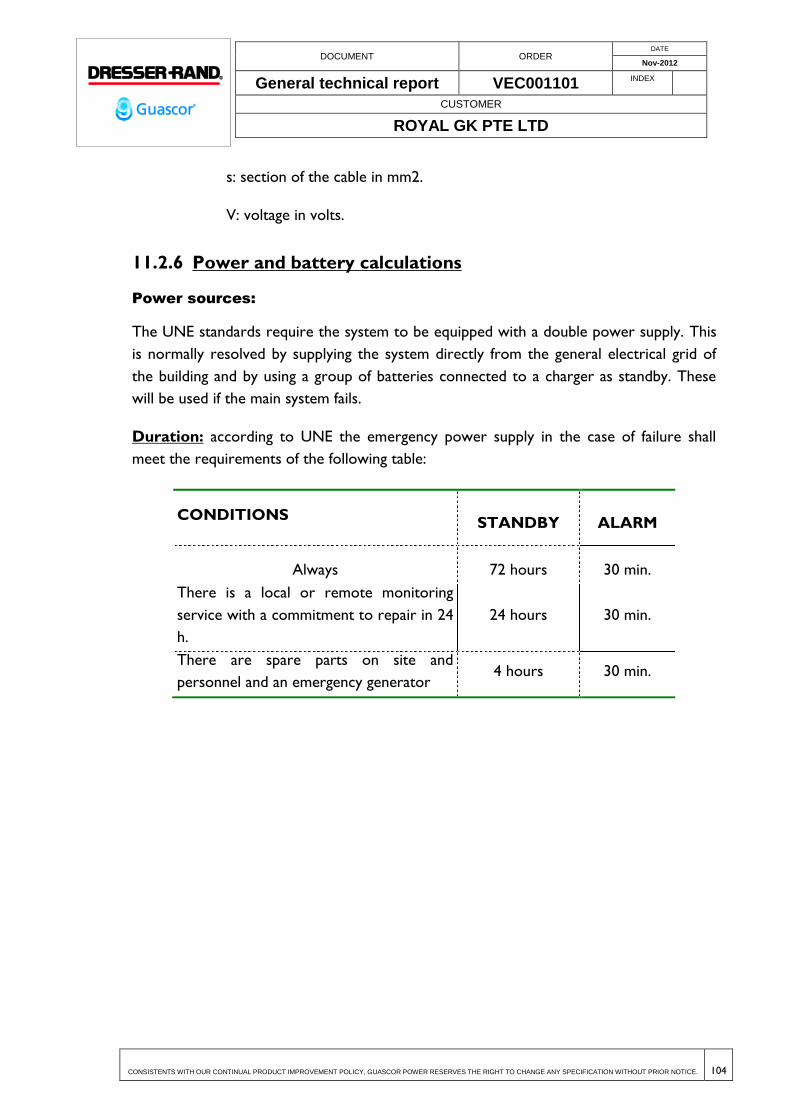
DOCUMENT ORDER DATE
Nov-2012
General technical report VEC001101 INDEX
CUSTOMER
ROYAL GK PTE LTD
CONSISTENTS WITH OUR CONTINUAL PRODUCT IMPROVEMENT POLICY, GUASCOR POWER RESERVES THE RIGHT TO CHANGE ANY SPECIFICATION WITHOUT PRIOR NOTICE. 104
s: section of the cable in mm2.
V: voltage in volts.
11.2.6 Power and battery calculations
Power sources:
The UNE standards require the system to be equipped with a double power supply. This
is normally resolved by supplying the system directly from the general electrical grid of
the building and by using a group of batteries connected to a charger as standby. These
will be used if the main system fails.
Duration: according to UNE the emergency power supply in the case of failure shall
meet the requirements of the following table:
CONDITIONS STANDBY ALARM
Always 72 hours 30 min.
There is a local or remote monitoring
service with a commitment to repair in 24
h.
24 hours 30 min.
There are spare parts on site and
personnel and an emergency generator 4 hours 30 min.

DOCUMENT ORDER DATE
Nov-2012
General technical report VEC001101 INDEX
CUSTOMER
ROYAL GK PTE LTD
CONSISTENTS WITH OUR CONTINUAL PRODUCT IMPROVEMENT POLICY, GUASCOR POWER RESERVES THE RIGHT TO CHANGE ANY SPECIFICATION WITHOUT PRIOR NOTICE. 105
Calculation of the capacity:
The following formula was used to calculate:
Cmin = (A1 x t1 + A2 x t2) ampshour
where: t1 and t2 are the operating times on idle and on alarm respectively.
A1 and A2 are the consumptions of the system in amps on standby and
alarm..
25% extra should be considered for the ageing of the batteries which means that the total
capacity will be: 1.25 x Cmin.
For the calculation of A1, we add the consumptions of all the elements that make up the
detection system and in order to determine A2, we calculate the consumption in alarm of
all the elements that intervene simultaneously.
11.3 TECHNICAL SPECIFICATIONS
11.3.1 Smart analogical centres / accessories
11.3.1.1 Fire Detection Centre. ID3002
The analogical and algorithmic fire detection centre may be configured to be adapted to
the needs of each site. The size of the system will be defined by the number of loops (2
loops, 396 points of detection/control, individually identifiable and controllable).
Each loop will support 99 analogical sensors plus 99 programmable modules complying
with the requisites of EN 54 A and B cabling standards. It will be able to support sensors
of the following types: ionic, photo-electrical photo-thermal, high sensitivity lasers,
thermal and analogical sensors of an ionic or photo-electrical type. The modules can be:
programmable monitors for NA or NC contact reading, control modules for
programmable outputs, short circuit isolating modules and conventional area monitor
sensor modules.
Characteristics of the System
Automatic compensation of the dirt in the analogical smoke sensors.

DOCUMENT ORDER DATE
Nov-2012
General technical report VEC001101 INDEX
CUSTOMER
ROYAL GK PTE LTD
CONSISTENTS WITH OUR CONTINUAL PRODUCT IMPROVEMENT POLICY, GUASCOR POWER RESERVES THE RIGHT TO CHANGE ANY SPECIFICATION WITHOUT PRIOR NOTICE. 106
Function for automatic adaptation of each sensor to the environment.
10 levels of sensitivity.
AWACS algorithms for the control and stability of the sensors.
Automatic or manual testing of the system that activates and verifies each system
sensor.
Completely programmable and configurable in the field from the panel keyboard. It
will not require a special computer. It will allow automatic programming by default.
Customized messages for each point.
Programmable functions by events:
Predefined programming blocks.
Monitoring / interlocking selection.
Management of no alarm points (low priority).
Time function control for actions on a specific day and time.
Programming delays and output pulse times.
Historical archive in non volatile memory of 600 events which can be viewed on
screen or printed.
Non volatile clock for indicating the date and time of all events.
Uploading and downloading program using a PC.
Three levels of access with different and selectable passwords.
Self programming of the elements of the loops.
Operation test with an equipment meter and identification of 2 sensors assigned to
the same address. While the test is being carried out on the rest of the system it still
provides fire protection. Timer to stop the test.
Automatic maintenance alert function for sensors that are dirty before a false alarm
occurs.
Manual or automatic adjustment of the day/night sensitivity of the sensors.

DOCUMENT ORDER DATE
Nov-2012
General technical report VEC001101 INDEX
CUSTOMER
ROYAL GK PTE LTD
CONSISTENTS WITH OUR CONTINUAL PRODUCT IMPROVEMENT POLICY, GUASCOR POWER RESERVES THE RIGHT TO CHANGE ANY SPECIFICATION WITHOUT PRIOR NOTICE. 107
Enabling and disabling of all equipment.
Status report for all the system equipment including sensitivity and check totalizer.
Programmable silencer, alarm silence and alarm check.
High efficiency 24 V and 2.5 amp power supply
Liquid crystal screen with 240 x 64 pixels living complete on screen information about
the system.
30 key alphanumerical keyboard.
11.3.2 Smart analogical sensors
11.3.2.1 Super flat Analogical Optic Smoke Sensor. NFX/ISO-OPT
The white coloured analogical photo electrical smoke sensor with isolator will have an
optic sensor camera and will use the dispersion of light as its main principle for detection.
It detects the presence of smoke through the light dispersed by the smoke particles inside
the camera of the sensor.
Associated with the photoelectrical sensor, is the recognition circuit that provides a
threshold for a predetermined level of smoke in the system initialisation circuit.
The direction of each sensor will be assigned by rotating switches. Each sensor reports its
direction, its type and its analogical type in order to give an idea of the measured value
and its status.
The sensor will have two LEDS, which make it possible to see its status from any
position. The LEDS will flash in normal operation and remain on in the case of an alarm.
As an option, flashing can be eliminated when the system is used in rooms.
It includes a micro switch that is activated by a magnet to check that the equipment alarm
works.
The sensors will be assembled on a common bayonet type base with an interlocking
device to prevent their accidental extraction. They may be assembled on a base with a
built in horn to provide a local acoustic indication.
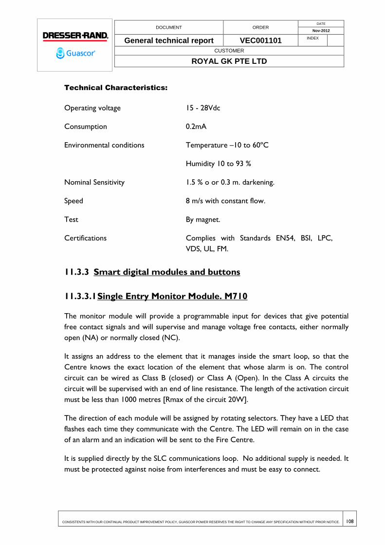
DOCUMENT ORDER DATE
Nov-2012
General technical report VEC001101 INDEX
CUSTOMER
ROYAL GK PTE LTD
CONSISTENTS WITH OUR CONTINUAL PRODUCT IMPROVEMENT POLICY, GUASCOR POWER RESERVES THE RIGHT TO CHANGE ANY SPECIFICATION WITHOUT PRIOR NOTICE. 108
Technical Characteristics:
Operating voltage 15 - 28Vdc
Consumption 0.2mA
Environmental conditions Temperature –10 to 60ºC
Humidity 10 to 93 %
Nominal Sensitivity 1.5 % o or 0.3 m. darkening.
Speed 8 m/s with constant flow.
Test By magnet.
Certifications Complies with Standards EN54, BSI, LPC,
VDS, UL, FM.
11.3.3 Smart digital modules and buttons
11.3.3.1 Single Entry Monitor Module. M710
The monitor module will provide a programmable input for devices that give potential
free contact signals and will supervise and manage voltage free contacts, either normally
open (NA) or normally closed (NC).
It assigns an address to the element that it manages inside the smart loop, so that the
Centre knows the exact location of the element that whose alarm is on. The control
circuit can be wired as Class B (closed) or Class A (Open). In the Class A circuits the
circuit will be supervised with an end of line resistance. The length of the activation circuit
must be less than 1000 metres [Rmax of the circuit 20W].
The direction of each module will be assigned by rotating selectors. They have a LED that
flashes each time they communicate with the Centre. The LED will remain on in the case
of an alarm and an indication will be sent to the Fire Centre.
It is supplied directly by the SLC communications loop. No additional supply is needed. It
must be protected against noise from interferences and must be easy to connect.

DOCUMENT ORDER DATE
Nov-2012
General technical report VEC001101 INDEX
CUSTOMER
ROYAL GK PTE LTD
CONSISTENTS WITH OUR CONTINUAL PRODUCT IMPROVEMENT POLICY, GUASCOR POWER RESERVES THE RIGHT TO CHANGE ANY SPECIFICATION WITHOUT PRIOR NOTICE. 109
It includes a micro switch which is activated by a magnet to check that the alarm is
working. It has an isolator at both loop inlets. Programmable action.Possibility of assembly
on a DIN rail using the M200DIN accessory.
Technical Characteristics:
Consumption: 2.8 mA on alarm, 660 μAin normal conditions
Environmental conditions: Temperature: -20 to 60ºC
Humidity: 5 to 95%, not condensed.
Dimensions: 93mm (height) x 94mm (width) x 23mm
Certifications: Complies with standards prEN 54-17, Vds 2489,
approved by CEA GEI 1-082 and GEI 1-084.
11.3.3.2 6 Relay output Control Module. CR6
The control module will provide up to six output orders to elements such as sirens,
electromagnets, etc. The connection of each circuit must be voltage free using a double
NA/NC contact.
Each output will have a direction assigned, using rotating selectors so that when it
receives an order from the Centre, its internal relay is activated and will switch to NA or
NC.
The control module will act on each of the relays in the cases indicated. The relay
contacts are of the SPDT type and set at 28 vdc and 2A.
There is a LED for each direction that flashes each time it communicates with the centre.
The LED remains on in the case of an alarm and indicates it to the Fire Centre.
The direction of each module will be assigned using rotating selectors.
Technical Characteristics:
Consumption: 7.6 mA on alarm, 1.45 mA in normal conditions.
Contacts: NA/NC, 2A to 28Vdc, 0,35 power factor.

DOCUMENT ORDER DATE
Nov-2012
General technical report VEC001101 INDEX
CUSTOMER
ROYAL GK PTE LTD
CONSISTENTS WITH OUR CONTINUAL PRODUCT IMPROVEMENT POLICY, GUASCOR POWER RESERVES THE RIGHT TO CHANGE ANY SPECIFICATION WITHOUT PRIOR NOTICE. 110
Environmental conditions: Temperature: -10 to 49ºC
Humidity: 10 to 93%, not condensed.
Dimensions: 185mm (height) x 147mm (width) x 25mm (depth)
Certifications: Complies with standards EN 54.
11.3.3.3 Programmable button. M700KAC-IFF/C
Manual alarm button assembled on a plastic red box made with impact resistant synthetic
material. It will be resettable and will have an in built short circuit isolator. It will have a
plastic cover or similar and shall have a key for testing. It will be surface mounted.
Certified in accordance with EN54 part 11.
It shall have extractable terminals to facilitate installation.
The direction of each button will be assigned using rotating selectors.
The button will have an LED that flashes each time it communicates with the centre. This
LED will go remain on when an alarm condition is detected.
Protection level IP44.
Technical Characteristics (Monitor) Module:
Consumption 7.6 mA on alarm, 160 A in normal conditions
Temperature conditions: Temperature: -10 to 49ºC
Humidity: 10 a 93%, non condensing
Certifications: Complies with standards EN54.
DOCUMENT ORDER DATE
Nov-2012
General technical report VEC001101 INDEX
CUSTOMER
ROYAL GK PTE LTD
CONSISTENTS WITH OUR CONTINUAL PRODUCT IMPROVEMENT POLICY, GUASCOR POWER RESERVES THE RIGHT TO CHANGE ANY SPECIFICATION WITHOUT PRIOR NOTICE. 111
11.3.4 Infrared barriers
11.3.4.1 Infrared Light reflection analogical smoke sensor
The linear optic beam reflector type analogical smoke sensorLPB700T is
compatible with all of the Notifier ID Seriescentres. Based on the principle of
darkening, it uses an infrared light beam. Optic beam smoke sensors are especially
appropriate for the protection of large areas, for example: industrial warehouses,
theatres, buildings with very high roofs where the installation of point sensors is not easy.
The LPB700Tsensor includes a transmitter and a receiver in the same unit and can
be connected directly to the analogical Notifier programmable loop without the need to
have an external power source, which is a considerable saving in the cost of installation as
it is only necessary to wire the emitter/receiver unit.
The infrared transmitter generates an invisible ray of light that towards the high
efficiency reflector and it returns the beam to the receiver of the LPB700Tsensor where
an analysis is made of the signal received. The change in the power of the signal received
determines the condition of the alarm.
The sensitivity of the sensors can be adjusted between 25% and 50% darkness. This
option makes it more adaptable to the different environments in which it is installed. As
well as the four fixed alarm thresholds, the sensor can be programmed to adjust
automatically to the environmental changes, within a known range of sensitivity, thus
reducing the number of possible unwanted alarms that could be generated because of
local activities in the protected area.
The LPB700T sensor is equipped with automatic dirt compensation, which means
that it will adapt its detection thresholds according to the signals received from the beam
caused by environmental contaminants. Once the sensor reaches its compensation limit,
the panel can identify and signal this condition.

DOCUMENT ORDER DATE
Nov-2012
General technical report VEC001101 INDEX
CUSTOMER
ROYAL GK PTE LTD
CONSISTENTS WITH OUR CONTINUAL PRODUCT IMPROVEMENT POLICY, GUASCOR POWER RESERVES THE RIGHT TO CHANGE ANY SPECIFICATION WITHOUT PRIOR NOTICE. 112
LPB700T lineal beam analogical reflection smoke sensor with an integrated
sensitivity test function.
Technical Characteristics:
Operating voltage 15-32 Vdc (15-28 Vdc with isolators)
Consumption Idle 2 mA.
Alarm 8.5 mA
Alignment 20 mA
Environmental Conditions Temperature -30 to 55ºC
Humidity 10% to 95% without condensation
Sensitivity 6 levels of sensitivity.
Certifications Complies with standard EN54/12
11.3.5 Warning elements
11.3.5.1 Alarm siren and loop flash. AWSB32/R/R-I
Siren with flash and isolator included, individually programmable, connected directly to
the communications loop of the analogical systems. Two rotating selectors are used for
direction. It will use the supply of the analogical loop. Certified in accordance with the
requirements of EN54 standard, Part 3.
3 different volume adjustments can be selected using the micro switch. Capability for 32
different tones.
The ABSB32/W/C-I model will allow for a base to be assembled on the siren forming a
sensor-siren set.
AWSB32/R/R-I.Supplied from analogical loop. Compatible with ID50, ID60, ID3002 and
ID3000 centers
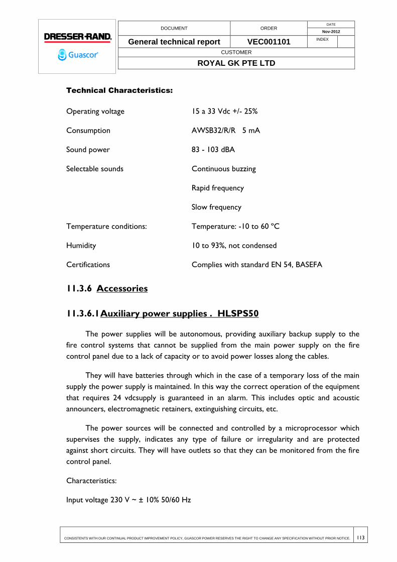
DOCUMENT ORDER DATE
Nov-2012
General technical report VEC001101 INDEX
CUSTOMER
ROYAL GK PTE LTD
CONSISTENTS WITH OUR CONTINUAL PRODUCT IMPROVEMENT POLICY, GUASCOR POWER RESERVES THE RIGHT TO CHANGE ANY SPECIFICATION WITHOUT PRIOR NOTICE. 113
Technical Characteristics:
Operating voltage 15 a 33 Vdc +/- 25%
Consumption AWSB32/R/R 5 mA
Sound power 83 - 103 dBA
Selectable sounds Continuous buzzing
Rapid frequency
Slow frequency
Temperature conditions: Temperature: -10 to 60 ºC
Humidity 10 to 93%, not condensed
Certifications Complies with standard EN 54, BASEFA
11.3.6 Accessories
11.3.6.1 Auxiliary power supplies . HLSPS50
The power supplies will be autonomous, providing auxiliary backup supply to the
fire control systems that cannot be supplied from the main power supply on the fire
control panel due to a lack of capacity or to avoid power losses along the cables.
They will have batteries through which in the case of a temporary loss of the main
supply the power supply is maintained. In this way the correct operation of the equipment
that requires 24 vdcsupply is guaranteed in an alarm. This includes optic and acoustic
announcers, electromagnetic retainers, extinguishing circuits, etc.
The power sources will be connected and controlled by a microprocessor which
supervises the supply, indicates any type of failure or irregularity and are protected
against short circuits. They will have outlets so that they can be monitored from the fire
control panel.
Characteristics:
Input voltage 230 V ~ ± 10% 50/60 Hz
DOCUMENT ORDER DATE
Nov-2012
General technical report VEC001101 INDEX
CUSTOMER
ROYAL GK PTE LTD
CONSISTENTS WITH OUR CONTINUAL PRODUCT IMPROVEMENT POLICY, GUASCOR POWER RESERVES THE RIGHT TO CHANGE ANY SPECIFICATION WITHOUT PRIOR NOTICE. 114
Maximum absorbed current 0.5 A; 0.9 A; 1.8 A
Output voltage 27.6 V ± 1%
Nominal current 1.4 A2.5 A5.0 A
Maximum current supplied 1,2 A; 2.0 A; 4.0 A
Maximum current per output 1.8 A
Autonomy with a 2A charge 8 hours
Battery box 2 x (12 V 17 Ah)
Voltage thresholds: 22 V to 34 V
Charger cut off threshold 19 V
Operating temperature 5 to 40º C
Isolation level Class I
11.3.6.2 Fire resistant cable . 2x1,5 LHR
It must be capable of resisting the effects of the fire for at least 30 minutes as indicated in
standard UNE 23007-14 section A.6.11.3.
The cable will be red and will be made of flexible polished copper, class 1, fire resistant,
free from halogens, low smoke emission and low corrosiveness.
Characteristics:
Class 1 polished copper wire
Silicon isolator
Nominal isolation thickness 0.7
Drainage of rigid tinned copper 0.50 mm2.
Electrical resistance of the wire at 20 ºC ( /Km) 13.1
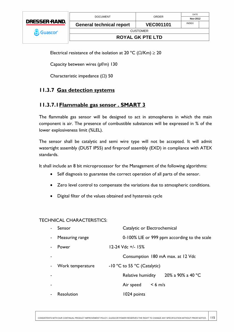
DOCUMENT ORDER DATE
Nov-2012
General technical report VEC001101 INDEX
CUSTOMER
ROYAL GK PTE LTD
CONSISTENTS WITH OUR CONTINUAL PRODUCT IMPROVEMENT POLICY, GUASCOR POWER RESERVES THE RIGHT TO CHANGE ANY SPECIFICATION WITHOUT PRIOR NOTICE. 115
Electrical resistance of the isolation at 20 ºC ( /Km) 20
Capacity between wires (pf/m) 130
Characteristic impedance ( ) 50
11.3.7 Gas detection systems
11.3.7.1 Flammable gas sensor . SMART 3
The flammable gas sensor will be designed to act in atmospheres in which the main
component is air. The presence of combustible substances will be expressed in % of the
lower explosiveness limit (%LEL).
The sensor shall be catalytic and semi wire type will not be accepted. It will admit
watertight assembly (DUST IP55) and fireproof assembly (EXD) in compliance with ATEX
standards.
It shall include an 8 bit microprocessor for the Management of the following algorithms:
Self diagnosis to guarantee the correct operation of all parts of the sensor.
Zero level control to compensate the variations due to atmospheric conditions.
Digital filter of the values obtained and hysteresis cycle
TECHNICAL CHARACTERISTICS:
- Sensor Catalytic or Electrochemical
- Measuring range 0-100% LIE or 999 ppm according to the scale
- Power 12-24 Vdc +/- 15%
- Consumption 180 mA max. at 12 Vdc
- Work temperature -10 ºC to 55 ºC (Catalytic)
- Relative humidity 20% a 90% a 40 ºC
- Air speed < 6 m/s
- Resolution 1024 points

DOCUMENT ORDER DATE
Nov-2012
General technical report VEC001101 INDEX
CUSTOMER
ROYAL GK PTE LTD
CONSISTENTS WITH OUR CONTINUAL PRODUCT IMPROVEMENT POLICY, GUASCOR POWER RESERVES THE RIGHT TO CHANGE ANY SPECIFICATION WITHOUT PRIOR NOTICE. 116
- Stability time < 1 hour
- Repetition +/- 1.5 % F.S.

DOCUMENT ORDER DATE
Nov-2012
General technical report VEC001101 INDEX
CUSTOMER
ROYAL GK PTE LTD
CONSISTENTS WITH OUR CONTINUAL PRODUCT IMPROVEMENT POLICY, GUASCOR POWER RESERVES THE RIGHT TO CHANGE ANY SPECIFICATION WITHOUT PRIOR NOTICE. 117
12 ELECTRICAL GENERATING SYSTEM
12.1 GENERAL DESCRIPTION
The power plant will consist of twenty-six generators of 1 MW and 400V that supply
electric power to a 33 kV network through a power line from a switching substation
The connection point with MV distribution network begins in the incoming switchgear
stall. It is a room which houses the input cabinet and two additional cabinets for
protection of insulation transformers.
Because of existing short circuit power of the public network nd potential increase in the
future, it was decided to install 2 insulation transformers of 35 MVA and 33.000/33.000 V.
One of them will be for stand-by.
From these transformers two lines are connected to a main cabinet room. These lines
enter in a protection cabinet in which busbars are connected to the protection cabinet of
13 step-up transformers for gensets and one protection cabinet for auxiliary services of
power plant.
The step-up transformers are provided in low voltage end with two connection busbars.
Step-up transformers are of 2500/1250/1250 KVA and 33000/400-400V. Each busbar is
connected to a genset.
Each genset is operated through a control and protection switchboard cabinet in which a
system for synchronization with network and management switch is located.
12.1.1 Connection line to company power substation of 33 kV
The connection line to the overhead power line of the company consists of a circuit
provided with 3(2(1x240) mm2 Cu 19/33 kV CU/XLPE/CU TAPE/PVC/AWA/PVC cables.
The line will be laid in pipes from the substation. The line will come protected against
overvoltage from the substation.
Main features of cables:
1) Insulation: .......................................................................................... 19/33 kV
2) Cross-section (mm2):................................................................................ 240

DOCUMENT ORDER DATE
Nov-2012
General technical report VEC001101 INDEX
CUSTOMER
ROYAL GK PTE LTD
CONSISTENTS WITH OUR CONTINUAL PRODUCT IMPROVEMENT POLICY, GUASCOR POWER RESERVES THE RIGHT TO CHANGE ANY SPECIFICATION WITHOUT PRIOR NOTICE. 118
3) Number of cables per phase: ...................................................................... 2
4) Approximate permissible current (A): ................................................. 750
5) Conductor: .......................................................... Stranded Copper Wires
6) Conductor screen ....................................... Semi-conductive compound
7) Insulation: ............................................ Cross-linked polyethylene (XLPE)
8) Insulation screen ...................... Strippable Semi-conducting compound
9) Screen Layer ........................................................................... Copper Tape.
10) Separation sheath ............................................................ Polyvinyl chloride
11) Armor .................................................................................. Aluminum wires
12) Binder ............................................................................................ Binder tape
13) Outer sheath ...................................................... Polyvinyl chloride - Black
12.1.2 Incoming switchgear stall
The line from the substation enters in C17cabinet, and is connected to the busbars in
protection cabinet for the two insulation transformers of 35 MVA.
The cabinets will be of compact type with all equipment inside a metal enclosure. The
insulation voltage is 36 kV. The main characteristics of these cabinets are the following::
1) Insulation voltage (kV) ................................................................................ 36
2) Rated current of switchgear cabinets (A) ......................................... 1000
3) Rated current of main busbars (A)..................................................... 1000
4) Rated current of output switches (A) ............................................... 1250
5) Rated short-time withstand current1 sec. (kA) ................................ 31,5
6) Insulation level at industrial frequency 1 min. (kV) .............................. 70
7) Insulation level at lightning pulse (kV) .................................................. 170

DOCUMENT ORDER DATE
Nov-2012
General technical report VEC001101 INDEX
CUSTOMER
ROYAL GK PTE LTD
CONSISTENTS WITH OUR CONTINUAL PRODUCT IMPROVEMENT POLICY, GUASCOR POWER RESERVES THE RIGHT TO CHANGE ANY SPECIFICATION WITHOUT PRIOR NOTICE. 119
The Cabinets are modules of medium voltage with air insulation, metal enclosure and
built according to IEC-62271-200.
Nominal performance values are guaranteed for the following environment conditions:
minimum environment temperature - 5 °C, maximum environment temperature + 40 °C,
maximum relative humidity 95%(without condensation).
The operation voltage of auxiliary equipment in cabinets is the following:
Operation voltage of auxiliary system + protection equipment: 48Vdc
Operation voltage of load engines-springs: 230 Vac
Operation voltage of indoor lighting: 230Vac
Operation voltage of condensation prevention system: 230Vac
12.1.3 Line from protection cabinets to insulation transformers
The connection line between protection cabinets in line input room and the transformer
consists of a circuit for each transformer, provided with3(2(1x240) mm2 Cu 19/33 kV
CU/XLPE/CU TAPE/PVC/AWA/PVC. cables The line will be laid in pipes from the input
switchgear stall.
Main features of cables:
1) Insulation: .......................................................................................... 19/33 kV
2) Cross-section (mm2):................................................................................ 240
3) Number of cables per phase: ...................................................................... 2
14) Approximate permissible current (A): ................................................. 750
4) Conductor: .......................................................... Stranded Copper Wires
5) Conductor screen ....................................... Semi-conductive compound
6) Insulation: ............................................ Cross-linked polyethylene (XLPE)
7) Insulation screen .................... Strippable semi-conductinve compound
8) Screen Layer ......................................................................... Copper tape.

DOCUMENT ORDER DATE
Nov-2012
General technical report VEC001101 INDEX
CUSTOMER
ROYAL GK PTE LTD
CONSISTENTS WITH OUR CONTINUAL PRODUCT IMPROVEMENT POLICY, GUASCOR POWER RESERVES THE RIGHT TO CHANGE ANY SPECIFICATION WITHOUT PRIOR NOTICE. 120
9) Separation sheath ............................................................ Polyvinyl chloride
10) Amour .................................................................................. Aluminum wires
11) Binder ............................................................................................ Binder tape
12) Outer sheath ...................................................... Polyvinyl chloride - Black
12.1.4 Insulation transformer 35 MVA 33/33 kV
Two insulation transformers will be installed to limit short circuit power inside the power
plant. They cannot be simultaneously operated One transformer is for stand-by.
The main features are the following:
1) Rated capacity (kVA) ONAN: ......................................................... 35.000
2) Rated voltage (KV) HV side ...................................................................... 33
3) Rated voltage (KV) LV side ....................................................................... 33
4) Tap voltage HV side (%) ................................................................. ±8x1,25
5) Connection ................................................................................ Delta – wye
6) Vector Diagram ................................................................................... Dyn11
7) Impedance voltage(%) at 75ºC ................................................................. 12
8) Winding material (HV/LV): ................................................................ Cu/Cu
9) Insulation level of winding (kV) Impulse (HV/LV) ......................170/170
10) Insulation level of winding (kV) AC (HV/LV) .................................. 70/70
11) Connection method ....................................................................Cable box
12) Efficiency (100% load) ........................................................................... 99,40
13) Efficiency (75% load) ............................................................................. 99,51
14) Efficiency (50% load) ............................................................................. 99,59
15) Efficiency (25% load) ............................................................................. 99,58

DOCUMENT ORDER DATE
Nov-2012
General technical report VEC001101 INDEX
CUSTOMER
ROYAL GK PTE LTD
CONSISTENTS WITH OUR CONTINUAL PRODUCT IMPROVEMENT POLICY, GUASCOR POWER RESERVES THE RIGHT TO CHANGE ANY SPECIFICATION WITHOUT PRIOR NOTICE. 121
Protection functions of transformers. All the alarms will be monitored by the plant
control system:
1) Magnetic oil level gauge with alarm contacts
2) Dial type oil thermometer with alarm and trip contacts
3) Buchholz relay (flange type) with alarm and trip contacts.
4) Pressure relief device with trip contact.
5) On Load Tap Changer with Motor Drive. Remote control from the central
power system to increase/decrease Tap position.
6) Neutral of insulation transformers will be connected to a separate ground
system through a cabinet provided with resistance batteries and current
transformers for detection of earth derivation current.
12.1.5 Lines between insulation transformer and transformer
cabinet
The connection line between insulation transformers and transformer cabinet room
consists of a circuit for each transformer provided with2(1x240) mm2 Cu 19/33 kV
CU/XLPE/CU TAPE/PVC/AWA/PVC cables. The line will be laid in a pipe through the
central gallery to transformer cabinet room.
Main characteristics of cables:
1) Insulation: ..................................................................................... 19/33 kV
2) Cross-section (mm2): .......................................................................... 240
3) Number of cables per phase: ................................................................ 2
15) Approximate permissible current (A): ................................................. 750
4) Conductor ...................................................... Stranded Copper Wires
5) Conductor screen ............................... Semi-conductinve compound
6) Insulation: ....................................... Cross-linked polyethylene (XLPE)
7) Insulations screen ............. Strippable semi-conductinve compound

DOCUMENT ORDER DATE
Nov-2012
General technical report VEC001101 INDEX
CUSTOMER
ROYAL GK PTE LTD
CONSISTENTS WITH OUR CONTINUAL PRODUCT IMPROVEMENT POLICY, GUASCOR POWER RESERVES THE RIGHT TO CHANGE ANY SPECIFICATION WITHOUT PRIOR NOTICE. 122
8) Screen Layer ........................................................................ Coppertape.
9) Separation sheath ...................................................... Polyvinyl chloride.
10) Armor ............................................................................. Aluminum wires
11) Binder ...................................................................................... Binder tape
12) Outer sheath ................................................. Polyvinyl chloride – Black
The rated current conducted by this circuit is 455 A. Cos π 1. With voltage 33kV.
The rated current conducted by this circuit is 568 A. Cos π0,8. With voltage 33kV.
12.1.6 Transformer cabinet room
A cabinet stall will be located in the center of power plant, housing the following
equipment:
Two cabinets of medium voltage, line and 35MVA transformers
protection.(C15 and C16). Cabinets C15 and C16 will be interlocked .
13 Protection cabinets for generation (step-up) transformers. (C1 to C13)
One protection cabinet for power plant auxiliary services transformer
(C14).
The cabinets will be of compact type with the equipment located inside a metal enclosure.
Insulation voltage 36kV. Equipped with powered automatic circuit breakers and line
disconnector switches with earthingswitch . Main features:
1) Insulation voltage (kV) ................................................................................ 36
2) Nominal current of the switchgearcabinets (A) ................................. 630
3) Nominal current of main busbars (A) .................................................. 630
4) Nominal current of output switches (A) ............................................. 630
5) Rated short-time withstand current 1 sec. (kA) .................................. 25
6) Insulation level at industrial frequency 1 min. (kV) .............................. 70
7) Insulation level at lightning pulse (kV) .................................................. 170

DOCUMENT ORDER DATE
Nov-2012
General technical report VEC001101 INDEX
CUSTOMER
ROYAL GK PTE LTD
CONSISTENTS WITH OUR CONTINUAL PRODUCT IMPROVEMENT POLICY, GUASCOR POWER RESERVES THE RIGHT TO CHANGE ANY SPECIFICATION WITHOUT PRIOR NOTICE. 123
The cabinets are modules for medium voltage, with air insulation, metal enclosure and
built according to IEC-62271-200.
Nominal performance values are guaranteed for the following environmental conditions:
minimum environment temperature - 5°C, maximum environment temperature + 40°C,
maximum relative humidity 95%(without condensation).
The operation voltage of auxiliary equipment in the cabinets is the following:
Operation voltage of auxiliary system + protection equipment: 48Vdc
Operation voltage of load engines-springs: 230 Vac
Operation voltage of indoor lighting: 230Vac
Operation voltage of the condensation preventing equipment: 230Vac
12.1.6.1 Output switch cabinets and protection of transformer 35
MVA
There are two output cabinets housing measurement and protection equipment for
transformers of 35 MVA (C15 y C16) consisting of:
1) One three-pole breaker circuit breaker of the following characteristics:
a) Nominal voltage (kV) .......................................................................... 36
b) Nominal current (A) ......................................................................... 630
c) Breaking capacity (kA) ........................................................................ 25
d) Opening time of contacts (ms) ......................................................... 60
2) One three-pole breaker line disconnector switch of the following
characteristics:
a) Nominal voltage (kV) .......................................................................... 36
b) Nominal current (A) ......................................................................... 630

DOCUMENT ORDER DATE
Nov-2012
General technical report VEC001101 INDEX
CUSTOMER
ROYAL GK PTE LTD
CONSISTENTS WITH OUR CONTINUAL PRODUCT IMPROVEMENT POLICY, GUASCOR POWER RESERVES THE RIGHT TO CHANGE ANY SPECIFICATION WITHOUT PRIOR NOTICE. 124
c) Location ......................................................................................... Indoor
3) Three current transformers of the following characteristics:
a) Transformation ratio (A) ............................................. 1000 / 1-1-1A
b) First secondary ................................................................. 20 VA Cl 0,5
c) Second secondary ........................................................... 20 VA 10P10
d) Third secondary .............................................................. 20 VA 10P10
e) Rated voltage (kV) ............................................................................... 36
f) Location ......................................................................................... Indoor
4) For both protection cabinets there are three voltage transformers of the
following characteristics:
a) Transformation ratio (V) ........................ 33.000:√3 / 100: √3 -100:3
b) Power (VA) ........................................................................................... 20
c) Accuracy class ...................................................................................... 0,5
d) Rated voltage (kV) ............................................................................... 36
e) Location ......................................................................................... Indoor
5) One earthing switch, interlocked with the line disconnector switch.
6) One set of voltage collectors to control voltage presence.
7) One ferroresonantresistance for closure of delta circuit in one secondary
voltage transformer.
These cabinets are equipped with the following equipment:
1) One protection relay whose functions are the following:

DOCUMENT ORDER DATE
Nov-2012
General technical report VEC001101 INDEX
CUSTOMER
ROYAL GK PTE LTD
CONSISTENTS WITH OUR CONTINUAL PRODUCT IMPROVEMENT POLICY, GUASCOR POWER RESERVES THE RIGHT TO CHANGE ANY SPECIFICATION WITHOUT PRIOR NOTICE. 125
a) 50 Instant overcurrent
b) 51 AC Time overcurrent relay
c) 51N AC Neutral Time overcurrent relay
d) 67 AC Directional overcurrent relay
e) 67N AC neutral directional overcurrent relay
f) 87 Differential protective relay
12.1.6.2 Protection switchgear cabinets or generation transformers
and Aux. S.
There are 14 protection cabinets for generation transformers and auxiliary services
transformer in power plant, consisting of::
1) One three-pole automatic circuit breaker of the following characteristics:
a) Nominal voltage (kV) .......................................................................... 36
b) Nominal current (A) ......................................................................... 630
c) Breaking capacity (kA) ........................................................................ 25
d) Opening time of contacts (ms) ......................................................... 60
2) One three-pole line disconnect or switch of the following characteristics:
a) Nominal voltage (kV) .......................................................................... 36
b) Nominal current (A) ......................................................................... 630
c) Location ......................................................................................... Indoor
3) Three current transformers of the following characteristics (for the genset
transformers):

DOCUMENT ORDER DATE
Nov-2012
General technical report VEC001101 INDEX
CUSTOMER
ROYAL GK PTE LTD
CONSISTENTS WITH OUR CONTINUAL PRODUCT IMPROVEMENT POLICY, GUASCOR POWER RESERVES THE RIGHT TO CHANGE ANY SPECIFICATION WITHOUT PRIOR NOTICE. 126
a) Transformation ratio (A) ...........................................................600 / 1
b) First secondary ................................................................. 20 VA 10P10
c) Assigned voltage (kV) .......................................................................... 36
d) To be installed in the wiring.
4) Three current transformers (for the auxiliary services transformer)
a) Transformation ratio (A) ...........................................................300 / 1
b) First secondary ................................................................. 20 VA 10P10
c) Assigned voltage (kV) .......................................................................... 36
5) One earthing switch, interlocked with the line disconnector switch..
6) One set of voltage collectors for control of voltage presence.
These cabinets are equipped with the following items:
2) One protection relay having the following functions:
a) 50 Instantaneous overcurrent
b) 51 AC Time overcurrent relay
12.1.7 Lines from protection cabinets to power generation
transformers and auxiliary services in the plant.
The line connecting protection cabinets at the input room and transformers consists of
one circuit per transformer provided with 3(1x95) mm2 Cu 19/33 kV CU/XLPE/CU
TAPE/PVC/AWA/PVC cables. The line is laid in a cable pipe from central gallery to
transformer.
Main characteristics of cables:
1) Insulation: .......................................................................................... 19/33 kV

DOCUMENT ORDER DATE
Nov-2012
General technical report VEC001101 INDEX
CUSTOMER
ROYAL GK PTE LTD
CONSISTENTS WITH OUR CONTINUAL PRODUCT IMPROVEMENT POLICY, GUASCOR POWER RESERVES THE RIGHT TO CHANGE ANY SPECIFICATION WITHOUT PRIOR NOTICE. 127
2) Cross-section (mm2):.................................................................................. 95
3) Number of cables per phase: ...................................................................... 1
4) Approx. permissible current (A): .......................................................... 235
5) Conductor: ........................................................... Stranded Copper Wires
6) Conductor screen ..................................... Semi-conductinve compound
7) Insulation: ............................................ Cross-linked polyethylene (XLPE)
8) Insulation screen ................... Strippable Semi-conductinve compound
9) Screen Layer ............................................................................ Copper tape.
10) Separation sheath ........................................................... Polyvinyl chloride.
11) Armor .................................................................................. Aluminum wires
12) Binder ............................................................................................ Binder tape
13) Outer sheath ...................................................... Polyvinyl chloride – Black
The current conducted by these circuits is 43,73 A
(Voltage 33kV)
12.1.8 Generation transformers of 2500 kVA 33/0,4/0,4 kV
13 step-up transformers of 33000/400/400V and 2500 kVA, two windings of 1250 KVA
each one.
Main features:
1) Rated capacity (kVA) ONAN: ........................................ 2500/1250/1250
2) Cooling ................................................................................................ ONAN
3) Rated voltage (KV) HV side ...................................................................... 33
4) Rated voltage (KV) LV 1 side................................................................... 0,4
5) Rated voltage (KV) LV 2 side................................................................... 0,4
6) Tap voltage (KV) HV side (%) .......................................................... ±2x2,5
DOCUMENT ORDER DATE
Nov-2012
General technical report VEC001101 INDEX
CUSTOMER
ROYAL GK PTE LTD
CONSISTENTS WITH OUR CONTINUAL PRODUCT IMPROVEMENT POLICY, GUASCOR POWER RESERVES THE RIGHT TO CHANGE ANY SPECIFICATION WITHOUT PRIOR NOTICE. 128
7) Connection (HV/LV/LV) ................................................Delta - wye - wye
8) Vector Diagram (HV/LV/LV) ................................................... Dyn11yn11
9) Impedance voltage(%) (HV/LV) .............................................................. 5,4
10) Impedance voltage(%) (LV1/LV2) ............................................................. 9
11) Winding material (HV/LV): ................................................................ Cu/Cu
12) Insulation level of winding (kV) Impulse (HV/LV/LV) .................. 170/-/-
13) Insulation level of winding (kV) AC (HV/LV/LV) ........................... 70/3/3
14) Connection method ....................................................................Cable box
The transformers have a DGPT2 relay having the following protection functions:
1) 26 thermal control devices
2) 63 Pressure relay
3) 71 level relay
12.1.9 160 kVA 33/0,4 kV transformer for auxiliary services
Transformer of 33000/400V, 160 kVA to supply power to auxiliary services in the plant.
Main features:
1) Rated power (kVA) ONAN: ................................................................. 160
2) Cooling ................................................................................................ ONAN
3) Rated voltage (KV) HV end ...................................................................... 33
4) Rated voltage (KV) LV end....................................................................... 0,4
5) Connection (HV/LV).................................................................. Delta - wye
6) Vector Diagram (HV/LV/LV) ............................................................ Dyn11
7) Impedance voltage (%) (HV/LV) ................................................................ 4
8) Winding material (HV/LV): ................................................................ Cu/Cu

DOCUMENT ORDER DATE
Nov-2012
General technical report VEC001101 INDEX
CUSTOMER
ROYAL GK PTE LTD
CONSISTENTS WITH OUR CONTINUAL PRODUCT IMPROVEMENT POLICY, GUASCOR POWER RESERVES THE RIGHT TO CHANGE ANY SPECIFICATION WITHOUT PRIOR NOTICE. 129
9) Connection method ....................................................................Cable box
The transformer has a relay 26 thermal control device.
12.2 GROUNDING GRID
For protection against accidental contacts of persons with energized circuits, a grounding
grid is defined with the features specified in the plan “Diagram of Buried grounding grid
distribution 24-01”.
This grid has been designed to provide a safety system for persons and also to ensure
good conductivity with the ground so all protection devices will correctly operate.
In general, the grounding grid must comply with the following requirements:
1) The grounding grid must be buried at 800 mm of depth.
2) Will consist of naked copper wire of 70 mm2 section.
3) Steel and copper rods 16x1800 mm will be used.
4) Every connection of the buried grid will be made using thermo welding.
3) In the plan 24-02 “Grounding grid typical details” are showed the construction
details of the grounding grid.
The distribution of the grounding grid is according a TN-S ear thing scheme.
Every metal pieces unbound with the main circuits, and every devices and equipment
installed will be connected to the protection grounding grid
Cable bridges of 50 mm2 will be made between the buried grid and the reinforcement of
the concrete structure.
A surface grounding grid over the trays will be made, formed by naked copper wires of
50 and 35 mm2 that will be connected with the buried grounding grid through the
connection bars.
Cable bridges of 35 mm2 will be made from surface grid up to the bars of grounding
protection, casing of cabinets, doors, metal closures, etc.
Therefore, protection grounding grid will be connected with the following items:
DOCUMENT ORDER DATE
Nov-2012
General technical report VEC001101 INDEX
CUSTOMER
ROYAL GK PTE LTD
CONSISTENTS WITH OUR CONTINUAL PRODUCT IMPROVEMENT POLICY, GUASCOR POWER RESERVES THE RIGHT TO CHANGE ANY SPECIFICATION WITHOUT PRIOR NOTICE. 130
Frames and casings of the operation devices.
Pipes, trays and metal structures.
The whole enclosures of metal cabinets.
Grid closures (if it exists) and protection of transformer and rails.
Structures and reinforcements of the different buildings.
Grounding grid for HV cables.
The service grounding will be connected with the general grounding grid. Also, the
secondary of the measurement instruments will be connected to that system
(voltage and current transformers).
Every item in the Regulation and Metering Station (R.M.S.) located between dielectric
joints of input and output, must be connected permanently with the same electric
potential and with the ground, with a resistance lower than 20 ohms an according with
the allowed in the current standards. That grounding outlet only must be used by the
R.M.S, so this grounding grid is separated from the general and lightning grounding grids
of the power plant.
This grounding grid will be formed by three rods installed with a minimum distance of 15
meters of the general and lightning grounding grids.
The neutral of the insulation transformers will be connected to ground outlet. This
grounding grid will be formed by three rods installed with a minimum distance of 15
meters of the general and lightning grounding grids.
12.3 ENGINEERING BASIS OF DESIGN
This project was completed in compliance with the following standards:
IEC 60129, Alternating current circuit breakers and ground-fault interrupters.
EN 60265-1, high-voltage switches. Part 1: switches for rated voltages above 1 kV
and less than 52 kV.
EN 50102, degrees of protection provided by enclosures for electrical equipment
against external mechanical impacts (IK code).
DOCUMENT ORDER DATE
Nov-2012
General technical report VEC001101 INDEX
CUSTOMER
ROYAL GK PTE LTD
CONSISTENTS WITH OUR CONTINUAL PRODUCT IMPROVEMENT POLICY, GUASCOR POWER RESERVES THE RIGHT TO CHANGE ANY SPECIFICATION WITHOUT PRIOR NOTICE. 131
IEC 60076, including all of its parts, power transformers. Application guide.
EN 60044, including all of its parts, instruments transformers.
EN 60099, including all of its parts, surge arresters.
12.4 SUPPORTING CALCULATIONS
12.4.1 Short circuit
For the calculations of the current that causes a short circuit, it will be taken into account
the short circuit power of M.V. network, whose value have to be provided by the electric
company.
Due to lack of that value, we have assumed that it is about 2.000 MVA.
For this calculation was used the impedance method with the following starting data:
Table 15. Short circuit calculations
Network impedance in the connection point
Data: Scc = 2000 MVA
UAT = 33 kV
Connection from station to transformer of 35 MVA
Data: Section = 240 mm2
Length = 0,34 Km
Type= Cu )
Nº cond/phase 2
Inside impedance of the transformer of M.V. / L.V..
Data: %Ucc = 12 %
U20 = 33000 V
Sn = 35000 kVA
Cos φ = 0,8
n = 1
Connection from 35 MVA transformer to transformer cabinet room
Data: Section = 240 mm2
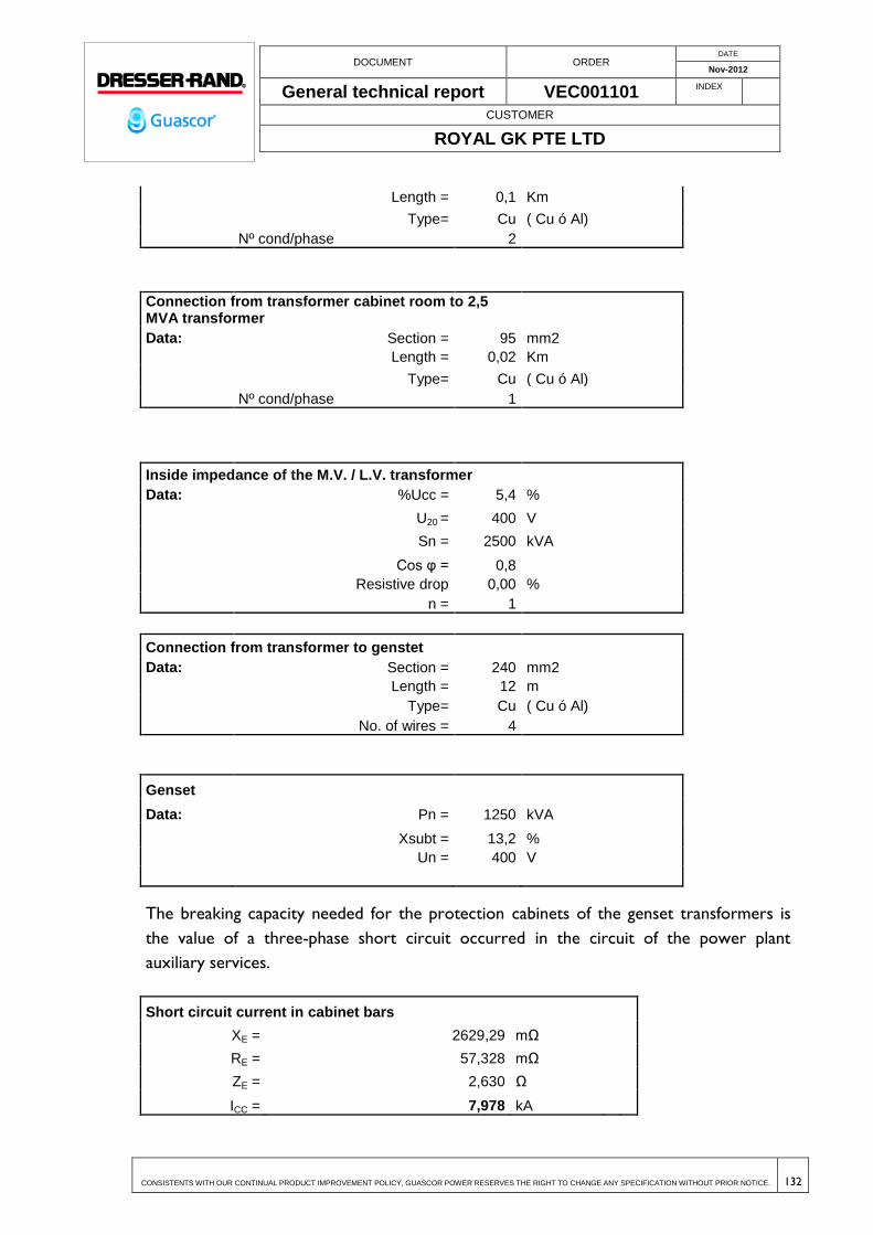
DOCUMENT ORDER DATE
Nov-2012
General technical report VEC001101 INDEX
CUSTOMER
ROYAL GK PTE LTD
CONSISTENTS WITH OUR CONTINUAL PRODUCT IMPROVEMENT POLICY, GUASCOR POWER RESERVES THE RIGHT TO CHANGE ANY SPECIFICATION WITHOUT PRIOR NOTICE. 132
Length = 0,1 Km
Type= Cu ( Cu ó Al)
Nº cond/phase 2
Connection from transformer cabinet room to 2,5 MVA transformer
Data: Section = 95 mm2
Length = 0,02 Km
Type= Cu ( Cu ó Al)
Nº cond/phase 1
Inside impedance of the M.V. / L.V. transformer
Data: %Ucc = 5,4 %
U20 = 400 V
Sn = 2500 kVA
Cos φ = 0,8
Resistive drop 0,00 %
n = 1
Connection from transformer to genstet
Data: Section = 240 mm2
Length = 12 m
Type= Cu ( Cu ó Al)
No. of wires = 4
Genset
Data: Pn = 1250 kVA
Xsubt = 13,2 %
Un = 400 V
The breaking capacity needed for the protection cabinets of the genset transformers is
the value of a three-phase short circuit occurred in the circuit of the power plant
auxiliary services.
Short circuit current in cabinet bars
XE = 2629,29 mΩ
RE = 57,328 mΩ
ZE = 2,630 Ω
ICC = 7,978 kA

DOCUMENT ORDER DATE
Nov-2012
General technical report VEC001101 INDEX
CUSTOMER
ROYAL GK PTE LTD
CONSISTENTS WITH OUR CONTINUAL PRODUCT IMPROVEMENT POLICY, GUASCOR POWER RESERVES THE RIGHT TO CHANGE ANY SPECIFICATION WITHOUT PRIOR NOTICE. 133
The short circuit current in busbars in transformer cabinet room is 8 kA.
These cabinets have a breaking capacity of 25 kA.
12.4.2 Grounding grid calculations
12.4.2.1 Maximum grounding voltage and extinguishing time
A ground mat will be provided for protection against incidental contacts. This ground mat
will be designed to ensure full operator protection and provide proper grounding,
ensuring correct operation of all protection devices.
To verify the ground mat, the following calculations have been performed for
substantiation purposes:
First, network fault current is determined. To limit the MV network fault current the
neutral of the MV isolation transformers will be grounded with a 381 resistor.
Where:
Id = network fault current - A
Rt = grounding resistance- 381
U = rated voltage - 33.000 V
Xn = grounding reactance -
2
n
2
t
d
X(R3
UI
The result obtained is:
Id = 50 A
12.4.2.2 Grounding resistance
The underground ground grid consists of a 70 mm2 naked copper wire and ground rods
drove into the ground to a depth of 0.8m.
Considering a ground resistivity of 100 . m
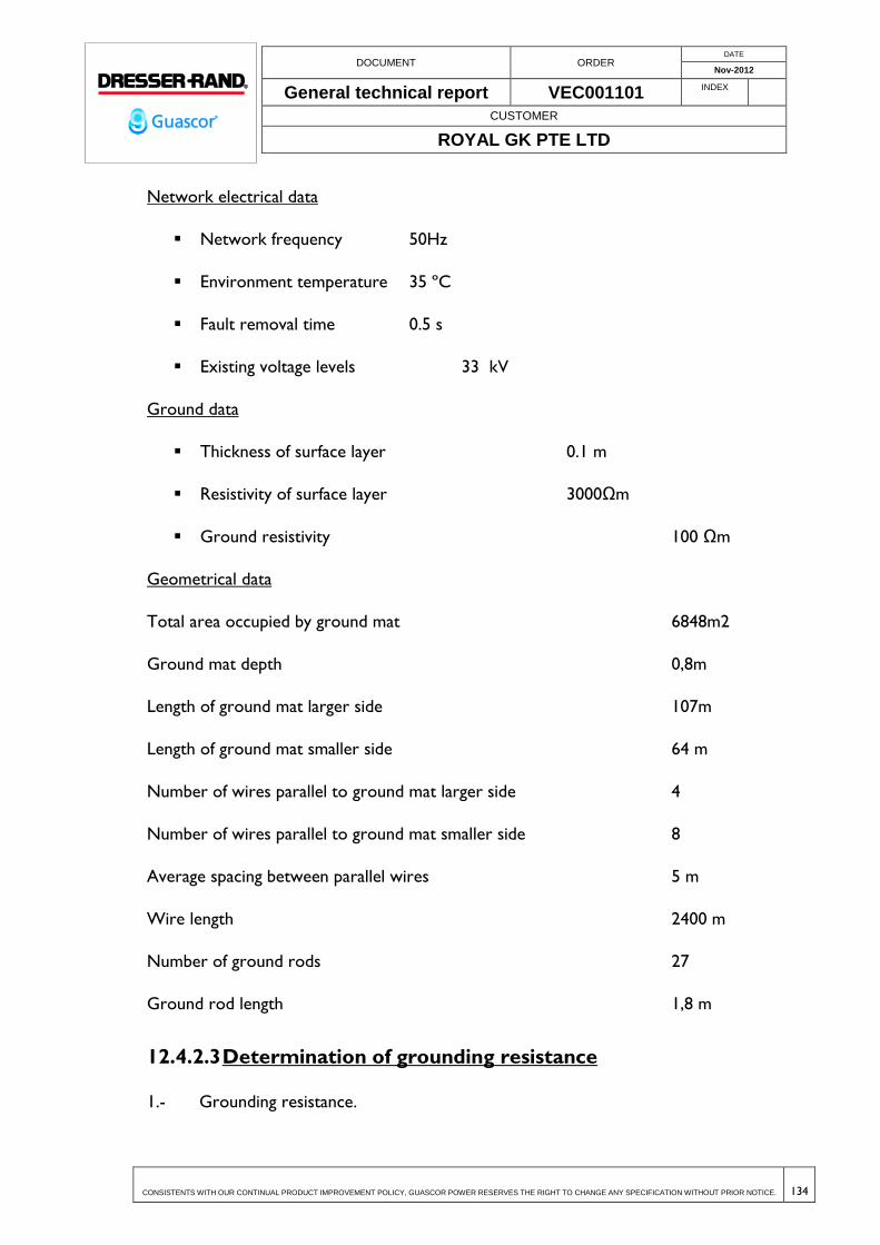
DOCUMENT ORDER DATE
Nov-2012
General technical report VEC001101 INDEX
CUSTOMER
ROYAL GK PTE LTD
CONSISTENTS WITH OUR CONTINUAL PRODUCT IMPROVEMENT POLICY, GUASCOR POWER RESERVES THE RIGHT TO CHANGE ANY SPECIFICATION WITHOUT PRIOR NOTICE. 134
Network electrical data
Network frequency 50Hz
Environment temperature 35 ºC
Fault removal time 0.5 s
Existing voltage levels 33 kV
Ground data
Thickness of surface layer 0.1 m
Resistivity of surface layer 3000Ωm
Ground resistivity 100 Ωm
Geometrical data
Total area occupied by ground mat 6848m2
Ground mat depth 0,8m
Length of ground mat larger side 107m
Length of ground mat smaller side 64 m
Number of wires parallel to ground mat larger side 4
Number of wires parallel to ground mat smaller side 8
Average spacing between parallel wires 5 m
Wire length 2400 m
Number of ground rods 27
Ground rod length 1,8 m
12.4.2.3 Determination of grounding resistance
1.- Grounding resistance.

DOCUMENT ORDER DATE
Nov-2012
General technical report VEC001101 INDEX
CUSTOMER
ROYAL GK PTE LTD
CONSISTENTS WITH OUR CONTINUAL PRODUCT IMPROVEMENT POLICY, GUASCOR POWER RESERVES THE RIGHT TO CHANGE ANY SPECIFICATION WITHOUT PRIOR NOTICE. 135
lLrRt
4
.4
Where:
= ground resistivity in ohms per meter
L = total length of underground wires
l = total length of ground rods. 34x1.8=61,2 m
r = radius of a circle equivalent to the area covered by the ground mat
698,06,482400
1004
7,464
100 x
xRt
The ground grid provided in the plant will be connected to the ground grid of existing
lighting arresters, thus improving grounding resistance.
12.4.2.4 Allowed maximums voltages to ground rules according
To verify the ground mat, the following calculations have been performed for
substantiation purposes:
The maximum permissible step and touch voltages are the following:
1) Step and touch voltages at the area in which the transformers are located:
Where:
s = concrete resistivity - 3.000 . m
= ground resistivity - 100 . m
t = opening time - 1 s
n = 1
k = 72
Vp= step voltage - V
Vc= touchvoltage - V
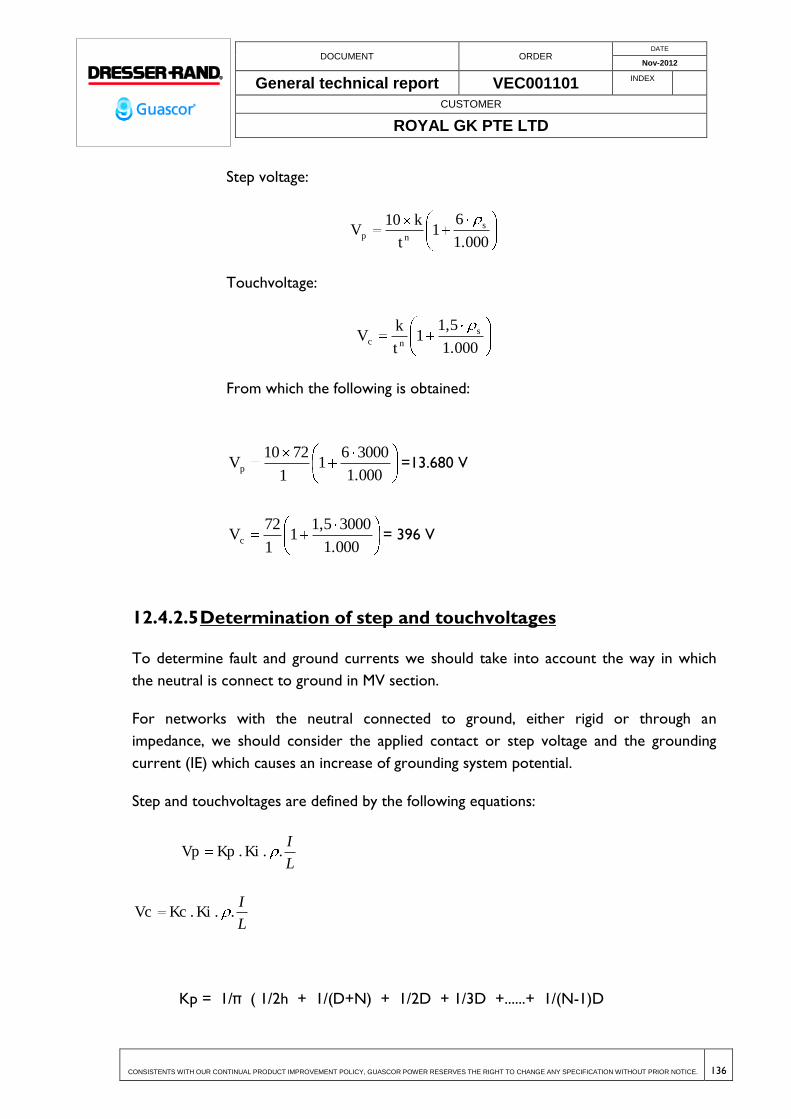
DOCUMENT ORDER DATE
Nov-2012
General technical report VEC001101 INDEX
CUSTOMER
ROYAL GK PTE LTD
CONSISTENTS WITH OUR CONTINUAL PRODUCT IMPROVEMENT POLICY, GUASCOR POWER RESERVES THE RIGHT TO CHANGE ANY SPECIFICATION WITHOUT PRIOR NOTICE. 136
Step voltage:
1.000
61
t
k10V s
np
Touchvoltage:
1.000
1,51
t
kV s
nc
From which the following is obtained:
1.000
300061
1
7210Vp =13.680 V
1.000
30001,51
1
72Vc = 396 V
12.4.2.5 Determination of step and touchvoltages
To determine fault and ground currents we should take into account the way in which
the neutral is connect to ground in MV section.
For networks with the neutral connected to ground, either rigid or through an
impedance, we should consider the applied contact or step voltage and the grounding
current (IE) which causes an increase of grounding system potential.
Step and touchvoltages are defined by the following equations:
L
I. . Ki . Kp Vp
L
I. . Ki . Kc Vc
Kp = 1/π ( 1/2h + 1/(D+N) + 1/2D + 1/3D +......+ 1/(N-1)D
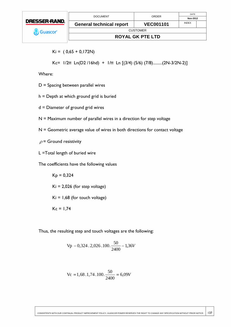
DOCUMENT ORDER DATE
Nov-2012
General technical report VEC001101 INDEX
CUSTOMER
ROYAL GK PTE LTD
CONSISTENTS WITH OUR CONTINUAL PRODUCT IMPROVEMENT POLICY, GUASCOR POWER RESERVES THE RIGHT TO CHANGE ANY SPECIFICATION WITHOUT PRIOR NOTICE. 137
Ki = ( 0,65 + 0,172N)
Kc= 1/2π Ln(D2 /16hd) + 1/π Ln [(3/4) (5/6) (7/8).........(2N-3/2N-2)]
Where:
D = Spacing between parallel wires
h = Depth at which ground grid is buried
d = Diameter of ground grid wires
N = Maximum number of parallel wires in a direction for step voltage
N = Geometric average value of wires in both directions for contact voltage
= Ground resistivity
L =Total length of buried wire
The coefficients have the following values
Kp = 0,324
Ki = 2,026 (for step voltage)
Ki = 1,68 (for touch voltage)
Kc = 1,74
Thus, the resulting step and touch voltages are the following:
V36,12400
50.100 . 2,026 . 0,324 Vp
V09,62400
50.100 . 1,74 . 1,68 Vc
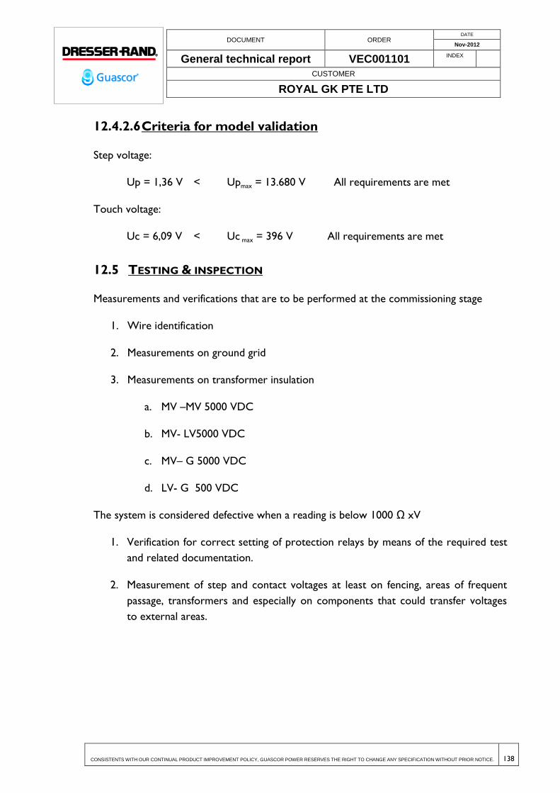
DOCUMENT ORDER DATE
Nov-2012
General technical report VEC001101 INDEX
CUSTOMER
ROYAL GK PTE LTD
CONSISTENTS WITH OUR CONTINUAL PRODUCT IMPROVEMENT POLICY, GUASCOR POWER RESERVES THE RIGHT TO CHANGE ANY SPECIFICATION WITHOUT PRIOR NOTICE. 138
12.4.2.6 Criteria for model validation
Step voltage:
Up = 1,36 V < Upmax = 13.680 V All requirements are met
Touch voltage:
Uc = 6,09 V < Uc max = 396 V All requirements are met
12.5 TESTING & INSPECTION
Measurements and verifications that are to be performed at the commissioning stage
1. Wire identification
2. Measurements on ground grid
3. Measurements on transformer insulation
a. MV –MV 5000 VDC
b. MV- LV5000 VDC
c. MV– G 5000 VDC
d. LV- G 500 VDC
The system is considered defective when a reading is below 1000 Ω xV
1. Verification for correct setting of protection relays by means of the required test
and related documentation.
2. Measurement of step and contact voltages at least on fencing, areas of frequent
passage, transformers and especially on components that could transfer voltages
to external areas.
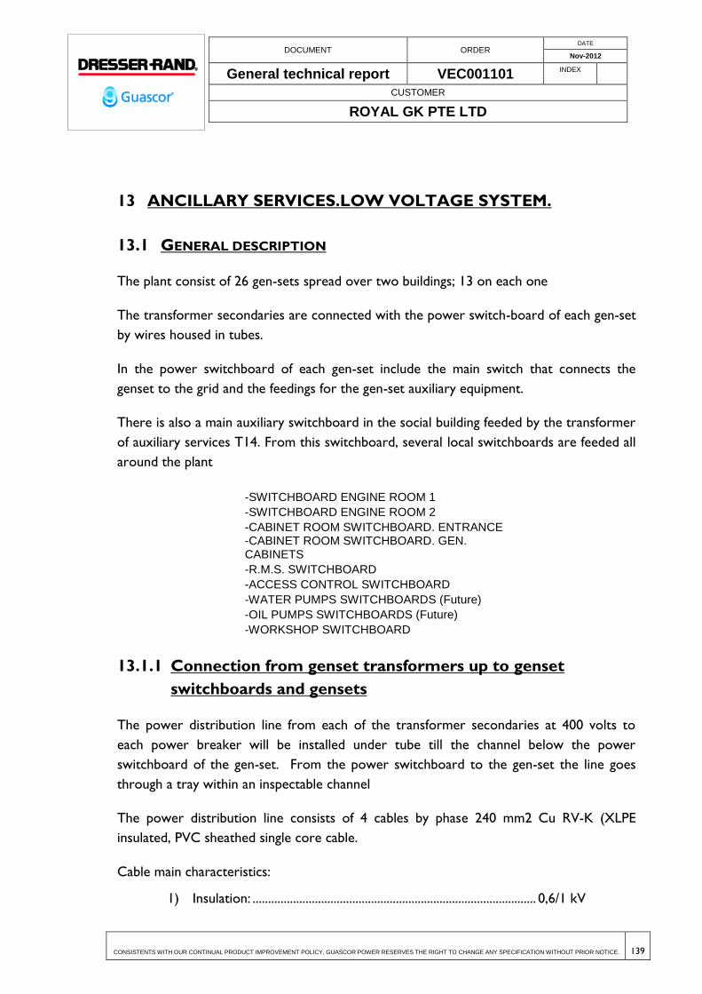
DOCUMENT ORDER DATE
Nov-2012
General technical report VEC001101 INDEX
CUSTOMER
ROYAL GK PTE LTD
CONSISTENTS WITH OUR CONTINUAL PRODUCT IMPROVEMENT POLICY, GUASCOR POWER RESERVES THE RIGHT TO CHANGE ANY SPECIFICATION WITHOUT PRIOR NOTICE. 139
13 ANCILLARY SERVICES.LOW VOLTAGE SYSTEM.
13.1 GENERAL DESCRIPTION
The plant consist of 26 gen-sets spread over two buildings; 13 on each one
The transformer secondaries are connected with the power switch-board of each gen-set
by wires housed in tubes.
In the power switchboard of each gen-set include the main switch that connects the
genset to the grid and the feedings for the gen-set auxiliary equipment.
There is also a main auxiliary switchboard in the social building feeded by the transformer
of auxiliary services T14. From this switchboard, several local switchboards are feeded all
around the plant
-SWITCHBOARD ENGINE ROOM 1
-SWITCHBOARD ENGINE ROOM 2
-CABINET ROOM SWITCHBOARD. ENTRANCE -CABINET ROOM SWITCHBOARD. GEN. CABINETS
-R.M.S. SWITCHBOARD
-ACCESS CONTROL SWITCHBOARD
-WATER PUMPS SWITCHBOARDS (Future)
-OIL PUMPS SWITCHBOARDS (Future)
-WORKSHOP SWITCHBOARD
13.1.1 Connection from genset transformers up to genset
switchboards and gensets
The power distribution line from each of the transformer secondaries at 400 volts to
each power breaker will be installed under tube till the channel below the power
switchboard of the gen-set. From the power switchboard to the gen-set the line goes
through a tray within an inspectable channel
The power distribution line consists of 4 cables by phase 240 mm2 Cu RV-K (XLPE
insulated, PVC sheathed single core cable.
Cable main characteristics:
1) Insulation: ........................................................................................... 0,6/1 kV
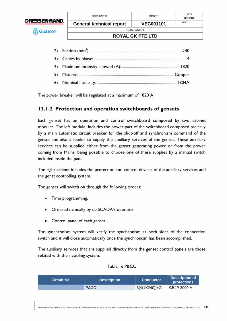
DOCUMENT ORDER DATE
Nov-2012
General technical report VEC001101 INDEX
CUSTOMER
ROYAL GK PTE LTD
CONSISTENTS WITH OUR CONTINUAL PRODUCT IMPROVEMENT POLICY, GUASCOR POWER RESERVES THE RIGHT TO CHANGE ANY SPECIFICATION WITHOUT PRIOR NOTICE. 140
2) Section (mm2): ............................................................................................ 240
3) Cables by phase: ............................................................................................ 4
4) Maximum intensity allowed (A): ......................................................... 1820
5) Material: ............................................................................................... Cooper
6) Nominal intensity. .............................................................................. 1804A
The power breaker will be regulated at a maximum of 1820 A
13.1.2 Protection and operation switchboards of gensets
Each genset has an operation and control switchboard composed by two cabinet
modules. The left module includes the power part of the switchboard composed basically
by a main automatic circuit breaker for the shut-off and synchronism command of the
genset and also a feeder to supply the auxiliary services of the genset. These auxiliary
services can be supplied either from the genset generating power or from the power
coming from Mains, being possible to choose one of these supplies by a manual switch
included inside the panel.
The right cabinet includes the protection and control devices of the auxiliary services and
the genst controlling system.
The genset will switch on through the following orders:
Time programming.
Ordered manually by de SCADA’s operator.
Control panel of each genset.
The synchronism system will verify the synchronism at both sides of the connection
switch and it will close automatically once the synchronism has been accomplished.
The auxiliary services that are supplied directly from the genset control panels are those
related with their cooling system.
Table 16.P&CC
Circuit No. Description Conductor Description of
protections
P&CC 3[4(1X240)]+G CB4P 2000 A
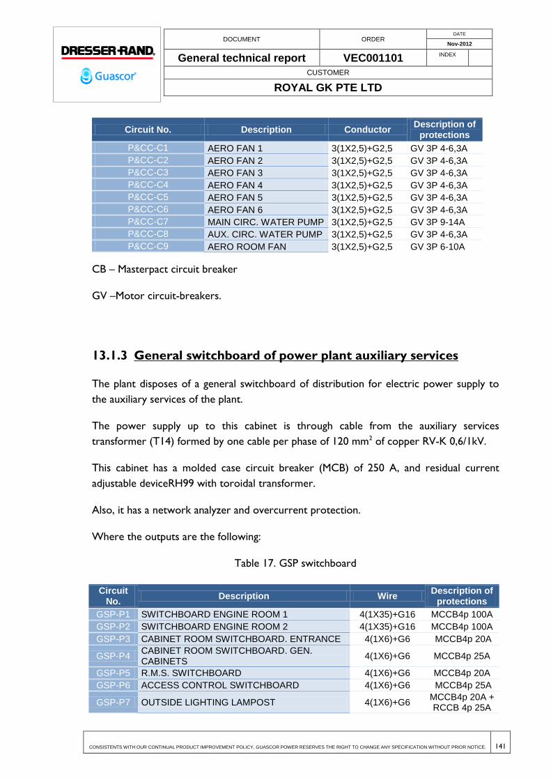
DOCUMENT ORDER DATE
Nov-2012
General technical report VEC001101 INDEX
CUSTOMER
ROYAL GK PTE LTD
CONSISTENTS WITH OUR CONTINUAL PRODUCT IMPROVEMENT POLICY, GUASCOR POWER RESERVES THE RIGHT TO CHANGE ANY SPECIFICATION WITHOUT PRIOR NOTICE. 141
Circuit No. Description Conductor Description of
protections
P&CC-C1 AERO FAN 1 3(1X2,5)+G2,5 GV 3P 4-6,3A
P&CC-C2 AERO FAN 2 3(1X2,5)+G2,5 GV 3P 4-6,3A
P&CC-C3 AERO FAN 3 3(1X2,5)+G2,5 GV 3P 4-6,3A
P&CC-C4 AERO FAN 4 3(1X2,5)+G2,5 GV 3P 4-6,3A
P&CC-C5 AERO FAN 5 3(1X2,5)+G2,5 GV 3P 4-6,3A
P&CC-C6 AERO FAN 6 3(1X2,5)+G2,5 GV 3P 4-6,3A
P&CC-C7 MAIN CIRC. WATER PUMP 3(1X2,5)+G2,5 GV 3P 9-14A
P&CC-C8 AUX. CIRC. WATER PUMP 3(1X2,5)+G2,5 GV 3P 4-6,3A
P&CC-C9 AERO ROOM FAN 3(1X2,5)+G2,5 GV 3P 6-10A
CB – Masterpact circuit breaker
GV –Motor circuit-breakers.
13.1.3 General switchboard of power plant auxiliary services
The plant disposes of a general switchboard of distribution for electric power supply to
the auxiliary services of the plant.
The power supply up to this cabinet is through cable from the auxiliary services
transformer (T14) formed by one cable per phase of 120 mm2 of copper RV-K 0,6/1kV.
This cabinet has a molded case circuit breaker (MCB) of 250 A, and residual current
adjustable deviceRH99 with toroidal transformer.
Also, it has a network analyzer and overcurrent protection.
Where the outputs are the following:
Table 17. GSP switchboard
Circuit No.
Description Wire Description of
protections
GSP-P1 SWITCHBOARD ENGINE ROOM 1 4(1X35)+G16 MCCB4p 100A
GSP-P2 SWITCHBOARD ENGINE ROOM 2 4(1X35)+G16 MCCB4p 100A
GSP-P3 CABINET ROOM SWITCHBOARD. ENTRANCE 4(1X6)+G6 MCCB4p 20A
GSP-P4 CABINET ROOM SWITCHBOARD. GEN. CABINETS
4(1X6)+G6 MCCB4p 25A
GSP-P5 R.M.S. SWITCHBOARD 4(1X6)+G6 MCCB4p 20A
GSP-P6 ACCESS CONTROL SWITCHBOARD 4(1X6)+G6 MCCB4p 25A
GSP-P7 OUTSIDE LIGHTING LAMPOST 4(1X6)+G6 MCCB4p 20A + RCCB 4p 25A

DOCUMENT ORDER DATE
Nov-2012
General technical report VEC001101 INDEX
CUSTOMER
ROYAL GK PTE LTD
CONSISTENTS WITH OUR CONTINUAL PRODUCT IMPROVEMENT POLICY, GUASCOR POWER RESERVES THE RIGHT TO CHANGE ANY SPECIFICATION WITHOUT PRIOR NOTICE. 142
Circuit No.
Description Wire Description of
protections
300mA
GSP-P8 OUTSIDE LIGHTING. ENGINE ROOM FRONTAGE
4(1X6)+G6 MCCB4p 20A + RCCB 4p 25A
300mA
GSP-P9 WATER PUMPS SWITCHBOARDS 4(1X10)+G10 MCCB 4p 40A + RCCB 4p 40A
300mA
GSP-P10 OIL PUMPS SWITCHBOARDS 4(1X10)+G10 MCCB 4p 40A + RCCB 4p 40A
300mA
GSP-P11 WORKSHOP SWITCHBOARD 4(1X10)+G10 MCCB 4p 40A
GSP-P12 RESERVE - MCCB 4p 32A
GSP-P13 POWER OUTLET. MEETING ROOM AND MANAGER OFFICE
2(1X2,5)+G2,5 MCCB 2p 16A
GSP-P14 POWER OUTLET. CONTROL ROOM. 2(1X2,5)+G2,5 MCCB 2p 16A
GSP-P15 POWER OUTLET. VARIOUS AND CONTROL ROOM
2(1X2,5)+G2,5 MCCB 2p 16A
GSP-P16 RESERVE - MCCB 2p 16A
GSP-P17 POWER OUTLET. VARIOUS DINING ROOM. 2(1X2,5)+G2,5 MCCB 2p 16A
GSP-P18 POWER OUTLET. DINING ROOM. 2(1X2,5)+G2,5 MCCB 2p 16A
GSP-P19 POWER OUTLET. DINING ROOM. 2(1X2,5)+G2,5 MCCB 2p 16A
GSP-P20 POWER OUTLET. BATHROOM. 2(1X2,5)+G2,5 MCCB 2p 16A
GSP-P21 POWER OUTLET. OUTSIDE. 2(1X2,5)+G2,5 MCCB 2p 16A
GSP-P22 RESERVE - MCCB 2p 16A
GSP-P23 UPS SCADA 2(1X2,5)+G2,5
MCCB 2p 16A + RCCB « SI » type 2p 25A
300mA
GSP-P24 FIRE-FIGHTING ALARM CONTROL 2(1X2,5)+G2,5
MCCB 2p 16A + RCCB « SI » type 2p 25A
300mA
GSP-P25 POWER OUTLET. COMPUTERS MEETING ROOM MANAGER OFFICE
2(1X2,5)+G2,5 MCCB 2p 16A
GSP-P26 POWER OUTLET. CONTROL ROOM COMPUTERS.
2(1X2,5)+G2,5 MCCB 2p 16A
GSP-P27 POWER OUTLET COMPUTERS CONTROL ROOM
2(1X2,5)+G2,5 MCCB 2p 16A
GSP-P28 POWER OUTLET COMPUTERS DINIDG ROOM 2(1X2,5)+G2,5 MCCB 2p 16A
GSP-P29 RACK PHONE CONTROL UNIT 2(1X2,5)+G2,5 MCCB 2p 16A
GSP-P30 RESERVE - MCCB 2p 16A
GSP-P31 AIR CONDITIONING SWITCHBOARD 4(1X10)+G10 MCCB 4p 32A + RCCB 4p 40A
300mA
GSP-L1 LIGHTING MEETING ROOM MANAGER OFFICE
2(1X1,5)+G1,5 MCCB 2p 10A
GSP-L2 LIGHTING CONTROL ROOM DINING ROOM 2(1X1,5)+G1,5 MCCB 2p 10A
GSP-L3 BATHROOM LIGHTING 2(1X1,5)+G1,5 MCCB 2p 10A
GSP-E1 EMERGENCY LIGHTING 2(1X1,5) MCCB 2p 10A
GSP-L4 FLUORESCENT LIGHTING TIGHT PORCH 1 2(1X1,5)+G1,5 MCCB2p 10A

DOCUMENT ORDER DATE
Nov-2012
General technical report VEC001101 INDEX
CUSTOMER
ROYAL GK PTE LTD
CONSISTENTS WITH OUR CONTINUAL PRODUCT IMPROVEMENT POLICY, GUASCOR POWER RESERVES THE RIGHT TO CHANGE ANY SPECIFICATION WITHOUT PRIOR NOTICE. 143
Circuit No.
Description Wire Description of
protections
GSP-L5 FLUORESCENT LIGHTING TIGHT PORCH 2 2(1X1,5)+G1,5 MCCB2p 10A
MCCB – Thermal-magnetic miniature circuit breaker.
RCCB= Residual current circuit breaker.
13.1.4 Engine room switchboard 1
Table 18. EN-1 switchboard
Circuit No. Description Wire Description of
protections
EN1-L1 HALL LIGHTING 2(1X2,5)+G2,5 MCCB2p 10A + SR 2p 25A
EN1-L2 HALL LIGHTING 2(1X2,5)+G2,5 MCCB2p 10A + SR 2p 25A
EN1-E1 EMERGENCY LIGHTING 2(1X1,5) MCCB2p 10A
EN1-L3 M1-M6 LIGHTING 2(1X2,5)+G2,5 MCCB2p 10A + SR 2p 25A
EN1-L4 M7-M13 LIGHTING 2(1X2,5)+G2,5 MCCB2p 10A + SR 2p 25A
EN1-L5 RESERVE - MCCB2p 10A
EN1-P1 POWER SOCKET ENGINE ROOM 4(1X16)+G16 MCCB4p 63A
EN1-P2 RESERVE - MCCB2p 16A
EN1-P3 RESERVE - MCCB2p 16A
MCCB – Thermal-magnetic miniature circuit breaker.
SR= Step-Relay.
13.1.5 Engine room switchboard 2
Table 19. EN-2 switchboard
Circuit No.
Description Wire Description of protections
EN2-L1 HALL LIGHTING 2(1X2,5)+G2,5 MCCB2p 10A + SR 2p 25A
EN2-L2 HALL LIGHTING 2(1X2,5)+G2,5 MCCB2p 10A + SR 2p 25A
EN2-E1 EMERGENCY LIGHTING 2(1X1,5) MCCB2p 10A
EN2-L3 M1-M6 LIGHTING 2(1X2,5)+G2,5 MCCB2p 10A + SR 2p 25A
EN2-L4 M7-M13 LIGHTING 2(1X2,5)+G2,5 MCCB2p 10A + SR 2p 25A
EN2-L5 RESERVE - MCCB2p 10A
EN2-P1 POWER SOCKET ENGINE ROOM 4(1X16)+G16 MCCB4p 63A
EN2-P2 RESERVE - MCCB2p 16A
EN2-P3 RESERVE - MCCB2p 16A
MCCB – Thermal-magnetic miniature circuit breaker.

DOCUMENT ORDER DATE
Nov-2012
General technical report VEC001101 INDEX
CUSTOMER
ROYAL GK PTE LTD
CONSISTENTS WITH OUR CONTINUAL PRODUCT IMPROVEMENT POLICY, GUASCOR POWER RESERVES THE RIGHT TO CHANGE ANY SPECIFICATION WITHOUT PRIOR NOTICE. 144
SR= Step-Relay.
13.1.6 Workshop switchboard
Table 20. WP switchboard
Circuit No. Description Wire Description of
protections
WP-L1 WORKSHOP LIGHTING 2(1X1,5)+G1,5 MCCB 2p 10A
WP-L2 WAREHOUSE LIGHTING 2(1X1,5)+G1,5 MCCB 2p 10A
WP-L3 OIL STORAGE LIGHTING 2(1X1,5)+G1,5 MCCB 2p 10A
WP-E1 EMERGENCY LIGHTING 2(1X1,5) MCCB 2p 10A
WP-P1 POWER OUTLET WORKSHOP 2(1X2,5)+G2,5 MCCB 2p 16A
WP-P2 POWER OUTLET WAREHOUSE 2(1X2,5)+G2,5 MCCB 2p 16A
WP-P3 POWER OUTLET WAREHOUSE 2(1X2,5)+G2,5 MCCB 2p 16A
WP-P4 RESERVE - MCCB 2p 16A
WP-P5 POWER OUTLET 3P+N+T 16A 400V 4(1X2,5)+G2,5 MCCB 4p 16A
WP-P6 RESERVE - MCCB 4p 16A
WP-P7 POWER SOCKET 4(1X10)+G10 MCCB 4p 40A
MCCB – Thermal-magnetic miniature circuit breaker.
13.1.7 Access control switchboard
Table 21. ACS switchboard
Circuit No.
Description Wire Description of
protections
ACS-L1 ACCESS CONTROL LIGHTINT EMERGENCY 2(1X1,5)+G1,5 MCCB 2p 10A
ACS-L2 RESERVE - MCCB 2p 10A
ACS-P1 POWER OUTLET 2(1X2,5)+G2,5 MCCB 2p 16A
ACS-P2 RESERVE - MCCB 2p 16A
ACS-P3 POWER OUTLET COMPUTERS 2(1X2,5)+G2,5 MCCB 2p 16A
ACS-P4 RESERVE - MCCB 2p 16A
ACS-P5 AUTOMATIC GATE SWITCHBOARD 4(1X6)+G6 MCCB 4p 10A + RCCB 4p 25A 300mA
MCCB – Thermal-magnetic miniature circuit breaker.
RCCB= Residual current circuit breaker.

DOCUMENT ORDER DATE
Nov-2012
General technical report VEC001101 INDEX
CUSTOMER
ROYAL GK PTE LTD
CONSISTENTS WITH OUR CONTINUAL PRODUCT IMPROVEMENT POLICY, GUASCOR POWER RESERVES THE RIGHT TO CHANGE ANY SPECIFICATION WITHOUT PRIOR NOTICE. 145
13.2 ENGINEERING BASIS OF DESIGN
This project was completed in compliance with the following standards:
UNE 211435 Guidance on the selection of distribution cables for rated voltages up
to and including 0,6/1 kV.
UNE 21123 Industrial cables of rated voltage 0,6/1 kV. All parts
UNE 21144 Electric cables. Calculation of the current rating. All parts
UNE 36582 Rigid steel conduit, zinc coated for use in electrical raceway
UNE-EN 50085 Cable trunking systems and cable ducting systems for electrical
installations. All parts.
UNE-EN 50086 Conduit systems for cable management. All parts.
UNE EN 60309 Plugs, socket-outlets and couplers for industrial purposes. All
parts.
UNE-EN 60423 Conduit systems for cable management - Outside diameters of
conduits for electrical installations and threads for conduits and fittings.
UNE-EN 60439 Low-voltage switchgear and controlgear assemblies. All parts.
UNE-EN 60598 Luminaires. All parts.
UNE-EN 60947 Low-voltage switchgear and controlgear. All parts.
13.3 ELECTRICAL DESIGN & DEFINITION
The estimated power for all auxiliary services in the plant is 54 kW.
The table below shows the relationship between power values and simultaneity
coefficients considered for calculation purposes.

DOCUMENT ORDER DATE
Nov-2012
General technical report VEC001101 INDEX
CUSTOMER
ROYAL GK PTE LTD
CONSISTENTS WITH OUR CONTINUAL PRODUCT IMPROVEMENT POLICY, GUASCOR POWER RESERVES THE RIGHT TO CHANGE ANY SPECIFICATION WITHOUT PRIOR NOTICE. 146
Table 22. Electric power calculations
Circuit No. Description Load Pn
(W)
Simultaneity coefficient
Simult.
Pn Switchboard(W)
GSP 53792,498 100,00% 53792
GSP-P1 SWITCHBOARD ENGINE ROOM 1 9760,56 90,00% 8785
GSP-P2 SWITCHBOARD ENGINE ROOM 2 9767,76 90,00% 8791
GSP-P3 CABINET ROOM SWITCHBOARD. ENTRANCE 2500 90,00% 2250
GSP-P4 CABINET ROOM SWITCHBOARD. GEN. CABINETS 4000 90,00% 3600
GSP-P5 R.M.S. SWITCHBOARD 2500 90,00% 2250
GSP-P6 ACCESS CONTROL SWITCHBOARD 1059,4 90,00% 953
GSP-P7 OUTSIDE LIGHTING LAMPOST 4500 90,00% 4050
GSP-P8 OUTSIDE LIGHTING. ENGINE ROOM FRONTAGE 3600 90,00% 3240
GSP-P9 WATER PUMPS SWITCHBOARDS 0 90,00% 0
GSP-P10 OIL PUMPS SWITCHBOARDS 0 90,00% 0
GSP-P11 WORKSHOP SWITCHBOARD 7470,3 90,00% 6723
GSP-P12 RESERVE 0 90,00% 0
GSP-P13 POWER OUTLET. MEETING ROOM AND MANAGER OFFICE 3680 20,00% 736
GSP-P14 POWER OUTLET. CONTROL ROOM. 3680 20,00% 736
GSP-P15 POWER OUTLET. VARIOUS AND CONTROL ROOM 3680 20,00% 736
GSP-P16 RESERVE 0 70,00% 0
GSP-P17 POWER OUTLET. VARIOUS DINING ROOM. 3680 20,00% 736
GSP-P18 POWER OUTLET. DINING ROOM. 3680 20,00% 736
GSP-P19 POWER OUTLET. DINING ROOM. 3680 20,00% 736
GSP-P20 POWER OUTLET. BATHROOM. 3680 20,00% 736
GSP-P21 POWER OUTLET. OUTSIDE. 3680 20,00% 736
GSP-P22 RESERVE 0 20,00% 0
GSP-P23 UPS SCADA 1000 50,00% 500
GSP-P24 FIRE-FIGHTING ALARM CONTROL 300 100,00% 300
GSP-P25 POWER OUTLET. COMPUTERS MEETING ROOM MANAGER OFFICE 3680 20,00% 736
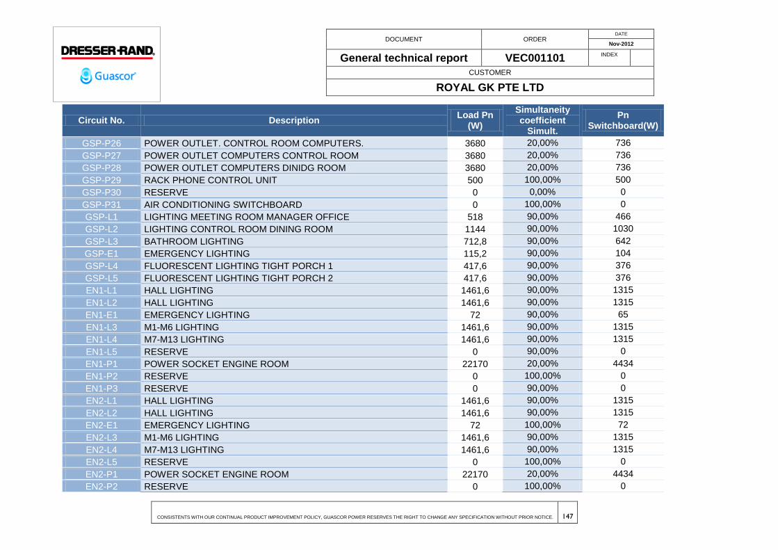
DOCUMENT ORDER DATE
Nov-2012
General technical report VEC001101 INDEX
CUSTOMER
ROYAL GK PTE LTD
CONSISTENTS WITH OUR CONTINUAL PRODUCT IMPROVEMENT POLICY, GUASCOR POWER RESERVES THE RIGHT TO CHANGE ANY SPECIFICATION WITHOUT PRIOR NOTICE. 147
Circuit No. Description Load Pn
(W)
Simultaneity coefficient
Simult.
Pn Switchboard(W)
GSP-P26 POWER OUTLET. CONTROL ROOM COMPUTERS. 3680 20,00% 736
GSP-P27 POWER OUTLET COMPUTERS CONTROL ROOM 3680 20,00% 736
GSP-P28 POWER OUTLET COMPUTERS DINIDG ROOM 3680 20,00% 736
GSP-P29 RACK PHONE CONTROL UNIT 500 100,00% 500
GSP-P30 RESERVE 0 0,00% 0
GSP-P31 AIR CONDITIONING SWITCHBOARD 0 100,00% 0
GSP-L1 LIGHTING MEETING ROOM MANAGER OFFICE 518 90,00% 466
GSP-L2 LIGHTING CONTROL ROOM DINING ROOM 1144 90,00% 1030
GSP-L3 BATHROOM LIGHTING 712,8 90,00% 642
GSP-E1 EMERGENCY LIGHTING 115,2 90,00% 104
GSP-L4 FLUORESCENT LIGHTING TIGHT PORCH 1 417,6 90,00% 376
GSP-L5 FLUORESCENT LIGHTING TIGHT PORCH 2 417,6 90,00% 376
EN1-L1 HALL LIGHTING 1461,6 90,00% 1315
EN1-L2 HALL LIGHTING 1461,6 90,00% 1315
EN1-E1 EMERGENCY LIGHTING 72 90,00% 65
EN1-L3 M1-M6 LIGHTING 1461,6 90,00% 1315
EN1-L4 M7-M13 LIGHTING 1461,6 90,00% 1315
EN1-L5 RESERVE 0 90,00% 0
EN1-P1 POWER SOCKET ENGINE ROOM 22170 20,00% 4434
EN1-P2 RESERVE 0 100,00% 0
EN1-P3 RESERVE 0 90,00% 0
EN2-L1 HALL LIGHTING 1461,6 90,00% 1315
EN2-L2 HALL LIGHTING 1461,6 90,00% 1315
EN2-E1 EMERGENCY LIGHTING 72 100,00% 72
EN2-L3 M1-M6 LIGHTING 1461,6 90,00% 1315
EN2-L4 M7-M13 LIGHTING 1461,6 90,00% 1315
EN2-L5 RESERVE 0 100,00% 0
EN2-P1 POWER SOCKET ENGINE ROOM 22170 20,00% 4434
EN2-P2 RESERVE 0 100,00% 0

DOCUMENT ORDER DATE
Nov-2012
General technical report VEC001101 INDEX
CUSTOMER
ROYAL GK PTE LTD
CONSISTENTS WITH OUR CONTINUAL PRODUCT IMPROVEMENT POLICY, GUASCOR POWER RESERVES THE RIGHT TO CHANGE ANY SPECIFICATION WITHOUT PRIOR NOTICE. 148
Circuit No. Description Load Pn
(W)
Simultaneity coefficient
Simult.
Pn Switchboard(W)
EN2-P3 RESERVE 0 90,00% 0
WP-L1 WORKSHOP LIGHTING 417,6 90,00% 376
WP-L2 WAREHOUSE LIGHTING 1252,8 90,00% 1128
WP-L3 OIL STORAGE LIGHTING 417,6 90,00% 376
WP-E1 EMERGENCY LIGHTING 57,6 100,00% 58
WP-P1 POWER OUTLET WORKSHOP 3680 20,00% 736
WP-P2 POWER OUTLET WAREHOUSE 3680 20,00% 736
WP-P3 POWER OUTLET WAREHOUSE 3680 20,00% 736
WP-P4 RESERVE 0 100,00% 0
WP-P5 POWER OUTLET 3P+N+T 16A 400V 11085 10,00% 1109
WP-P6 RESERVE 0 100,00% 0
WP-P7 POWER SOCKET 22170 10,00% 2217
ACS-L1 ACCESS CONTROL LIGHTINT EMERGENCY 306 90,00% 275
ACS-L2 RESERVE 0 100,00% 0
ACS-P1 POWER OUTLET 3680 20,00% 736
ACS-P2 RESERVE 0 90,00% 0
ACS-P3 POWER OUTLET COMPUTERS 3680 20,00% 48
ACS-P4 RESERVE 0 90,00% 0
ACS-P5 AUTOMATIC GATE SWITCHBOARD 0 100,00% 0
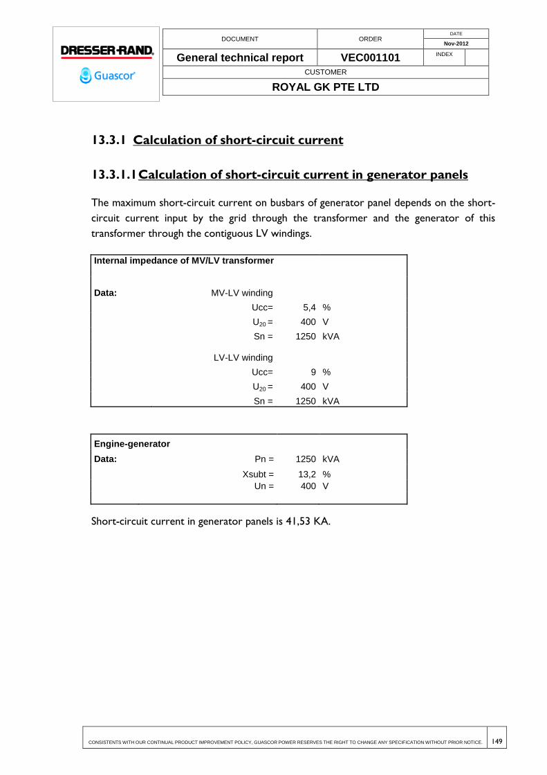
DOCUMENT ORDER DATE
Nov-2012
General technical report VEC001101 INDEX
CUSTOMER
ROYAL GK PTE LTD
CONSISTENTS WITH OUR CONTINUAL PRODUCT IMPROVEMENT POLICY, GUASCOR POWER RESERVES THE RIGHT TO CHANGE ANY SPECIFICATION WITHOUT PRIOR NOTICE. 149
13.3.1 Calculation of short-circuit current
13.3.1.1 Calculation of short-circuit current in generator panels
The maximum short-circuit current on busbars of generator panel depends on the short-
circuit current input by the grid through the transformer and the generator of this
transformer through the contiguous LV windings.
Internal impedance of MV/LV transformer
Data:
MV-LV winding
Ucc= 5,4 %
U20 = 400 V
Sn = 1250 kVA
LV-LV winding
Ucc= 9 %
U20 = 400 V
Sn = 1250 kVA
Engine-generator
Data: Pn = 1250 kVA
Xsubt = 13,2 %
Un = 400 V
Short-circuit current in generator panels is 41,53 KA.
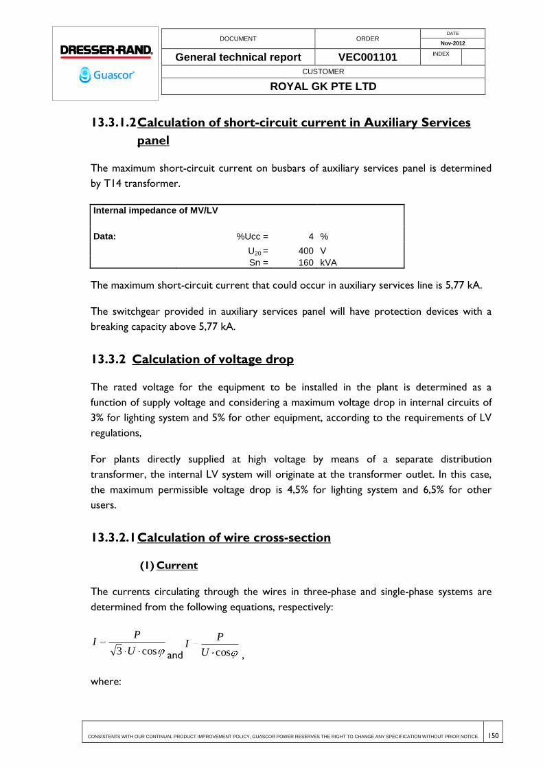
DOCUMENT ORDER DATE
Nov-2012
General technical report VEC001101 INDEX
CUSTOMER
ROYAL GK PTE LTD
CONSISTENTS WITH OUR CONTINUAL PRODUCT IMPROVEMENT POLICY, GUASCOR POWER RESERVES THE RIGHT TO CHANGE ANY SPECIFICATION WITHOUT PRIOR NOTICE. 150
13.3.1.2 Calculation of short-circuit current in Auxiliary Services
panel
The maximum short-circuit current on busbars of auxiliary services panel is determined
by T14 transformer.
Internal impedance of MV/LV
Data: %Ucc = 4 %
U20 = 400 V
Sn = 160 kVA
The maximum short-circuit current that could occur in auxiliary services line is 5,77 kA.
The switchgear provided in auxiliary services panel will have protection devices with a
breaking capacity above 5,77 kA.
13.3.2 Calculation of voltage drop
The rated voltage for the equipment to be installed in the plant is determined as a
function of supply voltage and considering a maximum voltage drop in internal circuits of
3% for lighting system and 5% for other equipment, according to the requirements of LV
regulations,
For plants directly supplied at high voltage by means of a separate distribution
transformer, the internal LV system will originate at the transformer outlet. In this case,
the maximum permissible voltage drop is 4,5% for lighting system and 6,5% for other
users.
13.3.2.1 Calculation of wire cross-section
(1) Current
The currents circulating through the wires in three-phase and single-phase systems are
determined from the following equations, respectively:
and ,
where:
cos3 U
PI
cosU
PI

DOCUMENT ORDER DATE
Nov-2012
General technical report VEC001101 INDEX
CUSTOMER
ROYAL GK PTE LTD
CONSISTENTS WITH OUR CONTINUAL PRODUCT IMPROVEMENT POLICY, GUASCOR POWER RESERVES THE RIGHT TO CHANGE ANY SPECIFICATION WITHOUT PRIOR NOTICE. 151
I: current (A)
P: active power (W)
U: rated power (V)
cos : power factor
(2) Voltage drop
Voltage drop throughout the wires in three-phase and single-phase systems is determined
from the following equations, respectively:
and ,
where:
e: compound voltage drop (V)
L: wire length (m)
I: current in each phase or neutral (A)
cos : power factor
: wire electrical conductivity (m/ mm2)
S: wire cross-section (mm2)
The percentile value of voltage drop is:
.
We have considered an electrical conductivity of 56 and 35 m/ for Cu and Al
respectively.
S
ILe
cos3
S
ILe
cos2
)(
)(100(%)
VU
Vee
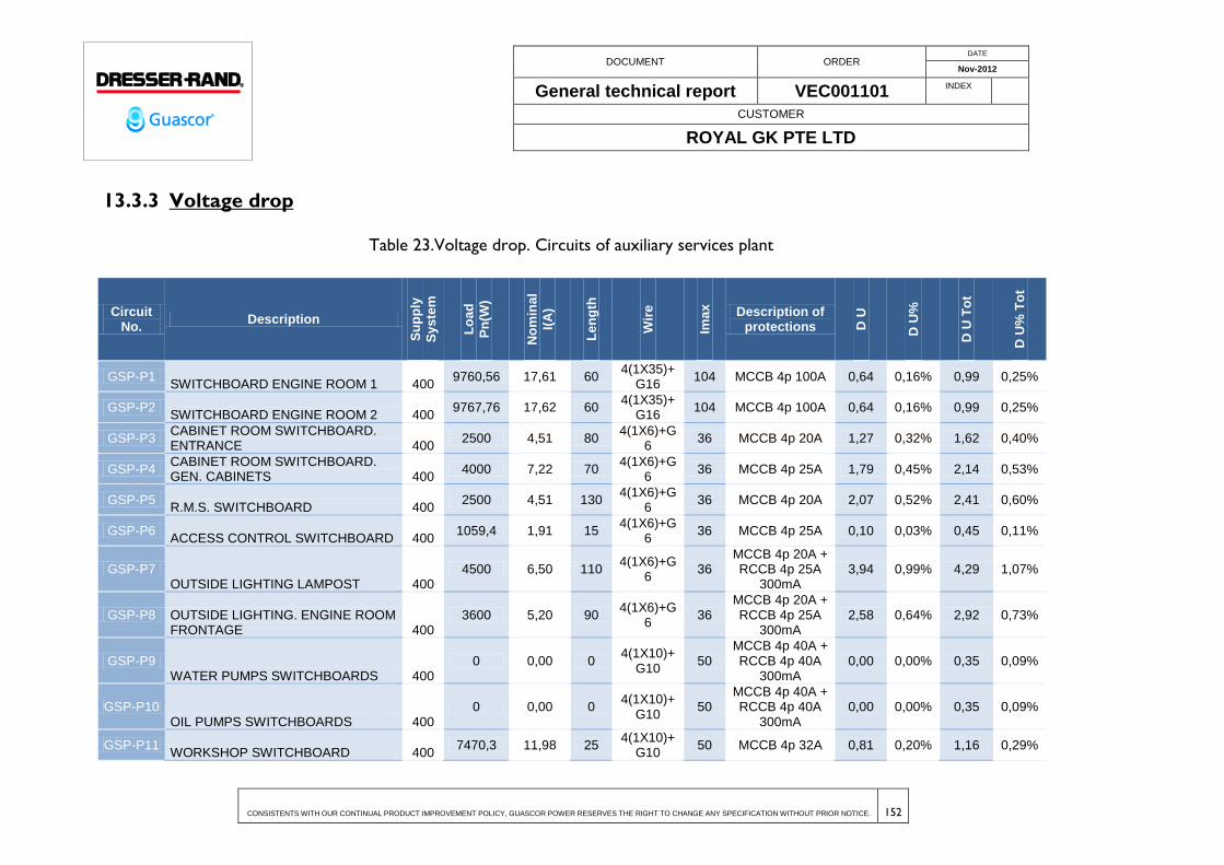
DOCUMENT ORDER DATE
Nov-2012
General technical report VEC001101 INDEX
CUSTOMER
ROYAL GK PTE LTD
CONSISTENTS WITH OUR CONTINUAL PRODUCT IMPROVEMENT POLICY, GUASCOR POWER RESERVES THE RIGHT TO CHANGE ANY SPECIFICATION WITHOUT PRIOR NOTICE. 152
13.3.3 Voltage drop
Table 23.Voltage drop. Circuits of auxiliary services plant
Circuit No.
Description
Su
pp
ly
Sy
ste
m
Lo
ad
Pn
(W)
No
min
al
I(A
)
Le
ng
th
Wir
e
Ima
x
Description of protections D
U
D U
%
D U
To
t
D U
% T
ot
GSP-P1 SWITCHBOARD ENGINE ROOM 1 400
9760,56 17,61 60 4(1X35)+
G16 104 MCCB 4p 100A 0,64 0,16% 0,99 0,25%
GSP-P2 SWITCHBOARD ENGINE ROOM 2 400
9767,76 17,62 60 4(1X35)+
G16 104 MCCB 4p 100A 0,64 0,16% 0,99 0,25%
GSP-P3 CABINET ROOM SWITCHBOARD. ENTRANCE 400
2500 4,51 80 4(1X6)+G
6 36 MCCB 4p 20A 1,27 0,32% 1,62 0,40%
GSP-P4 CABINET ROOM SWITCHBOARD. GEN. CABINETS 400
4000 7,22 70 4(1X6)+G
6 36 MCCB 4p 25A 1,79 0,45% 2,14 0,53%
GSP-P5 R.M.S. SWITCHBOARD 400
2500 4,51 130 4(1X6)+G
6 36 MCCB 4p 20A 2,07 0,52% 2,41 0,60%
GSP-P6 ACCESS CONTROL SWITCHBOARD 400
1059,4 1,91 15 4(1X6)+G
6 36 MCCB 4p 25A 0,10 0,03% 0,45 0,11%
GSP-P7 OUTSIDE LIGHTING LAMPOST 400
4500 6,50 110 4(1X6)+G
6 36
MCCB 4p 20A + RCCB 4p 25A
300mA 3,94 0,99% 4,29 1,07%
GSP-P8 OUTSIDE LIGHTING. ENGINE ROOM FRONTAGE 400
3600 5,20 90 4(1X6)+G
6 36
MCCB 4p 20A + RCCB 4p 25A
300mA 2,58 0,64% 2,92 0,73%
GSP-P9 WATER PUMPS SWITCHBOARDS 400
0 0,00 0 4(1X10)+
G10 50
MCCB 4p 40A + RCCB 4p 40A
300mA 0,00 0,00% 0,35 0,09%
GSP-P10 OIL PUMPS SWITCHBOARDS 400
0 0,00 0 4(1X10)+
G10 50
MCCB 4p 40A + RCCB 4p 40A
300mA 0,00 0,00% 0,35 0,09%
GSP-P11 WORKSHOP SWITCHBOARD 400
7470,3 11,98 25 4(1X10)+
G10 50 MCCB 4p 32A 0,81 0,20% 1,16 0,29%

DOCUMENT ORDER DATE
Nov-2012
General technical report VEC001101 INDEX
CUSTOMER
ROYAL GK PTE LTD
CONSISTENTS WITH OUR CONTINUAL PRODUCT IMPROVEMENT POLICY, GUASCOR POWER RESERVES THE RIGHT TO CHANGE ANY SPECIFICATION WITHOUT PRIOR NOTICE. 153
Circuit No.
Description
Su
pp
ly
Sy
ste
m
Lo
ad
Pn
(W)
No
min
al
I(A
)
Le
ng
th
Wir
e
Ima
x
Description of protections D
U
D U
%
D U
To
t
D U
% T
ot
GSP-P12 RESERVE 400 0 Error 0 - 0 MCCB 4p 32A - - - -
GSP-P13 POWER OUTLET. MEETING ROOM AND MANAGER OFFICE 230
3680 16,00 28 2(1X2,5)+
G2,5 22 MCCB 2p 16A 7,48 3,25% 7,83 3,40%
GSP-P14 POWER OUTLET. CONTROL ROOM. 230
3680 16,00 20 2(1X2,5)+
G2,5 22 MCCB 2p 16A 5,34 2,32% 5,69 2,47%
GSP-P15 POWER OUTLET. VARIOUS AND CONTROL ROOM 230
3680 16,00 20 2(1X2,5)+
G2,5 22 MCCB 2p 16A 5,34 2,32% 5,69 2,47%
GSP-P16 RESERVE 230 0 Error 0 - 0 MCCB 2p 16A - - - -
GSP-P17 POWER OUTLET. VARIOUS DINING ROOM. 230
3680 16,00 28 2(1X2,5)+
G2,5 22 MCCB 2p 16A 7,48 3,25% 7,83 3,40%
GSP-P18 POWER OUTLET. DINING ROOM. 230
3680 16,00 26 2(1X2,5)+
G2,5 22 MCCB 2p 16A 6,95 3,02% 7,29 3,17%
GSP-P19 POWER OUTLET. DINING ROOM. 230
3680 16,00 28 2(1X2,5)+
G2,5 22 MCCB 2p 16A 7,48 3,25% 7,83 3,40%
GSP-P20 POWER OUTLET. BATHROOM. 230
3680 16,00 35 2(1X2,5)+
G2,5 22 MCCB 2p 16A 9,35 4,07% 9,70 4,22%
GSP-P21 POWER OUTLET. OUTSIDE. 230
3680 16,00 30 2(1X2,5)+
G2,5 22 MCCB 2p 16A 8,01 3,48% 8,36 3,64%
GSP-P22 RESERVE 230 0
0 - 0 MCCB 2p 16A - - - -
GSP-P23 UPS SCADA 230
1000 4,35 8 2(1X2,5)+
G2,5 22
MCCB 2p 16A + RCCB 2p 25A
300mA 0,53 0,23% 0,88 0,38%
GSP-P24 FIRE-FIGHTING ALARM CONTROL 230
300 1,30 5 2(1X2,5)+
G2,5 22
MCCB 2p 16A + RCCB 2p 25A
300mA 0,10 0,04% 0,45 0,19%
GSP-P25 POWER OUTLET. COMPUTERS MEETING ROOM MANAGER OFFICE 230
3680 16,00 20 2(1X2,5)+
G2,5 22 MCCB 2p 16A 5,34 2,32% 5,69 2,47%
GSP-P26 POWER OUTLET. CONTROL ROOM COMPUTERS. 230
3680 16,00 15 2(1X2,5)+
G2,5 22 MCCB 2p 16A 4,01 1,74% 4,36 1,89%
GSP-P27 POWER OUTLET COMPUTERS CONTROL ROOM 230
3680 16,00 15 2(1X2,5)+
G2,5 22 MCCB 2p 16A 4,01 1,74% 4,36 1,89%
GSP-P28 POWER OUTLET COMPUTERS DINIDG ROOM 230
3680 16,00 20 2(1X2,5)+
G2,5 22 MCCB 2p 16A 5,34 2,32% 5,69 2,47%
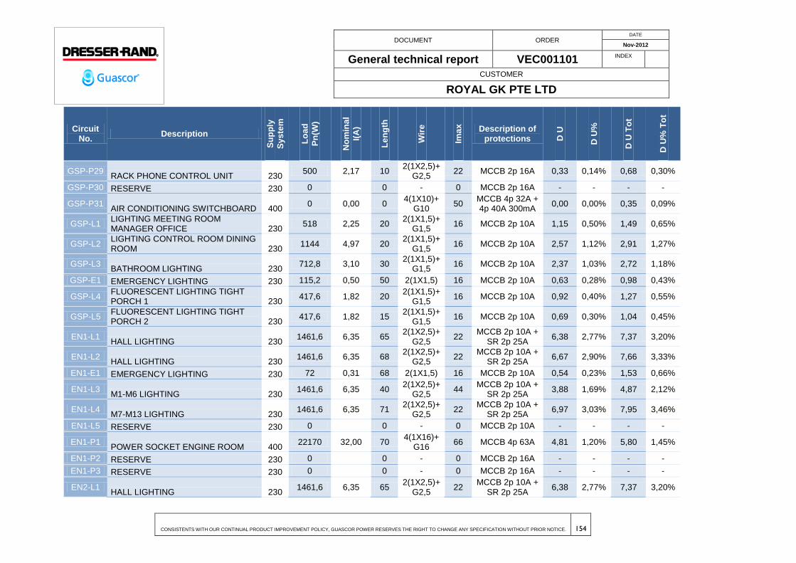
DOCUMENT ORDER DATE
Nov-2012
General technical report VEC001101 INDEX
CUSTOMER
ROYAL GK PTE LTD
CONSISTENTS WITH OUR CONTINUAL PRODUCT IMPROVEMENT POLICY, GUASCOR POWER RESERVES THE RIGHT TO CHANGE ANY SPECIFICATION WITHOUT PRIOR NOTICE. 154
Circuit No.
Description
Su
pp
ly
Sy
ste
m
Lo
ad
Pn
(W)
No
min
al
I(A
)
Le
ng
th
Wir
e
Ima
x
Description of protections D
U
D U
%
D U
To
t
D U
% T
ot
GSP-P29 RACK PHONE CONTROL UNIT 230
500 2,17 10 2(1X2,5)+
G2,5 22 MCCB 2p 16A 0,33 0,14% 0,68 0,30%
GSP-P30 RESERVE 230 0
0 - 0 MCCB 2p 16A - - - -
GSP-P31 AIR CONDITIONING SWITCHBOARD 400
0 0,00 0 4(1X10)+
G10 50
MCCB 4p 32A + 4p 40A 300mA
0,00 0,00% 0,35 0,09%
GSP-L1 LIGHTING MEETING ROOM MANAGER OFFICE 230
518 2,25 20 2(1X1,5)+
G1,5 16 MCCB 2p 10A 1,15 0,50% 1,49 0,65%
GSP-L2 LIGHTING CONTROL ROOM DINING ROOM 230
1144 4,97 20 2(1X1,5)+
G1,5 16 MCCB 2p 10A 2,57 1,12% 2,91 1,27%
GSP-L3 BATHROOM LIGHTING 230
712,8 3,10 30 2(1X1,5)+
G1,5 16 MCCB 2p 10A 2,37 1,03% 2,72 1,18%
GSP-E1 EMERGENCY LIGHTING 230 115,2 0,50 50 2(1X1,5) 16 MCCB 2p 10A 0,63 0,28% 0,98 0,43%
GSP-L4 FLUORESCENT LIGHTING TIGHT PORCH 1 230
417,6 1,82 20 2(1X1,5)+
G1,5 16 MCCB 2p 10A 0,92 0,40% 1,27 0,55%
GSP-L5 FLUORESCENT LIGHTING TIGHT PORCH 2 230
417,6 1,82 15 2(1X1,5)+
G1,5 16 MCCB 2p 10A 0,69 0,30% 1,04 0,45%
EN1-L1 HALL LIGHTING 230
1461,6 6,35 65 2(1X2,5)+
G2,5 22
MCCB 2p 10A + SR 2p 25A
6,38 2,77% 7,37 3,20%
EN1-L2 HALL LIGHTING 230
1461,6 6,35 68 2(1X2,5)+
G2,5 22
MCCB 2p 10A + SR 2p 25A
6,67 2,90% 7,66 3,33%
EN1-E1 EMERGENCY LIGHTING 230 72 0,31 68 2(1X1,5) 16 MCCB 2p 10A 0,54 0,23% 1,53 0,66%
EN1-L3 M1-M6 LIGHTING 230
1461,6 6,35 40 2(1X2,5)+
G2,5 44
MCCB 2p 10A + SR 2p 25A
3,88 1,69% 4,87 2,12%
EN1-L4 M7-M13 LIGHTING 230
1461,6 6,35 71 2(1X2,5)+
G2,5 22
MCCB 2p 10A + SR 2p 25A
6,97 3,03% 7,95 3,46%
EN1-L5 RESERVE 230 0
0 - 0 MCCB 2p 10A - - - -
EN1-P1 POWER SOCKET ENGINE ROOM 400
22170 32,00 70 4(1X16)+
G16 66 MCCB 4p 63A 4,81 1,20% 5,80 1,45%
EN1-P2 RESERVE 230 0
0 - 0 MCCB 2p 16A - - - -
EN1-P3 RESERVE 230 0
0 - 0 MCCB 2p 16A - - - -
EN2-L1 HALL LIGHTING 230
1461,6 6,35 65 2(1X2,5)+
G2,5 22
MCCB 2p 10A + SR 2p 25A
6,38 2,77% 7,37 3,20%
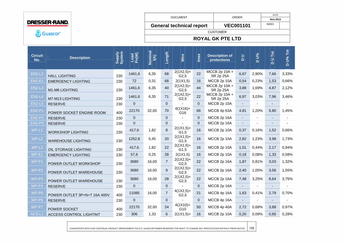
DOCUMENT ORDER DATE
Nov-2012
General technical report VEC001101 INDEX
CUSTOMER
ROYAL GK PTE LTD
CONSISTENTS WITH OUR CONTINUAL PRODUCT IMPROVEMENT POLICY, GUASCOR POWER RESERVES THE RIGHT TO CHANGE ANY SPECIFICATION WITHOUT PRIOR NOTICE. 155
Circuit No.
Description
Su
pp
ly
Sy
ste
m
Lo
ad
Pn
(W)
No
min
al
I(A
)
Le
ng
th
Wir
e
Ima
x
Description of protections D
U
D U
%
D U
To
t
D U
% T
ot
EN2-L2 HALL LIGHTING 230
1461,6 6,35 68 2(1X2,5)+
G2,5 22
MCCB 2p 10A + SR 2p 25A
6,67 2,90% 7,66 3,33%
EN2-E1 EMERGENCY LIGHTING 230 72 0,31 68 2(1X1,5) 16 MCCB 2p 10A 0,54 0,23% 1,53 0,66%
EN2-L3 M1-M6 LIGHTING 230
1461,6 6,35 40 2(1X2,5)+
G2,5 44
MCCB 2p 10A + SR 2p 25A
3,88 1,69% 4,87 2,12%
EN2-L4 M7-M13 LIGHTING 230
1461,6 6,35 71 2(1X2,5)+
G2,5 22
MCCB 2p 10A + SR 2p 25A
6,97 3,03% 7,96 3,46%
EN2-L5 RESERVE 230 0
0 - 0 MCCB 2p 10A - - - -
EN2-P1 POWER SOCKET ENGINE ROOM 400
22170 32,00 70 4(1X16)+
G16 66 MCCB 4p 63A 4,81 1,20% 5,80 1,45%
EN2-P2 RESERVE 230 0
0 - 0 MCCB 2p 16A - - - -
EN2-P3 RESERVE 230 0
0 - 0 MCCB 2p 16A - - - -
WP-L1 WORKSHOP LIGHTING 230
417,6 1,82 8 2(1X1,5)+
G1,5 16 MCCB 2p 10A 0,37 0,16% 1,52 0,66%
WP-L2 WAREHOUSE LIGHTING 230
1252,8 5,45 20 2(1X1,5)+
G1,5 16 MCCB 2p 10A 2,82 1,23% 3,98 1,73%
WP-L3 OIL STORAGE LIGHTING 230
417,6 1,82 22 2(1X1,5)+
G1,5 16 MCCB 2p 10A 1,01 0,44% 2,17 0,94%
WP-E1 EMERGENCY LIGHTING 230 57,6 0,25 28 2(1X1,5) 16 MCCB 2p 10A 0,18 0,08% 1,33 0,58%
WP-P1 POWER OUTLET WORKSHOP 230
3680 16,00 7 2(1X2,5)+
G2,5 22 MCCB 2p 16A 1,87 0,81% 3,03 1,32%
WP-P2 POWER OUTLET WAREHOUSE 230
3680 16,00 9 2(1X2,5)+
G2,5 22 MCCB 2p 16A 2,40 1,05% 3,56 1,55%
WP-P3 POWER OUTLET WAREHOUSE 230
3680 16,00 28 2(1X2,5)+
G2,5 22 MCCB 2p 16A 7,48 3,25% 8,64 3,75%
WP-P4 RESERVE 230 0
0 - 0 MCCB 2p 16A - - - -
WP-P5 POWER OUTLET 3P+N+T 16A 400V 400
11085 16,00 7 4(1X2,5)+
G2,5 21 MCCB 4p 16A 1,63 0,41% 2,79 0,70%
WP-P6 RESERVE 230 0
0 - 0 MCCB 4p 16A - - - -
WP-P7 POWER SOCKET 400
22170 32,00 24 4(1X10)+
G10 50 MCCB 4p 40A 2,72 0,68% 3,88 0,97%
ACS-L1 ACCESS CONTROL LIGHTINT 230 306 1,33 6 2(1X1,5)+ 16 MCCB 2p 10A 0,20 0,09% 0,65 0,28%
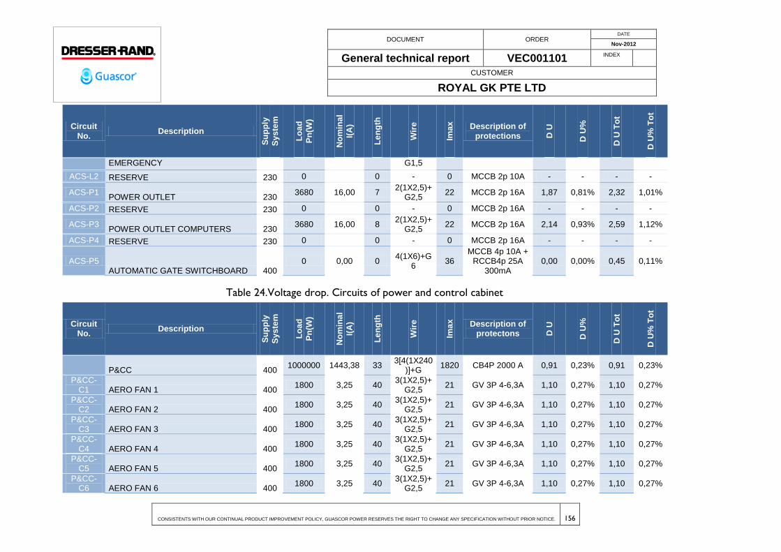
DOCUMENT ORDER DATE
Nov-2012
General technical report VEC001101 INDEX
CUSTOMER
ROYAL GK PTE LTD
CONSISTENTS WITH OUR CONTINUAL PRODUCT IMPROVEMENT POLICY, GUASCOR POWER RESERVES THE RIGHT TO CHANGE ANY SPECIFICATION WITHOUT PRIOR NOTICE. 156
Circuit No.
Description
Su
pp
ly
Sy
ste
m
Lo
ad
Pn
(W)
No
min
al
I(A
)
Le
ng
th
Wir
e
Ima
x
Description of protections D
U
D U
%
D U
To
t
D U
% T
ot
EMERGENCY G1,5
ACS-L2 RESERVE 230 0
0 - 0 MCCB 2p 10A - - - -
ACS-P1 POWER OUTLET 230
3680 16,00 7 2(1X2,5)+
G2,5 22 MCCB 2p 16A 1,87 0,81% 2,32 1,01%
ACS-P2 RESERVE 230 0
0 - 0 MCCB 2p 16A - - - -
ACS-P3 POWER OUTLET COMPUTERS 230
3680 16,00 8 2(1X2,5)+
G2,5 22 MCCB 2p 16A 2,14 0,93% 2,59 1,12%
ACS-P4 RESERVE 230 0
0 - 0 MCCB 2p 16A - - - -
ACS-P5 AUTOMATIC GATE SWITCHBOARD 400
0 0,00 0 4(1X6)+G
6 36
MCCB 4p 10A + RCCB4p 25A
300mA 0,00 0,00% 0,45 0,11%
Table 24.Voltage drop. Circuits of power and control cabinet
Circuit No.
Description
Su
pp
ly
Sy
ste
m
Lo
ad
Pn
(W)
No
min
al
I(A
)
Le
ng
th
Wir
e
Ima
x
Description of protectons D
U
D U
%
D U
To
t
D U
% T
ot
P&CC 400 1000000 1443,38 33
3[4(1X240)]+G
1820 CB4P 2000 A 0,91 0,23% 0,91 0,23%
P&CC-C1 AERO FAN 1 400
1800 3,25 40 3(1X2,5)+
G2,5 21 GV 3P 4-6,3A 1,10 0,27% 1,10 0,27%
P&CC-C2 AERO FAN 2 400
1800 3,25 40 3(1X2,5)+
G2,5 21 GV 3P 4-6,3A 1,10 0,27% 1,10 0,27%
P&CC-C3 AERO FAN 3 400
1800 3,25 40 3(1X2,5)+
G2,5 21 GV 3P 4-6,3A 1,10 0,27% 1,10 0,27%
P&CC-C4 AERO FAN 4 400
1800 3,25 40 3(1X2,5)+
G2,5 21 GV 3P 4-6,3A 1,10 0,27% 1,10 0,27%
P&CC-C5 AERO FAN 5 400
1800 3,25 40 3(1X2,5)+
G2,5 21 GV 3P 4-6,3A 1,10 0,27% 1,10 0,27%
P&CC-C6 AERO FAN 6 400
1800 3,25 40 3(1X2,5)+
G2,5 21 GV 3P 4-6,3A 1,10 0,27% 1,10 0,27%
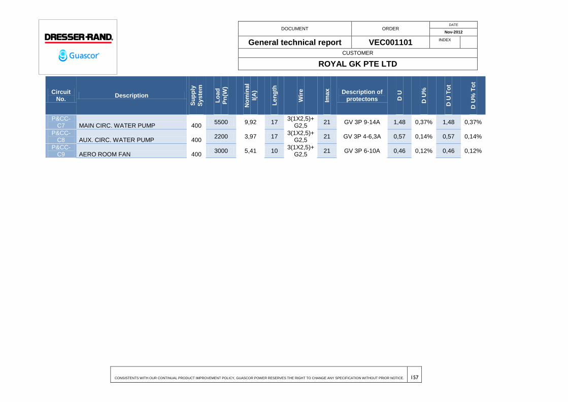
DOCUMENT ORDER DATE
Nov-2012
General technical report VEC001101 INDEX
CUSTOMER
ROYAL GK PTE LTD
CONSISTENTS WITH OUR CONTINUAL PRODUCT IMPROVEMENT POLICY, GUASCOR POWER RESERVES THE RIGHT TO CHANGE ANY SPECIFICATION WITHOUT PRIOR NOTICE. 157
Circuit No.
Description
Su
pp
ly
Sy
ste
m
Lo
ad
Pn
(W)
No
min
al
I(A
)
Le
ng
th
Wir
e
Ima
x
Description of protectons D
U
D U
%
D U
To
t
D U
% T
ot
P&CC-C7 MAIN CIRC. WATER PUMP 400
5500 9,92 17 3(1X2,5)+
G2,5 21 GV 3P 9-14A 1,48 0,37% 1,48 0,37%
P&CC-C8 AUX. CIRC. WATER PUMP 400
2200 3,97 17 3(1X2,5)+
G2,5 21 GV 3P 4-6,3A 0,57 0,14% 0,57 0,14%
P&CC-C9 AERO ROOM FAN 400
3000 5,41 10 3(1X2,5)+
G2,5 21 GV 3P 6-10A 0,46 0,12% 0,46 0,12%
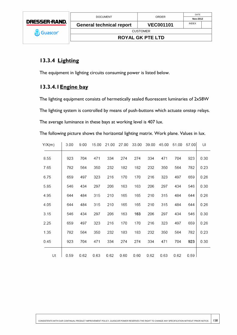
DOCUMENT ORDER DATE
Nov-2012
General technical report VEC001101 INDEX
CUSTOMER
ROYAL GK PTE LTD
CONSISTENTS WITH OUR CONTINUAL PRODUCT IMPROVEMENT POLICY, GUASCOR POWER RESERVES THE RIGHT TO CHANGE ANY SPECIFICATION WITHOUT PRIOR NOTICE. 158
13.3.4 Lighting
The equipment in lighting circuits consuming power is listed below.
13.3.4.1 Engine bay
The lighting equipment consists of hermetically sealed fluorescent luminaries of 2x58W
The lighting system is controlled by means of push-buttons which actuate onstep relays.
The average luminance in these bays at working level is 407 lux.
The following picture shows the horizontal lighting matrix. Work plane. Values in lux.

DOCUMENT ORDER DATE
Nov-2012
General technical report VEC001101 INDEX
CUSTOMER
ROYAL GK PTE LTD
CONSISTENTS WITH OUR CONTINUAL PRODUCT IMPROVEMENT POLICY, GUASCOR POWER RESERVES THE RIGHT TO CHANGE ANY SPECIFICATION WITHOUT PRIOR NOTICE. 159
13.3.4.2 Social building
The lighting system in social building consists of hermetically sealed fluorescent luminaries.
Lighting of various compartments in this building will be controlled by means of switches.
Average luminance in office areas at working level will be above 500 lux.
Average luminance in warehouses and workshops at working level will be above 300 lux.
13.3.4.3 Outdoor lighting system
The outdoor lighting system will consist of two circuits.
GSP-P7 circuit- Outdoor Lighting Lampost
GSP-P8 circuit – Outdoor lighting. Engine bay frontage.
Outdoor lighting will be controlled by mean of an astronomical clock.
GSP-P7- Outdoor Lighting Lampost
This lighting system consists of luminaries provided with 250W sodium vapor lamps
supported by a lamppost 12 m high.
The luminance measured at working level is of about 22 lux.
The following picture shows the horizontal lighting matrix. Work plane. Values in lux.

DOCUMENT ORDER DATE
Nov-2012
General technical report VEC001101 INDEX
CUSTOMER
ROYAL GK PTE LTD
CONSISTENTS WITH OUR CONTINUAL PRODUCT IMPROVEMENT POLICY, GUASCOR POWER RESERVES THE RIGHT TO CHANGE ANY SPECIFICATION WITHOUT PRIOR NOTICE. 160
GSP- P8 Outdoor lighting. Engine bay frontage.
This lighting system consists of luminaries provided with sodium vapor lamps and fixed to
bay frontage.
Average luminance at working level is of about 48,2 lux.
The following picture shows the horizontal lighting matrix. Work plane. Values in lux.

DOCUMENT ORDER DATE
Nov-2012
General technical report VEC001101 INDEX
CUSTOMER
ROYAL GK PTE LTD
CONSISTENTS WITH OUR CONTINUAL PRODUCT IMPROVEMENT POLICY, GUASCOR POWER RESERVES THE RIGHT TO CHANGE ANY SPECIFICATION WITHOUT PRIOR NOTICE. 161
13.4 TESTING & INSPECTION
13.4.1 Verification by checking
Checking the installed material no showing visible damage affecting safety. Verify
that are installed under current regulations and instructions of the manufacturer
Existence and calibration of protective and signaling devices. All are correctly
identified.
Existence and availability of schemes, warning and information panels
Check the correct execution of the lead connections
13.4.2 Checksbymeasurement or test
Earthground resistance test
Protective conductor continuity test
insulation resistance test between live conductors
Dielectric testing
Checking the tripping time and current of differential relays
Phase sequence test

DOCUMENT ORDER DATE
Nov-2012
General technical report VEC001101 INDEX
CUSTOMER
ROYAL GK PTE LTD
CONSISTENTS WITH OUR CONTINUAL PRODUCT IMPROVEMENT POLICY, GUASCOR POWER RESERVES THE RIGHT TO CHANGE ANY SPECIFICATION WITHOUT PRIOR NOTICE. 162
14 ENVIRONMENTAL POLLUTION SOURCES AND
MEASURES
14.1 STANDARDS BASIS OF DESIGN
The following directives and standards have been taken into account in environmental
matters:
Directive 2011/92/EU of the European Parliament and the Council of 13
December 2011 about assessment of aftermath of the effects of certain public and
private projects on the environment.
Directive 2010/75/EU of the European Parliament and of the Council of 24
November 2010 about industrial emissions (prevention and integrated control of
the pollution).
Directive 2008/98/EC of the European Parliament and of the Council of 19
November 2008 about waste and derogation of certain Directives.
Directive 2004/35/CE of the European Parliament and of the Council of 21 April
2004 about environmental liability related with the prevention and repairing of
environmental damages.
Directive 2002/49/EC of the European Parliament and of the Council of 25 June
2002 about assessment and management of environmental noise.
Directive 2001/80/EC of the European Parliament and of the Council of 23
October 2001 about limitations of air emissions of certain pollutants from large
combustion plants
Council Directive 96/61/EC of 24 September 1996 about prevention and control
of contamination.
EN-15259:2007 Air quality. Measurement of stationary source emissions.
Requirements for measurement sections and sites and for the measurement
objective, plan and report.
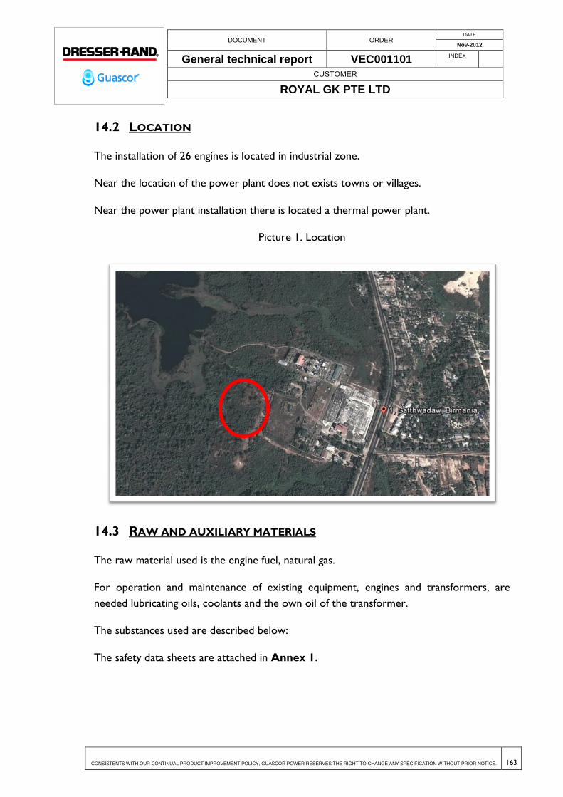
DOCUMENT ORDER DATE
Nov-2012
General technical report VEC001101 INDEX
CUSTOMER
ROYAL GK PTE LTD
CONSISTENTS WITH OUR CONTINUAL PRODUCT IMPROVEMENT POLICY, GUASCOR POWER RESERVES THE RIGHT TO CHANGE ANY SPECIFICATION WITHOUT PRIOR NOTICE. 163
14.2 LOCATION
The installation of 26 engines is located in industrial zone.
Near the location of the power plant does not exists towns or villages.
Near the power plant installation there is located a thermal power plant.
Picture 1. Location
14.3 RAW AND AUXILIARY MATERIALS
The raw material used is the engine fuel, natural gas.
For operation and maintenance of existing equipment, engines and transformers, are
needed lubricating oils, coolants and the own oil of the transformer.
The substances used are described below:
The safety data sheets are attached in Annex 1.
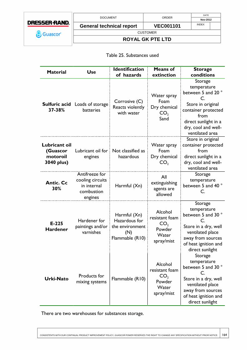
DOCUMENT ORDER DATE
Nov-2012
General technical report VEC001101 INDEX
CUSTOMER
ROYAL GK PTE LTD
CONSISTENTS WITH OUR CONTINUAL PRODUCT IMPROVEMENT POLICY, GUASCOR POWER RESERVES THE RIGHT TO CHANGE ANY SPECIFICATION WITHOUT PRIOR NOTICE. 164
Table 25. Substances used
Material Use Identification
of hazards
Means of
extinction
Storage
conditions
Sulfuric acid
37-38%
Loads of storage
batteries
Corrosive (C)
Reacts violently
with water
Water spray
Foam
Dry chemical
CO2
Sand
Storage
temperature
between 5 and 20 °
C.
Store in original
container protected
from
direct sunlight in a
dry, cool and well-
ventilated area
Lubricant oil
(Guascor
motoroil
3040 plus)
Lubricant oil for
engines
Not classified as
hazardous
Water spray
Foam
Dry chemical
CO2
Store in original
container protected
from
direct sunlight in a
dry, cool and well-
ventilated area
Antic. Cc
30%
Antifreeze for
cooling circuits
in internal
combustion
engines
Harmful (Xn)
All
extinguishing
agents are
allowed
Storage
temperature
between 5 and 40 °
C.
E-225
Hardener
Hardener for
paintings and/or
varnishes
Harmful (Xn)
Hazardous for
the environment
(N)
Flammable (R10)
Alcohol
resistant foam
CO2
Powder
Water
spray/mist
Storage
temperature
between 5 and 30 °
C.
Store in a dry, well
ventilated place
away from sources
of heat ignition and
direct sunlight
Urki-Nato Products for
mixing systems Flammable (R10)
Alcohol
resistant foam
CO2
Powder Water
spray/mist
Storage
temperature
between 5 and 30 °
C.
Store in a dry, well ventilated place
away from sources
of heat ignition and
direct sunlight
There are two warehouses for substances storage.
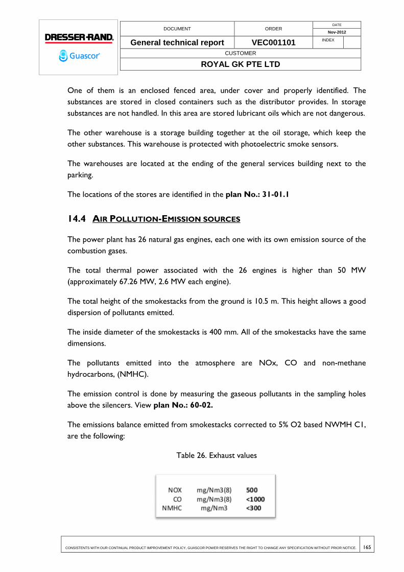
DOCUMENT ORDER DATE
Nov-2012
General technical report VEC001101 INDEX
CUSTOMER
ROYAL GK PTE LTD
CONSISTENTS WITH OUR CONTINUAL PRODUCT IMPROVEMENT POLICY, GUASCOR POWER RESERVES THE RIGHT TO CHANGE ANY SPECIFICATION WITHOUT PRIOR NOTICE. 165
One of them is an enclosed fenced area, under cover and properly identified. The
substances are stored in closed containers such as the distributor provides. In storage
substances are not handled. In this area are stored lubricant oils which are not dangerous.
The other warehouse is a storage building together at the oil storage, which keep the
other substances. This warehouse is protected with photoelectric smoke sensors.
The warehouses are located at the ending of the general services building next to the
parking.
The locations of the stores are identified in the plan No.: 31-01.1
14.4 AIR POLLUTION-EMISSION SOURCES
The power plant has 26 natural gas engines, each one with its own emission source of the
combustion gases.
The total thermal power associated with the 26 engines is higher than 50 MW
(approximately 67.26 MW, 2.6 MW each engine).
The total height of the smokestacks from the ground is 10.5 m. This height allows a good
dispersion of pollutants emitted.
The inside diameter of the smokestacks is 400 mm. All of the smokestacks have the same
dimensions.
The pollutants emitted into the atmosphere are NOx, CO and non-methane
hydrocarbons, (NMHC).
The emission control is done by measuring the gaseous pollutants in the sampling holes
above the silencers. View plan No.: 60-02.
The emissions balance emitted from smokestacks corrected to 5% O2 based NWMH C1,
are the following:
Table 26. Exhaust values

DOCUMENT ORDER DATE
Nov-2012
General technical report VEC001101 INDEX
CUSTOMER
ROYAL GK PTE LTD
CONSISTENTS WITH OUR CONTINUAL PRODUCT IMPROVEMENT POLICY, GUASCOR POWER RESERVES THE RIGHT TO CHANGE ANY SPECIFICATION WITHOUT PRIOR NOTICE. 166
14.5 NOISE SOURCES
The noise associated with each generation engine at 1500 rpm with fuel full load
according to the manufacturer is:
Table 27. Total sound level with engine running continuously, at 1500 rpm and
100% power.
The exhaust chimneys have a silencer to reduce the noise of exhaust gases, and the
closure of the engine rooms has been built with sound deadening materials. With these
measures of insulation, the noise distribution map obtained is the following:
Picture 2. Noise distribution map

DOCUMENT ORDER DATE
Nov-2012
General technical report VEC001101 INDEX
CUSTOMER
ROYAL GK PTE LTD
CONSISTENTS WITH OUR CONTINUAL PRODUCT IMPROVEMENT POLICY, GUASCOR POWER RESERVES THE RIGHT TO CHANGE ANY SPECIFICATION WITHOUT PRIOR NOTICE. 167
It’s possible to improve the noise level installing at the air ventilation inputs and outputs,
acoustic barriers that would improve the acoustic isolation. Ventilation has been designed
to allow this kind of improvement.
Picture 3. Noise distribution map with acoustic isolation at the air ventilation
system.
In this case the noise level reached in the surrounding industrial activities is lower than 45
dB (A). This level of noise is according with the current standards in noise matters for
industrial areas.
14.6 INDUSTRIAL SEWAGE WATER
The industrial sewage water associated with industrial activity carried out by power
generation of natural gas engines are the following:
o Network of sanitary sewage, from the existing toilets and showers. The sewage is
directed to a septic tank. It is a primary treatment unit of domestic sewage, inside is
performed the separation and physical-chemical transformation of solid matter
contained in those water. It is cleaned periodically by local operators.
o Network of rainwater from the downspouts from buildings. These waters do not
carry hazardous substances from the activity and go directly to the environment,
Hlawga Lake.

DOCUMENT ORDER DATE
Nov-2012
General technical report VEC001101 INDEX
CUSTOMER
ROYAL GK PTE LTD
CONSISTENTS WITH OUR CONTINUAL PRODUCT IMPROVEMENT POLICY, GUASCOR POWER RESERVES THE RIGHT TO CHANGE ANY SPECIFICATION WITHOUT PRIOR NOTICE. 168
o Network of rainwater from collection bunds of transformers. They are guided to the
intermediate manholes for each of the transformers. The manhole has valves that are
always closed so in case of accidental spill it can keep the residue in a safe place
pending of its removal. The spill is pumped into containers and taken to a local
operator for appropriate treatment. In case of rain, the manhole is checked to ensure
that it does not have any residue, and then the valve can be opened to drive the
rainwater to the network.
o Network of oil water from spills in the engine rooms, after passing through the grease
decanter. The waters spill from engines are carried to grease decanters where the oil
is separated from water by density and then the clean water passes to final discharge.
Greases are collected periodically for treatment by local operators.
o In the plan No.: 41-02, you can see the different wastewater networks.
14.7 INDUSTRIAL RESIDUES
The wastes generated in the activity are the following:
Table 28. Wastes generated
Waste Origin Storage Management
Motor oils and
lubricants used
Leaking engine and
motor circuits
In closed containers
in the warehouse
Treatment by local
manager
Waste coolant
(water glycols)
Accidental leakage
transformers
In closed containers
in the warehouse
Treatment by local
manager
Empty containers
with remnants of
hazardous
substances
Containers of
substances
In closed containers
in the warehouse
Treatment by local
manager
Absorbents and
cleaning cloths Clean spills
In closed containers
in the warehouse
Treatment by local
manager
There is an area identified for waste storage under deck and over concrete floor into the
warehouse.
The hazardous waste is regularly managed by local operators.

DOCUMENT ORDER DATE
Nov-2012
General technical report VEC001101 INDEX
CUSTOMER
ROYAL GK PTE LTD
CONSISTENTS WITH OUR CONTINUAL PRODUCT IMPROVEMENT POLICY, GUASCOR POWER RESERVES THE RIGHT TO CHANGE ANY SPECIFICATION WITHOUT PRIOR NOTICE. 169
14.8 ENVIRONMENTAL MEASURES FOR THE SITE SOIL
Industrial activity due to the power generation of the plant through gas fuel engines is
placed on native soil that never has hosted any other previous activity.
The plant has been designed according to an engineering basis “100% Environmentally
Friendly”, with the most advanced techniques in environmental matters.
The location where takes place the industrial activity has a concrete pavement that
protects the ground from spills of hazardous substances, and it is provided with a
drainage pipelines to avoid the uncontrolled spills.
There are two points of risk for ground contamination, spills from engines and
transformers. The spill risk is taken under control through the following measures:
The rooms where are placed the engines has a closures such as decks and
walls, and the floor is provided with a drainage network to drive the spills toward
a grease decanter manhole, which separate the oil from the water. The water
treated can be discharged in the lake near the plant and the grease will be
collected through pumps for its future management. The engines will be assembled
over a foundation to protect the ground of the building from vibrations and also
the accidentally spills.
The transformers are placed inside concrete cubes with the purpose of
keeping any oil spill and avoid its dispersion.
These spills are driven to separation manholes, one for each transformer,
which are connected to another larger manhole by valves that are always closed.
In case of rain, the content of the manholes is checked to ensure that there
are not any spills from transformers, and then the valve can be opened to
discharge the water in the large manhole, which is connected with the rain water
network.