General Standards ( EIA/TIA 568 B.2 1 Standard for · Section I General Standards ( EIA/TIA 568 B.2...
15
General Standards (EIA/TIA 568B.21 Standard for category 6 ) and Specifications for Inside and Outside Plant Wiring Practices USFSP St. Petersburg Regional Data Center (SPRDAC) 140 7 th Avenue South Bayboro Hall 241 St. Petersburg, Florida 33701 Office:(727) 8734552 Fax:(727) 8734160 A COPY OF THESE SPECIFICATIONS IS REQUIRED TO BE ON EVERY JOB SITE 9/8/2004
Transcript of General Standards ( EIA/TIA 568 B.2 1 Standard for · Section I General Standards ( EIA/TIA 568 B.2...
General Standards (EIA/TIA 568B.21 Standard for category 6) and Specifications for Inside and Outside Plant Wiring Practices
USFSP St. Petersburg Regional Data Center (SPRDAC) 140 7 th Avenue South Bayboro Hall 241
St. Petersburg, Florida 33701 Office:(727) 8734552 Fax:(727) 8734160
A COPY OF THESE SPECIFICATIONS IS REQUIRED TO BE ON EVERY JOB SITE
9/8/2004

USFSP St. Petersburg Regional Data Center (SPRDAC) 9/8/2004
A COPY OF THESE SPECIFICATIONS IS REQUIRED TO BE ON EVERY JOB SITE
TABLE OF CONTENTS
Section I General Standards (EIA/TIA 568B.21 Standard for category 6) and Specifications for Inside and Outside Plant Wiring Practices:
A. Contractor Requirements B. Quality, Craftsmanship, and Completeness C. Code Compliance
Section II Specifications
A. Outside Plant B. Entrance Facilities C. Entrance Cable Protection D. Entrance Cable Specifications 1. Twisted Pair 2. Fiber Optics E. MC (Main CrossConnect located in the main equipment room) / TR (Telecommunication Room housing the crossconnect between the backbone and horizontal cable) Architectural Finishes F. MC (Main CrossConnect located in the main equipment room) / TR (Telecommunication Room housing the crossconnect between the backbone and horizontal cable) Environmental Requirements G. Entrance Backboard/Main CrossConnect (MC) H. Conduit for Main CrossConnect (MC) and Telecommunication Room (TR) I. Telecommunication Room (TR) Backboard J. Cable Termination Blocks/Proper Tools K. Information Outlets (VoiceData Jacks) L. Information Outlet for Wall Mounted Height M. Labeling N. CCTV cabling, Security Lines, Fire Alarm Lines, Elevator Lines and Pay Phone Lines O. Conduit P. Cable runway and Pathways
Section III Testing
A. Outside Plant and Riser Cables B. Information Outlet Cabling C. Fiber Optic Cable D. CCTV and Security
Section IV Certification/ Acceptance
Section V Warranty

Note 1: All cabling will be done according to TIA/EIA 568B.21 Standards and wiring to be terminated to 568B Standard.
Note 2: SC connectors will be used for all Single Mode Fiber Secor Cam Locks (3M hot melt connectors.)
Note 3: ST connectors will be used for all Multi Mode Fiber Secor Cam Locks (3M hot melt connectors.)
Note 4: Hitachi Brand Cable is to be for all inside/outside Fiber & CCTV cabling and will terminate onto a rackmounted patch panel or cabinet.
Note 5: Data cables in telephone closet will be terminated onto a rack mounted superior cat 6, flexible snap in style patch panel not a 110 block with specified cable management.
Note 6: A Rack Mounted power strip is to be installed on the bottom of every installed rack.
Note 7: A Ladder rack will be installed horizontally across every MC (Main CrossConnect located in the main equipment room) / TR (Telecommunication Room housing the crossconnect between the backbone and horizontal cable) Back Board and out to the 19inch rack to about three (3) feet to four (4) feet. (See attachment)
Note 8: “AS BUILTS” As Built’s and test results are required to be turned into the Office of Campus Computing St. Petersburg Regional Data Center (SPRDAC) for the purposes of documentation updates.
Note 9: The color scheme for all riser cable labeling designation strips is “White”, and the color scheme for voice station cable labeling designation strips is “Blue”.
Note 10: USFSP uses a Cisco voice over IP phone system. Copper wire is no longer utilized to transmit voice communication at USF St. Petersburg between buildings. Fiber optic cable now carries all voice and data traffic between buildings. Voice jacks (grey in color at USF Tampa) is not specified in this document and should not be installed in any building as all voice traffic inside a building is now carried over the data port.
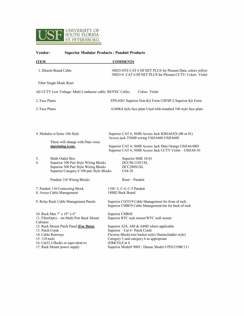
Vendor: Superior Modular Products / Panduit Products
ITEM COMMENTS
1. Hitachi Brand Cable 300258YE CAT 6 HI NET PLUS for Plenum Data; colors yellow 300258 CAT 6 HI NET PLUS for Plenum CCTV; Colors Violet
Fiber Single Mode Riser
All CCTV Low Voltage/ Multi Conductor cable; ISOTEC Cable; Colors Violet
2. Face Plates FPS0201 Superior NonKit Form USFSP2 Superior Kit Form
3. Face Plates A106K4 style face plate Used with standard 106 style face plate
4. Modules w/Icons 106 Style Superior CAT 6; 568B Access Jack KMJA6XX (00 or 01) Access jack T568B wiring UMJA606 UMJA608
These will change with Data voice imprinting icons Superior CAT 6; 568B Access Jack Data Orange UMJA608D
Superior CAT 6; 568B Access Jack CCTV Violet – UMJA610
5. Multi Outlet Box Superior SME 1001 6. Superior 100 Pair Style Wiring Blocks DCC96/11051XL
Superior 300 Pair Style Wiring Blocks DCC288S1XL Superior Category 6 100 pair Style Blocks C6410
Panduit 110 Wiring Blocks Riser – Panduit
7. Panduit 110 Connecting Block 110C3, C4, C5 Panduit 8. Avaya Cable Management 188B2 Back Board
9. Relay Rack Cable Management Panels Superior CO3519 Cable Management for front of rack Superior CMB19 Cable Management bar for back of rack
10. Rack Max 7’ x 19” x 6” Superior CMR45 11. FiberOptix – tm Multi Port Rack Mount Superior RTC rack mount/WTC wall mount Cabinets 12. Rack Mount Patch Panel (For Data) Superior A24, A48 & A48H where applicable 13. Patch Cords Superior – Cat 6– Patch Cords 14. Cable Runways Flextray Black(wire basket style) Damac(ladder style) 15. 110 tools Category 5 and category 6 as appropriate 16. Cat32 JHooks or equivalent to: (ERICO)Cat 6 17. Rack Mount power supply Superior Model# 9003 / Damac Model # PD1219BC111

Section I General
A. CONTRACTOR REQUIREMENTS
Qualifications: Final qualification to determine a successful contractor will be made by a USFSP Office of Campus Computing designated representative only. There will be a prequalifying procedure. This procedure will involve checking and verifying references. Contractor shall submit for approval, before work begins, three (3) references of work of a similar type and scale. References must contain names and telephone number of contact personnel. Contractor shall also submit names of technicians that will perform work specified herein, with documentation of schools and coursework (with Dates) indicating proficiency with the installation of data cable and fiber optic cable. The USFSP Office of Campus Computing designated representative; prior to the issuance of any purchase order or work authorization by Facilities Planning or general contractor shall approve this submittal. The contractor installing the telecommunications facilities and equipment herein specified shall be an experienced TELECOMMUNICATIONS CONTRACTOR. Experienced “meaning that the contractor has been in this type of business for a minimum of two (2) years and have personnel that have been trained and certified in the installation of telecommunications facilities Superior Modular Products and Panduit Products. Additionally, the Contractor will have successfully completed installation of similar equipment and size to that specified herein within the last year of Project.
Contractors must have a BICSI Registered/Certified Communications Distribution Designer (RCDD) on staff. Please furnish copy of current registration with submittal. Supervisor or Lead Tech on every project must have current Registered BICSI RCDD and/or Registered BICSI Technician Certification.
License and Codes: The successful Contractor must have applicable licenses (including but not necessarily limited to low voltage) and follow municipal codes for the areas in which projects are accomplished, to include NFPA, NEC, TIA/EIA/ANSI and BICSI.
Safety Procedures: HARD HATS and all other appropriate safety equipment shall be worn during all construction procedures. The vendor shall furnish appropriate safety equipment for their employees and construction site, to include safety zoning and the securing of all equipment and tools at all times. Must have first aid and safety training certificate provided to the University of South Florida Information Technologies’ representative prior to every project.
Damages: Any and all damages to property done by a Contractor will be the responsibility and liability of the Contractor. The USFSP Office of Campus Computing representative will designate all Telecommunications repair and USFSP Office of Campus Computing approved and qualified contractors “ONLY” are to be used.
Work Rules: Contractor’s employees must keep in mind during all contacts with client personnel that client satisfaction is paramount. Contractor’s employees’ speech, actions, dress and attitude must not detract from client satisfaction at any time. Contractor employees must keep in mind, however, that they are representing USFSP Office of Campus Computing and such contacts and avoid actions or speech that would reflect unfavorably on the department. During the execution of this contract, contractor personnel reflect upon the USFSP Office of Campus Computing. Contactor commits to maintaining high standards of professional conduct, neat and clean appearance of vehicles, equipment and personnel, and honest business practices are required. Parties agree that lackadaisical attitude of personnel, unwashed or battered vehicles, and misstatements on reports or invoices, and delayed payment of bills relating to such contracts are examples of unacceptable behavior. USFSP Office of Campus Computing requires all contractor personnel to dress appropriately for the task at hand. USFSP Office of Campus Computing requires all technicians

who perform fieldwork to drive a contractorprovided vehicle, which is clearly marked as belonging to the contractor. The vehicles can be any type preferred by the contractor as long as the vehicles are clearly marked, in good operating order, and have a good appearance. USFSP Office of Campus Computing shall retain the right to request the removal of any of the contractor’s personnel at any time.
B. QUALITY, CRAFTSMANSHIP, AND COMPLETENESS It is expected that the work completed under these specifications will be on the highest professional quality and craftsmanship. All systems furnished herein shall be complete and in compliance with manufacturer’s recommendations and designs. Contractor shall supply all components of the specified system as recommended by the manufacturer, whether specifically designated in these specifications or not.
C. CODE COMPLIANCE
The Contractor is responsible for compliance with all Federal State and Local codes that are applicable to electrical and telecommunications wiring and fire codes. If there is any conflict between these specifications and codes, the stringent requirement shall apply.
Section IISpecification
A. OUTSIDE PLANT B. All copper and fiber cables, to all building will only be installed by USFSP Office of Campus
Computing Dept. C. Will also use IT design to meet all needs for present and new technologies. D. Install copper cable and fiber optic cable from new facility or building to the closet serving wire center. The University has four (4) wire centers located on the Tampa Campus. These locations are ANDROS OFFICE CLASSROOM (AOC), EDUCATION BUILDING (EDU), ENGINEERING BUILDING II (ENB), and FLORIDA MENTAL HEALTH BUILDING B (MHB). The St. Petersburg Campus Wire Center is located at DAVIS HALL (DAV). The Sarasota Campus has two locations, HAMILTON CENTER (HCT), and PALMER A (PMA). The project must include necessary conduits, manholes, pull boxes, copper cable, and fiber to serve the building or facility.
Approved Manhole specifications are as follows:
Type “A” Manhole, 5feet in width x 10feet 6inches in length x 6feet 6inches in height. These are the same specifications as the GTE Model #GTS8395, a precast 2piece (see Attachment A). Manholes must include racks for cable, grounding buss bar, sump drain, and expansion plugs installed in non used conduits.
Approved Hand hole specifications are as follows: Brooks ProductsOrlando hand holes or approved equivalent shall be used where applicable. USFSP Office of Campus Computing will determine the use of hand holes in conjunction with Facilities Planning and Construction. Hand holes vary in size from 4feet by 4feet by 4feet to 8feet by 13feet by 4feet, all will include H.20 standards as to drive over characteristics.
Approved Conduit specifications are as follows: Schedule 40 PVC 20’ sections for straight runs and 90 degree 36 inches to 48inches radius: Factory made sweeps for turns.
Approved Inner duct specifications are as follows: Smooth wall or longitudinal ribbed inner duct, preferably tricolor (3 inner ducts in 4inch conduit w/color scheme of 1orange, 1blue, 1white), 11/4inches inside diameter with “mule tape” or polyethylene pull rope installed.
B. ENTRANCE FACILITIES
Install four (4) each, four (4) inch schedule 40 PVC conduits from the serving manhole (designated by USFSP Office of Campus Computing Representative) to the telecommunication entrance (EFEntrance Facility) room. The conduit will be stacked two (2) on two (2) and held in position by conduit positioning members designed for such purpose.
The conduits shall be concrete incased from the serving manhole line to the building entrance. The Minimum concrete coverage around the conduit shall be two inches. The conduit and concrete encasement shall be placed no less than twentyfour (24) inches below finished grade.
The conduits shall transition from schedule 40 PVC to rigid metallic, four (4) inch inside diameter for building entry. The metallic conduit shall extend out aMINIMUM of six (6) feet from the point of building penetration. The MINIMUM bend radius of the metallic conduit shall be fortyeight (48) inches.
The conduits shall enter the Main CrossConnect Frame/Entrance Facility and form a single line under the entrance backboard, no more than four (4) inches from the wall. The conduits shall be stubbed up above the finished floor no less than six (6) inches. The conduits shall be fitted with bushings to prevent cable damage when pulled during installation. The conduits shall be capped and sealed to prevent water and debris from entering.
Each conduit shall be left clean and dry and also left with a minimum of 250 pound test x ¼inch polyethylene Pull line. The other two conduits shall be clean and dry and one conduit will have three (3) Plastic Innerducts installed for the purpose of pulling fiber optic cable. Each Innerduct shall have its own 250 pound test x ¼” polyethylene pull line installed. Conduits shall be indelibly labeled.
The Contractor or Contractor’s are responsible for establishing with USFSP Office of Campus Computing representative, the location to which the conduit will be placed for connection to USFSP Office of Campus Computing Manhole System.
C. ENTRANCE CABLE PROTECTION (Copper Cable Entrance is no longer used at USFSP)
Twisted pair cable shall be equipped with transient voltage and sneak current protection for any inter building cable. The protector shall be ATT 188B1100 (Com Code 103314951) or approved equivalent with inbuilt 110tupe cross connect. Protector Mounts shall be used. These come standard with 25foot cable tails. Other lengths need to be researched prior to use. Each pair of cable protected shall be equipped with solidstate protector units with sneak current, solid state MOV protection.
Protection Modules shall be equipped at a 50% analog (1 st
50 pairs) and 50% digital (2 nd
50 pairs) ratio. The analog module required by the University of South Florida is AT&T model 4C1S230 (Com Code 104386545) or approved equivalent. The digital module required is AT&T 4C3S75 (Com Code 105 581086) or approved equivalent. The C3S75 protectors shall be installed on the high end of the cable count at each cable end (2
nd
50 pair).
D. ENTRANCE CABLE SPECIFICATIONS
1. Twisted Pair
Twisted pair cable shall be 24 AWG solid conductors and manufactured expressly for telephone use. The individual pairs must be color coded to the BELL SYSTEM/Telephone Industry Standards. Inner building cable shall be filled, for the purpose of water intrusion prevention, and composed of aluminum/steel sheath. Use AT&T Type ASP or approved equivalent.
Cable shall be sized and installed according to the schematic diagram for twisted pair. TwentyFour (24) core single mode fiber switch facility to building distribution facility. Only from Telecommunication Room to Telecommunication Room shall be MultiMode fiber and that will be 12 Core only.
Cables shall transition from outside (filled) cable to the “tails” of the protection units with properly equipped and installed splice enclosure units. Use AT&T Type 2000FR, 3M Better Buried, or approved equivalent. Use appropriate connectors for splices: AT&T 710 Bridge Connector or approved equivalent.
2. Fiber Optics
Fiber Optic cable shall be 62.5/125 um multimode and 50/125 umsingle mode (See USF Representative), multifiber filled (for water intrusion prevention) cable with nonmetallic components. It shall consist of 62.5 um core, 125 um cladding 250 um coating, and 900 um buffering. Maximum loss: 3.75 dB/km at 850 nm and 1 dB/km at 1300 nm. Minimum Bandwidth: 160 MHzkm at 850 nm and 500 MHzkm at 1300 nm. Numeric Aperture: .275. Cable must meet FDDI standards. Minimum cable pulling tension is 500lb. Minimum bend radius is 20 times the cable diameter.
Cable shall be sized and installed according to the schematic diagram for fiber optic cable. TwentyFour core single mode fiber switch facility to building Entrance facility.
Cable shall transition from outside, filled cable termination units through approved splice case or appropriate fiber breakout methodology that permanently prevents cable fill material from leaking. Multi Mode Fiber Optic Cable shall be terminated with ST ceramic connectors and Single Mode with SC connectors (AT&T C2000A series or approved equivalent). All fibers will be terminated in AT&T 100A2, 200A, 400A1 (sized according to cable) or approved equivalent termination Housings.
E. ENTRANCE FACILITY (EF) AND TELECOMMUNICATION ROOM (TR) ARCHITECTURAL FINISHES
Every building will have a main “Entrance Facility” and every floor per building will have its own individual (single/group) “Telecommunication Room”. Each EF (entrance Facility ) and TR (Telecommunication Room) telephone room shall be finished in the following manner:
No ceiling in room is required.
Flooring shall be tile or vinyl with a distributed load requirement of 250 pounds per square foot.
Lighting shall be a minimum 50 footcandles measured three (3) feet off of the floor with non EMI generating lights on a separate switch inside room and sheet rock finished walls painted with a white or off white color.
Room sizes for the EF’s are a minimum of 110120 square feet.
TR’s will be a “minimum” depth of five (5) feet and a “minimum” width of eight (8) feet with double doors to allow placement into hallways.
A fire extinguisher (CO2 or type dependant on local fire codes) hung INSIDE each EF and each TR.
All EF/TR and all their contents will be BONDED AND GROUNDED IN COMPLIANCE WITH THE TIA/EIA 568B.2 Industry Standard, as well as local, State and National codes.
F. ENTRANCE FACILITY and TELECOMMUNICATION ROOM ENVIRONMENTAL REQUIREMENT
Each of the Entrance Facility (EF) and Telecommunication Room shall maintain for 7 day/24 hours of an ambient temperature of 70 to 78 degrees Fahrenheit for the purposes of data distribution equipment (Ethernet Hubs and Routers, Switches, etc.).
G. ENTRANCE FACILITY BACKBOARD The entrance facility backboard will consist of two (2) four (4) foot by eight (8) foot, ¾” (4’ x 8’ x ¾”) plywood boards, securely fastened in a horizontal position to the designated wall. They shall be painted with gray, fireretardant paint, designated for such purposes.
There shall be two (Emergency Power if available) surface mounted, grounded, Quadplex outlets, one for each sheet of plywood supplied. Each electrical quad outlet shall be an isolated circuit, two (2) of 120V/20A. The electrical outlets shall be at the center, bottom of each sheet of plywood, no more than two (2) inches from the bottom. A rack mount power strip will be installed at the bottom of every rack. Superior Model 9003
H. CONDUIT FOR ENTRANCE FACILITY (EF) AND TELECOMMUNICATIONS ROOM (TR)
Provide two (2) 4inch EMT conduits between each EF and each connecting TR. Each conduit shall be left clean and dry and left with a minimum 250pound test pull line. Conduits shall be indelibly labeled as to their purpose (Example: Telecom IDF Room xxxx). Plastic bushings shall be placed on the ends of the conduit to protect the wires.
I. TELECOMMUNICATIONS ROOM (TR) BACKBOARD
The telecommunication room backboard will consist of two (2) 4foot by 8foot, 3/4inch plywood board, securely fastened in a horizontal position to the designated wall. They shall be painted with gray, fire retardant paint, designed for such purpose.
There shall be two (emergency power if available) surfacemounted, grounded, quadplex electrical outlets. Each quad shall be an isolated circuit, two (2) of 120V, 20A. The outlets shall be located at the center, bottom of each sheet of plywood, no more than 2inches from the bottom. If emergency power is available

please include BDF and IDF electrical outlets on Emergency Generator panel.
J. CABLE TERMINATION BLOCKS/PROPER TOOLS
All telephone cable shall be terminated on Superior connecting blocks, at the EF, and TR’s. This shall include wiring blocks, connecting blocks, and all label inserts. The general layout shall be as described in the diagrams (see Attachments B & C) provided. All termination of said cable will be ordered by room number e.g., Room 1 upper left of data patch panel and voice frame and Room 100 lower right of data patch panel and voice frame. Room numbers shall increment from left to right.
Voice cables shall be terminated on 110A type blocks, which require jumper cables to be punched down on the blocks. All 110C connecting blocks, c3, c4, and c5’s (PANDUIT used for riser only) will be terminated on the 110 block, with a 110 IMPACT TOOL, Model 788J1 or equivalent “ONLY.” And Category 6 with proper tool.
K. INFORMATION OUTLETS (VOICEDATA JACKS)
For each information outlet location designated, provide a Standard 2 port Category 6 data jack colored ORANGE mounted in an ivory triplex outlet cover. Terminations shall be in conformance with EIA/TIA 568B.2. Use Category 6 Superior Jacks. Faceplates shall be matching ivory to the electrical outlet and at the same height as electrical outlets located in the vicinity. Residence Housing will have a standard 2 port data outlet for each bed and the standard 2 data port outlet in all commons rooms. All Housing entry Phones will be the CEECO part number CEECO MODEL WPP531FY TELEPHONE with Optional 331016 spring loaded door.
All information outlets shall be marked at the point of manufacture with engraved letters indicating that the top jack is voice and the bottom jacks are data. For horizontally mounted information outlets, the left jack shall be voice and the right jacks are data. Conduits provided for outlets must have protective caps on end of conduit. The minimum requirement for all outlets is 1inch EMT conduit, for all outlets.
Each information outlet and its associated termination at the EF, or TR shall be labeled according to the following scheme:
ROOM NUMBERPOSITION IN ROOM CLOCKWISE FROM MAIN DOOR.
For example, the first jack to the left from the door in room J101 would be labeled: J101A. For example, the second jack to the left from the door in room J101 would be labeled: J101B. For example, the third jack to the left from the door in room J101 would be labeled: J101C, etc.
The information outlet shall be marked on the top right bevel of the faceplate. A black, finepoint “Sharpie” brand indelible pen is Mandatory for this purpose. Lettering shall be block letters and numerals, applied by the same individual for consistency.

L. INFORMATION OUTLET FOR WALL MOUNTED HEIGHT
All locations designated for hanging wall jacks shall be fitted with the information outlet as described in “INFORMATION OUTLET.” The outlet boxes shall be mounted 42 inches above the finished floor.
M. LABELING
All twisted pair terminations on 110 termination strips shall be marked with the jack number. For example: 103A. Placed on the top left incrementing to the right, then down to next row.
Fiber Cable: All fiber cable will be labeled with the same format as riser cable. Additional Outside plant labeling will contain Node locations and numbers. EF Room #XXXX/ TR Room #XXXX or in reverse order at the TR location. Building Node pairs XXXX/Building EF pairs XXXX or in reverse order at the Building EF.
N. SECURITY, FIRE ALARM, ELEVATORS AND PAY PHONES
Security, fire alarm, elevators and pay phone lines and station cable terminate at the bottom right of all patch panels and marked S, F, E or P/T. With multiples, use the following example: S1, S2, etc., F1, F2, etc., E1, E2, etc. O. A minimum diameter of 1inch emt conduit is to be used for all outlets. All conduits provided for
outlets must have protective caps on end of conduit and be grounded and bonded according to all Federal, State and local codes to include the NFPA, NEC, EIA/TIA/ANSI as well as BICSI codes.
P. Cable runways and pathways (cable tray) will have no obstructions (pipes, grid wire, AC ducts, ETC.) to keep form being able to lay cable in to tray.
Section III Testing
A. INFORMATION OUTLET CABLING
Contractor shall certify all station wire as to fext (far end cross talk) and other appropriate Category 6 tests. Results of said test will be submitted to USFSP Office of Campus Computing for building records, stored on a 3.5inch diskette.
B. FIBER OPTIC CABLE
All fiber optic cable shall be tested with a light source and meter at both 850 nm and 1300 nm. All fibers must test within the combined loss budget attributable to the cable length (3.75 dB/km at 850 nm and 1 dB/km at 1300 nm) plus the connectors (.25 dB per connector) and any splices (.25 dB per splice). In no case shall the loss budget for any single fiber optic run (connector to connector) be greater than 5 dB at 850 nm.
Contractor shall submit a record of all tests made indicating the fiber number and the loss at both wavelengths. Where applicable, on a 3.5 inch diskette.

Section IV Certification/Acceptance
All facilities will be inspected and tested by Owner or Owner’s agent. A list of facilities failing to meet specification will be provided to Contractor for correction. Only after all failures have been corrected and reinspected by Owner or Owner’s agent and certified within specification will all facilities be accepted.
Section VWarranty
All cable, terminations, and components of this cabling specification shall be warranted by the Contractor to perform as new for a period of three (3) years from date of system acceptance.
Attachments:
A. Manhole Spec B. BDF Suggested Layout C. IDF Suggested Layout D. Typical Parts on Job


September 8, 2004