General Specification for Civil Engineering and Building Design and ...
52
GENERAL SPECIFICATION FOR THE CIVIL ENGINEERING AND BUILDING DESIGN AND CONSTRUCTION OF 275kV & 400kV SUBSTATIONS SUB-03-034 Issue No 2 ________________________________________________________________________________ © SP Power Systems Limited Page 1 of 52 1 SCOPE This Specification outlines ScottishPower Energy Networks (SPEN) technical requirements for the civil design and construction of 275kV and 400kV Substations. The Constructor is entirely responsible for all aspects of the civil detailed design and construction process. This is a generic technical specification written in a manner that it may be used without alteration for all such works therefore certain parts may not be applicable to all substation construction types. It is not designed to cover every eventuality or site-specific situation; however, prior agreement must be obtained in writing from SPEN to any proposed variation to the guidelines provided in this Specification. Development of proposals for site-specific variation that are acceptable to SPEN shall be the Constructor’s responsibility. As far as is reasonably practicable, this Specification shall also apply to works at existing SPEN substation sites, however; this will be determined on a site-specific basis by agreement with SPEN, taking into account technical feasibility, cost and site-specific risk. 2 ISSUE RECORD This is a Reference document. The current version is held on the EN Document Library. It is your responsibility to ensure you work to the current version. Issue Date Issue No Author Amendment Details December 2015 Issue 01 Colin Ritchie First issue of document December 2016 Issue 2 Colin Ritchie General minor errors amended. Section 12.14 amended to reflect best practise, Section 12.7.2 updated to mitigate flood risk. Building Services Section 13 created and minor amendments made to building services requirements. 3 ISSUE AUTHORITY Author Owner Issue Authority Colin Ritchie Lead Engineer (Civil) Fraser Ainslie Engineering Design Manager Martin Hill Head of Engineering Design and Standards 4 REVIEW This is a Reference document which has a 3 year retention period after which a reminder will be issued to review and extend retention or archive. 5 DISTRIBUTION This document is not part of a Manual maintained by Document Control and does not have a maintained distribution list.
Transcript of General Specification for Civil Engineering and Building Design and ...

GENERAL SPECIFICATION FOR THE CIVIL ENGINEERING AND BUILDING DESIGN AND
CONSTRUCTION OF 275kV & 400kV SUBSTATIONS
SUB-03-034 Issue No 2
________________________________________________________________________________
© SP Power Systems Limited Page 1 of 52
1 SCOPE
This Specification outlines ScottishPower Energy Networks (SPEN) technical requirements for the civil design and construction of 275kV and 400kV Substations. The Constructor is entirely responsible for all aspects of the civil detailed design and construction process.
This is a generic technical specification written in a manner that it may be used without alteration for all such works therefore certain parts may not be applicable to all substation construction types. It is not designed to cover every eventuality or site-specific situation; however, prior agreement must be obtained in writing from SPEN to any proposed variation to the guidelines provided in this Specification. Development of proposals for site-specific variation that are acceptable to SPEN shall be the Constructor’s responsibility.
As far as is reasonably practicable, this Specification shall also apply to works at existing SPEN substation sites, however; this will be determined on a site-specific basis by agreement with SPEN, taking into account technical feasibility, cost and site-specific risk.
2 ISSUE RECORD
This is a Reference document. The current version is held on the EN Document Library. It is your responsibility to ensure you work to the current version.
Issue Date Issue No Author Amendment Details
December 2015 Issue 01 Colin Ritchie First issue of document
December 2016 Issue 2 Colin Ritchie
General minor errors amended. Section 12.14 amended to reflect best practise, Section 12.7.2 updated to mitigate flood risk. Building Services Section 13 created and minor amendments made to building services requirements.
3 ISSUE AUTHORITY
Author Owner Issue Authority
Colin Ritchie Lead Engineer (Civil)
Fraser Ainslie Engineering Design Manager
Martin Hill Head of Engineering Design and Standards
4 REVIEW
This is a Reference document which has a 3 year retention period after which a reminder will be issued to review and extend retention or archive.
5 DISTRIBUTION
This document is not part of a Manual maintained by Document Control and does not have a maintained distribution list.

GENERAL SPECIFICATION FOR THE CIVIL ENGINEERING AND BUILDING DESIGN AND
CONSTRUCTION OF 275kV & 400kV SUBSTATIONS
SUB-03-034 Issue No 2
________________________________________________________________________________
© SP Power Systems Limited Page 2 of 52
6 CONTENTS
1 SCOPE .......................................................................................................................................... 1
2 ISSUE RECORD ........................................................................................................................... 1
3 ISSUE AUTHORITY ...................................................................................................................... 1
4 REVIEW ........................................................................................................................................ 1
5 DISTRIBUTION ............................................................................................................................. 1
6 CONTENTS ................................................................................................................................... 2
7 GLOSSARY .................................................................................................................................. 4
8 RELATED DOCUMENTS ............................................................................................................. 6
8.1 European/British Standards: .................................................................................................. 6 8.2 International Standards: ......................................................................................................... 6 8.3 SPEN Documents: ................................................................................................................. 6 8.4 National Grid Documents: ...................................................................................................... 7 8.5 Government Publications: ...................................................................................................... 7 8.6 Industry Documents: .............................................................................................................. 7
9 INTRODUCTION ........................................................................................................................... 8
9.1 Feasibility ............................................................................................................................... 8
10 GENERAL REQUIREMENTS ..................................................................................................... 10
10.1 Consents .............................................................................................................................. 10 10.2 Pre-Engineering Studies ...................................................................................................... 10 10.3 Scheme Development .......................................................................................................... 11 10.4 Design .................................................................................................................................. 13 10.5 Substation Site Layout ......................................................................................................... 15 10.6 Setting Out ........................................................................................................................... 15 10.7 Services ................................................................................................................................ 15 10.8 Construction ......................................................................................................................... 15 10.9 As-Built Information .............................................................................................................. 16 10.10 Quality Assurance ................................................................................................................ 16
11 STANDARDS .............................................................................................................................. 17
12 TECHNICAL REQUIREMENTS .................................................................................................. 18
12.1 General ................................................................................................................................. 18 12.2 Site Clearance ...................................................................................................................... 18 12.3 Earthworks ........................................................................................................................... 18 12.4 Compound Construction ...................................................................................................... 18 12.5 Compound Earthing Systems .............................................................................................. 19 12.6 Roads and Footways ........................................................................................................... 19 12.7 Drainage ............................................................................................................................... 21 12.8 Oil Containment ................................................................................................................... 24 12.9 Fire Enclosures & Fire Barrier Walls etc to Outdoor Equipment .......................................... 26 12.10 Acoustic Enclosures and Barriers ........................................................................................ 27 12.11 Transformer Tank Enclosures – General Requirements (Fire & Noise Enclosures) ........... 28 12.12 Fencing to Substation Enclosures........................................................................................ 29 12.13 Power Fence Systems ......................................................................................................... 31 12.14 Temporary Fencing Systems for Site Segregation .............................................................. 33 12.15 Metalwork ............................................................................................................................. 33 12.16 AIS (Outdoor) Equipment Support Structures ...................................................................... 33 12.17 Woodwork ............................................................................................................................ 34 12.18 Concrete ............................................................................................................................... 34 12.19 Multi-Core Trench Systems .................................................................................................. 36 12.20 Access Covers (General) ..................................................................................................... 36
GENERAL SPECIFICATION FOR THE CIVIL ENGINEERING AND BUILDING DESIGN AND
CONSTRUCTION OF 275kV & 400kV SUBSTATIONS
SUB-03-034 Issue No 2
________________________________________________________________________________
© SP Power Systems Limited Page 3 of 52
12.21 Masonry ................................................................................................................................ 36 12.22 Pre-Fabricated Enclosures ................................................................................................... 37 12.23 Building Enclosures .............................................................................................................. 38 12.24 Landscaping Works .............................................................................................................. 46
13 BUILDING SERVICES ................................................................................................................ 47
13.1 Building Heating, Ventilation and Air Conditioning (HVAC) ................................................. 47 13.2 Building Electrical Systems .................................................................................................. 49 13.3 Security alarm systems ........................................................................................................ 51 13.4 Fire alarm systems ............................................................................................................... 51
14 POST-COMMISSIONING (RETURN) SITE VISIT ...................................................................... 52
GENERAL SPECIFICATION FOR THE CIVIL ENGINEERING AND BUILDING DESIGN AND
CONSTRUCTION OF 275kV & 400kV SUBSTATIONS
SUB-03-034 Issue No 2
________________________________________________________________________________
© SP Power Systems Limited Page 4 of 52
7 GLOSSARY
275kV and 400kV An assembly of High Voltage Switchgear up to 420kV together with associated Control and Ancillary equipment where the lowest voltage is 400/230V and which may also include one or more Transformers and/or Reactors at voltage levels of 400/275/220/132/33kV all housed within secure enclosures
Adopt Transfer of title, ownership, operation and maintenance responsibilities as defined in the adoption agreement
AIS Air insulated Switchgear
Approved Equipment which is Approved in accordance with SPEN documents for use or installation on the Company network
CDM Regulations Construction (Design and Management) Regulations
Civil Reference to civil or similar shall mean civil, structural and building engineering and shall apply to the design, manufacture, installation and demolition of all related permanent works
Company Refers to SP Distribution, SP Transmission and SP Manweb
Constructor The party, including IEC or other Third Party ‘Turnkey’ Design-Build Contractors and Third Party New Connection Developers and Contractors (ICPs), having ultimate responsibility for provision of the substation, including design and CDM.
Deemed to Satisfy Considered fit for the Company’s purpose and compliant in principle with this Specification by and without further reference to SPEN
Energisation: The application of Voltage to an item(s) of Equipment from the system
Equipment Switchgear, transformers, cables, overhead lines, surge arresters, voltage transformers, current transformers, protection & control, telecommunications, unit substations
GIS Gas insulated Switchgear
GRP Glass Reinforced Plastic
High Voltage An AC voltage exceeding 1000 volts measured between the phase conductors
ICP Independent Connection Provider
IEC Iberdrola Engineering and Construction
Indoor Equipment Equipment designed solely for installation within a building or other housing where the Equipment is protected against wind, rain, snow, abnormal dirt deposits, abnormal condensation and frost
LED Light Emitting Diode
LPS Loss Prevention Standards
Low Voltage (LV) An alternating current (AC) voltage not exceeding 1000 volts measured between the phase conductors
National Environment Agency
Environment Agency (EA) in England & Wales and Scottish Environment Protection Agency (SEPA) in Scotland
NGTS National Grid Technical Specification
Outage De-energisation of an item(s) of Equipment on the Company’s electricity network system
GENERAL SPECIFICATION FOR THE CIVIL ENGINEERING AND BUILDING DESIGN AND
CONSTRUCTION OF 275kV & 400kV SUBSTATIONS
SUB-03-034 Issue No 2
________________________________________________________________________________
© SP Power Systems Limited Page 5 of 52
Outdoor Equipment Equipment designed to be suitable for installation out with a building or other housing where the Equipment is not protected against wind, rain, snow, abnormal dirt/salt deposits, abnormal condensation and frost
SCADA Supervisory Control and Data Acquisition
SP Distribution Ltd The Distribution Licence Holder for the distribution service area
SP Manweb plc The Distribution Licence Holder for the distribution service area
SP Transmission Ltd The Transmission Licence Holder for the transmission service area
SUDS Sustainable Urban Drainage Systems
Transformers Reference to Transformers shall mean Transformers and Reactors

GENERAL SPECIFICATION FOR THE CIVIL ENGINEERING AND BUILDING DESIGN AND
CONSTRUCTION OF 275kV & 400kV SUBSTATIONS
SUB-03-034 Issue No 2
________________________________________________________________________________
© SP Power Systems Limited Page 6 of 52
8 RELATED DOCUMENTS
It is important that users of the documents listed below ensure that they are in possession of the latest issues of the documents.
8.1 European/British Standards:
BS 1722-12 Fences. Specification for steel palisade fences.
BS 1722-14 Fences. Specification for open mesh steel panel fences.
BS 1722-17 Fences. Specification for electric security fences. Design, installation
and maintenance.
BS 5266-1 Emergency lighting. Code of practice for the emergency escape
lighting of premises
BS 8000 Series Workmanship on construction sites,
BS 8500-1 Concrete. Complementary British Standard to BS EN 206-1. Method
of specifying and guidance for the specifier.
BS EN 124-1 Gully tops and manhole tops for vehicular and pedestrian areas
BS EN 206 Concrete. Specification, performance, production and conformity.
BS EN 12464-1 Light and lighting – Lighting of work places
BS EN 13030 Ventilation for buildings - Terminals – Performance testing of louvres
subjected to simulated rain
BS EN 60335-2-76 Specification for safety of household and similar electrical appliances.
Particular requirements for electric fence energizers.
8.2 International Standards:
IEC 61936-1 Power installations exceeding 1 kV a.c. – Part 1 “Common rules”
8.3 SPEN Documents:
EART-03-002 Technical Specification for Earthing 132kV S/S and above
SUB-01-012 Substation Fire Protection Policy
SUB-01-018 Substation Flood Resilience Policy
SUB-03-013 Specification for Prefabricated Substation housings for 12kV and 36kV
Switchboards
SUB-03-017 General Specification for the civil engineering and building design and
construction of Secondary Substations
SUB-03-018 Specification for Prefabricated Glass Reinforced Plastic Enclosures
SUB-03-025 General Specification for the Civil Engineering and Building Design and
Construction of Primary Substations.
SUB-03-026 General Specification for the Civil Engineering and Building Design and
Construction of 132kV Grid Substations

GENERAL SPECIFICATION FOR THE CIVIL ENGINEERING AND BUILDING DESIGN AND
CONSTRUCTION OF 275kV & 400kV SUBSTATIONS
SUB-03-034 Issue No 2
________________________________________________________________________________
© SP Power Systems Limited Page 7 of 52
8.4 National Grid Documents:
General for “National Grid”/“NG”/“the Client” read “the Company”, for “Contract
Administrator” read “SPEN” and for “Contractor” read “Constructor”.
NGTS 3.10 Series Generic Technical Specification (Construction) for Civil, Structural and
Building Engineering
8.5 Government Publications:
Department for Transport Traffic Signs Manual Chapter 8
8.6 Industry Documents:
National Structural Steelwork Specification for Building Construction (BCSA Publication)
Loss Prevention Standards – LPS 1175 - Requirements and testing procedures for the LPCB approval and listing of intruder resistant building components, strongpoints, security enclosures and free- standing barriers.
GENERAL SPECIFICATION FOR THE CIVIL ENGINEERING AND BUILDING DESIGN AND
CONSTRUCTION OF 275kV & 400kV SUBSTATIONS
SUB-03-034 Issue No 2
________________________________________________________________________________
© SP Power Systems Limited Page 8 of 52
9 INTRODUCTION
This document outlines SPEN’s technical specification requirements for the civil design and construction of 275kV and 400kV Substations. The Constructor is entirely responsible for all aspects of the civil detailed design and construction process.
This technical specification shall be used for 275kV and 400kV Grid Substations:
Substation Compounds housing Outdoor Equipment up to 420kV installed within and enclosed by a secure perimeter;
Substation Buildings housing Indoor Equipment up to 420kV installed within discrete purpose designed and traditionally built secure enclosures, with or without Outdoor Equipment (e.g. transformers or air insulated switchgear);
Substation Buildings housing indoor Gas Insulated Switchgear up to 420kV and associated plant installed within and enclosed by a secure perimeter.
Certain sections within this specification may not be applicable to all 275kV and 400kV Substation construction types and additionally the specification is not designed to cover every eventuality or site-specific situation
Project specific deviations from the design-build principles and construction details within this Specification will be considered by SPEN where the Constructor can demonstrate to SPEN’s satisfaction that they offer an equivalent or better technical and/or lower risk solution. All such deviations shall be fully discussed and agreed with SPEN within timescales that do not adversely affect project objectives.
Development of proposals for site-specific situations that are not covered by, and for deviations from, the guidelines within this Specification shall be the Constructor’s responsibility.
The technical specification for the civil engineering and building design and construction of Secondary and Primary Substations equipment enclosures and 132kV Grid Substations which can form an integral part of 275kV and 400kV Substation schemes shall be as follows:
Construction of Secondary Substations SUB-03-017;
Construction of Primary Substations SUB-03-025;
Construction of 132kV Substations SUB-03-026.
9.1 Feasibility
Once the requirement for a 275kV or 400kV Grid Substation has been established and the general arrangement of the substation has been agreed in principle by SPEN, it is important that during the detailed design stage any SPEN or statutory authority requirements highlighted during the feasibility phase and detailed in other referenced documents are given due consideration and are factored into the detailed design
In order to avoid possible abortive effort and subsequent delay; the Constructor shall confirm at the earliest opportunity how these requirements are to be met. This should be undertaken by discussing the principles at a Scheme Team meeting in order that any particular site specific issues can be factored into the substation design proposal. This should ensure that the design principles being adopted by the Constructor are acceptable to SPEN. These works shall include (but shall not be limited to):
Minimal Outages, Outage periods and the impact on existing assets;
Plant access/egress, including access routes and the method by which plant (including abnormal indivisible loads) will be installed/removed;
Operational, Inspection and Maintenance access and limitations on onerous activities;
24-Hour access/egress for SPEN personnel (Please note that access via third parties is not acceptable);
Emergency access/egress;
Fire segregation;

GENERAL SPECIFICATION FOR THE CIVIL ENGINEERING AND BUILDING DESIGN AND
CONSTRUCTION OF 275kV & 400kV SUBSTATIONS
SUB-03-034 Issue No 2
________________________________________________________________________________
© SP Power Systems Limited Page 9 of 52
Cable entries / routes;
Natural ventilation to Outdoor Equipment (e.g. transformers);
Avoidance of Noise pollution;
Avoidance of Flooding.
The preferred and optimum location for a 275kV or 400kV Grid Substation is on a generally level site with access from a public or private roadway.
275kV and 400kV Grid Substation compounds shall have 2m clear level access around the perimeter externally and SPEN shall have rights of access, operation and maintenance over this.
Actual clearances around substations and enclosures within substations shall be subject to the Constructor obtaining the express prior approval of SPEN with respect to requirements for operation and maintenance of the substation, plant access and cable/earth mat systems.
Enclosures to Outdoor Equipment that do not provide adequate natural ventilation shall not be acceptable.
GENERAL SPECIFICATION FOR THE CIVIL ENGINEERING AND BUILDING DESIGN AND
CONSTRUCTION OF 275kV & 400kV SUBSTATIONS
SUB-03-034 Issue No 2
________________________________________________________________________________
© SP Power Systems Limited Page 10 of 52
10 GENERAL REQUIREMENTS
10.1 Consents
Consents matters are outside the scope of this document but the Constructor shall ensure that all necessary notices and permissions are in place and that any associated applicable conditions are discharged prior to commencement of construction with respect to the following, where they apply:
Land Acquisition or Lease arrangements;
Planning Approval;
Building Control or Building Warrant Approval;
Fire Authority Approval;
Discharge consents, including where applicable Controlled Activities Regulations (CARs) License and legal rights to discharge for SPEN where this is other than direct to an adopted public system;
Environmental requirements (such as newt licences and the like);
Party Wall Etc Act, or where this is not applicable, prior formal notification of proposals to adjacent third-parties who potentially may be affected by the works;
Any other statutory or landowner consents that may apply.
10.2 Pre-Engineering Studies
10.2.1 General
The Constructor shall carry out adequate appropriate desktop and site-based Pre-Engineering Studies to provide the information necessary to ensure:
The safe transfer of design loadings to ground;
Compliance with respect to contamination and ground water risk;
Drainage discharge options are identified;
Environmental risks are identified and independently verified including ecology, noise nuisance and flood related risks.
The Constructor shall carry out any other studies considered necessary or appropriate on a site-specific basis.
Unless rock-head is confirmed as shallow by other means (e.g. trial pits) then as a minimum provision three boreholes shall be completed to each substation site taking account of proposed building and grid transformer locations within the works, in particular GIS buildings and multiple grid transformer locations. More boreholes shall be provided for complete new substation sites and for works within large or complex sites.
The Constructor shall carry out additional Pre-Engineering Studies as necessary where substations are located in complex situations, in particular where desktop studies indicate particular risks may be present including for example; brownfield sites, infilled sites, potentially contaminated sites, where piling or ground improvement may be required or where there has been previous deep or shallow mine working activity (coal, salt, metals, etc.).
Where ecology studies indicate that they are present, all traces of invasive plant species, e.g. Japanese Knotweed and Himalayan Balsam, shall be entirely removed in a controlled manner as necessary for the purpose of the works, including activities related to temporary site facilities and construction traffic. Provision shall be made to prevent these species from re-establishing in those areas.
Pre-Engineering Study records and reports shall be available for audit inspection by SPEN, including confirmation that:

GENERAL SPECIFICATION FOR THE CIVIL ENGINEERING AND BUILDING DESIGN AND
CONSTRUCTION OF 275kV & 400kV SUBSTATIONS
SUB-03-034 Issue No 2
________________________________________________________________________________
© SP Power Systems Limited Page 11 of 52
Worst case design load combinations would be safely transferred to suitable ground of adequate bearing capacity and that the extent of any potential future settlement would not adversely affect the operation of the substation, its infrastructure or its equipment (including cables/cable entries and other services);
The substation operation would not be adversely affected by a 1:1000 year flood event. Flooding of the substation during a 1:1000 year flood event will not lead to loss of supply or damage to key equipment within the substation. Vehicular access to the key plant and buildings within the substation is also required to be maintained;
The substation operation would not be the source of a 3rd
-party noise nuisance complaint in relation to transformers or other noise generating equipment (including ‘future’ nuisance complaint).
10.2.2 Existing Substation Sites
Additional surveys, visual inspections, non-destructive testing and intrusive testing/analysis shall be carried out , where necessary, to confirm the suitability of existing foundations or structures where it is proposed to utilises these as part of the new works.
10.2.3 Substation Earthing
The Constructor shall ensure that compound Earthing Systems are designed and installed in accordance with SPEN specification - EART-03-002.
10.3 Scheme Development
10.3.1 General
Subject to preliminary layout (feasibility) drawings being acceptable in principle to SPEN, it shall then be the Constructor’s responsibility to develop the scheme in detail in accordance with this Specification. Proposed General Arrangement and Construction drawings shall be submitted to include plans, elevations and sections of the buildings, structures and external works and shall clearly indicate the main dimensions, material and forms of construction proposed by the Constructor as follows:
Site location plan showing the whole of the site and access route, together with surrounding landscape and land use;
Site layout plan(s) showing the configuration of equipment and equipment enclosures within the site, together with setting out data, electrical clearances, site finishes, environmental mitigation, access roads, drainage, external lighting and security fencing;
General arrangement drawing(s) for buildings that include details of floor layout(s) and indicate dimensional access, operation and maintenance clearances between and around equipment;
o Sections, a minimum of two (one in each plane) for each enclosure, to include all cable entries and outgoing services, clear headroom to plant and relevant finished ground and floor levels;
o Elevations for the overall substation in total, including all buildings and equipment enclosures showing doors and any natural ventilation;
o Building services etc., e.g. small power, lighting, heating, ventilation, security alarm, direct mains water supply, etc;
o Earthing;
o Signage.
Other relevant information as applicable.

GENERAL SPECIFICATION FOR THE CIVIL ENGINEERING AND BUILDING DESIGN AND
CONSTRUCTION OF 275kV & 400kV SUBSTATIONS
SUB-03-034 Issue No 2
________________________________________________________________________________
© SP Power Systems Limited Page 12 of 52
Where applicable and considered appropriate by SPEN, typical deemed to satisfy substation layout drawings may be issued for guidance, either generic associated with this Specification or on a project-specific basis. Such drawings would indicate minimum dimensional requirements and would be based on optimum layouts for equipment, ventilation, plant/personnel access/egress and cable entry.
The Constructor shall make proper provision in the programme for both the design and construction and shall allow a minimum of 28 days for SPEN to comment on each design and drawing submission, including any proposed site-specific variation to this specification or associated typical deemed to satisfy details. The Constructor shall ensure that cognisance is taken of all such SPEN comments, however, acknowledgment of the Constructor’s design submissions by SPEN shall not relieve the Constructor of any design responsibility or any generic functional obligation of this Specification, nor shall it imply any liability on the part of SPEN.
10.3.2 Equipment Enclosures (Buildings, Containers/Housings & Compounds)
10.3.2.1 General (Indoor & Outdoor Equipment)
SPEN will only install equipment into or formally adopt Approved Equipment installed by others within enclosures that satisfy the requirements of this Specification. Selection of a particular type of enclosure may be subject to varying operational and supply requirements that take precedence over considerations of appearance, cost, local environment, etc.
Generic functional requirements include:
Suitable access for and cover to high and low voltage cables, including sealed cable entries to prevent below ground ingress of moisture, gas and vermin to buildings containing Indoor Equipment and escape of oil from enclosures containing oil filled Outdoor Equipment (e.g. transformers);
Security, in preventing hazardous intrusions as well as unauthorised entry;
Design to ensure no loss of supply or damage to key equipment within the substation during a 1:1000 year flood event.
10.3.2.2 Indoor Equipment
SPEN utilise proprietary prefabricated and traditional conventionally built housings for Indoor Equipment. Where these house 275/400kV switchgear the preferred enclosure type is a robust structural steelwork portal framed construction with a proprietary insulated steel sheet cladding system that is deemed to relieve and/or contain an internal pressure rise due to a disruptive failure of the plant.
Generic functional requirements include:
Weather-tight enclosure construction to prevent moisture ingress;
Preclusion of surface water run-off entry;
Suitable internal enclosure environment, in particular with respect to natural ventilation and the elimination of condensation;
Minimum 1-hour fire segregation between substation compartments.
SPEN accept that in particular site-specific environmental situations it may be necessary to consider alternative building or enclosure types. In such situations, the functionality requirements stated within this specification shall be factored into the building or enclosure design, together with any other relevant factors that are specific to the designed solution.

GENERAL SPECIFICATION FOR THE CIVIL ENGINEERING AND BUILDING DESIGN AND
CONSTRUCTION OF 275kV & 400kV SUBSTATIONS
SUB-03-034 Issue No 2
________________________________________________________________________________
© SP Power Systems Limited Page 13 of 52
10.4 Design
10.4.1 Design Methodology
Civil and building infrastructure in its entirety shall be designed to meet the functional requirements of the works for a minimum of 40 years. Where SPEN subsequently adopt the civil and building fabric, the design and construction detail shall be such that future inspection and maintenance is minimised with a first life maintenance of not less than 20 years.
Substation design shall take cognisance of Pre-Engineering Studies and shall be such that no sprinkler systems, gas, water, drainage or other third party service pipes, cables or heating and ventilation ducts are built within, through or beneath substations, in particular through or beneath equipment housings or supports within substations.
The Constructor shall adopt a design methodology that identifies all significant factors in the design and ensures proper attention is given to each factor at every stage in the design process. The Constructor shall prepare for the whole works and each discrete section thereof a Design Basis Statement which shall describe the high-level design philosophy and assumptions to be adopted and shall include but shall not be limited to:
Geotechnical Assumptions;
Foundation Design Concept;
Load Cases giving the magnitude of all dead, imposed, plant, wind and short circuit forces (etc.) considered to be appropriate for each structural element;
Load Case Combinations;
Support Structure and Building parameters.
Design Basis Statement shall identify applicable BS/BSEN documents.
Dead, imposed and dynamic loadings/actions for approved equipment are available from the manufacturers. Foundations and support structures to AIS Outdoor Equipment shall be designed such that these adequately resist short circuit forces, including vertically in the case of sealing end installations.
The detailed design submission must be in the English language and shall be prepared in terms of SI units in accordance with the recommendations of applicable BS/BSEN documents. All dimensions shall be in millimetres.
10.4.2 Flood Risk
Substations should be designed such that there is no loss of supply or damage to key equipment during a 1:1000 year flood event. Access routes to the substation should be considered to ensure access will be available during flood conditions and consideration of staff access to the key plant and buildings during the 1:1000 year flood event is also required.
Flood risk should consider Pluvial, Fluvial and Coastal flooding, as well as combinations of these.
275/400kV substation platforms shall be constructed at a minimum level of 500mm above the 1:1000 year flood levels, including consideration of a 50 year substation design life. The 500mm allows for climate change and uncertainties in data modelling. In those instances where there is a compelling reason to locate a substation inside this zone and this is accepted by SPEN the Constructor’s substation design shall eliminate or mitigate against the risk of such a flood impacting the operation of the substation (access requirements, loss of supply, or damage to equipment).
In addition, such schemes shall incorporate any requirement for compensatory storage as required by the Flood Risk Assessment (FRA) and be approved by the national environment agency or applicable local authority.
The Constructor shall obtain the written acceptance of SPEN to all proposed design measures to mitigate flood risk prior to construction.

GENERAL SPECIFICATION FOR THE CIVIL ENGINEERING AND BUILDING DESIGN AND
CONSTRUCTION OF 275kV & 400kV SUBSTATIONS
SUB-03-034 Issue No 2
________________________________________________________________________________
© SP Power Systems Limited Page 14 of 52
10.4.3 Structural Design
The structural design of the civil and building fabric is entirely the Constructor’s responsibility and shall be prepared, checked and approved to professionally recognised design Quality Assurance procedures by appropriately qualified and experienced Engineer, preferably a Chartered Civil or Chartered Structural Engineer. Design calculations shall be included within the CDM Health & Safety File.
Dead, imposed and dynamic loadings/actions for approved plant and equipment are available from the manufacturers. These values shall be used as the basis of the structural design loading to floors from Indoor Equipment and to plinths/support structures for Outdoor Equipment.
10.4.4 Disruptive Failure
Although substation equipment is extremely reliable and the probability of a disruptive failure due to internal arcing is very low this does have implications for both the design and location of substations. The Constructor shall ensure that substation designers are aware that considerable internal overpressure and fireball may be produced when this condition occurs.
Buildings enclosing 275kV and 400kV or lower voltage switchgear shall be designed such that they maintain their integrity and relieve or withstand the overpressure that can be developed during a disruptive failure under the most onerous simultaneous operation condition. Designers shall give due consideration to such potential for disruptive failure in their designs, including if necessary provision of pressure-relief panels to walls and roofs enclosing GIS equipment and in locating egress routes. Freestanding robust construction steel portal framed buildings with insulated steel sheet cladding that relieve and/or contain an internal pressure rise due to a disruptive failure being the preferred and most appropriate form of enclosure.
In line with the CDM design obligation to limit the risk associated with disruptive failure the preferred and optimum location for a substation is freestanding and detached from other development and every effort shall be made by the Constructor to comply with this requirement.
10.4.5 Fire Risk
The Constructor shall be responsible for ensuring that any necessary approvals are obtained from applicable fire authorities. Where applicable, any necessary fire certification shall be included within the CDM Health & Safety File handover to SPEN.
In addition a site-specific risk assessment shall be carried out that shall consider:
The likelihood of members of the public being in the vicinity/close proximity.
The substation type and location with respect to property types and public areas.
The transformer, plant, and insulant type.
The access/egress arrangements for members of staff/contractors.
The Constructor shall assess the fire risk and shall provide no less than the minimum mitigation measures to enclosures housing Indoor Equipment and to oil containing Outdoor Equipment (e.g. transformers and reactors) in accordance with this Specification and SPEN Substation Fire Protection Policy SUB-01-012.
10.4.6 Drainage Discharge
The Constructor shall be responsible for obtaining any necessary approval of proposals for discharge of storm, foul and oily water drainage systems from the national environment agency or applicable local authority before proceeding with the relevant construction work.
Any formal consent approvals shall be included within the CDM Health & Safety File together with, where applicable, any Controlled Activities Regulations (CARs) License and legal rights to discharge for SPEN where this is other than direct to an adopted public system.
GENERAL SPECIFICATION FOR THE CIVIL ENGINEERING AND BUILDING DESIGN AND
CONSTRUCTION OF 275kV & 400kV SUBSTATIONS
SUB-03-034 Issue No 2
________________________________________________________________________________
© SP Power Systems Limited Page 15 of 52
10.5 Substation Site Layout
Where typical deemed to satisfy substation layout drawings are issued for guidance by SPEN, the Constructor’s shall note that these are generic only and that the Constructor’s actual design proposals must reflect the supply-specific and site-specific situation.
The preferred and optimum location for a substation is freestanding on a generally level site with access at ground level from the public highway.
SPEN shall own or have rights over a minimum 2.0m wide strip outside the perimeter substation security fence.
Reliance on recourse to third parties for compliance with the requirements of this Specification to provide suitable unrestricted 24 hour access/egress for SPEN Authorised personnel would not be acceptable, and standard Company suited lock(s) must control this.
Oil Petrol Separators and where applicable septic tanks, cesspools and the like shall be sited adjacent or close to access roads to facilitate access for maintenance vehicles.
Constructors shall note that pedestrian safety barriers may be required where the site layout is such that emergency egress from the substation is towards a vehicular traffic route, and that these barriers would be required to be demountable if this were also a plant access route for the substation.
Constructors shall note that road restraint systems may be required external to the substation where the site layout is such that SPEN perceive there to be a risk of impact to the substation from vehicular traffic (e.g. substations adjacent to vehicle turning areas or where access roads are at a higher level).
10.6 Setting Out
It is essential that substations be set out in accordance with Land Acquisition and detailed design drawings where the Company have or will subsequently take freehold or leasehold possession of the land on completion.
10.7 Services
At existing sites all utility apparatus, including cables, pipes, trenches, buried earthing conductors and services of any kind (including spare ducts) which may be encountered during the course of the works are to be maintained in position, protected and kept in working order unless otherwise agreed by SPEN. The Constructor shall notify SPEN immediately where such apparatus is encountered. The Constructor shall record the accurate position and relative depth of these services during the course of the works and this information should be incorporated into the CDM Health & Safety File.
The Constructor shall be aware that the construction site may existing and new sites may be crossed by underground services, the location and depth of which may not be known. The Constructor shall undertake measures to prove the location of ALL underground services by detection and/or hand excavated trial pits prior to the start of the general site earthworks. The Constructor shall implement a system to permanently mark the routes of such underground services for the duration of the site works.
10.8 Construction
It is incumbent upon the Constructor to comply with all relevant legislation, including future updates and publications in keeping with industry best practice.
Where applicable and considered appropriate by SPEN, typical deemed to satisfy construction detail drawings may be issued for guidance, either generic associated with this Specification or on a project-specific basis. Constructors shall note that these details would be generic only with respect to such aspects as dimensions, handing, cable entries, etc.
The Constructor shall ensure that civil engineering and building contractors engaged to carry out works under this Specification are competent, qualified and experienced with respect to the nature of electricity substation construction. Civil and building contractors should hold appropriate membership of the National Federation of Builders, Federation of Master Builders, Civil Engineering Contractors

GENERAL SPECIFICATION FOR THE CIVIL ENGINEERING AND BUILDING DESIGN AND
CONSTRUCTION OF 275kV & 400kV SUBSTATIONS
SUB-03-034 Issue No 2
________________________________________________________________________________
© SP Power Systems Limited Page 16 of 52
Association or similar professional trade body. Operatives should hold appropriate Construction Skills Certification Scheme (CSCS) Cards or National Vocational Qualifications (NVQs); in particular welders shall be tested to meet and satisfy the requirements of the National Structural Steelwork Specification for Building Construction.
The Constructor shall be responsible for the design and construction of all temporary works deemed necessary to facilitate the construction works. All temporary works should be removed from site prior to project handover.
The standard of workmanship shall be in keeping with industry best practices and shall not be less than that specified by BS 8000.
The Constructor shall ensure that civil engineering and building contractors engaged to carry out works under this Specification take all reasonable precautions to ensure the safety of all parties concerned with or affected by operations associated with substation construction works.
The safety or operation of any existing Company utility plant must not be prejudiced; records of buried services must be obtained from all utilities and safe-digging practices must be adopted, including the use of a cable-locating tool.
The Constructor shall notify SPEN prior to commencement of substation construction works.
Substation construction shall be such that no sprinkler systems, gas, water, drainage or other third party service pipes, cables or heating and ventilation ducts are built within, through or beneath substations, in particular through or beneath equipment housings or supports within substations.
SPEN will not install equipment into substation enclosures until and unless all civil engineering and building works (except post-commissioning finishing works) are complete and are in accordance with this Specification. Unless variation has been agreed in writing by SPEN prior to construction, a delay in plant installation and/or energisation could result if works are not in accordance with this Specification.
SPEN will not consider formal adoption of Approved Equipment or civil infrastructure installed and commissioned by others until and unless all associated building and civil engineering works are complete and in accordance with this Specification, including receipt of As-Built information where applicable (i.e. in relation to adoption of the civil fabric of enclosures - buildings/compounds).
10.9 As-Built Information
As-Built drawings, Operating Manuals and CDM Health & Safety Files shall be submitted to SPEN in an agreed electronic format. To allow SPEN to manage their assets a Civil Asset Management Plan should be provided for each project. This document should be in an agreed format that will allow the development of an inspection and maintenance regime for the project.
10.10 Quality Assurance
All materials shall be of good quality, suitable for purpose, designed and manufactured such that they provide safe and continuous service and are capable of withstanding the various stresses and onerous conditions to which they may be subjected to on the site of installation without suffering any undue deterioration.
The Constructor is responsible for and shall ensure that all the listed duties of the Contract Administrator are carried out and completed with respect to civil quality assurance in accordance with the NGTS 3.10 series, in particular approval and sign-off of Inspections, Notification & Hold Points, Testing, Manufacturing Processes, Specialist Operative requirements and Document Submission - including off-site visits. This Clause shall not grant any right to the Constructor to vary the requirements of either this Specification or NGTS nor shall it detract in any way from SPEN’ rights.
SPEN shall have the right to inspect any aspect of the construction process. The Constructor shall ensure that all civil design and testing output are available for audit inspection by SPEN.

GENERAL SPECIFICATION FOR THE CIVIL ENGINEERING AND BUILDING DESIGN AND
CONSTRUCTION OF 275kV & 400kV SUBSTATIONS
SUB-03-034 Issue No 2
________________________________________________________________________________
© SP Power Systems Limited Page 17 of 52
11 STANDARDS
Civil and building infrastructure in its entirety shall be designed and constructed to comply with the following documents, unless expressly varied by this Specification:
SPEN Policy documents;
SPEN Specification documents;
NGTS 3.10 document suite - Generic Technical Specification for Civil, Structural and Building Engineering;
European Standards;
British Standards;
Codes of Practice;
Relevant Industry Guidance.
Some basic civil engineering and building technical compliance information that is contained within such documents is repeated within this Specification, over and above functional design and construction requirements, in order to assist in the initial development and costing of the civil aspects of substation projects.
Where associated Standards do not explicitly relate to civil, structural or building engineering but nonetheless contain requirements that may impact upon these aspects it shall be the Constructor’s responsibility to ensure a holistic and compliant overall design solution (e.g. in relation to earthing).
Building Regulations requirements shall apply unless stated or expressly implied otherwise within this Specification. Where literal compliance is not possible the work shall be to a standard agreed with SPEN that takes the Building Regulations as its basis.

GENERAL SPECIFICATION FOR THE CIVIL ENGINEERING AND BUILDING DESIGN AND
CONSTRUCTION OF 275kV & 400kV SUBSTATIONS
SUB-03-034 Issue No 2
________________________________________________________________________________
© SP Power Systems Limited Page 18 of 52
12 TECHNICAL REQUIREMENTS
12.1 General
Where applicable and considered appropriate by SPEN, typical deemed to satisfy substation construction detail drawings may be issued for guidance, either generic associated with this Specification or on a project-specific basis. Constructors shall note that such drawings would be typical only and that actual design proposals must reflect the actual supply-specific and site-specific requirements.
12.2 Site Clearance
Prior to the start of the construction works, the Constructor shall clear the site of all rubbish and debris and dispose of this off site. Debris shall not be burnt or buried on site. The Constructor shall, in accordance with any environmental constraints, remove all natural or man-made features where the position conflicts with the new works including fences, walls, trees and shrubs etc. and shall dispose of these off-site.
12.3 Earthworks
All foundations shall be set on undisturbed inorganic strata that provide a minimum design safe ground bearing capacity of 100kN/m².
The bottom of excavated areas shall be trimmed, levelled or graded and well rammed or otherwise compacted. The construction sequence shall be such that undue exposure of the formation level to excavations is avoided. Excavations shall be kept free from all water from whatever source.
Where a substation requires the use of reclaimed infill material this shall be demonstrably fit for purpose subject to the express prior acceptance of SPEN, including submission of a true representative sample for inspection and a suite of tests. These tests should demonstrate that the fill material can be suitably compacted, can resist the required allowable bearing pressures and axle loads reasonably anticipated and that the settlement characteristics with regard to tolerances can be reasonably achieved within the timescale of the proposed works without undue further settlement or ground heave which could potentially affect the operational aspects of the plant to be installed.
The works should ensure that further settlement or ground heave effects after the construction of foundations, access roads, buildings, underground services, cable trenches, security fences and walls are restricted to a maximum long term settlement of 25mm
Where the use of reclaimed infill is accepted it shall satisfy the requirements of this Specification and shall not contain any deleterious, degradable or non-degradable material of any size or proportion.
Any excess excavated material from the site which is unsuitable for use in the works (or in any designed landscaping mounds) must be removed from site to a suitable landfill site.
Excavations to reinforced concrete foundations shall receive a minimum 50mm thick layer of blinding concrete cover on completion.
12.4 Compound Construction
12.4.1 Stoned Compound Areas
Compound surfacing shall not be less than 300mm overall depth of construction; comprising:
A minimum 75mm layer of approved angular 14-20mm graded aggregate;
A minimum 225mm layer of approved Type 1/Type 3 granular layer compacted in a minimum of two layers;
An approved geotextile separation membrane should be provided between the sub-grade layer and the Type 1/Type 3 granular layer, unless the subgrade layer is a newly constructed platform with a minimum depth of 0.5m.

GENERAL SPECIFICATION FOR THE CIVIL ENGINEERING AND BUILDING DESIGN AND
CONSTRUCTION OF 275kV & 400kV SUBSTATIONS
SUB-03-034 Issue No 2
________________________________________________________________________________
© SP Power Systems Limited Page 19 of 52
Structural geotextiles or Geogrid reinforcement type systems shall additionally be designed and incorporated into the substation platform design where ground conditions dictate and where reinforcement and or separation of the underlying strata is required to provide increased ground bearing capacity and limit ground settlement.
Stoned areas generally shall be finished at or below the bottom of chamfers to structure foundations and the detail shall be such that trip hazards are avoided.
12.4.2 External Perimeter to Substation Compounds
275kV and 400kV Substations containing Outdoor Equipment shall incorporate a minimum 2m wide perimeter maintenance access footpath external to the substation footprint/security fence.
External perimeter footpaths shall be edged with a 200x50mm precast concrete edging kerb bedded and haunched in concrete The footpath shall not be less than 150mm overall depth of construction subject to removal of all organic soil matter; comprising:
A minimum 50mm layer of approved angular 6-10 mm graded aggregate;
A minimum 100mm layer of approved Type 1 granular sub-base compacted in a minimum of two layers;
An approved geotextile separation membrane below the Type 1 sub-base.
12.5 Compound Earthing Systems
12.5.1 General
Compound Earthing Systems shall be in accordance with SPEN specification - EART-03-002.
12.5.2 Installation
Earthing System installation shall be design and sequenced with the bulk earthwork and compound construction activities to minimise duplication of excavation.
Excavations shall be a minimum 300mm wide by 750mm deep (below finished compound level) with 150mm bed and backfilled with 300mm fine textured firmly rammed recovered topsoil or similar approved material all enclosed within a structural geotextile surround and with specified compound construction over. The Constructor’s detailed proposals shall be submitted to SPEN for comment prior to installation.
Installation of buried bare metal earth tape and earth rod systems to compounds shall be by SPEN approved specialist installers.
12.6 Roads and Footways
12.6.1 Road Crossings from Highways
Where vehicular crossings are required to highway footways or verges the design and construction shall be to the Local Authority’s approval and the Constructor shall be responsible for all notifications and Consents which may be required together with any associated fees.
12.6.2 Substation Access/Service Roads
275kV and 400kV Grid Substations shall have access roads that provide vehicular access and egress adequate for the safe operation and maintenance of the entire substation including access roads that facilitate; transformer and switchgear installation and future removal, access by mobile elevated working platforms (MEWPs) to AIS and GIS Compound areas and access by all other vehicles as necessary for general maintenance including gas trolleys where applicable.
Terminations to substation access roads that are within or offer entry into compound areas containing Outdoor Equipment with exposed Live conductors (‘Live compounds’) shall incorporate lockable barrier mechanisms to prevent access by unauthorised vehicles.

GENERAL SPECIFICATION FOR THE CIVIL ENGINEERING AND BUILDING DESIGN AND
CONSTRUCTION OF 275kV & 400kV SUBSTATIONS
SUB-03-034 Issue No 2
________________________________________________________________________________
© SP Power Systems Limited Page 20 of 52
The substation should be designed to ensure that MEWP access can be taken, over both access roads and the general compound, to all applicable Outdoor Equipment for maintenance purposes.
Access roads leading to substation compounds and around buildings shall be a flexible pavement construction. Kerbs should be provided where there is a requirement for an adjacent pedestrian footway. Where the access to a substation is via a granular track, then on a site-specific basis and by agreement with SPEN, the access roads around the compound and buildings may also be of a granular construction.
Substation access roads within ‘Live compounds’ shall be a granular Type 1 make-up and incorporate kerbs or other design measure to clearly define safe vehicle routes such that these deter vehicle entry towards Outdoor Equipment except at designated safe entry points that are controlled by lockable barrier mechanism.
Substation access roads within ‘Live compounds’ shall incorporate height gauge barriers at approaches to overhead or ‘over-sailing’ conductor systems (e.g. overhead lines, cables or bus bars).
Parking Areas adjacent to buildings shall provide a minimum 5 No parking bays for vehicles and turning areas for general maintenance vehicles that design out the risk associated with reversing out of the site.
Overall substation design shall facilitate the use of all substation access roads outside daylight hours.
The minimum clear width of substation access roads shall be as follows:
3.5m generally;
5.0m for grid transformer/reactor access, increased by a minimum 1m at bends of less than 30m radius unless swept path analysis requires this to be increased.
Construction of access roads shall be as follows:
Access roads within 'Live Compounds' - Dust blinded Type 1 with flush set kerbs;
Transformer Access Roads within 'Live Compounds' - Dust blinded Type 1 with flush set kerbs;
Building Access Roads - This road should reflect the construction materials of the Service Road leading to the compound gates.
Roads should be to the Constructor’s own site-specific design to suit actual ground conditions and anticipated loadings but shall not be less than 400mm overall construction thickness, inclusive of a structural geotextile membrane beneath sub-base where applicable.
12.6.3 Skidways to Grid Transformers
Where expressly required by SPEN on a project specific basis, reinforced concrete skidways shall be provided between substation access roads and 275kV and 400kV transformers and reactors, level transversely with a minimum 1% and maximum 3% longitudinally gradient.
12.6.4 Oil Tanker Delivery Areas to Substation Access/Service Roads
SPEN will proactively manage oil tanker delivery to mitigate spillage risk by controlled methodology and no specific measures are normally required to be incorporated into the design. Where expressly required by SPEN in response to regulatory authority requirements on a project specific basis, areas of substation access roads that are utilised for bulk oil transfer to 275kV and 400kV transformers or reactors shall incorporate measures to contain accidental spillage of oil. Spillage containment/collection within the access road shall be by means of upstand road kerbs, proprietary integral road-drainage kerbs and/or proprietary road channel drain systems - the use of ‘sleeping policeman’ type retention shall not be acceptable.
Vehicle standing areas associated with bulk oil transfer shall not be sited under or close to overhead or ‘over-sailing’ conductor systems (e.g. overhead lines, cables or bus bars).
Road construction to these areas shall be such that significant seepage of accidental oil spillage through the surface is prevented, the preferred surface being reinforced concrete such that it is not unduly damaged by oil spillage.
GENERAL SPECIFICATION FOR THE CIVIL ENGINEERING AND BUILDING DESIGN AND
CONSTRUCTION OF 275kV & 400kV SUBSTATIONS
SUB-03-034 Issue No 2
________________________________________________________________________________
© SP Power Systems Limited Page 21 of 52
12.6.5 Personnel Access
Enclosures shall incorporate approach and perimeter edged-paving surfacing to and between doors to facilitate personnel access.
Prefabricated paved areas shall comprise a maximum 600x600x50mm precast concrete paving slabs constructed on a minimum 50mm layer of sand-cement bed, constructed on a minimum 100mm compacted Type 1 granular sub-base. Perimeters to paved areas that are not otherwise contained by buildings, structures or road kerbs shall be edged with a 200x50mm precast concrete edging kerb set in a concrete haunch and foundation.
Cast in-situ concrete, asphalt or other alternative paving systems shall be subject to prior acceptance by SPEN.
12.6.6 Surfaced Areas for Equipment Access
Enhanced surface construction for equipment installation/removal shall be subject to prior acceptance with SPEN on a site-specific basis prior to construction.
12.6.7 Cable Duct Crossings
Cable crossings to roads within substations shall be robust rigid SPEN approved PVCu ducted systems with a minimum 150mm thick concrete surround and shall include draw cords and proprietary expanding foam or other approved temporary stop-ends to spare ways.
Ducted systems to each cable road crossing shall accommodate all cable requirements, including trefoil formations where applicable and cable requirements for identified ‘Future’ circuits/installations, together with not less than 10% overall spare capacity or three additional ducts (i.e. whichever is the greater) of the same type and diameter.
12.7 Drainage
12.7.1 General
Drainage systems shall meet the requirements of and be approved by relevant local authorities, utility companies and environment agencies.
The Constructor shall ensure that drainage schemes are adequately sized to accommodate flow rates that properly reflect the sources serviced by the system with systems designed to achieve self-cleaning non-scouring velocities.
The project Civil Asset Management Plan shall incorporate a Drainage Management section which shall provide details of the drainage infrastructure and highlight any critical or exceptional infrastructure. It should include details of the inspection and maintenance regimes required for each element of the infrastructure. Where infrastructure cannot be easily identified on site then a layout plan highlighting the locations of such infrastructure should be mounted within the substation building.
12.7.2 Surface Water
Surface water drainage systems shall be designed to ensure:
There is no flooding of the drainage system during the 1:25 return period event + 20% Climate Change;
There is no standing water that could impact on the operation, inspection and maintenance of the substation during the 1:1000 return period event;
These requirements need to be considered in association with the requirements of the “Flood Risk” section of this Specification.
With the exception of steel clad portal framed buildings, storm water run-off from buildings generally shall be collected by an appropriate system of rainwater goods that shall positively discharge to storm water drainage in a controlled manner.
GENERAL SPECIFICATION FOR THE CIVIL ENGINEERING AND BUILDING DESIGN AND
CONSTRUCTION OF 275kV & 400kV SUBSTATIONS
SUB-03-034 Issue No 2
________________________________________________________________________________
© SP Power Systems Limited Page 22 of 52
Storm water run-off from steel clad portal framed buildings shall be collected in a controlled manner to a land drainage system appropriate to the site. Positive collection of rainwater by guttering and downpipe rainwater goods systems shall not be utilised except where part of storm water harvesting systems.
The system shall be designed to ensure the minimum self-cleansing velocity in any pipe is 0.75m/s
and the maximum velocity in any pipe is 2.5 m/s.
SUDS features are likely to have a more onerous inspection and maintenance regime than traditional drainage systems. Therefore where there is a proposal to incorporate SUDS into a design this should be agreed with SPEN on a project specific basis such that it will allow SPEN to understand the implications of the proposed system.
12.7.3 Foul Water
Foul water drainage systems shall be connected to mains drainage wherever practicable. Where this is not practicable and SPEN will subsequently adopt the civil fabric then foul water drainage systems shall require minimum maintenance and be the most economical solution.
Cesspools shall be avoided as part of any SPEN adopted systems, however, where these are accepted by SPEN as the only practicable option then they shall not be less than 4,000-litre capacity and shall incorporate alarms connected and commissioned to the substation local alarm and SCADA system. All cabling (power and alarms) and connection to power supply shall be the Constructor’s responsibility but final connection and commissioning of alarms to the substation SCADA system shall be by SPEN.
12.7.4 Oily Water & Oil-Petrol Separators
Oily-water drainage systems shall be capable of safely containing a major escape of oil from transformers, reactors or storage oil tanks. Rainwater build-up within oil containment bunds shall not be discharged directly but shall be directed into an oily water drainage system via a sump. It shall be the Constructor’s responsibility to ensure that all appropriate local authority and national environment agency guidelines have been incorporated into the design of the oily-water drainage system.
Drains to oily water drainage systems shall be designed to carry fluids at 800C.
Oily-water drainage systems shall normally incorporate an Oil-Petrol Separator prior to discharge from the substation. Oil-Petrol Separators shall be proprietary National Grid ‘Type Registration Certificate’ full retention Class 1 Separators with integral silt collection and quality of discharge sampling facilities, together with integral coalescing and automatic closure ‘dead-stop’ mechanisms to prevent the flow through the unit in case of excessive oil levels. Coalescer units shall comprise oil resistant fire retardant material and be capable of removal for maintenance or replacement.
Oil-Petrol Separators shall be vented such that the build-up of potentially flammable or explosive vapour is prevented (as a minimum in accordance with the manufacturer’s recommendations) and shall incorporate alarms connected and commissioned to the substation local alarm and SCADA system, including a high oil level alarm. All cabling (power and alarms) and connection to power supply shall be the Constructor’s responsibility but final connection and commissioning of alarms to the substation SCADA system shall be by SPEN.
Separators shall have been type-tested to verify the stipulated design requirements for nominal flow rating, residual oil content of the discharge and water-tightness. A certificate stating details of its type-test, rating and class shall be provided with each unit.
By-pass type separators shall not be used.
Alternative systems will be acceptable including omission of an separators where i) expressly required on a project-specific basis by SPEN or ii) where justified by the Constructor’s own risk assessment on a site-specific basis, subject to provision of written confirmation from the national environment agency or other applicable local authority to SPEN that formal consent to discharge direct has been granted. In such cases alternative systems shall incorporate an oil separation/sampling chamber shall be installed as specified local to the point of discharge

GENERAL SPECIFICATION FOR THE CIVIL ENGINEERING AND BUILDING DESIGN AND
CONSTRUCTION OF 275kV & 400kV SUBSTATIONS
SUB-03-034 Issue No 2
________________________________________________________________________________
© SP Power Systems Limited Page 23 of 52
12.7.4.1 Oil Separator Design Note:
Separators shall be designed to accommodate the applicable run-off area or the worst case event of all bund pumps operating in unison, subject to national environment agency minimum size requirements as applicable – NGTS minimum size requirements shall not apply.
12.7.5 Oil Separator Sampling Chambers
Where consent has been confirmed by the national environment agency or other applicable local authority to omit the Oil-Petrol Separator, discharge water from bunds shall pass through a sampling chamber.
These sampling chambers shall as a minimum measure incorporate an integral oil separator plate and shall be of sufficient size to allow collection from flowing discharge, e.g. by means of raising inlets 100mm above outlets.
Where oil draw off comprising segregated sump, fire-trap and draw-off/sampling chambers are required on a project-specific basis by SPEN or shown to be necessary by the Constructor’s own site-specific risk assessment the design and method statements for operational use shall be subject to agreement with SPEN.
12.7.6 Oil-Petrol Spillage to Substation Access/Service Roads
Where substation access roads incorporate positive drainage systems and Oil-Petrol Separators are provided in association with pumped discharge from bunds enclosing oil containing Outdoor Equipment, then such road drainage consideration shall be given to draining to the oily water drainage system via the separator.
12.7.7 Road Channel Drain Systems
Where road channel drain systems are used to collect accidental oil-petrol spillage to roads these shall be proprietary heavy duty corrosion resistant grated top systems that incorporate precast polymer concrete or fibreglass channel sections.
12.7.8 Vented Battery Rooms
Requirements for drainage to bespoke Battery Rooms containing vented unsealed batteries shall as a minimum incorporate:
Natural ventilation such that these rooms are not designated as hazardous areas to BSEN standards;
Where connecting services to adjacent rooms cannot reasonably be routed externally these shall be kept to an essential minimum with robust durable seals that are fire-stopped and gas-tight;
Floors shall be of tanked acid resistant construction internally with sump facility for spillage collection;
Belfast Sink with potable cold water supply.
12.7.9 Soakaways
Soakaways shall be proprietary infiltration storm water management systems or as a minimum measure, in non-trafficked areas, infill pits or herring bone drainage systems filled with approved 32-40mm graded aggregate, all enclosed within a free-draining geotextile wrap to the Constructor’s design.
Where necessary based on risk assessment, soakaways shall additionally be lined with oil absorbent matting contained between geotextile membranes.

GENERAL SPECIFICATION FOR THE CIVIL ENGINEERING AND BUILDING DESIGN AND
CONSTRUCTION OF 275kV & 400kV SUBSTATIONS
SUB-03-034 Issue No 2
________________________________________________________________________________
© SP Power Systems Limited Page 24 of 52
12.8 Oil Containment
12.8.1 General
All oil containing Outdoor Equipment (e.g. transformers and reactors) and oil storage areas associated with oil filled cables shall be sited within oil-tight bund systems. Where practical, no part shall be sited within 50m of any well or borehole used for water extraction, 10m of any surface watercourse or 5m of any drain through which oil could enter and discharge directly into controlled waters.
No drainage, earth strip, cable or other service nor any duct or pipe shall pass through bund systems to the transformers. Power cables to associated auxiliary transformers and reactors may where necessary pass through bund systems provided these are within ducts and that cable entries in total are fully sealed to the satisfaction of SPEN (within and around ducts).
12.8.2 Bund Systems
Oil containment bunds generally shall be designed to safely contain a minimum of 115% of total oil content or where bunds contain more than one oil containing item of Outdoor Equipment (e.g. transformer or reactor) 125% of the capacity of the largest. In addition oil containment bunds shall be designed to also safely contain a minimum 100% of total oil content plus 150mm freeboard.
Oil containment shall otherwise satisfy all relevant national environment agency guidelines as applicable. Bund enclosures should be of reinforced concrete construction or other proprietary systems subject to prior acceptance by SPEN.
Where bunds are of reinforced concrete, they shall be not less than 225mm thick designed and constructed to retain aqueous liquids such that crack width is controlled by the reinforcement to limit this to 0.2mm. Wherever practicable, reinforced concrete bunds shall be of monolithic construction integral with support plinths. Where movement joints cannot be avoided then these shall incorporate proprietary cast-in hydrophilic seals or water-bars, non-absorbent joint filler and oil-resistant perimeter sealant. Where construction joints are necessary these shall have continuous reinforcement and incorporate proprietary hydrophilic seals cast-in centrally.
A sump shall be incorporated within bunds and shall be sized to ensure efficient operation of a bund water control system subject to a minimum of not less than 900mm x 900mm or equivalent area internally on plan and with a sump downstand of not less than 450mm.
Bund layout shall be such that, as far as is reasonably practical, any ‘spigot’ or jetting’ type flow is retained in the event of malicious damage or disruptive failure and that ‘personnel’ accessing completed bund structures do not compromise electrical safety clearance to exposed Live conductor and/or Insulator. The inner face of bund walls shall not be less than 2m clear on plan of oil containing parts.
Where required by SPEN on a project specific basis bunds to 275kV and 400kV transformers shall be designed to accept future installation of a proprietary noise enclosure mounted on the bund walls, including appropriate positioning of bund walls such that resonance does not occur.
Above ground bund walls shall not be less than 300mm above the adjacent internal and external finished surface level. Walls with an upstand of over 500mm to either side shall incorporate integral access and egress steps with anti-slip treads and demountable galvanised steel or GRP handrails on each side of the wall. If appropriate, walls that are relatively flush with ground level on each side (or buried) would be acceptable, for example, bunds comprising ‘moat’ type below ground only containment.
Where moat’ type below ground only containment installation is utilised to achieve electrical clearances and/or as an enhanced fire mitigation measure this shall be designed to be maintenance free for the design life period. All metal supports shall be of stainless construction and the layout shall be configured to prevent routine personnel access to the below ground areas, however; lockable flame-trapped man access and egress points (i.e. not less than two number in total) of not less than 600mm square shall be incorporated to facilitate inspection, either directly by personnel access or remotely by camera.
All bund systems shall be water tested on completion, prior to post-commissioning finishing works.

GENERAL SPECIFICATION FOR THE CIVIL ENGINEERING AND BUILDING DESIGN AND
CONSTRUCTION OF 275kV & 400kV SUBSTATIONS
SUB-03-034 Issue No 2
________________________________________________________________________________
© SP Power Systems Limited Page 25 of 52
Post-commissioning stone infill to bunds shall be a minimum depth of 300mm of approved angular 14-20mm graded aggregate and shall incorporate appropriate protection to cables running within. The stone infill shall be at or below the bottom of chamfers to plinths.
12.8.3 Bund Water Control Systems
Oil containment bunds shall be designed such that build-up of rainwater does not compromise design capacity.
Where discharge is direct to a separator this shall be via an inverted pipe arrangement and shall incorporate a fire trapped sump.
Where removal of rainwater build-up is by means of propriety bund water control system and there are no drainage outlets this shall have National Grid ‘Type Registration Certificate and be either:
A bund water control (intelligent pump) systems to discharging to an oily-water drainage system (i.e. to separator);
A complete Class 1 Certified Bund Dewatering System (incorporating integral separator);
These shall incorporate a point of isolation local to the control unit, anti-siphon device and alarms connected and commissioned to the substation local alarm and SCADA. system, including power or pump failure and high oil level alarms. The pump shall automatically deactivate if the sensor system detects oil during a normal water removal cycle, thus ensuring that no oil will be pumped out of the bunded area.
All cabling (power and alarms) and connection to power supply shall be the Constructor’s responsibility but final connection and commissioning of alarms to the substation SCADA system shall be by SPEN.
Alternative discharge systems may be acceptable subject to compliance with the requirements of this specification for oil water drainage
12.8.4 Water Test to Bund Systems
All bunds shall be water tested on completion as follows:
Seal all cracks exceeding 0.2mm in width using a resin injection or other approved proprietary system;
Temporarily remove the bund water control system.
Fill the bund with clean water to the maximum height permitted by SPEN but not less than equipment plinth level – record this level as datum;
Monitor and record the level of water over successive periods of not less than 48 hours until the fall in level over a period of 24 hours is less than 3mm, making allowance for both rainfall and evaporation;
At any point where the aggregate net fall exceeds 75mm the level of the water shall be topped back up to the datum level before resuming the test;
Allow for rainfall and evaporation by monitoring water levels in a suitable watertight control container of not less than 200 litres capacity filled approximately 50%;
Oil containing bunds shall be deemed to have failed the Water Test if the specified water retention has not been achieved within 7 days. In the event of failure remedial works shall be carried out as necessary to adequately seal the bund, which shall then be re-tested;
All test materials shall be removed from site on completion of successful water test, including environmentally controlled recovery or disposal of test water from within the bund.
Water Tests shall be witnessed by the Contract Administrator.
12.8.5 Fire Risk within Bund Systems
Subject to the Constructor’s fire risk assessment, alternative and/or additional fire containment measures may be necessary as follows:
Fire-trapped discharge into sumps with fire-sealed covers;

GENERAL SPECIFICATION FOR THE CIVIL ENGINEERING AND BUILDING DESIGN AND
CONSTRUCTION OF 275kV & 400kV SUBSTATIONS
SUB-03-034 Issue No 2
________________________________________________________________________________
© SP Power Systems Limited Page 26 of 52
Fire-trapped discharge into moat systems (oil storage below plinth/ground level);
Active Fire Detection/Extinguishing Systems;
Synthetic Ester Insulant to transformers (e.g. Midel);
Fire-trapped construction shall have minimum 4-hour fire resistance.
12.8.6 Fire-Traps
Fire traps shall as a minimum measure comprise a pit or chamber containing a 300mm depth of approved 32-40mm graded aggregate. Metal grating supporting this loose stone infill shall be designed such that it requires no maintenance for the design life of the works and does not restrict the flow oil or loose a significant proportion of its strength in the event of a fire.
Design details and method statements for access/egress shall be agreed with SPEN on a project-specific basis where provision for planned access to below ground containment areas is required.
12.8.7 Protection to Cables within Bund Systems
All cable routes within bund systems shall be agreed with SPEN on a site-specific basis prior to construction. Wherever practicable multicore cables shall be run on wall or compound surface mounted cable tray that does not present a trip hazard.
Power cables and where necessary multicore cables routed within stone infill shall be protected from mechanical damage by ducting or by a minimum of 150mm sand cover with structural geotextile over (to prevent migration of stone through the sand).
12.8.8 Emergency Spill Kits
Where SPEN own or will subsequently adopt oil containing Outdoor Equipment a freestanding mobile (wheeled) proprietary oil spill kit capable of managing spills up to 750L of oil shall be provided. This shall be at new sites and at existing sites where such facilities are not already in place.
12.9 Fire Enclosures & Fire Barrier Walls etc to Outdoor Equipment
The requirements for fire enclosures and walls and the protection of key plant and buildings shall be in accordance with the current SPEN Fire Protection Policy. Where no space constraints apply, transformers or reactors shall be segregated as detailed in Table 1.
Enclosures and/or fire barrier walls shall be provided as a minimum measure where segregation distances are less than those given in Table 1.
Fire enclosures and fire barrier walls shall provide a minimum 4-hour fire segregation.
Fire barrier walls shall as a minimum extend:
for a distance of at least 2m on either side of oil containing parts or explosion vents, or shall alternatively incorporate appropriately designed return walls;
for a distance of at least 1m above oil containing parts or explosion vents, however, electrical clearances shall not be prejudiced.
Subject to the outcome of the Constructor’s site-specific Fire Risk Assessment it may be appropriate or necessary to provide alternative or additional fire mitigation measures to Outdoor Equipment such as fire-trapped sumps to bunds, below-ground fire-trapped oil catchment (moat system), Active Fire Extinguishing Systems or Synthetic Ester Insulant (e.g. Midel).
Fire enclosures to transformer tanks shall be weather resistant proprietary demountable enclosure systems, proposed details of which shall be submitted to SPEN for comment and shall be subject to SPEN acceptance in principle prior to procurement.
The preferred construction type for fire walls is solid in situ (or precast panelled) reinforced concrete or proprietary demountable steel structures.

GENERAL SPECIFICATION FOR THE CIVIL ENGINEERING AND BUILDING DESIGN AND
CONSTRUCTION OF 275kV & 400kV SUBSTATIONS
SUB-03-034 Issue No 2
________________________________________________________________________________
© SP Power Systems Limited Page 27 of 52
Transformer or Reactor Type
Liquid Volume (litres)
CLEARANCE Between Bund & Adjacent
Oil Containing Parts or Other Oil Containing
Equipment (m) 1
CLEARANCE Between Bund &
Combustable2
Building Surface (m)
Oil Insulated Transformers
> 1,000 < 2,000 3 3.0 7.5
> 2,000 < 20,000 5.0 10.0
> 20,000 < 45,000 10.0 20.0
> 45,000 15.0 30.0
Less Flammable Liquid Insulated Transformers
All Volumes 0.9 Horizontal & 1.5 Vertical
Table 1 – Fire Segregation Requirements for Outdoor Equipment
Coolers to transformers shall not be enclosed to the extent that the detrimental effect on natural ventilation is unacceptable to SPEN. Forced electro-mechanical ventilation for cooling to transformers shall not be acceptable.
12.10 Acoustic Enclosures and Barriers
The substation layout shall incorporate acoustic enclosures or barriers where noise studies conclude that transformers or other equipment (e.g. compressors, filters, etc.) would give rise to a noise complaint. Calculations shall be provided, confirming that the acoustic design is such that a noise complaint would not arise subsequent to the installation of acoustic enclosures or barriers.
Coolers to transformers shall not be enclosed to the extent that the detrimental effect on natural ventilation is unacceptable to SPEN. Forced electro-mechanical ventilation for cooling to transformers shall not be acceptable.
Where required by SPEN on a project specific basis the substation design layout shall be such that it can facilitate installation of future acoustic enclosures or barriers where there is the potential for transformers or other equipment to give rise to a noise complaint from possible future developments adjacent to the substation site.
Enclosures shall be designed on a project specific basis to limit noise levels to meet the recommendations of associated pre-engineering Noise Studies and shall achieve an insertion loss of not less than 20dB at 100Hz.
Enclosures shall incorporate an acoustically absorptive inner surface that shall minimise internal reverberation and shall have adequate natural ventilation, which shall not promote corrosion of the equipment or of the enclosure elements nor compromise the overall acoustic performance.
The bund layout to 275kV and 400kV transformers shall be designed to accept installation of a future proprietary noise enclosure mounted on bund walls such that resonance does not occur within the enclosure.
1 It is not necessary to segregate or screen transformers (or reactors) up to 11kV or 33kV auxiliary
transformers from higher voltage equipment, the required segregation parameters for the lower voltage equipment would apply therefore in these circumstances. 2 A combustible building is defined as one that is constructed of a predominantly combustible material
such as timber. The distance to the building does not include the attached switch room but does include other SPEN substation buildings and 3rd party buildings. 3 Subject to site–specific Fire Risk Assessment, oil insulated equipment containing less than 1,000
litres may require fire mitigation measures to be applied in high risk locations or situations.

GENERAL SPECIFICATION FOR THE CIVIL ENGINEERING AND BUILDING DESIGN AND
CONSTRUCTION OF 275kV & 400kV SUBSTATIONS
SUB-03-034 Issue No 2
________________________________________________________________________________
© SP Power Systems Limited Page 28 of 52
12.11 Transformer Tank Enclosures – General Requirements (Fire & Noise Enclosures)
Fire and acoustic enclosures to transformer tanks shall be weather resistant proprietary systems, proposed details of which shall be submitted to SPEN for comment and agreement in principle prior to procurement and shall as a minimum incorporate:
Four walls and a roof that are structurally independent with no reliance on connections to the enclosed equipment for its stability and integrity, physically isolated from any vibrating parts of the equipment.
A line of weakness in the overall construction immediately above the support where enclosures are mounted on bund walls, to ensure that the bund remains intact in the event of a disruptive failure.
Two personnel access doors positioned diagonally opposite each other.
A demountable design such that it can be installed and dismantled without the need to remove any part of the electrical system, either outside or within the enclosure.
Weathering that is an intrinsic part of the of the enclosure design such that there is no reliance on products such as membrane systems or sealants that are applied post installation
A non-slip oil-resistant roof surface that is positively drained to the transformer oil containment bund area via guttering and downpipes such that oil resulting from a turret bushing failure is contained.
A stainless steel plate detailing the enclosure manufacturer’s name and address together with the acoustic performance characteristics shall be fixed to the external face of the enclosure in an accessible and viewable location.
Demountable and easily removable access panels to facilitate plant maintenance.
Connection of metallic parts to the substation earthing system.
Internal lighting with a minimum maintained illuminance of 150 lux at floor level, together with 3-hour self-contained maintained emergency lighting with test key-switches that achieves 2.5 lux at floor level.
External lighting.
All lighting shall be controlled by an external IP 65 rated light switch positioned adjacent to each personnel access door.
An externally rated (IP 65) double 13 amp 240 volt switched socket outlet within the enclosure.

GENERAL SPECIFICATION FOR THE CIVIL ENGINEERING AND BUILDING DESIGN AND
CONSTRUCTION OF 275kV & 400kV SUBSTATIONS
SUB-03-034 Issue No 2
________________________________________________________________________________
© SP Power Systems Limited Page 29 of 52
12.12 Fencing to Substation Enclosures
12.12.1 General
The level of security to be provided by the fence shall be discussed and agreed with SPEN and ScottishPower Corporate Security.
As a minimum measure 275kV and 400kV Grid Substations shall be enclosed by Security Fencing such that there is a minimum 2.4m overall height clearance to perimeter security fencing within 2.0m external to the line of the fence. Security Fencing shall be a minimum of 2.4m overall height above any potential climbing aid (horizontal climbing aids, anti-dig security kerb or bund wall).
Anti-climb measures shall be incorporated within Security Fencing systems where this presents ‘internal corners’ external to the fence, abuts substation buildings or, where agreed with SPEN as an alternative to raised fencing, external fences or potential climbing aids within 2.0 m external and internal.
All SPEN Transmission sites and other substations classified by ScottishPower Corporate Security as critical or strategically important for supply or as high risk sites with respect to the potential for unauthorised entry (e.g. theft or vandalism) shall be enclosed by High Security Fencing, which shall be a minimum of 3.0m overall height above anti-dig security kerb. These will be identified by ScottishPower Corporate Security on a site-specific basis.
Wherever practicable Security Fencing shall be either palisade, proprietary expanded metal or open mesh steel panel systems which cannot be scaled without climbing aids.
Typical deemed to satisfy construction detail drawings for security fencing may be available for issue from SPEN for guidance, Constructor’s shall note that these details would be generic only.
All fencing shall be hot dip galvanised steel in accordance with this Specification. Hot dip galvanised materials shall not be post drilled; fixings to be made after galvanising shall be made with clamped fixings by prior agreement with SPEN.
Notwithstanding the stated minimum requirements of this Specification, structural performance shall be the Constructor’s responsibility with respect to site-specific conditions including the nature of the ground, topography, applied lateral loading and overall fence height.
The installation of Earthing and all “property” and “Danger of Death notices” to fence panels shall be the Constructor’s responsibility.
Construction of security fencing immediately adjacent to the position of a transformer or reactor shall be such that it is readily demountable to allow equipment to be removed for maintenance or replacement.
The design and fabrication of fencing systems shall make allowance for appropriate connection of earthing.
12.12.2 Gates
Gates shall provide the same (minimum) level of security as, and be compatible with, the associated fence to either side.
Unless expressly agreed otherwise with SPEN on a site-specific basis prior to construction, the entry sequence shall be such that single personnel gates are accessed first, with no external locking mechanisms to double vehicular gates (i.e. opening from the inside only).
Locking arrangements to gates shall be expressly agreed with SPEN on a project-specific basis prior to procurement. Locks, handles and cut-outs for these shall incorporate integral shrouds such that they do not present potential climbing aids.
Hinge mechanisms to the gates shall be tamper-proof and obscured from the outside with metal fabricated shrouds to prevent access such that they do not present potential climbing aids. The spigot of the top hinge shall be reversed to point downwards to prevent the gate being lifted off.

GENERAL SPECIFICATION FOR THE CIVIL ENGINEERING AND BUILDING DESIGN AND
CONSTRUCTION OF 275kV & 400kV SUBSTATIONS
SUB-03-034 Issue No 2
________________________________________________________________________________
© SP Power Systems Limited Page 30 of 52
Vehicular gates shall have clear openings not less than the width of the associated road or 4.0m whichever is the greater. Personnel gates shall have clear openings appropriate for their required operational use subject to a minimum of 900mm.
The arrangement of gates must take cognisance of the road design where a camber or crossfall is incorporated such that the maximum clear space beneath a gate in the closed position shall not exceed 70mm.
Where Power Fences are to be installed gate posts shall extend to the same overall height as the electric pulse system.
12.12.3 Palisade Fencing Systems - Security & High Security;
Security and High Security palisade fencing systems shall have SP (security) standard of fixings and pale details to BS 1722 Part 12 that incorporate:
Tamper resistant bolt and shear nut fence panel fixings;
Heavy duty 4.0mm thick ‘D’ section pales with single point or Heavy duty 3.0mm thick ‘W’ section pales with tamper resistant swaged pin and collar grooved fasteners having special formed heads to suit pale profile;
Maximum 85mm clear space between pales;
Maximum 50mm clear space beneath pales;
Minimum 65 x 50 x 6mm rail sections, or minimum 75 x 50 x 6mm to gradients exceeding 1 in 6 over more than two panels;
Vertical posts to be minimum 102x44x7kg/m, or equivalent, post sections.
In addition High Security palisade fencing shall be SP (security) standard systems to BS 1722 Part 12 that incorporates:
3 No horizontal rails 50x50x6mm with countersunk holing and V slot for pale insertion;
Vertical posts to be minimum 127x76x13kg/m UB Pointed, or equivalent, with 150x100x10mm baseplate.
12.12.4 Mesh Fencing Systems - Security & High Security;
Security mesh fencing systems shall be open mesh steel panel systems with Category 4 (extra-high security) standard of fixings and mesh panel details to BS 1722 Part 14 that incorporate:
Tamper resistant cup headed bolts into full height flat metal plate fixing strips bolted full depth through posts to nuts on inner rear face;
Welded mesh type panels with maximum 12.5 x 75mm mesh spacing, minimum 4mm thick wire;
or
Expanded metal type panels with maximum 10mm x 70mm mesh spacing with 3mm thick strand (5.5mm wide main strand);
Minimum 80 x 80 x 3.5mm thick square hollow section posts.
In addition High Security mesh fencing shall be Category 4 (extra-high security) standard systems to BS 1722 Part 14 that in addition to the above incorporates:
Individual fence panels (not continuous construction);
Additional stiffening wires to welded mesh panels to avoid ‘bowing’ (not applicable to expanded mesh panels);
Minimum 100 x 100 x 4.0mm thick square hollow section posts.

GENERAL SPECIFICATION FOR THE CIVIL ENGINEERING AND BUILDING DESIGN AND
CONSTRUCTION OF 275kV & 400kV SUBSTATIONS
SUB-03-034 Issue No 2
________________________________________________________________________________
© SP Power Systems Limited Page 31 of 52
12.12.5 Post Pockets
Ground mounted posts to Security Fencing shall be set within in situ concrete minimum 0.9 x 0.9 x 0.3m deep pads or minimum 0.45 x 0.45 x 0.9m deep pockets.
Ground mounted posts to High Security Fencing shall be set within in situ concrete pockets minimum 0.6 x 0.6 x 1.0m deep.
Where posts are set within or atop reinforced concrete walls (including to bunds) these walls shall not be less than 300mm thick.
Post foundation design shall allow for any height/load increase associated with attached or proposed future anti-climb barriers or electric pulse Power Fence in addition to any site-specific conditions.
12.12.6 Anti-Dig Security Kerb
Security fencing shall incorporate anti-dig measures below the fence panels. This shall be either;
A concrete beam not less than 200mm wide x 300mm deep, incorporating 25mm chamfers to top edges and set a maximum of 50mm beneath the fence panels;
A trench, a minimum 200mm wide x 300mm deep, filled with approved 14-20mm graded aggregate;
12.12.7 Anti-Vandal Scaling Barriers (Anti-Climb Mechanisms)
Anti-climb mechanisms shall be approved rotating proprietary anti-vandal anti-scaling barriers, fixed such that support brackets are set one vane in from exposed ends to avoid presenting a climbing aid. Barbed wire or barbed tape anti-climb measures shall not be acceptable.
12.12.8 Coloured Fencing Systems
Appropriate painted systems may be applied after erection but pre-coated systems that impair electrical continuity for earthing purposes shall not be acceptable.
Where SPEN will subsequently adopt the civil fabric of the substation and paint systems to galvanised fencing are necessary then these shall comprise:
Etch coat and wash preparation, including spot priming with one coat zinc phosphate primer to any areas where the galvanising has been damaged or bare ferrous metal is exposed;
65 microns: SINGLE-COAT quick drying water-based metal primer designed to provide excellent adhesion to the surface of new bright or weathered galvanised metal surfaces;
80 microns: TWO-COAT build-up of gloss finish specially formulated for metal with a quick drying solvent-based formulation that can be over-coated within 4 to 6 hours (depending upon conditions).
12.13 Power Fence Systems
12.13.1 General
Power Fence systems shall be installed to enhance Security Fencing in locations deemed appropriate by ScottishPower Corporate Security.
Power Fence systems shall be High Voltage electric pulse fence systems that comply with BS EN 60335-2-76, and BS 1722-17; installed on the secure (internal) side of all perimeter fencing and gates.
Power Fence systems shall be appropriately zoned by agreement with SPEN. Alarms shall be connected and commissioned to the substation local alarm and SCADA system. All cabling (power and alarms) and connection to power supply shall be the Constructor’s responsibility but final connection and commissioning of alarms to the substation SCADA system shall be by SPEN.

GENERAL SPECIFICATION FOR THE CIVIL ENGINEERING AND BUILDING DESIGN AND
CONSTRUCTION OF 275kV & 400kV SUBSTATIONS
SUB-03-034 Issue No 2
________________________________________________________________________________
© SP Power Systems Limited Page 32 of 52
12.13.2 Electric Pulse Fence Systems
Electric pulse fence systems shall be separated into a minimum of four zones to facilitate identification of the location of faults or unauthorised entry.
Electric pulse fences shall extend 1.0m above the top of Security Fencing.
The maximum clear horizontal gap in any part of the electric pulse system when operational shall be 50mm. Additional wire loops shall be introduced to extend the system as necessary
Electric pulse fences shall incorporate heavy-duty 2.5mm high tensile beznel coated wires
4mm thick steel lugs shall be welded to the internal face of fence support posts prior to the complete fabrication being hot dip galvanised; to receive minimum 2mm thick steel support posts (installed on site). Shot fired nail or similar systems that would damage galvanising shall not be used.
Security Fences supporting electric pulse fences shall incorporate extra-over height gate posts, straining posts and additional posts at changes in direction as required by the Power Fence design.
Security or High Security Palisade Fences supporting electric pulse fences shall additionally incorporate a mesh screen to prevent accidental contact with electrified wires (i.e. between pales from outside) - not applicable to Mesh Fences.
12.13.3 Traffic Signal Control Systems (to Electric Pulse Fences)
Entry to and exit from the substation site and the associated operation of the electric pulse fence shall be controlled and visually indicated via a vertical stack, three aspect (red, amber and green) traffic signal system. The lamps shall be configured to operate as follows:
Red aspect only – indicates that the Power Fence is correctly armed;
Green aspect only – indicates that the Power Fence is correctly disarmed;
Amber aspect only – indicates that the Power Fence is reporting a zone fault.
Traffic signal systems shall be a minimum IP44 rated and operation of electric pulse fences shall be from a key pad appropriately located inside a substation building.
Traffic signal systems shall be located inside the perimeter security fence in a location that is viewable by pedestrians and vehicle drivers (as appropriate) who are situated outside and in reasonable proximity to the main entrance to the substation site.
Traffic signal systems shall comprise black, self-colour, UV stable polycarbonate housings incorporating signals with 100mm diameter Fresnel lenses, 240V LED (light emitting diode, equivalent to 40W incandescent) lamps and integral hoods to prevent other light source interference. All fixings shall be tamper-proof.
Vertical stack traffic signals shall incorporate a clear Perspex screen adequate to protect the lenses from damage by vandalism, e.g. from projectiles either thrown or fired from air rifles.

GENERAL SPECIFICATION FOR THE CIVIL ENGINEERING AND BUILDING DESIGN AND
CONSTRUCTION OF 275kV & 400kV SUBSTATIONS
SUB-03-034 Issue No 2
________________________________________________________________________________
© SP Power Systems Limited Page 33 of 52
12.14 Temporary Fencing Systems for Site Segregation
12.14.1 Segregation of Authorised Operates
Where SPEN does not otherwise provide formal demarcation under the ScottishPower Safety Rules and the Constructor’s operatives are appropriately authorised and supervised under these Rules, temporary barriers shall be installed to segregate those areas of compounds that are “under Rules” (‘Live’) but where general access is not necessary for the purpose of the works. Temporary barriers shall be Department for Transport Traffic Signs Manual Chapter 8 twin-rail red/white PVCu barrier or minimum 1.2m high fencing (e.g. proprietary block and mesh fence).
12.14.2 Segregation of Unauthorised Operates
The Constructor shall be responsible for ensuring that the appropriate CDM safety measures are in place to ensure compliance with the requirements appropriate to areas of compounds that are “under Rules” (‘Live’).
Where the Constructor’s operatives are not appropriately authorised or supervised under the ScottishPower Safety Rules, fixed-position temporary fencing shall be installed to prevent entry to those areas of compounds that are “under Rules” (‘Live’). Where Heras fencing is used to provide this separation, and this is agreed between the Constructor and the SAP, consideration to the security of joining straps and adoption of anti-tamper joining straps should be given.
Appropriate signage including Danger Live notices should be placed upon plant inside the Live area and “Danger of Death” notices erected on the temporary fence along with ' No admittance authorised personnel only” notices.
Any gates between the 2 areas should be locked with an authorised person substation access lock and any conductive fence needs to be connected to the substation earthing system.
Insulating panels between separately earthed systems, e.g. substation and perimeter security fencing earth systems shall be 2.0m long ‘floating’ or solid timber sheet panels. Floating panels shall incorporate a 50mm air gap at each end.
Where temporary security fencing to the Works encloses areas containing outdoor plant or equipment that is not otherwise protected by a permanent standard Security Fence as specified or other approved permanent barrier then this temporary fencing shall be of equal standard to permanent Security Fencing as specified.
12.15 Metalwork
All steelwork, including members internal to substation buildings, shall be hot dip galvanised and shall facilitate fixings for earthing tape.
A minimum thickness of 85 microns is required. This should be increased where necessary to take account of any site-specific factors that may accelerate the corrosion rate.
As required by the National Structural Steelwork Specification for Building Construction, nuts to galvanised bolt systems shall be of a higher grade than the bolts.
12.16 AIS (Outdoor) Equipment Support Structures
Equipment support structures shall be hot dip galvanised steel or aluminium construction with welded or bolted joints.
Bolted connections shall comprise a minimum of two bolts each except to bracing members where this requirement may be reduced to one bolt with locknut or self-locking nut. All bolted connections subject to vibration shall incorporate self-locking nuts, lock nuts or high strength friction grip fasteners. Washers shall be detailed at slotted holes.
Gusset plates, stiffeners, flanges and elements of built up sections shall not be less than 6mm thick.

GENERAL SPECIFICATION FOR THE CIVIL ENGINEERING AND BUILDING DESIGN AND
CONSTRUCTION OF 275kV & 400kV SUBSTATIONS
SUB-03-034 Issue No 2
________________________________________________________________________________
© SP Power Systems Limited Page 34 of 52
As far as is reasonably practical, equipment support structures shall be detailed such that they cannot be readily climbed without the use of aids.
Wherever practical, equipment support structures shall be delivered to site complete with all predrilled holes for the fixing of earth tapes, cables and all other relevant attachments. In addition, suitable drain holes shall be incorporated as necessary to ensure that moisture is not trapped within members. Site drilling after erection shall not be acceptable.
Equipment support structures shall be bonded to the substation earthing system.
The underside of base plates to equipment support structures shall be set a nominal 25mm above foundations and the void between the two fully filled with proprietary non-shrink grout finished flush at 45
° to the underside of the baseplate. Holes of not less than 20mm shall be incorporated within base
plates to facilitate grouting.
Generally cast in situ holding down bolt systems shall be used and in all cases to large or heavily loaded structures (e.g. strain gantries). Where post drilled systems are formally accepted in principle by SPEN these shall be subject to acceptance of the Constructor’s proposed testing regime prior to commencement.
12.17 Woodwork
Wherever practicable, timber should be sourced from plantations where accepted management systems are in operation that achieve sustainability of supply.
12.18 Concrete
12.18.1 General
Concrete shall be to the Constructor’s design, subject to the minimum strength classes and minimum standard of finish as indicated in Table 2: Exposure class and minimum cover to reinforcement shall be appropriate for the site and ground specific conditions in accordance with the civil design. Specified characteristic strength shall be verified by independent concrete cube tests.
A flat, level and smooth surface finish to floors and plinths is essential for the installation of plant to be acceptable to SPEN. The deviation from the underside of a 2m straight edge resting in contact with floors and plinths shall not be more than 3mm.
Exposed arrises to plinths shall be chamfered. Arrises to ramp transitions onto floors, vertical corners within cable trenches and the like over or around which cables could pass shall be rounded.
12.18.2 Reinforcement
In general, where the structural design concludes that reinforcement of a concrete element is required to resist the loading conditions and serviceability requirements, traditional steelwork reinforcement (bars or mesh) shall be provided in the designed solution. However, in appropriate circumstances, the use of fibre reinforcement is acceptable in principle on the basis of this solution being entirely suitable for the intended purpose.
12.18.3 Concrete Foundations/Plinths to Outdoor Equipment Supports
Concrete foundations shall incorporate a minimum 50mm thick blinding concrete.
Exposed edges of plinths shall incorporate appropriate chamfers, which shall not be less than 25mm and shall be proud of surface finishes. Upstand plinths shall be used for gantry and other large plan area foundations where there is personnel access (foot traffic) and the exposed top surface can be significantly reduced.
Where applicable, ducts and slots shall be incorporated within foundations and plinths to provide access for cables (multi-cores and power) and haulage or jacking points shall be provided where necessary for installation and removal of transformers and reactors.

GENERAL SPECIFICATION FOR THE CIVIL ENGINEERING AND BUILDING DESIGN AND
CONSTRUCTION OF 275kV & 400kV SUBSTATIONS
SUB-03-034 Issue No 2
________________________________________________________________________________
© SP Power Systems Limited Page 35 of 52
12.18.4 Concrete Superstructures
Where SPEN will subsequently adopt the civil fabric of the substation the exposed surfaces of reinforced concrete superstructures (e.g. fire barrier walls and concrete support posts) shall be treated with proprietary isobutyl silane or other similar approved protective surface impregnation system.
Concrete Use
Strength Class
(Grade) to: BS EN 206-1/BS 8500-1
Max. Agg’ Size (mm)
Type of Concrete Finish
Type Description
Blinding Layer C16/20 20 Buried Unformed Surface Finish to buried worked
surfaces produced without formwork
BASIC FINISH: Concrete shall be levelled & screeded
initially for a uniform plain or ridged surface as required for subsequent work.
Mass Infill C16/20 40
Sub-structure (Below Ground Level)
Buried Formed Finishes e.g. buried sections of
buildings, bunds, equipment foundations
C32/40 20 Buried Formed Surface Finish to buried surfaces produced with formwork
ROUGH FINISH: Forms designed to produce a dense
smooth finish free from voids or honeycombing greater than 10mm and
other large blemishes.
Sub-structure (Above Ground Level)
Exposed Worked Finishes
e.g. exposed top face of equipment plinths, floor slabs (finished with anti-
slip paint)
C32/40 20
Unformed Surface Finish to exposed worked surfaces produced without
formwork
STEEL TROWEL/POWER FLOAT FINISH: Wood float finish as below to be steel
trowelled under firm pressure or preferably power floated to produce a dense uniform smooth polished surface free from trowel
marks or other blemishes
Sub-structure (Above Ground Level)
Exposed Formed Finishes
e.g. equipment plinth upstands, walls (bunds
and others) (finished with anti-slip
paint)
C32/40 20 Formed Surface
Finish to exposed surfaces produced with formwork
FAIR WORKED FINISH: Forms designed to produce a hard smooth
surface with true, clean arrises. All surface blemishes and irregularities made good as specified (e.g. cement paste to green concrete). Concrete rubbed down
after curing to produce a smooth and even surface.
Super-structure Exposed Worked
Surfaces to tops of walls or roof slabs to receive
waterproof systems
C32/40 20
Unformed Surface Exposed worked surfaces that will subsequently be covered produced without formwork
WOOD FLOAT FINISH: Basic finish as above to be wood floated under light pressure initially to eliminate
surface irregularities then under firm pressure after moisture film has
disappeared and the concrete cured sufficiently to prevent laitance being
worked to the surface.
Super-structure Exposed Formed
Finishes e.g.to tops of walls
C32/40 20 UNFORMED SURFACE:
Exposed worked surfaces produced without formwork.
STEEL TROWEL/POWER FLOAT FINISH: As above.
Super-structure Exposed formed finishes
e.g. to walls, columns etc.
C32/40 20 FORMED SURFACE:
Exposed surfaces produced with formwork.
FAIR WORKED FINISH:
As above.
Pavements at Ground Level
Exposed Worked Finishes e.g. footways,
roads.
C25/30 20 Unformed Surface
Finish to exposed surfaces produced without formwork
Brushed Finish Brushed textures applied with uniform pressure transversely across the slab while the concrete is still plastic. To produce even texture with no ridges being formed.
Others Not listed above or
Precast e.g. equipment support posts, firewall panels, m/c trenches.
Unformed and Formed
Surfaces
Bespoke Finish By prior agreement with SPEN on a
project-specific basis.
Table 2 – Concrete Mixes and Finishes

GENERAL SPECIFICATION FOR THE CIVIL ENGINEERING AND BUILDING DESIGN AND
CONSTRUCTION OF 275kV & 400kV SUBSTATIONS
SUB-03-034 Issue No 2
________________________________________________________________________________
© SP Power Systems Limited Page 36 of 52
12.19 Multi-Core Trench Systems
Multi-core cable trench system layouts shall take into account the practical and logistical issues relating to the installation of the associated cables for example pulling lengths, changes in direction, future extensions, etc. Multi-core cable trench systems shall be designed and built such that they prevent the build-up of rain or ground water within, including incorporation of positive drainage systems where site-specific conditions dictate.
Multi-core cable trench system inverts shall be screeded up to entries to buildings to ensure that water is drained away from the building. In addition, trench entries to buildings shall be sealed with a proprietary sealant system on completion such that no water or vermin can enter the building.
Multi-core cable trench systems shall incorporate rounded splays to all trench walls on the inside radius of cable routes where the change in direction is greater than 45
°. Such splays shall bisect the
change of direction and create two angles each less than or equal to 45°, compatible with the worst
case cable bending radius.
Multi-core cable trench systems shall incorporate duct entries through side walls where applicable.
The overall size of trough sections shall be designed to accommodate proposed and identified ‘Future’ services together with any additional capacity that can be reasonably foreseen. Wherever practicable, trough section internal depth shall not exceed 600mm.
Multi-core cable trench systems shall comprise:
Proprietary GRP or pre-cast concrete trough sections with integral upstands that are rebated to receive trench covers. Separate edge kerb gravel boards shall not be acceptable;
Easily manageable and adequately removable pre-cast concrete or proprietary GRP covers capable of withstanding all anticipated pedestrian loadings, including vehicle axle loadings at designated vehicle cross-over points;
Cable trench covers that are suitable for ‘single-man’ lift except where proprietary mechanical cover-lift equipment is permanently provided on site by the Constructor. Mechanical cover-lift equipment shall have all-terrain wheels;
Cable trench cover systems that readily indicate load-bearing capacity, in particular that identify designed vehicle crossing points (e.g. colour coded GRP systems).
12.20 Access Covers (General)
Access covers to manholes, catchpits, gullies, service trenches, draw pits and the like shall be rated in accordance with BS EN 124, as follows:
B125 to all defined pedestrian areas;
C250 to all MEWP only access routes and crossing points;
D400 to designated roadways and vehicle crossing points.
12.21 Masonry
12.21.1 Masonry Units
Masonry materials shall be selected to maximise durability consistent with the architectural or Planning Consent requirements for the substation.
The minimum acceptable standard for below ground masonry shall be High Density (HD) Category I clay brickwork of minimum 75N/mm
2 mean compressive strength, 7.0% maximum moisture
absorption and durability designation F2 S2 (ex ‘Engineering Class B’ quality or equivalent functional unit).
External masonry shall be HD clay-facing brickwork of minimum 30N/mm2 mean compressive
strength, maximum 12% moisture absorption and durability designation F1 S1 or better.

GENERAL SPECIFICATION FOR THE CIVIL ENGINEERING AND BUILDING DESIGN AND
CONSTRUCTION OF 275kV & 400kV SUBSTATIONS
SUB-03-034 Issue No 2
________________________________________________________________________________
© SP Power Systems Limited Page 37 of 52
SPEN acknowledge that there may be certain site-specific situations where it is essential to propose the use of lower quality external masonry to meet Planning Authority or other aesthetic requirements. In such circumstances it may be necessary to apply an appropriate coating system such as a siloxane hydrophobic impregnation to ensure that undue moisture penetration is prevented.
Internal masonry walls enclosing rooms that house High Voltage Equipment shall be designed such that the integrity of the building is not compromised by the overpressure that can develop during a disruptive failure.
Internal masonry shall otherwise be the Constructors design responsibility, however; modular, cellular, hollow and some forms of perforated masonry units would not be acceptable. It is essential that walls to support equipment present a smooth plumb even surface.
12.21.2 Ancillary Items
Mortar grade shall be appropriate for the masonry type, including the use of sulphate resisting cement where necessary (e.g. below ground). In particular, mortar to internal concrete brickwork shall be Class iii.
Brickwork ties to cavity walls shall be stainless steel Type 1 or Type 2 construction evenly spaced and staggered in alternate courses. Where enclosing rooms that house High Voltage Equipment spacing shall be at maximum 450mm centres vertically and 450mm centres horizontally,.
Where utilised, masonry bed-joint reinforcement shall be stainless steel construction.
Where utilised, built-in wind posts shall be galvanised or stainless steel construction.
Damp proof courses shall be incorporated and shall be either High Density (HD) Category I clay brickwork of minimum 125N/mm
2 mean compressive strength, 4.5% maximum moisture absorption
and durability designation F2 S2 (ex ‘Engineering Class A’ quality or equivalent functional unit) or proprietary high performance (high load/strength, high bond) pitch-polymer systems.
12.22 Pre-Fabricated Enclosures
Prefabricated enclosures shall be in accordance with the principles defined within SUB-03-013 and SUB-03-018 for Indoor and Outdoor type Equipment respectively subject to prior acceptance by SPEN. Lock mechanisms to doors shall be suited to SPEN site-specific requirements.
Where prefabricated enclosures have cables exposed below floor level these shall incorporate galvanised steel mesh or other acceptable anti-vermin barrier between sub-frame and ground level.
Where stepped-access into prefabricated enclosures is greater than 225mm demountable GRP personnel/plant access steps/platforms external to doorways, inclusive of removable handrails, shall be provided. Alternative reinforced concrete access steps/platforms incorporating removable galvanised steel or GRP handrails would be acceptable where SPEN confirm that these are not required to be demountable to facilitate access for future installations or for excavation in the event of a fault.
Foundations to support Enclosures for Indoor Equipment that do not have floors (Housings) shall be in situ reinforced concrete construction, proposed details of which shall be submitted for consideration by SPEN prior to procurement of the unit. These foundations shall be of bespoke design to meet the Enclosure manufacturer’s requirements and the requirements of this Specification (e.g. tolerances for flatness and level) such that a suitable environment for Indoor Equipment is maintained within the enclosure and all service entries are fully sealed against moisture ingress (e.g. ducts and cables/earth strip within ducts).
GENERAL SPECIFICATION FOR THE CIVIL ENGINEERING AND BUILDING DESIGN AND
CONSTRUCTION OF 275kV & 400kV SUBSTATIONS
SUB-03-034 Issue No 2
________________________________________________________________________________
© SP Power Systems Limited Page 38 of 52
12.23 Building Enclosures
12.23.1 General
Substation buildings shall be freestanding.
Substation buildings shall be fully weatherproof, paying particular attention to design and construction details with respect to wind driven rain and surface water run-off.
Substation buildings shall be designed and detailed such that the potential for vandalism and theft is minimised.
Where exposed metalwork within is acceptable in principle to SPEN this shall be bonded to the substation earth system with adequately sized insulated conductor.
Basement construction shall not be acceptable.
12.23.2 GIS Buildings
GIS Buildings shall be steel portal frame design and all design-build details shall be subject to SPEN approval prior to construction.
12.23.3 Plant Access
Building enclosures shall incorporate the following features, to facilitate the safe installation of equipment:
General:
o Clear level hardstanding area of not less than a 60m2 immediately outside plant
access doors, of adequate ground bearing capacity, for unloading of substation equipment.
Access for 275kV and 400kV Indoor GIS Switchgear:
o An internal ‘lay down’ area shall be provided immediately inside 275kV and 400kV switchgear plant access doors to facilitate the assembly, installation and maintenance of the GIS plant together with storage of materials, gas cart and bottles. This area shall also facilitate access to an overhead crane and shall not be less than 4m deep by the full width of the building;
o Travelling overhead crane system to facilitate maintenance and future installation or removal of 275kV and 400kV switchgear.
12.23.4 Building & Equipment Layout
Sufficient space shall be provided within buildings to facilitate access for all necessary construction, testing and commissioning, inspection, maintenance and removal activities. The arrangement shall make allowance for future bays where required.
A clear passage of not less than 750mm wide shall be provided behind and around floor-mounted equipment where access for operation, maintenance or replacement of equipment is required and where access for maintenance or redecoration of the building fabric is required.
Where two rows of equipment face each other (control panels and/or switchgear) the clear distance between front faces shall not be less than 1.8m, increased as necessary to facilitate access for test gear and for removal for replacement of equipment.
The clear distance in front of equipment shall provide operators with a full view of instruments and indications to the unit under consideration and to the units immediately to either side and shall not be less than 1.2m.
Requirements for clear passage and operating distance shall be clear of obstructions such as wall-mounted equipment or tools, radiators, services, structural projections and the like as well as equipment door openings unless these are either removable or will open through approximately 180
°.

GENERAL SPECIFICATION FOR THE CIVIL ENGINEERING AND BUILDING DESIGN AND
CONSTRUCTION OF 275kV & 400kV SUBSTATIONS
SUB-03-034 Issue No 2
________________________________________________________________________________
© SP Power Systems Limited Page 39 of 52
12.23.5 Fire
Buildings shall be designed to prevent the propagation of fire generally and in particular in the event of an electrical failure from either external sources (e.g. outdoor power transformers) or from internal High Voltage switchgear or power cable faults.
Although substation plant is extremely reliable and the probability of a disruptive failure is very low a fireball may be produced when this condition occurs and considerable heat and smoke can be generated as a result.
The maximum travel distance to a place of reasonable safety shall be in accordance with Table 3.
Room Type Containing
Building Regulations Purpose Group
Travel Distance One Direction Only (m)
Travel Distance More than One Direction (m)
Rooms with Oil filled plant, generators,
batteries.
Purpose Group 7 – Place of special fire
hazard. 9 18
Other rooms Purpose Group 6 –
Industrial normal risk. 25 45
Table 3 – Maximum travel distances to a reasonable place of safety
A reasonable place of safety shall be:
A protected stairway enclosure (a storey exit);
A separate fire compartment from which there is a final exit to a place of total safety;
The nearest available final exit.
In addition, rooms enclosing switchboards in excess of 6m in length shall have a minimum of two exit doors, opening outwards, on or at opposite ends of the switch room, to allow egress in either direction from behind or over switchboards.
Escape route passages shall have a minimum clearance width of 900mm and the clear opening width and height of doors forming part of this escape route shall not be less than 750mm and 2000mm respectively. Emergency exit doors shall open outwards, external doors by means of panic bars without the use of a key, which shall be clearly marked with a suitable notice explaining the operation of the opening device.
Signage indicating escape routes and self-contained emergency lighting shall be installed.
The use of readily combustible materials within substation buildings shall not be acceptable; all internal lining and structural surfaces shall be non-flammable material of limited combustibility such that they adequately resist the spread of flame over their surfaces. In addition but with the exception of external doors, civil fabric finishes internal to the substation enclosure shall meet the requirements of the national building regulations for low surface spread of flame and low fire propagation index (e.g. Class O).
Where required, fire protection to steel frame construction shall be by means of a reinforced concrete surround or proprietary intumescent paint or spay systems or Vermiculite-type fireboard which cannot be displaced in the event of a disruptive failure.
Substation building enclosures shall be fully compartmented construction with minimum 1-hour fire segregation, including below floor trenches and ducts passing between rooms, such that spread of fire to other internal areas shall not occur for a minimum period of 60 minutes in the event of a fire initiating.
Where wall vents are considered essential they shall be the intumescent fire block type that will operate automatically in the event of fire to ensure that there is no spread of smoke or fumes.
Risk assessment with respect to fire and smoke spread to property surrounding substations is entirely the Constructor’s responsibility
Portable fire extinguishers shall not be provided.
GENERAL SPECIFICATION FOR THE CIVIL ENGINEERING AND BUILDING DESIGN AND
CONSTRUCTION OF 275kV & 400kV SUBSTATIONS
SUB-03-034 Issue No 2
________________________________________________________________________________
© SP Power Systems Limited Page 40 of 52
Fire blankets shall be provided to Mess Room areas.
Subject to the outcome of the Constructor’s site-specific Fire Risk Assessment or where otherwise deemed necessary by SPEN for the safe operation of the substation, it may be appropriate or necessary to provide alternative or additional fire escape/mitigation measures with respect to rooms or buildings enclosing High Voltage switchgear.
12.23.6 Security
Substation security is of prime importance and buildings generally shall be designed and detailed to minimise the potential for vandalism and unauthorised entry. ScottishPower Corporate Security shall be consulted on a project specific basis to identify any additional security measures over and above fencing and doors. These additional measures shall only be incorporated with the express agreement of SPEN.
Where substation locations are identified as being at risk from vandalism or unauthorised entry the security requirements shall take precedence over considerations of appearance, cost and local environment. In these circumstances doors shall be proprietary metal security doors with a minimum security rating of SR3 in accordance with LPS 1175 and additional security measures may be necessary by express agreement with SPEN.
12.23.7 Earthing
12.23.7.1 GIS Switch Room Floors:
Reinforcement within GIS Substation Switch Room floors shall facilitate connection to substation earthing systems after construction. The Constructor shall be responsible for:
Connecting reinforcement together to ensure electrical continuity throughout by welding or mechanical techniques at a minimum of two connection points per mesh sheet or re-bar;
Installation of fully rated appropriately sized flexible insulated copper cable connections projecting from cast in situ concrete such that these can be safely routed to a minimum height of 750mm on adjacent walls, including across the invert of multi-core trenches where applicable.
Where the Constructor has a bespoke site-specific Earthing Study Report that confirms that this connection of floor reinforcement to substation earth is not necessary then this may be omitted subject to the prior written acceptance of SPEN.
12.23.7.2 Metal Door Sets:
The Constructor shall be responsible for the provision of earthing connections to metal door sets as follows:
Appropriately sized (minimum 70mm2) flexible anti-fatigue braided copper connections top
and bottom between frames and leaves;
Appropriately sized (minimum M10) stud projections to each side of frames at a height of approximately 1.2m above finished floor level.
12.23.7.3 Raised Access (computer-type) Floor Systems:
Raised access floor systems shall be connected to the substation earthing grid by appropriately sized flexible insulated copper connections at a minimum of one within each group of four adjacent support posts.
12.23.7.4 Lightning Protection to steel framed clad buildings:
The building frame shall be suitably connected to the substation earthing grid by appropriately sized copper connections at the bottom of every column stanchion and at the top of each column at the corners of the roof (or highest level roof where there is more than one height).
GENERAL SPECIFICATION FOR THE CIVIL ENGINEERING AND BUILDING DESIGN AND
CONSTRUCTION OF 275kV & 400kV SUBSTATIONS
SUB-03-034 Issue No 2
________________________________________________________________________________
© SP Power Systems Limited Page 41 of 52
12.23.8 Substructure
Damp proof membrane systems shall be provided to fully enclose below ground masonry substructure construction to operational rooms with below floor cable access or multicore trenches, incorporating membrane protection where these are externally applied. This damp proof system may be omitted to reinforced concrete substructure construction in appropriate site-specific situations and is not applicable to cable riser areas to 275kV and 400kV GIS buildings of any construction type.
Sub-floor infill to ground bearing floor slabs shall be weak-mix cast in situ concrete.
Cable trenches formed within solid floor construction shall have reinforced concrete bottoms and sides; alternative masonry sides would be acceptable where these are above structural reinforced concrete rafts.
The cable riser areas of 275kV and 400kV GIS buildings shall have compound construction finish surfacing with protection from mechanical damage to cables passing through it.
12.23.9 Floors
As a minimum GIS control room and GIS building floors shall be capable of achieving an overall thermal transmittance U Value as detailed in Table 5. This does not include any GIS cable basement.
Floors shall be pre-cast, reinforced concrete, proprietary raised access systems or, where agreed with SPEN, on a project-specific basis, another appropriate system.
The required finish and permitted tolerances for floor finish, including deflection to suspended floors, shall comply with the manufacturer’s requirements for plant installation and operation.
Raised access floor systems shall incorporate tiles with cores that are fully enclosed by galvanised steel and have a durable non-slip vinyl tile anti-static surface finish. Supports to floor mounted equipment panels within raised access floors shall be independent galvanised steel pedestals, panels shall not be free-standing or supported on proprietary raised access systems.
Trench work within solid concrete construction shall incorporate galvanised steel kerb rebates cast within floors to receive trench covers.
Reinforcement to solid concrete floor slabs within GIS Substation Switch Rooms shall be bonded to the substation earth system in accordance with the requirements of this Specification.
Structural floor slabs shall be continuous at doorways, including suspended slab construction over trenches where applicable. Sand fill with screed topping or suspended trench cover systems shall not be acceptable to trenches at these locations.
Precast ‘beam and hollow pot or block’ type floor construction or screed finishes to concrete floors will not be acceptable in rooms with floor-mounted equipment.
Once cured, as a minimum measure concrete floors to all operational areas shall be prepared and painted with 2No. coats of a proprietary slip-resistant floor paint system strictly in accordance with manufacturer’s recommendations. Slip-resistant floor paint systems to Battery Rooms with sealed batteries (valve-regulated) shall additionally be acid resistant.
Floors to 275kV and 400kV GIS Switch Rooms shall comply with any additional requirements of the switchgear manufacturer for plant installation and operation.
Floor finishes to Battery Rooms containing vented batteries shall be agreed with SPEN on a project-specific basis but shall as a minimum incorporate quarry tiles with acid-resistant grout and spillage containment appropriately drained to a sealed underground collection tank.
12.23.10 Covers to Cable Trenches, Pits and Slots
Cable trench and pit covers shall be loose-laid solid anti-slip GRP covers or galvanised steel or aluminium chequer plate construction covers, including to spare and future bays.
Constructor’s shall fit, and remove upon completion, temporary covers as necessary to facilitate safe access prior to installation of Equipment.

GENERAL SPECIFICATION FOR THE CIVIL ENGINEERING AND BUILDING DESIGN AND
CONSTRUCTION OF 275kV & 400kV SUBSTATIONS
SUB-03-034 Issue No 2
________________________________________________________________________________
© SP Power Systems Limited Page 42 of 52
12.23.11 Cladding Systems to Steel-Framed Buildings (Walls and Roofs)
12.23.11.1 General
Steel-framed clad buildings shall have a life to first maintenance of not less than 20 years and:
Provide a wind and watertight envelope to protect all sensitive plant and equipment installed within the building;
Be capable of withstanding the effects of any corrosive substance present within or outside the building;
Be sufficiently robust to withstand the effects of all loading combinations that may occur throughout the operational life of the substation;
Incorporate if necessary provision of pressure-relief panels or vents to walls and/or roofs enclosing 275kV and 400kV GIS equipment;
Be capable of achieving sufficient thermal insulation as necessary to provide an appropriate internal environment and avoid moisture ingress via condensation. In particular external walls and roofs shall be capable of achieving an overall thermal transmittance U Value as detailed in Table 5. There is no requirement for insulation to walls enclosing ground floor cable riser areas beneath 132kV Switch Rooms;
Shall be a minimum 150mm above finished floor level and facilitate minimum 90° opening to
external doors;
Shall incorporate masonry or acceptable alternative internal wall structures - for wall-fixing purposes.
Ground floor cable riser areas beneath 275kV and 400kV Switch Rooms may alternatively utilise Category 4 standard security mesh or other appropriate security barrier that is acceptable to SPEN.
12.23.11.2 Future maintenance and redevelopment
Where SPEN will subsequently adopt the civil fabric of steel-framed clad buildings these shall additionally:
Offer flexibility to allow for future expansion of the building such that this causes minimal disruption to the operation of the plant and external facilities;
Be readily available and replaceable should damage occur by whatever cause;
Be readily maintainable, in most cases this will require a self-finished minimum maintenance surface with self-cleaning capability and minimal inspection requirements;
Be of such a material as to provide a consistent finished surface colour throughout its working life and offer an acceptable appearance when viewed from a distance.
12.23.12 Masonry Walls
12.23.12.1 General:
Masonry units and associated ancillary items shall be as detailed for “Masonry” in this Specification
External walls to enclosures housing Indoor Equipment shall be cavity construction providing a maximum overall thermal transmittance U Value as detailed in Table 5.
Irrespective of the building’s purpose or generic construction type, where internal walls and the inner leaves of cavity walls are masonry construction these shall be of solid masonry units, fair-faced, plumb, smooth and even within rooms in order to be suitable for fixing wall-mounted equipment.
Walls shall incorporate any movement joints and additional reinforcing measures necessary to accommodate and/or resist post-construction movement, internal and external, such that they withstand all loading combinations without undue cracking, deflection or distortion.
GENERAL SPECIFICATION FOR THE CIVIL ENGINEERING AND BUILDING DESIGN AND
CONSTRUCTION OF 275kV & 400kV SUBSTATIONS
SUB-03-034 Issue No 2
________________________________________________________________________________
© SP Power Systems Limited Page 43 of 52
12.23.12.2 Masonry walls enclosing switchgear or transformers - Disruptive failure:
Walls that enclose switchgear or transformers shall be designed such that progressive collapse does not ensue in the event of disruptive failure.
Irrespective of the Constructor’s design requirements with respect to non-electrical forces (e.g. wind forces, including associated internal pressures), internal masonry walls and the inner leaves of cavity masonry walls to traditionally constructed masonry buildings that house High Voltage switchgear or transformers shall be minimum 215mm overall thickness solid brickwork construction utilising clay or concrete bricks. This minimum requirement would not apply to the external walls of steel-framed clad buildings, similarly alternative segregating internal wall construction would be acceptable to these buildings where the design takes cognisance of and mitigates the potential overpressure forces and fire spread risk associated with disruptive failure.
Cavity masonry walls that enclose High Voltage switchgear or transformers shall incorporate Type 1 or Type 2 stainless steel wall ties or other proprietary system specifically designed to ensure adequate transfer of lateral load between masonry skins. If necessary, ties shall be a greater density than the minimum centres given by the requirements for “Masonry” in this Specification.
Where applicable, walls enclosing transformers shall additionally comply with the requirements of this Specification for “Fire Barrier Walls”.
Walls shall incorporate, as necessary, any combination of structural framing, enhanced cavity ties, bed-joint reinforcement, wind posts or enhanced lateral restraint (including that from roofs) to mitigate the impact of disruptive failure.
Alternative proposals for masonry walls enclosing switchgear or transformers that incorporate blockwork or other variation of specified construction detail will not be acceptable unless the Constructor has confirmed by structural design calculation to the satisfaction of SPEN that such alternative construction has equivalent lateral strength (or better) than that required by this Specification (e.g. by incorporation of structural steel frames, wind-posts or other masonry reinforcement systems).
12.23.13 Roofs
12.23.13.1 General:
Roofs shall be pitched and provide a maximum overall thermal transmittance U Value as detailed in Table 5.
Roofs shall be designed such that they eliminate or protect against the risk of failure due to vandalism or theft; in particular in order to reduce the associated risk that this could lead to a disruptive failure.
Traditional construction roofs are not applicable to transformers – refer to this Specification for “Transformer Tank Enclosures”.
12.23.13.2 Roofs enclosing switchgear - Disruptive failure:
Roofs that enclose switchgear shall be adequately robust and/or incorporate designed pressure relief such that progressive collapse does not ensue in the event of disruptive failure. This should include the provision of adequate lateral restraint to walls where necessary.
12.23.14 Building Drainage
Where SPEN will subsequently adopt the civil fabric of the substation and building drainage is required, this shall be PVCu construction or other acceptable robust corrosion resistant systems.
Gutters and down pipes shall be external to buildings.
Gutters and down pipes to building drainage systems shall be a minimum 140mm and 100mm respectively.
Rainwater down pipe installations may require anti-climb and/or anti-vandal guards, subject to the site-specific location and environment.

GENERAL SPECIFICATION FOR THE CIVIL ENGINEERING AND BUILDING DESIGN AND
CONSTRUCTION OF 275kV & 400kV SUBSTATIONS
SUB-03-034 Issue No 2
________________________________________________________________________________
© SP Power Systems Limited Page 44 of 52
12.23.15 Doors
12.23.15.1 General
It is essential that SPEN personnel can access and properly secure on egress all doors at all times. Any door material/construction type that may bind, shrink, warp, wind, corrode or distort will not be acceptable.
Doors shall be of robust construction that provide security against unauthorised entry and shall incorporate protective surface finishes that are durable and maximise periods between maintenance. As a minimum, external doors shall have a security rating of SR2 in accordance with LPS 1175. Where there are security concerns then this security rating shall be increased as appropriate to reflect that location and risks.
With the exception of bespoke Store Rooms, all doors shall be emergency escape doors, including doors providing access internally.
The number of doors having external locking to access buildings shall be kept to a minimum consistent with adequate safe operational use (to limit opportunities for unauthorised entry). Only one leaf of double doors shall provide emergency egress, with the other being fixed by means of robust bolts top and bottom.
Emergency escape doors shall open outwards.
275kV and 400kV GIS switchgear access doors shall be electrically operated proprietary roller shutter doors.
Subject to site layout, other external doors may be required to open through 1800 and/or incorporate
removable panels over to facilitate the installation of plant.
Doors shall be fully weathered including appropriate seals to the external perimeter of frames, cover plate to meeting stiles and weathering to lintels over and to thresholds below. Weather bars shall be corrosion resistant construction, preferably built-into concrete thresholds to form 12mm weathered faces that are flush with finished floor level on the inside. Proprietary threshold weather bars shall not exceed 15mm upstand height to avoid presenting a trip hazard.
Wherever practicable design layouts shall avoid locating emergency escape doors such that they open into high risk areas such as HV switch rooms and AIS compounds with exposed live equipment or into areas where different types of Safety Rules Authorisation may apply.
Cognisance requires to be given to the physical size of the equipment to be located in each compartment of the building in order that this can be safely transported within the building without undue manhandling of the Equipment.
Proposed door construction details shall be submitted to SPEN for comment and shall be subject to SPEN acceptance in principle prior to procurement - irrespective of location and risk, metal security doors are the preferred option type for external substation doors.
12.23.15.2 External metal security doors
External metal security doors shall be LPS security rated with proprietary corrosion resistant steel or aluminium units and shall have a fire rating equivalent to the building wall construction materials.
Corrosion resistance shall satisfy the specified requirements for design life and time to first maintenance.
Manufacture shall be such that these are sealed against water entry but allow discharge of condensation where it is possible for this occur within.
Metal security doors shall be bonded to the substation earth system in accordance with the requirements of this Specification.

GENERAL SPECIFICATION FOR THE CIVIL ENGINEERING AND BUILDING DESIGN AND
CONSTRUCTION OF 275kV & 400kV SUBSTATIONS
SUB-03-034 Issue No 2
________________________________________________________________________________
© SP Power Systems Limited Page 45 of 52
12.23.15.3 External Roller Shutter Doors to GIS Buildings
Roller shutter doors for plant access shall be galvanised steel construction and shall be constructed such that they can only be operated from within the building. They shall be sized to facilitate the installation, future inspection, maintenance and replacement of equipment. Over-sized door openings designed solely to suit the Constructor’s purposes shall not be acceptable.
12.23.15.4 Internal doors
Internal doors shall be proprietary timber or steel fire doors. Internal doors to operational areas and to mess rooms shall be certified as having a minimum fire resistance rating of 1hour and provide a means of emergency egress.
12.23.15.5 Door furniture
The Constructor is responsible for the supply and installation of all fixed door furniture, which shall be robust heavy-duty construction and corrosion resistant. The Constructor shall agree the type and designated category of user access for locking mechanisms with SPEN on a site-specific basis – SPEN will provide approved locksmith contact details for the supply of SPD, SPT and SPM suited locking mechanisms.
Doors designated as normal points of access shall be minimised (i.e. those having external locking), all other doors shall not have mechanisms for external access.
All external access lock mechanisms to substation doors that utilise padlocks shall incorporate integral shrouds to prevent malicious access to locks.
Mechanisms for emergency egress shall be high-security multi-point locking mechanisms operated by means of full width panic bars. Panic bars should not be fitted to doors that give direct access into live compounds. If emergency escape mechanisms are fitted to access doors with external locking then the panic bars must operate when the doors are locked.
Bolts to fixed leafs shall be solid heavy-duty 16mm square section bow handle galvanised steel or other similar robust corrosion resistant construction.
Doors shall be fitted with appropriate proprietary garage type restraint stays to fix doors open at 90°;
in addition, where access for plant installation is restricted, doors shall be fitted with heavy duty galvanised or stainless steel cabin hooks systems to restrain doors open at approximately 180
°.
Hinges shall be stainless steel construction.
Where provided as essential external pull handles shall be appropriately designed heavy-duty galvanised or similar corrosion resistant construction. Pull handles shall be avoided where these have the potential to assist forced unauthorised entry.
12.23.16 Internal Finishes
Dust can be a significant contributory underlying cause of disruptive failure and minimum internal decoration shall be carried out to operational areas to reduce this risk as follows:
Preparation & minimum two-coat proprietary anti-slip paint to concrete floors, colour typically grey;
Preparation & minimum two-coat vinyl silk emulsion to masonry walls, colour typically magnolia;
Preparation & minimum two-coat vinyl silk emulsion to concrete ceilings, colour typically magnolia.
Other decoration shall be carried out as necessary to ensure the adequate ongoing safe operation of the substation and to minimise the requirement for maintenance access, inclusive of any necessary ‘top-up’ decoration to make good in the event of damage incurred during installation and commissioning of Equipment.

GENERAL SPECIFICATION FOR THE CIVIL ENGINEERING AND BUILDING DESIGN AND
CONSTRUCTION OF 275kV & 400kV SUBSTATIONS
SUB-03-034 Issue No 2
________________________________________________________________________________
© SP Power Systems Limited Page 46 of 52
12.23.17 Internal Fixtures and Fittings
Where required fixtures and fittings shall be incorporated within a building at 275kV and 400kV Grid Substations as agreed with SPEN on a project-specific basis but shall as a minimum include:
Mess Room incorporating table and 4 chairs, sink, cupboards and worktop;
Toilet Room incorporating WC and hand wash basin;
Control Room to include twin pedestal desk, ergonomic chair, table suitable for A1 layout drawings and lockable filing cabinet;
Battery Room to include Belfast sink where vented batteries are provided;
Potable direct mains water supply to the Mess Room, Toilet and Battery Room;
Means of providing hot water to the Mess Room and Toilet.
12.24 Landscaping Works
Landscaping and other external site finishes, including those required under Planning Approval, shall be agreed with SPEN on a project specific basis. These elements should be designed to ensure minimal ongoing maintenance. Where there is a requirement for future maintenance this should be agreed with SPEN for each project and the details of these requirements highlighted to SPEN such that the appropriate procedures can be put in place.
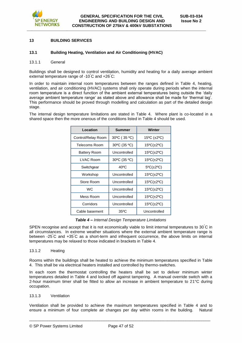
GENERAL SPECIFICATION FOR THE CIVIL ENGINEERING AND BUILDING DESIGN AND
CONSTRUCTION OF 275kV & 400kV SUBSTATIONS
SUB-03-034 Issue No 2
________________________________________________________________________________
© SP Power Systems Limited Page 47 of 52
13 BUILDING SERVICES
13.1 Building Heating, Ventilation and Air Conditioning (HVAC)
13.1.1 General
Buildings shall be designed to control ventilation, humidity and heating for a daily average ambient external temperature range of -10
°C and +26
°C:
In order to maintain internal room temperatures between the ranges defined in Table 4, heating, ventilation, and air conditioning (HVAC) systems shall only operate during periods when the internal room temperature is a direct function of the ambient external temperatures being outside the ‘daily average ambient temperature range’ as stated above and allowance shall be made for ‘thermal lag’. This performance should be proved through modelling and calculation as part of the detailed design stage.
The internal design temperature limitations are stated in Table 4. Where plant is co-located in a shared space then the more onerous of the conditions listed in Table 4 should be used.
Location Summer Winter
Control/Relay Room 30ºC ( 35 ºC) 15ºC (±2ºC)
Telecoms Room 30ºC (35 ºC) 15ºC(±2ºC)
Battery Room Uncontrolled 15ºC(±2ºC)
LVAC Room 30ºC (35 ºC) 15ºC(±2ºC)
Switchgear 40ºC 5ºC(±2ºC)
Workshop Uncontrolled 15ºC(±2ºC)
Store Room Uncontrolled 15ºC(±2ºC)
WC Uncontrolled 15ºC(±2ºC)
Mess Room Uncontrolled 15ºC(±2ºC)
Corridors Uncontrolled 15ºC(±2ºC)
Cable basement 35ºC Uncontrolled
Table 4 – Internal Design Temperature Limitations
SPEN recognise and accept that it is not economically viable to limit internal temperatures to 30°C in
all circumstances. In extreme weather situations where the external ambient temperature range is between -25
°C and +35
°C as a short-term and infrequent occurrence, the above limits on internal
temperatures may be relaxed to those indicated in brackets in Table 4.
13.1.2 Heating
Rooms within the buildings shall be heated to achieve the minimum temperatures specified in Table 4. This shall be via electrical heaters installed and controlled by thermo-switches.
In each room the thermostat controlling the heaters shall be set to deliver minimum winter temperatures detailed in Table 4 and locked off against tampering. A manual override switch with a 2-hour maximum timer shall be fitted to allow an increase in ambient temperature to 21°C during occupation.
13.1.3 Ventilation
Ventilation shall be provided to achieve the maximum temperatures specified in Table 4 and to ensure a minimum of four complete air changes per day within rooms in the building. Natural

GENERAL SPECIFICATION FOR THE CIVIL ENGINEERING AND BUILDING DESIGN AND
CONSTRUCTION OF 275kV & 400kV SUBSTATIONS
SUB-03-034 Issue No 2
________________________________________________________________________________
© SP Power Systems Limited Page 48 of 52
ventilation should be used whenever possible. Mechanical extract ventilation should be provided in the Mess Areas and WC’s, in accordance with Building Regulations. Within the switch halls of GIS Buildings ventilation shall be by means of high level fixed louvres with fly screens provided at both ends of the room unless the Constructor’s design demonstrates to SPEN’s satisfaction that either more or none at all is necessary.
13.1.4 Humidity
Humidity must be controlled to ensure the safe, efficient operation of the substation and to prevent any undue deterioration of the plant, equipment or fabric of the enclosure, in particular to prevent problems associated with condensation, typically by providing dehumidification or alternative natural air flow across the room from low to high-level through outside walls.
Relative humidity shall be maintained between 20% and 75%. Control of relative humidity is to be done by means of natural ventilation, wherever possibly (a minimum of four complete air changes per day to unsealed rooms is required).
13.1.4.1 Humidity control by dehumidification
Where utilised, dehumidifiers shall be high-level wall-mounted units capable of efficient operation between the temperature range of +5
°C and +30
°C. Discharge pipes shall be taken directly through
walls at high-level to drop externally within robust vandal and corrosion resistant protective downpipes to safely condensate and discharge at ground level. Low loss trace heating shall be provided on the dehumidifier drain.
Rooms utilising dehumidification shall be draught-sealed and shall not incorporate ventilation units.
The dehumidifier drying cycle shall be controlled by a humidistat, suitably located away from the dehumidifier airflow but forming an integral part of the unit. The switching point shall be capable of being set over the range of 40% to 80%, but factory set at 50%.
A second humidistat shall be provided in a similar position for use as a high relative humidity (RH) level alarm, which shall be pre-set at 70% and factory sealed. The auxiliary contacts of this humidistat shall be set to open at 70% RH and above, such that when the level is below 70% RH the auxiliary contacts are closed, giving a constant healthy signal to the SCADA system. The contact ratings shall be suitable to meet the rating of the dehumidifier.
Both humidistats shall be clearly labelled to indicate their function and RH level setting range.
The refrigerant shall be CFC free.
The defrosting cycle shall be controlled primarily by an auto-defrost device of the temperature sensing type.
13.1.4.2 Dehumidifier Design Note:
Dehumidification shall be capable of extracting at least 75ml/hr of moisture from the sealed room environment at 10
oC / 50% (RH) – more than one unit may be required per room. The following
conditions shall be assumed:
Ambient humidity 80%RH;
Ambient temperature +20°C;
Design humidity 50%RH.
13.1.4.3 Humidity control by ventilation
Where it is proposed to control humidity by means of natural ventilation this shall achieve a minimum of four complete air changes per day to unsealed (non-dehumidified) rooms and there should be a minimum 1m clear external to walls incorporating ventilation units. These walls shall be located such that they are adequately clear of areas that may be a fire risk, be dusty or have potentially hazardous gas or chemicals in the air.

GENERAL SPECIFICATION FOR THE CIVIL ENGINEERING AND BUILDING DESIGN AND
CONSTRUCTION OF 275kV & 400kV SUBSTATIONS
SUB-03-034 Issue No 2
________________________________________________________________________________
© SP Power Systems Limited Page 49 of 52
Ventilation units shall be of robust vandal and corrosion resistant construction such as masonry air bricks or galvanised steel louvres.
Ventilation units shall be secure and weathered to offer appropriate protection against moisture ingress and shall incorporate appropriate seals to the external perimeter. They shall conform to BS EN 13030 and provide a discharge loss coefficient of Class 2, a water repellent classification of Class A and a classification of A3 up to 0.5m/s.
Furthermore, the construction of these ventilation units shall be such that long object probes of any type and cross-section do not have the potential to infringe safety clearance distances from hazardous parts.
Intumescent ventilation units shall be used where segregation in the event of fire is required.
Substation enclosures shall not have windows.
13.1.5 Battery rooms
Ambient temperature to bespoke Battery Rooms shall be controlled such that it is maintained within the manufacturer’s recommended upper and lower limits for optimum performance and lifespan, however, wherever practical the use of air conditioning schemes shall be avoided
Where a separate battery room is required, to house vented unsealed cell batteries, natural ventilation only shall be provided to Battery Rooms with designed such that these rooms are not designated as hazardous areas under applicable BSEN specifications. Overall substation design shall be such that services passing through internal substation walls to these Battery Rooms are kept to an essential minimum and, in addition to fire-stop requirements seals shall be durable and gas-tight.
13.1.6 Insulation
Buildings shall be capable of achieving sufficient thermal insulation as necessary to provide an appropriate internal environment and avoid moisture ingress via condensation. In particular buildings shall provide, as a minimum standard, thermal transmittance U Values as detailed in Table 5. There is no requirement for insulation in cable basements.
Region Roof
U (W/m²K) Walls
U (W/m²K) Floor
U (W/m²K)
Scotland 0.2 0.27 0.22
England & Wales 0.25 0.35 0.25
Table 5 – Thermal Insulation Requirements
13.2 Building Electrical Systems
13.2.1 General
Electrical installation schemes shall be entirely suitable to the intended purpose of each room within buildings, including LV AC supply distribution board and if applicable design to satisfy requirements for use in potentially explosive environments in Battery Rooms with unsealed batteries. These schemes shall conform in all respects to the requirements of the relevant BS/BSEN Standards and the Regulations for the Electrical Equipment of Buildings issued by the Institution of Electrical Engineers (IEE) or its successor organisation. In addition, lighting design shall be in accordance with BS EN 12464-1.
The Constructor shall submit his proposals to SPEN for acceptance prior to commencing work, including loading calculations to verify the design for all aspects of the works.
The Constructor shall make available for inspection a valid electrical test certificate for the works in accordance with the current IEE regulations. These should be included, where applicable, within the CDM H&S File that is handed over to SPEN.
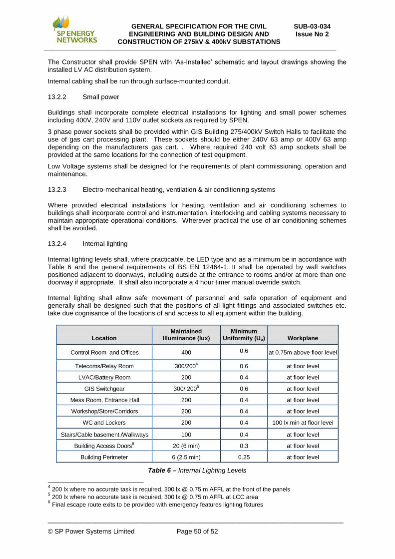
GENERAL SPECIFICATION FOR THE CIVIL ENGINEERING AND BUILDING DESIGN AND
CONSTRUCTION OF 275kV & 400kV SUBSTATIONS
SUB-03-034 Issue No 2
________________________________________________________________________________
© SP Power Systems Limited Page 50 of 52
The Constructor shall provide SPEN with ‘As-Installed’ schematic and layout drawings showing the installed LV AC distribution system.
Internal cabling shall be run through surface-mounted conduit.
13.2.2 Small power
Buildings shall incorporate complete electrical installations for lighting and small power schemes including 400V, 240V and 110V outlet sockets as required by SPEN.
3 phase power sockets shall be provided within GIS Building 275/400kV Switch Halls to facilitate the use of gas cart processing plant. These sockets should be either 240V 63 amp or 400V 63 amp depending on the manufacturers gas cart. . Where required 240 volt 63 amp sockets shall be provided at the same locations for the connection of test equipment.
Low Voltage systems shall be designed for the requirements of plant commissioning, operation and maintenance.
13.2.3 Electro-mechanical heating, ventilation & air conditioning systems
Where provided electrical installations for heating, ventilation and air conditioning schemes to buildings shall incorporate control and instrumentation, interlocking and cabling systems necessary to maintain appropriate operational conditions. Wherever practical the use of air conditioning schemes shall be avoided.
13.2.4 Internal lighting
Internal lighting levels shall, where practicable, be LED type and as a minimum be in accordance with Table 6 and the general requirements of BS EN 12464-1. It shall be operated by wall switches positioned adjacent to doorways, including outside at the entrance to rooms and/or at more than one doorway if appropriate. It shall also incorporate a 4 hour timer manual override switch.
Internal lighting shall allow safe movement of personnel and safe operation of equipment and generally shall be designed such that the positions of all light fittings and associated switches etc. take due cognisance of the locations of and access to all equipment within the building.
Location Maintained
Illuminance (lux) Minimum
Uniformity (Uo) Workplane
Control Room and Offices 400 0.6 at 0.75m above floor level
Telecoms/Relay Room 300/2004 0.6 at floor level
LVAC/Battery Room 200 0.4 at floor level
GIS Switchgear 300/ 2005 0.6 at floor level
Mess Room, Entrance Hall 200 0.4 at floor level
Workshop/Store/Corridors 200 0.4 at floor level
WC and Lockers 200 0.4 100 lx min at floor level
Stairs/Cable basement,/Walkways 100 0.4 at floor level
Building Access Doors6 20 (6 min) 0.3 at floor level
Building Perimeter 6 (2.5 min) 0.25 at floor level
Table 6 – Internal Lighting Levels
4 200 lx where no accurate task is required, 300 lx @ 0.75 m AFFL at the front of the panels
5 200 lx where no accurate task is required, 300 lx @ 0.75 m AFFL at LCC area
6 Final escape route exits to be provided with emergency features lighting fixtures

GENERAL SPECIFICATION FOR THE CIVIL ENGINEERING AND BUILDING DESIGN AND
CONSTRUCTION OF 275kV & 400kV SUBSTATIONS
SUB-03-034 Issue No 2
________________________________________________________________________________
© SP Power Systems Limited Page 51 of 52
Emergency lighting shall also be provided in accordance with BS 5266: Part 1. A key test wall switch shall be installed adjacent to the entrance door.
For lighting calculations purposes, a maintenance plan method with a maintenance factor of 0.67, corresponding to a clean room 3 years maintenance cycle, shall be used. Room surfaces reflections are considered as follows: Ceiling 0.7, Walls 0.5, Floor 0.2.
13.2.5 Exterior Lighting
Exterior lighting shall allow safe access and emergency egress for personnel (including from buildings) and safe operation of equipment, subject to the following minimum requirements:
Maintained average illuminance 6.0 lux at ground level;
Minimum maintained point illuminance 2.5 lux at ground level.
Where SPEN expressly require frequent access to or increased security lighting within compounds containing Outdoor Equipment these levels shall be increased locally to an average of 100 lux and minimum of 50 lux respectively.
Lighting columns shall be bolted to their foundations and designed to be lowered for maintenance by one person. Lighting columns shall be sized and positioned such that they cannot fall onto High Voltage Equipment. Luminaires shall, where practicable, be LED type with directable light output to minimise light pollution. Earthing of lighting columns shall be the Constructor’s responsibility.
Exterior lighting to buildings shall incorporate IP 65 wall mounted LED luminaires to illuminate all pathways surrounding the building, and shall be controlled via integral PIR detectors (minimum detection range of 12m and minimum detection angle of 110 degrees).
An internal wall mounted manual override switch, with a 4 hour maximum timer, shall be fitted adjacent to the main entrance/exit door to allow control of external lights, when required.. Note that a non-maintained IP 65 emergency bulkhead LED luminaire shall be mounted above each emergency exit doors.
13.3 Security alarm systems
Buildings shall incorporate security alarm systems to ScottishPower Corporate specification (available from SPEN) that are connected and commissioned to the substation local alarm and S.C.A.D.A. system for remote alarm indication. All cabling and connection to power shall be the Constructor’s responsibility but connection/commissioning of alarms to S.C.A.D.A. shall be by SPEN.
The security system operating panel shall be located adjacent to the main access door.
13.4 Fire alarm systems
Where Section 10.3.5 – ‘Fire Risk’ highlights the requirement for a fire alarm system within the building it shall be installed to the ScottishPower Corporate Specification (available from SPEN), connected and commissioned to the substation local alarm and S.C.A.D.A. system for remote alarm indication. All cabling and connection to power shall be the Constructor’s responsibility but connection/commissioning of alarms to S.C.A.D.A. shall be by SPEN.

GENERAL SPECIFICATION FOR THE CIVIL ENGINEERING AND BUILDING DESIGN AND
CONSTRUCTION OF 275kV & 400kV SUBSTATIONS
SUB-03-034 Issue No 2
________________________________________________________________________________
© SP Power Systems Limited Page 52 of 52
14 POST-COMMISSIONING (RETURN) SITE VISIT
Programming is outside the scope of this document but Constructors shall note for information that civil works return visits to sites are necessary anything between one and twelve months after substantial completion (i.e. after handover for equipment installation) to complete post-commissioning finishing civil and building works that may include but may not be exclusively limited to:
Sealing cable entries against moisture and vermin entry where this has not otherwise been completed as part of equipment installation and commissioning works;
Making-good original decoration within buildings where this has been damaged during installation of Equipment;
Making-up ground levels as necessary and stone chipping topping or other agreed finishes to compounds;
Sand/geotextile or other agreed protection to cables and stone chipping infill to Transformer bunds;
Kerbs, bituminous surfacing and drainage to internal roadways.
Where the substation has become operational under SPEN Safety Rules all Constructor operatives subsequently working at the substation shall have appropriate Scottish Power Authorisation(s)