General Rescue Manual - Ministry of Civil Defence and Emergency
130
General Rescue Manual March 2006
Transcript of General Rescue Manual - Ministry of Civil Defence and Emergency

General Rescue ManualMarch 2006


Table of contents
General Rescue Manual – March 2006 i
Table of contents 1 Introduction.................................................................................................. 1 1.1 Purpose ......................................................................................................... 1 1.2 Definition of USAR......................................................................................... 1
2 General rescue background........................................................................ 3 2.1 Objectives ...................................................................................................... 3 2.2 The aim of rescue .......................................................................................... 3 2.3 Functions ....................................................................................................... 3 2.4 The psychology of rescue .............................................................................. 3 2.5 Rescue workers ............................................................................................. 4 2.6 Personal traits of the rescue worker............................................................... 5 2.7 Personal behaviour ........................................................................................ 6 2.8 Team composition.......................................................................................... 6 2.9 Activation ....................................................................................................... 7 2.10 Deployment.................................................................................................... 7
3 Safety in training and operations ............................................................... 8 3.1 Objectives ...................................................................................................... 8 3.2 Introduction .................................................................................................... 8 3.3 The responsibility for safety ........................................................................... 8 3.4 Strategies to improve safety .......................................................................... 9 3.5 Basic precautions......................................................................................... 10 3.6 Personal protective equipment (PPE) .......................................................... 10 3.7 Rescue fall protection .................................................................................. 11 3.8 Casualty safety ............................................................................................ 12 3.9 Confined space operations .......................................................................... 12 3.10 Moving in an unknown environment............................................................. 13 3.11 Searching a darkened room......................................................................... 14 3.12 Moving on stairs........................................................................................... 15 3.13 Vehicle safety............................................................................................... 15 3.14 Equipment safety ......................................................................................... 15 3.15 Public utility hazards .................................................................................... 16 3.16 Correct lifting techniques ............................................................................. 16 3.17 Team lifting .................................................................................................. 17 3.18 Warning signals ........................................................................................... 17
4 Incident ground actions ............................................................................ 19 4.1 Objectives .................................................................................................... 19 4.2 Incident management .................................................................................. 19 4.3 Initial action strategies ................................................................................. 20 4.4 Site control ................................................................................................... 20 4.5 Rescue by stages ........................................................................................ 25

Table of contents
ii General Rescue Manual - March 2006
4.6 Continuing action ......................................................................................... 28 4.7 Precautions in operations ............................................................................ 28 4.8 Crush injuries ............................................................................................... 29 4.9 Debris clearance .......................................................................................... 29 4.10 When debris clearance is necessary ........................................................... 30 4.11 Methods of debris clearance........................................................................ 30 4.12 Precautions in operations ............................................................................ 30 4.13 The appreciation process............................................................................. 31 4.14 Introduction to Search and Victim Marking .................................................. 32 4.15 Disaster victim identification (DVI) ............................................................... 34 4.16 Suspicious circumstances............................................................................ 34 4.17 Conduct at the scene ................................................................................... 34
5 Ropes.......................................................................................................... 36 5.1 Objectives .................................................................................................... 36 5.2 Introduction .................................................................................................. 36 5.3 Types of rope............................................................................................... 36 5.4 Synthetic ropes ............................................................................................ 37 5.5 Kernmantle Construction ............................................................................. 37 5.6 Characteristics of Static Kernmantle Rope .................................................. 38 5.7 Characteristics of rescue ropes.................................................................... 38 5.8 Breaking force.............................................................................................. 39 5.9 Safe working load (SWL) ............................................................................. 39 5.10 Care and maintenance................................................................................. 39 5.11 Washing ropes ............................................................................................. 40 5.12 Inspection .................................................................................................... 40 5.13 Retiring a rope ............................................................................................. 41 5.14 Terminology ................................................................................................. 42 5.15 Rope packaging ........................................................................................... 43 5.16 Identification................................................................................................. 44 5.17 Record systems ........................................................................................... 44 5.18 Climbing tapes ............................................................................................. 45 5.19 Construction................................................................................................. 45 5.20 Size.............................................................................................................. 46 5.21 Abrasion....................................................................................................... 46 5.22 Tape strength............................................................................................... 46 5.23 The use of tape............................................................................................ 46 5.24 Care and maintenance................................................................................. 47 5.25 Safety........................................................................................................... 47 5.26 Flexible steel wire rope ................................................................................ 47 5.27 Safe working load (SWL) ............................................................................. 47 5.28 Construction................................................................................................. 48 5.29 Precautions in operations ............................................................................ 48 5.30 Inspection of steel wire rope ........................................................................ 48

Table of contents
General Rescue Manual – March 2006 iii
5.31 Storage of steel wire ropes .......................................................................... 49
6 Knots........................................................................................................... 50 6.1 Objectives .................................................................................................... 50 6.2 Introduction .................................................................................................. 50 6.3 Stopper knots............................................................................................... 50 6.4 Figure 8 knots .............................................................................................. 50 6.5 Figure 8 knot (Single figure 8)...................................................................... 51 6.6 Figure 8 on a bight (Double figure 8) ........................................................... 51 6.7 Rethreaded figure 8 ..................................................................................... 51 6.8 Figure 8 joining knot (Figure 8 bend) ........................................................... 52 6.9 Double figure 8 on a bight (Anchor 8 or Industrial 8).................................... 53 6.10 Round turn and two half hitches................................................................... 53 6.11 Alpine butterfly ............................................................................................. 54 6.12 Double fisherman’s knot .............................................................................. 54 6.13 Prusik knot ................................................................................................... 55 6.14 Clove hitch ................................................................................................... 55 6.15 Friction hitch................................................................................................. 56 6.16 Joining ropes................................................................................................ 56
7 Ladders....................................................................................................... 57 7.1 Objectives .................................................................................................... 57 7.2 Introduction .................................................................................................. 57 7.3 Construction................................................................................................. 57 7.4 Terminology ................................................................................................. 58 7.5 Extension ladders ........................................................................................ 59 7.6 Step ladders................................................................................................. 59 7.7 Inspection of ladders.................................................................................... 60 7.8 Maintenance of ladders................................................................................ 60 7.9 Single rescuer ladder raise .......................................................................... 60 7.10 Erecting and extending the ladder (2 rescuer) ............................................. 61 7.11 Erecting and extending the ladder (3 rescuer) ............................................. 61 7.12 Angle of ladder when raised ........................................................................ 62 7.13 Overlaps ...................................................................................................... 63 7.14 Securing ladders .......................................................................................... 63 7.15 Securing the head of the ladder ................................................................... 63 7.16 Securing the foot of the ladder ..................................................................... 63 7.17 Halving ladders ............................................................................................ 64 7.18 Ladder climbing............................................................................................ 64 7.19 Rules of 3..................................................................................................... 65 7.20 Helping a casualty down a ladder ................................................................ 65
8 Managing casualties.................................................................................. 66 8.1 Objectives .................................................................................................... 66

Table of contents
iv General Rescue Manual - March 2006
8.2 Introduction .................................................................................................. 66 8.3 START ......................................................................................................... 66 8.4 Labelling ...................................................................................................... 67 8.5 Consumer Code of Rights- Health and Disability Commission .................... 68
9 Stretchers ................................................................................................... 69 9.1 Objectives .................................................................................................... 69 9.2 Introduction .................................................................................................. 69 9.3 Folding or pole stretchers ............................................................................ 69 9.4 Board rescue stretchers............................................................................... 70 9.5 Basket stretchers ......................................................................................... 71 9.6 Wrap-around stretchers ............................................................................... 71 9.7 Blanketing the stretcher ............................................................................... 72 9.8 Blanketing - Lateral/Recovery position......................................................... 72 9.9 Loading the stretcher ................................................................................... 73 9.10 The four rescuer method.............................................................................. 73 9.11 Blanket lift (four or six rescuers)................................................................... 74 9.12 Clothing lift (Three rescuers)........................................................................ 75 9.13 Webbing bands (Five rescuers) ................................................................... 75 9.14 Specialist lifting/loading devices................................................................... 76 9.15 Summary of stretcher types and uses.......................................................... 76 9.16 Lashing the casualty to the stretcher ........................................................... 76 9.17 Lashing the folding stretcher........................................................................ 77 9.18 Lashing - Lateral/Recovery position............................................................. 77 9.19 Lashing - Board rescue stretcher ................................................................. 78 9.20 Alternate Board rescue stretcher lashing ..................................................... 78 9.21 Securing a basket stretcher with securing straps......................................... 79 9.22 Securing a basket stretcher by lashing ........................................................ 79 9.23 Improvised casualty harness ....................................................................... 80 9.24 Moving a stretcher over uneven ground....................................................... 80 9.25 Moving a stretcher in restricted spaces........................................................ 81 9.26 Improvised stretchers................................................................................... 82
10 Stretcher based rescue techniques ......................................................... 84 10.1 Objectives .................................................................................................... 84 10.2 Introduction .................................................................................................. 84 10.3 Definitions .................................................................................................... 84 10.4 Additional equipment ................................................................................... 85 10.5 Low angle rescue techniques ...................................................................... 85 10.6 Attachment of the line .................................................................................. 85 10.7 Creation of the friction/“catch” ...................................................................... 87 10.8 Limited High angle rescue techniques ......................................................... 87 10.9 Guide lines................................................................................................... 88 10.10 Single point lower......................................................................................... 88

Table of contents
General Rescue Manual – March 2006 v
10.11 Two point lower............................................................................................ 89 10.12 Four point lower ........................................................................................... 90 10.13 Ladder Slide................................................................................................. 91 10.14 Ladder Hinge ............................................................................................... 93
11 Non-stretcher based rescue techniques.................................................. 94 11.1 Objectives .................................................................................................... 94 11.2 Introduction .................................................................................................. 94 11.3 Vertical Lift Knot........................................................................................... 95
12 Improvised casualty movement................................................................ 96 12.1 Objectives: ................................................................................................... 96 12.2 Introduction .................................................................................................. 96 12.3 One rescuer techniques............................................................................... 96 12.4 Two rescuer techniques............................................................................... 98
13 Anchors and holdfasts .............................................................................100 13.1 Objectives ...................................................................................................100 13.2 Introduction .................................................................................................100 13.3 Natural anchors...........................................................................................100 13.4 Constructed anchors...................................................................................100 13.5 Improvised anchors.....................................................................................103 13.6 Precautions in operations ...........................................................................103 13.7 Selection of anchors ...................................................................................103 13.8 Sling loading angles....................................................................................104 13.9 Attachment to anchors ................................................................................105 13.10 Safety summary ..........................................................................................106
14 Pulley systems and lifting........................................................................107 14.1 Objectives ...................................................................................................107 14.2 Introduction .................................................................................................107 14.3 Terminology ................................................................................................107 14.4 Types of pulleys ..........................................................................................108 14.5 Characteristics of the lightweight rescue pulley ..........................................108 14.6 Constructing pulley systems .......................................................................109 14.7 Types of pulley systems..............................................................................109 14.8 Mechanical advantage ................................................................................109 14.9 Precautions in use ......................................................................................110 14.10 Lift/Lower rope rescue devices ...................................................................110 14.11 Commercial pulley systems ........................................................................111 14.12 Drum systems.............................................................................................111 14.13 Standard procedures for use ......................................................................111 14.14 Levers .........................................................................................................112 14.15 Fulcrum blocks............................................................................................112 14.16 Lifting ..........................................................................................................112

Table of contents
vi General Rescue Manual - March 2006
15 Additional general rescue equipment .....................................................113 15.1 Objectives ...................................................................................................113 15.2 Introduction .................................................................................................113 15.3 Karabiners ..................................................................................................113 15.4 Accidental gate opening..............................................................................114 15.5 Concerns with screwgate karabiners ..........................................................114 15.6 Karabiner usage..........................................................................................114 15.7 Shackles .....................................................................................................115 15.8 Safety in operation ......................................................................................115 15.9 Generators..................................................................................................115 15.10 ELCB’S and RCD’S ....................................................................................116 15.11 Power output of the generator ....................................................................116 15.12 Precautions in operations ...........................................................................117 15.13 Electrical safety precautions .......................................................................117 15.14 Generator maintenance and regular checks ...............................................118 15.15 Generator storage.......................................................................................118 15.16 Lighting .......................................................................................................119 15.17 Positioning lighting ......................................................................................119

Section 1: Introduction
General Rescue Manual – March 2006 1
1 Introduction
1.1 Purpose The purpose of the General Rescue Manual is to provide guidelines for standard methods of training for General Rescue techniques in New Zealand. It is written to accompany the USAR Awareness Student Manual and reference to this manual is made frequently. The development of the USAR structure in New Zealand has provided the impetus for the review in 2004 of the General Rescue Manual. This, with an increased emphasis on safety, has meant some techniques have been modified, others deleted or replaced. Interestingly, some of the core skills developed over the years in New Zealand have stood the test of time and are a credit to the pioneers of general rescue in New Zealand. USAR Awareness and General Rescue combine to provide rescue workers with a range of core skills to safely and effectively locate, extract and rescue victims from a variety of events. It is not intended to be exhaustive, but rather provide a framework for the development of individual rescue workers, and ultimately rescue teams. NOTE: This manual has been developed to support and accompany practical
training sessions delivered by suitably qualified trainers.
1.2 Definition of USAR An integrated multi agency response which is beyond the capability of normal rescue arrangements, to provide initial medical care and removal of entrapped persons from damaged structures or other environments in a safe and expeditious manner. New Zealand has made some significant steps in the development of the USAR structure in recent years. The USAR Awareness Manual covers more about the history and structure of USAR in New Zealand, but of particular note are:
• The USAR Tier System • The Responder certification (Orange Card) • USAR Registered Response Teams and USAR Taskforces.
Individuals receive Responder certification, and an Orange Card when they have completed recognised, unit standard based training in USAR Awareness, the Co-ordinated Incident Management System (CIMS), First Aid and General Rescue. A USAR Awareness course should, in most cases, be completed in conjunction with training in General Rescue.

Section 1: Introduction
2 General Rescue Manual – March 2006
A Registered New Zealand Response Team is a team of people who have a collective level of skill (based on Responder certification) have met the minimum equipment requirements and have Standard Operating Procedures. A USAR Taskforce is a national team of Taskforce Technicians plus support and specialists. A Task Force Technician is a person trained to carry out specialist structural collapse rescue. More information on USAR Responders, Technicians and Specialists can be found by visiting www.usar.govt.nz.

Section 2: General rescue background
General Rescue Manual – March 2006 3
2 General rescue background
2.1 Objectives On completion of study and/or instruction on this chapter of the General Rescue Manual individuals:
should know: • The aim of rescue
and demonstrate awareness of:
• the 3 categories of rescue workers • personal traits of the rescue worker • some important areas of personal behaviour related to rescue
2.2 The aim of rescue To save the greatest number of lives in the shortest possible time and to minimise further injury to people and damage to property.
2.3 Functions Common rescue functions include:
• Access to, and the support and removal of, trapped people in the course of rescue operations.
• Assistance with the recovery of the dead (managed and conducted by NZ Police).
• Provision of support on request to other services, authorities or specialist teams.
WARNING NOTE: In order to achieve the aim of rescue, all rescuers must be trained in
basic life sustaining first aid to recognised standards.
2.4 The psychology of rescue A moments reflection is all that is needed to realise that any situation requiring a rescue operation, by definition is one which contains either dangerous or potentially dangerous elements. People tend to react differently to danger, but the most general responses are anxiety and fear, perhaps the most powerful of all emotions. It must be remembered that it is not just the victim who faces the danger; in order to rescue the victim the rescuer must first enter the site of the dangerous situation and face the same danger.

Section 1: Introduction
4 General Rescue Manual – March 2006
Even if the main danger has struck and passed, additional dangers are still often present. The difference between the victim and the rescuer is that the rescuer is better able to cope with, or handle, the situation. This is because the rescuer has the knowledge and the resources to minimise risk and remedy the situation. It is normal to be anxious and feel fear in the face of danger. These are emotional reactions common to both victim and rescuer. Many other emotional responses may become manifest during a rescue situation - pity, disgust, contempt, pride, concern, and many more. These are often exaggerated beyond all reason by the urgency and pressures of the situation, thus lowering the efficiency of the overall operation. The rescuer must be aware of the psychological needs of the victims, not just their physical needs, and be prepared to meet these psychological needs.
2.5 Rescue workers An event requiring rescue operations will usually create three categories of rescue workers:
Category 1 – Survivors The immediate reaction of survivors in a major incident, once they have discovered that they are not injured, is to help their neighbours and families. They often do not know what to do, but obviously it is a serious situation and thus they feel they must do something. These good intentions could aggravate the conditions of those being ‘helped’ to the point where the loss of life may be greater than it should be. They could also get in the way and interrupt the functioning of trained rescue teams. However, uninjured and slightly injured survivors could well be the only hope of survival for many victims (e.g. if toxic gases, dangerous chemicals, fire, or danger of fire exist at the site of the emergency). The first group to commence rescue work at a site consists of those survivors still physically capable of doing so. The potential for good is enormous but the danger inherent in rescue work by untrained personnel is also enormous. Category 2 – Untrained personnel The second ‘wave’ of rescue workers is drawn from people either witnessing the event from the immediate vicinity, or are drawn to the site by curiosity and a desire to assist the victims. Although not quite as emotionally involved as the survivors, the danger inherent in utilising untrained personnel is still a factor which must be considered. On the positive side, they often bring necessary resources with them and can be effective if brought under control and properly supervised. Unfortunately, a large number of the ‘curious’ are just that. They have no desire to help, but just look. They get in the way, shout advice, and generally add to the excitement of the site – the very thing that is least needed, especially from the standpoint of victims.

Section 2: General rescue background
General Rescue Manual – March 2006 5
Category 3 – Trained personnel The last group to arrive at the scene is the trained rescuers: Police, Fire, Civil Defence, etc. It takes some time for various emergency services to mobilise and arrive at the scene. The quicker they can arrive, the less time there will have been for the first two groups to aggravate the situation and create more dangers to surviving victims and themselves. The well-trained team will know what to do, and how to utilise the available resources and untrained personnel in efficiently carrying out the necessary tasks in a manner that will not further endanger anyone. Note: Experience overseas shows that up to 80% of rescues are carried out by category 1 and 2 personnel. Category 3 personnel rescue 15% with the last 5% being rescued by highly trained specialist teams such as USAR Taskforces.
2.6 Personal traits of the rescue worker Rescue work is not an easy task, nor is it necessarily a ‘glamorous’ one. Certainly not all people are suited to such work. Physical fitness, personality, and emotional stability are all factors in determining one’s suitability. Ideally, the rescuer will have the following qualities:
• Interest- A genuine interest in rescue work, not just because of peer pressure, trying to impress etc.
• Training- The will to continually undergo training to maintain a professional standard.
• Cooperation- Rescue work is usually a team effort, hence cooperation with others is vital.
• Dependability- The lives of victims and team members rely on the rescuer. • Initiative- The nature of rescue operations is such that it is often impossible to
closely supervise each team member. Each must be able to see what needs doing, set priorities and do the tasks at hand.
• Versatility- Each situation is unique. An individual must be able to apply a wide range of skills and knowledge to new situations.
• Physical fitness- Rescue work of any kind is physically demanding and often continues for long periods. Any physical limitations must be recognised and taken into consideration.
• Leadership qualities- Required by all rescuers at various times and to varying degrees. Through the capable leadership of trained rescuers, many more untrained personnel may be utilised.
• Control over fears and phobias- It is important that rescuers know what they can and cannot do. Part of this knowledge consists of being aware of any phobias. It is also vital that the leader of a rescue team knows of any phobias in team members. Some phobias that could seriously affect a rescuer and which may be identified in training are:
o The fear of the sight of blood (Hemophobia) o The fear of heights (Acrophobia) o The fear of confined spaces (Claustrophobia)

Section 1: Introduction
6 General Rescue Manual – March 2006
o The fear of water (Hydrophobia) • Good dress and bearing- Appearance should instill confidence in others.
2.7 Personal behaviour The conduct of individuals says a lot about their psychological makeup and personality. The nature of rescue work is such that it is particularly important that personal conduct does not aggravate matters, but rather assists in creating a feeling that the situation is in competent hands, and everything possible is being done to rescue and care for the victims. Bad behavior by an individual, e.g. bad language, reflects negatively on the whole team and its leadership. A few of the more important general areas of conduct or behaviours follow:
• Attitude—A serious, professional attitude must be maintained to gain confidence and support. Arrogance and superiority create instant antagonism. Loud talking, joking, and horseplay reduce credibility; they create a feeling of resentment and disgust and add to the confusion, thus hindering the work and adding to the state of anxiety of the victims. Rescuers cannot consider themselves ‘professional’ if they add to the confusion by loud shouting or frantic gestures.
• Emotions—Emotions are hard to control in the best of circumstances. In a disaster the control of emotions is a very difficult task but every effort must be made to prevent emotions from influencing good judgement and competence. Regardless of the excitement and the severity of the incident, the rescuer must be able to remain calm, and be sympathetic without becoming emotionally involved.
• Courtesy—Courtesy, tact, and good judgement are vital if the rescue task is to be completed quickly and effectively. Courtesy must be given to all concerned.
• Confidentiality—During rescue activities and training there may be times when rescuers will see and hear things which will be deemed confidential. It is essential that they understand this, be ‘professional’ and do not discuss these matters with others.
A Code of Ethics for rescue workers is currently being developed by the International Search and Rescue Advisory Group (INSARAG) and when finalised should be used as a guiding document.
2.8 Team composition Team composition will be determined by the various organisations within each area on the basis of safe accomplishment of set tasks. Regardless of the team composition, a team leader must be appointed. A team of 6 – 8 members is required for effective general rescue teamwork. Teams may be larger, but these are often split into squads of 6-8 rescuers to allow them to be easily managed.

Section 2: General rescue background
General Rescue Manual – March 2006 7
2.9 Activation Each team should have a callout system established, and have determined the time necessary to ensure a full team response. This system should include such details as:
• Who calls out the team • Who will be responsible for them • Where to report • What functions the team will perform • What equipment to take • Likely duration of task or event.
2.10 Deployment On call-out, teams should clearly state to the organisation requesting their support details of accommodation and any feeding assistance that may be required. If practical, each team should be self-sufficient in the provision of food for the first 24 hours. Note: Minimum requirements for team number, structure, activation and deployment
are established for teams wanting to register as a New Zealand Response Team.

Section 3: Safety in training and operations
8 General Rescue Manual – March 2006
3 Safety in training and operations
3.1 Objectives On completion of study and/or instruction on this chapter of the General Rescue Manual individuals:
should know: • Who is responsible for safety at training and rescue operations
Demonstrate awareness of:
• Safe Person Concept or Risk Assessment Management System • Safe lifting techniques
Practically demonstrate a technique for, in an unknown environment:
• opening a door • climbing stairs • searching a darkened room
3.2 Introduction The task of rescue involves the training of individuals and teams in a variety of skills, some of which, unless properly carried out, may well prove dangerous to the individual rescuer, the team, casualties, or bystanders. In all cases, the safety of rescuers is of prime importance. It is therefore necessary, particularly in the early stages of training and exercises, to pay a great deal of attention to safety measures, and to emphasise the need to strictly observe and enforce these measures.
WARNING NOTE: All rescue training and operations must be carried out with due regard to safe work practices, occupational health and safety requirements, and
codes of practice and guidelines.
Many of the safety precautions to be observed are merely common sense. Unfortunately, they are so basic and simple they are often overlooked.
3.3 The responsibility for safety Safety is the principal consideration in any rescue activity and it is the responsibility of each rescuer to ensure that safety procedures and Occupational Health and Safety requirements are followed, instructions observed, and operations carried out with a minimum of risk.

Section 3: Safety in training and operations
General Rescue Manual – March 2006 9
There are a number of guidelines, codes of practice, regulations, and procedures that relate to safety, and to operational aspects such as critical incident stress, and risk management. These are constantly being amended and updated – it is the responsibility of organisations to keep their procedures and policies in line with the current guidelines, codes of practice and regulations. Reference to the most relevant of these are made throughout this manual, and were correct at the time of printing. Additionally, individual services have procedures for the management of these factors, and for determining individual and organisational responsibilities. All of these factors must be taken into account in the management of rescue activities. This section covers the key points of safety in training and operations as they affect the rescuer, the casualty, or the bystander. Specific safety points will be covered with each rescue technique, as they affect how the particular rescue technique is conducted.
3.4 Strategies to improve safety There are a number of strategies/systems that have been developed to improve the safety of rescue operations. No matter what system is used, the objectives are the same: Identify hazards and risks and take steps to:
• eliminate • isolate or • minimise the risk
For example: Risk Assessment Management System (RAMS) RAMS is a process where the activities planned to be undertaken are evaluated for their hazard/risk and the steps that can be taken to reduce the risk are identified in a systematic way. Safe Person Concept (SPC) The safe person concept provides a framework for the application of the risk assessment and management process. It is used extensively by the New Zealand Fire Service, and can easily be adapted for the general rescue environment. The SPC uses a 5-step risk assessment and review:
1. Identify potential hazards and risks 2. Likelihood - what is the likelihood of these occurring - certain, very likely,
unlikely or rare 3. Consequences - what are the likely consequences - catastrophic, major,
moderate or insignificant 4. Level of risk - what is the level of risk? Risk = likelihood x consequence 5. Actions - what actions can be taken to eliminate, isolate or minimise the risk.

Section 3: Safety in training and operations
10 General Rescue Manual – March 2006
This is often presented in a table: eg for General Rescue Training
Potential hazard
Likelihood (Certain, Very
Likely, Unlikely, Rare)
Consequences(catastrophic, Major,
Minimal, Low)
Level of risk (Extreme, High,
Mod, Low)
Actions to be taken
Rope breaking Rare Major Moderate All ropes used to meet standard (M) Only approved knots used (M)…
3.5 Basic precautions Safety Officers should be appointed for any rescue activity. Team Leaders and Safety Officers are responsible for safety at all times, but every team member needs to be aware of their responsibility to raise safety concerns at any time. The orders given by these officers are to be obeyed without question or delay, as they are vital to safety. In general, the Safety Officer should not undertake any other role - their focus is on safety. Equipment must be regularly and carefully checked both before and after use. Ropes can wear and rot, batteries can corrode equipment, and machinery can break down. Faulty equipment can cost lives. Any faulty or suspect equipment must be labeled immediately and removed for repair or replacement (e.g. the rope that a rescuer used, inadvertently damaged, but did not check, may kill someone next time it is used). Personnel ‘at risk’ by working at heights or depths must be protected by properly established and monitored safety lines and systems. Wherever possible, rescuers should adhere to standard techniques and practices. In any rescue technique, safety limits and margins have been built in for casualty and rescuer protection. These must never be ignored or exceeded.
WARNING NOTE: Under no circumstances is smoking permitted in the rescue environment.
3.6 Personal protective equipment (PPE) PPE should be issued/made available to each rescuer and is a key in ensuring the safety of rescue personnel.

Section 3: Safety in training and operations
General Rescue Manual – March 2006 11
The following is a list of basic PPE for rescue workers - consistent with USAR Awareness Student Manual:
• Helmet • Whistle • Full-length clothing • Headlamp • Torch • Goggles • Dust masks • Gloves • First aid kit • Knife or shears • Boots • Hearing protection • Knee and elbow pads (advised for USAR Awareness)
It is important that each piece of PPE is appropriate for the task being undertaken, and meets the appropriate AS/NZ or international standard. Helmets, in particular, must be worn at all times of risk, whether great or small. All safety equipment must be maintained and replaced in accordance with the manufacturer’s recommendations.
3.7 Rescue fall protection Rescue personnel who work in situations where they could fall three meters or more are required, under the Health and Safety in Employment Act 1992 to protect themselves from this potential fall. Consideration should also be given at heights of less than three meters if the result of the fall could lead to an injury. Personnel should wear a harness if there is a potential risk of falling. This harness should meet the requirements of AS/NZS 1891.1: 1985 Safety Belts and Harnesses or equivalent standard, and preferably be of the full body type. As there are many types of harnesses available including sit harnesses, fall arrest harnesses and rescue harnesses. Advice should be sought when deciding on what type of harness you require. Fall protection can be provided under two basic categories. The first of these is fall prevention where the person is restricted from gaining access to the edge where they could fall, i.e. guardrails or a length of line attached to an anchorage and the person’s harness which is short enough to stop them reaching the edge. The second method is fall arrest where some device is used to stop a person from hitting a lower surface after a fall i.e. using a shock absorbing lanyard or rope grabbing device.

Section 3: Safety in training and operations
12 General Rescue Manual – March 2006
For further information regarding safe work at height the Occupational Safety and Health Service’s Guidelines for the Prevention of Falls should be consulted.
3.8 Casualty safety The safety of casualties is very important. Every effort, including the use of protective equipment, must be made to ensure that casualties come to no further harm once a rescue team arrives at the scene.
WARNING NOTE: Horseplay or casual handling of casualties is unsafe and must not be
tolerated.
For the sake of realism in training it is an advantage to use live casualties in exercises and drills. Teams should bear in mind the added safety required when dealing with heights, water, and contaminated areas, where dummy casualties may be substituted. In most cases, it is only by handling live casualties in training and exercises that rescuers will appreciate the problems they will encounter on operations.
3.9 Confined space operations
WARNING NOTE: Confined spaces are very dangerous
Activities in a confined space must only be undertaken by appropriately trained and qualified personnel.
In rescue operations, many environments may fall within the definition of confined spaces as laid down in Standard ASNZ 2865:2001 (Safe Work in Confined Spaces). A confined space is defined as an enclosed or partially enclosed space which:
• Is at atmospheric pressure during occupancy
• Is not intended or designed primarily as a place of work
• May have restricted means for entry and exit
• May have an atmosphere which contains potentially harmful levels of contaminant
• Does not have a safe oxygen level
• May cause you to be buried. Rescue activities in such environments must be carried out with particular regard to the problems of breathing in dangerous atmospheres.
Section 3: Safety in training and operations
General Rescue Manual – March 2006 13
The RAPID® programme, has produced a self-paced training module for confined space awareness. RAPID is a join initiative of the Ministry of Civil Defence & Emergency Management (MCDEM) and the Local Government Industry Training Organisation (LGITO).
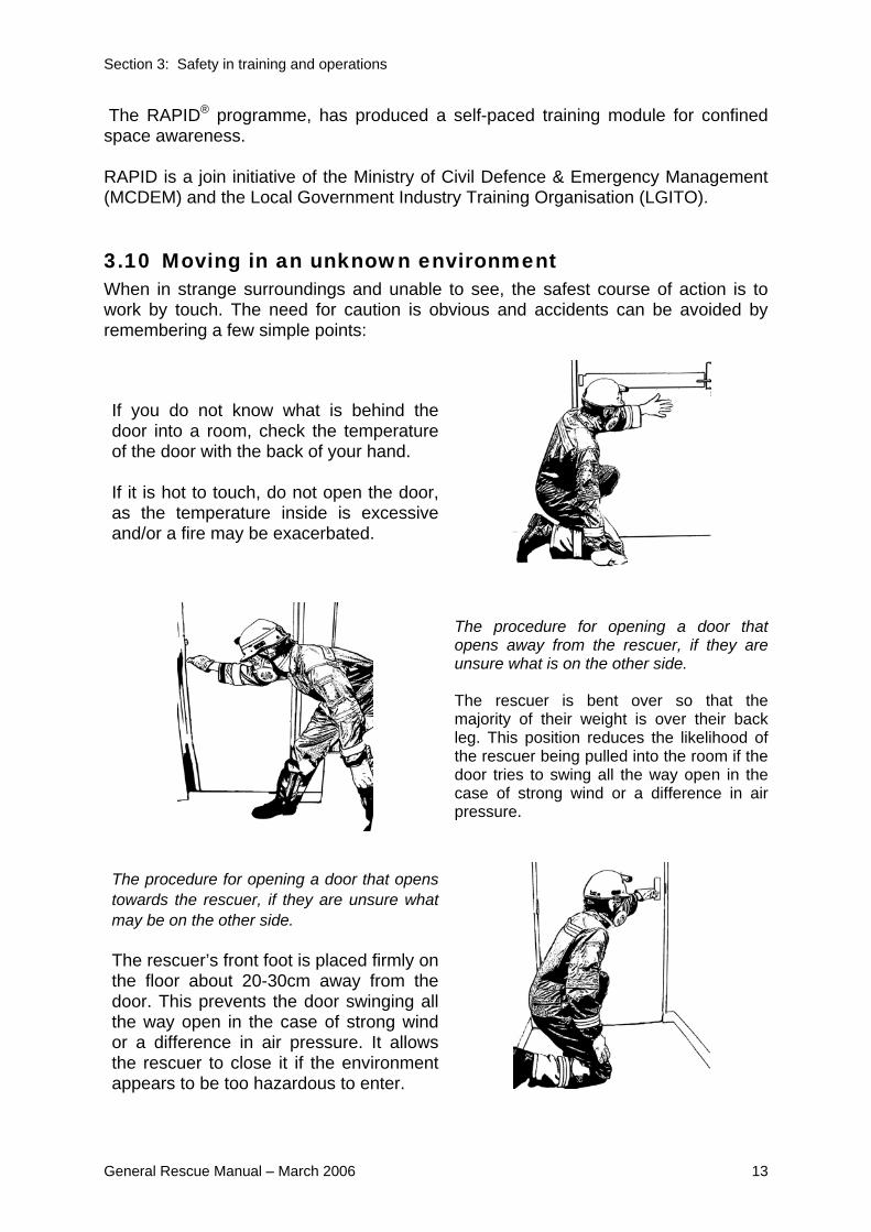
3.10 Moving in an unknown environment When in strange surroundings and unable to see, the safest course of action is to work by touch. The need for caution is obvious and accidents can be avoided by remembering a few simple points:
If you do not know what is behind the door into a room, check the temperature of the door with the back of your hand. If it is hot to touch, do not open the door, as the temperature inside is excessive and/or a fire may be exacerbated.
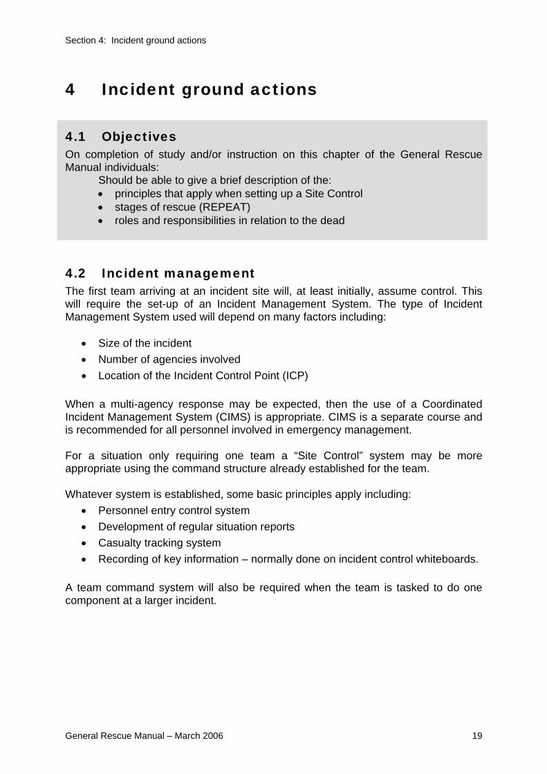
The procedure for opening a door that opens away from the rescuer, if they are unsure what is on the other side. The rescuer is bent over so that the majority of their weight is over their back leg. This position reduces the likelihood of the rescuer being pulled into the room if the door tries to swing all the way open in the case of strong wind or a difference in air pressure.
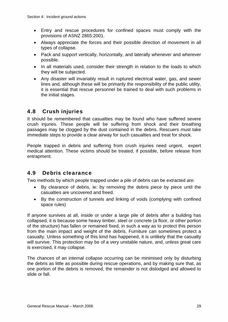
The procedure for opening a door that opens towards the rescuer, if they are unsure what may be on the other side. The rescuer’s front foot is placed firmly on the floor about 20-30cm away from the door. This prevents the door swinging all the way open in the case of strong wind or a difference in air pressure. It allows the rescuer to close it if the environment appears to be too hazardous to enter.

Section 3: Safety in training and operations
14 General Rescue Manual – March 2006
WARNING NOTE: Rescue workers should only enter smoke/dust filled room if required for
their evacuation from a building during an emergency situation.
If you need to leave a smoke-filled room, crawl on your hands and knees. In this position you are below dangerous heated gases and the bulk of the smoke. You will also be above toxic, heavier-than-air gases that may have been generated by burning plastics and natural materials.
If moving in upright position, shuffle, don’t walk. The weight of the body should be kept poised on the rear foot until the advancing foot has tested that it is safe to move forward; do not lift the feet from the ground – they should slide forward as this will help detect obstructions and dangers.
As you move forward raise your free hand in front of your face, lightly clenched, with the back uppermost, to feel for obstructions. If the back of your hand touches a live electric wire, shock will throw it clear. Your hand will not grasp the wire as it would if it were open.
3.11 Searching a darkened room Make a complete circuit of the room,
keeping close to the wall.
Feel under, and on, objects (beds, etc).
Open and feel inside cupboards, wardrobes, divans, and below other pieces of furniture
• If a complete circuit is made in this way, in an average sized room, there should be little danger of a victim being missed.
• As a final precaution, the room should be crossed diagonally to make sure that no-one is lying in the centre.
• In a larger open-plan area (office, etc.), adopt this method with diagonals to the centre of the room from each corner. Partitions and furniture will also hamper movement.

Section 3: Safety in training and operations
General Rescue Manual – March 2006 15
3.12 Moving on stairs When ascending or descending stairs, keep close to the wall, since the treads will usually bear weight at this point even though their centre may be weakened. It may be safer, particularly in darkened environments, to go down stairs backwards. This allows the rescuer to test the load bearing capacity of the next step before putting their full weight on it. If there is any doubt as to the strength of the stairs, allow only one person on each flight at any one time. The balustrade should be used with caution; it may have been weakened and may collapse if any weight is applied to it. If a stairway has been seriously damaged, use sections of extension ladders to improvise a stairway.
3.13 Vehicle safety Emergency vehicles must be driven by an authorised driver in accordance with the Road Transport Act, particularly with regard to the use of warning lights and sirens. Vehicles and trailers must be maintained in a road-worthy condition, and regular checks and inspections should be made. Upon arrival at an accident scene, the rescue vehicle must be positioned with due regard to the site hazards, and warning devices must be used to protect the team and the vehicle. The aim of a rescue team is to assist the public in time of need, and this should always be kept in mind when the team is traveling to an emergency. Little can be done for original casualties if the rescue team is involved in an accident en-route.
3.14 Equipment safety There is a range of equipment that may be appropriate for specific situations. All equipment should be used in close compliance with the manufacturers’ operating instructions, and the following basic safety rules for rescue tools and equipment should be followed:
• Safety goggles and gloves must be worn when using power tools or hammering pickets.
• Careful safety consideration must be given before any modification of equipment, or method of use, is attempted.
• Only blades, fuel, oil, hydraulic fluid, and parts that are recommended by the manufacturer should be used.
• Petrol driven motors must never be refueled while they are hot, and they must be kept apart from fuel supplies and casualties.
• All specific safety procedures for rescue equipment must be adhered to, and regular and careful safety checks must be carried out both before and after use.

Section 3: Safety in training and operations
16 General Rescue Manual – March 2006
3.15 Public utility hazards Public utility hazards pose a range of safety issues for rescuers. The following information is taken from the USAR Awareness Student Manual (pg 38):
The disruption of gas, water and power services will further complicate a rescue at a collapse incident. The escape of gas causes two areas of concern. The first is the displacement of oxygen in a confined space and the second the potential for an explosive mixture. With the displacement of oxygen, the victims and rescuers could be overcome by the lack of oxygen. Ventilation or the use of breathing apparatus will assist, but atmospheric monitoring is essential to ensure a safe working environment. If there is a risk of fire or explosion, cutting off the source of ignition and providing safe and effective ventilation can reduce this threat. Note: Constant monitoring of air quality throughout the rescue can reduce the likelihood of explosion that would cause further casualties and greater injury. Due to the additional weight and the possibility of trapped victims drowning, water used for fire fighting purposes or from a ruptured pipe must be kept to a minimum and not allowed to accumulate. Water soaked debris can also make manual removal efforts more demanding for rescuers. Gas and water meters operating can indicate if either hazard is leaking or flowing and are usually situated at an isolation point. In order to monitor Environment and Situational Hazards, a Safety Officer should be part of each rescue team. The Safety Officer’s duties include: • monitoring the scene for unsafe conditions and acts • warning team members of impending danger • ensuring crews are rotated as required • monitoring the location of the team and its mission
3.16 Correct lifting techniques At all levels of rescue and training operations, rescuers will be required to lift, haul or push loads, and must be trained to handle these tasks properly and safely where mechanical aids are not available or useable. As the thigh muscles are stronger than those of the arms, back, or abdomen, it follows that these are the muscles that should be used for safe lifting.

Section 3: Safety in training and operations
General Rescue Manual – March 2006 17
The sequence of actions for lifting a load is:
1. Assess need (is there another way?) 2. Assess ability- get help if necessary 3. Clear path 4. Extend before you bend 5. Keep back straight 6. Use legs 7. Keep load close
Don’t twist Don’t walk backwards Don’t step over things
Loads should be lowered in a reversal of the lifting techniques.
3.17 Team lifting Team lifting is carried out using the same individual techniques already described, but with team discipline and control.
• When the team is in position, the Team Leader, or when lifting a casualty, a rescuer at the head end, gives the preparatory order: PREPARE TO LIFT.
• Any rescuer not ready to lift must call: STOP, and the Team Leader/rescuer must wait until all is in order. In the absence of any such response, the Team Leader/rescuer will give the order: LIFT.
• On this command, all rescuers lift their portion of the load by the technique already described, slowly, and in unison.
• As with the individual technique, lowering a load is the reversal of the procedure with the Team Leader/rescuer using the commands: PREPARE TO LOWER, and LOWER.
3.18 Warning signals INSARAG have developed a series of internationally accepted signals for use in rescue operations – the signals detailed below are the same as those taught in USAR Awareness.

Section 3: Safety in training and operations
18 General Rescue Manual – March 2006
Action Required Signal Evacuate 3 short blasts
Cease operations 1 long blast
Resume operations 1 long blast, followed by 1 short
Signals can be given using portable air horns, vehicle horns and whistles. The evacuation signal should be relayed by members of the team to ensure that everyone has heard it. Note: ASTM Rope Rescue and other signal systems exist that conflict with the above.
Section 4: Incident ground actions
General Rescue Manual – March 2006 19
4 Incident ground actions
4.1 Objectives On completion of study and/or instruction on this chapter of the General Rescue Manual individuals: Should be able to give a brief description of the:
• principles that apply when setting up a Site Control • stages of rescue (REPEAT) • roles and responsibilities in relation to the dead
4.2 Incident management The first team arriving at an incident site will, at least initially, assume control. This will require the set-up of an Incident Management System. The type of Incident Management System used will depend on many factors including:
• Size of the incident • Number of agencies involved • Location of the Incident Control Point (ICP)
When a multi-agency response may be expected, then the use of a Coordinated Incident Management System (CIMS) is appropriate. CIMS is a separate course and is recommended for all personnel involved in emergency management. For a situation only requiring one team a “Site Control” system may be more appropriate using the command structure already established for the team. Whatever system is established, some basic principles apply including:
• Personnel entry control system • Development of regular situation reports • Casualty tracking system • Recording of key information – normally done on incident control whiteboards.
A team command system will also be required when the team is tasked to do one component at a larger incident.

Section 4: Incident ground actions
20 General Rescue Manual – March 2006
4.3 Initial action strategies Following the bombing of the Murrah Federal Building in Okalahoma City, a series of initial action strategies were developed. These need to be considered at the initial stage of the incident response:
• Constantly gather information • Set up communication quickly • Limit supervisory staff • Establish inventory control system • Centralise logistics • Determine length of incident
4.4 Site control Site control will be set up in a suitable area close to the event. The Site Control Area is a vital area to ensure the efficient and effective control and management of an event.
• Site Control can be set up anywhere where it is safe from the effects and influence of the event and it must be at an appropriate location to work from.
• Site Control will manage and control the personnel at the event site. • It will handle information flow both in and out of the event and take care of all
safety issues. • It will be responsible for situation reports being sent and received from the
Incident Control Point (ICP). • Site Control in general is responsible for the efficient running of the event site. • It is a good idea to cordon off the Site Control Area, make it visible, well
identified and easy to find. Identifying the Site Control Area well saves time for personal entering the event area. In any major event all actions taken at Site Control will be under the guidance of the Incident Controller (IC) who will be working to an Incident Action Plan, all instructions received from the ICP must be acted on. The only variation to this is if there is no ICP established, in that case the first to arrive at the event will be responsible to set up Site Control, secure the site and start on an initial Incident Action Plan.
4.4.1 Tasks required for setting up Site Control Safety Officer A Safety Officer must be appointed to take care of safety issues at an event.

Section 4: Incident ground actions
General Rescue Manual – March 2006 21
The Safety Officer will be responsible for all safety issues that may effect team members and casualties at the event site. This will include being responsible for checking on any movement of walls, rubble material etc, and looking out for hazards either present or evolving that could be a danger to personnel or casualties. The Safety Officer’s responsibility is the safety of all personnel and casualties at the event site and the Safety Officer must not get involved with other tasks such as rescue etc. Note: A Safety Officer may also be required at the Safe Forward Point and/or at
operational sites of teams. Information boards Sufficient information boards will be required to display all information such as: -
• Registration Information. • Situation Reports. • Reconnaissance Information. • Map. • Incident Action Plan.
Registration All personnel entering Site Control must be registered in and out and a permanent record kept. A record must be kept of team members entering the event scene as well. This is particularly important with team members entering into the danger areas of the event. Reconnaissance teams and rescue teams must be accounted for. The information required is: -
• Name of the person entering. • The team or organisation they belong to. • Time in. • The time they registered out of the Site Control Area.
Stipulate the importance to register in and out when leaving the site. Some form of registration may also happen at the Safe Forward Point. Situation reports Situation reports are a vital part of site control, they should be sent direct to the ICP on a regular basis. It is imperative that the ICP be kept informed about the status of the event. Requests for resources will be included in the situation reports and the reports should be done at fifteen-minute intervals, sooner if necessary.

Section 4: Incident ground actions
22 General Rescue Manual – March 2006
Only relevant information should be sent and the content of the reports documented. Any medium (radio, runner, phone etc) can be used to deliver reports. Situation reports will include: -
• The number of the report. • Information sent. • Time sent. • Method sent.
All incoming information from the recipient e.g. the ICP, must be documented. Reconnaissance Reconnaissance teams will be deployed and information gained will be recorded. This information will be used in the Incident Action Plan and all necessary relevant information relayed back to incident control. Record all relevant information on the map such as hazards encountered, location of found casualties, landmarks and any dangers. Record all relevant information on the information board and keep a permanent record as well. Map A map of the event area must be made. It must be precise and show as much detail as possible and highlight known features, landmarks and any other relevant information. It is also important to show where hazards are on the map and identify any other dangers that could affect both rescue team member and casualties. Show on the map the location of all known identified casualties and their condition, Green, Red, etc. This will save time for future teams going to rescue them. Add landmarks to the map, these will act as reference points for those entering the event. Highlight on the map the location where the Site Control has been set up and send a copy to the Safe Forward Point, this will aid personnel entering the event area to find the Site Control after deployment from the Safe Forward Point (SFP). Incident Action Plan (IAP) The plan to rescue the maximum number of casualties in the shortest possible time. If a team is the first to arrive at an event and the event is not under control from an ICP, the team will need to start to create an Incident Action Plan. The plan is based on information gathered from all sources since the onset of the event. The plan will be taken over by the Incident Controller as soon as an ICP has been established providing the size and nature of the event warrants it. Incident Control will be in operation at all major events.

Section 4: Incident ground actions
General Rescue Manual – March 2006 23
The plan will initially be oral instructions but as the management of the incident becomes organized, written plans will be created and administered by the Incident Management Team (IMT). The plan must be achievable and establish the incident objectives. The Incident Action Plan will: -
Describe the overall operational objectives and strategies Ensure continuity of control operations Provide for effective use of resources Identify total anticipated resources
Safe Forward Point (SFP) The Safe Forward Point is the area where arriving personal and equipment assemble before being deployed into the event proper. It is important to remember that registration in and out is done at both the Safe Forward Point and at Site Control. The Safe Forward Point will be established at a safe location near to the event. It may be inside or just outside the inner cordon. The primary function of the Safe Forward Point is a place where teams and resources will assemble safely at an event. Security will be undertaken at the Safe Forward Point and a safety officer must be appointed to take responsibility for safety issues at the Safe Forward Point. Factors to consider when establishing the site are.
• Access to the event for all services. • Safety in the area selected. (Is it safe from all hazards)? • Is it safe from the factors causing the event? • Protection from the elements. • Large enough to cater for manpower, equipment and casualties.
Security Security personnel should be deployed to ensure that only authorised persons enter the Safe Forward Point and Inner Cordon. Only personnel wearing and equipped with all personal safety gear may enter the inner cordon. It is important to establish security as soon as possible, utilize some of the first personnel to arrive for this task. Security is important to deter unwanted people from the site who could hinder or impede the rescue process.

Section 4: Incident ground actions
24 General Rescue Manual – March 2006
Casualty handling and triage An area will need to be set up to manage and treat the casualties being brought out of the event. Although it is not the responsibility of the Safe Forward Point it is often located near by. Triage, treatment and care of the casualties is necessary before and until removal by the professional services. A register will be required for all the casualties processed. The information required would be: -
• Name of the casualties. • Condition and nature of injuries, Red, Yellow, Green, Black. • Treatment and care given. • Time received. • Time the casualties left the casualty handling area.
Documentation for all casualties treated will be necessary.
4.4.2 Other areas to consider Staging area: - An area where resources will be accumulated, this should be well away from the administration and casualty handling area. Such things as trailers, rescue equipment, vehicles etc will be located there. Welfare area: - An area where the welfare of all the personnel involved with the event can be catered for. Food, water, shelter and a rest area will need to be provided. A welfare area may have been established outside the event area, however if this has not been done a welfare area must be established to cater for all personnel and casualties being effected by the event. Weather:- Weather conditions will influence an event. Weather reports must be obtained and weather conditions considered. Cold and wet weather will have a detrimental effect on all personnel and casualties. Time of day:- Depending on the time of day an event takes place. Rescue Personnel arriving at an event could require specific resources such as lighting and water etc.

Section 4: Incident ground actions
General Rescue Manual – March 2006 25
Plan ahead to make sure that all the required resources are requested and are in place well before it is too late.
4.4.3 Timeline for site control 1. The inner cordon may or may not have been established by the ICP for the
event. If it hasn’t it is important to establish the inner cordon on arrival at the event and secure the area.
2. The first personnel to arrive will start setting up Site Control. 3. The area for Site Control will be defined taking into consideration factors such
as suitably and safety. 4. Registration area to be established. 5. Casualty handling area to be established. 6. Resource and Welfare areas to be established. 7. Information boards put in place for: -
Map (showing hazards, victim location, landmarks, dangers, site control location)
All information received including reconnaissance. Incident Action Plan. (Planning will start immediately) Situation reports sent to and received from the ICP.
Hard copies should be made of all information written on any of the boards. 8. A Safety Officer appointed as soon as possible. 9. Reconnaissance teams deployed. 10. Incident Action Plan (now becoming more precise and detailed) 11. Deployment of rescue team and equipment etc. 12. Prepare to receive and treat casualties. 13. Removal of casualties for professional treatment.
4.5 Rescue by stages No set of rules can be devised to give leaders specific guidance on how to tackle every job, but by proceeding in stages in accordance with a regular plan they are less liable to overlook important points and more likely to appreciate, and organise, appropriate action.
R.E.P.E.A.T. This method of Rescue by Stages is consistent with the International Search And Rescue Advisory Group (INSARAG) rescue response guidelines.

Section 4: Incident ground actions
26 General Rescue Manual – March 2006
R
Reconnaissance & Survey
E
Elimination of Utilities
P
Primary Surface Search & Rescue
E
Exploration of all Voids & Spaces
A
Access by Selected Debris Removal
T
Terminate by General Debris Control
REPEAT is explained in more detail in the USAR Awareness Manual, but it is appropriate to highlight the key content of this document:
1. Reconnaissance & survey This is the initial activity undertaken upon arrival at a scene. It includes the resources available to the Team, including personnel, equipment, local expertise, level of training, size and complexity of task, etc. It also takes into account external factors including the weather conditions, external and subsequent threats, structure of building/s, surface conditions, etc.
Information gained from this activity should be used to compile a “master” rescue plan of the area or site, where victims, resources, hazards, access, egress, etc. are shown. Reconnaissance is an ongoing activity, and is not completed until the operation is finished. Reconnaissance is:
C Continuous A Accurate R Rapid, and T Thorough.
It is essential that every member of a rescue team be trained in reconnaissance. In many instances the Team Leader will be responsible for a number of tasks, and personnel deployed must be capable of conducting reconnaissance and of reporting observations. All sources should be exploited to obtain information regarding casualties, damage, and likely hazards. The acronym TCHARD (or D-CHART) has been used to describe the reconnaissance summary.

Section 4: Incident ground actions
General Rescue Manual – March 2006 27
T Task C Casualties H Hazards A Access/Exits R Resources available D Damage – extent
2. Elimination of utilities All utilities must be evaluated and controlled for the safety of all those involved. It does not involve any treatment to, or rescue of, victims, as the main need is for information at this stage. (It is expected that some rescue activities will be taking place simultaneously.)
3. Primary surface search & rescue Surface and lightly trapped victims should be removed as quickly and safely, as possible. Extreme care must be taken during this phase to ensure that rescuers do not become victims. It is at this stage that many of the techniques in Chapters 9,10 and 11 of this manual will be put to use. Where a number of structures have to be searched, it is vital to adopt a disciplined Priority Structure Assessment (PSA). The hazard marking system, and the victim marking system must be applied at this stage.
4. Exploration of all voids and spaces All voids and accessible spaces created as a result of the event must be explored for live victims. Audible call systems can be used during this phase, e.g. line and hail search technique (as described in Urban Search And Rescue (USAR) Category 1, Awareness).
WARNING NOTE: Only suitably trained dog units, or specially trained rescue personnel
should be used in ‘void’ and ‘space’ searches.
5. Access by selected debris removal The use of special tools and/or techniques may be necessary after locating a victim. It may be necessary to remove only certain obstructions to gain access to the victim. Information gained from the reconnaissance can be helpful during this phase.

Section 4: Incident ground actions
28 General Rescue Manual – March 2006
Local knowledge and/or expertise may assist in the identification of possible victim location, and also areas where structural safety is a concern. This knowledge may come from building wardens, survivors, engineers, etc. Areas that have been identified by search dogs, or the use of electronic search equipment will be given priority at this stage. It would be unusual for heavy equipment to be used during this phase. An exception would be when information indicates the possibility of other victims located where a large amount of debris is obstructing operations. The decision to use heavy equipment during this phase must be given serious consideration, especially when there is a possibility that live victims are still in the debris.
6. Termination by general debris removal This is usually conducted after all known victims have been recovered and accounted for.
4.6 Continuing action Having made decisions and deployed personnel, Team Leaders must ensure reconnaissance is continued with a view to allocating priorities for the further deployment of resources. Rescuers deployed on a particular building, damaged by blast or natural causes, should make careful observation of how that building has collapsed. The art of rescue lies in being able to identify and exploit, all debris formations such as voids etc, which can be used to facilitate access to casualties once their whereabouts have been fixed by firm information or inference. All rescuers should attempt to locate and identify the parts of the building, especially those parts where reconnaissance indicates casualties are likely to be. This will provide a rough idea of where casualties might be found in relation to the various parts of the damaged structure. At times such as this, a leader will need to call upon all accumulated experience and training and combine them with effective decision-making.
4.7 Precautions in operations In the interest of safety to both trapped victims and rescuers, a thorough appreciation must be made before any rescue operation is commenced. The main safety considerations are as follows:
• Do not move any debris in contact with the collapse without assessing its importance to the stability of the site.
• Always stabilise a collapse with shoring before entering a void.
Section 4: Incident ground actions
General Rescue Manual – March 2006 29
• Entry and rescue procedures for confined spaces must comply with the provisions of ASNZ 2865:2001.
• Always appreciate the forces and their possible direction of movement in all types of collapse.
• Pack and support vertically, horizontally, and laterally whenever and wherever possible.
• In all materials used, consider their strength in relation to the loads to which they will be subjected.
• Any disaster will invariably result in ruptured electrical water, gas, and sewer lines and, although these will be primarily the responsibility of the public utility, it is essential that rescue personnel be trained to deal with such problems in the initial stages.
4.8 Crush injuries It should be remembered that casualties may be found who have suffered severe crush injuries. These people will be suffering from shock and their breathing passages may be clogged by the dust contained in the debris. Rescuers must take immediate steps to provide a clear airway for such casualties and treat for shock. People trapped in debris and suffering from crush injuries need urgent, expert medical attention. These victims should be treated, if possible, before release from entrapment.
4.9 Debris clearance Two methods by which people trapped under a pile of debris can be extracted are:
• By clearance of debris, ie: by removing the debris piece by piece until the casualties are uncovered and freed.
• By the construction of tunnels and linking of voids (complying with confined space rules)
If anyone survives at all, inside or under a large pile of debris after a building has collapsed, it is because some heavy timber, steel or concrete (a floor, or other portion of the structure) has fallen or remained fixed, in such a way as to protect this person from the main impact and weight of the debris. Furniture can sometimes protect a casualty. Unless something of this kind has happened, it is unlikely that the casualty will survive. This protection may be of a very unstable nature, and, unless great care is exercised, it may collapse. The chances of an internal collapse occurring can be minimised only by disturbing the debris as little as possible during rescue operations, and by making sure that, as one portion of the debris is removed, the remainder is not dislodged and allowed to slide or fall.

Section 4: Incident ground actions
30 General Rescue Manual – March 2006
Careful observance of these principles reduces the risk of further injury to trapped people, resulting in greater speed in the rescue operation. The ideal is “speed with safety”.
4.10 When debris clearance is necessary If no information is available regarding the approximate position of people trapped in debris, efficient rescue can only be effected by total debris clearance. The essential difference between debris clearance as a rescue operation and debris clearance to clear a site is that, so long as there is a reasonable chance of recovering casualties by debris clearance, it must be carried out by rescue teams with the goal of rescuing any trapped victims that may remain. Rescue services must continue at work until it is certain that nobody is still alive, and that the responsible officer (usually the Incident Controller), according to the response arrangements, decides that operations can be discontinued.
4.11 Methods of debris clearance • When debris clearance is undertaken for rescue purposes, the debris should
be moved clear of the demolished building, and not merely from one part of the site to another.
• Debris can be removed by hand or by using other receptacles found on the site. In a confined space or over obstacles, it is best to form a human chain.
• It may sometimes be necessary when clearing debris, to cut a lane through it to reach a casualty. Great care must be taken in so doing, to ensure that the sides of the lane do not collapse. These can be made safe, where necessary, by a simple form of shoring.
4.12 Precautions in operations • Exercise care in the use of edged tools in debris clearance. • Debris close to casualties should always be removed by hand. • Rescuers must wear gloves. • Rescuers must not climb over debris during the clearing operation unless
absolutely necessary. • Debris should be withdrawn only when it is certain that no further collapse will
be caused. • Heavy equipment should be operated only at the direction of the officer in
charge. • Movement of major debris elements must be carefully coordinated.

Section 4: Incident ground actions
General Rescue Manual – March 2006 31
4.13 The appreciation process The appreciation process is a simple method of problem solving which is effective in rescue situations. It involves the logical assessment of the situation, and the reconnaissance, and results in the formation of the workable plan. The appreciation process consists of six steps: Step One – Define the problem The problem to be solved, or task to be accomplished, must be clearly defined. The problem may be too large or complex to be easily tackled, and may be divided into a number of manageable elements, each with a set aim. Step Two – State the aim The aim is a clear statement of what the team has to achieve in order to solve the problem. The aim must be clear, concise, achievable, and expressed in positive terms. The aim will form the mission statement in an operational briefing and should be as simple as: “To rescue the casualty from the bottom of the lift shaft”. Step Three – Consider the factors Factors are points relevant to the problem that has to be solved. Some factors that may have to be considered in an operational situation are:
• Number and location of casualties • Time and space • Topography • Weather • Available resources, both personnel and equipment • Support requirements and availability • Communications • Logistics • Priority of tasks.
Each factor will lead to one or more logical deductions, so that the leader should be in a position to say: “If this is the case – then…” Factors in an appreciation may be set out as in the following example:
Factor The casualty’s legs are trapped under a heavy steel beam.
Deduction The rescue team must use cutting and lifting equipment to free the casualty.
Each factor should be thoroughly examined and care should be taken not to introduce irrelevant facts into the examination.

Section 4: Incident ground actions
32 General Rescue Manual – March 2006
Step Four – Determine courses open All possible courses that will attain the aim and that are practical must be considered in the ‘Courses Open’ segment. Only facts dealt with in the ‘Factors’ should be considered and no new material should be introduced at this stage. Step Five – Decide on best course At this stage, a choice must be made from one of the possible solutions developed by the appreciation process. If more than one workable solution is produced and the best course is not obvious, the following criteria should be applied to each:
• Risk — Which solution carries the least risk factor in its execution, or the consequence of failure?
• Simplicity — Which is the simplest course? • Time — If urgency is a factor, which course can be completed in the shortest
time? • Economy — In terms of resources, which solution imposes the least demand?
Step Six – Plan The plan will result from the choice of the best course open. That is, it will be the best solution to the problem with the most advantages and the least disadvantages. The plan must be simple, and it must relate directly to the aim. When completed, the plan should be checked against the following test questions:
• Is the reasoning sound? • Is it set out in a logical order? • Is everything relevant to the problem? • Has anything relevant been left out? • Is it free of uncertainties or ambiguities? • Is it accurate (positions, timings and so on)? • Has the aim been kept in mind throughout? • Can the plan achieve the aim?
4.14 Introduction to Search and Victim Marking Search Markings are used to record the actions of a team at a structure. The 1m x 1m preferably International Orange marking is placed at the primary entrance of the structure and is started when the team first arrives. At this stage it will generally cover:
Any hazard found in initial size-up
G or NG
Name of Team
Time/Date of Start

Section 4: Incident ground actions
General Rescue Manual – March 2006 33
A site control system will then be used to gather information on the team’s actions, hazards, and other information found eg number of missing people. For general rescue teams, once primary surface search and rescue is completed then they will summarise the team’s actions, any additional hazards found, and some indication of people still unaccounted for, and place this information on the search marking.
(Any hazard found in initial size-up)
Additional hazards
Number of live Number of dead
removed removed
Persons unaccounted for
Location of other victims Once the team has completed its task and is leaving the site a circle is place around the search marking. Victim Markings are used primarily in the reconnaissance phase to mark potential and confirmed victim locations whenever the victim is not being immediately removed. They are updated as victims are removed, and can also be used to identify whether the victims are alive or deceased eg:
V V V V
Potential Victim location Confirmed victim location Only dead victims Victims removed
Search and Victim Marking is covered more thoroughly in the USAR Awareness Student Manual.
G or NG
Name of Team
Time/Date of Start
Time/Date of Finish

Section 4: Incident ground actions
34 General Rescue Manual – March 2006
4.15 Disaster victim identification (DVI) • Although identification of the dead is a Police responsibility, routine
procedures may not be feasible in a major disaster. Police Disaster Victim Identification (DVI) teams, located at various points around the country, will be deployed to a disaster area and may require Civil Defence Emergency Management assistance.
• In general, do not remove bodies from the position in which they were found without the agreement of the Police.
• Nevertheless, a rescuer may be justified in moving a body: o When rescuers would be put at risk if they had to re-enter the damaged
building or structure where the body is located. o Where it is necessary in order to reach an injured person. o Where the body itself might be affected by flooding, fire, or imminent
collapse of a building or structure. • The exact position in which a body is found may be critical to the identification
of that person, particularly if there is extensive mutilation. • Where bodies do not have to be removed from the building or structure for
reasons of safety, make a notebook entry of the location of the body and advise the Police as soon as possible. If possible, do not leave the site until the Police have arrived.
• Where, in the interests of safety, it is considered that bodies should be removed from the exact location of where the body was found, then the person finding the body must collect all necessary information (including any identity obtained from survivors, and personal belongings found with the body). This should be recorded and attached to the body.
4.16 Suspicious circumstances • If you are in any way suspicious as to the cause of death (suspecting either
murder or suicide), do not disturb the body and surrounding area, but record, secure, and then notify the nearest Police.
• Where there is danger of further damage to the body, (by fire, flood, or collapse of the building or structure, or danger to rescue workers and Police), then the body may be removed to a safe place which can be secured.
• Give the Police all vital information (covering the location and position of the body, cause of death, suspicions, circumstances, personal belongings, etc.) included in a full report as soon as possible.
• Photographic records of the original position and surrounding area would be beneficial, where available.
4.17 Conduct at the scene • In the presence of death, everyone should be respectful, subdued, and
orderly. • There should be no attempt at humour.

Section 4: Incident ground actions
General Rescue Manual – March 2006 35
• Although survivors may be shocked when seeing their relative or friend covered, indicating death, DO cover a severely mutilated body.
• Otherwise, treat a body as you would a low priority casualty.

Section 5: Ropes
36 General Rescue Manual – March 2006
5 Ropes
5.1 Objectives On completion of study and/or instruction on this chapter of the General Rescue Manual individuals: Should be able to describe:
• The construction and characteristics of kernmantle rescue rope • The care and maintenance of rescue rope • The relationship between breaking strain and safe working load
5.2 Introduction Rope is one of the most important tools of the rescue team. Rescuers will use a range of rope types for specific applications. All types have their advantages and disadvantages, but provided the rescuer has thorough knowledge of the characteristics and capabilities of each type, all will give valuable service if they are appropriately cared for and maintained. New Zealand does not have a specific rope standard. All ropes used for rescue should meet an existing international standard, appropriate for the purpose for which they are being used. The existing rope standards include:
AS 4142 – Australian Standard for Fibre Rope ASTM F1740 – Standard Guide for Inspection of Nylon, Polyester, or
Nylon/Polyester Blend Kernmantle Rope NFPA1983:2001 – National (US) Fire Protection Association Standard for
Rescue Lines EN1891– Personal protective equipment for the prevention of falls from a
height. Low stretch kernmantel ropes
5.3 Types of rope The ropes in common use with rescue teams are:
• Synthetic fibre rope • Climbing tape • Flexible steel wire rope (SWR).
WARNING NOTE: Natural fibre ropes/lines should not be used for any purpose in the rescue
environment.

Section 5: Ropes
General Rescue Manual – March 2006 37
5.4 Synthetic ropes Construction The manufacture of synthetic fibre rope commences with a chemical process that produces the raw material, such as Nylon or Terylene. The material is then melted and extruded through holes in a metal disc to produce long and fine filaments. The filaments are then stretched and cooled, with the amount of stretch determining some subsequent rope properties. In basic terms, higher stretching during filament manufacture will result in a rope with higher tensile strength and lower stretch in use. These filaments are then bunched to form multi-filament yarns. Synthetic rope should be of ‘continuous filament’ or ‘multi-filament’ construction, with each filament being a continuous length throughout the rope. It is generally easier to detect a continuous filament rope, as it will be smooth and shiny in appearance, without the ‘hairy’ appearance of ‘stable’ or short filament ropes. The multi-filament yarns are twisted to form primary strands and twisted together again to make plied strands. The plied strands are then laid together and encased in a plaited sheath. Ropes of multi-filament kernmantle construction are manufactured from Polyamide fibre with a limited stretch factor and high static strength making them ideal for rescue purposes. Note: Natural fibre lines are normally of Hawser Laid construction and are a pale
brown/cream color. On closer inspection you will see the small natural fibres that are twisted together- not the continuous thread of synthetic line. Rescuers need to know what they look like so they can be sure to avoid them.
5.5 Kernmantle Construction The term kernmantle comes from a German word Kern meaning core, and mantel meaning sheath. The kernmantle style of construction therefore consists of a kern or core of filaments designed to sustain the greater part of the load. This core is covered by a woven or braided sheath which supports a lesser portion of the load, but which provides protection for the core against abrasion, dirt, and sunlight (ultra-violet light). This construction style provides a rope that is strong and resistant to damage, yet is light and easy to handle. These ropes also tend to be highly resistant to spin or twist.
Individual filament Primary strands

Section 5: Ropes
38 General Rescue Manual – March 2006
5.6 Characteristics of Static Kernmantle Rope Elongation A static rope is one designed with low elongation characteristics. These ropes normally elongate around 3% under one person’s body weight and not more than 10% to 20% at ultimate breaking point. Elasticity The stretch of a static rope is normally attributable to the elasticity of the rope filaments. Static ropes have poor shock absorbing qualities and any shock loading subjects the rescuer’s body, the equipment in the system and the anchor system, to high impact forces. Strength vs handling Static ropes tend to have thicker sheaths for greater core protection. The increased sheath contributes more to the overall rope strength, but results in a stiffer rope with poorer rope handling characteristics. ADVANTAGES of static ropes are: Low stretch Resistance to abrasion High tensile strength
DISADVANTAGES of static ropes are: Poor capacity for shock absorption Stiffer handling and knotting.
WARNING NOTE: All ropes used in a rescue system must have identical characteristics
to avoid unequal stretch and load reactions.
5.7 Characteristics of rescue ropes There are a wide range of kernmantle ropes available on the market with variations in manufacturer, colour, sheath characteristics. The criteria for synthetic fibre rescue ropes are laid down in Australian Standard AS4142.3-1993, (Fibre ropes- Part 3 Man-made fibre rope for static life rescue lines):
• Minimum diameter 11mm • Static kernmantle construction • Minimum rated strength 3000kg • 100% Polyamide (Nylon) • Spin resistant

Section 5: Ropes
General Rescue Manual – March 2006 39
• Abrasion resistant • Good handling and knotting properties • Maximum 3% elongation at 80kg load • Maximum 10% elongation at 375kg load • Maximum 20% elongation at 3000kg load • Contrasting core and sheath colours • Coded with an identification tape in the core. NB: this required characteristic
limits the number of ropes considered appropriate, as this is not generally required internationally. For this reason a number of organisations are complying with alternative international standards.
Rope with a very low (preferably 0%) sheath slippage is also desirable.
5.8 Breaking force The averaged ultimate breaking point of rope. Expressed in kilograms (kg) or in kilo-Newtons (kN) following rigorous testing. Also referred to as Breaking Strain, Mean Breaking Strain (MBS) or Mean Breaking Load (MBL).
5.9 Safe working load (SWL) The maximum working load that should be applied to a rope. This is consistent with the factor of safety recommended for the conditions under which the rope is to be used (the breaking force divided by 10). E.g. Breaking Force of 3000kg = safe working load of 300kg
5.10 Care and maintenance The following points should be observed:
• Avoid cutting a rope unless it is essential to do so. f it is necessary, ensure the cut end is heat sealed as soon as possible to prevent fraying. (As a temporary measure, tie a Figure 8 knot near the end of the rope or secure it with adhesive tape.)
• Do not leave knots in a rope as they considerably reduce its strength by seriously damaging the fibres.
• Always use proven knots and fastenings for ropes. Sharp bends or knots can overload elements of the rope.
• Use the correct size sheave in pulleys. Any attempt to force a thick rope through a smaller pulley will cause damage.
• Avoid shock-loading, sudden jerks or violent stress on the rope. • Avoid stepping or walking on the rope as this will force damaging grit and dirt
into the fibres. • Avoid passing a rope over a sharp edge or rough surface. If it is necessary to
do this, protect the rope with sacking or other material.

Section 5: Ropes
40 General Rescue Manual – March 2006
• Ropes that have been hauled through mud, sand or grit should always be cleaned after the work has been completed. This is best managed by washing the rope in fresh, running water and following any manufacturer’s recommendations.
• Do not dry ropes in front of a fire or other heat source. Sread the rope on a ladder, laid horizontally off the ground in a cool, shady area to enable the air to circulate freely around the rope.
• Store ropes under cover, off the floor, preferably in racks, in a place free from extremes of temperature and out of contact with any contaminating materials.
• Damaged or defective ropes must be appropriately labelled and removed from service immediately. Details must then be entered on the rope history record card.
• Ropes should not be exposed to direct sunlight for prolonged periods as the fibres will degrade due to ultra-violet radiation. If a rope has to be stored in an exposed location, cover it with a tarpaulin or some other form of protection.
• Ensure no contact is made with contaminants such as grease, oil, petrol, hydraulic fluid, acids, alkalis, and chemicals.
5.11 Washing ropes Ropes should be washed when dirty to reduce the effect of grit abrasion on both the rope and the equipment. The rope can be chained to prevent tangling. Polyamide ropes can be washed in a washing machine, but the machine must be used on the cold setting (never on hot). Use mild non-detergent soap (such as Lux soap flakes) and fabric softner. The fabric softner replaces the lubricant the rope looses during washing. This is preferably done using a front-loading machine with glass door and a steel drum. Where help is needed to clean a particularly dirty rope, refer to the rope manufacturer’s specifications. The washed rope can be pulled under a very slight tension through an in-line descender to remove excess water, and the rope dried in a cool shady area with good ventilation. A range of commercial rope washers, normally some sort of brush that attaches to a hose, are also available.
5.12 Inspection All ropes should be inspected before, during and after use. The inspection should be carried out by visually examining the rope and by thoroughly feeling the rope. Visual examination should check for the following signs:
• Discolouration of the filaments - Any changes in the original colour of the rope filaments could indicate contamination by chemicals.

Section 5: Ropes
General Rescue Manual – March 2006 41
• Melting - Any smooth areas could indicate the rope has been damaged by heat fusion.
• White filaments - Where the sheath has been damaged, the white core filaments may protrude.
• Size uniformity - The rope may be damaged by mechanical impacts or over stressing. This may be evidenced by an obvious change in the shape and diameter of the rope.
• Abrasion - Excessive signs of abrasion may indicate the breaking of a sheath bundle and localised weakness.
• Stiffness - Any inconsistency in the texture of a rope and its stiffness. A bight of rope should have uniform radius around the bend, and inconsistencies may be soft spots that indicate core damage.
Thoroughly feeling the rope should check for these additional signs:
• Stiffened filaments - This indicates possible overloading or contamination. • Changes in diameter - Depressed irregularities in the rope diameter (soft
spots) may indicate core damage, while increases in the apparent diameter may be due to severe twisting of the core, or the protrusion of core filaments through the sheath.
• Contamination - Presence of dirt or other materials.
WARNING NOTE: Load testing of ropes is not recommended as a safe practice.
5.13 Retiring a rope It is currently impossible to properly test a rope without destroying it, and the decision to retire a rope from service must therefore be based on careful inspection by a competent General Rescue Instructor, Rope Rescue Technician or Specialist. The following guidelines will assist in deciding when to retire a rescue rope:
• Abrasion - As a general rule when more than half of the sheath yarns are broken, or the abrasion ‘fuzz’ stands out from the sheath more than 25% of the rope diameter.
• Loading - Where the rope is known to have sustained a shock loading or to have been overloaded, it should be retired.
• Contamination - Unless the material with which the rope has come into contact with is harmless, it should be considered contaminated.
• Texture - A lack of uniformity of texture such as a presence of soft or hard spots.
• Diameter - Variations in the observable diameter of the rope.

Section 5: Ropes
42 General Rescue Manual – March 2006
• Sheath protection - Where the white core filaments are visible through a hole in the sheath, or where the core protrudes through the sheath as a white filament ‘puff’.
Whilst some services may have a policy on the life or limit of use of a rope, the bottom line with regard to rope retirement must be:
IF IN DOUBT, THROW IT OUT
Note: Further information on rope inspection and service life can be located in ASTM F1740-96 Standard Guide for Inspection of Nylon, Polyester, or Nylon/Polyester Blend Kernmantle Rope.
5.14 Terminology For the purpose of this manual, the following terms are used in reference to rope and rope management. Other terms may be used in specific organisations. Anchoring: Fastening a rope to some suitably secure object. Belaying: Controlling a safety rope attached to personnel or equipment. Bight: A simple bend in which the rope does not cross itself. Hauling: The act of pulling on a rope. Half-Hitch: The closed loop on a rope; a simple fastening of a rope around some object by winding and crossing one turn so that one section of the rope bites on the other without actually knotting the rope. Kernmantle: A style of construction of synthetic fibre rope, consisting of a core (kern) and a sheath (mantle). Loop: A simple bend in which the rope crosses itself. Mousing: Tying a piece of cord or wire across the jaws of a hook to prevent a rope or sling from jumping out of the hook. Parcelling / Edge protection: Wrapping a section of the rope to prevent chafing against some object. Paying out / Easing: Reducing the tension on a rope. Reeving: Threading a rope through pulley blocks. Round turn: One complete turn of a rope around a spar or another rope.

Section 5: Ropes
General Rescue Manual – March 2006 43
Running end: The free or working end of a rope. Standing part: The part of the rope which is taking the load or which is static. Tail: The short length of rope or tape (approx 100-150mm) that extends past the completed knot.
5.15 Rope packaging There are a number of techniques suited to the packaging of rescue ropes, including:
• Stuff sacks • Chaining • Hanking • Coiling
Stuff sacks These are the preferred method of storage and carriage for long length ropes, and as the name implies, the rope is merely stuffed into the pack and gently tamped down. The sacks can be simply bags, or packs with straps for carriage to the site, and while they are expensive, rucksacks are best for most operations.
Bight Loop
Round Turn Turn
Standing Part Rope Pack
Running End

Section 5: Ropes
44 General Rescue Manual – March 2006
Chaining Chaining involves creating a series of loose loops in multiple strands of rope to form a “chain” which can then be hung up or stored. The diagram to the left shows the process of forming a multiple strand chain.
5.16 Identification A system of marking each end of a rope for identification of length, and with a reference number to the rope history card, is recommended. Colour coding can be used to quickly identify ropes, and should be located at each end of the rope. The suggested colour coding is:
• GREEN - OK to use for all activities. • RED - not suitable for ‘live’ work.
Discard damaged rope immediately. It is important you know the colour coding that your team uses as this may differ from team to team. If faults are found during any rope inspection, immediate steps must be taken to rectify the problem(s) in accordance with Standard - AS4142.3 (or EN1891).
5.17 Record systems All ropes should be clearly and permanently identified and a record kept of individual items, their usage, inspection, and maintenance. Suggested headings for a record system are as follows:
• Identity number • Item description • Purchase date • Usage dates • Description of usage • Inspection date • Inspected by: (name) • Maintenance carried out • Signature

Section 5: Ropes
General Rescue Manual – March 2006 45
An example rope log:
5.18 Climbing tapes Tape or webbing is one of the most versatile materials available to rescuers. It may be used as tied, or sewn, slings or as a length of tape, and its applications are limited only by the imagination of the rescuers. Some examples of the use of tape slings in disaster rescue are:
• Providing attachment point to anchors/hard belay points • Lashing of stretchers • Creating improvised harnesses and casualty support systems • Linking rescue equipment together.
Tape slings are often tied off in slings with circumferences of 1200mm and 2500mm, referred to as ‘single’ and ‘double’ tape slings. The material is very versatile, and can be used to form slings of any length for specific purposes. Only tape specifically made for rescue, climbing, or caving by recognised equipment manufacturers should be used for vertical rescue.
WARNING NOTE: Home sewn slings are totally unsafe and have no place in the
rescue environment.
5.19 Construction There are two broad design categories of tape - flat and tubular. Both types are actually flat in appearance. However, if tubular tape is viewed in cross section, it forms a hollow tube. Standard tubular tape is normally the strongest and most flexible form, and is therefore recommended for vertical rescue. Tubular tape is preferred for rescue as it is less prone to damage on an edge or rough area than is flat tape.
Rope History & Usage.Description. Length :Rope ID # : Diameter :Issue Date : Colour :Mfg By : SWL :
IMPORTANT: Inspect ropes for damage or excessive wear each time it is deployed and again after each use. Retire all suspect ropes immediately.
Date Used Location Used Type of Use Date Cked Inspector Comments

Section 5: Ropes
46 General Rescue Manual – March 2006
Tape is woven in many different ways and the characteristics that can be affected by the style of construction are: strength, elongation, abrasion resistance and ultra-violet resistance. All of these factors are affected by the fibre used and the weave tension in particular. While a tape with a very tight weave will be strong, knot retention and suppleness will be poor. Obviously a good rescue tape is a compromise of factors.
5.20 Size Tape is sized by a flat width, with 25mm and 50mm being the most commonly used sizes. Smaller tape sizes are available, often as sewn slings. If they are used in General Rescue they must be certified or rated by the manufacturer.
5.21 Abrasion Under certain circumstances, tape is liable to abrade or wear more rapidly than rope and it has no sheath for extra protection. Additional attention must be paid to wear or friction areas and tapes must be discarded when doubt exists as to its safety.
5.22 Tape strength For vertical rescue operations, only tape with a minimum rated strength of 1500kg should be selected.
5.23 The use of tape As previously stated, tape is normally used in the form of sewn or tied slings for all manner of anchorage tasks, improvised harnesses, casualty slings and other attachments. Where tape is tied to form slings, the only safe knot is the Tape Knot. This is tied as shown in diagrams at left. The team equipment should include various sized slings. This is the preferred method as strength loss due to knotting is minimised by the use of a single sling. As a very rapid means of joining a large or extra large sling, one or more tapes can be joined by means of a Karabiner, or preferably by untying the slings and joining them into a large sling with Tape Knots.

Section 5: Ropes
General Rescue Manual – March 2006 47
WARNING NOTE: Always check Tape Knots before using slings.
5.24 Care and maintenance Tape must be treated in exactly the same manner as synthetic rescue rope, subject to all normal inspections and safety procedures and recorded in the rope record system. It should be protected from abrasion, contamination, friction heat, shock loading and should be inspected before, during and after every use.
5.25 Safety The following safety points relate to tape:
• When slings are carried on operations, they should preferably be carried on the harness, or diagonally around the neck and under one arm. (Many rescuers carry spare slings around their necks, and it must be recognised that this is a potentially lethal practice; should the rescuer fall, the loose slings can snag, resulting in serious or fatal injury.)
• Knots must be regularly checked for signs of overstrain or loosening, and properly retied, or cut, heat sealed then retied, where necessary, with minimum tails of 100mm.
• All tape must be regularly and carefully inspected for signs of damage or abrasion, and where damage is suspected, or serious abrasion has occurred, the tape must be withdrawn from service. Where a sling has been subjected to a severe loading, it may be seriously damaged but the damage may not be obvious. ALL SUCH SLINGS MUST BE DESTROYED.
5.26 Flexible steel wire rope SWR’s have many rescue applications, including heavy haulage and lifting, and structural demolition. The most commonly used SWRs are those fitted to vehicle and hand operated winches.
WARNING NOTE: Steel Wire Rope should not be used for human rescue, only the lifting and
moving of equipment.
5.27 Safe working load (SWL) Steel Wire Rope is manufactured to a tested Mean Breaking Load (MBL) which should be clearly displayed on the end plates of the rope drums or an attached rope identification label.

Section 5: Ropes
48 General Rescue Manual – March 2006
The safe working loads for these ropes can be calculated by dividing the MBL by a safety factor of 10 which is considered to be an appropriate factor for rescue purposes. Mean Breaking Load (kg) = SWL 10
5.28 Construction Steel wire rope consists of a number of strands (normally six) with a fibre core. Each strand consists of a number of steel wires – the most common form of construction being 6/19, indicating six strands, each of nineteen steel wires and with a fibre core. During manufacture, wires and strands are coated with lubricant to prevent corrosion and friction in the rope, or they are galvanised.
5.29 Precautions in operations Wire ropes should not be bent sharply at any point. As a general rule the smallest diameter around which a SWR should be bent should be approximately ten times the diameter of the rope – anything less than this will cause damaging and uneven stresses on the rope: eg: 10mm rope needs a 100mm bend.
5.30 Inspection of steel wire rope SWR should be regularly inspected in the following manner:
• Check the shackle used with the rope to see that it has not suffered distortion or strain and that the shackle pin is in good condition; easily screwed home by hand.
• Examine the thimble and the splice. The splicing cannot be seen as it is covered by the wire binding or ‘serving’, but if the binding is loose or shows signs of bulging, it is probable that the splice is starting to come undone.
• Wearing gloves, work along the rope, a hands breadth at a time, checking that it is reasonably round, i.e. it has not been flattened or suffered distortion which causes the wires to open and thus weaken the rope.
• Look for broken wires. A broken wire in a rope should always receive prompt attention. Delay may lead to serious accidents and will certainly cause damage to other wires. The method often used to deal with a broken wire – nipping the wire off using pliers – is not entirely safe as a small jagged end is

Section 5: Ropes
General Rescue Manual – March 2006 49
left. To save time and trouble, simply bend the wire backwards and forwards with the fingers until it breaks.
• Look for kinks. When a rope has been kinked, the kink may pull, but when the rope is stressed, and although it may appear reasonably sound, the structure of the rope has been distorted and damaged. The length affected by the kinking may only be small, but this becomes the weakest part of the rope. The presence of a kink is best detected when the rope is lying slack on the ground. Rope of any sort found defective should be labelled and placed apart from good ropes until they can be examined by a competent person.
5.31 Storage of steel wire ropes Wire ropes should be stored under cover in a clean, dry place and in such a manner that no part touches the ground. They must never be stored by laying on concrete or other floors, as these have an adverse effect on the steel. Regular inspection for the presence of corrosion is necessary.

Section 6: Knots and lashings
50 General Rescue Manual – March 2006
6 Knots
6.1 Objectives On completion of study and/or instruction on this chapter of the General Rescue Manual individuals:
Should be able to tie unaided: • Single, Double, Rethreaded and Joining Figure 8 • Round turn and 2 ½ hitches • Alpine butterfly • Friction hitch • Clove Hitch
6.2 Introduction Rescue personnel should be familiar with the following knots and by constant practice learn how to make and adapt them with speed and proficiency. Knots must always be tied tightly, dressed down, and inspected. As a good rule of thumb, any knot that does not look neat and correct is almost certainly incorrectly tied.
6.3 Stopper knots Stopper knots are not required if adequate tails are left on knots (more than 150mm) and the knot is “dressed” (tightened to the correct position as it would when taking a load). Individual teams may have Standard Operating Procedures that require the tying of stopper knots.
6.4 Figure 8 knots The figure of 8 knots are the preferred knots for forming end loops in synthetic kernmantel ropes, and are highly suited for this purpose in all ropes. They are used to form a non-slip loop that is easy to undo, with a low percentage reduction of the safe working load of the rope.
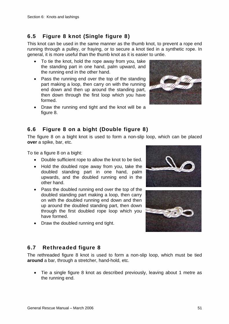
Section 6: Knots and lashings
General Rescue Manual – March 2006 51
6.5 Figure 8 knot (Single figure 8) This knot can be used in the same manner as the thumb knot, to prevent a rope end running through a pulley, or fraying, or to secure a knot tied in a synthetic rope. In general, it is more useful than the thumb knot as it is easier to untie.
• To tie the knot, hold the rope away from you, take the standing part in one hand, palm upward, and the running end in the other hand.
• Pass the running end over the top of the standing part making a loop, then carry on with the running end down and then up around the standing part, then down through the first loop which you have formed.
• Draw the running end tight and the knot will be a figure 8.
6.6 Figure 8 on a bight (Double figure 8) The figure 8 on a bight knot is used to form a non-slip loop, which can be placed over a spike, bar, etc. To tie a figure 8 on a bight:
• Double sufficient rope to allow the knot to be tied. • Hold the doubled rope away from you, take the
doubled standing part in one hand, palm upwards, and the doubled running end in the other hand.
• Pass the doubled running end over the top of the doubled standing part making a loop, then carry on with the doubled running end down and then up around the doubled standing part, then down through the first doubled rope loop which you have formed.
• Draw the doubled running end tight.
6.7 Rethreaded figure 8 The rethreaded figure 8 knot is used to form a non-slip loop, which must be tied around a bar, through a stretcher, hand-hold, etc.
• Tie a single figure 8 knot as described previously, leaving about 1 metre as the running end.

Section 6: Knots and lashings
52 General Rescue Manual – March 2006
• Take the running end and pass it around the object, then follow exactly the path back through the knot that the running end took when forming the original Figure 8.
• Dress and tighten to form the rethreaded figure 8.
6.8 Figure 8 joining knot (Figure 8 bend)
The figure 8 joining knot is the preferred knot for joining synthetic kernmantel ropes of the same diameter.
• Tie a single figure 8 knot as described previously.
• Take the running end of the second rope and follow exactly the path back through the first knot (as in the rethreaded figure 8).
• Dress and tighten both ropes to form the figure 8 joining knot.
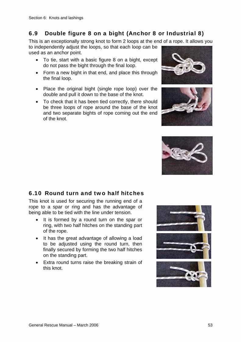
Section 6: Knots and lashings
General Rescue Manual – March 2006 53
6.9 Double figure 8 on a bight (Anchor 8 or Industrial 8) This is an exceptionally strong knot to form 2 loops at the end of a rope. It allows you to independently adjust the loops, so that each loop can be used as an anchor point.
• To tie, start with a basic figure 8 on a bight, except do not pass the bight through the final loop.
• Form a new bight in that end, and place this through the final loop.
• Place the original bight (single rope loop) over the double and pull it down to the base of the knot.
• To check that it has been tied correctly, there should be three loops of rope around the base of the knot and two separate bights of rope coming out the end of the knot.
6.10 Round turn and two half hitches This knot is used for securing the running end of a rope to a spar or ring and has the advantage of being able to be tied with the line under tension.
• It is formed by a round turn on the spar or ring, with two half hitches on the standing part of the rope.
• It has the great advantage of allowing a load to be adjusted using the round turn, then finally secured by forming the two half hitches on the standing part.
• Extra round turns raise the breaking strain of this knot.
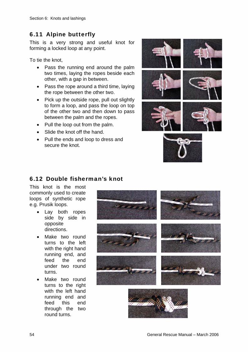
Section 6: Knots and lashings
54 General Rescue Manual – March 2006
6.11 Alpine butterfly This is a very strong and useful knot for forming a locked loop at any point. To tie the knot,
• Pass the running end around the palm two times, laying the ropes beside each other, with a gap in between.
• Pass the rope around a third time, laying the rope between the other two.
• Pick up the outside rope, pull out slightly to form a loop, and pass the loop on top of the other two and then down to pass between the palm and the ropes.
• Pull the loop out from the palm. • Slide the knot off the hand. • Pull the ends and loop to dress and
secure the knot.
6.12 Double fisherman’s knot This knot is the most commonly used to create loops of synthetic rope e.g. Prusik loops.
• Lay both ropes side by side in opposite directions.
• Make two round turns to the left with the right hand running end, and feed the end under two round turns.
• Make two round turns to the right with the left hand running end and feed this end through the two round turns.

Section 6: Knots and lashings
General Rescue Manual – March 2006 55
• Dress and pull tight. • Whilst the Double Fisherman’s knot can be very difficult to untie once it has
been loaded, its great strength is a positive advantage in rescue operations. • Take care when joining ropes of same colour that there is a knot in each
running end - otherwise they will be able to pull through.
6.13 Prusik knot The Prusik knot is a method in which a cord sling can be attached to a rope to provide an attachment loop or hand loop. The position of the loop can be easily adjusted on the main rope. The cord sling must be at least 3mm smaller in diameter than the main rope for the knot to work, and the Prusik knot must never be shock loaded. If you intend to attach a Karabiner to the Prusik loop, the double fisherman’s knot should be offset to one side. To tie the Prusik knot,
• Form the loop by joining the ends of the cord with a Double Fisherman’s Knot (as shown previously).
• Place the looped cord over the rope and pass one loop (the first loop) inside the other part of the loop (the second loop).
• Pass the first loop through the second loop two more times (so that there are three passes of the cord on each side).
• Pull the first loop evenly to ‘lock’ the turns around the rope. • It is now ready to use, in conjunction with a Karabiner or similar device. • To move the knot along the rope, remove the pressure and slide the knot
along by pushing at the turns around the rope.
6.14 Clove hitch The clove hitch is a useful knot to tie off the running end of a rope relatively quickly on equipment etc, but should not be used for rescue systems which rely on the knot holding a human load.

Section 6: Knots and lashings
56 General Rescue Manual – March 2006
To tie the clove hitch:
• Wrap the running end of a rope around a pole, or other surface. • Come around and cross the line back over itself • Take it around again and place the running end through the loop formed by
the cross.
6.15 Friction hitch This hitch (also known as the Italian hitch or Munter hitch) is used to create friction in a lowering or raising line.
• Pass a bight through a Karabiner or over hard belay point • Thread one end of the line through the bight • Pull tight to dress the hitch, and create the friction point.
6.16 Joining ropes In the rescue environment synthetic rescue lines of the same diameter can be joined using a Figure 8 Joining knot (see 6.8). Ropes of uneven diameter should be joined using a hard link, eg Karabiner connecting into a figure 8 on a bight tied in the end of each rope.

Section 8: Managing casualties
General Rescue Manual – March 2006 57
7 Ladders
7.1 Objectives By the end of studying and undertaking training on this chapter of the General Rescue Manual individuals should be able to, with other similarly trained people:
• Check a ladder • Erect a ladder (three rescuer) • Secure the ladder, both top and bottom • Climb the ladder • Lower the ladder
7.2 Introduction Ladders are readily available at most rescue sites and during a disaster may be used for improvised rescue techniques. It must be remembered however, that ladders have been constructed to be used in a specified load bearing position and should normally be used in accordance with AN/NZS Standards and the Manufacturers specifications. Some guidelines for the use of ladders are contained in the OSH Publication - Guidelines for the Prevention of Falls.
7.3 Construction Ladders come in a variety of styles, lengths and materials. Aluminium, timber and fibreglass are the three most commonly in use.

Section 8: Managing casualties
58 General Rescue Manual – March 2006
7.4 Terminology The following terminology is standard for ladder operations: Head The top of a ladder.
Stiles/Strings
The main structural part of a ladder.
Latching device/Pawl Metal hooks fitted to extension ladders to lock the
ladders in extended form.
Rungs/Rounds
Cross members used in climbing a ladder.
Hauling rope
Pulling line for raising extension ladders.
Foot/Heal The bottom or ground end of a ladder.
Single ladder A one-piece ladder.
Extension ladder
A ladder built in sections, one or more of which can be extended.
Head
Stiles (Strings)
Pulley
Guide
Latching Device (Pawl)
Hauling Rope
Rung (Round)
Foot (Heal)

Section 8: Managing casualties
General Rescue Manual – March 2006 59
7.5 Extension ladders Extension ladders are commonly in two sections, with the upper section sliding on and between the stiles of the lower section. Latching devices are fitted to the lower end of the upper section and operate on a movable shaft. Hauling ropes are taken through a sheave fixed near the top of the lower section, brought down and fastened to hooks or cleats at the bottom of the upper section. One cleat is attached to the latching device thus providing an endless line by means of which the top section can be extended or lowered and the latching devices, which are mounted on the upper section, can be engaged or released. To easily distinguish them in the dark, the stiles of the top section can have a white line to indicate the limit of safety when extended for use. Timber ladders are strengthened on the underside of the stiles by galvanised wire or fibreglass which is stretched tautly in the groove along the edge of the strings being secured top and bottom. Timber ladders are further strengthened by cross ties from stile to stile at intervals. Ladders should not be painted as paint could hide defects. A small section, at each end, may be painted for identification purposes. Timber ladders may be treated with linseed oil. Defective ladders must be withdrawn from service and labelled: “Dangerous - Do not use” and either repaired or destroyed as soon as possible.
WARNING NOTE: A hazard exists when using ladders in the vicinity of electrical wires as all ladders have the potential to conduct electricity from wires or ‘live’ roofs or structures. Rescuers must ensure overhead clearance when erecting a
ladder.
7.6 Step ladders Stepladders in common use are usually constructed of aluminium or wood, while others are of an aluminium/fibreglass composite construction. Some stepladders have flat steps on one side, and the other leg of the stepladder may be extended using round rungs to give a three to four metre single ladder. When using stepladders both as a step, or as a single ladder, care must be taken to ensure that all locks on the ladder are in place.

Section 8: Managing casualties
60 General Rescue Manual – March 2006
7.7 Inspection of ladders Every ladder should be visually inspected before each use. The main points for this inspection are:
• That there are no cracks in any part of the ladder • No evidence of rungs being loose (can be tested for twisting) where they are
attached to the strings • All bolts are secure • Rungs should be checked for wear, particularly where the pawl crosses the
rounds • The rubber feet should be checked to see that there is no deterioration • The hauling rope and pulley should be checked for defects that would affect
use.
WARNING NOTE: Aluminum ladders conduct electricity, and are liable to excessive twisting.
7.8 Maintenance of ladders Extension ladders must be regularly and carefully checked for damage or defects, in accordance with the relevant Standards. Particular attention must be paid to those ladders that are stored on vehicle roof racks and thereby exposed to the weather regularly. The ladder should be visually inspected for cracks in the timber, the security of the rungs and reinforcing wires, and for general appearance. Pulleys, latching devices and extension guides should be checked for lubrication and security, and the latching device pivot points and pulleys lubricated as necessary. Hauling ropes should be checked and replaced as necessary. Ladders should never be painted as the paint can cover quite serious cracks and defects. Better that timber ladders be left in a natural condition, and regularly oiled with linseed oil, which will keep the ladder flexible, and prevent water damage or rot. 7.9 Single rescuer ladder raise A single rescuer can quite easily and safely raise a short ladder, by placing the ladder foot against the base of the wall or some other stationary object, and under-running the ladder by walking in and pushing forward and upwards on alternate rungs.

Section 8: Managing casualties
General Rescue Manual – March 2006 61
7.10 Erecting and extending the ladder (2 rescuer) Place the foot of the ladder against a wall, kerb or some other fixed object. The ladder is under-run in the usual manner by two rescuers, extended to the required height and the foot of the ladder drawn outwards to the correct distance from the wall. 7.11 Erecting and extending the ladder (3 rescuer)
• Ideally three rescuers are required to form a ladder team.
• One person is responsible for the foot of the ladder, both in carrying and positioning where necessary.
• The others support the uppermost stile of the ladder on their shoulders.
• On arrival at the site, one person places the foot of the ladder with the reinforcing wires uppermost as near as possible to its required position and anchors it by ‘footing’. The others, working on their respective sides, raise the ladder from the underneath side to the vertical position assisted by the first person.
• The others face the ladder, each ‘footing’ it, and then the first person, pulling on the hauling ropes, extends the ladder to the required height ensuring that the latching device is properly engaged on the rung.
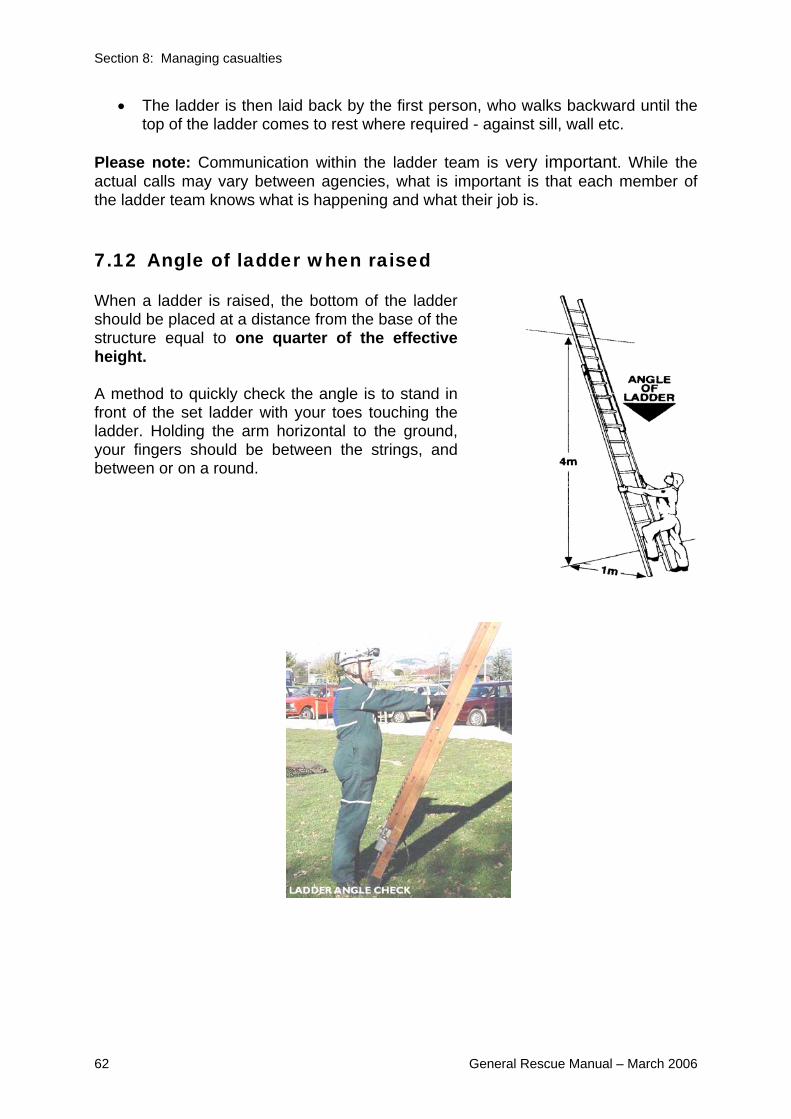
Section 8: Managing casualties
62 General Rescue Manual – March 2006
• The ladder is then laid back by the first person, who walks backward until the top of the ladder comes to rest where required - against sill, wall etc.
Please note: Communication within the ladder team is very important. While the actual calls may vary between agencies, what is important is that each member of the ladder team knows what is happening and what their job is. 7.12 Angle of ladder when raised When a ladder is raised, the bottom of the ladder should be placed at a distance from the base of the structure equal to one quarter of the effective height. A method to quickly check the angle is to stand in front of the set ladder with your toes touching the ladder. Holding the arm horizontal to the ground, your fingers should be between the strings, and between or on a round.

Section 8: Managing casualties
General Rescue Manual – March 2006 63
7.13 Overlaps Normal two part extension ladders must be extended with sufficient overlap for safety.
• For small ladders (up to 3 metres not extended) an overlap of at least three (3) rungs is recommended.
• A five (5) rung overlap is recommended for large ladders. • Wherever possible, ladders should be erected so that the head of the ladder
projects or overlaps the window, roof or other landing point by at least one metre (4-5 rungs).
7.14 Securing ladders Ladders need to be secured whenever they are positioned for ongoing access and exit from buildings. They need to be secured in such a way as to minimise risk of slippage of the head and/or foot when rescuers are using them. The decision on whether to secure the head and/or foot of the ladder needs to be made at each site the ladder is used. If the foot of the ladder is not secured, it should be “footed” whenever someone is climbing the ladder.
7.15 Securing the head of the ladder
When it is necessary to secure the head of a ladder, a lashing may be applied to any secure point, for example, a length of timber long enough to spread across the inside width of a window, may be lashed to the head of the ladder. 7.16 Securing the foot of the ladder
This may be done as shown by means of fastening to a picket or by tying back to any secure object behind the ladder eg: railings, fence posts etc.

Section 8: Managing casualties
64 General Rescue Manual – March 2006
7.17 Halving ladders In some cases it may be necessary to have two short ladders when only one long extension is available.
• This can be achieved by halving the extension ladder, (by removing the sliding extension from the main ladder).
• The ladder should be first placed on the ground, the sliding section uppermost. • The ropes are uncoupled from the pulley and hooks or cleats, the latching
device freed and the upper extension withdrawn. To reassemble, reverse the procedure.
• It should be noted that some extension ladders cannot be halved. 7.18 Ladder climbing
WARNING NOTE: Ladders must be secured or stabilised by ‘footing’ at all times whilst
rescuers are climbing.
The ladder should be climbed steadily, keeping the body erect, the head upright, arms straight but not tense, without any tendency to hug the ladder, and hands grasping the rungs at a level between the wrist and shoulders.
• It must be remembered that the legs and not the hands carry the weight of the body when climbing.
• It is generally agreed that it is safer to use the instep rather than the ball of the foot on the rungs.
• If possible, maintain 3 points of body contact to the ladder. For those more confident or experienced climbing ladders 2 points of contact is acceptable.
• When climbing off the ladder at the top the rescuer should climb one rung above the roof (or other place ladder is resting on) and then step down onto the roof testing its stability.
• In the unusual circumstance that a rescuer needs to carry out work at height from a ladder, the rescuer should be secured by independent belay/safety line, and harness.

Section 8: Managing casualties
General Rescue Manual – March 2006 65
7.19 Rules of 3 Some of the key features of working with ladders can be summarised as the: 3 rules of 3
1. 3 people to raise/lower ladder 2. 3 rungs over/above entry/access point 3. 3 points of contact when climbing up and down
7.20 Helping a casualty down a ladder Great care should be taken when helping a person down a ladder, even if that person is conscious and uninjured. Rescuers should keep in mind that many people are unaccustomed to height and may ‘freeze-up’ or lose their hold.
• The rescuer should take a position, one rung below the casualty, with arms encircling the casualty’s body and grasping the rungs.
• The rescuer should keep in step with the casualty, letting them set the pace. The rescuer’s knees should be close together, to ensure support in case the casualty loses hold or becomes unconscious.
• The rescuer should also talk to the casualty to keep up morale and overcome fear.
• If the casualty becomes unconscious, they should be permitted to slip down until the crutch rests on the rescuer’s knee.
• By repeating this procedure for each step down the ladder, the rescuer can lower the casualty to the ground.
For both methods, as a minimum, a safety line should be attached to the victim, but ideally a suitable harness, which can be belayed via the top round of the ladder. In many cases a safety line/harness may also be attached to the rescuer. Note: The diagrams show two methods. The rescuer will need to select the appropriate method for the situation.
WARNING NOTE: This technique could exceed the safe working load of the ladder or de-
stabilise the ladder.

Section 8: Managing casualties
66 General Rescue Manual – March 2006
8 Managing casualties
8.1 Objectives On completion of study and/or instruction on this chapter of the General Rescue Manual individuals should be able to:
• Describe the START triage system • Describe 4 items that should be included on a casualty label
8.2 Introduction Using General Rescue techniques contributes to the overall goal of “rescuing the maximum number of people in the minimum amount of time”. To achieve this rescuers need methods of prioritising casualties for ongoing treatment and rescue. The initial assessment and prioritisation will be done in the reconnaissance phase, but will be ongoing, as conditions, both of the casualties and the environment, will often change throughout the rescue process. In this section we describe one method that has been developed to sort, or “triage”, a large number of casualties in a short period of time and with little medical knowledge. The method explained below is known as START. Please note that other groups/emergency services may use other, often more complex, methods of triaging based on their advanced medical skills and knowledge. Co-ordination and liaison between groups will be needed, if multiple agencies are working on a site.
8.3 START START was developed in California in the early 1980’s by Hoag Hospital and Newport Beach Fire Department. S Simple
T Triage
A And
R Rapid
T Treatment
Those with minor injuries are immediately tagged GREEN - often referred to as “walking wounded”. START allocates all other casualties a triage category based on assessment.

Section 8: Managing casualties
General Rescue Manual – March 2006 67
• Red: Immediate - Life-threatening but treatable injuries requiring rapid medical attention.
• Yellow: Serious -Not immediately life threatening. • Black: Recognised futility - Dead or still with life signs but injuries are
incompatible with survival in existing conditions. The triage category is determined by quickly assessing (approx 30 seconds) the casualty’s RPM:
R - Respiration P - Perfusion- sufficiency of blood flow M - Mental State
The following flow chart outlines the process of determining the category for each casualty.
8.4 Labelling Whatever triage system is used, it is important that all casualties located during a rescue operation are labeled with a casualty tag. There is no nationally recognised casualty tag and many regions have developed their own casualty tags. Whatever tag is used the basic information that should be included is:
• Identifier for each casualty - their name and/or an assigned number. • The location they were found • The identification of the person who found them
Simple Triage And Rapid Treatment
RED
Section 8: Managing casualties
68 General Rescue Manual – March 2006
• The triage outcome undertaken at the time (colour assigned) • Any treatment given
8.5 Consumer Code of Rights- Health and Disability Commission
The Code of Health and Disability Services Consumers' Rights became law on 1 July 1996 as a regulation under the Health and Disability Commissioner Act. It is obviously intended for “everyday” service provision as opposed to during an emergency, however during rescue activities where care is being provided to a individual the Code should be considered.
The Code is very wide and extends to any person or organisation providing, or holding themselves out as providing, a health service to the public, or a section of the public, whether that service is paid for or not.
The obligation under the Code is to take "reasonable actions in the circumstances to give effect to the rights, and comply with the duties”.
There are 10 rights in the Code:
1. The right to be treated with respect
2. The right to freedom from discrimination, coercion, harassment, and
exploitation
3. The right to dignity and independence
4. The right to services of an appropriate standard
5. The right to effective communication
6. The right to be fully informed
7. The right to make an informed choice and give informed consent
8. The right to support
9. Rights in respect of teaching or research
10. The right to complain

Section 9: Stretchers
General Rescue Manual – March 2006 69
9 Stretchers
9.1 Objectives On completion of study and/or instruction on this chapter of the General Rescue Manual individuals should be able to:
• Describe the characteristics of the four main types of stretcher used, And with other similarly trained people: • Load a person into a stretcher using four rescuer, blanket and clothing lifts • blanket and lash people into the folding, board and basket stretchers
9.2 Introduction The four categories of stretchers in most common use are:
• Folding or pole stretcher - commonly referred to as NATO or Mk II stretchers • Board rescue stretchers • Basket stretcher - often referred to by brand names of Stokes Litter, or Ferno-
Washington • Wrap-around stretchers
9.3 Folding or pole stretchers
WARNING NOTE: These stretchers are not suitable for lowers, and are only appropriate for
casualty movement on the flat.
The folding stretcher must be set up as follows before a casualty can be transferred to it:
• Unfasten the straps that hold the stretcher closed.
• Spread open the stretcher and lock the spreaders in place by pushing on each bar with your foot, from the side to avoid standing on the bed, until it locks into place.
• Do not use your hands as they can be pinched by the hinges.
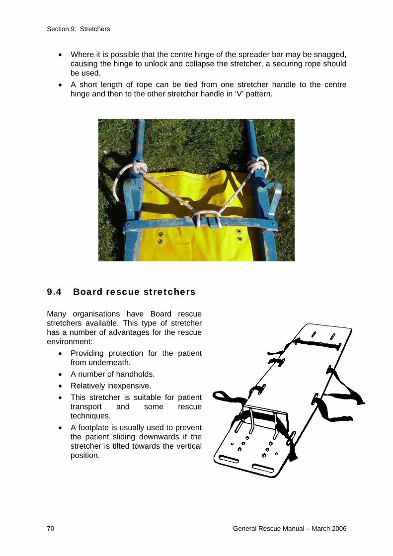
Section 9: Stretchers
70 General Rescue Manual – March 2006
• Where it is possible that the centre hinge of the spreader bar may be snagged, causing the hinge to unlock and collapse the stretcher, a securing rope should be used.
• A short length of rope can be tied from one stretcher handle to the centre hinge and then to the other stretcher handle in ‘V’ pattern.
9.4 Board rescue stretchers Many organisations have Board rescue stretchers available. This type of stretcher has a number of advantages for the rescue environment:
• Providing protection for the patient from underneath.
• A number of handholds. • Relatively inexpensive. • This stretcher is suitable for patient
transport and some rescue techniques.
• A footplate is usually used to prevent the patient sliding downwards if the stretcher is tilted towards the vertical position.

Section 9: Stretchers
General Rescue Manual – March 2006 71
WARNING NOTE: A rope lashing system should be used at all times other than when the
stretcher is moved over smooth and flat ground. Care must be taken if this stretcher is used for lowering as the high centre of gravity can cause the stretcher to invert, particularly when using the two-
point suspension method.
9.5 Basket stretchers There are two types of basket stretcher commonly in use. The older type has a strong tubular aluminium frame covered with ‘chicken wire’, whereas the newer has a formed plastic, fibreglass, or aluminium basket attached to a tubular aluminium frame. The newer designs have an advantage in that they are less likely to be snagged or penetrated than the wire model. Other than the very old wire designs, these stretchers can accommodate a ‘scoop’ style stretcher, or spinal board, thus making the transfer of a spinal casualty easier.
Basket stretchers provide good protection for casualties and are ideally suited to a range of rescue techniques. The main drawback is the relative expense in comparison to other types of stretchers.
9.6 Wrap-around stretchers Wrap-around style stretchers such as the Sked and the Fallright Evacuation Splint, whilst quite different in design and construction, share the same critical feature in that

Section 9: Stretchers
72 General Rescue Manual – March 2006
they conform very closely to the casualty’s body, thus adding very little width or bulk for confined space operations.
• Each of the wrap-around style stretchers has its own advantages and disadvantages that must be weighed up prior to use.
• Each has its own individual casualty securing system. Manufacturer’s recommendations about methods of attaching lowering and guide ropes must be followed.
9.7 Blanketing the stretcher Before a casualty is placed on a stretcher, it should be covered with a blanket. This adds to comfort, keeps the casualty warm, and to a large degree helps immobilise any fractures that may have been sustained. In very warm weather a cotton bed sheet or sheets may be used instead of blankets.
Single blanket method Lay one open blanket diagonally down the stretcher with the corner of the blanket in the centre of the top of the stretcher, and about 150mm overlapping.
• Place the casualty on the blanket with the head level with the top.
• Fold over and tuck in the lower half of the blanket.
• Do likewise with the top half.
9.8 Blanketing - Lateral/Recovery position In addition to warmth, comfort, and immobilisation, the blanket is used for padding to keep the patient in the required lateral/recovery position. The following is the recommended method: Before folding the blanket around someone :

Section 9: Stretchers
General Rescue Manual – March 2006 73
• Roll a blanket end to end and position it on the stretcher so that the roll is used to pad the patient’s back.
• A second blanket is placed on the opposite side of the stretcher to support arm and stop patient rolling onto stomach.
9.9 Loading the stretcher • Loading a stretcher is an important part of casualty handling. • Correct methods are essential for the well-being of the casualty to prevent
aggravation of injuries. • Final checks must be made by hand to ensure that a casualty is actually ready
to lift before a lift is executed.
WARNING NOTE: The casualty’s head and neck must be supported at all times.
Casualty reassurance is important in all techniques to reduce the anxiety of the casualty, and reduce the risk of them panicking which increases risk to
rescuers.
9.10 The four rescuer method When using four rescuers to load a stretcher and where spinal injuries are not suspected, the following method can be used:
• The stretcher is made ready and placed near the casualty’s head or feet.
• The leader instructs three other rescuers to kneel down on one knee on one side of the casualty (casualty lying flat on their back). They all have the knee closest to the casualty’s head elevated.
• The leader kneels near the casualty’s head to support the neck.
• The other three place their hands and arms underneath the casualty. Usually under the shoulders, small of the back, thighs, knees and calves.
• The leader gives the order: Prepare To Lift and, if no one dissents, follows it with Lift, whereupon all four lift.
• If necessary, the casualty can be briefly supported on the rescuers’ knees. The stretcher is then placed under the casualty.

Section 9: Stretchers
74 General Rescue Manual – March 2006
• Final orders are Prepare To Lower, then Lower. • The three rescuers, assisted by the leader, lower the casualty on to the
stretcher.
9.11 Blanket lift (four or six rescuers) This is an effective method for loading or moving a casualty in a restricted space.
• Make a stretcher ready using one blanket. • Roll a blanket lengthways for half of its width
and lay the rolled section along the side of the casualty (casualty flat on back).
• The leader then directs two (or three) rescuers to kneel down on each side of the casualty.
• The rescuers on one side ease the casualty over on one side and the rolled section of the blanket is pushed well underneath the casualty.
• With the rolled up section of the blanket now under the centre of the casualty, the casualty is eased over in the opposite direction and the blanket is unrolled. The casualty should now be lying flat on their back.
• The sides of the blanket are rolled up close to the casualty’s body to provide handgrips for the bearers. They cross arms to help keep the lift even and the spine aligned.
• On the order from the leader, the casualty is lifted waist high, and carried to the stretcher.
• On the order from the leader, the casualty is lowered onto the stretcher.
• The blanketing is then completed with one blanket, leaving the lifting blanket in position.
• This ‘blanket carry’ can also be used as an improvised stretcher for carries over moderate distances.
WARNING NOTE: Suspected spinal injured casualties can be safely transported by this
method with correct immobilisation of the spine and with particular attention paid to the head and neck.

Section 9: Stretchers
General Rescue Manual – March 2006 75
9.12 Clothing lift (Three rescuers) This is an emergency method which can be used when the casualty’s injuries are not severe and time is critical.
• Blanket a stretcher and place it close to the side of the casualty.
• Tie the casualty’s hands together with a triangular bandage or similar material, or place in pockets/under their belt if unconscious.
• Grab the casualty’s clothes along the centre of the body, and roll any loose fabric to form a hand grip.
• Three rescuers take up the position on the opposite side of the casualty to the stretcher and position their hands.
• The normal commands are given (Prepare To Lift, etc) and the casualty is gently lifted, then lowered onto the stretcher.
9.13 Webbing bands (Five rescuers) In some cases it may be necessary to transport a casualty some distance to a place where they can be loaded onto a stretcher. Webbing bands can greatly assist this operation. While there are many configurations that can be used, one suggestion is:
• The bands are placed in position by pushing the long steel handle under the natural body hollows and see-sawing the bands into the required position, i.e. under the buttocks and shoulders.
• After bands are correctly positioned, the five rescuers take up position, crossing bands to help keep lift level and align casualty’s spine. The normal commands are given (Prepare To Lift, etc) and the casualty is gently placed on the stretcher.
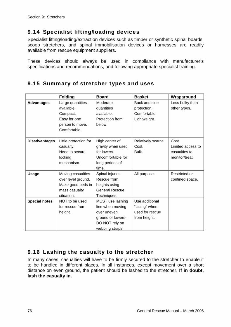
Section 9: Stretchers
76 General Rescue Manual – March 2006
9.14 Specialist lifting/loading devices Specialist lifting/loading/extraction devices such as timber or synthetic spinal boards, scoop stretchers, and spinal immobilisation devices or harnesses are readily available from rescue equipment suppliers. These devices should always be used in compliance with manufacturer’s specifications and recommendations, and following appropriate specialist training.
9.15 Summary of stretcher types and uses Folding Board Basket Wraparound Advantages Large quantities
available. Compact. Easy for one person to move. Comfortable.
Moderate quantities available. Protection from below.
Back and side protection. Comfortable. Lightweight.
Less bulky than other types.
Disadvantages Little protection for casualty. Need to secure locking mechanism.
High center of gravity when used for lowers. Uncomfortable for long periods of time.
Relatively scarce. Cost. Bulk.
Cost. Limited access to casualties to monitor/treat.
Usage Moving casualties over level ground. Make good beds in mass casualty situation.
Spinal injuries. Rescue from heights using General Rescue Techniques.
All purpose. Restricted or confined space.
Special notes NOT to be used for rescue from height.
MUST use lashing line when moving over uneven ground or lowers- DO NOT rely on webbing straps.
Use additional “lacing” when used for rescue from height.
9.16 Lashing the casualty to the stretcher In many cases, casualties will have to be firmly secured to the stretcher to enable it to be handled in different places. In all instances, except movement over a short distance on even ground, the patient should be lashed to the stretcher. If in doubt, lash the casualty in.

Section 9: Stretchers
General Rescue Manual – March 2006 77
9.17 Lashing the folding stretcher The ideal size and length for stretcher lashing is 12 metres of 11mm or 12mm rope.
• Commence the stretcher lashing by forming a Figure 8 on the Bight around one of the top stretcher handles.
• From this point take three Half Hitches around both the casualty and the stretcher, first in the region of the chest, the second in the vicinity of the wrist and the third hitch just above the knees.
• A round turn is then taken around the feet and three Half Hitches applied to those already formed on the opposite side of the casualty’s body.
• The lashing is finished with a Round Turn and Two Half Hitches on the remaining stretcher handle.
• The position of the three securing Half Hitches can be varied according to the location of the injuries that the casualty has sustained. In the case of a female casualty, the top securing hitch should be placed just above the breast line.
• Bricks or timber placed under the stretcher D’s before lashing commences, will enable the rope to be passed under the stretcher more easily.
9.18 Lashing - Lateral/Recovery position The lashing of the stretcher differs from the normal method in that the rope does not pass around the feet.
• The middle lashing is positioned under the casualty’s buttocks to prevent movement downwards.
• Instead of passing a loop around the casualty’s feet, the line is Half Hitched around each handle at the foot of the stretcher.

Section 9: Stretchers
78 General Rescue Manual – March 2006
9.19 Lashing - Board rescue stretcher The patient should be lashed to the board rescue stretcher whenever it is going to be lowered or moved over uneven ground, eg: rubble, confined spaces. Where nylon straps come with the stretcher, they can be used, but not as the primary way of securing a casualty to the board rescue stretcher. A 12m rescue line, or climbing tape, is used to lash the board rescue stretcher.
The process is as follows:
• Begin with a Rethreaded figure 8 through the top- most handhold or hole.
• Pass the line down the side of the board. • Take a complete turn under the board and back
across the casualty’s chest. • Form a hitch and tighten gently. • This is repeated across the casualty’s wrists and
again just above the casualty’s knees. • A complete round turn is taken around the feet. • The rope is then taken up the other side of the
board forming hitches on each turn of the lashing. • Complete with a round turn and 2 Half Hitches on
the handhold opposite where the lashing was started.
Some board rescue stretchers have runners underneath with slots in them for the rope to pass through. This has the advantage of minimising ropes being scraped on the ground or building edges.
9.20 Alternate Board rescue stretcher lashing An alternate method for lashing the board rescue stretcher where there is insufficient room for the rope to pass through the runners, and there is a risk of the ropes being damaged or caught is:
• Begin the same as lashing the basket stretcher (see 9.22 below) with a hitch around each of the bottom handholds.
• Criss-cross up the stretcher coming from the outside of
the stretcher, then up through the handhold and diagonally across to the other side other the casualty. Working this way minimise pressure on the handholds.
• Finish with a Round Turn and 2 ½ hitches adjacent to
the casualty’s shoulders.

Section 9: Stretchers
General Rescue Manual – March 2006 79
When this lashing is used and the stretcher is going to be lowered consideration should also be given to the Improvised Casualty Harness shown in 9.23. Note: This technique is shown without a blanket for clarity- a blanket would normally be used.
9.21 Securing a basket stretcher with securing straps Some basket stretchers are supplied with securing straps with seatbelt buckles or ‘Fastex’ clips. These should be used in conjunction with a lashing, whenever the basket stretcher is used for anything other than moving the stretcher over even ground.
• When the patient is small there will be gaps between the patient and the sides of the stretcher. It is not improbable that a casualty could slide out from under the straps if the stretcher was tilted. Gaps between the casualty and the stretcher sides may be filled with blankets, clothing or pillows etc. before the straps are snapped in place.
• Remember that the purpose of strapping or lashing is to combine the patient and the stretcher in a solid manageable unit capable of being carried over hazardous terrain, or for rescue.
9.22 Securing a basket stretcher by lashing • The casualty can be lashed securely to a basket stretcher with a 12m length of
11mm rope, or tape, with the lashing pattern dictated by the casualty’s injuries and size and by the attitude through which the stretcher will move.
• If the basket stretcher has no foot plate, the casualty’s feet should be secured to prevent them from sliding down the stretcher.
• If the casualty is to be shifted in a vertical position the head of the patient must be secured. Pack soft material on either side of the casualty’s head and tie a length of bandage to one lower rail, lay it over the casualties head (not covering the eyes) and tie the other end to the opposite lower rail.
• It is important to continually reassure any casualty who is secured to a stretcher in such a confining manner.
One option for the securing the casualty is shown below:
• Find the middle of the tape or 12m line • Hitch through hand-hold at feet end • Criss-cross up stretcher • Finish with round turn and 2 ½ hitches around
handholds adjacent to the patient’s shoulders

Section 9: Stretchers
80 General Rescue Manual – March 2006
9.23 Improvised casualty harness An improvised casualty harness can be fitted to either the basket stretcher or board rescue stretcher. It is useful whenever the footplate is not used/secured e.g. small people, lower leg injuries, alternate board rescue stretcher lashing (9.20) This harness can be made using rope or tape.
• Form a loop in the middle of the rope
• Bring this between the casualty’s legs
• Bring the tails around the buttocks and pass through the loop
• Ties off to hand holds on the side of the stretcher
using Round Turn and 2 ½ hitches.
Note: This technique is shown without a blanket for clarity- a blanket would normally be used.
9.24 Moving a stretcher over uneven ground The technique for moving over rubble is covered in the USAR Awareness Student Manual, and the principles remain the same for any uneven ground. A stretcher should, wherever possible, be carried in the horizontal position or slightly ‘head high’. When moving over debris or uneven ground, this may prove to be difficult, but risks to both casualty and rescuers can be reduced to a minimum by adopting the following procedures:

Section 9: Stretchers
General Rescue Manual – March 2006 81
Using six rescuers Moving a heavy casualty over difficult debris conditions for any more than 10 or 15 metres, will almost certainly require 6 rescuers.
• The leader should position three on each side of the stretcher.
• On the order Prepare To Lift, the rescuers stoop and grasp the stretcher. When all is in readiness, the leader gives the order Lift and the stretcher is raised to waist height.
• The next order will be Prepare To Pass. Any member of the team who for any reason is not ready should inform the leader.
• Good footing on debris is hard to find, and care should be taken in this regard.
• On the command Pass, the stretcher is passed until such time as it is supported by four rescuers, leaving two spare.
• These two then climb carefully around the stretcher and take up positions at the other end of the stretcher.
• The process is then repeated until the stretcher arrives on clear, solid ground.
• It is stressed that this operation calls for a high degree of teamwork and that the leader must retain control throughout.
• The leader must ensure that while the stretcher is being passed, no member of the team is moving on the debris.
9.25 Moving a stretcher in restricted spaces In small spaces, if there is sufficient height and the casualty has been lashed to the stretcher, it may be stood on end and moved around sharp corners.
• Where the height is insufficient to permit this method being used, a compromise between the vertical and horizontal positions is necessary.
• The casualty should be carried feet first as far as the middle of the right-angle bend, then the foot of the stretcher is placed on the ground and the head end lifted as high as the situation will permit.

Section 9: Stretchers
82 General Rescue Manual – March 2006
• The stretcher can be worked around the bend, one rescuer easing the foot end and the other the head.
• Under these conditions the stretcher should not be tipped on its side. To do so would only increase its height and also the difficulty in handling it.
• ‘Wrap-around’ style stretchers are specifically designed for confined spaces and that these should be used wherever possible.
9.26 Improvised stretchers In any disaster, there may be insufficient stretchers immediately to hand for the number of casualties involved. Such situations will normally be multi-agency responses and the resources of all involved agencies should be utilised. There are many methods of improvisation and some imagination should be used when confronted with the problem. A number of the more commonly used methods are described here.
WARNING NOTE: Improvised stretchers should never be used for rescue techniques, other
than moving over flat ground.
Platform stretchers Improvised platform stretchers can readily be devised from doors, sheets of galvanised iron, or bed frames.
Pole stretchers These stretchers are very simple to make and require two poles about two metres long. Stout broom handles, water pipe or 50mm x 50mm timber are quite appropriate for this job.

Section 9: Stretchers
General Rescue Manual – March 2006 83
The poles should be laid parallel on the ground and about 600mm apart. The bed of the stretcher can be formed from a blanket, sacks, overalls or coats. The weight of the casualty will hold the blankets in place.
Ladders Where for any reason, a very narrow stretcher is required, such as for passing through small window openings, tunnels etc. a small ladder or one half of a small extension ladder can be used to an advantage. A decking of boards should be placed on the ladder (if available) and it is then blanketed in the normal way.
The lashing line is attached to a ladder string using a rethreaded Figure of eight, and then the lashing done at same positions as board rescue stretcher.
Chairs A strong style kitchen chair can be used for carries of casualties without serious injuries.

Section 11: Non-stretcher based rescue techniques
84 General Rescue Manual – March 2006
10 Stretcher based rescue techniques
10.1 Objectives By the end of studying and undertaking training on this chapter of the General Rescue manual individuals should be able to, with other similarly trained people:
• select appropriate and perform safely a variety of low and steep angle rescue techniques including a stretcher lower/raise in a low angle situation
• Single, Two Point and Four Point Lower in the limited high angle environment. • Ladder Slide • Ladder Hinge
10.2 Introduction In any disaster occurring in an urban environment, it is likely that large numbers of casualties could be trapped in upper floors of buildings, in basements or other depths, or in many other difficult or inaccessible areas. In each case, the method of rescue will be dictated by the circumstances. This section attempts to provide some of the alternative methods of rescue for the low and steep angle situation. The simple option of carrying a casualty up or down an inside stairway must not be overlooked.
10.3 Definitions Low angle rescue Low angle rescue techniques are used to undertake rescues on slopes of less than 30 degrees, e.g. gentle slope or rubble pile. They are used when the person’s injuries require them to be in a stretcher. The main weight of the patient is taken by the rescuers positioned on the side of the stretcher, but allows control in the event that the rescuers may slip or trip. Steep angle rescue Steep angle rescue techniques are used when the situation requires the lowering, or raising, of the stretcher in an angle generally between 30 and 60 degrees. In this situation the weight of the patient and stretcher is taken by the lowering lines. Because of their specialist nature, steep angle rescue techniques are not covered in this manual. Anyone interested should consult the USAR Best Practice Guideline: Rope Rescue Tier Model. High angle rescue High angle rescue is used for rescues above 6 metres and or where the angle of the incline exceeds 60 degrees. It requires specialist equipment and highly trained rescuer. Because of their specialist nature, high angle rescue techniques are not covered in this manual. Anyone interested should consult the USAR Best Practice Guideline: Rope Rescue Tier Model.

Section 11: Non-stretcher based rescue techniques
General Rescue Manual – March 2006 85
Limited high angle rescue This refers to rescue techniques that can be used for the high angle environment, where the section of high angle (over 60 degrees) does not exceed 6 metres. This can include natural terrain or buildings, provided it does not exceed 6 metres.
10.4 Additional equipment Some of these techniques will be made easier by the use of additional equipment, now often carried by General Rescue Team, for example Karabiners, descenders, and climbing tape. Teams are encouraged to train for all circumstances.
10.5 Low angle rescue techniques HAZARD ID AND CONTROL
HAZARD CONTROL MECHANISM
Slipping/unstable rubble
Rescuers to wear all standard PPE Use scouts to select and mark most stable and safe route for stretcher
Surface hazards Use Basket Stretcher in preference due to side protection offered
Injury to rescuers Use of ergonomic lifting and handling techniques
Rope breaking Use standard 11mm static lines
Low angle rescue techniques have two main components: the attachment of a line to the stretcher, and the creation of friction to allow the stretcher to be “caught” in the case it is dropped, or builds up too much speed.
10.6 Attachment of the line A line should be attached to the head of the stretcher, encompassing the aluminium frame in a basket stretcher, or spreading the weight on a board stretcher. There are two main options. Option one: This option is very easy and very strong but does require the use of an additional line. It is created by tying a figure 8 on the bight in the centre of a 12m line. It is then ½ hitched around the top handles and then thread down the sides taking a turn around each handle location. It is finished with a round turn and 2 ½ hitches. A second line is then attached to the figure 8 using a Karabiner or rethreaded figure 8 knot.
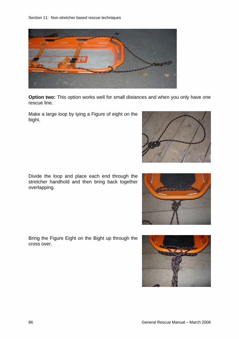
Section 11: Non-stretcher based rescue techniques
86 General Rescue Manual – March 2006
Option two: This option works well for small distances and when you only have one rescue line. Make a large loop by tying a Figure of eight on the bight. Divide the loop and place each end through the stretcher handhold and then bring back together overlapping. Bring the Figure Eight on the Bight up through the cross over.

Section 11: Non-stretcher based rescue techniques
General Rescue Manual – March 2006 87
10.7 Creation of the friction/“catch” The type of friction or catch used in the low angle situation will depend on factors such as the risk, equipment available, personnel available and height of the slope. Body belay The body belay is the most simple and involves using a rescuer sitting down on stable ground and placing the belay line around their lower back. This method should never be used if there is any risk of a rescuer/rescuers being required to hold the whole weight of the stretcher. Simple friction This method involves wrapping the belay line around a solid object such as a pipe or “I” beam creating a round turn. The number of round turns can be increased if more friction is required. This method does not create a “catch” and will only work if the attendant is able to maintain the friction. Therefore it should only be used where the friction is used to assist holding the load as rescuers re-position themselves and would normally not be expected to take the whole stretcher load. Tandem Prusiks A tandem Pusik system can be used independently or in combination with simple friction (although this will require two people looking after the system) Tandem Prusiks are attached to a solid object using a sling/s and Karabiner. When applied to the belay line, they are kept loose until such time as there is a “jerk” on the system and they “catch” the load.
10.8 Limited High angle rescue techniques Single, two and four point lowers These lowers are named by the number of points of suspension on the stretcher. The choice of lowering technique will depend on the structural limitations, casualty’s injuries and equipment available. In the majority of cases wherever possible, it is recommended that casualties be recovered in a horizontal position. HAZARD ID AND CONTROL HAZARD CONTROL MECHANISM Rope failure/not long enough Only 11mm static Kernmantle lines used
(see Chapter 4) Line lengths checked before each lower, after passed around hard belay point
Rescuer falling from height All rescuers to be tied off if within 2m of edge, or to be behind fence or solid barrier no less than 900mm high
Losing rope control Use hard belays whenever possible Stretcher breakage Use only Board Rescue or Basket

Section 11: Non-stretcher based rescue techniques
88 General Rescue Manual – March 2006
stretcher Loss of control of lower Use of series of standard commands for
lower control Failure of straps on basket stretcher Additional lashing line or tape used General scene control/safety For the Single and Four Point Lower
there should be a rescuer at the bottom to receive the stretcher
10.9 Guide lines Guide lines may be attached to stretchers during lowering operations to prevent the stretcher from spinning and in order to clear obstacles. These guide lines are attached to the head and/or the foot of the stretcher, normally using a re-threaded Figure 8. Rescuers controlling guidelines should wear gloves.
10.10 Single point lower The single point lower can be used to maintain the stretcher in the horizontal position and works well when you have a high anchor point to run the main lowering line through. A pulley or karabiner is desirable for this. A mechanical descender can be used to control the rate of descent. If this is not available friction needs to be created by the use of round turns or a Friction Hitch. A safety line should be attached to the head of the stretcher as per 10.6. A 12m line is used to create the bridle on the stretcher and then the main line is attached to the lifting point using a Rethreaded Figure 8.
To create the bridle: Put a figure 8 on the Bight in the center of a 12m line Place that on approximately the casualty’s chest Form a hitch around the top handhold on each side of the stretcher
Pass the line along the side of the stretcher and form another hitch on each side at one of the bottom handholds Bring the running ends up to the centre and connect to the first figure of 8 on the bight by either:

Section 11: Non-stretcher based rescue techniques
General Rescue Manual – March 2006 89
Tying a figure 8 on the bight in each of the running ends and attaching the main lowering lines by means of a Rethreaded figure of 8, or:
Using a Karabiner - in this case you can attach the running ends with a round turn and 2 ½ hitches which is more easily adjusted to balance the stretcher.
10.11 Two point lower This method is used for raising or lowering a stretcher over relatively short distances and where the casualty’s injuries allow for transport vertically. The casualty is blanketed and lashed to a stretcher in the normal way, with the possible addition of a bandage tied across the forehead to prevent the head flopping forward should the casualty become unconscious.
• Two lowering ropes are tied to the head of the stretcher, one on each side, by means of a rethreaded figure 8, on the one but top handhold, and a ½ hitch around the top handhold.
• The same procedure is used for the foot of the stretcher and the bottom lines are passed out to the two rescuers on the ground.
• The Team Leader (or leader of the “top team”) checks if all rescuers are ready, by calling “top team

Section 11: Non-stretcher based rescue techniques
90 General Rescue Manual – March 2006
ready?” and waiting for a reply. This is followed by “bottom team ready?”. If all rescuers are, the rescuers who are lowering the stretcher are directed to “tension” their lines.
• The leader of the top team, and or any rescuers at the top who are free to assist, ease the stretcher over the edge of the wall with the tension maintained on the lowering lines.
• The two rescuers on the ground guide the stretcher clear of any obstruction and walk in, while still pulling on the guide lines, to support the stretcher on either side as it comes down.
• This technique can be used equally well inside a building, using a hole found or cut in the floor.
• The minimum team size for this lower is six, but as the weight is taken by two points a hard belays should be used rather than a waist belay whenever possible.
10.12 Four point lower • Where it is essential to keep the casualty horizontal, the four-point lower can
be used. With four points of suspension it also is more desirable for very heavy patients, particularly if hard belays are not available.
• The stretcher is rigged and lowering lines are attached in exactly the same way as for the two-point suspension, except that the guide lines may not be required if the drop to the ground is clear of obstacles.
• The casualty is then, or sometimes may already be, placed in the stretcher, blanketed and lashed appropriate to their injuries.
• Once all rescuers are ready, and lines are tensioned if the hole allows, place the stretcher diagonally across the hole.
• As instructed the stretcher is then “straightened up” and lowered evenly. • If the hole does not allow this the rescuers on the far side pull the stretcher
across until it is located over the centre of the hole.

Section 11: Non-stretcher based rescue techniques
General Rescue Manual – March 2006 91
• Four rescuers are required to lower and at least one at the bottom to receive. NOTE: An alternate method of performing the four point off a ledge involves the
addition of two lines on the inside edge of the stretcher which are passed underneath the stretcher to two rescuers on the ground who pull the stretcher clear of the wall.
10.13 Ladder Slide The Ladder Slide is very similar to a 2 Point Lower, with a ladder used to take some of the weight of the stretcher. The Ladder Slide is the most practical option for raising a loaded stretcher, e.g. out of a basement. It can also be used for lowering and is an option if no hard belay points are available. The process below describes use of the Ladder Slide for raising a stretcher - for lowering, reverse the process (excluding the first two steps).
• The casualty is blanketed and lashed to a stretcher, and two lines are secured to the head end using ½ hitch and rethreaded figure 8.
• The ladder is placed in position by three rescuers, and moved until it forms an angle of approximately 45 degrees.
• One rescuer foots the ladder and/or secures the bottom to pickets, and one or two rescuers act as human props.
• The lines are passed to rescuers at the top of the ladder and passed around belay points if available.
• The stretcher is placed on the ladder.

Section 11: Non-stretcher based rescue techniques
92 General Rescue Manual – March 2006
• The stretcher is then pushed up the ladder by a rescuer who climbs up the ladder, until such time as the head end passes clear of the opening.
• Rescuers at the top who are not holding the raising lines can then pull the stretcher in and move away from the edge/window.
WARNING NOTE: In the ladder slide technique, the ladder is used in a manner other than that for
which it was designed and manufactured. This is an improvised technique. As the load on the centre of the span will be close to 150kg, the span must be
propped by one or two rescuers, or shored.
Some specific points to be observed with the Ladder Slide are:
• Communication between the rescuer coming up the ladder and the top team is very important.
• There should only ever be one person, either casualty or rescuer, on each section of the ladder at any time.
• Where a timber ladder is used, it must be reinforced with wire or fibreglass stile supports.
• Where a basket stretcher is used on an alloy ladder, there will be very little friction.
• Where ladders are extended to provide sufficient reach, the overlap should be lashed with short rope or cord to avoid stretcher catching on the pulley and dragging the extension with it.

Section 11: Non-stretcher based rescue techniques
General Rescue Manual – March 2006 93
10.14 Ladder Hinge This is a relatively simple method of rescuing a casualty from an upper floor, when it is desirable to keep the stretcher horizontal, or the upper building is so unstable that it cannot be used to assist in the operation. It should be noted that the ladder is used with its reinforced side away from the structure.
• The casualty is blanketed and lashed to a stretcher in the normal way. • The ladder is placed vertically against the wall in front of the opening. • A rethreaded figure 8 is tied to one of the
handholds at the foot of the stretcher in the same manner as for a Two Point Lower.
• The rope is then taken around the stile of the ladder in a Half Hitch and the stretcher is raised until it is about 250mm clear of the window sill.
• Six to eight round turns are taken around the ladder rung, the rope is Half-Hitched to the stile on the opposite side of the ladder, and finally secured to the other side of the stretcher using a Round Turn and two Half-Hitches.
• Alternately, webbing and Karabiners can be used. • Lowering lines are attached to the head end of the stretcher, and when all
is secure, the word is passed to the leader who gives the orders: Prepare To Lower and then: Lower.
• The stretcher is passed out of the window by hand until the head end can be supported by the lowering lines.
• One rescuer remains close to where the ladder has been footed, ensuring no side-sway develops.
• 1-2 rescuers then walk backwards, hand-over-hand with each rung, controlling the speed of the whole operation.
• The stretcher should finally come to rest on top of the ladder flat on the ground, from where it can be quickly disconnected and the casualty removed to safety.
• For larger ladders additional lines can be attached to the head of the ladder and used as guidelines, controlled by people on the ground.
NOTE: this method can also be readily used to raise a casualty.
WARNING NOTE: In the ladder hinge technique, the ladder is used in a manner other than that for
which it was designed and manufactured. The ladder must have a reinforcing wire.

Section 11: Non-stretcher based rescue techniques
94 General Rescue Manual – March 2006
11 Non-stretcher based rescue techniques
11.1 Objectives On completion of training on the techniques described in this chapter individual should be able to:
• Tie and fit to another person the Vertical Lift Knot • With other similarly trained people, use this knot to safely lower someone
from height not exceeding 2 stories
11.2 Introduction This chapter describes a technique, the Vertical Lift Knot (VLK), that can be used to rescue casualties without the use of a stretcher. It can also be very useful for rescuer entry into and/or exit from sites. The advantages of the VLK is that it requires minimal equipment and is relatively quick to set up. Often the same anchors can be re-used, meaning a large number of people can be rescued quickly. The main disadvantage is that it provides little or no protection for the person being rescued. It may also worsen injuries, so it’s use is generally limited to the “walking wounded”. HAZARD ID AND CONTROL
HAZARD CONTROL MECHANISM Rope failure/not long enough Only 11mm static Kernmantle lines used
(see chapter 4) Line lengths checked before each lower, after passed around hard belay point. A safety line is used- a re-threaded figure 8 around the chest.
Rescuer falling from height All rescuers to be tied off if within 2m of edge, or to be behind fence or solid barrier no less than 900mm
Losing rope control Use hard belays whenever possible Loss of control of lower Use of series of standard commands for
lower control General scene control/safety Have someone at the bottom to receive.

Section 11: Non-stretcher based rescue techniques
General Rescue Manual – March 2006 95
11.3 Vertical Lift Knot The Vertical Lift Knot (VLK) is used to raise or lower casualties/rescuers in a vertical position, sometimes in a restricted space such as a shaft. Originally used to rescue workers overcome by gases in sewers, it is sometimes called the Sewer Knot. The feature of the knot is that it can be tied in the bight of the rope without using the ends. This in turn means that the two ends of the rope are available to haul on, and to keep the casualty central in the shaft. The significant safety feature of the knot is that there is no “knot” to slip undone. Remember at all times the comfort of the casualty must be taken into account and padding should be used as necessary.
• The bight of the line is taken behind the casualty’s neck, run down their front, passing between the legs front to rear and back up, their sides towards the front, and then over the shoulders (with the running ends closer to the arms).
CAUTION: Make sure that the ropes do not cross over between the legs. • On each side a loop of the running end is passed under the first rope so
that the arm can be passed through the loop. • The rope is adjusted to be securely fitted to the casualty. Starting at the
neck, adjust the ropes and padding on both sides of the body. • A figure 8 on a bight, using both ropes, is tied behind the casualty’s neck to
complete the knot. The lowering line is then attached with a rethreaded figure 8. The tails of the Vertical lift rescue knot can then be used as guide-lines, or secured out of the way.
Note: An alternate method of tying the VLK is commonly taught and used, where
there is only a single twist on each side behind the neck. This method is safe and acceptable. It is important that both sides are the same, and not a mix of the two methods.

Section 12: Improvised casualty movement
96 General Rescue Manual – March 2006
12 Improvised casualty movement
12.1 Objectives: On completion of training on this chapter of the General Rescue Manual, individuals should be able to:
Given a conscious patient, and acting alone: • pack strap
Given a conscious patient, and acting in a pairs with other similarly trained
people: • fore and aft • two-handed seat • four-handed seat
12.2 Introduction Improvised casualty movement covers techniques using no rescue equipment.
It must be clearly understood that the following techniques are for use in an emergency and that seriously injured casualties should, where possible, be placed on a stretcher. Conditions such as fire or imminent danger of building collapse, may however dictate that removal from the scene is the first priority. In some cases this may even take precedence over life sustaining first aid. This subject is covered under two headings:
1. One Rescuer Handling Techniques 2. Two Rescuer Handling Techniques
12.3 One rescuer techniques One rescuer human crutch For this method to work, the casualty must be conscious and capable of giving the rescuer some assistance.
• Note the position of the rescuer’s hands, one holding the casualty’s wrist and the other taking a firm grip of the clothes at the waist on the far side of the body.
• The injured side of the casualty should be closest to the rescuer.

Section 12: Improvised casualty movement
General Rescue Manual – March 2006 97
WARNING NOTE: All single rescuer techniques involve the risk of injury to the rescuer.
Pack strap carry This is used on the conscious casualty with no fractures of the extremities.
• Turn your back to the standing casualty.
• Bring their arms over your shoulders to cross your chest.
• Keep their arms straight as possible, the armpits over your shoulders.
• Hold casualty’s wrists, bend, and pull the person onto your back.
Firefighter’s crawl This is an useful method for when a casualty has to be removed from a smoke filled building in an emergency - noting that rescuers will not enter a smoke filled building.
• Both rescuer and casualty have their heads low down where the clearest and coolest air is found if the building is on fire.
• The entire weight of the casualty does not have to be supported by the rescuer.
• The casualty’s hands should be crossed over and tied with a bandage or similar.
• The Firefighters crawl method can be varied according to personal preference. Probably the most effective method is for the rescuer to place an arm, shoulder and head through the casualty’s arms.

Section 12: Improvised casualty movement
98 General Rescue Manual – March 2006
Removal down stairs method This method is used to recover a heavy casualty down stairs, when the rescuer cannot use the pack strap or other methods. However, its use need not be restricted to staircases.
• With the casualty lying flat, tie the wrists together using a triangular bandage or similar.
• Next, the rescuer comes to the head and lifts the casualty into sitting position.
• The rescuer reaches though under the casualty’s arms and grasps the wrists.
• The rescuer is then in a position to drag the casualty backwards, and if a staircase has to be negotiated a large measure of support can be given to the casualty’s trunk by the rescuer using a knee to ease over each successive step, remembering that the strongest part of any staircase is close to the wall.
12.4 Two rescuer techniques Two rescuer human crutch This method is similar to the one rescuer human crutch, except that the casualty is supported on both sides with the arms of the rescuers’ crossed over on the casualty’s back and grasping the clothing on the opposite sides of the body. 2 and 4 handed seats These are a series of two rescuer techniques that involve creating a “seat” from the rescuer’s hands. A number of variations of the 2- handed seat are possible that give you “free” hands to support the casualty from behind and/or in front or leave hands free to open doors, or move things out of the way. The method chosen will depend on the terrain, weight and injuries to the casualty, and possible obstacles. Two-handed seat
• Rescuers kneel on either side of the casualty, get them into a sitting position, lace one arm under the knees and link up with the hand to wrist grip.
• Their forearms are then crossed over the casualty’s back, where they get a firm grip of the clothing or link arms across casualty’s back.
• The leader should give the normal orders for lifting and lowering.
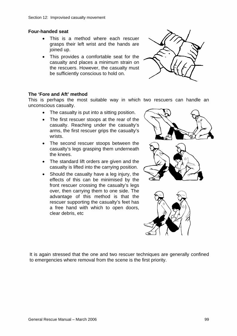
Section 12: Improvised casualty movement
General Rescue Manual – March 2006 99
Four-handed seat • This is a method where each rescuer
grasps their left wrist and the hands are joined up.
• This provides a comfortable seat for the casualty and places a minimum strain on the rescuers. However, the casualty must be sufficiently conscious to hold on.
The ‘Fore and Aft’ method This is perhaps the most suitable way in which two rescuers can handle an unconscious casualty.
• The casualty is put into a sitting position. • The first rescuer stoops at the rear of the
casualty. Reaching under the casualty’s arms, the first rescuer grips the casualty’s wrists.
• The second rescuer stoops between the casualty’s legs grasping them underneath the knees.
• The standard lift orders are given and the casualty is lifted into the carrying position.
• Should the casualty have a leg injury, the effects of this can be minimised by the front rescuer crossing the casualty’s legs over, then carrying them to one side. The advantage of this method is that the rescuer supporting the casualty’s feet has a free hand with which to open doors, clear debris, etc
It is again stressed that the one and two rescuer techniques are generally confined to emergencies where removal from the scene is the first priority.

Section 13: Anchors and holdfasts
100 General Rescue Manual – March 2006
13 Anchors and holdfasts
13.1 Objectives On completion of training on this chapter of the General Rescue Manual, individuals should be able to:
• Construct a 3:2:1 picket holdfast • Describe the acceptable anchor angles
13.2 Introduction Anchors and holdfasts are used in rescue for the purpose of securing a line, rope, or wire that will be under load. They fall into three main classes:
• Natural - Trees and boulders • Constructed - Those that have to be set up (eg. by use of pickets and
lashings, anchor devices, buried baulks, or timber) • Improvised - Those found on the site, (eg. Reinforced concrete or metal
standards, metal framework of buildings, baulks of timber across door openings, etc).
13.3 Natural anchors The most readily identifiable anchor points are trees, large rocks, and spikes of rock. These must be carefully selected, with regard to load and direction of load. These points should not be too close to risk areas and must be tested by a hauling crew before use.
13.4 Constructed anchors Picket holdfasts Pickets are suitable as anchors. It is recommended they be placed into a holdfast system. These can be arranged as:
• 1 : 1 or • 2 : 1 or • 3 :2: 1 system, according to the situation.
The following points should be observed:
• The pickets should be driven into the ground at about 90 degrees to the line of pull, at an approximate angle of 45 degrees from ground level, leaning away
1:1
2:1
3:2:1

Section 13: Anchors and holdfasts
General Rescue Manual – March 2006 101
from the load, and with two-thirds of their length into the ground. • The strongest picket/s should be nearest the load. • The lashings connecting the pickets should be at 90 degrees to the pickets
and should go from the head of the one in the front to ground level on the one behind. This determines the distance between the pickets, which should be more than 700mm apart.
• Anchor systems should be monitored at all times. • As a rough guide to safe working loads a 1.5m x 25mm mild steel picket driven
into ground with good holding qualities will safely support a load of approximately 350kg.
• As the number of pickets in the holdfast is increased, the load it will support is increased by approximately 350kg for each picket.
NOTE: When using angle iron pickets, the V of the picket must face the load.
Padding must be used.
From above the picket placement for the 3:2:1 picket holdfast (before lashing) look like:
Load
Placement of pickets
• Pickets are placed either using heavy hammers or impact drivers. • Pickets should be positioned and held by two rescuers, each holding one end
of a short cord taken around the picket in a Clove hitch, whilst a third rescuer hammers the picket into the ground.
• Rescuers must wear safety glasses/goggles and leather gloves. • Picket drivers can be used. These are simply a tube with handles attached
and used in place of hammers to drive the picket by impact.
Picket removal • Pickets can be removed from most placements with a large Stilson or pipe
wrench. • The wrench is fitted to the shaft of the picket and used to wind the picket
around and out of the ground as the rescuer exerts an upward pressure on the wrench handle.
NOTE: For angle iron V pickets, reverse hammering, leverage or high lift jacks are
suitable for removal.

Section 13: Anchors and holdfasts
102 General Rescue Manual – March 2006
Picket lashings
• Each lashing is formed using a 12m rope. • The lashing should be started by a clove hitch about 180mm from the head of
the front picket. • Four turns should be taken around the base of the back picket and the head of
the front picket, placing these above the clove hitch. • Turns should be applied around the lashing, (known as frapping turns)
finishing with a clove hitch around the lashing, using up whatever spare rope is left.
• The lashing must be tightened before commencing the frapping turns. Ground anchor plates A number of designs for ground anchor plates exist but the principle is the same - using a series of long pins are used to anchor a plate onto the ground that can then be used as an anchor point, with a rated shackle or Karabiner attached to the front edge. LOAD Buried holdfasts With this holdfast, a stout piece of timber, a length of steel girder, a large diameter water pipe or a vehicle spare wheel is required.
• A trench is dug to accommodate the material used and a small outlet made at right angles to the trench to allow the rope or wire to come to the surface.
• The greater the load applied, the deeper the trench should be.
• The buried holdfast is only satisfactory where the angle between ground level and the rope is small.
• This being the case, the trench need not be filled in, but a rescuer should be detailed to check the holdfast when the initial load is applied.
• Where a round section of material such as a log or pipe is used for the buried holdfast, the positioning of the rope is critical.
• The rope should be taken around the holdfast so that the standing part comes to the bottom of the holdfast and the

Section 13: Anchors and holdfasts
General Rescue Manual – March 2006 103
running end comes off the top of the holdfast. • As the load is applied, this will tend to roll the holdfast down into the trench
rather than upwards. Log and picket holdfasts
• This heavy-duty anchor is set up with four pickets placed about 400–500mm apart and a second row of four pickets is placed 1m behind the first row.
• A log, beam, or other suitable section of material is laid behind the first row of pickets and each pair of pickets is lashed together.
• The log or beam then forms the anchor point for attaching the rope/system to.
• This method is of particular use in wet or soft earth since the log acts as a beam and bears evenly against the front row of pickets.
13.5 Improvised anchors When using an improvised holdfast (e.g. an electric light pole, a baulk of timber across a doorway, or a heavy vehicle), care should be exercised in assessing whether or not the item selected will in fact carry the load, and that it is correctly placed relative to the anticipated load.
13.6 Precautions in operations The following points should be observed in anchoring operations:
• Padding must be placed to protect anchors and slings. • Pickets should be of sound materials, preferably steel, correctly placed and
secured. • Anchors must be assessed as capable of sustaining the maximum anticipated
load in the appropriate load direction. • Any selected point must be tested in all appropriate load directions. • All anchor points, slings and attachments must be checked regularly
throughout the operation.
13.7 Selection of anchors Given the various types of anchors available, the selection of the most appropriate point or points must always be made on the basis of speed and simplicity. The first choice for anchorage should always be a large single point capable of sustaining the calculated maximum loading. Where no single point is sufficiently strong to sustain the load, two points can be brought together so that the load is evenly distributed between the two points.

Section 13: Anchors and holdfasts
104 General Rescue Manual – March 2006
13.8 Sling loading angles A two leg sling may be used to support or secure a load from separate anchor points. The forces involved form a direct relationship between load and attachment angle. The force increases on each leg the further apart they become, resulting in the anchors pulling against each other until failure occurs. As illustrated, when two legs of a sling system form an angle of 120 degrees, each leg supports 100% of the load. Increasing the angle further than 120 degrees magnifies the tension exponentially. At 150 degrees, the force on each leg is almost 200% of the original load. Care must be taken to minimise the internal angle of the slings in order to reduce magnification of the forces on the anchors. This principal also applies to ropes where they are used in an anchor system.
Angle between anchors
(a)
Resultant load on
each sling in kg (b)
Relative tension on each side relative to
load % 0 500.0 50.0
10 501.9 50.220 507.7 50.830 517.6 51.840 532.1 53.245 542.0 54.250 551.7 55.260 577.4 57.770 610.4 61.080 652.7 65.390 707.1 70.7
100 777.9 77.8110 871.7 87.2120 1000.0 100.0130 1183.1 118.3140 1461.9 146.2150 1931.9 193.2160 2879.4 287.9170 5736.9 573.7
Load (b) kg
Angle
1000 kg
Load (b) kg

Section 13: Anchors and holdfasts
General Rescue Manual – March 2006 105
Sling load angles
0
1000
2000
3000
4000
5000
6000
0 10 20 30 40 50 60 70 80 90 100 110 120 130 140 150 160 170 180
Angle between anchors (°)
Res
ulta
nt lo
ad o
n ea
ch s
ling
(kg)
DANGER ZONE
(Based on applied load of 1000 kg)
Operationally, 90 degrees is a safe relationship between the two legs of the system, and the smaller the angle, the lower the load on each leg. At an angle close to zero the load on each leg is around 50% of the original load, but care must be taken to ensure the load does not pendulum onto one of the anchors.
WARNING NOTE: The angle at which anchor slings meet must never be more than 120
degrees, and should preferably be less than 90 degrees.
13.9 Attachment to anchors Ropes may be tied off directly to anchors, providing that the anchor material is padded or will not damage the rope itself. Wherever possible, two independent anchor points should be used as the standard for any task, with the load equally shared between the points. Rescue anchors are most commonly set up with the load attached by means of climbing tape slings and rescue rated Karabiner. Sling attachment methods have a large effect on how safe a system is. The following picture from the Petzl technical work solutions manual 2004 shows just how much a sling can be de-rated by various ways of securing around an object. To extend the length of a webbing loop, karabiners or tape knots should be used. Forming a girth hitch, as seen as the first two methods in the diagram below, should be avoided.
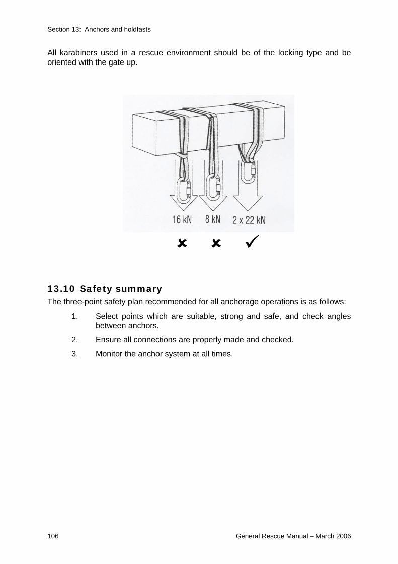
Section 13: Anchors and holdfasts
106 General Rescue Manual – March 2006
All karabiners used in a rescue environment should be of the locking type and be oriented with the gate up.
13.10 Safety summary The three-point safety plan recommended for all anchorage operations is as follows:
1. Select points which are suitable, strong and safe, and check angles between anchors.
2. Ensure all connections are properly made and checked.
3. Monitor the anchor system at all times.

Section 14: Pulley systems and lifting
General Rescue Manual – March 2006 107
14 Pulley systems and lifting
14.1 Objectives By the end of study and training on this chapter of the General Rescue Manual individuals should be able to:
• Construct a basic 3:1 pulley system
14.2 Introduction Pulley systems are used to gain a mechanical advantage in hauling, lifting and lowering operations. A system is formed by threading the pulleys with rope and all rescuers should be familiar with the correct terms, applications, capabilities and maintenance of this equipment. The traditional forming of ropes and pulleys into block and tackle systems has largely been overtaken by the more modern Z-rig pulley techniques utilising Kernmantel rescue ropes and lightweight high strength rescue pulleys.
14.3 Terminology Haul The act of pulling on the running end of the rope to operate the system. Mousing Securing the hook of a pulley by wrapping small diameter cord or duct/electrical tape. Pulley A sheave in a frame or shell, provided with a connection point by which it may be attached to another object. Redirection pulley A pulley used in a system to change the direction of the pull without affecting the mechanical advantage. Running end The free end of the rope to which the pulling power is applied. Running pulley The pulley attached to the object being moved. A pulley that travels up or down as the system is used.

Section 14: Pulley systems and lifting
108 General Rescue Manual – March 2006
Sheave The grooved wheel over which the rope is run in a pulley. Shell The frame or part of the pulley which holds the sheave and to which the strap, hook, or eye is attached. Snatch block A single sheave pulley with an opening or gate in one side of the shell, through which a rope can be engaged or ‘snatched’ into the sheave without threading the end of the rope through. This opening is secured by means of a hinged or pivoted portion of the strap. Standing block The system pulley which is fastened to an anchor. Strap or cheek The side plate of the pulley to which the hook or eye is attached. Swing cheek pulley A pulley design in which the side plates or cheeks can be pivoted on the axle to open the pulley and permit access for the rope to the sheave.
14.4 Types of pulleys The pulleys normally used in rescue systems are:
• Single sheave pulleys • Double or two sheave pulleys • Triple or three sheave pulleys • Snatch block
Sheave size and shape are important to safety. The diameter of the sheave must be such that the rope is not turned too sharply or it will be damaged, and particularly with steel wire ropes, the shape of the sheave groove must be correct for the rope.
14.5 Characteristics of the lightweight rescue pulley
Lightweight rescue pulleys should be of swing cheek design and have the following characteristics:
• The sheave should have a diameter at least four times the diameter of the rope.
• The cheek plates should be moveable so that the pulley can be placed on the rope at any point without having to feed the rope through.

Section 14: Pulley systems and lifting
General Rescue Manual – March 2006 109
They should also extend beyond the edge of the sheave to protect the rope from abrasion.
• The axle should have rounded ends which will not snag on ropes, other gear or objects.
• The bearings should be of such construction as to allow the sheave to turn freely when loaded.
• A rated strength in excess of 1500kg and preferably greater then 2500kg.
14.6 Constructing pulley systems A modern lightweight pulley system such as the 3:1 rig is best built in place. The load line is bought to the anchored pulley, passed through it, and forward to the moving pulley, through the moving pulley, and back to the running end.
14.7 Types of pulley systems A lifting system is one in which the load is attached to the running (lowest) pulley, and the running end coming off the standing or upper pulley. When calculating the capability of a lifting system, it must be realised that only the sections or rope between the pulleys assist in the lift, and that the running end does not help the lift at all. Power is applied to the running end, and in the opposite direction to the direction in which the load is to be moved. A hauling system is one in which the running end comes off the running pulley (to which the load is attached), and the standing pulley is attached to an anchor of appropriate capability.
14.8 Mechanical advantage The Theoretical Mechanical Advantage (TMA) of a pulley system can be calculated by counting the number of sheaves or the number of sections of rope running between the pulleys in the system. For a system involving five sheaves, the TMA would be expressed as being 5 to 1 (or 5:1). This is a very simplified method, but is sufficient for this level of knowledge.

Section 14: Pulley systems and lifting
110 General Rescue Manual – March 2006
For a 3:1 mechanical advantage, exerting 100kg of force on the running end will produce 300kg of force on the load. The flipside to this is that the rescuer needs to pull three metres of rope for the load to move just one metre. The Actual Mechanical Advantage (AMA) is less than the theoretical one due to the amount of friction caused by the ropes passing over the sheaves or contacting each other in the returns. The actual efficiency of the pulleys in the system is also taken into account.
14.9 Precautions in use The following safety factors must be observed when working with pulley systems:
• Pulley sheave sizes must be appropriate to the rope used. • The rope must be free from kinks and twists and must run easily over the
sheaves. • All fastenings must be securely made. • Pulley systems must be carried, never dragged on the ground. • All hooks must be properly moused with fitted catches. • Suspended weight must always be eased off gently and never lowered in
jerks. • Rescuers must haul or lower in unison, positioned on alternate sides of the
running end of the rope to keep the pull in a straight line using the hand over hand method.
• Sections of rope near the pulleys should not be touched when they are moving, as the rescuer’s hand may be trapped by the rope and drawn into the pulley.
• Not more than one tackle should ever be attached to either the load or the anchor sling.
• Pulleys must be well maintained, carefully handled and kept free of dirt and grit with all working parts sufficiently oiled to ensure free movement.
• Snatch blocks or single sheave blocks should be used on the running end of the system as redirection pulleys wherever possible. This will change the direction of haul to the horizontal, so that the rescue crew can work to best advantage.
• When using snatch blocks, check safety pins are secured. • All anchor points should be capable of supporting the total load involved.
14.10 Lift/Lower rope rescue devices A number of pre-rigged lift/lower rescue devices are readily available on the commercial rescue market. These systems operate either as traditional pulley rigs, or as friction drums or capstans. The devices are therefore categorised as either pulley systems or drum systems.

Section 14: Pulley systems and lifting
General Rescue Manual – March 2006 111
14.11 Commercial pulley systems These rigs are identical in design and operating principles to conventionally reeved pulleys, with the most common configuration being a 4:1 TMA. Several models are fitted with a rope brake cam in the shell of the anchored pulley, allowing for the final rope return to be secured between hauls. This cam can be ‘tripped’ by an accessory cord for lowering operations. Devices such as the ‘Rescue Master’ operate on the same principle but use a special inertial brake pulley. Systems such as the ‘Haulsafe’ and the ‘Rescuemate’ utilise lightweight rescue pulleys, and can readily be rigged with a length of rope that is appropriate to the most common application within the agency’s area of operations. The entire kit can then be stored and carried in a rope pack ready for deployment on all lift/lower/haul tasks.
14.12 Drum systems Drum controlled systems such as the ‘Griptech’ and the ‘Rollgliss’ provide friction for a controlled lower by means of the number of turns of rope formed around a rolling drum. They can be used with or without a travelling pulley, and in general provide a lower theoretical advantage for lifting/hauling than do the pulley systems.
14.13 Standard procedures for use • The device should be constructed with a length of rope which is sufficient for
normal applications in the area of response. This must take into account the rope required to form the returns required for the specific device.
• When used for life rescue purposes, the device should be rigged with rope that complies with New Zealand Standard AS4142.3:1993 - Static Rescue Lifelines.
• The devices must be used strictly in accordance with the manufacturer’s guidelines.
• These systems can be anchored overhead for direct lift/lower operations, or can be used for horizontal hauling. When used horizontally, additional care must be taken to ensure that the device is clear of all contact.
• Safety brakes or cams must be active or fitted for all lift/haul operations. • Standard procedures must be followed with respect to anchoring, crew
operations, commands and the wearing of gloves.
WARNING NOTE: For all mechanical winches, when steel wire rope (SWR) is under load, a
heavy blanket or similar should be placed across the rope so as to identify rope location and in case of failure of rope will assist as a rope brake.
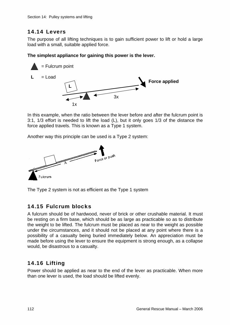
Section 14: Pulley systems and lifting
112 General Rescue Manual – March 2006
14.14 Levers The purpose of all lifting techniques is to gain sufficient power to lift or hold a large load with a small, suitable applied force. The simplest appliance for gaining this power is the lever.
= Fulcrum point
L = Load In this example, when the ratio between the lever before and after the fulcrum point is 3:1, 1/3 effort is needed to lift the load (L), but it only goes 1/3 of the distance the force applied travels. This is known as a Type 1 system. Another way this principle can be used is a Type 2 system:
The Type 2 system is not as efficient as the Type 1 system
14.15 Fulcrum blocks A fulcrum should be of hardwood, never of brick or other crushable material. It must be resting on a firm base, which should be as large as practicable so as to distribute the weight to be lifted. The fulcrum must be placed as near to the weight as possible under the circumstances, and it should not be placed at any point where there is a possibility of a casualty being buried immediately below. An appreciation must be made before using the lever to ensure the equipment is strong enough, as a collapse would, be disastrous to a casualty.
14.16 Lifting Power should be applied as near to the end of the lever as practicable. When more than one lever is used, the load should be lifted evenly.
L
3x 1x
Force applied

Appendix One:
General Rescue Manual – March 2006 113
15 Additional general rescue equipment
15.1 Objectives By the end of study and training on this chapter of the General Rescue Manual individuals should be able to: describe the usage and any relevant safety considerations for: Karabiner Shackles Generators Lighting
15.2 Introduction Most response teams will have a variety of other equipment that is intended for use in General Rescue and/or relating to areas of specialization, e.g. High Angle, Swift Water. This chapter is to introduce people to some of the common equipment being used. For specific information reference should be made to the manufacturer’s instructions. There is some equipment necessary for teams wanting to register as New Zealand Response Teams (NZ-RTs). Information on this equipment can be found on www.usar.govt.nz.
15.3 Karabiners Also known as ‘carabiners’, ‘krabs’ or ‘biners’ these are the most common item of hardware used in vertical rescue. They are normally a ‘D’ or modified ‘D’ shaped metal link, having a spring loaded opening section (the gate) in one of the long sides. The gate allows ropes and slings to be clipped into the Karabiner for attachment purposes.
Karabiners are manufactured from either high-tensile steel or alloy, and may have either a plain opening gate, or one fitted with a screw locking device or autolocking gate, which prevents the gate from accidental opening. Consequently, Karabiners are referred to as snaplinks, screwgates, twistlocks, or autolocks. NOTE: “Triple Action” Auto-locking Karabiners are considered to be ‘Best Practice’ in
rescue situations. Most manufacturers stamp the rated strength of the Karabiner into the metal for easy reference. Rescue Karabiners should be of minimum rated strength of 2500kg.
WARNING NOTE: Snaplink style Karabiners are NOT recommended for rescue.
Appendix One
114 General Rescue Manual – March 2006
As these devices are made of specialised steel or alloys, care should be taken not to drop them or knock them on hard surfaces. Small stress points can be introduced into the metal that may then cause deterioration of the device.
15.4 Accidental gate opening The main job of a Karabiner is to maintain its link with the other elements of the rescue system. To do this, the Karabiner gate must remain securely closed. If it does not, then the connecting elements will come apart and the system will fail. There are several ways in which Karabiner gates may come open accidentally. Among the most common situations are those where:
• The Karabiner is pressed against an edge or surface, forcing the gate open. • A rope or section of tape is pulled across the Karabiner gate, forcing it open.
15.5 Concerns with screwgate karabiners Any Karabiner that regularly becomes unlocked without apparent reason must be withdrawn from service. Screw gate Karabiners are designed to be locked only to finger tightness. In their concern for safety, and in some anxiety, people will tend to over-tighten a Karabiner gate, and then be unable to unlock it. This most commonly occurs when the gate is tightened while the Karabiner is under load. With some Karabiner designs, vibration can cause the gate locking sleeve to unscrew. Karabiners should always be used in a manner which will ensure that gravity will keep the sleeve in place.
15.6 Karabiner usage Karabiners are designed to be loaded along the major axis or spine. As previously stated, the gate is the weakest point of a Karabiner, and any side loading places an unnatural force on the Karabiner, severely reduces its strength, and may cause it to fail.
WARNING NOTE: Maximum strength is only achieved when the Karabiner gate is locked.
Karabiners must not be used unless the gate is properly closed and locked.
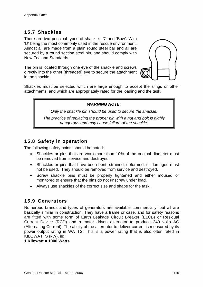
Appendix One:
General Rescue Manual – March 2006 115
15.7 Shackles There are two principal types of shackle: ‘D’ and ‘Bow’. With ‘D’ being the most commonly used in the rescue environment. Almost all are made from a plain round steel bar and all are secured by a round section steel pin, and should comply with New Zealand Standards. The pin is located through one eye of the shackle and screws directly into the other (threaded) eye to secure the attachment in the shackle. Shackles must be selected which are large enough to accept the slings or other attachments, and which are appropriately rated for the loading and the task.
WARNING NOTE: Only the shackle pin should be used to secure the shackle.
The practice of replacing the proper pin with a nut and bolt is highly dangerous and may cause failure of the shackle.
15.8 Safety in operation The following safety points should be noted:
• Shackles or pins that are worn more than 10% of the original diameter must be removed from service and destroyed.
• Shackles or pins that have been bent, strained, deformed, or damaged must not be used. They should be removed from service and destroyed.
• Screw shackle pins must be properly tightened and either moused or monitored to ensure that the pins do not unscrew under load.
• Always use shackles of the correct size and shape for the task.
15.9 Generators Numerous brands and types of generators are available commercially, but all are basically similar in construction. They have a frame or case, and for safety reasons are fitted with some form of Earth Leakage Circuit Breaker (ELCB) or Residual Current Device (RCD) and a motor driven alternator to produce 240 volts AC (Alternating Current). The ability of the alternator to deliver current is measured by its power output rating in WATTS. This is a power rating that is also often rated in KILOWATTS (kW), ie: 1 Kilowatt = 1000 Watts

Appendix One
116 General Rescue Manual – March 2006
15.10 ELCB’S and RCD’S These are commonly used terms to describe the same thing. All portable generators are built to minimise the possibility of electric shock. For portable single-phase generators, an acceptable safe configuration is either: • Option one
Floating (isolated) windings, without an ELCB/RCD. With an isolated winding there is no loss of power in the event of a single fault in the generator or in the load. Nor is there any indication of such fault. Accordingly, it is ideal for lighting. A person touching ‘live parts’ will receive no shock.
• Option two Polarised (frame connected) windings, with an ELCB/RCD With a frame connected winding plus RCD, a single fault on load-side equipment will trip the RCD and cause loss of power. A person touching the ‘live parts’ will receive a minor shock, but will be protected by the RCD.
Portable ELCBs/RCDs must be tested three (3) monthly as per AS3760. Other devices must be tested twelve (12) monthly. If frequently used in harsh or severe environments they should be tested at three (3) monthly intervals using the procedures set out in AS3760. 15.11 Power output of the generator Rescuers must know how to describe the amount of power that a particular appliance will draw so as not to overload the generator. Lights and heating appliances are normally rated in Watts.
• Therefore when using lights only, it is a simple matter to add the wattage of the number of lights being used and subtract the figure from the generator capacity to calculate the power still available.
• Example: 3 banks of lights, each drawing 500 Watts are being used: • TOTAL WATTAGE IS 1500 WATTS
Therefore, if a generator was rated at 2500 WATTS or 2.5kW, it can be seen that there is still 1000 Watts capacity left in the generator. Appliances using electric motors (eg: drills, chain saws, refrigerators, fans etc.) often indicate the amount of current drawn from the generator, not the power. This is usually found on a compliance plate on the appliance and is rated Amps. Example: An electric chain saw is rated at 5 Amps, the power it draws from the generator is: POWER (IN WATTS) = 240 VOLTS (normal mains power) x 5 AMPS = 1200 WATTS
Appendix One:
General Rescue Manual – March 2006 117
This particular chainsaw can be run from a 2500 Watt (2.5 kW) generator, but not from a 1000 Watt (1.0kW) generator.
• Rescue teams should calculate the power rating of each appliance likely to be used and clearly mark this figure in Watts on the appliance to save time and possible overload problems during an emergency.
WARNING NOTE: Motor starting current is approximately five times the rated full load current of electric motors. When selecting generators for motor starting, this factor
should be considered to avoid overloads.
15.12 Precautions in operations Any combination of heat, petrol, and electricity, creates a potentially dangerous situation. The following list of precautions should be observed when operating any generator.
• Do not place combustible material on or near the generator. • Operate the generator on a stable, level surface to prevent fuel spillage,
excessive vibration, and oil starvation. • During use, keep the generator at least 1 metre away from buildings and other
equipment. • Avoid placing anything around the generator, or covering it up. Generators
are normally air-cooled and require a free flow of air to prevent overheating. • Always stop the engine before refuelling. • Be careful not to spill fuel on the generator. If fuel is spilt, wipe the machine
dry before starting the engine. • Do not fill the fuel tank above the designated level. • Do not smoke when refuelling, or expose the process to naked flame. • Keep a suitable fire extinguisher nearby and upwind of the generator at all
times. • Do not operate the generator in or near locations with poor ventilation such as
tunnels, under houses, inside tents, etc. Carbon monoxide poisoning can rapidly result from a build up of exhaust gases.
15.13 Electrical safety precautions The electrical output of a generator is lethal. The following safety points should be observed:
• Keep the generator dry. Exercise great care when operating in wet conditions. • Never connect a generator to a household system.

Appendix One
118 General Rescue Manual – March 2006
• Coiled leads should be completely unwound before use. • On-the-job surveillance of all electrical equipment, particularly leads, is
essential. Checks must be made when stowing or withdrawing equipment from storage.
• Multiple outlets on floating generators are permitted if all equipment is double insulated or ‘equipotential’ bound.
• All inspection and testing of electrical equipment shall be carried out by a licensed electrician and in accordance with AS3760.
• All electrical equipment, including generators, leads, and fittings should be tested by a licensed electrician within each twelve (12) month period. The equipment must be tagged to indicate the date of inspection and name of the person inspecting.
15.14 Generator maintenance and regular checks Before operating any generator, read the manufacturers instructions and:
• Check sump oil level. • Ensure the correct fuel is used. • Use correct starting procedures. • Generators must be properly maintained to the manufacturer’s specifications if
reliable and long service is to be expected. • Generators should be run regularly under load.
15.15 Generator storage Many generators used by emergency services have periods where they may not be used for some considerable time. If this is the case:
• Store the generator with the piston in the compression stroke, thus closing both the inlet and exhaust valves and also closing the breaker points.
This procedure prevents corrosion of the combustion chamber, corrosion of the contact points and prevents the valves from sticking open when next the generator needs to be started. The compression stroke can be found by pulling the starter cord or turning the starter pulley until it becomes hard to turn (the piston is rising on the compression stroke), then continuing to turn the pulley until just before the top of the piston stroke.
• Drain the fuel from both the tank and the carburettor. Fuel left for long periods in the carburettor can cause a chemical reaction that adversely affects carburettor components.
Appendix One:
General Rescue Manual – March 2006 119
15.16 Lighting Working at night can increase the dangers involved with rescue work due to shadows, glare, and poor vision associated with artificial lighting systems. Rescuers should experience night rescue situations in training and experiment with various lighting arrangements, so as to eliminate as much as possible the three hazards mentioned.
15.17 Positioning lighting Little in the way of guidance can be given when lighting the rescue scene because all scenes vary greatly, but the following points are valid for most situations:
• Position lights as high as possible to illuminate the area required. • If working at heights, do not shine lights from below to illuminate the situation.
For example, rescuers on rooftops can suffer a temporary and unsafe loss of night vision by looking down into lights.
• If lights cannot be positioned above the scene, use hand lights or helmet mounted lights only, controlled by the rescuers working at that height.
• A rescuer who is temporary blinded or suffering a loss of night vision for any reason, should stay still and not move until night vision returns.
• A rescue scene is better illuminated with a soft, medium density light for movement within the area, with the particular work scene being illuminated with higher intensity lights such as spotlights.
• Position lights so that large shadows are minimised. • Keep lighting leads away from any dangerous area where damage is likely to
occur. • It can be useful to aim a spotlight through a window/opening to reflect the light
off the ceiling and walls – ensure window is not an entry/egress point.

Revision Sheet Tear off and return this sheet
120 General Rescue Manual – March 2006

Revision Sheet Tear off and return this sheet
General Rescue Manual – March 2006 121
As part of the process of ensuring the document remains current and in line with best practice, we welcome your feedback on all sections of this document. If you would like to provide feedback on the technical content of this manual, for consideration at revision, please fill out the form below and post to: Ministry of Civil Defence & Emergency Management PO Box 5010 WELLINGTON RE: General Rescue Manual – Feedback for revision
Where possible please reference the appropriate page (P), section (S) and subsection (ss). Ref. Comment Suggested Change/s
P S ss
Fold here

Revision Sheet Tear off and return this sheet
122 General Rescue Manual – March 2006
Ref. Comment Suggested Change/s
Please accept these comments as my suggestions for alteration/improvement of this manual at the next revision. Yours sincerely, Name:
Position:
Email Address:
Postal Address:
![IMMEDIATE Ministry of Defence [Acquisition Wing ... Make-II Procedure.pdfIMMEDIATE Ministry of Defence [Acquisition Wing Secretariat] Subject: Amendment to Defence Procurement Procedure](https://static.fdocuments.in/doc/165x107/5f0aea3d7e708231d42df762/immediate-ministry-of-defence-acquisition-wing-make-ii-immediate-ministry-of.jpg)