GENERAL REQUIREMENTS FOR SCADA AND AUTOMATION …inkoel.az/old/images/system_req.pdfPLC RTU SCADA...
62
Standard – Technical Specification STS 550 TRIM: HW2009-2368/2/31/.001 Warning – This document is current at time of printing or downloading. It may be reviewed and amended prior to the noted review date at the discretion of Hunter Water Corporation. Version: 1.0 Page 1 of 62 Date Approved: 181214 Hunter Water Corporation A.B.N. 46 228 513 446 Standard Technical Specification for: GENERAL REQUIREMENTS FOR SCADA AND AUTOMATION SYSTEMS STS550 This Standard Technical Specification was developed by Hunter Water Corporation to be used for the design, construction/installation and/or maintenance of facilities that are, or are to become, the property of Hunter Water Corporation. It is intended that this Standard Technical Specification be used in conjunction with various other standard and project specific drawings and design requirements as defined by Hunter Water Corporation for each particular project. Hunter Water Corporation does not consider this Standard Technical Specification suitable for use for any other purpose or in any other manner. Use of this Standard Technical Specification for any other purpose or in any other manner is wholly at the user's risk. Hunter Water Corporation makes no representations or warranty that this Standard Technical Specification has been prepared with reasonable care and does not assume a duty of care to any person using this document for any purpose other than stated. In the case of this document having been downloaded from Hunter Water Corporation's website; - Hunter Water Corporation has no responsibility to inform you of any matter relating to the accuracy of this Standard Technical Specification which is known to Hunter Water Corporation at the time of downloading or subsequently comes to the attention of Hunter Water Corporation. - This document is current at the date of downloading. Hunter Water Corporation may update this document at any time. Copyright in this document belongs to Hunter Water Corporation
Transcript of GENERAL REQUIREMENTS FOR SCADA AND AUTOMATION …inkoel.az/old/images/system_req.pdfPLC RTU SCADA...
Standard – Technical Specification STS 550 TRIM: HW2009-2368/2/31/.001
Warning – This document is current at time of printing or downloading. It may be reviewed and amended prior to the noted review date at the discretion of Hunter Water Corporation.
Version: 1.0 Page 1 of 62
Date Approved: 181214
Hunter Water Corporation A.B.N. 46 228 513 446
Standard Technical Specification for:
GENERAL REQUIREMENTS FOR SCADA AND AUTOMATION SYSTEMS
STS550
This Standard Technical Specification was developed by Hunter Water Corporation to be used for the
design, construction/installation and/or maintenance of facilities that are, or are to become, the property
of Hunter Water Corporation. It is intended that this Standard Technical Specification be used in
conjunction with various other standard and project specific drawings and design requirements as
defined by Hunter Water Corporation for each particular project.
Hunter Water Corporation does not consider this Standard Technical Specification suitable for use for
any other purpose or in any other manner. Use of this Standard Technical Specification for any other
purpose or in any other manner is wholly at the user's risk.
Hunter Water Corporation makes no representations or warranty that this Standard Technical
Specification has been prepared with reasonable care and does not assume a duty of care to any
person using this document for any purpose other than stated.
In the case of this document having been downloaded from Hunter Water Corporation's website;
- Hunter Water Corporation has no responsibility to inform you of any matter relating to the accuracy of
this Standard Technical Specification which is known to Hunter Water Corporation at the time of
downloading or subsequently comes to the attention of Hunter Water Corporation.
- This document is current at the date of downloading. Hunter Water Corporation may update this
document at any time.
Copyright in this document belongs to Hunter Water Corporation

Standard – Technical Specification STS 550 TRIM: HW2009-2368/2/31/.001
Warning – This document is current at time of printing or downloading. It may be reviewed and amended prior to the noted review date at the discretion of Hunter Water Corporation.
Version: 1.0 Page 2 of 62
Date Approved: 181214
1 Purpose .................................................................................................................. 7
2 Interpretation ......................................................................................................... 7
2.1 Order of Precedence ................................................................................................. 8
3 Roles and Responsibilities ................................................................................... 9
3.1 Document Owner ...................................................................................................... 9
3.2 Hunter Water Responsibilities.................................................................................... 9
3.3 Contractor Responsibilities ........................................................................................ 9
4 Definitions............................................................................................................ 10
5 General Requirements ........................................................................................ 11
5.1 Compliance and Regulatory .................................................................................... 11
5.1.1 Legislative Requirements ................................................................................. 11
5.1.2 Standards ........................................................................................................ 11
5.2 Quality Accreditation ............................................................................................... 11
5.3 Contractors ............................................................................................................. 11
5.4 Materials and Equipment ......................................................................................... 11
5.5 Computer Equipment .............................................................................................. 12
6 PLC ....................................................................................................................... 13
6.1 PLC hardware layout ............................................................................................... 13
6.2 PLC Software Layout .............................................................................................. 13
6.3 PLC Software .......................................................................................................... 13
6.4 PLC IP Address ....................................................................................................... 13
6.5 PLC Naming Conventions ....................................................................................... 14
6.5.1 PLC Program File ............................................................................................ 14
6.5.2 PLC Program ................................................................................................... 14
6.5.3 PLC Functional Group ..................................................................................... 15
6.5.4 PLC Hunter Water Function Block.................................................................... 15
6.5.5 Control Module ................................................................................................ 16
6.5.6 PLC Program Variable ..................................................................................... 16
6.5.7 PLC Program Structure.................................................................................... 17
6.6 PLC Code ............................................................................................................... 18
6.7 Project Specific Code .............................................................................................. 18

Standard – Technical Specification STS 550 TRIM: HW2009-2368/2/31/.001
Warning – This document is current at time of printing or downloading. It may be reviewed and amended prior to the noted review date at the discretion of Hunter Water Corporation.
Version: 1.0 Page 3 of 62
Date Approved: 181214
6.7.1 Project Specific Function Block naming convention .......................................... 19
6.8 Alarms .................................................................................................................... 19
6.9 Analog Alarms ......................................................................................................... 19
6.9.1 Digital Alarms .................................................................................................. 20
6.10 Program storage .................................................................................................. 20
6.10.1 PLC Code .................................................................................................... 20
6.10.2 SCADA Databases ...................................................................................... 20
6.10.3 SCADA Code............................................................................................... 20
6.11 Security ............................................................................................................... 21
6.11.1 Function Blocks ........................................................................................... 21
6.11.2 PLC ............................................................................................................. 21
6.11.3 SCADA ........................................................................................................ 21
7 Remote Telemetry Unit ....................................................................................... 22
7.1 RTU Hardware Layout ............................................................................................. 22
7.2 RTU Software ......................................................................................................... 22
7.3 RTU Code ............................................................................................................... 22
7.3.1 RTU Program File Naming Convention ............................................................ 22
7.4 RTU Addressing ...................................................................................................... 22
7.5 DNP3 ...................................................................................................................... 23
7.5.1 DNP3 Class 0 .................................................................................................. 23
7.5.2 Alarm structure and DNP3 classes................................................................... 23
8 SCADA ................................................................................................................. 24
8.1 SCADA Software ..................................................................................................... 24
8.2 SCADA Database Structure .................................................................................... 24
8.3 SCADA Point Naming Convention and Site Structure .............................................. 26
8.4 SCADA Template Configuration .............................................................................. 26
8.4.1 Common Templates ........................................................................................ 26
8.4.2 Non-commissioned Equipment ........................................................................ 28
8.5 SCADA Mimic/Screen Development ........................................................................ 28
8.5.1 Symbol Display Mimics .................................................................................... 28
8.5.2 Device Popup Mimics ...................................................................................... 29
8.5.3 Site Overview Mimics ...................................................................................... 29
8.6 SCADA Site Configuration ....................................................................................... 29

Standard – Technical Specification STS 550 TRIM: HW2009-2368/2/31/.001
Warning – This document is current at time of printing or downloading. It may be reviewed and amended prior to the noted review date at the discretion of Hunter Water Corporation.
Version: 1.0 Page 4 of 62
Date Approved: 181214
8.6.1 Telemetry Configuration................................................................................... 29
8.6.2 Titlebar Configuration ...................................................................................... 30
8.6.3 Point Data Population ...................................................................................... 30
8.6.4 SCADA Navigation Configuration ..................................................................... 30
8.7 Alarm ...................................................................................................................... 30
8.7.1 Alarm Data Population ..................................................................................... 31
8.7.2 Views .............................................................................................................. 32
8.8 Commissioning........................................................................................................ 32
9 HMI ....................................................................................................................... 33
9.1 HMI Software .......................................................................................................... 33
9.2 HMI Programming ................................................................................................... 33
9.2.1 Main Menu Page ............................................................................................. 34
9.2.2 HMI Plant Overview Page ................................................................................ 35
9.2.3 5.2.3 HMI Plant Status Page ............................................................................ 35
9.2.4 HMI Plant Power Supply Page ......................................................................... 37
9.2.5 HMI VSD Page ................................................................................................ 38
9.2.6 HMI Alarm Page .............................................................................................. 39
10 CONTROL NETWORK DESIGN ........................................................................... 40
10.1 SCADA and Control Network Architecture ........................................................... 40
10.2 Treatment Plants ................................................................................................. 41
10.2.1 Control I/O ................................................................................................... 41
10.3 Pumping Stations ................................................................................................ 41
11 COMMUNICATIONS ............................................................................................. 42
11.1 Network Assets ................................................................................................... 42
11.1.1 NextG/ Licensed Digital Radio ..................................................................... 42
11.1.2 900MHz point to point digital radio ............................................................... 42
11.1.3 450MHz Analog UHF/Radio ......................................................................... 42
11.2 Telemetry - Treatment Plants.............................................................................. 42
11.3 DNP3 .................................................................................................................. 42
11.4 PLC to RTU communications ............................................................................... 43
11.5 PLC to remote device communications ................................................................ 44
11.6 Peer-to-Peer communications.............................................................................. 44
11.6.1 Radio Network ............................................................................................. 44

Standard – Technical Specification STS 550 TRIM: HW2009-2368/2/31/.001
Warning – This document is current at time of printing or downloading. It may be reviewed and amended prior to the noted review date at the discretion of Hunter Water Corporation.
Version: 1.0 Page 5 of 62
Date Approved: 181214
11.6.2 NextG Network ............................................................................................ 44
11.6.3 Alternative peer to peer communication ....................................................... 44
12 Related Documents ............................................................................................. 45
13 Document Control ............................................................................................... 46
FIGURES
Figure 1 Example- PLC Functional Group Naming ................................................................................. 15
Figure 2: PLC Program Structure ........................................................................................................... 17
Figure 3: HMI Main Menu Page ............................................................................................................. 34
Figure 4: HMI Plant Overview Page ....................................................................................................... 35
Figure 5: HMI Plant Status Page ............................................................................................................ 36
Figure 6: HMI Plant Power Supply Page ................................................................................................ 37
Figure 7: HMI VSD page ........................................................................................................................ 38
Figure 8: HMI Alarm Page ..................................................................................................................... 39
Figure 9: Control Network ...................................................................................................................... 40
TABLES
Table 1: DNP3 Alarm Class ................................................................................................................... 23
Table 2: SCADA Database Structure ..................................................................................................... 25
Table 3: SCADA Full Point Names ......................................................................................................... 26
Table 4: Equipment Template Names .................................................................................................... 27
Table 4: SCADA Alarms ........................................................................................................................ 31

Standard – Technical Specification STS 550 TRIM: HW2009-2368/2/31/.001
Warning – This document is current at time of printing or downloading. It may be reviewed and amended prior to the noted review date at the discretion of Hunter Water Corporation.
Version: 1.0 Page 6 of 62
Date Approved: 181214
APPENDICIES
Appendix A. Example PLC Function Block Documentation ............................... 47
Appendix B. Sample PLC Code Layout ................................................................ 52
Appendix C. HMI Screen Configuration ............................................................... 55
Appendix D. Variable Descriptors Table .............................................................. 62

Standard – Technical Specification STS 550 TRIM: HW2009-2368/2/31/.001
Warning – This document is current at time of printing or downloading. It may be reviewed and amended prior to the noted review date at the discretion of Hunter Water Corporation.
Version: 1.0 Page 7 of 62
Date Approved: 181214
Standard Technical Specification
General Requirements for SCADA and
Automation Systems – STS 550
1 Purpose
This document describes Hunter Water requirements for the configuration and programming of the
SCADA and Automation systems. The scope includes:
PLC
RTU
SCADA
HMI
Control Network Layout
Communications and Telemetry
All work shall comply with this standard using the software packages and versions as defined by Hunter
Water.
Hunter Water shall not be bound to check any documents or software code submitted for errors,
omissions or compliance with the requirements of the specification or standards.
All code produced for Hunter Water remains the property of Hunter Water. Hunter Water retains the right
to refuse the use of code due to any non-conformance.
2 Interpretation
For the purposes of this Standard Technical Specification, except where the context requires otherwise:
'Drawings' means the drawings detailing the work involved in the particular project in hand.
‘Include’ means including but not limited to, and is used to provide clarification or examples of the
type and nature of items intended
'Specification' means the Specification detailing the work involved in the particular project in hand.
‘Code’ means the software programs related to the particular project in hand.
Standards’ means applicable industry standards include the Australian Standards (AS),
Australian / New Zealand Standards (AS/NZS), American National Standards Institute (ANSI) and
ISO Standards (ISO)
'Standard Drawings' means the Hunter Water Corporation drawings
'Standard Technical Specifications' means the Hunter Water Corporation technical specifications.

Standard – Technical Specification STS 550 TRIM: HW2009-2368/2/31/.001
Warning – This document is current at time of printing or downloading. It may be reviewed and amended prior to the noted review date at the discretion of Hunter Water Corporation.
Version: 1.0 Page 8 of 62
Date Approved: 181214
'Standard Code' means the Hunter Water Corporation standard code libraries.
Headings are for the convenience of the reader and shall not be used in the interpretation of this
Standard Technical Specification.
Specific requirements, including those in the Specification or Drawings, take precedence over general
requirements.
Unless the context requires otherwise any expression such as "give notice", "submit", "approval", or
"directed" means give notice to, submit to, approval by, or directed by the person nominated by the
Principal or Purchaser.
Approval does not imply acceptance of responsibility by Hunter Water for compliance with this technical
specification. Unless approval has been issued in writing approval has not been granted.
Failure to comply with the requirements of this specification or any referred documentation may result in
rejection. Where equipment and / or manufacture are rejected, notice will be given by Hunter Water in
writing. All associated rectification work shall be completed by the Contractor at their cost.
2.1 Order of Precedence
Specific requirements, including those in project specifications or Standard Drawings take precedence
over this Standard Technical Specification. Any deviation from this Standard Technical Specification shall
be approved in writing on a case by cases basis by Hunter Water’s Document Owner.
Standard – Technical Specification STS 550 TRIM: HW2009-2368/2/31/.001
Warning – This document is current at time of printing or downloading. It may be reviewed and amended prior to the noted review date at the discretion of Hunter Water Corporation.
Version: 1.0 Page 9 of 62
Date Approved: 181214
3 Roles and Responsibilities
3.1 Document Owner
The document owner of this STS is the Hunter Water Manager Asset Management.
3.2 Hunter Water Responsibilities
Any request for a variation to STS550 shall be made in accordance with the change management
process in Hunter Water Asset Standards Management Plan.
The Document Owner shall approve in writing the issue of any updated version of STS550.
3.3 Contractor Responsibilities
Ensure that all; works carried out complies with relevant Hunter Water standards. Where a non
compliance is required, approval shall be obtained from the STS Document Owner.
Standard – Technical Specification STS 550 TRIM: HW2009-2368/2/31/.001
Warning – This document is current at time of printing or downloading. It may be reviewed and amended prior to the noted review date at the discretion of Hunter Water Corporation.
Version: 1.0 Page 10 of 62
Date Approved: 181214
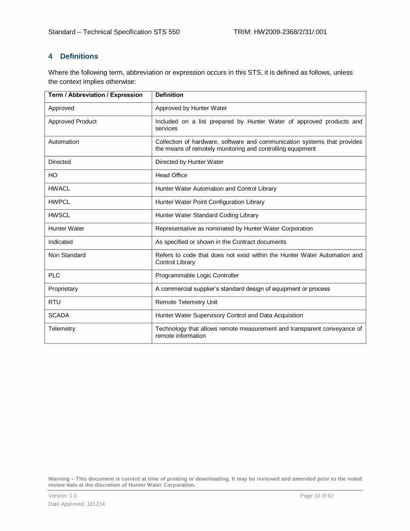
4 Definitions
Where the following term, abbreviation or expression occurs in this STS, it is defined as follows, unless
the context implies otherwise:
Term / Abbreviation / Expression Definition
Approved Approved by Hunter Water
Approved Product Included on a list prepared by Hunter Water of approved products and services
Automation Collection of hardware, software and communication systems that provides the means of remotely monitoring and controlling equipment
Directed Directed by Hunter Water
HO Head Office
HWACL Hunter Water Automation and Control Library
HWPCL Hunter Water Point Configuration Library
HWSCL Hunter Water Standard Coding Library
Hunter Water Representative as nominated by Hunter Water Corporation
Indicated As specified or shown in the Contract documents
Non Standard Refers to code that does not exist within the Hunter Water Automation and Control Library
PLC Programmable Logic Controller
Proprietary A commercial supplier’s standard design of equipment or process
RTU Remote Telemetry Unit
SCADA Hunter Water Supervisory Control and Data Acquisition
Telemetry Technology that allows remote measurement and transparent conveyance of remote information

Standard – Technical Specification STS 550 TRIM: HW2009-2368/2/31/.001
Warning – This document is current at time of printing or downloading. It may be reviewed and amended prior to the noted review date at the discretion of Hunter Water Corporation.
Version: 1.0 Page 11 of 62
Date Approved: 181214
5 General Requirements
5.1 Compliance and Regulatory
In addition to STS550, all work shall comply with the relevant:
Legislative Requirements
o Australian federal, state and local government legislation
o Codes of Practice
Standards
Hunter Water Standard Technical Specifications
5.1.1 Legislative Requirements
The relevant Commonwealth and New South Wales (NSW) legislation and Local Council Requirements
shall apply to all SCADA and automation equipment supplied to and operated by Hunter Water.
The Designer, Manufacturer, Supplier, and Installer shall be familiar with the requirements of:
The Work Health and Safety (WHS) Act, NSW, 2011 (WHS Act),
Work Health and Safety Regulation, NSW, 2011 (WHS Regulation) and
NSW WorkCover Codes of Practice
Key aspects of these legislative requirements are provided in STS 600 General Mechanical
Requirements, Section 5.1.
5.1.2 Standards
Any Standards relevant to SCADA and automation equipment supplied to and operated by Hunter Water
shall apply, including specific Standards or suites of applicable Standards referenced in STS500.
5.2 Quality Accreditation
Any SCADA and automation equipment should be designed, manufactured, and where practicable,
installed and commissioned by an organisation with a quality management system accredited as
compliant with ISO 9001:2008 Quality management systems — Requirements.
5.3 Contractors
Use only contractors listed on the Hunter Water Approved Contractors List available on the Hunter Water
Corporations website on www.hunterwater.com.au.
5.4 Materials and Equipment
Use only equipment and materials listed on the Hunter Water Approved Products and Manufacturers List
-Electrical available on the Hunter Water website:
Standard – Technical Specification STS 550 TRIM: HW2009-2368/2/31/.001
Warning – This document is current at time of printing or downloading. It may be reviewed and amended prior to the noted review date at the discretion of Hunter Water Corporation.
Version: 1.0 Page 12 of 62
Date Approved: 181214
www.hunterwater.com.au
All materials and equipment used shall be from items stocked within Australia and shall be from local
suppliers within the Newcastle region who provide support services for their products.
Where items are described by reference to a trade brand name or catalogue number, such a description
is intended to indicate the type, quality, appearance and method of construction required. An item of a
similar or equal standard may be incorporated in the works, subject to written Approval.
5.5 Computer Equipment
Computers used for software development shall have adequate and current anti-virus software and all
operating system security patches shall be within 2 weeks of manufacturer’s release.

Standard – Technical Specification STS 550 TRIM: HW2009-2368/2/31/.001
Warning – This document is current at time of printing or downloading. It may be reviewed and amended prior to the noted review date at the discretion of Hunter Water Corporation.
Version: 1.0 Page 13 of 62
Date Approved: 181214
6 PLC
Remote (outside treatment plant or pumping station) downloading or modification of the program
configuration of a PLC is not permitted
6.1 PLC hardware layout
For treatment plants, the PLC hardware will be selected to meet the site / project requirements.
For pumping stations, the standard PLC hardware used is detailed within the Hunter Water drawing sets
and is available from Hunter Water upon request.
6.2 PLC Software Layout
PLC programs, as a minimum, will:
Comply with all requirements within this document
Be neatly and logically arranged
Have all code well-spaced
Have detailed documentation that describes functionality of the code
Have a comment block placed at the beginning of each page. It will contain section name, code
designer name, date, version number and an overview of code operation
Have each functional area on the page separated by a header (comment block) that contains the
name of the functional area and is to be equal in width to the code being produced as a minimum
Where code requires additional comments, comments are to be placed above the area of code
where appropriate
Have variable names displayed in full, blocks and interconnecting lines not overlapping
An example of code layout is provided in Appendix B – Sample PLC Code Layout
6.3 PLC Software
Use the Current version of Unity Pro. Where a later version of Unity Pro is released during the term of a
contract, and this new version has been released for a minimum of three calendar months, then at the
time of final commissioning the latest version shall be used.
6.4 PLC IP Address
The PLC IP Address will be provided by Hunter Water.

Standard – Technical Specification STS 550 TRIM: HW2009-2368/2/31/.001
Warning – This document is current at time of printing or downloading. It may be reviewed and amended prior to the noted review date at the discretion of Hunter Water Corporation.
Version: 1.0 Page 14 of 62
Date Approved: 181214
6.5 PLC Naming Conventions
6.5.1 PLC Program File
PLC program file name is to conform to the naming convention described below:
<Facility Equipment Number>.sta
<Facility Equipment Number>.dtx
<Facility Equipment Number>.stu
Examples:
Burwood Beach WWTW, equipment name/number is STBUR. PLC file names will be:
o STBUR.sta
o STBUR.dtx
o STBUR.stu
Mayfield 2 WWPS, equipment name/number is SSMAY460. PLC file names will be:
o SSMAY460.sta
o SSMAY460.dtx
o SSMAY460.stu
Hunter Water will provide the equipment name/number.
6.5.2 PLC Program
The PLC project name shall use <Facility Equipment Number) format as described above.
The comment field of the PLC project shall display the first line as <Facility Name>. Subsequent lines
may describe any particular feature of that project or shall be left blank.
Examples:
o Project Name
o STBUR
o Project Comment:
o Burwood Beach WWTW
o Project Name
o SSMAY460
o Project Comment:
o Mayfield 2 WWPS

Standard – Technical Specification STS 550 TRIM: HW2009-2368/2/31/.001
Warning – This document is current at time of printing or downloading. It may be reviewed and amended prior to the noted review date at the discretion of Hunter Water Corporation.
Version: 1.0 Page 15 of 62
Date Approved: 181214
6.5.3 PLC Functional Group
The PLC functional groups are defined as follows
System - contains I/O mapping and communications routines between the PLC and other devices
Setup - contains PLC parameter setup
Process Area – Process Area is the top logical level for the treatment process. It contains the
following hierarchical levels: Cells, Units, Equipment Modules and Control Modules
Figure 1 Example- PLC Functional Group Naming
In the above example:
Inlet Works contains Inflow Balance Tank, Screenings, and Grit Removal Units.
The Screenings Unit contains equipment modules such as Screen Conveyor 1 and Screen
Conveyor 2.
Screen Conveyor 1 contains the basic control modules such as sensors and motors.
6.5.4 PLC Hunter Water Function Block
All Function Blocks within HWACL use the following naming convention:
HUNTER WATER_<Function Name>
Example : HUNTER WATER_VSD
Cell
(Inlet Works)
Unit
(Screenings)
Equipment
(Screen Conveying 1)
Control Module
(Screen Conveyor 1)

Standard – Technical Specification STS 550 TRIM: HW2009-2368/2/31/.001
Warning – This document is current at time of printing or downloading. It may be reviewed and amended prior to the noted review date at the discretion of Hunter Water Corporation.
Version: 1.0 Page 16 of 62
Date Approved: 181214
6.5.5 Control Module
Control Modules represent a single entity built up of sensors, actuators and control equipment. A Control
Module may represent:
An item of equipment, e.g. a motor, a valve, a temperature transmitter, etc, or
A software object, which is used for regulatory control or other control functions, e.g. a PID loop,
a timer or a counter.
PLC variable names are available on the P&ID.
Where a Function Block of a control module is created, the following naming convention shall be used:
Device name <P & ID Tag Number>
o Example: MF1203
MF is Control Module identifier (Motor Fixed-Speed)
1203 is the P&ID tag number
For Water and Waste Water Pumping Stations, the P&ID tag number is not available. Use the same
naming convention, replacing the P&ID tag number with an appropriate 4 digit number.
Example: Pump1 = PU0001
6.5.6 PLC Program Variable
PLC variable names shall use the Control Module names identified on the P&ID .
Example: MV1234 is the PLC variable name for Variable Speed Drive 1234.
The function of Control Module pins shall be identified in the Control Module Function Block.
6.5.6.1 PLC Variable Comments
All variables created are to include a detailed description of their functions. This includes both exposed
and internal Function Block variables. This comment should also include applicable engineering units,
where applicable.
For Booleans, this comment shall indicate the state of the variable when its value is 1 (TRUE)
Example: 1 = pump running
A table of descriptors is provided in Appendix D – Variable Descriptors table.
6.5.6.2 Naming of DDT elements
Where a variable is from physical I/O, the DDT element naming shall use names as referenced in the
electrical drawing set. All all letters in the variable name are in upper case.
Example: PU0001_CONTACTOR (Pump 1 Contactor 1 = Closed)
PU0001_RUN (Pump 1 Run Relay Output 1 = Run)

Standard – Technical Specification STS 550 TRIM: HW2009-2368/2/31/.001
Warning – This document is current at time of printing or downloading. It may be reviewed and amended prior to the noted review date at the discretion of Hunter Water Corporation.
Version: 1.0 Page 17 of 62
Date Approved: 181214
Where an internal variable without a physical connection to the block is used, the variable is to be
addressed using the Function Block name as the reference. If the name is more than one word, the
Function Block name shall be written as a single word with the first letter of each wrd un upper case.
Example: MV0001.SpeedReference
6.5.7 PLC Program Structure
An example of the required program structures are as follows:
Treatment Plant PLC Functional View
Pumping Station PLC Functional View
Figure 2: PLC Program Structure

Standard – Technical Specification STS 550 TRIM: HW2009-2368/2/31/.001
Warning – This document is current at time of printing or downloading. It may be reviewed and amended prior to the noted review date at the discretion of Hunter Water Corporation.
Version: 1.0 Page 18 of 62
Date Approved: 181214
6.6 PLC Code
Hunter Water has a Standard Code Library (HWSCL) to standardised PLC programming and SCADA. All
code within this library shall be made available on request.
The library has two sections:
HWACL – Automation and Control Library
HWPCL – Point Configuration Library
A list of the Function Blocks and templates within the library and the above files can be requested from
Hunter Water at:
The HWPCL contains all mapped addresses between the PLC,RTU and SCADA. For treatment plants,
this must be filled out and provided to Hunter Water.
All PLC Function Blocks (except communications blocks) are matched to a corresponding template in
SCADA. The documentation provided with each block will detail its corresponding template.
All Function Blocks are Read Only. Read Only is provided for debugging only. Read Only programs are
not provided as a basis for programming of additional blocks.
An example of the type of information that will be provided by Hunter Water is available in Appendix A –
Example PLC Function Block Documentation
6.7 Project Specific Code
Function Blocks may be developed if the required code does not exist within the HWSCL. As a minimum:
Approval is required prior to code development
Code will be placed inside a Function Block
The first routine in each block shall be structured text. This routine shall be called ‘Main’ and shall
contain revision history for the block as well as detailed block information (as per block
documentation). It shall not to contain code.
The new Function Block may contain Function Blocks from the default unity library. Where code
is required from an existing Hunter Water Function Block, the code will be made available. The
Hunter Water Function Block is not to be used inside a new Function Block.
The code will only use the following IEC61131 programming formats listed below. These formats
are presented in order of usage preference.
o Function Block
o Structured Text
o Sequential function chart
Positive logic is to be used
Use integrate simulation code inside Function Blocks where possible

Standard – Technical Specification STS 550 TRIM: HW2009-2368/2/31/.001
Warning – This document is current at time of printing or downloading. It may be reviewed and amended prior to the noted review date at the discretion of Hunter Water Corporation.
Version: 1.0 Page 19 of 62
Date Approved: 181214
Display all required inputs and outputs required for code debugging
Internal naming shall meet the requirements of STS 550
Each functional area within the Function Block shall be:
o Separated by a header that contains the name of the functional area and comments on
the code operation
o At minimum, equal in width to the code being produced.
Function Block comment shall briefly describe the Function Block operation
All variables within the Function Block are to include comments describing the operation of the
variable. . The comment should indicate the operation of the state of the variable. For example,
1 = healthy
Documentation shall use the template provided in Appendix A – Example PLC Function Block
Documentation
A corresponding SCADA template is required for Zone and Equipment blocks
6.7.1 Project Specific Function Block naming convention
For custom Function Blocks, the following naming convention shall be used:
CST_<Function Name>
o Example: CST_ABC
6.8 Alarms
Alarm categories are defined for the asset type by Hunter Water and shall be confirmed during the
development of the PLC program.
WWPS alarms defined below are provided for example only:
High – Intruder Alarm, AC Power Failure
Medium – No pumps available, wet well high level
Low – Pump health, Pump available
6.9 Analog Alarms
Alarms shall not be generated off set points within the PLC.
The analog value is mapped to the RTU and passed to the SCADA system where the alarms are
generated.
Alarms must be place within DNP3 classes as appropriate.

Standard – Technical Specification STS 550 TRIM: HW2009-2368/2/31/.001
Warning – This document is current at time of printing or downloading. It may be reviewed and amended prior to the noted review date at the discretion of Hunter Water Corporation.
Version: 1.0 Page 20 of 62
Date Approved: 181214
6.9.1 Digital Alarms
Digital alarms generated/received by the PLC must be assigned to the correct DNP3 class within the
RTU.
The DNP3 class is dictated by the priority of the alarm.
6.10 Program storage
6.10.1 PLC Code
6.10.1.1 Off Site
Prior to programming, a copy of the existing PLC Code shall be requested from Hunter Water.
During the project, operational circumstances may require Hunter Water to modify the existing PLC Code.
Should this occur, Hunter Water:
Should inform the programmer prior to modification of the existing PLC Code to minimise
interruption to the development of the new PLC Code.
Shall provide to the programmer the modified existing PLC Code and description and/or screen
shots of the modifications.
6.10.1.2 Pumping Station
Where an M340 is used in a pumping station, the station code will be backed up on the SD Card in the
front of the processor.
The SD Card does not automatically backup process data. The backup of process data must ensure the
plant control resumes in a safe manner. Where a new PLC is required, all %MWi values are to be reset to
zero before being restored from the backed up process data
Process data is to be backed up to the SD Card every 4 hours. Where SCADA process values exist, they
will take precedent over the values stored on the SD Card.
6.10.2 SCADA Databases
Redundant servers are used on the SCADA network.
Treatment Plant SCADA servers are backed up to an HO Server. This server maintains 1 year of data
and configuration for each Treatment Plant.
6.10.3 SCADA Configuration
Prior to modifying, a copy of the existing SCADA configuration shall be requested from Hunter Water.
During the project, operational circumstances may require Hunter Water to modify the existing SCADA
Code. Should this occur, Hunter Water:
Should inform the programmer prior to modification of the existing SCADA Code to minimise
interruption to the development of the new SCADA Code.

Standard – Technical Specification STS 550 TRIM: HW2009-2368/2/31/.001
Warning – This document is current at time of printing or downloading. It may be reviewed and amended prior to the noted review date at the discretion of Hunter Water Corporation.
Version: 1.0 Page 21 of 62
Date Approved: 181214
Shall provide to the programmer the modified existing SCADA Code and description and/or
screen shots of the modifications.
6.11 Security
6.11.1 Function Blocks
All code blocks within the HWACL are password protected and are Read Only
6.11.2 PLC
A Hunter Water 81.3 key is required for physical access to the PLC.
6.11.3 SCADA
Keys to access the SCX SCADA servers shall be issued on an as needs basis and shall be returned
upon project completion.

Standard – Technical Specification STS 550 TRIM: HW2009-2368/2/31/.001
Warning – This document is current at time of printing or downloading. It may be reviewed and amended prior to the noted review date at the discretion of Hunter Water Corporation.
Version: 1.0 Page 22 of 62
Date Approved: 181214
7 Remote Telemetry Unit
7.1 RTU Hardware Layout
For treatment plants, the RTU hardware will be arranged to meet the site requirements.
For Pump Stations, the standard RTU hardware layout is in the Hunter Water Standard Drawings. These
drawings are available from Hunter Water upon request. These drawings should be used as a reference
for hardware configuration of non Pump Station sites.
7.2 RTU Software
ISaGRAF – version 3.40 (Versions 5.x or 6.x shall not be used)
E-Series Configurator – version 8.05.6(minimum)
SCADAPack ISaGRAF Target library – version 3 only
7.3 RTU Code
Hunter Water shall provide two files that contain the full set of mapped addresses and two ISaGRAF
applications.
These files are contained within the HWACL
RTUs used within Pumping Stations shall contain both files
Where backup control is required, it must be enabled through the site parameter table within the
core functional group of the PLC.
The HWPCL contains all mapped addresses between the PLC,RTU and SCADA
7.3.1 RTU Program File Naming Convention
For the RTU files provided with the HWACL, the following naming convention will be adopted
<Equipment Number>.rtu
<Equipment Number>.uif
7.4 RTU Addressing
The RTU configuration file will be provided as part of the HWACL. The RTU requires an IP address and a
DNP address provided by Hunter Water

Standard – Technical Specification STS 550 TRIM: HW2009-2368/2/31/.001
Warning – This document is current at time of printing or downloading. It may be reviewed and amended prior to the noted review date at the discretion of Hunter Water Corporation.
Version: 1.0 Page 23 of 62
Date Approved: 181214
7.5 DNP3
DNP3 supports static data and event data:
Static data is called Class 0 data.
Event data can have a class or priority of 1, 2, or 3.
DNP3 supports several data types, e.g. “binary input” and “analog input”, and the corresponding events,
e.g. “binary input change” and “analog change”.
7.5.1 DNP3 Class 0
Class 0 data – static or current status of data.
To acquire all data and events, an integrity poll, partly consisting of a Class 0 poll is performed. Since a
large amount of data will be returned in a Class 0 scan, it should be performed the least often. Table 1
Section 7.5.2 indicates poll rates for each DNP3 class
7.5.2 Alarm structure and DNP3 classes
The alarm structure DNP3 classes shall be configured as follows:
Table 1: DNP3 Alarm Class
Class Class Description Event Type Event Buffer Size Poll Rate
0 Analogs are used for information only
e.g. rainfall, firmware version
Buffered N/A 4 h
1 All binary alarms
e.g. No available pumps
Unsolicited 1,000 30 min
2 All other binary and analog data
e.g. pump current, binaries that do not alarm
Buffered 1,000 2 h
3 Points that require faster updates on-screen
e.g. well level
Buffered 10 30 min
In addition:
All digital alarms will be unsolicited
Analogue alarm limits (e.g. 4 High) can be configured as unsolicited if required
The event deviation event is to be configured as buffered

Standard – Technical Specification STS 550 TRIM: HW2009-2368/2/31/.001
Warning – This document is current at time of printing or downloading. It may be reviewed and amended prior to the noted review date at the discretion of Hunter Water Corporation.
Version: 1.0 Page 24 of 62
Date Approved: 181214
8 SCADA
Hunter Water has developed a Standard Coding Library. Refer to Section 6.6 for details.
to ensure standardised programming of the SCADA system,
8.1 SCADA Software
The ClearSCADA application shall be maintained at not less than the first service release of the current
major version.
Following the release of a new major version is released, Hunter Water is unlikely to upgrade until the first
Service Pack of that major version is released.
Additional service releases (for the current major version) will be installed if required by Hunter Water to
address ‘bug’ fixes or to add new functionality that may be present in the service release.
8.2 SCADA Database Structure
The SCADA database structure is defined to ensure all database objects are managed within the
appropriate location. The main database is HO SCADA which monitors the whole network. For HO
SCADA, refer to the following table:

Standard – Technical Specification STS 550 TRIM: HW2009-2368/2/31/.001
Warning – This document is current at time of printing or downloading. It may be reviewed and amended prior to the noted review date at the discretion of Hunter Water Corporation.
Version: 1.0 Page 25 of 62
Date Approved: 181214
Table 2: SCADA Database Structure
Database Location Description
~Config SCADA Database configuration and settings as defined in the rows below
~Config.Comms Site communications channels
~Config.Colours Standard SCADA colours
~Config.Database Queries Database queries that SCADA relies on
~Config.Logic and Script Database-wide logic programs
~Config.Redirections Alarm redirection actions
~Config.Reports Database-wide reports
~Config.Schedules Database-wide schedule objects
~Config.Settings Custom configuration settings for database-wide functionality
~Config.Symbols Mimic symbols
~Config.Templates Database templates
~Config.Templates.Common SCADA only templates
~Config.Templates.Equipment Equipment templates matching PLC Function Block code
~Config.Templates.Proc Process level templates matching site-wide PLC Function Block code
~Config.Templates.Zone Site templates
~Config.Users Database users
~General Information Database-wide information and functionality
Bulk Distribution Bulk Distribution network sites
Bulk Source Bulk Source network sites
Coalfields Coalfields network sites
Dungog Shire Dungog Shire network sites
East Lakes East Lakes network sites
Newcastle Newcastle network sites
Not Commissioned Not Commissioned network sites
Port Stephens Port Stephens network sites
Weather Monitoring Weather Monitoring network sites
West Lakes West Lakes network sites
Worker Duress Worker Duress monitoring Burwood Beach Trial
WTP Water Treatment Plant sites
WWTW Wastewater Treatment Plant sites
Hunter Water shall approve new database groups.

Standard – Technical Specification STS 550 TRIM: HW2009-2368/2/31/.001
Warning – This document is current at time of printing or downloading. It may be reviewed and amended prior to the noted review date at the discretion of Hunter Water Corporation.
Version: 1.0 Page 26 of 62
Date Approved: 181214
8.3 SCADA Point Naming Convention and Site Structure
The SCADA site structure (treatment plants) is to reflect the program structure of the PLC.
A standard table of descriptors is provided in Appendix D – Variable Descriptors table. This table is to be
used for the creation of object names as detailed below.
SCADA sites (treatment plants) are created by instancing a site template inside the appropriate zone
group. Site templates are developed using approved equipment templates and reflect the program
structure of the PLC.
All full point names within SCADA require the following naming convention:
<Zone>.<Site>.<Equipment>.<Point>
Table 3: SCADA Full Point Names
Name Definition Example
<Zone> Group in the database structure the site is located Newcastle
<Site> The name of the site and the name of the site template instance Sandgate 2 WWPS
<Equipment> The name of the device on site and the name of the equipment template
instance
Pump 1
<Point> The name of the device attributes or database point Auto
This structure (from <Site> down) can be found within the HWACL.
Additionally, the “-” group contains points which are not displayed on a SCADA Mimic except via the
provided additional list. Any points added to the site instance must be added to these “-” groups.
8.4 SCADA Template Configuration
SCADA equipment templates are created and configured to match an appropriate PLC Function Block.
Site templates are then developed using a combination of equipment templates and additional common
(SCADA only) templates for further SCADA functionality.
Development of new SCADA Templates requires Approval.
8.4.1 Common Templates
SCADA common templates fulfil a variety of SCADA only functions. Many of which are used in site
template creation. e.g. A standard mimic title bar. The specific use of these common templates is defined
in the following sections.

Standard – Technical Specification STS 550 TRIM: HW2009-2368/2/31/.001
Warning – This document is current at time of printing or downloading. It may be reviewed and amended prior to the noted review date at the discretion of Hunter Water Corporation.
Version: 1.0 Page 27 of 62
Date Approved: 181214
8.4.1.1 Equipment Templates
SCADA equipment templates require the following structure convention:
<Template Name>.<Point>
Table 4: Equipment Template Names
Name Definition Example
<Template
Name>
The name of the name of the SCADA template object as well as the name
of the PLC Function Block
HUNTER
WATER_DOL_PUMP
<Point> The name of the device attributes or database point within the template that
refers to the appropriate PLC variable
Auto
Each equipment template requires the following:
An instance of the “Graphics” common template
o Any animated symbols, popups, faceplates, or other Mimics for the equipment template are to
be added to this “Graphics” instance
A “-” group
o Any points in the template which are not displayed on a popup or faceplate are to be located
within this group
Any Mimics developed must adhere to standards outlined in Section 8.5 SCADA Mimic/Screen
Development.
Property overrides for the new template shall be limited and only where appropriate.
8.4.1.2 Site Templates
SCADA site templates require the following structure convention:
<Template Name>.<Equipment Instance>.<Point>
Name Definition Example
<Template
Name>
The name of the SCADA template object HUNTER
WATER_ZONE_WWPS
<Equipment
Instance>
The name of the instanced equipment template used as part of the site Pump 1
<Point> The name of the device attributes or database point within the template
that refers to the appropriate PLC variable
Auto
Additional points that are required in the site template are to be added to the “-” group of each equipment
instance.

Standard – Technical Specification STS 550 TRIM: HW2009-2368/2/31/.001
Warning – This document is current at time of printing or downloading. It may be reviewed and amended prior to the noted review date at the discretion of Hunter Water Corporation.
Version: 1.0 Page 28 of 62
Date Approved: 181214
Each site template requires:
An instance of the “Graphics” common template, and within it the following:
o An instance of the “Titlebar” common template, named “Titlebar”
o A blank mimic named “Custom Content” where the “Document Content” property is property
overridden in the template
o A trend object named “Standard Trends”, configured with traces Hunter Water deems to be
standard for the site template
o A mimic named “Overview”, configured as the site overview mimic
Any Mimics developed must adhere to standards outlined in Section 8.5 SCADA Mimic/Screen
Development.
Property overrides for the new template shall be limited and only where appropriate.
8.4.2 Non-commissioned Equipment
Where only partial equipment has been permanently installed or allocated (in preparation for a future
expansion), the following applies:
The device and device indication is to be provided on the template in the correct position
All points are to be tested and commissioned as far as practical and then placed ‘Out of Service’.
Notes added to SCADA to detail expected availability dates for the device where possible.
Where equipment has been provisioned for but not installed, the following applies:
The device and device indication is to be provided on the template in the correct position
Indication of the devices (or devices) is to be shown as ‘greyed out’ objects.
All points, if any are to be placed ‘Out of Service’.
Notes added to SCADA device object to explain that this device is for future provisioning.
8.5 SCADA Mimic/Screen Development
The following are requirements for the development of Mimics:
8.5.1 Symbol Display Mimics
Symbols and device display Mimics require:
Colours shall be referenced to existing SCADA colour objects (~Config.Colours), where possible.
If the symbol or display contains functionality upon click, it must have a black outline or border if
clicking on the object results in anything other than a standard object menu.
‘Tahoma’ font.

Standard – Technical Specification STS 550 TRIM: HW2009-2368/2/31/.001
Warning – This document is current at time of printing or downloading. It may be reviewed and amended prior to the noted review date at the discretion of Hunter Water Corporation.
Version: 1.0 Page 29 of 62
Date Approved: 181214
8.5.2 Device Popup Mimics
Device popup and faceplate Mimics require:
The standard popup Titlebar symbol must be used
All value displays must use existing symbols
Colours shall be referenced to existing SCADA colour objects (~Config.Colours) where possible
‘Tahoma’ font
Embedded Mimics and symbols must retain their original size
8.5.3 Site Overview Mimics
Site overview Mimics require:
The “Display” mimic from the “Graphics.Titlebar” instance must be embedded at the top of the
page.
All items (except the sky and ground in a background layer) on the screen must have functional
significance. Only objects or devices that are monitored are to be displayed.
General site status displays are to be located to the left of the screen, animated symbols in the
centre, and the “Graphics.Custom Content” mimic embedded to the right of the screen (the
custom content mimic can be resized in the template to match the available space).
All value displays must make use of existing symbols
Colours shall be referenced to existing SCADA colour objects
‘Tahoma’ font
Embedded Mimics and symbols must retain their original size
8.6 SCADA Site Configuration
After instancing a Hunter Water site template to develop a new site, the following configurations are
required to ensure that all functionality is available.
8.6.1 Telemetry Configuration
The outstation object (RTU.Outstation) of a new site instance must be configured in order to match the
on-site hardware configuration. The following information supplied by Hunter Water must be configured:
The DNP address
The outstation Set
The network host address to the IP address
The majority of other fields should not be overridden.

Standard – Technical Specification STS 550 TRIM: HW2009-2368/2/31/.001
Warning – This document is current at time of printing or downloading. It may be reviewed and amended prior to the noted review date at the discretion of Hunter Water Corporation.
Version: 1.0 Page 30 of 62
Date Approved: 181214
8.6.2 Titlebar Configuration
Data is required within the new site instance in order for the “titlebar” to function correctly as follows:
Configure the Equipment Number (Identification tab) for the site instance object as provided by
Hunter Water. e.g. the “Sandgate 2 WWPS” template instance object.
Execute the “Update Equipment Number” logic located under “Graphics.Titlebar.Ellipse”.
Configure the “Hydraulic View” object (under “Graphics.Titlebar”) with a link to the hydraulic
overview object as provided by Hunter Water.
Configure the upstream and downstream network sites associated with the site (as provided by
Hunter Water) by populating the “Upstream” and “Downstream” string arrays (under
“Graphics.Titlebar”) with full names of the Overview Mimics for those sites.
8.6.3 Point Data Population
All points within the SCADA site that are associated with points in the PLC shall be populated with an
Equipment Number. Equipment Numbers for the point listing shall be provided by Hunter Water.
The Equipment Number configuration is found on the “Identification” tab of the properties of each point.
8.6.4 SCADA Navigation Configuration
Global sections of the SCADA database configuration need to be updated to allow navigation to and from
the site to be consistent with all other sites. The following is required:
The hydraulic symbol for the site (Graphics.Hydraulic) shall be embedded on the hydraulic
overview and displayed to align with other sites both horizontally and vertically, if applicable.
The main menu ($Root.Default) needs to be updated to provide navigation to the site. Configure
the advanced pick-action menu on the appropriate menu button to include a navigation hyperlink
to the overview (Graphics.Overview) of the new site. Ensure sites in the same graphical location
are grouped. E.g. Sandgate; and ensure the menu is displayed alphabetically.
8.7 Alarm
SCADA alarms are standard per device. Alarm and event severities shall be as defined in the template.
Hunter Water shall define alarm severities used for developing new templates. Alarm severities are:
Delayed Low
Delayed Medium
Delayed High
Low
Medium
High
Critical

Standard – Technical Specification STS 550 TRIM: HW2009-2368/2/31/.001
Warning – This document is current at time of printing or downloading. It may be reviewed and amended prior to the noted review date at the discretion of Hunter Water Corporation.
Version: 1.0 Page 31 of 62
Date Approved: 181214
If the severity of an alarm is deemed to be one of those that are delayed, the following extra configuration
must be completed once per point:
Alarm redirections must be enabled
A new redirection is to be configured as the following:
o Trigger Type: Auto
o Trigger State: Uncleared
o Action: ~Config.Redirections.Delay Time Change of Priority
o Low Severity: Delayed Low
o High Severity: Delayed High
o Direction: Either
o Delay: <Value provided by Hunter Water Corporation>
o Abort State: Cleared
o Active From: 00:00
o Active To: 00:00
When the severity of an alarm is configured, if the object is a DNP3 point, this will dictate the DNP3 class
the point is to be configured with. The following table shows the relationship between SCADA alarm
severity and DNP3 class data that is required.
Table 5: SCADA Alarms
SCADA Alarm Severity DNP3 Data Class RTU Event
Delayed Low 3 Enabled
Delayed Medium 2 Enabled
Delayed High 1 Enabled Unsolicited
Low 3 Enabled
Medium 2 Enabled
High 1 Enabled Unsolicited
Critical 1 Enabled Unsolicited
8.7.1 Alarm Data Population
All points within the SCADA site that are configured with an alarm shall include Action Text.
The Action Text configuration can be found on the “Alarm” tab of the properties of each point.
Action Text for the point listing shall be provided by Hunter Water.

Standard – Technical Specification STS 550 TRIM: HW2009-2368/2/31/.001
Warning – This document is current at time of printing or downloading. It may be reviewed and amended prior to the noted review date at the discretion of Hunter Water Corporation.
Version: 1.0 Page 32 of 62
Date Approved: 181214
8.7.2 Views
All points within the SCADA site that are configured with an alarm shall be configured with an Alarm View
and a Default View.
8.7.2.1 Alarm View
The Alarm View must be configured with the mimic or popup where the alarm is displayed.
The Alarm View configuration can be found on the “Alarm” tab of the properties of each point.
8.7.2.2 Default View
The Default View (inherited from the containing group) must be an overview for the site where the point is
located.
The Default View configuration can be found on the “Group” tab of the properties of the containing group
object.
8.8 Commissioning
The following items, at minimum, are required before the SCADA site can be moved from the “Not
Commissioned” group
Equipment Numbers
o All points that are associated with points in the PLC must have an Equipment Number
configured. This also includes the site Equipment Number.
Action Text
o All points that are configured with an alarm must have Action Text configured.
Network Links
o All upstream and downstream links for a site must be configured if applicable.
Views
o The Alarm View for each point must be mimic or popup where the alarm is displayed.
o The Default View for each point must be the overview for the site where the point is located.
Hydraulic View
o Each site must be configured with a Hydraulic View if applicable.
Menu Navigation
o Menus on the SCADA system must be configured to appropriately provide navigation to the
site.

Standard – Technical Specification STS 550 TRIM: HW2009-2368/2/31/.001
Warning – This document is current at time of printing or downloading. It may be reviewed and amended prior to the noted review date at the discretion of Hunter Water Corporation.
Version: 1.0 Page 33 of 62
Date Approved: 181214
9 HMI
Hunter Water uses HMI’s throughout the network. When using a HMI or remote terminal, the following
must be adhered to
Hunter Water has a working HMI project that should to be used as a basis for the creation of all
HMI screens. This HMI project can be provided upon request.
Where HMI's or remote terminals are to be used to provide diagnostic feedback to
operator/technicians, no user authentication is required.
9.1 HMI Software
Use the current version of Vijeo Designer.
Where a later version of Vijeo Designer is released during the term of a project, and the new version has
been released for a minimum of three calendar months, then at the time of final commissioning the latest
version shall be used.
9.2 HMI Programming
The basic project configuration process is as follows:
1. Hardware configuration (HMI and device IP addresses)
2. Configure real time clock for the HMI to be updated from the Plant PLC real time clock
3. Master Reference Variables configuration (used on Master Template pages)
4. Equipment Variables configuration (final device variables/addresses)
5. Master Template graphics pages (1 page per different type of device)
6. General graphics pages (main menu, plant status etc.)

Standard – Technical Specification STS 550 TRIM: HW2009-2368/2/31/.001
Warning – This document is current at time of printing or downloading. It may be reviewed and amended prior to the noted review date at the discretion of Hunter Water Corporation.
Version: 1.0 Page 34 of 62
Date Approved: 181214
9.2.1 Main Menu Page
The Menu page displays buttons used to navigate to other graphics pages for plant equipment.
The buttons on the Main Menu page are arranged in three groups, Plant, Power Monitoring and Devices.
Figure 3: HMI Main Menu Page

Standard – Technical Specification STS 550 TRIM: HW2009-2368/2/31/.001
Warning – This document is current at time of printing or downloading. It may be reviewed and amended prior to the noted review date at the discretion of Hunter Water Corporation.
Version: 1.0 Page 35 of 62
Date Approved: 181214
9.2.2 HMI Plant Overview Page
The Plant Overview page is s a quick reference page that displays the current general status and load of
all individual plant motor driven equipment.
Each item of equipment has a fault, ready and running status as well as load information.
The Plant Overview page has indication for each of the following general conditions of each drive:
“Fault” – Orange lamp indicates fault, Grey indicates no fault present.
“Ready” – Green lamp indicates ready (inputs to the TesysT or VSD combined with the internal
status of the TesysT or VSD), Grey indicates not ready.
“Run” – Red lamp indicates running, Grey indicates not running.
Note: “Ready” does not indicate that the drive is ready to start. It is a hardware indication that the field
input wiring to the TesysT or VSD is on AND the TesysT or VSD controllers are ready. It is not an
indication that the drive is ready for a PLC start.
Figure 4: HMI Plant Overview Page
9.2.3 5.2.3 HMI Plant Status Page
The Plant Status page displays the IDEA cycle setup and settings, the IDEA cycle state and the analogue
instrument readings. Settings cannot be changed and are for display purposes only.

Standard – Technical Specification STS 550 TRIM: HW2009-2368/2/31/.001
Warning – This document is current at time of printing or downloading. It may be reviewed and amended prior to the noted review date at the discretion of Hunter Water Corporation.
Version: 1.0 Page 36 of 62
Date Approved: 181214
The IDEA cycle setup has 2 modes (day or night). The current mode is indicated by a green
lamp.
The preset times for the cycle stages are shown for each mode and add up to 180 minutes.
The weir status is indicated by a green lamp.
Wet weather is indicated by a green lamp.
The IDEA cycle shows the current plant state with a green lamp.
The analogs group displays the reading of each instrument in as a number from 0-10000 (value sent to
SCADA).
Figure 5: HMI Plant Status Page

Standard – Technical Specification STS 550 TRIM: HW2009-2368/2/31/.001
Warning – This document is current at time of printing or downloading. It may be reviewed and amended prior to the noted review date at the discretion of Hunter Water Corporation.
Version: 1.0 Page 37 of 62
Date Approved: 181214
9.2.4 HMI Plant Power Supply Page
The Power Supply page displays power supply real-time readings of current, voltage, power, power factor
and harmonic distortion. No actions are available on this page.
Figure 6: HMI Plant Power Supply Page

Standard – Technical Specification STS 550 TRIM: HW2009-2368/2/31/.001
Warning – This document is current at time of printing or downloading. It may be reviewed and amended prior to the noted review date at the discretion of Hunter Water Corporation.
Version: 1.0 Page 38 of 62
Date Approved: 181214
9.2.5 HMI VSD Page
The VSD page below illustrates the typical setup for a Hunter Water VSD.
The VSD page displays general information about the VSD and the motor, Digital I/O, VSD status and
fault history.
On the Device Overview page indication is as follows
Grey/Green for Off/On for non-faults
Grey/Red for Off/On for fault indication
The fault history section shows the last 3 faults along with the time and date when they occurred.
Figure 7: HMI VSD page

Standard – Technical Specification STS 550 TRIM: HW2009-2368/2/31/.001
Warning – This document is current at time of printing or downloading. It may be reviewed and amended prior to the noted review date at the discretion of Hunter Water Corporation.
Version: 1.0 Page 39 of 62
Date Approved: 181214
9.2.6 HMI Alarm Page
The Alarms page is a standard in built System Error Log page. It will display in built system faults as well
as configured faults for each item of plant equipment.
Figure 8: HMI Alarm Page

Standard – Technical Specification STS 550 TRIM: HW2009-2368/2/31/.001
Warning – This document is current at time of printing or downloading. It may be reviewed and amended prior to the noted review date at the discretion of Hunter Water Corporation.
Version: 1.0 Page 40 of 62
Date Approved: 181214
10 CONTROL NETWORK DESIGN
10.1 SCADA and Control Network Architecture
Figure 9: Control Network
Figure 9: Control Network shows a typical layout of the SCADA and Control Network.
The green and red Ethernet networks are separate networks.
The green line represents SCADA domain communications connection.
The red line represents the Controls Network connection. Devices that can be controlled such as Drives,
Motor Starters, I/Os, are connected to a PLC Ethernet Module via Connexium switches. The PLC
communicates to the SCADA servers via a second and separate Ethernet Module / Port.
At some larger sites, the use of Fibre Optic Connectivity into the SCADA WAN may be used.
As some sites us of Analogue or Digital radio connectivity is used to connect into the SCADA WAN.

Standard – Technical Specification STS 550 TRIM: HW2009-2368/2/31/.001
Warning – This document is current at time of printing or downloading. It may be reviewed and amended prior to the noted review date at the discretion of Hunter Water Corporation.
Version: 1.0 Page 41 of 62
Date Approved: 181214
10.2 Treatment Plants
10.2.1 Control I/O
Single points of failure are to be avoided
Where devices act in a duty/standby arrangement,
o The I/O for each device is to be connected as a minimum to different I/O cards.
o Where practical, I/O should be connected to a separate rack that does not share a common
power supply with the I/O
o If control is carried out over Ethernet (Intelligent Motor Control Centre), each device must be
connected to a separate switch/router.
Communications to the local plant SCADA servers from the PLC is over Modbus TCP
Communications to the HO SCADA servers from the PLC is via a SCADAPack RTU that acts as
a protocol converter/gateway.
Connecting to the Ethernet network
o CAT 5e cable is to be used within the communications cabinet
o CAT 5e STP cable is to be used outside the communications cabinet where interference is
possible For example from variable speed drives
o Daisy chaining of Ethernet enabled devices is not permitted. For example variable speed
drives
o All structured Optical Fibre cable on existing sites shall be OM1 compliant. For new greenfield
sites the Optical Fibre cable shall be OM3 compliant.OM1 and OM3 cabling shall never be
mixed at any site. This includes Optical Fibre patch leads.
10.3 Pumping Stations
Single points of failure are to be avoided
Where devices act in a duty/standby arrangement, the I/O for each device is to be connected to
different I/O cards
Connecting to the Ethernet network
o CAT 5e cable is to be used within the communications cabinet
o CAT 5e STP cable is to be used outside the communications cabinet where interference is
possible For example from variable speed drives
o Daisy chaining of Ethernet enabled devices is not permitted. For example variable speed
drives
Communications to the SCADA servers from the PLC is via a SCADAPack RTU that acts as a
protocol converter/gateway.

Standard – Technical Specification STS 550 TRIM: HW2009-2368/2/31/.001
Warning – This document is current at time of printing or downloading. It may be reviewed and amended prior to the noted review date at the discretion of Hunter Water Corporation.
Version: 1.0 Page 42 of 62
Date Approved: 181214
11 COMMUNICATIONS
11.1 Network Assets
Hunter Water maintains a variety of assets at remote sites. These assets require telemetry systems for
communication to HO SCADA. Remote site assets include:
Pump stations
Reservoirs
High Level Tanks
Flow Meters
Rain Gauges
Preferred telemetry systems are summarised below:
11.1.1 NextG/ Licensed Digital Radio
Use of NextG requires Approval. Hunter Water will provide a SIM card for use in the modem when NextG
is used.
Use of licensed digital radios requires Approval.
11.1.2 900MHz point to point digital radio
Use 900MHz radio for communication between sites and instruments. Use of 900MHz radio requires
Approval.
11.1.3 450MHz Analog UHF/Radio
Hunter Water is phasing out the use of the 459MHz Analog UHF/Radio network.
New sites shall not use this radio system.
At existing site upgrades, the radio system is to be replaced and decommissioned.
11.2 Telemetry - Treatment Plants
Treatment Plants have 2 communication paths:
A Primary ADSL link
A Secondary NextG link
In the event of failure of the primary link, communication automatically switches to the secondary link.
11.3 DNP3
Use DNP3 for communication between the RTU and SCADA.
This communication is defined in the HWPCL.

Standard – Technical Specification STS 550 TRIM: HW2009-2368/2/31/.001
Warning – This document is current at time of printing or downloading. It may be reviewed and amended prior to the noted review date at the discretion of Hunter Water Corporation.
Version: 1.0 Page 43 of 62
Date Approved: 181214
11.4 PLC to RTU communications
M340 PLC communicates with SCADAPACK RTU via Modbus TCP

Standard – Technical Specification STS 550 TRIM: HW2009-2368/2/31/.001
Warning – This document is current at time of printing or downloading. It may be reviewed and amended prior to the noted review date at the discretion of Hunter Water Corporation.
Version: 1.0 Page 44 of 62
Date Approved: 181214
11.5 PLC to remote device communications
Hunter Water supports a number of protocols for devices communicating with the PLC. These protocols
are listed below:
Ethernet
S908 (treatment plants only, not to be installed in new plants)
Modbus serial/TCP
11.6 Peer-to-Peer communications
11.6.1 Radio Network
When a site initiates a peer communications, the data is sent out onto the network but rather than being
sent to the drop number of SCADA, its sent to the drop number of the peer site. Everything on the one
repeater hears the data but only the destination outstation will reply.
11.6.2 NextG Network
HO SCADA communicates with sites that have NextG installed directly via SCADApack DNP routing.
11.6.3 Alternative peer to peer communication
Where radio and NextG technologies are not available, use alternative technologies are requried to
provide peer to peer communication. e.g. Microwave or point to point radio systems.
The use of these technologies is defined on a case by case basis and requires Approval.
Standard – Technical Specification STS 550 TRIM: HW2009-2368/2/31/.001
Warning – This document is current at time of printing or downloading. It may be reviewed and amended prior to the noted review date at the discretion of Hunter Water Corporation.
Version: 1.0 Page 45 of 62
Date Approved: 181214
12 Related Documents
In addition to STS550, all work shall comply with the details as defined in the Hunter Water Corporations
relevant additional Standards.
WHS Act and WHS Regulation
WorkCover NSW Codes of Practice
Safe Work Australia Model Codes of Practice
Hunter Water Standard Technical Specifications
Hunter Water Design Manuals

Standard – Technical Specification STS 550 TRIM: HW2009-2368/2/31/.001
Warning – This document is current at time of printing or downloading. It may be reviewed and amended prior to the noted review date at the discretion of Hunter Water Corporation.
Version: 1.0 Page 46 of 62
Date Approved: 181214
13 Document Control
Version Date Author Details of change Approval Date
Approved By
Next Scheduled Review
0.1 25 Oct 13 D Griffin Final Draft
0.2 01 Nov 13 G Paterson Format to Corporate Standard
1.0 26 Feb 14 G Paterson Final Stakeholder Review Complete
18 Dec 14 PRC Nov 16

Standard – Technical Specification STS 550 TRIM: HW2009-2368/2/31/.001
Warning – This document is current at time of printing or downloading. It may be reviewed and amended prior to the noted review date at the discretion of Hunter Water Corporation.
Version: 1.0 Page 47 of 62
Date Approved: 181214
Appendix A. Example PLC Function Block Documentation
AINPUT1 1.0 — CONFIGURABLE-RANGE ANALOG INPUT CONDITIONING
The AINPUT1 component has the objective of conditioning an analog signal normally coming from a
physical input. In contrast to the AINPUT block, the AINPUT1 block makes it possible to configure the
corresponding range from the monitoring subsystem.
The module provides linear scaling, cut-off, diagnosis, and simulation functions.
This module can be supplemented with the Process Library AALARM module, making it possible to
incorporate functions for the evaluation of alarms associated with the measurement.
It can also be supplemented with the Process Library ACALC module, making it possible to incorporate
calculations made with the analog input.
The module’s main functions are summarized below:

Standard – Technical Specification STS 550 TRIM: HW2009-2368/2/31/.001
Warning – This document is current at time of printing or downloading. It may be reviewed and amended prior to the noted review date at the discretion of Hunter Water Corporation.
Version: 1.0 Page 48 of 62
Date Approved: 181214
A.1 FUNCTION CALL
The functional module has the following aspect when imported. It can be used in any of the programming
languages included by Unity, even though it has been specifically designed for use with the FBD
language.
A.1.1 INPUTS
ICHIN (Int): Input signal. Normally corresponds to a value in raw data coming from the
input/output peripherals.
CHFAILURE (Bool): Indicates, to the block, whether the input channel associated with the CHIN
input has failed (1) or not (0).
HIRAW (Int): High range of the CHIN input signal.
LORAW (Int): Low range of the CHIN input signal.
HIPV (Real): Maximum permissible value of the measurement’s high range, in engineering units
(PV output), corresponding to the maximum value (configured in the HIRAW input) of the CHIN
input. Used as the high range by default if the high range has not been modified from the
monitoring subsystem (AINPUT1_CFG.CHIPV).
LOPV (Real): Minimum permissible value of the measurement’s low range, in engineering units
(PV output), corresponding to the minimum value (configured in the LORAW input) of the CHIN
input. Used as the low range by default if the high range has not been modified from the
monitoring subsystem (AINPUT1_CFG.CLOPV).
EXTPVEN (Bool): Makes it possible to configure the block to accept an analog input in
Engineering Units (EXTPV) when the signal’s value is 1, or to use the input in raw data (CHIN)
when the signal is set to 0.
EXTPV (Real): Input signal in engineering units (see EXTPVEN input).
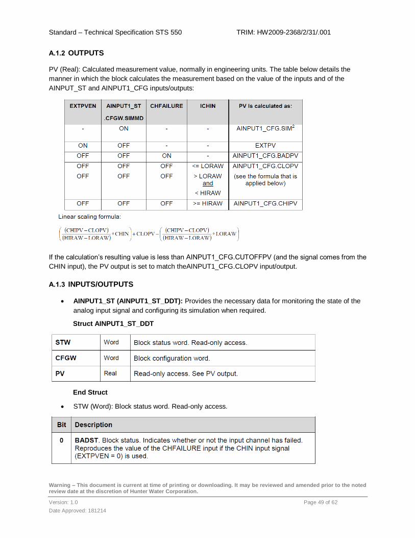
Standard – Technical Specification STS 550 TRIM: HW2009-2368/2/31/.001
Warning – This document is current at time of printing or downloading. It may be reviewed and amended prior to the noted review date at the discretion of Hunter Water Corporation.
Version: 1.0 Page 49 of 62
Date Approved: 181214
A.1.2 OUTPUTS
PV (Real): Calculated measurement value, normally in engineering units. The table below details the
manner in which the block calculates the measurement based on the value of the inputs and of the
AINPUT_ST and AINPUT1_CFG inputs/outputs:
If the calculation’s resulting value is less than AINPUT1_CFG.CUTOFFPV (and the signal comes from the
CHIN input), the PV output is set to match theAINPUT1_CFG.CLOPV input/output.
A.1.3 INPUTS/OUTPUTS
AINPUT1_ST (AINPUT1_ST_DDT): Provides the necessary data for monitoring the state of the
analog input signal and configuring its simulation when required.
Struct AINPUT1_ST_DDT
End Struct
STW (Word): Block status word. Read-only access.
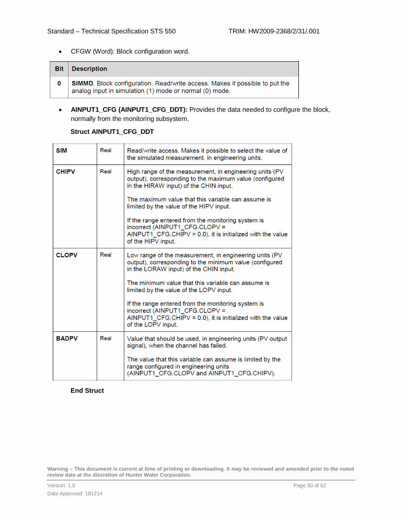
Standard – Technical Specification STS 550 TRIM: HW2009-2368/2/31/.001
Warning – This document is current at time of printing or downloading. It may be reviewed and amended prior to the noted review date at the discretion of Hunter Water Corporation.
Version: 1.0 Page 50 of 62
Date Approved: 181214
CFGW (Word): Block configuration word.
AINPUT1_CFG (AINPUT1_CFG_DDT): Provides the data needed to configure the block,
normally from the monitoring subsystem.
Struct AINPUT1_CFG_DDT
End Struct
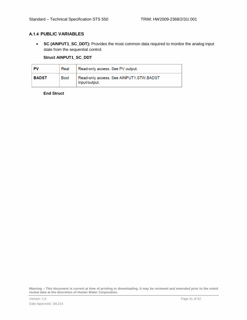
Standard – Technical Specification STS 550 TRIM: HW2009-2368/2/31/.001
Warning – This document is current at time of printing or downloading. It may be reviewed and amended prior to the noted review date at the discretion of Hunter Water Corporation.
Version: 1.0 Page 51 of 62
Date Approved: 181214
A.1.4 PUBLIC VARIABLES
SC (AINPUT1_SC_DDT): Provides the most common data required to monitor the analog input
state from the sequential control.
Struct AINPUT1_SC_DDT
End Struct

Standard – Technical Specification STS 550 TRIM: HW2009-2368/2/31/.001
Warning – This document is current at time of printing or downloading. It may be reviewed and amended prior to the noted review date at the discretion of Hunter Water Corporation.
Version: 1.0 Page 52 of 62
Date Approved: 181214
Appendix B. Sample PLC Code Layout
Function Block Layout – this applies to project specific code creation and functional project code
Header separates the code into functional sections Code neat and logically arranged
Comments to Left Comment Block
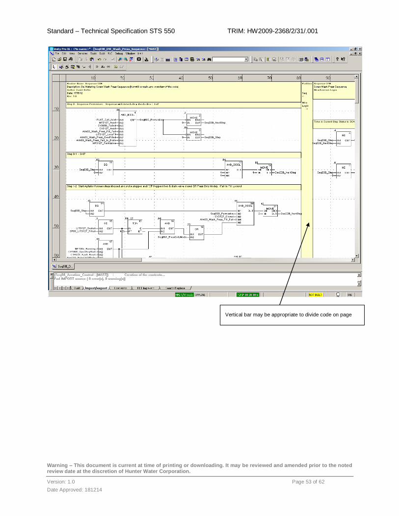
Standard – Technical Specification STS 550 TRIM: HW2009-2368/2/31/.001
Warning – This document is current at time of printing or downloading. It may be reviewed and amended prior to the noted review date at the discretion of Hunter Water Corporation.
Version: 1.0 Page 53 of 62
Date Approved: 181214
Vertical bar may be appropriate to divide code on page

Standard – Technical Specification STS 550 TRIM: HW2009-2368/2/31/.001
Warning – This document is current at time of printing or downloading. It may be reviewed and amended prior to the noted review date at the discretion of Hunter Water Corporation.
Version: 1.0 Page 54 of 62
Date Approved: 181214
Structure Text Layout
Comments, where appropriate, can be placed to the right of the code
System Bits Identified
Comments on each section
Comment Block

Standard – Technical Specification STS 550 TRIM: HW2009-2368/2/31/.001
Warning – This document is current at time of printing or downloading. It may be reviewed and amended prior to the noted review date at the discretion of Hunter Water Corporation.
Version: 1.0 Page 55 of 62
Date Approved: 181214
Appendix C. HMI Screen Configuration
C.1 HMI Configuration Screen
The HMI configuration panel is accessed by the 2 corner method. Pressing and holding on 2 corners will
bring up the display shown below. This page is used for setting up HMI project configuration and general
display attributes. Eg. IP address, screen brightness etc.
C.2 Hardware configuration
Hardware devices are configured using the general configuration screen. This includes the HMI
configuration, Project name, IP address etc.
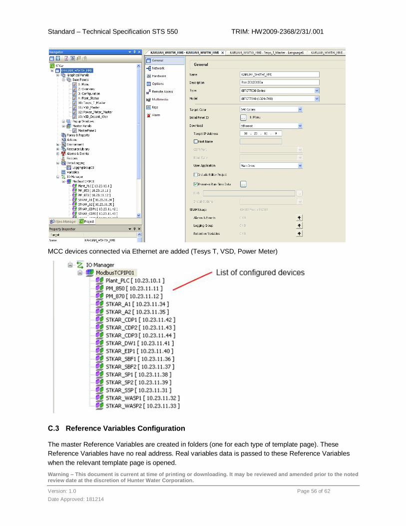
Standard – Technical Specification STS 550 TRIM: HW2009-2368/2/31/.001
Warning – This document is current at time of printing or downloading. It may be reviewed and amended prior to the noted review date at the discretion of Hunter Water Corporation.
Version: 1.0 Page 56 of 62
Date Approved: 181214
MCC devices connected via Ethernet are added (Tesys T, VSD, Power Meter)
C.3 Reference Variables Configuration
The master Reference Variables are created in folders (one for each type of template page). These
Reference Variables have no real address. Real variables data is passed to these Reference Variables
when the relevant template page is opened.

Standard – Technical Specification STS 550 TRIM: HW2009-2368/2/31/.001
Warning – This document is current at time of printing or downloading. It may be reviewed and amended prior to the noted review date at the discretion of Hunter Water Corporation.
Version: 1.0 Page 57 of 62
Date Approved: 181214
The Reference Variables include strings, digitals and analogs. They are internal variables to the HMI and
used on the Master Template pages.
Typical Reference Variable folders
Typical Reference Variables
Each Reference Variable is configured so that the relevant real Equipment Variable can be substituted
into the Reference Variable when the page is opened. The value of Parameter 1 replaces %s in the
reference string. Refer to Page open section for explanation of Parameter 1.
This resultant variable name equals the final real variable name. When the page is opened, the real
Equipment Variable will be displayed.
Eg. If Reference_Variable_Tesys.Name = SSP then
Tesys_SSP.AverageCurrent will be displayed.
C.3.1 Equipment Variables Configuration
Equipment variables are created in drive specific folders and with the same variable names as the
Reference Variables folder names. They are external variables with real address locations.

Standard – Technical Specification STS 550 TRIM: HW2009-2368/2/31/.001
Warning – This document is current at time of printing or downloading. It may be reviewed and amended prior to the noted review date at the discretion of Hunter Water Corporation.
Version: 1.0 Page 58 of 62
Date Approved: 181214
Typical Real Variables configuration
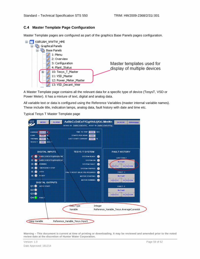
Standard – Technical Specification STS 550 TRIM: HW2009-2368/2/31/.001
Warning – This document is current at time of printing or downloading. It may be reviewed and amended prior to the noted review date at the discretion of Hunter Water Corporation.
Version: 1.0 Page 59 of 62
Date Approved: 181214
C.4 Master Template Page Configuration
Master Template pages are configured as part of the graphics Base Panels pages configuration.
A Master Template page contains all the relevant data for a specific type of device (TesysT, VSD or
Power Meter). It has a mixture of text, digital and analog data.
All variable text or data is configured using the Reference Variables (master internal variable names).
These include title, indication lamps, analog data, fault history with date and time etc.
Typical Tesys T Master Template page
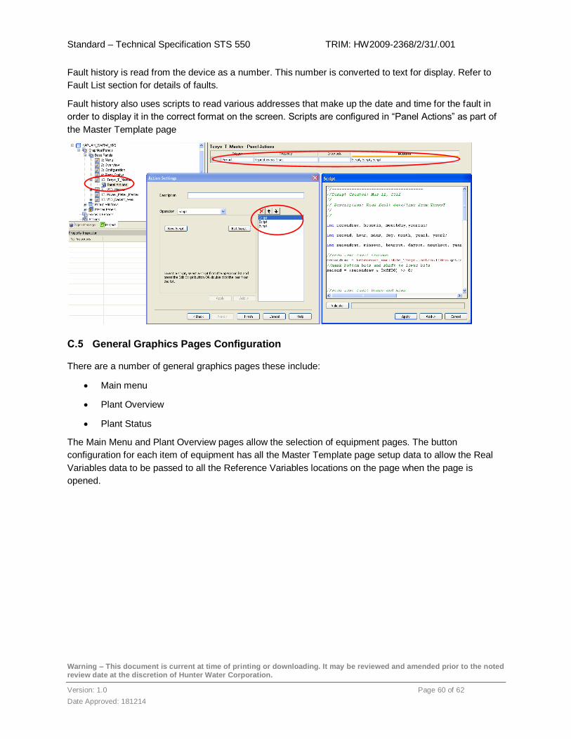
Standard – Technical Specification STS 550 TRIM: HW2009-2368/2/31/.001
Warning – This document is current at time of printing or downloading. It may be reviewed and amended prior to the noted review date at the discretion of Hunter Water Corporation.
Version: 1.0 Page 60 of 62
Date Approved: 181214
Fault history is read from the device as a number. This number is converted to text for display. Refer to
Fault List section for details of faults.
Fault history also uses scripts to read various addresses that make up the date and time for the fault in
order to display it in the correct format on the screen. Scripts are configured in “Panel Actions” as part of
the Master Template page
C.5 General Graphics Pages Configuration
There are a number of general graphics pages these include:
Main menu
Plant Overview
Plant Status
The Main Menu and Plant Overview pages allow the selection of equipment pages. The button
configuration for each item of equipment has all the Master Template page setup data to allow the Real
Variables data to be passed to all the Reference Variables locations on the page when the page is
opened.

Standard – Technical Specification STS 550 TRIM: HW2009-2368/2/31/.001
Warning – This document is current at time of printing or downloading. It may be reviewed and amended prior to the noted review date at the discretion of Hunter Water Corporation.
Version: 1.0 Page 61 of 62
Date Approved: 181214
Typical button configuration
Selecting the Spiral Sieve Screen button the switch settings page is displayed. On this page the “String
Set” function is used to load strings into Reference Variables. These Reference Variables are used to
pass values to the templates and to create the references to the specific hardware devices.
C.6 Alarms configuration
There are 2 types of alarms, System Fault alarms and configured alarms. System Faults are auto
generated by the HMI as inbuilt functions for hardware faults (eg. communications errors).
All configured alarms are setup up in the Real Variables configuration. There is only 1 alarm group
“AlarmGroup1”

Standard – Technical Specification STS 550 TRIM: HW2009-2368/2/31/.001
Warning – This document is current at time of printing or downloading. It may be reviewed and amended prior to the noted review date at the discretion of Hunter Water Corporation.
Version: 1.0 Page 62 of 62
Date Approved: 181214
Appendix D. Variable Descriptors Table
Descriptor Description
Auto Auto Device Operation
AVL Available
CB Circuit Breaker
CF Common Fault
CLK Clock
Close Command to close
Closed Closed position indication
DTY Duty Control Mode
ERR Error
ES Emergency Stop
FDB Feedback
FLT Fault
FS Flow Switch
FTSP Fail to Stop
FTST Fail to Start
FWD Forward
HHS High High Sensor
Hi High
HRS Hours
HS High Sensor
HTY Healthy status indication
HV High Voltage
ITL Interlock
JF Jog Forward
JR Jog Reverse
LIT Level Indicating Transmitter
LKS Leak Detection Sensor
LLS Low Low Sensor
Lo Low
Local Local Control
LS Limit Switch
LV Low Voltage
Man Manual Device Operation
MIN Minutes
Descriptor Description
OL Electrical Overload
Open Command to open
Opened Opened position indication
PB Pushbutton
PV Process Variable
RECL Recloser
Remote Remote Control
REV Reverse
RST Reset
Run Run command
Running Run Status Indication
SEC Seconds
SP Set point
SPD Speed
SID Speed Indication Transmitter
Start Start
Status Status
STB Standby Control Mode
Stop Stop Command
Stopped Stop Status
Test Test Device Operation
TX Transformer
Trip Trip
TRQ Torque
UL Under load
Volts Voltage