General Purpose SUT Adapter for TTCN-3 · test target, System Under Test (SUT), is tested. As of...
155
TAMPERE UNIVERSITY OF TECHNOLOGY Department of Information Technology ANTTI HYRKKÄNEN General Purpose SUT Adapter for TTCN-3 MASTER OF SCIENCE THESIS Subject approved by the Department Council on 09.06.2004 Examiners: Prof. Jarmo Harju (TUT) Sr. Researcher Mika Katara (TUT)
Transcript of General Purpose SUT Adapter for TTCN-3 · test target, System Under Test (SUT), is tested. As of...

TAMPERE UNIVERSITY OF TECHNOLOGY
Department of Information Technology
ANTTI HYRKKÄNEN
General Purpose SUT Adapter for TTCN-3
MASTER OF SCIENCE THESIS
Subject approved by the Department Council on
09.06.2004
Examiners: Prof. Jarmo Harju (TUT)
Sr. Researcher Mika Katara (TUT)

I
PREFACE
This Master of Science Thesis was done for Plenware Group and Nokia Networks during
the period Fall 2003 – Spring 2005. I would like to thank my supervisors and examiners
Jarmo Harju and Mika Katara for showing interest on this thesis work and for pointing
out errors in the text. Without the support of the following persons on TTCN-3 and tool
related matters this thesis work would not have been possible: Federico Engler, Stephan
Schulz, Stephan Tobies, Thomas Deiss, and Vesa-Matti Puro.
I would also like to thank Plenware Group and Nokia Networks for financing this work,
and the following companies for providing evaluation versions of their TTCN-3 tools:
OpenTTCN Oy, Telelogic Finland Oy, Testing Technologies IST GmbH, and Danet
Group.
I am very grateful to Tiina for showing extreme patience—most of the time.
Tampere, June 8th, 2005
Antti Hyrkkänen
Luhtaankatu 15 C 17
33560 Tampere
Finland

II
ABSTRACT
TAMPERE UNIVERSITY OF TECHNOLOGY
Department of Information Technology
Institute of Communications Engineering
HYRKKÄNEN, ANTTI: General Purpose SUT Adapter for TTCN-3
Master of Science Thesis, 102 pages, 45 enclosure pages.
Examiners: Prof. Jarmo Harju, Sr. Researcher Mika Katara
Financier: Plenware Group Oy, Nokia Networks
June 2005
Keywords: TTCN-3, Testing, System Under Test (SUT), Adaptation, SUT Adapter, Connection Management
TTCN-3 Core Language is a programming language designed for specifying Abstract Test Suites (ATS), which are collections of abstract test cases. These can be used for various kinds of testing (e.g. module, integration, conformance) of the test target, System Under Test (SUT). The communication between the test cases and the SUT is handled by an entity called SUT Adapter. The testing can be message-based and procedure-based, thus the SUT Adapter has to realize both kinds of communication with the SUT.
Because TTCN-3 Core Language is a rather new language (launched in 2000 by ETSI), the present amount of literature on it is very limited. The available literature consists of the TTCN-3 standard, and of overview articles and papers written by the people involved in the development of the language and TTCN-3 tools. The language itself is not very difficult to learn by examples to be able to write simple test cases. To be able to write an own SUT Adapter, one needs to have a deeper understanding what is possible to do with the language, how to use it and when, and how the execution of test cases is seen by the SUT Adapter. In practise, this means that one has to study well the different parts of the TTCN-3 standard.
One purpose of this thesis work is to give the reader an overview of the TTCN-3 Core Language, and what entities and standardized interfaces exist in a TTCN-3 test system. The presentation of these topics is based on different parts of the TTCN-3 standard, putting emphasis on the topics involved in SUT Adapter design. The presented information is then used as the basis for a new concept called Connection Manager System, which is specified in this thesis work. It is an adapter framework, which can be used to design such an adapter for TTCN-3 that provides several different kinds of message- and procedure-based communication means with the SUT. The different communication means can be controlled from the test cases in a uniform way, and new means can be later added without breaking the existing system. The specification of the Connection Manager System should give ideas to the reader what different things need to be considered in SUT Adapter design.
III
TIIVISTELMÄ
TAMPEREEN TEKNILLINEN YLIOPISTO
Tietotekniikan osasto
Tietoliikennetekniikka
HYRKKÄNEN, ANTTI: General Purpose SUT Adapter for TTCN-3
Diplomityö, 102 s., 45 liites.
Tarkastajat: prof. Jarmo Harju, vanh. tutkija Mika Katara
Rahoittaja: Plenware Group Oy, Nokia Networks
Kesäkuu 2005
Avainsanat: TTCN-3, Testaus, Testikohdejärjestelmä, Adaptaatio, Testikohdeadapteri, Yhteydenhallinta
TTCN-3 Core Language on ohjelmointikieli, joka on suunniteltu määrittelemään abstrakteja testisarjoja, jotka puolestaan koostuvat abstrakteista testitapauksista. Näiden avulla testikohdejärjestelmälle (System Under Test, SUT) voidaan tehdä esimerkiksi moduli-, integrointi- tai vastaavuustestausta. Testikohdejärjestelmän ja testitapausten välisen kommunikoinnin mahdollistaa ohjelma nimeltä testikohdeadapteri (SUT Adapter). Sen tulee pystyä toteuttamaan sekä sanomapohjaista että proseduuripohjaista viestintää testikohteen kanssa, koska kommunikointi voi perustua molempiin näistä.
Koska TTCN-3 Core Language on melko uusi ohjelmointikieli (ETSI:n vuonna 2000 julkaisema), siitä on hyvin vähän kirjallisuutta saatavilla. Olemassa oleva kirjallisuus koostuu lähinnä TTCN-3-standardista ja kielen sekä siihen liittyvien työkalujen kehittämiseen osallistuneiden ihmisten kirjoittamista artikkeleista ja käyttöohjeista. Yksinkertaisia testitapauksia on kuitenkin mahdollista oppia kirjoittamaan esimerkkien avulla, koska kieli itsessään ei ole kovin vaikea. Testikohdeadapterin suunnittelu ja toteutus sen sijaan vaatii kielen ominaisuuksien syvällisempää tuntemusta: miten kieltä kannattaa käyttää eri tilanteissa ja miten testikohdeadapteri näkee testitapausten suorituksen.
Tämän diplomityön yhtenä tarkoituksena on antaa lukijalle yleiskuva TTCN-3-kielestä sekä TTCN-3-testijärjestelmään liittyvistä komponenteista ja niiden välisistä rajapinnoista. Näiden asioiden esitys perustuu TTCN-3-standardin eri osiin ja se keskittyy testikohdeadapterin kannalta oleellisiin tekijöihin. Tämän taustatiedon pohjalta työssä esitetään uusi käsite yhteydenhallintajärjestelmä (Connection Manager System). Yhteydenhallintajärjestelmän tarkoituksena on tarjota runko testikohdeadapterille, joka tarjoaa useita erilaisia sanoma- ja proseduuripohjaisia kommunikointikeinoja käytettäväksi testikohdejärjestelmän kanssa. Näitä erilaisia kommunikointikeinoja hallitaan testitapauksista yhtenäisellä tavalla ja niitä voidaan lisätä myöhemmin adapteriin muuttamatta jo olemassa olevaa toteutusta. Diplomityössä kuvatun yhteydenhallinta-järjestelmän määrittelyn perusteella lukijalle tulisi muodostua kuva siitä, mitä asioita tulee ottaa huomioon testikohdeadapterin suunnittelussa.

IV
TABLE OF CONTENTS
PREFACE............................................................................................................ I ABSTRACT......................................................................................................... II TIIVISTELMÄ..................................................................................................... III TABLE OF CONTENTS.....................................................................................IV ABBREVIATIONS..............................................................................................VI DEFINITIONS OF TERMS ...............................................................................VII
1 INTRODUCTION ........................................................................................... 1
2 TTCN-3 CORE LANGUAGE.......................................................................... 3
2.1 TTCN-3 as a Programming Language ........................................................3
2.2 Module........................................................................................................4
2.3 A Test Case and Testcase..........................................................................5
2.4 Components, Ports, and Test Configurations..............................................6
2.5 Verdict ........................................................................................................9
2.6 Testcases, Functions, and Altsteps...........................................................10
2.7 Types and Values .....................................................................................11
2.8 Templates.................................................................................................13
2.9 Communication Operations.......................................................................15
2.10 Alternative Behaviour ................................................................................17
2.11 Timers.......................................................................................................20
2.12 Encoding and Decoding ............................................................................20
3 TTCN-3 RUNTIME INTERFACE ................................................................. 23
3.1 Structure of TTCN-3 Test System .............................................................23
3.2 Overview of TTCN-3 Runtime Interface ....................................................26
3.3 Connection Handling.................................................................................28
3.4 Message-based Communication...............................................................29
3.5 Procedure-based Communication.............................................................30
4 GENERAL PURPOSE SA ........................................................................... 33
4.1 Motivation and Background.......................................................................33
4.2 Connection Manager System Concept......................................................35
4.3 Requirements ...........................................................................................40 4.3.1 Connections........................................................................................... 41 4.3.2 Identifiers ............................................................................................... 44 4.3.3 Information storage................................................................................ 46 4.3.4 Concurrency .......................................................................................... 50 4.3.5 Operation handling order....................................................................... 51

V
5 INTERFACES.............................................................................................. 56
5.1 Notation ....................................................................................................56
5.2 Connection Interface.................................................................................57 5.2.1 On design choices ................................................................................. 57 5.2.2 Type definitions ..................................................................................... 60 5.2.3 On transfer syntax and encoding .......................................................... 68 5.2.4 Operations ............................................................................................. 73
5.3 Error Handling...........................................................................................78
5.4 Connection Interface Usage Examples .....................................................81 5.4.1 Operation messages ............................................................................. 82 5.4.2 TCP connection – open request............................................................ 83 5.4.3 TCP connection – opened confirmation ................................................ 85 5.4.4 TCP connection – data .......................................................................... 88 5.4.5 TCP connection – close request ........................................................... 89 5.4.6 TCP connection – closed confirmation and indication .......................... 90 5.4.7 TCP server example.............................................................................. 91
5.5 Overview of CM System Interface.............................................................95
5.6 Overview of CM Class Interface................................................................97
5.7 Overview of Mapping Interface..................................................................97
6 CONCLUSIONS .......................................................................................... 99
REFERENCES ............................................................................................... 102
APPENDICES................................................................................................. 103
A INTERFACES IN DETAIL.......................................................................... 103
A.1 CM System Interface ..............................................................................103 A.1.1 Data types........................................................................................... 104 A.1.2 Operations .......................................................................................... 107
A.2 CM Class Interface .................................................................................125 A.2.1 Data types........................................................................................... 126 A.2.2 Operations .......................................................................................... 126
A.3 Mapping Interface ...................................................................................136 A.3.1 Data types........................................................................................... 137 A.3.2 Operations .......................................................................................... 137
B MSC DIAGRAMS....................................................................................... 140
B.1 Open.......................................................................................................140
B.2 Control ....................................................................................................141
B.3 Status .....................................................................................................142
B.4 Close ......................................................................................................143
B.5 Closed ....................................................................................................144
B.6 Terminate................................................................................................145
B.7 Message .................................................................................................146
B.8 Procedure ...............................................................................................146
B.9 Receipt of a message or procedure operation.........................................147

VI
ABBREVIATIONS
CCI CM Class Interface. The interface between the CM System Component and the CM Classes.
CD Coding/Decoding
CI Connection Interface. The TTCN-3 language level user interface to the CM System.
CM Connection Manager
CSI CM System Interface. The interface provided by the CM System Component to the SA.
ETS Executable Test Suite (defined in ISO/IEC 9646-1)
IDL (CORBA) Interface Definition Language
IUT Implementation Under Test
MI Mapping Interface. The interface between the SA and the CMs.
MSC Message Sequence Chart
MTC Main Test Component
PA Platform Adapter
PDU Protocol Data Unit
PTC Parallel Test Component
SA SUT Adapter
SAP Service Access Point
SUT System Under Test
T3RTS TTCN-3 Runtime System
TCI TTCN-3 Control Interface
TL Test Logging
TM Test Management
TMC Test Management and Control
TRI TTCN-3 Runtime Interface
TSI Test System Interface
TTCN-2 Tree and Tabular Combined Notation, 2nd Edition
TTCN-3 Testing and Test Control Notation, version 3

VII
DEFINITIONS OF TERMS
CM Class Entity that provides communication means of certain kind with the SUT. Each established connection using a class is handled by a CM belonging to the class.
CM System A general term meaning the CM System Component, the CM Classes, and the CMs, along with their data structures.
CM System Component Entity that provides the CM System Interface to the SA. It uses the services provided by the CM Classes that are registered into it.
cmClassReg Data structure within the CM System Component, which contains interfaces to all the CM Classes that are present in the CM System.
Codec Piece of software that encodes values of abstract TTCN-3 types into transfer syntax form and back.
Connection Manager (CM) Entity that maintains an opened data connection, and which can be controlled via a control connection.
Control connection A connection that is used to control one or more data connection of a component.
Control port A port that is used for configuring connections for data ports.
controlMap Data structure within the CM System Component, which is used by it to find which data connections are controlled by which control connections.
Data connection A connection that a component has opened with Connection Interface Open operation.
Data port A port via which a test case component can communicate with the SUT.
(En)coding attributes Both the encode and variant attributes, that can be defined for a TTCN-3 language element with the with statement. These are used to select which codecs are used and to guide the codecs in encoding of abstract TTCN-3 values into transfer syntax form.
handlerMap Data structure within the CM System Component, which is used by it to find which CM Class and which particular CM is handling a certain connection.
Stand-alone control connection
A connection that is not used to control any data connection, but which is used as a signaling link with a CM.
tsiMap Data structure within the SA, which is used for storing component and port identifiers of connections. Defined in Section 4.3.3.
TTCN-3 tool A program that either compiles or interprets modules written in TTCN-3 Code Language to make them executable.

1
1 INTRODUCTION TTCN-3 is a language designed for specifying Abstract Test Suites (ATS), with which the
test target, System Under Test (SUT), is tested. As of writing this document, there is very
little literature on TTCN-3 as a test programming language, and even less, if anything at
all, on SUT Adapter (System Under Test Adapter, SA) implementation. The reason for
this is that TTCN-3 is a new language that was published by European
Telecommunications Standards Institute (ETSI) in 2000 and its standard is still evolving.
A SUT Adapter is piece of software that handles the actual communication between the
SUT and the program that runs test cases and decides their results. When one wants to
build an own adapter from the scratch, the material one can resort to is the TTCN-3
standard, and what happens to come with the used TTCN-3 tool. A TTCN-3 tool is a
program that is required to interpret or compile the written test suites (ATS) to make them
executable. There are no examples in the standard on how one could realize an adapter,
and what things should be considered. The standard does provide an interface via which
the adapter communicates with the rest of test system, but how one utilizes the interface
operations and their parameters is left to the adapter designer. What comes to the
documentation and example adapters that currently come with the TTCN-3 tools, these
seem to be very minimal as of writing this document. The documentation might only state
that "The TRI interface is specified in [T3TRI]. If you need an adapter using TRI
interface for a special purpose, please contact our sales department.", which is not very
helpful. The example adapter, if such is provided, can be a simple adapter that opens a
TCP or UDP connection with a fixed end-point, without much configuration possibilities.
It can also be, that this adapter can be used with the message-based operations TTCN-3
language provides, but the procedure-based testing functionality of TTCN-3 cannot be
utilised. In addition, this kind of adapter may lack any kind of error handling and it may
not be suitable for situations in which test case configuration can change during an on
going test case.
The purpose of this thesis work is to give the reader a short overview on TTCN-3
language and test system, and how one can build such an adapter that can be used for
establishing communication channels between test targets of different kinds. The

2
presented adapter system alone cannot be used for communication with the test targets,
but it provides a framework into which real adapter implementations can be added, and
which can be controlled in a uniform way. This adapter framework or system is called as
Connection Manager System in this document. The text should give ideas to the reader
what things should and could be considered in adapter design, even if the presented
framework is not used.
The content of this document is divided into theory and background part (Chapters 2 and
3), which gives to the reader an overview of the TTCN-3 based on its standards, and to
practical part (Chapters 4, 5, and Appendix A), which specifies a Connection Manager
System that is compatible with the TTCN-3 standards.
Chapter 2, “TTCN-3 Core Language”, gives an overview of TTCN-3 Core Language,
which is used for specifying test cases. It contains TTCN-3 code fragments to show what
the language looks like, and it contains references to the sections of the standards where
the presented features of the language are specified in more detail. Chapter 3, “TTCN-3
Runtime Interface”, describes what different elements and standardized interfaces are
present in a TTCN-3 test system, and how they are related to the test cases written in the
core language. After this, the interface between executable test cases and the adapter that
communicates with the test target is explained in more detail.
The concept of the Connection Manager System is explained in Chapter 4, “General
Purpose SA”, which describes the entities present in the system and interfaces between
them. The chapter also specifies requirements to the system: how connections and entities
are identified within the system, what information is stored and where, and how
operations are handled concurrently. The interfaces between the entities are specified in
Chapter 5, “Interfaces” and in Appendix A. This is done at an abstract level, meaning that
the information that is passed between the elements, and the operations for doing this, are
specified in a language independent manner. Message Sequence Charts showing the use
of the interfaces can be found in Appendix B. Chapter 6 contains a summary and
conclusions of the presented ideas.

3
2 TTCN-3 CORE LANGUAGE The TTCN-3 standard is divided into six parts, which each cover a different part of the
language: Part 1: TTCN-3 Core Language [T3CORE], Part 2: TTCN-3 Tabular
Presentation Format (TFT) [T3TFT], Part 3: TTCN-3 Graphical Presentation Format
(GFT) [T3GFT], Part 4: TTCN-3 Operational Semantics [T3OS], Part 5: TTCN-3
Runtime Interface (TRI) [T3TRI], and Part 6: TTCN-3 Control Interface (TCI) [T3TCI].
Of these, the Part 1: TTCN-3 Core Language is the most essential. It specifies the textual
syntax of the TTCN-3 language and how one writes test cases with it. It also serves as the
syntactical and semantic basis for other non-textual representation formats of the
language, such as the tabular format and graphical format, which are specified in Part 2
and Part 3 of the standard. In Part 4: TTCN-3 Operational Semantics, the semantics of the
core language is specified in detail by using a flow graph notation. It shows how the
statements in a TTCN-3 module (a compilation unit in TTCN-3, such as a .c file in C) are
to be interpreted when the test cases are executed.
This chapter provides an overview of the TTCN-3 core language based on ETSI standard
ETSI ES 201 873-1 V2.2.1 (2003-02) "Methods for Testing and Specification (MTS);
The Testing and Test Control Notation version 3; Part 1: TTCN-3 Core Language"
(referenced as T3CORE in the text). Topics of the language relevant to this thesis work
are shown in greater detail, while less relevant are only mentioned or completely omitted,
irrespective of their importance in the TTCN-3 core language. The text contains
references to the sections of [T3CORE] where more detailed information on the presented
topics can be found. Where relevant, the text uses the courier font to highlight the
reserved words of the language.
2.1 TTCN-3 as a Programming Language
TTCN-3 Core Language can be seen as a programming language, which is meant for
specifying collections of test cases, Abstract Test Suites (ATS). To be able to execute the
test cases within an ATS, a tool (compiler, interpreter) is required to transform the ATS
into an Executable Test Suite (ETS). The language is independent of the environment in
4
which the testing is done, what is being tested, and what kind of testing is in question.
The testing can be module testing, integration testing, conformance testing, and so on
[T3CORE: s. 4]. The test target can be a function library written in some language X, a
web server, or a network of components whose joint behavior is tested via some chosen
interfaces.
The language does not currently provide syntax for real-time testing; events that occur
have no time stamps, and it is not possible to read absolute time, i.e. system time. Hence,
one cannot directly test whether something happens at a given time of day, or whether
events occur within certain tolerance, without building this functionality by writing
custom (external) functions [T3CORE: s. 16.1.0], and by possibly time-stamping events
(function calls, messages) outside the TTCN-3 Core Language. In [TIMED] a solution is
proposed to extend TTCN-3 to handle real-time requirements.
The difference between TTCN-3 and other programming language is that it has been
designed for testing. It provides at language level means for handling test verdicts,
operations for procedure- and message-based communication, and extensive abilities to
specify and match against data.
2.2 Module
The TTCN-3 language element called module corresponds to a compilation unit in
traditional programming languages [T3CORE: ch. 7]. It can be analyzed, compiled or
interpreted, it may contain a single or several test cases, and it can be used as a library by
other modules. The TTCN-3 standard does not mention the relationship between modules
and how they are stored into files. Because of this, some TTCN-3 tools allow one to have
several modules defined within a file, and some tools only understand one module per
file. This may cause problems when the used tool is changed. A smaller problem is that
the used file suffix also varies between tools.
Each module is divided into two parts, definitions part and control part, both of which
are optional. The definitions part contains top-level definitions, such as type definitions,
data (template) and constant definitions, port and component definitions, and function and
testcase definitions. It is possible to import definitions from other modules to make

5
them visible in the referring module. The control part can be seen as the "main function"
of the module and its purpose is to call the test cases defined in the definitions part. It
contains the logic for executing the test cases in certain order, it can apply execution time
restrictions to the test cases, and it can use the definitions specified in the definitions part
of the module to specify local variables. Because the control part is optional, the used
TTCN-3 tool may provide an alternative way to execute test cases without using the
control part. For example, it can have a graphical user interface from which the executed
test cases can be selected.
It is possible to specify parameters for a module, meaning that when a test case or the
control part of the module is executed, it can read these parameters and behave according
to them. The parameters are like module global constants, whose values are set at the start
of the execution. For example, one could have the address of the test target and maximum
execution time as module parameters.
The following TTCN-3 code fragment shows a module definition of module MyModule ,
which could be stored in file MyModule.ttcn :
module MyModule { // Definitions part import from OtherModule all; type integer MyPosInt (0 .. infinity); testcase tc_myFirstCase() runs on MyComponent sy stem MyTsi { ... } // Control part control { execute(tc_myFirstCase(), 10.0); //Maximum ex ecution time 10.0 seconds execute(tc_mySecondCase()); //No maximum execution time } }
2.3 A Test Case and Testcase
TTCN-3 Core Language has a language element called testcase [T3CORE: ch. 17].
The difference between testcase and a “test case” is that testcase is language
element, while test case is a general term used in this document to mean a set of checks
done to the System Under Test (SUT), in order to test some specific behavior. A test case

6
consists of a testcase , that can be seen as the main function of a single case, and of
any other functionality executed in parallel with the testcase . A testcase is always
executed within an entity called component , and it can call normal function s and
altstep s to extend its behavior. The result of executing a testcase is a verdict,
which tells whether the system under test passed the test.
A test case can be both message- and procedure-based [T3CORE: ch .23]. Message-based
testing consists of sending messages to the System Under Test (SUT), receiving messages
from it, checking whether messages were not received in time, and of checking whether
the received messages are in the right order and that they contain right values. Procedure-
based testing consists of calling functions of the SUT, receiving return values and
exceptions, receiving function calls, and of passing function return values and raised
exceptions to the SUT.
2.4 Components, Ports, and Test Configurations
The behavior of a single test case consists of executing functionality (testcases and
functions) in one or more components. A component is a user specified entity, which
contains user-defined port s, via which the component can interact with other
components and the SUT with message and procedure operations [T3CORE: s. 8]. In
addition to the ports, the component may contain private variables and timers. The
component itself does not specify any kind of behavior but it provides an environment for
it. This means that one can start functionality in the component and this functionality can
then use the ports, variables, and timers of the component. The functionality that can be
started in the component can be either a testcase or a function [T3CORE: s. 22.5.
A component is shown conceptually in Figure 2-1.
ComponentPort
PortVariableVariable
Timer
ComponentPort
Behaviour:testcase or
function
ComponentPort
Message and/or procedure based communication
Figure 2-1: Component model.

7
One of the components that exist during a test case is called Main Test Component
(MTC). It is special in the sense that when a test case is chosen to be executed, this MTC
component is automatically created to execute it. When the MTC reaches the end of its
execution, then the test case ends. The MTC is responsible for creating other components,
which are called Parallel Test Components (PTC), and for starting functionality in them.
The creation of new PTCs and starting of functionality in them can also be done by the
PTCs.
Another special component that exists for the duration of the test case is called Test
System Interface (TSI) component (or just system component or system for short)
[T3CORE: s. 8.3]. Unlike the other components, one cannot start any functionality in it,
and it does not have any internal variables or timers. This component acts as an abstract
interface between the test case and the System Under Test (SUT). The ports of the system
component (TSI) are visible to the SUT Adapter, which routes any messages or procedure
operations seen at these ports between the test case components and the real test system
interface at the SUT (see Figure 2-2).
The components and TSI are abstract TTCN-3 Core Language level constructs. The
actual program that implements the components and test case logic is called TTCN-3
Executable (TE). It interacts with the SUT Adapter via TTCN-3 Runtime Interface (TRI).
The TE, SUT Adapter and TRI are not part of the TTCN-3 Core Language, so they are
explained later in Chapter 3.
When two components want to communicate with each other, the ports of the components
have to be first connected with each other. When a component needs to communicate
with the SUT, its port has to be mapped with one of the ports of the TSI component
Real Test System Interface
TTCN-3 Executable (TE)
TSI Component
Port
Port Port
Port Component
Port
SUT Adapter (SA)
SUT
Access point
Access point
Abstract Test System Interface
TRI
Mapping and propagation of messages
and procedure operations
Figure 2-2: Test System Interface.

8
(when a port of a component is connected with a port of the TSI component, it is said that
they are mapped with each other, instead of connected with each other). After this, the
component can perform message-based, procedure-based, or both kinds of
communication operations via the port. What messages and procedure calls can be
performed via the port depends on the type definition of the port. A type definition of the
port specifies whether the port can be used for message-based or procedure-based
communication, or for both, and it contains a list of supported message types and
procedures signatures. The list also specifies the direction in which each item can move
through the port, as seen by the component in which the port is used [T3CORE: s. 8.4.0].
This direction information restricts what kind ports can be connected and mapped with
each other: a port has to be able to receive what a connected port may send. The precise
rules for legal port connections and mappings can be found in [T3CORE: s. 22.2.1].
When the component sends a message or performs a procedure call via its port that is
connected with a port of another component, the message is delivered to the recipient’s
port queue, which is modeled as an infinite length FIFO queue in TTCN-3 [T3CORE: s.
8.1]. In the case the port of the sending component is mapped with a system component
port, the message is delivered to the SUT by some means by the SUT Adapter (SA). It
depends on the implementation of the SA how it knows to deliver the messages to the
right place. The SA is further explained in Chapter 3.
The components are created, their execution is started and stopped, and their port
mappings are done with the configuration operations specified in [T3CORE: ch. 22]. The
following TTCN-3 code fragment shows how the component executing the shown
function creates a new PTC, connects one of its own ports with a port of the PTC, maps
one other port of the PTC with a system port, starts behavior in the PTC, and waits until
the PTC stops its execution, after which it explicitly stops itself:

9
function f_startup() runs on MyComp { /* A new component of type SomeComp is created, and a reference to this * component is stored into variable cp_someComp Ref. */ var SomeComp cp_someCompRef := SomeComp.create; /* Local port pt_control is connected with the p ort pt_ctrl * of the newly created component. */ connect(self:pt_control, cp_someCompRef:pt_ctrl) ; /* Port pt_data of the newly created component i s mapped * with the port tcp of the test system interfac e component. */ map(cp_someCompRef:pt_data, system:pt_tcp); /* Function tp_someBehaviour() is started in the component, * and string "10.10.10.1" is given to it as a p arameter. * .start() is a non blocking command, so the ex ecution continues * immediately after the below statement. */ cp_someCompRef.start(tp_someBehaviour("10.10.10. 1")); // Wait for cp_someCompRef to finish its executi on. cp_someCompRef.done; // Set own verdict to pass. setverdict(pass); // Stop own execution. self.stop; }
2.5 Verdict
Every component that exists during a test case has a local object called verdict, which it
can set (setverdict ) based on how it experiences the behavior of the other
components and the SUT [T3CORE: ch. 25]. Components can also read their own current
verdict value (getverdict ). The possible verdict values a component can set are
none , pass , inconc , and fail . Once a component has set a value for its verdict, it
can only "worsen" the verdict value. What this means is that none can be seen as the best
verdict value and fail as the worst, and the verdict value changes only when a value
worse than its current value is tried to be set. Thus, one could set none verdict to pass ,
and pass to fail , but not fail back to pass or none . The inconc verdict stands
for inconclusive, and it can be used for example in situations, in which the SUT does not
do anything illegal, but an unexpected situation occurs which the test case has not been
designed to handle.
The total verdict of the test case is the worst verdict of the components that participated in
the test, and its value is resolved by the used TTCN-3 tool.

10
For example, when the testing consists of transferring data with the SUT concurrently in
two different directions, uplink and downlink, there could exist an own PTC component
for handling and verifying the data transfer in each direction. The total verdict of the test
case depends now on the verdicts of the uplink and downlink transfer, which can be seen
as sub-tests of the whole test case. These sub-tests could exist in some other test cases as
stand-alone test cases (uplink data transfer test, downlink data transfer test), or as parts of
more complex test cases.
2.6 Testcases, Functions, and Altsteps
TTCN-3 has three different function-like language elements: testcase , function ,
and altstep [T3CORE: chs 16, 17]. Common to these is that they can define local
variables and timers.
A testcase is a function whose execution is always started in a component, and its
return value is always the total verdict of the test case. The definition of the testcase
contains information on in which kind of component it can be started (runs on ), and
what kind of test system interface is used during the test case (system ). The execution
of the testcase can be started in the control of part of the module, or directly by the
used TTCN-3 tool when the control part is not used. In addition to any local definitions,
the testcase can use the component internal definitions such as ports and variables.
A normal function can have input parameters, output parameters, input-output
parameters, and it can return a value. It is also possible to specify that the function can
only be called or started within a component of a certain type, which makes the internal
definitions of the component visible to the function (ports, timers, and variables).
TTCN-3 has also external functions , which can be called from the test cases, but
their implementation is outside the TTCN-3. An external function call results in a
TRI operation, which instructs the used Platform Adapter (PA) to call the specified
function (PA will be explained in Chapter 3).
Altstep is used for specifying action whose execution is triggered by some "receiving"
event or operation, such as a timeout or receipt of a message. Like with testcase and

11
function , it can be given access to the internal definitions of the component. An
example of an altstep is given in Section 2.10 Alternative Behaviour.
The below TTCN-3 fragment defines a component type, and a testcase that be executed
on an instance of the component type:
// Component type definition type component MyComp { // Component local definitions: // Variable var charstring g_identifier; // Port of type MyPort port MyPort pt_port; } /* Testcase definition. This testcase gets executed in Main Test Component * of type MyComp, and the used Test System Interfa ce component is of * type MyTsiComp. */ testcase tc_myCase(in charstring p_id) runs on MyComp system MyTsiComp { g_identifier := p_id; pt_port.send(g_identifier); ... }
2.7 Types and Values
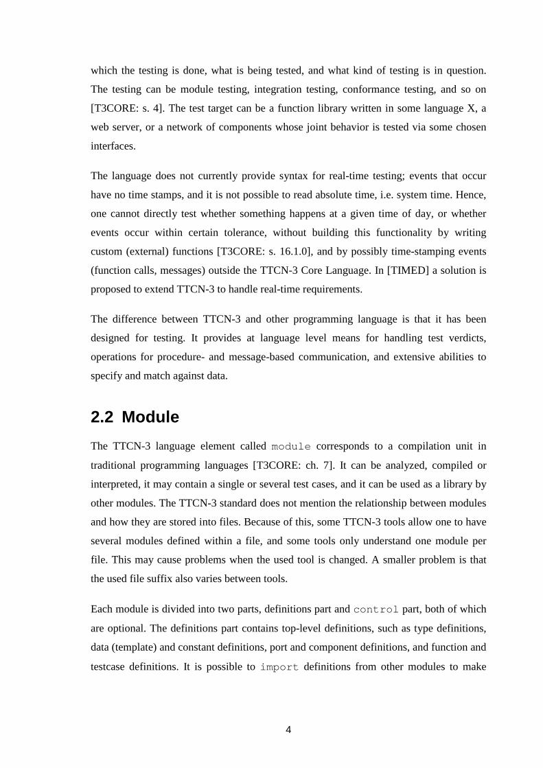
TTCN-3 provides a set of basic and structured types, from which the user can derive own
sub-types by restricting their values [T3CORE: s.6]. All these root types are listed in
Table 2-1. The word "range" in the sub-type column means, that the user can define an
own subtype of the root type by specifying a range of valid values to it, the word "list"
means that the user can specify a list of valid values for the type, and "length" means a
length restriction for a type that can be indexed. There are no default restrictions on the
root types, so a value of type integer or float can hold any value from -infinity to
infinity, and a string have a length from zero to infinity. In practice, the maximum values
depend on the used TTCN-3 tool.
Special to TTCN-3, it is possible to define a field of structured type record to be
optional, meaning that its value can be omitted, and it can be checked whether the field
value has been set [T3CORE: ss. 6.3.1, C.15]. The union type of TTCN-3 is different
from the union type of C-language. It contains only the alternative or variant that has been
assigned to it; the alternatives are not different representation formats of the data stored
12
into the union. It is possible to ask from a value of union type if a specified variant is
stored into it, by using the predefined ischosen function [T3CORE: ss. 6.3.5, C.16].
TTCN-3 is not strongly typed language [T3CORE: s. 3.1], but it does require type
compatibility as specified in [T3CORE: s. 6.7]. Strong typing is required in the case of
enumerated type, and in the communication operations that are explained in Section
2.9. In the case of non-structured types the type compatibility is defined as:
“value "b" (of type B) is compatible to type "A"if type "B" resolves to the same root type as type "A" (i.e. integer) and it does no t violate subtyping (e.g. ranges, length restrictions) of type "A".” [T3CORE: s.6.7.1 ]
This mean that one can assign a value of type A to a value of type B, when the allowed
values of A is a subset of the allowed values of B.
There is no automatic type conversion or promotion like in C in TTCN-3, so it is not
possible to mix for example integers and floats in the same expression. TTCN-3 does
provide a set of predefined functions with which it is possible to convert a type of a
certain kind to another kind. There is also no "free" type in TTCN-3, that could be used
for containing a value of any kind. However, there exists a type called anytype that can
Table 2-1: Overview of TTCN-3 Types [T3CORE: s. 6.0, Table 3].
Class of type Keyword Sub-type integer range, list char range, list universal char range, list float range, list boolean list objid list
Simple basic types
verdicttype list bitstring list, length hexstring list, length octetstring list, length charstring range, list, length
Basic string types
universal charstring range, list, length record list record of list, length set list set of list, length enumerated list
Structured types
union list Special data types anytype list
address port
Special configuration types
component Special default types default

13
be used for storing value of any other type, that is defined in the same module in which
the value of anytype is defined. In other words, the anytype is defined "as a
shorthand for the union of all known types in a TTCN-3 module" [T3CORE: s. 6.4].
When a component performs a communication operation via its port that is mapped with
a TSI port, it is possible, but not required, to use special address type to address a
specific SUT or an entity within the SUT [T3CORE: s. 8.6]. This address type is specified
separately in each module, and it can be set as one of the user specified types, or it can be
left as open type. In the case it is left as open type, and when a message or procedure
operation is received from the SUT, one can use it to store the address value of the SUT
without understanding its contents. The stored address value can then be used when
communicating back to the same SUT entity. The SUT Adapter can use the address value
(when present) to deliver information between the correct test case component and SUT
entity.
2.8 Templates
A template is data structure, that can be "used to either transmit a set of distinct values
or to test whether a set of received values matches the template specification" [T3CORE:
s. 14.0].
A template specifies a single value when it is used for generating data to be transmitted,
and it can be optionally parameterized. A parameterized template can contain an
expression whose value specifies the value of the template. When the template specifies a
value for a structured type, some of the fields of the value can contain fixed values and
some are set at run time with the parameters. This is very useful for defining differently
parameterized templates of the same type for different situations. For example, when a
message corresponding to a protocol data unit (PDU) of protocol X needs to be
transmitted, it is feasible that the test case writer needs only to specify values for the
fields of interest, and default values are used for the other fields. For example, one
parameterized field could be message sequence number, which needs to be increment
after each sent PDU. The below TTCN-3 fragment shows a definition for the PDU type
and a parameterized template for it:

14
// Type definition of type MyPdu. type record MyPdu { integer seqNum, charstring data } // Parameterized template of type MyPdu with identi fier a_myPdu_s. template MyPdu a_myPdu_s(integer p_seqNum) := { seqNum := p_seqNum, data := "Who are you?" }
When a template is used in the receiving direction to match with received values, each
template can specify a set of values that it matches with. The template definition below
matches any value, which is of type MyPdu, has seqNum within range 100 to 200, and
contains as data either the character string "Alice" or "Bob":
// Matching template. This cannot be sent, only com pared against received data. template MyPdu a_myPdu_r := { seqNum := (100 .. 200), data := ("Alice", "Bob") }
In TTCN-3 it is possible to construct a new template from already specified templates, by
using them as (field) values within the new template, either by directly assigning them or
by passing them as parameters to the new template. A new template can also be defined
by modifying a template by redefining it partially. These features make the creation of
very complex values easy, but it is also very easy to specify complex hard-to-maintain
dependencies between templates. A change in one template might change the matching of
several other templates, thus care must be taken and planning used when specifying large
sets of test data. The below example shows the use of existing templates to specify new
ones:
template charstring a_allowedData := ("Alice", "B ob"); template integer a_validRange := (100 .. 200) ; // a_validRange can be passed to a_myPdu2_r as a pa rameter template MyPdu a_myPdu2_r(template integer p_ a_seqNum) := { seqNum := p_a_seqNum, data := a_allowedData } // Modified template, uses a_myPdu2_r as basis. template MyPdu a_myPdu3_r(template integer p_ a_seqNum) modifies a_myPdu2_r := { data := "Eve" }

15
In addition to be able to specify a list or a range of values, TTCN-3 provides other
matching mechanisms, such as matching against a string pattern (similar to a regular
expression), string of specific length, complement of a list, omitted value, any value, and
any-or-omitted value. The matching mechanisms are introduced in [T3CORE: s. 14.3]
and their usage is specified in Annex B of the same document.
The examples given in this section concerned only type templates. Of equal importance,
TTCN-3 also provides syntax for specifying templates for function calls. These templates
can be used to specify which SUT function should be called with what parameter values,
and what calls are expected from the SUT.
2.9 Communication Operations
TTCN-3 has both message- and procedure-based communication operations with which
components can interact with each other and with the SUT. All the communication
operations are listed in Table 2-2.
The operations send , call , reply , and raise are called sending operations, and they
use syntax similar to each other. Of these, send , reply , and raise operations are
automatically non-blocking, meaning that execution continues after the operation call
without waiting for the recipient to actually receive and handle the message or procedure
Table 2-2: Overview of TTCN-3 communication operations [T3CORE: s. 23.10, Table 17].
Communication operations Communication operation Keyword Can be used at
message-based ports
Can be used at procedure-based
ports Message-based communication Send message send Yes Receive message receive Yes Trigger on message trigger Yes Procedure-based communication Invoke procedure call call Yes Accept procedure call from remote entity getcall Yes Reply to procedure call from remote entity reply Yes Raise exception (to an accepted call) raise Yes Handle response from a previous call getreply Yes Catch exception (from called entity) catch Yes Examine top element of incoming port queues Check msg/call/exception/reply received check Yes Yes Controlling operations Clear port clear Yes Yes Clear and give access to port start Yes Yes Stop access (receiving & sending) to port stop Yes Yes

16
operation. The call operation is automatically non-blocking only when the called
procedure is explicitly defined to be non-blocking [T3CORE: s.23.3.1.4], or when the
caller explicitly specifies that it wants to continue execution without waiting for response
from the callee [T3CORE: s.23.3.1.2]. This makes it possible to postpone the response
handling and perform other operations meanwhile. All the sending operations specify the
local port used for the operation, what information is to be sent, optional recipient
information, and an optional response handling part. The information to be transmitted
can be the value of a local variable or constant, or like in most cases, a predefined
template. In the case the component port is connected with the ports of several other
components, the recipient information is used to specify a single recipient. Several
recipients cannot be specified, because TTCN-3 does not support multicasting or
broadcasting as of writing this document. The following code fragment shows an example
procedure call and sending of a message:
/* Call function someFunction with parameter values firstParam and * secondParam, without waiting the function to ret urn. */ pt_myPort.call(someFunction:{firstParam, secondPara m}, nowait); /* Send integer value 1 via port pt_myPort to compo nent that has reference * cp_someCompRef */ pt_myPort.send(integer:1) to cp_someCompRef; /* Send parameterized template a_myPdu_s */ pt_myPort.send( a_myPdu_s( currentSeqNum ) );
The operations receive , getcall , getreply , catch , trigger , and check are
receiving operations. All these operations, except trigger , are used to test whether the
specified event is as the first event in the port queue of the specified port. If the event is
not present, the execution of the component becomes blocked until a matching event
occurs. If the event is present, it is then removed from the port queue and the execution
continues with the next statement. Exception to this is the check operation, which does
not remove the event from the queue. Operation trigger differs from the other
receiving operations so that it removes any non-matching events from the queue until a
match is found, after which the execution continues. All the receiving operations specify
the examined local port, a matching condition (template), optionally the expected sender,
and an optional assignment part. The following TTCN-3 code shows a few different
receiving statements:

17
/* Match with integer of value 1, received via port pt_myPort, and sent * by component cp_someCompRef */ pt_myPort.receive(integer:1) from cp_someCompRef; /* Match with a value, that matches with the restri ctions posed by * template a_myPdu_r, and store the received value to variable localVar */ pt_myPort.receive(a_myPdu2_r(currentSeqNum)) -> val ue localVar; /* Match with function call of myFunction, with any first parameter value * and 1 as the second parameter value, and store t he first parameter value * into local variable firstParam */ pt_myPort.getCall(myFunction:{*, integer:1}) -> par am (firstParam, -);
Because of the blocking semantics of the receiving operations, they are usually used alone
only for example for synchronization, when it is sure that the expected event has occurred
or will occur as the first event of the specified port. If an event other than what was
expected occurs as the first event, the FIFO nature of the port queues causes a deadlock
situation: The receiving operations can check only the first event in the queue, not any
other events. Hence, a non-matching event blocks the processing of any other events,
because the event is not removed from the queue by the non-matching operation. For
these situations TTCN-3 provides the alt statement.
2.10 Alternative Behaviour
In a test case it is not always known beforehand in which order certain events occur. The
SUT can have several legal actions it may perform, and it can behave completely
erroneously. The situations in which several alternative events are possible are handled by
TTCN-3 alt statement. It is specified in [T3CORE: s.20.1] and its evaluation algorithm
is specified in more detail in [T3OS: s.9.3].
The alt statement specifies a list of receiving operations (alternatives), with which the
occurrence of events of interest is conditionally examined. The receiving operations are
receive , getcall , getreply , catch , trigger , and check (explained in the
previous section), with the addition of done and timeout [T3OS: s.9.3].
“Conditionally examined” means that each alternative has a boolean guard (expression)
before it, and only when its value evaluates to true, the receiving operation following it is
tried to be evaluated. The done operation blocks the execution of the calling component,
until the specified other component has finished its function execution. The timeout

18
operation blocks until the specified timer reaches a defined value. If the alternative
matches with an event, then the code block following the alternative is executed, after
which the execution continues after the alt statement, unless a repeat statement is
encountered. If the alternative does not match, then all the following alternatives are tried
in the order in which they are listed within the alt statement. Repeat statement can be
used to re-enter the alt statement. It is possible to write nested the alt statements, by
writing a new alt statement within the code block of an alternative.
The below TTCN-3 code fragment shows how the alt statement is used to handle the
events of two ports (pt_myPort , pt_control ) and a timer (t_timer ):
// Function-local timer timer t_timer; // Function-local variables var MyPdu myPdu; var integer count := 0; // Start timer t_timer.start(10.0); // Alt-statement alt { // Receive maximum of maxCount PDUs that match w ith template a_myPdu_r [count < c_maxCount] pt_myPort.receive(a_myPdu_r ) -> value myPdu { // Forward the received message via port pt_m yOtherPort pt_myOtherPort.send(myPdu); setverdict(pass); count := count + 1; // Wait for next PDU repeat; } /* Else if we receive something else than a_myPd u_r (plain .receive matches * with everything) */ [/* Empty boolean guard is treated as true */] p t_myPort.receive { log("Received something else"); setverdict(fail); // Execution continues at line “self.stop” } // Else if we receive from control port an instr uction to stop [] pt_control.receive(charstring: "stop") { log("Received control message ""stop"" via pt _contrl"); // Execution continues at line “self.stop” } // Else if timer expires [] t_timer.timeout { // Execution continues at line “self.stop” } } self.stop;

19
The evaluation of alt statement is based on concept called snapshot, which is taken
when the alt statement is entered or re-entered. Snapshot is described in the standard as
follows:
“A snapshot is considered to be a partial state of a test component that includes all information necessary to evaluate the Boolean c onditions that guard alternative branches, all relevant stopped test components, all relevant timeout events and the top messages, calls, replies and exceptions in the relevant incoming port queues. Any test component, timer and port which is referen ced in at least one alternative in the alt statement, or in top alternative of an a ltstep that is invoked as an alternative in the alt statement or activated as de fault is considered to be relevant.” [T3CORE: s. 20.1.1]
Altstep is a function like element in TTCN-3 that can be used instead of the receiving
operations in the alt statement. The below altstep definition
altstep alt_timeoutHandler(timer p_timer) { [] p_timer.timeout { log("timer expired"); } }
could be used within an alt statement in the following manner:
timer t_timer; t_timer.start(10.0); alt { ... // If we receive from control port an instructio n to stop [/* Empty boolean guard is treated as true */] pt_control.receive(charstring: "stop") { log("Received control message ""stop"" via pt _contrl"); // Execution continues at line “self.stop” } // Altstep is used to handle t_timer [] alt_timeoutHandler(t_timer); { log("alt_timeoutHandler handled the timeout e vent"); // Execution continues at line “self.stop” } }
An altstep can also be activated as one of the default alternatives. All the activated
defaults are that are tried to be evaluated, when none of the listed alternatives in the
executed alt statement matches [T3CORE: ch. 21], or when a stand-alone receiving
statement does not match.

20
2.11 Timers
TTCN-3 provides at language level syntax for specifying both implicit and explicit
timers. The implicit timers are the timers whose values specify maximum execution time
for testcases and function calls [T3TRI: ss. 23.3.1.2, 27.1]. These timers cannot
or need to be started, read, or stopped by the user. Explicit timers are the user created
timers that can be started, read, and stopped, their timeout can be waited for, and they can
be given as parameters to functions and altsteps . [T3TRI: chs. 11, 24]. In the
previous section a timer was used in the context of the alt statement, to specify
maximum time how long the component waits for messages to be received from the
specified ports, until it continues its execution.
2.12 Encoding and Decoding
All the values that exist during a test case can be thought of being in the abstract TTCN-3
type definition form. Their tool specific internal representation form is of no concern to
the test case writer. When these values are sent between test case components, they can
be passed between the ports of the components in their internal representation form.
However, when a value of certain type is sent by a test case component to the SUT via
Test System Interface, then the test case writer wants to specify the transfer syntax of the
values. All the values that are sent through the Test System Interface ports to the SUT are
encoded into some transfer syntax form by the codec system of used TTCN-3 tool.
TTCN-3 does not specify any tool independent way to specify transfer syntax for the
data, but it is possible to add encode and variant attributes to a module, group, type
and template, and field definitions. These attributes are user specified hints for the used
codec system how the values should be encoded. The codec system then interprets the
attributes in a tool or codec specific manner.
For example, the plain type definition
type integer SeqNum;
does not say anything about its transfer syntax; it could be sent as a 32bit length integer
value in network byte order; it could be sent as a sequence of 1-bits of length seqNum; or

21
it could be sent as a sequence of ASCII-characters containing a textual representation of
the value in English, such as “one-hundred fifty-one”, if this is the format understood by
the recipient.
A type definition with attributes looks like this:
type integer SeqNum with { encode "integer 32 bits"; variant "network byte order"; }
The encode and variant attributes are text strings without any restrictions on their
content or syntax. The difference between encode and variant is that the latter one
is meant for refining the former.
When a value is sent via Test System Interface to the SUT, it is first automatically passed
to some codec, which may read the attributes of the value, and do the encoding based on
them. It may also do the encoding based on the type identifier or some other information.
Once the value has been encoded, it is passed to the SUT Adapter by the TE (an entity
which executes or interprets the test cases, explained in Section 3.1) as a parameter of a
TRI interface communication operation (Sections 3.4, 3.5). Therefore, the SA receives the
data always in the transfer syntax form and it does not need to understand its contents. In
the opposite direction, the SA passes the data received from the SUT in the transfer
syntax form to the TE, which takes care of decoding of the data.
The interface via which the codecs are called to do encoding and decoding is specified in
the standard [T3TCI: s. 7.3.2 TCI-CD], and the data interface which gives access to the
internal representation of the TTCN-3 data types is specified [T3TCI: 7.2 TCI Data], thus
it is possible to write own encoders and decoders. How the right codec is called by the TE
depends on the used TTCN-3 tool. By using a proprietary interface, the tool could tell the
codec writer which types are present in the test case, and the codec writer could then
assigns a codec for each of the types, after which the tool knows to call the right codec
based on the type identifier of the value to be encoded. Another alternative is that the tool
tells the codec writer what different encoding attributes have been defined in the test case,
and the codecs are assigned and called based on the attributes the types have. The codecs
might also be called based on the used TSI-ports. Since how the codecs are made known

22
to the TE and taken into use is outside the scope of the standards, there is variation
between approaches taken by different TTCN-3 tool vendors.
The codec writer does not necessarily have to assign a unique codec for each different
type or attribute. The same codec could be used in different situations, because it can be
parameterised at the encoding time by the type and the effective attributes of the value
that is being encoded. This information can be used by the codec to determine how it
should do the coding this time. For example, there could a single codec that knows how to
handle all the different string types of TTCN-3. It could use the root type identifier of the
to-be-encoded value to access it properly, and use its encoding attributes to determine the
right transfer syntax for it.

23
3 TTCN-3 RUNTIME INTERFACE The general structure of TTCN-3 test system implementation is explained both in
standard ETSI ES 201 873-5 V1.1.1 (2003-02) “Methods for Testing and Specification
(MTS); The Testing and Test Control Notation version 3; Part 5: TTCN-3 Runtime
Interface (TRI)” [T3TRI] and in ETSI ES 201 873-6 V1.1.1 (2003-07) “Methods for
Testing and Specification (MTS); The Testing and Test Control Notation version 3; Part
6: TTCN-3 Control Interface (TCI)” [T3TCI]. The former part concentrates on the
interfaces with which the SUT Adapter and Platform Adapter interact with the rest of the
test system. The latter part covers test management and control, which, along with other
things, specifies the interface for user-implemented codecs.
This chapter gives an overview what interfaces and components are present in TTCN-3
test system implementation. After this the TTCN-3 Runtime Interface of the test system is
explained in more detail.
3.1 Structure of TTCN-3 Test System
There are a few differences between Part 5 and Part 6 of the TTCN-3 standard how some
of the entities are named and grouped in the test system, but the main idea is the same.
Figure 3-1 shows the test system based on them, and it depicts the elements that are
present in a real test system (program or several programs) that can execute test cases
against a SUT. Four main elements can be distinguished in the TTCN-3 test system
Test Management and Control (TMC)
Test Management
(TM)
Component Handling (CH)
Coding / Decoding (CD)
TTCN-3 Executable (TE)
SUT Adapter (SA) Platform Adapter (PA)
System Under Test (SUT)
Logging (TL)
TCI
TRI
Figure 3-1: General Structure of TTCN-3 Test System.

24
implementation: Test Management and Control (TMC), TTCN-3 Executable (TE), SUT
Adapter (SA), and Platform Adapter (PA). As the standard states, the decomposition of
the test system into smaller entities is only a conceptual aid to define interfaces between
the entities (e.g. TCI-CD, codec interface between the TE and CD), thus in a real test
system implementation this division does not need to be made. The four main elements
could all be different parts of the same executable tester program, they could be different
programs running on the same device, or they could be different programs running on
different devices. How the elements are distributed between programs and devices
depends on the used TTCN-3 tool, and whether it supports distribution of the TTCN-3
Executable entity as specified in [T3TCI]. Two standardized interfaces, TTCN-3 Control
Interface (TCI) and TTCN-3 Runtime Interface (TRI), exist between the TE and TMC,
and between the TE and SA and PA, and they are specified in [T3TCI] and [T3TRI]
respectively.
The TE entity corresponds to the executable code resulting from compilation or
interpretation of an Abstract Test Suite (ATS), which consists one or more TTCN-3
modules. The ATS may have been written in the TTCN-3 Core language described in
Chapter 2, or by using some other alternative format such as the TTCN-3 graphical
representation format [T3GFT]. Along with the Executable Test Suite (ETS)
corresponding to the ATS, the TE contains a TTCN-3 Runtime System (T3RTS), which
handles the interaction of the TE between the TMC, the SA, and the PA entities. It may
also contain a tool specific codec system entity (EDS), which is used for encoding and
decoding of the data that is sent to and received from the SUT via the SUT Adapter. The
T3RTS and EDS are described in [T3TRI: ss. 4.1.2.2, 4.1.2.3] only. The TE can also use
a Coding and Decoding (CD) entity to do the encoding and decoding of the data. The
interface between the TE and the CD entity is called TCI-CD interface, and it is specified
in [T3TCI: s. 7.3.2].
The TMC entity contains a Test Management (TM) entity, a Component Handling entity
(CH), the Coding and Decoding CD (CD) entity, and a Test Logging (TL) entity. In
[T3TRI] the TMC is actually called as TM, and the TM is called as Test Control. The TM
entity may have a user interface. It handles the overall test management by passing
TTCN-3 module parameters to the TE, and by instructing it to start and stop execution of

25
the test cases. The CH entity enables the distribution of the TE over several devices (if
required) by passing information of test case events between the distributed TEs. The CD
entity provides the TE codecs, which are used by it to encode TTCN-3 values into
transfer syntax form, when these are sent to the SUT, and to decode data in transfer
syntax form back into TTCN-3 values, when the data is received from the SUT. The
codecs can be taken into use by using type the encoding attributes described in Section
2.12. The TL entity is responsible for maintaining test logs, which consists of events the
TE notifies it about.
The SUT Adapter (SA) realizes the message- and procedure-based communication with
the SUT. It may establish static connections with the SUT at the beginning of each test
case based on the used TSI ports, and dynamically during it when components map and
unmap their ports with the TSI ports (see Figure 2-2). How the SA knows where and
how to establish the connections, and what components use which connections is outside
the scope of the standards. The realization of the communication operations (e.g. send ,
receive , call , getcall ) is divided between the TE (namely T3RTS) and the SA in
the standard in the following way:
“The T3RTS entity should implement all message and procedure based communication operations between test components, but only the TT CN-3 semantics of procedure based communication with the SUT, i.e. the possible block ing and unblocking of test component execution, guarding with implicit timers, and handling of timeout exceptions as a result of such communication operat ions. All procedure based communication operations with the SUT are to be rea lized and identified (in the case of a receiving operation) in the SA as they are mos t efficiently implemented in a platform specific manner.” [T3TRI: ss. 4.1.2.2]
“It (SA) is responsible to propagate send requests and SUT action operations from the TTCN-3 Executable (TE) to the SUT, and to notif y the TE of any received test events by appending them to the port queues of the TE. Procedure based communication operations with the SUT are implemented in the SA. The SA is responsible for distinguishing between the different messages withi n procedure-based communication (i.e. call, reply, and exception) and to propagate them in the appropriate manner either to the SUT or the TE” [T3TRI: ss. 4.1.3]
In short, the SA handles the actual interaction with the SUT, when this is requested by the
TE or initiated by the SUT, and it also notifies the TE about any incoming events coming
from the SUT (messages, function calls). The TTCN-3 semantics of communication is
handled by the TE, meaning that test case components are blocked by the TE for example
in receive or getcall port operations until a matching event is received. The SA is
not aware of the states of the components, but it knows what component is mapped with
which TSI port.

26
The Platform Adapter (PA) realizes the external function call statements of TTCN-3, and
it provides to the TE a timer service. When an external function call statement is
encountered during execution of a test case, the TE requests the PA to call the specified
function. Similarly, when a timer is created, started or stopped in a test case, the TE
instructs the PA to do so. When a timer expires, the PA notifies the TE about this.
Because the used TTCN-3 tool might need timers in its own implementation, it may
provide the possibility of using its own timer system to handle test case timers, instead of
having to implement the timer services in the PA.
3.2 Overview of TTCN-3 Runtime Interface
TTCN-3 Runtime Interface consists of two sub-interfaces. The one between the TTCN-3
Executable (TE) and the SUT Adapter (SA) is called triCommunication interface, and the
other one between the TE and the Platform Adapter (PA) is called triPlatform interface
(Figure 3-2). These interfaces are specified in implementation language independent
manner in CORBA Interface Definition Language, but the standard also gives concrete C
and Java language mappings of the interfaces. In addition to the triCommunication and
triPlatform interfaces, the standard specifies a data interface, which is a collection of data
types used in the two interfaces.
The TRI interface is specified as a procedure-based interface. Most of the operations the
interface provides are implemented by the SA and PA, and called by the TE. These
operations along with their corresponding TTCN-3 Core Language statements are listed
in Table 3-1. The first column specifies a TTCN-3 statement, and the second column lists
the resulting TRI operation(s). The operations provided by the TE and called by the SA
TTCNTTCNTTCNTTCN----3 3 3 3 Executable Executable Executable Executable ((((TETETETE))))
SUT Adapter SUT Adapter SUT Adapter SUT Adapter ((((SASASASA))))
Platform AdapterPlatform AdapterPlatform AdapterPlatform Adapter((((PAPAPAPA))))
TRItriCommunication triPlatform
System Under Test System Under Test System Under Test System Under Test ((((SUTSUTSUTSUT))))
”Function and message based communication”
Figure 3-2: TTCN-3 Runtime Interface (TRI).

27
and PA are listed in Table 3-2. The standard specifies the following requirement for TRI
operation implementation:
Each TRI operation call shall be treated as an atom ic operation in the calling entity. The called entity, which implements a TRI o peration, shall return control to the calling entity as soon as its intended effect h as been accomplished or if the operation cannot be completed successfully. The cal led entity shall not block in the implementation of procedure-based communication. Ne vertheless, the called entity shall block after the invocation of an external fun ction implementation and wait for its return value. [T3TRI: s 4.3]
This prevents the blocking of the caller, meaning that if the TE happens to be
implemented with a single execution thread, the whole test case being executed does not
halt when one of the test case components for example calls a SUT function, which might
never return in the case it behaves erroneously. A test case component may also want to
continue its execution without waiting for the function call to return.
Table 3-1:Correlation between TTCN-3 statements and TRI Operation invocations [T3TRI: s.
5.1.3, Table 2, with additions]. Calling of the operations marked with a * depends on the
parameters of the TTCN-3 operation.
TTCN-3 Operation Name TRI Operation Name TRI Interface Name
execute triExecuteTestCase
triStartTimer*
triCommunication
triPlatform
TE�SA
TE�PA
map triMap
unmap triUnmap
send triSend
triCommunication
TE�SA
call triCall
triStartTimer*
triCommunication
triPlatform
TE�SA
TE�PA
reply triReply
raise triRaise
(sut.)action triSUTactionInformal*
triSUTactionTemplate
triCommunication
TE�SA
start (timer) triStartTimer
stop (timer) triStopTimer
read (timer) triReadTimer
running (timer) triTimerRunning
TTCN-3 external function triExternalFunction
triPlatform
TE�PA
triSAReset triCommunication TE�SA
triPAReset triPlatform TE�PA

28
As it can be seen from the tables, one purpose of the PA is to provide a timer service to
the TE to realize the timers used in TCN-3 in some platform dependent manner. Second
purpose of the PA is to realize the external function calls that can be made from test
cases. More detailed description of the PA operations is outside the scope of this
document.
The following sections concentrate on the TE-SA interface, which is used by the TE to
request the SA to realize the TTCN-3 port operations performed during test cases. The
same interface is used by the SA to inform the TE about any messages and procedure
operations it receives from the SUT.
Any references to triCommunication and TRI interfaces in rest of this work mean the
interface between the TE and the SA. The operation signatures shown in this chapter are
in CORBA Interface Definition Language (IDL).
3.3 Connection Handling
The operations triExecuteTestCase() , triMap() , and triUnmap() are called
Connection Handling operations in the standard [T3CORE: s. 5.5.2]. With these
operations the TE tells the SA what kind of TSI is used in the testcase that is being
executed, and what mappings (port connections) exist between the test case components
and the TSI component. The SA can use this information to establish and close
connections with the SUT at the beginning of each test case and dynamically during it.
Immediately before starting execution of a test case, the TE calls the SA implemented
operation triExecutedTestCase() . The SA receives as the parameters of this
Table 3-2: Operations provided by the TE and called by the SA and PA.
TRI Operation Name: TRI Interface Name:
triEnqueueMsg
triEnqueueCall
triEnqueueReply
triEnqueueException
triCommunication SA�TE
triTimeout triPlatform PA�TE
29
operation the identifier of the test case whose execution is about to start, and the port
identifiers of the used TSI component:
TriStatusType triExecuteTestCase(in TriTestCaseIdTy pe testCaseId, in TriPortIdListTy pe tsiPortList) [T3TRI: s.5.5.2.1]
The SA can establish predefined connections for the TSI ports based on the port list, but it
does not have to.
Mapping of a component port with a TSI port results in the TE calling the TRI operation
triMap() . This operation tells the SA that the specified ports are now mapped together:
TriStatusType triMap(in TriPortIdType compPortId, in TriPortIdType tsiPortId) [T3TRI: s.5.5.2.2]
From the TriPortIdType the SA can extract name and type of the port, and identifier
of the component that owns it. The SA can use this information to establish a new
connection with the SUT, and to select the right established connection when the
component sends a message or performs a procedure operation via this port.
Similar to the triMap() , triUnmap() is used by the TE to inform the SA that a
mapping between a component port and TSI port has been removed, as the result of the
execution of the TTCN-3 unmap statement.
3.4 Message-based Communication
The message-based communication operations consist of triSend() and
triEnqueueMsg() operations.
When a TTCN-3 send statement is executed in a test case, the TE requests the SA to
deliver the sent message to the SUT. This is done by the TE by calling the
triSend() operation, which is defined as:
TriStatusType triSend(in TriComponentIdType compone ntId, in TriPortIdType tsiPort Id, in TriAddressType SUTaddr ess, in TriMessageType sendMes sage) [T3TRI: s.5.5.3.1]

30
As the parameters of this operation the SA receives identifier of the sending component,
the TSI port via which the message was sent, SUT address information if present in the
send statement (address type is explained in Section 2.7 Types and Values, and in
[T3CORE: s. 8.6]), and the message in encoded form. The SA can use the component and
port identifiers to choose the right connection, that might have been established after the
triExecuteTestCase() or a triMap() operation.
When the SA receives a message from the SUT, it can forward it to the TE by calling the
operation triEnqueueMsg() :
void triEnqueueMsg(in TriPortIdType tsiPortId , in TriAddressType SUTaddres s, in TriComponentIdType component Id, in TriMessageType receivedM essage) [T3TRI: s.5.5.3.2]
By using the mapping information the SA has stored during triExecute-
TestCase() and triMap() operations, it can decide which TSI port and component
identifiers to use, i.e., via which TSI port to which component it should send the message
that it has received. It should be noted that the port identifier (tsiPortId ) used in the
operation identifies a TSI port, not the component port that is mapped with the TSI port.
Because only one port of the component can be mapped with a certain TSI port at a time,
the TE knows to route the message to the right component port ([T3CORE: s. 8.2]
specifies the allowed connections).
When the SA calls the triEnqueueMsg() operation, the TE notifies internally the
receiving component, which might be blocked at a receive or alt statement, about
this new event. There is no operation called “triReceive()” to correspond with the
TTCN-3 port operation receive , thus the execution of the receive statement in a test
case cannot be observed at the TRI interface.
3.5 Procedure-based Communication
The procedure based communication operations consist of the operations triCall() ,
triReply() , triRaise() , which are called by the TE and implemented by the SA,
and of the operations triEnqueueCall() , triEnqueueReply() , and

31
triEnqueueException() , which are called by the SA and implemented by the TE.
Like with the TTCN-3 receive statement, there are no TRI operations such as
“triGetCall(), triGetReply(), triCatch()”, since the triEnqueue * () operations are used
to enqueue new received events to the test case components.
The triCall() , triReply() , and triRaise() are called by the TE when in test
case a component executes the corresponding call , reply or raise statement. The
SA should then realize these procedure operations at the SUT (i.e., it should call a SUT
function, or pass a return or exception value to a function call when the SUT is the caller).
All these TRI operations are very similar. The TE tells with the operations the identifier
of the component that executed the statement (componentId ), from which TSI port the
request comes from (tsiPortId ), optionally a SUT destination address
(SUTaddress ), and identifier of the SUT function that is the target of the operation
(signatureId ). In the case of triCall() and triReply() , a list of used function
parameters is also present (parameterList ). This parameter list specifies the
parameter values and their parameter passing mode, which can be in , out , or inout ,
depending on the direction in which the parameter passes data (into the function, out of
the function). All the parameter values have been encoded by the used codec system, thus
the SA does not need to know their structure or to do any encoding and decoding. In the
triReply() operation, there is also an additional parameter that specifies the return
value of the function. The operation triRaise() specifies only an exception value and
no parameter values.
The signature of the triCall() operation is shown below:
TriStatusType triCall(in TriComponentIdType compo nentId, in TriPortIdType tsiPo rtId, in TriAddressType SUTad dress, in TriSignatureIdType signa tureId, in TriParameterListType param eterList) [T3TRI: s.5.5.4.1]
In the opposite direction, when the SUT calls a function whose implementation is within
the test case, or it returns or throws an exception from a function call that is made from
the test case, the SA notifies the TE about this event by using the triEnqueueCall() ,
triEnqueueReply() , and triEnqueueException() operations. These are
32
again very similar to each other, so only the definition of the triEnqueueCall() is
shown below:
void triEnqueueCall(in TriPortIdType tsiPort Id, in TriAddressType SUTaddr ess, in TriComponentIdType compone ntId, in TriSignatureIdType signatu reId, in TriParameterListType paramet erList) [T3TRI: s.5.5.4.4]
When the SA somehow catches a function call made by the SUT (there could be a thread
waiting for function calls), it passes the information of the function call to the TE by
using the triEnqueueCall() , which has parameters identical to its counterpart
triCall() . Like in the case of triEnqueueMsg() , the TE can determine the right
values for the TSI port and the component identifier required in the
triEnqueueCall() , by using the mapping information it has stored during the
triExecuteTestCase() and the triMap() operations, along with any information
it has on the connections it has established with the SUT.

33
4 GENERAL PURPOSE SA A new concept called Connection Manager System is specified in this chapter. It is a
framework for such a SUT Adapter, that provides simultaneously different kinds of
connections with the test target. A connection can be of any kind: it can be a simple TCP
over IP connection, or it can be a connection that performs library function calls at the
SUT.
The framework has the following properties: Connections can be established and
controlled from TTCN-3 test case level during test case execution. This can be done in a
uniform way, meaning that there is a fixed set of operations with which all the different
kinds of connections can be handled. The system does not limit the number of different
connections to the number Test System Interface ports. A test case component can
configure a connection via any TSI port by using any connection means, independently of
any other connections that other components might have configured via the same TSI
port. All the control information is separated from user data, meaning that the type
definitions of the tested protocol or function parameter types contain no extra fields. New
connection methods can be added easily into the system, and they can have their own
parameters, which affect how connections are established and controlled.
4.1 Motivation and Background
The purpose of the SA is to provide means for the TE to communicate with the SUT. As
it was described in the Chapters 2 and 3, TTCN-3 provides both message- and procedure-
based communication operations between the TE and the SA. When the communication
is message-based, from the TE to the SUT direction, the SA receives an instruction from
the TE to deliver a message from a TE component to a certain access point at SUT. In the
case of procedure-based communication, the SA receives an instruction to call a function,
or to reply to function call, at a certain access point at the SUT.
In both cases, the SA has to transfer instructions from the TE to an entity at a SUT service
access point (SAP), which finally performs according to the instructions. The purpose of
the SAP entity is for example to pass messages to the SUT, or to call SUT interface

34
functions and to pass return values to them. Depending on the case, the SAP entity can be
seen either as part of the SA, or as a part of the SUT. In the case the SUT is a TCP/IP -
capable WWW server, then the SAP entity is the TCP/IP implementation of the SUT,
with which the SA establishes TCP/IP connections. If the SUT is a function library, then
the SA has to implement the SAP entity, which calls the tested functions according the
instructions received from the TE.
Implementing an own specific SA for each SUT is unreasonable. In many cases a similar
access points with the SUT exists, or they can be implemented without great effort. An
SA implementation that knows how to use TCP/IP can be used with any SUT, that
understands how to receive and transmit messages over TCP/IP. An SA with a Frame
Relay implementation can communicate with a SUT with a Frame Relay access point. In
the case of testing library functions, a dedicated protocol can be used to instruct the
receiving entity at SUT-side of the connection to perform function calls or to receive
them.
These different SAs can be integrated into one super-SA, which provides their combined
functionality in one package. The benefit of this is that during a single test case it is
possible to establish connections with the SUT with more than one different
communication means, which gives the test case designer more freedom on what kind of
test cases can be written. To make the usage of all the different connection means easy to
the test case writer, the super-SA should provide a single uniform control interface for
them. To make further development of the super-SA feasible, its design has to be such
that one can add new connection means to the system without causing changes to any
existing TTCN-3 test case code. At the SA level it has to support registration of different
kinds of connection means into the system, without making any assumptions on how they
work internally.
Figure 4-1 shows a snapshot of a possible test configuration, in which the Implementation
Under Test (IUT) is a module having a network interface visible outside the SUT, and
internal procedure interfaces for communication with the other SUT-internal modules.
The super-SA contains functionality for establishing both network connections and
procedure connections at the same time. The network connection can be a TCP-socket
connection with the IUT module, with which the network-side behaviour of the IUT
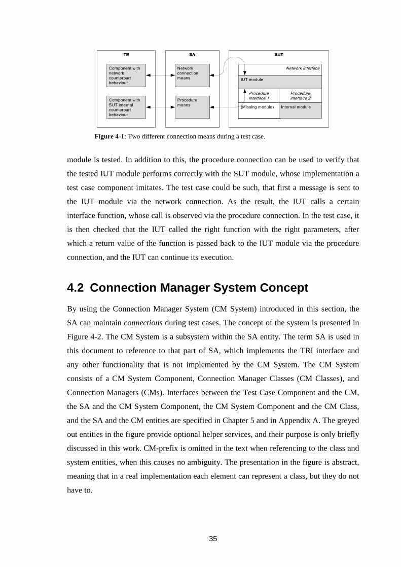
35
module is tested. In addition to this, the procedure connection can be used to verify that
the tested IUT module performs correctly with the SUT module, whose implementation a
test case component imitates. The test case could be such, that first a message is sent to
the IUT module via the network connection. As the result, the IUT calls a certain
interface function, whose call is observed via the procedure connection. In the test case, it
is then checked that the IUT called the right function with the right parameters, after
which a return value of the function is passed back to the IUT module via the procedure
connection, and the IUT can continue its execution.
4.2 Connection Manager System Concept
By using the Connection Manager System (CM System) introduced in this section, the
SA can maintain connections during test cases. The concept of the system is presented in
Figure 4-2. The CM System is a subsystem within the SA entity. The term SA is used in
this document to reference to that part of SA, which implements the TRI interface and
any other functionality that is not implemented by the CM System. The CM System
consists of a CM System Component, Connection Manager Classes (CM Classes), and
Connection Managers (CMs). Interfaces between the Test Case Component and the CM,
the SA and the CM System Component, the CM System Component and the CM Class,
and the SA and the CM entities are specified in Chapter 5 and in Appendix A. The greyed
out entities in the figure provide optional helper services, and their purpose is only briefly
discussed in this work. CM-prefix is omitted in the text when referencing to the class and
system entities, when this causes no ambiguity. The presentation in the figure is abstract,
meaning that in a real implementation each element can represent a class, but they do not
have to.
SUTSUTSUTSUTTETETETE SASASASA
Component with network counterpart behaviour
Component with SUT internal counterpart behaviour
Network connection means
Procedure means
(Missing module)
Network interface
IUT module
Procedure interface 1
Procedure interface 2
Internal module
Figure 4-1: Two different connection means during a test case.
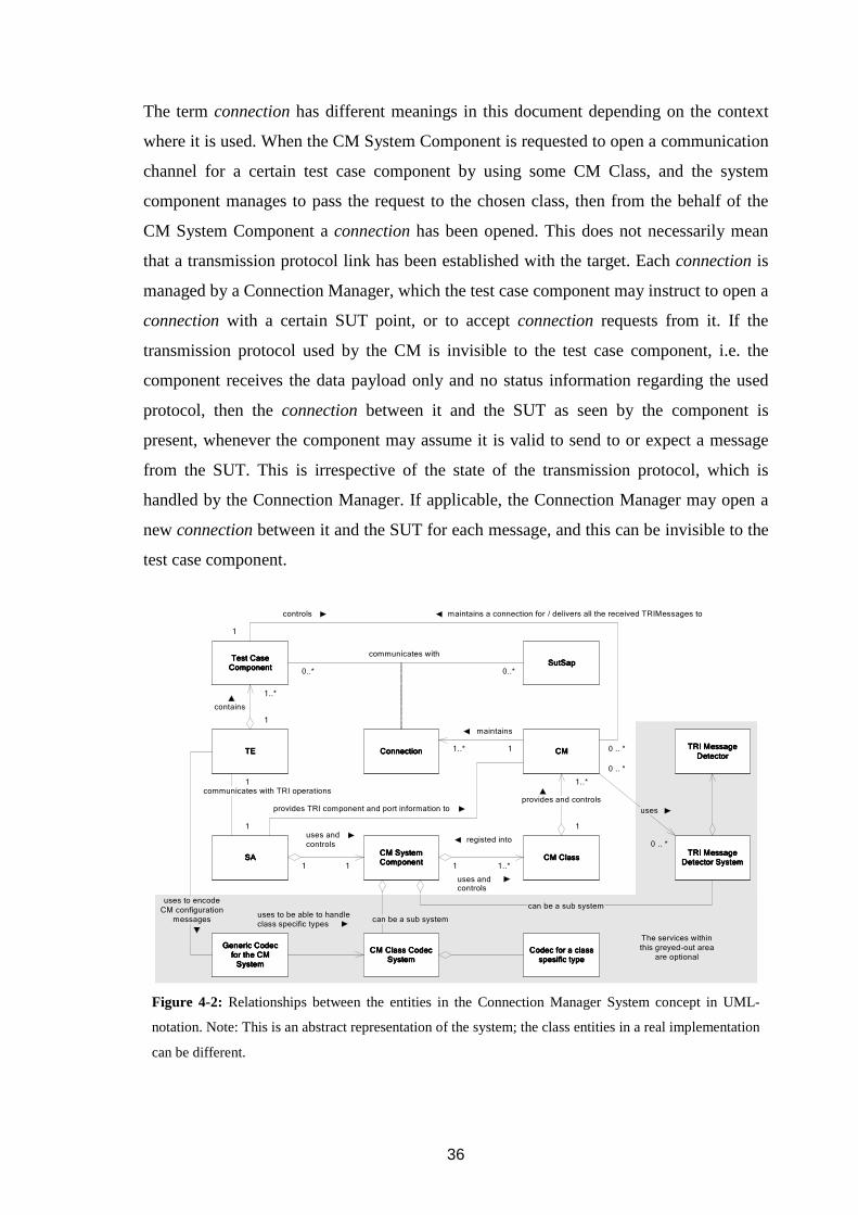
36
The term connection has different meanings in this document depending on the context
where it is used. When the CM System Component is requested to open a communication
channel for a certain test case component by using some CM Class, and the system
component manages to pass the request to the chosen class, then from the behalf of the
CM System Component a connection has been opened. This does not necessarily mean
that a transmission protocol link has been established with the target. Each connection is
managed by a Connection Manager, which the test case component may instruct to open a
connection with a certain SUT point, or to accept connection requests from it. If the
transmission protocol used by the CM is invisible to the test case component, i.e. the
component receives the data payload only and no status information regarding the used
protocol, then the connection between it and the SUT as seen by the component is
present, whenever the component may assume it is valid to send to or expect a message
from the SUT. This is irrespective of the state of the transmission protocol, which is
handled by the Connection Manager. If applicable, the Connection Manager may open a
new connection between it and the SUT for each message, and this can be invisible to the
test case component.
SutSapSutSapSutSapSutSap
SASASASACCCCM M M M SystemSystemSystemSystemComponentComponentComponentComponent
uses and controls
TETETETE
communicates with TRI operations
1
1
registed into
CCCCM M M M ClassClassClassClass11 1..*1
0..*0..*
0..*
Test Case Test Case Test Case Test Case ComponentComponentComponentComponent
contains
ConnectionConnectionConnectionConnection
communicates with
CMCMCMCM
1..*
1
1..*
1
provides and controls
11..*
maintains
0 .. *
1
TRI Message TRI Message TRI Message TRI Message Detector SystemDetector SystemDetector SystemDetector System
TRI Message TRI Message TRI Message TRI Message
DetectorDetectorDetectorDetector
0 .. *
0 .. *
maintains a connection for / delivers all the received TRIMessages tocontrols
uses and controls
Generic CodecGeneric CodecGeneric CodecGeneric Codecfor the CM for the CM for the CM for the CM SystemSystemSystemSystem
CM Class Codec CM Class Codec CM Class Codec CM Class Codec SystemSystemSystemSystem
uses to be able to handle class specific types
uses to encode
CM configuration messages can be a sub system
can be a sub system
Codec for a class Codec for a class Codec for a class Codec for a class spesific typespesific typespesific typespesific type
provides TRI component and port information to uses
The services within
this greyed-out area are optional
Figure 4-2: Relationships between the entities in the Connection Manager System concept in UML-
notation. Note: This is an abstract representation of the system; the class entities in a real implementation
can be different.

37
The purpose of the Connection Manager is to take care of a connection during its
existence, starting from the establishment of the connection to its tear down procedures.
Once the connection has been opened, the Connection Manager handles all the details of
the protocol (or protocols) that forms the transmission means between a test case
component and the SUT. Every Connection Manager belongs to a certain CM Class, and
they can be seen as instances of the class or as entities controlled by the class. Each CM
Class provides certain kind of connection means, or other services, for test case
components, and they all offer the same interface to the CM System Component. The CM
System Component has an interface with the SA, which allows the classes to be
registered into the system, and via which the SA can use the services provided by the CM
System.
Test case writer configures the CMs via a Test System Interface port that has been
selected to be one of the control ports. All the messages the SA receives via the control
port are interpreted as control messages to the CM System Component. If a non-control
message is sent via the control port, it is considered as corrupted message by the
recipient. There can be more than one control ports in the system if this is applicable. In
addition to these CM System configuration ports, there can be dedicated ports for
configuring the SA itself, but that feature is outside the scope of this document. All the
other TSI ports are called data ports, since all the messages received from them contain
encoded data, that the SA delivers to the SUT by using the CM System.
When a component in the TE wants to send a message to a certain SUT address, or to
make a procedure operation, it executes a TTCN-3 communication statement (e.g. send ,
call ) with the following results. The TE calls the TRI communication operation
(triSend() , triCall() ) corresponding to the communication statement to request
the SA to perform according to the statement. Next, the SA constructs a request from the
parameters of the TRI communication operation, and passes it to the System Component
to be handled. The SA does not have to know anything about CMs, classes or their
configuration; it only sees the interface provided by the System Component. Once the SA
has passed the request to the system, it returns from the TRI operation call, without
having to wait for the request to be completed by the system. The System Component
passes the request to the right CM of the used CM Class, which finally transmits the

38
message to the SUT end-point of the connection, or performs a procedure operation such
as function call. Depending on the implementation of the interface functions, the CM
System Component passes the message either directly, or via the CM Class, to the right
CM. The chain of events in sending and receiving direction is show in Figure 4-3.
In the receiving direction the events are simpler: The CM receives a message or
procedure operation from the SUT. After this it requests the TE to enqueue the message
or the procedure operation to the port queue of the right component by using a
triEnqueue * () operation of the TRI interface. These operations require as
parameters the identifier of the receiving component (TriComponentIdType ) and
identifier of the TSI port (TriPortId ) with which the component’s data port has been
mapped. The CM can query for this information from the SA.
Depending on the transmission protocol used by the CM, it is either trivial or not for the
CM to determine in message-based communication when the data received from the SUT
should be enqueued to a component. In the case each transport protocol PDU always
contains data for one test case level message, then the enqueueing is easy, since it can be
done after each received transport protocol PDU. If a single transport PDU may contain
several encoded TTCN-3 messages, or if the messages may arrive in several transport
PDUs, then message detection is needed. This is because the only form in which the CM
can pass the received data to the TE is the form of TriMessageType (Section 3.4
shows the operation signatures), which has to contain all the encoded data that is needed
by a decoder to decode a single value. It is not possible to pass data for several values
simultaneously, or to append more data to the already enqueued data. If the passed data
does not contain a single value in its encoded form, then its decoding will fail and the data
is lost.
TE SA CM System Component
CM SUT SAP
Sending of a message
TE CM SUT SAP
Receipt of a message
CM Class
Figure 4-3: Send and receipt of a message.

39
TRI Message Detector System is an optional system used by the connection managers to
identify messages and their boundaries from the receive data. A single TRI Message
Detector detects message boundaries by a certain general rule, which is either a generic
rule or specific to the messages that are expected be received from the SUT. The message
detectors are independent of the used transmission protocol; they only see a stream of
payload data. The detectors are registered into the TRI Message Detector System, which
offers a single interface via which the detectors can be used. The Connection Manager
may use one or more different detectors on the received data at the same time. The
detector system can be seen as a rough decoder system, which decodes the received data
just enough to be able to determine the message boundaries. The complete decoding is
done later by the TTCN-3 codec system. Further specification of TRI Message Detector
System is outside the scope of this document.
In the following example detection is needed. A Connection Manager uses a connection-
oriented protocol like TCP as the transmission protocol. It is wanted, that the connection
is kept open during the test case so that several TTCN-3 level messages can be exchanged
without having to re-establish the connection after every message. The encoded messages
contain length field as the first field, so the Connection Manager can use a TRI Message
Detector that decodes the length field and keeps track on the received byte count. When
enough data has been received for a complete test case level message (a value of a certain
TTCN-3 type), the detector notifies the Connection Manager about this. In order that the
Connection Manager knows to use a specific message detector, the test case writer has to
configure the CM to use it. This can be done for example at the time when the connection
is opened, by giving the CM a list of used detectors as open-request parameters.
CM Class Codec System is optional system, which can be used to implement generic
codecs for the CM System. The connections with the SUT are configured with CM
System Component specific configuration-message types, which in turn contain CM
Class specific types (5.2 Connection Interface). When a configuration message is sent to
or received from a CM, a codec associated with the configuration message is called, and
this codec should be able do the encoding and decoding of the whole message. The codec
could be a generic one, or there may be an own codec for each of the configuration-
message types. Because it is allowed that each CM Class may use any kind of class

40
specific configuration parameters, the configuration messages contain these class specific
parameter values encoded in a class specific manner. Without a generic codec this is a
problem, for the reason that one should be able to add new CM Classes into the system
without the need to rewrite existing code. If new CM Classes were added into the system,
then in the case of a non-generic configuration-message codec one would have to rewrite
the codec to contain coding instructions for the types of the new classes. For a generic
codec approach the CM Class Codec System provides methods for the configuration-
message codecs to query for class specific codecs by type identifiers and by encoding
attributes, when they are unable to do the encoding on their own. The class specific
codecs can be registered into the CM Class Codec System at the same time when the
classes are registered into the CM System, or at some other time when the tool specific
initialization operations are done (if such exist).
4.3 Requirements
The CM System has requirements at TTCN-3 core language level, and at the SA
implementation language level.
At TTCN-3 core language level is the user, to whom the system should be easy to be used
and hard to be misused. The user should have access only to the configuration parameters
of connection, and not to any meta-data that is meant to be used internally by the system.
In addition to this, any configuration data should be kept separate from any user data,
meaning that when the user tests a certain protocol, the type definitions of this protocol
contain only the message fields of this protocol; there are no extra control fields added to
these type definitions. This allows (or forces) the CM System to deliver the user data
between test target and the test case components transparently, without the need to strip
away and add control data to every sent and received message. All the different
connection types should be configurable using the same methods, and it should be
possible to query status of the connections when required. Addition of new connection
means to the system should not affect the functionality of any existing test cases or other
connection means.

41
At the SA level, the system should provide the possibility to add new transport protocols
into the system easily, without having to do major code modifications into the system.
The CM System may not assume anything about the implementation of the CM Classes.
The user (or test case) should be automatically reported about error situations, such as
when a connection with a target is lost, or the target cannot be reached.
In the terms of performance, the CM System implementation should be as light as
possible; it should only cause minor overhead to the TRI-operation handling. Concrete
performance requirements depend on what is being tested, and what kinds of transport
protocols are used.
4.3.1 Connections
In Figure 4-4, two test case components can be seen communicating with four SUT
addresses over three data connections. Component X has its data port Port 1 mapped to
TSI Port 1. This connection is handled by a connection manager CM A1, which belongs
to CM Class A. Connection Managers of this class use a protocol A to realize at the SUT
the test case statements, that are executed using the component ports. The same
component has another connection via Port 2 to another SUT address. This connection
belongs also to Class A, but it is handled by the manager A2, independently from the first
connection. Component Y uses a single port, Port 1, to communicate with two different
SATRI
CM System
CM Class A
CM Class B
CM A2
TE
System ComponentTSI
Component Y
Component X
Port 1
Port 2
TSI Port 1
TSI Port 2
SUT
csiConnId routes
TriSutAddressType may route
Port 1 TSI Control Port
Control Port
Control Port
CSI
CCI
Protocol B
SAP 1
Protocol BSAP 2
CM A1Protocol A
Protocol A
SAP 1
Protocol A
SAP 2
Protocol B
CM B1
(csiClassId, cciCmId) pair routes
Data connection
Control connection
map-statement routes
Figure 4-4: Connections and identifiers.
42
SUT SAPs. This is possible, because the Class B connection manager uses
sutAddresses to identify two different protocol-B destination addresses. Class B
CMs could be servers, which accept incoming connection requests and data from one or
more SUT addresses, which do not have to be known before the test case. This may be
the case when the protocol B is TCP or UDP, and the operating system of the SUT
assigns any free port addresses to the connections established from it. The protocols used
by the CMs do not have to be network protocols. They can be any methods, like function
calls, with which the CM realizes the intended effect of the TTCN-3 Core Language port
operations at the SUT.
In the same figure Port 2 of Component X and Port 1 of Component Y share the same TSI
port, but both communicate with the SUT over different protocols. It is possible to choose
the used CM Classes independently from the TSI port configuration. This means, that it is
not a prerequisite to have a TSI port of certain name or type specified in a test case to be
able to use a certain CM Class. The test case designer may choose to configure all the
TCP connections via the same “tcp”-titled TSI port, but this is not required by the system.
Every component mapped with a TSI data port has at least one control port, which is
mapped with a TSI control port. This control port of the component is used for
establishing and maintaining the data port connections of the component. The messages
sent by the component via the control port are received by a CM, and the messages the
component receives from it are sent by the CM, hence, there is a bi-directional control
connection between the component and the CM. A single control port can be used to
control several data connections, which are each handler by an own CM, as is the case
with Component X in the Figure 4-4. The CM System Component knows how to route
the control messages to the right CM.
The data port to be configured is identified by a value of type CiTsiPortId , which is
present in every configuration message that is passed between a component and a
connection manager (Section 5.2, Table 5-2, Figure 5-3, Figure 5-4). This value contains
the name of TSI port (text string), with which the data port of the component has been
mapped; it is not the name of the data port of the component. CiTsiPortId uniquely
determines the data port of the component, because according to the standard [T3CORE:

43
s. 8.2] only one port of a component may be mapped with a certain TSI port at a time.
Also, when a message should be delivered to a certain port of a component with a
TTCN-3 Runtime Interface communication operation (Section 3.4), the port is identified
by the name of the TSI port, with which it has been mapped. The TE takes care of passing
of the message to the right port of the component.
Each component may only configure its own data connections. The reason for not
allowing one component to configure a connection via a port of another component is that
the components do not have names or identifiers, which could be used to address them
both at the TTCN-3 language level and at the SA implementation level. At the TTCN-3
language level a component does have component reference that can be stored into a
variable of the type of the component, and which can be used to address a component
within a test case, but this reference value cannot be passed to the CM System via the TRI
interface. This is for the reason that the TCI interface does not provide operations for
encoding and decoding of the values of the component reference kind.
The components may not share connections by simply mapping their own port with a TSI
port, which is already used by another component. If a component has configured a
connection of a certain kind via a certain TSI data port, and another component maps its
data port with the same TSI data port, this second component cannot send or receive
messages or procedure operations via the TSI data port, until the second component has
performed its own port configuration operations. When the SUT sends a message to the
TE via a TSI port, which has been mapped with several components, but only one of them
has configured the TSI port, then the received message is relayed only to the component
that has done the configuration. If they all want to receive messages via the TSI port, they
have to do their own configuration. This restriction comes from the design choice, that
each component may configure an own connection independently via any TSI port,
irrespective of any other possible connections that use the same TSI port. If it is required,
that several components mapped with the same TSI port share the same connection, then
this functionality has to be provided by the used CM Class. In this case, each of the
components may do the configuration by instructing the CM Class, that they want to join
a shared connection.

44
The port of the component used for a data connection must be mapped with a TSI data
port, before the connection through it is attempted to be configured via a control port.
This is required to avoid the situation, in which data is received from the SUT right after
the connection has been opened, and it is directed to a component data port that has not
been mapped to a TSI port. This does not necessarily mean, that data is automatically
started to be received from the SUT when a new connection is opened. It depends on the
used CM Class and its configuration, whether a separate control messages exists, with
which one can instruct a CM to start and stop sending of the received data to the
component.
Once a component has mapped its control port to a TSI control port, and has configured a
connection for a data port, it should remain mapped to the control port for the lifetimes of
all those connections that are controlled via the control port. Because this requirement
cannot be enforced, the SA should instruct the CM System Component to terminate all
the existing connections the component has that are maintained via a control port, when
this control port is unmapped from the TSI control port. In Figure 4-4 this means, that if
Component X unmaps its control port, then the data connections via its ports 1 and 2
become automatically terminated.
When a component does not need anymore a data connection, it should instruct the CM of
the connection to close the data connection. Because this requirement cannot be enforced,
the SA should instruct the CM System Component to terminate the data connection, when
the related data port of the component is unmapped from the TSI data port.
The SA does not need to know which TSI port or ports are used for the control. The CM
System Component performs the identification of the ports on the behalf of the SA.
4.3.2 Identifiers
Each connection is handled by a Connection Manager, which belongs to a certain CM
Class. Every class has to provide at least one manager that can handle at least one
connection at the same time, but there can be several managers running concurrently
within the class, serving several simultaneous connections. It is a design choice of the
class how many connections the class supports at a time, and whether one manager

45
handles them all. Seen from outside the class, each connection is always handled by an
own manager, which has a unique identifier within the class.
All the connection related operations the CM System Component provides to the SA use
an identifier called csiConnId . It can be extracted from the (TriComponentIdType
componentId , TriPortIdType tsiPortId )–pair, which is present in all the TRI
communication operations (Sections 3.4 and 3.5 describe these operation). This identifier
is used by the CM System Component to uniquely identify connections, thus all the CM
System Interface operation calls done with the same csiConnId as a parameter operate
on the same connection. It is worth noticing, that the componentId identifies a test
component, but the tsiPortId identifies a port of the test system interface component.
These types and their contents are shown in Figure 4-5. Types of the internal fields of
TriComponentIdType and TriPortIdType are not shown in the figure, since
these depend on the used language mapping (C, Java) of the TRI interface. The types
used within csiConnId are specified in Section A.1 CM System Interface.
The csiConnId identifier is now defined to be the triplet (componentInstString ,
portNameString , portIndex ) (see Figure 4-5). The componentInstString
is the string stored in the componentInst field of TriComponentIdType
componentId in the ANSI C type definition of TRI language mapping. In Java
mapping, it is the value received with getComponenId() method of the
TriComponentId interface. portNameString and portIndex are the fields of
TriPortIdType tsiPortId .
Within the CM System Component, csiConnId is mapped to the identifier of the
Connection Manager, that is handling the related connection. This CM identifier is called
cciCmId , and it is unique within a CM Class. A CM Class identifier, csiClassId , is
CsiConnId csiConnId
String portNameString
CsiIntegerType portIndex
String componentInstString
TriPortIdType tsiPortId
...
TriComponentIdType compInst
portName
portIndex
TriComponentIdType componentId
compType
compInst
Figure 4-5: Structure of csiConnId .

46
used together with the cciCmId to uniquely identify a CM between classes. The classes
are registered into the CM System Component with their unique csiClassId identifier,
whose value is the field name of the class in the TTCN-3 union type
Ci <OperationName >Params : E.g., a variable CiOpenParams class is a union
value, whose different field names could be .socket , .frameRelay , and .atm .
Each of these serves as the csiClassId identifier of the related class. This is explained
further in Section 5.2.2.
The TriAddress sutAddress value, which is present in the TRI communication
operations as one of the parameters, is not used in the csiConnId . The reason is that its
TTCN-3 core language level form, address value, is optionally present in the
communication operations. If it was used in the csiConnId , then it would have to be
either used, or not used at all, in all the core language level communication statements
(call , send ) concerning a certain connection, because the CM System Component
maps the value of csiConnId to the identifier of CM that handles the connection
(explained later in 4.3.3 Information storage). Its usage would also complicate error
handling in the situation in which connections are closed improperly, because it is not
present in the triUnmap() operation (A.1.2 Operations: csiConnTerminate).
Nevertheless, the address value is always passed transparently by the CM System
Component to the CM Classes. Since the csiConnId is not dependent on the usage of
the address value, the address can be used for example only when a new connection is
opened, and it may be omitted in all the operations after that, if this is permitted by the
used CM Class. The CM handling the connection may use the address values to
address several elements within the SUT by using them as sub-connection identifiers.
4.3.3 Information storage
The CM System and the SA have to maintain information on the connections. It must be
know how components are mapped into Test System Interface, so that the system knows
where the received messages should be delivered to. In order for the CM System to know
what CM Classes are present in the system and how they can be accessed them, a class
register is needed. When data should be delivered to the SUT, it must be known to which
connection the data belongs, and what CM is handling the connection. For each
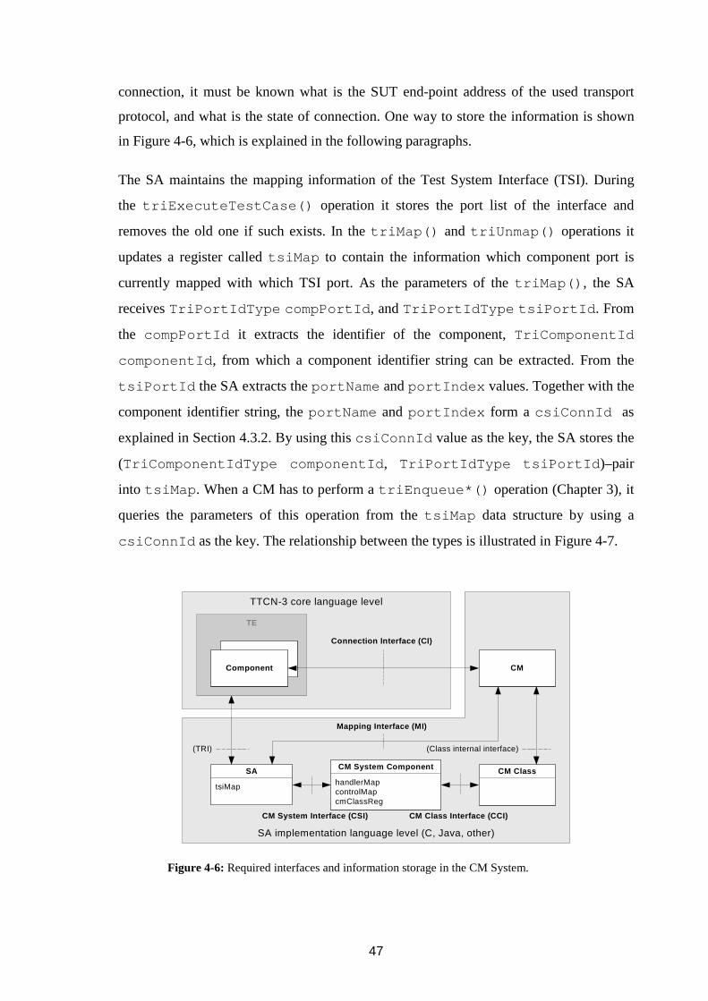
47
connection, it must be known what is the SUT end-point address of the used transport
protocol, and what is the state of connection. One way to store the information is shown
in Figure 4-6, which is explained in the following paragraphs.
The SA maintains the mapping information of the Test System Interface (TSI). During
the triExecuteTestCase() operation it stores the port list of the interface and
removes the old one if such exists. In the triMap() and triUnmap() operations it
updates a register called tsiMap to contain the information which component port is
currently mapped with which TSI port. As the parameters of the triMap() , the SA
receives TriPortIdType compPortId , and TriPortIdType tsiPortId . From
the compPortId it extracts the identifier of the component, TriComponentId
componentId , from which a component identifier string can be extracted. From the
tsiPortId the SA extracts the portName and portIndex values. Together with the
component identifier string, the portName and portIndex form a csiConnId as
explained in Section 4.3.2. By using this csiConnId value as the key, the SA stores the
(TriComponentIdType componentId , TriPortIdType tsiPortId )–pair
into tsiMap . When a CM has to perform a triEnqueue*() operation (Chapter 3), it
queries the parameters of this operation from the tsiMap data structure by using a
csiConnId as the key. The relationship between the types is illustrated in Figure 4-7.
SA implementation language level (C, Java, other)
TTCN-3 core language level
CM ClasshandlerMapcontrolMapcmClassReg
CM System Component
tsiMap
SA
CM
TE
ComponentComponent
Connection Interface (CI)
(TRI)
CM System Interface (CSI) CM Class Interface (CCI)
(Class internal interface)
Mapping Interface (MI)
Figure 4-6: Required interfaces and information storage in the CM System.
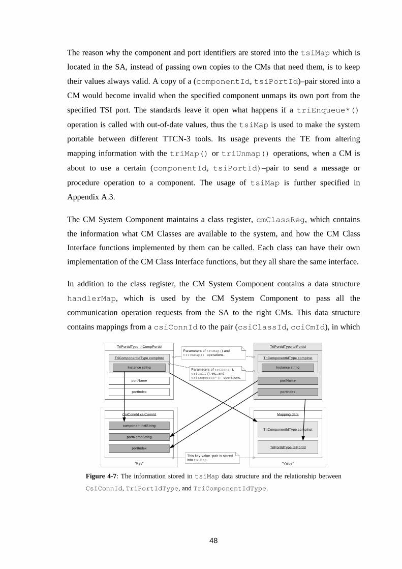
48
The reason why the component and port identifiers are stored into the tsiMap which is
located in the SA, instead of passing own copies to the CMs that need them, is to keep
their values always valid. A copy of a (componentId , tsiPortId )–pair stored into a
CM would become invalid when the specified component unmaps its own port from the
specified TSI port. The standards leave it open what happens if a triEnqueue*()
operation is called with out-of-date values, thus the tsiMap is used to make the system
portable between different TTCN-3 tools. Its usage prevents the TE from altering
mapping information with the triMap() or triUnmap() operations, when a CM is
about to use a certain (componentId , tsiPortId) –pair to send a message or
procedure operation to a component. The usage of tsiMap is further specified in
Appendix A.3.
The CM System Component maintains a class register, cmClassReg , which contains
the information what CM Classes are available to the system, and how the CM Class
Interface functions implemented by them can be called. Each class can have their own
implementation of the CM Class Interface functions, but they all share the same interface.
In addition to the class register, the CM System Component contains a data structure
handlerMap , which is used by the CM System Component to pass all the
communication operation requests from the SA to the right CMs. This data structure
contains mappings from a csiConnId to the pair (csiClassId , cciCmId ), in which
”Value””Key”
TriPortIdType tsiPortId
TriComponentIdType compInst
portName
portIndex
Instance string
Mapping data
TriComponentIdType compInst
TriPortIdType tsiPortId
CsiConnId csiConnId
portNameString
portIndex
componentInstString
TriPortIdType triCompPortId
TriComponentIdType compInst
portName
portIndex
Instance string
Parameters of triMap( ) and triUnmap() operations.
Parameters of triSend( ), triCall( ), etc.,and triEnqeueue*() operations.
This key-value -pair is stored into tsiMap .
Figure 4-7: The information stored in tsiMap data structure and the relationship between
CsiConnId , TriPortIdType , and TriComponentIdType .

49
csiClassId is the class identifier of the CM, and cciCmId is the identifier of the
CM, that is handling the connection (see Figure 4-8). The cciCmIds are generated by
the CM Classes, when the CM System Component requests them to create new managers
to handle new connections. These identifiers are unique within a class. It would be
possible to place a mapping data structure similar to the handlerMap within each class,
but then each class would have to implement it, instead of having it done in one place.
Because of the requirement, that the data connections related to a control connection are
closed when the control connection is terminated, the CM System Component has to
maintain a data structure, which contains the information which data connections are
controlled by a certain control connection, and what is the control connection of a certain
data connection. This information is stored into the data structure called controlMap
(see Figure 4-8).
Each CM Class maintains identifiers of its CMs. When the CM System Component
passes an operation request along with a cciCmId identifier to a CM Class by using CM
Class Interface operations, the class knows from the identifier which CM should handle
the request.
Each CM maintains information on the connection it is handling. Either it knows the
csiConnId of the data connection it is handling and the identifier of the related control
connection, or it asks them from its class. The CM can use the csiConnId to ask from
tsiMap (SA)
componentId, tsiDataPortId
csiDataConnId
componentId, tsiDataPortId
handlerMap(CM Sys. Comp.)
csiClassId, cciCmId
controlMap(CM Sys. Comp.)
componentId, tsiCtrlPortId
csiCtrlConnId
csiDataConnId
componentId, tsiCtrlPortId
csiCtrlConnId
”csiNoConnId”
csiClassId, cciCmId
csiClassId, cciCmId
Data connections of a single component :
Control connection of a single component :
Stand-alone control connection of a single component:
Figure 4-8: Relationship between the mapping data structures and the identifiers. Double-headed
arrow means that the mapping is in both directions.

50
SA the related (componentId , tsiPortId )–pair, which is stored into tsiMap , when
it wants to send messages and procedure operations to a test case component with the
triEnqueue * () operations. When a new data connection is opened (related operations
are A.1.2: csiConnOpen , A.2.2: cciConnOpen ), the csiConnId of the data
connection and its control connection are passed the CM Class, which in turn may pass
them to the CM.
The following summarizes the usage of the mapping data structures shown in Figure 4-8:
The tsiMap maps a csi*ConnId value to a (componentId , tsiPortId )–pair,
which is needed by the CM when it has to pass a message and procedure operation to a
test case component. When a csi*ConnId value identifies a control connection, then
the controlMap is used by the CM System Component to retrieve the identifiers of the
data connections, that are controlled by the control connection. The handlerMap is
used by the CM System Component to map a data connection identifier to the
(csiClassId , cciCmId )–pair, in order to find out which class and which particular
CM is handling the data connection. In the special case when a control connection does
not control any data connection, the identifier of the control connection is used directly
with the handlerMap . The CM System Component uses the csiClassId to find the
right interface functions from its cmClassReg (not shown in the figure), when it needs
to pass a connection related operation to CM of a certain class.
4.3.4 Concurrency
In TTCN-3 Runtime Interface [T3TRI: s. 4.3] it is specified, that all the TRI operations,
except the external function call, are non-blocking. With non-blocking it is meant, that
blocking during a TRI operation may not have any effect on the test system at the test
case level. The non-blocking requirement can be fulfilled by having separate worker
threads and a task queue, into which the TRI operations are enqueued.
To make the CM System independent of the concurrency model of the TE
implementation, and of the SA implementation, all the CM System Interface operations
belonging to the connection category (listed in A.1) must be non-blocking and thread-
safe. All the system and class category operations of CM System Interface are thread-safe

51
but blocking. They are blocking because they are initialization and finalization related
operations. It is wanted that they do not return until their intended effect has been
completely performed, so that the state of the CM System can be guaranteed after these
operations.
4.3.5 Operation handling order
When a test case component performs a sending operation (send , call , etc.) on a port
that is mapped with a TSI port, this results in a corresponding TRI operation. In TTCN-3
Runtime Interface Standard [T3TRI] it is specified, that as the result of a TE-initiated TRI
communication operation, the SA can act according to the operation. It is not required
that the SUT has experienced the intended effect of the operation before the TRI
operation returns, thus the operation can be delayed by buffering it into a queue. How and
when the operations are handled is outside the scope of the standard. The CM System
provides the SA the means to handle the TRI operations. With operation handling order
it is meant the order in which the CM System Component, the CM Classes, and the CMs,
process the operation request the SA makes to the CM System. This order is not self-
evident; it depends on the interpretation of the test system interface, and on what is
wanted.
On interpretation of the test system interface
The test system interface is an abstract interface, which in some way provides a mapping
to the real interface(s) of the SUT. It is not specified where this abstract interface is
located. It can be though of being located at the SUT, or at the TE or SA, or somewhere
in between.
If it is assumed that the ports of the TSI reside at the SUT as illustrated in Case A of
Figure 4-9, and that a mapping between a component port and a TSI port works the same
way as a connection between two component ports, then it could be assumed that all the
port operations performed on a component port mapped with a TSI port are seen at the
TSI port in an unchanged order. It would be up to the SA or the CM System to make sure
the operations appear in order at a SAP of the SUT. Of course, one might argue that the
propagation of messages from a component port to a TSI port does not have the same

52
meaning as when they move between two component ports, and it is subject to effects of
the used transmission means, but this would make it harder to write test cases in which
the order of events is guaranteed.
If it is assumed, that the TSI ports are at the SA as show in the Case B in Figure 4-9, do
the operations now have to be guaranteed to be experienced by the SUT in the same order
in which they are executed in a test case? The answer to this is not necessarily. If the
communication with the SUT can only be accomplished by using a connectionless
protocol like UDP, and the SUT has been designed and intended to communicate over
this unreliable protocol, it would not make sense to build such a mechanism into the SA,
CM System or the SUT, that ensures unchanged packet order during transmission. In this
case, the person who runs the test cases should ensure that the transmission network used
in the test system is simple enough not to introduce any changes to the packet order.
Because the situation B in Figure 4-9 gives more freedom on what kind of transmission
means can be used, that interpretation is chosen in this document. It does not mean that
the operation order is never preserved, but that it can be an optional feature of the used
CM Class.
Operation handling within the CM System Component
Because the test case components or ports have no execution priority, it is natural that all
the communication operation requests are handled by the CM System Component in the
first-come, first-served manner. The CM System entity does not have understanding on
SUT
SUT
Component
Transmission meansComponent
Real test system interface
Abstract test system interface (TSI)
SAPTSI portPort
Transmission means
Real test system interface
Abstract test system interface (TSI)
SAPTSI portPort
B)
A)
Figure 4-9: Two interpretations of the location of the TSI.

53
the parameters with which connections have been configured, thus they have no effect on
the handling order. When the SA has requested the CM System to perform connection
related operations by using the CM System Interface operations (A.1.2 Operations), the
CM System may choose to enqueue these operation requests into a list, or it may handle
the operations directly, but it may not change their relative order. With the handling it is
meant, that CM System Component passes the requests to the right CM Classes and CMs.
Operation handling within a CM Class
The CM System Component requests the CM Classes to perform connection related
operations by using the CM Class Interface (CCI) as specified in A.2.2 Operations. The
identifier of the CM that is handling the connection is present in these operations. The
order in which the CM Class forwards the operation request concerning a single
connection to a specific CM is the same as in which they have been requested to be done
by the CM System Component.
However, it is allowed that the relative order of operation requests that are directed to
different CMs (i.e. do not belong to the same connection) does not need to be preserved.
This is because a CM Class could provide priority parameters for the connections, and
since each connection is handled by an own CM, the priority of the connection is the
priority of the CM. Any requests directed to the CMs may be forwarded to them in a
manner, which takes the priority in account. This feature could be used in high-load
situations.
Operation handling between CM Classes
It is not required the classes to preserve handling order over the class boundaries. This is
to allow the classes to provide any kind of transport means to the user: slow or fast, with
or without guaranteed transmission order. If the classes did have a common
synchronization for preserving the operation handling order, this might cause problems
for example in the case, where the buffered operations of a slow connection class block
the usage of faster connection class, until all the operations have been handled.

54
Some of the classes may provide mutual synchronization, but this should be an optional
user configurable feature, unless these classes are meant to be used together and their
functionality requires this.
Operation handling within a CM
Each CM preserves the relative order of the requests concerning a connection it is
handling, unless the optional address parameter of the TTCN-3 communication
statements is used by the CM as a sub-connection identifier.
If the SUT address is used by the CM to identify sub-connections, then it depends on the
used CM Class and configuration parameters of the connection in which order the
operation requests are handled.
With the handling within a CM it is meant, that the CM interacts with the SUT when the
requested operation requires this, but it does not say anything about the order in which the
SUT experiences the results of the operations. There is a possibility that the operations
become rearranged during transmission, if the transport protocol used by the CM does not
guarantee in-order transmission.
Operation handling between CMs of different classes
As it is not required to have synchronization between different CM Classes, it is not
required to have synchronization between the CMs of different classes.
An example situation where synchronization would be harmful is two connections, one
using a CM Class, which uses TCP as the transport protocol and is used for data, and
another one using UDP and is used for control messages for controlling the TCP data
connection. If the sending order of the messages was preserved between the classes, and
if the send buffer of the TCP connection becomes full, then no control messages via the
UDP connection can be sent until all the TCP data has been sent to the SUT. The situation
would be even worse if the two connections were unrelated. For example, there could be
one component using a UDP connection for completely other purpose than to control the
TCP connection. This other UDP connection might be used for some kind of heartbeat
protocol, which requires a transmission of a message at fixed intervals. It would not make

55
sense if the sending problems with TCP data connection affected the UDP connection,
since their purposes are unrelated.
Operation order at test case level
When writing a test case, in which a component communicates with several targets over
several protocols, the test case writer has to choose and configure the used CM Classes
and CMs so that they do preserve the test case’s intended delivery order of messages and
procedure operations. This is not guaranteed by default and depends on the context and
the used CM Classes.
It should be noted, that when a CM passes a message or a procedure operation to a
component via some specific TSI port, lets say “Port A”, by using a TRI interface
triEnqueue*() operation, and then passes another message or procedure operation
via other TSI port “Port B”, the receiving component cannot automatically determine
which event occurred the first. The messages or the parameters of the procedure operation
needs to contain a timestamp or sequence number, with which the test case component
can reconstruct the order of events if this is needed, because TTCN-3 core language does
not provide means to determine or compare the order of events between two ports.

56
5 INTERFACES This chapter specifies the functionality of the following interfaces: Connection Interface
(CI), Mapping Interface (MI), CM System Interface (CSI), and CM Class Interface (CCI),
which are shown in Figure 4-6. Of these, the Connection Interface is specified in detail,
because it can be thought as TTCN-3 Core Language level user interface to the services
provided by the CM System, thus making it of interest to the test case writer.
Understanding it also helps in understanding what the other interfaces try to accomplish.
The Mapping Interface, CM System Interface, and CM Class Interface are “under the
hood” at SUT Adapter level, so only an overview of them is given in this chapter. These
interfaces are used for keeping TSI port information consistent (tsiMap ), for registering
new CM Classes into the system, and for using their services to communicate with the
SUT. Their detailed description can be found in Appendix A. Selected MSC diagrams
showing how the operations of the interfaces work together can be found in Appendix B.
5.1 Notation
All the interface operation in this chapter and in Appendix A are specified using the
following format:
Operation identifier (Caller or Sender ���� Callee or Recipient)
In: The parameters passed from the caller to the callee.
Out: The parameters passed from the callee to the caller.
Return: Return value of the operation.
Purpose: Description what the operation is used for.
When: Description when the operation is performed and what triggers it.
The parameters and return values are in format:
TypeIdentifier variableIdentifier
Operation has no mandatory parameters or return value if the corresponding part has
been omitted in the text.

57
The operations and data types are specified at an abstract level. It is not required that
every operation exist in an actual implementation, which may be done in C or Java
language. The operations describe what needs to be done, and the in part and out part
describe the mandatory information that is passed between the caller and the callee in the
operations. It is not considered how the parameters are passed, when memory is allocated
and freed, or what is the representation format of the types in an actual implementation.
The language mappings from the abstract operations and data types to C or Java are not
defined in this work.
An example situation in which the implementation does not need to follow the abstract
definitions is the csiConnDecodeOp() of CM System Interface. This operation is
called by the SA to determine which CM System Interface operation it should use to
handle a triSend() operation call. It is possible to replace all the connection category
operations (excluding csiConnTerminate ) with a single operation, which performs
the action of csiConnDecodeOp() and then calls the right operation directly, instead
of returning the identifier of the right operation to the SA, and having it call the right
operation. This would make the interface simpler for the SA, but it would unnecessarily
complicate the specification of the different steps that need to be done.
5.2 Connection Interface
Connection Interface contains the operations needed to configure connections between
component ports and the SUT (control operations), and for using them for communication
(data operations). All the control operations are realized with the message-based send
and receive statements, with a particular TTCN-3 type as the parameter. The data
operations consist of all the TTCN-3 port operations that are used for communication
with the SUT via a data port (send , call , reply , raise ). All the operations of the
Connection Interface are listed in Table 5-1.
5.2.1 On design choices
One reason for defining the Connection Interface control operations as message-based,
instead of using procedure statements, is the simpler syntax of the message statements at
the TTCN-3 core language level, and simpler parameters at the TRI interface.
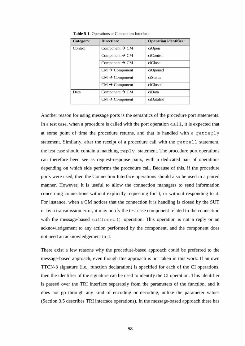
58
Another reason for using message ports is the semantics of the procedure port statements.
In a test case, when a procedure is called with the port operation call , it is expected that
at some point of time the procedure returns, and that is handled with a getreply
statement. Similarly, after the receipt of a procedure call with the getcall statement,
the test case should contain a matching reply statement. The procedure port operations
can therefore been see as request-response pairs, with a dedicated pair of operations
depending on which side performs the procedure call. Because of this, if the procedure
ports were used, then the Connection Interface operations should also be used in a paired
manner. However, it is useful to allow the connection managers to send information
concerning connections without explicitly requesting for it, or without responding to it.
For instance, when a CM notices that the connection it is handling is closed by the SUT
or by a transmission error, it may notify the test case component related to the connection
with the message-based ciClosed() operation. This operation is not a reply or an
acknowledgement to any action performed by the component, and the component does
not need an acknowledgement to it.
There exist a few reasons why the procedure-based approach could be preferred to the
message-based approach, even though this approach is not taken in this work. If an own
TTCN-3 signature (i.e., function declaration) is specified for each of the CI operations,
then the identifier of the signature can be used to identify the CI operation. This identifier
is passed over the TRI interface separately from the parameters of the function, and it
does not go through any kind of encoding or decoding, unlike the parameter values
(Section 3.5 describes TRI interface operations). In the message-based approach there has
Table 5-1: Operations at Connection Interface.
Category: Direction: Operation identifier:
Component � CM ciOpen
Component � CM ciControl
Component � CM ciClose
CM � Component ciOpened
CM � Component ciStatus
Control
CM � Component ciClosed
Component � CM ciData Data
CM � Component ciDataInd

59
to be a separate operation identifier field in the transfer syntax of the messages (specified
in Section 5.2.3), which has to be decoded and extracted by the recipient. This work could
be avoided by using the procedure-based approach. In the procedure-based approach it is
easier to access the different function parameter values, since they can be read from the
parameter list. In the message-based approach they are concatenated as sequence of bytes
and the recipient has to figure out when one parameter value ends and the next one starts.
However, the overhead in the message-based approach is minimal, because of the few
number of parameters. In the procedure-based approach the decoding of the parameters is
slightly easier, since the TE knows to call the right decoders directly, meaning the
decoders assigned to the parameter types. In the message-based approach, the TE has to
attempt to decode from the received data a value of any of the types, that can be received
from the used port, and which are being expected by the component. For example, if a
component expects in an alt statement either a ciOpened or a ciClosed message,
and a ciClosed message is sent by the CM, then a decoding attempt is possibly first
made for the ciOpened type, and when this fails, a second successful attempt is made
for the ciClosed type. These unsuccessful decoding attempts have no real effect on the
performance though, since a CI operation decoder can decide from the first decoded bytes
of the received data which CI operation is in question (5.2.3: Table 5-3), thus it can tell
immediately without further decoding whether the decoding will be successful or not.
Instead of doing the configuration via dedicated control ports with messages or procedure
calls, one might consider using action statements or external function call
statements. The problem with the action statements is that information can only be
passed in the direction of from the test case to the SA. Hence, the receipt of any
acknowledgements or status reports from the SA has to be implemented in some other
way. In addition to this, the next version of the TTCN-3 standard possibly allows only the
passing of textual data with the action statement; it is not possible to pass a value or a
template with this mechanism any more [T3MOCKUP: s. 26]. By using the external
function calls it is possible to return information back to the test case, but the problem is
that the resulting triExternalFunction() call is blocking; it will not return until
the invoked external function has returned. If the TE is implemented with a single
execution thread, then the whole test system becomes blocked for the duration the of

60
connection establishment with the SUT, if the ciOpen() operation is implemented as an
external function call. The ciOpened() operation would in this case be implemented as
the return value or out-parameter of the external function. Depending on the used CM
Class, it may take some time before the connection has been opened and the
triExternalFunction() can return. This time may be long enough to affect the
behaviour or the result of the test case that is being executed, which should not happen.
5.2.2 Type definitions
The TTCN-3 type definitions specified in the end of this section (Figure 5-3) are used to
define the Connection Interface operations. Their encoding and encoding attributes are
discussed in the Section 5.2.3, and their usage is explained in the Section 5.2.4.
Connection Interface operation message types can be defined in several ways in TTCN-3
Core Language. The following aspects need to be considered when deciding what kind of
type definitions will be used for the Connection Interface operation message types, and
for the CM Class specific parameter-type definitions.
Firstly, the information content of the Connection Interface operation messages go
through two or three different representation formats when they are used. In a test case,
the Connection Interface operation messages are defined and used in some TTCN-3 core
language representation format. When the messages are sent, the CM System Component
receives them in an encoded form, since all messages that are sent via a TSI port are
encoded by the codec system. Before the CM System Component can use the received
message, it may have to decode it to a more suitable internal format.
Secondly, there are two kinds of information present in the operation messages. The first
kind is the information that is used to control the connections and which the test case
writer can set. This information comprises the connection establishment parameters, SUT
addresses, and so on. The second kind of information is the meta-data needed by the CM
System to be able to handle the operation messages. This consists of message identifiers,
type identifiers, class identifiers, data length values, and so on, which should be of no
concern to the test case writer.

61
If the types are defined in a way, in which the data is structured in TTCN-3 language
form close to how it is structured in the format in which it is to be sent to the CM System,
the encoding and decoding of the data becomes easier. An example of this is shown in
Figure 5-1. A TTCN-3 record, which contains IP addresses and port numbers for both the
TE and the SUT, is supposed to be encoded into a consecutive string of bits. If the IP
addresses and port addresses are separated into two different records, like in HeaderA ,
and the transfer syntax is such as shown in the figure, then the encoding becomes more
difficult. Either the codec has to encode the two internal records simultaneously to be able
to encode the information consecutively, or it encodes one record first and leaves empty
space holder in the encoded bit string, and fills in this space later while processing the
second record. Why this kind of situation could be wanted to be avoided is that there
could be a generic codec that is designed to encode any record type. One could call it
recursively to process nested records, but it would be difficult to encode the HeaderA
with it because of the used transfer syntax.
If the types are defined in the way the data is used by the CM System, the data handling
becomes easier to the CM System, but to the test case writer the system might become
harder to use, since the use might need to have internal understanding on the
implementation of the used transport protocols and the CM System. For example, it
would be convenient for a CM Class providing connections over Unix Sockets, if the
received control data contained: a filled in struct sockaddr value to be used with
connect() function, an address family value, a socket type value, and a protocol
type record HeaderA
type record IpAddrs
Source IP
Destination IP
type record PortAddrs
Source Port
Destination Port
type record HeaderB
Source IP
Source Port
Destination IP
Destination Port
Source IP
Source Port
Destination IP
Destination Port
Transfer syntax:
TTCN-3 type definition: TTCN-3 type definition:
1.
2.
3.
4.
Figure 5-1: Two different type definitions for the same data.
62
specifier value to be used with socket() function [UNIX: ch. 4]. However, for a user
with no knowledge on socket programming the usage of these parameters would be
difficult.
A user friendlier approach is to define types in such a way, that they give a higher-level
abstraction of what is provided, without the possibility to unintentionally set illegal
parameter combinations, or to change the values of the meta-data used by the CM
System. The values used within the implementation of the CM System can be derived
from higher-level parameters by combining them with extra information, which is stored
in the form of type definitions and the type attributes of the control messages. This
approach is used with the types defined at the Connection Interface. At the encoding
phase the codecs can add the extra information to the to-be-sent data based on the type
identifiers, type classes and type attributes. The type classes are defined in [T3TCI: s.
7.2.2.1], and they specify the base or root type of any user specified type: e.g. integer,
record, set of, and so on. At the decoding phase, the codecs can use the extra information
within the received data to build the right TTCN-3 types.
In the case of a CM Class providing connections over Unix Sockets, the type definitions
for its connection-parameter types could be as outlined in Figure 5-2. By using the type
definitions shown in the figure, the test case writer can only define a valid set of
properties for a connection because of how the information has been grouped and
structured. For example, it is not possible to mistakenly define a TCP connection with
options from the UDP class, or to require that the local port uses TCP but the destination
port uses the UDP protocol. When encoding the values into transfer syntax form, the
encoder is responsible for adding the information which alternative of a union is present
in the data.
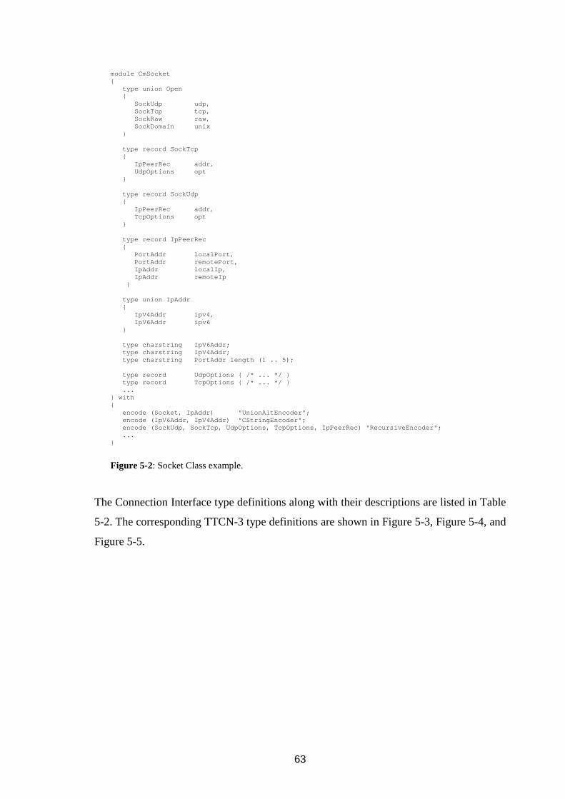
63
module CmSocket { type union Open { SockUdp udp, SockTcp tcp, SockRaw raw, SockDomain unix } type record SockTcp { IpPeerRec addr, UdpOptions opt } type record SockUdp { IpPeerRec addr, TcpOptions opt } type record IpPeerRec { PortAddr localPort, PortAddr remotePort, IpAddr localIp, IpAddr remoteIp } type union IpAddr { IpV4Addr ipv4, IpV6Addr ipv6 } type charstring IpV6Addr; type charstring IpV4Addr; type charstring PortAddr length (1 .. 5); type record UdpOptions { /* ... */ } type record TcpOptions { /* ... */ } ... } with { encode (Socket, IpAddr) "UnionAltEncoder"; encode (IpV6Addr, IpV4Addr) "CStringEncoder"; encode (SockUdp, SockTcp, UdpOptions, TcpOptions , IpPeerRec) "RecursiveEncoder"; ... }
Figure 5-2: Socket Class example.
The Connection Interface type definitions along with their descriptions are listed in Table
5-2. The corresponding TTCN-3 type definitions are shown in Figure 5-3, Figure 5-4, and
Figure 5-5.

64
Table 5-2: Connection Interface type definitions.
Type Identifier: Description:
CiOpen ciOpen() operation is performed, when a value of this record type is sent
by a component via its control port to a CM. It contains fields of type
CiTsiPortId (optional) and CiOpenParams (mandatory).
CiOpened ciOpened() operation is performed, when a value of this record type is
sent by a CM to a component via its control port. This type contains fields
of type CiTsiPortId (optional) and CiOpenedParams (mandatory).
CiClose ciClose() operation is performed, when a value of this record type is
sent by a component via its control port to a CM. It contains fields of type
CiTsiPortId (optional) and CiCloseParams (mandatory).
CiClosed ciClosed() operation is performed, when a value of this record type is
sent by a CM to a component via its control port. This type contains fields
of type CiTsiPortId (optional) and CiClosedParams (mandatory).
CiControl ciControl() operation is performed, when a value of this record type is
sent by a component via its control port to a CM. It contains fields of type
CiTsiPortId (optional) and CiCloseParams (mandatory).
CiStatus ciStatus() operation is performed, when a value of this record type is
sent by a CM to a component via its control port. This type contains fields
of type CiTsiPortId (optional) and CiStatusParams (mandatory).
CiTsiPortId A value of this record type is used to identify a TSI port. It contains fields
CiTsiPortName (mandatory) and CiTsiPortIndex (optional).
CiTsiPortName Subtype of TTCN-3 charstring type. A value of this type is used to
identify a TSI port (array) by its name. The TSI port (array) name is one of
the port identifiers of the component that is being used as the system
component.
CiTsiPortIndex Subtype of TTCN-3 integer type. A value of this type is used to
identify a particular port in a port array that is identified with the field
CiTsiPortName name of CiTsiPortId type. The special value omit
of denotes that CiTsiPortName refers to a single port instead of a port
array. Any other non-negative refers to an element of the array. The omit
value is encoded as –1 (see Table 5-3), which is in line with Java and C
language mappings of the type TriPortIdType [T3TRI: ss. 6.3.2.1 and
7.2.1].

65
Table 5-2: Connection Interface type definitions.
Type Identifier: Description:
CiOpenParams This union of CM Class specific types contains parameters for opening a
new connection. For example, it can contain peer addresses for the used
connection protocol, buffer sizes, and so on. The field names of the union
are used as the identifiers of the CM Classes at CM System Interface.
CiOpenedParams This union of CM Class specific types contains parameters for an opened
connection. A CM Class can use this type to return information about the
opened connection to the test case. The field names of the union are used as
the identifiers of the CM Classes at CM System Interface.
CiCloseParams This union of CM Class specific types contains parameter for closing a
connection. For example, it may contain information about what should be
done with any possibly buffered data, or with the data that is possibly
received from the SUT after it has been instructed to close the connection.
The field names of the union are used as the identifiers of the CM Classes
at CM System Interface.
CiClosedParams This is a union of CM Class specific types with which the CM can return
any information about the connection that was closed. For example, it may
contain a status report telling whether the connection was closed cleanly or
if there were any problems. The field names of the union are used as the
identifiers of the CM Classes at CM System Interface.
CiControlParams This union of CM Class specific types can be used to implement any CM
Class specific extra functionality that involves sending a message to the
CM Class or CM. For example, parameters of opened connections can be
modified with this type. The field names of the union are used as the
identifiers of the CM Classes at CM System Interface.
CiCfgPort This port type is used to define Connection Interface control ports.
CiStatusParams This union of CM Class specific types can be used to implement any CM
Class specific extra functionality that involves sending a message from a
CM Class or CM to a test case component. For example, this can contain a
status report of a connection that has been established with the SUT. The
field names of the union are used as the identifiers of the CM Classes at
CM System Interface.
(continued from the previous page)
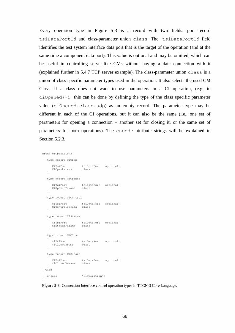
66
Every operation type in Figure 5-3 is a record with two fields: port record
tsiDataPortId and class-parameter union class . The tsiDataPortId field
identifies the test system interface data port that is the target of the operation (and at the
same time a component data port). This value is optional and may be omitted, which can
be useful in controlling server-like CMs without having a data connection with it
(explained further in 5.4.7 TCP server example). The class-parameter union class is a
union of class specific parameter types used in the operation. It also selects the used CM
Class. If a class does not want to use parameters in a CI operation, (e.g. in
ciOpened() ), this can be done by defining the type of the class specific parameter
value (ciOpened.class.udp ) as an empty record. The parameter type may be
different in each of the CI operations, but it can also be the same (i.e., one set of
parameters for opening a connection – another set for closing it, or the same set of
parameters for both operations). The encode attribute strings will be explained in
Section 5.2.3.
group ciOperations { type record CiOpen { CiTsiPort tsiDataPort optional, CiOpenParams class } type record CiOpened { CiTsiPort tsiDataPort optional, CiOpenedParams class } type record CiControl { CiTsiPort tsiDataPort optional, CiControlParams class } type record CiStatus { CiTsiPort tsiDataPort optional, CiStatusParams class } type record CiClose { CiTsiPort tsiDataPort optional, CiCloseParams class } type record CiClosed { CiTsiPort tsiDataPort optional, CiClosedParams class } } with { encode "CiOperation"; }
Figure 5-3: Connection Interface control operation types in TTCN-3 Core Language.

67
Figure 5-4 contains example type definitions of the class unions of ciOpen ,
ciOpened , ciClose and ciClosed operation messages, and the definition of the
control port. Selecting a union alternative of Ci<OperationName>Params
determines the used CM Class. The union alternative identifiers (socket ,
frameRelay ) identify the classes at the CM System Interface. The TTCN-3 type
identifiers of the alternatives are irrelevant to the CM System (CmSocket.Open ,
CmFrameRelay.Open ), making it possible to rename the modules and types used by
the classes without affecting the CM System.
Each component may only configure its own ports; therefore, no component identifier
field is present in the operation messages. All the Connection Interface control operations
are performed via ports of type CiCfgPort , the TTCN-3 definition of which is given in
group ciFieldTypes { type charstring CiTsiPortName length (1 .. infinity); type integer CiTsiPortIndex (0 .. infini ty); type record CiTsiPort { CiTsiPortName name, CiTsiPortIndex index optional } type union CiOpenParams { CmSocket.Open socket, CmFrameRelay.Open frameRelay, CmLangCModuleTest.Open langCModTest, CmLangJavaModuleTest.Open langJavaModTest ... } type union CiOpenedParams { CmSocket.Opened socket, ... } type union CiCloseParams { CmSocket.Close socket, ... } type union CiClosedParams { CmSystem.Closed sys, //See Section 5.3 Error Handling CmSocket.Closed socket, ... } ... } with { encode (CiOpenParams, CiOpenedParams, CiClose Params, CiClosedParams, CiControlParams, CiStatusParams) "CiOperationParams"; encode (CiTsiPort) "CiTsiPort"; }
Figure 5-4: Field types of the Connection Interface operation-message types.

68
Figure 5-5. The Connection Interface data operations are performed via any other user-
defined port types.
5.2.3 On transfer syntax and encoding
Because all the CI operations are implemented as TTCN-3 types, the test case initiated CI
operations are seen at TRI interface as triSend() calls, where all the CI operation
information is encoded within the TriMessageType sendMessage parameter of
the TRI operation. Similarly, every CM or CM Class initiated CI operation is seen by the
decoders of the codec system of the TE as a string of bytes within the
receivedMessage parameter of the triEnqueueMsg() operation. Table 5-3
defines abstract transfer syntax for the CI operations, in which the operations are passed
between the test case components and the CM System. The actual encoding of the fields
depends on the implementation language. The endianness of the computer in which CM
System is being executed may also affect the encoding, unless it is decided that all the
values are always encoded in network byte order.
The CI operation messages in the format of Table 5-3 are referred to being in format
CmSysControlMessage . All the fields are interpreted as a consecutive sequence of
bytes. The position column tells the relative order of the fields, which may be stored into
one or more bytes each. When needed in encoding and decoding, the total length of the
CmSysControlMessage can be retrieved from sendMessage and
receivedMessage , within which the codecs of the TE and the CM System receive the
messages.
type port CiCfgPort message { // To the CM System: out CiOpen; out CiControl; out CiClose; // From the CM System: in CiOpened; in CiStatus; in CiClosed; }
Figure 5-5: Connection Interface port types in TTCN-3 Core Language.

69
Table 5-3: Connection Interface transfer syntax.
CmSysControlMessage
Pos. Field name Description
1
CiOperationId
Fixed width value that is used by the codecs of the TE and the CM System
Component to identify the CI operation in question. The encoder that
handles the CI operation type, or types, derives the right value based on the
type identifier of the value that is being encoded, i.e. CiOpen, CiClose,
CiStatus, etc. The value is encoded in the same representation format as the
CsiCiOpIdType (Table A-2) has in the implementation of the CM
System.
2
TsiPortNameLen Fixed width value that tells the number of bytes used for the
TsiPortName field. The value is encoded in the same representation
format as the CsiIntegerType (Table A-2) has in the implementation of
the CM System. This value is 0, when the tsiDataPort field has been omitted
in CI operation message.
3
TsiPortName Variable width value that contains the name of the target port of the
operation (value of tsiDataPort.name ). The value is encoded as a
sequence of values of type CsiCharacterType (Table A-2) of length
TsiPortNameLen , in which each CsiCharacterType is in the
representation format used by the CM System. This value is not present
when TsiPortNameLen is 0.
4
TsiPortIndex Fixed width value that identifies the target port index of the operation (value
of tsiDataPort.index ). The value is encoded in the same
representation format as the CsiIntegerType has in the implementation
of the CM System. This value is -1, when the tsiDataPort.index has
been omitted in the CI control message.
5
ClassIdLen Fixed width value that tells the number of bytes used for the ClassId
field. The value is encoded in the same representation format as the
CsiIntegerType has in the implementation of the CM System.

70
Table 5-3: Connection Interface transfer syntax.
Pos. Field name Description
6
ClassId Variable width value, which identifies the CM Class that handles the CI
operation. The codec that handles encoding of the class field of the CI
operation messages derives this value from the field name of the currently
selected union alternative, for example class.socket . TCI-CD
operation TString getPresentVariantName() [T3TCI:s.
7.2.2.2.15] can be used to determine the field name. The value is encoded
as a sequence of values of type CsiCharacterType of length
ClassIdLen , in which each CsiCharacterType is in the
representation format used by the CM System.
7
ClassDataLen This fixed width value contains the length of ClassData field. The value
is encoded in the same representation format as the CsiIntegerType has
in the implementation of the CM System.
8
ClassData This value contains the value of the selected union alternative encoded in a
class specific format, e.g. class.socket . It is encoded as a byte
sequence of length ClassDataLen .
When the CM System implementation language is C and fixed-length fields are used, it
might be a tempting idea to do the encoding and decoding by type casting. Because the
CmSysControlMessage uses variable length fields, this kind of decoding cannot be
used for the whole CmSysControlMessage . However, for the class specific data part
this could be done in the following way.
To encode a structured value, one could fill in a corresponding C-struct with the right
values, and then interpret the structure as a sequence of bytes by giving a char pointer to
it. Care must be taken when decoding the data back into the C-struct type because of the
data type alignment used by the processors. When a codec encodes a TTCN-3 value into a
sequence of bytes to be transmitted over TSI, a pointer value to this byte sequence gets
stored into a TriMessage sendMessage (or into receivedMessage in the case of
decoding of a value). When the sendMessage passes through the TRI interface, there is
no guarantee by the TTCN-3 standards that the pointer value within sendMessage is
the same as the one set by the codecs; it could point at a copy of the data, which may be
differently aligned in memory than the original data. Thus, simply type casting the data
and reading the fields may cause hardware exception in certain environments because of
(continued from the previous page)

71
the misaligned data. Therefore, the data in the sendMessage should be copied into a
new memory location with the same byte alignment as the type has, i.e. into a value of the
type, before accessing the fields within the data. The compiled CM System and the
codecs need also to have a common understanding about any possible padding in the
structures and ordering of the fields, which may depend on the compilation parameters.
Because of these problems, it is safer to do the encoding and decoding one field at a time.
There are no standardized methods with which one could gain access to a codec, but it
would be very useful to be able to call a codec from another codec. Some TTCN-3 tools
provide their own methods with which the codecs can be queried and called, but using
these makes the codecs tool dependent. If the tool does not provide these operations, then
the root codec of a structured type has to know how to encode the whole structure from
top down to its atomic nodes. For example, if one has written type definitions with
encoding rules for a PDU of a protocol and codecs for it, and later on would want to
encapsulate this PDU within a PDU of another protocol, then it would be nice if the codec
of the outer PDU could call the codec of the inner PDU to do its encoding. Otherwise, the
outer PDU codec has to re-implement the codec of the inner PDU.
If the tool does not provide its own methods for accessing codecs from codecs, or if the
encoding is wanted to be as tool independent as possible, it might be worth implementing
an own codec system, which provides methods for registering codecs into it by type
identifiers, type classes, encoding attributes, or by other identifiers. To use this codec
system, a single relay codec is needed, which implements the TCI-CD interface’s
encode() and decode() operations. This relay codec could be registered to the used
TTCN-3 tool as the codec for all the types, type classes, or encoding attributes (depends
on the used tool how this can be done), so it will always be called when a value should be
encoded or decoded. The relay codec gets the right codec from the codec system by
querying it with the encoding attributes of the value. The Generic Codec in Figure 4-2 is
this relay codec, and CM Class Codec System can be seen as the codec system, which
provides the methods for querying and calling the codecs needed to do the encoding and
decoding of their types.

72
As of writing this document, the TTCN-3 Control Interface standard [T3TCI] does not
provide operations with which a decoder could ask for the types of the alternatives of a
union type, or attributes of the union alternatives. This makes it hard to write a generic
union type decoder, because a union decoder has to contain hard-coded information about
the types of the alternatives to know how it should process each field. A decoder of a
Ci<OperationName>Params union type has to be updated after addition of a new
CM Class to make it aware of the new union alternative type. This conflicts with the idea,
that one should be able to add new CM Classes to the system without having to modify
the program code of the existing encoder and decoders. Some of the TTCN-3 tools do
provide the type information for union fields, either by tool specific extra operations, or
by slightly changing the definitions of some of the TCI operations. The drawback in using
these non-standard methods is that the decoder code cannot be used with more than one
tool without changes. To avoid this, the CM Class Codec System of Figure 4-2 can be
used in implementing a generic union decoder for Ci<OperationName>Params
type in a tool independent way. Because the union alternative names can be always
retrieved from union type (TCI provides an operation for this), and in the case of
Ci<OperationName>Params type they serve as the CM Class identifiers, the union
decoder can ask from the CM Class Codec System what is the codec for a certain CM
Class by using “<cmClassId><operationName>” as the key. This of course requires that
when the CM Classes are registered into the CM System, the class specific codecs are
registered into the CM Class Codec System as well.
The attributes in Table 5-4 are used with the TTCN-3 type definitions of the CI interface
(Figure 5-3, Figure 5-4) to select the codecs, which do the encoding between the CI
interface types and the CmSysControlMessage format of Table 5-3. If the used
TTCN-3 tool does not support attributes, then the codecs can be selected based on the
TTCN-3 type identifiers.

73
5.2.4 Operations
All the operations, except ciData and ciDataInd , are performed by sending or
receiving a value of TTCN-3 type via control ports. The ciData and the ciDataInd
operations are performed via data ports.
Table 5-4: Connection Interface type encoding-attributes.
Attribute: Value: Description:
Encode CiOperation This attribute selects the base codec for the all the CI-operation
types. Its responsibility is to encode and decode the value of
OperationId field of CmSysControlMessage based on
the type of the CI operation message being coded (CiOpen ,
CiOpened , CiControl , etc.). It shall also call the codecs of
the CI-operation message fields CiTsiPort
tsiDataPort , Ci<OperationName>Params class .
Encode CiTsiPort This attribute selects the codec, which handles the encoding
and decoding between the CiTsiPort tsiDataPort field
of the CI operations messages and the fields
TsiPortNameLen , TsiPortName , and TsiPortIndex
of CmSysControlMessage .
Encode CiOperationParams This attribute selects the codec, which handles the encoding
and decoding between Ci<OperationName>Params
class field of the CI operation messages and the fields
ClassIdLen and ClassId of the transfer syntax. The
value of ClassId is the identifier of the selected union
alternative of class . The advantage of using the alternative
name as the identifier is that codec does not need to have built-
in information about the identifiers, thus new classes can be
added without changing the code of this codec. The codec calls
the right class specific codec based on the ClassId , and the
called codec then encodes and decodes the selected union
alternative of into and from the fields ClassDataLen and
ClassData of the CmSysControlMessage .

74
ciOpen (Component ���� CM)
In: CiOpen open_s
Message of type CiOpen . See Table 5-2 for its contents.
Purpose: With this operation a component can request the CM System to open a new
data connection between a component data port and the SUT, by sending a
message of type CiOpen via its control port. The message specifies the TSI
data port via which the connection is to be opened, the CM Class to be used to
handle the connection, and any class specific parameters.
When the connection has been opened, the component receives via its control
port an acknowledgement in the form of ciOpened message. If the
connection cannot be opened for some reason, the component receives a
ciClosed message. No other CI operation addressing the same TSI data
port may be performed by the component, until an acknowledgement for this
operation has been received; other components may try to configure the same
TSI data port for their use, and the same component may try to configure
other TSI data ports while waiting for the acknowledgement.
When: After the component has its control port mapped with TSI control port, and
the data port of the connection has been mapped with a TSI data port.
ciOpened (CM ���� Component)
In: CiOpened opened_r
Message of type CiOpened . See Table 5-2 for its contents.
Purpose: This operation is confirmation to the ciOpen() operation, and it consists of
a CM sending CiOpened message to component in the encoded form (
CmSysControlMessage , Table 5-3), and of the receipt of this message by
the component with the receive port-statement. The CM can construct the
encoded message with the help of CM Class Interface operation
cciEncodeCiCtrlOp() (A.2.2). The message contains the information
which TSI data port and which CM Class is in question, hence the receiving

75
component knows which ciOpen message this acknowledges. The
ciOpened contains also any class specific parameters concerning the
opened connection.
When the component has received the ciOpened message, it may start using
the configured data port to communicate with the SUT. It depends on the used
CM Class and the parameters of the ciOpen() request, whether the
connection is ready for sending, receiving, or for the both.
This operation is always a response to the ciOpen() operation. It cannot be
used for example to notify a test case component about opened connections in
the case, when the CM is a server listening for multiple connection
establishment attempts from the SUT, and for each established connection the
CM has to notify the component. Situations like this can be handled by
notifying the component with the ciStatus message.
When: In a response to ciOpen() operation, when the CM System was able to
provide a CM to handle the new connection, and the CM has performed any
actions needed to make the new connection ready to be used.
ciClose (Component ���� CM)
In: CiClose close_s
Message of type CiClose . See Table 5-2 for its contents.
Purpose: With this operation a previously opened connection can be closed. The
component specifies the to-be-closed connection by sending a message of
type CiClose via its control port. The message specifies the TSI data port,
via which the connection has been previously established, the used CM Class,
and any class specific parameters that may affect the way the connection
should be closed.
Once this operation has been performed, the component may not perform any
other CI operations for the same TSI data port until this operation has been
confirmed by the receiving CM with the ciClosed() operation. Like with

76
the ciOpen() operation, this operation has no effect on the configuration of
other TSI data ports, or on configuration done by any other components.
When: When a successfully opened connection needs to be closed.
ciClosed (CM ���� Component)
In: CiClosed close_r
Message of type CiClosed . See Table 5-2 for its contents.
Purpose: This operation is A) confirmation to the ciClose() operation, B) an
indication that a ciOpen() operation has failed, or C) a closing indication
concerning a previously opened connection.
When: A) In a response to ciClose() operation, after the connection has been
closed so, that the CM Class is ready to re-establish the connection if
requested.
B) In a response to ciOpen() operation, when a new connection could not
be opened for some reason. In this case the CiClosed message can also be
sent by the CM System, if it notices before it has passed the open request to a
CM Class, that the request cannot be fulfilled. Section 5.3 Error Handling
contains more details on error handling.
C) As an indication to the component, that the connection it had previously
opened has been closed without the component requesting for it. This may
occur for example when the CM notices that the SUT has terminated the
connection, or that the transmission medium becomes unavailable or does not
behave correctly (e.g. unplugged network cable, network congestion). When
exactly this indication is sent depends on the used CM Class and the used
configuration parameters.

77
ciControl (Component ���� CM)
In: CiControl control_s
Message of type CiControl .See Table 5-2 for its contents.
Purpose: With this operation it is possible to send CM Class specific control
information to the CM handling a previously opened connection. The
meaning of this operation depends on the used CM Class.
For example, if the CMs of the used class are server programs that can listen
for connection establishment attempts from several SUT addresses, this
operation can be used accept and disconnect those connections one by one.
When the server is not needed anymore, it can be closed with the
ciClose() operation. See Section 5.4.7 for an example scenario.
When: When a connection has been previously opened with the ciOpen()
operation, and the used class supports this optional operation.
ciStatus (CM ���� Component)
In: CiStatus status_r
Message of type status_r . See Table 5-2 for its contents.
Purpose: With this operation a CM can send CM Class specific status information to
the test case. This operation may be used as a response to the ciControl()
operation, or it may be sent by the CM as a result of certain event. See Section
5.4.7 for an example scenario.
When: When a connection has been previously opened with the ciOpen()
operation, and the used class supports this operation.
ciData (Component ���� CM)
In: Any TTCN-3 value, template, or function signature.
Purpose: This operation is refers to the TTCN-3 port statements send , call , reply ,
and raise , which are performed on a data port, via which a data connection

78
has been previously opened with the ciOpen() operation. These operations
can be seen as requests to the CM System to deliver to the SUT.
When: When a connection has been previously opened with the ciOpen()
operation.
ciDataInd (CM ���� Component)
In: triEnqueue*() parameters.
Purpose: This operation refers to the CM sending an event to a component via a TSI
port, for which the component has previously opened a data connection with
the ciOpen() operation.
When: When a connection has been previously opened with the ciOpen()
operation, and the CM handling the connection has received a message or
procedure operation from the SUT, which should be delivered to the
component.
5.3 Error Handling
During any of the operations it is possible that something goes wrong. Some of the CSI,
CCI, and MI operations specified in Appendix A have a return value of type
csiStatus , which tells whether the operation could be handled or not, but this may not
be sufficient error handling, since these return values are not seen at the test case level. In
this section it is shortly outlined how the error handling can be extended to the test case
level and performed there, if required.
In case a CM Class or its CM detects an error, it may choose to notify the test case
component with the ciStatus or ciClosed message. The message may contain in a
class specific format a description of the error that occurred. An error occurs for example
in the following situations: the class is not able to decode the parameter data it receives,
or the user tries to communicate with the SUT with procedure-based operations but the
used class supports only message-based communication.

79
The situation is more difficult when an error affecting a connection occurs within the CM
System Component. For example, if the CM System Component is handling a ciOpen
message and it fails to forwards the open-request to the right CM Class, the CM System
Component should be able to negatively acknowledge the ciOpen message with a
ciClosed message as required in 5.2.4 Operations. As it is shown in Figure 5-3 and
Figure 5-4, the ciClosed message (like all the other CI control operation messages)
contains a parameter field class , which is a union of the class specific parameter types
of every CM Class. The selected union alternative is used to specify the used CM Class.
Even if the CM System Component knew for which class it should create an error
indication, it cannot send a ciClosed message on behalf of any of the classes, because
only the classes know the contents and transfer syntax they use for their class specific
parameters.
It could be required, that each class provides a method with which the CM System
Component can request the class to send the message to the component on its behalf.
Unfortunately, this does not work in the situation in which an unregistered or non-existing
class is tried to be used from the test case level, since the CM System is unable to call the
method.
A new CI control message of type ciError could be introduced, which would be used
by the CM System Component to send error indications to the test case components. If
this new type was added, then its exact meaning would have to read from its context or
contents: is it an error acknowledgement to ciOpen or to some other operation, or is it a
stand-alone error indication. If the ciError did exist, then it might be as well used by
the CM Classes in addition to the CM System Component. The ciError type would
then need to contain either a union of class specific error types, just like the parameter
unions are used in the other CI control messages. Alternatively, it could contain a separate
field for identifying the CM Class and a field of a common data type for the error
information. At this point the ciError type is almost identical to the other CI control
message types, except that its meaning (e.g. is it a negative acknowledgement to the
ciOpen ) has to be included within its error information field, which complicates its
interpretation and handling.

80
Instead of using a separate ciError message, it may be easier to specify a union
alternative sys for the Ci<OperationName>Params types, which is used by the CM
System Component in the CI control messages whenever it has to communicate with a
test case component. The sys alternative should be present at least in the CiStatus
and CiClosed message types, as shown in Figure 5-6 for the CiClosed type.
In the CiClosed type the sys -alternative can be used to negatively acknowledge the
ciOpen messages, for example when the user tries to use a CM Class that does not exist
in the CM System. In CiStatus type it can be used by the CM System Component to
indicate about situations in which no connection has been closed but an error is detected
within the CM System. An example of this is that the CM System Component is unable to
decode a CI operation message that it receives in the transfer syntax form, because of an
erroneous encoding.
If the test case writer has to handle all the possible error messages that might be received
from the CM System or from the CM Classes, the test cases soon become obfuscated by
the error handling. To prevent this situation, all the CM System and the CM Classes
module CmSystem { ... group ciOperations { ... type record CiClosed { CiTsiPort tsiDataPort optional, CiClosedParams class } ... } group ciFieldTypes { type union CiClosedParams { /* This is the alternative used by the CM System with * the ciClosed operation. */ C mSystem.Closed sys, /* This is the alternative used by the cla ss Socket with * the ciClosed operation. */ CmSocket.Closed socket, ... } ... /* The type could be just a string describing why the CM System * closed a connection or why it could not op en it. */ type charstring Closed; ... } }
Figure 5-6: The sys -alternative used by the CM System.
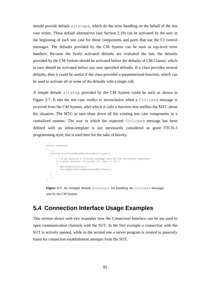
81
should provide default altsteps , which do the error handling on the behalf of the test
case writer. These default alternatives (see Section 2.10) can be activated by the user in
the beginning of each test case for those components and ports that use the CI control
messages. The defaults provided by the CM System can be seen as top-level error
handlers. Because the firstly activated defaults are evaluated the last, the defaults
provided by the CM System should be activated before the defaults of CM Classes, which
in turn should be activated before any user specified defaults. If a class provides several
defaults, then it could be useful if the class provided a parameterized function, which can
be used to activate all or some of the defaults with a single call.
A simple default altstep provided by the CM System could be such as shown in
Figure 5-7. It sets the test case verdict to inconclusive when a CiClosed message is
received from the CM System, after which it calls a function that notifies the MTC about
the situation. The MTC in turn shuts down all the existing test case components in a
centralized manner. The way in which the expected CiClosed message has been
defined with an inline-template is not necessarily considered as good TTCN-3
programming style, but is used here for the sake of brevity.
5.4 Connection Interface Usage Examples
This section shows with two examples how the Connection Interface can be are used to
open communication channels with the SUT. In the first example a connection with the
SUT is actively opened, while in the second one a server program is created to passively
listen for connection establishment attempts from the SUT.
module cmSystem { ... altstep d_ciClosedHandler(CiCfgPort p_port) { // If we receive a CiClosed message sent by the CM System Component [] p_port.receive( CiClosed: {?, {sys := ?}} ) { setverdict(inconc); notifyMainTestComponentAndShutDown(); } } ... }
Figure 5-7: An example default altstep() for handling the CiClosed messages
sent by the CM System.
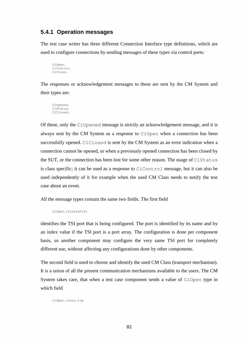
82
5.4.1 Operation messages
The test case writer has three different Connection Interface type definitions, which are
used to configure connections by sending messages of these types via control ports:
CiOpen, CiControl, CiClose.
The responses or acknowledgement messages to these are sent by the CM System and
their types are:
CiOpened, CiStatus, CiClosed.
Of these, only the CiOpened message is strictly an acknowledgement message, and it is
always sent by the CM System as a response to CiOpen when a connection has been
successfully opened. CiClosed is sent by the CM System as an error indication when a
connection cannot be opened, or when a previously opened connection has been closed by
the SUT, or the connection has been lost for some other reason. The usage of CiStatus
is class specific; it can be used as a response to CiControl message, but it can also be
used independently of it for example when the used CM Class needs to notify the test
case about an event.
All the message types contain the same two fields. The first field
ciOpen.tsiDataPort
identifies the TSI port that is being configured. The port is identified by its name and by
an index value if the TSI port is a port array. The configuration is done per component
basis, so another component may configure the very same TSI port for completely
different use, without affecting any configurations done by other components.
The second field is used to choose and identify the used CM Class (transport mechanism).
It is a union of all the present communication mechanisms available to the users. The CM
System takes care, that when a test case component sends a value of CiOpen type in
which field
ciOpen.class.tcp

83
is present, this is automatically routed to the class that is identified by name "tcp ".
Similarly,
ciOpen.class.udp
is routed to the class "udp ". When a test case component receives a message from the
CM System, the union alternative of class field identifies the class that sent the
message. For example, when the tcp alternative is present in the message, it means the
message was sent by the class “tcp ”:
ciOpened.class.tcp.
All the other parameters the user can set depend on the used class. For example, a CM
Class called "tcp " could contain the following parameter fields:
ciOpen.class.tcp.localPort, ciOpen.class.tcp.localIp.ipv4, ciOpen.class.tcp.remotePort, ciOpen.class.tcp.remoteIp.ipv6, ciOpen.class.tcp.options.rxBufferSize.
If a new communication mechanism is implemented, a new alternative is simply added
into the class field of the CI operation messages to make it usable. A new
communication mechanism could be identified as "ethernet ", and when it is added
into the ciOpen.class union, the CM System automatically routes the configuration
messages in which this new alternative is present to the CM Class identified as
"ethernet ".
5.4.2 TCP connection – open request
The test system configuration could be as shown in Figure 5-8: Two different components
want to use the same TSI port “pt_protoX ” to communicate with different SUT end
points. For both of these connections, there will be an own CM, which takes care of
maintaining the connection with the SUT. The CMs encapsulate all the messages received
from the components within TCP-frames and deliver them to the SUT.

84
In this example the test case components are defined as:
type component TestComponent { port CiCfgPort pt_ctrl; port ProtocolX pt_data; }
The used test system interface component is defined as (or is compatible with):
type component TsiComponent { port ProtocolX pt_protoX; port CiCfgPort pt_config; }
When the user wants to establish a TCP connection between local IPv4 address
"127.0.0.1:4242" (which in this case stands for the IP address assigned to one of the
network interfaces of the computer, in which the test case is executed) and IPv6
destination "fe80::20f:20ff:fe73:80", then the required TTCN-3 code for a component to
request the CM System to open the TCP connection could be the following:
... var CiOpen ciOpen; ciOpen.tsiDataPort.name := "pt_protoX" // Refe rs to system port ciOpen.tsiDataPort.index := omit; // Single port , not an array ciOpen.class.tcp.localPort := "4242"; ciOpen.class.tcp.localIp.ipv4 := "127.0.0.1"; ciOpen.class.tcp.remotePort := "80"; ciOpen.class.tcp.remoteIp.ipv6 := "fe80::20f:20f f:fe73"; ciOpen.class.tcp.options.rxBufferSize := 1024; ... map(self:pt_data, system:pt_protoX); map(self:pt_ctrl, system:pt_config); pt_ctrl.send(ciOpen); ...
TSI component CM Class tcp
CMhandlingComponent1
localPort
Component1
pt_data
pt_ctrl
Component2
pt_data
pt_ctrl
CMhandlingComponent2
localPort
pt_protoX
SUT
port
port
pt_config
TCPconnection
Figure 5-8: Class “tcp” example.

85
The code fragment sends a request to the CM System to open via TSI port
“pt_protoX ” a connection using CM Class “tcp ”, with the following class specific
parameters: local and remote port, local and remote IP, and receipt buffer size (which
could be used to set TCP window size, but which in here is just an example parameter).
To avoid the need of filling in all the different parameter fields, the used CM Class could
provide a TTCN-3 module containing parameterised templates for different purposes,
with default values for seldom used parameters.
5.4.3 TCP connection – opened confirmation
Before a component can start to send or receive data via a connection, whose
configuration it has started by sending the CiOpen message, the component is required
to receive a CiOpened message to confirm that the connection is ready to be used. The
component may send concurrently another CiOpen message for another connection that
should be opened before receiving an acknowledgement to the first one. Similarly to
CiOpen message, its positive and negative acknowledgement messages CiOpened and
CiClosed contain the fields .tsiDataPort and .class :
ciOpened.tsiDataPort ciOpened.class.tcp ciClosed.tsiDataPort ciClosed.class.tcp
The class specific parameters do not have to be the same as in CiOpen , because a class
does not necessarily need to or want to echo back to component the same parameter
values the component sent to it. The parameters of CiOpened message could contain for
example status information and identifiers that can be used in further communication. The
parameters of CiClosed message could contain an error code, which explains why the
connection could not be opened to help in solving the problem.
Going back to the "tcp "-class example, the TTCN-3 code for the receipt could be the
following: First, it is checked that the response is to the right CiOpen message by
checking that the port identifier and the present class are correct in the received message
(i.e. the same as in the sent ciOpen message). If the connection was successfully
opened, the positive acknowledgement ciOpen is received from the CM that handles the
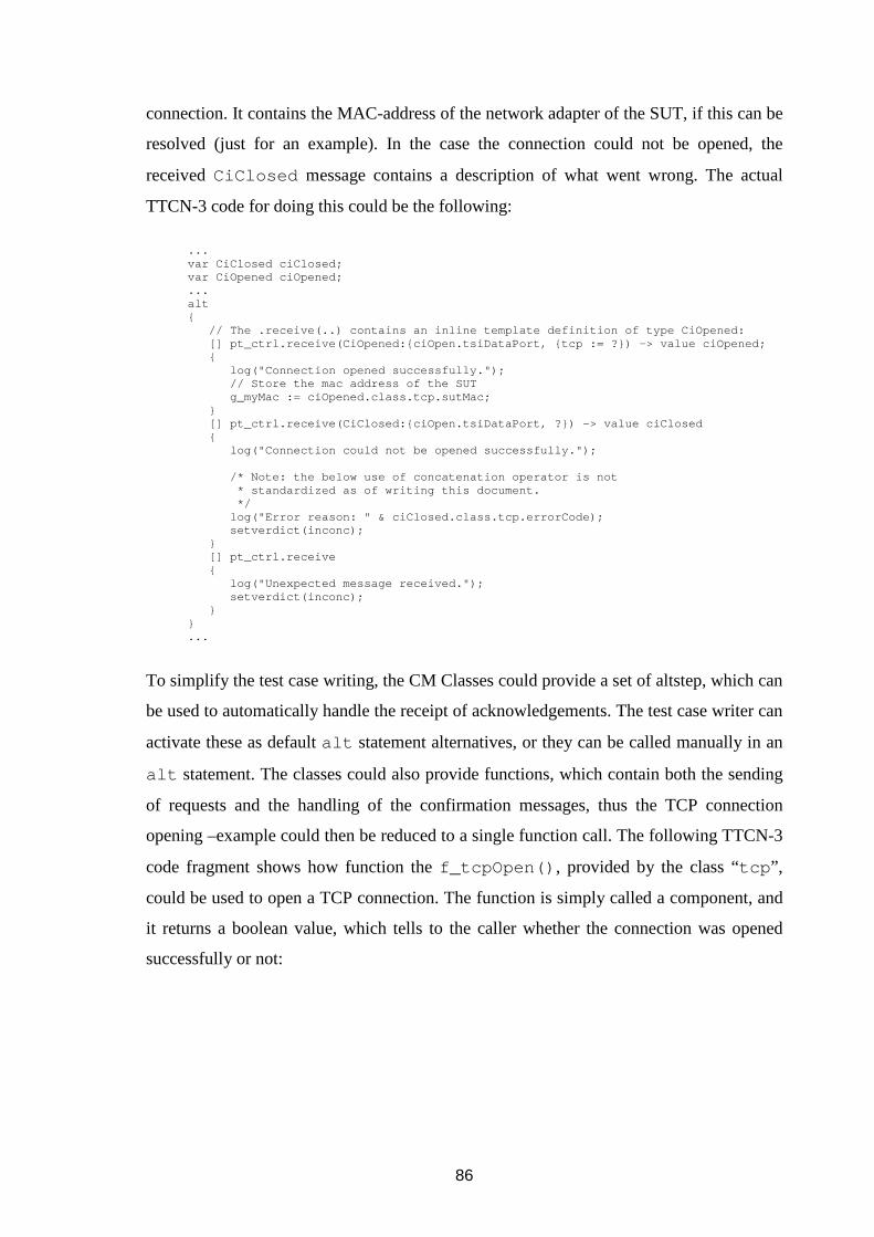
86
connection. It contains the MAC-address of the network adapter of the SUT, if this can be
resolved (just for an example). In the case the connection could not be opened, the
received CiClosed message contains a description of what went wrong. The actual
TTCN-3 code for doing this could be the following:
... var CiClosed ciClosed; var CiOpened ciOpened; ... alt { // The .receive(..) contains an inline template definition of type CiOpened: [] pt_ctrl.receive(CiOpened:{ciOpen.tsiDataPort, {tcp := ?}) -> value ciOpened; { log("Connection opened successfully."); // Store the mac address of the SUT g_myMac := ciOpened.class.tcp.sutMac; } [] pt_ctrl.receive(CiClosed:{ciOpen.tsiDataPort, ?}) -> value ciClosed { log("Connection could not be opened successfu lly."); /* Note: the below use of concatenation opera tor is not * standardized as of writing this document. */ log("Error reason: " & ciClosed.class.tcp.err orCode); setverdict(inconc); } [] pt_ctrl.receive { log("Unexpected message received."); setverdict(inconc); } } ...
To simplify the test case writing, the CM Classes could provide a set of altstep, which can
be used to automatically handle the receipt of acknowledgements. The test case writer can
activate these as default alt statement alternatives, or they can be called manually in an
alt statement. The classes could also provide functions, which contain both the sending
of requests and the handling of the confirmation messages, thus the TCP connection
opening –example could then be reduced to a single function call. The following TTCN-3
code fragment shows how function the f_tcpOpen() , provided by the class “tcp ”,
could be used to open a TCP connection. The function is simply called a component, and
it returns a boolean value, which tells to the caller whether the connection was opened
successfully or not:
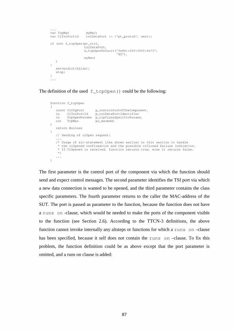
87
... var TcpMac myMac; var CiTsiPortId tsiDataPort := {"pt_protoX", omi t}; if (not f_tcpOpen(pt_ctrl, tsiDataPort, a_tcpOpenDefault("fe80::20f:20ff: fe73", "80"), myMac) ) { setverdict(false); stop; } ...
The definition of the used f_tcpOpen() could be the following:
function f_tcpOpen ( inout CiCfgPort p_controlPortOfTheComponent , in CiTsiPortId p_tsiDataPortIdentifier in TcpOpenParams p_tcpClassSpecificParams, out TcpMac po_macAddr ) return Boolean { // Sending of ciOpen request: ... /* Usage of alt-statement like shown earlier in this section to handle * the ciOpened confirmation and the possible ci Closed failure indication. * If CiOpened is received, function returns tru e, else it returns false. */ ... }
The first parameter is the control port of the component via which the function should
send and expect control messages. The second parameter identifies the TSI port via which
a new data connection is wanted to be opened, and the third parameter contains the class
specific parameters. The fourth parameter returns to the caller the MAC-address of the
SUT. The port is passed as parameter to the function, because the function does not have
a runs on -clause, which would be needed to make the ports of the component visible
to the function (see Section 2.6). According to the TTCN-3 definitions, the above
function cannot invoke internally any altsteps or functions for which a runs on –clause
has been specified, because it self does not contain the runs on –clause. To fix this
problem, the function definition could be as above except that the port parameter is
omitted, and a runs on clause is added:

88
function f_tcpOpenWithRunsOn ( in CiTsiPortId p_tsiDataPortIdentifier in TcpOpenParams p_tcpClassSpecificParams, out TcpMac po_macAddr ) runs on CiControl return Boolean { ... }
The definition of the component type CiControl on which the function
f_tcpOpenWithRunsOn is specified to run could be defined as:
type component CiControl { CiCfgPort pt_ctrl }
This definition of CiControl is runs on –compatible with the definition of
TestComponent :
type component TestComponent { port CiCfgPort pt_ctrl; port ProtocolX pt_data; }
This means that f_tcpOpenWithRunsOn can be called from a component of type
TestComponent , and f_tcpOpenWithRunsOn has an access to the CiCfgPort
ctrl -port, without the need to provide it as one of the function parameters. This is
useful, because when the functions the class “tcp ” are designed, it is not known in which
kind of component types want to use the services provided by the class. Because of this,
all the functions and altsteps the class provides could be defined to be run on components
of the type CiControl . As long as the client test case components are runs on –
compatible with the CiControl , they can call the functions provided by the class.
5.4.4 TCP connection – data
Once the component has received the ciOpened confirmation message from the CM
System, it can start using the opened data connection. For example, when the SUT is
assumed to be a web-server and HTTP GET method is used to request web page via the
opened TCP connection, the TTCN-3 code could be something like the following:
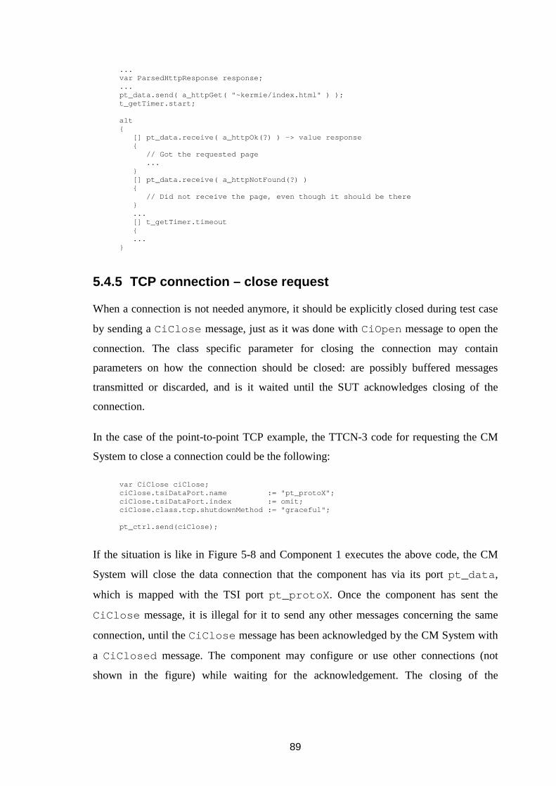
89
... var ParsedHttpResponse response; ... pt_data.send( a_httpGet( "~kermie/index.html" ) ); t_getTimer.start; alt { [] pt_data.receive( a_httpOk(?) ) -> value respo nse { // Got the requested page ... } [] pt_data.receive( a_httpNotFound(?) ) { // Did not receive the page, even though it s hould be there } ... [] t_getTimer.timeout { ... }
5.4.5 TCP connection – close request
When a connection is not needed anymore, it should be explicitly closed during test case
by sending a CiClose message, just as it was done with CiOpen message to open the
connection. The class specific parameter for closing the connection may contain
parameters on how the connection should be closed: are possibly buffered messages
transmitted or discarded, and is it waited until the SUT acknowledges closing of the
connection.
In the case of the point-to-point TCP example, the TTCN-3 code for requesting the CM
System to close a connection could be the following:
var CiClose ciClose; ciClose.tsiDataPort.name := "pt_protoX"; ciClose.tsiDataPort.index := omit; ciClose.class.tcp.shutdownMethod := "graceful"; pt_ctrl.send(ciClose);
If the situation is like in Figure 5-8 and Component 1 executes the above code, the CM
System will close the data connection that the component has via its port pt_data ,
which is mapped with the TSI port pt_protoX . Once the component has sent the
CiClose message, it is illegal for it to send any other messages concerning the same
connection, until the CiClose message has been acknowledged by the CM System with
a CiClosed message. The component may configure or use other connections (not
shown in the figure) while waiting for the acknowledgement. The closing of the

90
connection done by Component 1 has no effect on the connection that Component 2 has
via the same TSI port, because every component that exists during a test case may
configure any of the TSI ports independently from each other.
5.4.6 TCP connection – closed confirmation and indi cation
Similarly as CiOpened message is used to acknowledge the CiOpen message, the CM
System uses CiClosed message to acknowledge the CiClose message. CiClosed
message is also used as a negative acknowledgement to CiOpen , when opening of a new
connection fails for some reason, and as an indication, when a previously opened
connection has been closed. Because of this, a well-written test case has to be ready to
accept the CiClosed messages at any time via its control port. The non-requested or
unexpected closing indications can be handled by activating a class provided default
altstep in the beginning of the testcase or a function, like is done in the below code:
testcase tc_example() runs on TestComponent system TsiComponent { ... /* pt_ctrl is port reference this components con trol port, * {"pt_protoX", omit} is a value of type CiTsiP ortId */ activate(def_tcpClosedInd(pt_ctrl, {"pt_protoX", omit})); ...
The def_tcpClosedInd is an altstep, which takes a reference to the control port of
the component as the first parameter, and identifier of the TSI port as the second
parameter, to be able to know which component port is used for the CI control messages,
and which data connection is in question.
A confirmation to the CiClose message could be handled with a class provided altstep,
or manually like in the below TTCN-3 code fragment. The receive statement re-uses
the TSI port name from the sent ciOpen message (ciOpen.tsiDataPort ):
var CiClosed ciClosed; pt_ctrl.receive(CiClosed:{ciOpen.tsiDataPort, {tcp := ?}) -> value ciClosed; /* The below log statement call is not standardized , but * an example of how one might return statistics da ta within the * ciClosed message, and have them printed into the log file. */ log("Connection closed successfully. Statistics of the connection:"); log(ciClosed.class.tcp.connStats);
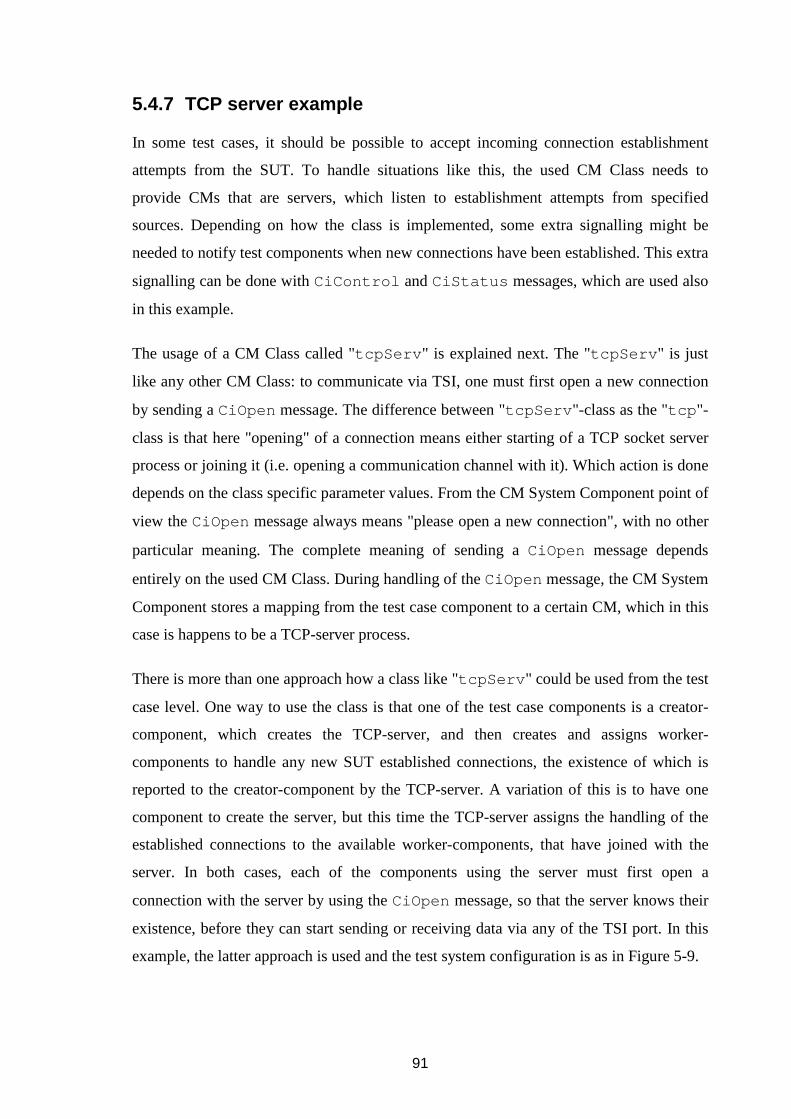
91
5.4.7 TCP server example
In some test cases, it should be possible to accept incoming connection establishment
attempts from the SUT. To handle situations like this, the used CM Class needs to
provide CMs that are servers, which listen to establishment attempts from specified
sources. Depending on how the class is implemented, some extra signalling might be
needed to notify test components when new connections have been established. This extra
signalling can be done with CiControl and CiStatus messages, which are used also
in this example.
The usage of a CM Class called "tcpServ " is explained next. The "tcpServ " is just
like any other CM Class: to communicate via TSI, one must first open a new connection
by sending a CiOpen message. The difference between "tcpServ "-class as the "tcp "-
class is that here "opening" of a connection means either starting of a TCP socket server
process or joining it (i.e. opening a communication channel with it). Which action is done
depends on the class specific parameter values. From the CM System Component point of
view the CiOpen message always means "please open a new connection", with no other
particular meaning. The complete meaning of sending a CiOpen message depends
entirely on the used CM Class. During handling of the CiOpen message, the CM System
Component stores a mapping from the test case component to a certain CM, which in this
case is happens to be a TCP-server process.
There is more than one approach how a class like "tcpServ " could be used from the test
case level. One way to use the class is that one of the test case components is a creator-
component, which creates the TCP-server, and then creates and assigns worker-
components to handle any new SUT established connections, the existence of which is
reported to the creator-component by the TCP-server. A variation of this is to have one
component to create the server, but this time the TCP-server assigns the handling of the
established connections to the available worker-components, that have joined with the
server. In both cases, each of the components using the server must first open a
connection with the server by using the CiOpen message, so that the server knows their
existence, before they can start sending or receiving data via any of the TSI port. In this
example, the latter approach is used and the test system configuration is as in Figure 5-9.

92
The server creator component is responsible for starting up the CM entity called
“myServ”, which acts as a TCP socket server. After this, the worker components may join
with the server to make themselves known to it. The server notifies free worker
components about any new connections the SUT opens with the server. A worker
component can reply to the server whether it is willing to handle a particular connection
or should the connection be closed by the server. Each of the worker components is
mapped with the same TSI port “pt_protoX ”, but they each communicate with
different SUT address via the server.
The test case components need a way to identify the used server if the CM Class is such
that it supports several differently configured servers simultaneously. The server
identifier could be given to the server by the component that creates it, or it could be
given by the CM Class of the server. If the identifier is given by the CM Class, it can be
made known to the test case components as one of the return values of the CiOpened -
message that acknowledges the server creation. In this example this is done the other way
round. The creator-component decides the identifier for the server, so the class specific
part of the CiOpen message contains the server identifier as one of its fields. It also
passes this identifier to all the worker-components it creates.
The following TTCN-3 type definitions are used to start up the server and to join it:
TSI component
Server creator component pt_ctrl
Worker component
data
ctrl
Worker component
data
ctrl
Worker component
pt_data
pt_ctrl
pt_config
p_protoX
CM Class tcpServ
CM”myServ” listenPort
SUT
port
port
port
From component:ciOpen.class.tcpServ.srvStartciClose.class.tcpServ.srvStop
From components:ciOpen.class.tcpServ.srvJoinciClose.class.tcpServ.srvPartciControl.class.tcpServ.conn.acceptciControl.class.tcpServ.conn.rejectciControl.class.tcpServ.conn.close
To component:ciOpened.class.tcpServciClosed.class.tcpServ
To components:ciStatus.class.tcpServ.conn.new
Figure 5-9: Class “tcpServ” example.
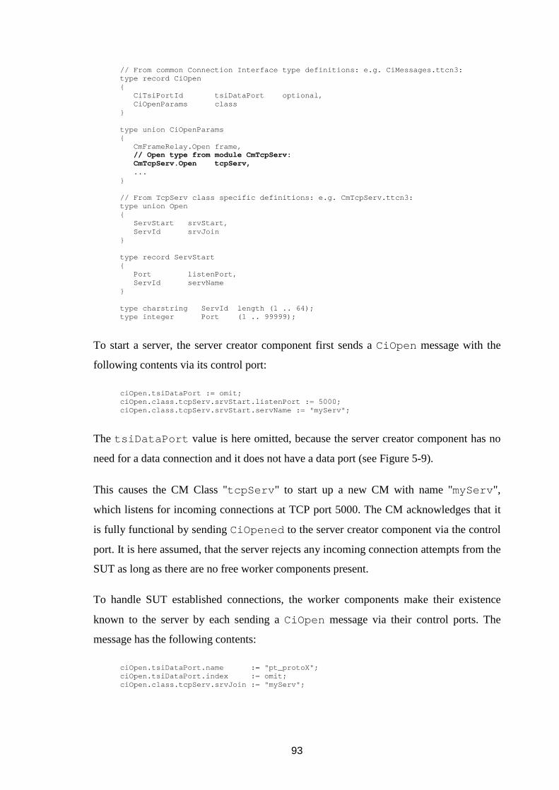
93
// From common Connection Interface type definition s: e.g. CiMessages.ttcn3: type record CiOpen { CiTsiPortId tsiDataPort optional, CiOpenParams class } type union CiOpenParams { CmFrameRelay.Open frame, // Open type from module CmTcpServ: CmTcpServ.Open tcpServ, ... } // From TcpServ class specific definitions: e.g. Cm TcpServ.ttcn3: type union Open { ServStart srvStart, ServId srvJoin } type record ServStart { Port listenPort, ServId servName } type charstring ServId length (1 .. 64); type integer Port (1 .. 99999);
To start a server, the server creator component first sends a CiOpen message with the
following contents via its control port:
ciOpen.tsiDataPort := omit; ciOpen.class.tcpServ.srvStart.listenPort := 5000; ciOpen.class.tcpServ.srvStart.servName := "myServ";
The tsiDataPort value is here omitted, because the server creator component has no
need for a data connection and it does not have a data port (see Figure 5-9).
This causes the CM Class "tcpServ " to start up a new CM with name "myServ ",
which listens for incoming connections at TCP port 5000. The CM acknowledges that it
is fully functional by sending CiOpened to the server creator component via the control
port. It is here assumed, that the server rejects any incoming connection attempts from the
SUT as long as there are no free worker components present.
To handle SUT established connections, the worker components make their existence
known to the server by each sending a CiOpen message via their control ports. The
message has the following contents:
ciOpen.tsiDataPort.name := "pt_protoX"; ciOpen.tsiDataPort.index := omit; ciOpen.class.tcpServ.srvJoin := "myServ";

94
The CM System Component knows from the tsiDataPort value via which TSI port a
component wants to open a data connection (with the server). The CM Class "tcpServ "
knows from the server identifier "myServ ", that a component wants to use this
previously created server. The CM "tcpServ " acknowledges to each of the worker
components with a CiOpened , that the component is now connected with the server.
When the SUT establishes a connection with the server, the server notifies one of the
joined components about this with a CiStatus message, which contains the IP- and
port-address of the SUT. The component then decides whether it accepts the connection,
and sends its conclusion to the server in a CiControl message. If the component
accepted the connection, the server starts to forward any data received from the specific
SUT address to the worker component via the chosen data port, and the other way round.
In the case the component decided to reject the connection, the server closes the TCP-
socket. The below code fragment shows the type definition of the CiControlParams
union used in the CiControl message, and the class specific types Control and
ServConn :
// From common Connection Interface type definition s, e.g. CiMessages.ttcn3: type record CiControl { CiTsiPortId tsiDataPort optional, CiControlParams class } type union CiControlParams { ... // Control type from module CmTcpServ: CmTcpServ.Control tcpServ, ... } // From TcpServ class specific definitions, e.g. Cm TcpServ.ttcn3: type record Control { ServId server, ServConn conn } type union ServConn { IpAddrAndPort accept, // This alternative accep ts a connection IpAddrAndPort reject, // This rejects IpAddrAndPort close // This closes }
When a worker component wants to close a connection assigned to it, it send a
CiControl message with "close" instruction to the server. When a component wants to

95
"part" the server, as opposed to joining it, or when it wants to shut down the server, it
sends an appropriate CiClose message to the server. The CiClosed message contains
a class specific part like in CiOpen and CiControl , with which the desired action is
chosen:
// From common Connection Interface type definition s, e.g. CiMessages.ttcn3: type union CiCloseParams { ... // Control type from module CmTcpServ: CmTcpServ.Close tcpServ, ... } // Used in union CiCloseParams. type union Close { ServId srvPart, // This alternative parts from a server ServId srvClose // This alternative close s a server }
5.5 Overview of CM System Interface
The CM System Interface (CSI) is used by the SA to use the services provided by the CM
System (Component). There are three categories of operations at the CM System
Interface: system, class, and connection. With the system level operations the SA can
initialize and shutdown the whole CM System. The class level operations are used by the
SA to register the used CM Classes into the system. In registration of a class the SA
passes an interface object or method to the CM System. This interface object is used by
the CM System Component to call classes’ implementations of the CM Class Interface
operations, which are explained in the next section. Once the registration is completed,
the SA can instruct the CM System Component to call the class specific initialization
function of each class. During test case execution, the SA uses the connection level
operations to forward the TRI operations resulting from Connection Interface operations
to the CM System to be handled.
The connection level operations are listed in Table 5-5. When a test case component
wants to open a new connection by using the ciOpen() operation (5.2.4, 5.4.2), this is
seen by the SA as the triSend() operation at the TRI interface. Because the SA does
not know which TSI ports are control ports, it does not know whether the
sendMessage parameter of the triSend() contains a control message or user data.

96
The CM System Component provides operation csiConnDecodeOp() to the SA,
which identifies the message for the SA and tells it what CSI interface operation it should
call to handle the message. If the message was received via a TSI control port, then it is
assumed to contain a control message, such as the ciOpen message encoded in the
format of CmSysControlMessage (specified in Table 5-3). In this case the
csiConnDecodeOp() also decodes the message. If it was received via a TSI data port,
then it contains user data and no decoding is done. Because in this example the
sendMessage does contain the ciOpen message, the csiConnDecodeOp()
decodes it and instructs the SA to call the csiConnOpen() with the decoded values.
After this the SA has done everything needed. All the triSend() invocations are
handled in this way.
In the case of procedure-based operation (such as call ), the SA calls directly the right
CSI operation (csiConnCall() , csiConnReply() , csiConnRaise()) without
first consulting the decode operation, because the procedure-based communication can
contain only user data.
The operations and data types of the CM System Interface are specified in detail in
Appendix A.1
Table 5-5: Connection operations of CM System Interface.
Category: Call Direction: Operation Identifier:
SA � CM System Comp.
SA � CM System Comp.
SA � CM System Comp.
SA � CM System Comp.
SA � CM System Comp.
SA � CM System Comp.
SA � CM System Comp.
SA � CM System Comp.
csiConnDecodeOp:
csiConnOpen
csiConnControl
csiConnClose
csiConnSend
csiConnCall
csiConnReply
csiConnRaise
Connection
SA � CM System Comp. csiConnTerminate
97
5.6 Overview of CM Class Interface
The CM Class Interface is the interface between the CM System Component and the CM
Classes. The operations consist of class and connection level operations, and of an
encoding operation. With the class level operations the CM System Component can
initialize the CM Classes before they are used. The connection level operations provided
by the CM Classes correspond with the connection level operations of the CSI interface
(previous section), and they are cciConnOpen() , cciConnControl() , cciConn-
Close() , cciConnData() , and cciConnTerminate() . The cciConnData
operation groups together all the non-configuration operations (csiConnSend() ,
csiConnCall() , csiConnReply() , csiConnRaise() ). All these CM Class
Interface operations are implemented by the CM Classes in a class specific manner.
The CM System Component provides operations cciConnClosed() and
cciEncodeCiCtrlOp() to the CM Classes. The operation cciConnClosed() is
used by the CM Class or its CMs to indicate to the CM System Component when a
connection is closed without the CM System Component requesting for it, so that it
knows to update its controlMap and handlerMap data structures accordingly. When
a CM wants to send a Connection Interface level message (CiOpened , CiClosed ,
CiStatus ) to the test case component, it can use cciEncodeCiCtrlOp() to do the
encoding of the CI control message into CmSysControlMessage format ( Table 5-
3). Thus, the CM Classes and their CMs do not need to known the transfer syntax of the
Connection Interface control messages, except for their own class specific parameter part.
The operations and data types of the CM Class Interface are specified in detail in
Appendix A.2.
5.7 Overview of Mapping Interface
Mapping Interface (MI) is a small interface between the CMs and the SA, and all the
operations are provided by the SA. With these operations the CM can lock and release a
test case component identifier and a TSI port identifier stored in the SA’s tsiMap data
structure for a small duration of time, when it is about to enqueue a message or procedure

98
operation to the test case component by using a TRI interface triEnqueue*()
operation. The CM uses csiConnId (explained in 4.3.2, 4.3.3) as the key to query for a
(component identifier, TSI port identifier)–pair. If no pair matching with the
csiConnId can be found, the CM knows from this that the component has unmapped
its port from the TSI port, and it does not try to communicate with it. When a (component
identifier, TSI port identifier)–pair is found, it becomes locked for the CM. If the SA tries
to call the triUnmap() operation while a pair is locked, it becomes blocked in
invocation of the operation (see section 3.3) until the pair is released by the CM. This is
needed to avoid the situation in which a CM might call a TRI operation with invalid out-
of-date values. The TTCN-3 standard does not specify what is the result of using out-of-
date values, hence this interface is used to avoid any undesirable effects on the test case
verdict and to make the system more portable between different TTCN-3 tools of
different vendors.
This interface specifies only the lock and release operations used by the CM, and they can
be found in Appendix A.3. In addition to these, the SA has to implement its tsiMap data
structure and triUnmap() operation in such a way that they take the locking into
account.
99
6 CONCLUSIONS In the first part of this thesis work an overview of the TTCN-3 Core Langue was given
and it was explained what kind of entities and standardized interfaces exist in TTCN-3
test system. In the second part it was shown how one could design on the top of the
TTCN-3 standard such a connection management system, that provides simultaneously
several kinds of the connection means with the SUT. These different connection means
can be used in a uniform way from TTCN-3 test cases, and when new means are
developed, these can be easily added into the system without breaking the existing
TTCN-3 source or SUT Adapter code.
When designing new CM Classes one needs to consider how the connection management
related parameters are seen at the test case level by the user. Are they made easy to be
encoded into to a transfer syntax form, or are they designed easy to be used by the user
and perhaps bit harder to be encoded. Some thought needs to be put on how codecs can be
taken into use in the chosen TTCN-3 tool, and how they are designed and implemented.
This is needed to avoid situations in which addition of a new field to a type, or changing a
type identifier breaks an existing codec. Designing a generic codec by using the interfaces
provided by the standard can be difficult, thus in this work an idea of a CM Class Codec
System was introduced. It helps in adding new classes into the system without breaking
the codecs of the Connection Interface messages (CiOpen , CiOpened , and so on), by
giving the codecs of these types an access to the class specific codecs.
What was not considered in this work are the exact language mappings (such as for C or
Java) of the CM System Interface, the CM Class Interface, and the Mapping Interface.
The types used in the interfaces probably need own functions with which they can be
operated. For example, there could be a function or a method that generates a
csiConnId identifier from the component and port identifiers that are received as the
parameters of the triSend() operation. When designing language mappings of the
interfaces, one needs to consider how parameters are passed over the interfaces. In the
given abstract interface specifications all the values are assumed to be passed safely by
copying. In a real implementation this pass-by-copy would be inefficient. Based on the

100
experience gained on the prototype code that was written during this thesis work, one
should be able to rather easily specify the interfaces in a way that avoids excess copying.
A topic that was not considered in the text is how the used TTCN-3 types should be
grouped into modules, and what kind of TTCN-3 types, templates, functions and altsteps
the modules of the different CM Classes should provide. The definitions related to a CM
Class could be stored into an own module, but this class specific module could be divided
even further: the (public) definitions required to use the services provided by the class
could be stored into one module, and the (private) definitions that are used by the class
internally could be stored into another module. TTCN-3 Core Language contains also a
language element called group , which can be used to group definitions within a single
module. It could be used if it turns out that it is more feasible to keep the definitions in a
single module, instead of having a public and a private module. A common naming
convention used in the modules of the different CM Classes might worth be considering.
If the “top level” error handling altstep provided by every class were titled as
“alt_errorTop” , then the user would directly know which altstep to use.
The test case writer can open connections by using the Connection Interface operations
directly. Instead of having to write the operation parameters and the port statements each
time by hand, it could be required that every CM Class provides a set of functions and
default altsteps for doing this on the behalf of the test case writer. Some functions and
altsteps could be mandatory for every class (such as the ones for error handling) and they
could use similar parameters differing only in their type but not in their meaning. Another
useful feature would be to have some kind of centralized error handling that could be
started in one of the test case components. It would take care of instructing all the test
case components to close their connection, when there is a problem with one of the
connections. If this kind of centralized error handling was designed, it should work over
the CM Class boundaries by being able to shutdown connections of any kind.
In the text the Connection Managers were presented as entities, that maintain connections
with the SUT. However, nothing prevents the Connection Managers to provide services
other than connections with the SUT. They could be data generators, traffic generators,
databases, script language interpreters, or any other kind of services that might be utilized

101
during a test case. Usage of the Connection Interface operations in their case would mean
establishing connections with these service providers.
As it was mentioned in the Introduction, as of writing this thesis work there is not much
literature or other material available on TTCN-3 and SUT Adapter design. This thesis
raised issues that need to be considered in the adapter design, and it specified a
framework, which supports several kinds of connection means with the SUT. The
framework should prove very useful over time when new kinds of targets are needed to
be tested. If a framework like the one presented or one with similar capabilities was
widely used and its interfaces were made public, then different companies and
communities could participate in the development of free and commercial Connection
Manager plug-ins. One could then expand the capabilities of an own test system with
these plug-ins without the fear of losing any already existing functionality, thus greatly
reducing time and resources spent in making changes to the existing system, before new
kinds of targets can be tested.

102
REFERENCES
[T3CORE] ETSI ES 201 873-1 V2.2.1 Methods for Testing and Specification (MTS); The Testing
and Test Control Notation version 3; Part 1: TTCN-3 Core Language. France:
European Telecommunications Standard Institute, 2003. 178 pages.
[T3TFT] ETSI ES 201 873-2 V2.2.1 Methods for Testing and Specification (MTS); The Testing
and Test Control Notation version 3; Part 2: TTCN-3 Tabular presentation Format
(TFT). France: European Telecommunications Standard Institute, 2003. 33 pages.
[T3GFT] ETSI ES 201 873-3 V2.2.2 ETSI Standard Methods for Testing and Specification
(MTS); The Testing and Test Control Notation version 3; Part 3: TTCN-3 Graphical
presentation Format (GFT). France: European Telecommunications Standard Institute,
2003. 165 pages.
[T3OS] ETSI ES 201 873-4 V2.2.1 Methods for Testing and Specification (MTS); The Testing
and Test Control Notation Version 3; Part 4: TTCN-3 Operational Semantics. France:
European Telecommunications Standard Institute, 2003. 138 pages.
[T3TRI] ETSI ES 201 873-5 V1.1.1 Methods for Testing and Specification (MTS); The Testing
and Test Control Notation version 3; Part 5: TTCN-3 Runtime Interface (TRI). France:
European Telecommunications Standard Institute, 2003. 55 pages.
[T3TCI] ETSI ES 201 873-6 V1.1.1 Methods for Testing and Specification (MTS); The Testing
and Test Control Notation version 3; Part 6: TTCN-3 Control Interface (TCI). France:
European Telecommunications Standard Institute, 2003. 106 pages.
[T3MOCKUP] ETSI ES 201 873-1 V3.0.0Mockupv1 Methods for Testing and Specification (MTS);
The Testing and Test Control Notation version 3; Part 1: TTCN-3 Core Language.
France: European Telecommunications Standard Institute, 2004. 190 pages.
[TIMED] Dai, Z. R., Grabowski J., Neukirchen H. Timed TTCN-3 – A Real-Time Extension for
TTCN-3. TestCom 2002: Testing Internet Technologies and Services, The IFIP 14th
International Conference on Testing of Communicating Systems, March 19th - 22nd,
2002, Berlin. Kluwer Academic Publishers, March 2002. pp. 407-424.
[UNIX] Stevens, Richard W. UNIX Network Programming, Volume 1, 2nd edition. Prentice
Hall, 1998. 1009 pages.

103
APPENDICES
A INTERFACES IN DETAIL
A.1 CM System Interface
The CM System Interface is used by the SA to use the services provided by the CM
System. There are three categories of operations at the CM System Interface. The ones
that affect the system as a whole are prefixed with “csi ”. With these, the whole CM
System is initialized before it is taken into use, and finalized when its services are not
needed any more. Similarly, the operations used at connection manager class level have
“csiClass ” prefix. With these operations the classes are registered to the system and
initialized before taken into use. The operations that are used to open, control, and close
connections, and to send data through them, begin with “csiConn ” prefix. All the
operations are procedure calls and they are listed in Table A-1.
Table A-1: Operations at CM System Interface. Decode Port Operation is used to
identify the connection related operations that are listed below it.
Category: Call Direction: Operation Identifier:
System SA � CM System Comp.
SA � CM System Comp.
SA � CM System Comp.
csiInit
csiFinalize
csiReset
Class SA � CM System Comp.
SA � CM System Comp.
SA � CM System Comp.
SA � CM System Comp.
csiClassReg
csiClassDeReg
csiClassInit
csiClassFinalize
SA � CM System Comp.
SA � CM System Comp.
SA � CM System Comp.
SA � CM System Comp.
SA � CM System Comp.
SA � CM System Comp.
SA � CM System Comp.
SA � CM System Comp.
csiConnDecodeOp
csiConnOpen
csiConnControl
csiConnClose
csiConnSend
csiConnCall
csiConnReply
csiConnRaise
Connection
SA � CM System Comp. csiConnTerminate

104
A.1.1 Data types
The following abstract data types are used with the CM System Interface operations.
Table A-2: Data types at CM System Interface.
Type Identifier: Description:
CsiCharacterType This type can hold a single character value.
CsiCiOpIdType Each of the Connection Interface operations has a unique identifier at SA
and CM System implementation language level. This enumerated type
provides identifiers for the operations: csiCiOpenId , csiCiOpenedId ,
csiCiControlId , csiCiStatusId , csiCiCloseId ,
csiCiClosedId , csiCiDataId , and csiCiDataIndId .
NOTE: When a component sends a CI control category message (5.2
Connection Interface), the CM System Component uses csiCiOpenId ,
csiCiControlId , and csiCiCloseId values to determine which
operation is in question (A.1.2 Operations: csiConnDecodeOp() ). When
a CM or CM Class wants to build a CI control category message with the
CM System Component provided operation cciEncodeCiCtrlOp()
(A.2.2 Operations), the values csiCiOpenedId , csiCiStatusId , and
csiCiClosedId are used to determine which message should be built.
The values csiCiDataId and csiCiDataIndId are not used in this
document.
NOTE 2: This type is of fixed length.
CsiClassDataType A value of this type contains CM Class specific configuration data of a
Connection Interface operation encoded in a class specific form. It contains a
length field, and the data field. The CM Class does the encoding and
decoding of the data, thus its contents are not visible to the CM System
Component.
CsiClassIfaceType A value of this type contains a method for accessing the CM Class Interface
operations of a class (see Table A-4). Depending on implementation
language, the method can be a function pointer array of the class operations,
or it can be an interface object that provides the class operations as its
methods.
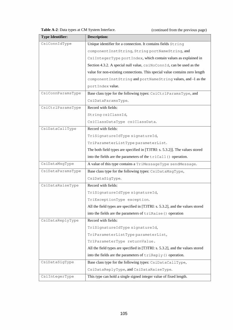
105
Table A-2: Data types at CM System Interface.
Type Identifier: Description:
CsiConnIdType Unique identifier for a connection. It contains fields String
componentInstString , String portNameString , and
CsiIntegerType portIndex , which contain values as explained in
Section 4.3.2. A special null value, csiNoConnId , can be used as the
value for non-existing connections. This special value contains zero length
componentInstString and portNameString values, and -1 as the
portIndex value.
CsiConnParamsType Base class type for the following types: CsiCtrlParamsType , and
CsiDataParamsType .
CsiCtrlParamsType Record with fields:
String csiClassId ,
CsiClassDataType csiClassData .
CsiDataCallType Record with fields:
TriSignatureIdType signatureId ,
TriParameterListType parameterList .
The both field types are specified in [T3TRI: s. 5.3.2]]. The values stored
into the fields are the parameters of the triCall() operation.
CsiDataMsgType A value of this type contains a TriMessageType sendMessage .
CsiDataParamsType Base class type for the following types: CsiDataMsgType ,
CsiDataSigType .
CsiDataRaiseType Record with fields:
TriSignatureIdType signatureId ,
TriExceptionType exception .
All the field types are specified in [T3TRI: s. 5.3.2], and the values stored
into the fields are the parameters of triRaise() operation
CsiDataReplyType Record with fields:
TriSignatureIdType signatureId ,
TriParameterListType parameterList ,
TriParameterType returnValue.
All the field types are specified in [T3TRI: s. 5.3.2], and the values stored
into the fields are the parameters of triReply() operation.
CsiDataSigType Base class type for the following types: CsiDataCallType ,
CsiDataReplyType , and CsiDataRaiseType .
CsiIntegerType This type can hold a single signed integer value of fixed length.
(continued from the previous page)

106
Table A-2: Data types at CM System Interface.
Type Identifier: Description:
CsiOpIdType Each of the test case component initiated Connection Interface operations
has a corresponding CM System Interface operation. Each of these CSI
operations has unique identifier, which can one of the following:
csiConnOpenId , csiConnCloseId , csiConnControlId ,
csiConnSendId , csiConnCallId , csiConnReplyId , and
csiConnRaiseId .
Of these, the csiConnSendId , csiConnCallId ,
csiConnReplyId , and csiConnRaiseId , are used with the
cciConnData() operation to identify which particular operation is in
question.
CsiPortIdListType A list of values of type CsiPortIdType .
CsiPortIdType Record containing port name and port index fields of the
TriPortIdType .
CsiStatusType This type has two values: CSI_OK, and CSI_ERR. The CSI_OK value is
returned by the CSI operations, when the operation call was successful.
CSI_ERR is returned otherwise. In the case of CSI_ERR, the effect of the
operation call is the same as if it was never called.
String This type can hold a sequence of character values. When the implementation
language is C, char* can be used. In the case of Java,
java.lang.String can be used.
TriAddressType Type defined in TTCN-3 Runtime Interface standard [T3TRI: s. 5.3.2]. A
value of this type addresses an entity within the SUT. Its TTCN-3 Core
Language counterpart is the type address .
TriComponentIdType Type defined in TTCN-3 Runtime Interface standard [T3TRI: s. 5.3.1]. A
value of this type identifies a test case component.
TriPortIdListType Type defined in TTCN-3 Runtime Interface standard [T3TRI: s. 5.3.1]. A
value of this type contains a list of values of type TriPortIdType .
TriPortIdType Type defined in TTCN-3 Runtime Interface standard [T3TRI: s. 5.3.1]. A
value of this type identifies either a TSI port or a component port, depending
on the TRI operation in which it is used.
(continued from the previous page)

107
A.1.2 Operations
The following procedure operations are specified at the CM System Interface.
csiInit (SA ���� CM System Component)
In: CsiPortIdListType controlPorts
List of the TSI ports that are used as the control ports by default. There has to
be at least one.
Return: CsiStatusType csiStatus
Status code of the operation call.
Purpose: This operation is used by the SA to initialize the CM System. During the
initialization, the CM System Component may initialize its internal data
structures and do memory allocations if required. As a parameter of this
operation the CM System Component receives a list of the ports that are used
as control ports. After the initialization, the CM System Component is ready
to accept csiClassReg() operation calls.
When: A) At the start-up procedures of the test executable. How the initialization
operation is called depends on the tool that produces the test executables from
the TTCN-3 modules.
B) This operation can be called tool-independently during triExecute-
TestCase() operation, but the CM System Component is possibly
unnecessarily initialized at the beginning of every test case.
C) At the control part of a TTCN-3 module this can be called with TTCN-3
external function call or action statements, before any test cases are executed.
This is seen by the SA as triAction() or triExternalFunction-
Call() operation, from which this operation can be called. Because the
control part of a TTCN-3 module is optional, and the TCI Test Management
interface [T3TCI: s. 7.3.1] allows starting of test cases directly without

108
executing the control part, it possible that the initialization is mistakenly
excluded by the test case executor. This approach is tool independent.
D) Another tool independent approach is to perform this operation during the
first test case of a test suite with an external function call or action statement.
It is also possible to use a special identifier for the test case (such as
tc_initCmSystem ), so the SA knows by it to call this operation.
E) Yet another approach is that the SA is instructed to call this operation in
the preamble part of each test case.
The advantage of the alternatives in which the initialization is started from the
TTCN-3 language level is that the identifiers of the control ports of the used
TSI can be passed down to the CM System; the control ports do not have to
be fixed, they can vary between the test cases or test suites. The drawback is
that the test case user has to remember to do this.
csiFinalize (SA ���� CM System Component)
Purpose: With this operation the SA tells the CM System to shutdown. This consists of
calling the finalization operations of any present connection manager classes
and releasing of any dynamically allocated memory. After this operation no
connections to SUT exist, and no other operations than csiInit() can be
used.
When: A) During finalization procedures of the test executable, if such exist. This
approach is tool dependent.
B) At the control part of a TTCN-3 module, like in the case of initialization.
This approach is tool independent.
C) During triSAReset() operation. Problem with triSAReset() is
that is not visible to TTCN-3 language level. There is no corresponding
TTCN-3 statement, hence it may vary from tool to tool when this operation is
called. This approach is tool dependent.
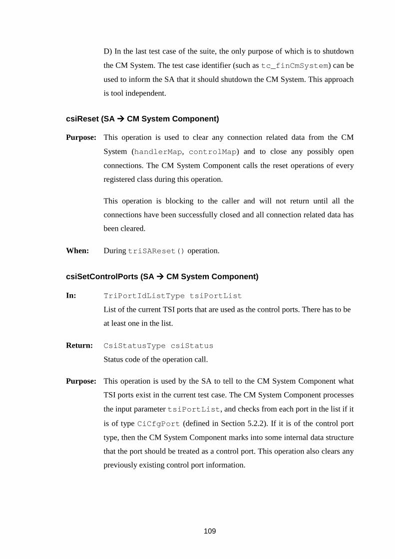
109
D) In the last test case of the suite, the only purpose of which is to shutdown
the CM System. The test case identifier (such as tc_finCmSystem ) can be
used to inform the SA that it should shutdown the CM System. This approach
is tool independent.
csiReset (SA ���� CM System Component)
Purpose: This operation is used to clear any connection related data from the CM
System (handlerMap , controlMap ) and to close any possibly open
connections. The CM System Component calls the reset operations of every
registered class during this operation.
This operation is blocking to the caller and will not return until all the
connections have been successfully closed and all connection related data has
been cleared.
When: During triSAReset() operation.
csiSetControlPorts (SA ���� CM System Component)
In: TriPortIdListType tsiPortList
List of the current TSI ports that are used as the control ports. There has to be
at least one in the list.
Return: CsiStatusType csiStatus
Status code of the operation call.
Purpose: This operation is used by the SA to tell to the CM System Component what
TSI ports exist in the current test case. The CM System Component processes
the input parameter tsiPortList , and checks from each port in the list if it
is of type CiCfgPort (defined in Section 5.2.2). If it is of the control port
type, then the CM System Component marks into some internal data structure
that the port should be treated as a control port. This operation also clears any
previously existing control port information.

110
Note: This operation can possibly be used only in a C implementation. Unlike
the C mapping of the TriPortId type, the Java language mapping does not
provide a method with which one could ask the type identifier of the port.
When: During triExecuteTestCase() , if it is wanted that the TSI control
port(s) can be different in every executed test case.
csiClassReg (SA ���� CM System Component)
In: String csiClassId
Class identifier of the to-be-registered class.
CsiClassIfaceType csiClassIface
Method for the CM System Component to call the class specific operations
described in A.2 CM Class Interface.
Return: CsiStatusType csiStatus
Status code of the operation call.
Purpose: This operation is used to register all the available CM Classes into the CM
System, after which the transmission means provided by them are present in
the system. A class is registered into the system by its name, which is the
same as the field name of the class in Ci<OperationName>Params
union type. The union types are defined in the Connection Interface (Table 5-
2, Figure 5-4). As the result of this operation, the CM System Component can
use csiClassIface to access the CM Class Interface operations of the
registered class.
When: After the csiInit() operation has been performed. The class information
can be stored in a configuration file from which it is passed to the CM System
Component with this operation, or the class information can be hard coded
into the function, which calls this operation.

111
csiClassDeReg (SA ���� CM System Component)
In: String csiClassId
Class identifier of the to-be-removed class.
Purpose: With this operation it is possible to remove class information of a previously
registered CM Class from the CM System, if this is required for some reason.
After this operation the CM System Component has no knowledge on the
removed CM Class, hence the transmission means provide by the removed
class is not available anymore. This operation performs the CM Class
Interface operation cciClassFinalize() to the class.
When: When the class has been first registered into the system with the
csiClassReg() operation.
csiClassInit (SA ���� CM System Component)
Return: CsiStatusType csiStatus
Status code of the operation call.
Purpose: With this operation the CM System Component is instructed to call the class
specific initialization operations of every registered CM Class. After this, the
classes are ready to provide connection managers of their kind.
When: After all the classes have been registered with the csiClassReg()
operation.
csiClassFinalize (SA ���� CM System Component)
Purpose: This operation is opposite to the Class Initialize function. All the resources
reserved by the registered connection manager classes are freed by the system
by calling their class specific finalization operations.
When: This operation is automatically called from the csiFinalize operation.
The SA can also call this explicitly, if the classes are wanted to be finalized
separately from the whole CM System.
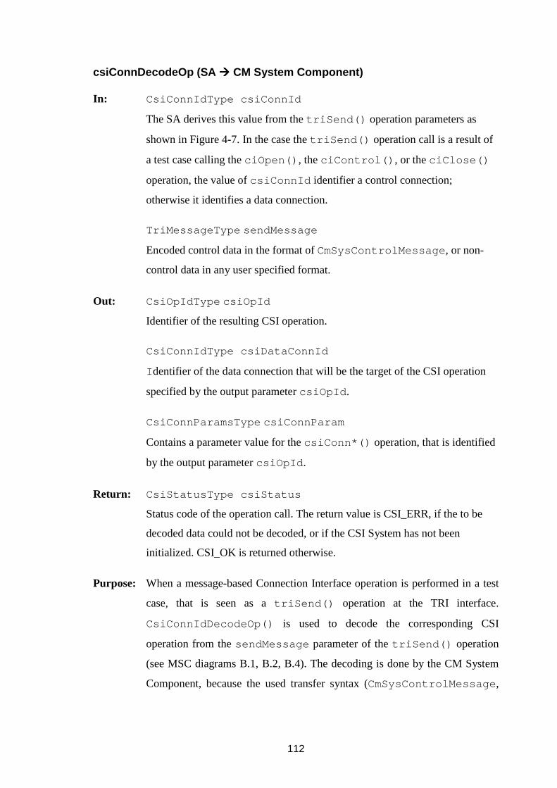
112
csiConnDecodeOp (SA ���� CM System Component)
In: CsiConnIdType csiConnId
The SA derives this value from the triSend() operation parameters as
shown in Figure 4-7. In the case the triSend() operation call is a result of
a test case calling the ciOpen() , the ciControl() , or the ciClose()
operation, the value of csiConnId identifier a control connection;
otherwise it identifies a data connection.
TriMessageType sendMessage
Encoded control data in the format of CmSysControlMessage , or non-
control data in any user specified format.
Out: CsiOpIdType csiOpId
Identifier of the resulting CSI operation.
CsiConnIdType csiDataConnId
I dentifier of the data connection that will be the target of the CSI operation
specified by the output parameter csiOpId .
CsiConnParamsType csiConnParam
Contains a parameter value for the csiConn*() operation, that is identified
by the output parameter csiOpId .
Return: CsiStatusType csiStatus
Status code of the operation call. The return value is CSI_ERR, if the to be
decoded data could not be decoded, or if the CSI System has not been
initialized. CSI_OK is returned otherwise.
Purpose: When a message-based Connection Interface operation is performed in a test
case, that is seen as a triSend() operation at the TRI interface.
CsiConnIdDecodeOp() is used to decode the corresponding CSI
operation from the sendMessage parameter of the triSend() operation
(see MSC diagrams B.1, B.2, B.4). The decoding is done by the CM System
Component, because the used transfer syntax (CmSysControlMessage ,
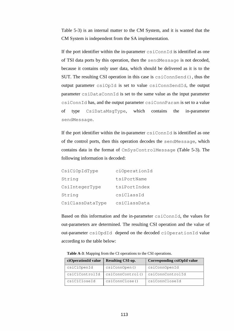
113
Table 5-3) is an internal matter to the CM System, and it is wanted that the
CM System is independent from the SA implementation.
If the port identifier within the in-parameter csiConnId is identified as one
of TSI data ports by this operation, then the sendMessage is not decoded,
because it contains only user data, which should be delivered as it is to the
SUT. The resulting CSI operation in this case is csiConnSend() , thus the
output parameter csiOpId is set to value csiConnSendId , the output
parameter csiDataConnId is set to the same value as the input parameter
csiConnId has, and the output parameter csiConnParam is set to a value
of type CsiDataMsgType , which contains the in-parameter
sendMessage .
If the port identifier within the in-parameter csiConnId is identified as one
of the control ports, then this operation decodes the sendMessage , which
contains data in the format of CmSysControlMessage (Table 5-3). The
following information is decoded:
CsiCiOpIdType ciOperationId
String tsiPortName
CsiIntegerType tsiPortIndex
String csiClassId
CsiClassDataType csiClassData
Based on this information and the in-parameter csiConnId , the values for
out-parameters are determined. The resulting CSI operation and the value of
out-parameter csiOpdId depend on the decoded ciOperationId value
according to the table below:
Table A-3: Mapping from the CI operations to the CSI operations.
ciOperationId value Resulting CSI-op. Corresponding csiOpId value
csiCiOpenId csiConnOpen() csiConnOpenId
csiCiControlId csiConnControl() csiConnControlId
csiCiCloseId csiConnClose() csiConnCloseId

114
For example, if the decoded ciOperationId value is equal to
csiCiOpenId , the out-parameter csiOpdId is set to value
csiConnOpenId , and based on this value the SA knows to call the CSI
operation csiConnOpen() .
The output parameter csiDataConnId is built from the decoded
tsiPortName and tsiPortIndex values, and from the
compInstString field of in-parameter csiConnId ( Figure 4-7 shows
the contents of the CsiConnId type). If this built value equals to the special
value csiNoConnId , then the test case component that sent the
sendMessage did not specify any data port. This means that it wants to
have a control connection without any data connections with the class
specified by the decoded csiClassId value. In any case, the value of the
output parameter csiDataConnId is built it this manner.
The out-parameter CsiConnParamsType csiConnParam is set to
contain the decoded csiClassId and csiClassData stored into a value
of type CsiCtrlParamsType . (CsiConnParamsType is the base type
for the type CsiCtrlParamsType .)
After this operation, the SA knows which CSI operation it should perform
(csiOpId ), what data connection the operation concerns
(csiDataConnId ), and what other parameters the operation has
(csiConnParam ).
When: During triSend() operation, that is executed as a result of a message-
based Connection Interface operation at the TTCN-3 language level. This
operation may not be called from the triCall() , the triReply() , or the
triRaise() operation, because the CM System Interface operations result
from message-based Connection Interface operations only.

115
csiConnOpen (SA ���� CM System Component)
In: CsiConnIdType csiCtrlConnId
Identifier of the control connection that is used for controlling the data
connection, which is identified by the in-parameter csiDataConnId . The
value of the csiCtrlConnId is derived by the SA from the triSend()
operation’s in-parameters tsiPortId and componentId . This is the
same value the SA used as the input parameter csiConnId of
csiConnDecodeOp() .
CsiConnIdType csiDataConnId
Identifier of the data connection that should be opened. This is the same value
that the SA received as the csiDataConnId out-parameter of the
csiConnDecodeOp() operation. In the case a test case component has no
data ports, i.e. it does not want to open a data connection, csiDataConnId
has the special value csiNoConnId .
CsiCtrlParamsType csiCtrlParams
This value contains identifier of the used CM Class and encoded parameter
data for the class. The parameter data is only meaningful to the CM that is
handling the connection, thus the CM System Component passes the
parameter data to the CM without trying to interpret it. This value is the same
value the SA received as out-parameter csiConnParam of
csiConnDecodeOp() call.
TriAddressType sutAddress
This is the sutAddress value that was received by the SA as a parameter of
the triSend() operation. This parameter value is meaningless to the SA
and to the CM System Component, but it may be used by the CM Class to
determine the SUT end-point of the connection.
Return: CsiStatusType csiStatus
Status code of the operation call. This value is CSI_ERR, if the CM System
Component is unable to handle the operation request due to non-initialized

116
CM System Component, non-existing CM Class, insufficient resources, or
due to any other reason. CSI_OK is returned otherwise.
Purpose: With this operation the SA can request the CM System to open a new
connection as the result of the Connection Interface ciOpen() operation,
which has been performed in a test case. The CM System Component starts a
new connection manager to handle the connection, by using the CCI interface
operation cciConnOpen (MSC diagram B.1).
The opened connection can be either a data connection, or a stand-alone
control connection. If the input parameter csiDataConnId contains value
other than csiNoConnId , then a data connection is opened, and it is
controlled by the control connection identified with csiCtrlConnId . If the
csiDataConnId parameter value is equal to csiNoConnId , then a stand-
alone control connection is opened.
The CM System Component stores the mapping from the csiCtrlConnId
parameter value to the csiDataConnId parameter value into its
controlMap , to know which data connection is controlled by which control
connection (Figure 4-8). This information is needed by the System
Component to be able to terminate all the data connections related to the
control connection, in the case the SA orders to do so by calling
csiConnTerminate() .
From the input parameter csiCtrlParams the System Component gets the
identifier (csiClassId ) of the class, whose cciConnOpen() it should
call to request the class to create a new CM to handle the connection. As the
result of successful CM Class Interface cciConnOpen() call, the System
Component receives the cciCmId , which identifies the CM, that handles the
connection (A.2.2 Operations contains more details on the CM Class Interface
Operations).
If the input parameter csiDataConnId has the value of csiNoConnId ,
meaning that no data connection is specified, the System Component stores

117
the mapping from csiCtrlConnId to (csiClassId , cciCmId )–pair
into its handlerMap data structure (Figure 4-8). Otherwise, the System
Component stores the mapping from the csiDataConnId value to
(csiClassId , cciCmId )–pair.
After this, if the csiDataConnId contained a value other than
csiNoConnId , the System Component knows which CM handles this
opened data connection. Other wise it knows which CM handles the stand-
alone control connection identified by csiCtrlConnId .
This operation returns once the CM System Component has determined,
whether it is capable of requesting a class to create a new CM for the
connection. This does not necessarily mean that the CM System Component
requests a CM Class to create a new CM during this operation, since this
operation call may be buffered and handler later by the CM System
Component (A.2.2 Operations explains buffering further).
When: When a new connection is requested to be opened in a test case with the
ciOpen() operation of Connection Interface, that is seen as this operation at
the CM System Interface. MSC diagram B.1 shows how the operation
propagates through the interfaces.
csiConnControl (SA ���� CM System Component)
In: CsiConnIdType csiCtrlConnId
This is the same value the SA used as the input parameter csiConnId of
csiConnDecodeOp() .
CsiConnIdType csiDataConnId
Identifier of the data connection that should be controlled. This is the same
value the SA received as the csiDataConnId output parameter of
csiConnDecodeOp() .
CsiCtrlParamsType csiCtrlParams
This value is used as in csiConnOpen() operation, and it was received by

118
the SA as the output parameter csiConnParams of
csiConnDecodeOp() .
TriAddressType sutAddress
The sutAddress that the SA received as a parameter of the triSend()
operation.
Return: CsiStatusType csiStatus
Status code that is used in the same way as in csiConnOpen() .
Purpose: With this operation the CM System Component is instructed to pass a control
message to a connection manager. The control message may for example ask
a connection manager to report its status to a test case component, to
configure a sub-connection for a particular sutAddress value, or to modify
certain parameters of the connection.
The CM System Component uses the handlerMap data structure to
determine the identifier of the connection manager (cciCmId ) to which the
control message should be delivered (Figure 4-8). Since the handlerMap
contains mappings from values of type CsiConnIdType to
(csiClassId , cciCmId )–pairs, it depends on the values of the input
parameter csiDataConnId and csiCtrlConnId which one of them is
used as the connection identifier to find the matching (csiClassId ,
cciCmId )–pair. If csiDataConnId has the value of csiNoConnId ,
then csiCtrlConnId is used to find the right pair. Otherwise,
csiDataConnId is used.
The CM System Component uses cciConnControl() of the class
csiClassId to pass the control request to the right connection manager.
When: When an existing data connection or a stand-alone control connection is tried
to be controlled in a test case with the ciControl() operation, that is seen
as this operation at the CSI-interface. MSC diagram B.2 illustrates the how
the operation propagates through the interfaces.
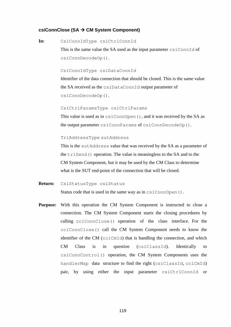
119
csiConnClose (SA ���� CM System Component)
In: CsiConnIdType csiCtrlConnId
This is the same value the SA used as the input parameter csiConnId of
csiConnDecodeOp() .
CsiConnIdType csiDataConnId
Identifier of the data connection that should be closed. This is the same value
the SA received as the csiDataConnId output parameter of
csiConnDecodeOp() .
CsiCtrlParamsType csiCtrlParams
This value is used as in csiConnOpen() , and it was received by the SA as
the output parameter csiConnParams of csiConnDecodeOp() .
TriAddressType sutAddress
This is the sutAddress value that was received by the SA as a parameter of
the triSend() operation. The value is meaningless to the SA and to the
CM System Component, but it may be used by the CM Class to determine
what is the SUT end-point of the connection that will be closed.
Return: CsiStatusType csiStatus
Status code that is used in the same way as in csiConnOpen() .
Purpose: With this operation the CM System Component is instructed to close a
connection. The CM System Component starts the closing procedures by
calling cciConnClose() operation of the class interface. For the
cciConnClose() call the CM System Component needs to know the
identifier of the CM (cciCmId ) that is handling the connection, and which
CM Class is in question (csiClassId ). Identically to
csiConnControl() operation, the CM System Components uses the
handlerMap data structure to find the right (csiClassId , cciCmId )
pair, by using either the input parameter csiCtrlConnId or

120
csiDataConnId as the key, depending on whether the csiDataConnId
is equal to constant csiNoConnId or not (Figure 4-8).
After calling cciConnClose() , the CM System Component can remove
the csiDataConnId to (csiClassId , cciCmId )–pair entry from its
handlerMap , if csiDataConnId is not equal to constant
csiNoConnId . Otherwise the csiDataConnId to (csiClassId ,
cciCmId) entry is removed (Figure 4-8). The CM System Component also
removes from its controlMap the mapping entry between
csiCtrlConnId and csiDataConnId .
NOTE: The SA may not remove the entries corresponding to
csiCtrlConnId and csiDataConnId from its tsiMap- data structure.
These entries are still needed by the CM to acknowledge to the test case
component when it has closed its connection with the SUT. This is explained
in Section 5.2 Connection Interface:ciClosed() and in A.3 Mapping
Interface.
When: When an existing data connection is closed in a test case with the Connection
Interface operation ciClose() , that is seen as this operation at the CSI
interface. MSC diagram B.4 shows how the operation propagates through the
interfaces.
CsiConnTerminate (SA ���� CM System Component)
In: CsiConnIdType csiConnId
SA generated identifier for the connection that should be terminated.
String reason
A string containing the termination reason. It can be for example “unmap”.
Purpose: This operation is used by the SA to instruct the CM System to forcefully
terminate a connection and the connection manager handling it. As the result,
all the buffered data related to the connection is immediately discarded and
the connection manager is terminated.

121
If the csiConnId is an identifier of a control connection, then all the related
data connections are also terminated (csiConnId contains identifier of a
port, and the CM System Component knows which ports are control ports,
hence it knows if csiConnId identifies a control connection). The CM
System Component can use controlMap to determine what are the
identifiers of the data connections to be terminated.
The identifier of the CM handling the connection(s) and its class can be found
from handlerMap . The CM System Component terminates all the related
connections by calling cciConnTerminate() operation for each of them
(see A.2.2 Operations for more details on calling the CM Class Interface
Operations).
The termination reason string reason is passed by the CM System
Component to the CM that is handling the connection, which in turn may
notify a test case component about termination of the connection with a report
message including the reason string.
After calling cciConnTerminate() , the CM System Component clears
the entries corresponding the identifier csiConnId from its handlerMap
and controlMap .
When: The difference between this and csiConnClose() operation is that this
operation is initiated by the SA as a result of triUnmap() operation, or if
the SA somehow detects an error that affects the connection. MSC diagram
B.6 shows the operation sequence this operation.
Note: This operation is always called when a component unmaps its port from
a TSI port, even if the connection using the TSI had been properly closed. In
this case the handlerMap has no entry for the csiConnId parameter
value, thus this operation returns without calling the cciConn-
Terminate() operation.

122
csiConnSend (SA ���� CM System Component)
In: CsiConnIdType csiDataConnId
Identifier of the data connection via which a message should be sent. This
value is the output parameter tsiDataPortId of csiConnDecodeOp()
operation.
CsiDataMsgType csiDataMsg
This value contains a sendMessage that should be delivered to the SUT. It
was received by the SA as the output parameter value csiConnParam of
csiConnDecodeOp() .
TriAddressType sutAddress
The sutAddress value that was received as a parameter of the
triSend() operation.
Return: CsiStatusType csiStatus
Status code of the operation call. This value is CSI_ERR, if the CM System
Component is unable to handle the operation request due to insufficient
resources, non-existing data connection, or due to any other reason that the
CM System Component can determine during the operation call. CSI_OK is
returned otherwise.
Purpose: With this operation the CM System is instructed to send a message to the
SUT. The CM System Component handles this by forwarding the request to
the CM that is handling the connection by calling cciConnData()
operation (see A.2.2 Operations for more details on calling the CM Class
Interface Operations). Identifier of the CM (cciCmId ) and its class can be
found from the system’s handlerMap data structure by using
csiDataConnId as the key.
When: TTCN-3 send statement executed using a data port that is mapped with a
TSI port is seen as this operation at the CM System Interface. MSC diagram
B.7 illustrates how the operation propagates through the interfaces.

123
csiConnCall (SA ���� CM System Component)
In: CsiConnIdType csiDataConnId
SA generated identifier of the data connection, for which a procedure call
should be performed. This value is derived by the SA from the tsiPortId
and componentId parameters of the triCall() operation.
CsiDataCallType csiDataCall
This value contains the signature of the procedure that should be called, and a
parameter list for it. This is derived by the SA from signatureId and
parameterList parameters of triCall() .
TriAddressType sutAddress
The sutAddress value that the SA received as a parameter of the
triCall() operation.
Return: CsiStatusType csiStatus
Return value that is used in the same way as in csiConnSend() .
Purpose: With this operation the CM System is instructed to perform a procedure call
at the SUT. The system handles this operation similarly to
csiConnSend() .
When: TTCN-3 call statement executed using a data port that is mapped with a
TSI port is seen as this operation at the CM System Interface. MSC diagram
B.8 shows how the operation propagates through the interfaces.
csiConnReply (SA ���� CM System Component)
In: CsiConnIdType csiDataConnId
SA generated identifier of the data connection, for which a procedure return
should be performed. This value is derived by the SA from the tsiPortId
and componentId parameters of the triReply() operation.
CsiDataReplyTypecsiDataReply
This value contains the signature of the procedure that should return,

124
parameter list for it, and a return value of the procedure. This is generated by
the SA from the signatureId , parameterList , and returnValue
values that it received as parameters of triReply() .
TriAddressType sutAddress
The sutAddress that was received as a parameter of the triReply()
operation.
Return: CsiStatusType csiStatus
Return value that is used in the same way as in csiConnSend() .
Purpose: With this operation the CM System is instructed to perform a procedure-
return at the SUT. The system handles this operation similarly to
csiConnSend() .
When: TTCN-3 reply statement executed using a data port that is mapped with a
TSI port is seen as this operation at the CM System Interface. MSC diagram
B.8 shows how the operation propagates though the interfaces.
csiConnRaise (SA ���� CM System Component)
In: CsiConnIdType csiDataConnId
SA generated identifier of the data connection, for which a procedure
exception raise should be performed. This value is derived by the SA from the
tsiPortId and componentId parameters of the triRaise()
operation.
CsiDataRaiseType csiDataRaise
This value contains the signature of the procedure that should raise an
exception, and a value for the exception, and it is generated by the SA from
signatureId , parameterList , and exception that it has received as
parameters of triRaise() .

125
TriAddressType sutAddress
The sutAddress value that was received as a parameter of the
triRaise() operation.
Return: CsiStatusType csiStatus
Status code that is used in the same way as in csiConnSend() .
Purpose: With this operation the CM System is instructed to raise an exception at the
SUT. The system handles this operation similarly to csiConnSend() .
When: TTCN-3 raise statement executed using a data port that is mapped with a
TSI port is seen as this operation at the CM System Interface. MSC diagram
B.8 shows how the operation propagates though the interfaces.
A.2 CM Class Interface
The CM Class Interface contains the operations between the CM System Component and
the CM Classes. Implementation of the CM Class Interface –operations, in which CM
System Component is the caller, is class specific, but the interface is the same for every
class. When the classes are registered into the CM System, the CM System Component
stores into its csiClassReg for each class a method (Table A-2:
CsiClassIfaceType ), with which it can the interface functions of the class (the
operations of Table A-4 in which CM System Component is the caller). These operations
Table A-4: Operations at CM Class Interface.
Category: Call Direction: Operation Identifier:
Class CM System Comp. � CM Class
CM System Comp. � CM Class
CM System Comp. � CM Class
cciInit
cciFinalize
cciReset
Connection CM System Comp. � CM Class
CM System Comp. � CM Class
CM System Comp. � CM Class
CM System Comp. � CM Class
CM System Comp. � CM Class
CM Class � CM System Comp.
cciConnOpen
cciConnControl
cciConnClose
cciConnData
cciConnTerminate
cciConnClosed
Encoding CM Class � CM System Comp. cciEncodeCiCtrlOp
126
are used by the CM System Component to distribute the operation requests it receives
from the SA to the right CMs. The interface also provides an operation with which a CM
Class can notify the CM System Component about a situation, in which it has closed a
connection without the CM System Component requesting for it. To make the transfer
syntax of the Connection Interface operations (5.2.3 On transfer syntax and encoding)
invisible to the classes, the CM System Component provides a procedure with which the
classes can do the encoding of CI operations. All the operations are procedure calls.
A.2.1 Data types
The abstract data types defined in Table A-5 are specific to the CM Class Interface. All
the other used data types are defined at the CM System Interface (Table A-2).
A.2.2 Operations
It was required in Section 4.3.4, that the connection category operations of the CM
System Interface operations the CM System Component provides to the SA are non-
blocking. This can be guaranteed by having an operation buffer in the CM System
Component, in which the operation requests are buffered. The CM System Component
can contain several worker threads that process the requests stored in the buffer one by
one when they have time. Alternatively, the every CM Class could have a similar buffer
into the operation requests done by the CM System Component to the CM Class are
buffered.
In the case every CM Class implements their an own operation buffers, the
cciConn*() operations become non-blocking to the CM System Component.
Therefore, the CM System Component should call the cciConn*() operations directly
from csiConn*() operation invocations, without using its own buffer, in order to avoid
Table A-5: Data types at CM Class Interface.
Type Identifier: Description:
CciCmIdType Base-class type for class specific CM identifiers. This is used to hide
the differences of the CM identifiers used by different CM Classes;
one class might address its CM instances with a memory address
value, while another class uses integer or character string identifiers.

127
double buffering. In the case the buffering is always done in the CM System Component,
then it is allowed that the cciConn*() operations are blocking to the CM System
Component. Regardless of the chosen buffering policy, the csiConn*() operations are
always non-blocking the SA.
The following procedure operations are specified at the CM Class Interface.
cciInit (CM System Component ���� CM Class)
Return: CsiStatusType status
Status code of the operation call. The return value is CSI_OK, if the class was
successfully initialized.
Purpose: This class specific operation is used to initialize the class in question. The
class may reserve memory dynamically, establish static connections with
SUT, or it may perform any other actions that has to be done by the class to
become usable.
When: The CM System Component calls this operation for every registered class
during the csiClassInit() operation.
cciFinalize (CM System Component ���� CM Class)
Purpose: This operation is opposite to the cciInit() operation. All the resources
reserved by the class are freed. The class must forcefully terminate any
possibly open connections.
When: The CM System Component calls this operation for every registered class
during the csiFinalize() operation, or for a single class when the
csiClassFinalize() is called.
cciReset (CM System Component ���� CM Class)
Purpose: This operation is used to clear all the connection related data and to terminate
any possibly existing connections.
128
When: The CM System Component calls this operation for every registered CM
Class as the result of the csiReset() operation.
cciConnOpen (CM System Component ���� CM Class)
In: CsiConnIdType csiCtrlConnId
Identifier of the control connection that is used to control the data connection
identified by the input parameter csiDataConnId . This is the same value
as the corresponding input parameter of the csiConnOpen() operation.
CsiConnIdType csiDataConnId
Identifier of the connection that should be opened. This is the same value as
the corresponding input parameter of the csiConnOpen() operation.
CsiClassDataType csiClassData
Class specific configuration data in encoded form. This the same value that is
stored in the input parameter csiCtrlParams of the csiConnOpen()
operation.
TriAddressType sutAddress
Value that can be used to specify the SUT end point of the connection, if it is
not encoded within the csiClassData parameter value. This the same
value that is stored in the input parameter sutAddress of the
csiConnOpen() operation.
Out: CciCmIdType cciCmId
Class generated value that identifies the CM that handles the opened
connection. This value remains valid until CM System Component calls either
cciClose() or cciTerminate() operation, or until the CM Class
notifies the CM System Component with cciClosed() operation that the
connection has been closed. No other opened connection may have the same
cciCmId value.
Return: CsiStatusType status
Status code of the operation call. The return value is CSI_OK, if the class had

129
enough resources to attempt to open a new connection and there were no
errors with the in-parameters of the operation.
Purpose: With this operation the CM Class is instructed to create a new connection
manager to handle the data connection which is identified by
csiDataConnId , and which controlled by the control connection identified
by csiCtrlConnId . As the return value of this operation, the CM System
Component receives the identifier of the new manager (cciCmId ) that
handles the connection. This identifier is used in all the other CM Class
Interface connection operations to address the right CM.
If the value of csiDataConnId is equal to csiNoConnId then this
operation is interpreted by the receiving CM Class as a request to open a
stand-alone control connection. What this means is class dependent. The
stand-alone control connections can be used for example for starting and
controlling class provided server entities. An example of this is given in
Section 5.4.7 TCP server example, in which a single component takes care of
starting and stopping of a TCP server entity, and other components then join
with it to handle any connections that the SUT establishes with the server
entity.
Successful return from this operation does not indicate that the connection is
usable; it only indicates that the class understood the request and will process
it. The CM System Component updates its handlerMap to contain the
information, that the opened connection is handled by the CM, that is
identified by the value of the output parameter cciCmId .
Once the connection has been opened, the CM handling the connection
reports this to the test case component by performing ciOpened()
operation. If for some reason it cannot open the connection, it performs
ciClosed() operation, and it also notifies the CM System Component with
the cciConnClosed() operation to clear its data structures of any
connection related data.

130
When: This operation is called as a result csiConnOpen() operation, which is
called as a result of ciOpen() operation of the Connection Interface. MSC
diagram B.1 shows how the operation propagates through the interfaces.
cciConnControl (CM System Component ���� CM Class)
In: CciCmIdType cciCmId
Identifier of the CM, that is handling the connection.
CsiClassDataType csiClassData .
Class specific configuration data in encoded form. This is the same value that
is stored in the input parameter csiCtrlParams of the
csiConnControl() operation.
TriAddressType sutAddress
Value that can be used to specify the SUT end point of the connection.
Return: CsiStatusType status
Status code of the operation call. Used in the same way as in
cciConnOpen() .
Purpose: With this operation the CM System Component component passes class
specific control data to the CM identified by cciCmId . The control data may
instruct the CM to modify the data connection related options, or it may
contain other class specific commands to the CM. What it does depends
completely on the CM Class.
When: This operation is called as a result of csiConnControl() operation,
which is called as a result of ciControl() operation of the Connection
Interface. MSC diagram B.2 shows how the operation propagates through the
interfaces.

131
cciConnClose (CM System Component ���� CM Class)
In: CciCmIdType cciCmId
Identifier of the CM, that is handling the connection that should be closed.
CsiClassDataType csiClassData .
Class specific configuration data in encoded form. This is the same value that
is stored in the input parameter csiCtrlParams of the
csiConnClose() operation.
TriAddressType sutAddress
Value that can be used to specify the SUT end point of the connection.
Return: CsiStatusType status
Status code of the operation call. Used in the same way as in
cciConnOpen() .
Purpose: With this operation, the class is instructed to close the connection handled by
the CM, which is identified by cciCmId . As the result, the class starts
shutdown procedures for the connection. When they have finished and
connection with SUT has been closed, the manager handling the connection
acknowledges this to the component of the connection by performing the
ciClosed() operation of Connection Interface. The shutdown procedures
may include transmission of all the data in send-buffer of the connection
manager, and waiting for any data that has not yet been received, but is
expected, that should be delivered to the component. What is done depends on
class and its class specific parameters in csiClassData . The cciCmId
value becomes invalid to the caller (CM System Component) when this
operation returns.
Once the connection manager has closed the connection with SUT, it reports
this to the test case component by performing the ciClosed() operation.

132
When: This operation is called as a result csiConnClose() operation, which is
called as a result of ciClose() operation of the Connection Interface. MSC
diagram B.4 shows how the operation propagates through the interfaces.
cciConnTerminate (CM System Component ���� CM Class)
In: CciCmIdType cciCmId
Identifier of the CM, that is handling the data connection which should be
terminated.
String reason
String containing the reason why the connection should be terminated.
Purpose: This operation is used for the special case, in which a CM is needed instructed
to forcefully shut down the connection it is handling and to discard
immediately all the connection related data.
The CM may try to send a ciClosed –indication (see 5.2.4 Operations) to
the component whose connection it is handling. If the termination cause was
that the component unmapped its control port, then this attempt by the CM
will fail, because the CM cannot get anymore the needed parameters from the
SA for a triEnqueueMsg() call by using the miLock() operation of the
Mapping Interface (see A.3 Mapping Interface), because the SA does not
have the information anymore.
When: This operation is called as a result csiConnTerminate() operation,
which can be a result of unmapping of the component port, which was being
used for a data or a control connection. In normal situation this operation is
never called, since the connections should be properly closed from the test
case with the ciClose() operation before the unmapping is done. If a
connection has been closed successfully, then the CM System Component
will not call this operation even if csiConnTerminate() is called. MSC
diagram B.6 shows how the operation propagates through the interfaces.

133
cciConnData (CM System Component ���� CM Class)
In: CciCmIdType cciCmId
Identifier of the CM that is handling the connection.
CsiOpIdType operationId
Operation identifier.
CsiDataParamsType dataParams
Operation specific parameter.
TriAddressType sutAddress
Value that can be used to specify the SUT end point of the connection that
should be closed.
Return: CsiStatusType status
Status code of the operation call. Used in the same way as in
cciConnOpen() .
Purpose: With this operation the CM System Component requests the CM identified by
the cciCmId to the handle the CSI interface communication operation
identified by operationId . The operation can be one of the following:
csiConnSend , csiConnCall , csiConnReply , or csiConnRaise .
dataParams contains the parameters for the operation. If this operation
returns successfully, then the CM of the connection attempts to perform the
requested operation.
When: This operation is called from csiConnSend , csiConnCall ,
csiConnReply , and csiConnRaise operations. MSC diagrams B.7 and
B.8 show how the operation propagates through the interfaces.
cciConnClosed (CM Class ���� CM System Component)
In: CsiConnIdType csiCtrlConnId
Identifier of the control connection that is used to control the data connection
identified by the input parameter csiDataConnId .

134
CsiConnIdType csiDataConnId
Identifier of the data connection that should be closed.
Purpose: With this operation a CM Class can indicate to the CM System Component,
that a previously opened connection has been closed. The CM System
Component can update its controlMap and handlerMap data structures
based on the input parameters. Figure 4-8 shows how the data structures and
identifiers are related.
The CM System Component removes from its controlMap the mapping
between the csiDataConnId and csiCtrlConnId .
If the value of csiDataConnId is other than the constant csiNoConnId ,
then the CM System Component uses the value of csiDataConnId to
remove the entry from handlerMap .
If the value of csiDataConnId is equal to constant csiNoConnId , then
the CM System Component uses the value of csiCtrlConnId to remove
the entry from handlerMap .
When: This operation is called by the CM Class, or by one its CMs, when the
connection with the SUT has been closed without the CM System Component
requesting for it. Possible reasons are SUT terminated connection, failed
attempt to establish a connection with the SUT, or an error on transmission
path. This operation is always called before a CM Class or CM performs a
ciClosed() operation, which is not a confirmation to the ciClose()
operation, but is a negative acknowledgement to the ciOpen() operation or
an indication to the test case that a connection has been closed. The CM
System Component has to be notified about the closed connection before
notifying the test case component, to avoid the situation, in which the test
case component might be able to try to re-open the closed connection before
the CM System Component has cleared the old entry. Both of the connections
would have the same identifier in this error situation in the CM System
Component.

135
Situations after which this operation may not be called are the following: the
CM System Component calls cciReset() , cciFinalize()
cciConnClose() , or cciConnTerminate() .
MSC diagram B.5 shows how the operation propagates through the interfaces.
cciEncodeCiCtrlOp (CM Class ���� CM System Component)
In: CsiCiOpIdType csiCiOpId
Identifier of the CI operation, for which a message is wanted to be encoded.
The value can be csiCiOpenedId , csiCiStatusId , or
csiCiClosedId .
String csiClassId
Identifier of the class calling this operation. This is the same identifier with
which the class was registered into the CM System Component (with
operation csiClassReg() ), and which is used as the field name of this
class in the class field of the CI control operation messages (Definitions
can be found in Section 5.2.2 Type definitions).
CsiConnIdType csiDataConnId
Identifier of the data connection, for which the calling class wants to encode a
Connection Interface control category operation message (listed in Section 5.2
Connection Interface).
CsiClassDataType csiClassData
Class specific configuration data in encoded form. The calling CM Class has
done the encoding of the data.
Out: TriMessageType receivedMessage
A value containing an encoded CI interface control category operation
message in the form of CmSysControlMessage (defined in Table 5-3).
Purpose: With this operation the CM Classes can request the CM System Component
to encode a Connection Interface control message of type CiOpened ,
136
CiStatus , or CiClosed , into the form of CmSysControlMessage .
This makes the transfer syntax of the control messages invisible to the CM
Classes, and each of the classes does not have to implement their own encoder
for the control messages, except for their class specific data part.
After calling this operation, the out-parameter value receivedMessage
can be sent by the caller to a test case component with the
triEnqueueMsg() operation.
NOTE: There exists no decode operation for the CM Classes, because the
decoding (excluding class specific part) of the incoming CI control messages
is done by the CM System Component within the csiConnDecodeOp()
operation.
When: This operation is called by a CM Class or a CM when it wants to create an
encoded CI control message to be sent to a component (MSC diagrams B.1,
B.3, B.4, B.5, B.6, and B.9).
A.3 Mapping Interface
Mapping Interface provides operations, with which the CM Classes and the CMs can
query from the SA the current TSI mapping information of a connection by a connection
identifier. The mapping information of a connection consist of a (TriPortId
tsiPortId , TriComponentIdType componentId )–pair, which can be used as
the parameter of a triEnqueue*() operation call.
The mapping information is stored into a single shared data structure called tsiMap in
the SA, instead of distributing copies of it to the CMs when new connections are being
created. The reason for this is that the port mappings may changed during a test case,
causing a copy of a (tsiPortId , componentId )–pair to become out of date. TRI
interface standard does not specify what is the result of calling triEnqueue*()
operations with invalid parameters. The used TTCN-3 tool may choose to ignore the
operation call without affecting the verdict of the test case, or it may set error test
verdict, or do something else. To avoid this situation with unknown results, it is required,

137
that the TSI mapping information stored in tsiMap is not readable by a CM or CM
Class, when it is being modified by the SA, and it cannot be modified by the SA, when a
CM or CM Class is about to call a triEnqueue*() operation with a (tsiPortId ,
ComponentId )–pair.
The specified Mapping Interface operations provide the means with which a CM or CM
Class can signal to the SA, that it wants to reserve a (tsiPortId , componentId )–
pair from tsiMap into its use, or that it does not need the pair anymore. In addition to
this functionality, the implementations of the TRI interface operations triMap() and
triUnmap() have to be such that they take into account the reservations before
updating the information stored in tsiMap . If a (tsiPortId , componentId )–pair
has been reserved, then the SA must wait for the pair to become unreserved, until it may
modify the mapping information related to the pair and complete the TRI operation in
question.
The operations with which the SA handles the reservations and stores the mapping
information into the tsiMap are internal to the SA and outside the scope of this
document.
A.3.1 Data types
This interface has no own data types.
A.3.2 Operations
miLock (CM ���� SA)
In: CsiConnIdType csiConnId
Identifier of a connection, whose (tsiPortId , componentId )–pair is
wanted to be locked. The CM received this value when the connection was
opened.
Out: TriPortIdType tsiPortId
tsiPortId corresponding to the input parameter csiConnId .

138
TriComponentIdType componentId
componentId corresponding to the input parameter csiConnId .
Return: CsiStatusType status
Status code of the operation. The value is CSI_OK, if the pair corresponding
to the csiConnId existed and was successfully reserved. CSI_ERR is
returned if there exists no entry for the csiConnId that could have been
reserved.
Purpose: With this operation a CM can retrieve and reserve from tsiMap the
tsiPortId and componentId values corresponding to the csiConnId .
The values remain reserved for the CM until it calls the miUnlock()
operation with the same csiConnId .
If the values corresponding to csiConnId have already been reserved for an
other caller, this operations blocks until they have been released with the
miUnlock() operation.
The implementations of the TRI interface operations triMap() and
triUnmap() operations has to be such that if a CM has reserved a certain
(tsiPortId , componentId )–pair, and the TRI operation would have an
effect on this pair, then the TRI operation will block until the CM has released
the pair by calling the miUnlock() operation. Similarly, the miLock()
operation will block if the triMap() or the triUnmap() operation is
being called by the TE.
When: The CM calls this operation right before it is going to call a
triEnqueue*() operation. It also calls the miUnlock() operation right
after the triEnqueue * () operation has finished.
miUnlock (CM ���� SA)
In: CsiConnIdType csiConnId
Identifier of a connection, whose (tsiPortId , componentId )–pair is
139
wanted to be unlocked. The CM received this value when the connection was
opened.
Purpose: With this operation a CM can unlock the (tsiPortId , componentId )–
pair identified by the input parameter csiConnId . The CM must have
locked the pair previously with the miLock() operation to prevent any
modifications to the mapping information for the duration of a
triEnqueue * () operation call.
When: The CM calls this operation right after its triEnqueue*() operation call
has returned, not to unnecessarily prevent the TE and the SA from doing any
possibly modifications to the mapping information.

140
B MSC DIAGRAMS
This section contains selected message sequence chart diagrams, which illustrate how the
interfaces and their operations specified in Chapter 5 and Appendix A work together.
B.1 Open
This MSC diagram shows how a data connection is opened from the test case by a
component and what interface operations this results in. If the open procedure fails, then
the CM closes the connection as in MSC B.5 Closed, by notifying the CM System
Component and the test case component.
msc Open
:SA:CmSystem
Comp.:CmClass:TE:Component :SUT
controlPort .send(ciOpen(tsiDataPort, openParams )) to sutAddress
csiConnDecodeOp(ctrlConnId, sendMessage(CmSysControlMessage) )
csiConnOpenId, dataConnId, csiCtrlParams(csiClassId , csiClassData ))
csiConnOpen(ctrlConnId, dataConnId, csiCtrlParams(csiClassId, c siClassData), sutAddress )
cciConnOpen(ctrlConnId, dataConnId, csiClassData, sutAddress)
cciCmId
New CM is created or assigned to handle the
connection.
Can be an activated alt-statement default alternative, which handles the acknowledgements to ciOpen messages.
controlPort .receive(ciOpened )
triSend(componentId, tsiPortId, sutAddress, sendMessage(CmS ysControlMessage corresponding to ciOpen) )
ciOpened(tsiDataPort, openedParams)
Open acknowledgement has been received
tsiPortId contains the identifier of the TSI port, that is mapped with controlPort .
CM System decodes the following information from sendMessage: ciOperationId , tsiPortName , tsiPortIndex , classId, and classData.
dataConnId to cciCmId mapping is stored into handlerMap .
ctrlConnId to dataConnId mapping is stored into controlMap.
SA derives CsiConnIdType ctrlConnId from TriPortIdType tsiPortId, and TriComponentIdType componentId.
miLock(ctrlConnId )
tsiCtrlPortId , componentId
miUnlock(ctrlConnId )
Class and CM Specific operations to handle the requ est
Connection establishment
:CM
Connection is ready
csiConnOpenId is returned based on the decoded ciOperationId value. This tells the SA which CSI-operation to call, which is csiConnOpen() in this case.
dataConnId was generated by the CM System Comp. from tsiPortName, tsiPortIndex, and the componentIdString field of ctrlConnId .
cciEncodeCiCtrlOp(csiCiOpenedId , ownClassId, csiDataConnId, csiClassData(openedParams) )
cmSysControlMessage corresponding to ciOpened
The CM asks the CM System Component to build a Connection Interface operation message in the transfer syntax form.
csiDataConnId contains the identifier of the TSI port of the connection (tsiDataPort ).
triEnqueueMsg(tsiCtrlPortId , sutAddress , componentId , receivedMessage (CmSysControlMessage ))

141
B.2 Control
This MSC diagram illustrates how a connection can be controlled, when it has been
successfully opened as shown in MSC B.1 Open.
msc Control
Status
:SA:CmSystem
Comp.:CmClass:TE:Component :SUT
controlPort .send(ciControl(tsiDataPort, controlParams )) to sutAddress
csiConnDecodeOp(ctrlConnId, sendMessage(CmSysControlMessage) )
csiConnControlId, dataConnId, csiCtrlParams(csiClas sId, csiClassData ))
csiConnControl(ctrlConnId , dataConnId, csiCtrlParams(csiClassId, csiClassData) , sutAddress )
cciConnControl(cciCmId, csiClassData, sutAddress)
triSend(componentId, tsiPortId, sutAddress, sendMessage(CmS ysControlMessage corresponding to ciControl) )
tsiPortId contains the identifier of the TSI port, that is mapped with controlPort .
CM System decodes the following information from sendMessage: ciOperationId , tsiPortName , tsiPortIndex , classId, and classData.
SA derives CsiConnIdType ctrlConnId from TriPortIdType tsiPortId, and TriComponentIdType componentId.
csiConnControlId is returned because of the decoded ciOperationId value. The SA knows to call csiConnControl() because of the csiConnControlId value.
dataConnId is generated by the CM System Component from tsiPortName, tsiPortIndex, and the componentIdString field of ctrlConnId .
Class and CM specific operations to handle the requ est
Control(Control)
:CM
Opt
cciCmId corresponding to dataConnId can be found from handlerMap, unless dataConnId is equal to constantcsiNoConnId. If dataConnId is equal to csiNoConnId, meaning that no data port had been specified, the cciCmId value is found from the handlerMap by using ctrlConnId as the key.

142
B.3 Status
This MSC diagram illustrates how a connection manager can send a status message
regarding a connection it is handling to the test case component that opened the
connection.
msc Status
:SA:CmSystem
Comp.:CmClass:TE:Component :SUT
Can be an activated alt-statement default alternative, which handles the ciStatus messages.
controlPort .receive(ciStatus)
ciStatus(tsiDataPort, statusParams)
Status report has been received
miLock(ctrlConnId )
tsiCtrlPortId , componentId
miUnlock(ctrlConnId )
:CM
A connection has been opened as described in MSC Open.The CM knows the dataConnId of the connection, and the ctrlConnId of the related control connection.
CM decides to send a status report concerning a connection it is handling.
cciEncodeCiCtrlOp(csiCiStatusId , csiClassId, csiDataConnId, csiClassData(statusParams) )
csiDataConnId contains the identifier of the TSI port of the connection (tsiDataPort) .
ctrlConnId was passed to the class of the CM when the connection was opened. If the CM does not know it, it can ask it from its class.
cmSysControlMessage corresponding to ciStatus
The CM asks the CM System to build a Connection Interface operation message in the transfer syntax form.
triEnqueueMsg(tsiCtrlPortId , sutAddress , componentId , receivedMessage (cmSysControlMessage) )

143
B.4 Close
This MSC diagram illustrates how connection is closed when this is requested by a test
case component.
msc Close
:SA:CmSystem
Comp.:CmClass:TE:Component :SUT:CM
controlPort .send(ciClose(tsiDataPort, closeParams )) to sutAddress
csiConnDecodeOp(ctrlConnId, sendMessage(CmSysControlMessage) )
csiConnClose(ctrlConnId , dataConnId, csiCtrlParams(csiClassId, csiClassData) , sutAddress )
cciConnClose(cciCmId, csiCloseParam, sutAddress)
triSend(componentId, tsiPortId, sutAddress, sendMessage(CmS ysControlMessage corresponding to ciClose) )
Class and CM specific operations to handle the requ est
This may include receipt of data from the SUT, and sending of buffered messages to the SUT. What is done depends on the instructions contained within the class specific data.
Close connection
Closing procedures have finished
Closing procedures
Can be an activated alt-statement default alternative, which handles ciClosed messages.
CM System decodes the following information from sendMessage: ciOperationId , tsiPortName , tsiPortIndex , classId, and classData.
csiConnCloseId, dataConnId, csiCtrlParams(csiClassI d, csiClassData ))
SA derives CsiConnIdType ctrlConnId from TriPortIdType tsiPortId, and TriComponentIdType componentId.
csiConnCloseId is returned based on the decoded ciOperationId value. The SA knows to call csiConnClose() by csiConnCloseId .
dataConnId is generated by the CM System from tsiPortName, tsiPortIndex, and the componentIdString field of ctrlConnId .
tsiPortId contains the identifier of the TSI port, that is mapped with controlPort .
dataConnId to cciCmId mapping is removed from handlerMap . Also, if this was the last data connection the component had, then the related control connection entry is removed from controlMap .
controlPort .receive(ciClosed)
ciClosed(tsiDataPort,closedParams), sutAddress
Closed indication has been received
miLock(ctrlConnId )
tsiCtrlPortId , componentId
miUnlock(ctrlConnId )
cciCmId corresponding to dataConnId can be found from handlerMap .
cciEncodeCiCtrlOp(csiCiClosedId , csiClassId, csiDataConnId, csiClassData(closedParams) )
cmSysControlMessage corresponding to ciOpened
The CM asks the CM System to build a Connection Interface operation message in the transfer syntax form.
csiDataConnId contains the identifier of the TSI port of the connection (tsiDataPort ).
triEnqueueMsg(tsiCtrlPortId , sutAddress , componentId , receivedMessage (CmSysControlMessage) )

144
B.5 Closed
This MSC diagram illustrates how a connection is closed when this is initiated by a CM
Class or a CM, as result of failure to open a new connection or when an existing
connection is lost. The CM notifies first the CM System Component about the event, after
which it notifies the test case component.
msc Closed
:SA:CmSystem
Comp.:CmClass:TE:Component :SUT:CM
ciClosed(tsiDataPortId), sutAddress
controlPort .receive(ciClosed)miLock(ctrlConnId )
tsiCtrlPortId , componentId
miUnlock(ctrlConnId )
cciEncodeCiCtrlOp(csiCiClosedId , csiClassId, csiDataConnId, csiClassData(closedParams) )
cmSysControlMessage corresponding to ciClosed
The CM asks the CM System to build a Connection Interface control-operation message in the transfer syntax form.
triEnqueueMsg(tsiCtrlPortId , sutAddress , componentId , receivedMessage(CmSysControlMessage corresponding t o ciClosed )
csiDataConnId contains the identifier of the TSI port of the connection (tsiDataPort ).
Connection manager detectsthat either it cannot open a new connection as requested by the Component, or that an existing
connection with the SUT has been lost without Component requesting for it.
cciConnClosed(csiCtrlConnId, csiDataConnId )The CM System Component clears its controlMap and handlerMap data structures from the entries corresponding to the input parameters.
Mapping data structures updated
Can be an activated alt-statement default alternative, which handles ciClosed messages.

145
B.6 Terminate
This MSC diagram illustrates how a connection is terminated by the SA, when a
component unmaps its port, for which it opened a connection, but not explicitly closed by
sending a ciClose message as in MSC B.4. csiTerminate() has no effect if there
are no open connections, and cciTerminate() is not called.
msc Terminate
:SA:CmSystem
Comp.:CmClass:TE:Component :SUT:CM
Component has a control port connection identified with ctrlConnId , and a data connection identified with dataConnId.ctrlConnId is associated with port controlPort , and dataConnId is associated with port dataPort .
unmap(controlPort ) or unmap(dataPort )
triUnmap(compPortId , tsiPortId )
csiTerminate(connId, reason=”unmap” )
cciTerminate(cciCmId, reason=”unmap” )
Class and CM specific operations to handle the requ est
Terminate
ciClosed(tsiDataPortId), sutAddress
[controlPort]
Alt (the unmapped port was dataPort)
(Terminate)
Loop (”every data connection related to the control connection is terminated”)
Class and CM specific operations to handle the requ est like above
No termination indications can be sent to the component, because it is not reachable via the unmapped control port
cciTerminate(cciCmId, reason=”unmap” )
Can be an activated alt-statement default alternative, which handles the acknowledgements to ciClosed messages.
controlPort .receive(ciClosed)
cciCmId corresponding to ConnId can be found from handlerMap.
Identifiers of the data connections related to the unmapped control connection can be found from controlMap by using ctrlConnId as the key.
handlerMap and controlMap are cleared from the entries corresponding to the connection
Closing procedures have finishedmiLock(ctrlConnId )
tsiCtrlPortId , componentId
miUnlock(ctrlConnId )
cciEncodeCiCtrlOp(csiCiClosedId , csiClassId, csiDataConnId, csiClassData(closedParams) )
cmSysControlMessage corresponding to ciClosed
The CM asks the CM System to build a Connection Interface control-operation message in the transfer syntax form.
triEnqueueMsg(tsiCtrlPortId , sutAddress , componentId , receivedMessage(CmSysControlMessage corresponding t o ciClosed )
csiDataConnId contains the identifier of the TSI port of the connection (tsiDataPort ).
handlerMap and controlMap are cleared from the entries corresponding to the connection

146
B.7 Message
This MSC diagram illustrates how a message is sent by a component via a data port, for
which it has previously opened a connection.
B.8 Procedure
This MSC diagram illustrates how a component performs a procedure call via a data port,
for which it has previously opened a connection.
msc Message
:SA:CmSystem
Comp.:CmClass:TE:Component :CM :SUT
dataPort .send(msg) to sutAddress
csiConnDecodeOp(tsiPortConnId, sendMessage(msg) )
csiConnSendId, dataConnId, csiDataMsg(sendMessage(m sg))
csiConnSend(dataConnId, csiDataMsg(sendMessage(msg)), sutAddres s )
cciConnData(cciCmId, csiConnSendId, csiDataMsg(sendMessage(msg)), sutAddress )
triSend(componentId, tsiPortId, sutAddress, sendMessage(msg ) )
msg
Class and CM specific operations to handle the requ est
Deliver msg
tsiPortId contains the identifier of the TSI port, that is mapped with dataPort .
csiConnSend() is called because of the return value csiConnOpenId.
cciCmId corresponding to dataConnId can be found from handlerMap .
dataConnId contains the same value as the received tsiPortConnId.
The SA derives CsiConnIdType tsiPortConnId from TriPortIdType tsiPortId, and TriComponentIdType componentId.
csiConnSendId is returned because csiConnDecodeOp() recognizes the port identifier stored in CsiConnIdType tsiPortConnId as one of the data ports. The SA knowns to call csiConnSend() because of csiConnSendId value
Depending on the implementation, it is possible, that the cciConnData() operation is called from within csiConnSend() operation.
Depending on the implementation, the cciConnData() operation may enqueue the to-be-sent message directly into a transmission buffer of the CM, without first passing it to the class, which would forward it to its CM.
It is only required that the csiConnSend( ) is not a blocking operation to the SA.
msc Procedure
:SA:CmSystem
Comp.:CmClass:TE:Component :SUT:CM
dataPort .call(signatureId, parameterList ) to sutAddress
This same scenario is used for the reply() and raise() port statements. The used corresponding CSI operations are csiConnReply() and csiConnRaise().
triCall(componentId, tsiPortId, sutAddress, signatureId, pa rameterList)
csiConnCall(dataConnId , csiDataCall(signatureId, parameterList), sutAddress )
cciConnData(cciCmId, csiConnCallId, csiDataCall, sutAddress )
Procedure call
Class and CM specific operations to handle the requ est
Make procedure call
cciCmId corresponding to dataConnId can be found from handlerMap .
tsiPortId contains the identifier of the TSI port, that is mapped with dataPort .
SA derives CsiConnIdType dataConnId from TriPortIdType tsiPortId, and TriComponentIdType componentId.
csiConnCall() operation is called directly without calling csiConnDecodeOp(), because the TRI-operation is triCall , which is not used for passing control messages to the CM System.
Depending on the implementation, it is possible, that the cciConnData() operation is called from within csiConnCall() operation.
Depending on the implementation, the cciConnData() operation may enqueue the to-be-performed procedure operation directly into a transmission buffer of the CM, without first passing it to the class, which would forward it to its CM.
It is only required that the csiConnCall( ) is not a blocking operation to the SA.

147
B.9 Receipt of a message or procedure operation
This MSC diagram illustrates how both message- and procedure-based communication
events concerning a data connection are enqueued by the CM to the test case component
that opened the data connection.
msc Receipt
:SA:CmSystem
Comp.:CmClass:TE:Component :SUT:CM
msgdataPort .receive(expectedMsg)
msg, sutAddress
[procedure based communication]
Alt (message based communication)
Procedure call
triEnqueueCall(tsiDataPortId, sutAddress, componentId, signatureId , parameterList)
dataPort .getcall(expectedSignatureId, expectedParameterList)
signatureId, parameterList, sutAddress
Procedure return and exception raise are handled similarly with getreply(), triEnqueueReply() , and with catch() , triEnqueueException() operations.
triEnqueueMsg(tsiDataPortId , sutAddress , componentId , receivedMessage (msg) )
miLock(dataConnId )
tsiDataPortId , componentId
miUnlock(dataConnId )
dataConnId was passed to the class of the CM when the connection was opened. If the CM does not know it, it can ask it from its class.
miLock(dataConnId )
tsiDataPortId , componentId
miUnlock(dataConnId )
SUT is blocked unti corresponding
dataPort .reply()statement is executed
in the test case