
General Product Guide 2013 - holodko.ru · General Product Guide 2013 ... ZR Copeland Scroll™...
296
http://holodko.ru/ C o p ela n d brand products Alco Controls General Product Guide 2013 For Refrigeration, Air Conditioning and Heat Pumps Climate Technologies
Transcript of General Product Guide 2013 - holodko.ru · General Product Guide 2013 ... ZR Copeland Scroll™...

http://holodko.ru/
C o p e la n dbrand products
Alco Controls
General Product Guide 2013For Refrigeration, Air Conditioning and Heat Pumps
Climate Technologies

http://holodko.ru/
♦EMERSON.Climate Technologies
C a p B la n d ' Alco Controlsbrand products
" n fiE la n ii Scroll'
'opelantl Scroll'digital
’ope/and Scroll'digital heating
'apelantl Scroll'variable speed
DWM COPELAND
C o p e la n d "EazyCooF
Note:The components listed in this catalogue are not released for use with caustic, poisonous or flammable substances.Emerson Climate Technologies cannot be held responsible for any damage caused by using these substances.
General InformationTechnical data provided herein is collected with scrutiny. However, errors and misprinting remain reserved. The technical data is presented for informational purposes only and they are not to be construed as warranties or guarantees, express or implied, regarding the products or services described or their use or applicability.
Technical data may be updated; should you require confirmation with respect to a specific value, please contact Emerson Climate Technologies GmbH and clearly state the information you require.
Emerson Climate Technologies GmbH and/or its affiliates (collectively “ Emerson”) shall not be liable for errors in the stated capacities, dimensions, etc., as well as typographic errors. Products, specifications, designs and technical data contained in this document are subject to modification by us without prior notice. Illustrations are not binding.
Emerson does not assume responsibility for the selection, use or maintenance of any product. Responsibility for proper selection, use and maintenance of any product remains solely with the purchaser and end-user.
The information given herein is based on data and tests which Emerson Climate Technologies GmbH believes to be reliable. Such information is intended for use by individuals having the appropriate technical knowledge and skills, at their own discretion and risk. Our products are designed and adapted for stationary application. When using our products in mobile applications, our products might fail. The suitability for such mobile applications has to be assured by the plant manufacturer; for this purpose appropriate tests might be necessary.
2

http://holodko.ru/
Scroll Compressors
- Comfort
• ZR Copeland Scroll™ Compressor Range for R407C and R134a
• ZP Copeland Scroll™ Compressor Range for R410A
• ZPD & ZRD Copeland Digital Scroll™ Compressor Range
• ZH Copeland Scroll™ Compressor Range
• ZPV & ZHW Copeland Scroll™ Variable Speed Compressor Range
• ZRH & ZBH Copeland Scroll™ Horizontal Compressor Range
- Refrigeration
•ZB Copeland Scroll™ Compressor Range for Medium Temperature Refrigeration
• ZF Copeland Scroll™ Compressor Range for Low Temperature Refrigeration
• ZFD & ZBD Copeland Digital Scroll™ Compressor Range for Low and Medium Temperature Refrigeration
• ZO & ZOD Copeland Scroll™ Compressor Range for CO2-Subcritical Refrigeration
• Sound Shell for Copeland Scroll™ Compressors
• Booster Compressors - S-Series & Scroll
Semi-Hermetic Reciprocating Compressors
- K and L Reciprocating Compressor Range
- Discus™ Reciprocating Compressor Range
- Copeland™ Stream With CoreSense™ Diagnostics, Semi-Hermetic Reciprocating Compressors For HFC
- Copeland™ Stream Digital with CoreSense™ Diagnostics for Continuous Capacity Modulation
- Copeland™ Stream Compressors with CoreSense™ Diagnostics for R744-Transcritical Applications
- S-Series Reciprocating Compressor Range
Condensing Units
- Copeland EazyCool™ Outdoor Condensing Units with Scroll Compressors
- Copeland EazyCool™ Outdoor Condensing Units for Refrigeration Networks
- Copeland EazyCool™ ZX Outdoor Condensing Units with Scroll Compressors
- Copeland Scroll™ Indoor Condensing Units for Refrigeration
- Copeland Scroll™ Digital Receiver Unit HLR
- Semi-Hermetic Condensing Units DK/DL
- Standard Semi-Hermetic Condensing Units
- Condensing Units with Semi-Hermetic Discus™ Compressors
Compressor Motor Codes Table
Controls
- Alco Keyword Register
- Electrical Control Valves
- Electronic Controllers and Sensors
- Thermo™ Expansion Valves
- Solenoid Valves
- Mechanical Pressure Regulators
- Pressure Controls and Thermostats
- System Protectors and Moisture Indicators
- Oil Management Components
- Suction Accumulators, Ball Valves and Oil Test Kit
- Accessories & Spare Parts
10
14
18
22
26
28
32
36
40
44
46
48
52
56
62
66
70
72
80
86
90
94
102
106
110
114
119
124
127
155
187
219
229
237
253
273
281
285
3

http://holodko.ru/

http://holodko.ru/
Pioneering Technologies For Best-In-Class Products
Emerson Climate Technologies is the world's leading provider
of heating, ventilation, air conditioning and refrigeration
solutions for residential, industrial and commercial applications,
supporting the industry with advanced technology, technical
support and training services.
For more than 80 years we have been introducing innovative
technology to the market, from the first semi-hermetic and
hermetic compressors in the 1940s and 1950s, plus the high
efficiency Discus, air conditioning and heating scroll compressors
in the 1980s and 1990s, to the new Stream semi-hermetics, the
digital scroll compressor and the variable speed scroll with drive
technology of today.
Based on this, we have developed an unequalled range of
solutions for the refrigeration and air conditioning markets. In
recent years, we have become a major solutions provider to the
heat pump industry. Our range of Copeland™ brand products
and Alco Controls addresses the very diverse needs of all of these
markets. With scrolls and semi-hermetic compressors available
for all main refrigerants, equipped with smart electronics and
capable of Digital and Variable Speed Modulation, Emerson
Climate Technologies has taken compression technology to new
heights.
1,300 employees develop and deliver Em erson's high class tech
nology and manufacture our products in four European plants:
Belgium, Northern Ireland and the Czech Republic (2 plants).
R&D centres in Welkenraedt (Belgium), Mikulov (Czech Republic)
and Waiblingen (Germany) enable new developments not only
to meet our customers' requirements but also to redefine the
limits of technology.
With sales points in Germany, France, Spain, Italy, the United
Kingdom, Scandinavia, Benelux, Poland, as well as in Eastern
Europe and Russia, Emerson Climate Technologies supports its
European customers in a lean and efficient manner.
Our new 2013 product catalogue gives a comprehensive
overview of Copeland brand and Alco Controls products. Have a
look and discover more about our broad and innovative product
ranges:
• the Variable Speed technology for residential scroll
compressors, with improved efficiency and optimized
operating envelope,
• and the new commercial scroll compressor models
(ZP236K and ZP296K) now equipped with the CoreSense™
Communications module.
To harmonize our semi-hermetic compressor ranges in terms
of color and branding, we are changing the product brand and
the nomenclature of the semi-hermetic compressors for the
K & L-Series and the Discus-range. We will start using the well-
known ‘Copeland brand products' label replacing “DWM
Copeland” and change the compressor color from grey to black.
More in-depth technical data is available through our user-friendly
Copeland selection software tool and Alco Controls selection tool
accessible via our web pages www.emersonclimate.eu;
For individual consultancy and service please contact your
European sales office.
5

http://holodko.ru/
6

http://holodko.ru/
Copeland Scroll™ Compressors
With the launch of scroll technology in the mid 1980s Emerson
revolutionized the market setting new standards in the air
conditioning industry. Since then, Copeland Scroll has become
the reference not only in air conditioning but in refrigeration
and heating applications too. Thousands of customers trust our
proprietary technology: today, over 80 million Copeland Scrolls
are installed worldwide, more than any other scroll compressor
brand. Copeland Scroll compressors range from 1.5 to 40 hp and
are designed to work with all the main refrigerants, including
CO2. With compressors built in both vertical and horizontal
versions, and capable of digital modulation, Emerson Climate
Technologies has expanded the capability of scroll technology to
new heights.
Applications for scroll compressors continue to grow thanks to
innovation and adaptation. Industry as a whole has embraced its
responsibility to put the environment first in its list ofpriorities, and
this has led to strategic imperatives such as the need to introduce
larger capacity scrolls with improved seasonal performance,
modulated systems and product designed for use with “green”
refrigerants such as CO2. Emerson Climate Technologies is staying
abreast of these challenges by successfully further developing its
technologies in each of these areas.
Additional innovations such as Enhanced Vapor Injection, the
new Variable Speed scroll with drive technology for heat pump
compressors or the design of the Emerson Climate Technologies
sound shell give manufacturers, installers and end users the
right tools to reduce the carbon footprint of their installations,
optimize system design, efficiency, sound and reliability, while
ensuring long equipment life time and minimizing capital and
operating costs.
Today we offer the broadest scroll product line-up in the market

http://holodko.ru/
http://holodko.ru/
Comfort Applications
For decades, Emerson Climate Technologies has driven advance
ment in the air conditioning and heat pump industry, leading the
field with engineering products and systems that maximize the
comfort of office and living spaces - while minimizing costs and
inefficiencies.
Copeland Scroll™ compressors are designed to deliver the high
est performance in residential and commercial applications.
Thanks to the widest selection of air conditioning and heating op
timized scroll compressors with a range from 1.5 up to 40 hp and
the option to combine single compressors in even and uneven
tandem and trio versions increasing overall capacity up to 120
hp per circuit, it has never been easier to match all desired appli
cations with the highest efficiency and reliability. Whether your
need is a cooling optimized, heating optimized or reversible unit,
you will find the most advanced technology within our range.
A further innovation has been the introduction of ZH compres
sors with Enhanced Vapor Injection technology. This technology,
when applied in space heating and tap water production, permits
the replacement of traditional boilers without changing the ra
diators. Additional benefits are the reduction of the discharge
temperature and the extension of the operating envelope for the
production of high temperature water. ZH compressors are avail
able for R407C and also for R410A - the latter option for both resi
dential and commercial applications - allowing OEMs to design
more efficient and compact equipment.
New commercial scroll compressor models such as ZP236K and
ZP296K are now equipped with the CoreSense™ Communica
tions module. This added feature unlocks advanced diagnostics,
protection and communication in Copeland compressors and
sends data to the main system controller via modbus RS485.
One of the most important recent introductions for comfort ap
plications has been the launch of the Variable Speed technology
for scroll compressors. The combination of brushless permanent
magnet motor and inverter drive, that continuously adapts the
compressor speed, improves the efficiency and optimizes it
throughout the operating envelope. This technology was first
introduced as a solution for heat pump applications (ZHW) and
will be extended in 2013 to reversible and low temperature appli
cations, with the introduction of the ZPV R410A Variable Speed
Scroll.
9

http://holodko.ru/
ZR Copeland Scroll™ Compressor Range for R407C and R134aZR Copeland Scroll compressors, for R407C and R134a, for comfort and process/precision cooling applications.
Applied in the air conditioning and comfort industry for water chillers, rooftops and close control unit applications, scroll compressors are now the most used compression technology replacing reciprocating and screw compressors due to its undeniable superiority. Several, fully Copeland™ qualified, multiple compressor assemblies (tandem and trio) are available to allow the use of Copeland Scroll compressors into large capacity systems (ex. up to 500kW air cooled chillers) able to deliver optimal comfort, low operating cost with higher seasonal efficiency (ESEER).
The range of products goes from the ZR18 (1.5Hp) to the ZR380 (30hp)
ZR Scroll Compressor
ZR Scroll Compressor Line-up
ZR (1Ph)
ZR (3Ph) • • • •
kW Cooling0 10 20 30 40 50 60 70 80 90
Tandem • • • • • • • • • • • • •
Trio • • • • • • • •
kW Cooling0 10 20 30 40 50 60 70 80 90 1 0 0 1 1 0 1 2 0 130 140 150 160 170 180 190 200 210 220 230 240 250
Conditions EN12900: Evaporating 5°C, Condensing 50°C, Superheat 10K, Subcooling 0K
Features and Benefits
• Copeland Scroll axial and radial compliance for superior reliability and efficiency
• Wide scroll line-up for R407C and R134a• Low TEWI (Total Equivalent Warming Impact)• Low sound and vibration level• Low oil circulation rate• Copeland qualified tandem and trio configurations for
superior seasonal efficiency (ESEER)
Maximum Allowable Pressure (PS)
• ZR18 to ZR81:Low Side PS 20 bar(g) / High Side PS 29.5 bar(g)
• ZR94 to ZR380:Low Side PS 20 bar(g) / High Side PS 32 bar(g)
Operating Envelope R407C
Evaporating Temperature °C R407C - 10K Superheat
— ZR 18-81 - - - ZR 144
— — ZR 94-190 - - - ZR 250-380
10
http://holodko.ru/
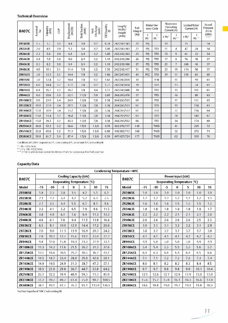
Technical Overview
R407CNo
min
alhp
Capa
city
(kW
) POC
Disp
lace
men
t(m
3/h)
Stub
Suct
ion
(inch
)
Stub
Disc
harg
e(in
ch)
Oil Q
uant
ity
(l)
Length/Width/Heigth(mm)
NetWeight
(kg)
Motor Version/ Code
Maximum Operating Current (A)
Locked Rotor Current (A)
Sound Pressure
@1 m (dBA)1
Ph*3
Ph** 1 Ph* 3Ph** 1 Ph* 3
Ph**
ZR18K5E 1.5 3.7 3.0 4.4 3/4 1 / 2 0.74 242/242/383 20 PFJ 10 35 54
ZR22K3E 2.0 4.5 2.9 5.3 3/4 1 / 2 1.00 242/242/363 2 2 PFJ TFD 1 1 4 47 24 54
ZR28K3E 2.5 5.9 2.9 6.8 3/4 1 / 2 1.00 242/242/363 25 PFJ TFD 15 5 61 32 54
ZR34K3E 2.8 7.0 3.0 8.0 3/4 1 / 2 1 . 1 0 242/242/386 26 PFJ TFD 17 6 76 40 57
ZR40K3E 3.5 8.2 3.0 9.4 3/4 1 / 2 1 . 1 0 242/242/400 27 PFJ TFD 23 7 1 0 0 46 57
ZR48K3E 4.0 1 0 .1 3.1 11.4 7/8 1 / 2 1.36 242/242/417 31 PFJ TFD 23 10 114 50 57
ZR61KCE 5.0 12.5 3.1 14.4 7/8 1 / 2 1.66 241/247/451 43 PFZ TFD 30 1 1 150 65 60
ZR61KSE 5.0 1 2 . 8 3.2 14.4 7/8 1 / 2 1.42 242/242/430 30 TFM 1 1 59 61
ZR72KCE 6.0 14.8 3.2 17.1 7/8 1 / 2 1.77 242/242/438 39 TFD 13 74 61
ZR81KCE 6.8 16.7 3.2 18.7 7/8 3/4 1.77 242/242/446 39 TFD 15 10 1 61
ZR94KCE 8.0 20.6 3.3 22 .1 1 1 / 8 7/8 2.65 264/285/476 57 TFD 16 95 63
ZR108KCE 9.0 23.0 3.4 24.9 1 3/8 7/8 3.38 264/285/533 60 TFD 17 1 1 1 63
ZR125KCE 1 0 .0 27.0 3.4 29.1 1 3/8 7/8 3.38 264/285/533 61 TFD 19 118 63
ZR144KCE 1 2 . 0 30.9 3.4 33.2 1 3/8 7/8 3.38 264/285/533 61 TFD 22 118 64
ZR160KCE 13.0 33.4 3.2 36.4 1 3/8 7/8 3.38 264/285/552 65 TFD 28 140 67
ZR190KCE 15.0 39.3 3.2 43.3 1 3/8 7/8 3.38 264/285/552 66 TFD 34 174 69
ZR250KCE 20.0 52.2 3.2 56.6 1 5/8 1 3/8 4.70 432/376/717 140 TWD 41 225 72
ZR310KCE 25.0 65.0 3.2 71.4 1 5/8 1 3/8 6.80 448/392/715 160 TWD 52 272 74
ZR380KCE 30.0 81.7 3.4 87.4 1 5/8 1 3/8 6.30 447/427/724 177 TWD 62 310 76
Conditions EN12900 : Evaporating 5°C, Condensing 50°C, Superheat 10K, Subcooling 0K
* 1 Ph: 230V/ 50Hz * * 3 Ph: 380-420V/ 50Hz* * * @ 1m: sound pressure level at 1m d istance from the compressor, free field condition
Capacity Data
Condensing Tem perature +40°C
R407CCooling Capacity (kW )
R407CPow er Input (kW )
Evaporating Tem perature °C) Evaporating Tem perature °C)
Model -15 - 1 0 -5 0 5 1 0 15 Model -15 - 1 0 -5 0 5 1 0 15
ZR18K5E 1 . 8 2.3 2 . 8 3.5 4.2 5.1 6 .1 ZR18K5E 1 . 0 1 . 0 1 . 0 1 . 0 1 . 0 1 . 0 1 . 0
ZR22K3E 2 . 1 2.7 3.4 4.2 5.2 6.3 7.5 ZR22K3E 1 . 2 1 . 2 1 . 2 1 . 2 1 . 2 1 . 2 1 . 1
ZR28K3E 2.7 3.5 4.4 5.5 6.7 8 .1 9.6 ZR28K3E 1 . 6 1 . 6 1 . 6 1.5 1.5 1.5 1.5
ZR34K3E 3.2 4.1 5.2 6.5 7.9 9.6 11.5 ZR34K3E 1 . 8 1 . 8 1 . 8 1 . 8 1 . 8 1 . 8 1.7
ZR40K3E 3.8 4.9 6 .1 7.6 9.4 11.3 13.5 ZR40K3E 2 . 2 2 . 2 2 . 2 2 . 1 2 . 1 2 . 1 2 . 0
ZR48K3E 4.8 6 . 1 7.6 9.4 11.5 13.8 16.6 ZR48K3E 2 . 6 2 . 6 2 . 6 2 . 6 2 . 6 2.5 2.5
ZR61KCE 6.5 8 . 1 1 0 . 0 1 2 . 0 14.4 17.2 2 0 . 6 ZR61KCE 3.0 3.1 3.1 3.2 3.2 3.1 2.9
ZR72KCE 7.0 9.0 11.3 13.9 16.9 20.3 24.2 ZR72KCE 3.6 3.7 3.7 3.7 3.7 3.7 3.8
ZR81KCE 7.8 1 0 . 1 12.7 15.6 19.1 23.0 27.7 ZR81KCE 4.1 4.1 4.1 4.1 4.2 4.2 4.3
ZR94KCE 9.8 1 2 . 6 15.8 19.3 23.3 27.9 33.1 ZR94KCE 4.9 5.0 5.0 5.0 5.0 4.9 4.9
ZR108KCE 11.3 14.2 17.6 21.5 26.2 31.5 37.6 ZR108KCE 5.4 5.4 5.5 5.5 5.5 5.6 5.7
ZR125KCE 13.1 16.6 20.5 25.2 30.5 36.7 43.7 ZR125KCE 6.3 6.3 6.4 6.4 6.4 6.5 6 .6
ZR144KCE 14.5 18.7 23.4 28.9 35.0 42.0 50.1 ZR144KCE 7.1 7.1 7.2 7.2 7.3 7.3 7.4
ZR160KCE 14.9 19.5 24.9 31.3 38.7 47.3 57.1 ZR160KCE 8.0 8 . 1 8 .2 8 . 2 8.3 8.4 8.5
ZR190KCE 18.5 23.8 29.8 36.7 44.7 53.8 64.2 ZR190KCE 9.7 9.7 9.8 9.8 9.9 1 0 . 1 10.4
ZR250KCE 25.7 32.2 39.9 48.9 59.3 71.3 85.0 ZR250KCE 12.5 1 2 . 6 12.7 12.9 13.0 13.0 13.0
ZR310KCE 31.2 39.7 49.7 61.4 75.0 90.7 108.5 ZR310KCE 15.6 15.7 15.9 16.1 16.3 16.6 17.0
ZR380KCE 38.1 49.1 61.7 76.2 93.1 113.0 136.5 ZR380KCE 18.6 18.8 19.0 19.2 19.4 19.8 20.3
Suction Superheat 10K / Subcooling 0K
11
http://holodko.ru/
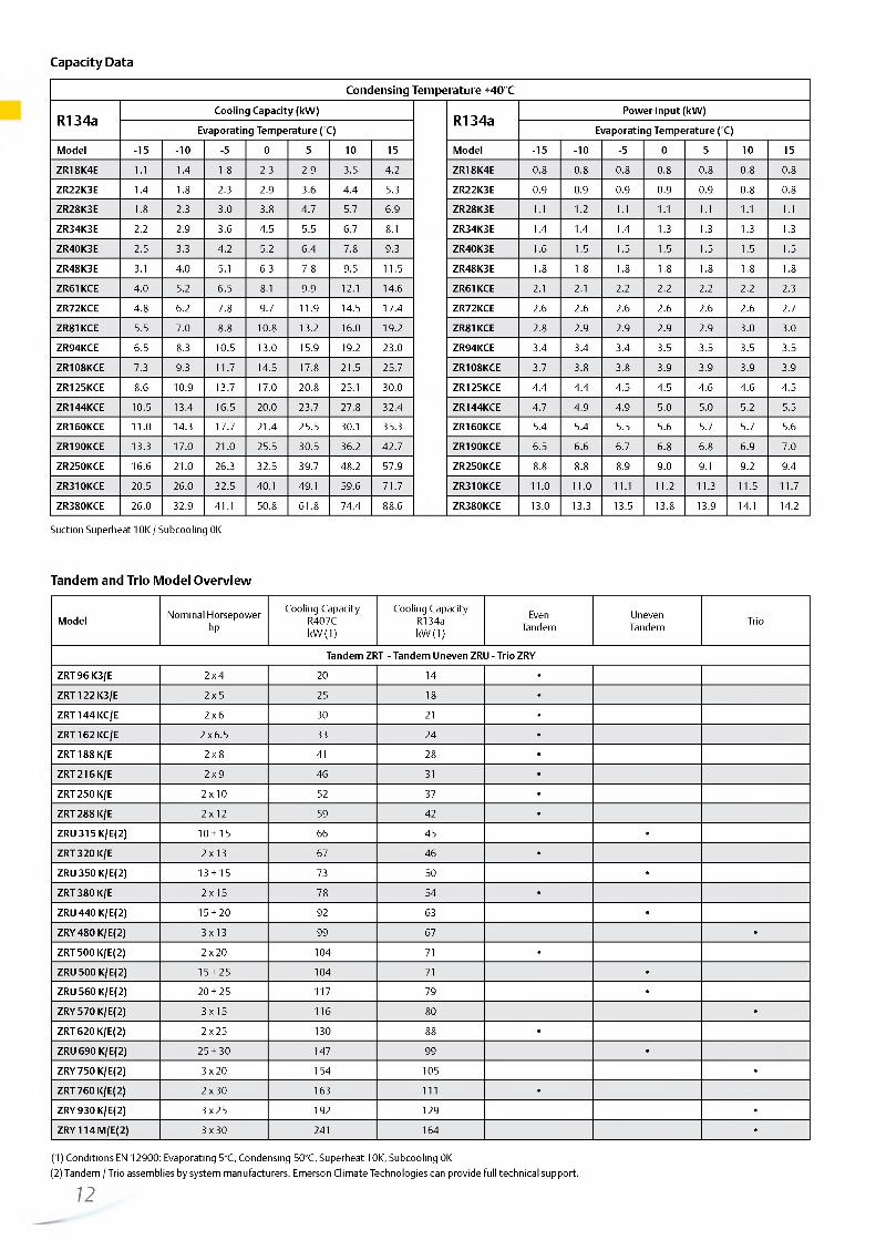
Capacity Data
Condensing Tem perature +40°C
R134aCooling Capacity (kW)
R134aPower Input (kW)
Evaporating Temperature (°C) Evaporating Temperature (°C)
Model -15 - 1 0 -5 0 5 1 0 15 Model -15 - 1 0 -5 0 5 10 15
ZR18K4E 1 .1 1.4 1.8 2.3 2.9 3.5 4.2 ZR18K4E 0.8 0.8 0.8 0.8 0.8 0.8 0.8
ZR22K3E 1.4 1.8 2.3 2.9 3.6 4.4 5.3 ZR22K3E 0.9 0.9 0.9 0.9 0.9 0.8 0.8
ZR28K3E 1.8 2.3 3.0 3.8 4.7 5.7 6.9 ZR28K3E 1 .1 1 .2 1 .1 1 . 1 1 .1 1 . 1 1 .1
ZR34K3E 2.2 2.9 3.6 4.5 5.5 6.7 8.1 ZR34K3E 1.4 1.4 1.4 1.3 1.3 1.3 1.3
ZR40K3E 2.5 3.3 4.2 5.2 6.4 7.8 9.3 ZR40K3E 1 .6 1.5 1.5 1.5 1.5 1.5 1.5
ZR48K3E 3.1 4.0 5.1 6.3 7.8 9.5 11.5 ZR48K3E 1.8 1 .8 1 .8 1 .8 1 .8 1 .8 1 .8
ZR61KCE 4.0 5.2 6.5 8.1 9.9 12 . 1 14.6 ZR61KCE 2.1 2.1 2.2 2 .2 2.2 2 .2 2.3
ZR72KCE 4.8 6.2 7.8 9.7 11.9 14.5 17.4 ZR72KCE 2.6 2.6 2.6 2.6 2.6 2.6 2.7
ZR81KCE 5.5 7.0 8.8 10 .8 13.2 16.0 19.2 ZR81KCE 2.8 2.9 2.9 2.9 2.9 3.0 3.0
ZR94KCE 6.5 8.3 10.5 13.0 15.9 19.2 23.0 ZR94KCE 3.4 3.4 3.4 3.5 3.5 3.5 3.5
ZR108KCE 7.3 9.3 11.7 14.5 17.8 21.5 25.7 ZR108KCE 3.7 3.8 3.8 3.9 3.9 3.9 3.9
ZR125KCE 8.6 10.9 13.7 17.0 20.8 25.1 30.0 ZR125KCE 4.4 4.4 4.5 4.5 4.6 4.6 4.5
ZR144KCE 10.5 13.4 16.5 20.0 23.7 27.8 32.4 ZR144KCE 4.7 4.9 4.9 5.0 5.0 5.2 5.5
ZR160KCE 1 1 . 0 14.3 17.7 21.4 25.5 30.1 35.3 ZR160KCE 5.4 5.4 5.5 5.6 5.7 5.7 5.6
ZR190KCE 13.3 17.0 2 1 . 0 25.5 30.5 36.2 42.7 ZR190KCE 6.5 6.6 6.7 6.8 6.8 6.9 7.0
ZR250KCE 16.6 2 1 . 0 26.3 32.5 39.7 48.2 57.9 ZR250KCE 8.8 8.8 8.9 9.0 9.1 9.2 9.4
ZR310KCE 20.5 26.0 32.5 40.1 49.1 59.6 71.7 ZR310KCE 1 1 . 0 1 1 . 0 1 1 . 1 1 1 . 2 11.3 11.5 11.7
ZR380KCE 26.0 32.9 41.1 50.8 61.8 74.4 88.6 ZR380KCE 13.0 13.3 13.5 13.8 13.9 14.1 14.2
Suction Superheat 10K / Subcooling 0K
Tandem and Trio Model Overview
Model Nominal Horsepower hp
Cooling Capacity R407C kW (1)
Cooling Capacity R134a kW (1)
EvenTandem
UnevenTandem Trio
Tandem ZRT - Tandem Uneven ZRU - Trio ZRY
ZRT 96 K3/E 2 x 4 20 14 •
ZRT 122 K3/E 2 x 5 25 18 •
ZRT 144 KC/E 2 x 6 30 21 •
ZRT 162 KC/E 2 x 6.5 33 24 •
ZRT 188 K/E 2 x 8 41 28 •
ZRT 216 K/E 2 x 9 46 31 •
ZRT 250 K/E 2 x 10 52 37 •
ZRT 288 K/E 2 x 1 2 59 42 •
ZRU 315 K/E(2) 10 + 15 66 45 •
ZRT 320 K/E 2 x 13 67 46 •
ZRU 350 K/E(2) 13 + 15 73 50 •
ZRT 380 K/E 2 x 15 78 54 •
ZRU 440 K/E(2) 15 + 20 92 63 •
ZRY 480 K/E(2) 3 x 13 99 67 •
ZRT 500 K/E(2) 2 x 20 104 71 •
ZRU 500 K/E(2) 15 + 25 104 71 •
ZRU 560 K/E(2) 20 + 25 117 79 •
ZRY 570 K/E(2) 3 x 15 116 80 •
ZRT 620 K/E(2) 2 x 25 130 88 •
ZRU 690 K/E(2) 25 + 30 147 99 •
ZRY 750 K/E(2) 3 x 20 154 105 •
ZRT 760 K/E(2) 2 x 30 163 1 1 1 •
ZRY 930 K/E(2) 3 x 25 192 129 •
ZRY 114 M/E(2) 3 x 30 241 164 •
(1) Conditions EN 12900: Evaporating 5°C, Condensing 50°C, Superheat 10K, Subcooling 0K(2) Tandem / Trio assemblies by system manufacturers. Emerson Climate Technologies can provide full technical support.
12

http://holodko.ru/

http://holodko.ru/
ZP Copeland Scroll™ Compressor Range for R410AZP Copeland Scroll compressors, for R410A, for comfort and process/precision cooling applications.
Emerson Climate Technologies has been the pioneer in launching the first complete line-up of R410A commercial scroll compressors. The combination of Copeland Scroll technology and the advantages of the R410A refrigerant enables system manufacturers (OEMs) to optimize the cost and efficiency of their systems.
ZP Copeland Scroll compressors are perfectly suitable for air cooled chiller systems up to 600kW (720kW if water cooled) featuring high comfort and superior seasonal efficiency (ESEER). Whether used in stand-alone, tandem or trio configurations, the broad ZP Copeland Scroll line-up meets today's market requirements with unmatched flexibility, efficiency and proven reliability.
The second generation of Copeland™ commercial scrolls for R410A now features the new ZP236K (20hp) & ZP296K (25hp) with CoreSense™ Communications: this added feature unlocks advanced diagnostics, protection and communication in Copeland compressors and sends data to the main system controller via modbus RS485.
ZP Scroll Compressor
ZP Scroll Compressor Line-up
Tandem • • « ■ • • • • • • • • • • • • •
Trio • • • • • • • • • • •
kW Cooling I I I I I I I I I I I I I I I I I I I I I I I I I I I I I I I I0 10 20 30 40 50 60 70 80 90 100 110120130140150 160170 180190 200 210 220 230 240250 260270 280290 300 310
Conditions EN12900: Evaporating 5°C, Condensing 50°C, Superheat 10K, Subcooling 0K
Features and Benefits
• Copeland qualified tandem and trio (now also uneven) configurations for superior seasonal efficiency (ESEER and SCOP)
• Copeland Scroll axial and radial compliance for superior reliability and efficiency
• Extended 5K operating envelope suitable for HP applications• Low TEWI (Total Equivalent Warming Impact)• Wide scroll line-up for R410A• Low sound and vibration level• Low oil circulation rate
Maximum Allowable Pressure (PS)
• ZP24 to ZP91:Low Side PS 28 bar(g) / High Side PS 43 bar(g)
• ZP90 to ZP485:Low Side PS 29.5 bar(g) / High Side PS 45 bar(g)
14
Operating Envelope R410A
Evaporating Temperature °C 10K Superheat
ZP24-91 - - - ZP90-137 ZP 154-485
__—

http://holodko.ru/
Technical Overview
R410ANo
min
alhp
Capa
city
(kW
) POC
Disp
lace
men
t(m
3/h)
Stub
Suct
ion
(inch
)
Stub
Disc
harg
e(in
ch)
Oil
Qua
ntity
(l)
Length/Width/Heigth(mm)
NetWeight
(kg)
Motor Version/ Code
Maximum Operating Current (A)
Locked Rotor Current (A)
Sound Pressure
@1 m (dBA)
1 Ph* 3Ph** 1 Ph* 3
Ph** 1 Ph* 3Ph**
ZP24KSE 1.9 5.1 2.8 3.9 3/4 1 / 2 0.74 242/242/407 22 PFZ TFM 13 5 60 28 55
ZP29KSE 2.2 6.1 2.9 4.8 3/4 1 / 2 0.74 242/242/407 23 PFZ TFM 16 6 67 38 55
ZP31KSE 3.0 6.5 2.8 5.0 3/4 1 / 2 0.74 242/242/388 23 PFZ TFM 17 6 67 38 55
ZP36KSE 2.6 7.9 3.0 6.0 7/8 1 / 2 1.25 242/242/421 30 PFZ TFM 2 2 7 98 46 57
ZP42KSE 3.4 9.0 2.9 6.9 7/8 1 / 2 1.25 242/242/421 31 PFZ TFM 26 8 128 43 57
ZP54KSE 4.6 1 1 . 6 3.0 8.9 7/8 1 / 2 1.24 242/242/422 34 PFZ TFM 31 1 0 115 51 69
ZP61KCE 5.0 13.1 3.0 10 .1 7/8 1 / 2 1.6 6 245/249/440 40 TFD 1 2 64 60
ZP72KCE 6.0 15.3 3.0 11.7 7/8 1 / 2 1.77 245/249/440 40 TFD 15 75 64
ZP83KCE 6.5 17.7 3.1 13.4 7/8 1 / 2 1.77 241/247/440 40 TFD 15 1 0 1 61
ZP91KCE 7.5 19.3 3.1 14.7 7/8 3/4 1.77 243/248/443 41 TFD 16 1 0 1 61
ZP90KCE 7.5 19.4 3.1 14.6 1 1 /8 7/8 2.65 264/284/476 57 TFD 16 95 61
ZP103KCE 9.0 22.4 3.2 16.7 1 3/8 7/8 3.38 264/284/533 59 TFD 21 1 1 1 63
ZP120KCE 10 .0 26.6 3.2 19.7 1 3/8 7/8 3.38 264/284/533 61 TFD 2 2 118 63
ZP137KCE 1 2 . 0 29.9 3.2 22.1 1 3/8 7/8 3.38 264/284/533 61 TFD 25 118 64
ZP154KCE 13.0 33.5 3.2 24.8 1 3/8 7/8 3.38 264/284/552 65 TFD 31 140 65
ZP182KCE 15.0 39.6 3.2 29.1 1 3/8 7/8 3.38 264/284/552 66 TFD 34 174 66
ZP235KCE 20.0 50.6 3.2 37.8 1 5/8 1 3/8 4.70 432/376/717 140 TWD 40 225 71
ZP236KCE 20.0 50.9 3.2 37.8 1 5/8 1 1 /8 4.30 383/391/694 127 TED 41 229 71
ZP295KCE 25.0 63.5 3.2 46.7 1 5/8 1 3/8 6.80 448/392/725 160 TWD 48 272 74
ZP296KCE 25.0 63.2 3.2 46.5 1 5/8 1 1 /8 4.30 383/391/694 132 TED 51 320 74
ZP385KCE 30.0 82.4 3.2 60.8 1 5/8 1 3/8 6.30 448/392/715 178 TWD 65 310 74
ZP485KCE 40.0 105.0 3.2 77.3 1 5/8 1 3/8 6.30 448/392/756 190 TWD 82 408 78
Conditions EN12900 : Evaporating 5°C, Condensing 50°C, Superheat 10K, Subcooling 0K
* 1 Ph: 230V/ 50Hz ** 3 Ph: 380-420V/ 50Hz*** @ 1 m: sound pressure level at 1 m distance from the compressor, free field condition
15

http://holodko.ru/
Capacity Data
Condensing Tem perature +40°C
R410ACooling Capacity (kW )
R410APow er Input (kW )
Evaporating Tem perature <°C) Evaporating Tem perature °C)
Model -15 - 1 0 -5 0 5 1 0 15 Model -15 - 1 0 -5 0 5 1 0 15
ZP24KSE 2 . 2 3.0 3.9 4.9 5.9 7.1 ZP24KSE 1.5 1.5 1.4 1.4 1.4 1.3
ZP29KSE 2.9 3.9 4.9 6 .0 7.3 8 .6 ZP29KSE 1 . 8 1 . 8 1.7 1.7 1.7 1 . 6
ZP31KSE 3.2 4.1 5.2 6.3 7.6 9.1 ZP31KSE 1.9 1.9 1.9 1 . 8 1 . 8 1 . 8
ZP36KSE 4.1 5.1 6.3 7.7 9.2 1 1 . 0 ZP36KSE 2 . 2 2 . 1 2 . 1 2 . 1 2 . 1 2 . 1
ZP42KSE 4.4 5.7 7.1 8.7 10.5 12.5 ZP42KSE 2.4 2.4 2.4 2.4 2.3 2.3
ZP54KSE 6 .0 7.5 9.3 11.3 13.5 16.0 ZP54KSE 3.1 3.1 3.0 3.0 2.9 2.9
ZP61KCE 6.5 8.3 10.4 1 2 . 6 15.2 18.1 ZP61KCE 3.7 3.7 3.6 3.5 3.5 3.4
ZP72KCE 8 . 2 1 0 . 1 12.3 14.8 17.7 20.9 ZP72KCE 4.0 4.0 4.0 4.0 4.1 4.1
ZP83KCE 9.4 1 1 . 6 14.2 17.1 20.4 24.2 ZP83KCE 4.5 4.5 4.5 4.6 4.6 4.7
ZP91KCE 1 0 . 2 1 2 . 6 15.4 18.6 2 2 . 2 26.3 ZP91KCE 4.9 4.9 4.9 5.0 5.0 5.0
ZP90KCE 10.4 1 2 . 8 15.6 18.8 22.4 26.5 31.1 ZP90KCE 5.0 5.0 5.0 5.0 5.1 5.2 5.3
ZP103KCE 11.7 14.6 17.9 2 1 . 6 25.8 30.5 35.7 ZP103KCE 5.7 5.7 5.6 5.6 5.7 5.8 5.9
ZP120KCE 14.0 17.5 21.4 25.8 30.8 36.4 42.5 ZP120KCE 6 .6 6.6 6.5 6.5 6.5 6 .6 6.7
ZP137KCE 15.9 19.9 24.2 29.2 34.8 41.2 48.3 ZP137KCE 7.4 7.4 7.4 7.4 7.4 7.4 7.5
ZP154KCE 18.2 22.3 27.1 32.6 38.9 46.1 54.3 ZP154KCE 8 . 1 8 . 2 8 . 2 8.3 8.3 8.5 8 .8
ZP182KCE 21.4 26.3 32.0 38.4 45.6 53.9 63.3 ZP182KCE 9.5 9.7 9.9 1 0 . 0 1 0 . 1 1 0 . 1 1 0 . 0
ZP235KCE 26.5 32.9 40.3 48.8 58.6 69.7 82.3 ZP235KCE 12.5 1 2 . 6 12.7 1 2 . 8 13.0 13.2 13.5
ZP236KCE 22.7 33.6 40.7 48.9 58.2 68.9 81.0 ZP236KCE 12.7 1 2 . 8 12.9 13.0 13.1 13.3 13.5
ZP295KCE 34.2 41.9 50.9 61.3 73.3 86.9 102.5 ZP295KCE 15.8 16.0 16.1 16.2 16.4 16.6 16.8
ZP296KCE 33.3 41.3 40.4 60.7 72.3 85.3 1 0 0 . 0 ZP296KCE 16.0 15.9 15.9 16.0 16.3 16.7 17.4
ZP385KCE 43.7 53.9 65.8 79.5 95.2 113.0 133.5 ZP385KCE 20.3 20.4 20.5 20.7 20.9 21.3 21.7
ZP485KCE 57.5 70.0 84.7 1 0 1 . 6 1 2 1 . 0 143.0 168.0 ZP485KCE 24.9 25.3 25.8 26.3 27.0 27.8 28.8
Suction Superheat 10K / Subcooling 0K
16—

http://holodko.ru/
Tandem and Trio Model Overview
ModelNominal
Horsepowerhp
Cooling CapacitykW (1)
EvenTandem
UnevenTandem Trio Uneven
Trio
Tandem ZPT - Tandem Uneven ZPU - Trio ZPY - Uneven Trio ZPM
ZPT 72 K/E(2) 2 x 3 16 •
ZPT 84 K/E(2) 2 x 3,5 18 •
ZPT 108 K/E(2) 2 x 4 23 •
ZPT 122 K/E(2) 2 x 5 26 •
ZPT 144 K/E(2) 2 x 6 31 •
ZPT 166 K/E(2) 2 x 6,5 35 •
ZPT 180 K/E(2) 2 x 8 39 •
ZPT 182 K/E(2) 2 x 8 39 •
ZPT 206 K/E(2) 2 x 9 45 •
ZPT 240 K/E(2) 2 x 1 0 53 •
ZPT 274 K/E(2) 2 x 1 2 60 •
ZPU 302 K/E(2) 10 + 15 6 6 •
ZPT 308K/E(2) 2 x 13 67 •
ZPY 309K/E(2) 3 x 9 6 6 •
ZPU 336 K/E(2) 13 + 15 73 •
ZPY 360 K/E(2) 3 x 10 79 •
ZPT 364 K/E(2) 2 x 15 79 •
ZPY 411K/E(2) 3 x 12 8 8 •
ZPU 417 K/E(2) 15 + 20 90 •
ZPU418K/E(2) 20 + 15 90 •
ZPY 462 K/E(2) 3 x 13 99 •
ZPT 470 K/E(2) 2 x 2 0 1 0 1 •
ZPT472K/E(2) 2 x 2 0 1 0 1 •
ZPU 477 K/E(2) 15 + 25 103 •
ZPU 530 K/E(2) 20 + 25 114 •
ZPU 532K/E(2) 2 x 2 0 1 0 1 •
ZPY 546 K/E(2) 3 x 15 117 •
ZPT 590 K/E(2) 2 x 25 127 •
ZPT 592K/E(2) 2 x 25 125 •
ZPU 680 K/E(2) 25 + 30 146 •
ZPU 681K/E(2) 30 + 25 144 •
ZPY 705 K/E(2) 3 x 20 150 •
ZPY 708K/E(2) 3 x 20 150 •
ZPT 770 K/E(2) 2 x 30 165 •
ZPU 870 K/E(2) 30 + 40 187 •
ZPY 885 K/E(2) 3 x 25 188 •
ZPY 8 8 8 K/E(2) 3 x 25 187 •
ZPT 970 K/E(2) 2 x 40 209 •
ZPY 115 M/E(2) 3 x 30 243 •
ZPM 125 M/E(2) 30 + 30 + 40 265 •
ZPM 135 M/E(2) 30 + 40 + 40 287 •
ZPY 145 M/E(2) 40 + 40 + 40 309 •
(1) Conditions EN 12900: Evaporating 5°C, Condensing 50°C, Superheat 10K, Subcooling 0K(2) Tandem / Trio assemblies by system manufacturers. Emerson Climate Technologies can provide full technical support.
17

http://holodko.ru/
Stepless capacity modulation in air conditioning applications:Flexible solution for R407C and R410A.
In many cooling and heating systems, the load and the operating conditions vary over a wide range thus requiring the use of capacity modulation. Digital Scroll assures stepless modulation down to 10% of the nominal capacity, enabling precise temperature control, superior comfort and energy saving.
ZPD & ZRD Copeland Digital Scroll™ Compressor Range
Digital Scroll compressors are the preferred choice for process cooling, refrigeration racks, condensing units, VRF, rooftop and air handling unit systems.
ZPD Digital Scroll Compressor Line-up R410A
ZPD & ZRD Copeland Digital Scroll Compressor
ZPD (3Ph) • • • • • • • • • • • •
Tandem • • • • • • • • • •
kW Cooling5 10 15 20 25 30 35 40 45 50 55 60 65 70 75 80
ZRD Digital Scroll Compressor Line-up R407C
Conditions EN12900: Evaporating 5°C, Condensing 50°C, Superheat 10K, Subcooling 0K
Features and Benefits
• Wide modulation range from 10% to 100% for immediate load adjustment, close temperature comfort,optimal comfort
• No complex electronics, a quasi-drop-in solution for fast time to market, no EMI/EMC problems, easy installation and maintenance
• No impact on system mechanical balance: no vibration and resonance phenomenon, no frame / piping redesign necessary
Operating Envelope R410A/R407C
Evaporating Temperature °C R410A - 10K Superheat
— ZPD 34-91 — ZPD 103-182
18
Maximum Allowable Pressure (PS)
• Digital ZRD42 to ZRD81:Low Side PS 20bar(g) / High Side PS 29.5 bar(g)
• Digital ZRD94 to ZRD125:Low Side PS 20bar(g) / High Side PS 32 bar(g)
• Digital ZPD34 to ZPD91:Low Side PS 28 bar(g) / High Side PS 43 bar(g)
• Digital ZPD103 to ZPD182:Low Side PS 29.5 bar(g) / High Side PS 45 bar(g)
Evaporating Temperature °C R407C - 10K Superheat
— ZRD 42-81 — — ZRD 94-125
__—

http://holodko.ru/
Technical Overview
R410ANo
min
alhp
Capa
city
(kW
) POC
Disp
lace
men
t(m
3/h)
Stub
Suct
ion
(inch
)
Stub
Disc
harg
e (in
ch)
Oil Q
uant
ity
(l)
Length/Width/Heigth
(mm)
NetWeight
(kg)
Motor Version/ Code
Maximum Operating Current (A)
Locked Rotor Current (A)
Sound Pressure @1 m (dBA)3 Ph** 3 Ph** 3 Ph**
ZPD34KSE 3.0 7.3 2.8 5.7 7/8 1 / 2 1.24 243/243/448 31 TFM 1 2 64 66
ZPD42KSE 3.5 9.1 3.0 6.9 7/8 1 / 2 1.24 243/243/464 31 TFM 8 52 66
ZPD54KSE 4.5 11.5 3.0 8.9 7/8 1 / 2 1.24 236/236/479 35 TFM 10 62 67
ZPD61KCE 5.0 13.2 2.9 10 .1 7/8 1 / 2 1.89 241/246/484 41 TFD 1 2 64 63
ZPD72KCE 5.0 15.2 2.9 1 1 . 6 7/8 1 / 2 1.89 241/246/484 40 TFD 15 75 67
ZPD83KCE 6.0 17.7 3.0 13.4 7/8 1 / 2 1.77 241/246/484 40 TFD 16 10 1 64
ZPD91KCE 7.5 19.2 3.1 14.7 7/8 3/4 1.80 241/246/484 40 TFD 16 10 1 69
ZPD103KCE 9.0 22.4 3.2 16.7 1 3/8 7/8 3.25 293/285/533 61 TFD 21 1 1 1 63
ZPD120KCE 10 .0 26.3 3.2 19.7 1 3/8 7/8 3.25 285/293/533 62 TFD 22 118 63
ZPD137KCE 12 . 0 29.5 3.1 22 .1 1 3/8 7/8 3.25 285/293/533 62 TFD 25 118 63
ZPD154KCE 13.0 33.1 3.1 24.8 1 3/8 7/8 3.25 326/295/552 65 TWD 27 140 66
ZPD182KCE 15.0 39.0 3.1 29.0 1 3/8 7/8 3.25 326/295/552 67 TWD 34 173 68
Conditions EN12900 R410A: Evaporating 5°C, Condensing 50°C, Superheat 10K, Subcooling 0K
** 3 Ph: 380-420V/ 50Hz*** @ 1 m: sound pressure level at 1 m distance from the compressor, free field condition
R407C
Nom
inal
hp
Capa
city
(kW
) POC
Disp
lace
men
t(m
3/h)
Stub
Suct
ion
(inch
)
Stub
Disc
harg
e (in
ch)
Oil Q
uant
ity
(l)
Length/Width/Heigth
(mm)
NetWeight
(kg)
Motor Version/ Code
Maximum Operating Current (A)
Locked Rotor Current (A)
Sound Pressure @1 m (dBA) ***
3 Ph** 3 Ph** 3 Ph**
ZRD42KCE 3.5 8.9 2.9 9.9 3/4 1 / 2 1.24 241/241/462 31 TFD 7 46 60
ZRD48KCE 4.0 10.5 3.0 11.4 7/8 1 / 2 1.36 241/241/465 32 TFD 10 48 64
ZRD61KCE 5.0 12.5 3.0 14.3 7/8 1 / 2 1.89 241/246/481 38 TFD 9.6 64 65
ZRD72KCE 6.0 14.3 2.9 17.0 7/8 3/4 1.89 241/246/481 40 TFD 13 74 63
ZRD81KCE 6.0 17.0 3.1 18.7 7/8 3/4 1.89 241/246/481 41 TFD 15 1 0 0 67
ZRD94KCE 7.5 2 1 . 0 3.3 22 .1 1 1 /8 7/8 2.51 293/285/476 58 TFD 16 95 64
ZRD125KCE 10 .0 27.7 3.3 28.8 1 3/8 7/8 3.25 293/285/533 61 TFD 20 118 64
Conditions EN12900 R407C: Evaporating 5°C, Condensing 50°C, Superheat 10K, Subcooling 0K
** 3 Ph: 380-420V/ 50Hz*** @ 1 m: sound pressure level at 1 m distance from the compressor, free field condition
19

http://holodko.ru/
Capacity Data
Condensing Tem perature +40°C
R410ACooling Capacity (kW )
R410APow er Input (kW )
Evaporating Tem perature (°C) Evaporating Tem perature (°C)
Model -15 - 1 0 -5 0 5 1 0 15 Model -15 - 1 0 -5 0 5 1 0 15
ZPD34KSE 3.9 5.0 6 . 2 7.6 9.2 1 1 . 0 ZPD34KSE 2 . 1 2 . 1 2 . 1 2 . 0 2 . 0 2 . 0
ZPD42KSE 4.8 5.9 7.3 8.8 1 0 . 6 1 2 . 6 ZPD42KSE 2.3 2.3 2.4 2.4 2.4 2.3
ZPD54KSE 6.5 7.9 9.5 11.4 13.5 16.0 ZPD54KSE 3.1 3.1 3.1 3.0 3.0 3.0
ZPD61KCE 6.9 8 .6 10.5 12.7 15.3 18.2 ZPD61KCE 3.3 3.4 3.5 3.5 3.6 3.6
ZPD72KCE 8 . 2 1 0 . 1 12.3 14.8 17.6 20.9 ZPD72KCE 3.9 4.0 4.1 4.1 4.2 4.2
ZPD83KCE 9.7 11.9 14.4 17.2 20.5 24.1 ZPD83KCE 4.5 4.6 4.7 4.7 4.8 4.9
ZPD91KCE 1 0 . 1 1 2 . 6 15.3 18.5 2 2 . 1 26.2 30.9 ZPD91KCE 4.9 5.0 5.0 5.0 5.1 5.0 5.0
ZPD103KCE 11.7 14.6 17.9 2 1 . 6 25.8 30.5 35.7 ZPD103KCE 5.7 5.7 5.6 5.6 5.7 5.8 5.9
ZPD120KCE 13.8 17.3 2 1 . 2 25.6 30.6 36.1 42.2 ZPD120KCE 6.7 6.7 6 .6 6.6 6.6 6.7 6 .8
ZPD137KCE 15.5 19.4 23.7 28.7 34.2 40.3 47.2 ZPD137KCE 7.5 7.5 7.5 7.4 7.4 7.5 7.6
ZPD154KCE 17.8 2 2 . 0 26.6 31.9 38.0 45.0 53.0 ZPD154KCE 8 . 2 8.3 8.4 8.5 8 .6 8.7 8.9
ZPD182KCE 22.3 26.8 32.0 37.9 44.6 52.5 61.6 ZPD182KCE 9.8 9.9 1 0 . 0 1 0 . 1 1 0 . 2 10.4 10.5
Suction Superheat 10K / Subcooling 0K
Condensing Tem perature +40°C
R407CCooling Capacity (kW )
R407CPow er Input (kW )
Evaporating Tem perature [°C) Evaporating Tem perature [°C)
Model -15 - 1 0 -5 0 5 1 0 15 Model -15 - 1 0 -5 0 5 1 0 15
ZRD42KCE 4.3 5.4 6.7 8.3 1 0 . 1 1 2 . 2 14.6 ZRD42KCE 2 . 0 2 . 1 2 . 1 2 . 2 2 . 2 2.3 2.3
ZRD48KCE 4.9 6.4 8.0 1 0 . 0 12.3 15.0 18.1 ZRD48KCE 2.5 2 . 6 2 . 6 2.7 2.7 2 . 8 2.9
ZRD61KCE 6 . 1 7.7 9.5 11.7 14.2 17.3 2 1 . 0 ZRD61KCE 3.0 3.1 3.2 3.4 3.4 3.4 3.3
ZRD72KCE 3.5 6 .0 8.9 12.3 16.2 2 0 . 6 25.6 ZRD72KCE 3.5 3.6 3.7 3.8 4.0 4.1 4.3
ZRD81KCE 8 .0 1 0 . 2 1 2 . 8 15.8 19.2 23.2 27.7 ZRD81KCE 4.3 4.4 4.4 4.5 4.6 4.7 4.8
ZRD94KCE 1 0 . 0 12.7 16.0 19.8 24.1 28.9 34.5 ZRD94KCE 5.0 5.1 5.1 5.1 5.1 5.2 5.3
ZRD125KCE 13.2 16.9 21.3 26.3 31.7 37.6 43.7 ZRD125KCE 6.5 6 .6 6.6 6.7 6 .8 6.9 7.1
Suction Superheat 10K / Subcooling 0K
20—

http://holodko.ru/

http://holodko.ru/
ZH Copeland Scroll™ Compressor Range
ZH Copeland Scroll Compressor RangeThe ZH compressor range is optimized for reversible and heat pump applications. In addition to the existing R407C range, a complete new range optimized for R410A has been developed. Both ranges are based on three platform sizes and cover a capacity of 4kW to 38kW.
ZH heating compressors have been optimized for reversible heating systems, they deliver higher capacity and efficiency at low evaporating (heat source) temperatures and are therefore better adapted to heating requirements than standard air conditioning compressors. Due to their larger operating map they also require less additional heating (electrical or gas) to cover the full heating demand on the coldest days and therefore further improve the system seasonal efficiency.
ZH Scroll Compressors with Enhanced Vapor InjectionZH heating compressors with Enhanced Vapor Injection have been further optimized to ensure best-in-class performances in dedicated heating applications. This technology allows replacement of traditional boilers in new building and retrofit applications, without the need of substituting existing heating elements in the building.
ZH Copeland Scroll heating compressors with Enhanced Vapor Injection have an additional port to inject vapor within the compression process. This improves system performances by increasing the heating capacity for a given compressor displacement. Additional benefits are the reduction of the gas discharge temperature and the extension of the operating envelope which enable the production of high temperature water at all working conditions.
ZHI heating compressors reach the same high standards of durability and reliability as other Copeland Scroll compressors. This includes the ability to handle relatively large amounts of liquid, which is known to damage or cause compressor failures. Fewer moving parts, robust running gear and low vibration due to balanced compression mechanism make the ZH range of Copeland Scroll compressors the most reliable solution available in the heat pump market.
Enhanced Vapor Injection: System Design
EV
22
ZH Scroll Compressors
ZH Nomenclature Guidelines
ZH **K4EQualified for R407C/R134aWithout Enhanced Vapor Injection - ** capacity in Btu/h
ZH **KVEQualified for R407C onlyEnhanced Vapor Injection - ** capacity in kW
ZH**K1PQualified for R410A onlyWithout Enhanced Vapor Injection - ** capacity in kW
ZH! **K 1PQualified for R410A onlyEnhanced Vapor Injection - ** capacity in kW
Enhanced Vapor Injection: Enthalpy Diagram

http://holodko.ru/
ZH / ZH*KVE R407C Compressor Line-up
• •Single Phase
• • M • • •• ZH*KVE with Enh. Vapor Inj.• ZH without Enh. Vapor Inj.
• • • • • • •Three Phase
• • • • • • • • • • • •
0 5 10 15 20 251
30l l l
35 40 45l
50
Conditions Heating kW @ (-7/50)
ZH*P / ZHI*P R410A Compressor Line-up
• •Single Phase
• • • • •• ZHI*P with Enh. Vapor Inj.• ZH*P without Enh. Vapor Inj.
• • • • • • • • • •Three Phase
• • • • • • •in development
0 5 10 15 20 251
30i i i
35 40 45i
50
Conditions Heating kW @ (-7/50)
Features and Benefits
Copeland Scroll axial and radial compliance for high reliabilityHigh efficiency and increased heating capacityHigh water temperature for all applicationsLow sound and low vibration levelTandem combination for superior seasonal efficiencyEnhanced Vapor Injection technology for best seasonalefficiency
Maximum Allowable Pressure (PS)
ZH (I)**K1P:Low Side PS 28 bar(g) / High Side PS 45 bar(g)
ZH12K4E to ZH45K4E:Low Side PS 20 bar(g) / High Side PS 32 bar(g)
ZH56K4E to ZH11M4E:Low Side PS 22.6 bar(g) / High Side PS 32 bar(g)
ZH09KVE to ZH18KVE:Low Side PS 20 bar(g) / High Side PS 32 bar(g)
ZH24KVE to ZH48KVE:Low Side PS 22.6 bar(g) / High Side PS 32 bar(g)
Operating Envelope R410A Heating Operating Envelope R407C Heating
cO'TDCO
Evaporating Tem perature °C
------ ZH*P without Enh. Vapor Inj.------ ZH*P Transient------ ZHI*P with Enh. Vapor Inj.------ ZHI*P Transient------ Wet Injection
Refer to Em erson’s Select 7 .7 selection software fo r individual model operating envelopes and other refrigerants.
neTDno
Evaporating Tem perature °C
---- ZH without Enh. Vapor Inj.----ZH Transient---- ZH*KVE with Enh. Vapor Inj.- - - ZH*KVETransient ---- Wet Injection
23

http://holodko.ru/
Technical Overview
R407CNo
min
alhp
Capa
city
(kW
) POC
Disp
lace
men
t(m
3/h)
Stub
Suct
ion
(inch
)
Stub
Disc
harg
e (in
ch)
Oil Q
uant
ity
(l)
Length/Width/Heigth
(mm)
NetWeight
(kg)
Motor Version/ Code
Maximum Operating Current (A)
Locked Rotor Current (A)
Sound Pressure
@1 m (dBA)
1 Ph* 3 Ph** 1 Ph* 3 Ph** 1 Ph* 3 Ph**
ZH12K4E 1.7 3.7 3.0 4.7 3/4 1 / 2 0.7 272/193/403 21 PFZ 10 44 53
ZH15K4E 2.0 4.8 2.9 5.9 3/4 1 / 2 1.3 243/242/364 23 PFJ TFD 15 5 58 26 60
ZH19K4E 2.5 5.9 3.0 7.3 3/4 1 / 2 1.5 243/242/386 25 PFJ TFD 17 6 74 32 60
ZH21K4E 3.0 6.5 3.1 8.0 3/4 1 / 2 1.5 243/242/406 27 PFJ TFD 16 5 76 32 59
ZH26K4E 3.5 8.2 3.1 10 .0 3/4 1 / 2 3.1 243/242/419 28 PFJ TFD 20 7 97 46 63
ZH30K4E 4.0 9.5 3.1 11.7 7/8 1 / 2 1.9 247/241/438 38 PFJ TFD 25 8 108 52 62
ZH38K4E 5.0 11.7 3.2 14.4 7/8 1 / 2 1.9 247/241/438 38 PFZ TFD 31 10 150 64 63
ZH45K4E 6.0 14.0 3.2 17.1 7/8 1 / 2 1.9 250/246/450 36 TFD 1 2 74 64
ZH56K4E 7.5 17.4 3.1 20.9 1 - 3/8 7/8 4.0 357/321/538 93 TWD 17 99 69
ZH75K4E 10 .0 24.2 3.2 28.8 1 - 3/8 7/8 4.0 357/321/538 93 TWD 21 127 70
ZH92K4E 13.0 30.7 3.3 35.6 1 - 3/8 7/8 4.1 357/321/545 95 TWD 25 167 72
ZH11M4E 15.0 37.0 3.3 42.8 /8 7/8 4.1 357/321/592 1 1 2 TWD 32 198 72
ZH09KVE 3.0 8.2 3.3 8.0 3/4 1 / 2 1.5 243/243/406 30 PFZ TFD 21 7 97 40 62
ZH13KVE 4.0 1 1 . 8 3.4 11.7 7/8 1 / 2 1.9 244/241/438 38 PFZ TFD 30 10 160 64 65
ZH18KVE 6.0 16.7 3.4 17.1 7/8 1 / 2 1.9 244/241/438 41 TFD 14 10 1 67
ZH24KVE 7.5 21.3 3.3 20.9 1 - 3/8 7/8 4.0 368/321/525 93 TWD 18 99 73
ZH33KVE 10 .0 29.5 3.4 29.0 1 - 3/8 7/8 4.0 368/321/525 93 TWD 24 127 73
ZH40KVE 13.0 37.0 3.4 35.5 1 - 3/8 7/8 4.1 368/321/532 103 TWD 30 167 73
ZH48KVE 15.0 44.7 3.4 42.8 /8 7/8 4.1 368/323/579 1 1 2 TWD 36 198 76
Conditions Evaporating -7°C, Condensing 50°C, Superheat 5K, Subcooling 4K
* 1 Ph: 230V/ 50Hz ** 3 Ph: 380-420V/ 50Hz*** @ 1 m: sound pressure level at 1 m distance from the compressor, free field condition
R410A
Nom
inal
hp
Capa
city
(kW
)
COP
Disp
lace
men
t(m
3/h)
Stub
Sucti
on
(inch
)
Stub
Disc
harg
e (in
ch)
Oil Q
uant
ity
(l)
Length/Width/Heigth(mm)
NetWeight
(kg)
Motor Version/ Code
Maximum Operating Current (A)
Locked Rotor Current (A) Sound
Pressure @1 m (dBA)
1 Ph* 3 Ph** 1 Ph* 3 Ph** 1 Ph* 3 Ph**
ZH04 K1P 1.8 4.2 2.8 3.4 3/4 1 / 2 0.7 229/198/388 22 PFZ TFM 9 5 50 28 62
ZH05 K1P 2.0 5.0 2.8 4.0 3/4 1 / 2 0.7 242/242/407 22 PFZ TFM 13 5 60 28 62
ZH06 K1P 2.7 6.6 2.9 5.1 7/8 1 / 2 1 .2 242/242/422 31 PFZ TFM 17 6 83 44 62
ZH09 K1P 3.5 9.0 3.1 6.9 7/8 1 / 2 1 .2 242/242/422 33 PFZ TFM 23 7 108 52 62
ZH12 K1P 4.5 11.7 3.1 8.9 7/8 1 / 2 1 .2 242/242/422 35 PFZ TFM 28 10 130 62 65
ZH15 K1P 5.0 15.1 3.1 11.7 7/8 1 / 2 1.9 245/249/455 39 TFM 13 75 67
ZH19 K1P 6.5 18.5 3.1 14.8 7/8 3/4 1.9 229/198/388 39 TFM 17 67
ZHI08 K1P 2.8 8.2 3.1 5.1 7/8 1 / 2 1 .2 229/246/418 31 PFZ TFM 19 6 108 43 63
ZHI11 K1P 3.6 10.8 3.2 6.9 7/8 1 / 2 1 .2 2428/242/421 31 PFZ TFM 25 9 130 52 65
ZHI14 K1P 4.6 13.9 3.3 8.9 7/8 1 / 2 1 .2 2428/242/421 34 TFM 1 1 70 65
ZHI18 K1P 5.0 17.9 3.4 11.7 7/8 1 / 2 1.9 249/245/455 41 TFM 15 67
ZHI23 K1P 6.5 22.8 3.4 14.8 7/8 3/4 1.9 249/245/455 41 TFM 19 67
Conditions Evaporating -7°C, Condensing 50°C, Superheat 5K, Subcooling 4K
* 1 Ph: 230V/ 50Hz ** 3 Ph: 380-420V/ 50Hz*** @ 1 m: sound pressure level at 1 m distance from the compressor, free field condition
24

http://holodko.ru/
Capacity Data
Condensing Tem perature +50°C
R407CHeating Capacity (kW )
R407CPow er Input (kW )
Evaporating tem perature <°C) Evaporating tem perature <°C)
Model -30 -15 - 1 0 -5 0 5 15 Model -30 -15 - 1 0 -5 0 5 15
ZH12K4E n.a. 2 . 8 3.3 3.9 4.6 5.4 7.5 ZH12K4E n.a. 1 . 2 1 . 2 1.3 1.3 1.3 1.4
ZH15K4E n.a. 3.7 4.3 5.1 6 .0 7.0 9.4 ZH15K4E n.a. 1.5 1 . 6 1 . 6 1.7 1.7 1 . 8
ZH19K4E n.a. 4.5 5.3 6 . 2 7.3 8 .6 11.7 ZH19K4E n.a. 1.9 1.9 2 . 0 2 . 1 2 . 1 2 . 2
ZH21K4E n.a. 5.1 5.9 6.9 8 .1 9.6 13.2 ZH21K4E n.a. 2 . 0 2 . 1 2 . 1 2 . 2 2.3 2.4
ZH26K4E n.a. 6.3 7.4 8.7 10.3 1 2 . 1 16.5 ZH26K4E n.a. 2.5 2 . 6 2.7 2.7 2 . 8 3.0
ZH30K4E n.a. 7.3 8 .6 1 0 . 1 11.9 14.0 19.2 ZH30K4E n.a. 2.9 3.0 3.1 3.2 3.3 3.4
ZH38K4E n.a. 9.0 1 0 . 6 12.5 14.6 17.2 23.4 ZH38K4E n.a. 3.5 3.6 3.8 3.9 4.0 4.2
ZH45K4E n.a. 1 0 . 8 12.7 14.9 17.4 20.3 27.2 ZH45K4E n.a. 4.2 4.3 4.5 4.6 4.7 5.1
ZH56K4E n.a. 13.4 15.8 18.6 2 1 . 8 25.5 34.1 ZH56K4E n.a. 5.3 5.5 5.7 6 .0 6 . 2 6 .8
ZH75K4E n.a. 18.5 21.9 25.8 30.3 35.5 47.6 ZH75K4E n.a. 7.0 7.4 7.7 8 .0 8 . 2 8.5
ZH92K4E n.a. 23.4 27.8 32.8 38.5 45.1 60.3 ZH92K4E n.a. 8.5 9.0 9.5 1 0 . 0 10.4 1 1 . 2
ZH11M 4E n.a. 28.4 33.6 39.5 46.3 54.3 72.7 ZH11M 4E n.a. 10.3 10.9 11.5 11.9 12.5 13.4
Models w ith Enhanced Vapor In jection
-30 -15 - 1 0 -5 0 5 15 -30 -15 - 1 0 -5 0 5 15
ZH09KVE 4.1 6 .6 7.6 8.7 9.9 1 1 . 2 14.3 ZH09KVE 2 . 1 2.4 2.4 2.5 2 . 6 2 . 6 2 . 6
ZH13KVE 5.7 9.5 10.9 12.5 14.3 16.2 20.7 ZH13KVE 3.0 3.4 3.5 3.5 3.6 3.6 3.7
ZH18KVE 8.0 13.5 15.4 17.6 2 0 . 0 2 2 . 6 28.7 ZH18KVE 4.2 4.8 4.9 5.0 5.1 5.1 5.2
ZH24KVE 9.7 17.0 19.6 22.5 25.5 28.9 36.7 ZH24KVE 5.2 6 . 2 6.4 6 .6 6.7 6 .8 7.0
ZH33KVE 14.3 23.7 27.2 31.1 35.3 40.0 50.7 ZH33KVE 7.0 8 . 2 8.5 8 .8 9.1 9.3 9.6
ZH40KVE 18.1 29.6 34.1 39.1 44.7 50.9 65.5 ZH40KVE 8.9 1 0 . 2 1 0 . 6 1 1 . 0 11.3 11.7 12.4
ZH48KVE 2 1 . 1 35.6 41.1 47.2 54.1 61.8 80.4 ZH48KVE 1 0 . 0 1 2 . 2 12.7 13.2 13.5 14.0 15.1
Suction Superheat 5K / Subcooling 4K
Condensing Tem perature +50°C
R410AHeating Capacity (kW )
R410APow er Input (kW )
Evaporating Tem perature <°C) Evaporating Tem perature <°C)
Model -30 -15 - 1 0 -5 0 5 15 Model -30 -15 - 1 0 -5 0 5 15
ZH04 K1P n.a. 3.3 3.9 4.5 5.2 6 .0 7.6 ZH04 K1P n.a. 1.4 1.5 1.5 1.5 1.5 1.5
ZH09 K1P n.a. 7.1 8 . 2 9.5 10.9 12.5 16.4 ZH09 K1P n.a. 2 . 8 2.9 3.0 3.0 3.0 3.0
ZH12 K1P n.a. 9.2 10.5 1 2 . 1 13.9 15.9 2 1 . 0 ZH12 K1P n.a. 3.7 3.7 3.8 3.8 3.8 3.8
ZH15 K1P n.a. 1 2 . 0 13.8 15.9 18.4 2 1 . 1 27.7 ZH15 K1P n.a. 4.7 4.9 5.0 5.1 5.2 5.2
ZH19 K1P n.a. 15.2 17.5 2 0 . 2 23.2 26.7 35.1 ZH19 K1P n.a. 6.0 6 . 2 6.3 6.4 6.5 6.5
M odels w ith Enhanced Vapor Injection
-30 -15 - 1 0 -5 0 5 15 -30 -15 - 1 0 -5 0 5 15
ZHI08 K1P n.a. 6.7 7.6 8.4 9.4 10.5 13.1 ZHI08 K1P 2.5 2 . 6 2 . 6 2 . 6 2 . 6 2 . 6 2.4
ZHI11 K1P n.a. 9.0 1 0 . 1 11.3 1 2 . 6 14.0 17.2 ZHI11 K1P 3.2 3.3 3.3 3.3 3.3 3.3 3.1
ZHI14 K1P n.a. 1 1 . 6 13.0 14.5 16.2 18.1 22.3 ZHI14 K1P 3.9 4.1 4.2 4.2 4.2 4.2 4.0
ZHI18 K1P n.a. 14.9 16.7 18.7 20.9 23.2 28.7 ZHI18 K1P 5.1 5.3 5.4 5.4 5.4 5.3 5.2
ZHI23 K1P n.a. 19.0 21.3 23.9 26.6 29.7 36.7 ZHI23 K1P 6 .6 6 .8 6.9 6.9 6.9 6. 8 6.6
Suction Superheat 5K / Subcooling 4K
25

http://holodko.ru/
ZPV & ZHW Copeland Scroll™ Variable Speed Compressor Rangefor R410A, with inverter drive
ZPV and ZHW Variable Speed scroll compressors for R410A, for outstanding performance for cooling and heating applications.
The new Emerson Climate Technologies solution for variable speed applications with capacity modulated compressors. ZPV and ZHW compressors deliver outstanding performances, both in new building and retrofit applications. Variable Speed Copeland Scroll compressors feature a state-of-the-art brushless permanent magnet motor matched with a highly efficient drive and vapor injection technology (ZHW only). In addition to Copeland market-proven robustness, ZPV and ZHW compressors with the qualified inverter drive meet and exceed the level of reliability expected for these demanding applications.
ZPV & ZHW Variable Speed Scroll Compressor Line-up
ZHW Copeland Scroll Variable Speed Compressor and Inverter Drive
Cooling kW @ (5/50) for ZPV, Heating kW @ (-7/50) for ZHW
Features and Benefits
• Highest efficiency throughout the operating envelope and speed range
• Envelope and speed management information for the system controller (real-time communication via Modbus RS485)
• Enhanced Vapor Injection technology for best seasonal efficiency (ZHW)
• High water temperature for all applications (ZHW)• Compliance with electromagnetic-compatibility (EMC) and
electromagnetic-interference (EMI) requirements for residential applications (VDE)
• Wide speed range 30-117Hz• Mutually optimized and qualified scroll and drive
Maximum Allowable Pressure (PS)
• ZHW:Low Side PS 28 bar(g) / High Side PS 45 bar(g)
• ZPV:Low Side PS 28 bar(g) / High Side PS 43 bar(g)
Operating Envelope R410A
Evaporating Temperature °C
------ ZPV 5K SH------ ZPV 2.8K SH------ ZHW with Enh. Vap. Inj.------ ZHW Transient------ Wet Injection------ Wet Evaporating Transient
26

http://holodko.ru/
Technical Overview
Compressor
R410ACapacity (kW)
*COPDisplacement
(m3/h) Stub Suction (inch)
StubDischarge
(inch)
Oil Quantity (l)
Length/Width/Heigth
(mm)
Net Weight(kg)
*Sound Pressure
@1 m (dBA)Min Max
ZHW08K1P 2.0 8.2 2.9 2.8 3/8 1 /2 ” 1.7 229/198/388 21 68
ZHW16K1P 5.8 19.8 3.2 5.3 3/8 1 /2 ” 1.7 229/198/388 22 68
ZPV36K1P 3.2 11.4 3.8 6.0 3/8 1 /2 ” 1.7 229/198/388 21 65
ZPV60K1P 5.9 2 1 . 1 4.1 10.1 3/8 1 /2 ” 1.7 229/198/388 22 65
Conditions: Cooling kW (5/50) for ZPV, Heating kW (-7/50) fo r ZHW *@ Nominal Speed (50Hz)
Inverter Drive
Model MatchedCompressor
Capacity (kW) Frequency (Hz) Net Weight(kg) 1Ph 230V 3Ph 400V Comm
Length/Width/Heigth
(mm)Nominal Cooling Min Max
EV041B ZPV36 / ZHW08 4.1Air/Liquid 30 117 6.8 Y
n.a.Modbus 253/420/150
EV081B ZPV60 / ZHW16 8.1 Y
Capacity Data
Condensing Temperature +50°C
Heating Capacity (kW) Drive Power Input (kW)
R410A Evaporating Temperature (°C) R410A Evaporating Temperature (°C)
-30 -15 - 1 0 -5 0 5 15 -30 -15 - 1 0 -5 0 5 15
Model Model
ZHW08Max 6.0 8.6 9.7 1 1 . 0 1 1 . 6 1 2 . 0 12.4
ZHW08Max 3.1 3.3 3.3 3.4 3.2 2.9 2.4
Min 2.0 2.6 2.8 2.9 2.8 3.1 3.8 Min 1.3 1 .1 1 .1 1.0 0.9 0.9 0.9
ZHW16Max 11.3 16.3 18.5 20.8 2 1 . 8 22.6 23.7
ZHW16Max 5.7 6.0 6.1 6.1 5.7 5.4 4.4
Min 4.2 5.2 5.8 5.9 5.9 6.6 8.1 Min 2.4 2.0 2.0 1.9 1.7 1.7 1.7
Condition: Suction Superheat 5K, Subcooling 4K
Condensing Temperature +50°C
Cooling Capacity (kW) Drive Power Input (kW)
R410A Evaporating Temperature (°C) R410A Evaporating Temperature (°C)
-15 - 1 0 -5 0 5 10 15 -15 - 1 0 -5 0 5 10 15
Model Model
ZPV36Max 4.6 6.0 8.4 9.9 1 1 . 2 1 1 . 8 12.3
ZHW08Max 3.8 3.8 4.2 3.9 3.6 3.0 2.6
Min 2.1 2.7 2.9 3.1 3.7 4.2 4.5 Min 1.8 1.8 1 .6 1.5 1.3 1 .2 1. 1
ZPV60Max 9.4 1 1 . 8 16.1 18.6 20.9 21.7 22.5
ZHW16Max 6.1 6.1 6.9 6.6 6.1 5.3 4.6
Min 3.9 5.0 5.5 5.8 7.0 7.9 8.3 Min 2.8 2.8 2.5 2.2 2.2 2.1 1.9
27

http://holodko.ru/
ZRH & ZBH Copeland Scroll™ Horizontal Compressor Rangefor R407C and R134a, for the specific needs of transport air conditioning.
Air conditioning for passenger comfort is a pre-requisite in today's public transport vehicles. At the same time, maximization of passenger space and streamlining of high speed trains increasingly impose limitations on height.
ZRH compressors are based on the unique Copeland Scroll design and provide the same reliability as a standard Copeland Scroll. The addition of an oil pump covers the specific needs of transport air conditioning and of horizontal compressor arrangement in general.The low profile design and modulation capabilities of the ZRH compressor range are the ideal response to these market needs.
Horizontal Scroll CompressorsZRH Scroll Compressors Line-up R407C
R407C Line-up • • •
R134a Line-up • • •
kW Cooling0 2 3 4 5 6 7 8 9 1 0 1 1 12 13 14 15 16 17 18 19 20
EN12900: Evaporating 5°C, Condensing 50°C, Superheat 10K, Subcooling 0K
Features and Benefits Maximum Allowable Pressure (PS)
• Compactness and low weight • 29.5 bar• Horizontal design with less than 250mm height• Copeland Scroll compliance for superior reliability and
efficiency• Additional oil-pump• Reduction of potential risk of refrigerant leakage through
the drive shaft sealing• Capacity modulation from 70% to 150% for ZRHV/ZBHV
Operating Envelope R407C
Evaporating Temperature °C
10KSuction Superheat Maximum EvaporatingTemperature
25°C Suction Gas Return
28
http://holodko.ru/
Suction Gas Return
10°C j Subcooling
OK
73-fc*On
73-t*On
nQJ■oQJn_S*<a
© 6 w • • to3 5 8
S ^ 2§ 9 ° o_ ji. n
NJ .
< 55 o ?(t I ai— N "O5 I o rD Qj— 01 rf_» <71̂ q O + D I inS r " P S" t n3 U1 o
NJ S£.NJ Z3■ orn
' < + un £ O S x nN - lOK Co n o nr. rO § o j 3
1 o c/) < £
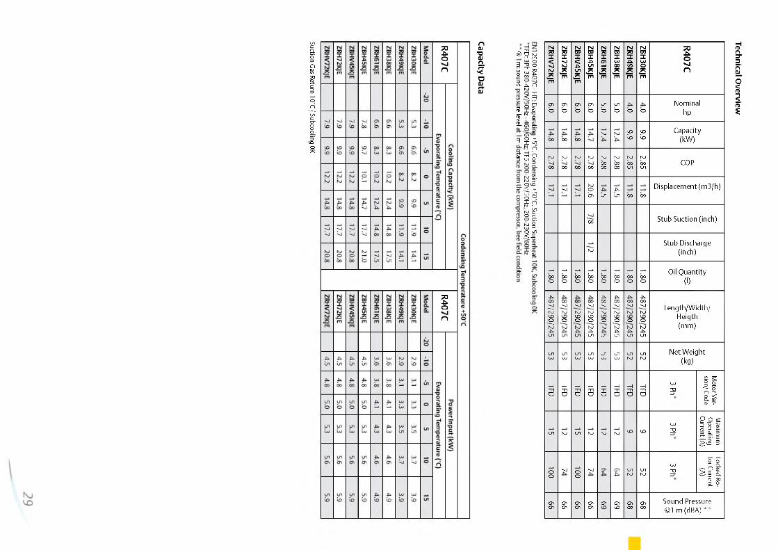
ZRHV72KJE
ZRH72KJE
ZBHV45KJE
ZBH45KJE
ZRH61KJE
ZBH38KJE
ZRH49KJE
ZBH30KJE
R407CCDO
CDO
CDO
CD0
unO
un0 O O
Nominalhp
00 00 00NJ NJ <p
IdJDId
Capacity(kW)
NJ00
NJ00
NJ00
NJ00
NJ0000
NJ0000
NJ00un
NJ00un COP
--J NJOCT) un
4̂un 00 00
Displacement (m3/h)
"oo Stub Suction (inch)
NJStub Discharge
(inch)
000
000
000
000
00O 00O 00O 000
Oil Quantity (1)
487/290/245
00--JNJONJun
00--JNJIDONJun
00--JNJ<D>ONJ4̂un
4̂00--JNJONJun
4̂00--JNJONJ4̂un
4̂00--JNJONJ4̂un
4̂00--JNJONJ4̂un
Length/Width/Heigth(mm)
unUJ unOJ unOJ unOJ unOJ unOJ unNJ unNJNet Weight
(kg)
—1t iO—I -nO
—It iO—I -nO
—ITlO—It i0
—1 t i O
—1Tl0
OJ“Uzr
Motor Ver
sion/ Code
un NJ un NJ NJ NJ VD VDOJ~ozr
Maxim
um
Operating Current (A)
OO--J OO
--J CT) CT)4̂ unNJ unNJOJ~ozr
Locked Ro
tor Current(A)
cr>CD CT)CT) CT)CT) CT)CT) CT) CT)UD CT)00
CT)00
Sound Pressure @1 m (d BA) **
Technical Overview

http://holodko.ru/

http://holodko.ru/
Refrigeration Applications
Emerson Climate Technologies offers a wide range of solutions
for commercial refrigeration applications. With its long-lasting
expertise in semi- hermetic reciprocating compressor technology
as well as in scroll technology, we can meet the requirements for
most applications - at the small end just like at the large end of
commercial refrigeration.
Completed by the various offerings in the segment of
condensing units, Emerson Climate Technologies is able to offer
the best solution and performance, whether you are looking
for applications in foodservice or processing, supermarkets,
hypermarkets, petrol stations or refrigerated warehousing.
Emerson Climate Technologies' prime focus for its semi-hermetic
reciprocating technology is at the large end of commercial
refrigeration. Here aspects such as reliability, serviceability and
capacity modulation are of importance and they are perfectly
provided by Emerson Climate Technologies' semi-hermetic
reciprocating compressors. Innovations like the Discus™ and
Stream technologies, digital modulation and CoreSense™
Diagnostics for advanced protection and preventive maintenance
keep semi-hermetic at the forefront of compressor technology.
Especially when compact equipment, energy efficiency and
reliability are musts, the scroll technology is the preferred choice
for refrigeration applications. With developments such as vapor
injection and digital modulation, scroll has become the leading
technology and is widely recognized in the refrigeration market.
What ever the chosen technology and product solution, Emerson
Climate Technologies' range meets the specific refrigeration
needs covering the entire spectrum of medium and low
temperature applications whether using standard HFCs, low
GWP or natural refrigerants.
31
http://holodko.ru/
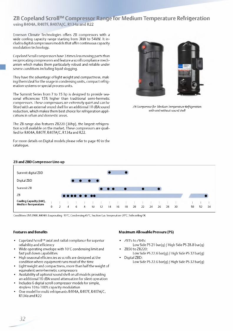
ge for MZB Copeland Scroll™ Compressor Range for Medium Temperature Refrigerationusing R404A, R407F, R407A/C, R134a and R22
Emerson Climate Technologies offers ZB compressors with a wide cooling capacity range starting from 3kW to 54kW. It includes digital compressors models that offer continuous capacity modulation technology.
Copeland Scroll compressors have 3 times less moving parts than reciprocating compressors and feature a scroll compliance mechanism which makes them particularly robust and reliable under severe conditions including liquid slugging.
They have the advantage of light weight and compactness, making them ideal for the usage in condensing units, compact refrigeration systems or special process units.
The Summit Series from 7 to 15 hp is designed to provide seasonal efficiencies 15% higher than traditional semi-hermetic compressors. These compressors are extremely quiet and can be fitted with an external sound shell for an additional 10 dBA sound reduction, which makes them best choice for refrigeration applications in urban and domestic areas.
ZB Compressor for Medium Temperature Refrigeration with and without sound shell
The ZB range also features ZB220 (30hp), the largest refrigeration scroll available on the market. These compressors are qualified for R404A, R407F, R407A/C, R134a and R22.
For more details on Digital models please refer to page 40 in the catalogue.
ZB and ZBD Compressor Line-up
Summit digital ZBD
Digital ZBD
Summit ZB
ZB
Cooling Capacity (kW), Medium Temperature
r a
10 12 14 16 18 20 22 24 26 28 30 50 52 540 2 4 6 8
Conditions EN12900, R404A: Evaporating -10°C, Condensing 45°C, Suction Gas Temperature 20°C, Subcooling 0K
Features and Benefits
• Copeland Scroll™ axial and radial compliance for superior reliability and efficiency
• Wide operating envelope with 10°C condensing limit and fast pull down capabilities
• High seasonal efficiencies as scrolls are designed at the condition where equipment runs most of the time
• Light weight and compactness, more than half the weight of equivalent semi-hermetic compressors
• Availability of optional sound shell on all models providing an additional 10 dBA sound attenuation for silent operation
• Includes 6 digital scroll compressor models for simple, stepless 10 to 100% capacity modulation
• One model for multi refrigerants R404A, R407F, R407A/C, R134a and R22
Maximum Allowable Pressure (PS)
• ZB15 to ZB45:Low Side PS 21 bar(g) / High Side PS 28.8 bar(g)
• ZB50 to ZB220:Low Side PS 22.6 bar(g) / High Side PS 32 bar(g)
• Digital ZBD:Low Side PS 22.6 bar(g) / High Side PS 32 bar(g)
32

http://holodko.ru/
Operating Envelope R404A Operating Envelope R134a
Evaporating Temperature °C Evaporating Temperature °C-------- 20°C Suction Gas ReUim -------- 10K Superheat -------- 20°C Suction Gas Return -------- 10K Superheat
Refer to Emerson’s Select 7.7 selection software for individual model operating envelopes and other refrigerants.
Technical Overview
R404A
Nom
inal
hp
Capa
city
(kW
) POC
Disp
lacem
ent
(m3/
h)
Rotal
ock
Suct
ion
(inch
)
Rotal
ock
Disc
harg
e (in
ch)
Oil Q
uant
ity
(l)
Leng
th/W
idth
/Hei
gth
(mm
)
Net
Wei
ght
(kg)
Motor Version/ Code
Maximum Operating Current (A)
Locked Rotor Current (A)
Soun
d Pr
essu
re@1
m
(dBA
) **
*
1 Ph* 3 Ph** 1 Ph* 3 Ph** 1 Ph* 3 Ph**
ZB15KCE 2.0 3.3 1 .8 5.9 3/4 1 / 2 1.30 241/241/382 25 PFJ TFD 13 5 58 26 55
ZB19KCE 2.5 4.2 2.0 6.8 1 1/4 1 1.50 242/242/369 27 PFJ TFD 13 7 61 32 55
ZB21KCE 3.0 5.1 2.0 8.6 1 1/4 1 1.24 243/244/392 29 PFJ TFD 16 7 82 40 58
ZB26KCE 3.5 5.8 2.0 10 .0 1 1/4 1 1.45 243/244/406 28 PFJ TFD 18 9 97 46 58
ZB29KCE 4.0 6.8 2.1 11.4 1 1/4 1 1.50 242/242/423 29 TFD 10 50 59
ZB30KCE 4.0 6.9 2.0 11.7 1 1/4 1 1.90 242/242/438 35 PFJ TFD 26 10 142 49 59
ZB38KCE 5.0 8.5 2.0 14.4 1 1/4 1 1.90 242/242/438 37 PFJ TFD 32 13 142 66 61
ZB42KCE 5.5 9.7 2.1 16.2 1 1/4 1 1.90 251/246/450 40 PFJ 36 150 62
ZB45KCE 6.0 10 .1 2.1 17.1 1 1/4 1 1.90 242/242/458 40 TFD 13 74 61
ZB48KCE 7.0 1 1 . 6 2.1 18.8 1 1/4 1 1/4 1.80 241/247/456 39 TFD 14 10 1 62
ZB50KCE 7.0 11.9 2.1 19.8 1 1 / 8 7/8 2.65 264/284/480 57 TFD 15 10 0 64
ZB58KCE 8.0 13.3 2.1 22 .1 1 3/4 1 1 /4 2.65 264/284/478 57 TFD 15 95 65
ZB6 6KCE 9.0 15.1 2.1 24.9 1 3/4 1 1 /4 3.38 264/284/533 60 TFD 18 1 1 1 66
ZB76KCE 10 .0 17.9 2.2 29.1 1 3/4 1 1 /4 3.38 264/284/546 61 TFD 20 118 66
ZB95KCE 13.0 21.7 2.1 36.4 1 3/4 1 1 /4 3.38 264/285/552 65 TFD 28 140 67
ZB114KCE 15.0 25.8 2.0 43.4 1 3/4 1 1 /4 3.38 264/285/552 66 TFD 33 174 71
ZB220KCE 30.0 53.2 2 .2 87.5 x N
™ 5, 3
13/4 x 12UN
6.30 448/392/717 176 TWM 69 310 78
Conditions EN12900 : MT, Evaporating -10°C, Condensing 45°C, Suction Gas Temperature 20°C, Subcooling 0K* 1 Ph: 230V/ 50Hz ** 3 Ph: 380-420V/ 50Hz*** @ 1 m: sound pressure level at 1 m distance from the compressor, free field condition
33

http://holodko.ru/
Capacity Data
Condensing Tem perature +40°C
R404ACooling Capacity (kW )
R404APow er Input (kW )
Evaporating Tem perature °C) Evaporating Tem perature °C)
Model -35 -30 -25 - 2 0 -15 - 1 0 -5 Model -35 -30 -25 - 2 0 -15 - 1 0 -5
ZB15KCE 1.4 1.9 2.4 3.0 3.7 4.5 ZB15KCE 1.7 1.7 1.7 1 . 6 1 . 6 1.5
ZB19KCE 2 . 0 2.5 3.1 3.8 4.5 5.4 ZB19KCE 1.9 1.9 1.9 1.9 1.9 1.9
ZB21KCE 2.4 3.0 3.7 4.5 5.5 6 .6 ZB21KCE 2 . 2 2 . 2 2 . 2 2 . 2 2 . 2 2 . 2
ZB26KCE 2 . 8 3.5 4.3 5.3 6.4 7.6 ZB26KCE 2 . 6 2 . 6 2 . 6 2 . 6 2 . 6 2 . 6
ZB29KCE 3.2 4.1 5.0 6 .2 7.5 9.0 ZB29KCE 2 . 8 2.9 2.9 2.9 2.9 2 . 8
ZB30KCE 3.2 4.1 5.0 6 .2 7.5 9.0 ZB30KCE 3.0 3.0 3.0 3.0 3.0 3.0
ZB38KCE 4.1 5.1 6.3 7.7 9.3 1 1 . 2 ZB38KCE 3.7 3.8 3.8 3.8 3.8 3.8
ZB42KCE** 4.6 5.7 7.1 8.7 1 0 . 6 12.7 ZB42KCE** 4.2 4.2 4.2 4.2 4.2 4.2
ZB45KCE 4.8 6 .0 7.4 9.1 1 1 . 0 13.2 ZB45KCE 4.3 4.3 4.3 4.3 4.3 4.3
ZB48KCE 5.5 6.9 8 .6 10.5 12.7 15.2 ZB48KCE 4.9 4.9 4.9 4.9 4.9 4.9
ZB50KCE 2 .8 * 5.9 8 . 2 1 0 . 6 13.1 15.8 ZB50KCE 5.2* 5.2 5.1 5.1 5.1 5.1
ZB58KCE 4.2* 7.2 9.4 11.9 14.5 17.5 ZB58KCE 5.6* 5.6 5.6 5.6 5.7 5.7
ZB6 6 KCE 6 .0 * 8.9 1 1 . 1 13.6 16.4 19.7 ZB6 6 KCE 6 . 1 * 6 . 2 6.3 6.3 6.4 6.4
ZB76KCE 7.0* 10.4 13.0 16.0 19.4 23.3 ZB76KCE 7.0* 7.1 7.2 7.3 7.3 7.4
ZB95KCE 7.6* 10.7* 15.6 19.5 23.8 28.7 ZB95KCE 9.6* 9.4* 9.4 9.3 9.4 9.5
ZB114KCE 8.5* 12.3* 18.3 23.0 28.3 34.4 ZB114KCE 1 1 .6 * 11.4* 11.3 11.3 11.3 11.4
ZB220KCE 28.4* 39.2 47.7 57.5 68.9 ZB220KCE 21.4* 2 1 . 8 2 2 . 0 2 2 . 2 22.4
Suction Gas Return 20°C / Subcooling 0K * Suction Superheat 10K / Subcooling 0K ** Single Phase only Preliminary data
Condensing Tem perature +40°C
R407ACooling Capacity (kW )
R407APow er Input (kW )
Evaporating Tem perature °C) Evaporating Tem perature °C)
Model -35 -30 -25 - 2 0 -15 - 1 0 -5 Model -35 -30 -25 - 2 0 -15 - 1 0 -5
ZB15KCE 1 .6 * 2 . 1 * 2 . 8 3.5 4.2 ZB15KCE 1.5* 1.5* 1.5 1.5 1.5
ZB19KCE 2 . 1 * 2 .6 * 3.4 4.2 5.2 ZB19KCE 1.7* 1.7* 1 . 8 1 . 8 1 . 8
ZB21KCE 2.5* 3.2* 4.1 5.1 6 . 2 ZB21KCE 2 .0 * 2 . 1 * 2 . 1 2 . 1 2 . 1
ZB26KCE 2 .6 * 3.6* 4.7 5.8 7.1 ZB26KCE 2.3* 2.3* 2.3 2.3 2.4
ZB30KCE 3.4* 4.4* 5.8 7.3 8.9 ZB30KCE 2.7* 2.7* 2.7 2.7 2 . 8
ZB38KCE 4.2* 5.4* 7.2 8.9 1 1 ZB38KCE 3.2* 3.2* 3.3 3.3 3.4
ZB45KCE 4.9* 6.3* 8 . 2 1 0 . 2 12.4 ZB45KCE 3.8* 3.9* 4.0 4.0 4.0
Suction Gas Return 20°C / Subcooling 0K * Suction Superheat 10K / Subcooling 0K
Condensing Tem perature +40°C
R407CCooling Capacity (kW )
R407CPow er Input (kW )
Evaporating Tem perature [°C) Evaporating Tem perature [°C)
Model -35 -30 -25 - 2 0 -15 - 1 0 -5 Model -35 -30 -25 - 2 0 -15 - 1 0 -5
ZB15KCE 1 .6 * 1.9* 2.3* 2.9 3.6 ZB15KCE 1 .2 * 1.3* 1.3* 1.3 1.3
ZB19KCE 1 .6 * 2 . 1 * 2.7* 3.5 4.4 ZB19KCE 1 .6 * 1 .6 * 1 .6 * 1 . 6 1 . 6
ZB21KCE 2 . 1 * 2.9* 3.7* 4.7 5.8 ZB21KCE 1.9* 2 .0 * 2 .0 * 2 . 0 2 . 0
ZB26KCE 2 .2 * 2.9* 3.7* 4.9 6 . 2 ZB26KCE 2 .2 * 2 .2 * 2 .2 * 2 . 2 2 . 2
ZB30KCE 2.7* 3.6* 4 .8* 6 . 2 7.7 ZB30KCE 2.5* 2.5* 2 .6 * 2 . 6 2 . 6
ZB38KCE 3.1* 4.2* 5.6* 7.4 9.4 ZB38KCE 2.9* 3.0* 3.1* 3.1 3.2
ZB42KCE** 4.4* 5.7* 7.2* 9.1 1 1 . 2 ZB42KCE** 3.8* 3.8* 3.8* 3.8 3.6
ZB45KCE 3.7* 5.3* 7.1* 9.2 11.5 ZB45KCE 3.4* 3.6* 3.6* 3.7 3.7
Suction Gas Return 20°C / Subcooling 0K *Suction Superheat 10K / Subcooling 0K * * Single Phase only
34

http://holodko.ru/
Capacity Data
Condensing Tem perature +40°C
R134aCooling Capacity (kW )
R134aPow er Input (kW )
Evaporating Tem perature (°C) Evaporating Tem perature (°C)
Model -35 -30 -25 - 2 0 -15 - 1 0 -5 Model -35 -30 -25 - 2 0 -15 - 1 0 -5
ZB15KCE 1.4 1.7 2 . 2 2.7 ZB15KCE 0.9 0.9 0.9 0.9
ZB19KCE 1 . 6 2 . 0 2.5 3.2 ZB19KCE 1 . 1 1 . 1 1 . 1 1 . 1
ZB21KCE 2 . 0 2.5 3.2 4.0 ZB21KCE 1.3 1.3 1.3 1.3
ZB26KCE 2.3 2.9 3.7 4.6 ZB26KCE 1.5 1.5 1.5 1.5
ZB30KCE 2.5* 3.4 4.3 5.4 ZB30KCE 1.7* 1.7 1.7 1 . 8
ZB38KCE 3.0* 4.2 5.4 6.7 ZB38KCE 2 . 1 * 2 . 1 2 . 1 2 . 2
ZB42KCE** 3.8 4.8 6.0 7.5 ZB42KCE** 2.5 2.5 2.5 2.4
ZB45KCE 3.8* 5.1 6.4 8 .0 ZB45KCE 2.4* 2.4 2.5 2.5
ZB50KCE 4.6 5.9 7.4 9.1 ZB50KCE 3.0 3.0 3.0 3.1
ZB58KCE 5.2 6 .6 8.3 10.3 ZB58KCE 3.4 3.4 3.4 3.4
ZB6 6 KCE 6 .0 7.6 9.5 1 1 . 8 ZB6 6 KCE 3.8 3.7 3.8 3.8
ZB76KCE 6.9 8 .6 1 0 . 8 13.5 ZB76KCE 4.4 4.4 4.4 4.5
ZB95KCE 8 . 2 1 0 . 8 13.8 17.1 ZB95KCE 5.4 5.5 5.6 5.6
ZB114KCE 9.6 12.7 16.3 20.4 ZB114KCE 6 .6 6 .6 6.7 6.7Suction Gas Return 20°C / Subcooling 0K * Suction Superheat 10K / Subcooling 0K ** Single Phase only
Condensation Tem perature +40°C
R407F Cooling Capacity (kW ) R407F Pow er Input (kW )
Evaporating Tem perature (°C) Evaporating Tem perature (°C)
Model -35 -30 -25 - 2 0 -15 - 1 0 -5 Model -35 -30 -25 - 2 0 -15 - 1 0 -5
ZB15KCE* 3.3 4.1 ZB15KCE* 1 . 6 1.5
ZB19KCE* 4.1 5.0 ZB19KCE* 1.9 1 . 8
ZB21KCE* 4.9 6. 0 ZB21KCE* 2 . 2 2 . 2
ZB26KCE* 5.7 7.0 ZB26KCE* 2 . 6 2 . 6
ZB30KCE 4.2* 5.5* 7.2 8.9 ZB30KCE 2.9* 2.9* 2.9 2.9
ZB38KCE 5.2* 6.9* 8.9 1 1 . 0 ZB38KCE 3.7* 3.7* 3.7 3.7
ZB45KCE 6 .0 * 8 . 1 * 10.5 13.0 ZB45KCE 4.1* 4 .2* 4.3 4.2
Suction Gas Return 20°C / Subcooling 0K Preliminary data* Suction Superheat 10K / Subcooling 0K
Condensation Tem perature +40°C
R22Cooling Capacity (kW )
R22Pow er Input (kW )
Evaporating Tem perature (°C) Evaporating Tem perature (°C)
Model -35 -30 -25 - 2 0 -15 - 1 0 -5 Model -35 -30 -25 - 2 0 -15 - 1 0 -5
ZB15KCE 1.4* 2 . 1 * 2 .8 * 3.5 4.2 ZB15KCE 1.5* 1.4* 1.4* 1.4 1.4
ZB19KCE 1.9* 2.5* 3.2* 4.0 4.8 ZB19KCE 1 .6 * 1 .6 * 1 .6 * 1 . 6 1 . 6
ZB21KCE 2 .0 * 3.0* 4 .0* 5.1 6 . 2 ZB21KCE 2 .2 * 2 . 1 * 2 .0 * 2 . 0 2 . 0
ZB26KCE 2.7* 3.5* 4 .4* 5.6 6 .8 ZB26KCE 2 .2 * 2 .2 * 2 .2 * 2 . 2 2 . 2
ZB30KCE 2 .2 * 3.2* 4 .5* 6 .0 7.7 ZB30KCE 2 .6 * 2.7* 2.7* 2.7 2.7
ZB38KCE 3.8* 4.9* 6.3* 8 .0 1 0 . 0 ZB38KCE 2.9* 3.0* 3.1* 3.1 3.2
ZB42KCE** 5.2* 6 .6 * 8 . 1 * 9.9 11.9 ZB42KCE** 3.9* 3.8* 3.8* 3.7 3.6
ZB45KCE 4.5* 6.4* 8.3* 10.3 12.5 ZB45KCE 3.4* 3.6* 3.7* 3.7 3.8
ZB50KCE 4.6* 6.9* 9.2* 11.7 14.4 ZB50KCE 4.4* 4 .4* 4.4* 4.3 4.3
ZB58KCE 5.1* 7.5* 1 0 . 1 * 13.0 16.1 ZB58KCE 4.8* 4.9* 4.9* 4.9 4.9
ZB6 6 KCE 7.4* 9.6* 1 2 .2 * 15.1 18.4 ZB6 6 KCE 5.1* 5.2* 5.3* 5.4 5.4
ZB76KCE 8.9* 11.5* 14.4* 17.8 21.7 ZB76KCE 5.9* 6 . 1 * 6 .2 * 6.3 6.4
ZB95KCE 16.8* 21.4* 26.5* ZB95KCE 8 .0 * 8 . 1 * 8 .2 *
ZB114KCE 19.9* 25.5* 31.7* ZB114KCE 9.6* 9.6* 9.7*Suction Gas Return 20°C / Subcooling 0K * Suction Superheat 10K / Subcooling 0K * * Single Phase only
35
http://holodko.ru/
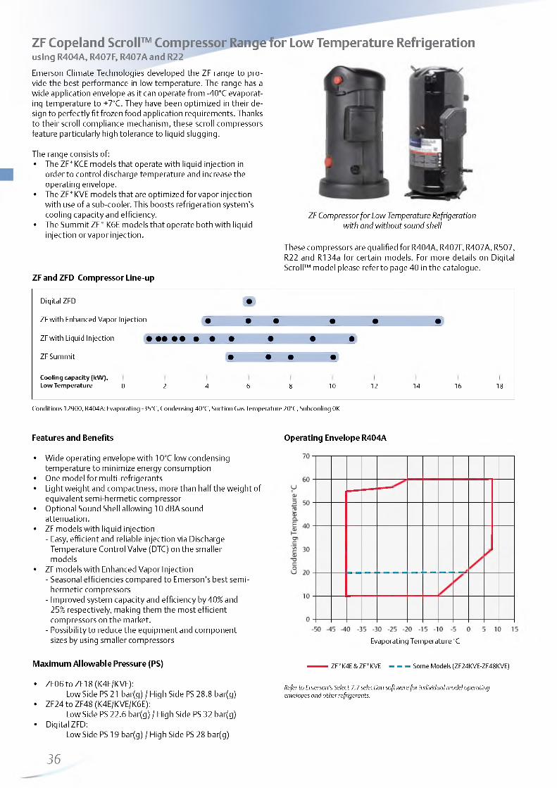
ZF Copeland Scroll™ Compressor Range for Low Temperature Refrigerationusing R404A, R407F, R407A and R22
Emerson Climate Technologies developed the ZF range to provide the best performance in low temperature. The range has a wide application envelope as it can operate from -40°C evaporating temperature to +7°C. They have been optimized in their design to perfectly fit frozen food application requirements. Thanks to their scroll compliance mechanism, these scroll compressors feature particularly high tolerance to liquid slugging.
The range consists of:• The ZF*KCE models that operate with liquid injection in
order to control discharge temperature and increase the operating envelope.
• The ZF*KVE models that are optimized for vapor injection with use of a sub-cooler. This boosts refrigeration system's cooling capacity and efficiency.
• The Summit ZF* K6E models that operate both with liquid injection or vapor injection.
ZF and ZFD Compressor Line-up
ZF Compressor for Low Temperature Refrigeration with and without sound shell
These compressors are qualified for R404A, R407F, R407A, R507, R22 and R134a for certain models. For more details on Digital Scroll™ model please refer to page 40 in the catalogue.
Digital ZFD W
ZF with Enhanced Vapor Injection 9 • • • • •
ZF with Liquid Injection • • • • • • • • • • •
ZF Summit • • • •
Cooling capacity (kW),Low Temperature 0 2 4 6 8 1 0 1 2 14 16 18
Conditions 12900, R404A: Evaporating -35°C, Condensing 40°C, Suction Gas Temperature 20°C, Subcooling 0K
Features and Benefits
• Wide operating envelope with 10°C low condensing temperature to minimize energy consumption
• One model for multi-refrigerants• Light weight and compactness, more than half the weight of
equivalent semi-hermetic compressor• Optional Sound Shell allowing 10 dBA sound
attenuation.• ZF models with liquid injection
- Easy, efficient and reliable injection via Discharge Temperature Control Valve (DTC) on the smaller models
• ZF models with Enhanced Vapor Injection- Seasonal efficiencies compared to Emerson's best semi-
hermetic compressors- Improved system capacity and efficiency by 40% and
25% respectively, making them the most efficient compressors on the market.
- Possibility to reduce the equipment and component sizes by using smaller compressors
Maximum Allowable Pressure (PS)
• ZF06 to ZF18 (K4E/KVE):Low Side PS 21 bar(g) / High Side PS 28.8 bar(g)
• ZF24 to ZF48 (K4E/KVE/K6E):Low Side PS 22.6 bar(g) / High Side PS 32 bar(g)
• Digital ZFD:Low Side PS 19 bar(g) / High Side PS 28 bar(g)
36
Operating Envelope R404A
Evaporating Temperature °C
— ZF*K4E & ZF*KVE - - - Some Models (ZF24KVE-ZF48KVE)
Refer to Emerson’s Select 7.7 selection software for individual model operating envelopes and other refrigerants.

http://holodko.ru/
Technical Overview
R404AN
omin
alhp
Capa
city
(kW
)
COP
Disp
lace
men
t (m
3/h)
Rota
lock
Su
ctio
n (in
ch)
Rota
lock
D
isch
arge
(in
ch)
Oil
Qua
ntity
(l)
Leng
th/W
idth
/Hei
gth
(mm
)
Net
Wei
ght
(kg)
Motor Version/ Code
Maximum Operating Current (A)
Locked Rotor Current
(A)
Soun
d Pr
essu
re
@1
m (d
BA)
***
3 Ph** 3 Ph** 3 Ph**
Models w ith Liquid In jection
ZF06K4E 2 . 0 1.4 1 . 0 5.9
1 3/41
1.30 242/242/369 25 TFD 5 52 57
ZF08K4E 2.5 1 . 8 1 . 1 7.3 1.48 243/244/392 27 TFD 6 32 59
ZF09K4E 3.0 1.9 1 . 1 8 .0 1.50 243/244/392 27 TFD 6 40 62
ZF11K4E 3.5 2.5 1 . 1 9.9 1.50 243/244/406 28 TFD 7 46 63
ZF13K4E 4.0 2 . 8 1 . 2 1 1 . 8 1.40 241/244/490 38 TFD 8 52 65
ZF15K4E 5.0 3.4 1 . 2 14.5 1.70 241/244/490 39 TFD 1 0 64 65
ZF18K4E 6 .0 4.2 1 . 2 17.1 1.70 241/244/490 41 TFD 13 74 67
ZF24K4E 7.5 5.2 1 . 1 20.9 1 1/4 4.14 368/316/542 1 0 0 TWD 16 99 72
ZF33K4E 10.5 7.1 1 . 2 28.81 3/4 1 1 /4
4.14 368/319/525 93 TWD 2 2 127 72
ZF40K4E 12.5 8 .8 1 . 2 35.6 4.14 368/324/532 103 TWD 25 167 72
ZF48K4E 15.0 1 0 . 6 1 . 1 42.8 2 1/4 1 1/4 4.14 324/294/579 1 1 2 TWD 29 198 72
Models w ith Enhanced Vapor Injection
ZF13KVE 4.0 4.0 1.3 11.7
1 3/4
11.90 241/244/442 38 TFD 9 64 63
ZF18KVE 6 .0 6 .0 1.5 17.1 1.90 308/246/438 39 TFD 13 74 67
ZF24KVE 7.5 7.3 1.4 20.9
1 1 /4
4.14 316/368/542 1 0 0 TWD 16 99 70
ZF33KVE 10.5 9.9 1.4 28.8 4.14 368/319/525 93 TWD 2 1 127 72
ZF40KVE 12.5 1 2 . 0 1.5 35.6 4.14 316/368/550 96 TWD 27 167 72
ZF48KVE 15.0 15.0 1.5 42.8 2 1/4 1 3/4 4.14 324/294/579 1 1 2 TWD 31 198 72
Conditions EN12900 : LT, Evaporating -35°C, Condensing 40°C, Suction Gas Temperature 20°C, Subcooling 0K** 3 Ph: 380-420V/ 50Hz*** @ 1 m: sound pressure level at 1 m distance from the compressor, free field condition
Technical Overview - “Summit” Compressors
R404A
Nom
inal
hp
Capa
city
(kW
)
COP
Dis
plac
emen
t(m
3/h)
Rota
lock
Su
ctio
n (in
ch)
Rota
lock
D
isch
arge
(in
ch)
Oil
Qua
ntity
(l)
Length/Width/Heigth(mm)
thie g) W g(k t ( e N
Motor Ver- sion/ Code
Maximum Operating Current (A)
Locked Rotor Current
(A)So
und
Pres
sure
@1
m
(dBA
) **
*
3 Ph** 3 Ph** 3 Ph**
ZF25K6E 7.5 5.1 1 . 2 21.3 1 1/4 1 1.90 308/246/438 41 TFD 14 90 6 8
ZF34K6E 9.0 6 .8 1.3 29.1 1 3/4 1 1/4 3.20 280/279/456 63 TFD 19 1 0 0 6 8
ZF41K6E 1 0 . 0 8 .0 1.3 35.3 1 3/4 1 1/4 3.20 280/279/546 63 TFD 2 1 118 69
ZF49K6E 13.0 1 0 . 1 1 . 2 42.3 1 3/4 1 1/4 3.20 280/279/564 63 TFD 31 118 71
Conditions EN12900 : LT, Evaporating -35°C, Condensing 40°C, Suction Gas Temperature 20°C, Subcooling 0K** 3 Ph: 380-420V/ 50Hz*** @ 1 m: sound pressure level at 1 m distance from the compressor, free field condition Preliminary data
37

http://holodko.ru/
Capacity Data
Condensing Tem perature +40°C
M odels w ith Liquid Injection
R404ACooling Capacity (kW )
R404APow er Input (kW )
Evaporation Tem perature <°C) Evaporation Tem perature <°C)
Model -35 -30 -25 - 2 0 -15 - 1 0 -5 Model -35 -30 -25 - 2 0 -15 - 1 0 -5
ZF06K4E 1.4 1 . 8 2 . 2 2 . 6 3.1 3.8 4.5 ZF06K4E 1.4 1.4 1.5 1.5 1 . 6 1.7 1 . 8
ZF08K4E 1 . 8 2 . 2 2 . 8 3.4 4.1 4.8 5.7 ZF08K4E 1 . 6 1.7 1 . 8 1.9 2 . 0 2 . 1 2 . 2
ZF09K4E 1.9 2.4 3.0 3.6 4.4 5.2 6.3 ZF09K4E 1 . 8 1 . 8 1.9 1.9 2 . 0 2 . 1 2 . 2
ZF11K4E 2.5 3.0 3.7 4.5 5.4 6.5 7.8 ZF11K4E 2 . 2 2 . 2 2.3 2.4 2.5 2 . 6 2.7
ZF13K4E 2 . 8 3.5 4.3 5.3 6.4 7.7 9.1 ZF13K4E 2.3 2.4 2.5 2 . 6 2.7 2 . 8 3.0
ZF15K4E 3.4 4.3 5.3 6.4 7.8 9.4 1 1 . 2 ZF15K4E 2 . 8 3.0 3.1 3.2 3.4 3.6 3.8
ZF18K4E 4.2 5.2 6.4 7.8 9.4 11.3 13.5 ZF18K4E 3.4 3.6 3.7 3.8 4.0 4.2 4.4
ZF24K4E 5.2 6.4 7.9 9.6 1 1 . 6 13.8 16.4 ZF24K4E 4.5 4.7 5.0 5.2 5.4 5.6 5.8
ZF33K4E 7.1 8.9 10.9 13.3 16.1 19.3 23.0 ZF33K4E 5.8 6 . 2 6.5 6.9 7.2 7.5 7.8
ZF40K4E 8.8 1 1 . 0 13.5 16.4 19.8 23.7 28.2 ZF40K4E 7.4 7.8 8 . 2 8 .6 9.0 9.4 9.8
ZF48K4E 1 0 . 6 13.2 16.3 2 0 . 0 24.1 28.9 34.4 ZF48K4E 9.7 1 0 . 2 1 0 . 6 1 1 . 1 1 1 . 6 1 2 . 1 12.7
Models w ith Enhanced Vapor In jection
-35 -30 -25 - 2 0 -15 - 1 0 -5 -35 -30 -25 - 2 0 -15 - 1 0 -5
ZF13KVE 4.0 4.9 6.0 7.2 8.6 1 0 . 1 11.7 ZF13KVE 3.0 3.0 3.1 3.2 3.3 3.4 3.5
ZF18KVE 6. 0 7.1 8.5 1 0 . 1 11.9 14.0 16.4 ZF18KVE 4.0 4.2 4.4 4.6 4.7 4.9 5.0
ZF24KVE 7.3 8.9 10.7 12.7 15.0 17.5 20.4 ZF24KVE 5.2 5.4 5.6 5.8 6 .0 6.3 6.5
ZF33KVE 9.9 1 2 . 0 14.5 17.3 20.4 24.1 28.1 ZF33KVE 6.9 7.2 7.5 7.7 8 .0 8.3 8.6
ZF40KVE 1 2 . 0 15.3 18.8 22.5 26.5 30.9 35.7 ZF40KVE 8 .0 8 .8 9.5 9.9 10.3 1 0 . 6 10.9
ZF48KVE 15.0 18.2 2 1 . 8 25.7 30.0 34.7 39.9 ZF48KVE 9.8 10.4 1 1 . 0 1 1 . 6 1 2 . 2 12.9 13.5
ZF Sum m it M odels - w ith Liquid Injection
-35 -30 -25 - 2 0 -15 - 1 0 -5 -35 -30 -25 - 2 0 -15 - 1 0 -5
ZF25K6E 5.1 6.3 7.8 9.6 11.7 14.1 16.8 ZF25K6E 4.1 4.4 4.7 4.9 5.1 5.3 5.5
ZF34K6E 6 .8 8.5 10.4 1 2 . 6 15.3 18.3 2 1 . 8 ZF34K6E 5.2 5.5 5.8 6 .0 6.3 6 .6 6.9
ZF41K6E 8 .0 1 0 . 0 12.3 14.9 18.0 21.5 25.7 ZF41K6E 6.4 6.7 7.1 7.4 7.8 8 .1 8.5
ZF49K6E 10.7 13.3 16.4 2 0 . 0 24.1 28.9 34.3 ZF49K6E 9.7 1 0 . 2 1 0 . 6 1 1 . 1 1 1 . 6 1 2 . 1 12.7
ZF Sum m it Models - w ith Enhanced Vapor In jection
-35 -30 -25 - 2 0 -15 - 1 0 -5 -35 -30 -25 - 2 0 -15 - 1 0 -5
ZF25K6E 7.8 9.5 11.4 13.5 15.9 18.5 21.4 ZF25K6E 5.0 5.3 5.5 5.7 5.9 6 .1 6 . 2
ZF34K6E 1 0 . 2 12.4 14.9 17.6 20.7 24.1 27.8 ZF34K6E 6.3 6.6 6.9 7.2 7.5 7.8 8 .1
ZF41K6E 1 2 . 6 15.3 18.3 21.7 25.5 29.6 34.2 ZF41K6E 7.8 8 .2 8 .6 9.0 9.4 9.8 1 0 . 2
ZF49K6E 15.1 18.3 21.9 26.0 30.5 35.5 41.0 ZF49K6E 9.6 1 0 . 1 1 0 . 6 1 1 . 1 11.5 1 2 . 0 12.5
Suction Gas Return 20°C / Subcooling 0K Preliminary data
Condensing Tem perature +40°C
R134aCooling Capacity (kW )
R134aPow er Input (kW )
Evaporating Tem perature °C) Evaporating Tem perature <°C)
Model -35 -30 -25 - 2 0 -15 - 1 0 -5 Model -35 -30 -25 - 2 0 -15 - 1 0 -5
ZF13K4E 1.5 2 . 0 2.5 3.1 3.8 4.6 5.6 ZF13K4E 1.4 1.5 1.5 1 . 6 1.7 1 . 8 1 . 8
ZF15K4E 1 . 8 2.3 2.9 3.7 4.6 5.6 6.9 ZF15K4E 1.7 1 . 8 1.9 2 . 0 2 . 1 2 . 2 2.3
ZF18K4E 2 . 1 2.7 3.4 4.3 5.4 6.7 8 .1 ZF18K4E 2.3 2.3 2.4 2.5 2 . 6 2 . 8 2.9
ZF24K4E 2.7 3.5 4.4 5.4 6.7 8 . 2 1 0 . 0 ZF24K4E 2.9 3.0 3.1 3.2 3.3 3.4 3.5
ZF33K4E 3.6 4.7 6 . 1 7.6 9.5 1 1 . 6 13.9 ZF33K4E 3.6 3.7 3.9 4.1 4.3 4.6 4.8
Suction Gas Return 20°C / Subcooling 0K
38—

http://holodko.ru/
Capacity Data
Condensing Tem perature +40°C
R407ACooling Capacity (kW )
R407APow er Input (kW )
Evaporating Tem perature <°C) Evaporating Tem perature (°C)
Model -35 -30 -25 - 2 0 -15 - 1 0 -5 Model -35 -30 -25 - 2 0 -15 - 1 0 -5
ZF09K4E 1.9 2.3 2.9 3.5 4.3 5.2 6 . 2 ZF09K4E 1.7 1.9 2 . 1 2.3 2 . 6 3.0 3.4
ZF11K4E 2 . 1 2 . 6 3.3 4.1 5.0 6 .1 7.4 ZF11K4E 1.5 1.7 1.9 2 . 0 2 . 2 2.4 2.5
ZF13K4E 2 . 2 2 . 8 3.5 4.4 5.5 6.5 7.7 ZF13K4E 2 . 1 2 . 2 2.3 2.3 2.4 2.5 2.5
ZF15K4E 2.7 3.4 4.3 5.5 6.7 8 .1 9.7 ZF15K4E 2.5 2.7 2 . 8 2.9 3.0 3.1 3.0
ZF18K4E 3.3 4.1 5.2 6 .6 8 .1 9.7 11.5 ZF18K4E 3.0 3.2 3.3 3.5 3.6 3.7 3.5
Models w ith Enhanced Vapor Injection
-35 -30 -25 - 2 0 -15 - 1 0 -5 -35 -30 -25 - 2 0 -15 - 1 0 -5
ZF13KVE 3.1 4.0 4.9 6 .0 7.3 8.7 10.4 ZF13KVE 2.3 2.3 2.4 2.5 2 . 6 2.7 2.7
ZF18KVE 4.9 6 .0 7.3 8 .8 1 0 . 8 13.3 16.5 ZF18KVE 3.4 3.5 3.6 3.7 3.9 4.1 4.4
ZF24KVE 5.8 7.2 8 .8 10.7 1 2 . 8 15.1 17.7 ZF24KVE 4.6 4.9 5.1 5.4 5.9 6.4 7.1
ZF33KVE 7.7 9.8 1 2 . 2 14.7 17.2 19.3 2 1 . 0 ZF33KVE 6. 0 6.3 6.5 6.9 7.3 8 .0 8.9
ZF40KVE 1 0 . 2 12.7 15.5 18.8 22.3 26.1 30.1 ZF40KVE 7.0 7.4 7.8 8.3 8.9 9.6 10.5
ZF Sum m it Models - w ith Liquid In jection
-35 -30 -25 - 2 0 -15 - 1 0 -5 -35 -30 -25 - 2 0 -15 - 1 0 -5
ZF25K6E req. req. req. req. req. req. req. ZF25K6E req. req. req. req. req. req. req.
ZF34K6E 8 . 2 1 0 . 1 1 2 . 2 14.8 ZF34K6E 5.5 5.6 5.7 5.9
ZF41K6E 1 0 . 1 12.4 15.0 18.2 ZF41K6E 6 .8 7.0 7.1 7.4
ZF49K6E 1 2 . 1 14.9 18.1 2 1 . 8 ZF49K6E 8.4 8 .6 8 .8 9.1
Suction Gas Return 20°C / Subcooling 0K Preliminary data
Condensing Tem perature +40°C
R407FCooling Capacity (kW )
R407FPow er Input (kW )
Evaporating Tem perature (°C) Evaporating Tem perature (°C)
M odels -35 -30 -25 - 2 0 -15 - 1 0 -5 Models -35 -30 -25 - 2 0 -15 - 1 0 -5
ZF06K4E-TFD* 1 . 2 1 . 6 2 . 0 2.5 3.1 3.7 4.5 ZF06K4E-TFD* 1.5 1.5 1.5 1.5 1 . 6 1 . 6 1.7
ZF08K4E-TFD* 1.5 2 . 0 2.5 3.2 3.9 4.8 5.7 ZF08K4E-TFD* 1 . 8 1 . 8 1 . 8 1.9 1.9 2 . 0 2 . 1
ZF09K4E-TFD* 1.7 2 . 2 2.7 3.4 4.3 5.2 6.3 ZF09K4E-TFD* 1.9 1.9 1.9 1.9 2 . 0 2 . 0 2 . 1
ZF11K4E-TFD* 2 . 1 2.7 3.4 4.3 5.3 6.5 7.8 ZF11K4E-TFD* 2.3 2.3 2.3 2.4 2.4 2.5 2 . 6
ZF13K4E-TFD* 2.5 3.2 4.0 5.0 6 . 1 7.4 8.9 ZF13K4E-TFD* 2.7 2 . 8 2 . 8 2.9 3.0 3.1 3.2
ZF15K4E-TFD* 3.1 4.0 3.5 6 .0 3.7 8.9 1 0 . 8 ZF15K4E-TFD* 3.2 3.4 4.9 3.6 7.4 3.9 4.1
ZF18K4E-TFD* 3.6 4.7 5.9 7.3 8.9 10.9 13.2 ZF18K4E-TFD* 3.8 3.8 3.9 4.0 4.1 4.3 4.5
Suction Gas Return 20°C / Subcooling 0K Preliminary data
Condensing Tem perature +40°C
R22Cooling Capacity (kW )
R22Pow er Input (kW )
Evaporating Tem perature °C) Evaporating Tem perature <°C)
Model -35 -30 -25 - 2 0 -15 - 1 0 -5 Model -35 -30 -25 - 2 0 -15 - 1 0 -5
ZF09K4E 1 . 8 2.3 2 . 8 3.5 4.2 5.1 6 .1 ZF09K4E 1.9 1.9 2 . 0 2 . 0 2 . 1 2 . 1 2 . 2
ZF11K4E 2.3 2.9 3.5 4.3 5.2 6.3 7.5 ZF11K4E 2 . 1 2 . 1 2 . 2 2.3 2.4 2.5 2.7
ZF13K4E 2.7 3.3 4.1 5.0 6 .1 7.3 8.7 ZF13K4E 2.5 2.5 2 . 6 2.7 2 . 8 2.9 3.0
ZF15K4E 3.2 4.1 5.0 6 .1 7.4 8.9 1 0 . 6 ZF15K4E 3.0 3.1 3.2 3.3 3.4 3.6 3.7
ZF18K4E 3.8 4.8 5.9 7.3 8 .8 10.7 12.7 ZF18K4E 3.8 3.8 3.9 4.0 4.1 4.3 4.5
ZF24K4E 4.8 5.9 7.3 8.9 1 0 . 8 13.1 15.6 ZF24K4E 4.4 4.7 4.9 5.1 5.3 5.4 5.6
ZF33K4E 6 . 2 7.9 9.9 12.3 15.0 18.1 21.4 ZF33K4E 5.7 6 .0 6 . 2 6.5 6 .8 7.2 7.6
ZF40K4E 8.3 1 0 . 2 12.4 15.1 18.4 2 2 . 2 26.7 ZF40K4E 7.2 7.5 7.8 8 .1 8.4 8 .8 9.2
ZF48K4E 9.2 11.5 14.1 17.3 2 1 . 1 25.5 30.6 ZF48K4E 8.9 9.3 9.7 1 0 . 1 1 0 . 6 1 1 . 0 11.5
Suction Gas Return 20°C / Subcooling 0K
39

http://holodko.ru/
ZFD & ZBD Copeland Scroll™ Digital Refrigeration
Range for MMedium and Low Temperature
Copeland Scroll Digital ZBD and ZFD compressors provide stepless continuous capacity modulation in medium and low temperature refrigeration applications.
Based on the unique Copeland Compliant Scroll™ design, the Digital modulation operates on a simple mechanism. Capacity control is achieved by separating the scroll sets axially over a small period of time. It is a simple mechanical solution allowing precise temperature control and system efficiency.
Digital Scroll™ technology is a simple modulation solution that can easily and quickly be implemented into any existing system design as no other components are required.
Digital Scroll technology provides continuous, stepless modulation from 10% to 100% with no operating envelope restriction. As a result, system pressures and temperatures are tightly controlled. These compressors provide optimum performance for condensing units, refrigeration packs, process and agricultural units.
The Digital Scroll range consists of:• ZBD models dedicated to medium temperature applications• ZFD models with vapor injection for low temperature
applications• ZOD model designed for use in R744 (CO2) - see page 44
Copeland Scroll Digital for Low and Medium Temperature Refrigeration with and without sound shell
These compressors are qualified for R404A, R407A, R407F for some models and R22 for ZBD only.
Digital Scroll™ Compressor Line-up
ZFD ! •
Summit ZBD • •
ZBD • • • • 1
Medium/Low Temperature kw/Cooling 0 2 4 6 8 10 12 14 16 18 20 22 24
Digital ZBD R404A Evaporating -10°C, Condensing 45°C, Suction Gas Temperature 20°C, Subcooling 0K Digital ZFD: R404A Evaporating -35°C, Condensing 40°C, Suction Gas Temperature 20°C, Subcooling 0K
Features and Benefits
• Continuous modulation from 10% to 100% ensuring a perfect match of capacity and power to the desired load
• An economical and reliable alternative to variable speed drive
• Precise suction pressure control with associated energy savings
• Food quality is maintained by stable evaporating temperatures in the refrigerated areas
• Longer lasting refrigeration equipment due to fewer compressor cycling
• Quick and easy integration into refrigeration equipment, similar to any other scroll compressor
• Availability of optional sound shell on all models providing an additional 10dBA sound attenuation for silent operation
• Availability of Emerson's series of controllers that operate the Digital Scroll™ compressor
Maximum Allowable Pressure (PS)
• Digital ZBD:Low Side PS 22.6 bar(g) / High Side PS 32 bar(g)
• Digital ZFD:Low Side PS 19 bar(g) / High Side PS 28 bar(g)
40
Operating Envelope R404A
Evaporating Temperature °C
ZBD 20°C Suction Gas Return “ “ “ ZBD 10K SuperheatZFD 20°C Suction Gas Return ™ ™ ™ Summit ZBD
Refer to Emerson’s Select 7.7 selection software for individual model operating envelopes and other refrigerants.
—

http://holodko.ru/
Technical Overview
R404AN
omin
alhp
Capa
city
(kW
)
COP
Disp
lace
men
t (m
3/h)
Rota
lock
Su
ctio
n (in
ch)
CDgrarhcis h) D c
^ .E c (ioal
toO'
Oil Q
uant
ity
(l)
Leng
th/W
idth
/Hei
gth
(mm
)
Net
Wei
ght
(kg)
Motor Version/ Code
Maximum Operating Current (A)
Locked Rotor Current (A)
Soun
d Pr
essu
re@1
m
(dBA
) **
*
h*CL JZP
3
h*CL JZP
3
h*CL JZP
3
ZBD21KCE 3.0 5.1 2 . 2 8 1.24 243/243/432 30 PFJ TFD 17 7 97 40 62
ZBD30KCE 4.0 7.0 2 . 2 1 2 1 1.89 241/246/482 37 TFD 8 52 59
ZBD38KCE 5.0 8 .6 2 . 2 14 1/41
1.89 241/246/481 38 TFD 1 1 66 67
ZBD45KCE 6 .0 1 0 . 2 2 . 1 17 1.89 241/246/494 40 TFD 1 2 74 61
ZBD58KCE 8 .0 13.5 2 . 1 2 2 1 1 2.51 264/284/476 60 TFD 15 95 65
ZBD76KCE 1 0 . 0 17.9 2 . 2 29 3/4 1/4 3.25 293/285/533 62 TFD 2 0 118 66
Conditions EN12900 : MT, Evaporating -10°C, Condensing 45°C, Suction Gas Temperature 20°C, Subcooling 0K* 1 Ph: 230V/ 50Hz** 3 Ph: 380-420V/ 50Hz** * @ 1 m: sound pressure level at 1 m distance from the compressor, free field condition
Disp
lace
men
t (m
3/h)
Rota
lock
Su
ctio
n (in
ch)
Rota
lock
D
ischa
rge
(inch
)
y
Leng
th/W
idth
/Hei
gth
(mm
)
Net
Wei
ght
(kg)
Motor Version/ Code
Maximum Operating Current (A)
Locked Rotor Current (A)
Soun
d Pr
essu
re@1
m
(dBA
) **
*
R404A
Nom
inal
hp
Capa
city
(kW
) POC
ittina )D ^
o
h*CL JZP
3
h*CL JZP
3
h*CL JZP
3
ZFD18KVE 6 .0 6 .0 1.5 17 1
1/41 1.89 300/299/494 43 TFD 14 74 62
Conditions EN12900 : LT, Evaporating -35°C, Condensing 40°C, Suction Gas Temperature 20°C, Subcooling 0K* 1 Ph: 230V/ 50Hz** 3 Ph: 380-420V/ 50Hz** * @ 1 m: sound pressure level at 1 m distance from the compressor, free field condition
41

http://holodko.ru/
Capacity Data
Condensing Tem perature +40°C
M edium Tem perature
R404ACooling Capacity (kW )
R404APow er Input (kW )
Evaporating Tem perature (°C) Evaporating Tem perature °C)
Model -35 -30 -25 - 2 0 -15 - 1 0 -5 Model -35 -30 -25 - 2 0 -15 - 1 0 -5
ZBD21KCE
©CN 3.0 3.7 4.5 5.5 6 .6 ZBD21KCE 1 .8 * 1.9 2 . 0 2 . 0 2 . 1 2 . 1
ZBD30KCE
cn2. 4.2 5.1 6.3 7.6 9.1 ZBD30KCE 2.3* 2.5 2.7 2 . 8 2.9 3.0
ZBD38KCE 3. 5.2 6.3 7.7 9.3 1 1 . 1 ZBD38KCE
cn2. 3.1 3.2 3.4 3.5 3.7
ZBD45KCE 3.7* 5.6 7.0 8.7 1 0 . 8 13.1 ZBD45KCE 4.0* 4.1 4.2 4.3 4.4 4.5
ZBD58KCE 4.3* 7.3 9.5 1 2 . 0 14.7 17.7 ZBD58KCEcn5. 5.7 5.7 5.7 5.7 5.8
ZBD76KCE 6.9* 10.3 12.9 15.9 19.4 23.2 ZBD76KCE 7.2* 7.2 7.3 7.3 7.4 7.5
Low Tem perature w ith Enhanced Vapor Injection
-35 -30 -25 - 2 0 -15 - 1 0 -5 -35 -30 -25 - 2 0 -15 - 1 0 -5
ZFD18KVE 6.0 7.1 8.5 1 0 . 1 11.9 14.0 16.4 ZFD18KVE 4.0 4.2 4.4 4.6 4.7 4.9 5.0
Suction Gas Return 20°C / Subcooling 0K *Suction Superheat 10K / Subcooling 0K
Condensing Tem perature +40°C
M edium Tem perature
R407ACooling Capacity (kW )
R407APow er Input (kW )
Evaporating Tem perature °C) Evaporating Tem perature °C)
Model -35 -30 -25 - 2 0 -15 - 1 0 -5 Model -35 -30 -25 - 2 0 -15 - 1 0 -5
ZBD30KCE 4.6 5.8 7.3 9.0 ZBD30KCE 2 . 8 2 . 8 2 . 8 2 . 8
ZBD38KCE 5.7 7.3 9.1 1 1 . 2 ZBD38KCE 3.4 3.4 3.4 3.5
ZBD45KCE 6.4 8 .1 1 0 . 1 12.5 ZBD45KCE 3.8 3.8 3.8 3.9
Low Tem perature w ith Enhanced Vapor Injection
-35 -30 -25 - 2 0 -15 - 1 0 -5 -35 -30 -25 - 2 0 -15 - 1 0 -5
ZFD18KVE 4.9 6 7.3 8 .8 1 0 . 8 13.3 16.5 ZFD18KVE 3.4 3.5 3.6 3.7 3.9 4.1 4.4
Suction Gas Return 20°C / Subcooling 0K * Suction Superheat 10K / Subcooling 0K
Condensing Tem perature +40°C
R407FCooling Capacity (kW )
R407FPow er Input (kW )
Evaporating Tem perature (°C) Evaporating Tem perature (°C)
Model -35 -30 -25 - 2 0 -15 - 1 0 -5 Model -35 -30 -25 - 2 0 -15 - 1 0 -5
ZBD30KCE-TFD 4.7* 5.8* 7.3 8 .8 ZBD30KCE-TFD 2.5* 2.7* 2 . 8 2.9
ZBD38KCE-TFD 5.7* 7.1* 8.9 1 0 . 8 ZBD38KCE-TFD 3.0* 3.3* 3.5 3.6
ZBD45KCE-TFD 6.4* 8.4* 1 0 . 8 13.2 ZBD45KCE-TFD 3.7* 3.9* 4.1 4.3
Suction Gas Return 20°C / Subcooling 0K * Suction Superheat 10K / Subcooling 0K
42

http://holodko.ru/
Capacity Data
Condensing Tem perature +40°C
M edium Tem perature
R22Cooling Capacity (kW )
R22Pow er Input (kW )
Evaporating Tem perature °C) Evaporating Tem perature °C)
Model -35 -30 -25 - 2 0 -15 - 1 0 -5 Model -35 -30 -25 - 2 0 -15 - 1 0 -5
ZBD30KCE 3.4* 4.4* 5.5* 6.9 8.4 ZBD30KCE 2.4* 2.5* 2.5* 2 . 6 2.7
ZBD45KCE 5.2* 6 .6 * 8 .2 * 1 0 . 1 12.3 ZBD45KCE 3.5* 3.6* 3.6* 3.7 3.8
Suction Gas Return 20°C / Subcooling 0K * Suction Superheat 10K / Subcooling 0K
43

http://holodko.ru/
ZO & ZOD Copeland Scroll™ Compressor Range for CO2-Subcritical RefrigerationZO Copeland Scroll Compressors have been designed for use in R744 (CO2) low temperature refrigeration systems. These compressors are suitable for usage in CO2-subcritical cascade and booster systems.
Increasing environmental concerns about potential direct emissions from HFC-based refrigeration systems into the atmosphere have led to the revival of R744 in parts of the European refrigeration market. Regionally, this trend is reinforced by legislation and taxation schemes which favor the usage of refrigerant R744.
In comparison with HFC refrigerants, the specific properties of R744 require changes in the design of the refrigeration system. The ZO range of Copeland Scroll compressors has been particularly designed to exploit the characteristics of the R744 refrigeration system. Efficiency, reliability and liquid handling advantages of the Copeland Scroll technology equally apply.
The optimized design of ZO compressors effectively address the challenges of R744 systems i.e., high pressure levels, higher mass flow for a given displacement while securing proper lubrication.
The range consists of 6 models including 1 digital model for 10 to 100% continuous cooling capacity modulation
ZO Compressor for Low Temperature Refrigeration
ZO and ZOD Compressor Line-up
Digital ZOD • •
ZO • • • • • •
Cooling capacity (kW ) 1 1 1 1 10 2 4 6 8 10 1 2 14 16 18 20 22 24
Conditions EN12900 R744: Evaporating -35°C, Condensing -5°C , Suction Superheat 10K, Subcooling 0K
Features and Benefits
• Optimized for high efficiency in CO2-subcritical cascade and booster systems
• High condensing temperature limit allowing for optimized overall system design
• Compact design minimizing required machine room space• Half the weight of equivalent semi-hermetic compressors• Optional Sound Shell allowing 10 dBA sound attenuation• High bearing reliability and lubrication of all critical parts
under all conditions including liquid slugging• Availability of a digital model offering simple, stepless 10 to
100% capacity modulation
Maximum Allowable Pressure (PS)
• ZO:Low Side PS 28 bar(g) / High Side PS 43 bar(g)
• Digital ZOD:Low Side PS 28 bar(g) / High Side PS 43 bar(g)
Operating Envelope R744
Evaporating Temperature °C
0°C Suction Gas Return — — — 20K Superheat
Refer to Emerson’s Select 7.7 selection software for individual model operating envelopes and other refrigerants.
44

http://holodko.ru/
Technical Overview
Nom
inal
hp
Disp
lace
men
t (m
3/h)
Stub
Suct
ion
(inch
)
Stub
Disc
harg
e (in
ch)
Oil
Qua
ntity
(l)
Length/Width/Heigth(mm)
Net
Wei
ght
(kg)
MotorVersion/
Code
MaximumOperating
Current(A)
Locked Rotor Current
(A)
R744 to > cp^. to "—C
COP
3 Ph* 3 Ph* 3 Ph*
ZO21K5E 1.5 4.6 3.6 2 . 6 0.95 242/246/385 2 2 TFD 3.6 27
ZO34K3E 2 . 0 7.2 3.5 4.1 1.36 242/242/381 30 TFD 6 26
ZO45K3E 2.5 10.3 3.9 5.4 1.42 242/242/403 31 TFD 6 35
ZO58K3E 3.5 13.0 3.9 6.91 1/4 1
1.42 242/242/417 33 TFD 8 48
ZO8 8 KCE 5.0 19.5 3.9 1 0 . 1 1.89 245/249/440 40 TFD 1 2 64
ZO104KCE 6 .0 2 2 . 6 4.0 11.7 1.89 242/242/461 40 TFD 15 74
ZOD34KCE 2 7.0 3.7 4.1 1.36 242/242/401 31 TFD 6 27
ZOD104KCE 6 .0 2 2 . 1 3.8 11.7 1.89 241/246/484 41 TFD 15 75
EN12900 R744 - LT: Evaporating -35°C, Condensing -5°C, Suction Superheat 10K, Subcooling 0K* 3 Ph: 380-420V/ 50Hz
Preliminary data
Capacity Data
Condensing Tem perature -10°C
R744Cooling Capacity (kW )
R744Pow er Input (kW )
Evaporating Tem perature (°C) Evaporating Tem perature (°C)
Model -45 -40 -35 -30 Model -45 -40 -35 -30
ZO21K5E 3.0 4.0 5.0 6 . 2 ZO21K3E 1 . 2 1 . 1 1 . 1 1 . 1
ZO34K3E 4.8 6 . 2 7.8 9.7 ZO34K3E 1 . 8 1 . 8 1 . 8 1.7
ZO45K3E 7.0 8 .8 10.9 13.3 ZO45K3E 2.3 2.3 2.3 2 . 2
ZO58K3E 8.9 1 1 . 2 13.9 17.0 ZO58K3E 3.0 3.0 2.9 2 . 8
ZO8 8 KCE 13.3 17.0 2 1 . 0 25.4 ZO8 8 KCE 4.5 4.5 4.4 4.2
ZO104KCE 15.9 19.7 24.1 29.2 ZO104KCE 4.9 5.0 5.1 5.2
Suction Superheat 10K / Subcooling 0K Preliminary data
Capacity Data - Digital Model
Condensing Tem perature -10°C
R744Cooling Capacity (kW )
R744Pow er Input (kW )
Evaporating Tem perature (°C) Evaporating Tem perature (°C)
-45 -40 -35 -30 -45 -40 -35 -30
ZOD104KCE 15.6 19.1 23.2 27.9 ZOD104KCE 5.0 5.0 5.1 5.3
ZOD34KCE 4.8 6 . 2 7.8 9.7 ZOD34KCE 1 . 8 1 . 8 1 . 8 1 . 8
Suction Superheat 10K / Subcooling 0K Preliminary data
45

http://holodko.ru/
Sound Shell for Copeland Scroll™ CompressorsQuiet Operation in Sound Critical Environment
Environmental noise has become a serious problem that can lead to potential contentious situations. It is particularly true for refrigeration applications where kitchen equipment or compressor packs are often source of disturbing noise in domestic areas. Emerson Climate Technologies put sound minimisation at the centre of any of its new compressor development along reliability, seasonal efficiency, and size and weight reduction.
A large portion of equipment acoustic emissions come from condensers and compressors and in some critical sound sensitive applications the refrigeration installations need to be acoustically insulated. Simple solutions are now available to contain sound emissions. Emerson Climate Technologies has developed a dedicated Sound Shell for all Copeland Scroll compressors from 2-15 hp. It completely encapsulates the compressor, minimizing sound leaks while cooling performance remains uncompromised.
Groundbreaking design techniques and materials, derived from the automotive industry, were utilized to design the Sound Shell. The use of low pressure reaction injection moulded parts (top cap cover, terminal box cover and compressor base plate) allows a 10-12 dBA sound attenuation.
It is a significant improvement over conventional sound jackets available from other suppliers that reduce sound by 3-6 dBA depending on the application. Particular attention was also paid in the design stage to ensure ease of mounting in retrofit, service and new installation situations.
46

http://holodko.ru/
Technical Overview
Sm all Scroll Sum m it Scroll Sum m it D igital Scro ll™
All sizes Sm all size M edium size Large size Sm all size M edium size
Technical Data
Sound attenuation 10 - 1 2 dBA
Total W eight (kg) 3.4 4.8 4.9 5.1 5.3 5.6
M antle Th ickness 25mm
Flam m ability Conforms to IEC 60335-1 §30
M aterial
M antle
Green felt layer (cotton + binder 1.2 kg/m2)
Heavy layer (PVC 4.5 kg/m2)
Closure by use of Velcro fastening - High frequency welded on PVC layer
Base Plate PU SRIM - Low pressure reaction injection moulding technology
Top Cap Cover
PU SRIM - Low pressure reaction injection moulding technology
Inside insulation green felt and aluminium film
High temperature insulation ring
Term inal Box Cover PU SRIM - Low pressure reaction injection moulding technology
47

http://holodko.ru/
Booster Compressors - S-Series and ScrollCompressors for the low stage in cascade or booster refrigeration systems are available as part of the semi-hermetic reciprocating compressors from 7.5 to 30 hp and as part of the scroll range from 2 to 15 hp. These provide optimized energy efficiency for refrigeration systems operating at low evaporating temperatures.
S-Series Booster Compressor Line-up
Conditions R404A: Evaporating -35°C, Condensing -10°C, Suction Gas Return 20°C, Subcooling 0K
Scroll Booster Compressor Line-up
ZB • • • • • • • • • • • • •
kW Cooling0 2 4 6 8 1 0 1 2 14 16 18
Conditions R404A: Evaporating -35°C, Condensing -10°C, Suction Gas Return 20°C, Subcooling 0K
Features and Benefits - S-Series Booster
• Positive displacement oil pump for high oil feeding pressure ensuring good lubrication and bearing cooling
• PTFE coated bearings for especially low friction and good protection at start up
• Aluminum piston with optimized geometry for good performance and resistance to liquid handling
• High temperature resistant Molybdenum piston rings preventing wear
• Optimized bearing surface dimension• Valve reeds of impact resistant spring steel• Sensor for electronic Oil Pressure Switch OPS2 for durability• Electronic motor protection module
Features and Benefits - Scroll Booster
• PTFE coated bearings for especially low friction and good protection at start up
• Copeland Scroll™ axial and radial compliance for superior reliability and efficiency
• Light weight and compactness, more than half the weight of equivalent semi-hermetic reciprocating compressors
• Availability of optional sound shell on all model providing an additional 10dBA sound attenuation for silent operation
Maximum Allowable Pressure (PS)
• S-Series booster:Low Side PS 22.5 bar(g) / High Side PS 28 bar(g)
• Scroll booster:Low Side PS 22.6 bar(g) / High Side PS 32 bar(g)
48
Operating Envelope R404A - S-Series Booster
Evaporating Temperature °C
S-Series 25°C Suction Gas Return
Operating Envelope R404A - Scroll Booster
Evaporating Temperature °C
ZB 25°C Suction Gas Return
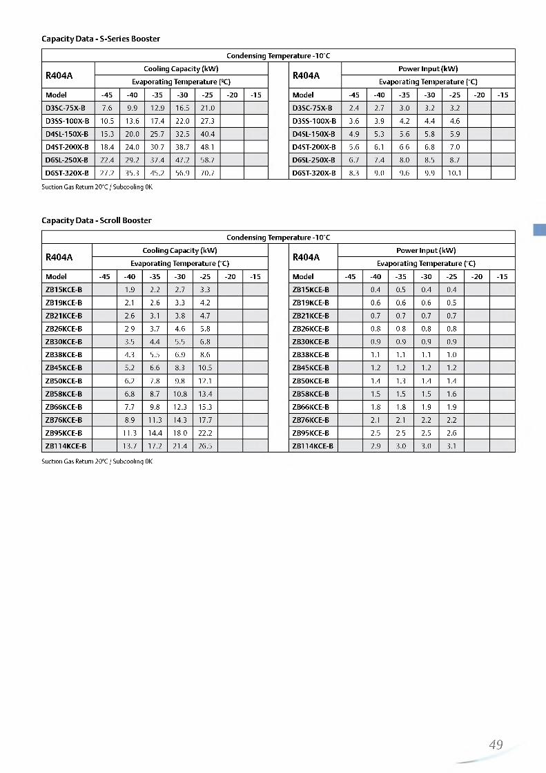
http://holodko.ru/
Capacity Data - S-Series Booster
Condensing Tem perature -10°C
R404ACooling Capacity (kW )
R404APow er Input (kW )
Evaporating Tem perature °C) Evaporating Tem perature <°C)
Model -45 -40 -35 -30 -25 - 2 0 -15 Model -45 -40 -35 -30 -25 - 2 0 -15
D3SC-75X-B 7.6 9.9 12.9 16.5 2 1 . 0 D3SC-75X-B 2.4 2.7 3.0 3.2 3.2
D3SS-100X-B 10.5 13.6 17.4 2 2 . 0 27.3 D3SS-100X-B 3.6 3.9 4.2 4.4 4.6
D4SL-150X-B 15.3 2 0 . 0 25.7 32.5 40.4 D4SL-150X-B 4.9 5.3 5.6 5.8 5.9
D4ST-200X-B 18.4 24.0 30.7 38.7 48.1 D4ST-200X-B 5.6 6 .1 6 .6 6 .8 7.0
D6SL-250X-B 22.4 29.2 37.4 47.2 58.7 D6SL-250X-B 6.7 7.4 8 .0 8.5 8.7
D6ST-320X-B 27.2 35.3 45.2 56.9 70.7 D6ST-320X-B 8.3 9.0 9.6 9.9 1 0 . 1
Suction Gas Return 20°C / Subcooling 0K
Capacity Data - Scroll Booster
Condensing Tem perature -10°C
R404ACooling Capacity (kW )
R404APow er Input (kW )
Evaporating Tem perature (°C) Evaporating Tem perature (°C)
Model -45 -40 -35 -30 -25 - 2 0 -15 Model -45 -40 -35 -30 -25 - 2 0 -15
ZB15KCE-B 1.9 2 . 2 2.7 3.3 ZB15KCE-B 0.4 0.5 0.4 0.4
ZB19KCE-B 2 . 1 2 . 6 3.3 4.2 ZB19KCE-B 0 .6 0 .6 0 .6 0.5
ZB21KCE-B 2 . 6 3.1 3.8 4.7 ZB21KCE-B 0.7 0.7 0.7 0.7
ZB26KCE-B 2.9 3.7 4.6 5.8 ZB26KCE-B 0 .8 0 .8 0 .8 0 .8
ZB30KCE-B 3.5 4.4 5.5 6 .8 ZB30KCE-B 0.9 0.9 0.9 0.9
ZB38KCE-B 4.3 5.5 6.9 8 .6 ZB38KCE-B 1 . 1 1 . 1 1 . 1 1 . 0
ZB45KCE-B 5.2 6.6 8.3 10.5 ZB45KCE-B 1 . 2 1 . 2 1 . 2 1 . 2
ZB50KCE-B 6 . 2 7.8 9.8 1 2 . 1 ZB50KCE-B 1.4 1.3 1.4 1.4
ZB58KCE-B 6 .8 8.7 1 0 . 8 13.4 ZB58KCE-B 1.5 1.5 1.5 1 . 6
ZB6 6 KCE-B 7.7 9.8 12.3 15.3 ZB6 6 KCE-B 1 . 8 1 . 8 1.9 1.9
ZB76KCE-B 8.9 11.3 14.3 17.7 ZB76KCE-B 2 . 1 2 . 1 2 . 2 2 . 2
ZB95KCE-B 11.3 14.4 18.0 2 2 . 2 ZB95KCE-B 2.5 2.5 2.5 2 . 6
ZB114KCE-B 13.7 17.2 21.4 26.5 ZB114KCE-B 2.9 3.0 3.0 3.1
Suction Gas Return 20°C / Subcooling 0K
49

http://holodko.ru/
Semi-Hermetic Reciprocating Compr
Emerson Climate Technologies offers different ranges of semi- hermetic reciprocating compressors with distinct levels of performance and technical characteristics depending on the application requirements.
BRAND CHANGE
Brand ChangeTo harmonize Emerson's semi-hermetic compressor ranges in terms of color and branding, Emerson is changing the product brand and the nomenclature of the semi-hermetic compressors for the K & L-Series and the Discus-range. In the future, we will start using the well-known ‘Copeland brand products' label replacing “DWM Copeland” and change the compressor color from grey to black.
By this initiative, all compressor products from Emerson with both scroll and piston technology are using one and the same branding and color: Copeland™ brand products - painted in black. Our customers can better focus their marketing and communications efforts leading to improved brand and company recognition.
Over time, our product range will be streamlined to only one compressor model line. The reed valve compressors of the 2- to 8-cylincer S-series will gradually be replaced by the puck design valve compressors of our Stream and Discus series. This results in reduced inventory lines at our distribution partners. Emerson Climate Technologies will provide you with a full model list to support you in the transition phase.
The S-Series:Its design is based on traditional “ reed” valve plates similar to what is used in reciprocating compressors offered by other manufacturers. The
S-Senes6 Cylinder performance of such compressors
meets basic market requirements but cannot compete with Discus compressors in terms of efficiency. The S-Series ranges from 1.5 to 70 hp and is composed of K, L, 2S, 3S, 4S and 8S presented in this catalogue.
The Discus Range:It is broadly recognized as the most efficient compressor whatever the running condition. This range is mainly used in refrigeration medium and low temperature applications where system efficiency is a priority for the end-user.The key difference between Discus and other reciprocating compressors lies in its valve plate design. Traditional “reed” valves are replaced by ‘puck” type valves that are integrated in the Discus 2 Cylinder
valve plate. This special design eliminates the dead volume at the
50
end of the compression and allows for the highest compressor efficiency. To date, no other reciprocating compressor is able to match Discus in terms of performance. Available from 4 to 60 hp, they are referred to as 2D, 3D, D4D, D6D and 8D in this catalogue.
The Stream Series:Emerson Climate Technologies has introduced Stream, a brand new line of semi-hermetic 4 and 6 cylinder compressors. The series provides best in class performance for today's HFC-based and uprising natural and low GWP refrigerants, significantly reducing cost of operation and environmental impact compared to competing products.
The range is made of 4 and 6 cylinder models, available for inverter applications, and 4 and 6 cylinder digital models for continuous capacity modulation. The compressors can be fitted with a dedicated sound shell for sound sensitive applications.
The new Emerson Climate Technologies line-up of 4 cylinder compressors for CO2-transcritical applications is the ideal solution for R744 medium temperature cascade and booster systems. It is characterised by a design pressure of 135 bar. Refrigerant flow and heat transfer have been optimized for best performance. In combination with the CO2-subcritical scroll for the low temperature refrigeration side, Emerson Climate Technologies offers the most energy efficient package available on the market today.
With advanced protection and diagnostics features for system reliabilty, reduced service costs and increased equipment uptime, the Stream series is built to last in today's modern changing world.
Stream Digital 4 Cylinder
\r S ■ j SStream 4 Cylinder for R744
Stream Digital 6 Cylinder
Sound Shell for Stream

http://holodko.ru/
Emerson CoreSense™ Diagnostics for Refrigeration
Emerson CoreSense Diagnostics is an innovative technology for Copeland Stream refrigeration compressors. It goes beyond compressor protection by assisting in system diagnosis and optimization. Providing service engineers with detailed information at the right time, system-related problems can be diagnosed faster or even before they occur. Supermarket operators benefit from increased system uptime, reduction in food loss and reduced maintenance costs.
Technical SpecificationPower supply 120/240V AC, 24V AC Front end: 2 x LED, green/red, yellow Communication protocol (Modbus®RTU)Bus to system controller: RS 485, 3-wire, (+ ,GND,-) Discharge temperature sensor Current sensor and sensor module Flash memory Alarm reset button IP 54
Benefits• Reduce applied system costs• Manage on-site compressor data• Facilitate predictive maintenance &
advanced diagnostics• Reduce maintenance costs• Increase system uptime / reduce food loss• Power consumption monitoring
Emerson CoreSense Diagnostics for Refrigeration. Ensuring Best Performance over Full Lifetime.
Functions
Modbus®Communication
to system controller
Motor and Oil protection
MemoryAsset, runtime and alarm information
Sensor ModuleCurrent sensing, voltage imbalance, phase loss monitoring
Status LEDs
CompressorPower
Monitoring
DischargeTemperatureProtection
Scope of Supply
Discharge Temperature Sensor
CoreSense™ Diagnostics Control Module
Current Sensor
Oil Pressure SensorSensor Module
Motor Temperature Sensor
51

http://holodko.ru/
K and L Reciprocating Compressor RangeSmall 2-cylinder semi-hermetic reciprocating compressors for medium and low temperature refrigeration applications and transport refrigeration.
Designed on the principle of standard reed valve type technology, these compressors feature an internal oil pump that guarantees optimum reliability in all operating conditions.
The K-series ranges from 0.5 to 2 hp and the L-series from 2 to 4 hp and provide cooling capacities from 1.5 to 9 kW in medium temperature (R404A, -10/45°C) and 0.5 to 3.5kW in low temperature (R404A, -35/40°C).
These compressors are qualified for R404A, R507, R134a and R22.
K-Series compressorK & L Compressor Line-up
L-Series • • • • • 1
K-Series • • • • •
D isp lacem ent (m 3/h) 1 I I0 2 4 6 8 10 12 14 16 18 20 22 24
Conditions EN12900, R404A: Evaporating -10°C, Condensing 40°C, Suction Gas Temperature 20°C, Subcooling 0K
Features and Benefits
• Large operating envelope from 5°C to -45°C evaporating and up to 55°C condensing
• Two motor sizes per displacement, optimized for different applications
• Compact and light compressors• Ideal for condensing unit or transport applications• Integrated oil pump for maximum reliability
Maximum Allowable Pressure (PS)
• Low Side PS 22.5 bar (g)/ High Side PS 28 bar (g)
Operating Envelope R404A
70
60
50
40
30
c 20
10
0
---------- I------
------
------
------
------
------
------
------
---/ t
/ / r 111111
-60 -55 -50 -45 -40 -35 -30 -25 -20 -15 -10 -5 0 5 10 15
Evaporating Temperature °C
Small Motor Large Motor
52

http://holodko.ru/
Technical Overview
R404ANo
min
alhp
Disp
lace
men
t(m
3/h)
Capa
city
(kW)
1)
POC Ca
pacit
y(kW
) 2)
COP
2)
Oil Q
uant
ity
(l)
Length/Width/Height(mm)
Net
Wei
ght
(kg)
Motor Version / Code
Maximum Operating Cur
rent (A)Locked Rotor Current (A)
Soun
d Pr
essu
re
@1
m (d
BA)
**
3 Ph* 3 Ph* 3 Ph*
KM-7X 0.8 4.0 1.8 1.9 0.65 365/235/280 39 EWL 2.4 1 2 . 2 45
KJ-10X 1 .0 5.1 2.5 1.9 0.65 365/235/280 39 EWL 3 16 45
KSJ-15X 1.5 6.3 3.2 1.9 0.65 365/235/280 40 EWL 3 20 53
KL-20X 2.0 7.4 3.7 2.1 0.65 365/235/280 39 EWL 4 20
KSL-20X 2.0 9.1 4.6 1.9 0.65 365/235/280 40 EWL 5 20
LE-20X 2.0 9.9 4.6 2.2 2.00 470/330/385 78 EWL 6 38 51
LF-30X 3.0 12.9 6.5 2.2 2.00 470/330/385 80 EWL 7 53 51
LJ-30X 3.0 14.5 7.2 2.1 2.00 470/330/385 83 EWL 8 53 52
LL-40X 4.0 18.2 9.2 2.2 2.00 470/330/385 87 EWL 10 69 63
KM-5X 0.5 4.0 0.6 1. 1 0.65 365/235/280 39 EWL 2 1 2 45
KJ-7X 0.8 5.1 0.8 1. 1 0.65 365/235/280 39 EWL 2 1 2 45
KSJ-10X 1 .0 6.3 1 .0 1 .1 0.65 365/235/280 40 EWL 3 16 50
KL-15X 1.5 7.4 1 .2 1 .2 0.65 365/235/280 39 EWL 3 20 47
LF-20X 2.0 12.9 1 .6 1 .1 2.00 470/330/385 80 EWL 5 38 51
LJ-20X 2.0 14.5 1.9 1 .2 2.00 470/330/385 78 EWL 6 38 52
LL-30X 3.0 18.2 2.6 1.3 2.00 470/330/385 85 EWL 7 53 52
LSG-40X 4.0 22.5 3.5 1.4 2.00 470/330/385 77 EWL 9 69 63
(1) MT= Conditions EN12900 : Evaporating -10°C, Condensing 45°C, Suction Gas Temperature 20°C, Subcooling 0K(2) LT= Conditions EN12900 : Evaporating -35°C, Condensing 40°C, Suction Gas Temperature 20°C, Subcooling 0K* 3 Ph: 380-420V/ 50Hz** @ 1 m: sound pressure level at 1 m distance from the compressor, free field condition
53

http://holodko.ru/
Capacity Data
Condensing Temperature 40°C
R404ACooling Capacity (kW )
R404APow er Input (kW )
Evaporating Tem perature (°C) Evaporating Tem perature (°C)
Model -45 -35 -30 - 2 0 - 1 0 -5 5 Model -45 -35 -30 - 2 0 - 1 0 -5 5
KM -5X 0 . 2 0 .6 0 .8 1.3 KM -5X 0.3 0.5 0 .6 0.7
KM -7X 0 . 2 0.5 0 .8 1.3 2 . 0 2.5 3.6 KM -7X 0.3 0.5 0 .6 0 .8 0.9 0.9 1 . 0
KJ-10X 0.3 0.7 1 . 0 1 . 8 2 . 8 3.4 4.9 KJ-10X 0.4 0.7 0 .8 1 . 0 1 . 2 1.3 1.4
KJ-7X 0.4 0 .8 1 . 1 1 . 8 KJ-7X 0.5 0.7 0 .8 1 . 0
KSJ-10X 0.5 1 . 0 1.4 2.3 KSJ-10X 0.7 0.9 1 . 1 1.3
KSJ-15X 0.5 1 . 0 1.4 2.3 3.5 4.2 6 . 1 KSJ-15X 0 .6 0.9 1 . 0 1.3 1 . 6 1.7 1 . 8
KL-15X 0 .6 1 . 2 1 . 6 2 . 6 KL-15X 0 .8 1 . 0 1 . 2 1.5
KL-20X 0.4 1 . 1 1.5 2 . 6 4.1 5.0 KL-20X 0 .6 0.9 1 . 1 1.4 1.7 1 . 8
KSL-20X 0.7 1.5 2 . 0 3.3 5.1 6 .1 KSL-20X 0 .8 1 . 2 1.4 1.9 2.3 2.5
LE-20X 1 . 1 1.7 3.2 5.1 6.4 9.4 LE-20X 1 . 0 1 . 2 1 . 6 2 . 0 2 . 2 2.5
LF-20X 1 . 6 2.3 4.0 LF-20X 1.4 1.7 2 . 2
LF-30X 0.7 1.9 2 . 6 4.6 7.2 8 .8 1 2 . 8 LF-30X 1 . 0 1 . 6 1.9 2.4 2.9 3.1 3.4
LJ-20X 1.9 2 . 8 5.0 LJ-20X 1 . 6 1.9 2 . 6
LJ-30X 0 .8 2 . 1 2.9 5.1 8 .0 9.8 14.2 LJ-30X 1 . 1 1 . 8 2 . 1 2 . 8 3.3 3.6 3.9
LL-30X 0.9 2 . 6 3.7 6.5 LL-30X 1 . 1 2 . 0 2.4 3.3
LL-40X 1 . 1 2.7 3.7 6.4 1 0 . 2 1 2 . 6 18.4 LL-40X 1.4 2 . 2 2 . 6 3.3 4.0 4.3 4.8
LSG-40X 1.4 3.5 4.8 8 . 2 LSG-40X 1 . 6 2 . 6 3.1 4.1
Suction Gas Return 20°C / subcooling 0KHigh Discharge Temp - Additional cooling required
Condensing Temperature 40°C
R134aCooling Capacity (kW)
R134aPower Input (kW)
Evaporating Temperature (°C) Evaporating Temperature (°C)
Model -30 -2 0 - 1 0 -5 5 10 15 Model -30 - 2 0 - 1 0 -5 5 1 0 15
KM-5X 0.7 1 .2 1.5 2.3 2.8 KM-5X 0.5 0.6 0.6 0.6 0.7
KJ-7X 0.9 1.6 2.0 3.0 3.7 KJ-7X 0.6 0.7 0.7 0.8 0.9
KSJ-10X 1 .2 2.0 2.5 3.8 4.6 KSJ-10X 0.7 0.8 0.9 1.0 1.0
KL-15X 1.4 2.3 2.8 4.3 5.2 KL-15X 0.8 1 .0 1 . 1 1.3 1.3
KSL-15X 1.7 2.8 3.5 5.3 6.5 KSL-15X 1.0 1.3 1.4 1.6 1.7
KSL-20X 1.7 2.9 3.7 5.6 6.7 KSL-20X 1.0 1 .2 1.4 1.6 1.6
LE-20X 1.5 2.8 3.6 5.6 6.9 LE-20X 1.0 1.3 1.4 1.5 1.6
LF-20X 2. 2 3.8 4.9 7.5 9.1 LF-20X 1 .2 1 .6 1.7 1.9 2.0
LJ-20X 2.6 4.3 5.4 8.3 10.1 LJ-20X 1.6 1.9 2.1 2.4 2.5
LL-30X 3.2 5.5 7.0 10.9 13.2 LL-30X 1.9 2.4 2.6 3.0 3.1
LSG-40X 4.3 7.2 9.0 13.7 16.6 LSG-40X 2.3 2.9 3.2 3.7 3.9
Suction Gas Return 20°C / Subcooling 0KHigh Discharge Temp - Additional cooling required
54
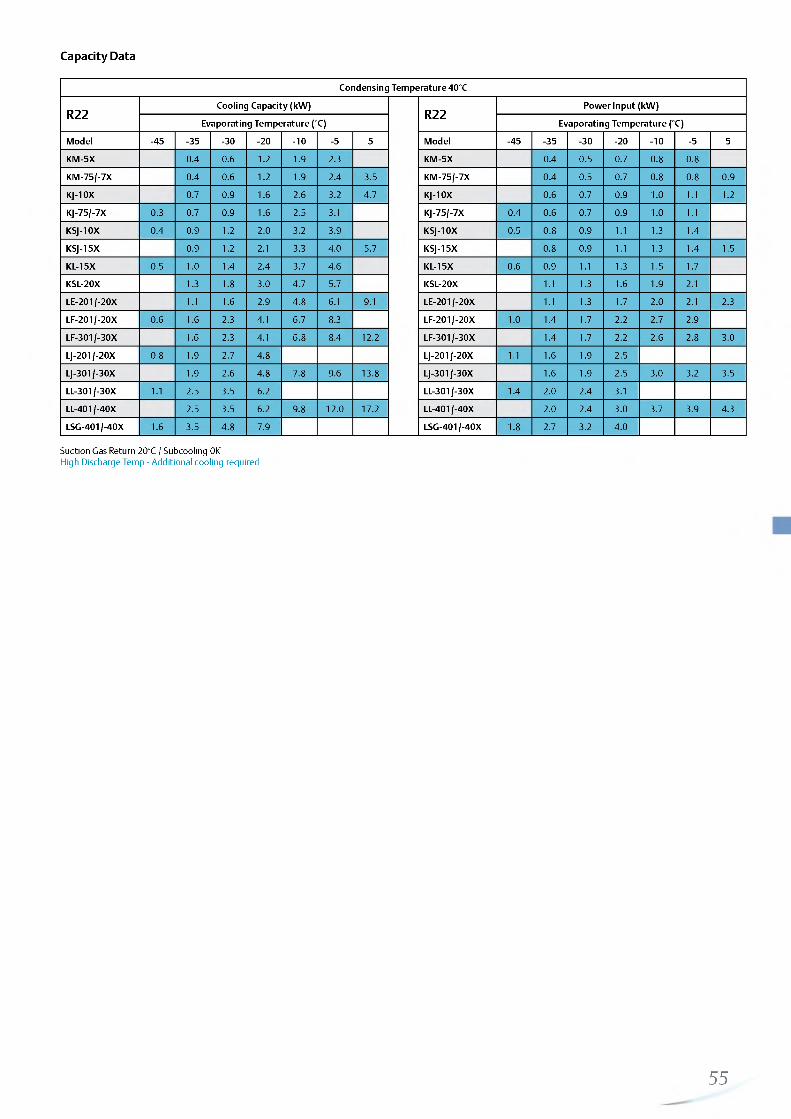
http://holodko.ru/
Capacity Data
Condensing Temperature 40°C
R22Cooling Capacity (kW)
R22Power Input (kW)
Evaporating Temperature (°C) Evaporating Temperature (°C)
Model -45 -35 -30 - 2 0 - 1 0 -5 5 Model -45 -35 -30 -2 0 - 1 0 -5 5
KM-5X 0.4 0.6 1 .2 1.9 2.3 KM-5X 0.4 0.5 0.7 0.8 0.8
KM-75/-7X 0.4 0.6 1 . 2 1.9 2.4 3.5 KM-75/-7X 0.4 0.5 0.7 0.8 0.8 0.9
KJ-10X 0.7 0.9 1 .6 2.6 3.2 4.7 KJ-10X 0.6 0.7 0.9 1 .0 1 . 1 1 .2
KJ-75/-7X 0.3 0.7 0.9 1 .6 2.5 3.1 KJ-75/-7X 0.4 0.6 0.7 0.9 1.0 1 . 1
KSJ-10X 0.4 0.9 1 .2 2.0 3.2 3.9 KSJ-10X 0.5 0.8 0.9 1.1 1.3 1.4
KSJ-15X 0.9 1 .2 2.1 3.3 4.0 5.7 KSJ-15X 0.8 0.9 1.1 1.3 1.4 1.5
KL-15X 0.5 1. 0 1.4 2.4 3.7 4.6 KL-15X 0.6 0.9 1 .1 1.3 1.5 1.7
KSL-20X 1.3 1 .8 3.0 4.7 5.7 KSL-20X 1 .1 1.3 1.6 1.9 2.1
LE-201/-20X 1 . 1 1.6 2.9 4.8 6.1 9.1 LE-201/-20X 1 .1 1.3 1.7 2.0 2.1 2.3
LF-201/-20X 0.6 1 .6 2.3 4.1 6.7 8.3 LF-201/-20X 1 .0 1.4 1.7 2.2 2.7 2.9
LF-301/-30X 1.6 2.3 4.1 6.8 8.4 1 2 . 2 LF-301/-30X 1.4 1.7 2.2 2.6 2.8 3.0
LJ-201/-20X 0.8 1.9 2.7 4.8 LJ-201/-20X 1 .1 1 .6 1.9 2.5
LJ-301/-30X 1.9 2.6 4.8 7.8 9.6 13.8 LJ-301/-30X 1 .6 1.9 2.5 3.0 3.2 3.5
LL-301/-30X 1 .1 2.5 3.5 6.2 LL-301/-30X 1.4 2.0 2.4 3.1
LL-401/-40X 2.5 3.5 6.2 9.8 1 2 . 0 17.2 LL-401/-40X 2.0 2.4 3.0 3.7 3.9 4.3
LSG-401/-40X 1 .6 3.5 4.8 7.9 LSG-401/-40X 1 .8 2.7 3.2 4.0
Suction Gas Return 20°C / Subcooling 0KHigh Discharge Temp - Additional cooling required
55

http://holodko.ru/
Discus™ Reciprocating Compressor RaFrom 2 to 8 cylinder semi-hermetic reciprocating compressors for medium / low temperature refrigeration applications.
The key difference between Discus and traditional reciprocating technologies lies in the valve plate design. The Discus valve plate allows gas to flow into the cylinders with a minimum heat gain, while suction cavities are designed to smoothly route the gas to minimize losses. These effects lead to:• Superior cooling capacity due to no re-expansion volume• Up to 10% higher efficiency compared to conventional “cost-
effective” reed type compressors• Lower operating costs for the end-user
The Discus ranges from 5 to 60 hp and provide cooling capacities from 8 to 96 kW in medium temperature (R404A, -10/45°C) and 2 to 35 kW in low temperature (R404A, -35/40°C). These compressors are qualified for R404A, R507, R134a and R22. All Discus compressors are designed to deliver maximum performance and reliability:• Discus “puck” valve integrated into the valve plate for
highest performance whatever the operating condition• Positive displacement high flow oil pump guarantees high oil
feeding pressure for good lubrication and bearings' cooling
nge
Discus compressor
PTFE coated bearings for especially low friction and goodprotection at start upElectronic motor protection moduleAvailability of two motor sizes per displacement. The smallmotor covers all refrigeration applications while the largemotor can be used in comfort or inverter applications
Discus Compressor Line-up
8 D-Series I * • I
D6 D-Series • •
D4D-Series• • •
3D-Series • • •
2D-Series
D isp lacem ent (m 3/h)0 10 20 30 40 50 60 70 80 90 100 110 120 130 140 150 160 170 180 190 200
Conditions: EN12900, R404A: Evaporating -10°C, Condensing 40°C, Suction Gas Temperature 20°C, Subcooling 0K
Features and Benefits
• Highest level of efficiency available on the market, whatever the refrigerant and operating condition
• Integrated oil pump and Electronic Oil Pressure Switch OPS2 for maximum reliability
• Two motor sizes per displacement, optimized for different applications
• Large operating envelope that allows medium and low temperature applications to be covered by one single model with condensing limit as low as 5°C
• Provide cooling capacity modulation either by cylinder head blocked suction or with use of frequency inverters from 25 to 60Hz
• Multi-refrigerant compressor range - one model to cover all standard refrigerants
Maximum Allowable Pressure (PS)
• Low Side PS 22.5 bar (g)/ High Side PS 28 bar (g)
Refer to Emerson’s Select 7.7 selection software for individual model operating envelopes and other refrigerants.
Operating Envelope R404A
Evaporating Temperature °C
Large Motor 25°C SGRT Large Motor 25°C SGRT + FanSmall Motor 25°C SGRT Small Motor 0°C SGRT + Fan
56

http://holodko.ru/
Technical Overview
R404ANo
min
alhp
Disp
lace
men
t(m
3/h)
Capa
city
(kW)
1)
POC Ca
pacit
y(kW
) 2)
COP
2)
Oil Q
uant
ity
(l)
Length/Width/Height(mm)
Net
Wei
ght
(kg)
Motor Version / Code
Maximum Operating Current (A)
Locked Rotor Current
(A)
Soun
d Pr
essu
re
@1
m (d
BA)
**
3 Ph* 3 Ph* 3 Ph*
2DC-50X 5.0 16.8 7.9 2.3 2.1 1 .2 2.30 590/330/470 132 AWM 9 55 65
2DD-50X 5.0 19.3 9.7 2.4 2.8 1.3 2.30 590/330/470 132 AWM 10 55 65
2DL-40X 4.0 23.7 1 2 . 0 2.3 3.8 1.4 2.30 590/330/470 131 AWM 1 1 55 64
2DL-75X 7.5 23.7 1 2 . 2 2.4 3.6 1.3 2.30 590/330/470 136 AWM 14 70 66
2DB-50X 5.0 28.0 14.6 2.3 4.6 1.4 2.30 590/330/470 131 AWM 13 55 64
2DB-75X 7.5 28.0 14.9 2.4 5.0 1.5 2.30 590/330/470 136 AWM 16 70 66
3DA-50X 5.0 32.2 16.3 2.2 5.7 1.4 3.70 655/370/480 146 AWM 16 55 69
3DA-75X 7.5 32.2 17.2 2.4 5.2 1.3 3.70 680/370/480 152 AWM 18 106 70
3DC-100X 10 .0 38.0 20.6 2.5 6.5 1.4 3.70 680/370/480 164 AWM 21 1 2 1 70
3DC-75X 7.5 38.0 19.8 2.3 7.0 1.4 3.70 655/370/480 150 AWM 18 70 71
3DS-100X 10 .0 49.9 27.1 2.3 9.6 1.5 3.70 680/370/480 162 AWM 24 1 2 1 71
3DS-150X 15.0 49.9 27.5 2.3 9.1 1.4 3.70 710/370/490 166 AWM 29 129 71
8DH-500X 50.0 151.0 81.7 2.4 26.3 1.4 7.60 835/475/610 330 AWM 88 458 79
8DL-370X 37.0 151.0 81.4 2.3 28.0 1.4 7.60 835/475/610 323 AWM 74 349 77
8DJ-600X 60.0 181.0 98.0 2.3 32.7 1.4 7.60 835/475/610 331 AWM 108 476 80
8DT-450X 45.0 181.0 96.0 2.3 34.7 1.5 7.60 835/475/610 335 AWM 91 441 78
Previous Generation - Replacement by Stream compressors
D4DF-100X 10 .0 56.0 29.1 2.3 9.7 1.4 3.30 680/535/605 179 AWM 27 105 76
D4DA-200X 20.0 56.0 30.2 2.4 9.2 1.4 3.30 650/535/495 196 AWM 33 175 72
D4DH-250X 25.0 70.8 38.6 2.4 1 2 . 2 1.4 3.30 670/535/495 209 AWM 42 199 72
D4DL-150X 15.0 70.8 38.4 2.3 13.1 1.4 3.30 680/535/605 205 AWM 35 156 77
D4DT-220X 22 .0 84.7 46.5 2.3 16.2 1.5 3.30 700/535/795 215 AWM 43 175 78
D4DJ-300X 30.0 84.7 46.6 2.3 15.4 1.4 3.30 690/535/495 214 AWM 53 2 2 1 74
D6DH-350X 35.0 160.0 56.6 2.3 18.7 1.4 3.30 760/580/490 246 AWM 64 304 76
D6DL-270X 27.0 106.0 54.4 2.2 19.0 1.4 3.30 740/580/490 242 AWM 54 199 80
D6DJ-400X 40.0 127.0 68.1 2.3 22.3 1.4 6.80 760/580/545 261 AWM 83 304 76
D6DT-320X 30.0 127.0 66.2 2.2 23.6 1.4 6.80 740/580/700 261 AWM 62 255 81
(1) MT= Conditions EN12900 : Evaporating -10°C, Condensing 45°C, Suction Gas Temperature 20°C, Subcooling 0K(2) LT= Conditions EN12900 : Evaporating -35°C, Condensing 40°C, Suction Gas Temperature 20°C, Subcooling 0K* 3 Ph: 380-420V/ 50Hz** @ 1 m: sound pressure level at 1 m distance from the compressor, free field condition
57

http://holodko.ru/
Capacity Data
Condensing Temperature 40°C
R404ACooling Capacity (kW)
R404APower Input (kW)
Evaporating Temperature (°C) Evaporating Temperature (°C)
Model -45 -35 -30 -2 0 - 1 0 -5 5 Model -45 -35 -30 - 2 0 - 1 0 -5 5
2DC-50X 2.1 3.0 5.4 8.8 1 1 . 0 16.5 2DC-50X 1.7 2.1 2.7 3.3 3.6 3.8
2DD-50X 2.8 3.9 6.8 10 .8 13.2 19.3 2DD-50X 2.2 2.5 3.3 3.9 4.1 4.3
2DL-40X 1 .2 * 3.8 5.1 8.5 13.2 16.2 2DL-40X 1 .8 * 2.7 3.2 4.1 4.9 5.3
2DL-75X 3.6 4.9 8.4 13.4 16.5 24.1 2DL-75X 2.7 3.1 4.0 4.8 5.1 5.5
2DB-50X 1.7* 4.6 6.2 10.4 16.0 19.4 2DB-50X 2 .2 * 3.2 3.8 4.9 5.9 6.3
2DB-75X 5.0 6.6 10.7 16.4 20.0 28.8 2DB-75X 3.4 3.9 5.0 5.9 6.3 6.9
3DA-50X 2 .0 * 5.7 7.4 11.9 17.9 21.7 3DA-50X 2.7* 4.0 4.7 5.9 6.9 7.3
3DA-75X 5.2 7.2 1 2 . 2 18.9 23.1 33.4 3DA-75X 3.9 4.6 5.9 6.9 7.3 7.6
3DC-100X 6.5 8.9 14.7 22.7 27.6 39.7 3DC-100X 4.5 5.3 6.8 7.9 8.4 8.7
3DC-75X 2 .8 * 7.0 9.1 14.4 2 1 . 6 26.1 3DC-75X 3.4* 4.9 5.6 7.0 8.2 8.7
3DS-100X 4.0* 9.6 12.5 19.8 29.5 35.5 3DS-100X 4.7* 6.5 7.5 9.4 1 1 . 1 11.7
3DS-150X 9.1 1 2 . 2 19.9 30.2 36.5 51.9 3DS-150X 6.3 7.4 9.4 1 1 . 1 1 1 . 6 1 2 . 0
8DH-500X 26.3 35.7 58.8 89.3 108.0 153.5 8DH-500X 19.1 22 .1 27.9 32.8 34.7 37.3
8DL-370X 1 0 .8 * 28.0 36.9 59.3 88.8 106.5 8DL-370X 13.2* 19.5 22.4 27.9 32.7 34.7
8DJ-600X 32.7 44.0 71.3 107.0 128.5 181.0 8DJ-600X 23.0 26.8 33.7 39.5 41.9 45.5
8DT-450X 14.2* 34.7 44.9 70.6 105.0 125.5 8DT-450X 16.9* 23.7 27.2 34.0 40.2 42.8
Previous Generation - Replacement by Stream compressors
D4DF-100X 3.5* 9.7 12 . 8 20.9 32.0 38.7 D4DF-100X 4.4* 6.8 8.0 10 .2 1 2 . 0 12.7
D4DA-200X 9.2 1 2 . 8 2 1 . 6 33.2 40.4 57.9 D4DA-200X 6.5 7.8 10 .1 11.9 1 2 . 6 13.3
D4DH-250X 1 2 . 2 16.6 27.6 42.4 51.6 73.9 D4DH-250X 8.8 10.3 13.1 15.4 16.3 17.5
D4DL-150X 5.1* 13.1 17.2 27.6 41.7 50.5 D4DL-150X 6 .2 * 9.1 10.5 13.3 15.6 16.6
D4DT-220X 6 .6 * 16.3 2 1 . 2 33.7 50.7 61.1 D4DT-220X 7.7* 1 1 . 2 13.0 16.2 19.0 20.1
D4DJ-300X 15.4 20.7 33.8 51.0 61.5 86.9 D4DJ-300X 10 .6 12.5 15.9 18.8 19.9 21.4
D6DL-270X 7.5* 19.1 24.8 39.7 59.8 72.1 D6DL-270X 9.2* 13.6 15.7 19.8 23.4 24.9
D6DH-350X 18.8 25.2 41.0 61.9 74.7 106.0 D6DH-350X 13.0 15.3 19.5 22.9 24.2 26.1
D6DJ-400X 22.3 30.0 49.1 74.8 90.7 130.0 D6DJ-400X 15.8 18.6 23.7 28.0 29.9 32.8
D6DT-320X 9.0* 23.6 30.9 48.9 72.3 86.2 D6DT-320X 11.3* 16.4 18.9 23.6 27.9 29.8
Suction Gas Return 20°C / Subcooling 0K *Suction Superheat 10K / Subcooling 0K High Discharge Temp - Additional cooling required
Condensing Temperature 40°C
R407CCooling Capacity (kW)
R407CPower Input (kW)
Evaporating Temperature (°C) Evaporating Temperature (°C)
Model -30 -2 0 - 1 0 -5 5 1 0 15 Model -30 -2 0 - 1 0 -5 5 1 0 15
2DC-50X 4.1 7.4 9.6 15.1 18.5 2DC-50X 2.1 2.7 2.9 3.3 3.3
2DD-50X 4.9 8.7 1 1 . 2 17.4 21.3 2DD-50X 2.5 3.1 3.4 3.8 3.9
2DL-75X 6.3 10.9 13.9 21.5 26.2 2DL-75X 3.1 3.9 4.2 4.8 4.9
2DB-75X 8.3 13.5 16.9 25.4 30.7 2DB-75X 3.9 4.7 5.1 5.7 5.8
3DA-75X 9.2 15.4 19.5 29.9 36.3 3DA-75X 4.5 5.5 5.9 6.4 6.5
3DC-100X 11.3 18.5 23.2 35.3 42.7 3DC-100X 5.3 6.4 6.9 7.6 7.7
3DS-150X 15.8 24.8 30.8 46.0 55.4 3DS-150X 7.4 8.8 9.4 10.3 10.5
8DH-500X 40.0* 70.6 88.9 135.0 163.5 8DH-500X 2 2 .0 * 26.6 28.7 31.8 32.5
8DJ-600X 47.9* 84.6 106.5 162.0 195.5 8DJ-600X 25.9* 31.8 34.6 39.2 40.6
Previous Generation - Replacement by Stream compressors
D4DA-200X 17.2 28.0 34.9 52.3 63.1 D4DA-200X 7.7 9.4 10.3 11.4 11.7
D4DH-250X 22.7 35.7 44.5 66.3 79.2 D4DH-250X 10.9 1 2 . 6 13.5 15.0 15.5
D4DJ-300X 26.5 41.2 50.8 74.8 89.6 D4DJ-300X 12.9 15.7 17.0 19.2 20.0
D6DH-350X 33.6 53.1 66.0 98.4 118.0 D6DH-350X 15.6 19.0 20.5 2 2 .8 23.3
D6DJ-400X 38.9 61.8 77.0 115.5 138.5 D6DJ-400X 18.5 22 .8 24.9 28.1 29.1
Suction Gas Return 20°C / Subcooling 0K *Suction Superheat 10K / Subcooling 0K
58

http://holodko.ru/
Capacity Data
Condensing Temperature 40°C
R134aCooling Capacity (kW)
R134aPower Input (kW)
Evaporating Temperature (°C) Evaporating Temperature (°C)
Model -30 -2 0 - 1 0 -5 5 1 0 15 Model -30 -2 0 - 1 0 -5 5 10 15
2DC-50X 2.4* 4.7* 6.3* 10.3 12.7 15.4 2DC-50X 1 .6 * 2 .0 * 2 .1 * 2.3 2.3 2.3
2DD-50X 3.1* 5.8* 7.6* 1 2 . 2 15.0 18.1 2DD-50X 1.9* 2.3* 2.5* 2.7 2.7 2.6
2DL-40X 4.0 7.2 9.2 14.4 17.6 2DL-40X 2.3 2.8 3.1 3.4 3.5
2DL-75X 3.6* 6 .8 * 8.9* 14.3 17.5 2 1 . 2 2DL-75X 2 . 1 * 2.7* 3.0* 3.3 3.4 3.4
2DB-50X 5.2 9.1 1 1 . 6 17.9 2 1 . 8 2DB-50X 2.6 3.3 3.6 4.0 4.1
2DB-75X 4.5* 8 .2 * 1 0 .6 * 17.0 20.7 25.0 2DB-75X 2 .6 * 3.3* 3.5* 3.9 4.0 4.0
3DA-50X 6.0 10 .2 12.9 19.8 24.1 3DA-50X 3.0 3.7 4.0 4.4 4.5
3DA-75X 5.1* 9.6* 12.5* 20.1 24.5 29.7 3DA-75X 3.1* 3.8* 4.1* 4.5 4.6 4.5
3DC-100X 6 .8 * 1 2 .0 * 15.3* 24.2 29.5 35.6 3DC-100X 3.7* 4.5* 4.8* 5.2 5.2 5.2
3DC-75X 7.4 12.5 15.7 23.9 29.0 3DC-75X 3.6 4.5 4.8 5.3 5.4
3DS-100X 9.7 16.2 20.4 31.0 37.5 3DS-100X 4.7 5.9 6.4 7.2 7.4
3DS-150X 9.7* 16.3* 2 0 .6 * 31.7 38.3 45.8 3DS-150X 5.0* 6 .2 * 6 .6 * 7.3 7.4 7.3
8DH-500X 28.6* 47.9* 60.9* 95.6 116.5 140.5 8DH-500X 15.5* 18.8* 2 0 .2 * 22 .2 22.7 22.9
8DL-370X 31.4 51.6 64.5 97.3 117.5 8DL-370X 15.1 18.5 19.9 22 .2 22 .8
8DJ-600X 34.4* 57.5* 72.9* 114.0 138.0 166.5 8DJ-600X 18.1* 2 2 .2 * 24.0* 26.8 27.7 28.2
8DT-450X 38.7 62.1 77.1 115.0 139.0 8DT-450X 18.4 22.5 24.4 27.5 28.5
Previous Generation - Replacement by Stream compressors
D4DF-100X 1 1 . 2 18.6 23.4 35.7 43.4 D4DF-100X 5.5 6.6 7.1 7.9 8.1
D4DA-200X 1 1 .0 * 18.6* 23.6* 36.6 44.3 53.2 D4DA-200X 5.1* 6.4* 7.0* 7.9 8.2 8.4
D4DH-250X 13.5* 22.9* 29* 44.9 54.4 65.2 D4DH-250X 7.0* 8.7* 9.4* 10.4 10.6 10 .6
D4DL-150X 15.0 24.5 30.5 45.7 55.2 D4DL-150X 7.0 8.7 9.4 10.5 10.9
D4DJ-300X 16.5* 27.8* 35.1* 54.3 65.7 78.9 D4DJ-300X 8.3* 10.4* 11.4* 13.2 14.0 14.5
D4DT-220X 18.4 29.7 37.0 55.4 66.9 D4DT-220X 8.6 10.5 11.4 12.7 13.1
D6DH-350X 19.8* 33.5* 42.5* 66.2 80.3 96.6 D6DH-350X 10.4* 13.1* 14.3* 16.0 16.5 16.6
D6DL-270X 21.4 35.7 44.9 68.1 82.5 D6DL-270X 10 .1 12.5 13.6 15.4 15.9
D6DJ-400X 24.6* 40.5* 50.9* 78.5 94.7 113.5 D6DJ-400X 1 2 .2 * 15.3* 16.9* 19.6 20.6 2 1 . 2
D6DT-320X 26.8 43.2 53.7 80.1 96.5 D6DT-320X 12.7 15.6 16.9 19.1 19.9
Suction Gas Return 20°C / Subcooling 0K *Suction Superheat 10K / Subcooling 0K
59

http://holodko.ru/
Capacity Data
Condensing Temperature 40°C
R22Cooling Capacity (kW)
R22Power Input (kW)
Evaporating Temperature (°C) Evaporating Temperature (°C)
Model -45 -35 -30 -2 0 - 1 0 -5 5 Model -45 -35 -30 -2 0 - 1 0 -5 5
2DC-50X 4.9 8.4 10 .6 15.9 2DC-50X 2.4 2.9 3.1 3.4
2DD-50X 5.8 9.8 12.3 18.4 2DD-50X 2.8 3.4 3.6 3.9
2DL-400 DC 1.4 3.1 4.3 7.4 11.7 2DL-400 DC 1.7 2.5 2.9 3.7 4.4
2DL-75X 7.4 12 .2 15.2 22.7 2DL-75X 3.5 4.2 4.5 4.9
2DB-500 DC 1.9 4.0 5.4 9.1 14.2 2DB-500 DC 2.3 3.2 3.6 4.5 5.2
2DB-75X 9.5 15.0 18.4 26.7 2DB-75X 4.3 5.1 5.4 5.8
3DA-500 DC 2.1 4.5 6.0 10 .1 3DA-500 DC 2 .2 3.4 4.0 5.0
3DA-75X 10.7 17.3 21.4 31.6 3DA-75X 5.0 5.9 6.3 6.6
3DC-750 DC 2.7 5.4 7.3 12.5 3DC-750 DC 2.8 4.0 4.7 6.1
3DC-100X 12.9 20 .6 25.4 37.2 3DC-100X 5.9 7.0 7.4 7.8
3DS-1000 DC 3.4 7.5 10 .2 17.2 3DS-1000 DC 3.9 5.7 6.6 8.4
3DS-150X 17.7 27.4 33.4 48.3 3DS-150X 8.1 9.4 10 .0 10 .6
8DH-500X 48.4* 79.3 97.6 143.0 8DH-500X 24.6* 28.9 30.7 33.1
8DJ-600X 58.0* 95.1 117.0 171.5 8DJ-600X 29.2* 34.8 37.3 41.0
Previous Generation - Replacement by Stream compressors
D4DF-1000 DC 3.8 7.8 10.5 17.4 D4DF-1000 DC 3.7 5.8 6.8 8.8
D4DA-200X 20.1 31.3 38.2 55.5 D4DA-200X 8.7 10.4 1 1 .0 11.9
D4DL-1500 DC 6.0 1 1 .6 15.2 23.6 D4DL-1500 DC 5.9 8.5 9.8 1 2 .2
D4DH-250X 25.7 39.5 48.1 69.3 D4DH-250X 11.5 13.6 14.4 15.6
D4DT-2200 DC 7.6 13.9 17.9 28.2 D4DT-2200 DC 7.2 10 .0 11.5 14.3
D4DJ-300X 30.7 46.4 56.2 80.4 D4DJ-300X 13.9 16.5 17.7 19.5
D6DH-350X 38.4 59.0 71.9 103.5 D6DH-350X 17.5 20.5 2 1 .8 23.6
D6DL-2700 DC 7.5 15.0 19.9 32.1 D6DL-2700 DC 8.0 1 1 .8 13.7 17.0
D6DT-3200 DC 9.7 18.7 24.4 37.8 D6DT-3200 DC 10 .0 14.4 16.6 20 .1
D6DJ-400X 44.6 69.0 84.3 1 2 2 .0 D6DJ-400X 20.8 24.9 26.7 29.3
Suction Gas Return 20°C / Subcooling 0K *Suction Superheat 10K / Subcooling 0K High Discharge Temp - Additional cooling required
60—

http://holodko.ru/
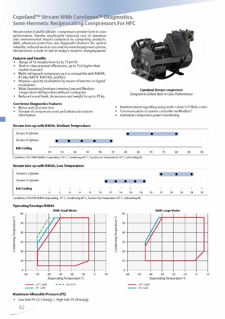
http://holodko.ru/
Copeland™ Stream With CoreSense™ Diagnostics, Semi-Hermetic Reciprocating Compressors For HFCStream series 4 and 6 cylinder compressors provide best-in-class performance, thereby significantly reducing cost of operation and environmental impact compared to competing products. With advanced protection and diagnostics features for system reliabilty, reduced service costs and increased equipment uptime, Stream series is built to last in today's modern changing world.
Features and Benefits• Range of 16 models from 62 to 153m3/h• Best-in-class seasonal efficiencies, up to 15% higher than
market standard• Multi-refrigerant compressor as it is compatible with R404A,
R134a, R407F, R407A/C and R22• Stepless capacity modulation by means of inverter or Digital
modulation• Wide Operating Envelope covering Low and Medium
Temperature Refrigeration without cooling fan• Reduced sound level, dimensions and weight by up to 45 kg
CoreSense Diagnostics Features• Motor and oil protection• Storage of compressor asset and advanced runtime
information
Stream Line-up with R404A, Medium Temperature
Copeland Stream compressorDesigned to Deliver Best-in-Class Performance
• Runtime/alarm signalling using multi-colour LED flash-codes• Communication to system controller via Modbus®• Individual compressor power monitoring
Stream 6 Cylinder • • •
Stream 4 Cylinder • • • • •
kW Cooling I I I 130 35 40 45 50 55 60 65 70 75 80 85 90
Conditions: EN12900 R404A: Evaporating -10° C, Condensing 45° C, Suction Gas Temperature 20° C, Subcooling 0K
Stream Line-up with R404A, Low Temperature
Stream 6 Cylinder • • •
Stream 4 Cylinder • • • • •
kW Cooling 1 1 1 1 1 1 10 2 4 6 8 10 12 14 16 18 20 22 24 26 28 30
Conditions: EN12900 R404: Evaporating -35° C, Condensing 40° C, Suction Gas Temperature 20° C, Subcooling 0K
Operating Envelope R404AW ith Sm all M otor
25°C SGRT 0°C SGRT
Evaporating Temperature °C
- - - SH <20°C
Maximum Allowable Pressure (PS)
• Low Side PS 22.5 bar(g) / High Side PS 28 bar(g)
62
W ith Large M otor
Evaporating Temperature °C
25°C SGRT 0°C SGRT
__—

http://holodko.ru/
Technical Overview
R404ANo
min
al hp
Disp
lacem
ent
(m3/
h)
Capa
city
(kW)
1)
POC Ca
pacit
y(kW
) 2)
COP
2)
Oil Q
uant
ity
Length/Width/Height
(mm)
Net
Weig
ht (
kg)
Mot
or V
ersion
/
Code
Maxim
um
Ope
rati
ng
Curre
nt (
A)
Lock
ed
Roto
r Cu
rrent
(A)
Soun
d Pr
essu
re
@1m
(dBA
)**
3Ph* 3Ph* 3Ph* 1 ) 2 )4MF-13X 13 62 31.6 2.3 10.7 1.4 3.3 638/501/452 177 AWM 30.8 105 68 70
4MA-22X 22 62 32.7 2.4 10.5 1.4 3.3 638/501/452 177 AWM 36.3 175 68 75
4ML-15X 15 71 38.4 2.3 13.3 1.5 3.3 638/501/452 180 AWM 35.4 156 69 71
4MH-25X 25 71 38.5 2.4 12.4 1.4 3.3 657/501/452 187 AWM 41.6 199 69 75
4MM-20X 17 78 42.0 2.3 15.1 1.5 3.3 657/501/452 182 AWM 39.0 175 70 71
4MI-30X 27 78 42.8 2.4 14.4 1.5 3.3 657/501/452 188 AWM 46.6 2 2 1 70 75
4MT-22X 22 88 47.6 2.3 17.0 1.5 3.3 657/501/452 183 AWM 44.5 175 71 73
4MJ-33X 33 88 47.6 2.4 16.2 1.5 3.3 657/501/452 190 AWM 52.9 2 2 1 71 74
4MU-25X 25 99 53.1 2.3 18.6 1.4 3.3 657/501/452 186 AWM 51.9 199 73 72
4MK-35X 32 99 53.5 2.3 18.3 1.4 3.3 688/501/452 20 2 AWM 61.1 255 72 74
6MM-30X 27 12 0 64.2 2.3 22.7 1.4 3.3 695/547/450 215 AWM 59.7 255 72 78
6MI-40X 35 12 0 64.6 2.3 21.9 1.4 3.3 695/547/450 219 AWM 71.4 304 72 78
6MT-35X 32 135 72.4 2.3 25.6 1.5 3.3 725/547/450 22 1 AWM 67.3 255 73 77
6MJ-45X 40 135 72.4 2.3 24.3 1.4 3.3 725/547/450 223 AWM 81.5 304 74 79
6MU-40X 40 153 81.4 2.3 28.4 1.4 3.3 757/547/450 225 AWM 75.8 304 75 78
6MK-50X 50 153 80.9 2.3 27.3 1.4 3.3 773/547/450 230 AWM 92.9 393 76 80
1) MT = Conditions EN12900 : Evaporating -10°C, Condensing 45°C, Suction Gas Temperature 20°C, Subcooling 0K2) LT = Conditions EN12900 : Evaporating -35°C, Condensing 40°C, Suction Gas Temperature 20°C, Subcooling 0K* 3 Ph: 380-420V/ 50Hz** @ 1 m: sound pressure level at 1 m distance from the compressor, free field condition
Capacity Data
Condensing Temperature: 40°C
R404ACooling Capacity (kW)
R404APower Input (kW)
Evaporating Temperature (°C) Evaporating Temperature (°C)
Model -45 -35 -30 -2 0 - 1 0 -5 5 Model -45 -35 -30 -2 0 -1 0 -5 5
4MA-22X 10.5 14.3 23.6 36.0 43.5 62.0 4MA-22X 7.3 8.6 1 1 .0 13.0 13.7 14.7
4MF-13X 3.6* 10.7 14.1 22 .8 34.8 42.2 4MF-13X 5.0* 7.4 8.7 1 1 .0 13.1 13.9
4MH-25X 12.4 16.7 27.5 42.2 51.3 73.6 4MH-25X 8.6 10 .1 13.0 15.4 16.3 17.5
4ML-15X oo4. 13.3 17.4 27.9 42.0 50.8 4ML-15X 6.3* 9.0 10.5 13.3 15.8 16.7
4MI-30X 14.4 19.4 31.2 46.8 56.3 79.5 4MI-30X 9.8 11.5 14.5 17.0 18.0 19.5
4MM-20X 5.7* 15.1 19.6 30.9 46.1 55.4 4MM-20X 7.1* 10 .1 1 1 .6 14.6 17.1 18.2
4MJ-33X 16.2 21.4 34.6 52.4 63.4 90.4 4MJ-33X 10.9 12 .6 16.1 19.0 20 .2 2 1 .8
4MT-22X 6.7* 17.0 21.9 34.7 52.0 62.7 4MT-22X
o8. 11.5 13.2 16.6 19.5 20.7
4MK-35X 18.3 24.0 38.8 58.9 71.3 10 2 .0 4MK-35X 12 .6 14.6 18.5 2 2 .0 23.5 25.7
4MU-25X 7.2* 18.6 24.1 38.5 58.1 70.2 4MU-25X
o9. 12.9 14.9 18.8 22.3 23.7
6MI-40X 21.9 28.9 46.7 70.8 85.8 122.5 6MI-40X 15.2 17.6 2 2 .2 26.1 27.7 30.1
6MM-30X 8.9* 22.7 29.3 46.5 70.2 85.1 6MM-30X 1 1 .0 * 15.7 18.1 22.5 26.3 27.8
6MJ-45X 24.3 32.3 52.5 79.5 96.1 136.5 6MJ-45X 16.8 19.6 24.9 29.5 31.4 33.9
6MT-35X 10.3* 25.6 33.0 52.5 79.3 95.9 6MT-35X 12.3* 17.5 20.1 25.3 29.7 31.5
6MK-50X 27.3 36.3 58.7 88.6 107.0 152.0 6MK-50X 19.4 22.5 28.3 33.5 35.9 39.9
6MU-40X 1 1 .0 * 28.4 36.8 58.7 89.0 108.0 6MU-40X 13.8* 19.7 22.7 28.5 33.6 35.8
Suction Gas Return 20°C, Subcooling 0K* Suction Superheat 10K, Subcooling 0K
63

http://holodko.ru/
Capacity Data
R134aCooling Capacity (kW)
R134aPower Input (kW)
Condensing Temperature: 40°C Condensing Temperature: 40°C
Evaporating Temperature (°C) Evaporating Temperature (°C)
Model -45 -35 -30 -2 0 -1 0 -5 5 Model -45 -35 -30 -2 0 - 1 0 -5 5
4MA-22X 11.9* 2 0 .2 * 25.7* 40.0 4MA-22X 5.9* 7.3* 7.9* 8.7
4MF-13X 12.3 20.4 25.6 38.9 4MF-13X 5.8 7.2 7.8 8.7
4MH-25X 13.6* 23.3* 29.6* 46.3 4MH-25X 7.1* 8.7* 9.4* 10.4
4ML-15X 15.0 24.5 30.5 46.0 4ML-15X 6.9 8.5 9.3 10.4
4MI-30X 15.3* 25.7* 32.5* 50.6 4MI-30X 7.6* 9.4* 10.3* 11.4
4MM-20X 16.6 27.0 33.6 50.3 4MM-20X 7.7 9.4 10 .2 11.4
4MJ-33X 17.2* 28.7* 36.3* 56.3 4MJ-33X 8.7* 10.7* 11.5* 12 .8
4MT-22X 19.1 30.6 38.1 57.2 4MT-22X 8.7 10 .8 11.7 13.1
4MK-35X 19.3* 32.2* 40.7* 63.1 4MK-35X 9.7* 1 2 .2 * 13.3* 14.9
4MU-25X 20.7 33.9 42.3 63.8 4MU-25X 9.8 1 2 .2 13.3 15.1
6MI-40X 22.4* 38.0* 48.3* 75.8 6MI-40X 1 2 .0 * 14.6* 15.8* 17.8
6MM-30X 25.2 40.7 50.7 76.1 6MM-30X 11.7 14.6 15.8 17.7
6MJ-45X 25.8* 43.1* 54.6* 85.1 6MJ-45X 13.0* 16.2* 17.8* 20.3
6MT-35X 28.5 46.0 57.1 85.2 6MT-35X 13.3 16.5 17.9 20.0
6MK-50X 26.5* 46.1* 59.2* 94.0 6MK-50X 15.2* 18.8* 20.5* 23.3
6MU-40X 31.5 50.6 62.9 94.5 6MU-40X 14.6 18.4 20.1 23.0
Suction Gas Return 20°C, Subcooling 0K* Suction Superheat 10K, Subcooling 0K
R407FCooling Capacity (kW)
R407FPower Input (kW)
Condensing Temperature: 40°C Condensing Temperature: 40°C
Evaporating Temperature (°C) Evaporating Temperature (°C)
Model -45 -35 -30 -2 0 - 1 0 -5 5 Model -45 -35 -30 -2 0 - 1 0 -5 5
4MA-22X 20.7* 34.8 43.0 63.8 4MA-22X 1 0 .2 * 12.4 13.2 14.4
4MH-25X 24.2* 40.4 49.9 73.8 4MH-25X 11.9* 14.4 15.4 16.8
4MI-30X 26.9* 44.4 54.8 80.7 4MI-30X 13.1* 15.8 17.0 18.6
4MJ-33X 30.2* 49.5 60.9 89.8 4MJ-33X 14.8* 17.8 19.2 2 1 . 1
4MK-35X 33.7* 55.3 68.3 1 0 1 .0 4MK-35X 16.8* 20.4 2 2 .1 24.4
6MI-40X 41.2* 67.9 83.5 122.5 6MI-40X 2 0 .2 * 24.4 26.2 28.9
6MJ-45X 45.8* 75.2 92.6 136.0 6MJ-45X 22.9* 27.6 29.7 32.8
6MK-50X 51.3* 84.5 104.0 153.5 6MK-50X 25.8* 31.3 33.7 37.5
Suction Gas Return 20°C, Subcooling 0K* Suction Superheat 10K, Subcooling 0K
64

http://holodko.ru/
Capacity Data
R22Cooling Capacity (kW)
R22Power Input (kW)
Condensing Temperature: 40°C Condensing Temperature: 40°C
Evaporating Temperature (°C) Evaporating Temperature (°C)
Model -45 -35 -30 -2 0 -1 0 -5 5 Model -45 -35 -30 -2 0 -1 0 -5 5
4MA-22X 2 2 .1 34.5 42.2 61.2 4MA-22X 9.6 11.5 1 2 .2 13.1
4MF-13X DC 4.2* 8 .6 * 11.5* 19.2* 4MF-13X DC 4.0* 6.4* 7.5* 9.7*
4MH-25X 25.9 39.8 48.4 69.9 4MH-25X 1 1 .6 13.7 14.5 15.7
4ML-15X DC 6 .0 * 11.7* 15.3* 23.7* 4ML-15X DC 5.9* 8.5* 9.8* 12.3*
4MI-30X 28.3 42.9 51.9 74.3 4MI-30X 12.9 15.3 16.3 18.0
4MM-20X DC 7.0* 1 2 .8 * 16.6* 26.0* 4MM-20X DC 6.7* 9.3* 1 0 .6 * 13.2*
4MJ-33X 31.8 48.1 58.2 83.3 4MJ-33X 14.4 17.1 18.3 20 .1
4MT-22X DC 7.8* 14.4* 18.6* 29.2* 4MT-22X DC 7.5* 10.4* 11.9* 14.8*
4MK-35X 36.0 54.5 66.0 94.4 4MK-35X 16.3 19.4 20.7 2 2 .8
4MU-25X DC 8.9* 16.3* 2 1 .0 * 33.1* 4MU-25X DC 8.5* 1 1 .8 * 13.5* 16.8*
6MI-40X 43.5 66.9 81.5 117.5 6MI-40X 19.8 23.3 24.7 26.7
6MJ-45X 47.4 73.4 89.5 129.5 6MJ-45X 2 2 .1 26.5 28.3 31.2
6MK-50X 53.7 83.2 101.5 147.0 6MK-50X 25.1 30.0 32.1 35.4
Suction Gas Return 20°C, Subcooling 0K* Suction Superheat 10K, Subcooling 0K Additionally Cooling required
65

http://holodko.ru/
Copeland™ Stream Digital with CoreSense™ Diagnostics for Continuous Capacity ModulationStream Digital series 4 and 6 cylinder compressors provide an alternative means of continuous modulation to inverter. Digital modulation is the most simple and precise method of capacity control and helps to contain applied costs associated with modulation.
Digital technology is based on controlling a high cycle solenoid valve fitted on one of the cylinder heads based on cycle time.The valve actuates a piston that controls the flow of gas into the suction area of the Stream valve plate.
The compressor always run at constant speed which resolves the challenges related to oil return, mechanical and electrical stress on the system.
All compressors are equipped with CoreSense technology and offer the possibility to diagnose system related problems faster or even before they occur.
Features and Benefits• Range of 16 Models from 62 to 153 m3/h• Multi-refrigerant compressor as it is compatible with R404A,
R407F, R407A/C, R134a and R22• Continuous modulation from 50-100% (4-cylinder) and
33-100% (6-cylinder) ensuring a perfect match of capacity and power to refrigeration load
• Economical and reliable alternative to frequency inverters• Precise suction pressure control with associated energy
savings and stable evaporating temperatures• Quick and easy integration into refrigeration equipment,
similar to any other standard compressor
Copeland Stream Digital compressor
• Possibility to easily retrofit existing installations with digital cylinder head kit
• No vibrations or mechanical stress on system piping and compressor parts
• Reduced compressor cycling for longer contactor and compressor life
• Emerson CoreSense Diagnostics technology providing advanced protection, diagnostics and preventive maintenance
Stream Digital Line-up with R404A, Medium Temperature
Stream 6 Cylinder • • •
Stream 4 Cylinder • • • • •
kW Cooling 1 1 1 1 1
30 35 40 45 50 55 60 65 70 75 80 85 90
Conditions: EN12900 R404A: Evaporating -10° C, Condensing 45° C, Suction Gas Temperature 20° C, Subcooling 0K
Stream Digital Line-up with R404A, Low Temperature
Stream 6 Cylinder • • •
Stream 4 Cylinder • • • • •
kW Cooling 1 1 1 1 1 1 10 2 4 6 8 220286420 24 26 28 30
Conditions: EN12900 R404: Evaporating -35° C, Condensing 40° C, Suction Gas Temperature 20° C, Subcooling 0K
66

http://holodko.ru/
Operating Envelope R404A
W ith Sm all M otor W ith Large M otor
Evaporating Temperature °C Evaporating Temperature °C
25°CSGRTat 100% modulation or0°CSGRT + Fan between 33% (6 cyl) or 50% (4 cyl) and 99% modulation 0°C SGRT at 100% modulation
— — — SH > 20°C at 100% modulation0°C SGRT between 33% (6 cyl) or 50% (4 cyl) and 99% modulation 25°C SGRT between 33% (6 cyl) or 50% (4 cyl) and 99% modulation
Technical Overview
R404A
Nom
inal
hp
Disp
lacem
ent
(m3/
h)
Capa
city
(kW)
1)
POC Ca
pacit
y(kW
) 2)
COP
2)
Oil Q
uant
ity
Length/Width/Height
(mm)
Net
Weig
ht (
kg)
Mot
or V
ersion
/
Code
Maxim
um
Ope
rat
ing
Curre
nt (
A)
Lock
ed
Roto
r Cu
rrent
(A)
Soun
d Pr
essu
re
@1m
(dBA
)**
3Ph* 3Ph* 3Ph* 1 ) 2 )
4MFD-13X 13 62 31.3 2.3 9.5 1.3 3.3 638/501/452 177 AWM 30.8 105 68 70
4MAD-22X 22 62 32.4 2.4 9.3 1.3 3.3 638/501/452 177 AWM 36.3 175 68 75
4MLD-15X 15 71 38.0 2.3 1 2 .1 1.3 3.3 638/501/452 180 AWM 35.4 156 69 71
4MHD-25X 25 71 38.1 2.4 1 1 . 1 1.3 3.3 657/501/452 187 AWM 41.6 199 69 75
4MMD-20X 17 78 41.6 2.3 13.7 1.4 3.3 657/501/452 182 AWM 39.0 175 70 71
4MID-30X 27 78 42.3 2.4 13.0 1.3 3.3 657/501/452 188 AWM 46.6 2 2 1 70 75
4MTD-22X 22 88 47.2 2.3 15.4 1.4 3.3 657/501/452 183 AWM 44.5 175 71 73
4MJD-33X 33 88 47.1 2.4 14.6 1.4 3.3 657/501/452 190 AWM 52.9 2 2 1 71 74
4MUD-25X 25 99 52.2 2.3 16.9 1.3 3.3 657/501/452 186 AWM 51.9 199 73 72
4MKD-35X 32 99 53.0 2.3 16.5 1.3 3.3 688/501/452 20 2 AWM 61.1 255 72 74
6MMD-30X 27 1 2 0 63.6 2.3 20 .6 1.3 3.3 695/547/450 215 AWM 59.7 255 72 78
6MID-40X 35 1 2 0 64.0 2.3 19.7 1.3 3.3 695/547/450 219 AWM 71.4 304 72 78
6MTD-35X 32 135 71.7 2.3 23.2 1.3 3.3 725/547/450 2 2 1 AWM 67.3 255 73 77
6MJD-45X 40 135 71.7 2.3 21.9 1.3 3.3 725/547/450 223 AWM 81.5 304 74 79
6MUD-40X 40 153 80.5 2.3 25.7 1.3 3.3 757/547/450 225 AWM 75.8 304 75 78
6MKD-50X 50 153 80.1 2.3 24.5 1.3 3.3 773/547/450 230 AWM 92.9 393 76 80
1) MT = Conditions EN12900 : Evaporating -10°C, Condensing 45°C, Suction Gas Temperature 20°C, Subcooling 0K2) LT = Conditions EN12900 : Evaporating -35°C, Condensing 40°C, Suction Gas Return Temperature 0°C, Subcooling 0K* 3 Ph: 380-420V/ 50Hz** @ 1 m: sound pressure level at 1 m distance from the compressor, free field condition
67
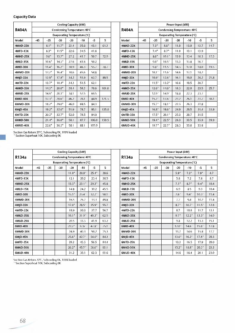
http://holodko.ru/
Capacity Data
R404ACooling Capacity (kW)
R404APower Input (kW)
Condensing Temperature: 40°C Condensing Temperature: 40°C
Evaporating Temperature (°C) Evaporating Temperature (°C)
Model -45 -35 -30 -2 0 - 1 0 -5 5 Model -45 -35 -30 -2 0 - 1 0 -5 5
4MAD-22X 8 . 1 * 11.7* 23.4 35.6 43.1 61.3 4MAD-22X 7.3* 8 .6 * 1 1 .0 13.0 13.7 14.7
4MFD-13X 8.3* 11.5* 22 .6 34.5 41.8 4MFD-13X 7.4* 8.7* 1 1 .0 13.1 13.9
4MHD-25X 9.6* 13.7* 27.2 41.7 50.7 72.9 4MHD-25X 8 .6 * 1 0 .1 * 13.0 15.4 16.3 17.5
4MLD-15X 1 0 .6 * 14.5* 27.6 41.6 50.2 4MLD-15X 9.0* 10.5* 13.3 15.8 16.7
4MID-30X 11.4* 16.2* 30.9 46.3 55.7 78.7 4MID-30X 9.8* 11.5* 14.5 17.0 18.0 19.5
4MMD-20X 1 2 .2 * 16.4* 30.6 45.6 54.8 4MMD-20X 1 0 . 1 * 1 1 .6 * 14.6 17.1 18.2
4MJD-33X 12.9* 17.8* 34.2 51.9 62.7 89.5 4MJD-33X 10.9* 1 2 .6 * 16.1 19.0 2 0 .2 2 1 .8
4MTD-22X 13.7* 18.4* 34.3 51.5 62.1 4MTD-22X 11.5* 13.2* 16.6 19.5 20.7
4MKD-35X 14.5* 2 0 .0 * 38.4 58.3 70.6 1 0 1 .0 4MKD-35X 1 2 .6 * 14.6* 18.5 22 .0 23.5 25.7
4MUD-25X 14.9* 2 0 .1 * 38.1 57.5 69.5 4MUD-25X 12.9* 14.9* 18.8 22.3 23.7
6MID-40X 17.3* 28.6* 46.2 70.1 84.9 121.5 6MID-40X 15.2* 17.6* 2 2 .2 26.1 27.7 30.1
6MMD-30X 18.2* 29.0* 46.0 69.5 84.3 6MMD-30X 15.7* 18.1* 22.5 26.3 27.8
6MJD-45X 19.2* 32.0* 51.9 78.7 95.1 135.0 6MJD-45X 16.8* 19.6* 24.9 29.5 31.4 33.9
6MTD-35X 20.5* 32.7* 52.0 78.5 94.9 6MTD-35X 17.5* 2 0 .1 * 25.3 29.7 31.5
6MKD-50X 21.4* 36.0* 58.1 87.7 106.0 150.5 6MKD-50X 19.4* 22.5* 28.3 33.5 35.9 39.9
6MUD-40X 2 2 .6 * 36.5* 58.1 88.1 107.0 6MUD-40X 19.7* 22.7* 28.5 33.6 35.8
Suction Gas Return 20°C, Subcooling 0K, 100% loaded* Suction Superheat 10K, Subcooling 0K
R134aCooling Capacity (kW)
R134aPower Input (kW)
Condensing Temperature: 40°C Condensing Temperature: 40°C
Evaporating Temperature (°C) Evaporating Temperature (°C)
Model -45 -35 -30 -2 0 - 1 0 -5 5 Model -45 -35 -30 -2 0 -1 0 -5 5
4MAD-22X 1 1 .8 * 2 0 .0 * 25.4* 39.6 4MAD-22X 5.9* 7.3* 7.9* 8.7
4MFD-13X 1 2 .1 20 .2 25.4 38.5 4MFD-13X 5.8 7.2 7.8 8.7
4MHD-25X 13.5* 23.1* 29.3* 45.8 4MHD-25X 7.1* 8.7* 9.4* 10.4
4MLD-15X 14.8 24.2 30.2 45.5 4MLD-15X 6.9 8.5 9.3 10.4
4MID-30X 15.1* 25.4* 32.2* 50.1 4MID-30X 7.6* 9.4* 10.3* 11.4
4MMD-20X 16.5 26.7 33.3 49.8 4MMD-20X 7.7 9.4 10 .2 11.4
4MJD-33X 17.0* 28.5* 35.9* 55.7 4MJD-33X 8.7* 10.7* 11.5* 12 .8
4MTD-22X 18.9 30.3 37.7 56.7 4MTD-22X 8.7 10 .8 11.7 13.1
4MKD-35X 19.1* 31.9* 40.3* 62.5 4MKD-35X 9.7* 1 2 .2 * 13.3* 14.9
4MUD-25X 20.5 33.5 41.9 63.2 4MUD-25X 9.8 1 2 .2 13.3 15.1
6MID-40X 2 2 .2 * 37.6* 47.8* 75.1 6MID-40X 1 2 .0 * 14.6* 15.8* 17.8
6MMD-30X 24.9 40.3 50.2 75.3 6MMD-30X 11.7 14.6 15.8 17.7
6MJD-45X 25.6* 42.7* 54.0* 84.3 6MJD-45X 13.0* 16.2* 17.8* 20.3
6MTD-35X 28.2 45.5 56.5 84.4 6MTD-35X 13.3 16.5 17.9 20.0
6MKD-50X 26.2* 45.7* 58.6* 93.1 6MKD-50X 15.2* 18.8* 20.5* 23.3
6MUD-40X 31.2 50.1 62.3 93.6 6MUD-40X 14.6 18.4 20.1 23.0
Suction Gas Return 20°C, Subcooling 0K, 100% loaded* Suction Superheat 10K, Subcooling 0K
68

http://holodko.ru/
Capacity Data
R407FCooling Capacity (kW)
R407FPower Input (kW)
Condensing Temperature: 40°C Condensing Temperature: 40°C
Evaporating Temperature (°C) Evaporating Temperature (°C)
All Preliminary Data
Model -45 -35 -30 -2 0 - 1 0 -5 5 Model -45 -35 -30 -2 0 -1 0 -5 5
4MAD-22X 20.5* 34.4 42.6 63.1 4MAD-22X 1 0 .2 * 12.4 13.2 14.4
4MHD-25X 23.9* 40.0 49.4 73.1 4MHD-25X 11.9* 14.4 15.4 16.8
4MID-30X 26.6* 44.0 54.2 79.9 4MID-30X 13.1* 15.8 17.0 18.6
4MJD-33X 29.8* 49.0 60.3 88.9 4MJD-33X 14.8* 17.8 19.2 2 1 . 1
4MKD-35X 33.3* 54.8 67.6 10 0 .0 4MKD-35X 16.8* 20.4 2 2 .0 24.4
6MID-40X 40.7* 67.2 82.6 121.5 6MID-40X 2 0 .2 * 24.4 26.2 28.9
6MJD-45X 45.3* 74.5 91.6 135.0 6MJD-45X 22.9* 27.6 29.7 32.8
6MKD-50X 50.7* 83.7 103.0 151.5 6MKD-50X 25.8* 31.3 33.7 37.5
Suction Gas Return 20°C, Subcooling 0K, 100% loaded* Suction Superheat 10K, Subcooling 0K
R22Cooling Capacity (kW)
R22Power Input (kW)
Condensing Temperature: 40°C Condensing Temperature: 40°C
Evaporating Temperature (°C) Evaporating Temperature (°C)
Model -45 -35 -30 -2 0 -1 0 -5 5 Model -45 -35 -30 -2 0 -1 0 -5 5
4MAD-22X 2 2 .1 34.5 42.1 61.2 4MAD-22X 9.6 11.4 1 2 .2 13.1
4MFD-13X DC 4.2 8.6 11.5 19.2 4MFD-13X DC 4.0 6.4 7.5 9.7
4MHD-25X 25.9 39.8 48.5 69.9 4MHD-25X 1 1 .6 13.64 14.5 15.7
4MLD-15X DC 6.0 1 1 .6 15.2 23.7 4MLD-15X DC 5.9 8.5 9.8 12.3
4MID-30X 28.3 42.9 51.9 74.3 4MID-30X 12 .8 15.2 16.3 18.0
4MMD-20X DC 7.0 12 .8 16.5 26.0 4MMD-20X DC 6.7 9.3 10 .6 13.2
4MJD-33X 31.8 48.1 58.2 83.3 4MJD-33X 14.4 17.1 18.3 20.1
4MTD-22X DC 7.8 14.4 18.5 29.2 4MTD-22X DC 7.8 10.4 1 1 .8 14.8
4MKD-35X 36.0 54.5 66.0 94.4 4MKD-35X 16.3 19.4 20.7 22 .8
4MUD-25X DC 8.9 16.3 2 1 .0 33.1 4MUD-25X DC 8.5 1 1 .8 13.4 16.8
6MID-40X 43.5 66.9 81.5 117.6 6MID-40X 19.8 23.3 24.7 26.7
6MMD-30X DC 9.2 17.7 23.1 35.8 6MMD-30X DC 9.4 13.7 15.7 19.1
6MJD-45X 47.4 73.4 89.5 129.6 6MJD-45X 2 2 .1 26.5 28.3 31.2
6MTD-35X DC 10.3 19.9 25.9 40.2 6MTD-35X DC 10 .6 15.3 17.6 21.4
6MKD-50X 53.7 83.2 101.5 147.0 6MKD-50X 25.1 30.0 32.1 35.4
6MUD-40X DC 11.7 22.5 29.4 45.5 6MUD-40X DC 1 2 .0 17.4 19.9 24.2
Suction Gas Return 20°C, Subcooling 0K, 100% loaded Additional Cooling required
69

http://holodko.ru/
Copeland™ Stream Compressors with CoreSense™ Diagnostics for R744-Transcritical ApplicationsStream series of 4 cylinder CO2 compressors is the ideal solution for R744 medium temperature cascade and booster systems. It is characterized by a design pressure of 135 bar. Refrigerant flow and heat transfer have been optimized for best performance. All compressors are equipped with CoreSense technology and offer the possibility to diagnose system-related problems faster or even before they occur.
Features and BenefitsStream provides for flexibility in pack design and operation:• Compact dimensions• Integrated high and low pressure relief valve• Discharge Temperature Protection• Service valve 360° rotation for ease of piping design• 2 sight glasses for mounting of oil management control and
visual inspection• One additional sight glass for oil visual inspection at run time• One oil port for oil equalization in parallel system• Oil splasher system ensuring lubrication at constant and
variable speed
Designed for durability and performance in R744 applications:• Low sound, low vibration and large discharge chamber to
eliminate pulsation• High design pressures of 135 bar (high side) and 90 bar
(low side)• Burst pressures in excess of safety factor 3• Cylinder head and discharge plenum design minimizing heat
transfer to suction side• Stepless capacity modulation via inverter from 30 to 70Hz• CoreSense™ Diagnostics• Individual compressor power consumption monitoring
Stream Line-up for R744
R744 • • •
kW Cooling 1 110 15 20 25 30 35 40
Conditions: EN12900 R744: Evaporating -10°C, Gas cooler exit: 35°C/ 90 bar, Superheat: 10K
Operating Envelope R744
130 -|---------- --------------
1 1 0
9 0 ------------------------------------------------------------------------------CDD£ 7 0 -------------------------------------------------------------------------------
CLQJCT
5 0 -------------------------------------------------------- 1 -------------------uO
3 0 ------------------------------------------------------
10 -|---------- ^ ^ ^ ^ ^ ^ -----------25 -20 -15 -10 -5 0 5 10
Evaporating Temperature °C
Copeland Stream Compressors for R744 Refrigeration Designed for Durability and Best-in-Class
Performance in R744 Transcritical Applications
70—

http://holodko.ru/
Technical Overview
R744
Nom
inal
hp
Disp
lace
men
t(m
3/h)
Capa
city
(kW
) Q_OC
Oil Q
uant
ity
(l)
Length/Width/Heigth(mm)
Net
Wei
ght
(kg)
Motor Version / Code
Maximum Operating Current (A)
Locked Rotor Current (A)
Soun
d Pr
essu
re
@1
m (d
BA)
**
3 Ph* 3 Ph* 3 Ph*
4MTL-12X 1 2 9.5 18.3 1.7 3.30 697/445/422 170 AWM 26 145 69
4MTL-15X 15 12.5 24.9 1.8 3.30 697/445/422 170 AWM 35 156 72
4MTL-30X 30 17.9 36.5 1.8 3.30 697/445/422 175 AWM 50 2 2 1 75
Conditions EN12900 R744: Evaporating -10°C, Gas cooler exit: 35°C/90bar, Superheat: 10K* 3 Ph: 380-420V/ 50Hz** @ 1 m: sound pressure level at 1 m distance from the compressor, free field condition
Capacity Data
Cooling capacity (kW) Power Input (kW)
Tem
pera
ture
(°C)
Pres
sure
(b
ar) Evaporating Temperature (°C) Evaporating Temperature (°C)
Model-2 0 -15 - 1 0 -5 0 -2 0 -15 - 1 0 -5 0
Equivalent evaporation pressure (bar) Equivalent evaporation pressure (bar)
19,7 22,9 26,5 30,5 34,9 19,7 22,9 26,5 30,5 34,9
10 45.0 2 2 .2 27.0 32.4 38.6 6.0 5.8 5.4 4.8
Cond
ensin
g 15 50.9 20 .2 24.6 29.6 35.3 41.6 6.7 6.6 6.3 5.9 5.2
20 57.3 18.2 22 .1 26.7 31.9 37.6 7.4 7.4 7.2 6.9 6.4
4MTL-12X25 64.3 15.9 19.4 23.4 28.0 33.1 8.0 8.2 8.2 8.0 7.6
30 75 12.7 15.6 18.9 22 .6 26.7 8.7 8.9 9.1 9.0 8.9
Gas
Cool
er 35 90 1 2 .1 14.8 18.0 2 1 .6 25.6 9.9 10.3 10.7 10 .8 10.9
40 10 0 10.4 13.1 16.0 19.3 22.9 10 .6 11.3 1 1 .8 1 2 .1 12.3
40 1 1 0 10.4 13.1 16.0 19.3 22.9 10 .6 11.3 1 1 .8 1 2 .1 12.3
10 45.0 30.3 36.8 44.1 52.4 7.67 7.44 6.98 6.26
Cond
ensin
g 15 50.9 27.6 33.6 40.4 48.1 56.5 8.54 8.46 8.17 7.63 6.81
20 57.3 24.8 30.2 36.4 43.4 51.1 9.4 9.47 9.35 8.99 8.37
4MTL-15X25 64.3 2 1 .6 26.4 31.9 38.1 45 10.25 10.45 10.5 10.35 9.93
30 75 17.3 2 1 .2 25.7 30.7 36.3 11.05 11.45 11.7 11.7 11.45
Gas
Cool
er 35 90 16.35 20 .1 24.5 29.3 34.5 12 .6 13.2 13.7 13.95 13.95
40 10 0 14.1 17.65 2 1 .6 26 30.8 13.5 14.45 15.1 15.55 15.8
40 1 1 0 14.1 17.65 2 1 .6 26 30.8 13.5 14.45 15.1 15.55 15.8
10 45.0 44.7 54.0 64.7 76.8 1 1 . 2 10.9 10.3 9.3
Cond
ensin
g 15 50.9 40.7 49.3 59.2 70.4 82.7 12.4 12.3 12 .0 11.3 10 .1
20 57.3 36.6 44.3 53.3 63.5 74.7 13.7 13.8 13.7 13.2 12.4
4MTL-30X25 64.3 32.0 38.8 46.8 55.8 65.8 14.9 15.2 15.3 15.1 14.6
30 75 25.6 31.2 37.7 45.0 53.0 16.1 16.7 17.0 17.1 16.8
Gas
Cool
er 35 90 24.4 29.7 35.9 42.9 50.6 18.3 19.2 19.9 20.3 20.4
40 10 0 2 1 . 1 26.3 32.0 38.3 45.3 19.6 2 1 .0 21.9 2 2 .6 23.0
40 1 1 0 2 1 . 1 26.3 32.0 38.3 45.3 19.6 2 1 .0 21.9 2 2 .6 23.0
71
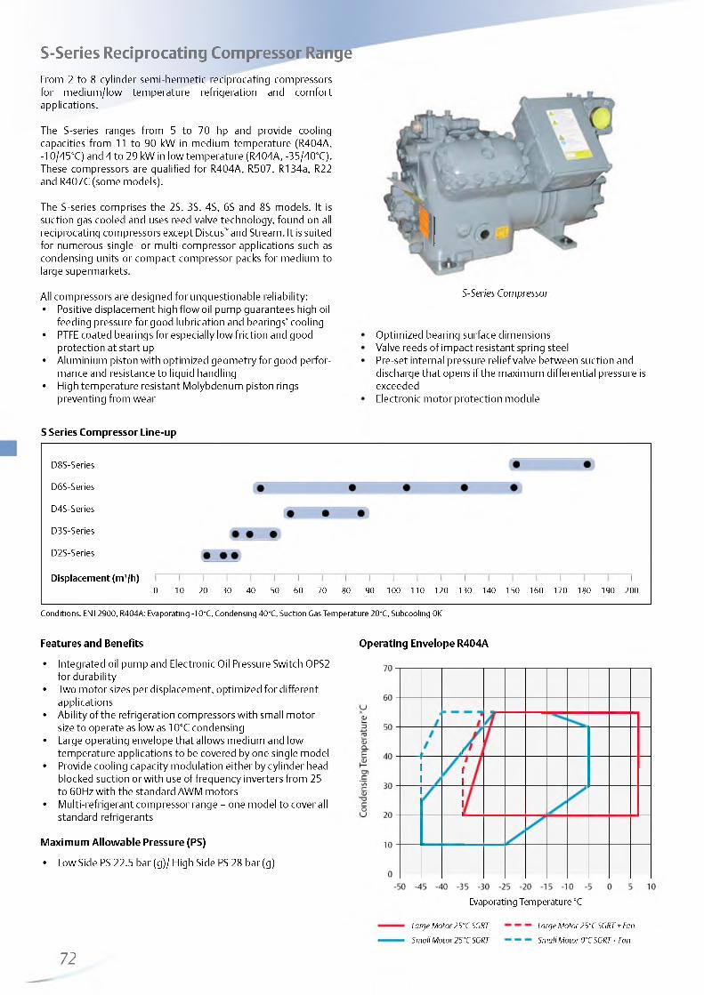
http://holodko.ru/
S-Series Reciprocating Compressor RaFrom 2 to 8 cylinder semi-hermetic reciprocating compressors for medium/low temperature refrigeration and comfort applications.
The S-series ranges from 5 to 70 hp and provide cooling capacities from 11 to 90 kW in medium temperature (R404A, -10/45°C) and 4 to 29 kW in low temperature (R404A, -35/40°C). These compressors are qualified for R404A, R507, R134a, R22 and R407C (some models).
The S-series comprises the 2S, 3S, 4S, 6S and 8S models. It is suction gas cooled and uses reed valve technology, found on all reciprocating compressors except Discus™ and Stream. It is suited for numerous single- or multi-compressor applications such as condensing units or compact compressor packs for medium to large supermarkets.
All compressors are designed for unquestionable reliability:• Positive displacement high flow oil pump guarantees high oil
feeding pressure for good lubrication and bearings' cooling• PTFE coated bearings for especially low friction and good
protection at start up• Aluminium piston with optimized geometry for good perfor
mance and resistance to liquid handling• High temperature resistant Molybdenum piston rings
preventing from wear
nge
S-Series Compressor
Optimized bearing surface dimensionsValve reeds of impact resistant spring steelPre-set internal pressure relief valve between suction anddischarge that opens if the maximum differential pressure isexceededElectronic motor protection module
S Series Compressor Line-up
D8 S-Series
D6 S-Series
D4S-Series
D3S-Series
D2S-Series
D isp lacem ent (m 3/h)0 10 20 30 40 50 60 70 80 90 100 110 120 130 140 150 160 170 180 190 200
Conditions: EN12900, R404A: Evaporating -10°C, Condensing 40°C, Suction Gas Temperature 20°C, Subcooling 0K
Features and Benefits
Integrated oil pump and Electronic Oil Pressure Switch OPS2 for durabilityTwo motor sizes per displacement, optimized for different applicationsAbility of the refrigeration compressors with small motor size to operate as low as 10°C condensing Large operating envelope that allows medium and low temperature applications to be covered by one single model Provide cooling capacity modulation either by cylinder head blocked suction or with use of frequency inverters from 25 to 60Hz with the standard AWM motors Multi-refrigerant compressor range - one model to cover all standard refrigerants
Maximum Allowable Pressure (PS)
• Low Side PS 22.5 bar (g)/ High Side PS 28 bar (g)
Operating Envelope R404A
Evaporating Temperature °C
72
Large Motor25°C SGRT Small Motor 25°C SGRT
Large Motor 25°C SGRT + Fan Small Motor 0°CSGRT+Fan

http://holodko.ru/
Technical Overview
R404ANo
min
alhp
Disp
lace
men
t(m
3/h)
Capa
city
(kW)
1)
POC Ca
pacit
y(kW
) 2) 2)
POC
Oil Q
uant
ity
(l)
Length/Width/Heigth(mm)
Net
Wei
ght
(kg)
Motor Version /
Code
Maximum Operating Current (A)
Locked Rotor Current (A)
Soun
d Pr
essu
re
@1
m (d
BA)
**
3 Ph* 3 Ph* 3 Ph*
D2SA-45X 4.5 22.4 1 1 . 1 2.0 3.5 1 .2 2.40 560/330/395 90 EWL 1 1 69
D2SA-55X 5.5 22.4 1 1 .2 2.0 2.40 560/330/395 90 EWL 13 67
D2SC-55X 5.5 26.8 13.4 2.0 4.1 1.3 2.40 560/330/395 91 EWL 13 74 67
D2SC-65X 6.5 26.9 13.3 2.0 2.40 560/330/395 91 EWL 16 85
D2SK-65X 6.5 31.2 15.9 2.0 4.9 1 .2 2.40 560/330/395 92 EWL 16 85
D3SA-75X 7.5 32.2 15.6 2 .2 3.70 655/370/480 159 AWM 18 82
D3SC-100X 10 .0 38.0 18.9 2 .2 3.70 682/370/480 159 AWM 22 106
D3SC-75X 10 .0 38.0 18.3 2 .1 5.5 1.3 3.70 655/370/480 159 AWM 19 82 66
D3SS-100X 10 .0 49.9 24.5 2.0 8.2 1.3 3.70 680/370/480 162 AWM 26 109 67
D3SS-150X 15.0 49.9 25.9 2 .1 3.70 680/370/480 162 AWM 30 125
D4SA-200X 20.0 56.0 27.5 2 .2 3.30 650/485/495 183 AWM 32 175 70
D4SF-100X 10 .0 56.0 27.3 2.1 8.9 1.3 3.30 680/485/495 178 AWM 27 105 72
D4SH-250X 25.0 70.8 35.1 2.1 3.30 670/490/495 194 AWM 42 199 71
D4SL-150X 15.0 70.8 36.4 2.1 11.9 1.4 3.30 680/490/495 186 AWM 36 156 72
D4SJ-300X 30.0 84.5 42.8 2.2 3.30 690/515/495 2 1 0 AWM 48 2 2 1 70
D4ST-200X 20.0 84.7 43.4 2.1 14.5 1.4 3.30 700/490/495 198 AWM 42 175 72
D6SA-300X 30.0 84.0 41.8 2.2 3.30 740/540/490 214 AWM 50 2 2 1 75
D6SF-200X 20.0 84.0 41.8 2.1 13.5 1.4 3.30 740/540/490 2 1 2 AWM 38 175
D6SJ-400X 40.0 127.0 62.7 2.2 6.80 760/565/545 252 AWM 75 304 74
D6ST-300X 32.0 127.0 21.3 1.4 6.80 740/540/545 252 AWM 63 255
D6ST-320X 32.0 127.0 1 1 . 1 2.1 21.3 1.4 6.80 740/540/545 252 AWM 63 255
D6SU-400X 40.0 151.8 1 1 . 1 2.1 26.6 1.4 6.80 740/540/545 265 AWM 78 304
D6SK-500X 50.0 152.0 73.1 2.1 6.80 770/570/539 268 AWM 89 393 78
D8SH-370X 37.0 151.0 1 1 . 1 2.1 24.6 1.4 7.60 835/467/610 314 AWM 71 349
D8SH-500X 50.0 151.0 78.2 2.2 7.60 835/467/610 326 AWM 95 458 77
D8SJ-450X 45.0 181.0 1 1 . 1 2.1 28.7 1.4 7.60 835/527/610 345 AWM 91 441
D8SJ-600X 60.0 181.0 90.4 2.2 7.60 835/527/610 346 AWM 106 476 76
(1) MT= Conditions EN12900 : Evaporating -10°C, Condensing 45°C, Suction Gas Temperature 20°C, Subcooling 0K(2) LT= Conditions EN12900 : Evaporating -35°C, Condensing 40°C, Suction Gas Temperature 20°C, Subcooling 0K* 3 Ph: 380-420V/ 50Hz** @ 1 m: sound pressure level at 1 m distance from the compressor, free field condition
73
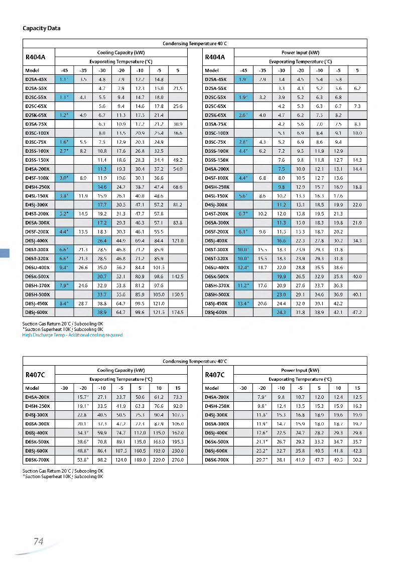
http://holodko.ru/
Capacity Data
Condensing Temperature 40°C
R404ACooling Capacity (kW)
R404APower Input (kW)
Evaporating Temperature (°C) Evaporating Temperature (°C)
Model -45 -35 -30 -2 0 - 1 0 -5 5 Model -45 -35 -30 -2 0 -1 0 -5 5
D2SA-45X 1 . 1 * 3.5 4.8 7.9 1 2 .2 14.8 D2SA-45X 1.9* 2.9 3.4 4.5 5.4 5.8
D2SA-55X 4.7 7.9 12.3 15.0 21.5 D2SA-55X 3.3 4.3 5.2 5.6 6.2
D2SC-55X 1 . 1 * 4.1 5.5 9.4 14.7 18.0 D2SC-55X 1.9* 3.2 3.9 5.2 6.3 6.8
D2SC-65X 5.6 9.4 14.6 17.8 25.6 D2SC-65X 4.2 5.3 6.3 6.7 7.3
D2SK-65X 1 .2 * 4.9 6.7 11.3 17.5 21.4 D2SK-65X 2 .6 * 4.0 4.7 6 .2 7.5 8.2
D3SA-75X 6.3 10.9 17.2 2 1 .2 30.9 D3SA-75X 4.2 5.6 7.0 7.5 8.3
D3SC-100X 8.0 13.5 20.9 25.4 36.6 D3SC-100X 5.3 6.9 8.4 9.1 10 .0
D3SC-75X 1 .6 * 5.5 7.5 12.9 20.3 24.9 D3SC-75X 2 .8 * 4.3 5.2 6.9 8.6 9.4
D3SS-100X 2.7* 8.2 10 .8 17.6 26.8 32.5 D3SS-100X 4.4* 6 .2 7.2 9.5 11.9 12.9
D3SS-150X 11.4 18.6 28.3 34.4 49.2 D3SS-150X 7.6 9.8 1 1 .8 12.7 14.3
D4SA-200X 11.3 19.3 30.4 37.2 54.0 D4SA-200X 7.5 10 .0 1 2 .1 13.1 14.4
D4SF-100X 3.0* 8.9 11.9 19.6 30.1 36.6 D4SF-100X 4.4* 6.8 8.0 10.5 12.7 13.6
D4SH-250X 14.6 24.7 38.7 47.4 68.6 D4SH-250X 9.8 12.9 15.7 16.9 18.8
D4SL-150X 3.8* 11.9 15.9 26.1 40.0 48.6 D4SL-150X 5.6* 8.6 10 .2 13.3 16.3 17.6
D4SJ-300X 17.7 30.5 47.1 57.2 81.2 D4SJ-300X 1 1 . 2 15.1 18.5 19.9 22 .0
D4ST-200X 5.2* 14.5 19.2 31.3 47.7 57.8 D4ST-200X 6.7* 10 .2 12 .0 15.8 19.5 21.3
D6SA-300X 17.2 29.3 46.3 57.1 83.8 D6SA-300X 11.3 15.0 18.3 19.8 21.9
D6SF-200X 4.4* 13.5 18.3 30.3 46.1 55.5 D6SF-200X 6 . 1 * 9.6 11.5 15.3 18.7 20 .2
D6SJ-400X 26.4 44.9 69.4 84.4 1 2 1 .0 D6SJ-400X 16.6 22.3 27.8 30.2 34.3
D6ST-300X 6 .6 * 21.3 28.5 46.8 71.2 85.9 D6ST-300X 1 0 .0 * 15.5 18.3 23.9 29.3 31.8
D6ST-320X 6 .6 * 21.3 28.5 46.8 71.2 85.9 D6ST-320X 1 0 .0 * 15.5 18.3 23.9 29.3 31.8
D6SU-400X 9.4* 26.6 35.0 56.2 84.4 101.5 D6SU-400X 12.4* 18.7 22 .0 28.8 35.5 38.6
D6SK-500X 30.7 52.1 80.9 98.6 142.5 D6SK-500X 19.9 26.5 32.9 35.8 40.0
D8SH-370X 7.9* 24.6 32.9 53.8 81.2 97.6 D8SH-370X 1 1 .2 * 17.6 20.9 27.6 33.7 36.3
D8SH-500X 33.7 55.6 85.9 105.0 150.5 D8SH-500X 23.0 29.1 34.6 36.9 40.1
D8SJ-450X 8.4* 28.7 38.8 64.7 99.5 1 2 1 .0 D8SJ-450X 13.4* 20.6 24.4 32.0 39.1 42.2
D8SJ-600X 38.9 64.7 99.6 121.5 174.5 D8SJ-600X 24.3 31.8 38.9 42.1 47.2
Suction Gas Return 20°C / Subcooling 0K *Suction Superheat 10K / Subcooling 0K High Discharge Temp - Additional cooling required
Condensing Temperature 40°C
R407CCooling Capacity (kW)
R407CPower Input (kW)
Evaporating Temperature (°C) Evaporating Temperature (°C)
Model -30 -2 0 -1 0 -5 5 10 15 Model -30 -2 0 - 1 0 -5 5 10 15
D4SA-200X 15.7* 27.1 33.7 50.6 61.2 73.3 D4SA-200X 7.9* 9.8 10.7 12 .0 12.4 12.5
D4SH-250X 19.1* 33.5 41.9 63.3 76.6 92.0 D4SH-250X 9.8* 12.4 13.5 15.3 15.9 16.3
D4SJ-300X 2 2 .8 * 40.5 50.5 75.3 90.4 107.5 D4SJ-300X 1 1 .8 * 15.3 16.8 18.9 19.6 19.9
D6SA-300X 2 0 . 1 * 37.3 47.2 72.3 87.9 106.0 D6SA-300X 11.9* 14.7 15.9 18.0 18.7 19.2
D6SJ-400X 34.3* 59.9 74.7 1 1 2 .0 135.0 162.0 D6SJ-400X 17.6* 22.5 24.7 28.2 29.3 29.8
D6SK-500X 38.6* 70.8 89.1 135.0 163.0 195.5 D6SK-500X 2 1 .1 * 26.7 29.2 33.2 34.7 35.7
D8SJ-600X 48.8* 86.4 107.5 160.5 193.0 230.0 D8SJ-600X 25.2* 32.7 35.8 40.5 41.8 42.3
D8SK-700X 53.8* 98.2 124.0 189.0 229.0 276.0 D8SK-700X 29.7* 38.1 41.9 47.7 49.5 50.2
Suction Gas Return 20°C / Subcooling 0K *Suction Superheat 10K / Subcooling 0K
74

http://holodko.ru/
Capacity Data
Condensing Temperature 40°C
R134aCooling Capacity (kW)
R134aPower Input (kW)
Evaporating Temperature (°C) Evaporating Temperature (°C)
Model -30 -2 0 -1 0 -5 5 10 15 Model -30 -2 0 -1 0 -5 5 10 15
D2SA-45X 4.2 7.0 8.9 13.7 16.8 D2SA-45X 2.5 3.0 3.3 3.6 3.7
D2SC-55X 5.2 8.5 10.7 16.2 19.7 D2SC-55X 2.9 3.6 4.0 4.5 4.6
D2SK-65X 5.7 9.5 12 .0 18.3 2 2 .2 D2SK-65X 3.3 4.2 4.5 5.1 5.4
D3SC-75X 6.9 11.3 14.3 22 .0 27.0 D3SC-75X 3.8 4.8 5.4 6.4 6.9
D3SS-100X 9.0 14.9 18.7 28.8 35.3 D3SS-100X 5.0 6.4 7.1 8.3 8.8
D4SA-100X 11.3 18.6 23.1 34.4 41.3 D4SA-100X 5.2 6.6 7.3 8.4 8.8
D4SF-100X 10.3 17.7 22.4 34.4 41.9 D4SF-100X 5.4 6.9 7.6 8.7 9.1
D4SH-150X 1 2 .2 21.5 27.4 42.3 51.5 D4SH-150X 6.3 8.2 9.0 10.3 10.5
D4SL-150X 13.6 23.0 29.0 44.1 53.6 D4SL-150X 6.8 8.7 9.6 1 1 . 2 1 1 .8
D4SJ-200X 17.0 28.0 34.9 52.1 62.6 D4SJ-200X 8.2 10.7 11.9 14.1 15.0
D4ST-200X 16.5 27.7 34.8 52.9 64.2 D4ST-200X 8.1 10.5 1 1 .6 13.6 14.3
D6SF-200X 16.1 27.2 34.4 52.6 63.8 D6SF-200X 7.9 10 .2 11.3 13.2 13.9
D6SH-200X 20.5 33.2 41.4 62.0 74.9 D6SH-200X 10.5 13.1 14.5 16.9 17.9
D6SJ-300X 23.9 39.6 49.7 75.3 91.3 D6SJ-300X 1 2 .2 15.6 17.3 20.4 2 1 .6
D6ST-300X 24.0 41.1 52.1 79.8 97.1 D6ST-300X 12.4 15.9 17.6 20.4 21.4
D6ST-320X 24.2 41.3 52.2 79.9 97.2 D6ST-320X 12.3 15.9 17.6 20.5 21.7
D6SU-400X 29.9 49.6 62.1 93.9 113.5 D6SU-400X 15.2 19.2 2 1 . 1 24.5 25.9
D6SK-400X 27.0 45.5 57.4 88.0 107.0 D6SK-400X 13.7 18.2 20.3 23.6 24.7
D8SH-370X 28.8 47.9 60.1 90.9 1 1 0 .0 D8SH-370X 14.8 18.7 20.6 23.8 25.1
D8SH-400X 27.7 46.7 58.8 89.7 109.0 D8SH-400X 14.0 18.2 20.0 22 .8 23.7
D8SJ-500X 31.9 54.0 68.1 104.0 126.5 D8SJ-500X 17.6 2 2 .1 24.3 28.1 29.6
D8SJ-450X 33.4 57.4 72.7 111.5 135.5 D8SJ-450X 16.8 21.5 23.7 27.3 28.5
D8SK-600X 36.1 62.4 79.9 123.0 148.0 D8SK-600X 18.9 24.7 27.6 32.4 33.9
Suction Gas Return 20°C / Subcooling 0K
75

http://holodko.ru/
Capacity Data
Condensing Temperature 40°C
R22Cooling Capacity (kW)
R22Power Input (kW)
Evaporating Temperature (°C) Evaporating Temperature (°C)
Model -45 -35 -30 -2 0 - 1 0 -5 5 Model -45 -35 -30 -2 0 - 1 0 -5 5
D2SA-45X 2.4* 3.5* 6.9 10.9 13.4 D2SA-45X 2.4* 2.9* 3.8 4.6 4.9
D2SA-45X Air 1 . 1 * 3.3 4.5 7.4 11.5 14.0 D2SA-45X Air 1.7* 2.5 3.0 3.8 4.6 4.9
D2SA-55X 6.6 10.9 13.6 20.4 D2SA-55X 3.8 4.5 4.7 5.2
D2SC-55X 2.4* 4.0* 8.4 13.7 16.9 D2SC-55X 2.9* 3.5* 4.6 5.5 5.9
D2SC-55X Air 1.3* 4.0 5.4 D2SC-55X Air 2 .1 * 3.1 3.6
D2SC-65X 9.4 14.6 17.8 25.6 D2SC-65X 5.3 6.3 6.7 7.3
D2SK-65X 3.6* 5.4* 10.3 16.1 19.8 D2SK-65X 3.7* 4.3* 5.5 6.6 7.1
D3SA-75X 9.5 15.5 19.3 29.0 D3SA-75X 5.1 6.1 6.6 7.2
D3SC-100X 11.7 18.6 23.0 34.4 D3SC-100X 6.3 7.4 7.9 8.6
D3SC-750-DTC 2.0 4.9 6.8 12 .0 19.4 23.9 D3SC-750-DTC 2.6 3.9 4.6 6.0 7.5 8.2
D3SS-150X 16.4 25.6 31.4 46.0 D3SS-150X 8.6 10.3 1 1 . 1 12.3
D3SS-1000-DTC 2.6 6.7 9.4 16.3 25.7 31.5 D3SS-1000-DTC 3.5 5.6 6.6 8.6 10.7 11.9
D4SF-100X 9.2* 16.8* 27.0* 33.3* D4SF-100X 7.0* 9.0* 1 0 .8 * 11.5*
D4SA-200X 18.0* 29.2 36.0 52.7 D4SA-200X 9.0* 10.7 11.4 12.4
D4SH-250X 2 2 .6 * 37.2 45.9 67.2 D4SH-250X 11.3* 13.6 14.6 16.0
D4SL-150X 13.0* 22.4* 35.8 44.0 D4SL-150X 9.1* 1 1 .8 * 14.2 15.4
D4SL-1500-DTC 4.5 9.7 13.3 22.7 35.8 44.0 D4SL-1500-DTC 5.3 7.8 9.1 1 1 .8 14.2 15.4
D4SJ-300X 25.7* 43.5 53.9 79.6 D4SJ-300X 13.1* 16.1 17.4 19.5
D4ST-200X 15.0* 26.1* 42.0 51.6 D4ST-200X 10.4* 13.5* 16.5 18.0
D4ST-2000-DTC 5.2 1 1 . 2 15.3 26.4 41.9 51.6 D4ST-2000-DTC 6.1 8.9 10.4 13.5 16.5 18.0
D6SA-300X 24.6* 41.9 52.0 76.8 D6SA-300X 13.4* 16.2 17.3 19.0
D6SF-200X 13.8* 24.8* 39.7* 48.9* D6SF-200X 10.5* 13.8* 16.6* 17.7*
D6ST-3200-DTC 7.3 16.1 2 2 .1 38.0 60.0 73.6 D6ST-3200-DTC 9.0 13.4 15.7 20.5 25.8 28.5
D6SJ-400X 37.2* 63.2 78.3 115.5 D6SJ-400X 2 0 .2 * 24.5 26.4 29.3
D6SU-4000-DTC 9.7 2 1 .2 28.9 49.5 77.9 95.5 D6SU-4000-DTC 1 1 .6 16.9 19.7 25.1 30.3 32.7
D6SK-500X 45.8* 76.2 94.1 139.0 D6SK-500X 23.1* 28.4 30.7 34.3
D8SH-370X 27.1* 46.7* 72.3* 87.6* D8SH-370X 18.9* 24.5* 29.2* 31.0*
D8SJ-450X 31.6* 55.1* 87* 107* D8SJ-450X 21.4* 28.3* 34.4* 36.9*
D8SJ-600X 53.8* 92.0 114.0 168.5 D8SJ-600X 28.9* 35.0 37.6 41.6
D8SK-700X 62.8* 103.5 127.5 191.0 D8SK-700X 33.8* 41.1 44.3 49.2
Suction Gas Return 20°C / Subcooling 0K *Suction Superheat 10K / Subcooling 0K High Discharge Temp - Additional cooling required
76

http://holodko.ru/

http://holodko.ru/
http://holodko.ru/
Condensing Units
Emerson Climate Technologies offers the broadest and most
reliable condensing unit product line-up. Leveraging the latest
compressor technology, each platform provides you the option
to select the refrigerant, capacity and application temperature
combinations that meet your requirements. A huge variety
of Copeland™ indoor and outdoor condensing units offer the
right solution for applications in food retail and food service,
commercial and industrial refrigeration.
Copeland EazyCool Scroll™ Outdoor Condensing Units are
designed and fully equipped for a quick and easy installation
and ideal to integrate into urban environments. The latest scroll
technology is combined with high quality Alco components and
covered by a weatherproof housing in a unique design.
The Copeland EazyCool™ Outdoor Condensing Unit ZX Series
offers the highest energy efficiency available in a standard unit
to lower operators' utility bills. Ranging in size from 2 to 7.5 hp,
the ZX units are perfectly suited for typical food service and
retail applications. The key benefits of compactness, silence
and efficiency in the standard models will be enhanced by the
capability of continuous capacity modulation of the ZX Digital
models. This makes ZX Digital condensing units the perfect fit for
applications with wide load variations.
Copeland Scroll™ indoor condensing units are equipped with the
latest refrigeration scroll compressors and constitute the widest
range of their kind. The modular line concept offers base units
which can be adapted to the target application by various options
including weather housings and fan speed controls.
Copeland Scroll™ Digital Receiver Units HLR are an innovative
offering for food service and retail businesses. Their compact
design and the power of digital scroll continuous capacity
modulation enable optimized environmental integration with
highest system efficiency.
Semi-hermetic condensing units: robust, reliable and efficient
air-cooled condensing unit platforms featuring semi-hermetic
reciprocating compressor technology are for use in high, medium
and low temperature refrigeration applications. Products range
from 0.8 to 40 hp and are available for R404A, R407A/C, R134a
and R22 refrigerants.
79

http://holodko.ru/
Copeland EazyCool™ Outdoor Condensing Units with Scroll CompressorsCopeland™ air-cooled outdoor condensing units for medium temperature and low temperature applications.
Emerson Climate Technologies has developed this series of condensing units especially for outdoor use. The latest Scroll technology is combined with high quality components and covered by an absolutely weather resistant synthetic resin housing in a unique design.
The EazyCool line-up offers state-of-the-art technology and models featuring stepless capacity control, vapor injection and fan speed control. This makes it the first choice for target applications in food retail and food service:- Proximity and convenience stores- Mini markets and supermarkets- Bars, restaurants and kitchens- Beer cellars and beverage coolers
EazyCool OLQ/OMQ Line-up
Medium Temperature • • • M • • • • • • • • • I
Low Temperature • M • • • • • • •
Capacity (kW )0 5 10 15 20 25
Conditions EN13215 R404A: Evaporating Temperature MT -10°C/ LT - 35°C, Ambient Temperature 32°C, Suction Gas Return 20°C
EazyCool Digital Line-up
Medium Temperature • • • • • •
Low Temperature • •
Capacity (kW )0 5 10 15 20 25 30
Conditions EN13215 R404A: Evaporating Temperature MT -10°C/ LT - 35°C, Ambient Temperature 32°C, Suction Gas Return 20°C
Features and Benefits Maximum Allowable Pressure (PS)
• Standard equipment: Scroll compressor(s), crankcase • Low Side PS 22.5 bar (g)heater(s), condenser with thermally protected fan(s), fan • High Side PS 28 bar (g)speed control, HP and LP switch, liquid receiver, filter drier &sight glass, weather resistant housing
• Suitable for multiple refrigerants: R134a, R407A, R407C and R22
• Wide range of quality accessories• Excellent efficiency• Filter drier, liquid sight glass and solenoid valve in liquid line
80—
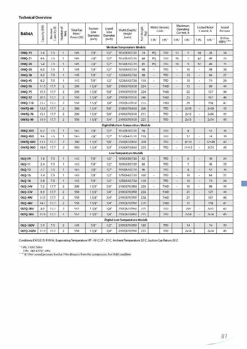
http://holodko.ru/
Technical Overview
R404A
Capa
city
(kW
)
Rece
iver
Capa
city
(l)
Num
ber
of
fans
Total Fan Motor
Power (W)
SuctionLine
Diameter(inch)
LiquidLine
Diameter(inch)
Width/Depth/Height(mm)
Net
Wei
ght
(kg)
Motor Version/ Code
Maximum Operating Current, A
Locked Rotor Current, A
SoundPressure
1 Ph* 3 Ph** 1 Ph* 3 Ph** 1 Ph* 3 Ph** @ 10 m - d(BA)***
Medium Temperature Models
OMQ-15 3.4 7.5 1 145 7/8" 1 /2 " 1050/630/720 74 PFJ TFD 13 5 58 26 34
OMQ-21 4.6 7.5 1 145 7/8" 1 /2 " 1050/630/720 84 PFJ TFD 16 7 82 40 35
OMQ-26 5.4 7.5 1 145 7/8" 1 /2 " 1050/630/720 85 PFJ TFD 18 9 97 46 35
OMQ-30 6.0 7.5 1 145 7/8" 1 /2 " 1050/630/720 98 - TFD - 10 - 49 36
OMQ-38 8.2 7.5 1 145 7/8" 1 /2 " 1250/642/720 99 - TFD - 13 - 66 37
OMQ-45 9.2 7.5 1 145 7/8" 1 /2 " 1250/642/720 118 - TFD - 13 - 74 39
OMQ-56 11.5 17.7 2 290 1 3/8" 5/8" 2100/670/950 224 - TWD - 15 - 99 44
OMQ-75 15.3 17.7 2 290 1 3/8" 5/8" 2100/670/950 224 - TWD - 22 - 127 44
OMQ-92 20.5 17.7 2 550 1 3/8" 3/4" 2100/670/950 246 - TWD - 25 - 167 46
OMQ-110 23.7 17.7 2 550 1 5/8" 3/4" 2100/670/950 255 - TWD - 29 - 198 47
OMTQ-60 13.0 17.7 2 290 1 3/8" 5/8" 2100/670/950 209 - TFD - 2x 10 - 2x49 42
OMTQ-76 15.1 17.7 2 290 1 3/8" 5/8" 2100/670/950 2 1 1 - TFD - 2x13 - 2 x66 43
OMTQ-90 19.9 17.7 2 550 1 3/8" 3/4" 2100/670/950 225 - TFD 2x13 - 2x74 45
Digital Medium Temperature Models
OMQ-30D 6 .2 7.5 1 145 7/8" 1 /2 " 1050/630/720 98 - TFD - 8 - 52 36
OMQ-45D 9.6 7.5 1 145 7/8" 1 /2 " 1250/642/720 118 - TFD - 1 2 - 74 39
OMTQ-60D 13.1 17.7 2 290 1 3/8" 5/8" 2100/670/950 209 - TFD - 8 + 10 - 52+49 42
OMTQ-90D 19.9 17.7 2 550 1 3/8" 3/4" 2100/670/950 225 - TFD - 11+13 - 2x74 45
Low Temperature Models
OLQ-09 1.9 7.5 1 145 7/8" 1 /2 " 1050/630/720 83 - TFD - 6 - 40 34
OLQ-11 2.4 7.5 1 145 7/8" 1 /2 " 1050/630/720 86 - TFD - 7 - 46 35
OLQ-13 2.7 7.5 1 145 7/8" 1 /2 " 1050/630/720 96 - TFD - 8 - 52 36
OLQ-15 3.4 7.5 1 145 7/8" 1 /2 " 1250/642/720 10 0 - TFD - 10 - 64 37
OLQ-18 5.9 7.5 1 145 7/8" 1 /2 " 1250/642/720 119 - TFD - 13 - 74 39
OLQ-24V 7.2 17.7 2 290 1 3/8" 5/8" 2100/670/950 228 - TWD - 16 - 99 44
OLQ-33V 9.9 17.7 2 550 1 3/8" 5/8" 2100/670/950 228 - TWD - 21 - 127 44
OLQ-40V 11.9 17.7 2 550 1 3/8" 3/4" 2100/670/950 238 - TWD - 27 - 167 46
OLQ-48V 14.7 17.7 2 550 1 5/8" 3/4" 2100/670/950 259 - TWD - 31 - 198 47
OLTQ-26V 8.0 17.7 2 551 1 3/8" 5/8" 2100/670/950 2 2 1 - TFD - 2x9 - 2x51 42
OLTQ-36V 11.9 17.7 2 552 1 3/8" 3/4" 2100/670/950 235 - TFD - 2x14 - 2x74 45
Digital Low Temperature Models
OLQ-18DV 5.9 7.5 2 145 7/8" 1 /2 " 2100/670/950 189 - TFD - 14 - 74 39
OLTQ-36DV 11.9 17.7 2 550 1 3/8" 3/4" 2100/670/950 235 - TFD - 2x14 - 2x74 45
Conditions EN13215: R404A, Evaporating Temperature MT -10°C/ LT - 35°C, Ambient Temperature 32°C, Suction Gas Return 20°C
* 1 Ph: 230V/ 50Hz ** 3 Ph: 380-420V/ 50Hz*** @ 1 0 m: sound pressure level at 1 0 m distance from the compressor, free field condition
81

http://holodko.ru/
Capacity Data
Cooling Capacity (kW) Power Input (kW)
R404AAmbient Temperature: 32°C
R404AAmbient Temperature: 32°C
Evaporating Temperature (°C) Evaporating Temperature (°C)
-45 -35 -30 -2 0 - 1 0 -5 5 -45 -35 -30 -2 0 -1 0 -5 5
Medium Temperature Models Medium Temperature Models
OMQ-15 1.4 2.3 3.4 3.9 5.2 OMQ-15 1 .8 1.9 2.0 2.0 2.1
OMQ-21 2 .0 * 3.3 4.6 5.3 6.7 OMQ-21 2.5 2.8 3.0 3.1 3.4
OMQ-26 2.3* 3.9 5.4 6.2 8.1 OMQ-26 2.9 3.2 3.4 3.5 3.8
0MQ-30 2 .0 * 2 .6 * 4.3 6.0 6.9 8.9 OMQ-30 3.3 3.4 3.8 4.1 4.3 4.7
OMQ-38 2.7* 3.5 5.8 8.2 9.5 12.4 OMQ-38 3.8 3.9 4.3 4.6 4.8 5.2
OMQ-45 3.1* 3.9* 6.6 9.2 10 .6 13.7 OMQ-45 4.5 4.6 5.1 5.5 5.7 6.2
OMQ-56 5.6* 8.3 11.5 13.4 17.4 OMQ-56 5.7 6.2 6.7 6.9 7.5
OMQ-75 11.3 15.3 17.4 2 2 .1 OMQ-75 8.2 9.3 9.8 10.9
OMQ-92 10 .2 14.9 20.5 23.7 30.7 OMQ-92 9.1 10 .2 1 1 . 2 1 1 .8 13.1
OMQ-110 17.3 23.7 27.3 35.1 OMQ-110 12.7 14.1 14.8 16.4
OMTQ-60 4.3* 5.5 9.4 13.1 15.1 19.6 OMTQ-60 6.2 6.4 7.0 7.5 7.8 8.4
OMTQ-76 5.1* 6.5 1 1 . 1 15.1 17.3 OMTQ-76 8.1 8.4 9.3 10 .1 10 .6
OMTQ-90 6.5* 9.5 14.2 19.9 23.1 30.2 OMTQ-90 8.7 9.1 9.7 10.3 10.7 11.5
Low Temperature Models Low Temperature Models
OLQ-09 1.9 2.3 3.3 4.5 5.2 6.6 OLQ-09 2.0 2.0 2.3 2.6 2.7 3.2
OLQ-11 2.4 2.8 3.9 5.2 5.9 7.5 OLQ-11 2.4 2.5 2.8 3.2 3.5 4.1
OLQ-13 2.7 3.3 4.7 6.3 7.1 9.0 OLQ-13 2.6 2.7 3.1 3.6 3.9 4.5
OLQ-15 3.4 4.2 6.1 8.3 9.5 12 .2 OLQ-15 3.0 3.2 3.6 4.2 4.5 5.3
OLQ-18 4.1 5.0 7.1 9.6 10.9 13.8 OLQ-18 3.7 3.9 4.4 5.0 5.3 6.1
OLQ-24V 7.2 8.8 12.3 16.4 18.6 23.3 OLQ-24V 5.6 6.0 6.9 7.9 8.6 10 .1
OLQ-33V 9.9 12 .0 16.9 22 .8 26.2 33.7 OLQ-33V 7.5 7.9 8.9 10 .0 10.7 12.3
OLQ-40V 11.9 15.0 21.5 28.5 32.1 39.3 OLQ-40V 8.7 9.9 12 .0 14.1 15.1 17.5
OLQ-48V 14.7 17.7 24.1 30.9 34.4 OLQ-48V 1 1 . 2 1 2 .2 14.8 18.2 20.3
OLTQ-26V 8.0 9.7 13.9 19.3 22.5 30.1 OLTQ-26V 6.3 6.6 7.3 8.1 8.5 9.4
Digital Medium Temperature Models Digital Medium Temperature Models
OMQ-30D 2 .8 * 4.6 6.2 7.0 8.8 OMQ-30D 2.5 3.2 3.7 3.9 4.5
OMQ-45D 3.6* 6.6 9.6 11.4 15.5 OMQ-45D 4.2 4.8 5.5 5.9 6.9
OMTQ-60D 5.7* 9.5 13.1 15.2 19.7 OMTQ-60D 5.6 6.5 7.2 7.5 8.3
OMTQ-90D 7.9* 13.9 20.0 23.5 31.5 OMTQ-90D 8.7 9.6 10.4 10.9 1 2 .1
Digital Low Temperature Models Digital Low Temperature Models
OLQ-18DV 5.9 6.9 9.5 12 .8 14.7 OLQ-18DV 4.5 4.9 5.8 7.0 7.7
OLTQ-36DV 11.9 14.1 19.5 26.4 30.6 OLTQ-36DV 8.8 9.4 10.9 12 .6 13.6
Conditions: EN13215: Suction Gas Return 20°C, Subcooling 0K* Conditions: EN13215: Suction Superheat 10K
82—
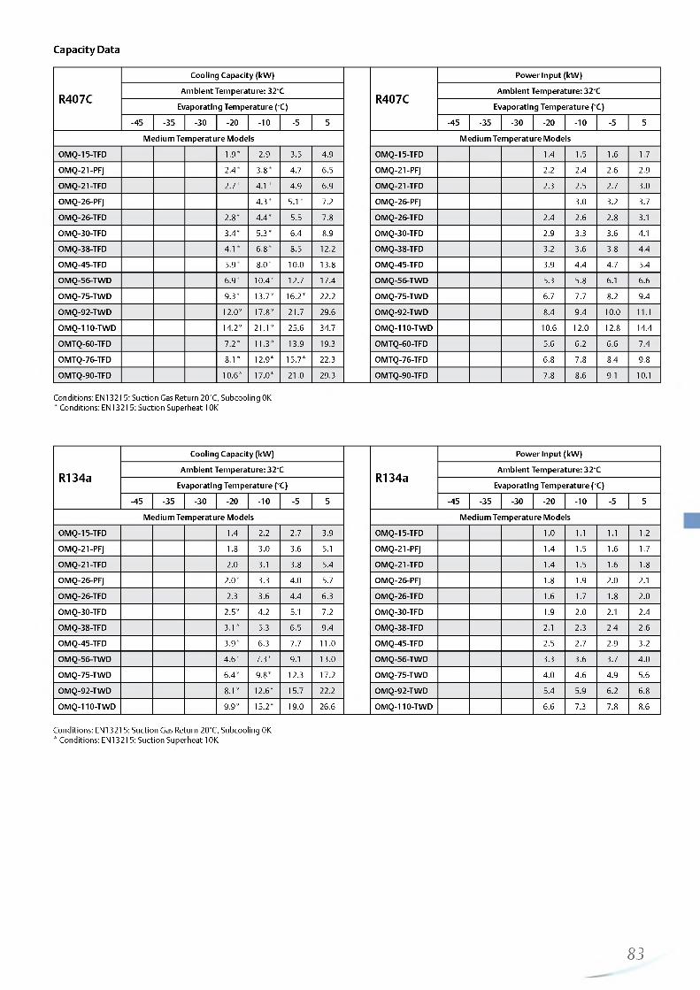
http://holodko.ru/
Capacity Data
R407C
Cooling Capacity (kW)
R407C
Power Input (kW)
Ambient Temperature: 32°C Ambient Temperature: 32°C
Evaporating Temperature (°C) Evaporating Temperature (°C)
-45 -35 -30 -2 0 - 1 0 -5 5 -45 -35 -30 -2 0 - 1 0 -5 5
Medium Temperature Models Medium Temperature Models
OMQ-15-TFD 1.9* 2.9 3.5 4.9 OMQ-15-TFD 1.4 1.5 1 .6 1.7
OMQ-21-PFJ 2.4* 3.8* 4.7 6.5 OMQ-21-PFJ 2.2 2.4 2.6 2.9
OMQ-21-TFD 2.7* 4.1* 4.9 6.9 OMQ-21-TFD 2.3 2.5 2.7 3.0
OMQ-26-PFJ 4.3* 5.1* 7.2 OMQ-26-PFJ 3.0 3.2 3.7
OMQ-26-TFD 2 .8 * 4.4* 5.5 7.8 OMQ-26-TFD 2.4 2.6 2.8 3.1
OMQ-30-TFD 3.4* 5.3* 6.4 8.9 OMQ-30-TFD 2.9 3.3 3.6 4.1
OMQ-38-TFD 4.1* 6 .8 * 8.5 12 .2 OMQ-38-TFD 3.2 3.6 3.8 4.4
OMQ-45-TFD 5.9* 8 .0 * 10 .0 13.8 OMQ-45-TFD 3.9 4.4 4.7 5.4
OMQ-56-TWD 6.9* 10.4* 12.7 17.4 OMQ-56-TWD 5.3 5.8 6.1 6.6
OMQ-75-TWD 9.3* 13.7* 16.2* 2 2 .2 OMQ-75-TWD 6.7 7.7 8.2 9.4
OMQ-92-TWD 1 2 .0 * 17.8* 21.7 29.6 OMQ-92-TWD 8.4 9.4 10 .0 1 1 . 1
OMQ-110-TWD 14.2* 2 1 . 1 * 25.6 34.7 OMQ-110-TWD 10 .6 1 2 .0 12 .8 14.4
OMTQ-60-TFD 7.2* 11.3* 13.9 19.3 OMTQ-60-TFD 5.6 6 .2 6.6 7.4
OMTQ-76-TFD 8 . 1 * 12.9* 15.7* 22.3 OMTQ-76-TFD 6.8 7.8 8.4 9.8
OMTQ-90-TFD 1 0 .6 * 17.0* 2 1 .0 29.3 OMTQ-90-TFD 7.8 8.6 9.1 10 .1
Conditions: EN13215: Suction Gas Return 20°C, Subcooling 0K* Conditions: EN13215: Suction Superheat 10K
R134a
Cooling Capacity (kW)
R134a
Power Input (kW)
Ambient Temperature: 32°C Ambient Temperature: 32°C
Evaporating Temperature (°C) Evaporating Temperature (°C)
-45 -35 -30 -2 0 - 1 0 -5 5 -45 -35 -30 -2 0 -1 0 -5 5
Medium Temperature Models Medium Temperature Models
OMQ-15-TFD 1.4 2.2 2.7 3.9 OMQ-15-TFD 1 .0 1 .1 1 .1 1 .2
OMQ-21-PFJ 1.8 3.0 3.6 5.1 OMQ-21-PFJ 1.4 1.5 1 .6 1.7
OMQ-21-TFD 2.0 3.1 3.8 5.4 OMQ-21-TFD 1.4 1.5 1 .6 1.8
OMQ-26-PFJ 2 .0 * 3.3 4.0 5.7 OMQ-26-PFJ 1.8 1.9 2.0 2.1
OMQ-26-TFD 2.3 3.6 4.4 6.3 OMQ-26-TFD 1 .6 1.7 1 .8 2.0
OMQ-30-TFD 2.5* 4.2 5.1 7.2 OMQ-30-TFD 1.9 2.0 2.1 2.4
OMQ-38-TFD 3.1* 5.3 6.5 9.4 OMQ-38-TFD 2.1 2.3 2.4 2.6
OMQ-45-TFD 3.9* 6.3 7.7 1 1 .0 OMQ-45-TFD 2.5 2.7 2.9 3.2
OMQ-56-TWD 4.6* 7.3* 9.1 13.0 OMQ-56-TWD 3.3 3.6 3.7 4.0
OMQ-75-TWD 6.4* 9.8* 12.3 17.2 OMQ-75-TWD 4.0 4.6 4.9 5.6
OMQ-92-TWD 8 . 1 * 1 2 .6 * 15.7 2 2 .2 OMQ-92-TWD 5.4 5.9 6.2 6.8
OMQ-110-TWD 9.9* 15.2* 19.0 26.6 OMQ-110-TWD 6.6 7.3 7.8 8.6
Conditions: EN13215: Suction Gas Return 20°C, Subcooling 0K* Conditions: EN13215: Suction Superheat 10K
83

http://holodko.ru/
Capacity Data
R407ACooling Capacity (kW)
R407APower Input (kW)
Ambient Temperature: 32°C Ambient Temperature: 32°C
Evaporating Temperature (°C) Evaporating Temperature (°C)
Model -45 -35 -30 -2 0 -1 0 -5 5 Model -45 -35 -30 -2 0 - 1 0 -5 5
OMQ-15-TFD 2.1 3.3 3.9 5.4 OMQ-15-TFD 1.7 1 .8 1.9 2.1
OMQ-21-TFD 2.9 4.4 5.2 7.0 OMQ-21-TFD 2.5 2.8 3.0 3.2
OMQ-26-TFD 3.3 5.2 6.1 8.4 OMQ-26-TFD 2.7 3.0 3.2 3.6
OMQ-30-TFD 3.9 6.1 7.2 9.5 OMQ-30-TFD 3.3 3.7 4.0 4.6
OMQ-38-TFD 5.2 8.1 9.7 13.2 OMQ-38-TFD 3.6 4.0 4.2 4.8
OMQ-45-TFD 5.9 9.0 10 .6 14.2 OMQ-45-TFD 4.4 5.0 5.3 5.9
OMTQ-60-TFD 6.3* 1 1 .1 * 14.0 20.4 OMTQ-60-TFD 5.7* 6 .2 * 6.5 7.3
OMTQ-76-TFD 9.4* 14.3* 17.3* 24.0 OMTQ-76-TFD 6.9* 7.8* 8.3* 9.6
OMTQ-90-TFD 12.9* 19.3* 23.1 31.5 OMTQ-90-TFD 8 .6 * 9.2* 9.5 10.4
Conditions: EN13215: Suction Gas Return 20°C, Subcooling 0K* Suction Superheat 10K
84

http://holodko.ru/

http://holodko.ru/
Copeland EazyCool™ Outdoor Condensing Units for Refrigeration Networks
Copeland™ outdoor condensing unit networks for medium temperature and low temperature applications.
Emerson Climate Technologies has developed this version of outdoor scroll condensing units with interconnectivity in order to create medium and large size refrigeration network systems.
The EazyCool condensing unit networks perfectly fit in applications where larger cooling capacities and capacity modulation are required.
Typical applications are:- Cold and freeze stores- Discount and convenience stores- Supermarkets and mini-markets- Petrol station forecourts
Copeland EazyCool Outdoor Condensing Units for Refrigeration Networks
Copeland EazyCool Network Line-up
Medium Temperature • • • M • M M t • • « M • M • • • • • • • •
Low Temperature • • • • • M M N t a N H * * * • • • •
Capacity (kW )10 20 30 40 50 60 70 80 90 100
Conditions EN13215 R404A: Evaporating Temperature MT -10°C/LT -35°C, Ambient Temperature 32°C, Suction Gas Return 20°C
Features and Benefits Maximum Allowable Pressures (PS)
Standard equipment: Copeland Scroll™ compressor(s), crankcase heater(s), condenser with thermally protected low speed fan(s), fan speed controller, oil separator, suction and liquid equalization lines, HP and LP switch, oil reservoir, EC2 Electronic controller, weather resistant housing Oil control system with oil separator, TRAX OIL on each compressor, oil distribution lines and additional liquid receiver unit for large networks LON Master/Slave communicationCapacity modulation with up to 8 compressors or stepless with Digital Scroll™Perfect capacity adjustment by a wide range of combination opportunities
Low Side PS 22.5 bar(g) High Side PS 28 bar(g)
86
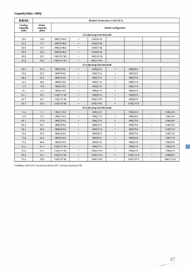
http://holodko.ru/
Capacity Data - OMQ
R404A Medium Temperature (-10/+32°C)
CoolingCapacitiy
(kW)
Motor Capacity
(kW )Model Configuration
2 Condensing Units Network
28.0 14.8 OMQ75 NLO + OMQ56 NL
32.2 17.1 OMQ75 NLO + OMQ75 NL
36.0 19.7 OMQ92 NLO + OMQ75 NL
39.8 2 2 .2 OMQ92 NLO + OMQ92 NL
42.8 25.1 0MQ110 NLO + OMQ 92 NL
45.8 28.0 0MQ110 NLO + 0MQ110 NL
3 Condensing Units Network
39.8 2 1 .0 OMQ75 NO + 0MQ56 N + 0MQ56 N
44.0 23.3 OMQ75 NO + 0MQ75 N + 0MQ56 N
48.3 25.7 OMQ75 NO + 0MQ75 N + 0MQ75 N
52.1 28.2 OMQ92 NO + 0MQ75 N + 0MQ75 N
55.9 30.8 OMQ92 NO + 0MQ92 N + 0MQ75 N
59.7 33.3 OMQ92 NO + 0MQ92 N + 0MQ92 N
62.7 36.2 OMQ110 NO + 0MQ92 N + 0MQ92 N
65.7 39.1 OMQ110 NO + 0MQ110 N + 0MQ92 N
68.7 42.0 OMQ110 NO + 0MQ110 N + 0MQ110 N
4 Condensing Units Network
51.6 27.2 OMQ75 NO + 0MQ56 N + 0MQ56 N + 0MQ56 N
55.9 29.5 OMQ75 NO + 0MQ75 N + 0MQ56 N + 0MQ56 N
60.1 31.9 OMQ75 NO + 0MQ75 N + 0MQ75 N + 0MQ56 N
64.4 34.2 OMQ75 NO + 0MQ75 N + 0MQ75 N + 0MQ75 N
68.2 36.8 OMQ92 NO + 0MQ75 N + 0MQ75 N + 0MQ75 N
72.0 39.3 OMQ92 NO + 0MQ92 N + 0MQ75 N + 0MQ75 N
75.8 41.9 OMQ92 NO + 0MQ92 N + 0MQ92 N + 0MQ75 N
79.6 44.4 OMQ92 NO + 0MQ92 N + 0MQ92 N + 0MQ92 N
82.6 47.3 OMQ110 NO + 0MQ92 N + 0MQ92 N + 0MQ92 N
85.6 50.2 OMQ110 NO + 0MQ110 N + 0MQ92 N + 0MQ92 N
88.6 53.1 OMQ110 NO + 0MQ110 N + 0MQ110 N + 0MQ92 N
91.6 56.0 OMQ110 no + 0MQ110 N + 0MQ110 N + 0MQ110 N
Conditions: EN13215: Suction Gas Return 20°C, Suction Superheat 10K
87
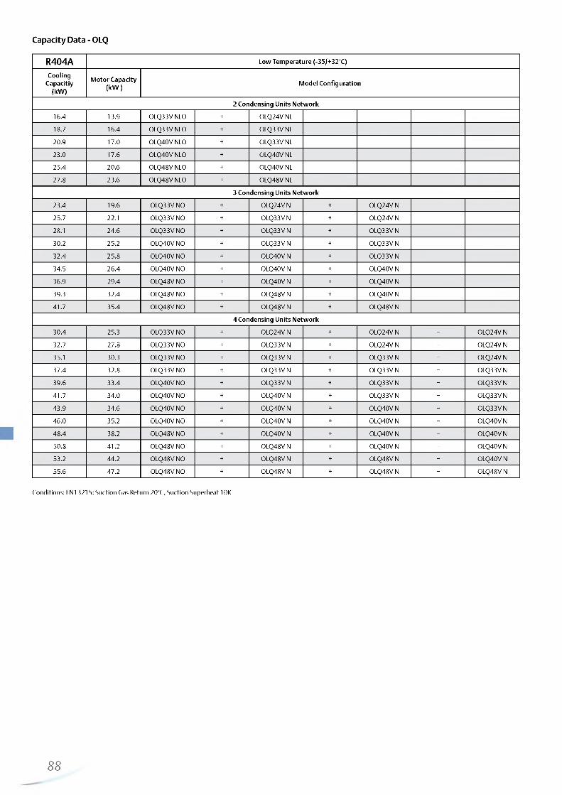
http://holodko.ru/
Capacity Data - OLQ
R404A Low Temperature (-35/+32°C)
CoolingCapacitiy
(kW)Motor Capacity
(kW ) Model Configuration
2 Condensing Units Network
16.4 13.9 OLQ33V NLO + OLQ24V NL
18.7 16.4 OLQ33V NLO + OLQ33V NL
20.9 17.0 0LQ40V NLO + OLQ33V NL
23.0 17.6 0LQ40V NLO + OLQ40V NL
25.4 20.6 OLQ48V NLO + OLQ40V NL
27.8 23.6 OLQ48V NLO + OLQ48V NL
3 Condensing Units Network
23.4 19.6 OLQ33V NO + OLQ24V N + OLQ24V N
25.7 2 2 .1 OLQ33V NO + OLQ33V N + OLQ24V N
28.1 24.6 OLQ33V NO + OLQ33V N + OLQ33V N
30.2 25.2 OLQ40V NO + OLQ33V N + OLQ33V N
32.4 25.8 OLQ40V NO + OLQ40V N + OLQ33V N
34.5 26.4 OLQ40V NO + OLQ40V N + OLQ40V N
36.9 29.4 OLQ48V NO + OLQ40V N + OLQ40V N
39.3 32.4 OLQ48V NO + OLQ48V N + OLQ40V N
41.7 35.4 OLQ48V NO + OLQ48V N + OLQ48V N
4 Condensing Units Network
30.4 25.3 OLQ33V NO + OLQ24V N + OLQ24V N + OLQ24V N
32.7 27.8 OLQ33V NO + OLQ33V N + OLQ24V N + OLQ24V N
35.1 30.3 OLQ33V NO + OLQ33V N + OLQ33V N + OLQ24V N
37.4 32.8 OLQ33V NO + OLQ33V N + OLQ33V N + OLQ33V N
39.6 33.4 OLQ40V NO + OLQ33V N + OLQ33V N + OLQ33V N
41.7 34.0 OLQ40V NO + OLQ40V N + OLQ33V N + OLQ33V N
43.9 34.6 OLQ40V NO + OLQ40V N + OLQ40V N + OLQ33V N
46.0 35.2 OLQ40V NO + OLQ40V N + OLQ40V N + OLQ40V N
48.4 38.2 OLQ48V NO + OLQ40V N + OLQ40V N + OLQ40V N
50.8 41.2 OLQ48V NO + OLQ48V N + OLQ40V N + OLQ40V N
53.2 44.2 OLQ48V NO + OLQ48V N + OLQ48V N + OLQ40V N
55.6 47.2 OLQ48V NO + OLQ48V N + OLQ48V N + OLQ48V N
Conditions: EN13215: Suction Gas Return 20°C, Suction Superheat 10K
88

http://holodko.ru/

http://holodko.ru/
Copeland™ compact outdoor condensing units are for medium temperature and low temperature applications.
With this new range of outdoor condensing units, Emerson Climate Technologies offers a solution for refrigeration applications with space and noise constraints which responds to the increasing demand for energy-efficient condensing units.
Copeland EazyCool ZX outdoor condensing units feature the most complete and unique equipment. Their diagnostics module detects and displays the system status and it can communicate and transmit an alarm signal to a remote receiver. Vapor injection and liquid injection technology significantly increase system efficiency and operation map. Electronic protection functions, oil separator and suction accumulator guarantee optimum system safety.
Lowest life cycle costs and comprehensive safety features make Copeland EazyCool ZX a cost efficient and reliable choice for:- Convenience stores- Cold rooms- Fast food stores, bars and restaurants- Beverage coolers
Copeland EazyCool ZX Line-up
Copeland EazyCool™ ZX Outdoor Condi sing Units with Scroll Compressors
Copeland EazyCool ZX Outdoor Condensing Units with Scroll Compressors
Medium Temperature • • • • • •
Low Temperature • • • • •
Capacity (kW ) 1 10 2 4 6 8 10 1 2
Conditions EN13215 R404A: Evaporating Temperature MT -10°C/LT -35°C, Ambient Temperature 32°C, Suction Gas Return 20°C
Copeland EazyCool ZX Digital Line-up
Medium Temperature
Capacity (kW )1 0 1 268
Conditions EN13215 R404A: Evaporating Temperature MT -10°C/LT -35°C, Ambient Temperature 32°C, Suction Gas Return 20°C
Features and Benefits Maximum Allowable Pressures (PS)
• Standard equipment: Copeland Scroll™ compressor, • Low Side PS 22.5 bar (g)crankcase heater, diagnostics module, fan(s) with speed • High Side PS 28.8 bar (g)control, liquid receiver, adjustable LP switch, safety switches,filter drier and sight glass, oil separator and suction accumulator (LT models only)
• Copeland EazyCool ZX Digital models allow for 10% to 100% continuous capacity modulation
• Diagnostic capabilities protect the unit from over-current, phase loss and phase imbalance
• LED display shows real time system status• Energy and operation cost saving due to excellent energy
efficiency• Noise attenuation due to low speed fan motors with sickle
blades, fan speed control and sound jacket• Vapor injection technology for LT models• Space saving due to compact dimensions• Easy and quick installation
90

http://holodko.ru/
Technical Overview
R404ACa
pacit
y(k
W)
Rece
iver
Capa
city
(l)
Num
ber
of fa
ns
Tota
l Fan
Mot
or P
ower
(W
)
Sucti
on
Line
Diam
eter
(in
ch)
Liquid
Lin
e Di
amet
er (
inch
)
Width/Depth/Heigth(mm)
■Mhgi
£ ^t ( ez
Motor Version/ Code
Maximum Operating Current, A
Locked Rotor Current, A
Sound Pressure @ 10 m -
d(BA)***
1 Ph* 3 Ph** 1 Ph* 3 Ph** 1 Ph* 3 Ph** Nightmode
Daymode
Medium Temperature Models
ZXME020E 3.6 4.4 1 116 3/4” 1 /2 ” 1029/424/840 76 PFJ TFD 13 5 58 26 36 39
ZXME025E 4.3 4.4 1 116 3/4” 1 /2 ” 1029/424/840 79 PFJ 1 2 61 37 40
ZXME030E 5.3 4.4 1 116 3/4” 1 /2 ” 1029/424/840 79 PFJ TFD 16 6 82 40 37 40
ZXME040E 7.0 4.4 1 116 7/8” 1 /2 ” 1029/424/840 91 PFJ TFD 24 9 114 49 37 40
ZXME050E 9.1 6.3 2 246 7/8” 1 /2 ” 1029/424/1242 108 TFD 13 66 38 41
ZXME060E 10.4 6.3 2 246 7/8” 1 /2 ” 1029/424/1242 1 1 2 TFD 12 74 38 41
ZXME075E 11.9 6.3 2 246 7/8” 1 /2 ” 1029/424/1242 118 TFD 15 10 1 39 42
Medium Temperature Digital Models
ZXDE040E 7.0 6.3 2 246 7/8” 1 /2 ” 1029/424/1242 104 TFD 1 1 64 37 40
ZXDE050E 9.1 6.3 2 246 7/8” 1 /2 ” 1029/424/1242 108 TFD 1 2 66 38 41
ZXDE060E 10.4 6.3 2 246 7/8” 1 /2 ” 1029/424/1242 1 1 2 TFD 1 1 74 38 41
ZXDE075E 11.9 6.3 2 246 7/8” 1 /2 ” 1029/424/1242 118 TFD 10 46 39 42
Low Temperature Models
ZXLE020E 1.9 4.4 1 116 3/4” 1 /2 ” 1029/424/840 79 TFD 6 36 36 39
ZXLE030E 2.6 4.4 1 116 3/4” 1 /2 ” 1029/424/840 81 TFD 7 39 37 40
ZXLE040E 4.0 4.4 1 116 7/8” 1 /2 ” 1029/424/840 93 TFD 9 52 37 40
ZXLE050E 4.7 6.3 2 246 7/8” 1 /2 ” 1029/424/1242 106 TFD 1 2 52 38 41
ZXLE060E 5.7 6.3 2 246 7/8” 1 /2 ” 1029/424/1242 116 TFD 14 74 38 41
Conditions EN13215: R404A, Evaporating Temperature MT -10°C/ LT - 35°C, Ambient Temperature 32°C, Suction Gas Return 20°C
* 1 Ph: 230V/ 50Hz ** 3 Ph: 380-420V/ 50Hz*** @ 1 0 m: sound pressure level at 1 0 m distance from the compressor, free field condition
Capacity Data
R404A
Cooling Capacity (kW)
R404A
Power Input (kW)
Ambient Temperature: 32°C Ambient Temperature: 32°C
Evaporating Temperature (°C) Evaporating Temperature (°C)
-45 -35 -30 -2 0 - 1 0 -5 5 -45 -35 -30 -2 0 -1 0 -5 5
Medium Temperature Models Medium Temperature Models
ZXME020E-TFD 2.4 3.6 4.2 5.7 ZXME020E-TFD 1.8 1.8 1.8 1.8
ZXME020E-PFJ 2.5 3.6 4.3 5.7 ZXME020E-PFJ 1.5 1.6 1.7 1.7
ZXME025E-PFJ 3.0 4.3 5.1 6.9 ZXME025E-PFJ 1.9 2.0 2.0 2.1
ZXME030E-TFD 3.7 5.3 6.2 8.2 ZXME030E-TFD 2.4 2.5 2.6 2.7
ZXME030E-PFJ 3.8 5.3 6.2 8.3 ZXME030E-PFJ 2.5 2.6 2.7 2.8
ZXME040E-TFD 5.0 7.0 8.2 10 .8 ZXME040E-TFD 3.2 3.4 3.5 3.8
ZXME040E-PFJ 4.7 6.8 8.0 10 .6 ZXME040E-PFJ 3.2 3.4 3.5 3.8
ZXDE040E-TFD 5.0 7.0 8.1 10.7 ZXDE040E-TFD 2.8 3.2 3.3 3.7
ZXME050E-TFD 6.4 9.1 10.7 14.4 ZXME050E-TFD 4.0 4.1 4.3 4.5
ZXDE050E-TFD 6.4 9.0 10 .6 14.1 ZXDE050E-TFD 3.6 4.0 4.2 4.7
ZXME060E-TFD 7.3 10.4 1 2 .2 16.2 ZXME060E-TFD 4.6 4.8 5.0 5.3
ZXDE060E-TFD 7.4 10.4 1 2 .2 16.1 ZXDE060E-TFD 4.3 4.9 5.2 5.8
ZXME075E-TFD 8.4 11.9 13.9 18.5 ZXME075E-TFD 5.1 5.4 5.5 5.9
ZXDE075E-TFD 8.4 1 1 .8 13.8 18.2 ZXDE075E-TFD 4.7 5.3 5.6 6.3
Low Temperature Models Low Temperature Models
ZXLE020E-TFD 1.9 2.4 3.5 4.9 5.7 ZXLE020E-TFD 1.7 1 .8 1.9 2.1 2 .2
ZXLE030E-TFD 2.6 3.1 4.6 6.4 7.4 ZXLE030E-TFD 2.0 2 .2 2.3 2.6 2.7
ZXLE040E-TFD 4.0 4.9 7.0 9.6 1 1 .0 ZXLE040E-TFD 3.0 3.2 3.7 4.2 4.4
ZXLE050E-TFD 4.7 5.6 7.9 10.7 1 2 .2 ZXLE050E-TFD 3.6 3.8 4.2 4.7 5.0
ZXLE060E-TFD 5.7 7.0 10 .0 13.4 15.2 ZXLE060E-TFD 4.4 4.7 5.4 6.3 6.7
Conditions: EN13215: Suction Gas Return 20°C, Subcooling 0K
91

http://holodko.ru/
Capacity Data
R407ACooling Capacity (kW )
R407APow er Input (kW )
A m bient Tem perature: 32°C Am bient Tem perature: 32°C
Evaporating Tem perature (°C) Evaporating Tem perature (°C)
Model -45 -35 -30 - 2 0 - 1 0 -5 5 Model -45 -35 -30 - 2 0 - 1 0 -5 5
ZXME020E-TFD 2.4 3.5 4.1 5.6 ZXM E020E-TFD 1 .6 1.7 1.7 1.7
ZXME030E-TFD 3.2 4.9 5.9 8.3 ZXM E030E-TFD 2 .1 2.3 2.3 2 .6
ZXME040E-TFD 4.5 6.9 8.3 11.5 ZXM E040E-TFD 3.0 3.2 3.3 3.7
ZXME050E-TFD 5.8 8.7 10.4 14.4 ZXM E050E-TFD 3.5 3.7 3.9 4.3
ZXME060E-TFD 6.4 9.8 1 1 . 8 16.4 ZXME060E-TFD 4.0 4.3 4.5 5.0
ZXME075E-TFD 7.4 11.3 13.6 18.9 ZXM E075E-TFD 4.5 4.9 5.1 6 .0
Conditions: EN13215: Suction Gas Return 20°C, Subcooling 0K
R407FCooling Capacity (kW )
R407FPow er Input (kW )
A m bient Tem perature: 32°C Am bient Tem perature: 32°C
Evaporating Tem perature (°C) Evaporating Tem perature (°C)
Model -45 -35 -30 - 2 0 - 1 0 -5 5 Model -45 -35 -30 - 2 0 - 1 0 -5 5
ZXME020E-TFD 3.2 3.9 5.6 ZXME020E-TFD 1.7 1.7 1 .8
ZXME030E-TFD 4.8 5.8 8.1 ZXM E030E-TFD 2.4 2.5 2.7
ZXME040E-TFD 6.7 8.2 11.4 ZXM E040E-TFD 3.3 3.5 3.8
ZXME050E-TFD 8.7 10.5 14.9 ZXM E050E-TFD 4.1 4.2 4.5
ZXME060E-TFD 10 .0 12 .1 17.0 ZXM E060E-TFD 4.8 5.0 5.5
ZXME075E-TFD 11.7 14.6 20.4 ZXM E075E-TFD 5.7 5.9 6.1
Conditions: EN13215: Suction Gas Return 20°C, Subcooling 0K Preliminary data
92—

http://holodko.ru/

http://holodko.ru/
Copeland Scroll™ Indoor Condensing Units for RefrigerationCopeland™ air-cooled condensing units for medium temperature and low temperature applications.
Copeland Scroll condensing units are equipped with the latest refrigeration scroll compressors and build the widest range of its kind. The modular line concept offers base units which can be adapted to the target application by various options including weather housings and fan speed controls.
Copeland Scroll condensing units are available with normal or high capacity condensers to ensure optimum performance even under extreme conditions. They are equipped with dedicated medium or low temperature compressors which makes them suitable for all general refrigeration applications, such as:
Mini markets and supermarkets Bars, restaurants and kitchens Beer cellars and beverage coolers Cold rooms Milk cooling tank Copeland Scroll
Indoor Condensing Unit
Copeland Scroll Condensing Units Line-up
Medium Temperature • • • • • • • • • • • • • • • • • • • • •
Low Temperature • • • • • • • • • • • • • • •
Capacity (kW )0 5 10 15 20 25
Conditions EN13215 R404A: Evaporating Temperature MT -10°C/LT -35°C, Ambient Temperature 32°C, Suction Gas Return 20°C
Copeland Scroll Digital Condensing Units Line-up
Medium Temperature • • • • 1
Capacity (kW )5 7 9 11 13 15 17 19 21
Conditions EN13215 R404A: Evaporating Temperature -10°C, Ambient Temperature 32°C, Suction Gas Return 20°C
Features and Benefits
• Standard equipment: base plate, scroll compressor, crank case heater, condenser with 1ph fan(s), HP and LP switch, liquid receiver with rotalock-valve, suction- and discharge shut-off valves
• Suitable for multiple refrigerants: R404A, R407C, R143a, R407A and R407F
• Wide range of quality accessories• Excellent efficiency and reliability
Maximum Allowable Pressures (PS)
• Low Side PS 22.5 bar (g)• High Side PS = 28 bar (g)
94

http://holodko.ru/
Technical Overview
R404A
Capa
city
(kW
)
Rece
iver
Capa
city
(l)
Num
ber
of fa
ns
Tota
l Fan
Mot
or P
ower
(W
)
Sucti
on
Line
Diam
eter
(in
ch)
Liquid
Lin
e Di
amet
er (
inch
)
Width/Depth/Heigth(mm)
Net
Weig
ht (
kg) Motor Version/
Code
Maximum Operating Current, A
Locked Rotor Current, A
SoundPressure
1 Ph* 3 Ph** 1 Ph* 3 Ph** 1 Ph* 3 Ph** @ 10 m - d(BA)***
Medium Temperature Models
MC-D8-ZB15KE 3.3 3.9 1 1 1 0 3/4” 1 /2 ” 560/570/446 48 PFJ TFD 13 5 58 26 46
MC-H8-ZB15KE 3.6 7.9 1 235 3/4” 1 /2 ” 735/680/533 57 PFJ TFD 13 5 58 26 49
MC-D8-ZB19KE 3.9 3.9 1 1 1 0 3/4” 1 /2 ” 560/570/446 49 PFJ TFD 13 7 61 32 46
MC-H8-ZB19KE 4.3 7.9 1 235 3/4” 1 /2 ” 735/680/533 61 PFJ TFD 13 7 61 32 49
MC-K9-ZB19KE 4.3 7.9 2 2 0 3/4” 1 /2 ” 950/640/454 67 PFJ TFD 13 7 61 32 48
MC-D8-ZB21KE 4.4 3.9 1 1 1 0 7/8” 1 /2 ” 560/570/446 50 PFJ TFD 16 7 82 40 46
MC-H8-ZB21KE 5.1 7.9 1 235 7/8” 1 /2 ” 735/680/533 61 PFJ TFD 16 7 82 40 49
MC-K9-ZB21KE 5.1 7.9 2 2 0 7/8” 1 /2 ” 950/640/454 68 PFJ TFD 16 7 82 40 48
MC-H8-ZB26KE 5.6 7.9 1 235 7/8” 1 /2 ” 735/680/533 62 PFJ TFD 18 9 97 46 49
MC-K9-ZB26KE 5.6 7.9 2 2 0 7/8” 1 /2 ” 950/640/454 68 PFJ TFD 18 9 97 46 48
MC-H8-ZB30KE 6.4 7.9 1 235 7/8” 1 /2 ” 735/680/533 74 PFJ TFD 26 10 142 49 49
MC-M8-ZB30KE 6.8 7.9 1 235 7/8” 1 /2 ” 735/730/708 87 PFJ TFD 26 10 142 49 49
MC-P8-ZB30KE 7.1 7.9 2 2 0 7/8” 1 /2 ” 950/640/633 87 TFD 10 49 49
MC-H8-ZB38KE 7.3 7.9 1 235 7/8” 1 /2 ” 735/680/533 77 PFJ TFD 32 13 142 66 49
MC-M8-ZB38KE 8.0 7.9 1 235 7/8” 1 /2 ” 735/730/708 89 PFJ TFD 32 13 142 66 49
MC-P8-ZB38KE 8.4 7.9 2 2 0 7/8” 1 /2 ” 950/640/633 89 PFJ TFD 32 13 142 66 49
MC-M8-ZB42KE 8.7 7.9 1 235 7/8” 1 /2 ” 735/730/708 91 PFJ 36 150 49
MC-M8-ZB45KE 8.9 7.9 1 235 7/8” 1 /2 ” 735/730/708 91 TFD 13 74 49
MC-M9-ZB45KE 9.6 7.9 1 400 7/8” 1 /2 ” 735/730/708 96 TFD 13 74 49
MC-R7-ZB42KE 9.8 7.9 2 470 7/8” 1 /2 ” 1130/680/633 10 1 PFJ 36 150 53
MC-R7-ZB45KE 10 .1 7.9 2 470 7/8” 1 /2 ” 1130/680/633 10 1 TFD 13 74 50
MC-R7-ZB50KE 11.4 7.9 2 470 1 3/8” 1 /2 ” 1130/820/621 1 1 0 TFD 15 10 0 49
MC-S9-ZB50KE 12 .0 11.7 2 470 1 3/8” 5/8” 1130/820/707 113 TFD 15 10 0 49
MC-R7-ZB58KE 12.4 7.9 2 470 7/8” 1 /2 ” 1130/680/633 1 1 0 TFD 15 95 49
MC-S9-ZB58KE 13.1 11.7 2 470 7/8” 1 /2 ” 1130/820/703 113 TFD 15 95 50
MC-S9-ZB66KE 14.5 11.7 2 470 1 3/8” 5/8” 1130/820/707 116 TFD 18 1 1 1 50
MC-V9-ZB66KE 15.1 15.8 2 470 1 3/8” 3/4” 1330/820/821 150 TFD 18 1 1 1 50
MC-V9-ZB76KE 17.2 15.8 2 470 1 3/8” 3/4” 1330/820/835 151 TFD 20 118 50
MC-V6-ZB76KE 18.5 15.8 2 800 1 3/8” 3/4” 1330/820/835 168 TFD 20 118 55
MC-V9-ZB95KE 19.3 15.8 2 470 1 3/8” 3/4” 1330/820/835 155 TFD 28 140 51
MC-V6-ZB95KE 21.5 15.8 2 800 1 3/8” 3/4” 1330/820/835 172 TFD 28 140 55
MC-V6-ZB114KE 24.3 15.8 2 800 1 3/8” 3/4” 1330/820/835 174 TFD 33 174 55
MC-W9-ZB114KE 24.6 15.8 2 800 1 3/8” 3/4” 1640/820/864 174 TFD 33 174 55
Digital Medium Temperature Models
MC-M8-ZBD30 6.9 11.7 1 235 7/8” 5/8” 735/730/708 87 TFD 8 52 49
MC-M9-ZBD45 9.9 11.7 1 400 7/8” 5/8” 735/730/708 96 TFD 1 2 74 49
MC-V6-ZBDT60 14.9 18.9 2 800 1 3/8” 3/4” 1330/820/835 207 TFD 8 + 10 52+49 55
MC-V6-ZBDT90 20.4 18.9 2 800 1 3/8” 3/4” 1330/820/835 218 TFD 11+13 2x74 55
Conditions EN13215: R404A, Evaporating Temperature MT -10°C/ LT - 35°C, Ambient Temperature 32°C, Suction Gas Return 20°C
* 1 Ph: 230V/ 50Hz ** 3 Ph: 380-420V/ 50Hz*** @ 1 0 m: sound pressure level at 1 0 m distance from the compressor, free field condition
95

http://holodko.ru/
Technical Overview
R404ACa
pacit
y(k
W)
Rece
iver
Capa
city
(l)
Num
ber
of fa
ns
Tota
l Fan
Mot
or P
ower
(W
)
Sucti
on
Line
Diam
eter
(in
ch)
Liquid
Lin
e Di
amet
er (
inch
)
Width/Depth/Heigth(mm)
Net
Weig
ht (
kg) Motor Version/
CodeMaximum Operating Current, A
Locked Rotor Current, A
SoundPressure
1 Ph* 3 Ph** 1 Ph* 3 Ph** 1 Ph* 3 Ph** @ 10 m - d(BA)***
Low Temperature Models
MC-B8-ZF06KE 1.3 3.3 1 85 7/8” 1 /2 ” 560/570/396 64 TFD 5 26 47
MC-D8-ZF09KE 1.9 3.9 1 1 1 0 7/8” 1 /2 ” 560/570/446 64 TFD 6 40 47
MC-H8-ZF09KE 2.0 7.9 1 235 7/8” 1 /2 ” 735/680/533 66 TFD 6 40 49
MC-H8-ZF11KE 2.5 7.9 1 235 7/8” 1 /2 ” 735/680/533 67 TFD 7 46 49
MC-H8-ZF13KE 2.8 7.9 1 235 7/8” 1 /2 ” 735/680/533 77 TFD 8 52 50
MC-M8-ZF13KE 2.8 7.9 1 235 7/8” 1 /2 ” 735/730/708 85 TFD 8 52 49
MC-H8-ZF15KE 3.3 7.9 1 235 7/8” 1 /2 ” 735/680/533 83 TFD 10 64 50
MC-M8-ZF15KE 3.4 7.9 1 235 7/8” 1 /2 ” 735/730/708 86 TFD 10 64 50
MC-M8-ZF18KE 4.1 7.9 1 235 7/8” 1 /2 ” 735/730/708 88 TFD 13 74 50
MC-M9-ZF18KE 4.2 7.9 1 400 7/8” 1 /2 ” 735/730/708 96 TFD 13 74 50
MC-P8-ZF24KE 5.0 7.9 2 220 1 3/8” 1 /2 ” 950/640/633 146 TWD 16 99 52
MC-S9-ZF24KE 5.3 11.7 2 470 1 3/8” 1 /2 ” 1130/820/708 170 TWD 16 99 54
MC-R7-ZF33KE 6.8 11.7 2 470 1 3/8” 5/8” 1130/820/633 160 TWD 22 127 55
MC-V9-ZF33KE 7.1 11.7 2 470 1 3/8” 5/8” 1330/820/835 195 TWD 22 127 55
MC-S9-ZF40KE 8.4 11.7 2 470 1 3/8” 5/8” 1130/820/708 180 TWD 25 167 55
MC-V6-ZF40KE 8.9 11.7 2 800 1 3/8” 5/8” 1330/820/835 218 TWD 25 167 57
MC-S9-ZF48KE 9.6 11.7 2 470 1 3/8” 5/8” 1130/820/708 189 TWD 29 198 55
Conditions EN13215: R404A, Evaporating Temperature MT -10°C/ LT - 35°C, Ambient Temperature 32°C, Suction Gas Return 20°C
* 1 Ph: 230V/ 50Hz ** 3 Ph: 380-420V/ 50Hz*** @ 1 0 m: sound pressure level at 1 0 m distance from the compressor, free field condition
96—

http://holodko.ru/
Capacity Data
R404A
Cooling Capacity (kW)
R404A
Power Input (kW)
Ambient Temperature: 32°C Ambient Temperature: 32°C
Evaporating Temperature (°C) Evaporating Temperature (°C)
-45 -35 -30 -2 0 - 1 0 -5 5 -45 -35 -30 -2 0 - 1 0 -5 5
Medium Temperature Models Medium Temperature Models
MC-D8-ZB15KE 1 .2 * 2.2 3.3 3.8 5.0 MC-D8-ZB15KE 1 .8 * 1.9 2.0 2.0
MC-H8-ZB15KE** 1.5 2.5 3.6 4.3 5.8 MC-H8-ZB15KE** 1 .8 1.9 1.9 1.9 1.9
MC-D8-ZB19KE 1.7* 2.8 3.9 4.5 5.8 MC-D8-ZB19KE 2 .1 * 2.3 2.4 2.5 2.7
MC-H8-ZB19KE** 2.0 3.1 4.3 5.1 6.8 MC-H8-ZB19KE** 2.1 2.1 2 .2 2.3 2.4
MC-K9-ZB19KE** 2.1 3.1 4.3 5.1 6.8 MC-K9-ZB19KE** 2.0 2.1 2 .2 2.3 2.4
MC-D8-ZB21KE 1.9* 3.2 4.4 5.0 6.4 MC-D8-ZB21KE 2.5* 2.8 3.1 3.2 3.5
MC-H8-ZB21KE** 2.4 3.6 5.1 5.9 7.8 MC-H8-ZB21KE** 2.5 2.6 2.7 2.8 3.0
MC-K9-ZB21KE** 2.4 3.6 5.1 5.9 7.8 MC-K9-ZB21KE** 2.4 2.6 2.7 2.8 3.0
MC-H8-ZB26KE 2.4* 4.1 5.7 6.6 8.6 MC-H8-ZB26KE 2.9* 3.1 3.3 3.4 3.7
MC-K9-ZB26KE** 2.4* 4.1 5.7 6.6 8.7 MC-K9-ZB26KE** 2.9* 3.1 3.3 3.4 3.6
MC-H8-ZB30KE 2 .1 * 2.7 4.6 6.4 7.4 9.6 MC-H8-ZB30KE 3.3* 3.4 3.7 3.9 4.1 4.4
MC-M8-ZB30KE** 2 .2 * 3.2 4.8 6.8 7.9 10.5 MC-M8-ZB30KE** 3.1* 3.3 3.4 3.6 3.7 4.0
MC-P8-ZB30KE** 2.3* 3.3 5.0 7.1 8.3 1 1 . 1 MC-P8-ZB30KE** 3.1* 3.2 3.3 3.5 3.5 3.8
MC-H8-ZB38KE 2.5* 3.2 5.3 7.3 8.4 10.7 MC-H8-ZB38KE 4.2* 4.3 4.8 5.2 5.4 6.0
MC-M8-ZB38KE** 2.7* 3.4 5.7 8.0 9.2 12 .0 MC-M8-ZB38KE** 4.0* 4.1 4.4 4.8 5.0 5.4
MC-P8-ZB38KE** 2.7* 3.4 5.7 8.0 9.2 12 .0 MC-P8-ZB38KE** 4.0* 4.1 4.4 4.8 5.0 5.4
MC-M8-ZB45KE 3.0* 3.9 6.5 8.9 10.3 13.2 MC-M8-ZB45KE 4.6* 4.8 5.3 5.7 6.0 6.5
MC-M9-ZB45KE** 3.2* 4.1 6.9 9.6 1 1 . 1 14.5 MC-M9-ZB45KE** 4.6* 4.8 5.1 5.5 5.7 6.1
MC-R7-ZB45KE** 3.3* 4.8 7.1 10 .1 1 1 .8 15.6 MC-R7-ZB45KE** 4.6* 4.7 5.0 5.3 5.4 5.8
MC-R7-ZB50KE 3.1* 7.5 11.4 13.4 17.7 MC-R7-ZB50KE 5.5* 6.0 6.5 6.7 7.2
MC-S9-ZB50KE** 3.3* 7.9 12 .0 14.2 18.9 MC-S9-ZB50KE** 5.3* 5.8 6.1 6.3 6.7
MC-R7-ZB58KE 4.1* 8.5 12.4 14.5 18.8 MC-R7-ZB58KE 6 .1 * 6.7 7.3 7.6 8.3
MC-S9-ZB58KE** 4.4* 8.9 13.1 15.4 20.3 MC-S9-ZB58KE** 5.9* 6.4 6.9 7.1 7.7
MC-S9-ZB66KE 6 .0 * 10.3 14.5 16.8 21.7 MC-S9-ZB66KE 6 .6 * 7.4 7.9 8.2 8.9
MC-V9-ZB66KE** 6 .2 * 10.7 15.1 17.6 23.0 MC-V9-ZB66KE** 6.5* 7.1 7.6 7.8 8.5
MC-V9-ZB76KE 6.9* 12 .2 17.2 19.9 25.8 MC-V9-ZB76KE 7.5* 8.3 9.0 9.4 10.3
MC-V6-ZB76KE** 7.4* 12.9 18.5 2 1 .6 28.7 MC-V6-ZB76KE** 7.4* 8.0 8.6 8.9 9.6
MC-V9-ZB95KE 1 2 .2 * 19.3 22.3 28.7 MC-V9-ZB95KE 1 1 .2 * 12.4 13.0 14.3
MC-V6-ZB95KE** 7.8* 14.9 21.5 25.2 33.1 MC-V6-ZB95KE** 1 0 .2 * 10.7 11.4 11.9 13.0
MC-V6-ZB114KE 8.4* 16.6 24.3 28.4 37.3 MC-V6-ZB114KE 12.5* 13.3 14.3 14.8 16.2
MC-W9-ZB114KE** 8.5* 16.8 24.6 28.8 38.0 MC-W9-
ZB114KE** 12.4* 13.2 14.1 14.7 16.0
Digital Medium Temperature Models Digital Medium Temperature Models
MC-M8-ZBD30KE 3.0* 5.0 6.9 8.0 10.5 MC-M8-ZBD30KE 2.5* 3.0 3.4 3.6 4.0
MC-M9-ZBD45KE 3.7* 6.7 9.9 1 1 .8 16.1 MC-M9-ZBD45KE 4.4* 4.9 5.5 5.8 6.7
MC-V6-ZBDT60KE 7.0 10.4 14.9 17.6 23.6 MC-V6-ZBDT60KE 5.8 6.3 6.7 7.0 7.5
MC-V6-ZBDT90KE 8 .0 * 14.1 20.4 24.1 32.5 MC-V6-ZBDT90KE 8 .8 * 9.6 10.4 10 .8 11.9
Conditions: EN13215: Suction Gas Return 20°C, Subcooling 0K
* Conditions: EN13215: Suction Superheat 10K ** Models for high ambient temperatures
97

http://holodko.ru/
Capacity Data
R407CCooling Capacity (kW)
R407CPower Input (kW)
Ambient Temperature: 32°C Ambient Temperature: 32°C
Evaporating Temperature (°C) Evaporating Temperature (°C)
Model -45 -35 -30 -2 0 -1 0 -5 5 Model -45 -35 -30 -2 0 - 1 0 -5 5
MC-D8-ZB15KE 1 .8 2.8 3.4 4.9 MC-D8-ZB15KE 1.4 1.5 1 .6 1.7
MC-H8-ZB15KE** 1.9 3.0 3.6 5.2 MC-H8-ZB15KE** 1.4 1.5 1.5 1 .6
MC-D8-ZB19KE 1 .6 2.6 3.3 4.7 MC-D8-ZB19KE 1.3 1.4 1.5 1 .6
MC-H8-ZB19KE** 1.7 2.8 3.4 5.0 MC-H8-ZB19KE** 1.4 1.4 1.4 1.5
MC-K9-ZB19KE** 2.0 3.2 4.0 5.7 MC-K9-ZB19KE** 1.7 1.8 1.9 2.0
MC-D8-ZB21KE 2.2 3.5 4.3 6.3 MC-D8-ZB21KE 1.7 1.8 1.9 2.0
MC-H8-ZB21KE** 2.2 3.5 4.3 6.3 MC-H8-ZB21KE** 1.7 1.9 2.0 2.2
MC-K9-ZB21KE 2.6 4.1 4.9 6.7 MC-K9-ZB21KE 2 .2 2.4 2.4 2.6
MC-H8-ZB26KE** 2.9 4.7 5.7 8.2 MC-H8-ZB26KE** 2.4 2.6 2.7 3.0
MC-K9-ZB26KE 2.9 4.7 5.8 8.2 MC-K9-ZB26KE 2.4 2.6 2.7 3.0
MC-H8-ZB30KE 3.5 5.5 6.8 9.5 MC-H8-ZB30KE 2.7 3.0 3.1 3.5
MC-M8-ZB30KE** 3.6 5.9 7.2 10 .1 MC-M8-ZB30KE** 2.8 3.0 3.2 3.5
MC-P8-ZB30KE** 3.7 6.0 7.2 10 .2 MC-P8-ZB30KE** 2.9 3.2 3.4 3.9
MC-H8-ZB38KE 3.9 6.3 7.7 1 1 .0 MC-H8-ZB38KE 3.3 3.7 4.0 4.5
MC-M8-ZB38KE** 4.1 6.7 8.4 11.9 MC-M8-ZB38KE** 3.4 3.8 4.1 4.6
MC-P8-ZB38KE** 4.1 6.7 8.4 12 .0 MC-P8-ZB38KE** 3.5 4.0 4.4 5.1
MC-M8-ZB45KE 4.8 7.8 9.5 13.4 MC-M8-ZB45KE 4.0 4.4 4.6 5.1
MC-M9-ZB45KE** 5.1 8.3 10.3 14.4 MC-M9-ZB45KE** 4.1 4.5 4.8 5.3
MC-R7-ZB45KE** 5.3 8.8 10.7 15.0 MC-R7-ZB45KE** 4.1 4.7 5.0 5.7
MC-R7-ZB50KE 5.7 9.4* 1 1 .8 16.5 MC-R7-ZB50KE 4.4 4.8 5.0 5.5
MC-S9-ZB50KE** 5.9 9.7* 1 2 .2 17.3 MC-S9-ZB50KE** 4.5 5.0 5.3 5.9
MC-R7-ZB56KE 5.9 10 .0 12.3 17.1 MC-R7-ZB56KE 4.9 5.2 5.4 6.0
MC-S9-ZB56KE** 6.8 10 .2 12.4 17.0 MC-S9-ZB56KE** 5.1 5.5 5.7 6.3
MC-S9-ZB66KE 6.3 10.5 12 .8 17.7 MC-S9-ZB66KE 5.4 5.8 6.1 6.6
MC-V9-ZB66KE** 7.0 10 .8 12.9 17.8 MC-V9-ZB66KE** 5.6 6.1 6.4 7.0
MC-W9-ZB114KE 10 .1 15.4 18.5 25.7 MC-W9-ZB114KE 6.5 7.3 7.8 8.7
Conditions: EN13215: Suction Gas Return 20°C, Subcooling 0K* Conditions: EN13215: Suction Superheat 10K ** Models for high ambient temperatures
98
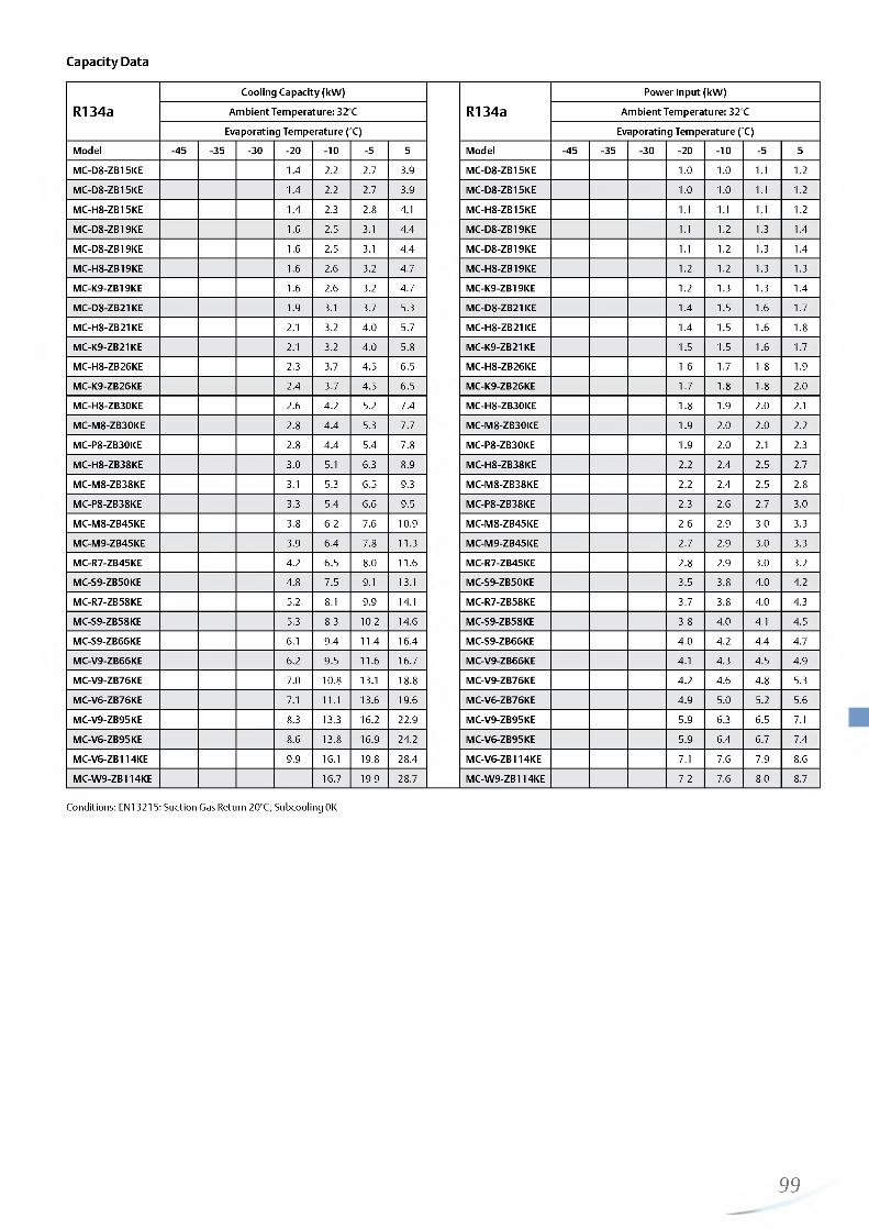
http://holodko.ru/
Capacity Data
R134aCooling Capacity (kW)
R134aPower Input (kW)
Ambient Temperature: 32°C Ambient Temperature: 32°C
Evaporating Temperature (°C) Evaporating Temperature (°C)
Model -45 -35 -30 -2 0 -1 0 -5 5 Model -45 -35 -30 -2 0 - 1 0 -5 5
MC-D8-ZB15KE 1.4 2.2 2.7 3.9 MC-D8-ZB15KE 1 .0 1.0 1 .1 1 .2
MC-D8-ZB15KE 1.4 2.2 2.7 3.9 MC-D8-ZB15KE 1 .0 1.0 1 .1 1 .2
MC-H8-ZB15KE 1.4 2.3 2.8 4.1 MC-H8-ZB15KE 1 .1 1 .1 1 .1 1 .2
MC-D8-ZB19KE 1 .6 2.5 3.1 4.4 MC-D8-ZB19KE 1 .1 1 .2 1.3 1.4
MC-D8-ZB19KE 1.6 2.5 3.1 4.4 MC-D8-ZB19KE 1 .1 1 .2 1.3 1.4
MC-H8-ZB19KE 1.6 2.6 3.2 4.7 MC-H8-ZB19KE 1 .2 1 .2 1.3 1.3
MC-K9-ZB19KE 1.6 2.6 3.2 4.7 MC-K9-ZB19KE 1 .2 1.3 1.3 1.4
MC-D8-ZB21KE 1.9 3.1 3.7 5.3 MC-D8-ZB21KE 1.4 1.5 1.6 1.7
MC-H8-ZB21KE 2.1 3.2 4.0 5.7 MC-H8-ZB21KE 1.4 1.5 1 .6 1.8
MC-K9-ZB21KE 2.1 3.2 4.0 5.8 MC-K9-ZB21KE 1.5 1.5 1 .6 1.7
MC-H8-ZB26KE 2.3 3.7 4.5 6.5 MC-H8-ZB26KE 1 .6 1.7 1 .8 1.9
MC-K9-ZB26KE 2.4 3.7 4.5 6.5 MC-K9-ZB26KE 1.7 1 .8 1 .8 2.0
MC-H8-ZB30KE 2.6 4.2 5.2 7.4 MC-H8-ZB30KE 1 .8 1.9 2.0 2.1
MC-M8-ZB30KE 2.8 4.4 5.3 7.7 MC-M8-ZB30KE 1.9 2.0 2.0 2.2
MC-P8-ZB30KE 2.8 4.4 5.4 7.8 MC-P8-ZB30KE 1.9 2.0 2.1 2.3
MC-H8-ZB38KE 3.0 5.1 6.3 8.9 MC-H8-ZB38KE 2.2 2.4 2.5 2.7
MC-M8-ZB38KE 3.1 5.3 6.5 9.3 MC-M8-ZB38KE 2.2 2.4 2.5 2.8
MC-P8-ZB38KE 3.3 5.4 6.6 9.5 MC-P8-ZB38KE 2.3 2.6 2.7 3.0
MC-M8-ZB45KE 3.8 6.2 7.6 10.9 MC-M8-ZB45KE 2.6 2.9 3.0 3.3
MC-M9-ZB45KE 3.9 6.4 7.8 11.3 MC-M9-ZB45KE 2.7 2.9 3.0 3.3
MC-R7-ZB45KE 4.2 6.5 8.0 1 1 .6 MC-R7-ZB45KE 2.8 2.9 3.0 3.2
MC-S9-ZB50KE 4.8 7.5 9.1 13.1 MC-S9-ZB50KE 3.5 3.8 4.0 4.2
MC-R7-ZB58KE 5.2 8.1 9.9 14.1 MC-R7-ZB58KE 3.7 3.8 4.0 4.3
MC-S9-ZB58KE 5.3 8.3 10 .2 14.6 MC-S9-ZB58KE 3.8 4.0 4.1 4.5
MC-S9-ZB66KE 6.1 9.4 11.4 16.4 MC-S9-ZB66KE 4.0 4.2 4.4 4.7
MC-V9-ZB66KE 6.2 9.5 1 1 .6 16.7 MC-V9-ZB66KE 4.1 4.3 4.5 4.9
MC-V9-ZB76KE 7.0 10 .8 13.1 18.8 MC-V9-ZB76KE 4.2 4.6 4.8 5.3
MC-V6-ZB76KE 7.1 1 1 . 1 13.6 19.6 MC-V6-ZB76KE 4.9 5.0 5.2 5.6
MC-V9-ZB95KE 8.3 13.3 16.2 22.9 MC-V9-ZB95KE 5.9 6.3 6.5 7.1
MC-V6-ZB95KE 8.6 13.8 16.9 24.2 MC-V6-ZB95KE 5.9 6.4 6.7 7.4
MC-V6-ZB114KE 9.9 16.1 19.8 28.4 MC-V6-ZB114KE 7.1 7.6 7.9 8.6
MC-W9-ZB114KE 16.7 19.9 28.7 MC-W9-ZB114KE 7.2 7.6 8.0 8.7
Conditions: EN13215: Suction Gas Return 20°C, Subcooling 0K
99

http://holodko.ru/
Capacity Data
R407ACooling Capacity (kW)
R407APower Input (kW)
Ambient Temperature: 32°C Ambient Temperature: 32°C
Evaporating Temperature (°C) Evaporating Temperature (°C)
Model -45 -35 -30 -2 0 - 1 0 -5 5 Model -45 -35 -30 -2 0 - 1 0 -5 5
Low Temperature Models Low Temperature Models
MC-D8-ZF09KE 1.9 2.3 3.4 4.7 5.3 MC-D8-ZF09KE 1.9 2.1 2.9 4.1 5.0
MC-H8-ZF09KE 1.9 2.3 3.5 4.9 5.8 7.7 MC-H8-ZF09KE 1.8 2.1 2.7 3.6 4.2 5.8
MC-H8-ZF11KE 2.1 2.7 4.0 5.7 6.7 9.0 MC-H8-ZF11KE 2.0 2.1 2.4 2.8 3.0 3.5
MC-H8-ZF13KE 2 .2 2.8 4.3 6.1 7.1 8.9 MC-H8-ZF13KE 2.3 2.4 2.8 3.1 3.3 3.6
MC-M8-ZF13KE 2 .2 2.8 4.4 6.3 7.3 9.2 MC-M8-ZF13KE 2 .2 2.3 2.6 2.9 3.1 3.3
MC-H8-ZF15KE 2.7 3.3 5.1 7.3 8.5 1 1 .0 MC-H8-ZF15KE 2.8 3.0 3.6 4.1 4.3 4.3
MC-M8-ZF15KE 2.8 3.4 5.3 7.6 8.9 11.5 MC-M8-ZF15KE 2.7 2.9 3.4 3.8 3.9 3.8
MC-M8-ZF18KE 3.3 4.1 6.2 8.8 10 .2 13.0 MC-M8-ZF18KE 3.2 3.5 4.2 4.7 4.9 4.5
MC-M9-ZF18KE 3.3 4.1 6.4 9.1 10 .6 13.7 MC-M9-ZF18KE 4.5 4.9 5.2 5.8
Medium Temperature Models Medium Temperature Models
MC-D8-ZB15KE 2.1 3.2 3.8 5.3 MC-D8-ZB15KE 1.7 1 .8 1.9 2.1
MC-H8-ZB15KE 2.2 3.5 4.2 5.9 MC-H8-ZB15KE 1.7 1.7 1 .8 1.9
MC-D8-ZB19KE 2.5 3.8 4.5 6.1 MC-D8-ZB19KE 2.0 2.2 2.3 2.5
MC-H8-ZB19KE 2.7 4.1 4.9 6.9 MC-H8-ZB19KE 1.9 2.1 2 .2 2.3
MC-K9-ZB19KE 2.7 4.1 4.9 6.8 MC-K9-ZB19KE 1.9 2.1 2 .1 2.3
MC-D8-ZB21KE 2.9 4.4 5.1 6.8 MC-D8-ZB21KE 2.5 2.8 3.0 3.3
MC-H8-ZB21KE 3.1 4.9 5.8 8.0 MC-H8-ZB21KE 2.3 2.6 2.7 2.8
MC-K9-ZB21KE 3.1 4.8 5.8 7.9 MC-K9-ZB21KE 2.3 2.6 2.7 2.8
MC-H8-ZB26KE 3.5 5.4 6.4 8.9 MC-H8-ZB26KE 2.6 2.9 3.0 3.4
MC-K9-ZB26KE 3.4 5.4 6.4 8.8 MC-K9-ZB26KE 2.6 2.9 3.0 3.4
MC-H8-ZB30KE 4.1 6.4 7.7 10.4 MC-H8-ZB30KE 3.2 3.5 3.8 4.3
MC-M8-ZB30KE 4.3 6.8 8.1 1 1 . 1 MC-M8-ZB30KE 3.0 3.3 3.5 3.9
MC-P8-ZB30KE 4.3 6.8 8.2 11.3 MC-P8-ZB30KE 3.0 3.3 3.4 3.8
MC-H8-ZB38KE 4.8 7.5 8.8 MC-H8-ZB38KE 4.0 4.6 4.9
MC-M8-ZB38KE 5.1 8.0 9.5 12 .8 MC-M8-ZB38KE 3.8 4.2 4.5 5.1
MC-P8-ZB38KE 5.1 8.0 9.6 13.0 MC-P8-ZB38KE 3.7 4.1 4.4 5.0
MC-M8-ZB45KE 5.8 8.8 10.3 13.7 MC-M8-ZB45KE 4.6 5.3 5.6 6.2
MC-M9-ZB45KE 6.0 9.3 1 1 .0 14.9 MC-M9-ZB45KE 4.5 5.1 5.3 5.8
MC-R7-ZB45KE 6.2 9.6 11.5 15.7 MC-R7-ZB45KE 4.5 4.9 5.1 5.5
Digital Medium Temperature Models Digital Medium Temperature Models
MC-M8-ZBD30 4.5 6.8 8.1 1 1 . 1 MC-M8-ZBD30 3.1 3.4 3.6 4.0
MC-M9-ZBD45 6.1 9.2 1 1 .0 14.9 MC-M9-ZBD45 3.1 3.4 3.6 4.0
MC-V6-ZBDT60 9.4 14.4 17.4 24.3 MC-V6-ZBDT60 6.0 6.4 6.7 7.3
MC-V6-ZBDT90 12.7 19.1 22 .8 31.4 MC-V6-ZBDT90 8.8 9.5 9.9 10.9
Conditions: EN13215: Suction Gas Return 20°C, Subcooling 0K
100
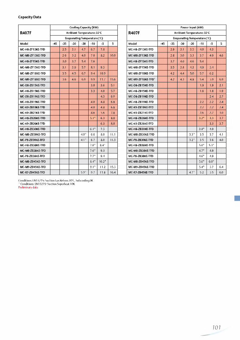
http://holodko.ru/
Capacity Data
R407FCooling Capacity (kW)
R407FPower Input (kW)
Ambient Temperature: 32°C Ambient Temperature: 32°C
Evaporating Temperature (°C) Evaporating Temperature (°C)Model -45 -35 -30 -2 0 - 1 0 -5 5 Model -45 -35 -30 -2 0 -1 0 -5 5
MC-H8-ZF13KE-TFD 2.5 3.1 4.7 6.7 7.8 MC-H8-ZF13KE-TFD 2.9 3.1 3.5 4.0 4.3
MC-M8-ZF13KE-TFD 2.6 3.2 4.9 7.0 8.2 10.9 MC-M8-ZF13KE-TFD 2.8 3.0 3.3 3.7 4.0 4.6
MC-H8-ZF15KE-TFD 3.0 3.7 5.4 7.6 MC-H8-ZF15KE-TFD 3.7 4.0 4.6 5.4
MC-M8-ZF15KE-TFD 3.1 3.9 5.7 8.1 9.5 MC-M8-ZF15KE-TFD 3.5 3.8 4.3 4.9 5.4
MC-M8-ZF18KE-TFD 3.5 4.5 6.7 9.4 10.9 MC-M8-ZF18KE-TFD 4.2 4.4 5.0 5.7 6.2
MC-M9-ZF18KE-TFD 3.6 4.6 6.9 9.9 11.7 15.6 MC-M9-ZF18KE-TFD* 4.2 4.3 4.8 5.4 5.9 6.9
MC-D8-ZB15KE-TFD 3.0 3.6 5.1 MC-D8-ZB15KE-TFD 1.9 1.9 2.1
MC-H8-ZB15KE-TFD 3.3 4.0 5.7 MC-H8-ZB15KE-TFD 1.8 1.8 1.9
MC-D8-ZB19KE-TFD 4.3 6.0 MC-D8-ZB19KE-TFD 2.4 2.7
MC-H8-ZB19KE-TFD 4.0 4.8 6.8 MC-H8-ZB19KE-TFD 2.2 2 .2 2.4
MC-K9-ZB19KE-TFD 4.0 4.8 6.8 MC-K9-ZB19KE-TFD 2.2 2 .2 2.4
MC-K9-ZB21KE-TFD 4.6 5.6 7.8 MC-K9-ZB21KE-TFD 2.6 2.7 3.0
MC-H8-ZB26KE-TFD 5.1* 6.3 8.8 MC-H8-ZB26KE-TFD 3.2* 3.3 3.7
MC-K9-ZB26KE-TFD 6.3 8.8 MC-K9-ZB26KE-TFD 3.3 3.7
MC-H8-ZB30KE-TFD 6 .1 * 7.5 MC-H8-ZB30KE-TFD 3.8* 4.0
MC-M8-ZB30KE-TFD 4.0* 6.6 8.0 1 1 . 1 MC-M8-ZB30KE-TFD 3.3* 3.5 3.7 4.1
MC-P8-ZB30KE-TFD 4.1* 6.7 8.0 11.3 MC-P8-ZB30KE-TFD 3.2* 3.5 3.6 4.0
MC-H8-ZB38KE-TFD 7.0* 8.4* MC-H8-ZB38KE-TFD 5.0* 5.3*
MC-M8-ZB38KE-TFD 7.6* 9.3 MC-M8-ZB38KE-TFD 4.7* 4.9
MC-P8-ZB38KE-TFD 7.7* 9.4 MC-P8-ZB38KE-TFD 4.6* 4.9
MC-M8-ZB45KE-TFD 8.4* 1 0 .2 * MC-M8-ZB45KE-TFD 5.6* 6 .0 *
MC-M9-ZB45KE-TFD 9.1* 1 1 . 2 15.5 MC-M9-ZB45KE-TFD 5.4* 5.7 6.4
MC-R7-ZB45KE-TFD 5.9* 9.7 1 1 .8 16.4 MC-R7-ZB45KE-TFD 4.7* 5.2 5.5 6.0
Conditions: EN13215: Suction Gas Return 20°C, Subcooling 0K* Conditions: EN13215: Suction Superheat 10K Preliminary data
101

http://holodko.ru/
Copeland Scroll Digital Receiver Units are the perfect choice for remote condenser systems.
These Scroll Digital Receiver Units are an innovative offering by Emerson Climate Technologies for food service and retail businesses. Their compact design and the power of Digital Scroll™ continuous capacity modulation allow for optimized environmental integration at highest system efficiency.
Eight models with single or tandem compressors cover the need of medium temperature refrigeration capacities in various applications. The continuous capacity modulation always provides the right performance, especially for systems with multiple evaporators and variable loads. The remote condenser concept allows for optimal building integration.
Copeland Scroll™ Digital Receiver Unit HLR
Digital Receiver Unit HLR
Digital Receiver Unit HLR Line-up
Tandem • • • •
Single • • • •
M ax. Capacity (kW )0 5 10 15 20 25 30 35
Conditions EN12900 R404A: Evaporating Temperature -10°C, Condensing Temperature 45°C, Suction Gas Return 20°C
Features and Benefits Maximum Allowable Pressures (PS)
Standard equipment: Digital Scroll™ compressor, liquid receiver, liquid line with filter drier and sight glass, HP/LP switch, complete electrical box including controller with overload protection and communication interface Continuous capacity modulation 10-100 % (Single) or 5-100 % (Tandem)Precise suction pressure controlMaximum system flexibility by free choice of third party condensersExcellent energy efficiencyHigh reliabilityEasy and quick installation
Low Side PS 22.5 bar (g)High Side PS = 28/32 bar (g)
102—

http://holodko.ru/
Technical Overview
R404A
Capa
city
(kW
)
Rece
iver
Capa
city
(l)
Sucti
on
Line
Diam
eter
(in
ch)
Liquid
Lin
e Di
amet
er (
inch
)
Width/Depth/Heigth(mm)
Net
Weig
ht (
kg) Motor Version/
CodeMaximum Operat
ing Current (A)Locked Rotor Cur
rent (A)Sound Pressure @1 m dB(A)***
1 Ph* 3 Ph** 1 Ph* 3 Ph** 1 Ph* 3 Ph**with
soundshell
Single Compressor Unit Models
HLR13-ZBD30KE 7.0 13.0 7/8” 5/8” 690/400/710 72 TFD 8 52 59 49
HLR13-ZBD45KE 10 .2 13.0 7/8” 5/8” 690/400/710 75 TFD 1 2 74 61 51
HLR13-ZBD58KE 13.5 13.0 1 1 /8” 3/4” 725/400/710 84 TFD 15 95 65 55
HLR13-ZBD76KE 17.8 13.0 1 3/8” 3/4” 725/400/710 90 TFD 20 118 66 56
Tandem Compressor Unit Models
HLR31-ZBDT60KE 14.1 31.0 1 3/8” 7/8” 970/480/910 130 TFD 8 + 8 52 + 52 62 -
HLR31-ZBDT90KE 20.3 31.0 1 3/8” 7/8” 970/480/910 138 TFD 1 2 + 1 2 74 + 74 64 -
HLR31-ZBDT116KE 26.8 31.0 1 5/8” 1 1 /8 ” 970/480/870 165 TFD 15 + 15 95 + 95 68 -
HLR31-ZBDT152KE 35.7 31.0 1 5/8” 1 3/8” 970/480/870 175 TFD 20 + 20 118 + 118 69 -
Conditions EN12900: R404A, Evaporating Temperature -10°C, Condensing Temperature 45°C, Suction Gas Return 20°C
* 1 Ph: 230V/ 50Hz ** 3 Ph: 380-420V/ 50Hz*** @ 1 m: sound pressure level at 1 m distance from the compressor, free field condition
Capacity Data
R404A
Cooling Capacity (kW)
R404A
Power Input (kW)
Condensing Temperature: 45°C Condensing Temperature: 45°C
Evaporating Temperature (°C) Evaporating Temperature (°C)
-45 -35 -30 -2 0 - 1 0 -5 5 -45 -35 -30 -2 0 - 1 0 -5 5
Single Compressor Units Single Compressor Units
HLR13-ZBD30KCE 2.7* 4.8 7.0 8.4 1 1 .8 HLR13-ZBD30KCE 2. 2.9 3.1 3.2 3.5
HLR13-ZBD45KCE 3.4* 6.6 10 .2 12.5 18.0 HLR13-ZBD45KCE 4. 4.6 4.8 4.9 5.2
HLR13-ZBD58KCE 8.6 13.5 16.3 22.9 HLR13-ZBD58KCE 6.4 6.4 6.4 6.4
HLR13-ZBD76KCE 1 1 .8 17.9 21.4 30.2 HLR13-ZBD76KCE 8.1 8.3 8.3 8.4
Tandem Compressor Units Tandem Compressor Units
HLR31-ZBDT60KCE 5. 9.6 14.1 16.9 23.6 HLR31-ZBDT60KCE cn4. 5.8 6.3 6.5 6.9
HLR31-ZBDT90KCE o7. 13.4 20.3 24.5 35.0 HLR31-ZBDT90KCE CN9. 9.4 9.6 9.7 9.9
HLR31-ZBDT116KE 6. 17.0 26.7 32.4 45.8 HLR31-ZBDT116KE 13.1* 12.7 12.7 12.7 12 .8
HLR31-ZBDT152KE 23.7 35.7 42.9 60.3 HLR31-ZBDT152KE 16.2 16.4 16.5 16.8
Conditions: EN12900: Condensing Temperature 45°C, Suction Gas Return 20°C, Subcooling 0K* Conditions:EN12900: Condensing Temperature 45°C, Suction Superheat 10K
103

http://holodko.ru/
Capacity Data
R407ACooling Capacity (kW)
R407APower Input (kW)
Condensing Temperature: 40°C Condensing Temperature: 40°C
Evaporating Temperature (°C) Evaporating Temperature (°C)Model -45 -35 -30 -2 0 - 1 0 -5 5 Model -45 -35 -30 -2 0 - 1 0 -5 5
HLR13-ZBD30KCE 4.6 7.3 9.0 13.1 HLR13-ZBD30KCE 2.8 2.8 2.8 2.8
HLR13-ZBD45KCE 6.4 10 .1 12.5 18.3 HLR13-ZBD45KCE 3.8 3.8 3.9 3.9
HLR31-ZBDT60KCE 9.2 14.6 18.0 26.1 HLR31-ZBDT60KCE 5.4 5.5 5.6 5.6
HLR31-ZBDT90KCE 13.0 20.3 24.9 36.3 HLR31-ZBDT90KCE 7.8 7.8 7.8 7.8
Conditions: EN12900: Condensing Temperature 45°C Suction Gas Return 20°C, Subcooling 0K Preliminary data
R407FCooling Capacity (kW)
R407FPower Input (kW)
Condensing Temperature: 40°C Condensing Temperature: 40°C
Evaporating Temperature (°C) Evaporating Temperature (°C)Model -45 -35 -30 -2 0 -1 0 -5 5 Model -45 -35 -30 -2 0 -1 0 -5 5
HLR13-ZBD30KCE 2 .8 * 4.8 7.3 8.8 12 .8 HLR13-ZBD30KCE 2 .0 * 2.5 2.8 2.9 3.1
HLR13-ZBD45KCE 6.4* 10 .8 13.2 18.9 HLR13-ZBD45KCE 3.7* 4.1 4.3 4.6
HLR31-ZBDT60KCE 8.9* 14.5 17.7 25.7 HLR31-ZBDT60KCE 5.4* 5.7 5.8 6.0
HLR31-ZBDT90KCE 12.4* 2 1 .2 26.1 37.9 HLR31-ZBDT90KCE 7.8* 8.4 8.5 8.8
Conditions: EN12900: Condensing Temperature 45°C, Suction Gas Return 20°C, Subcooling 0K *Conditions: EN12900: Condensing Temperature 45°C, Suction Superheat 10K
104

http://holodko.ru/

http://holodko.ru/
Semi-Hermetic Condensing Units DK/DL
Copeland™ air-cooled indoor condensing units for medium temperature and low temperature applications.
Long-term engineering and manufacturing experience has led to these condensing units with reed valve technology compressors.Their excellent quality and reliability is traditionally well known in the refrigeration industry.
This series of condensing units is equipped with single fan or twin fans which allows for very compact dimensions. The wide range of models offers solutions for most applications including operation in extreme conditions like high evaporation temperatures and high ambient temperatures.
Semi-Hermetic Condensing Unit DK/DL
Semi-Hermetic DK/DL Condensing Units Medium Temperature Line-up
DL-Series• • • • • • •
DK-Series • • • • •
Capacity (kW ) 1 1 10 1 2 3 4 5 6 7 8 9 10
Conditions EN13215 R404A: Evaporating Temperature -10°C, Suction Gas Return 20°C, Subcooling 0K
Semi-Hermetic DK/DL Condensing Units Low Temperature Line-up
DL-Series • • • • • • • • • •
DK-Series • • • • • •
Capacity (kW ) 1 10 1 2 3 4 5
Conditions EN13215 R404A: Evaporating Temperature -45°C, Suction Gas Return 20°C, Subcooling 0K
Features and Benefits Maximum Allowable Pressures (PS)
Standard equipment: compressor, condenser with thermally protected fan(s), discharge line with flexible pipe loop or vibration absorber, liquid receiver with shut-off-valve, HP/LP switch with automatic resetSuitable for a broad range of refrigerants: R404A, R507,R134a, R407A/C, R22Wide range of quality accessoriesProven reliability
Low Side PS 22.5 bar (g) High Side PS = 28 bar (g)
106—
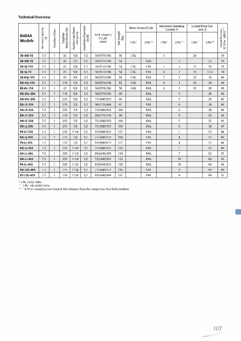
http://holodko.ru/
Technical Overview
R404AModels
Rece
iver
Capa
city
(l)
Num
ber
of fa
ns
Tota
l Fan
Mot
or P
ower
(W
)
Sucti
on
Line
Diam
ete
r (in
ch)
Liquid
Lin
e Di
amet
er
(inch
) Width/Depth/Height(mm)
Net
Wei
ght
(kg)
Motor Version/Code Maximum Operating Current, A
Locked Rotor Current, A
Soun
d Pr
essu
re@
10 m
- d(B
A)**
*
1 Ph* 3 Ph** 1 Ph* 3 Ph** 1 Ph* 3 Ph**
B8-KM-5X 3.1 1 85 5/8 1 /2 560/570/396 56 CAG 5 24 39
B8-KM-7X 3.1 1 85 1 /2 1 /2 560/570/396 58 EWL 2 1 2 39
B8-KJ-10X 3.1 1 85 5/8 1 /2 560/570/396 58 CAG EWL 7 3 32 16 39
B8-KJ-7X 3.1 1 85 5/8 1 /2 560/570/396 58 CAG EWL 6 2 35 12 ,0 39
B8-KSJ-10X 3.1 1 85 5/8 1 /2 560/570/396 58 CAG EWL 7 3 32 16 46
D8-KSJ-15X 3.7 1 1 1 0 7/8 1 /2 560/570/446 62 CAG EWL 9 3 43 20 46
B8-KL-15X 3.1 1 85 5/8 1 /2 560/570/396 58 CAG EWL 8 3 43 20 40
D8-KSL-20X 3.7 1 1 1 0 5/8 1 /2 560/570/396 60 EWL 5 20 46
H8-KSL-20X 7.5 1 235 5/8 1 /2 735/680/533 60 EWL 5 20 49
D8-LE-20X 3.7 1 1 1 0 7/8 1 /2 560/715/446 97 EWL 6 38 46
H8-LE-20X 7.5 1 235 7/8 1 /2 735/680/533 108 EWL 6 38 49
D8-LF-20X 3.7 1 1 1 0 7/8 1 /2 560/715/446 98 EWL 5 38 46
H8-LF-30X 7.5 1 235 7/8 1 /2 735/680/533 108 EWL 7 53 49
H8-LJ-20X 7.5 1 235 7/8 1 /2 735/680/533 103 EWL 6 38 49
P8-LF-30X 7.5 22 0 1 1 /8 1 /2 950/640/633 127 EWL 7 53 48
H8-LJ-30X 7.5 1 235 7/8 1 /2 735/680/533 108 EWL 8 53 49
P8-LJ-30X 7.5 22 0 7/8 1 /2 950/640/633 127 EWL 8 53 48
H8-LL-30X 7.5 1 235 1 1 /8 1 /2 735/680/533 1 1 0 EWL 7 53 49
K9-LL-30X 7.5 22 0 1 1 /8 1 /2 950/640/454 134 EWL 7 53 47
H8-LL-40X 7.5 1 235 1 1 /8 1 /2 735/680/533 1 1 2 EWL 10 69 49
P8-LL-40X 7.5 22 0 1 1 /8 1 /2 950/640/633 128 EWL 10 69 48
H8-LSG-40X 7.5 1 235 1 1 /8 1 /2 735/680/533 116 EWL 9 69 49
K9-LSG-40X 7.5 2 2 2 0 1 1 /8 1 /2 950/640/454 131 EWL 9 69 51
* 1 Ph: 230V/ 50Hz** 3 Ph: 380-420V/ 50Hz*** @ 10 m: sound pressure level at 1 0 m distance from the compressor, free field condition
107

http://holodko.ru/
Capacity Data
R404AAmbient Temperature +32°C
Cooling Capacity (kW)R404A
Power Input (kW)
Evaporation Temperature (°C) Evaporation Temperature (°C)
Model -45 -35 -30 -2 0 -1 0 -5 5 Model -45 -35 -30 -2 0 - 1 0 -5 5
B8-KM-5X 0.3 0.6 0.8 1.3 B8-KM-5X 0.5 0.6 0.6 0.8
B8-KM-7X 0.3 0.6 0.8 1.3 1.9 2.2 3.0 B8-KM-7X 0.4 0.6 0.7 0.8 1.0 1 .1 1.3
B8-KJ-10X 0.4 0.8 1 .1 1.7 2.4 2.8 3.6 B8-KJ-10X 0.5 0.8 0.9 1 .1 1.4 1.5 1.8
B8-KJ-7X 0.4 0.8 1 .1 1.7 B8-KJ-7X 0.6 0.8 0.9 1 .1
B8-KSJ-10X 0.6 1 .1 1.3 1.8 B8-KSJ-10X 0.8 1.0 1 .2 1.5
D8-KSJ-15X 0.6 1 .1 1.4 2.2 3.2 3.8 D8-KSJ-15X 0.7 1 .0 1 .1 1.4 1.8 1.9
B8-KL-15X 0.7 1 .2 1.5 2.3 B8-KL-15X 0.9 1 .1 1.3 1.6
D8-KSL-20X 0.9 1 .6 2.0 3.1 4.3 D8-KSL-20X 1.0 1.3 1.5 2.0 2.6
H8-KSL-20X 0.9 1.7 2.2 3.3 4.8 5.7 H8-KSL-20X 1 .1 1.5 1.7 2.1 2.6 2.8
D8-LE-20X 1 .2 1.7 2.9 4.3 5.0 D8-LE-20X 1 .1 1.3 1.7 2.2 2.5
H8-LE-20X 1.3 1.9 3.2 4.8 5.8 7.8 H8-LE-20X 1 .2 1.4 1.9 2.3 2.5 3.0
D8-LF-20X 0.7 1.7 2.2 3.5 D8-LF-20X 1.0 1.5 1 .8 2.4
H8-LF-30X 0.9 2.1 2.7 4.4 6.3 7.4 H8-LF-30X 1.3 1.9 2.1 2.7 3.3 3.6
P8-LF-30X 1.0 2 .1 2.9 4.7 6.9 8.2 1 1 . 1 P8-LF-30X 1.3 1.9 2.1 2.6 3.2 3.4 4.0
H8-LJ-20X 0.8 2.1 2.9 H8-LJ-20X 1 .2 1.8 2 .2
H8-LJ-30X 1 .1 2.3 3.0 4.7 6.8 7.9 H8-LJ-30X 1.4 2.0 2.4 3.0 3.8 4.2
P8-LJ-30X 1 .1 2.4 3.2 5.1 7.5 8.9 11.9 P8-LJ-30X 1.4 2.0 2.3 3.0 3.6 4.0 4.6
H8-LL-30X 1 .2 2.7 3.6 5.7 H8-LL-30X 1.5 2.2 2.7 3.6
H8-LL-40X 1.4 2.8 3.6 5.6 8.1 9.4 H8-LL-40X 1.7 2.4 2.8 3.7 4.7 5.3
K9-LL-30X 1 .2 2.7 3.6 5.7 K9-LL-30X 1.5 2.2 2.6 3.6
P8-LL-40X 1.4 2.9 3.9 6.2 9.1 10 .8 P8-LL-40X 1.7 2.4 2.8 3.6 4.5 5.0
H8-LSG-40X 1.7 3.4 4.4 6.7 H8-LSG-40X 1.9 2.8 3.3 4.5
K9-LSG-40X 1.7 3.4 4.4 6.7 K9-LSG-40X 1.9 2.8 3.3 4.5
Conditions: EN13215: Suction Gas Return 20°C, Subcooling 0K
R134aCooling Capacity (kW)
R134aPower Input (kW)
Ambient Temperature: 32°C Ambient Temperature: 32°C
Evaporating Temperature (°C) Evaporating Temperature (°C)
Model -45 -35 -30 -2 0 -1 0 -5 5 Model -45 -35 -30 -2 0 - 1 0 -5 5
B8-KM-5X 0.8 1 .2 1.5 2.2 B8-KM-5X 0.5 0.6 0.7 0.8
B8-KJ-7X 1.0 1.6 1.9 2.8 B8-KJ-7X 0.7 0.8 0.9 1 .0
B8-KSJ-10X 1 .2 1.9 2.4 3.4 B8-KSJ-10X 0.8 0.9 1.0 1 .2
B8-KL-15X 1.4 2.2 2.6 3.7 B8-KL-15X 0.9 1 .2 1.3 1 .6
D8-KSL-15X 1.8 2.8 3.4 4.9 D8-KSL-15X 1 .1 1.4 1.6 1.9
D8-KSL-20X 1.8 2.9 3.5 5.0 D8-KSL-20X 1 .1 1.4 1.5 1.8
H8-KSL-20X 1.9 3.0 3.7 5.4 H8-KSL-20X 1 .2 1.5 1.6 1.8
D8-LE-20X 1.6 2.7 3.4 4.9 D8-LE-20X 1 .1 1.4 1.5 1.8
H8-LE-20X 1.7 2.9 3.6 5.4 H8-LE-20X 1 .2 1.5 1.6 1.8
D8-LF-20X 2 .2 3.6 4.4 6 .2 D8-LF-20X 1.4 1.7 1.9 2.3
H8-LJ-20X 2.7 4.3 5.2 7.5 H8-LJ-20X 1 .8 2.2 2.4 2.8
H8-LL-30X 3.2 5.3 6.5 9.2 H8-LL-30X 2.1 2.6 3.0 3.7
K9-LL-30X 3.2 5.3 6.5 9.3 K9-LL-30X 2.1 2.6 2.9 3.7
H8-LSG-40X 4.2 6.6 7.9 1 1 .0 H8-LSG-40X 2.5 3.2 3.7 4.6
K9-LSG-40X 4.2 6.6 8.0 1 1 . 1 K9-LSG-40X 2.5 3.2 3.6 4.5
Conditions: EN13215: Suction Gas Return 20°C, Subcooling 0K
108
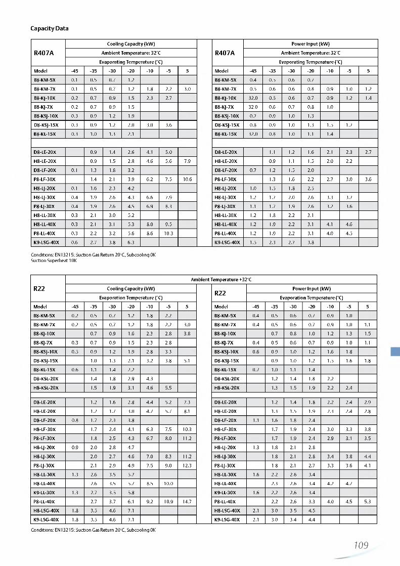
http://holodko.ru/
Capacity Data
R407ACooling Capacity (kW)
R407APower Input (kW)
Ambient Temperature: 32°C Ambient Temperature: 32°C
Evaporating Temperature (°C) Evaporating Temperature (°C)
Model -45 -35 -30 -2 0 -1 0 -5 5 Model -45 -35 -30 -2 0 - 1 0 -5 5
B8-KM-5X 0.1 0.5 0.7 1 .2 B8-KM-5X 0.4 0.5 0.6 0.7
B8-KM-7X 0.1 0.5 0.7 1 .2 1.8 2.2 3.0 B8-KM-7X 0.5 0.6 0.6 0.8 0.9 1 .0 1 .2
B8-KJ-10X 0 .2 0.7 0.9 1.5 2.3 2.7 B8-KJ-10X 32.0 0.5 0.6 0.7 0.9 1 .2 1.4
B8-KJ-7X 0 .2 0.7 0.9 1.5 B8-KJ-7X 32.0 0.6 0.7 0.8 1.0
B8-KSJ-10X 0.3 0.9 1 .2 1.9 B8-KSJ-10X 0.7 0.9 1.0 1.3
D8-KSJ-15X 0.3 0.9 1 .2 2.0 3.0 3.6 D8-KSJ-15X 0.8 0.9 1.0 1.3 1.5 1.7
B8-KL-15X 0.3 1 .0 1.3 2.1 B8-KL-15X 32.0 0.8 1.0 1 .1 1.4
D8-LE-20X 0.9 1.4 2.6 4.1 5.0 D8-LE-20X 1 .1 1 .2 1.6 2.1 2.3 2.7
H8-LE-20X 0.9 1.5 2.8 4.6 5.6 7.9 H8-LE-20X 0.9 1 .1 1.5 2.0 2.2
D8-LF-20X 0.1 1.3 1.8 3.2 D8-LF-20X 0.7 1 .2 1.5 2.0
P8-LF-30X 1.4 2.1 3.9 6.2 7.5 10 .6 P8-LF-30X 1.3 1 .6 2.2 2.7 3.0 3.6
H8-LJ-20X 0.1 1.6 2.3 4.2 H8-LJ-20X 1.0 1.5 1.8 2.5
H8-LJ-30X 0.4 1.9 2.6 4.3 6.6 7.9 H8-LJ-30X 1 .2 1.7 2.0 2.6 3.3 3.7
P8-LJ-30X 0.4 1.9 2.6 4.5 6.9 8.3 P8-LJ-30X 1 .1 1.7 1.9 2.6 3.2 3.6
H8-LL-30X 0.3 2.1 3.0 5.2 H8-LL-30X 1 .2 1.8 2 .2 3.1
H8-LL-40X 0.3 2.1 3.1 5.3 8.0 9.5 H8-LL-40X 1 .2 1.9 2.2 3.1 4.1 4.6
P8-LL-40X 0.3 2.2 3.2 5.6 8.6 10.3 P8-LL-40X 1 .2 1.9 2.2 3.1 4.0 4.5
K9-LSG-40X 0.6 2.7 3.8 6.3 K9-LSG-40X 1.5 2.3 2.7 3.8
Conditions: EN13215: Suction Gas Return 20°C, Subcooling 0K Suction Superheat 10K
R22Ambient Temperature +32°C
Cooling Capacity (kW)R22
Power Input (kW)
Evaporation Temperature (°C) Evaporation Temperature (°C)
Model -45 -35 -30 -2 0 -1 0 -5 5 Model -45 -35 -30 -2 0 - 1 0 -5 5
B8-KM-5X 0 .2 0.5 0.7 1 .2 1.8 2 .2 B8-KM-5X 0.4 0.5 0.6 0.7 0.9 1.0
B8-KM-7X 0 .2 0.5 0.7 1 .2 1.8 2 .2 3.0 B8-KM-7X 0.4 0.5 0.6 0.7 0.9 1.0 1 .1
B8-KJ-10X 0.7 0.9 1 .6 2.3 2.8 3.8 B8-KJ-10X 0.7 0.8 1.0 1 .2 1.3 1.5
B8-KJ-7X 0.3 0.7 0.9 1.5 2.3 2.8 B8-KJ-7X 0.4 0.5 0.6 0.7 0.9 1.0 1 .1
B8-KSJ-10X 0.5 0.9 1 .2 1.9 2.8 3.3 B8-KSJ-10X 0.6 0.9 1 .0 1 .2 1 .6 1.8
D8-KSJ-15X 1.0 1.3 2.1 3.2 3.8 5.1 D8-KSJ-15X 0.9 1 .0 1 .2 1.5 1.6 1.8
B8-KL-15X 0.6 1 .1 1.4 2 .2 B8-KL-15X 0.7 1 .0 1 .1 1.4
D8-KSL-20X 1.4 1 .8 2.9 4.3 D8-KSL-20X 1 .2 1.4 1 .8 2 .2
H8-KSL-20X 1.5 1.9 3.1 4.6 5.5 H8-KSL-20X 1.3 1.5 1.9 2 .2 2.4
D8-LE-20X 1 .2 1.6 2.8 4.4 5.2 7.3 D8-LE-20X 1 .2 1.4 1 .8 2 .2 2.4 2.9
H8-LE-20X 1 .2 1.7 3.0 4.7 5.7 8.1 H8-LE-20X 1.3 1.5 1.9 2.3 2.4 2.8
D8-LF-20X 0.8 1.7 2.3 3.8 D8-LF-20X 1 .1 1.6 1.8 2.4
H8-LF-30X 1.7 2.4 4.1 6.3 7.5 10.3 H8-LF-30X 1.7 1.9 2.4 3.0 3.3 3.8
P8-LF-30X 1 .8 2.5 4.3 6.7 8.0 1 1 .2 P8-LF-30X 1.7 1.9 2.4 2.9 3.1 3.5
H8-LJ-20X 0.9 2.0 2.8 4.7 H8-LJ-20X 1.3 1 .8 2.1 2.8
H8-LJ-30X 2.0 2.7 4.6 7.0 8.3 1 1 .2 H8-LJ-30X 1 .8 2.1 2.8 3.4 3.8 4.4
P8-LJ-30X 2.1 2.9 4.9 7.5 9.0 12.3 P8-LJ-30X 1 .8 2.1 2.7 3.3 3.6 4.1
H8-LL-30X 1.3 2.6 3.5 5.7 H8-LL-30X 1 .6 2.2 2.6 3.4
H8-LL-40X 2.6 3.5 5.7 8.5 10 .0 H8-LL-40X 2.3 2.6 3.4 4.2 4.7
K9-LL-30X 1.3 2.7 3.5 5.8 K9-LL-30X 1 .6 2.2 2.6 3.4
P8-LL-40X 2.7 3.7 6.1 9.2 10.9 14.7 P8-LL-40X 2.2 2.6 3.3 4.0 4.5 5.3
H8-LSG-40X 1.8 3.5 4.6 7.1 H8-LSG-40X 2.1 3.0 3.5 4.5
K9-LSG-40X 1.8 3.5 4.6 7.1 K9-LSG-40X 2.1 3.0 3.4 4.4
Conditions: EN13215: Suction Gas Return 20°C, Subcooling 0K
109

http://holodko.ru/
Standard Semi-Hermetic Condensing Units
Copeland™ air-cooled indoor condensing units for medium temperature and low temperature applications.
Long-term engineering and manufacturing experience has led to this complete range of condensing units featuring semi-hermetic reciprocating compressor technology for use in high, medium and low temperature applications. Their excellent quality and reliability is traditionally well known in the refrigeration industry.
This series is equipped with compressors using reed valve technology which provide 0.5 to 40 hp motor power. The wide range of models offers solutions for most applications including operation in extreme conditions like high evaporation temperatures and high ambient temperatures.
Standard Units Line-up
Standard Semi-Hermetic Condensing Units
Medium Temperature • • * M • • M • M
Low Temperature
Capacity (kW )
• • • • • • •
10 15 20 25 30 35 40 45 50 55 60
Conditions EN13215 R404A: Evaporating Temperature LT -45°C/MT -10°C, Suction Gas Return 20°C, Subcooling 0K
Features and Benefits
• Standard equipment: compressor, condenser with thermally protected fan(s), discharge line with flexible pipe loop or vibration absorber, liquid receiver with shut-off-valve, HP/LP switch with automatic reset, oil pressure safety control OPS2
• Multiple choice of refrigerants incl. R404A, R134a and R22• Robust design with good component accessibility• Wide range of quality accessories• Proven reliability
Maximum Allowable Pressures (PS)
• Low Side PS 22.5 bar (g)• High Side PS = 28 bar (g)
0 5
110

http://holodko.ru/
Technical Overview
R404A
Rece
iver
Capa
city
(l)
Num
ber
of fa
ns
Tota
l Fan
Mot
or P
ower
(W
)
Sucti
on
Line
Diam
eter
(in
ch)
Liquid
Lin
e Di
amet
er (
inch
)
Width/Depth/Height(mm)
Net
Wei
ght
(kg)
Motor Version/ Code
Maximum Operating Current,
ALocked Rotor Current, A
re ** ur )*Irt <C<S “ £ ^ ̂ E uno 10 ̂@3 Ph** 3 Ph** 3 Ph**
M8 - 2SA - 45X 7.9 1 235 1 1 /8 1 /2 735/730/708 150 EWL 1 1 69 49
R7 - 2SA - 45X 15.8 2 470 1 1 /8 3/4 1130/820/633 150 EWL 1 1 69 53
M9 - 2SA - 55X 7.9 1 400 1 1 /8 1 /2 735/730/708 149 EWL 13 67 50
M9 - 2SC - 55X 7.9 1 400 1 1 /8 1 /2 735/730/708 150 EWL 13 74 50
S9 - 2SC - 55X 15.8 2 470 1 1 /8 3/4 1130/820/708 150 EWL 13 74 53
S9 - 2SC - 65X 15.8 2 470 1 1 /8 3/4 1130/820/708 161 EWL 16 85 53
M9 - 2SK - 65X 7.9 1 400 1 1 /8 1 /2 735/730/708 150 EWL 16 85 52
V9 - 2SK - 65X 18.9 2 470 1 1 /8 7/8 1330/820/835 150 EWL 16 85 54
V9 - 3SA - 75X 18.9 2 470 1 3/8 7/8 1330/820/835 215 AWM 18 82 55
S9 - 3SC - 75X 15.8 2 470 1 3/8 3/4 1130/820/708 243 AWM 19 82 52
V6 - 3SC - 75X 18.9 2 800 1 3/8 7/8 1330/820/835 280 AWM 19 82 56
V6 - 3SC- 100X 18.9 2 800 1 3/8 7/8 1330/820/835 280 AWM 2 2 106 56
V6 - 3SS- 100X 18.9 2 800 1 3/8 7/8 1330/820/835 280 AWM 26 109 56
W9 - 3SS - 100X 18.9 2 800 1 3/8 7/8 1640/820/869 303 AWM 26 109 56
W9 - 3SS - 150X 18.9 2 800 1 5/8 7/8 1640/820/869 303 AWM 30 125 57
V6 - 4SL- 150X 18.9 2 800 1 5/8 7/8 1289/955/835 280 AWM 36 156 56
W9 - 4SA - 200X 18.9 2 800 1 5/8 7/8 1600/1108/875 303 AWM 32 175 57
Z9 - 4SA - 200X 18.9 4 1600 1 5/8 7/8 1600/1108/1252 280 AWM 32 175 52
W9 - 4ST - 200X 18.9 2 800 2 1 /8 7/8 1600/1108/875 303 AWM 42 175 56
Z9 - 4SH - 250X 18.9 4 1600 2 1 /8 7/8 1600/1108/1252 215 AWM 42 199 55
Z9 - 4SJ - 300X 18.9 4 1600 2 1 /8 7/8 1600/1108/1252 215 AWM 48 2 2 1 55
Z9-6SL- 250X 18.9 4 1600 2 1 /8 7/8 1600/1128/1252 215 AWM 57 199 55
Z9 - 6ST - 320X 18.9 4 1600 2 1 /8 7/8 1600/1128/1252 215 AWM 63 255 55
W99- 6SJ - 400X 44.0 4 1600 2 1 /8 7/8 1600/1200/1810 303 AWM 75 304 57
** 3 Ph: 380-420V/ 50Hz*** @ 10 m: sound pressure level at 1 0 m distance from the compressor, free field condition
111
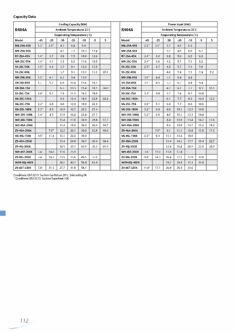
http://holodko.ru/
Capacity Data
R404ACooling Capacity (kW)
R404APower Input (kW)
Ambient Temperature: 32°C Ambient Temperature: 32°C
Evaporating Temperature (°C) Evaporating Temperature (°C)
Model -45 -35 -30 -2 0 - 1 0 -5 5 Model -45 -35 -30 -2 0 -1 0 -5 5
M8-2SA-45X 1.3* 2.9* 4.5 6.8 9.4 M8-2SA-45X 2 .2 * 3.1* 3.7 4.9 6.2
M9-2SA-55X 4.7 7.3 10.3 1 1 .8 M9-2SA-55X 3.7 4.9 6.0 6.7
R7-2SA-45X 1.4* 3.7 4.9 7.5 10 .8 12 .6 R7-2SA-45X 2.4* 3.4 3.9 5.0 6.2 6.8
M9-2SC-55X 1.4* 4.1 5.3 8.3 1 1 .6 13.5 M9-2SC-55X 2.4* 3.6 4.2 5.7 7.3 8.2
S9-2SC-55X 1.5* 4.3 5.7 9.1 13.2 15.5 S9-2SC-55X 2.5* 3.7 4.3 5.7 7.1 7.9
S9-2SC-65X 5.7 9.1 13.1 15.3 20.1 S9-2SC-65X 4.6 5.8 7.1 7.8 9.2
M9-2SK-65X 1.5* 4.7 6 .2 9.4 13.0 M9-2SK-65X 3.0* 4.4 5.1 6.8 8.8
V9-2SK-65X 1.7* 5.2 6.9 10 .8 15.6 18.3 V9-2SK-65X 3.1* 4.5 5.2 6.7 8.4 9.4
V9-3SA-75X 6.5 10.5 15.4 18.1 24.0 V9-3SA-75X 4.7 6.1 7.7 8.5 10 .1
S9-3SC-75X 2 .0 * 5.7 7.4 11.5 16.3 19.0 S9-3SC-75X 3.3* 4.8 5.7 7.6 9.7 10 .8
V6-3SC-100X 8.4 13.4 19.4 22 .8 30.3 V6-3SC-100X 6.1 7.7 9.5 10.4 1 2 .2
V6-3SC-75X 2 .2 * 6.0 8.0 12 .8 18.9 22.3 V6-3SC-75X 3.6* 5.1 6.0 7.7 9.6 10 .6
V6-3SS-100X 3.3* 8.5 10.9 16.7 23.5 27.4 V6-3SS-100X 5.2* 6.9 8.0 10.5 13.3 14.9
W9-3SS-100X 3.4* 8.5 1 1 .0 16.8 23.8 27.7 W9-3SS-100X 5.2* 6.9 8.0 10.5 13.3 14.8
W9-3SS-150X 11.4 17.6 24.9 28.9 37.7 W9-3SS-150X 8.4 10 .8 13.4 14.7 17.6
W9-4SA-200X 11.4 18.0 26.0 30.4 39.7 W9-4SA-200X 8.3 10.9 13.7 15.2 18.3
Z9-4SA-200X 7.6* 12.3 20 .1 30.0 35.8 49.0 Z9-4SA-200X 7.9* 9.1 11.5 13.8 15.0 17.2
V6-4SL-150X 4.5* 1 1 .8 15.1 22 .6 30.9 V6-4SL-150X 6.5* 9.4 1 1 . 1 14.8 19.0
Z9-4SH-250X 15.4 24.9 36.7 43.4 58.4 Z9-4SH-250X 11.4 14.5 17.7 19.4 22.7
Z9-4SJ-300X 18.5 29.7 43.0 50.3 65.9 Z9-4SJ-300X 12 .8 16.8 20.9 22.9 26.9
W9-4ST-200X 5.8* 14.0 17.6 25.9 W9-4ST-200X 7.6* 1 1 .0 13.0 17.4
Z9-6SL-250X 7.4* 18.3 23.5 35.6 49.5 57.0 Z9-6SL-250X 9.9* 14.3 16.8 22 .1 27.9 30.9
W99-6SJ-400X 26.1 40.7 56.9 65.4 W99-6SJ-400X 18.2 24.4 31.3 35.0
Z9-6ST-320X 7.8* 21.5 27.7 41.9 58.1 Z9-6ST-320X 1 1 .8 * 17.1 20.0 26.4 33.6
Conditions: EN13215: Suction Gas Return 20°C, Subcooling 0K* Conditions: EN13215: Suction Superheat 10K
112

http://holodko.ru/
Capacity Data
R134aCooling Capacity (kW)
R134aPower Input (kW)
Ambient Temperature: 32°C Ambient Temperature: 32°C
Evaporating Temperature (°C) Evaporating Temperature (°C)
Model -45 -35 -30 -2 0 - 1 0 -5 5 Model -45 -35 -30 -2 0 -1 0 -5 5
M8-2SA-45X 6.6 8.1 1 1 .6 M8-2SA-45X 3.4 3.7 4.4
R7-2SA-45X 7.0 8.6 12.7 R7-2SA-45X 3.5 3.8 4.4
M9-2SC-55X 8.1 9.8 13.9 M9-2SC-55X 4.1 4.6 5.5
S9-2SC-55X 8.5 10.4 15.0 S9-2SC-55X 4.1 4.5 5.3
M9-2SK-65X 8.9 10 .8 15.2 M9-2SK-65X 4.7 5.2 6.4
V9-2SK-65X 9.5 1 1 .8 17.1 V9-2SK-65X 4.6 5.0 5.9
S9-3SC-75X 10.9 13.3 19.1 S9-3SC-75X 5.4 6.0 7.4
V6-3SC-75X 1 1 .6 14.3 2 1 .1 V6-3SC-75X 5.6 6.1 7.4
V6-3SS-100X 14.8 18.2 26.3 V6-3SS-100X 7.2 8.0 9.7
W9-3SS-100X 14.9 18.3 26.6 W9-3SS-100X 7.2 7.9 9.6
V6-4SL-150X 13.6 21.5 26.3 37.2 V6-4SL-150X 7.6 9.8 1 1 . 1 13.9
W9-4ST-200X 16.2 25.4 30.9 43.2 W9-4ST-200X 9.0 11.7 13.3 16.9
Z9-6SL-250X 21.3 33.8 41.2 58.5 Z9-6SL-250X 11.7 15.05 16.9 20.9
Z9-6ST-320X 24.4 39.3 48.1 68.4 Z9-6ST-320X 13.9* 17.95 20 .2 25.2
Conditions: EN13215: Suction Gas Return 20°C, Subcooling 0K Preliminary data
R22Cooling Capacity (kW)
R22Power Input (kW)
Ambient Temperature: 32°C Ambient Temperature: 32°C
Evaporating Temperature (°C) Evaporating Temperature (°C)
Model -45 -35 -30 -2 0 -1 0 -5 5 Model -45 -35 -30 -2 0 - 1 0 -5 5
M8-2SA-45X 2.5 3.6 6.4 9.4 1 1 .2 M8-2SA-45X 2.7 3.1 4.1 5.3 5.9
M9-2SA-55X 6.0 10 .0 12 .0 16.6 M9-2SA-55X 4.2 5.2 5.7 6.8
R7-2SA-45X 2.6 3.7 6.8 10.3 12.3 R7-2SA-45X 2.9 3.3 4.3 5.2 5.8
M9-2SC-55X 2.7 4.1 7.9 12 .0 14.3 M9-2SC-55X 3.3 3.9 5.1 6.5 7.4
S9-2SC-55X 2.9 4.4 8.4 12.9 15.6 S9-2SC-55X 3.4 3.9 5.1 6.3 6.9
S9-2SC-65X 9.2 13.3 15.5 20.5 S9-2SC-65X 5.8 7.1 7.7 9.1
M9-2SK-65X 3.7 5.3 8.8 13.5 15.9 M9-2SK-65X 4.1 4.7 6.1 7.9 9.0
V9-2SK-65X 4.1 5.7 10 .2 15.2 18.1 V9-2SK-65X 4.1 4.7 6.0 7.4 8.2
V9-3SA-75X 9.5 14.6 17.7 25.0 V9-3SA-75X 5.6 6.8 7.5 9.0
V6-3SC-100X 11.9 18.1 2 1 .8 30.9 V6-3SC-100X 7.0 8.4 9.1 10 .6
W9-3SS-150X 16.2 24.0 28.6 39.2 W9-3SS-150X 9.5 1 1 .6 12 .8 15.4
W9-4SA-200X 17.4 26.8 31.9 43.4 W9-4SA-2000 9.9 12 .2 13.5 16.2
Z9-4SA-200X 19.2 29.2 35.2 49.4 Z9-4SA-200X 10.4 12.3 13.3 15.1
Z9-4SH-250X 23.0 36.2 43.6 60.8 Z9-4SH-250X 12 .8 15.5 16.9 19.9
Z9-4SJ-300X 14.7 41.2 49.7 69.2 Z9-4SJ-300X 14.7 18.4 20.3 24.3
W99-6SJ-400X 35.4 56.6 67.7 92.6 W99-6SJ-400X 2 2 .1 28.0 31.3 38.4
Conditions: EN13215: Suction Gas Return 20°C, Subcooling 0K* Conditions: EN13215: Suction Superheat 10K
113

http://holodko.ru/
Condensing Units with Semi-Hermetic Discus™ Compressors
Copeland™ air-cooled indoor condensing units for medium temperature and low temperature applications.
In a further approach to improve compressor performance and reduce compression losses, Emerson Climate Technologies engineers developed the Discus valve technology.
This series of condensing units is equipped with 2, 3, 4 or 6 cylinder semi-hermetic compressors with Discus valve technology. The models are specifically suitable for those applications where high efficiency and low energy consumption is required.
The wide range of compressor models combined with 2 or 4 fan high capacity condensers covers most application needs of low temperature and medium temperature applications.
Discus Condensing Units Line-up
Condensing Units with Semi-Hermetic Discus Compressors
Medium Temperature • • • • • • • • • • • • • •
Low Temperature
••1It
• •
Capacity (kW )0 5 10 15 20 25 30 35 40 45 50 55 60 65
Conditions EN13215 R404A: Evaporating Temperature LT -45°C/MT -10°C, Suction Gas Return 20°C, Subcooling 0K
Features and Benefits
• Standard equipment: Discus compressor, condenser with thermally protected fan(s), discharge line with flexible pipe loop or vibration absorber, liquid receiver with shut-off- valve, HP/LP switch with automatic reset, oil pressure safety control OPS2
• Suitable for multiple refrigerants: R404A, R407A, R407F, R507, R134a and R22
• Wide range of quality accessories• Excellent efficiency• Proven reliability
Maximum Allowable Pressures (PS)
• Low Side PS 22.5 bar (g)• High Side PS = 28 bar (g)
114

http://holodko.ru/
Technical Overview
R404ARe
ceive
r Ca
pacit
y (i)
Num
ber
of fa
ns
Tota
l Fan
Mot
or P
ower
(W
)
Sucti
on
Line
Diam
eter
(in
ch)
Liquid
Lin
e Di
amet
er
(inch
) Width/Depth/Height(mm)
Net
Wei
ght
(kg)
Motor Version/ Code
Maximum Operating Current, A
Locked Rotor Current, A
Soun
d Pr
essu
re@1
0 m
- d(B
A)**
*
3 Ph** 3 Ph** 3 Ph**
P8-2DB-50X 11.7 2 2 2 0 1 3/8 5/8 950/740/633 186 AWM 13 55 50
P8-2DB-75X 11.7 2 2 2 0 1 3/8 5/8 950/740/633 191 AWM 16 70 52
P8-2DC-50X 11.7 2 2 2 0 1 3/8 5/8 950/740/633 186 AWM 9 55 50
P8-2DL-75X 11.7 2 2 2 0 1 3/8 5/8 950/740/633 191 AWM 14 70 50
P8-3DA-50X 11.7 2 2 2 0 1 3/8 5/8 950/740/633 205 AWM 16 55 52
P8-3DA-75X 11.7 2 2 2 0 1 3/8 5/8 950/740/633 2 1 1 AWM 18 106 52
R7-2DD-50X 15.8 2 470 1 3/8 3/4 1130/820/633 196 AWM 10 55 55
R7-2DL-75X 15.8 2 470 1 3/8 3/4 1130/820/708 205 AWM 14 70 55
R7-3DC-100X 15.8 2 470 1 3/8 3/4 1129/820/633 234 AWM 21 1 2 1 56
R7-3DC-75X 15.8 2 470 1 3/8 3/4 1130/820/633 278 AWM 18 70 55
S9-2DB-75X 15.8 2 470 1 3/8 3/4 1130/820/708 2 1 2 AWM 16 70 54
S9-3DA-75X 18.9 2 470 1 3/8 7/8 1130/820/835 259 AWM 18 106 54
S9-3DS-100X 15.8 2 470 1 3/8 3/4 1130/820/708 239 AWM 24 1 2 1 54
S9-3DS-150X 15.8 2 470 1 5/8 3/4 1129/820/708 243 AWM 29 129 57
V5-4DA-200X 18.9 2 470 1 5/8 7/8 1283/950/835 298 AWM 33 175 54
V6-3DC-100X 18.9 2 800 1 3/8 7/8 1330/820/835 278 AWM 21 1 2 1 57
V6-3DS-150X 18.9 2 800 1 5/8 7/8 1330/820/835 280 AWM 29 129 57
V6-4DF-100X 18.9 2 800 1 5/8 7/8 1283/950/835 295 AWM 27 105 57
V6-4DH-250X 18.9 2 800 2 1 /8 7/8 1283/950/835 307 AWM 42 199 57
V6-4DL-150X 18.9 2 800 2 1 /8 7/8 1289/955/835 303 AWM 35 156 59
W9-3DS-150X 18.9 2 800 1 5/8 7/8 1640/820/869 303 AWM 29 129 59
W9-4DJ-300X 18.9 2 800 2 1 /8 7/8 1596/1102/875 358 AWM 53 2 2 1 59
W9-4DT-220X 18.9 2 800 2 1 /8 7/8 1600/1108/875 358 AWM 43 175 60
W99-6DH-350X 44.0 4 1600 2 1 /8 7/8 1600/1200/1810 548 AWM 64 304 60
W99-6DJ-400X 44.0 4 1600 2 1 /8 7/8 1600/1200/1810 563 AWM 83 304 60
Z9-4DA-200X 18.9 4 1600 1 5/8 7/8 1600/1108/1252 402 AWM 33 175 60
Z9-4DH-250X 18.9 4 1600 2 1 /8 7/8 1600/1108/1252 411 AWM 42 199 60
Z9-4DJ-300X 18.9 4 1600 2 1 /8 7/8 1600/1108/1252 416 AWM 53 2 2 1 60
Z9-6DH-350X 18.9 4 1600 2 1 /8 7/8 1596/1125/1252 441 AWM 64 304 60
Z9-6DJ-400X 18.9 4 1600 2 1 /8 7/8 1596/1125/1252 457 AWM 83 304 60
Z9-6DL-270X 18.9 4 1600 2 1 /8 7/8 1600/1128/1257 437 AWM 54 199 60
Z9-6DT-320X 18.9 4 1600 2 1 /8 7/8 11600/1128/1252 457 AWM 62 255 60
** 3 Ph: 380-420V/ 50Hz*** @ 1 0 m: sound pressure level at 1 0 m distance from the compressor, free field condition
115

http://holodko.ru/
Capacity Data
R404ACooling Capacity (kW)
R404APower Input (kW)
Ambient Temperature: 32°C Ambient Temperature: 32°C
Evaporating Temperature (°C) Evaporating Temperature (°C)
Model -45 -35 -30 -2 0 - 1 0 -5 5 Model -45 -35 -30 -2 0 -1 0 -5 5
P8-2DC-50X 2.4 3.2 5.2 7.9 9.5 13 P8-2DC-50X 2.0 2.3 3.0 3.7 4.0 4.7
R7-2DD-50X 2.5 3.6 6.1 9.3 1 1 .2 15.6 R7-2DD-50X 2.6 3.0 3.7 4.5 4.9 5.6
P8-3DA-75X 5.0 6.5 9.8 P8-3DA-75X 4.1 4.8 6.4
R7-2DL-75X 3.8 5.0 8.0 1 1 .8 13.9 18.6 R7-2DL-75X 3.2 3.6 4.5 5.6 6.1 7.3
P8-3DA-50X 2.3 5.4 6.7 9.6 11.9 P8-3DA-50X 2.9 4.2 5.0 6.5 8.2
P8-2DB-50X 2.0 4.6 5.9 8.9 12.3 P8-2DB-50X 2.5 3.4 4.0 5.4 7.0
P8-2DB-75X 4.9 6.14 9.2 12.3 P8-2DB-75X 4.4 5.6 6.4
S9-2DB-75X 5.0 6.6 10.3 14.9 17.6 23.7 S9-2DB-75X 3.8 4.3 5.5 6.7 7.4 8.8
S9-3DA-75X 5.4 7.1 1 1 .2 16.0 18.7 S9-3DA-75X 4.4 5.1 6.5 8.0 8.7
R7-3DC-100X 3.1 6.7 8.4 12 .1 16.2 R7-3DC-100X 3.9 5.4 6.2 7.9 9.9
R7-3DC-75X 3.1 6.7 8.4 1 2 .1 16.2 R7-3DC-75X 3.9 5.4 6.2 7.9 9.8
V6-3DC-100X 6.1 8.2 13.3 19.7 23.5 32.5 V6-3DC-100X 5.3 6.1 7.6 9.1 9.8 1 1 .2
S9-3DS-100X 4.2 9.0 11.3 16.2 19.9 S9-3DS-100X 5.1 7.1 8.2 10.7 13.4
V6-3DS-150X 9.4 1 2 .2 18.5 25.9 30.1 39.1 V6-3DS-150X 7.1 8.2 10 .6 12.9 14.1 16.3
W9-3DS-150X 9.4 1 2 .2 18.7 26.2 30.5 39.7 W9-3DS-150X 7.1 8.2 10.5 12.9 14.0 16.2
V6-4DF-100X 9.9 12.7 19.2 26.9 31.1 V6-4DF-100X 7.6 8.8 11.4 14.1 15.6
V6-4DH-250X 15.5 23.5 32.4 V6-4DH-250X 9.6 1 1 . 2 14.6 18.2
Z9-4DA-200X 10.4 13.9 2 2 .2 32.5 38.6 52.3 Z9-4DA-200X 8.1 9.3 1 1 .6 13.6 14.6 16.3
V6-4DL-150X 5.7 1 2 .8 16.1 23.8 32.7 V6-4DL-150X 7.1 9.9 11.5 15.0 18.9
W9-4DT-220X 7.1 15.4 19.2 27.6 34.3 W9-4DT-220X 8.6 1 2 .1 14.1 18.4 23.0
Z9-4DH-250X 13.3 17.5 27.5 39.8 46.8 62.5 Z9-4DH-250X 10.4 1 1 .8 14.8 17.6 19.1 2 1 .8
Z9-4DJ-300X 16.3 2 1 .2 32.6 46.1 53.7 70.2 Z9-4DJ-300X 1 2 .2 14.0 17.8 2 1 .6 23.5 27.3
Z9-6DL-270X 8.8 19.5 24.7 36.9 51.4 59.4 Z9-6DL-270X 10.9 15.1 17.3 2 2 .1 27.2 30.0
W99-6DH-350X 19.4 25.2 38.3 53.6 62.2 80.7 W99-6DH-350X 14.6 16.9 2 1 .6 26.4 28.9 33.9
Z9-6DT-320X 10.4 23.5 29.7 43.7 59.4 67.6 Z9-6DT-320X 12.9 18.0 20.7 26.6 33.0 36.4
W99-6DJ-400X 22.5 29.1 43.8 60.7 69.9 W99-6DJ-400X 17.4 20.3 26.3 32.7 36.1
Conditions: EN13215: Suction Gas Return 20°C, Subcooling 0K
R407CAmbient Temperature +32°C
Cooling Capacity (kW)R407C
Power Input (kW)
Evaporating Temperature (°C) Evaporating Temperature (°C)
Model -2 0 -15 - 1 0 -5 0 5 10 Model -2 0 -15 - 1 0 -5 0 5 10
P8-2DC-50X 4.1 5.3 6.8 8.4 10 .2 1 2 .1 14.2 P8-2DC-50X 2.3 2.6 3.0 3.3 3.7 4.2 4.6
R7-2DD-50X 5.1 6.6 8.4 10.4 12 .6 15.0 17.6 R7-2DD-50X 2.9 3.3 3.6 4.0 4.4 4.9 5.3
R7-2DL-75X 6.3 8.0 10 .1 12.4 14.9 17.7 20.6 R7-2DL-75X 3.5 4.0 4.5 5.1 5.6 6.2 6.9
S9-2DB-75X 8.2 20 .2 12.5 15.1 18.0 2 1 .0 24.3 S9-2DB-75X 4.4 4.9 5.5 6.1 6.7 7.4 8.1
S9-3DA-75X 9.0 1 1 . 2 13.9 16.8 20.0 23.3 26.9 S9-3DA-75X 5.1 5.6 6.3 7.0 7.8 8.6 9.5
V6-3DC-100X 11.4 14.3 17.6 21.4 25.6 30.2 35.1 V6-3DC-100X 6.1 6.7 7.4 8.2 8.9 9.7 10 .6
V6-3DS-150X 15.3 18.7 2 2 .6 26.9 31.7 36.8 42.2 V6-3DS-150X 8.4 9.3 10.3 11.3 12.5 13.8 15.2
W9-3DS-150X 15.4 18.9 22.9 27.4 32.3 37.7 43.3 W9-3DS-150X 8.3 9.2 1 0 .2 1 1 . 2 12.3 13.6 14.9
Z9-4DA-200X 18.1 22 .8 28.1 34.3 41.2 48.9 57.3 Z9-4DA-200X 9.0 10 .0 1 1 .0 12 .0 13.0 14.0 14.9
Z9-4DH-250X 23.1 28.4 34.8 42.2 50.5 59.4 68.8 Z9-4DH-250X 12.4 13.4 14.6 15.9 17.3 18.8 20 .2
Z9-4DJ-300X 26.5 32.4 39.1 46.8 55.2 64.3 74.1 Z9-4DJ-300X 14.5 16.2 18.1 20.0 22 .0 24.1 26.3
W99-6DH-350X 32.6 39.8 48.2 57.6 67.9 78.9 90.4 W99-6DH-350X 17.6 19.7 2 2 .0 24.5 27.0 29.6 32.2
W99-6DJ-400X 34.5 44.4 53.5 63.6 74.5 85.8 97.4 W99-6DJ-400X 20.7 23.5 26.5 29.7 33.0 36.5 39.9
Conditions: EN13215: Suction Gas Return 20°C, Subcooling 0K
116

http://holodko.ru/
Capacity Data
R134aCooling Capacity (kW)
R134aPower Input (kW)
Ambient Temperature: 32°C Ambient Temperature: 32°C
Evaporating Temperature (°C) Evaporating Temperature (°C)
Model -45 -35 -30 -2 0 - 1 0 -5 5 Model -45 -35 -30 -2 0 - 1 0 -5,0 5,0
P8-2DB-50X 5.1 8.4 10.3 14.5 P8-2DB-50X 2.8 3.7 4.1 5.1
P8-2DB-75X 4.5* 7.6* 9.5* 14.1* P8-2DB-75X 2 .8 * 3.6* 4.0* 4.9*
P8-2DL-75X 3.7* 6.5* 8 .2 * 12.4* P8-2DL-75X 4.0*
P8-3DA-50X 5.8 9.2 1 1 .2 15.7 P8-3DA-50X 3.2 4.2 4.7 5.8
P8-3DA-75X 5.0* 8 .6 * 10.7* 15.8* P8-3DA-75X 3.3* 4.1* 4.6* 5.7*
R7-3DC-75X 7.3 11.5 14.0 19.6 R7-3DC-75X 4.1 5.2 5.8 7.0
R7-3DC-100X 6.7* 1 1 .0 * 13.7* 2 0 .0 * R7-3DC-100X 4.1* 5.2* 5.7* 6.9*
S7-2DL-75X 3.9* 6 .8 * 8 .6 * 13.2* S7-2DL-75X 2 .6 * 3.2* 3.5* 4.1*
S9-2DB-75X 4.8* 8.3* 10.4* 15.7* S9-2DB-75X 3.1* 3.7* 4.1* 4.7*
S9-3DS-100X 9.5 14.9 18.1 25.3 S9-3DS-100X 5.2 6.7 7.6 9.4
S9-3DS-150X 9.4* 14.8* 18.1* 25.8* S9-3DS-150X 5.5* 6.9* 7.7* 9.4*
V6-3DC-100X 7.3* 1 2 .2 * 15.3* 23.1* V6-3DC-100X 4.4* 5.2* 5.6* 6.3*
V6-3DS-100X 10 .0 16.1 19.7 28.4 V6-3DS-100X 5.4 6.8 7.4 8.8
V6-3DS-150X 1 0 . 1 * 16.1* 19.8* 29.1* V6-3DS-150X 5.8* 7.0* 7.6* 8.9*
V6-4DA-100X 12 .0 18.5 22.4 31.5 V6-4DA-100X 6.0 7.5 8.2 9.9
V6-4DH-150X 13.2 2 1 .2 25.8 36.5 V6-4DH-150X 7.4 9.4 10.4 12.7
V6-4DH-250X 13.5* 21.4* 26.2* 37.9* V6-4DH-250X 7.8* 9.8* 10.9* 13.3*
W9-3DS-150X 1 0 .2 * 16.2* 2 0 .0 * 29.5* W9-3DS-150X 5.8* 7.0* 7.6* 8 .8 *
W9-4DJ-200X 17.2 26.1 31.2 42.6 W9-4DJ-200X 9.1 1 1 .8 13.3 16.8
W9-4DJ-300X 16.2* 25.4* 31.0* 44.2* W9-4DJ-300X 9.1* 11.7* 13.1* 16.5*
W99-6DH-350X 2 0 .6 * 33.1* 41.0* 60.6* W99-6DH-350X 1 2 .0 * 14.8* 16.2* 19.0*
W99-6DJ-400X 25.0* 39.2* 47.9* 69.4* W99-6DJ-400X 13.7* 17.2* 19.2* 23.6*
Z9-4DA-200X 11.9* 19.4* 24.1* 36.1* Z9-4DA-200X 6 .6 * 7.8* 8.5* 9.7*
Z9-4DH-250X 14.5* 23.4* 29.0* 43.1* Z9-4DH-250X 8.5* 1 0 .2 * 1 1 .0 * 12.5*
Z9-4DJ-300X 17.4* 27.8* 34.4* 50.6* Z9-4DJ-300X 9.7* 1 2 .0 * 13.2* 15.8*
Z9-6DH-200X 22 .6 35.0 42.4 59.9 Z9-6DH-200X 11.9 14.7 16.3 19.7
Z9-6DH-350X 20.4* 32.8* 40.4* 59.5* Z9-6DH-350X 1 2 .0 * 14.8* 16.3* 19.2*
Z9-6DJ-300X 26.6 40.4 48.5 67.2 Z9-6DJ-300X 14.3 18.0 20 .2 24.9
Z9-6DJ-400X 24.8* 38.7* 47.2* 6 8 .0 * Z9-6DJ-400X 13.7* 17.3* 19.4* 24.0*
Conditions: EN13215: Suction Gas Return 20°C, Subcooling 0K* Conditions: EN13215: Suction Superheat 10K
117

http://holodko.ru/
Capacity Data
R407ACooling Capacity (kW)
R407APower Input (kW)
Ambient Temperature: 32°C Ambient Temperature: 32°C
Evaporating Temperature (°C) Evaporating Temperature (°C)
Model -45 -35 -30 -2 0 - 1 0 -5 5 Model -45 -35 -30 -2 0 -1 0 -5 5
P8-2DC-50X 1 .1 2.0 4.2 6.9 8.4 P8-2DC-50X 1.5 1 .8 2.6 3.4 3.8
R7-2DD-50X 1 .6 2.7 5.3 8.6 10.5 R7-2DD-50X 2.0 2.4 3.2 4.1 4.6
P8-2DL-75X 2.5 3.7 6.5 9.8 1 1 .6 P8-2DL-75X 2.2 2.7 3.8 5.1 5.8
S7-2DL-75X 2.7 3.9 7.0 10.9 13.1 S7-2DL-75X 2.4 2.9 4.0 5.2 5.8
P8-2DB-50X 3.6 4.8 7.7 1 1 . 1 P8-2DB-50X 3.0 3.6 4.9 6.3
P8-2DB-75X 3.4 4.6 7.6 1 1 .0 P8-2DB-75X 2.9 3.4 4.8 6.3
S9-2DB-75X 3.7 5.1 8.8 13.3 15.8 S9-2DB-75X 3.1 3.6 4.9 6.2 6.9
P8-3DA-50X 3.9 5.2 8.1 P8-3DA-50X 3.4 4.1 5.6
P8-3DA-75X 3.8 5.3 8.7 P8-3DA-75X 3.3 3.9 5.5
R7-3DC-100X 4.9 6.6 10.7 15.5 R7-3DC-100X 4.3 5.0 6.7 8.6
R7-3DC-75X 5.0 6.7 10 .6 R7-3DC-75X 4.1 4.9 6.6
V6-3DC-100X 5.4 7.3 12.4 18.8 22.3 29.6 V6-3DC-100X 4.5 5.2 6.7 8.4 9.2 10 .6
S9-3DS-100X 7.1 9.1 13.9 S9-3DS-100X 5.7 6.7 9.0
S9-3DS-150X 7.2 9.1 14.2 19.8 S9-3DS-150X 6.1 7.0 9.4 1 2 .1
V6-3DS-150X 7.7 10 .0 16.1 23.5 27.3 35.0 V6-3DS-150X 6 .2 7.1 9.3 1 1 .8 13.0 15.2
V6-4DF-100X 8.1 10.9 17.7 V6-4DF-100X 6.0 7.1 9.8
Z9-4DA-200X 9.2 12 .2 20 .2 30.9 37.2 51.8 Z9-4DA-200X 7.0 7.9 10 .0 12.3 13.4 15.7
V6-4DH-250X 1 1 . 1 14.3 2 2 .2 31.7 V6-4DH-250X 8.1 9.3 12.4 16.3
V6-4DL-150X 10.9 14.1 21.9 V6-4DL-150X 8.0 9.4 12.7
Z9-4DH-250X 1 2 .1 15.8 25.3 37.8 45.1 61.7 Z9-4DH-250X 8.7 9.8 12 .6 15.6 17.3 20.7
W9-4DT-220X 12 .8 16.4 24.8 W9-4DT-220X 9.4 1 1 . 1 15.2
W9-4DJ-300X 13.3 16.7 25.3 35.4 W9-4DJ-300X 9.9 11.5 15.4 20.3
Z9-4DJ-300X 14.5 18.5 29.2 42.9 50.8 68.0 Z9-4DJ-300X 10.4 11.9 15.4 19.5 2 1 .8 26.5
W99-6DH-350X 17.4 22.5 35.6 52.2 61.5 W99-6DH-350X 12 .6 14.5 18.8 24.0 26.9
Z9-6DH-350X 17.4 22.5 35.7 52.3 61.7 Z9-6DH-350X 12 .6 14.5 18.8 24.0 26.9
Z9-6DL-270X 17.6 22 .6 34.6 Z9-6DL-270X 13.5 15.6 19.9
W99-6DJ-400X 20.6 26.1 40.3 57.6 67.0 W99-6DJ-400X 17.0 19.7 26.0 33.3 37.3
Z9-6DJ-400X 20.6 26.1 40.4 57.8 67.2 Z9-6DJ-400X 17.0 19.7 26.0 33.3 37.2
Z9-6DT-320X 19.9 25.7 39.9 Z9-6DT-320X 14.7 17.1 22.7
Conditions: EN13215: Suction Gas Return 20°C, Subcooling 0K
R22Cooling Capacity (kW)
R22Power Input (kW)
Ambient Temperature +32°C Ambient Temperature +32°C
Evaporating Temperature (°C) Evaporating Temperature (°C)
Model -45 -35 -30 -2 0 -1 0 -5 5 Model -45 -35 -30 -2 0 - 1 0 -5 5
P8-2DC-50X 4.9 7.9 9.6 13.7 P8-2DC-50X 2.6 3.2 3.6 4.3
R7-2DD-50X 5.9 9.4 11.5 16.4 R7-2DD-50X 3.3 3.9 4.3 5.0
R7-2DL-75X 7.3 11.4 13.9 19.5 R7-2DL-75X 3.9 4.9 5.4 6.5
S9-2DB-75X 9.3 14.1 16.8 23.1 S9-2DB-75X 4.8 5.9 6.4 7.6
S9-3DA-750 10.3 15.8 18.9 26.0 S9-3DA-750 5.5 6.8 7.5 8.9
S9-3DA-75X 10.3 15.8 18.9 26.0 S9-3DA-75X 5.5 6.8 7.5 8.9
V6-3DC-100X 13.0 19.9 23.9 33.2 V6-3DC-100X 6.7 8.0 8.7 10 .0
V6-3DS-150X 17.3 25.4 30.1 40.9 V6-3DS-150X 9.1 1 1 .0 12 .0 14.1
W9-3DS-150X 17.4 25.6 30.4 41.4 W9-3DS-150X 9.0 10.9 11.9 13.9
Z9-4DA-200X 20.7 31.1 37.3 52 Z9-4DA-200X 10 .2 1 2 .1 13.0 14.8
Z9-4DH-250X 25.9 38.2 45.5 62.6 Z9-4DH-250X 13.1 15.7 17.0 19.7
Z9-4DJ-300X 30.3 43.8 51.7 69.8 Z9-4DJ-300X 15.7 19.1 20.8 24.6
W99-6DH-350X 37.2 54.4 64.4 87.1 W99-6DH-350X 19.5 23.8 26.1 30.9
W99-6DJ-400X 42 61.1 72 96.2 W99-6DJ-400X 23.2 29 32.1 38.8
Conditions: EN13215: Suction Gas Return 20°C, Subcooling 0K
118—
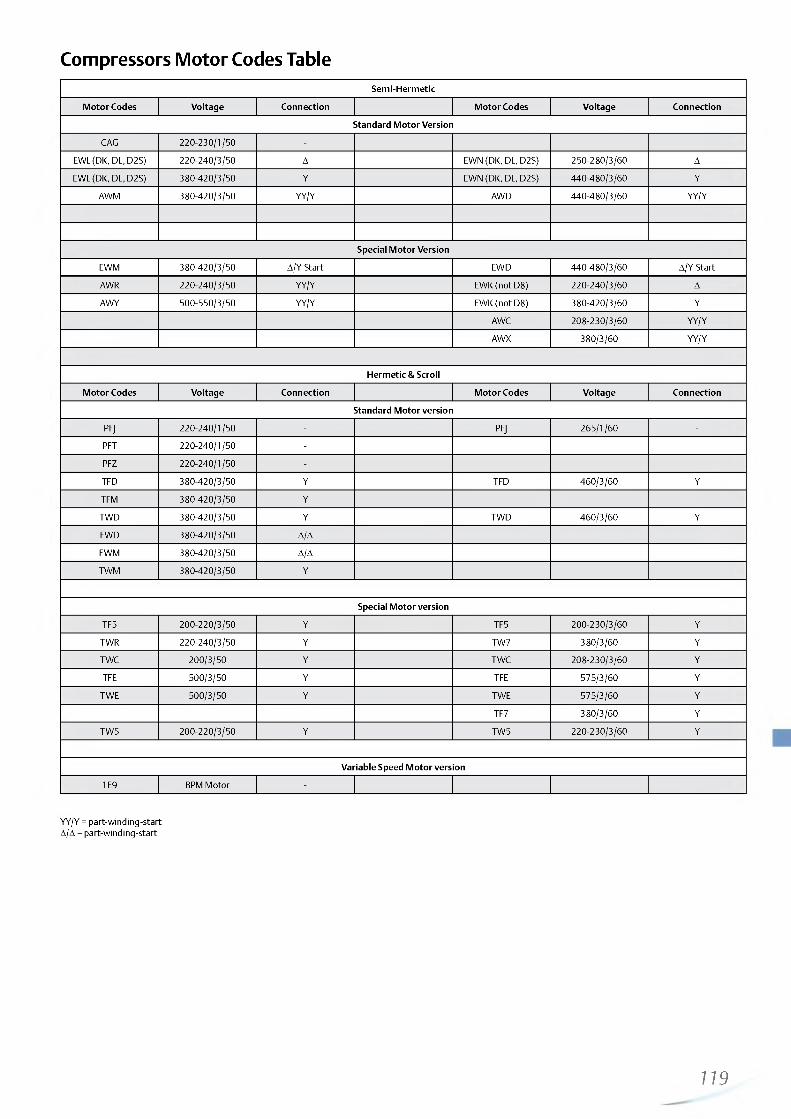
http://holodko.ru/
Compressors Motor Codes TableSemi-Hermetic
Motor Codes Voltage Connection Motor Codes Voltage Connection
Standard Motor Version
CAG 220-230/1/50 -
EWL (DK, DL, D2S) 220-240/3/50 A EWN (DK, DL, D2S) 250-280/3/60 A
EWL (DK, DL, D2S) 380-420/3/50 Y EWN (DK, DL, D2S) 440-480/3/60 Y
AWM 380-420/3/50 YY/Y AWD 440-480/3/60 YY/Y
Special Motor Version
EWM 380-420/3/50 A/Y-Start EWD 440-480/3/60 A/Y-Start
AWR 220-240/3/50 YY/Y EWK (not D8) 220-240/3/60 A
AWY 500-550/3/50 YY/Y EWK (not D8) 380-420/3/60 Y
AWC 208-230/3/60 YY/Y
AWX 380/3/60 YY/Y
Hermetic & Scroll
Motor Codes Voltage Connection Motor Codes Voltage Connection
Standard Motor version
PFJ 220-240/1/50 - PFJ 265/1/60 -
PFT 220-240/1/50 -
PFZ 220-240/1/50 -
TFD 380-420/3/50 Y TFD 460/3/60 Y
TFM 380-420/3/50 Y
TWD 380-420/3/50 Y TWD 460/3/60 Y
FWD 380-420/3/50 A/A
FWM 380-420/3/50 A/A
TWM 380-420/3/50 Y
Special Motor version
TF5 200-220/3/50 Y TF5 200-230/3/60 Y
TWR 220-240/3/50 Y TW7 380/3/60 Y
TWC 200/3/50 Y TWC 208-230/3/60 Y
TFE 500/3/50 Y TFE 575/3/60 Y
TWE 500/3/50 Y TWE 575/3/60 Y
TF7 380/3/60 Y
TW5 200-220/3/50 Y TW5 220-230/3/60 Y
Variable Speed Motor version
1E9 BPM Motor -
YY/Y = part-winding-start A/A = part-winding-start
119

http://holodko.ru/
Notes
120—

http://holodko.ru/
Notes
121

http://holodko.ru/

http://holodko.ru/
Alco Controls
Alco Controls is the leading provider of precision electronic
and electromechanical controls for the refrigeration and air
conditioning markets. We continue to pioneer the control
of refrigerant flow with innovative designs, keeping system
performance optimization central to our product development.
The wide range of Emerson controllers covers all major
applications in commercial air conditioning and refrigeration, as
well as heat pump systems. There are stand alone controllers and
controllers with a communication interface, which can be used in
LON networked systems too.
The controllers with TCP/IP Ethernet communication feature a
full web server function and provide full data exchange with any
user in the World Wide Web. This allows quick and inexpensive
monitoring from any PC with a standard web browser.
Emerson offers drivers and superheat controllers designed
for the EX4 to EX8 range of electrically driven control valves.
The superheat controllers allow stable superheat control with
the EX valves, while the digital superheat controllers can be
synchronized with the PWM capacity control valve incorporated
in the Digital Scroll™ compressor technology.
Display case and cold room controllers provide all functions
needed to run commercial refrigeration, like superheat control
with electrical control valve, thermostat, fan and defrost control,
integrated timer and alarm functions.
Other controllers offer control functions on the “hot side” of the
refrigeration circuit: condenser and condensing unit controllers,
rack controllers for up to 8 single stage compressors or for multi
stage compressors and dual circuit controllers.
The compressor soft starter allows keeping the starting current
below the limit imposed in residential heat pump applications.
Electronic fan speed controllers help to maintain a minimum
condensing pressure by reducing fan speed at low ambient
temperature.
Sensors and accessories are needed in conjunction with the
above mentioned controllers.
Oil management systems are used to maintain the oil level in the
compressor's crank case.
Em erson's controls portfolio is completed by offering a variety of
mechanical controls such as:
- pressostats & thermostats,
- system protectors,
- valves,
- thermo™-Expansion Valves,
- oil separators,
- and Suction Accumulators.
Whatever control you choose, you can always expect high
reliability and best performance.
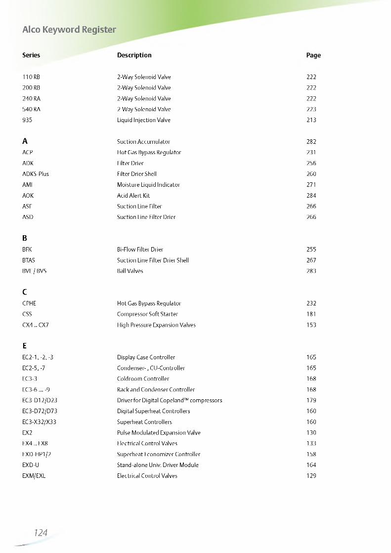
http://holodko.ru/
Alco Keyword Register
Series Description gaP110 RB 2-Way Solenoid Valve 222
200 RB 2-Way Solenoid Valve 222
240 RA 2-Way Solenoid Valve 222
540 RA 2-Way Solenoid Valve 223
935 Liquid Injection Valve 213
A Suction Accumulator 282
ACP Hot Gas Bypass Regulator 231
ADK Filter Drier 256
ADKS-Plus Filter Drier Shell 260
AMI Moisture Liquid Indicator 271
AOK Acid Alert Kit 284
ASF Suction Line Filter 266
ASD Suction Line Filter Drier 266
BBFK Bi-Flow Filter Drier 255
BTAS Suction Line Filter Drier Shell 267
BVE / BVS Ball Valves 283
CCPHE Hot Gas Bypass Regulator 232
CSS Compressor Soft Starter 181
CX4 .. CX7 High Pressure Expansion Valves 153
EEC2-1, -2, -3 Display Case Controller 1 65
EC2-5, -7 Condenser- , CU-Controller 1 65
EC3-3 Coldroom Controller 1 68
EC3-6 ... -9 Rack and Condenser Controller 168
EC3-D12/D23 Driver for Digital Copeland™ compressors 179
EC3-D72/D73 Digital Superheat Controllers 1 60
EC3-X32/X33 Superheat Controllers 1 60
EX2 Pulse Modulated Expansion Valve 130
EX4 .. EX8 Electrical Control Valves 133
EXD-HP1/2 Superheat Economizer Controller 158
EXD-U Stand-alone Univ. Driver Module 1 64
EXM/EXL Electrical Control Valves 129
—124

http://holodko.ru/
Alco Keyword Register
FFD 113 Differential Pressure Switch 247
FDB Filter Drier 258
FDH Filter Drier Shell 261
FDS-24 Filter Drier Shell 262
FSE Fan Speed Control Module 186
FSY Electronic Fan Speed Controller 184
L Liquid Injection Valve 186
MM36 3-Way Solenoid Valve 227
MIA Moisture Liquid Indicator 270
OOM3 / OM4 Oil Level Management System 275
OW4 Electronic Oil Level Monitoring 278
OS Oil Separator 279
PPRC Crankcase Pressure Regulator 235
PRE Evaporator Pressure Regulator 234
PS1 Pressure Controls 240
PS2 Dual Pressure Controls 242
PS3 Pressure Controls 244
PT5 Pressure Transmitter 182
T Thermo™-Expansion Valve 202
TI Thermo™ Expansion Valve 190
TS1 Thermostat 250
TX3 Thermo™ ExpansionValve 198
TX6 Thermo™ Expansion Valve 200
ZZZ Thermo™ -Expansion Valve 208
Series Description Page
125

http://holodko.ru/
126__—

http://holodko.ru/
Electrical Control Valves

http://holodko.ru/
Electrical Control Valves
Electrical Control Valve TechnologyTherm osta tic expansion valves and m echanical regulator valves have been used in the refrigeration and air conditioning industry to control superheat and refrigerant mass flow since its very beginning. As today's systems require improved energy efficiency, tighter temperature control, wider range of operating conditions and incorporate new features like remote monitoring and diagnostics, the application of electronically operated valves becomes mandatory. Only they offer the controls performance necessary to meet these needs. Electrical control valves are actuators only. For operation in a system they need sensors, valve drivers and controllers, see next chapter.
EXM/EXL biflow valves for OEM use are equipped with an unipolar stepper motor drive. They are mainly used for heat pumps, air conditioning and close control.
EX2 is designed for pulse width modulation. It is applicable to all common HCFC and HFC refrigerants and for subcritical CO2 applications and is used mainly for refrigeration applications such as display cases. The EX2 valve is a slide type solenoid valve with an orifice for expansion. It is either completely open or completely closed. One common valve body can be combined with6 interchangeable orifices to cover 7 capacity ranges.
EX4/EX5/EX6/EX7/EX8 consist of two main internal assemblies, the valve and the stepper motor. The stepper motor is located next to the electrical plug and connected directly to the slide and cage assembly of the valve. Similar to the technology used in compressors, the motor is exposed to refrigerant and lubricant and the materials used are identical to the ones in compressor
motors. The housing of the motor and valve assembly is made from stainless steel and fully hermetic, utilising exclusively brazing and welding technologies and eliminating all gaskets. This design offers several technical advantages such as proportional linear mass flow and a wide capacity range. A common feature of all EX2, EX4-8 electrical control valves is the positive shut-off function, which eliminates the need for additional solenoid valves.
CX4/CX5/CX6/CX7 High Pressure Expansion Valves are stepper motor driven valves for precise control of R744 (CO2) refrigerant mass flow in air conditioning, refrigeration and heat pump applications. The Control Valves also can be used for liquid injection duty and hot gas bypass.
Valve SelectionFor EX2 , the published table quotes capacities at 100% duty cycle. i.e., valve open continuously. However, it is recommended to operate the valve at partial load (50-80%) to allow for system load fluctuations. For EX4/EX5/EX6/EX7/EX8 and EXM/EXL , all published capacities are maximum and there are no reserve capacities. Each valve should be selected for the highest possible capacity of the system. A wide range regulation (10 ... 100%) with one slide orifice for each valve is achievable. To facilitate valve dimensioning for other than the standard conditions, Emerson Climate offers an Excel based Alco selection tool. This can be downloaded from www.emersonclimate.eu.
Selection Table for Electrical Control Valves and Applicable Controllers
Valvetype Function Capacity kW
R407C FeatureMin. Evaporating Temp.
°CMain Application Page Applicable Controller Page
EXMEXL
ExpansionValve 5 .. 20.7 Uni polar stepper
motor driven -30Heat pumps,
Air Conditioning, Close Control
129 EXD-HP1/2 s. data sheet
EX2 Exp. Valve 1.0 .. 18.7 PWM -40 Refrigeration 130 EC2 165
EX4EX5EX6
EX7EX8
ExpansionValve
2 .. 17 .4 5 .. 53
15 .. 126 35 .. 347 100 .. 925
Bi polar stepper motor driven
-50 Heat pumps, Refrigeration, A/C,
Water Chillers133
EC3-X .. Superheat Contr. EC3-3 .. Coldroom Contr.
160168
164- 1 0 0 EXD-U
EX4EX5EX6
EX7EX8
CapacityControl
4.91637131399
Bi polar stepper motor driven - 1 0 0
Hot gas bypass regulator 143 EXD-U .. Universal
Controls 164
EX6
EX7EX8
Liquid Mass Flow
Control
3.91442
Bi polar stepper motor driven -50
Suction pressure / Crankcase pressure
regulator144 EXD-U .. Universal
Controls 164
EX5EX6
EX7EX8
HeatReclaim
1843153463
Bi polar stepper motor driven -
Condensing pressure and liquid regulator 145 EXD-U .. Universal
Controls 164
EX6
EX7EX8
HeatReclaim
1 1
39119
Bi polar stepper motor driven -
Heat Reclaim applications 148 EXD-U .. Universal
Controls 164
CX4CX5CX6
CX7
ExpansionValve
Bi polar stepper motor driven -
Refrigeration CO2 transcritical
153 EXD-U .. Universal Controls 164
128

http://holodko.ru/
Electrical Control Valves Series EXM/EXLfor OEM use, stepper motor driven
FeaturesUnipolar stepper m otorBi-flow (sam e perform ance in both flow d irections in term of capacity)High M OPD: 40 bar in norm al flow direction Rem ovable coils in tw o versions: 12VD C/24VD C Continuous m odulation of m ass flow , no stress (liquid ham m ering) in the refrigeration circu it Linear flowResolution: 500 pulses (h a lf steps) or 250 full steps H erm etic designO nly Bulk packing in boxes o f 10 identical pieces Reliab ility: 225 m illions pulses at continuous 40 bar differential pressureThe valve is not released for refrigeration applications such as cold room s and refrigeration display cab inets.
EXM/EXL with Coil
Selection Chart
Type Part No. DescriptionNominal Capacity kW Connection
R410A R407C R134a size/style
EXM-B0A 8 0 0 399M Valve less coil 1.8 1.6 1.2EXM-B0B 80 0400M Valve less coil 5.5 5.0 3.7
1/4“ ODMEXM-B0D 80 0401M Valve less coil 11.6 10.5 7.7
EXM-B0E 80 0402M Valve less coil 13.7 12.4 9.1EXM-125 80 0403M Coil 12VDC, 5 wires - - -EXM-246 80 0404M Coil 24VDC, 6 wires - - -EXL-B1F 80 0405M Valve less coil 17.0 15.4 11.3 1/4“ ODFEXL-B1G 80 0406M Valve less coil 23.0 20.7 15.2 8 mm ODM
EXL-125 80 0407M Coil 12VDC, 5 wires - - -EXL-246 80 0408M Coil 24VDC, 6 wires - - -
The nominal capacity is based on the following conditions:
Refrigerant Evaporating temperature Condensing temperature Subcooling
R407C +4°C (dew point) +38°C bubble point / +43°C dew point 1K
R134a, R410a +4°C +38°C 1K
Technical DataMax. allowable pressure PS
45 bar
MOPD 40 bar in normal flow directionTemperature range TS TS: -30 to +70°C (liquid refrigerant)
-30 to +60°C (ambient)CE marking Not requiredWeight Valve EXM: 65 g, EXL: 76 g
Coil EXM: 124 g, EXL: 156 gPackage and delivery Bulk pack with 10 pieces
Stepper motor type Uni-polar, constant voltageFull travel time 16.6 seconds at 30 pulse/sec.
5.5 seconds at 90 pulse/secReference position Mechanical stop at fully close positionTotal number of pulses 500 half step (250 full step)Insulation class EXM: A
EXL: ECable length 1m
129
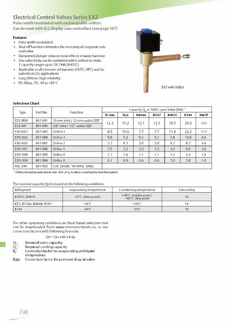
http://holodko.ru/
Electrical Control Valves Series EX2Pulse width modulated with exchangeable orifices Can be used with EC2 display case controllers (see page 167)
Features• Pulse width modulated• Shut off function eliminates the necessity of a separate sole
noid valve• Dampened plunger reduces noise effects of water hammer• One valve body can be combined with 6 orifices to make
7 capacity ranges up to 18.7 kW (R407C)• Applicable to all common refrigerants (HCFC, HFC) and for
subcritical CO2 applications• Long lifetime, high reliability• PS: 40bar, TS: -40 to +65°C
Selection Chart
Type Part No. FunctionCapacity Qn at 100% open Valve (kW) *
R 13 4a R22 R 4 0 4 A R 507 R 407C R 744 R407F
EX2-M00 801 091 10 mm inlet / 12 mm outlet ODF13.3 17.2 12.1 12.1 18.7 35.0 19.2
EX2-I00 801 090 3/8” inlet / 1/2” outlet ODF
EXO-004 801 089 Orifice 4 8.5 10.9 7.7 7.7 11.8 22.2 12.2
EXO-003 801 088 Orifice 3 5.6 7.2 5.1 5.1 7.8 14.6 8.0
EXO-002 801 087 Orifice 2 3.3 4.3 3.0 3.0 4.7 8.7 4.8
EXO-001 801 086 Orifice 1 2.5 3.2 2.3 2.3 3.5 6.5 3.6
EXO-000 801 085 Orifice 0 1.2 1.6 1.1 1.1 1.7 3.3 1.8
EXO-00X 801 084 Orifice X 0.7 0.9 0.6 0.6 1.0 1.8 1.0
ASC 24V 801 062 Coil 24 VAC 50-60Hz (8W)
* Orifice should be selected at max. 80% of Qn to allow covering the load fluctuation
The nominal capacity (Qn) is based on the following conditions:
Refrigerant Evaporating temperature Condensing temperature Subcooling
R407C, R407F +4°C (dew point) +38°C bubble point / +43°C dew point 1K
R22, R134a, R404A, R507 +4°C +38°C 1KR744 -40°C -10°C 1K
For other operating conditions an Excel based selection tool can be downloaded from w w w .em ersonclim ate .eu , or use correction factors w ith following form ula:
Qn = Qo x Kt x KAp
Q n: Nom inal valve capacityQo: Required cooling capacityKt: Correction facto r for evaporating and liquid
tem perature KAp: Correction facto r for pressure drop at valve
EX2 with Orifice
130—

http://holodko.ru/
LiquidTemperature entering Valve °C
R134aCorrection Factor Kt
Evaporating Tem perature °C
1 5 10 5 0 -5 -1 0 -1 5 -20 -2 5 -30 -40
55 1.21 1.23 1.26 1.29 1.33 1.33 1.39 1.43 1.47 1.52 1.62
50 1.13 1.15 1.17 1.20 1.23 1.26 1.28 1.32 1.36 1.39 1.48
45 1.06 1.08 1.10 1.12 1.15 1.17 1.19 1.22 1.26 1.29 1.37
40 0.99 1.01 1.03 1.05 1.08 1.10 1.12 1.14 1.17 1.20 1.27
35 0 .94 0 .96 0 .97 0.99 1.01 1.03 1.05 1.07 1.10 1.12 1.18
30 0.89 0.91 0 .92 0 .94 0 .96 0 .98 0 .99 1.01 1.03 1.06 1.11
25 0.85 0 .86 0 .87 0.89 0.91 0 .92 0 .94 0 .95 0.97 1.00 1.04
20 0.81 0 .82 0 .83 0.85 0 .89 0 .88 0 .89 0.91 0.92 0 .94 0 .98
15 0 .77 0 .78 0 .79 0.81 0 .82 0 .84 0 .84 0 .86 0.88 0 .89 0 .93
10 0.75 0 .76 0.77 0.78 0 .80 0.81 0 .82 0 .84 0 .85 0 .89
5 0.73 0 .74 0 .75 0 .76 0 .77 0.78 0.80 0.81 0 .84
0 0.71 0.72 0 .73 0 .74 0.75 0 .76 0 .78 0.81
-5 0 .69 0 .70 0.71 0.72 0.73 0 .74 0 .77
-10 0.68 0 .68 0.69 0.70 0.71 0 .74
Correction Factor KAp
Ap 3.5 4.0 4.5 5.0 5.5 6.0 6.5 7.0 7.5 8.0 8.5 9.0 10.0 11.0 12.0 13.0 14.0 15.0 16.0 17.0 18.0 19.0 20.0 21.0
KAp 1.34 1.25 1.18 1.12 1.07 1.02 0.98 0.95 0.91 0 .88 0 .86 0 .83 0 .79 0 .75 0 .72 0.69 0.67 0.65 0 .63 0.61 0 .59 0.57 0 .56 0 .55
LiquidTem perature entering Valve °C
R404ACorrection Factor Kt
Evaporating Tem perature °C
15 10 5 0 -5 -1 0 -1 5 -20 -2 5 -30 -3 5 -40
55 1.42 1.46 1.50 1.55 1.61 1.68 1.75 1.83 1.92 2.01 2.13 2.25
50 1.23 1.26 1.30 1.34 1.38 1.43 1.48 1.54 1.61 1.68 1.75 1.84
45 1.10 1.12 1.15 1.18 1.22 1.26 1.30 1.34 1.39 1.45 1.51 1.57
40 0.99 1.02 1.04 1.07 1.09 1.13 1.16 1.20 1.24 1.28 1.33 1.38
35 0.91 0 .93 0 .95 0.97 1.00 1.02 1.05 1.08 1.11 1.15 1.19 1.23
30 0 .84 0 .86 0 .88 0.90 0.92 0 .94 0 .96 0 .99 1.02 1.05 1.08 1.11
25 0.79 0 .80 0 .82 0.83 0 .85 0 .87 0 .89 0 .92 0 .94 0 .97 0 .99 1.02
20 0 .74 0 .75 0 .77 0.78 0 .80 0.81 0 .83 0 .85 0.87 0 .90 0 .92 0 .95
15 0.70 0.71 0 .72 0.73 0 .75 0 .76 0 .78 0 .80 0.82 0 .84 0 .86 0 .88
10 0.67 0 .68 0.69 0.71 0 .72 0 .74 0 .75 0.77 0 .79 0.81 0 .83
5 0.65 0 .66 0.67 0 .68 0 .70 0.71 0.73 0 .74 0 .76 0 .78
0 0.63 0 .64 0 .65 0 .66 0.68 0.69 0.71 0 .72 0 .74
-5 0.61 0 .62 0 .63 0.65 0 .66 0 .67 0 .69 0 .70
-10 0.60 0.61 0 .62 0 .63 0 .64 0 .65 0.67
Correction Factor KAp
Ap 3.5 4.0 4.5 5.0 5.5 6.0 6.5 7.0 7.5 8.0 8.5 9.0 10.0 11.0 12.0 13.0 14.0 15.0 16.0 17.0 18.0 19.0 20.0 21.0
KAp 1.74 1.63 1.54 1.46 1.39 1.33 1.28 1.23 1.19 1.15 1.12 1.09 1.03 0 .98 0 .94 0.9 0 .87 0 .84 0.81 0.79 0.77 0.75 0 .73 0.71
LiquidTemperature entering Valve °C
R744Correction Factor Kt
Evaporating Tem perature °C
5 0 -5 -10 -1 5 -20 -2 5 -30 -35 -40
5 1.12 1.10 1.09 1.08 1.08 1.08 1.07 1.07 1.08 1.08
0 1.02 1.01 1.01 1.00 1.00 1.00 1.00 1.00 1.01
-5 0 .95 0 .94 0 .94 0 .94 0 .94 0 .94 0 .94 0 .94
-10 0.89 0.89 0 .88 0 .88 0 .88 0.89 0.89
-15 0.84 0 .84 0 .84 0 .84 0 .84 0 .84
-20 0.80 0 .80 0 .80 0.80 0 .80
-25 0 .76 0 .76 0 .76 0 .76
-30 0.73 0.73 0 .73
-35 0.70 0 .70
-40 0.67
Correction Factor KAp
Ap 5.0 6.0 7.0 8.0 9.0 10.0 11.0 12.0 13.0 14.0 15.0 16.0 17.0 18.0 19.0 20.0 21.0 22.0 23.0 24.0 25.0 26.0 27.0 28.0
KAp 1.81 1.65 1.53 1.43 1.35 1.28 1.22 1.17 1.12 1.08 1.05 1.01 0 .98 0 .95 0 .93 0.91 0.88 0 .86 0 .84 0 .83 0.81 0 .79 0 .78 0 .77
131

http://holodko.ru/
LiquidTemperature entering Valve °C
R22Correction Factor Kt
Evaporating Temperature °C
15 10 5 0 -5 -10 -15 -20 -25 -30 -35 -40
55 1.17 1.19 1.20 1.22 1.24 1.25 1.27 1..29 1.32 1.34 1.37 1.39
50 1.11 1.11 1.13 1.15 1.16 1.18 1.20 1.22 1.24 1.26 1.28 1.30
45 1.05 1.05 1.07 1.08 1.10 1.12 1.13 1.15 1.17 1.18 1.20 1.23
40 1.00 1.01 1.02 1.03 1.04 1.06 1.07 1.09 1.10 1.12 1.14 1.16
35 0.95 0.96 0.97 0.98 0.99 1.01 1.02 1.03 1.05 1.06 1.08 1.10
30 0.91 0.92 0.93 0.94 0.95 0.96 0.97 0.98 1.00 1.01 1.03 1.04
25 0.87 0.88 0.89 0.89 0.91 0.92 0.93 0.94 0.95 0.96 0.98 0.99
20 0.83 0.84 0.85 0.86 0..87 0.88 0.89 0.90 0.91 0.92 0.93 0.95
15 0.80 0.81 0.81 0.82 0.83 0.84 0.85 0.86 0.87 0.88 0.89 0.91
10 0.78 0.78 0.79 0.80 0.81 0.82 0.83 0.84 0.85 0.86 0.87
5 0.75 0.76 0.77 0.78 0.79 0.79 0.80 0.81 0.82 0.83
0 0.73 0.74 0.75 0.76 0.77 0.77 0.78 0.79 0.80
-5 0.72 0.72 0.73 0.74 0.75 0.75 0.76 0.77
-10 0.70 0.71 0.71 0.72 0.73 0.74 0.74
Correction Factor KAp
Ap 3.5 4.0 4.5 5.0 5.5 6.0 6.5 7.0 7.5 8.0 8.5 9.0 10.0 11.0 12.0 13.0 14.0 15.0 16.0 17.0 18.0 19.0 20.0 21.0
KAp 1.59 1.49 1.40 1.33 1.27 1.22 1.17 1.13 1.09 1.05 1.02 0.99 0.94 0.90 0.86 0.83 0.80 0.77 0.75 0.72 0.70 0.68 0.67 0.65
LiquidTemperature entering Valve °C
R507Correction Factor Kt
Evaporating Temperature °C
15 10 5 0 -5 -10 -15 -20 -25 -30 -35 -40
55 1.39 1.43 1.47 1.52 1.57 1.62 1.69 1.76 1.83 1.92 2.02 2.12
50 1.22 1.24 1.28 1.31 1.35 1.40 1.44 1.49 1.55 1.61 1.68 1.76
45 1.09 1.11 1.14 1.17 1.20 1.23 1.27 1.31 1.36 1.40 1.46 1.52
40 0.99 1.01 1.03 1.06 1.08 1.11 1.14 1.17 1.21 1.25 1.29 1.34
35 0.91 0.93 0.95 0.97 0.99 1.01 1.04 1.07 1.10 1.13 1.16 1.20
30 0.85 0.86 0.88 0.89 0.91 0.93 0.96 0.98 1.01 1.03 1.06 1.09
25 0.79 0.80 0.82 0.83 0.85 0.87 0.89 0.91 0.93 0.95 0.98 1.01
20 0.74 0.75 0.77 0.78 0.79 0.81 0.83 0.85 0.87 0.89 0.91 0.93
15 0.71 0.71 0.72 0.73 0.75 0.76 0.78 0.79 0.81 0.83 0.85 0.87
10 0.67 0.68 0.69 0.70 0.72 0.73 0.74 0.76 0.78 0.79 0.81
5 0.64 0.65 0.67 0.68 0.69 0.70 0.72 0.73 0.75 0.76
0 0.62 0.63 0.64 0.65 0.66 0.68 0.69 0.70 0.72
-5 0.60 0.61 0.62 0.63 0.64 0.65 0.66 0.68
-10 0.58 0.59 0.60 0.61 0.62 0.63 0.64
Correction Factor KAp
Ap 3.5 4.0 4.5 5.0 5.5 6.0 6.5 7.0 7.5 8.0 8.5 9.0 10.0 11.0 12.0 13.0 14.0 15.0 16.0 17.0 18.0 19.0 20.0 21.0
KAp 1.75 1.64 1.54 1.46 1.4 1.34 1.28 1.24 1.19 1.16 1.12 1.09 1.03 0.99 0.94 0.91 0.87 0.84 0.82 0.79 0.77 0.75 0.73 0.71
LiquidTemperature entering Valve °C
R407CCorrection Factor Kt
Evaporating Temperature °C
15 10 5 0 -5 -10 -15 -20 -25
55 1.26 1.28 1.31 1.34 1.37 1.40 1.44 1.48 1.52
50 1.15 1.17 1.19 1.22 1.24 1.27 1.30 1.33 1.37
45 1.06 1.08 1.10 1.12 1.14 1.17 1.19 1.22 1.25
40 0.99 1.01 1.02 1.04 1.06 1.08 1.11 1.13 1.16
35 0.93 0.94 0.96 0.98 0.99 1.01 1.03 1.05 1.07
30 0.88 0.89 0.90 0.92 0.93 0.95 0.97 0.99 1.01
25 0.83 0.84 0.85 0.87 0.88 0.90 0.91 0.93 0.95
20 0.79 0.80 0.81 0.82 0.84 0.85 0.86 0.88 0.90
15 0.75 0.76 0.77 0.78 0.80 0.81 0.82 0.84 0.85
10 0.73 0.74 0.75 0.76 0.77 0.78 0.80 0.81
5 0.71 0.72 0.73 0.74 0.75 0.76 0.77
0 0.69 0.70 0.71 0.72 0.73 0.74
-5 0.67 0.68 0.69 0.70 0.71
-10 0.65 0.66 0.67 0.68
Correction Factor KAp
Ap 3.5 4.0 4.5 5.0 5.5 6.0 6.5 7.0 7.5 8.0 8.5 9.0 10.0 11.0 12.0 13.0 14.0 15.0 16.0 17.0 18.0 19.0 20.0 21.0
KAp 1.81 1.69 1.59 1.51 1.44 1.38 1.33 1.28 1.23 1.19 1.16 1.13 1.07 1.02 0.98 0.94 0.9 0.87 0.84 0.82 0.8 0.78 0.76 0.74
132—

http://holodko.ru/
Electrical Control Valves Series EX4, EX5, EX6, EX7 & EX8
Features• M ultifunction as expansion valve , hot gas bypass,
suction gas th ro ttling , head pressure, liquid level actuator etc.
• Fully herm etic design (no thread jo in ts betw een valve body and m otor com partm ent)
• Applicab le to all com m on refrigerants (H CFC ,HFC) and for subcritical CO2 applications
• Stepper m otor driven• Short opening and closing tim e• V ery fast full stroke tim e• High resolution and excellent repeatab ility• Positive shut-off function to elim inate use of
additional solenoid valve• Bi-flow versions for heat pum p applications• High linear flow capacity• Extrem ely w ide capacity range (10 ... 100%)• Continuous m odulation of mass flow , no stress
(liquid ham m ering) in the refrigeration c ircu it• D irect coupling of m otor and valve for high
reliab ility (no gear m echan ism )• Ceram ic slide and port for h ighly accurate flow
and m inim al w ear• Europe patent No. 07 4 3 4 7 6 , USA patent
No. 57 3550 1 , Japan patent No. 28225789• Balanced force design• Corrosion resistant sta in less steel body and stain less
steel connections• PS: EX4-EX7 60 bar, EX 8 45 bar• Liquid Inlet Tem perature TS:
Uniflow : -50 to +100°C, B iflow : -40 to +80°C
Selection Chart (Capacities see following pages)
Type Part No. Flow Pattern Capacity Range Inlet Connection Outlet Connection Electrical Connection
EX4-I21 800 615 3/8“ ODF 5/8“ ODFEX4-M21 800 616 10mm ODF 16mm ODFEX5-U21 800618 5/8“ (16mm) ODF 7/8“ (22mm) ODFEX6-I21 800 620 7/8“ ODF 1-1/8“ ODFEX6-M21 800621
Uni-flow22mm ODF 28 mm ODF
EX7-I21 800 624 1-1/8“ ODF 1-3/8“ ODFEX7-M21 800 625 28mm ODF 35mm ODFEX8-M21 800 629 10 ... 100% 42mm ODF 42mm ODF M12 Plug
EX8-U21 800 630 1-3/8“ (35mm) ODF 1-3/8“ (35mm) ODFEX8-I21 800 631 1-5/8” ODF 1-5/8” ODFEX4-U31 800 617 5/8“ (16mm) ODF 5/8“ (16mm) ODFEX5-U31 800 619
Bi-flow (Heat Pump)
7/8“ (16mm) ODF 7/8“ (22mm) ODFEX6-I31 800 622 1-1/8“ ODF 1-1/8“ ODFEX6-M31 800 623 28mm ODF 28mm ODFEX7-U31 800626 1-3/8“ (35mm) ODF 1-3/8“ (35mm) ODF
Type Part No. Temperature Range Length Connector type to valve Connector type to driver or controller Illustration
EXV-M15 804 663-50 ... +80°C
1.5 mM12, 4 pins Loose wires " DEXV-M30 804 664 3.0 m
EXV-M60 804 665 6.0 m
133

http://holodko.ru/
Capacity Data
Application Expansion Valve and Liquid Injection Valve - Nominal Capacity kW
Valve Type R 407C R22 R 13 4a R 4 0 4 A R 4 1 0 A R 23 * R 12 4 * R 744 R 40 7F
EX 4 2 .. 17.4 2 . 16.5 1 .. 12.8 1 .. 11.5 2 .. 19.3 2 .. 17.8 1 .. 9.2 3 . 33.5 18
EX 5 5 . 53 5 .. 50 4 .. 39 4 .. 35 6 . 58 5 .. 54 3 .. 28 10 . 102 56E X 6 15 . 126 15 .. 120 10 .. 93 10 .. 84 15 . 140 13 .. 130 7 .. 67 24 . 244 134EX 7 35 . 347 35 .. 330 25 .. 255 25 .. 230 40 . 385 - - 70 . 670 369E X 8 100 .. 925 90 .. 880 70 .. 680 60 .. 613 100 . 1027 - - 180 . 1789 984
* Biflow versions are not released for R124 and R23Capacity for biflow versions identical in both flow directions.
The nominal capacity (Qn) is based on the following conditions:
Refrigerant Evaporating temperature Condensing temperature Subcooling
R407C, R407F +4°C (dew point) +38°C bubble point / +43°C dew point 1K
R22, R134a, R404A, R410A +4°C +38°C 1KR124 +20°C +80°C 1KR23 -60°C -25°C 1KR744 -40°C -10°C 1K
Guideline for Selection of Electrical Control Valves as Expansion Valves
Alco Selection ToolFor easy and quick selection of Electrical Control Valves an Excel based selection tool can be downloaded from the Internet at www.emersonclimate.eu, or use the quick selection tables on the following pages.
The following guideline should be taken into consideration in order to obtain full advantages of the control valves:
- Published capacities are maximum and there are no reserve capacities
- Larger size of valve leads to shorter pull down period and shorter travel tim e i.e ., faster response. For exam ple,EX7 has maximum 3.2 seconds travel time. The valve has approxim ately 1.6 seconds travel tim e at 50% capacity operation.
For controllers, see page 152, 153 and 157.
Example:System with R407C having two different operating conditions:A) 110 kW capacity at +4°C/+50°C with two stages
compressor at 50% / 100% capacityB) 137 kW capacity at +4°C/+30°C with two stages
compressor at 50% / 100% capacityEX6 with 126 kW covers condition A, however is not sufficient to cover condition B. It is recommended to select larger valve i. e. EX7 with 337 kW at condition A and 293 kW at condition B.
Condition A:
Full load ratio = 110 / 337 = 33%
Partial load ratio = (110/2) / 337 = 16%
Condition B:
Full load ratio = 137 / 293 = 47%
Partial load ratio = (137/2) / 293 = 23%
The capacity ratios of system to valve are in all conditions higher than 10%. It is recommended to use EX7 rather than EX6 .
134—

http://holodko.ru/
Application Expansion Valve and Liquid Injection Valve
CondensingTemperature
°C
R134a Extended capacity (kW ) Evaporating Tem perature (°C) Valve
Type1 5 10 5 0 -5 -1 0 -1 5 -20 -2 5 -30 -3 5 -40 -45
13 13 13 13 13 13 12 12 12 12 11 11 11 EX4
39 39 39 39 39 39 38 37 36 35 34 33 32 EX5
60 93 94 94 94 93 92 90 89 87 84 82 79 77 EX6
255 257 258 257 255 252 248 243 237 231 224 217 210 EX7
679 686 688 686 680 672 661 648 633 616 598 580 560 EX8
12 13 13 13 13 13 13 12 12 12 12 11 11 EX4
38 39 39 39 39 39 38 38 37 36 35 34 33 EX5
55 91 92 93 94 93 93 92 90 88 86 84 82 80 EX6
249 253 256 257 256 254 251 247 242 237 231 225 218 EX7
663 676 683 685 683 678 670 659 647 632 616 599 582 EX8
12 12 13 13 13 13 13 12 12 12 12 12 11 EX4
36 38 38 39 39 39 38 38 37 37 36 35 34 EX5
50 87 90 91 92 93 92 92 91 89 88 86 84 81 EX6
238 246 250 253 254 253 251 249 245 240 235 229 223 EX7
636 655 668 675 677 676 671 663 653 640 627 611 595 EX8
11 12 12 12 12 13 12 12 12 12 12 12 11 EX4
34 36 37 38 38 38 38 38 37 37 36 35 35 EX5
45 81 85 88 90 91 91 91 90 89 88 86 84 82 EX6
223 234 241 246 248 249 249 247 244 240 236 231 226 EX7
595 623 642 655 662 664 663 658 651 641 629 616 602 EX8
10 11 11 12 12 12 12 12 12 12 12 12 11 EX4
31 33 35 36 37 37 37 37 37 36 36 35 34 EX5
40 74 79 83 85 87 88 89 88 88 87 85 84 82 EX6
202 217 227 234 239 242 243 242 240 238 234 230 225 EX7
539 578 606 625 638 645 647 646 641 634 625 614 601 EX8
9 10 10 11 11 12 12 12 12 12 12 11 11 EX4
27 30 32 34 35 35 36 36 36 36 35 35 34 EX5
35 63 71 76 80 83 84 85 86 85 85 84 83 81 EX6
173 194 209 219 226 231 234 235 234 232 230 227 223 EX7
463 517 556 584 604 616 623 625 624 620 613 604 594 EX8
7 8 9 10 11 11 11 11 11 11 11 11 11 EX4
20 25 28 30 32 33 34 34 34 34 34 34 33 EX5
30 49 60 67 73 76 79 81 82 82 82 81 80 79 EX6
133 164 184 199 210 217 221 224 225 224 223 221 217 EX7
356 436 492 534 559 578 590 597 600 599 595 588 580 EX8
3 6 8 9 9 10 10 11 11 11 11 11 11 EX4
10 18 23 26 29 30 31 32 33 33 33 32 32 EX5
25 23 121 152 137 188 198 206 210 213 214 213 212 210 EX6
63 121 152 173 188 198 206 210 213 214 213 212 210 EX7
169 322 406 462 501 529 548 560 567 570 569 565 559 EX8
2 5 7 8 9 9 10 10 10 10 10 10 EX4
5 16 21 25 27 28 29 30 31 31 31 31 EX5
20 12 38 51 58 64 68 70 72 73 73 73 73 EX6
34 105 139 160 175 186 193 197 200 201 201 199 EX7
90 281 370 427 467 495 514 526 533 536 535 532 EX8
4 6 7 8 9 9 9 9 9 9 EX4
13 19 22 25 26 27 28 28 29 29 EX5
15 32 45 53 59 62 65 67 68 68 68 EX6
87 123 145 161 171 178 183 186 187 187 EX7
231 328 388 428 456 475 488 495 498 498 EX8
3 5 6 7 8 8 8 9 9 EX4
9 16 20 22 24 25 26 26 26 EX5
10 22 38 47 52 56 59 61 62 62 EX6
61 104 128 144 155 162 167 170 171 EX7
162 277 341 384 413 432 445 452 455 EX8
135

http://holodko.ru/
Application Expansion Valve and Liquid Injection Valve
CondensingTemperature
°C
R22 Extended capacity (kW ) Evaporating Tem perature (°C) Valve
Type15 10 5 0 -5 -1 0 -1 5 -20 -2 5 -30 -3 5 -40 -45
17 17 18 18 18 18 18 18 18 17 17 17 17 EX4
51 52 53 54 54 54 54 54 53 53 52 52 51 EX5
60 123 126 128 129 130 130 130 129 128 127 126 124 122 EX6
337 345 351 355 357 358 357 356 353 350 345 340 335 EX7
900 921 936 946 952 954 953 948 941 932 921 908 893 EX8
16 17 17 18 18 18 18 18 18 18 17 17 17 EX4
50 51 52 53 54 54 54 54 54 53 53 52 52 EX5
55 119 123 126 128 129 130 130 130 129 128 127 126 124 EX6
328 339 346 352 355 357 358 357 356 353 350 345 340 EX7
876 903 923 938 948 953 955 953 949 941 932 921 908 EX8
16 16 17 17 18 18 18 18 18 18 18 17 17 EX4
48 50 51 52 53 54 54 54 54 54 53 53 52 EX5
50 114 119 123 125 127 129 129 129 129 128 127 126 125 EX6
314 327 337 345 350 354 355 356 355 353 351 347 343 EX7
838 873 899 919 933 943 948 949 947 942 935 925 914 EX8
15 16 16 17 17 17 17 18 18 18 17 17 17 EX4
45 47 49 51 52 52 53 53 53 53 53 52 52 EX5
45 107 113 118 121 124 126 127 128 128 127 127 126 124 EX6
295 311 324 334 341 346 349 351 351 350 348 346 342 EX7
787 830 864 890 909 923 932 936 937 934 929 922 912 EX8
13 15 15 16 16 17 17 17 17 17 17 17 17 EX4
41 44 46 48 50 51 52 52 52 52 52 52 51 EX5
40 98 106 111 116 119 122 124 125 125 125 125 124 123 EX6
270 290 306 319 328 335 340 343 345 345 344 342 339 EX7
719 774 817 850 875 894 907 915 919 919 916 911 903 EX8
12 13 14 15 16 16 16 17 17 17 17 17 17 EX4
36 40 43 45 47 49 50 50 51 51 51 51 50 EX5
35 86 96 103 109 113 117 119 121 122 122 122 122 121 EX6
237 264 284 300 312 321 327 332 335 336 336 335 333 EX7
632 703 757 799 831 856 873 885 893 896 896 893 888 EX8
10 11 13 14 15 15 16 16 16 16 16 16 16 EX4
29 35 39 42 44 46 47 48 49 49 49 49 49 EX5
30 70 83 93 100 106 110 113 116 117 118 118 118 118 EX6
194 229 256 276 291 303 312 318 322 325 326 326 324 EX7
516 611 682 735 776 808 831 848 859 866 869 868 865 EX8
7 9 11 12 13 14 15 15 15 16 16 16 16 EX4
20 28 33 37 40 43 44 46 46 47 47 48 48 EX5
25 47 67 80 90 97 102 106 109 112 113 114 114 114 EX6
130 184 220 246 266 281 292 301 307 311 313 314 314 EX7
347 491 587 656 709 749 779 802 818 829 835 837 836 EX8
6 9 10 12 13 13 14 14 15 15 15 15 EX4
18 26 32 36 39 41 42 44 45 45 45 46 EX5
20 43 63 76 85 93 98 102 105 107 108 109 109 EX6
117 173 209 235 254 269 280 288 294 298 300 300 EX7
312 461 557 627 678 718 747 768 784 793 799 801 EX8
5 8 10 11 12 13 13 14 14 14 14 EX4
15 24 30 34 37 39 40 42 42 43 43 EX5
15 37 58 71 81 88 93 97 100 102 103 104 EX6
101 160 196 222 241 256 266 274 279 283 285 EX7
269 426 524 593 644 682 710 731 745 754 759 EX8
4 7 9 10 11 12 13 13 13 13 EX4
12 22 28 31 34 36 38 39 40 40 EX5
10 29 53 66 76 82 87 91 94 96 97 EX6
80 145 182 208 227 241 251 258 263 267 EX7
214 386 485 554 604 642 669 689 702 711 EX8
136—

http://holodko.ru/
Application Expansion Valve and Liquid Injection Valve
CondensingTem perature
°C
R404A / R507 Extended capacity (kW ) Evaporating Tem perature (°C) Valve
Type15 10 5 0 -5 -1 0 -1 5 -20 -2 5 -30 -3 5 -40 -45
9 9 9 9 9 9 9 8 8 8 7 7 6 EX4
28 28 28 28 28 27 26 25 24 23 22 21 20 EX5
60 68 68 68 67 66 65 63 61 58 56 33 50 47 EX6
186 187 186 184 181 177 172 166 160 153 145 137 129 EX7
495 498 496 491 482 471 458 443 425 407 387 366 344 EX8
10 10 10 10 10 10 10 9 9 9 8 8 8 EX4
30 31 31 31 30 30 29 29 28 27 26 25 23 EX5
55 72 73 74 74 73 72 70 69 67 64 62 59 56 EX6
198 201 202 202 200 197 193 188 182 176 169 162 154 EX7
527 535 538 537 533 525 514 501 486 470 451 432 411 EX8
10 10 11 11 11 11 10 10 10 10 9 9 9 EX4
31 32 32 32 32 32 32 31 30 30 29 28 27 EX5
50 74 76 77 78 78 77 76 75 73 71 69 66 64 EX6
203 208 211 213 219 211 208 204 200 194 188 181 174 EX7
541 555 564 567 567 562 555 545 532 518 501 484 465 EX8
10 10 11 11 11 11 11 11 11 10 10 10 9 EX4
31 32 33 33 33 33 33 33 32 32 31 30 29 EX5
45 74 77 79 80 80 80 80 79 78 76 74 72 69 EX6
201 210 215 219 220 220 219 216 212 208 202 196 190 EX7
537 559 574 583 587 586 582 575 566 553 539 524 506 EX8
10 10 11 11 11 11 11 11 11 11 11 10 10 EX4
29 31 33 33 34 34 34 34 34 33 32 32 31 EX5
40 71 75 78 80 81 82 82 81 81 79 78 76 74 EX6
193 205 214 219 223 225 225 223 221 217 213 208 202 EX7
515 547 570 585 594 598 598 595 588 578 567 553 538 EX8
9 10 10 11 11 11 11 11 11 11 11 11 11 EX4
27 30 31 33 34 34 34 34 34 34 33 33 32 EX5
35 65 71 75 79 81 82 83 83 82 81 80 79 77 EX6
178 195 207 215 221 225 226 226 225 223 219 215 210 EX7
474 519 551 574 590 599 603 604 600 594 585 573 560 EX8
8 9 10 10 11 11 11 11 11 11 11 11 11 EX4
23 27 30 31 33 34 34 34 34 34 34 33 33 EX5
30 56 65 71 75 78 81 82 83 83 82 81 80 79 EX6
153 177 194 206 215 221 224 226 226 225 223 219 215 EX7
409 472 517 550 573 588 598 603 603 600 593 584 573 EX8
6 8 9 10 10 11 11 11 11 11 11 11 11 EX4
17 23 27 29 31 32 33 34 34 34 34 34 33 EX5
25 42 55 64 70 74 78 80 81 82 82 81 80 79 EX6
114 150 174 191 204 213 218 222 224 224 223 220 217 EX7
305 400 465 510 543 566 582 592 596 597 593 587 579 EX8
1 5 7 8 9 10 10 11 11 11 11 11 11 EX4
3 16 22 26 28 30 32 33 33 33 33 33 33 EX5
20 8 40 53 62 68 73 76 78 80 80 80 80 79 EX6
21 108 146 170 187 200 208 214 218 219 220 218 216 EX7
56 289 388 453 499 532 555 571 580 585 585 582 576 EX8
5 7 8 9 10 10 10 11 11 11 11 EX4
15 21 25 28 29 31 32 32 32 33 32 EX5
15 37 51 60 66 71 74 76 77 78 78 78 EX6
101 139 164 181 194 202 208 212 213 214 213 EX7
268 371 437 484 516 540 555 564 569 569 566 EX8
5 7 8 9 9 10 10 10 10 10 EX4
14 20 24 26 28 30 31 31 31 31 EX5
10 33 48 57 64 68 71 73 75 75 75 EX6
91 131 156 174 186 195 201 204 206 206 EX7
242 350 417 464 496 519 535 544 548 549 EX8
137

http://holodko.ru/
Application Expansion Valve and Liquid Injection Valve
Condensing Dew Point
°C
Tem perature Bubble
Point°C
R407C Extended capacity (kW ) Evaporating Tem perature (°C) Valve
Type15 10 5 0 -5 -1 0 -1 5 -20 -2 5 -30 -35 -40 -45
16 17 17 17 17 17 16 16 16 15 15 15 14 EX4
50 51 51 51 51 50 50 49 48 47 46 45 43 EX5
64 60 119 120 121 121 121 119 118 116 114 112 109 106 103 EX6
328 332 333 333 332 329 325 320 314 308 301 293 285 EX7
874 884 889 889 885 877 867 854 838 821 802 781 759 EX8
17 17 17 17 17 17 17 17 16 16 16 15 15 EX4
50 51 52 52 52 52 51 51 50 49 48 47 46 EX5
59 55 120 122 123 124 124 123 122 121 119 117 114 112 109 EX6
330 336 339 341 341 339 336 332 328 322 315 308 301 EX7
879 895 904 909 908 904 897 886 873 858 840 821 801 EX8
16 17 17 17 17 17 17 17 17 17 16 16 16 EX4
50 51 52 52 53 53 52 52 51 51 50 49 48 EX5
54 50 118 121 123 125 125 125 125 123 122 120 118 116 113 EX6
326 334 340 343 345 345 343 340 336 331 325 319 312 EX7
869 891 906 915 919 919 914 907 896 883 868 851 832 EX8
16 16 17 17 17 17 17 17 17 17 17 16 16 EX4
48 50 51 52 53 53 53 52 52 51 51 50 49 EX5
50 45 115 119 122 124 125 125 125 125 124 122 120 118 116 EX6
316 327 336 341 344 346 345 344 341 337 332 326 320 EX7
843 873 894 909 918 921 920 916 908 897 884 869 853 EX8
15 16 16 17 17 17 17 17 17 17 17 17 16 EX4
46 48 50 51 52 52 52 52 52 52 51 50 49 EX5
45 40 109 114 118 121 123 124 125 125 124 123 121 120 118 EX6
300 315 326 334 339 342 344 343 341 338 334 330 324 EX7
801 840 870 891 905 913 916 915 910 902 891 878 864 EX8
14 15 16 16 17 17 17 17 17 17 17 17 16 EX4
42 45 48 49 50 51 52 52 52 51 51 50 50 EX5
40 35 101 108 113 117 120 122 123 123 123 122 121 120 118 EX6
278 297 312 323 330 335 338 339 338 337 334 330 325 EX7
742 793 832 860 880 894 901 904 902 897 889 879 866 EX8
12 14 15 15 16 16 16 17 17 17 17 16 16 EX4
38 42 45 47 48 49 50 51 51 51 50 50 49 EX5
35 30 90 99 106 111 115 118 119 120 121 120 120 119 117 EX6
248 273 292 306 317 324 329 331 332 331 329 326 323 EX7
661 729 779 817 844 864 876 883 885 884 878 870 860 EX8
10 12 13 14 15 15 16 16 16 16 16 16 16 EX4
32 37 41 44 46 47 48 49 49 49 49 49 48 EX5
30 25 75 88 97 103 108 112 115 116 117 117 117 116 115 EX6
207 241 266 285 299 309 316 320 322 323 322 320 317 EX7
552 644 710 760 796 823 841 853 860 861 859 854 846 EX8
7 10 12 13 14 14 15 15 16 16 16 16 15 EX4
23 30 36 39 42 44 46 47 47 48 48 48 47 EX5
26 20 54 72 85 94 100 105 108 111 112 113 113 113 112 EX6
148 199 233 258 276 289 299 305 309 312 312 311 309 EX7
395 530 621 687 735 770 796 814 825 831 832 829 824 EX8
7 9 11 12 13 14 14 15 15 15 15 15 EX4
21 29 34 38 40 42 44 45 45 46 46 46 EX5
21 15 50 69 81 90 96 101 104 106 108 108 108 108 EX6
137 189 223 247 265 277 287 293 297 299 299 298 EX7
365 503 594 658 705 740 764 781 791 796 796 795 EX8
6 9 11 12 13 13 14 14 14 14 14 EX4
19 27 32 36 38 40 42 43 43 43 43 EX5
16 10 45 64 76 85 91 96 99 101 103 103 103 EX6
123 176 210 234 251 264 273 279 282 282 284 EX7
329 470 561 624 670 704 727 743 753 753 758 EX8
138

http://holodko.ru/
Application Expansion Valve and Liquid Injection Valve
CondensingTemperature
°C
R410A Extended capacity (kW ) Evaporating Tem perature (°C) Valve
Type1 5 10 5 0 -5 -1 0 -1 5 -20 18 -30 -3 5 -40 -45
17 17 18 18 18 18 18 18 18 18 17 17 17 EX4
51 52 53 54 54 54 54 54 53 53 52 51 50 EX5
60 123 126 129 130 131 131 131 130 129 127 125 123 120 EX6
339 348 354 358 360 361 360 358 354 350 344 338 331 EX7
EX8
18 18 19 19 19 19 19 19 19 19 19 18 18 EX4
53 55 56 57 57 58 58 58 57 57 56 55 54 EX5
55 127 132 135 137 138 139 139 139 138 137 135 133 131 EX6
350 362 370 377 381 383 383 382 380 377 372 366 360 EX7
935 965 988 1005 1016 1021 1023 1020 1014 1005 992 978 961 EX8
18 18 19 19 20 20 20 20 20 20 20 19 19 EX4
53 55 57 58 59 60 60 60 60 59 59 58 57 EX5
50 128 133 137 140 142 144 145 145 144 143 142 140 138 EX6
351 366 377 386 392 396 398 398 397 394 391 386 380 EX7
936 975 1006 1029 1045 1056 1061 1062 1059 1052 1043 1030 1015 EX8
17 18 19 19 20 20 20 20 20 20 20 20 20 EX4
52 54 57 58 60 60 61 61 61 61 61 60 59 EX5
45 124 131 136 141 144 146 147 148 148 147 146 145 143 EX6
342 361 375 387 395 401 405 407 407 405 403 399 394 EX7
913 962 1001 1031 1054 1070 1080 1085 1085 1082 1075 1064 1052 EX8
16 17 18 19 20 20 20 21 21 21 21 20 20 EX4
49 52 55 57 59 60 61 62 62 62 62 61 61 EX5
40 118 126 133 138 142 145 147 149 149 149 149 148 146 EX6
324 348 366 381 392 400 406 409 411 411 409 406 402 EX7
864 927 977 1015 1045 1067 1082 1091 1095 1095 1091 1084 1073 EX8
15 16 18 18 19 20 20 20 21 21 21 20 20 EX4
45 49 53 55 58 59 60 61 62 62 62 62 61 EX5
35 108 118 127 134 139 143 146 148 149 149 149 149 148 EX6
296 326 349 368 382 393 401 406 409 411 410 409 406 EX7
789 869 932 981 1019 1048 1069 1083 1092 1095 1095 1090 1082 EX8
13 15 16 17 18 19 20 20 20 20 20 20 20 EX4
38 44 49 52 55 57 59 60 61 61 61 61 61 EX5
30 93 107 118 126 133 138 142 145 147 148 148 148 147 EX6
255 294 325 348 366 380 390 398 403 406 407 406 405 EX7
680 786 866 928 976 1013 1041 1061 1075 1083 1086 1084 1079 EX8
10 13 15 16 17 18 19 19 20 20 20 20 20 EX4
29 38 44 48 52 54 56 58 59 60 60 60 60 EX5
25 71 91 106 117 125 131 136 140 143 144 145 146 145 EX6
195 251 291 321 344 361 375 385 392 397 399 400 399 EX7
520 669 775 855 916 964 1000 1027 1046 1058 1065 1067 1065 EX8
4 9 12 14 16 17 18 18 19 19 19 20 20 EX4
13 28 37 43 47 51 53 55 57 58 58 59 59 EX5
20 31 68 89 103 114 122 129 133 137 139 141 142 142 EX6
84 188 244 284 314 337 354 367 377 383 388 390 390 EX7
225 501 652 758 837 898 944 979 1005 1023 1034 1040 1042 EX8
3 9 12 14 15 16 17 18 18 19 19 19 EX4
10 27 36 42 46 49 52 54 55 56 57 57 EX5
15 23 65 86 100 111 119 125 130 133 135 137 137 EX6
64 178 236 276 305 327 344 357 366 372 376 378 EX7
172 475 629 735 813 873 917 951 976 992 1003 1008 EX8
1 8 11 13 15 16 17 17 18 18 18 EX4
4 25 34 40 44 47 50 52 53 54 55 EX5
10 10 60 82 96 107 115 121 125 128 130 132 EX6
28 166 225 265 294 315 332 344 352 358 362 EX7
76 443 600 706 783 841 885 917 940 956 965 EX8
139

http://holodko.ru/
Application Expansion Valve and Liquid Injection Valve
CondensingTemperature
°C
R124 Extended capacity (kW ) Evaporating Tem perature (°C) Valve
Type30 25 20 15 10 5 0
7 7 7 6 6 6 5 EX4
100 22 21 20 19 18 17 16 EX5
53 51 49 47 44 42 39 EX6
8 8 7 7 7 7 6 EX4
95 24 23 23 22 21 20 19 EX5
57 56 54 52 50 47 45 EX6
8 8 8 8 7 7 7 EX4
90 25 25 24 24 23 22 21 EX5
61 59 58 56 54 52 50 EX6
9 9 8 8 8 8 7 EX4
85 26 26 25 25 24 23 23 EX5
63 62 61 60 58 56 54 EX6
9 9 9 8 8 8 8 EX4
80 27 27 26 26 25 25 24 EX5
64 63 63 62 61 59 57 EX6
9 9 9 9 9 8 8 EX4
75 27 27 27 26 26 25 25 EX5
64 64 64 63 62 61 60 EX6
9 9 9 9 9 9 8 EX4
70 26 26 27 27 26 26 25 EX5
62 63 64 63 63 62 61 EX6
8 8 9 9 9 9 8 EX4
65 25 26 26 26 26 26 26 EX5
60 61 62 63 63 62 62 EX6
8 8 8 8 8 8 8 EX4
60 23 24 25 26 26 26 26 EX5
56 58 60 61 62 62 61 EX6
CondensingTemperature
°C
R23 Extended capacity (kW ) Evaporating Tem perature (°C) Valve
Type-45 -50 -5 5 -60 -65 -70 -7 5 -80 -85 -90 -95 -10 0
17 18 19 19 19 19 19 19 19 19 19 18 EX4
-10 53 55 56 57 58 58 58 58 58 57 57 56 EX5
127 132 135 138 139 140 140 140 139 138 137 135 EX6
16 17 18 18 19 19 19 19 19 19 18 18 EX4
-15 50 52 54 55 56 57 57 57 57 57 56 55 EX5
119 125 130 133 135 137 137 137 137 136 135 134 EX6
15 16 17 17 18 18 18 18 18 18 18 18 EX4
-20 45 48 51 53 54 55 55 55 55 55 55 54 EX5
109 117 122 127 130 132 133 134 133 133 132 131 EX6
13 14 15 16 17 17 17 18 18 18 18 17 EX4
-25 40 44 47 49 51 52 53 53 53 53 53 53 EX5
96 106 113 118 122 125 127 128 129 128 128 127 EX6
11 13 14 15 16 16 16 17 17 17 17 17 EX4
-30 33 38 42 45 47 49 50 51 51 51 51 51 EX5
78 92 101 108 114 117 120 122 122 123 123 122 EX6
7 10 12 13 14 15 15 16 16 16 16 16 EX4
-35 22 30 36 40 43 45 46 47 48 48 48 48 EX5
53 73 86 96 103 108 111 114 115 116 116 116 EX6
6 9 11 12 13 14 14 15 15 15 15 EX4
-40 19 28 33 37 40 42 43 44 45 45 45 EX5
46 67 80 90 96 101 104 106 108 108 108 EX6
5 8 10 11 12 13 13 13 14 14 EX4
-45 15 25 30 34 37 39 40 41 41 41 EX5
37 60 73 82 88 93 96 98 99 100 EX6
140

http://holodko.ru/
Application Expansion Valve and Liquid Injection Valve
CondensingTemperature
°C
R744 Extended capacity (kW ) Evaporating Tem perature (°C) Valve
Type8 5 0 -5 -1 0 -1 5 -20 -2 5 -30 -3 5 -40 -45 -50
5 12 18 22 26 29 31 33 34 35 36 37 38 EX4
15 36 55 68 79 87 94 99 104 108 110 113 114 EX5
10 36 86 132 164 189 208 225 238 249 257 264 269 273 EX6
99 237 362 450 518 572 617 653 683 707 726 740 750 EX7
EX8
12 19 23 27 29 32 33 35 36 37 38 EX4
37 57 71 81 90 96 102 106 110 113 115 EX5
5 89 137 170 195 215 231 244 254 263 269 274 EX6
244 376 466 535 589 634 670 699 722 739 753 EX7
EX8
12 19 24 27 30 32 34 35 36 37 EX4
38 58 72 83 91 98 103 107 111 113 EX5
0 90 139 173 198 218 234 247 257 265 271 EX6
247 383 475 544 598 642 677 705 727 744 EX7
659 1023 1267 1452 1598 1715 1809 1883 1942 1987 EX8
12 19 24 27 30 32 34 35 36 EX4
97 59 73 83 91 98 103 107 110 EX5
-5 89 140 174 199 219 234 247 257 264 EX6
245 385 477 547 601 644 678 705 725 EX7
654 1028 1275 1460 1604 1718 1809 1881 1937 EX8
12 19 24 27 30 32 34 35 EX4
36 58 72 83 91 97 102 106 EX5
-10 87 139 173 198 217 233 245 254 EX6
239 382 475 544 597 639 671 697 EX7
639 1021 1269 1452 1594 1705 1793 1861 EX8
11 19 23 27 29 31 33 EX4
35 57 71 82 89 96 100 EX5
-15 84 137 171 195 214 229 240 EX6
229 376 468 536 588 628 660 EX7
613 1003 1250 1431 1570 1677 1761 EX8
11 18 23 26 29 31 EX4
33 56 70 80 87 93 EX5
-20 79 133 166 191 209 223 EX6
216 365 457 523 574 613 EX7
576 974 1220 1398 1532 1636 EX8
10 18 22 25 28 EX4
30 53 67 77 85 EX5
-25 72 128 161 185 202 EX6
198 350 442 507 556 EX7
528 935 1179 1353 1483 EX8
9 17 21 24 EX4
27 51 64 74 EX5
-30 64 121 154 177 EX6
175 332 423 486 EX7
466 887 1129 1298 EX8
7 16 20 EX4
22 47 61 EX5
-35 53 113 146 EX6
145 310 400 EX7
386 828 1068 EX8
5 14 EX4
16 43 EX5
-40 37 103 EX6
103 284 EX7
275 759 EX8
141
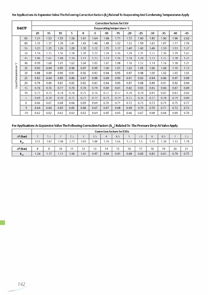
http://holodko.ru/
For Applications As Expansion Valve The Following Correction Factors (kt) Related To Evaporating And Condensing Temperatures Apply
R407FCorrection factors fo r EXV
Evaporating tem perature °C
2 0 15 1 0 5 0 -5 - 1 0 -15 - 2 0 -25 -30 -35 -40 -45
Liquid
te
mpe
ratu
re
°C
65 1.51 1.53 1.55 1.58 1.61 1.64 1 . 6 8 1.71 1.75 1.80 1.85 1.90 1.96 2 . 0 2
60 1.35 1.37 1.39 1.41 1.43 1.46 1.49 1.52 1.55 1.59 1.63 1.67 1.71 1.76
55 1.23 1.25 1.26 1.28 1.30 1.32 1.35 1.37 1.40 1.43 1.46 1.50 1.53 1.57
50 1.14 1.15 1.16 1.18 1 . 2 0 1 . 2 2 1.24 1.26 1.28 1.31 1.33 1.36 1.39 1.43
45 1.06 1.07 1.08 1 . 1 0 1 . 1 1 1.13 1.14 1.16 1.18 1 . 2 0 1.23 1.25 1.28 1.31
40 0.99 1 . 0 0 1 . 0 1 1 . 0 2 1.04 1.05 1.07 1.08 1 . 1 0 1 . 1 2 1.14 1.16 1.18 1 . 2 1
35 0.93 0.94 0.95 0.96 0.97 0.99 1 . 0 0 1 . 0 1 1.03 1.05 1.06 1.08 1 . 1 0 1.13
30 0 . 8 8 0.89 0.90 0.91 0.92 0.93 0.94 0.95 0.97 0.98 1 . 0 0 1 . 0 2 1.03 1.05
25 0.83 0.84 0.85 0 . 8 6 0.87 0 . 8 8 0.89 0.90 0.91 0.93 0.94 0.96 0.97 0.99
2 0 0.79 0.80 0.81 0.82 0.82 0.83 0.84 0.85 0.87 0 . 8 8 0.89 0.91 0.92 0.94
15 0.76 0.76 0.77 0.78 0.78 0.79 0.80 0.81 0.82 0.83 0.85 0 . 8 6 0.87 0.89
1 0 0.72 0.73 0.74 0.74 0.75 0.76 0.77 0.77 0.78 0.79 0.81 0.82 0.83 0.84
5 0.69 0.70 0.70 0.71 0.72 0.72 0.73 0.74 0.75 0.76 0.77 0.78 0.79 0.80
0 0 . 6 6 0.67 0 . 6 8 0 . 6 8 0.69 0.69 0.70 0.71 0.72 0.73 0.73 0.74 0.75 0.77
-5 0.64 0.64 0.65 0.65 0 . 6 6 0.67 0.67 0 . 6 8 0.69 0.70 0.70 0.71 0.72 0.73
- 1 0 0.62 0.62 0.62 0.63 0.63 0.64 0.65 0.65 0 . 6 6 0.67 0 . 6 8 0 . 6 8 0.69 0.70
For Applications As Expansion Valve The Following Correction Factors (kAp) Related To The Pressure Drop At Valve Apply
Correction factors for EXVs
AP (bar) 1 1.5 2 2.5 3 3.5 4 4.5 5 5.5 6 6.5 7 7.5
kAP 3.51 2.87 2.48 2 . 2 2 2.03 1 . 8 8 1.76 1 . 6 6 1.57 1.5 1.43 1.38 1.33 1.28
AP (bar) 8 9 1 0 1 1 1 2 13 14 15 16 17 18 19 2 0 2 1
kAP 1.24 1.17 1 . 1 1 1.06 1 . 0 1 0.97 0.94 0.91 0 . 8 8 0.85 0.83 0.81 0.79 0.77
142

http://holodko.ru/
Application Hot Gas Bypass - Nominal Capacities (kW)
Valve Type Kv, m3/h R 2 2 / R 40 7C R134a R 4 0 4 A / R 507
EX 4 0.21 4.9 3.4 4.6EX 5 0.68 16 11 15E X 6 1.57 37 26 35EX 7 5.58 131 92 126E X 8 16.95 399 278 382
The nominal capacity (Qn) is based on the following conditions:
Refrigerant Evaporating temperature Condensing temperature Subcooling
R407C +4°C (dew point) +38°C bubble point / +43°C dew point 1K
R22, R134a, R404A, R507 +4°C +38°C 1K
For other operating conditions use Excel based Selection Tool (download Biflow versions are not released for hot gas bypass applications. EX4 .. EX8 mustfrom www.emersonclimate.eu) or use the following quick selection tables. be installed with motor downward in hot gas line applications. This ensures
the valve life expectancy. Install a check valve on main hot gas line just after branch to Control Valve.
Condensing Temperature °C
Extended Capacity kWValve type
R 2 2 / R407C R134a R404A / R507
60 bubble point for all refrig (64 dew point for R407C)
7 4.9 5.8 EX423 16 19 EX554 38 45 EX6
191 135 161 EX7581 411 488 EX8
50 bubble point for all refrig.
(54 dew point for R407C)
6.1 4.3 5.5 EX420 14 18 EX546 32 41 EX6163 115 147 EX7495 348 447 EX8
40 bubble point for all refrig.
(45 dew point for R407C)
4.9 3.7 4.9 EX416 12 16 EX538 27 36 EX6136 95 130 EX7414 289 394 EX8
30 bubble point for all refrig.
(35 dew point for R407C)
4.3 2.8 4 EX414 9 13 EX532 22 31 EX6
112 78 111 EX7340 236 336 EX8
143

http://holodko.ru/
Application Suction Pressure Regulation (Evaporating or Crankcase Pressure) - Nominal Capacities (kW)
Valve Type Kv, m3/h R 407C R22 R134a R 4 0 4 A
E X 6 1.57 3.9 4.1 3.1 3.5EX 7 5.58 14 15 11 13E X 8 16.95 42 45 34 38
The nominal capacity (Qn) is based on the following conditions:
Refrigerant Evaporating temperature Condensing temperature Subcooling Pressure Drop
R407C +4°C (dew point) +38°C bubble point / +43°C dew point 1K 0.15 bar
R22, R134a, R404A +4°C +38°C 1K 0.15 bar
For other operating conditions use Excel based Selection Tool (download from www.emersonclimate.eu) or use the following quick selection tables.
Exam ple:EX6 provides 3.5 kW at 0 .15 bar pressure drop w ith R404A or 3 .5 *1 .41= 4 .9 kW at 0.3 bar pressure drop.
M ultip ly above nom inal capacities by fo llow ing factors to obtain capacities at different pressure drops:
For biflow versions attention should be paid to the temperature range TS -40°C bis +80°C ! EX6 .. EX8 must be installed with motor downward in suction line applications. This ensures the valve life expectancy.
Typical Order Package1) Valve EX6 , EX7 or EX 8
Plug and cable assem bly EXV-M 602) Contro ller K it EXD -U 00 Part No. 808 038
AP, bar 0.10 0.15 0.20 0.30
Correction factor 0.82 1.00 1.15 1.41
CondensingTemperature
°C
R134a Extended capacity (kW) Evaporating Temperature (°C) Valve
Type1 0 5 0 - 1 0 - 2 0
3 2 2 2 1 EX6
60 1 0 9 8 6 4 EX7
30 27 24 18 13 EX8
3 3 2 2 1 EX6
50 1 1 1 0 9 7 5 EX7
34 30 27 21 15 EX8
3 3 3 2 2 EX6
40 1 2 1 1 1 0 8 6 EX7
38 34 30 23 17 EX8
4 3 3 2 2 EX6
30 14 1 2 1 1 8 6 EX7
41 37 33 26 19 EX8
4 4 3 3 2 EX6
20 15 13 1 2 9 7 EX7
45 40 36 28 21 EX8
CondensingTemperature
°C
R22 Extended capacity (kW) Evaporating Temperature (°C) Valve
Type1 0 5 0 - 1 0 - 2 0 -30 -40
4 3 3 3 2 2 1 EX6
60 13 1 2 1 1 9 7 5 4 EX7
41 37 34 27 2 2 17 1 2 EX8
4 4 3 3 2 2 1 EX6
50 15 13 1 2 1 0 8 6 5 EX7
45 41 37 30 24 19 14 EX8
5 4 4 3 2 2 1 EX6
40 16 15 13 1 1 9 7 5 EX7
49 45 41 33 27 21 15 EX8
5 4 4 3 3 2 2 EX6
30 17 16 14 1 2 9 7 5 EX7
53 48 44 36 29 2 2 16 EX8
5 5 4 4 3 2 2 EX6
20 19 17 15 13 1 0 8 6 EX7
56 52 47 39 31 24 18 EX8
144—

http://holodko.ru/
Application Suction Pressure Regulation (Evaporating or Crankcase Pressure)
CondensingTemperature
°C
R404A/R507 Extended capacity (kW) Evaporating Temperature (°C) Valve
Type1 0 5 0 - 1 0 - 20 -30 -40
3 2 2 2 1 1 1 EX6
60 9 8 8 6 4 3 2 EX7
29 26 23 18 13 1 0 7 EX8
3 3 3 2 2 1 1 EX6
50 1 2 1 1 9 7 6 4 3 EX7
36 32 29 23 18 13 9 EX8
4 3 3 3 2 1 1 EX6
40 14 1 2 1 1 9 7 5 4 EX7
42 38 34 27 21 16 1 2 EX8
4 4 4 3 2 2 1 EX6
30 16 14 13 1 0 8 6 5 EX7
48 43 39 31 25 19 14 EX8
5 4 4 3 3 2 1 EX6
20 17 16 14 1 2 9 7 5 EX7
53 48 44 35 28 21 16 EX8
Condensing TemperatureR407C Extended capacity (kW)
Evaporating Temperature (°C) ValveTypeDew point Bubble point
°C °C 1 0 5 0 - 1 0 - 2 0
3 3 3 2 2 EX6
64 60 1 2 1 1 1 0 8 6 EX7
36 33 29 23 18 EX8
4 3 3 2 2 EX6
54 50 14 1 2 1 1 9 7 EX7
41 37 34 27 21 EX8
4 4 3 3 2 EX6
45 40 15 14 1 2 1 0 8 EX7
46 42 38 30 23 EX8
5 4 4 3 2 EX6
35 30 17 15 14 1 1 9 EX7
51 46 41 33 26 EX8
5 5 4 3 3 EX6
26 20 18 16 15 1 2 9 EX7
55 50 45 36 28 EX8
Application Condensing Pressure Regulation and Liquid Duty - Nominal Capacities (kW)
Valve Type Kv, m3/h R407C R22 R134a R404A
EX5 0. 68 18 2 0 18 13
EX6 1.57 43 46 42 30
EX7 5.58 153 162 151 106
EX8 16.95 463 491 458 323
145
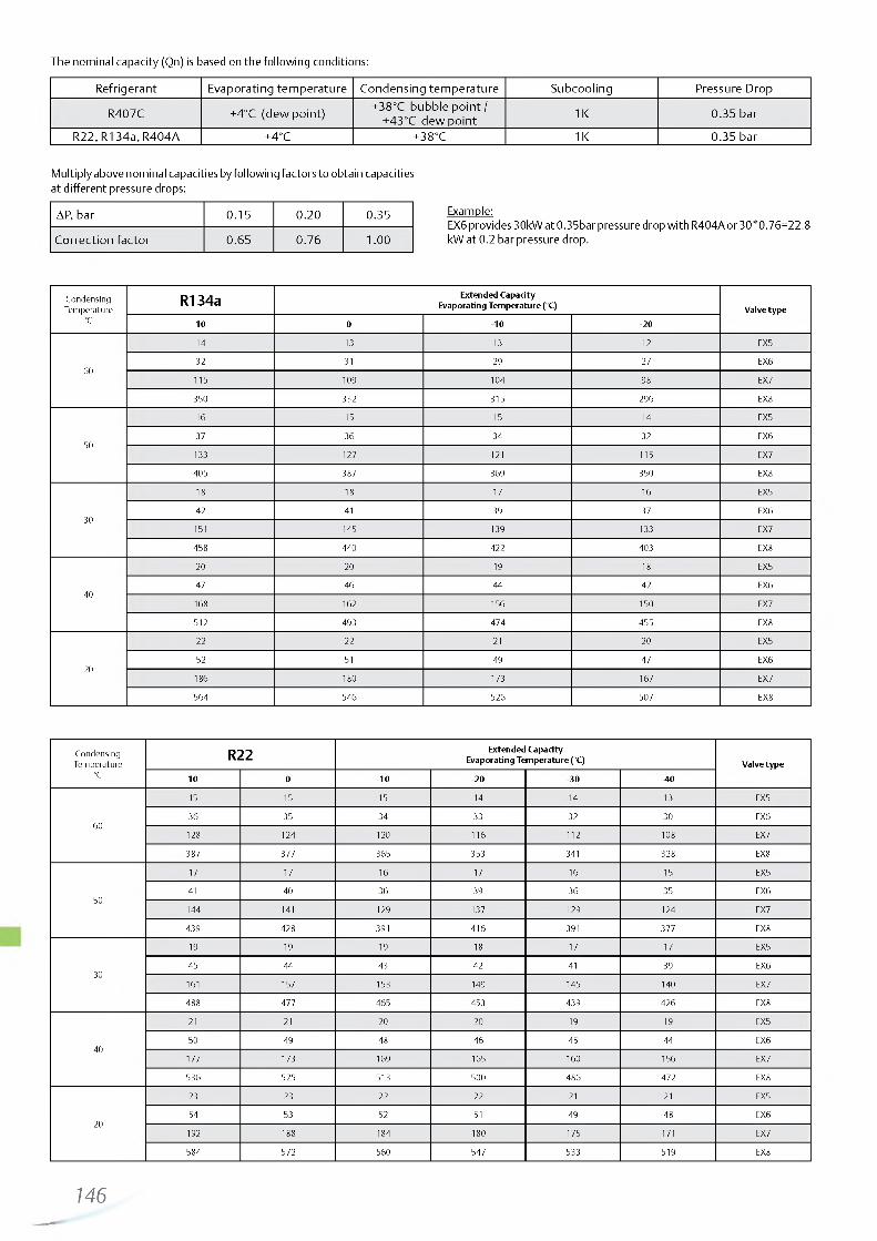
http://holodko.ru/
The nominal capacity (Qn) is based on the following conditions:
Refrigerant Evaporating temperature Condensing temperature Subcooling Pressure Drop
R407C +4°C (dew point) +38°C bubble point / +43°C dew point 1K 0.35 bar
R22, R134a, R404A +4°C +38°C 1K 0.35 bar
Example:EX6 provides 30kW at 0.35bar pressure drop with R404A or 30*0.76=22.8 kW at 0.2 bar pressure drop.
CondensingTemperature
°C
R134a Extended Cap acity Evaporating Tem perature (°C) Valve type
10 0 -10 -20
60
14 13 13 12 EX5
32 31 29 27 EX6
115 109 104 98 EX7
350 332 315 296 EX8
50
16 15 15 14 EX5
37 36 34 32 EX6
133 127 121 115 EX7
405 387 369 350 EX8
30
18 18 17 16 EX5
42 41 39 37 EX6
151 145 139 133 EX7
458 440 422 403 EX8
40
20 20 19 18 EX5
47 46 44 42 EX6
168 162 156 150 EX7
512 493 474 455 EX8
20
22 22 21 20 EX5
52 51 49 47 EX6
186 180 173 167 EX7
564 546 526 507 EX8
CondensingTemperature
°C
R22 Extended Capacity Evaporating Tem perature (°C) V alve type
10 0 -1 0 -20 -30 -40
60
15 15 15 14 14 13 EX5
36 35 34 33 32 30 EX6
128 124 120 116 112 108 EX7
387 377 365 353 341 328 EX8
50
17 17 16 17 16 15 EX5
41 40 36 39 36 35 EX6
144 141 129 137 129 124 EX7
439 428 391 416 391 377 EX8
30
19 19 19 18 17 17 EX5
45 44 43 42 41 39 EX6
161 157 153 149 145 140 EX7
488 477 465 453 439 426 EX8
40
21 21 20 20 19 19 EX5
50 49 48 46 45 44 EX6
177 173 169 165 160 156 EX7
536 525 513 500 486 472 EX8
20
23 23 22 22 21 21 EX5
54 53 52 51 49 48 EX6
192 188 184 180 175 171 EX7
584 572 560 547 533 519 EX8
146
Multiply above nominal capacities by following factors to obtain capacities at different pressure drops:
AP, bar 0.15 0.20 0.35
Correction factor 0.65 0.76 1.00
—

http://holodko.ru/
Application Condensing Pressure Regulation and Liquid DutyCondensingTemperature
°C
R404A/507 Evaporating Temperature (°C)Valve type
1 0 0 - 1 0 - 2 0 -30 -40
60
8 8 7 6 6 5 EX5
19 17 16 15 13 1 2 EX6
66 62 58 53 48 43 EX7
20 2 189 175 160 146 130 EX8
50
1 1 1 0 9 9 8 8 EX5
24 23 22 20 19 17 EX6
87 82 78 73 67 62 EX7
264 250 236 2 2 0 205 189 EX8
30
13 1 2 1 2 1 1 1 0 1 0 EX5
30 28 27 26 24 23 EX6
106 1 01 96 91 85 80 EX7
321 306 291 276 260 243 EX8
40
15 14 14 13 1 2 1 2 EX5
35 33 32 30 29 27 EX6
123 119 114 108 103 97 EX7
375 360 345 329 312 295 EX8
20
17 16 16 15 14 14 EX5
40 38 37 35 34 32 EX6
141 136 131 125 1 2 0 114 EX7
427 412 397 380 363 346 EX8
Cond<Tempe a
ss ne
g R407C Evaporating Temperature (°C)Valve type
Dew Point °C Bubble Point °C 1 0 0 - 1 0 - 2 0
64 60
14 13 1 2 1 2 EX5
32 30 29 28 EX6
1 1 2 108 103 98 EX7
340 327 313 298 EX8
54 50
16 15 15 14 EX5
37 36 35 33 EX6
132 128 123 118 EX7
402 388 373 358 EX8
45 30
18 18 17 17 EX5
43 41 40 38 EX6
152 147 142 137 EX7
460 446 431 415 EX8
35 40
21 20 19 19 EX5
48 47 45 44 EX6
170 166 160 155 EX7
517 503 487 471 EX8
26 20
23 22 22 21 EX5
53 52 50 49 EX6
189 184 179 173 EX7
573 558 543 526 EX8
147

http://holodko.ru/
Application Hot Gas Flow such as Heat Reclaim Application - Nominal Capacities (kW)
Valve Type Kv, m3/h R 2 2 / R 40 7C R134a R 4 0 4 A / R 507 R 4 1 0 A
E X 6 1.57 11 9 10 13EX 7 5.58 39 33 36 47E X 8 16.95 119 101 108 144
The nominal capacity (Qn) is based on the following conditions:
Refrigerant Evaporating temperature Condensing temperature Subcooling Pressure Drop Isentropic Efficiency
R407C +4°C (dew point) +38°C bubble point / +43°C dew point 1K 0.35 bar 80%
R22, R134a, R404A,R507 +4°C +38°C 1K 0.35 bar 80%
For other conditions see following tables. Valves must be installed with motor downward in hot gas line applications.This ensures the valve life expectancy. Bi-flow versions are not released for hot gas flow applications.
CondensingTemperature
°C
PressureDropbar
R134a Extended Capacity KW Evaporating Temperature (°C) Valve
type15 1 0 5 0 -5 - 1 0 -15 - 2 0 -25 -30 -35 -40 -45
5 5 4 4 4 4 4 4 4 3 3 3 3 EX6
0,1 16 16 16 15 15 14 14 13 13 1 2 1 2 11 1 0 EX7
50 49 47 46 44 43 41 40 38 37 35 33 32 EX8
1 0 1 0 1 0 9 9 9 8 8 8 7 7 7 6 EX6
60 0,5 36 35 34 33 32 31 30 29 28 26 25 24 23 EX7
1 1 0 107 104 1 0 1 97 94 91 87 84 80 77 74 70 EX8
14 14 13 13 1 2 1 2 1 2 1 1 1 1 1 0 1 0 9 9 EX6
1 , 0 50 49 47 46 44 43 41 40 38 37 35 34 32 EX7
152 148 144 139 135 130 126 1 2 1 116 1 1 2 107 1 0 2 97 EX8
5 4 4 4 4 4 4 4 4 3 3 3 3 EX6
0,1 16 16 15 15 14 14 14 13 13 1 2 1 2 11 1 1 EX7
49 48 47 45 44 43 41 40 39 37 36 35 33 EX8
1 0 1 0 9 9 9 9 8 8 8 8 7 7 7 EX6
50 0,5 35 35 34 33 32 31 30 29 28 27 26 25 24 EX7
108 105 1 0 2 99 97 94 91 88 85 82 79 76 73 EX8
14 13 13 13 1 2 1 2 1 2 1 1 1 1 1 0 1 0 1 0 9 EX6
1 , 0 49 48 46 45 44 43 41 40 39 37 36 34 33 EX7
148 145 141 137 133 129 125 1 2 1 117 113 109 105 1 0 0 EX8
4 4 4 4 4 4 4 4 4 3 3 3 3 EX6
0,1 16 15 15 14 14 14 13 13 13 1 2 1 2 1 1 1 1 EX7
47 46 45 44 43 42 40 39 38 37 36 34 33 EX8
1 0 9 9 9 9 8 8 8 8 7 7 7 7 EX6
40 0,5 34 33 32 32 31 30 29 28 27 26 26 25 24 EX7
103 1 00 98 96 93 91 88 86 83 80 78 75 73 EX8
13 13 1 2 1 2 1 2 1 2 11 1 1 1 1 1 0 1 0 1 0 9 EX6
1 , 0 46 45 44 43 42 41 40 39 38 36 35 34 33 EX7
141 138 134 131 128 124 1 2 1 117 114 1 1 0 107 103 1 00 EX8
4 4 4 4 4 4 4 3 3 3 3 3 3 EX6
0,1 15 14 14 14 13 13 13 1 2 1 2 1 2 1 1 1 1 1 1 EX7
44 43 42 42 41 40 39 38 37 35 34 33 32 EX8
9 9 9 8 8 8 8 8 7 7 7 7 6 EX6
30 0,5 32 31 30 30 29 28 28 27 26 25 25 24 23 EX7
96 94 92 90 88 86 84 81 79 77 75 72 70 EX8
1 2 1 2 1 2 1 1 1 1 1 1 1 1 1 0 1 0 1 0 9 9 9 EX6
1 , 0 43 42 41 40 39 38 37 36 35 34 33 32 31 EX7
130 128 125 1 2 2 119 117 114 1 1 1 108 105 1 0 2 98 95 EX8
148—

http://holodko.ru/
Application Hot Gas Flow such as Heat Reclaim Application
CondensingTemperature
°C
PressureDropbar
R22/R407C Extended Capacity KW Evaporating Temperature (°C) Valve
type15 1 0 5 0 -5 - 1 0 -15 - 2 0 -25 -30 -35 -40 -45
6 5 5 5 5 5 5 5 4 4 4 4 4 EX6
0,1 20 19 19 18 18 17 17 16 16 15 15 14 14 EX7
59 58 57 55 54 53 51 50 48 47 45 44 42 EX8
1 2 1 2 1 2 1 1 1 1 1 1 1 0 1 0 1 0 1 0 9 9 9 EX6
60 0,5 43 42 41 40 39 38 37 36 35 34 33 32 31 EX7
131 129 126 123 119 116 113 1 1 0 107 103 1 00 97 94 EX8
17 17 16 16 15 15 15 14 14 13 13 13 1 2 EX6
1 , 0 60 59 58 56 55 53 52 51 49 48 46 45 43 EX7
183 179 175 171 167 162 158 154 149 145 140 135 131 EX8
5 5 5 5 5 5 5 5 4 4 4 4 4 EX6
0,1 19 19 18 18 17 17 17 16 16 15 15 14 14 EX7
58 57 56 54 53 52 51 49 48 47 45 44 42 EX8
1 2 1 2 1 1 1 1 1 1 1 1 1 0 1 0 1 0 1 0 9 9 9 EX6
50 0,5 42 41 40 40 39 38 37 36 35 34 33 32 31 EX7
128 126 123 1 2 0 117 115 1 1 2 109 106 103 1 0 0 97 94 EX8
17 16 16 15 15 15 14 14 14 13 13 13 1 2 EX6
1 , 0 59 57 56 55 54 52 51 50 49 47 46 44 43 EX7
178 175 171 167 163 159 155 151 147 143 139 135 131 EX8
5 5 5 5 5 5 5 4 4 4 4 4 4 EX6
0,1 18 18 18 17 17 16 16 16 15 15 15 14 14 EX7
56 55 54 52 51 50 49 48 47 45 44 43 42 EX8
1 1 1 1 1 1 1 1 1 0 1 0 1 0 1 0 9 9 9 9 8 EX6
40 0,5 40 40 39 38 37 36 35 35 34 33 32 31 30 EX7
123 1 2 0 118 115 113 1 1 0 108 105 103 1 0 0 97 94 92 EX8
16 15 15 15 14 14 14 14 13 13 1 2 1 2 1 2 EX6
1, 0 56 55 54 53 52 50 49 48 47 46 44 43 42 EX7
170 167 163 160 157 153 149 146 142 139 135 131 127 EX8
5 5 5 5 4 4 4 4 4 4 4 4 4 EX6
0,1 17 17 17 16 16 16 15 15 15 14 14 14 13 EX7
53 52 51 50 49 48 46 45 44 43 42 41 40 EX8
1 1 1 0 1 0 1 0 1 0 1 0 9 9 9 9 9 8 8 EX6
30 0,5 38 37 37 36 35 34 34 33 32 31 30 30 29 EX7
115 113 1 1 1 109 107 104 1 0 2 1 0 0 97 95 93 90 88 EX8
15 14 14 14 14 13 13 13 1 2 1 2 1 2 1 2 1 1 EX6
1 , 0 52 51 50 49 48 47 46 45 44 43 42 41 40 EX7
159 156 153 150 147 144 141 138 134 131 128 124 1 2 1 EX8
* Condensing tem peratures R 407C :The relation betw een bubble points and dew points is as fo llow s:
Bubble point °C Dew point °C
60 6450 5440 4 530 35
149

http://holodko.ru/
Application Hot Gas Flow such as Heat Reclaim Application
CondensingTemperature
°C
PressureDropbar
R404A Extended Capacity KW Evaporating Temperature (°C) Valve
type15 1 0 5 0 -5 - 1 0 -15 - 2 0 -25 -30 -35 -40 -45
4 4 4 4 4 3 3 3 3 3 3 2 2 EX6
0,1 15 14 14 13 13 1 2 1 1 1 1 1 0 1 0 9 8 8 EX7
45 43 42 40 38 36 35 33 31 29 27 25 23 EX8
9 9 8 8 8 7 7 7 6 6 6 5 5 EX6
60 0,5 32 31 30 29 28 26 25 24 22 21 20 18 17 EX7
99 95 92 88 84 80 76 72 68 64 60 56 52 EX8
13 1 2 1 2 11 1 1 1 0 1 0 9 9 8 8 7 7 EX6
1, 0 45 44 42 40 39 37 35 33 31 29 27 26 24 EX7
137 132 127 1 2 2 117 1 1 2 106 1 0 1 95 89 84 78 72 EX8
5 4 4 4 4 4 4 4 3 3 3 3 3 EX6
0,1 16 16 15 15 14 14 13 13 1 2 1 1 1 1 1 0 1 0 EX7
49 47 46 44 43 41 40 38 36 35 33 31 30 EX8
1 0 1 0 9 9 9 8 8 8 7 7 7 6 6 EX6
50 0,5 35 34 33 32 31 30 29 28 26 25 24 23 22 EX7
107 104 1 01 98 95 91 88 84 80 77 73 69 65 EX8
14 13 13 13 1 2 1 2 1 1 1 1 1 0 1 0 9 9 8 EX6
1, 0 49 48 46 45 43 42 40 38 37 35 33 32 30 EX7
149 145 141 136 131 127 1 2 2 117 1 1 2 107 1 0 2 96 91 EX8
5 4 4 4 4 4 4 4 4 3 3 3 3 EX6
0,1 16 16 16 15 15 14 14 13 13 1 2 1 2 1 1 1 1 EX7
50 49 47 46 45 43 42 40 39 37 36 34 33 EX8
1 0 1 0 1 0 9 9 9 9 8 8 8 7 7 7 EX6
40 0,5 36 35 34 33 32 31 30 29 28 27 26 25 24 EX7
109 107 104 1 0 1 98 95 92 89 86 83 79 76 73 EX8
14 14 13 13 13 1 2 1 2 1 1 1 1 1 1 1 0 1 0 9 EX6
1,0 50 49 48 46 45 44 42 41 39 38 36 35 33 EX7
152 148 144 140 136 132 128 124 119 115 1 1 0 105 1 0 1 EX8
5 4 4 4 4 4 4 4 4 4 3 3 3 EX6
0,1 16 16 15 15 15 14 14 13 13 13 1 2 1 2 11 EX7
49 48 47 46 45 43 42 41 40 38 37 36 34 EX8
1 0 1 0 1 0 9 9 9 9 8 8 8 8 7 7 EX6
30 0,5 35 35 34 33 32 31 31 30 29 28 27 26 25 EX7
108 105 103 1 01 98 95 93 90 87 84 81 78 76 EX8
14 13 13 13 13 1 2 1 2 1 2 1 1 1 1 1 0 1 0 1 0 EX6
1 , 0 49 48 47 46 45 43 42 41 40 38 37 36 34 EX7
149 146 142 139 135 132 128 124 1 2 0 117 113 109 104 EX8
150

http://holodko.ru/
Application Hot Gas Flow such as Heat Reclaim Application
CondensingTemperature
°C
Pressure Drop bar
R410A Extended Capacity KW Evaporating Temperature (°C) Valve
type15 1 0 5 0 -5 - 1 0 -15 - 2 0 -25 -30 -35 -40 -45
6 6 6 6 5 5 5 5 5 5 4 4 4 EX6
0,1 21 21 20 20 19 19 18 18 17 16 16 15 15 EX7
64 63 62 60 58 57 55 53 52 50 48 46 44 EX8
13 13 13 1 2 1 2 1 2 11 1 1 1 1 1 0 1 0 1 0 9 EX6
60 0,5 47 46 45 44 43 41 40 39 38 36 35 34 32 EX7
143 140 137 133 130 126 1 2 2 118 115 1 1 1 107 103 99 EX8
19 18 18 17 17 16 16 15 15 14 14 13 13 EX6
1, 0 66 64 63 61 60 58 56 55 53 51 49 47 46 EX7
200 196 191 186 182 177 171 166 161 155 150 144 138 EX8
6 6 6 6 6 6 5 5 5 5 5 5 4 EX6
0,1 22 22 21 21 20 20 19 19 18 18 17 17 16 EX7
67 66 65 63 62 60 59 57 55 54 52 50 48 EX8
14 14 13 13 13 1 2 1 2 1 2 1 1 1 1 1 1 1 0 1 0 EX6
50 0,5 49 48 47 46 45 44 43 42 40 39 38 37 35 EX7
149 146 143 140 137 133 130 126 123 119 115 1 1 1 108 EX8
19 19 19 18 18 17 17 16 16 15 15 14 14 EX6
1 , 0 69 67 66 64 63 61 60 58 57 55 53 51 50 EX7
209 204 200 196 191 186 182 177 172 167 161 156 151 EX8
6 6 6 6 6 6 5 5 5 5 5 5 5 EX6
0,1 2 2 22 21 21 20 20 19 19 18 18 17 17 16 EX7
67 66 65 63 62 60 59 58 56 54 53 51 50 EX8
14 13 13 13 13 1 2 1 2 1 2 1 1 1 1 1 1 1 1 1 0 EX6
40 0,5 49 48 47 46 45 44 43 42 41 40 39 37 36 EX7
148 146 143 140 137 134 131 127 124 1 2 1 117 114 1 1 0 EX8
19 19 18 18 18 17 17 16 16 16 15 15 14 EX6
1 , 0 68 67 66 64 63 61 60 59 57 55 54 52 51 EX7
207 203 199 195 191 187 182 178 173 168 164 159 154 EX8
6 6 6 6 6 5 5 5 5 5 5 5 5 EX6
0,1 21 21 21 20 20 19 19 19 18 18 17 17 16 EX7
65 64 63 61 60 59 58 56 55 53 52 51 49 EX8
13 13 13 13 1 2 1 2 1 2 1 2 1 1 1 1 1 1 1 0 1 0 EX6
30 0,5 47 46 45 45 44 43 42 41 40 39 38 37 36 EX7
143 141 138 135 133 130 127 124 1 2 1 118 115 1 1 2 109 EX8
18 18 18 17 17 17 16 16 16 15 15 14 14 EX6
1 , 0 65 64 63 62 61 60 58 57 56 54 53 51 50 EX7
199 195 192 188 185 181 177 173 169 165 160 156 152 EX8
151

http://holodko.ru/
Electrical Control Valves Series EX4, EX5, EX6, EX7, EX8
Technical Data
Compatibility * HCFCs, HFCs, CO2 Mineral and POE lubricants
MOPD (maximum operating pressure differential)
EX4/EX5/EX6/EX7: 35 bar EX8: 30 bar
Max. allowable pressure, PS EX4/EX5/EX6/EX7: 60 bar EX8: 45 bar
Medium temperature range: Uniflow version Biflow version
Liquid inlet temperature TS: -50 ... +100°C TS: -40 ... +80°C
Ambient temperature Storage temperature
-40 ... +55°C -40 ... +70°C
CE markingEX4/EX5EX6/EX7/EX8
not requiredrequired, Cat I, Module A
Salt spray test non-corrosion stainless steel body
Humidity 5 ... 95% R.H.
* Valves are not released for use with inflammable refrigerants.
Block Diagrams
Superheat Control w ith EC3-X33 (see page 160) optional d isplay un it ECD-002
I ECN-N60 sensor4 PT5 pressure transm itter6 Supply / D igital Input9 A larm outI I EX4 ... EX8 valve12 Suction pressure 4 ..2 0 m A out13 ECD-002 D isp lay unit
Connections ODF stainless steel fittings
Protection accordance to IEC 529, DIN 40050
IP 67 with Alco supplied cable connector assembly
Vibration for non-connected and fastened valve
4 g(0 .. 1000 Hz, 1 Oktave /min.)
Shock 20g at 11 ms, 80g at 1 msNet weight 0.5 kg (EX4), 0.52 kg (EX5),
0.6 kg (EX6), 1.1 kg (EX7), 1.5 kg (EX8)
Full travel time EX4/EX5/EX6: 1.5 sec EX7: 3.2 sec., EX8 : 5.2 sec
Seat leakage Positive shut-off better than solenoid valve
External leakage < 3 g / Year
Package and delivery Single pack, without electrical connector
Refrigerant Mass Flow Control w ith EXD-U(see page 164)
152

http://holodko.ru/
High Pressure Expansion Valves Series CX4, CX5, CX6, CX7
Em erson C lim ate Technologies C X series are stepper m otor driven valves for precise control of R744 (CO 2) refrigerant mass flow in air conditioning, refrigeration , heat pum p applications. The Control Valves can be used as high pressure expansion valve , liquid in jection duty, hot gas bypass.
Features and BenefitsM axim um allowable pressure, PS: 120 bar Test pressure, PT: 172 bar Burst pressure: >360 barFully herm etic design (no thread jo in ts betw een valve body and m otor com p artm ent)Applicab le to transcritica l CO2 applications V ery sho rt full stroke tim e High resolution and excellent repeatab ility Positive shut-off of valve to e lim inate the use o f an additional solenoid valve Linear flow capacityExtrem ely w ide capacity range (10 ... 100%)Continuous m odulation of m ass flow , no stress (liquid ham m ering) in the refrigeration c ircu it D irect coupling of m otor and valve for high reliab ility (no gear m echan ism )Ceram ic slide and port for accurate flow and m inim al w ear Balanced force designCorrosion resistan t sta in less steel body and connections 40 m icron internal strainer
f l
'■ X
VSelection Chart
Type Part No. Kv, m3/h Capacity Range Inlet Connection ODF
Outlet Connection ODF
ElectricalConnection
CX4-CO2 801 990 0.21
10 ... 100%
3/8” 5/8”
M12 plugCX5-CO2 801 991 0.68 5/8” (16 mm) 7/8” (22 mm)CX6-CO2 801 992 1.57 7/8” 1-1/8”CX7-CO2 801 996 5.58 1-1/8” 1-1/8”
Cable and Connector Assemblies
Type Part No. Temperature Range Length Connector type to valve Connector type to driver or controller Illustration
EXV-M15 804 663-50 ... +80°C
1.5 mM12, 4 pins Loose wires
■ oEXV-M30 804 664 3.0 mEXV-M60 804 665 6.0 m
Controllers:EXD -U 00 Universal D river M odule page 161EC3-X32 Superheat Contro ller page 164EC3-X33 Superheat Contro ller page 160EC3-D72 Digital Superheat Contro ller page 160EC3-D73 Digital Superheat Contro ller page 160
153

http://holodko.ru/
154__—

http://holodko.ru/
Electronic Controllers and Sensors

http://holodko.ru/
Electronic Controllers and Sensors
Selection Table Electronic Controllers
N etw ork Com m unicationDescription Page
W ith o u t TCP/IP LON
Superheat Contro llers And Stepper M otor D rivers
Superheat controller for electrical control valves EX4 ... EX8 EC3-X33 EC3-X32 160
Digital superheat controller for electrical control valves EX4 ... EX6 EC3-D73 EC3-D72 160
Universal stepper driver module for electrical control valves EX4 ... EX8 EXD-U00 164
Display Case And Cold Room Contro llers For Therm o™ Expansion Valve ApplicationsThermostat control EC2-212 EC2-221 165
version for use with a compressor pack system EC2-292 EC2-291 165
Display Case And Cold Room Contro llers For Electrica l Control ValveTemperature + superheat control of EX2 (pressure/temperature input) EC2-352 EC2-351 165
version for use with a compressor pack system EC2-272 EC2-271 165
Temperature + superheat control of EX2 (temperature/temperature input) EC2-312 EC2-311 165
version for use with a compressor pack system EC2-392 EC2-391 165
Temperature + superheat control of EX4 ... EX8 (stepper motor) EC3-332 EC3-331 168
Condensing Unit Contro llers
For 2 single stage compressors and 2 fans, on/off control EC2-512 165
For 1 Digital ScrollTM and 1 single stage or 2 single stage compressors,fans speed control with FSP EC2-552 165
Rack Contro llers And Dual C ircu it Controllers
For 8 single stage compressors or 7 compressors and 1 Digital Scroll™ EC3-652 168
For multistage compressors EC3-672 168
Dual circuits with 4 + 3 single stage compressors EC3-812 168
Dual circuits, 4 compressors one of which a Digital Scroll™, 3 condenser fans + speed control EC3-932 168
Condenser Contro llers
For up to 4 fans EC2-712 EC2-711 165
With fan speed control, 2 digital outputs EC2-742 EC2-741 165
For up to 6 stages, one with continuous control output 0 ... 10V, heat recovery control EC3-752 165
Electronic Fan Speed Contro llers
Pressure actuated, current range 0.1 ... 4A FSY 184
Current range 0.3 ... 8A, 1- or 3-phase versions FSP-FSE 186
Com pressor So ft Starter
For single phase compressor motors with up to 32A CSS 181
Pressure Transm itter
Output signal 4 ... 20mA PT5 182
Universal Contro llers
W ith 2 digital inputs, 3 temperature inputs, 4 relay outputs EC2-112 EC2-111 165
156—
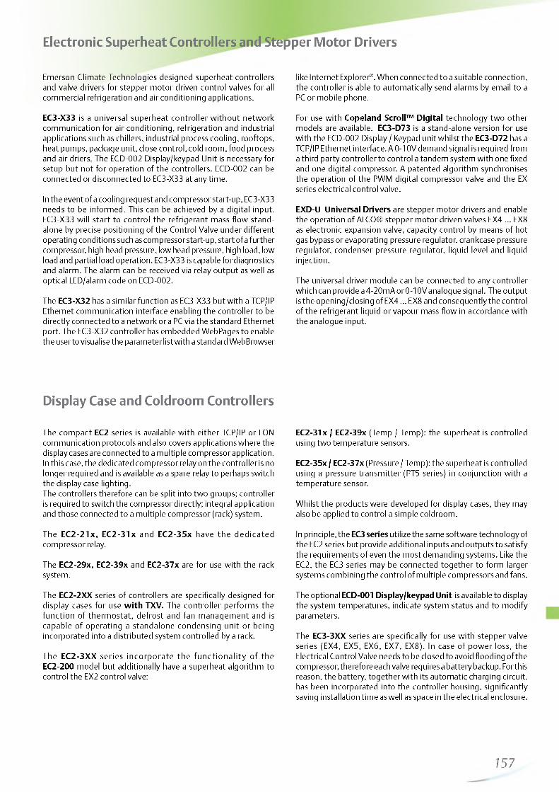
http://holodko.ru/
Electronic Superheat Controllers and Stepper Motor Drivers
Emerson Climate Technologies designed superheat controllers and valve drivers for stepper motor driven control valves for all commercial refrigeration and air conditioning applications.
EC3-X33 is a universal superheat controller w ithout network communication for air conditioning, refrigeration and industrial applications such as chillers, industrial process cooling, rooftops, heat pumps, package unit, close control, cold room, food process and air driers. The ECD-002 Display/keypad Unit is necessary for setup but not for operation of the controllers. ECD-002 can be connected or disconnected to EC3-X33 at any time.
In the event of a cooling request and compressor start-up, EC3-X33 needs to be informed. This can be achieved by a digital input. EC3-X33 will start to control the refrigerant mass flow standalone by precise positioning of the Control Valve under different operating conditions such as compressor start-up, start of a further compressor, high head pressure, low head pressure, high load, low load and partial load operation. EC3-X33 is capable for diagnostics and alarm. The alarm can be received via relay output as well as optical LED/alarm code on ECD-002.
The EC3-X32 has a similar function as EC3-X33 but with a TCP/IP Ethernet communication interface enabling the controller to be directly connected to a network or a PC via the standard Ethernet port. The EC3-X32 controller has embedded WebPages to enable the user to visualise the parameter list with a standard WebBrowser
like Internet Explorer®. When connected to a suitable connection, the controller is able to automatically send alarms by email to a PC or mobile phone.
For use with Copeland Scroll™ Digital technology two other models are available. EC3-D73 is a stand-alone version for use with the ECD-002 Display / Keypad unit whilst the EC3-D72 has a TCP/IP Ethernet interface. A 0-10V demand signal is required from a third party controller to control a tandem system with one fixed and one digital compressor. A patented algorithm synchronises the operation of the PWM digital compressor valve and the EX series electrical control valve.
EXD-U Universal Drivers are stepper motor drivers and enable the operation of ALCO® stepper motor driven valves EX4 ... EX8 as electronic expansion valve, capacity control by means of hot gas bypass or evaporating pressure regulator, crankcase pressure regulator, condenser pressure regulator, liquid level and liquid injection.
The universal driver module can be connected to any controller which can provide a 4-20mA or 0-10V analogue signal. The output is the opening/closing of EX4 ... EX8 and consequently the control of the refrigerant liquid or vapour mass flow in accordance with the analogue input.
Display Case and Coldroom Controllers
The compact EC2 series is available with either TCP/IP or LON communication protocols and also covers applications where the display cases are connected to a multiple compressor application. In this case, the dedicated compressor relay on the controller is no longer required and is available as a spare relay to perhaps switch the display case lighting.The controllers therefore can be split into two groups; controller is required to switch the compressor directly; integral application and those connected to a multiple compressor (rack) system.
The EC2-21x, EC2-31x and EC2-35x have the dedicated compressor relay.
The EC2-29x, EC2-39x and EC2-37x are for use with the rack system.
The EC2-2XX series of controllers are specifically designed for display cases for use w ith TXV. The controller performs the function of therm ostat, defrost and fan management and is capable of operating a standalone condensing unit or being incorporated into a distributed system controlled by a rack.
The EC2-3XX series incorporate the fu n c tio n a lity of the EC2-200 model but additionally have a superheat algorithm to control the EX2 control valve:
EC2-31x / EC2-39x (Temp / Temp): the superheat is controlled using two temperature sensors.
EC2-35x / EC2-37x (Pressure / Temp): the superheat is controlled using a pressure transmitter (PT5 series) in conjunction with a temperature sensor.
Whilst the products were developed for display cases, they may also be applied to control a simple coldroom.
In principle, the EC3 series utilize the same software technology of the EC2 series but provide additional inputs and outputs to satisfy the requirements of even the most demanding systems. Like the EC2, the EC3 series may be connected together to form larger systems combining the control of multiple compressors and fans.
The optional ECD-001 Display/keypad Unit is available to display the system temperatures, indicate system status and to modify parameters.
The EC3-3XX series are specifically for use with stepper valve series (EX4 , EX5, EX6 , EX7, EX8). In case of power loss, the Electrical Control Valve needs to be closed to avoid flooding of the compressor, therefore each valve requires a battery backup. For this reason, the battery, together with its automatic charging circuit, has been incorporated into the controller housing, significantly saving installation time as well as space in the electrical enclosure.
157

http://holodko.ru/
Condensing Units, Rack and Condenser Controllers
Condensing Unit Controllers
The EC2-500 series of controllers are suitable for controlling the compressors and fans of a condensing unit. Digital inputs are available for individual compressor feedback loops from the safety chain, which typically consists of low and high pressure switches together with motor protection and oil management controls. A common feedback is also available for the fans.
Following models are available:
EC2-512: to control up to 2 compressors (on/off control) and 2 fans (on/off control).
EC2-552: to control up to 2 single stage compressors or tandem compressor condensing units with a Copeland Scroll™ Digital compressor. It features a 0 ...10V output to connect to an Alco Controls FSP fan speed power module for variable fan speed control. Alternatively this output may be used to control fan motor speed with an inverter or to connect to ECM type fan motors directly.
Condenser Controllers
The EC2-7xx series provide an economical solution for condenser control.
Two models are available:
EC2-71x: to control up to 4 fans, on/off. A feedback loop is available for each fan.
EC2-74x: provides a 0 ...10V output to feed FSP series fan speed power modules. Several FSP modules may be connected in parallel to speed control all fans simultaneously.
The EC3 series provides additional inputs and outputs to satisfy the requirements of even the most demanding systems:
EC3-752: for condensers with up to 6 stages, one with continous control output 0 ... 10V, heat recovery control.
The optional ECD-000 Display/keypad Unit is available to display the system temperatures, indicate system status and to modify parameters.
Rack and Condenser Controllers
The EC3 series utilize in principle the same software technology of the EC2 series but provide additional inputs and outputs to satisfy the requirements of even the most demanding systems. Like the EC2, the EC3 series may be connected together to form larger systems combining the control of multiple compressors and fans. Many controllers include 0...10V outputs that may be used in conjunction with frequency inverters and/or the FSP series of fan speed power modules.
Com monly referred to as “ hot application contro llers” , the EC3-652, EC3-672, EC3-752, EC3-812, EC3-932 series contro lle rs are designed for the contro l of com pressors and condensers. Racks with one or two suction groups and up to 8 single stage com pressors including a Copeland Scroll™ Digital or 6 multistage compressors can be managed. EC3-652 and EC3-932 series have been designed to control a Copeland Scroll™ Digital and incorporate a triac to switch the PWM solenoid.
The control of condenser arrays with up to 6 fan stages as well as a combined control of Rack and Condenser is also possible. Refer to the table on page 156 for a complete product listing.
The optional ECD-000 Display/keypad Unit is available to display the system temperatures, indicate system status and to modify parameters.
The Universal Series of Controllers are useful additions to the series. They are typ ically used to enable the monitoring of temperatures from integral display cases that do not have communication facilities as well as potentially providing additional input and output functionality to control systems. Examples of such applications could be for switching display case lighting or for the monitoring of individual pressure switches on multiple compressor Racks.
PT5 series pressure transmitters are used to measure the suction and discharge pressures to modulate the compressor and fan capacities.
158

http://holodko.ru/
Network Communication and System Management
The Alco EC Series of drivers and controllers utilise the very latest in communication technology which is setting new standards in the refrigeration industry. Energy saving algorithms are incorporated into many of the controllers including: adaptive superheat and therm ostat m odulation, defrost on demand & suction and discharge setpoint shift.All EC2 or EC3 controllers are available in two communication protocols TCP/IP Ethernet and LON.
TCP/IP Ethernet:The controllers are Ethernet based enabling them to be connected directly to any computer via the Ethernet port (RJ45 connector). The controllers act as web server enabling the engineer to pick-up standard configuration pages directly from the controllers without the need of any additional hardware or software. Each controller can be connected to the PC using a crossover cable however, the most convenient way to connect a controller to the PC is to use a router that will automatically assign a TCP/IP address. Either way, the engineer can access the monitoring and parameter configuration pages by entering the TCP/IP number into the address line of an Internet browser such as Mozilla or Microsoft Internet Explorer. User name and password protection is provided to protect the controller from unauthorized access.
The TCP/IP based Controllers offer a practical solution, particularly for smaller installations that require communication for monitoring purposes without the need for customized visualization. For many installations, an additional monitoring server is not required.
LON Protocol:A range of free-topology LON FTT10-based controllers is available and complements the TCP/IP controller series. LON is an open system protocol created by Echelon and therefore benefits from not being tied to a restrictive third party protocol.
LON-based controllers can be connected to each other to form simple networks for applications requiring master / slave or synchronized defrosting. However, they can also be connected to a Monitoring Server to fulfill the most sophisticated system requirements.
The Monitoring Server acts as an interface from the LON network containing EC2 and EC3 to the outside world. Remote access can be made using standard telephone line; analog or digital ISDN. Alternatively, data can be transmitted via the Internet or a dedicated company Intranet using TCP/IP. Either way, visualization may be made using an industry standard Internet web browser.
By transmitting the system status information as temperatures or pressures used to control the refrigeration circuit in each subsystem, together with other vital system data, the system administrator can potentially identify system failures before they become an expensive stock loss situation. Should a system failure occur, the controllers automatically transfer to an emergency- operating mode whilst sending a system error message to the monitoring server.
The benefit of a centralized data acquisition system is that it can dramatically reduce the costs associated with food, which cannot be sold as a result of failing to meet the criteria set by the food hygiene regulations.
The monitoring server is typically connected to an analog or digital phone line and can communicate a system alarm to a remote location via fax, email or SMS. In a similar way to the TCP/ IP controllers, the engineer can visualize the system without the need of any additional hardware or software. The system can be visualized by entering the TCP/IP address of the monitoring server into the address line of the Internet web browser. In fact, the advancement of telecommunication systems are such that a maintenance engineer equipped with a laptop computer and mobile telephone can interact with the system from any location.
Other Functions:- Monitoring of system temperatures and pressures as well as relay status information- Read/write of EC2 & EC3 control parameters- Real time graphical visualization- Log function of up to one months data directly
on the controller- Log function of data to a PC *- Storage and retrieval of system parameter- Local alarms via email *- Remote alarms via email **
* Controller must be connected to the PC** Router must be connected to an external
telephone line and / or the Internet via an Internet Service Provider (ISP)
159
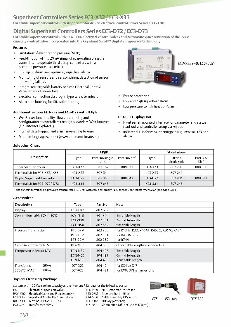
http://holodko.ru/
Superheat Controllers Series EC3-X32 / EC3-X33For stable superheat control with stepper motor driven electrical control valves Series EX4 - EX8
Digital Superheat Controllers Series EC3-D72 / EC3-D73For stable superheat control with EX4...EX6 electrical control valves and automatic synchronisation of the PWMcapacity control valve incorporated into the Copeland Scroll™ Digital compressor technology
Features• Limitation of evaporating pressure (MOP)• Feed-through of 4 ... 20mA signal of evaporating pressure
transmitter to operate third party controllers with a common pressure transmitter
• Intelligent alarm management, superheat alarm• Monitoring of sensors and sensor wiring, detection of sensor
and wiring failures• Integral rechargeable battery to close Electrical Control
Valve in case of power loss• Electrical connection via plug-in type screw terminals• Aluminum housing for DIN rail mounting
Additional features EC3-X32 and EC3-D72 with TCP/IP• Webserver functionality allows monitoring and
configuration of controllers through a standard Web browser (e.g. Internet Explorer®)
• Internal data logging and alarm messaging by email• Multiple language support (www.emersonclimate.eu)
Selection Chart
DescriptionTC P/IP S tan d a lo n e
Type Part No. single unit
Part No. Kit* Type Part No. single unit
Part No. Kit*
Superheat Controller EC3-X32 807782 808037 EC3-X33 807 783 808036
Terminal Kit for EC3-X32/-X33 K03-X32 807 644 K03-X33 807 645Digital Superheat Controller EC3-D72 807805 808 042 EC3-D73 807 804 808 041Terminal Kit for EC3-D72/-D73 K03-331 807 648 K03-331 807 648
* Kits contain terminal kit, pressure transmitter PT5-07M with cable assembly, NTC sensor 6 m, transformer 60VA (see page 286)
Accessoires
Description Type Part No. NoteDisplay ECD-002 807 657Connection cable EC3 to ECD ECC-N10 807 860 1m cable length
ECC-N30 807 861 3m cable lengthECC-N50 807 862 5m cable length
Pressure Transmitter PT5-07M 802 350 for R134a, R22, R404A, R407C, R507C, R124PT5-18M 802 351 for R410A onlyPT5-30M 802 352 for R744
Cable Assembly for PT5 PT4-M60 804805 other cable lengths see page 182Temperature Sensor NTC ECN-N30 804 496 3m cable length
ECN-N60 804 497 6m cable lengthECN-N99 804 499 12m cable length
Transformer 25VA ECT-323 804 424 for EX4 to EX7230V/24V AC 60VA ECT-623 804 421 for EX8, DIN rail mounting
Typical Ordering Package
System with 100 kW cooling capacity and refrigerant EX6 Electronic Expansion ValveEXV-M60 Electrical Cable and Plug assembly EC3-X33 Superheat Controller Stand-alone K03-X33 Terminal Kit for EC3-X33 ECT-323 Transformer 25VA
160
R22 requires the following parts:ECN-N60 NTC Temperature Sensor PT5-07M Pressure Transmitter PT4-M60 Cable assembly PT5 6.0m ECD-002 Display (optional)ECC-N30 Connection cable EC3 to ECD (opt.)
PT5 PT4-Mxx ECT-323
with ECD-002
• Freeze protection• Low and high superheat alarm• Low pressure switch function/alarm
ECD-002 Display Unit• Front panel mounted interface for parameter and status
read-out and controller setup via keypad• Indicator LEDs for valve opening/closing, external ON and
alarm

http://holodko.ru/
EXD-HP1/2 are stand-alone universal superheat and or economizer controllers for heat pumps, heating units, air conditioning and precision cooling such as telecom and shelter applications.
Features EXD-HP1/2
Self adapting superheat/economizer control in conjunction with EMERSON stepper motor driven electronic expansion Valves EXM/EXLDischarge hot gas temperature control by liquid/vapor injection to compressor EXD-HP1: Controller with one EXV output EXD-HP2: Controller with two independent EXV outputs Controllers as slave with Modbus (RTU) communication capability. All data (read/write) accessible by any third party controller having modbus communication (RTU) Upload/download Key (accessory) for transmission of parameter settings among controllers with the same setting Low pressure switch and freeze protection function Manual positioning of valve(s)Limitation of evaporating pressure (MOP)Low/high superheat alarmMonitoring of sensors and sensor wiring / detection of sensor and wiring failures
*1 V VDE approval (pending)Integrated display (3-digits LEDs) and keyboard Electrical connection via plug-in type screw terminals (included with controller)DIN rail mounting housingOEM product: Box/order quantities: 20 pieces (Multipack)
fSi S 5 0 1*3 a 0i a t m m. o* w<-----*v<----- »
H P ?
EXD-HP2
Selection Chart
Description TypePCN
M = M ultipack (20 pieces) Singlepack
Controller with one EXV output EXD-HP1 807 836M -
Controller with two EXV outputs EXD-HP2 807 837M -
Temperature sensor with 3 meter cable ECP-P30 - 804 495
Valve: EXM-B0B 800 400M -Valve: EXM-B0D 800 401M -Valve: EXM-B0E 800 402M -
Electronic expansion valves Coil: EXM-125 800 403M -see page 129 Valve: EXL-B1F 800 405M -
Valve: EXL-B1G 800 406M -Coil: EXL-125 800 407M -
Pressure sensors (Suction pressure)- 0 .8 .7 bar (R22, R134a, R407C) PT5-07M / PT5-07T 802 350M / 802 370M 802 350 / 802 3700 ......18 bar (R410A, R32) PT5-18M / PT5-18T 802 351M / 802 371M 802 351 / 802 371
PT6-18M 802 361M 802 361Recommended for intermediate pressure(economizer control) PT5-30M / PT5-30T 802 352M / 802 372M 802 352 / 802 372See page 182
Plug and cable assembly for pressure sensor 804 8031.5m cable length PT4-M15 804 803M3.0m cable length PT4-M30 804 804M 804 804
Remark: For further details of EXM/EXL and PT5/PT6: Please see separate datasheet.
161

http://holodko.ru/
Simplified Illustration: Heating Scroll With Economizer
List of Alarms
Alarm FunctionsEXD-HP1/2 provides several alarms to facilitate diagnosis as well as shut down of compressor/system if the alarm relay is wired into the serial safety loop.
Alarm Relay FunctionAlarm relay contains a SPDT contact. If the relay is wired to the system controller, it is possible to stop the compressor/system. The alarm relay is activated/energized during normal operation and deactivated/deenergized during alarm conditions as well as supply power interruption.
Condition Delay Tim e A larm Relay Valve Position Reset Type Display A larm LED
Hardware errors (sensors) - Triggered Fully close Auto ON
Hardware errors (Stepper motor) - Triggered - Auto ON
Low superheat Fix: 1 min. Triggered Fully close Auto/Manual ON/Blinking
Discharge hot gas above limit Fix: 1 min. Triggered Operating Auto ON
High superheat Adjustable Triggered Operating Auto ON
Low pressure Adjustable Triggered Operating Auto/Manual ON/Blinking
Freezing Adjustable Triggered Fully closed Auto/Manual ON/Blinking
Technical Data
Supply voltage 24VAC/DC ±10%
Power consumption EXD-HP1: Max. 15VA EXD-HP2: Max. 20VA
Digital inputs EXD-HP1: Two, each potential free EXD-HP2: Three each potential free
Relay output SPDT contacts, AgSnO Inductive (AC15) 24V AC: 1Amp Resistive: 24 V AC/DC: 4Amps
Plug-in connector size Removable screw version wire size 0 .14 ... 1.5mm 2
Applied directive LVD, EMC, RoHS, VDE
Compliance with DIN EN 60335-1, DIN EN 55014-1 DIN EN 55014-2
Protection class IP 20
Housing Self extinguishing ABS
Mounting DIN rail mounted
Temperaturesstorage -20 ... +65°Coperating -10 ... +60°C
Relative humidity 0 ... 85% RH non condensing
Weight 175 g
Marking CE, VDE (pending) and Gost
Input Sensors, Output Valves
Description Specification
Temperature input ECP-P30 (3 meter cable length) Range: -30°C to +150°C
Pressure sensor input PT5/PT6Signal: 4 ... 20mA
Electronic expansion valves (stepper motor) output
EXM and EXL series with 12V coil
162

http://holodko.ru/
Wiring DiagramEXD-HP1 and EXD-HP2 (Base board)
Wiring Diagram EXD-HP2 (Upper board)
Remarks Remarks
Base board for superheat control or Economizer control Alarm relay, dry contact. Relay coil is deenergized at alarm condition or power off and energized during normal operation Hot gas discharge sensor input is mandatory only for economizer control function Transformer shall be class 2
Upper board only for superheat controlUpper board does not need to be wired if circuit 2 of EXD-HP2is disabled
163

http://holodko.ru/
Universal Driver Modules Series EXD-U00For the operation of ALCO® stepper motor valves EX4 / EX5 / EX6 / EX7 / EX8 as:
- Solenoid Valve- Electrical Expansion Valve- Hot Gas Bypass or Evaporating Pressure Regulator as capacity control- Crankcase Pressure Regulator- Heat Reclaim Regulator- Liquid Level Control
Features• Plug and play, no parameter setting• Valve opening proportional to 4-20mA or 0-10V
analogue input signal
• Digital input can be used to force valve closing• Dip-switches for selection of Electrical Control Valves
analogue input and start mode• Aluminium housing for DIN rail mounting• Easy wiring• Fully tested and ready for operation• CE-marking for electromagnetic compatibility Options• Uninterruptible Power Supply ECP-024 to
automatically close valve after power down
Selection Chart
D e scr ip t io n Typ e P a rt N o. s in g le u n it P a rt No. K it *
Universal Driver Module EXD-U00 804557 808038Electrical Terminal Kit K09-U00 804559
* Controller Kit contains terminal kit
Accessories
D e scr ip t io n Type P a rt No. N ote
Uninterruptible Power Supply ECP-024 804558 for up to 2 driver modulesElectrical Terminal Kit K09-P00 804 560 for ECP-024
Transformer 25VA ECT-323 804 424230V/24V AC 60VA ECT-623 804 421 DIN-rail mounting
Capacity Data
See electrical control valve EX4 ... EX8 data.
For function as:
• Expansion valve - superheat control see page 133
• Capacity control by means of hot gas bypass see page 141
• Evaporating pressure regulator or crankcase pressure Regulator see page 142
• Condensing pressure regulation and liquid duty see page 145
• Application hot gas flow such as heat reclaim application see page 147
See datasheet A3.5.048 for detailed application drawings and technical data. For other than the specified operating conditions an Excel based Selection Tool can be downloaded from www.emersonclimate.eu
EXD-U00
164

http://holodko.ru/
Display Case and Universal Controllers Series EC2With Web Server functionality and TCP/IP Protocol or with LON Protocol (FTT-10)
Features o f EC2-3 m odels:• Superheat control for Pulse Width Modulated Valves
(e.g. EX2-Series) see Selection Table• Self-adapting controller, no user setup necessary• Limitation of evaporating temperature (MOP)
Features o f all m odels:• Air temperature control• Defrost timer for natural, electric or hot-gas defrost with fan control• Integrated timer and alarm functions• All parameters and functions are programmable:
- via standard Web browser (EC2-xx2 models)- via LON communication (EC2-xx1 models)- with integral keypadPassword protection to eliminate unauthoriz ed use Multiple language support (www.emersonclimate.eu)Standard 29 x 71 mm cutout dimensions 2 1/2 digit display in °C or °F CE approved
Com m unication LON (see page 159)• Echelon® LON FTT-10 interface based on the Lonworks© standard
for monitoring and configuration through a supervisory system
EC2 Controller
Com m unication TCP/IP Ethernet
• Web Server function provides monitoring and configuration through a standard web browser. Ethernet interface, as used in most office PCs
• Graphical visualisation via built-in Web pages
• Fixed or dynamic TCP/IP address with username and password
• Alarms via e-mail
• Up to 30 days datalog
Options• Standard screw terminal kit K02-000 available for all models.
OEM crimp versions available upon request• Ethernet cable ECX-N60 for EC2-xx2• NTC temperature sensors• Transformers for 230VAC mains
Exam ple for W eb page m onitoring
Selection Table
Functional OverviewTCP/IP LON
TypePart No.
single unitPart No.
Kit* TypePart No.
single unitPart No.
Kit*
Display Case and Cold Room Contro llers
Temperature and Superheat Control of EX2 (Press. / Temp. input)Version for use with a compressor pack system
EC2-352EC2-372
807 772 807 6 8 8
808009 808011
EC2-351EC2-371
807771 807 689
808008 808010
* Kit contains terminal kit, pressure transmitter PT5-07M with cable assembly, transformer 25VA, 4 NTC sensors 6 m fin, pipe and air version (EC2-35x only)
Temperature and Superheat Control of EX2 (Temp. / Temp. input)Version for use with a compressor pack system
EC2-312EC2-392
807 682 807 692
808 005 808 007
EC2-311EC2-391
807 681 807 691
808 004 808006
* Kit contains terminal kit, transformer 25VA, 5 NTC sensors 6 m fin, pipe and air version (EC2-31x only), see also page 286.
Thermostat control, for Thermo-Expansion valveVersion for use with a compressor pack system
EC2-212EC2-292
807 482 807672
808001 808003
EC2-211EC2-291
807 481 807 671
808000 808002
* Kit contains terminal kit, transformer 25VA, 3 NTC sensors 6 m fin, pipe (EC2-29x only) and air version (EC2-21x only), see also page 286.
Universal Contro llerswith 2 digital inputs, 3 temperature inputs, 4 relay outputs EC2-112 807 472 EC2-111 807 471
165

http://holodko.ru/
Accessories
Type Part No.
Terminal kits, cablesTerminal kit for EC2-31x, -35x, -37x, -39x K02-000 800050Terminal kit for EC2-11x, -21x, -29x K02-211 807 647Ethernet Cable RJ45/4-pin-conn. 6m cable length ECX-N60 804 422
Sensors
Air-Sensors, single insulated (10 k^ at 25°C) for EC2-21x, -31x, -35x
1,5m cable length ECN-S15 804 3043m cable length ECN-S30 8043056m cable length ECN-S60 804 284
Pipe and pocket sensors NTC (10 k^ at 25°C) Air sensors for EC2-29x, EC2-3xx
3m cable length ECN-N30 804 4966m cable length ECN-N60 804 49712m cable length ECN-N99 804 499
Defrost sensor (10 k^ at 25°C) (including fin clip)
6m cable length ECN-F60 804 283
Pressure transmitter-0 .8 .7 bar PT5-07M 802 3500 ... 18 bar PT5-18M 802351
Cable plug assembly for PT51.5m cable length PT4-M15 804 8033m cable length PT4-M30 804 8046m cable length PT4-M60 804 805
Transformer230VAC Input, 24V output
25VA ECT-323 804 42420VA ECT-523 804332
K02-000
ECN-XX
PT5 PT4-Mxx
ECT-323
Technical Data
Supply voltage 24V AC ±10% 50/60 Hz class II only
Power consumption 20VA incl. EX2 valve (EC2-3xx) 4VA (EC2-11x, -21x, -29x)
Inputs up to 5 Temperature sensors: Refrigerant inlet (saturated temp.) Refrigerant outlet (suction temp.) Air into / Air out of evaporator Defrost termination
Output contact rating cos 9 = 0.5:
(Voltage free contacts)
SPDT & SPST relays,250V max / 8A resistive load EC2-3xx
6A resistive load EC2-2xx 2A inductive load all EC2 (defrost, compressor, fan)
Triac output to EX2 24VAC, 1 A max.Communication LON: FTT10 , TCP/IP: Ethernet
Temperaturestorageoperationoperation
-10 ... +70°C 0 ... +50°C (housing)- 50 ... +50°C (NTC sensor)
Display 2 1/2 digits red LED Automatic decimal point between -19.9 & +19.9 Switchable between °C & °F
Indicator LEDs Varies upon model
Compressor, defrost, fan, alarm, service LED
Protection IP 65 (front protection with gasket)Sensor type NTC 10KQ @ 25°C
Order codes see aboveWeight ~ 150g
Typical Order Package for a display case
Case Controller EC2-312 807682Terminal Kit K02-000 800 050Electrical Control Valve EX2-M00 801 091Orifice size 3 EXO-003 801 088Coil 24VAC / 10W ASC 24V 801 062Cable Assembly for ASC ASC-N15 804 5702 pipe sensors ECN-N60 804 4972 air sensors ECN-S30 804 305Defrost sensor ECN-F60 804 283Transformer 25VA ECT-323 804 424Ethernet Cable 6m ECX-N60 804 422
166—

http://holodko.ru/
Block Diagrams
EC2-35x / -37x Case Controller (EX2, Press/Temp) EC2-31x / -39x Case Controller (EX2, Temp/Temp)
Network NetworkEMERSON
- t o a 1®©
Inputs1 = Suction pressure2 = Coil out temperature3 = Air in temperature4 = Air out temperature5 = Defrost temperature
Outputs6 = EX2 Expansion valve7 = Compressor (EC2-35x only)
Spare relay (EC2-37x only)8 = Fan9 = Defrost heater
Inputs1 = Coil in temperature2 = Coil out temperature3 = Air in temperature4 = Air out temperature5 = Defrost temperature
Outputs6 = EX2 Expansion valve7 = Compressor (EC2-31x only)
Spare relay (EC2-39x only)8 = Fan9 = Defrost heater
EC2-21x / -29x Case Controller (TXV) EC2-11x Universal I/O Controller
Network NetworkEMERSON
p n
------2--------- 1
4\
1 Li5 » )f
k)1 11
j )
I I I1 2 3 4 5
Inputs1 = Digital Input2 = Digital Input3 = Air in temperature4 = Air out temperature5 = Defrost temperature
Outputs6 = Solenoid valve7 = Compressor (EC2-21x only)
Spare relay (EC2-29x only)8 = Fan
Inputs1 = Digital Input2 = Digital Input3 = Temperature input4 = Temperature input5 = Temperature input
Outputs6 = Digital output7 = Digital output8 = Digital output9 = Digital output
6
7
167

http://holodko.ru/
Coldroom Controller Series EC3Temperature and Superheat Control of EX4 ...EX8 (Stepper Motor)
Features
• Superheat control with self-adapting algorithm for Stepper Motor driven ECVs (EX4 ... EX8)
• Thermostat, fan & defrost control• Limitation of evaporating temperature (MOP)• Analog inputs: 3 NTC temperature sensors• With integral backup battery to close Control Valve in case of
power loss• Analog input for suction pressure measurement using Alco
PT5 Series pressure transmitters• Digital inputs for compressor safety and coldroom door
contact• Relay outputs for compressor, defrost and alarm plus
programmable relay• All parameters and functions are programmable:
- via TCP/IP Ethernet controller (EC3-332)- via LON communication (EC3-331)- with keypad of optional display unit ECD-001
• Electrical connections via plug-in type screw terminals
• Lightweight aluminum enclosure for DIN rail mounting
• Multiple language support (see www.emersonclimate.eu)
• CE approved
Communication TCP/IP Ethernetdetailed information on page 159
Communication LONdetailed information on page 159
EC3-332 ECD-001
Features of ECD-001 Display Unit• Connection to EC3 Series via a RJ45 Western Digital plug.
No further power cables required• 2 1/2 digit display• Indicator LEDs for compressor, fan, heater and alarm• 4 keys allow parameter modification if necessary• Easy mounting in panels with 71 x 29 mm cutout• IP65 if mounted in front panel
Options• Front mounted ECD-001 Display Unit for
temperature and output status indication• NTC temperature sensors
Typical Order Package
Coldroom Controller EC3-332 807 632Terminal Kit K03-331 807 648Display Unit (optional) ECD-001 807 641Connection cable EC3 to ECD 1m ECC-N10 807 860Transformer 25VA ECT-323 804 424Sensors: depending on application (see page 170)Ethernet Cable 5m ECC-N50 807 862
168

http://holodko.ru/
Selection table
TC P/IP LON
Description Type Part No. single unit
Part No. Kit* Type Part No.
single unitPart No.
Kit*Coldroom Controller ECV Stepper Motor Drive EC 3-332 8 0 7 6 3 2 8 0 8 0 1 3 EC3-331 8 0 7 631 8 0 8 0 1 2
*Kit contains terminal kit, pressure transmitter PT5-07M with cable assembly, transformer 25VA, NTC sensors 6 m fin, pipe and single insulated version (see also page 286)
Accessories
Term inal K its
Description Type Part No.
Terminal kit for EC3-33x K03-331 807 648
ECD Series D isp lay Units
Display for EC3-33x ECD-001 807 641
Connection cable EC3 to ECD 1m (3m/5m see page 182) ECC-N10 807 860
NTC Sensors (Air type) (10 k n at 25°C)
1,5m cable length ECN-S15 804 304
3m cable length ECN-S30 804 305
6 m cable length ECN-S60 804 284
Pipe and pocket sensors NTC (10 k n at 25°C)
3m cable length ECN-N30 804 496
6 m cable length ECN-N60 804 497
1 2 m cable length ECN-N99 804 499
NTC Sensors (Fin type) (10 k n at 25°C)
6 m cable length ECN-F60 804 283
Pressure transmitter - 0 .8 .7 bar PT5-07M 802 350
Cable plug assembly (see page 184) 1.5m length PT4-M15 804 803
Transformer, Class II 230VAC Input / 24V output25VA ECT-323 804 424
60VA ECT-623 * 804 421
' EX8 only
K03-331
Technical Data
Contro ller EC3-33x
PT5 PT4-Mxx ECT-623
Display Unit ECD-001
ECN-XX
Supply voltage 24 VAC ±10%, 50/60 Hz Class II
Power consumption 25VA max. for EX4 .. EX7 28VA max. for EX8
Plug-in connector size Removable screw version wire size 0.14 ... 1.5 mm2
Communicationinterface
LON FTT10 (EC3-331)TCP/IP Ethernet with Webserver (EC3-332)
Temperaturestorageoperating
-20 ... +65°C 0 ... +60°C
Humidity 0 ... 80% r.h. non condensing
Protection class IP 20
Weight ~ 800 g
Mounting DIN rail mounted
Supply voltage via ECC-N10 from EC3 controller
LED indicators Compressor, fan, defrost, alarm outputs LON service pin
Display LED Numeric segmental display, red, 2 1/2 digits with automatic dec. point betw. ±19.9 switchable between °C and °F
Operating Keys 4 operating keys: Programming, select service/up, defrost/down
Connecting lead 1m (ECC-N10) with RJ45 connectors
Temperaturestorageoperating
-20 ... +65°C 0 ... +60°C
Humidity 0 ... 80% r.h. non condensing
Protection class IP 65 (front panel with gasket)
Weight ~ 52 g
Mounting Panel door (71 x 29mm cutout)
169

http://holodko.ru/
EC3-33x Coldroom Controller for stepper motor driven ECV
Block Diagram
Inputs1 = Coil out temperature2 = Air temperature3 = Defrost temperature4 = Suction pressure5 = Compressor safety6 = Door contact
Outputs7= Compressor 8= Defrost heater 9= Alarm
10= Fan11= Stepper motor ECV 12= Output signal (4 ...20 mA)
170—

http://holodko.ru/
Condenser and Condensing Unit Controllers Series EC2With Web Server Function and TCP/IP or with LON FTT-10 Interface
Common Features• Maintenance and alarm management• Sensor failure handling• Inputs for common low and common high pressure alarms• Configuration data stored in non-volatile memory• Electrical connection via plug-in type screw terminals• with Web Server Function and TCP/IP or with LON FTT-10
Interface (see page 159)• Operation and commissioning via local or remote PC• CE approved
Condenser Controllers• Compact controller to control condensing pressure by
modulation of fan capacity
Condensing Unit Controllers• To control a combination of compressors and condenser
fans based on suction and condensing pressure respectively• Control of Copeland Scroll™ Digital Compressors
Communication LON• Echelon® LON FTT10 interface based on the LonWorks©
standard for monitoring and configuration through a supervisory system
EC2 Controller
Communication TCP/IP Ethernet• Web Server Function provides monitoring and configuration
through a standard Web browser. Ethernet interface, as used in most office PCs
• Graphical visualization via built-in Web pages• Fixed or dynamic TCP/IP address with username and
password• Alarms via e-mail• Up to 30 days datalog• Multiple language support (see www.emersonclimate.eu)
171

http://holodko.ru/
Selection Table
TC P/IP LON
Description Type Part No. single unit
Part No. Kit* Type Part No.
single unitPart No.
Kit*
Condenser Controllers
Condenser Controller for up to 4 fans EC2-712 807 752 808 0 2 1 EC2-711 807 751
Condenser Controller with FSP fan speed control module
EC2-742 807 762 808 023 EC2-741 807 761 808 0 2 2
* EC2-7xx Kits contain terminal kit, pressure transmitter PT5-30M with cable assembly, transformer 25VA (see also page 286).
Condensing Unit Controllers
Condensing Unit Controller for 2 compressors, 2 fans, with on/off control
EC2-512 807 732 808 015
Condensing Unit Controller for 2 compressors or 1 Digital Scroll™ and 1 single stage compressor, variable fan speed control with FSP module
EC2-552 807 738 808 019
* EC2-5xx Kits contains terminal kit, pressure transmitters PT5-07M and PT5-30M with cable assemblies, transformer 25VA (see also page 182).
Accessories
Description Type Part No.
Terminal kits for EC2-51x, -71x series K02-211 807 647Terminal kits for EC2-55x, -74x series K02-540 800 080
NTC Sensor ECN 1.5m ECN-S15 804 304single insulated for ambient temperature sensing 3m ECN-S30 804305-50 ... +50°C (10kn at 25°C) 6m ECN-S60 804 284
Pressure transmitter PT5 for suction and condensing pressure sensing (details see page 182)
-0.8 ... 7 bar, 4 ... 20mA PT5-07M 802350
0 ... 18 bar, 4 ... 20mA PT5-18M 802351
0 ... 30 bar, 4 ... 20mA PT5-30M 802352
Cable assembly (3.0/6.0m see page 184) 1.5m PT4-M15 804803
Transformer 230VAC Input, 24V output25VA ECT-323 804 42420VA ECT-523 804332
K02-211 PT5 PT4-Mxx ECT-323
__—172

http://holodko.ru/
Block DiagramsEC2-74x Condenser Controller with fan speed control
Network
Inputs1 = Condenser pressure2 = Ambient temperature
Outputs3 = Speed controlled fan4 = Sprinkler5 = Solenoid valve at 2 stage
condenser coil 10=Fan speed Power Module
EC2-71x Condenser Controller for up to 4 fans
N etw orkEMERSON
-/Be 2|
Inputs Outputs1 = Safety switch fan 1 6 = Fan 12 = Safety switch fan 2 7 = Fan 23 = Safety switch fan 3 8 = Fan 34 = Safety switch fan 4 9 = Fan 45 = Condenser pressure
EC2-512 Condensing Unit Controller for up to 2 compressors and 2 fans
EC2-552 Condensing Unit Controller for 2 single stage compressors or 1 Digital Scroll™ and 1 single stage compressor
Inputs1 = Suction pressure2 = Condenser pressure3 = Safety switch comp 14 = Safety switch comp 25 = Safety switches fans
Outputs6 = Compressor 17 = Compressor 28 = Fan 19 = Fan 2
Inputs1 = Suction pressure2 = Condenser pressure3 = Safety switch comp 14 = Safety switch comp 25 = Temperature input
Outputs6 = Digital Scroll™ Compressor7 = Single Stage Compressor8 = Speed controlled fan
10 = Fan Speed Power Module11 = PWM Digital Scroll™
Solenoid valve
173

http://holodko.ru/
Rack and Condenser Controllers Series EC3-652, -672, -752, -812, -932With Web Server Function and TCP/IP Ethernet Protocol
Common Features• Maintenance and alarm management• Sensor failure handling• Inputs for common low and common high pressure alarms• Configuration data stored in non-volatile memory• Aluminum enclosure for DIN-rail mounting• Electrical connection via plug-in type screw terminals• Operation and commissioning via local or remote PC• Control of Copeland Scroll™ Digital Compressors (EC3-652,
EC3-932)• CE approved• Communication via:
TCP/IP Ethernet with Web Server Function (see page 159)
Features of ECD-000• Connection to EC3 Series via RJ45 Western
digital plug. No further power cables required• 2 1/2 digit display• Indicator LEDs for compressor and alarm status• 4 keys allow parameter modification if necessary• Easy mounting in panels with 71 x 29 mm cutout• IP65 if mounted in front panel
Selection Table
Description Type Part No. single unit
Pa rt No. K it*
Rack Contro ller
for 8 compressors or 1 Digital ScrollTM and 7 single-stage compressors EC3-652 807 534 808 046
for multistage compressors EC3-672 807 562 808 029
* Kit contains terminal kit, pressure transmitters PT5-07M and PT5-30M with cable assemblies, transformer 60VA, 1 NTC sensor 6 m (EC3-65x only), see page 286.
Condenser Contro ller
for up to 6 stages, one with continuous control output 0 ... 10V, heat recovery control EC3-752 807 592 808031
* Kit contains terminal kit, pressure transmitter PT5-30M with cable assembly, transformer 60VA (see also page 286).
Dual C ircu it Contro llers
for 4 + 3 compressors EC3-812 807 602 808033
* Kit contains terminal kit, 2 pressure transmitters PT5-07M with cable assembly, transformer 60VA and 3 NTC sensors 6m (see also page 286).
for 4 single stage compressors or 1 Digital Scroll™ and 3 single-stage compressors & 3 fans plus speed control EC3-932 807 624 808 044
* Kit contains terminal kit, pressure transmitters PT5-07M and PT5-30M with cable assembly, transformer 60VA and 5 NTC sensors 6m (see also page 286).
174

http://holodko.ru/
Accessories
Description Cable Length Type Part No.
Terminal kit for EC3-65x / EC3-67x / EC3-93X K03-110 807656
Terminal kit for EC3-67x K03-750 807654
Terminal kit for EC3-81x K03-640 807653
Display unit for EC3-6xx to EC3-9xx ECD-000 807 640
Connection cable EC3 to ECD 1m (3m/5m see page 180) ECC-N10 807 860
NTC Sensor, single insulated for ambient temp. sensing -50 ... +50°C (10 kQ at 25°C)
1.5m ECN-S15 804 304
3m ECN-S30 804 305
6 m ECN-S60 804 284
NTC Sensor, single insulated for discharge, temps. sensing -50 ... +150°C (1 MQ at 25°C) 6 m ECN-H60 804359
Pressure transmitter PT5 for suction and condensing pressure sensing (details see page 182)
-0.8 ... 7 bar, 4 ... 20mA PT5-07M 802350
0 ... 18 bar, 4 ... 20mA PT5-18M 802351
0 ... 30 bar, 4 ... 20mA PT5-30M 802352
0 ... 50 bar, 4 ... 20mA PT5-50M 802353
Cable assembly (3m / 6 m see page 182) 1.5m PT4-M15 804 803
Transformer EN 60742 class II 230 VAC Input, 24V output
25VA ECT-323 804 424
60VA ECT-623 804 421
K03-110 ECD-000 PT5 PT4-Mxx ECT-323
Technical Data
EC3 Controller ECD-000 Display UnitSupply voltage 24 VAC ±10%, 50/60 Hz Class II only
Power consumption 20 VA max.
Plug-in connector Digital I/Os Analog I/O
Removable screw terminals wire size 0.5 ... 2.5 mm2
wire size 0.14 ... 1.5 mm 2
Communication interface LON: FTT10TCP/IP: Ethernet with Web Server
Temperaturestorageoperating
-20 ... +65°C 0 ... +60°C
Humidity 0 ... 80% r.h. non condensing
Protection class IP20
Weight ~ 810 g
Mounting DIN-rail mount
Supply voltage via ECC-N10 from EC3 controller
Display Numeric segmental display,LED red, 2 1/2 digits, numeric value device status and alarm indication
LEDs 1 x unit indicator bar/°C 1 x alarm LED
Connecting lead 1,0 m (ECC-N10)
Operating Keys 4 operating keys: programming, service/up, select/down
Temperaturestorageoperating
-20 ... +65°C 0 ... +60°C
Humidity 0 ... 80% r.h. non condensing
Protection class IP65 (front panel with gasket)
Weight ~ 52 g
Mounting Panel mount (71x29mm cutout)
175

http://holodko.ru/
Block DiagramsEC3-652 Rack Controller for 8 Single-Stage Compressors or7 Single-Stage Compressors and 1 Digital ScrollTM
Inputs1 = Discharge temperatures of up to 8 compressors2 = Suction pressure3 = Discharge pressure4 = Serial alarm inputs for up to 8 compressors5 = Low pressure alarm6 = High pressure alarm7 = Oil level alarm8 = Refrigerant level alarm
Outputs9 = for up to 8 compressors 10= to control a Digital Scroll™
EC3-752 Condenser Controller
Inputs1 = Ambient temperature2 = Humidity sensor3 = Condensing pressure4 = Serial alarm inputs for up to 6 fans5 = High pressure alarm6 = Heat recovery demand
Outputs7 = For up to 6 stages, from which 1 can
be speed controlled8 = Speed controlled fan (see 7)9 = Heat recovery solenoid
EC3-672 Rack Controller for Capacity Controlled Compressors
Inputs1 = Suction pressure2 = Discharge pressure3 = Serial alarm inputs for up to 6 compressors4 = Low pressure alarm5 = High pressure alarm6 = Oil level alarm7 = Refrigerant level alarm
Outputs8 = 12 outputs for up to 6x2 / 4x3 / 3x4 capacity
controlled compressors
176

http://holodko.ru/
EC3-812 Dual Circuit Rack Controller (4 + 3 compressors)
Block DiagramsEC3-932 Rack and Condenser Controller (up to 4 compressors + condenser)
Network
Inputs1 = Discharge temperature inputs of 3 compressors2 = Suction pressure group A3 = Suction pressure group B4 = Serial alarm input for each compressor respectively5 = Refrigerant level alarm6 = Low pressure alarm group A7 = Low pressure alarm group B8 = High pressure alarm9 = Oil level alarm Outputs10 = For up to 4 compressors suction group A11 = For up to 3 compressors suction group B
Inputs1 = Discharge temperature2 = Ambient temperature3 = Suction pressure4 = Condensing pressure5 = Serial alarm inputs for 4 compressors6 = Low pressure alarm7 = High pressure alarm8 = Oil level alarm9 = Refrigerant level alarm10 = Serial alarms for 3 fans11 = Heat recovery demand
Outputs12 = Up to 4 compressors13 = Up to 3 fans, from with 1 fan can be
speed controlled14 = Speed controlled fan (see 13)15= Heat recovery solenoid16= to control a Digital Scroll™
7 7 7

http://holodko.ru/
Network AccessoriesDescription Cable Length Type Part No.
Echelon USB-FTT10 interface stick (with USB cable) ECC-034 804 385
RJ45 to RJ45 Ethernet connection cable 1.5m ECC-N10 807 860RJ45 to RJ45 Ethernet connection cable 3.0m ECC-N30 807 861RJ45 to RJ45 Ethernet connection cable 5.0m ECC-N50 807 862
RJ45 to 4pin-connector cable for EC2 TCP/IP Contr. 6.0m ECX-N60 804 422
2 ECHELON 5* « * |
ECC-034 Echelon USB-FTT10 Stick
Examples for Use of Network Accessories
LON connected to Laptop ECC-034 interface. ECC-N10 RJ45 to RJ45 cable for connection between EC3 and ECD
178

http://holodko.ru/
Drivers for DIGITAL-Copeland™ Compressors EC3-D13/EC3-D23EC3-D13 driver for digital scroll compressors and 3 cylinder digital semi hermetic compressors EC3-D23 driver for 4 and 6 cylinder Stream digital semi hermetic compressors
EC3-D13 /EC3-D23 drivers receive an input signal from an existing system controller (0 ...10V, 1 ...6V or 4 ...20mA) and activate digital solenoid valves for stepless capacity control of the digital scroll and digital semi hermetic compressors .
For digital scroll compressors, an input allows monitoring of the discharge temperature or the compressor's DLT signal and to activate an alarm signal if the specified temperature is exceeded.
Features• Valve opening PWM signal proportional to the analogue
input signal• Fully tested and ready for operation• CE-marking for electromagnetic compatibility• Electrical connections via plug-in type screw terminals
ECD-002 Display and key pad unit• Display and interface for parameter setup and status read out• For front panel mounting
Selection Chart Kits*
Description Type Copeland Part NumberDriver kit for digital scroll compressors EC3-D13 kit 8405187Driver kit for 4 and 6 cylinder Stream digital semi hermetic compressors EC3-D23 kit 3187293
Kit contain EC3-D13/D23, ECD-002 keypad/Display unit, terminal kit K03-331, connection cable EC3 to ECD 13/23, Transformer ECT-323 230VAC input/ 24 VAC, 25VA
Selection Chart Individual Components
Description Type Copeland Part NumberDriver for digital scroll compressors EC3-D13 8404935Driver for digital scroll compressors with terminal kit EC3-D13 & K03-331 3187306Driver for 4 and 6 cylinder Stream digital semi hermetic compressors EC3-D23 3187282Driver for 4 and 6 cylinder Stream digital semi hermetic compressors with terminal kit EC3-D23 & K03-331 3187317
Display and key pad unit ECD-002 8403318
Terminal kit for Driver K03-331 8405165Connection cable EC3-D13/23 to ECD-002, 1m ECC-N10 8557782Transformer 230V AC input / 24 VAC, 25VA, DIN mount ECT-323 8405176
179

http://holodko.ru/
Technical Data
Power supply 24VAC ± 10%; 50/60Hz; 1APower consumption 5VA max.Plug-in connector Removable screw terminals
wire size 0.14 ... 1.5 mm2Grounding 6.3 mm spade earth connectorProtection class IP20Connection to ECD-002 ECC-Nxx or CAT5 cable with RJ45 connectors
Digital Input I: 0/24VAC/DC for stop/start functionAnalog Inputs O: 4.20m A, 0 .10V , 1 .6 V
N: Copeland NTC temperature sensor (86K at 25°C) or Discharge Line Thermostat (DLT)Digital Outputs (2):
Activated:Deactivated:
H: AlarmL: Compressor relay for compressor contactor SPDT; Imax = 8A res (2A), VACmax = 250V During normal operation (no alarm condition) During alarm condition or power supply is OFF
Digital Scroll valve output SPST contact, Solid State Relay (SSR) Imax = 1A res (1A), VACmax = 250V
Ambient temperature range 0 ... 50°C
Wiring
180—

http://holodko.ru/
Compressor Soft Starter CSS-25U / CSS-32UThe Compressor Soft Starter CSS-25U / CSS-32U is used for sw itching, protection and starting current limitation of single phase compressors in residential heat pump applications.
Features• For motors with maximum operating current up to 25A/32A• Limitation of starting current to less than 45 A• Self adjusting for use in 50 Hz or 60 Hz supply• Self adjusting to motor current - no manual adjustment or
calibration necessary• Alarm relay output• Start capacitor for improved motor acceleration is switched
off after start• Low voltage shutdown• Locked rotor recognition and shutdown• Delay function to limit number of motor starts per hour• Thyristor protected contactor for long life• No extra motor contactor needed• Self diagnostics• Mounting clip for easy installation allows DIN rail mounting in
two directions• Easy connection by cage type screw terminals
CSS-25U
a i Standards:LVD 2006/95/EC Low Voltage DirectiveEN 60947-1 Low voltage switchgear and controlgearEN 60947-4-2 Contactors and motor-starters - ACsemiconductor motor controllers and startersEN 60335-1, EN 60335-2-40: Safety of household andsimilar electrical appliances (PCN 805 204 and 805 205only)EMC 2004/108/EC ROHS 2002/95/EC
Selection Chart CSS
Type Part No. Part No. (20 pieces)
Description Imax
CSS-32U 805204 805 204M Soft Starter incl. mounting clip and operating manual; VDE released version 32A max
CSS-25U 805 205 805 205M Soft Starter incl. mounting clip and operating manual; VDE released version 25A maxCSS-32U 805200 805 200M Soft Starter incl. mounting clip and operating manual 32A maxCSS-25U 805201 805 201M Soft Starter incl. mounting clip and operating manual 25A maxK00-003 807 663 - 3-pol Screw connector to alarm output for wires up to 2.5mm2; bag with 50 pieces
Technical Data
Operating voltage 230 V 50/60 Hz nominalCompressor starting current limited to max. 45AOperating temperature -20 ... +55°C non condensing
Storage temperature -20 ... +65°C non condensingStart capacitor 200 ... 240 uF
Weight 430 gProtection acc. IEC 529 IP 20Max. vibration 4 g (at 10 ... 1000 Hz)
Time delay after stop 0,5 to 5 minAlarm relay, AgNi (SPDT) 250VAC/ 3A
Wiring Diagram
CSS Contacts:R = Output motor run winding RC = Output run capacitor L = 230V / AC power input N = Neutral lineUc = Start input (ON if connected to 230V)S = Output start winding from start capacitor A1, AC, A2 = Alarm relay contact
181

http://holodko.ru/
Pressure Transmitter Series PT5
Pressure Transmitters convert a pressure into a linear electrical output signal. PT5 has been optimized for refrigeration applications.
Features• Sensitive pressure cells with strong primary output signals for
the precise operation of superheat, compressor or fan control systems Fully hermeticPT5-xxM pressure connector 7/16-20 UNF with Schrader valve openerPT5-xxT w ith 6mm x 60mm long tube for applications requiring a fully hermetic system solution Vibration, shock and pulsation resistant Protection class IP 65Easy install M12 electrical connection with pre-assembled cable assemblies available in various lengthsOutput signal 4 to 20 mACalibrated for specific temperature and pressure ranges to fulfill application demands in air conditioning and refrigeration systemsStandard pressure ranges compatible with former Emerson pressure transmitters - sealed gauge pressure
PT4-Mxx
PT5-xxM
Options• Other pressure ranges and calibrations• Delivery in multipacks
Standards:ce• per EMC Directive
• UL Listing E258370
Selection Chart Transmitters
Type Part No. Output signal Pressure range (bar)
Max. allowable pressure PS
(bar)
Test pressure PT (bar)
Burst pressure (bar)
PressureConnection
PT5-07M 802350
4 ... 20 mA
-0.8 ... 7 27 30 1507/16” -20 UNF (with schrader valve opener)
PT5-18M 802351 0 ... 18 55 63 250
PT5-30M 802 352 0 ... 30 60 100 400PT5-50M 802 353 0 ... 50 100 150 400PT5-07T 802 370
4 ... 20 mA
-0.8 ... 7 27 30 150
6mm tube x 60mm long
PT5-18T 802371 0 ... 18 55 63 250PT5-30T 802 372 0 ... 30 60 100 400PT5-50T 802 373 0 ... 50 100 150 400
Cable Assemblies
TypePT4-M15PT4-M30PT4-M60
Part No.804 803804 804804 805
Temperature range (°C)
-50 ... +80 °C static application -25 ... +80 °C mobile application
Cable length (m)1.53.06.0
Leads
2 x 0,34 mm2
182

http://holodko.ru/
Technical Data
Supply Voltage Nominal Range (polarity protected)
24 Vdc 7 ... 30 Vdc
Operating current max. < 24 mA outputProtection class acc. to EN 60529 IP65Load resistance UB - 7.0V
R. < B L 0.02A
Temperatures PT5Operating ambient housing MediumTransportation and storage
-40 ... 80 °C -40 ... 100 °C -25 ... 80 °C
Sensor lifetime at full stroke at 25°C > 10.000.000 cycles
Burst pressure see selection chartMedium compatibilitynot suitable for ammonia and inflammable refrigerants!
HFC, HCFC, CFC
Materials PT5Housing cover, pressure connector, diaphragm with medium contact
Stainless steel 1.4534 / AISI 316L
Vibration at 10 ... 2000 Hz 5g (IEC 68-2-6)
Accuracy Performance PT5Temperature range Total error*
PT5-07M/T -40 .. . +20°C < ± 1 % FSPT5-18M/T -40 .. . +20°C < ± 1 % FSPT5-30M/T 0 .. . +40°C < ± 1 % FS
-20 . . +60°C < ± 2 % FS-40 .. . +80°C typically < ±2 % FS
PT5-50M/T 0 .. . +40°C < ± 1 % FS-20 .. . +60°C < ± 2 % FS-30 .. . +80°C typically < ±2 % FS
*) Total error includes non-linearity, hysteresis, repeatability as well as offset and span drift due to the temperature changes.Note: % FS is related to Percentage of Full sensor Scale.
Electrical Connection
Pressure transmitters PT5 with current output (2-wire connection) offer following advantages:1. More suitable for signal transmission over long distances2. Higher immunity to electromagnetic interference
Note: Changing the length of the electrical connection lead beyond 1.5 m can have a negative impact on electromagnetic compatibility. Additional protection may be required.
T ~
2 4 Vdc
W H p 4 ... 20 mA
PT5
BN = brown, supply voltage 24VWH = white, output signal 4 ... 20mA(5) = Electronic Controller e.g. EC2 & EC3 Series
183

http://holodko.ru/
Electronic Fan Speed Controller Series FSY
FeaturesPressure actuated fan speed controlAdjustab le pressure for cut-offHigh Vo ltage Triac (8 00 Volts)Integrated protection c ircu it against vo ltage peaksCom pact design Protection IP65Easy m ounting and ad justm ent Easy retro fit in existing plants No additional gasket required (com plete ly m olded into plug)M ulti-position plug w ith EMC filter incl. 1 ,5m (opt. 3 and 6m ) cable for flexib le installation
^ ^ per EC 89/336/EC (together with FSF cable) UL file E183816
FSY-43S
Selection Table
Type Part No.Operational
CurrentA
AdjustmentRange
bar
FactorySetting
bar
Max. Operating Pressure PS
bar
Test Pressure PT
barPressure Connection
FSY-41S 0 7 1 5 5 3 3
0.1 ... 4
4.0 ... 12.5 8.0 27 30 S : 7/16” -20 U N F fe m a le
FSY-42S 0 7 1 5 5 3 4
9.2 ... 21.2 15.0 32 36S : 7/16” -20 U N F fe m a le
FSY-42U 0715535 U: 6mm - ODF
FSY-42X 0715536 X: 1/4“ - ODF
FSY-43S 0 7 1 5 5 3 7
12.4 ... 28.4 21.8 45 50S : 7/16” -20 U N F fe m a le
FSY-43U 0715538 U: 6mm - ODF
FSY-43X 0715539 X: 1/4“ - ODF
Cable Assemblies with Plug and EMC Filter
Type Part No. Temperature range (°C) Cable length (m)FSF-N15 804 640 1.5 lO f s f ' n ' 5
FSF-N30 804 641 -50 .. +80 3.0FSF-N60 804 642 6.0
184—

http://holodko.ru/
Technical Data
Supply voltage 230 AC, +15%, -20%, 50/60 HzNominal current (see diagram below)
0.1 ... 4 (3) A
Starting current max. 8 Ampere/5 sec.Medium compatibility HFC, HCFC
(not released for use with inflammable refrigerants)
Protection Class according to IEC529/DIN 40050
IP 65 (with fitted connectors FSF-xxx)
Temperature ranges ambient storage, transportation medium
-20 to +55 °C >40°C see diagramm -30 to +70°C -20 to +70°C
4 .
Max. Current vs Ambient Temperature
Curre
nt (A
)0
1 2
33 0 35 40 45 50 55
Ambient Temperature (°C)
Pressure change per turn of adjustment screw
FSY-41: 4,0 .. 12.5 bar clockwise ~ +1.2 bar counter clockwise — 1.2 barFSY-42: 9,2 .. 21.2 bar clockwise ~ +2.5 bar counter clockwise — 2.5 barFSY-43: 12,4 .. 28.4 bar clockwise ~ +3.3 bar counter clockwise — 3.3 bar
Proportional Range FSY-41: 2.5 bar FSY-42: 3.8 bar FSY-43: 4.6 bar
Weight approx.FSY-41, -42 0.12 kgFSY-43 0.15 kgFSF-N15 0.14 kgFSF-N30 0.20 kgFSF-N60 0.22 kgHousing material PC and PA
Function Diagram
The control behaviour can be easily described by looking at the function of output voltage versus input pressure: In the maximum range the FSY provides a constant output voltage of approximately 1 % below the supply voltage. The fan is running at maximum speed. Along the proportional range, the output voltage varies between maximum and minimum voltage of approximately 50% of the supply voltage. This causes the fan to slow down from maximum to minimum speed.
Further decrease of pressure in the minimum range leads to cut-off of the fan motor. Reincrease of input pressure will start the motor with a hysteresis of approximately 0.7 bar to avoid cycling. The pressure from which motor cuts off is adjustable (see selection table - adjustment range).
185

http://holodko.ru/
FSE Fan Speed Control Module
Electronic Fan Speed Control Modules FSE generate a 0...10 V signal, which is used to control the speed of condenser fan motors in commercial refrigeration and air-conditioning systems. Ideal for use with high efficient EC-motors but can be also used with phase cut controllers for induction motors.
Features• Energy saving due to improved cooling efficiency• Pressure for minimum speed adjustable• Small proportional band and large hysteresis to minimize
cycling at small pressure changes• Reduced fan noise level during low ambient temp. conditions• Improved overall performance of cooling system• Easy installation with cables for power supply and motor
connection factory wired• IP 67 protection for outdoor mounting• UL file nr.: E355325
Selection Chart Control Modules FSE
Type Part No. Refrigerants Adjustment Range PCut (bar)*
Cut-off Pressure factory set (bar)
TestPressure
PressureConnection
Weight(g)
FSE-01S 804 701 R 134a 4 ... 12.5 7.8 30 bar 7/16'' -20 UNF female 125
FSE-02S 804 706 R 22, R 407C, R 404A, R 507 10 ... 21 15.5 36 bar 7/16'' -20 UNF
female 125
FSE-03S 804711 R 410A 2 2 00 20.4 50 bar 7/16'' -20 UNF female 150
Cable Assemblies for connection of FSE Control Module to controller
Type Part No. No of leads Diameter of leads Temperature Range °C Cable length
mtr.PS3-N15 804 580 1.5PS3-N30 804 581 3 0.75 mm2 -25/+80 3.0PS3-N60 804 582 6.0
Technical Data FSE
Supply Voltage 10V; supplied by controllerOperating current
0 .1 0 VDC outputmax. 1 mA
Medium compatibility HFC, HCFC, POE-, synthetic and mineral oils
Protection class (IEC529/EN 60529)
IP 65 with cable connector assemblies PS3-Nxx
Pressure connection FSE-01S and FSE-02S FSE-03S
BrassStainless Steel
Max. operating pressure PS FSE-01_: 27bar FSE-02_: 32bar FSE-03_: 45bar
Temperature RangeStorage and transportation -30° ... +70°COperation -20° ... +65°CMaterials Housing cover
PA
FSE Control Modules
186
http://holodko.ru/
Thermo™-Expansion Valves

http://holodko.ru/
Thermo™ Expansion ValvesBasic Terms and Technical Information
Operating principlesAlco Thermo-Expansion valves control the superheat of refrigerant vapour at the outlet of the evaporator. They act as a throttle device between the high pressure and the low pressure sides of refrigeration systems and ensure that the rate of refrigerant flow into the evaporator exactly matches the rate of evaporation of liquid refrigerant in the evaporator. Thus the evaporator is fully utilized and no liquid refrigerant may reach the compressor.
Description of bulb chargesThe application ranges of Thermo-Expansion valves are heavily influenced by the charge selected.
Liquid chargesThe behaviour of Thermo-Expansion valves with liquid charges is exclusively determined by temperature changes at the bulb and not subject to any cross-ambient interference. They feature a fast response time and thus react quickly in the control circuit. Liquid charges cannot incorporate MOP functions. Maximum bulb temperatures shall not exceed 75°C.
Gas chargesThe behaviour of Thermo-Expansion valves with gas charges will be determined by the lowest temperature at any part of the expansion valve (power assembly, capillary tube or bulb). If any parts other than the bulb are subject to the lowest temperature, malfunction of the expansion valve may occur (i.e ., erratic low pressure or excessive superheat). Alco Thermo-Expansion valves with gas charges always feature MOP functions and include ballasted bulbs. Ballast in the bulb leads to slow opening and fast closure of the valve. Maximum bulb temperature is 120°C.
Adsorption chargesThese charges feature control characteristics much like MOP charges but avoid the difficulties of cross-ambient interference. Response time is slow but perfectly suitable for common refrigeration systems. Maximum bulb temperature is 130°C.
MOP (Maximum Operating Pressure)MOP functionality is somewhat similar to the application of a crankcase pressure regulator. Evaporator pressures are limited to a maximum value to protect compressor from overload conditions. MOP selection should be within maximum allowed low pressure rating of the compressor and should be at approximately 3K above evaporating temperatures.
Practical hint: Superheat adjustments influence the MOP: Increase of superheat: Decrease of MOPDecrease of superheat: Increase of MOP
Static superheatAlco Thermo-Expansion valves are factory preset for optimum superheat settings. This setting should be modified only if absolutely necessary. The readjustment should be at the lowest expected evaporating temperature.
SubcoolingSubcooling generally increases the capacity of the refrigeration system and may be accounted for when dim ensioning an expansion valve by applying the correction factor Kt. The capacity corrections for evaporating temperature, condensing temperature and subcooling are all incorporated in Kt. These are, in particular the liquid density upstream from the expansion valve, the different enthalpies of liquid and vapour phase refrigerants, as well as certain parts of flash gas after expansion. The percentage of flash gas differs with various refrigerants and depends on system conditions.
Heavy subcooling results in very small flash gas amounts and therefore increases expansion valve capacities. These conditions are not covered by Kt. Likewise, small flash gas amounts lead to reduced evaporator capacities and may result in substantial discrepancies between the capacities of the Thermo-expansion valve and the evaporator. These effects must be considered during component selection when designing refrigeration circuits. In cases when subcooling exceeds 15 K, sizing of components (Kt, KAp) should be modified accordingly. The field practice indicates the following correction factors can be used to compensate the effect of the subcooling (liquid hammering) in addition to the use of correction factors Kt, and KAp.
Subcooling 20K 30K 40K 50K 60KCorrection factor 0.8 0.7 0.6 0.5 0.4
Emerson Climate Technologies will be happy to assist you. Please contact the application engineering department.
DimensioningTo correctly select a Thermo-Expansion valve on a system, the following design conditions must be available:- Cooling capacity QO- Effective pressure differential across Thermo-Expansion
valve Ap- Evaporating temperature/pressure- Lowest possible condensing temperature/pressure- Liquid temperature- Type of refrigerant
As opposed to single substances (e .g . R134a etc.) where the phase change takes place at a constant temperature/pressure, the evaporation and condensation of zeotropic blend R407C is in a gliding form (e.g., at a constant pressure the temperature varies within a certain range) through evaporators and condensers. The evaporating/condensing pressure must be determined at saturated temperatures (bubble/dew points) for dimensioning of Thermo®-Expansion valves.
To facilitate valve dimensioning for other than standard conditions, Emerson Climate Technologies offers a Selection Tool. This can be ordered from all Emerson sales offices.See www.emersonclimate.eu for contact addresses, email, phone numbers or download.
188

http://holodko.ru/
Example
Cooling capacity of a system: 18 kWRefrigerant: R407CCondensing temperature (saturated liquid): +35°C
(Condensing pressure will be 15.5 bar)Evaporating temperature (saturated vapour): 0°C
(Evaporating pressure will be 4.61 bar)Subcooling: 1 KPressure drops through liquid line: 2.2 barPressure drops through evaporator: 0.3 barRequired type of Thermo®-Expansion valve: T-series
To calculate the nominal capacity the following formula has to be used:
Cooling capacity x Kt x KAp = Nominal capacity
1. Selected Kt-factor according to refrigerant, liquid and evaporating temperature from table on page 207.
Kt = 0.98 (for this example)
2. Determine pressure differential across the Thermo®-Expansion valve using condensing pressure. subtract evaporating pressure and all other possible pressure losses (pressure drops in evaporator. drier. solenoid valve. liquid distribution...).
For this example:Ap = 15.5 - (4.61 +2.2 + 0.3) = 8.39 bar
Select KAp factor from table on page 207:KAp = 1.15 (for this example)
Selection Guide for Expansion Valves
SeriesSelection Criteria
CataloguePageCapacity Range
kW (R 404A)Evaporating Temp.
Range °C Main Application Features
TI 0.4 to 14.2 +20 to -45 Refrig./Air-Cond. Heat Pumps Exchangeable Orifices 190
TX3 0.8 to 15.0 +20 to -45 Refrig./Air-Cond. Heat Pumps
Hermetic, Superheat adjustable, optional with check valve 198
TX6 13.3 to 57.0 +20 to -45 Air-Cond. Heat Pumps Hermetic, Superheat adjustable 200
T 2 to 209 +30 to -45 Refrig./Air-Cond. Heat Pumps
Exchangeable Orifices, Power-Assembly and Flange 202
ZZ 1.9 to 81.2 -45 to -120 Low Temperature Application
Exchangeable Orifices, Power-Assembly and Flange 208
L 2 to 154 +30 to -50 Liquid Injection Superheat Control
Exchangeable Orifices, Power-Assembly and Flange 211
935 5.2 to 43.5 +30 to -45Liquid Injection Temperature
Control
Exchangeable Orifices, Power-Assembly and Flange 213
3. Multiply cooling capacity with Kt and KAp. to find nominal capacity for Thermo-Expansion valve.
Qn = 18 x 0.98 x 1.15 = 20.29 kW
Select Thermo-Expansion Valve from table on page 202: TCLE 550 NW (for this example).
Please note that all evaporating/condensing temperatures in this catalogue are based on saturated vapour/liquid temperatures.
189

http://holodko.ru/
Thermo™-Expansion Valves Series TINew valve design, exchangeable orifices
Features• Laser welded diaphragm with large diameter for high
reliability and maximum life time• Constant superheat across wide application ranges• Easy and precise superheat setting by modified threads• TILE with stainless steel fittings allow brazing without
wet rags• With capacities between 0.4 kW and 14.2 kW (R404A)
ideally suited for service work• Internal or external equaliser• Brazing and flare connections available• Capillary tube length 1.5 m• PS: 45 bar. TS: -45 ... +75°C• No CE marking according art. 3.3 PED 97/23 EC
Type Code TI S E - M W
Valve series
Connection typeL: Brazing, stainless steel ODF fittings
(outlet / equaliser)S : Brazing, copper ODF fittings
: Flare
Equaliser ________E : External
: InternalRefrigerant ------Charge
W : Liquid (without MOP feature)Wxxx: Vapour (with MOP feature) ADxxx: Adsorption (similar MOP feature)
Orifice Assembly with strainer for inlet connection
TILE
Nominal Capacity* (kW)
Type TIO-00X TIO-000 TIO-001 TIO-002 TIO-003 TIO-004 TIO-005 TIO-006Part No. 800532 800533 800534 800535 800536 800537 800538 800539R134a 0.3 0.8 1.9 3.1 5.0 8.3 10.1 11.7R22 0.5 1.3 3.2 5.3 8.5 13.9 16.9 19.5R404A 0.4 1.0 2.3 3.9 6.2 10.1 12.3 14.2R407C 0.5 1.4 3.5 5.7 9.2 15.0 18.3 21.1R410A 0.6 1.5 3.7 6.2 9.9 16.2 19.7 22.8
R507 0.4 1.0 2.3 3.9 6.2 10.1 12.3 14.2R407F 0.6 1.5 3.6 5.9 9.5 15.5 18.9 21.8
Brazing Adapter for TILE and TIS(E)
Type Part Connection. ODFNo. mm inch
TIA-M06 802 500 6.0 -TIA-M10 802 501 10.0 -TIA-014 802 502 - 1/4”TIA-038 802 503 - 3/8”Gasket Set 803 780 100 pieces
190
*Nominal capacity is based on the following conditions:
Refrigerant Evaporatingtemperature
Condensingtemperature
Subcooling
R407C, R407F +4°C dew point
+38°C bubble p. +43°C dew point 1K
R22. R134a.R404A.R410A.R507 +4°C +38°C 1K
Valve selection for other operating conditions see page 204, quick selection tables on page 192 or Selection Tool (download from www.emersonclimate.eu) .
___ —

http://holodko.ru/
TI Valve Bodies without cage and nut
Refrigerant Outlet/ Equalizer Connection Type Part No. Type Part No. MOP
°C
Evaporatingtemperature
range °C
external Equalizer internal Equalizer
Brazing TILE-SW (12mm) 802465 - -45 . . +20
stainless steel TILE-SW (1/2“) 802466 - -45 . . +20
TISE-SW (12mm) 802462 TIS-SW (12mm) 802461 - -45 . . +20
TISE-SW (1/2“) 802464 TIS-SW (1/2“) 802463 - -45 . . +20
TISE-SAD10 (1/2“) 802479 TIS-SAD10 (1/2“) 802478 + 10 -45 . . 0
Brazingcopper TISE-SW75 (12mm) 802471 0 -45 . . -3
R404A / R507 TISE-SW75 (1/2“) 802472 0 -45 . . -3
TISE-SAD-20 (12mm) 802474 -2 0 -45 . . -27
TISE-SAD-20 (1/2“) 802475 -2 0 -45 . . -27
TIE-SW 802460 TI-SW 802459 - -45 . . +20
FlareTIE-SAD10 802477 TI-SAD10 802476 + 10 -45 . . 0
TIE-SW75 802470 TI-SW75 802469 0 -45 . . -3
TIE-SAD-20 802473 -2 0 -45 . . -27
Brazing TILE-MW (12mm) 802451 - -45 . . + 20
stainless steel TILE-MW (1/2“) 802452 - -45 . . + 20
TISE-MW (12 mm) 802448 TIS-MW (12 mm) 802447 - -45 . . + 20
R134a Brazing TISE-MW (1/2“) 802450 TIS-MW (1/2“) 802449 - -45 . . + 20
copper TISE-MW55 (12mm) 802457 + 14 -45 . . + 1 1
TISE-MW55 (1/2“) 802458 + 14 -45 . . + 1 1
FlareTIE-MW 802446 TI-MW 802445 - -45 . . + 20
TIE-MW55 802456 TI-MW55 802455 + 14 -45 . . + 1 1
Brazing TILE-NW (12mm) 802486 - -45 . . + 20
stainless steel TILE-NW (1/2“) 802485 - -45 . . + 20
R407C Brazing TISE-NW (12mm) 802438 TIS-NW (12mm) 802437 - -45 . . + 20
copper TISE-NW (1/2“) 802440 TIS-NW (1/2“) 802439 - -45 . . + 20
Flare TIE-NW 802436 TI-NW 802435 - -45 . . + 20
Brazing TILE-HW (12mm) 802426 - -45 . . + 20
stainless steel TILE-HW (1/2“) 802427 - -45 . . + 20
TISE-HW (12mm) 802423 TIS-HW (12mm) 802422 - -45 . . + 20
R22 Brazing TISE-HW (1/2“) 802425 TIS-HW (1/2“) 802424 - -45 . . + 20
copper TISE-HW100 (12mm) 802431 + 15 -45 . . +13
TISE-HW100 (1/2“) 802432 + 15 -45 . . +13
FlareTIE-HW 802421 TI-HW 802420 - -45 . . + 20
TIE-HAD10 802430 + 10 -45 . . 0
R410A Brazing stainless steel
TILE-ZW (12mm) 802488 - -35 ... +20
TILE-ZW (1/2“) 802489 - -35 ... +20
TILE-ZW175 (12mm) 802490 + 16.4 -35 ... +15
TILE-ZW175 (1/2“) 802491 + 16.4 -35 ... +15
Inlet: Flare 5/8“-18UNF for 6mm, 8mm., 10mm, 1/4”, 5/16“ and 3/8“ tubes
Outlet: Flare 3/4“-16UNF for 12mm and 1/2“ tubes.Solder metric: ODF for 12mm tubes. Solder inch: ODF for 1/2“ tubes
Ext. Equalizer: Flare 7/16”-20UNF for 6mm and 1/4“ tubes.Solder metric: ODF for 6mm tubes. Solder inch: ODF for 1/4“ tubes
191
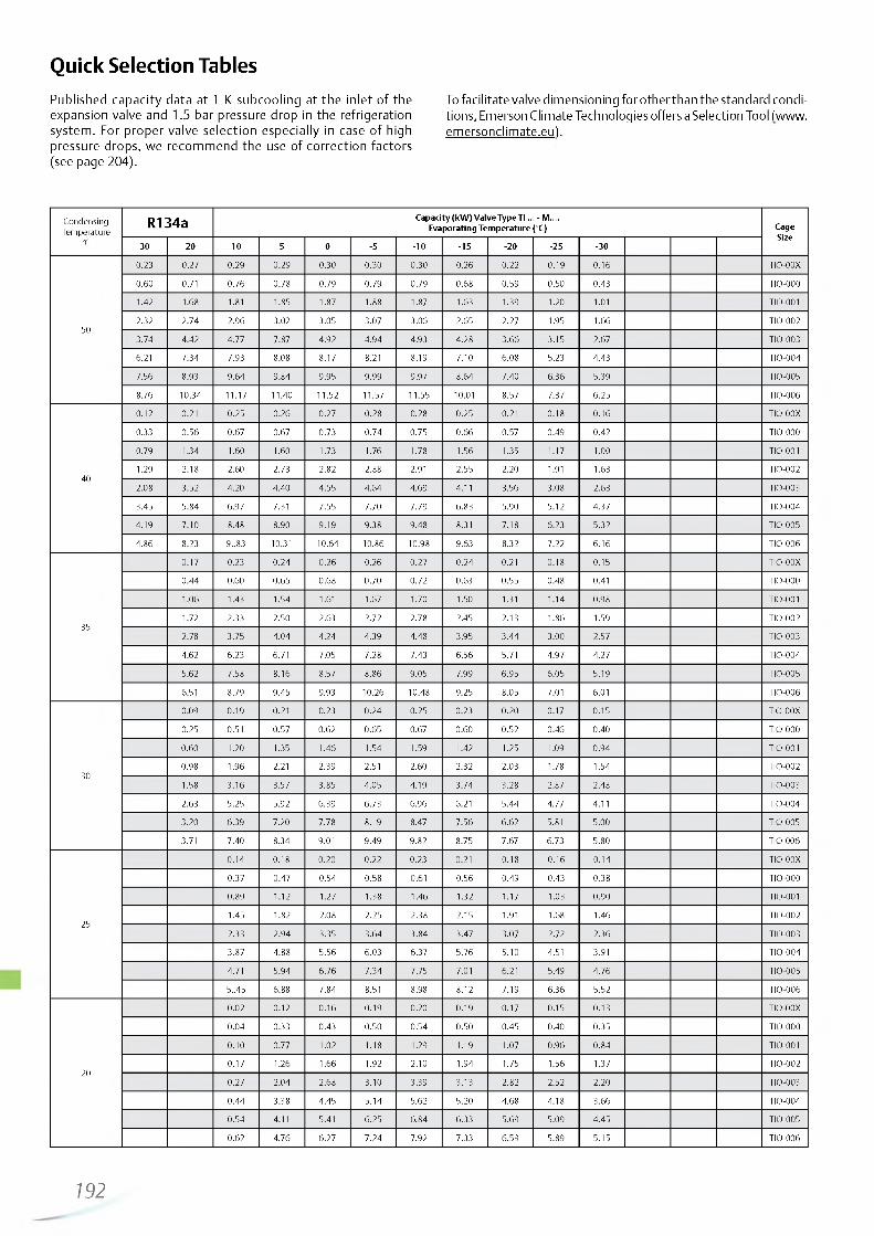
http://holodko.ru/
Quick Selection TablesPublished capacity data at 1 K subcooling at the inlet of the expansion valve and 1.5 bar pressure drop in the refrigeration system . For proper valve selection especially in case of high pressure drops, we recommend the use of correction factors (see page 204).
To facilitate valve dimensioning for other than the standard conditions, Emerson Climate Technologies offers a Selection Tool (www. emersonclimate.eu).
CondensingTemperature
°C
R134a Cap acity (kW ) V a lve Type TI ... - M.... Evaporating Tem perature (°C) Cage
Size30 20 10 5 0 -5 -1 0 -1 5 -20 -2 5 -30
50
0.23 0.27 0.29 0 .29 0.30 0 .30 0 .30 0 .26 0 .22 0 .19 0 .16 TIO-00X
0.60 0.71 0 .76 0 .78 0.79 0 .79 0 .79 0 .68 0 .59 0.50 0 .43 TIO-000
1.42 1.68 1.81 1.85 1.87 1.88 1.87 1.63 1.39 1.20 1.01 TIO-001
2.32 2 .74 2 .96 3.02 3 .05 3 .07 3 .06 2.65 2.27 1.95 1.66 TIO-002
3.74 4 .42 4.77 7.87 4 .92 4 .94 4.93 4 .28 3 .66 3.15 2.67 TIO-003
6.21 7 .34 7 .93 8.08 8.17 8.21 8.19 7 .10 6 .08 5.23 4 .43 TIO-004
7.56 8.93 9 .64 9 .84 9 .95 9 .99 9.97 8 .64 7 .40 6 .36 5.39 TIO-005
8.76 10.34 11.17 11.40 11.52 11.57 11.55 10.01 8.57 7.37 6 .25 TIO-006
40
0.12 0.21 0 .25 0 .26 0 .27 0 .28 0.28 0 .25 0.21 0 .18 0 .16 TIO-00X
0.33 0 .56 0 .67 0.67 0 .73 0 .74 0 .75 0 .66 0.57 0 .49 0 .42 TIO-000
0.79 1.34 1.60 1.60 1.73 1.76 1.78 1.56 1.35 1.17 1.00 TIO-001
1.29 2.18 2.60 2.73 2.82 2.88 2.91 2.55 2.20 1.91 1.63 TIO-002
2.08 3 .52 4.20 4 .40 4 .55 4 .64 4 .69 4.11 3 .56 3 .08 2.63 TIO-003
3 .45 5 .84 6.97 7.31 7 .55 7.70 7 .79 6 .83 5.90 5.12 4 .37 TIO-004
4 .19 7 .10 8.48 8.90 9 .19 9.38 9 .48 8.31 7.18 6 .23 5.32 TIO-005
4 .86 8.23 9 ..83 10.31 10.64 10.86 10.98 9 .63 8.32 7 .22 6 .16 TIO-006
35
0 .17 0.23 0 .24 0 .26 0 .26 0.27 0 .24 0.21 0 .18 0.15 TIO-00X
0 .44 0.60 0 .65 0 .68 0 .70 0 .72 0.63 0 .55 0 .48 0.41 TIO-000
1.06 1.43 1.54 1.61 1.67 1.70 1.50 1.31 1.14 0.98 TIO-001
1.72 2.33 2.50 2.63 2.72 2.78 2.45 2.13 1.86 1.59 TIO-002
2.78 3 .75 4 .04 4 .24 4 .39 4 .48 3.95 3 .44 3 .00 2.57 TIO-003
4.62 6 .23 6.71 7.05 7 .28 7 .43 6 .56 5.71 4 .97 4.27 TIO-004
5.62 7 .58 8 .16 8.57 8 .86 9 .05 7.99 6 .95 6 .05 5.19 TIO-005
6.51 8.79 9 .45 9.93 10.26 10.48 9.25 8.05 7.01 6.01 TIO-006
30
0.09 0 .19 0.21 0.23 0 .24 0 .25 0 .23 0 .20 0.17 0 .15 TIO-00X
0.25 0.51 0 .57 0 .62 0 .65 0.67 0 .60 0 .52 0 .46 0 .40 TIO-000
0.60 1.20 1.35 1.46 1.54 1.59 1.42 1.25 1.09 0 .94 TIO-001
0.98 1.96 2.21 2.39 2.51 2.60 2.32 2.03 1.78 1.54 TIO-002
1.58 3 .16 3.57 3 .85 4 .05 4.19 3 .74 3 .28 2.87 2.48 TIO-003
2.63 5.25 5.92 6 .39 6 .73 6 .96 6.21 5 .44 4.77 4.11 TIO-004
3.20 6 .39 7.20 7 .78 8.19 8.47 7 .56 6 .62 5.81 5.00 TIO-005
3.71 7 .40 8.34 9.01 9 .49 9 .82 8.75 7.67 6 .73 5.80 TIO-006
25
0 .14 0.18 0 .20 0 .22 0 .23 0.21 0 .18 0 .16 0 .14 TIO-00X
0.37 0 .47 0 .54 0 .58 0.61 0 .56 0 .49 0 .43 0 .38 TIO-000
0 .89 1.12 1.27 1.38 1.46 1.32 1.17 1.03 0 .90 TIO-001
1.45 1.82 2.08 2.25 2.38 2.15 1.91 1.68 1.46 TIO-002
2.33 2 .94 3.35 3 .64 3 .84 3 .47 3 .07 2.72 2 .36 TIO-003
3 .87 4 .88 5 .56 6 .03 6.37 5 .76 5.10 4.51 3.91 TIO-004
4.71 5 .94 6 .76 7 .34 7.75 7.01 6.21 5.49 4 .76 TIO-005
5..45 6.88 7 .84 8.51 8.98 8.12 7 .19 6 .36 5.52 TIO-006
20
0 .02 0.12 0 .16 0 .19 0.20 0 .19 0 .17 0.15 0 .13 TIO-00X
0 .04 0.33 0 .43 0 .50 0 .54 0 .50 0 .45 0.40 0 .35 TIO-000
0.10 0.77 1.02 1.18 1.29 1.19 1.07 0.96 0 .84 TIO-001
0.17 1.26 1.66 1.92 2.10 1.94 1.75 1.56 1.37 TIO-002
0 .27 2.04 2.68 3 .10 3.39 3 .13 2.82 2.52 2.20 TIO-003
0 .44 3.38 4 .45 5 .14 5.62 5.20 4 .68 4.18 3 .66 TIO-004
0 .54 4.11 5.41 6 .25 6 .84 6 .33 5.69 5.09 4 .45 TIO-005
0.62 4 .76 6 .27 7 .24 7.92 7 .33 6 .59 5.89 5.15 TIO-006
192
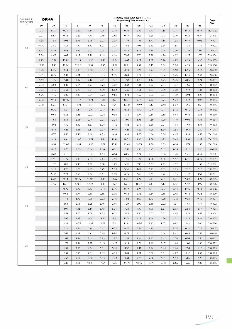
http://holodko.ru/
CondensingTemperature
R404A Cap acity (kW ) V a lve Type TI ... - S.... Evaporating Tem perature (°C) Cage
Size°C 30 20 10 5 0 -5 -1 0 -1 5 -20 -2 5 -30 -3 5 -40 -45
0.27 0.32 0 .34 0 .35 0 .35 0 .35 0 .34 0.30 0 .25 0 .22 0 .18 0 .15 0.13 0.10 TIO-00X
0.71 0.82 0 .88 0 .89 0 .89 0 .89 0.88 0.77 0 .65 0 .56 0 .47 0.39 0.33 0.27 TIO-000
1.65 1.91 2 .04 2.07 2.08 2.07 2.05 1.80 1.53 1.30 1.10 0.92 0 .76 0 .62 TIO-001
5050.00 2.82 3 .28 3 .50 3 .55 3.57 3.55 3 .52 3 .08 2.62 2 .24 1.88 1.58 1.30 TIO-002
4.47 5.19 5 .54 5.62 5.65 5.63 5.57 4.88 4 .14 3 .54 2.98 2.50 2 .06 1.69 TIO-003
7.29 8.47 9 .05 9.17 9.21 9 .18 9 .09 7 .96 6 .76 5.78 4 .86 4 .07 3 .37 2 .76 TIO-004
8.85 10.29 10.99 11.15 11.20 11.16 11.04 9.67 8.22 7.02 5.90 4 .95 4 .09 3 .36 TIO-005
10.26 11.93 12.74 12.92 12.98 12.93 12.80 11.21 9.53 8.13 6 .84 5 .74 4 .75 3 .89 TIO-006
0.20 0 .29 0 .34 0 .35 0 .36 0.37 0 .37 0.33 0.28 0 .24 0.21 0 .18 0 .15 0.12 TIO-00X
0.51 0.75 0.87 0.91 0 .93 0 .95 0 .95 0 .84 0.73 0 .63 0 .54 0 .46 0 .38 0.32 TIO-000
1.19 1.75 2 .04 2.12 2.18 2.21 2.22 1.97 1.70 1.47 1.25 1.06 0.89 0 .74 TIO-001
402.03 3 .00 3 .49 3 .64 3 .73 3.78 3.80 3 .38 2.91 2.52 2 .14 1.82 1.53 1.27 TIO-002
3.22 4 .76 5.53 5 .76 5.91 5.99 6 .02 5.35 4.61 3 .99 3.39 2.88 2.42 2.01 TIO-003
5.25 7 .76 9 .02 9 .40 9 .64 9.78 9 .83 8.73 7 .52 6 .50 5.54 4 .70 3 .94 3 .28 TIO-004
6 .38 9 .43 10.96 11.42 11.71 11.88 11.94 10.61 9 .14 7.90 6.73 5.71 4.79 3 .98 TIO-005
7 .40 10.93 12.71 13.23 13.58 13.77 13.84 12.30 10.59 9 .16 7 .80 6 .62 5.55 4 .62 TIO-006
0 .25 0.32 0 .34 0 .36 0 .37 0 .37 0 .33 0.29 0.25 0.21 0 .18 0 .15 0 .13 TIO-00X
0 .65 0.83 0 .88 0 .92 0 .94 0 .95 0.85 0 .74 0 .64 0 .55 0 .47 0.40 0.33 TIO-000
1.53 1.93 2 .06 2 .14 2.20 2.23 1.99 1.73 1.50 1.29 1.10 0 .93 0.77 TIO-001
352.62 3 .32 3 .52 3 .67 3 .76 3.82 3.42 2 .96 2.58 2.21 1.88 1.59 1.33 TIO-002
4.15 5.25 5.58 5.81 5 .96 6.05 5.41 4 .69 4 .08 3 .50 2.98 2.51 2.10 TIO-003
6.77 8.56 9 .10 9 .48 9.72 9 .86 8.83 7 .65 6 .66 5.70 4.87 4.10 3 .43 TIO-004
8.22 10.41 11.06 11.51 11.81 11.98 10.73 9 .30 8.09 6.93 5.92 4 .99 4 .17 TIO-005
9.53 12.06 12.82 13.35 13.69 13.89 12.44 10.78 9 .38 8.03 6 .86 5.78 4 .83 TIO-006
0.19 0 .29 0 .32 0 .34 0 .36 0 .36 0 .33 0 .29 0.25 0.22 0 .19 0 .16 0 .13 TIO-00X
0.49 0 .75 0.83 0.88 0.91 0 .94 0.85 0 .74 0 .65 0 .56 0 .48 0.41 0 .34 TIO-000
1.15 1.75 1.93 2.05 2.13 2.19 1.98 1.73 1.51 1.30 1.12 0.95 0.79 TIO-001
301.97 3.01 3 .30 3.51 3 .66 3.75 3.39 2 .96 2.59 2.23 1.92 1.62 1.36 TIO-002
3.13 4 .76 5.23 5 .56 5.79 5.94 5 .36 4 .69 4 .10 3 .53 3.03 2.57 2 .16 TIO-003
5.10 7 .77 8.53 9 .07 9 .44 9.69 8.75 7 .65 6 .70 5.77 4.95 4 .19 3 .52 TIO-004
6.20 9 .44 10.36 11.02 11.48 11.77 10.63 9 .29 8 .14 7.01 6.01 5.09 4 .27 TIO-005
7.18 10.94 12.01 12.77 13.30 13.65 12.33 10.77 9.43 8.12 6.97 5.90 4 .95 TIO-006
0.25 0 .29 0.32 0 .34 0 .35 0 .32 0 .28 0.25 0.22 0 .19 0 .16 0 .13 TIO-00X
0.63 0 .74 0.81 0 .86 0 .90 0 .82 0 .73 0 .64 0 .55 0 .48 0.41 0 .34 TIO-000
1.48 1.72 1.90 2.02 2.10 1.92 1.69 1.49 1.29 1.12 0 .95 0 .80 TIO-001
252.53 2.95 3 .25 3 .46 3 .60 3 .29 2.90 2 .56 2.22 1.91 1.63 1.37 TIO-002
4.01 4 .68 5 .14 5.48 5.71 5.21 4.60 4 .06 3.51 3 .03 2.58 2.17 TIO-003
6.54 7 .63 8.39 8 .94 9.31 8.51 7 .50 6 .62 5.73 4 .95 4.21 3.55 TIO-004
7 .95 9.27 10.20 10.86 11.31 10.34 9.11 8 .04 6 .96 6.01 5.11 4.31 TIO-005
9.22 10.75 11.82 12.59 13.11 11.98 10.56 9 .32 8.07 6.97 5.93 5.00 TIO-006
0 .17 0 .24 0 .28 0.31 0.33 0 .30 0 .27 0 .24 0.21 0.18 0 .16 0 .13 TIO-00X
0 .44 0.61 0 .72 0.79 0 .84 0 .78 0 .70 0 .62 0 .54 0.47 0.40 0 .34 TIO-000
1.04 1.42 1.67 1.85 1.97 1.83 1.63 1.45 1.27 1.10 0 .94 0 .80 TIO-001
201.78 2.44 2.87 3 .16 3 .37 3 .13 2.79 2.49 2.17 1.88 1.61 1.36 TIO-002
2.82 3 .86 4 .54 5.01 5 .34 4 .96 4.42 3 .94 3 .44 2.98 2.55 2 .16 TIO-003
4.59 6.30 7.41 8.17 8.71 8.09 7.21 6.42 5.61 4 .87 4 .16 3 .53 TIO-004
5.58 7 .66 9 .00 9 .93 10.58 9.83 8.76 7 .80 6.81 5.91 5 .06 4.28 TIO-005
6.47 8.88 10.43 11.51 12.27 11.39 10.16 9 .05 7 .90 6 .86 5 .86 4.97 TIO-006
193

http://holodko.ru/
Condensing dew point
Temperature bubble point
R407C C ap acity (kW ) V alve Type TI ... - N.... Evaporating Tem perature (°C) Cage Size
°C °C 20 10 5 0 -5 -1 0 -1 5 -20 -2 5
0.49 0 .52 0 .52 0 .53 0 .53 0.53 0 .46 0.38 0 .32 TIO-00X
1.27 1.34 1.36 1.37 1.37 1.36 1.19 1.00 0 .83 TIO-000
3 .17 3 .35 3 .39 3.42 3 .42 3.41 2.99 2.49 2.07 TIO-001
54 505.16 5.45 5.53 5.57 5.57 5.55 4 .86 4 .06 3.37 TIO-002
8.33 8.80 8.92 8.98 9 .00 8 .96 7.85 6 .55 5.44 TIO-003
13.58 14.35 14.55 14.65 14.67 14.61 12.80 10.69 8.87 TIO-004
16.57 17.50 17.75 17.87 17.89 17.82 15.61 13.04 10.82 TIO-005
19.11 20.18 20.46 20.60 20.63 20.55 18.00 15.03 12.47 TIO-006
0 .44 0 .49 0.51 0 .52 0.53 0 .53 0 .47 0.39 0 .33 TIO-00X
1.14 1.28 1.32 1.34 1.36 1.37 1.21 1.02 0 .85 TIO-000
2.86 3 .19 3.29 3 .36 3 .40 3 .42 3 .02 2.54 2.13 TIO-001
45 404.66 5.19 5 .36 5.47 5 .54 5.58 4 .93 4 .14 3 .46 TIO-002
7.52 8.38 8.65 8.83 8.95 9.00 7 .95 6 .69 5.59 TIO-003
12.25 13.66 14.10 14.40 14.58 14.67 12.96 10.91 9.11 TIO-004
14.95 16.67 17.20 17.57 17.79 17.90 15.82 13.31 11.12 TIO-005
17.24 19.22 19.83 20.25 20.52 20.64 18.24 15.34 12.82 TIO-006
0.40 0.47 0.49 0 .50 0.51 0 .52 0 .46 0 .39 0.33 TIO-00X
1.03 1.21 1.26 1.30 1.33 1.34 1.19 1.01 0.85 TIO-000
2.58 3 .02 3 .15 3 .25 3.32 3 .36 2.99 2.52 2.12 TIO-001
40 354.20 4.91 5.14 5.30 5.41 5.47 4 .86 4.11 3 .45 TIO-002
6.78 7 .93 8.29 8.55 8.73 8 .84 7 .85 6.63 5 .56 TIO-003
11.06 12.93 13.52 13.94 14.23 14.41 12.79 10.81 9.07 TIO-004
13.49 15.77 16.49 17.01 17.36 17.58 15.61 13.19 11.06 TIO-005
15.56 18.19 19.02 19.61 20.02 20.27 18.00 15.21 12.75 TIO-006
0 .34 0 .43 0 .46 0.48 0 .49 0.50 0 .45 0 .38 0 .32 TIO-00X
0.88 1.11 1.18 1.24 1.28 1.30 1.16 0 .99 0 .83 TIO-000
2.19 2.78 2 .96 3.09 3 .19 3 .25 2.91 2.47 2.08 TIO-001
35 303.57 4.53 4 .82 5 .04 5.20 5.30 4 .74 4 .02 3.39 TIO-002
5 .76 7.30 7 .78 8.13 8.39 8 .56 7 .64 6 .49 5.47 TIO-003
9.39 11.91 12.69 13.26 13.67 13.95 12.46 10.58 8.92 TIO-004
11.46 14.53 15.48 16.18 16.68 17.02 15.21 12.91 10.88 TIO-005
13.22 16.75 17.85 18.66 19.23 19.62 17.53 14.89 12.54 TIO-006
0.38 0.42 0 .44 0 .46 0 .48 0 .43 0.37 0.31 TIO-00X
0.98 1.08 1.15 1.21 1.24 1.12 0 .96 0.81 TIO-000
2.46 2.70 2.88 3.01 3.11 2.80 2.39 2.02 TIO-001
30 254.01 4 .40 4 .70 4.91 5.06 4 .55 3.89 3 .29 TIO-002
6.47 7.11 7.58 7 .92 8.16 7 .35 6 .28 5.32 TIO-003
10.55 11.59 12.36 12.91 13.31 11.98 10.24 8.67 TIO-004
12.87 14.14 15.07 15.75 16.24 14.62 12.49 10.58 TIO-005
14.84 16.31 17.38 18.17 18.72 16.86 14.40 12.19 TIO-006
0.37 0.40 0 .43 0.45 0.41 0 .35 0 .30 TIO-00X
0.95 1.04 1.11 1.16 1.06 0.91 0 .78 TIO-000
2.37 2.61 2.78 2.91 2.65 2.28 1.94 TIO-001
26 203 .86 4.25 4 .54 4 .74 4.31 3.71 3 .16 TIO-002
6.23 6 .86 7 .32 7 .65 6 .96 6 .00 5.11 TIO-003
10.16 11.19 11.93 12.47 11.35 9.77 8.33 TIO-004
12.40 13.65 14.56 15.22 13.85 11.92 10.16 TIO-005
14.30 15.74 16.79 17.55 15.97 13.75 11.71 TIO-006
194
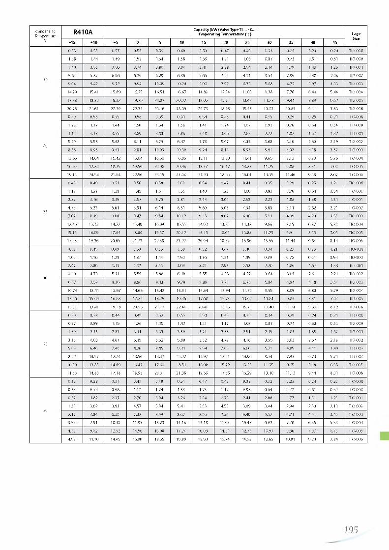
http://holodko.ru/
CondensingTemperature
R410A Cap acity (kW ) V alve Type TI ... - Z.... Evaporating Tem perature (°C) Cage
Size°C + 1 5 + 10 +5 0 -5 -10 -1 5 -20 -2 5 -30 -3 5 -40 -45
0 .53 0 .55 0.57 0 .58 0.59 0.60 0 .53 0 .47 0 .40 0 .33 0.28 0.23 0 .20 TIO-00X
1.38 1.44 1.49 1.52 1.54 1.56 1.39 1.21 1.03 0 .87 0 .73 0.61 0.51 TIO-000
3 .40 3 .55 3 .66 3 .74 3 .80 3 .84 3.41 2.98 2 .54 2 .14 1.79 1.49 1.25 TIO-001
505.64 5.87 6 .06 6 .20 6 .29 6 .36 5.65 4 .94 4.21 3 .54 2 .96 2.48 2.08 TIO-002
9 .04 9.42 9 .72 9 .94 10.09 10.20 9 .06 7.92 6 .75 5.68 4 .75 3.97 3 .33 TIO-003
14.79 15.41 15.89 16.25 16.51 16.67 14.82 12.94 11.03 9 .28 7 .76 6 .49 5 .44 TIO-004
17.98 18.73 19.32 19.76 20.07 20.27 18.02 15.74 13.42 11.28 9 .44 7 .89 6 .62 TIO-005
20.75 21.61 22.29 22.79 23.16 23.39 20.79 18.16 15.48 13.02 10.89 9.11 7 .63 TIO-006
0.49 0 .53 0.55 0.58 0 .59 0.61 0 .54 0 .48 0.41 0.35 0 .29 0 .25 0.21 TIO-00X
1.28 1.37 1.44 1.50 1.54 1.58 1.41 1.24 1.07 0.90 0 .76 0 .64 0 .54 TIO-000
3 .14 3 .37 3 .55 3.69 3.80 3 .88 3 .48 3 .06 2.63 2.22 1.87 1.57 1.32 TIO-001
405.20 5.58 5.88 6.11 6.29 6 .42 5 .76 5.07 4 .35 3 .68 3.10 2.60 2.19 TIO-002
8.35 8.95 9 .43 9.81 10.09 10.30 9 .24 8.13 6 .98 5.91 4 .97 4.18 3.52 TIO-003
13.65 14.64 15.42 16.04 16.50 16.85 15.11 13.30 11.41 9 .66 8.13 6.83 5.76 TIO-004
16.60 17.80 18.75 19.50 20.06 20.48 18.37 16.17 13.88 11.75 9 .88 8.31 7.00 TIO-005
19.15 20.54 21.64 22.50 23.15 23.64 21.20 18.66 16.01 13.55 11.40 9 .58 8.07 TIO-006
0.45 0 .49 0 .53 0 .56 0 .58 0 .60 0 .54 0.47 0.41 0 .35 0 .29 0 .25 0.21 TIO-00X
1.17 1.28 1.38 1.45 1.51 1.55 1.40 1.23 1.06 0 .90 0 .76 0 .64 0 .54 TIO-000
2.87 3 .16 3.39 3 .57 3 .70 3.81 3 .44 3 .04 2.62 2.22 1.88 1.58 1.34 TIO-001
354 .75 5.23 5.61 5.91 6 .14 6.31 5.69 5.03 4 .34 3.68 3.11 2.62 2.21 TIO-002
7 .62 8.39 9.00 9.47 9 .84 10.12 9 .13 8.07 6 .96 5.91 4 .99 4 .20 3 .55 TIO-003
12.46 13.73 14.72 15.49 16.09 16.55 14.93 13.20 11.38 9 .66 8.15 6 .87 5.80 TIO-004
15.15 16.69 17.89 18.84 19.57 20.12 18.15 16.05 13.83 11.75 9.91 8.35 7 .05 TIO-005
17.48 19.26 20.65 21.73 22.58 23.22 20.94 18.52 15.96 13.55 11.44 9 .64 8 .14 TIO-006
0 .39 0 .45 0 .49 0 .53 0.55 0.58 0 .52 0 .47 0 .40 0 .34 0 .29 0.25 0.21 TIO-00X
1.00 1.16 1.28 1.37 1.44 1.50 1.36 1.21 1.05 0 .89 0 .76 0 .64 0 .54 TIO-000
2.47 2 .86 3 .15 3 .37 3 .55 3.69 3.35 2.98 2.58 2.20 1.86 1.57 1.33 TIO-001
304 .10 4 .73 5.21 5.59 5.88 6.10 5.55 4 .93 4 .27 3 .64 3.08 2.61 2.21 TIO-002
6 .57 7 .59 8 .36 8 .96 9.43 9.79 8.89 7.91 6 .85 5 .84 4 .94 4.18 3 .54 TIO-003
10.74 12.41 13.67 14.66 15.42 16.01 14.54 12.94 11.20 9 .55 8.09 6 .83 5.79 TIO-004
13.06 15.09 16.63 17.82 18.75 19.46 17.68 15.73 13.62 11.61 9 .83 8.31 7 .04 TIO-005
15.07 17.41 19.18 20.56 21.63 22.46 20.40 18.15 15.71 13.40 11.34 9 .59 8.12 TIO-006
0.30 0.38 0 .44 0 .49 0 .52 0 .55 0.50 0.45 0 .39 0 .34 0 .29 0 .24 0.21 TIO-00X
0.77 0.99 1.15 1.26 1.35 1.42 1.31 1.17 1.02 0 .87 0 .74 0 .63 0 .53 TIO-000
1.89 2.43 2.82 3.11 3 .33 3 .50 3.21 2.88 2.51 2.15 1.83 1.55 1.32 TIO-001
253.13 4 .03 4.67 5.15 5.52 5.80 5.32 4 .77 4 .16 3 .56 3 .03 2.57 2.18 TIO-002
5.03 6 .46 7.49 8.26 8.85 9.31 8 .54 7 .65 6 .66 5.71 4.85 4.11 3 .49 TIO-003
8.22 10.57 12.24 13.50 14.47 15.22 13.97 12.51 10.90 9 .34 7.93 6 .73 5.71 TIO-004
10.00 12.85 14.89 16.42 17.60 18.51 16.98 15.22 13.25 11.35 9.65 8.18 6 .95 TIO-005
11.53 14.83 17.18 18.95 20.31 21.36 19.59 17.56 15.29 13.10 11.13 9 .44 8.01 TIO-006
0.13 0 .28 0 .37 0 .43 0.48 0.51 0 .47 0 .43 0 .38 0 .32 0 .28 0 .24 0.20 TIO-00X
0.33 0 .74 0 .96 1.12 1.24 1.33 1.23 1.12 0 .98 0 .84 0 .72 0.61 0.52 TIO-000
0.82 1.82 2.37 2 .76 3 .04 3 .26 3 .04 2.75 2.41 2.08 1.77 1.51 1.29 TIO-001
201.35 3 .02 3 .93 4 .57 5 .04 5.41 5.03 4.55 3 .99 3 .44 2 .94 2.50 2.13 TIO-002
2.17 4 .84 6 .30 7 .32 8.09 8.67 8 .06 7.30 6.40 5.52 4.71 4.01 3 .42 TIO-003
3 .55 7.91 10.30 11.98 13.23 14.18 13.18 11.93 10.47 9 .02 7 .70 6 .56 5.59 TIO-004
4 .32 9.62 12.52 14.56 16.08 17.24 16.03 14.51 12.73 10.97 9 .36 7 .97 6 .79 TIO-005
4 .98 11.10 14.45 16.80 18.55 19.89 18.50 16.74 14.68 12.65 10.81 9 .20 7 .84 TIO-006
195
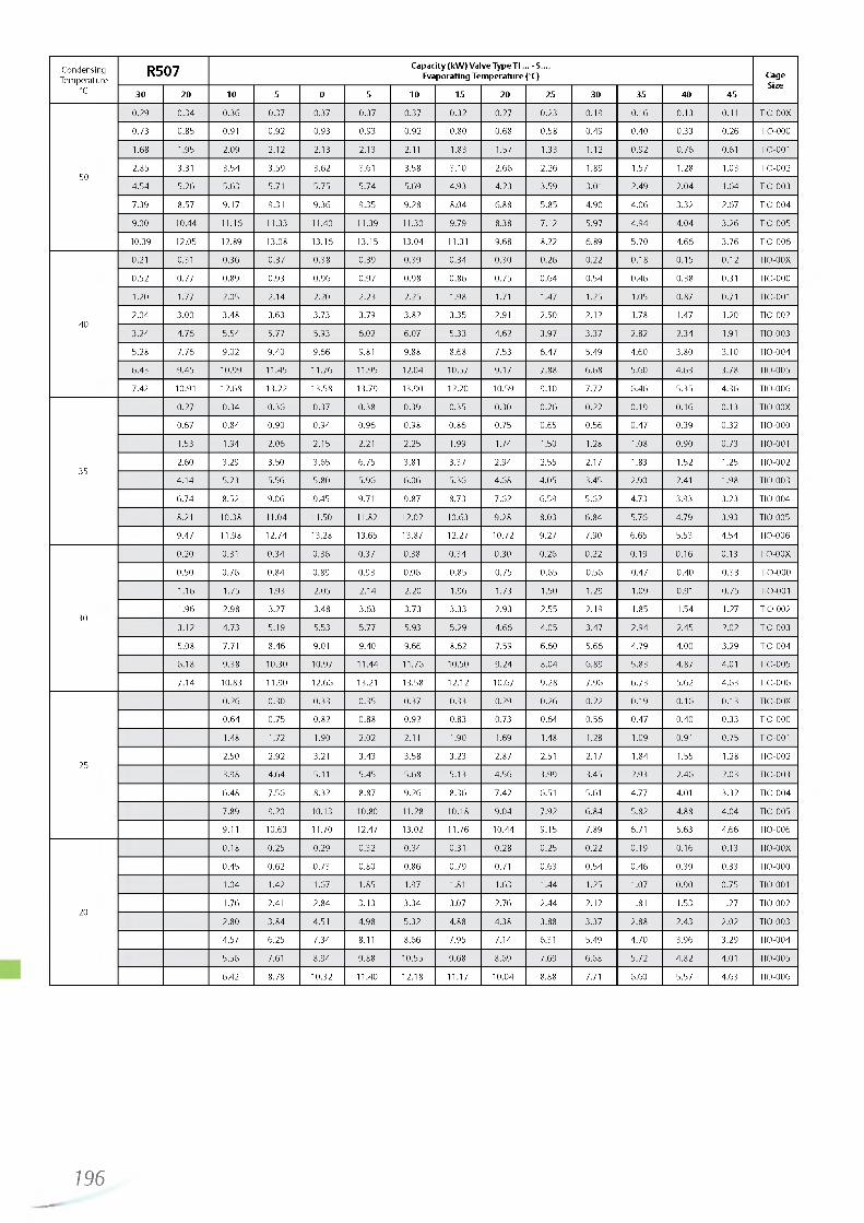
http://holodko.ru/
CondensingTemperature
R507 C ap acity (kW ) V alve Type TI ... - S . . Evaporating Tem perature (°C) Cage
Size°C 30 20 10 5 0 -5 -1 0 -1 5 -20 -2 5 -30 -3 5 -40 -45
0.29 0 .34 0 .36 0.37 0.37 0 .37 0 .37 0 .32 0 .27 0 .23 0 .19 0 .16 0.13 0.11 TIO-00X
0.73 0 .85 0.91 0 .92 0.93 0.93 0 .92 0 .80 0 .68 0 .58 0 .49 0 .40 0.33 0 .26 TIO-000
1.68 1.95 2.09 2.12 2.13 2.13 2.11 1.83 1.57 1.33 1.12 0 .92 0 .76 0.61 TIO-001
502.85 3.31 3 .54 3 .59 3 .62 3.61 3.58 3.10 2 .66 2 .26 1.89 1.57 1.28 1.03 TIO-002
4 .54 5 .26 5.63 5.71 5.75 5 .74 5.69 4.93 4 .23 3 .59 3.01 2.49 2 .04 1.64 TIO-003
7.39 8.57 9 .17 9.31 9 .36 9 .35 9 .28 8.04 6.88 5.85 4 .90 4 .06 3 .32 2.67 TIO-004
9.00 10.44 11.16 11.33 11.40 11.39 11.30 9.79 8.38 7.12 5.97 4 .94 4 .04 3 .26 TIO-005
10.39 12.05 12.89 13.08 13.16 13.15 13.04 11.31 9.68 8.22 6.89 5.70 4 .66 3 .76 TIO-006
0.21 0.31 0 .36 0 .37 0 .38 0 .39 0 .39 0 .34 0 .30 0 .26 0.22 0 .18 0 .15 0 .12 TIO-00X
0 .52 0 .77 0.89 0.93 0 .96 0 .97 0 .98 0 .86 0 .75 0 .64 0 .54 0 .46 0 .38 0.31 TIO-000
1.20 1.77 2.05 2.14 2.20 2.23 2.25 1.98 1.71 1.47 1.25 1.05 0.87 0.71 TIO-001
402.04 3 .00 3 .48 3.63 3.73 3.79 3 .82 3 .35 2.91 2.50 2.12 1.78 1.47 1.20 TIO-002
3 .24 4 .76 5 .54 5.77 5.93 6.02 6.07 5.33 4 .62 3 .97 3 .37 2.82 2.34 1.91 TIO-003
5.28 7 .76 9 .02 9 .40 9 .66 9.81 9.88 8.68 7 .53 6 .47 5.49 4 .60 3 .80 3.10 TIO-004
6 .43 9 .45 10.99 11.45 11.76 11.95 12.04 10.57 9 .17 7 .88 6 .68 5.60 4 .63 3 .78 TIO-005
7.42 10.91 12.68 13.22 13.58 13.79 13.90 12.20 10.59 9 .10 7 .72 6 .46 5.35 4 .36 TIO-006
0 .27 0 .34 0 .36 0 .37 0 .38 0 .39 0.35 0.30 0 .26 0 .22 0 .19 0 .16 0 .13 TIO-00X
0.67 0 .84 0 .90 0 .94 0 .96 0 .98 0 .86 0.75 0.65 0 .56 0 .47 0 .39 0 .32 TIO-000
1.53 1.94 2 .06 2.15 2.21 2.25 1.99 1.74 1.50 1.28 1.08 0 .90 0 .73 TIO-001
352.60 3.29 3.50 3 .65 6 .75 3.81 3 .37 2 .94 2.55 2.17 1.83 1.52 1.25 TIO-002
4 .14 5.23 5.56 5.80 5 .96 6 .06 5 .36 4 .68 4 .05 3.45 2.90 2.41 1.98 TIO-003
6 .74 8.52 9 .06 9.45 9.71 9 .87 8.73 7 .62 6 .59 5.62 4.73 3.93 3 .23 TIO-004
8.21 10.38 11.04 11.50 11.82 12.02 10.63 9 .28 8.03 6 .84 5.76 4.79 3.93 TIO-005
9.47 11.98 12.74 13.28 13.65 13.87 12.27 10.72 9 .27 7 .90 6 .65 5.53 4 .54 TIO-006
0.20 0.31 0 .34 0 .36 0.37 0.38 0 .34 0 .30 0 .26 0 .22 0 .19 0 .16 0.13 TIO-00X
0.50 0 .76 0 .84 0 .89 0.93 0 .96 0 .85 0 .75 0 .65 0 .56 0.47 0 .40 0 .33 TIO-000
1.16 1.75 1.93 2.05 2 .14 2.20 1.96 1.73 1.50 1.29 1.09 0.91 0 .75 TIO-001
301.96 2.98 3.27 3.48 3.63 3 .73 3 .33 2.93 2.55 2.19 1.85 1.54 1.27 TIO-002
3.12 4 .73 5.19 5.53 5.77 5.93 5.29 4 .66 4 .05 3 .47 2 .94 2.45 2.02 TIO-003
5.08 7.71 8 .46 9.01 9.40 9 .66 8.62 7 .59 6 .60 5 .66 4 .79 4 .00 3.29 TIO-004
6.18 9 .38 10.30 10.97 11.44 11.76 10.50 9 .24 8 .04 6 .89 5.83 4 .87 4.01 TIO-005
7 .14 10.83 11.90 12.66 13.21 13.58 12.12 10.67 9 .28 7 .96 6 .73 5.62 4 .63 TIO-006
0 .26 0 .30 0 .33 0 .35 0 .37 0.33 0.29 0 .26 0 .22 0 .19 0 .16 0 .13 TIO-00X
0 .64 0 .75 0 .82 0 .88 0 .92 0.83 0.73 0 .64 0 .56 0 .47 0 .40 0 .33 TIO-000
1.48 1.72 1.90 2.02 2.11 1.90 1.69 1.48 1.28 1.09 0.91 0 .75 TIO-001
252.50 2.92 3.21 3 .43 3 .58 3 .23 2.87 2.51 2.17 1.84 1.55 1.28 TIO-002
3.98 4 .64 5.11 5.45 5.68 5.13 4 .56 3 .99 3.45 2.93 2 .46 2.03 TIO-003
6 .48 7 .56 8.32 8.87 9 .26 8 .36 7 .42 6.51 5.61 4.77 4.01 3 .32 TIO-004
7 .89 9.20 10.13 10.80 11.28 10.18 9 .04 7 .92 6 .84 5.82 4.88 4 .04 TIO-005
9.11 10.63 11.70 12.47 13.02 11.76 10.44 9 .15 7 .89 6.71 5.63 4 .66 TIO-006
0 .18 0 .25 0.29 0.32 0 .34 0.31 0 .28 0 .25 0 .22 0 .19 0 .16 0.13 TIO-00X
0 .45 0 .62 0 .73 0.80 0 .86 0 .79 0.71 0 .63 0 .54 0 .46 0 .39 0.33 TIO-000
1.04 1.42 1.67 1.85 1.97 1.81 1.63 1.44 1.25 1.07 0 .90 0 .75 TIO-001
201.76 2.41 2 .84 3 .13 3 .34 3.07 2.76 2 .44 2.12 1.81 1.53 1.27 TIO-002
2.80 3 .84 4.51 4 .98 5.32 4.88 4.38 3.88 3 .37 2.88 2.43 2.02 TIO-003
4.57 6 .25 7 .34 8.11 8 .66 7 .95 7 .14 6.31 5.49 4 .70 3 .96 3 .29 TIO-004
5.56 7.61 8 .94 9 .88 10.55 9 .68 8.69 7.69 6.68 5.72 4 .82 4.01 TIO-005
6.42 8.78 10.32 11.40 12.18 11.17 10.04 8.88 7.71 6.60 5.57 4 .63 TIO-006
196—

http://holodko.ru/
CondensingTemperature
R22 C ap acity (kW ) V alve Type TI ... - H .... Evaporating Tem perature (°C) Cage
Size°C 30 20 10 5 0 -5 -1 0 -1 5 -20 -2 5 -30 -3 5 -40 -45
0.38 0.45 0.50 0.51 0 .52 0 .53 0 .53 0 .46 0.41 0.35 0.30 0 .26 0 .22 0 .19 TIO-00X
0.98 1.17 1.29 1.33 1.35 1.38 1.36 1.20 1.05 0.91 0.78 0 .66 0.57 0 .48 TIO-000
2.40 2 .86 3 .16 3 .26 3.32 3 .39 3 .33 2.95 2.58 2 .24 1.91 1.62 1.40 1.19 TIO-001
504.03 4 .78 5.29 4.47 5.56 5.67 5.57 4 .95 4 .32 3 .75 3 .20 2.72 2.35 2.00 TIO-002
6.41 7 .64 8.42 8.70 8.85 9.03 8.87 7 .88 6 .87 5.97 5.10 4 .34 3.45 3.18 TIO-003
10.50 12.51 13.79 14.26 14.50 14.80 14.53 12.90 11.26 9 .79 8.35 7 .10 6 .14 5.21 TIO-004
12.80 15.24 16.81 17.37 17.67 18.03 17.70 15.72 13.72 11.93 10.18 8 .66 7 .49 6 .35 TIO-005
14.76 17.58 19.38 20.04 20.38 20.79 20.42 18.14 15.82 13.76 11.74 9 .98 8 .64 7 .32 TIO-006
0.24 0.37 0 .44 0 .46 0 .48 0 .50 0 .49 0 .44 0.39 0 .34 0 .29 0 .25 0 .22 0 .18 TIO-00X
0.61 0.95 1.14 1.20 1.25 1.29 1.27 1.15 1.01 0.88 0 .75 0 .64 0 .56 0 .47 TIO-000
1.51 2.33 2.78 2 .94 3 .07 3 .17 3 .12 2.82 2.47 2.16 1.85 1.58 1.38 1.17 TIO-001
402.52 3 .90 4 .66 4.92 5.13 5.30 5.23 4 .73 4 .14 3 .62 3.10 2.65 2.31 1.96 TIO-002
4 .02 6.21 7.42 7 .84 8.18 8 .44 8.33 7 .53 6 .59 5 .76 4 .94 4.23 3.68 3 .12 TIO-003
6 .59 10.17 12.16 12.85 13.39 13.83 13.65 12.33 10.79 9 .44 8.10 6.92 6.03 5.12 TIO-004
8.03 12.40 14.82 15.65 16.32 16.85 16.63 15.03 13.15 11.50 9 .87 8 .44 7.35 6.23 TIO-005
9 .26 14.30 17.09 18.05 18.82 19.43 19.18 17.33 15.17 13.26 11.38 9 .73 8.48 7.19 TIO-006
0 .30 0 .40 0 .43 0 .45 0.47 0.48 0 .43 0 .38 0 .33 0 .29 0 .24 0.21 0.18 TIO-00X
0 .79 1.03 1.11 1.17 1.22 1.23 1.11 0 .98 0 .85 0 .74 0 .63 0 .55 0 .47 TIO-000
1.93 2.53 2.72 2.88 3 .00 3.01 2.71 2.40 2.09 1.81 1.55 1.35 1.15 TIO-001
353 .24 4 .23 4 .56 4 .82 5.02 5.03 4 .54 4.02 3.50 3 .03 2.60 2.27 1.93 TIO-002
5.16 6 .74 7 .27 7 .68 8.00 8.01 7 .23 6.40 5.57 4 .83 4 .14 3.61 3 .07 TIO-003
8.45 11.04 11.90 12.58 13.11 13.13 11.85 10.49 9.13 7.92 6 .78 5.92 5.03 TIO-004
10.30 13.46 14.50 15.32 15.97 16.00 14.44 12.78 11.12 9.65 8.27 7.21 6 .13 TIO-005
11.87 15.52 16.73 17.67 18.42 18.45 16.65 14.74 12.83 11.13 9.53 8.32 7 .07 TIO-006
0.21 0 .34 0.38 0.41 0 .44 0 .44 0.41 0 .36 0.31 0 .27 0 .24 0.21 0 .18 TIO-00X
0.55 0 .89 0.99 1.07 1.13 1.15 1.05 0.93 0.81 0 .70 0.61 0 .53 0 .46 TIO-000
1.35 2.19 2 .44 2.63 2.78 2.81 2.57 2.29 1.99 1.72 1.50 1.31 1.12 TIO-001
302.26 3.67 4.09 4.41 4 .66 4.71 4 .30 3 .83 3.33 2.88 2.52 2.20 1.88 TIO-002
3.59 5.84 6.51 7.02 7 .42 7 .50 6 .84 6 .10 5.30 4.59 4.01 3.51 2.99 TIO-003
5.89 9 .56 10.66 11.50 12.16 12.28 11.21 10.00 8.68 7.51 6.57 5.75 4 .90 TIO-004
7.18 11.65 12.99 14.02 14.81 14.97 13.66 12.18 10.58 9 .16 8.01 7.01 5.98 TIO-005
8.28 13.44 14.98 16.16 17.08 17.26 15.76 14.05 12.20 10.56 9 .24 8.08 6.89 TIO-006
0.28 0 .33 0 .38 0.40 0.41 0 .38 0 .34 0 .30 0 .26 0 .23 0 .20 0.17 TIO-00X
0.71 0 .85 0 .97 1.04 1.07 0.98 0 .88 0 .78 0 .68 0 .59 0.51 0 .44 TIO-000
1.76 2.10 2.37 2 .56 2.62 2.40 2 .16 1.91 1.67 1.44 1.26 1.08 TIO-001
252.94 3.51 3 .97 4 .29 4 .39 4.03 3.62 3.21 2.79 2.42 2.12 1.81 TIO-002
4.68 5.59 6 .33 6 .84 7 .00 6.41 5.77 5.11 4 .45 3 .85 3 .37 2.88 TIO-003
7.67 9 .16 10.36 11.20 11.46 10.50 9 .46 8.37 7.29 6.31 5.52 4 .72 TIO-004
9.35 11.16 12.63 13.64 13.96 12.80 11.52 10.19 8.89 7 .69 6 .73 5.75 TIO-005
10.79 12.88 14.57 15.74 16.11 14.76 13.29 11.76 10.25 8.87 7 .76 6 .64 TIO-006
0.18 0 .26 0.31 0 .35 0 .38 0 .35 0 .32 0 .28 0.25 0.22 0 .19 0 .16 TIO-00X
0 .45 0.67 0.81 0.91 0 .97 0.91 0 .83 0 .73 0 .64 0 .56 0.49 0 .42 TIO-000
1.12 1.65 2.00 2.24 2.38 2.22 2.03 1.79 1.58 1.37 1.21 1.04 TIO-001
201.87 2.77 3 .34 3 .76 3.98 3 .72 3 .39 3 .00 2.65 2.30 2.02 1.74 TIO-002
2.98 4.41 5.33 5.99 6 .34 5.92 5.40 4 .78 4 .22 3 .66 3 .22 2.77 TIO-003
4 .88 7 .22 8.72 9 .80 10.38 9.70 8.85 7 .84 6.91 6 .00 5.28 4 .54 TIO-004
5.95 8.80 10.63 11.95 12.65 11.83 10.79 9 .55 8.42 7.31 6 .44 5.53 TIO-005
6 .86 10.15 12.26 13.78 14.59 13.64 12.44 11.02 9 .72 8.43 7 .42 6 .38 TIO-006
197

http://holodko.ru/
Thermo™-Expansion Valve Series TX3For OEM use, hermetic design
Features• Hermetic design with solder connections• Internal or external equalizer• External superheat adjustment• Large diaphragm eliminates disturbances to the valve and
provides smoother valve control• Very compact size• Version with internal check valve eliminates external check
valve for heat pump applications• Capillary tube length 1.5m• PS: 45bar. TS: -45 ... +120°C• Packaging units with 24 pieces, no single packs
MOP
MOP Upper limit of Evaporating Temperature Range(bar) R134a R22 R407C R404A R410A R5072.3 -18°C -18.7°C3.3 + 11°C6.4 + 13°C + 14.5°C
12.9 + 17°CPressures are given in gauge pressure.
Selection Charts
R134a
Nominal less MOP with Standard-MOPEqualizer Inlet x Outlet
Capacity Type Part No. Type Part No. Solder/ODF
0.6 TX3-M01 801765M TX3-M11 801777M Internal 1/4“ x 3/8“1.8 TX3-M02 801766M TX3-M12 801778M Internal 1/4“ x 3/8“2.8 TX3-M03 801767M Internal 1/4“ x 3/8“4.0 TX3-M04 801768M Internal 3/8“ x 1/2“1.8 TX3-M22 801769M TX3-M32 801781M Ext. 1/4“ 1/4“ x 3/8“2.8 TX3-M23 801770M TX3-M33 801782M Ext. 1/4“ 1/4“ x 3/8“4.0 TX3-M24 801771M TX3-M34 801783M Ext. 1/4“ 3/8“ x 1/2“6.1 TX3-M25 801772M TX3-M35 801784M Ext. 1/4“ 3/8“ x 1/2“
8.3 TX3-M26 801773M TX3-M36 801785M Ext. 1/4“ 3/8“ x 1/2“10.2 TX3-M27 801774M TX3-M37 801786M Ext. 1/4“ 1/2“ x 5/8“
12.1 TX3-M28 801775M TX3-M38 801787M Ext. 1/4“ 1/2“ x 5/8“
16.5 TX3-M29 801776M TX3-M39 801788M Ext. 1/4“ 1/2“ x 5/8“
R22
Nominal less MOP with Standard-MOPEqualizer Inlet x Outlet
Capacity Type Part No. Type Part No. Solder/ODF
5.2 TX3-H24 801741M TX3-H34 801750M Ext. 1/4“ 3/8“ x 1/2“7.8 TX3-H25 801742M TX3-H35 801751M Ext. 1/4“ 3/8“ x 1/2“10.7 TX3-H26 801743M Ext. 1/4“ 3/8“ x 1/2“15.6 TX3-H28 801745M Ext. 1/4“ 1/2“ x 5/8“21.3 TX3-H29 801746M TX3-H39 801755M Ext. 1/4“ 1/2“ x 5/8“
198—

http://holodko.ru/
R404A / R507
Nominal less MOP with Standard-MOPEqualizer Inlet x Outlet
Capacity Type Part No. Type Part No. Solder/ODF
0.6 TX3-S21 801865M Ext. 1/4“ 1/4“ x 3/8“1.6 TX3-S22 801866M Ext. 1/4“ 1/4“ x 3/8“2.5 TX3-S23 801867M Ext. 1/4“ 1/4“ x 3/8“3.7 TX3-S24 801868M TX3-S34 801877M Ext. 1/4“ 3/8“ x 1/2“5.5 TX3-S25 801869M Ext. 1/4“ 3/8“ x 1/2“7.6 TX3-S26 801870M Ext. 1/4“ 3/8“ x 1/2“9.2 TX3-S27 801871M Ext. 1/4“ 1/2“ x 5/8“
11.0 TX3-S28 801872M Ext. 1/4“ 1/2“ x 5/8“15.0 TX3-S29 801873M Ext. 1/4“ 1/2“ x 5/8“
R410A
NominalCapacity
less MOP with Standard-MOPEqualizer Inlet x Outlet
Solder/ODFType Part No. Type Part No.
2.8 TX3-Z32 801942M Ext. 1/4“ 1/4“ x 3/8“4.3 TX3-Z33 801943M Ext. 1/4“ 1/4“ x 3/8“6.3 TX3-Z34 801944M Ext. 1/4“ 3/8“ x 1/2“9.4 TX3-Z35 801945M Ext. 1/4“ 3/8“ x 1/2“12.9 TX3-Z36 801946M Ext. 1/4“ 3/8“ x 1/2“15.8 TX3-Z37 801947M Ext. 1/4“ 1/2“ x 5/8“18.8 TX3-Z38 801948M Ext. 1/4“ 1/2“ x 5/8“
R407C
Nominal less MOP with Standard-MOPEqualizer Inlet x Outlet
Capacity Type Part No. Type Part No. Solder/ODF
0.9 TX3-N01 801813M Internal 1/4“ x 3/8“2.5 TX3-N02 801814M TX3-N12 801827M Internal 1/4“ x 3/8“3.9 TX3-N03 801815M TX3-N13 801828M Internal 1/4“ x 3/8“2.5 TX3-N22 801818M TX3-N32 801831M Ext. 1/4“ 1/4“ x 3/8“3.9 TX3-N23 801819M TX3-N33 801832M Ext. 1/4“ 1/4“ x 3/8“5.6 TX3-N24 801820M TX3-N34 801833M Ext. 1/4“ 3/8“ x 1/2“8.4 TX3-N25 801821M TX3-N35 801834M Ext. 1/4“ 3/8“ x 1/2“11.6 TX3-N26 801822M TX3-N36 801835M Ext. 1/4“ 3/8“ x 1/2“
14.2 TX3-N27 801823M TX3-N37 801836M Ext. 1/4“ 1/2“ x 5/8“16.9 TX3-N28 801824M TX3-N38 801837M Ext. 1/4“ 1/2“ x 5/8“
23.0 TX3-N29 801825M TX3-N39 801838M Ext. 1/4“ 1/2“ x 5/8“
R407C for heat pump applications
Nominal less MOPEqualizer Inlet x Outlet
Capacity Type Part No. Solder/ODF
3.9 TX3-N63 806801M Ext. 1/4“ 1/4“ x 3/8“5.6 TX3-N64 806802M Adjustable with internal check valve
and special liquid charge for heat pumpExt. 1/4“ 3/8“ x 1/2“
8.4 TX3-N65 806803M Ext. 1/4“ 3/8“ x 1/2“11.6 TX3-N66 806804M applications Ext. 1/4“ 3/8“ x 1/2“14.2 TX3-N67 806805M Ext. 1/4“ 1/2“ x 5/8“16.9 TX3-N68 806806M Ext. 1/4“ 1/2“ x 5/8“
23.0 TX3-N69 806807M Ext. 1/4“ 1/2“ x 5/8“
Nominal capacity (Qn) is based on the following conditions:Valve selection for other operating conditions see page 204 or use the Selection Tool (download from www.emersonclimate.eu).
Refrigerant Evaporating temperature Condensing temperature Subcooling
R407C +4°C dew point +38°C bubble p. +43°C dew point 1K
others +4°C +38°C 1K
199

http://holodko.ru/
Thermo™-Expansion Valve Series TX6Hermetic design
Features• Balanced port design for constant superheat operation over
a wide application range under variation of condensing pressure
• Hermetic monobloc design with solder connections for minimal leakage
• Large diaphragm eliminates disturbances to the valve and provides smoother and consistent valve control
• Tailored charges for different applications• External equalizer• External superheat adjustment• PS: TX6-H/N/M/Sxx : 31bar. TX6-Zxx: 42bar• TS: -45 ... +65°C• No CE marking according art. 3.3 PED 97/23 EC
Standard MOP
Refrigerant MOP Evaporating temperatureCode (bar) °C range
R134a M1 3.8 + 14 -45 .. + 10°CR22 H1 6.9 + 15 -45 .. + 12°C
R407C N1 6.9 + 17 -45 .. + 14°CR410A Z1 12.1 + 16 -45 .. + 15°C
Note: All temperatures are saturated/dew point. Pressures are given in gauge pressure.
Selection Charts
R134a
Nominal Capacity Qn kW
less MOP with Standard-MOPConnection straight through Solder/ODF
Type Part No. Type Part No.10.3 TX6 - M02 801 543 TX6 - M12 801 547 12 mm x 16 mm10.3 TX6 - M02 801 541 TX6 - M12 801 545 1/2“ x 5/8“18.4 TX6 - M03 801 544 TX6 - M13 801 548 12 mm x 16 mm18.4 TX6 - M03 801 542 TX6 - M13 801 546 1/2“ x 5/8“25.6 TX6 - M04 801 569 TX6 - M14 801 577 16 mm x 22 mm
25.6 TX6 - M04 801 565 TX6 - M14 801 573 5/8“ x 7/8“32.5 TX6 - M05 801 570 TX6 - M15 801 578 16 mm x 22 mm32.5 TX6 - M05 801 566 TX6 - M15 801 574 5/8“ x 7/8“48.1 TX6 - M06 801 571 TX6 - M16 801 579 22 mm x 28 mm48.1 TX6 - M06 801 567 TX6 - M16 801 575 7/8“ x 1-1/8“
62.8 TX6 - M07 801 572 TX6 - M17 801 580 22 mm x 28 mm
62.8 TX6 - M07 801 568 TX6 - M17 801 576 7/8“ x 1-1/8“
Valve selection for other operating conditions see page 204 or use the Selection Tool (download from www.emersonclimate.eu).
Nominal capacity (Qn) is based on the following conditions:
Refrigerant Evaporating temperature Condensing temperature Subcooling
R407C +4°C dew point
+38°C bubble p. +43°C dew point 1K
R22, R134a, R410A +4°C +38°C 1K
200
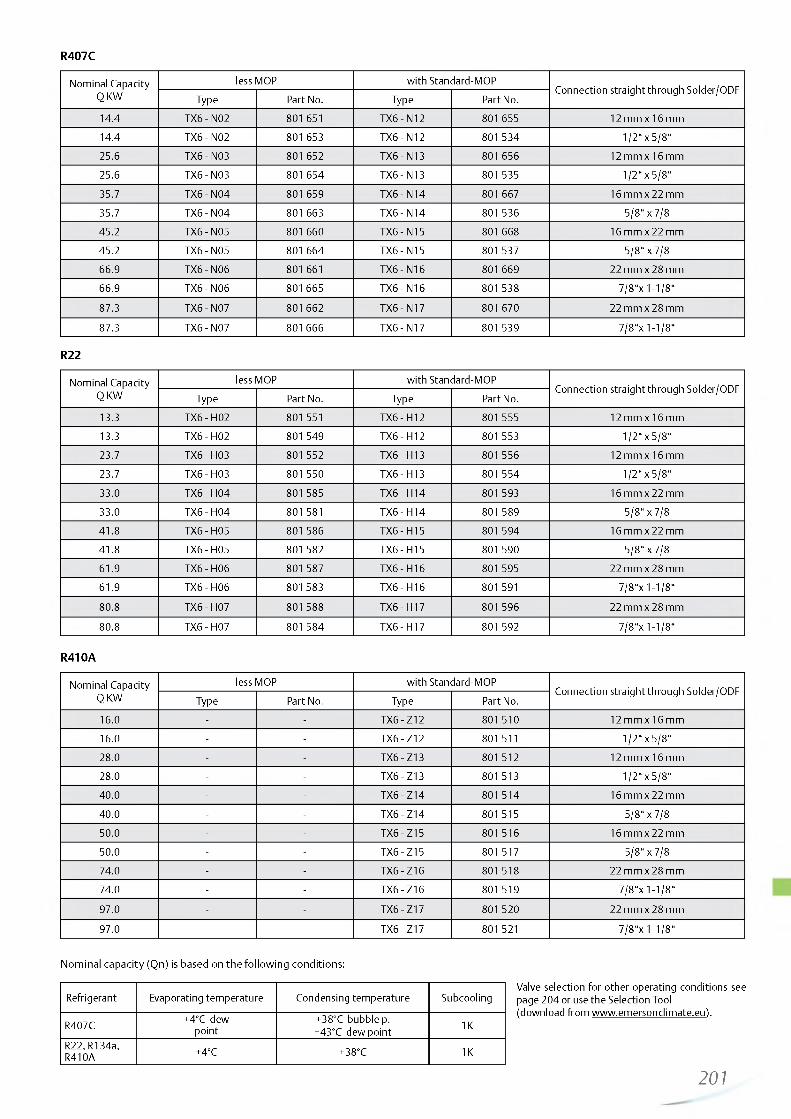
http://holodko.ru/
R407C
Nominal Capacity Q KW
less MOP with Standard-MOPConnection straight through Solder/ODF
Type Part No. Type Part No.14.4 TX6 - N02 801 651 TX6 - N12 801 655 12 mm x 16 mm14.4 TX6 - N02 801 653 TX6 - N12 801 534 1/2“ x 5/8“25.6 TX6 - N03 801 652 TX6 - N13 801 656 12 mm x 16 mm25.6 TX6- N03 801 654 TX6 - N13 801 535 1/2“ x 5/8“
35.7 TX6- N04 801 659 TX6 - N14 801 667 16 mm x 22 mm35.7 TX6- N04 801 663 TX6 - N14 801 536 5/8“ x 7/845.2 TX6- N05 801 660 TX6 - N15 801 668 16 mm x 22 mm45.2 TX6- N05 801 664 TX6 - N15 801 537 5/8“ x 7/866.9 TX6- N06 801 661 TX6 - N16 801 669 22 mm x 28 mm66.9 TX6- N06 801 665 TX6 - N16 801538 7/8“x 1-1/8“
87.3 TX6- N07 801 662 TX6 - N17 801 670 22 mm x 28 mm
87.3 TX6- N07 801 666 TX6 - N17 801 539 7/8“x 1-1/8“
R22
Nominal Capacity Q KW
less MOP with Standard-MOPConnection straight through Solder/ODF
Type Part No. Type Part No.13.3 TX6 - H02 801 551 TX6 - H12 801 555 12 mm x 16 mm13.3 TX6 - H02 801 549 TX6 - H12 801 553 1/2“ x 5/8“23.7 TX6- H03 801 552 TX6 - H13 801 556 12 mm x 16 mm23.7 TX6- H03 801 550 TX6 - H13 801 554 1/2“ x 5/8“
33.0 TX6- H04 801 585 TX6 - H14 801 593 16 mm x 22 mm33.0 TX6- H04 801 581 TX6 - H14 801 589 5/8“ x 7/841.8 TX6- H05 801 586 TX6 - H15 801 594 16 mm x 22 mm41.8 TX6- H05 801 582 TX6 - H15 801 590 5/8“ x 7/861.9 TX6- H06 801 587 TX6 - H16 801 595 22 mm x 28 mm61.9 TX6- H06 801 583 TX6 - H16 801 591 7/8“x 1-1/8“
80.8 TX6- H07 801 588 TX6 - H17 801 596 22 mm x 28 mm
80.8 TX6- H07 801 584 TX6 - H17 801 592 7/8“x 1-1/8“
R410A
Nominal Capacity Q KW
less MOP with Standard-MOPConnection straight through Solder/ODF
Type Part No. Type Part No.16.0 - - TX6 - Z12 801 510 12 mm x 16 mm16.0 - - TX6 - Z12 801 511 1/2“ x 5/8“28.0 - - TX6 - Z13 801 512 12 mm x 16 mm28.0 - - TX6 - Z13 801 513 1/2“ x 5/8“40.0 - - TX6 - Z14 801 514 16 mm x 22 mm
40.0 - - TX6 - Z14 801 515 5/8“ x 7/850.0 - - TX6 - Z15 801 516 16 mm x 22 mm50.0 - - TX6 - Z15 801 517 5/8“ x 7/874.0 - - TX6 - Z16 801 518 22 mm x 28 mm74.0 - - TX6 - Z16 801 519 7/8“x 1-1/8“
97.0 - - TX6 - Z17 801 520 22 mm x 28 mm
97.0 - - TX6 - Z17 801 521 7/8“x 1-1/8“
Valve selection for other operating conditions see page 204 or use the Selection Tool (download from www.emersonclimate.eu).
Nominal capacity (Qn) is based on the following conditions:
Refrigerant Evaporating temperature Condensing temperature Subcooling
R407C +4°C dew point
+38°C bubble p. +43°C dew point 1K
R22, R134a, R410A +4°C +38°C 1K
201

http://holodko.ru/
Thermo™-Expansion Valve Series TExchangeable Power Assemblies and Orifices
Features• Modular design for economical logistics and easy assembly
and servicing• Very good stability is attained because of the large forces
generated by the large diaphragm diameter• High quality materials and processes for high reliability and
long lifetime• Superior partial load performance due to double seat orifice
design (TJRE, TERE, TIRE & THRE)• Biflow capability for applications in heat pumps• Capillary tube length 1.5 m (TCLE, TJRE) and 3m (TERE, TIRE
& THRE)• PS: 31 bar. TS: -45 ... +65°C• No CE marking according art. 3.3 PED 97/23 EC
TCLE
A
Selection Chart for Orifices
Type Code
Valve Series External EqualizerC apacity Code -----------Refrigerant Code-----------Charge CodeMOP Code -----------Flange Sty le -----------
WL= Angle Style DL = Stra ight through
Connection
TCL E 100 H W 100 WL 10x16i i A A
R134a R22 R404A/R507 R407C
SeriesType
NominalCapacity
kWType
NominalCapacity
kWType Nominal Ca
pacity kW Type Nominal Capacity kW Orifice
TCLE
25 MW 1.5 50HW 1.9 25 SW 1.3 50 NW 2.1 X 22440-B1B75 MW 2.9 100 HW 3.7 75 SW 2.6 100 NW 4.0 X 22440-B2B150 MW 6.1 200 HW 7.9 150 SW 5.6 200 NW 8.5 X 22440-B3B
200 MW 9.3 250 HW 11.9 200 SW 8.4 300 NW 12.9 X 22440-B3.5B250 MW 13.5 300 HW 17.3 250 SW 12.2 400 NW 18.7 X 22440-B4B350 MW 17.3 500 HW 22.2 400 SW 15.7 550 NW 24.0 X 22440-B5B550 MW 23.6 750 HW 30.4 600 SW 21.5 750 NW 32.9 X 22440-B6B750 MW 32.0 1000 HW 41.1 850 SW 29.0 1000 NW 44.4 X 22440-B7B900 MW 37.2 1200 HW 47.8 1000 SW 33.8 1150 NW 51.7 X 22440-B8B
TJRE11 MW 45 14 HW 58 12 SW 40 14 NW 62 X 11873-B4B13 MW 57 18 HW 74 14 SW 51 17 NW 80 X 11873-B5B
TERE
16 MW 71 22 HW 91 18 SW 63 21 NW 99 X 9117-B6B19 MW 81 26 HW 104 20 SW 72 25 NW 112 X 9117-B7B25 MW 112 35 HW 143 27 SW 99 33 NW 155 X 9117-B8B31 MW 135 45 HW 174 34 SW 120 42 NW 188 X 9117-B9B
TIRE 45 MW 174 55 HW 223 47 SW 154 52 NW 241 X 9166-B10B
THRE55 MW 197 75 HW 253 61 SW 174 71 NW 273 X 9144-B11B68 MW 236 100 HW 302 77 SW 209 94 NW 327 X 9144-B13B
MOP Evaporating Temperature Range °C
Code bar R134aMW
2W
RH
R404ASW
R407CNW
R507SW
35 2.4 -45 .. 0 -45 .. -1540 2.8 -45 .. -18 -45 .. -18
55 3.8 -45 .. 11 05-4 05-4
65 4.5 -45 .. 075 5.2 -45 .. -2 -45 .. -280 5.5 -45 .. 0 -45 .. 0100 6.9 -45 .. 14
202
Nominal capacity (Qn) is based on the following conditions:
Refrigerant Evaporatingtemperature
Condensingtemperature Subcooling
R407C +4°C dew point
+38°Cbubble point +43°C dew point
1K
R22, R134a, R410A +4°C +38°C 1K
Valve selection for other operating conditions see page 204 oruse the Selection Tool(download from www.emersonclimate.eu).
___ —

http://holodko.ru/
Available upon special request:• Power assembly with solder connection for external pressure
equalization• Non-standard MOPs• Non-standard charges• Non-standard connection sizes. See page 217
Type Code
Power Assem b ly Refrigerant Code Charge Code MOP Code Capillary Tube Length- 1=1.5m; 2=3m External Equalization-
XB 1019 H W 1 00 - 1 B
Selection Chart for Power Assemblies and Recommended Flanges
Orifice
Connection Standard-Flange. Angle (see page 217)
Solder/ODF Power Assembly
mm inchX 22440-B1BX 22440-B2B
C 501 - 5 mm 10 x 16
C 501 - 5 3/8x 5/8X 22440-B3B
X 22440-B3.5BX 22440-B4BX 22440-B5B C 501 - 7 mm C 501 - 7 XB1019...1BX 22440-B6B 12 x 16 1/2 x 5/8
X 22440-B7B A 576 mm A 576X 22440-B8B 16 x 22 (22 x 28 ODM) 5/8 x 7/8 (7/8 x 1 1/8 ODM)
X 11873-B4B 10331 10331X 11873-B5B 22 x 22 7/8 x 7/8 (1 1/8 x 1 1/8 ODM)
X 9117-B6B9153
7/8x 7/8 (1 1/8 x 1 1/8 ODM)
X 9117-B7B9153 mm
22 x 22X 9117-B8BX 9117-B9B XC726...2BX 9166-B10BX 9144-B11B 9149 9149X 9144-B13B 22 x 22 7/8 x 7/8 (1 1/8 x 1 1/8 ODM)
Spare Parts
Type Part No.Gasket Set for T Series Valves X 13455 -1 027579Service Tool for T Series X 99999 800005Steel screws for following flange types:C501, 9761, 6346, A576 Screw ST 32 803 5739148, 9149, 9152, 9153, 10331, 10332 Screw ST 48 803 574
203

http://holodko.ru/
Correction Tables for Thermo™-Expansion Valves Series TI, TX3, TX6, T and LValve selection for operating conditions other than nominal conditions:
Qn = Qo x Kt x Kap
Qn: Nominal valve capacity Kt : Correction factor for evaporating and liquid temperatureQo: Required cooling capacity KAp: Correction factor for pressure drop at valve
Liquid Temperature entering Valve
°C
R410A (TX3/6 only) Correction Factor kt Evaporating Temperature (°C)
+ 20 + 15 + 10 +5 0 -5 - 1 0 -15 -2 0 -25 -30 -35 -40 -45
+65 1.75 1.76 1.78 1.80 1.83 1.8 6 1.89 2.18 2.55 3.05 3.69 4.49 5.46 6.62
+60 1.49 1.50 1.51 1.53 1.54 1.57 1.59 1.83 2.14 2.55 3.08 3.73 4.52 5.45
+55 1.31 1.32 1.33 1.35 1.36 1.38 1.40 1.61 1.87 2.23 2.68 3.25 3.92 4.72
+ 50 1.19 1 .2 0 1 .2 0 1 .2 1 1.23 1.24 1.26 1.44 1.6 8 2.0 0 2.40 2.90 3.49 4.20
+45 1 .0 1 1.09 1 . 1 0 1 . 1 1 1 . 1 2 1.13 1.15 1.32 1.53 1.82 2.18 2.63 3.17 3.80
+40 0.94 1.0 1 1.0 2 1.03 1.04 1.05 1.06 1 .2 1 1.41 1.67 2.0 1 2.41 2.90 3.48
+35 0.88 0.94 0.95 0.96 0.97 0.98 0.99 1.13 1.31 1.55 1.8 6 2.24 2.69 3.21
+30 0.83 0.89 0.89 0.90 0.91 0.91 0.92 1.06 1 .2 2 1.45 1.74 2.09 2.50 2.99
+25 0.84 0.84 0.85 0.85 0.86 0.87 0.99 1.15 1.36 1.63 1.96 2.35 2.80
+ 20 0.79 0.80 0.80 0.81 0.81 0.82 0.94 1.09 1.29 1.54 1.84 2 .2 1 2.64
Correction Factor kAp
Ap (bar) 1 2 3 4 5 6 7 8 9 10 11 1 2 13 14 15 16
KAp 3.74 2.65 2.16 1.87 1.67 1.53 1.41 1.32 1.25 1.18 1.13 1.08 1.04 1.0 0 0.97 0.94
Ap (bar) 17 18 19 20 21 22 23 24 25 26 27 28 29 30 31 32
KAp 0.91 0.88 0.86 0.84 0.82 0.80 0.78 0.76 0.75 0.73 0.72 0.71 0.69 0.68 0.67 0.66
Liquid Temperature entering Valve
°C
R134a Correction Factor kt Evaporating Temperature (°C)
+30 +25 +20 + 15 + 10 +5 0 -5 -1 0 -15 -2 0 -25 -30
+60 1 .2 2 1.25 1.27 1.30 1.33 1.36 1.40 1.44 1.48 1.75 2.08 2.46 2.94
+55 1.14 1.16 1.18 1 .2 1 1.23 1.26 1.29 1.33 1.36 1.60 1.90 2.25 2.68
+50 1.07 1.08 1 . 1 0 1.13 1.15 1.17 1 .2 0 1.23 1.26 1.48 1.76 2.07 2.46
+45 1 .0 0 1 .0 2 1.04 1.06 1.08 1 . 1 0 1 . 1 2 1.15 1.17 1.38 1.63 1.92 2.28
+40 0.93 0.96 0.98 0.99 1 .0 1 1.03 1.05 1.08 1 . 1 0 1.29 1.52 1.79 2 .1 2
+35 0.90 0.91 0.92 0.94 0.96 0.97 0.99 1 .0 1 1.03 1 .2 1 1.43 1 .6 8 1.99
+30 0.85 0.86 0.88 0.89 0.91 0.92 0.94 0.96 0.98 1.14 1.35 1.58 1.87
+25 0.82 0.83 0.85 0.86 0.87 0.89 0.91 0.92 1.08 1.27 1.49 1.76
+20 0.80 0.81 0.82 0.83 0.85 0.89 0.88 1 .0 2 1 .2 1 1.41 1.67
+ 15 0.77 0.78 0.79 0.81 0.82 0.84 0.97 1.15 1.34 1.58
+ 10 0.75 0.76 0.77 0.78 0.80 0.93 1.09 1.28 1.51
+5 0.73 0.74 0.75 0.76 0.89 1.04 1 .2 2 1.44
0 0.71 0.72 0.73 0.85 1 .0 0 1.17 1.37
-5 0.69 0.70 0.82 0.96 1 . 1 2 1.31
- 1 0 0.68 0.79 0.92 1.07 1.26
Correctio Factor kAp
Ap (bar) 0.5 1 .0 1.5 2.0 2.5 3.0 3.5 4.0 4.5 5.0 5.5 6.0 6.5 7.0 7.5 8.0
KAp 3.50 2.48 2.0 2 1.75 1.57 1.43 1.32 1.24 1.17 1 . 1 1 1.06 1.0 1 0.97 0.94 0.90 0.88
Ap (bar) 8.5 9.0 9.5 10 .0 10.5 1 1 .0 11.5 12 .0 12.5 13.0 13.5 14.0 14.5 15.0 15.5 16.0
KAp 0.85 0.83 0.80 0.78 0.76 0.75 0.73 0.72 0.69 0.66 0.64 0.62 0.60 0.58 0.57 0.55
In cases of subcooling of more than 15K please use additionally thecorrection factors on page 188 of this brochure.
204—
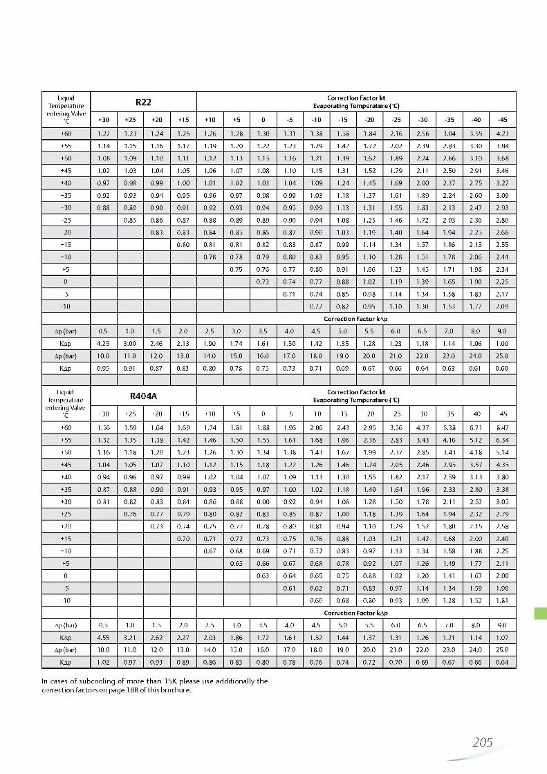
http://holodko.ru/
Liquid Temperature entering Valve
°C
R22 Correction Factor kt Evaporating Temperature (°C)
+30 +25 + 20 +15 + 10 +5 0 -5 - 1 0 -15 -2 0 -25 -30 -35 -40 -45
+60 1 .2 2 1.23 1.24 1.25 1.26 1.28 1.30 1.31 1.38 1.58 1.84 2.16 2.56 3.04 3.55 4.23
+ 55 1.14 1.15 1.16 1.17 1.19 1 .2 0 1 .2 2 1.23 1.29 1.42 1.72 2.0 2 2.39 2.83 3.30 3.94
+50 1.08 1.09 1 . 1 0 1 . 1 1 1 . 1 2 1.13 1.15 1.16 1 .2 1 1.39 1.62 1.89 2.24 2.66 3.10 3.68
+45 1 .0 2 1.03 1.04 1.05 1.06 1.07 1.08 1 . 1 0 1.15 1.31 1.52 1.79 2 .1 1 2.50 2.91 3.46
+40 0.97 0.98 0.99 1 .0 0 1.0 1 1.0 2 1.03 1.04 1.09 1.24 1.45 1.69 2.0 0 2.37 2.75 3.27
+35 0.92 0.93 0.94 0.95 0.96 0.97 0.98 0.99 1.03 1.18 1.37 1.61 1.89 2.24 2.60 3.09
+30 0.88 0.89 0.90 0.91 0.92 0.93 0.94 0.95 0.99 1.13 1.31 1.55 1.83 2.13 2.47 2.93
+25 0.85 0.86 0.87 0.88 0.89 0.89 0.90 0.94 1.08 1.25 1.46 1.72 2.03 2.36 2.80
+20 0.83 0.83 0.84 0.85 0.86 0.87 0.90 1.03 1.19 1.40 1.64 1.94 2.25 2.66
+ 15 0.80 0.81 0.81 0.82 0.83 0.87 0.99 1.14 1.34 1.57 1.8 6 2.15 2.55
+ 10 0.78 0.78 0.79 0.80 0.83 0.95 1 . 1 0 1.28 1.51 1.78 2.06 2.44
+5 0.75 0.76 0.77 0.80 0.91 1.06 1.23 1.45 1.71 1.98 2.34
0 0.73 0.74 0.77 0.88 1.0 2 1.19 1.39 1.65 1.90 2.25
-5 0.71 0.74 0.85 0.98 1.14 1.34 1.58 1.83 2.17
- 1 0 0.72 0.82 0.95 1 . 1 0 1.30 1.53 1.77 2.09
Correction Factor kAp
Ap (bar) 0.5 1.0 1.5 2.0 2.5 3.0 3.5 4.0 4.5 5.0 5.5 6.0 6.5 7.0 8.0 9.0
KAp 4.25 3.00 2.46 2.13 1.90 1.74 1.61 1.50 1.42 1.35 1.28 1.23 1.18 1.14 1.06 1.0 0
Ap (bar) 10 .0 1 1 .0 12 .0 13.0 14.0 15.0 16.0 17.0 18.0 19.0 20.0 2 1 .0 22 .0 23.0 24.0 25.0
KAp 0.95 0.91 0.87 0.83 0.80 0.78 0.75 0.73 0.71 0.69 0.67 0.66 0.64 0.63 0.61 0.60
Liquid Temperature
entering Valve °C
R404A Correction Factor kt Evaporating Temperature (°C)
+30 + 25 +20 + 15 + 10 + 5 0 -5 -1 0 -15 -2 0 -25 -30 -35 -40 -45
+60 1.56 1.59 1.64 1.69 1.74 1.81 1 .8 8 1.96 2.06 2.43 2.95 3.56 4.37 5.38 6.71 8.47
+ 55 1.32 1.35 1.38 1.42 1.46 1.50 1.55 1.61 1.6 8 1.96 2.36 2.83 3.43 4.16 5.12 6.34
+50 1.16 1.18 1 .2 0 1.23 1.26 1.30 1.34 1.38 1.43 1.67 1.99 2.37 2.85 3.43 4.18 5.14
+45 1.04 1.05 1.07 1 . 1 0 1 . 1 2 1.15 1.18 1 .2 2 1.26 1.46 1.74 2.05 2.46 2.95 3.57 4.35
+40 0.94 0.96 0.97 0.99 1 .0 2 1.04 1.07 1.09 1.13 1.30 1.55 1.82 2.17 2.59 3.13 3.80
+35 0.87 0.88 0.90 0.91 0.93 0.95 0.97 1.0 0 1 .0 2 1.18 1.40 1.64 1.96 2.33 2.80 3.38
+30 0.81 0.82 0.83 0.84 0.86 0.88 0.90 0.92 0.94 1.08 1.28 1.50 1.78 2 .1 1 2.53 3.05
+25 0.76 0.77 0.79 0.80 0.82 0.83 0.85 0.87 1.0 0 1.18 1.39 1.64 1.94 2.32 2.79
+20 0.73 0.74 0.75 0.77 0.78 0.80 0.81 0.94 1 . 1 0 1.29 1.52 1.80 2.15 2.58
+ 15 0.70 0.71 0.72 0.73 0.75 0.76 0.88 1.03 1 .2 1 1.42 1.6 8 2.00 2.40
+ 10 0.67 0.68 0.69 0.71 0.72 0.83 0.97 1.13 1.34 1.58 1 .8 8 2.25
+ 5 0.65 0.66 0.67 0.68 0.78 0.92 1.07 1.26 1.49 1.77 2 .1 1
0 0.63 0.64 0.65 0.75 0.88 1.0 2 1 .2 0 1.41 1.67 2.00
-5 0.61 0.62 0.71 0.83 0.97 1.14 1.34 1.59 1.90
- 1 0 0.60 0.68 0.80 0.93 1.09 1.28 1.52 1.81
Correction Factor kAp
Ap (bar) 0.5 1 .0 1.5 2.0 2.5 3.0 3.5 4.0 4.5 5.0 5.5 6.0 6.5 7.0 8.0 9.0
KAp 4.55 3.21 2.62 2.27 2.03 1 .8 6 1.72 1.61 1.52 1.44 1.37 1.31 1.26 1 .2 1 1.14 1.07
Ap (bar) 10 .0 1 1 .0 12 .0 13.0 14.0 15.0 16.0 17.0 18.0 19.0 20.0 2 1 .0 22 .0 23.0 24.0 25.0
KAp 1 .0 2 0.97 0.93 0.89 0.86 0.83 0.80 0.78 0.76 0.74 0.72 0.70 0.69 0.67 0.66 0.64
In cases of subcooling of more than 15K please use additionally thecorrection factors on page 188 of this brochure.
205

http://holodko.ru/
Liquid Temperature entering Valve
°C
R407C Correction Factor kt Evaporating Temperature (°C)
+30 +25 + 20 +15 + 1 0 +5 0 -5 - 1 0 -15 -2 0 -25
+55 1 .2 0 1 .2 1 1.23 1.26 1.28 1.31 1.34 1.37 1.40 1.63 1.98 2.42
+50 1 . 1 0 1 . 1 1 1.13 1.15 1.17 1.19 1 .2 2 1.24 1.27 1.48 1.79 2.18
+45 1 .0 2 1.03 1.05 1.06 1.08 1 . 1 0 1 . 1 2 1.14 1.17 1.35 1.64 2.00
+40 0.95 0.96 0.98 0.99 1.0 1 1 .0 2 1.04 1.06 1.08 1.25 1.52 1.84
+35 0.89 0.90 0.92 0.93 0.94 0.96 0.98 0.99 1.0 1 1.17 1.41 1.71
+30 0.85 0.85 0.87 0.88 0.89 0.90 0.92 0.93 0.95 1 . 1 0 1.32 1.60
+ 25 0.81 0.82 0.83 0.84 0.85 0.87 0.88 0.90 1.03 1.25 1.51
+ 20 0.78 0.79 0.80 0.81 0.82 0.84 0.85 0.98 1.18 1.43
+ 15 0.75 0.76 0.77 0.78 0.80 0.81 0.93 1 . 1 2 1.35
+ 10 0.73 0.74 0.75 0.76 0.77 0.89 1.07 1.29
+5 0.71 0.72 0.73 0.74 0.85 1 .0 2 1.23
0 0.69 0.70 0.71 81.00 0.98 1.18
-5 0.67 0.68 0.78 0.94 1.13
-1 0 0.65 0.75 0.90 1.08
Correction Factor kAp
Ap (bar) 0.5 1.0 1.5 2.0 2.5 3.0 3.5 4.0 4.5 5.0 5.5 6.0 6.5 7.0 8.0 9.0
KAp 4.78 3.33 2.72 2.36 2 .1 1 1.92 1.78 1.67 1.57 1.49 1.42 1.36 1.31 1.26 1.18 1 . 1 1
Ap (bar) 10 .0 1 1 .0 1 2 .0 13.0 14.0 15.0 16.0 17.0 18.0 19.0 20 .0 2 1 .0 22 .0 23.0 24.0 25.0
KAp 1.05 1 .0 1 0.96 0.92 0.89 0.86 0.83 0.81 0.79 0.76 0.75 0.73 0.71 0.70 0.68 0.67
Liquid Temperature entering Valve
°C
R507 Correction Factor kt Evaporating Temperature (°C)
+30 +25 + 20 +15 + 10 +5 0 -5 -1 0 -15 -2 0 -25 -30 -35 -40 -45
+60 1.54 1.57 1.61 1.65 1.71 1.76 1.83 1.90 1.98 2.36 2.84 3.44 4.23 5.25 6.61 8.45
+55 1.30 1.33 1.36 1.39 1.43 1.47 1.52 1.57 1.62 1.92 2.29 2.75 3.35 4.11 5.11 6.44
+50 1.15 1.17 1.19 1 .2 2 1.24 1.28 1.31 1.35 1.40 1.64 1.95 2.33 2.81 3.43 4.23 5.29
+45 1.03 1.05 1.07 1.09 1 . 1 1 1.14 1.17 1 .2 0 1.23 1.45 1.71 2.04 2.45 2.97 3.64 4.53
+40 0.94 0.96 0.97 0.99 1.0 1 1.03 1.06 1.08 1 . 1 1 1.30 1.53 1.82 2.18 2.63 3.22 3.98
+35 0.87 0.88 0.90 0.91 0.93 0.95 0.97 0.99 1.0 1 1.18 1.39 1.65 1.97 2.37 2.89 3.56
+30 0.81 0.82 0.83 0.85 0.86 0.88 0.89 0.91 0.93 1.09 1.28 1.51 1.80 2.17 2.63 3.23
+25 0.77 0.78 0.79 0.80 0.82 0.83 0.85 0.87 1.0 1 1.18 1.40 1.6 6 1.99 2.42 2.97
+20 0.73 0.74 0.75 0.77 0.78 0.79 0.81 0.94 1 . 1 0 1.30 1.54 1.85 2.24 2.74
+ 15 0.70 0.71 0.72 0.73 0.75 0.76 0.88 1.03 1 .2 1 1.44 1.73 2.09 2.55
+ 10 0.67 0.68 0.69 0.70 0.72 0.83 0.97 1.14 1.35 1.62 1.95 2.38
+5 0.64 0.65 0.67 0.68 0.78 0.92 1.07 1.27 1.52 1.83 2.23
0 0.62 0.63 0.64 0.74 0.87 1.0 2 1.2 0 1.43 1.73 2 .1 0
-5 0.60 0.61 0.70 0.82 0.96 1.14 1.35 1.63 1.98
- 1 0 0.58 0.67 0.78 0.91 1.08 1.28 1.54 1.87
Correction Factor kAp
Ap (bar) 0.5 1 .0 1.5 2.0 2.5 3.0 3.5 4.0 4.5 5.0 5.5 6.0 6.5 7.0 8.0 9.0
KAp 4.63 3.27 2.67 2.31 2.07 1.89 1.75 1.64 1.54 1.46 1.40 1.34 1.28 1.24 1.16 1.09
Ap (bar) 10 .0 1 1 .0 1 2 .0 13.0 14.0 15.0 16.0 17.0 18.0 19.0 20.0 2 1 .0 22 .0 23.0 24.0 25.0
KAp 1.03 0.99 0.94 0.91 0.87 0.85 0.82 0.79 0.77 0.75 0.73 0.71 0.70 0.68 0.67 0.65
In cases of subcooling of more than 15K please use additionally thecorrection factors on page 188 of this brochure.
206

http://holodko.ru/
The Following Correction Factors (kt) Related To Evaporating And Condensing Temperatures Apply
R407FCorrection factors for Thermo-Expansion valves
Evaporating temperature °C20 15 10 5 0 -5 -10 -15 -20 -25 -30 -35 -40 -45
Liquid
te
mpe
ratu
re °
C
65 1.51 1.53 1.55 1.58 1.61 1.64 1.68 1.90 2.24 2.68 3.22 3.86 4.63 5.52
60 1.35 1.37 1.39 1.41 1.43 1.46 1.49 1.68 1.98 2.36 2.83 3.39 4.04 4.8155 1.23 1.25 1.26 1.28 1.30 1.32 1.35 1.52 1.79 2.13 2.54 3.04 3.62 4.3050 1.14 1.15 1.16 1.18 1.20 1.22 1.24 1.39 1.64 1.95 2.32 2.77 3.29 3.9045 1.06 1.07 1.08 1.10 1.11 1.13 1.14 1.29 1.51 1.79 2.14 2.55 3.02 3.5740 0.99 1.00 1.01 1.02 1.04 1.05 1.07 1.20 1.41 1.67 1.98 2.36 2.80 3.3135 0.93 0.94 0.95 0.96 0.97 0.99 1.00 1.12 1.32 1.56 1.85 2.20 2.61 3.0830 0.88 0.89 0.90 0.91 0.92 0.93 0.94 1.06 1.24 1.47 1.74 2.07 2.44 2.8825 0.83 0.84 0.85 0.86 0.87 0.88 0.89 1.00 1.17 1.38 1.64 1.95 2.30 2.71
20 0.79 0.80 0.81 0.82 0.82 0.83 0.84 0.95 1.11 1.31 1.55 1.84 2.17 2.5615 0.76 0.76 0.77 0.78 0.78 0.79 0.80 0.90 1.05 1.24 1.47 1.74 2.06 2.4210 0.72 0.73 0.74 0.74 0.75 0.76 0.77 0.86 1.00 1.18 1.40 1.66 1.96 2.305 0.69 0.70 0.70 0.71 0.72 0.72 0.73 0.82 0.96 1.13 1.34 1.58 1.87 2.190 0.66 0.67 0.68 0.68 0.69 0.69 0.70 0.79 0.92 1.08 1.28 1.51 1.78 2.09-5 0.64 0.64 0.65 0.65 0.66 0.67 0.67 0.75 0.88 1.04 1.23 1.45 1.71 2.00
-10 0.62 0.62 0.62 0.63 0.63 0.64 0.65 0.72 0.84 1.00 1.18 1.39 1.64 1.92
For Applications As Expansion Valve The Following Correction Factors (kAp) Related To The Pressure Drop At Valve Apply
Correction factors for Thermo-Expansion valvesAP (bar) 1 1.5 2 2.5 3 3.5 4 4.5 5 5.5 6 6.5 7 7.5
kAP 3.51 2.87 2.48 2.22 2.03 1.88 1.76 1.66 1.57 1.5 1.43 1.38 1.33 1.28
AP (bar) 8 9 10 11 12 13 14 15 16 17 18 19 20 21
kAP 1.24 1.17 1.11 1.06 1.01 0.97 0.94 0.91 0.88 0.85 0.83 0.81 0.79 0.77
Superheat Adjustment Guidelines When TI Valves TI/TIE/TIS/TISE/TILE-NW, Designed For R407C Are Used In Applications With R407F
Standard charge (refrigerant)
Alternativerefrigerant
Evaporating temperature °C-40 -30 -20 -10 0
Number of turnsNW (R407C) R407F - 3/4 -1 -1 1/2 -2 1/4 -3
Minus means counter clockwise
207

http://holodko.ru/
Thermo™-Expansion Valve Series ZZfor Low Evaporating Temperatures between -45 and -120°C
Features• Modular design for economical logistics and easy assembly
and servicing• Very good stability is attained because of the large forces
generated by the large diaphragm diameter• High quality materials and processes for high reliability and
long lifetime• Capillary tube length 3 m• PS: 31 bar. TS: -120 ... +65°C• No CE marking according art. 3.3 PED 97/23 EC ZZCE
Type Code ZZC E 1 1/2 H W 35 WL 10x16
J A ▲ A A A A A
External Equalizer------Capacity Code ------Refrigerant Code ------Charge CodeMOP Code ------Flange Style ------
WL=Angle Style DL=Straight through
Connection ------
XC 726 H W 35 - 2 B
Power Assembly Refrigerant Code Charge Code MOP CodeCapillary Tube Length External Equalization
Available upon special request:• Power assembly with solder connection for external
pressure equalization• Non-standard MOPs• Non-standard charges• Non-standard connection sizes (Selection see page 217)
R22 R23 R404A / R507 Connection Standard- Flange, Angle Solder/ODFSeries
TypeNominal
TypeNominal
TypeNominal Orifice Power As
semblyCapacitykW
CapacitykW
CapacitykW mm inch
3/4 HW 1.8 2 BG 1.9 2/4 SW 1 .2 X 10-B01
1 1/2 HW 3.8 6 BG 4.0 1 1/2 SW 2.6 X 10-B02 C501 - 5mm 10 X 16
C501- 5 3/8” X 5/8”
2 1/2 HW 6.4 8 BG 6.8 2 1/2 SW 4.4 X 10-B03
ZZCE4 HW 10 .2 12 BG 10 .8 3 1/2 SW 7.0 X 10-B04 C501 - 7mm C501- 7
XC726... 2B6 HW 15.4 17 BG 16.3 5 SW 10 .6 X 10-B05
12 X 16 1 /2 ” X 5/8”
8 HW 20.5 25 BG 21.7 8 SW 14.1 X 10-B06 A 576mm 16 X 22 (22 X 28 ODM)
A 576 5/8” X 7/8” (7/8” X 1
1/8” ODM)10 HW 25.6 31 BG 27.1 9 SW 17.6 X 10-B07
Attention: To withstand stress at extremely low temperatures, thermo expansion valves series ZZ feature bronze bolts.
Nominal capacity (Qn) is based on the following conditions:
Preffered MOPs
MOPCode
MOP Evaporating Temperature Range °C
bar Tmax R22 R23 R404A/R507
20 1.4 -66°C -100 ... -71
35 2.4 -11°C 50-7
40 2.8 -14°c -75 ... -18
55 3.8 -7°C 05-7
60 4.1 -48°C -100 ... -51
125 8.6 -32°C -100 ... -35
Refrigerant Evaporatingtemperature
Condensingtemperature Subcooling
R22, R23, R404A,R507 +4°C +38°C 1K
Valve selection at other operating conditions see page 209
208

http://holodko.ru/
Spare Parts
Type Part No.
Gasket Set for T Series Valves X 13455 -1 027579Service Tool for T Series X 99999 800005Steel screws for following flange types:C501, 9761, 6346, A576 Screw ST 32 803 5759148, 9149, 9152, 9153, 10331, 10332 Screw ST 48 803 576
Correction Tables for Series ZZValve se lection fo r operating co nd itions o th er than specified on Q n: N om ina l va lve cap ac itypage 20 8 : Q o: Requ ired cooling cap ac ity
Qn = Qo x K x Kip Kf : C o rrec tio n fa c to r fo r evaporating and liquidtem p era tu re
Ki p: C o rrectio n fa c to r fo r pressure drop a t va lve
Liquid Temperature entering Valve
°C
R22 Correction Factor kt Evaporating Temperature (°C)
-45 -50 -55 -60 -65 -70
+ 10 1 .0 2 1 .2 1 1.42 1.6 6 1.97 2.30
0 0.94 1 . 1 2 1.30 1.53 1.75 2.0 2
-1 0 0.88 1.04 1 .2 1 1.42 1.61 1.83
-2 0 0.82 0.98 1.13 1.32 1.50 1.71
-30 0.77 0.92 1.05 1.23 1.39 1.56
-40 0.86 1.0 0 1.15 1.30 1.47
-50 1.09 1.25 1.42
Correction Factor kAp
Ap (bar) 0.5 1.0 1.5 2.0 2.5 3.0 3.5 4.0 4.5 5.0 6.0 7.0
KAp 4.40 3.10 2.50 2.20 2.00 1.80 1.70 1.60 1.50 1.40 1.30 1 .2 0
Ap (bar) 8.0 9.0 10 .0 1 1 .0 12 .0 13.0 14.0 15.0 16.0 17.0 18.0 19.0
KAp 1 . 1 0 1.04 0.98 0.94 0.90 0.87 0.83 0.81 0.78 0.76 0.74 0.72
Liquid Temperature entering Valve
°C
R23 Correction Factor kt Evaporating Temperature (°C)
-45 -50 -55 -60 -65 -70 -75 -80 -85 -90 -95 -1 0 0
-1 0 1.18 1.18 1.19 1 .2 1 1.28 1.48 1 .8 6 2 .2 1 2.73 3.36 4.15 5.06
-15 1 . 1 1 1 . 1 1 1 . 1 2 1.13 1 .2 0 1.39 1.74 2.07 2.56 3.14 3.88 4.72
-2 0 1.04 1.05 1.06 1.07 1.13 1.31 1.64 1.95 2.41 2.95 3.64 4.43
-25 0.99 0.99 1.0 0 1.0 1 1.07 1.24 1.55 1.84 2.27 2.78 3.43 4.17
-30 0.94 0.94 0.95 0.96 1 .0 2 1.17 1.47 1.75 2.15 2.63 3.24 3.94
-35 0.89 0.90 0.91 0.91 0.97 1 . 1 2 1.40 1.6 6 2.04 2.50 3.08 3.74
-40 0.85 0.86 0.86 0.87 0.92 1.06 1.33 1.58 1.94 2.38 2.92 3.55
-45 0.82 0.83 0.83 0.88 1.0 2 1.27 1.51 1.85 2.27 2.79 3.38
-50 0.79 0.80 0.84 0.97 1 .2 2 1.44 1.77 2.17 2.86 3.23
-55 0.76 0.81 0.93 1.17 1.38 1.70 2.07 2.55 3.09
-60 0.78 0.90 1 . 1 2 1.33 1.63 1.99 2.44 2.96
-65 0.86 1.08 1.27 1.57 1.91 2.35 2.84
-70 1.04 1.23 1.51 1.84 2.26 2.73
-75 1.18 1.45 1.77 2.18 2.63
-80 1.40 1.71 2 .10 2.54
Correction Factor kAp
Ap (bar) 0.5 1.0 1.5 2.0 2.5 3.0 3.5 4.0 4.5 5.0 6.0 7.0
KAp 4.20 2.97 2.43 2 .10 1.8 8 1.72 1.59 1.49 1.40 1.33 1 .2 1 1 . 1 2
Ap (bar) 8.0 9.0 10 .0 1 1 .0 12 .0 13.0 14.0 15.0 16.0 17.0 18.0 19.0
KAp 1.05 0.99 0.94 0.90 0.86 0.82 0.79 0.77 0.74 0.72 0.70 0.68
209

http://holodko.ru/
Liquid Temperature entering Valve
°C
R404A Correction Factor kt Evaporating Temperature (°C)
-40 -45 -50 -55 -60 -65 -70 -75
+40 1.40 1.76 2 .2 1 2.77 3.56 4.30 4.87 5.61
+35 1.24 1.55 1.94 2.42 3.09 3.71 4.17 4.77
+30 1 . 1 2 1.39 1.73 2.15 2.74 3.27 3.66 4.17
+25 1 .0 2 1.26 1.57 1.94 2.46 2.93 3.27 3.70
+20 0.94 1.16 1.44 1.77 2.24 2.66 2.96 3.34
+ 15 0.87 1.07 1.33 1.63 2.06 2.44 2.71 3.05
+ 10 0.81 1.0 0 1.23 1.52 1.91 2.26 2.49 2.80
+5 0.76 0.94 1.15 1.42 1.78 2 .1 0 2.32 2.60
0 0.71 0.88 1.08 1.33 1.67 1.97 2.17 2.43
-5 0.68 0.83 1 .0 2 1.25 1.57 1.85 2.04 2.28
-1 0 0.64 0.79 0.97 1.19 1.49 1.75 1.92 2.14
-15 0.61 0.75 0.92 1.13 1.41 1 .6 6 1.82 2.03
-2 0 0.58 0.72 0.88 1.07 1.34 1.57 1.73 1.92
-25 0.56 0.69 0.84 1.03 1.28 1.50 1.65 1.83
-30 0.54 0.66 0.80 0.98 1 .2 2 1.43 1.57 1.75
-35 0.51 0.63 0.77 0.94 1.17 1.36 1.49 1 .6 6
-40 0.60 0.74 0.90 1 . 1 2 1.31 1.43 1.59
-45 0.71 0.86 1.07 1.25 1.37 1.52
-50 0.83 1.03 1 .2 1 1.32 1.46
Correction Factor kAp
Ap (bar) 0.5 1 .0 1.5 2.0 2.5 3.0 3.5 4.0 4.5 5.0 6.0 7.0
KAp 4.73 3.34 2.73 2.36 2 .1 1 1.93 1.79 1.67 1.58 1.50 1.37 1.26
Ap (bar) 8.0 9.0 10 .0 1 1 .0 12 .0 13.0 14.0 15.0 16.0 17.0 18.0 19.0
KAp 1.18 1 . 1 1 1.06 1 .0 1 0.97 0.93 0.89 0.86 0.84 0.80 0.79 0.77
For the proper sizing of thermo expansion valves in cases of subcooling of more than 15K please use additionally the correction factors on page 188 of this brochure.
Liquid Temperature entering Valve
°C
R507 Correction Factor kt Evaporating Temperature (°C)
-45 -50 -55 -60 -65 -70
+30 1.26 1.67 2 .1 0 2.68 3.48 4.58
+ 20 1.07 1.41 1.77 2.25 2.89 3.78
+ 10 0.94 1 .2 2 1.52 1.92 2.46 3.23
0 0.83 1.08 1.33 1.6 8 2.16 2.82
- 1 0 0.75 0.95 1.19 1.49 1.92 2.48
-2 0 0.67 0.86 1.07 1.34 1.70 2 .20
-30 0.61 0.78 0.96 1 .2 1 1.54 2.00
-40 0.55 0.71 0.86 1.08 1.38 1.79
-50 0.79 0.99 1.24 1.62
Correction Factor kAp
Ap (bar) 0.5 1.0 1.5 2.0 2.5 3.0 3.5 4.0 4.5 5.0 6.0 7.0
KAp 4.77 3.37 2.75 2.38 2.13 1.95 1.80 1.69 1.59 1.51 1.38 1.27
Ap (bar) 8.0 9.0 10 .0 1 1 .0 1 2 .0 13.0 14.0 15.0 16.0 17.0 18.0 19.0
KAp 1.19 1 . 1 2 1.07 1 .0 2 0.97 0.94 0.90 0.87 0.84 0.82 0.79 0.77
For the proper sizing of thermo expansion valves in cases of subcoolingof more than 15K please use additionally the correction factors on page188 of this brochure.
210

http://holodko.ru/
Liquid Injection Valve Series LExchangeable Power Assemblies and Orifices
Features• Applications for Series L valves include superheat control (de
superheating of suction gas i.e., in hotgas bypass systems and interstage cooling in multiple stage compressors)
• Modular design for economical logistics and easy assembly and servicing
• Very good stability is attained because of the large forces generated by the large diaphragm diameter
• High quality materials and processes for high reliability and long lifetime
• Superior partial load performance due to seat orifice design (LJRE, LERE & LIRE)
• Capillary tube length 3 m• PS: 31 bar. TS: -45 ... +65°C• No CE marking according art. 3.3 PED 97/23 EC
Type Code XB1019 CL -_2 B
Power Assembly ___Charge Code __________Capillary Tube Length (3 m) External Equalization
Type Code
LCLE
LCL E 4 CL WL 10x16
Valve Series _____External EqualizerCapacity Code _____Charge Code Flange Style
WL=Angle Style DL=Straight through
Connection
SeriesNominal Capacity Qn
kW n OrificeConnections
Standard Flange. Angle Solder/ODF
PowerAssembly
R134a R22 R404A R407C R507 mm inch1 * 1.5 1.9 1.3 2.1 1.3 X 22440-B1B2 * 2.9 3.7 2.6 4.0 2.6 X 22440-B2B
3 * 6.1 7.9 5.6 8.5 5.6 X 22440-B3B C 501 - 5 mm 10 x16
3.5 * 9.3 11.9 8.4 12.9 8.4 X 22440-B3.5B
LCLE 4 * 13.5 17.3 12.2 18.7 12.2 X 22440-B4B6 * 17.3 22.2 15.7 24.0 15.7 X 22440-B5B C 501 - 7 mm7 * 23.6 30.4 21.5 32.9 21.5 X 22440-B6B 12 x 16 XB1019...2B9 * 32.0 41.1 29.0 44.4 29.0 X 22440-B7B A 576 mm A 576
10 * 37.2 47.8 33.8 51.7 33.8 X 22440-B8B16 x 22
(22 x 28 ODM)5/8x 7/8
(7/8 x 1 1/8 ODM)
11 * 45 58 40 62 40 X 11873-B4B
LJRE12 * 57 74 51 80 51 X 11873-B5B
10331 22 x 22
10331 7/8x 7/8
(1 1/8 x 1 1/8 ODM)
13 * 71 91 63 99 63 X 9117-B6B
LERE14 * 81 104 72 112 72 X 9117-B7B
9153 mm 22 x 22
915315 * 112 143 99 155 99 X 9117-B8B 7/8x 7/8 XC726...2B16 * 135 174 120 188 120 X 9117-B9B (1 1/8 x 1 1/8 ODM)
LIRE 17 * 174 223 154 241 154 X 9166-B10B
Superheat selection
* Charge Code
RefrigerantR134a R22 R404A R407C R507
CL - 15 K 22 K 13 K 22 K
GL 15 K 30 K 35 K 25 K 35 KUL 30 K 45 K 40 K
* Please indicate designation character for desired superheat
Nominal capacity (Qn) is based on the following conditions:
Refrigerant Evaporatingtemperature
Condensingtemperature
Subcooling
R407C +4°C dew point
+38°Cbubble point +43°C dew point
1K
R22, R134a, R404A, R507 +4°C +38°C 1K
Valve selection for other operating conditions see page 204
211

http://holodko.ru/
Available upon special request• Power assembly with solder connection for external
pressure equalization• Non-standard connection sizes see page 217
Spare Parts
Type Part No.
Gasket Set for L Series Valves X 13455 -1 027579Service Tool for L Series X 99999 800005Steel screws for following flange types:C501, 9761, 6346, A576 Screw ST 32 803 5739148, 9149, 9152, 9153, 10331, 10332 Screw ST 48 803 574
Correction Tables for Series L
Valve selection for desuperheating of suction gas:
The required desuperheating capacity Qdes has to be multiplied with the correction factors on page 204.
Qdes x Kt x KAp = Qn
Qdes: Required desuperheating capacityKt : Correction factor for evaporating and
liquid temperature KAp : Correction factor for pressure drop at valveQn : Nominal valve capacity
Condensing TemperatureBubble point
°CRefrigerant
Correction Factor kt Evaporating Temperature (°C)
+ 10 +5 0 -1 0 -2 0 -30 -40 -50
R22 0.33 0.36 0.40 0.47 0.56 0.66 0.78 0.93
+50 R407C 0.41 0.45 0.49 0.58 0.69(R407C: + 54 dew point) R134a 0.38 0.42 0.44 0.54 0.64
R507/R404A 0.50 0.54 0.59 0.70 0.83 0.98 1.18 1.38
R22 0.26 0.29 0.32 0.38 0.46 0.55 0.66 0.78
+40 R407C 0.32 0.35 0.39 0.46 0.55(R407C: + 45 dew point) R134a 0.31 0.33 0.36 0.44 0.52
R507/R404A 0.38 0.42 0.45 0.54 0.64 0.76 0.90 1.08
R22 0.20 0 .2 2 0.25 0.31 0.38 0.46 0.55 0.66
+30 R407C 0.25 0.28 0.31 0.37 0.45(R407C: + 35 dew point) R134a 0.24 0.26 0.29 0.35 0.43
R507/R404A 0.29 0.32 0.35 0.42 0.51 0.60 0.72 0.86
R22 0.15 0.17 0.19 0.25 0.31 0.38 0.46 0.56
+ 20 R407C 0.19 0 .2 1 0.24 0.30 0.37(R407C: + 26 dew point) R134a 0.18 0 .20 0 .2 2 0.28 0.35
R507/R404A 0 .2 2 0.25 0.27 0.33 0.40 0.48 0.58 0.70
Correction factors based on 20K superheat suction gas at the inlet of compressor, discharge temperature 28K above isentropic compression and 1K subcooling.
Valve selection for desuperheating of suction gas in conjunction with hotgas-bypass regulation:
The required bypass capacity QByp has to be multiplied with correction factor Kti per table below.
Qn x K = Q■̂Byp ti
QByp: Required bypass capacityKti : Correction factor for evaporatingtemperatureQn : Nominal valve capacity
212—

http://holodko.ru/
Liquid Injection Valves Series 935Exchangeable Power Assemblies and Orifices
Applications• Series 935 valves are applied as temperature controls.
Applications include:- Desuperheating of discharge gas on compressors. In this case bulbs are mounted on the high pressure outlet of the compressor- Control of compressor oil temperatures
• Series 935 valves shall not be used to control superheat
Features• Modular design for economical logistics and easy assembly
and servicing• Very good stability because of the large forces generated by
the large diaphragm diameter• High quality materials and processes for high reliability and
long lifetime• Combinations of different charges with various orifice springs
cover a very large application range• PS: 31 bar. TS: -45 ... +65°C• No CE marking according art. 3.3 PED 97/23 EC• Non-standard connection sizes see page 217
935
Type Code
Valve Series Temperature Code Capacity Code Flange Style
WL=Angle Style DL=Straight through
Connection Size
935 - 7 - B WL 10x16 ̂ A A A A
Type Code
Power Assembly Charge CodeCapillary Tube Length (3m)
XB1019 YL -2A ▲ ▲
SeriesNominal Capacity Qn
kW " Orifice Standard Flange. Angle Solder/ODF Power Assem
blyR134a R22 R404A R407C R507 mm inch
935- * -
A 4.0 5.2 3.8 5.6 3.8 X10-*01
C 501 - 5 mm 10 x 16
C 501 - 5 3/8x 5/8
B 7.8 10.1 7.4 10.9 7.4 X10-*02C 11.1 14.2 10.3 15.4 10.3 X10-*03D 16.3 21.1 15.6 22.8 15.6 X10-*04 C 501 - 7 mm
12 x 16C 501 - 7 1/2 x 5/8
i LE 22.5 28.9 21.0 31.2 21.0 X10-*05
i
XB1019 2 A
G 32.0 41.2 29.9 44.5 29.9 X10-*06 A 576 mm 16 x 22(22 x 28 ODM)
A 5765/8x 7/8(7/8 x 1-1/8 ODM)X 46.6 60.0 43.5 64.9 43.5 X10-*07
-** = Temperature Code Temperature Range °C
---------- 1----------* = Spring Code * = Charge Code
3 -1 / +17 B UL6 +14/+38 C KL
105 +44/+70 C YL106 +66/+94 C JL100 +94/+121 C LL
Nominal capacity (Qn) is based on the following conditions:
Refrigerant Evaporating temperature Condensing temperature Subcooling
R407C +4°C dew point
+38°C bubble point +43°C dew point 1K
R22, R134a, R404A,R507 +4°C +38°C 1K
Valve selection for other operating conditions see page 214.
213

http://holodko.ru/
Spare Parts
Description Type Part No.
Gasket Set for 935 Series Valves X 13455 -1 027579Service Tool for 935 Series X 99999 800005Steel screws for following flange types: C501, 9761, 6346, A576 Screw ST 32 803 573
Correction Tables for Series 935Valve selection for operating conditions other than nominal conditions:
Qn = Qo x Kt x K p
Qn: Nominal valve capacityQo: Required cooling or desuperheating capacityKt: Correction factor for evaporating and liquid temperatureKp: Correction factor for pressure drop at valve
Liquid Temperature entering Valve
°C
R134a Correction Factor kt Evaporating Temperature (°C)
+30 +25 + 20 + 15 + 10 +5 0 -5 - 1 0 -15 -2 0 -25 -30
+60 1 .2 2 1.25 1.27 1.30 1.33 1.36 1.40 1.44 1.48 1.51 1.56 1.61 1.67
+ 55 1.14 1.16 1.18 1 .2 1 1.23 1.26 1.29 1.33 1.36 1.39 1.43 1.47 1.52
+50 1.07 1.08 1 . 1 0 1.13 1.15 1.17 1 .2 0 1.23 1.26 1.28 1.32 1.36 1.39
+45 1.0 0 1 .0 2 1.04 1.06 1.08 1 . 1 0 1 . 1 2 1.15 1.17 1.19 1 .2 2 1.26 1.29
+40 0.93 0.96 0.98 0.99 1.0 1 1.03 1.05 1.08 1 . 1 0 1 . 1 2 1.14 1.17 1 .2 0
+35 0.90 0.91 0.92 0.94 0.96 0.97 0.99 1 .0 1 1.03 1.05 1.07 1 . 1 0 1 . 1 2
+30 0.85 0.86 0.88 0.89 0.91 0.92 0.94 0.96 0.98 0.99 1 .0 1 1.03 1.06
+25 0.82 0.83 0.85 0.86 0.87 0.89 0.91 0.92 0.94 0.95 0.97 1 .0 0
+20 0.80 0.81 0.82 0.83 0.85 0.89 0.88 0.89 0.91 0.92 0.94
+ 15 0.77 0.78 0.79 0.81 0.82 0.84 0.84 0.86 0.88 0.89
+ 10 0.75 0.76 0.77 0.78 0.80 0.81 0.82 0.84 0.85
+5 0.73 0.74 0.75 0.76 0.77 0.78 0.80 0.81
0 0.71 0.72 0.73 0.74 0.75 0.76 0.78
-5 0.69 0.70 0.71 0.72 0.73 0.74
-1 0 0.68 0.68 0.69 0.70 0.71
Correction Factor kAp
Ap (bar) 0.5 1 .0 1.5 2.0 2.5 3.0 3.5 4.0 4.5 5.0 5.5 6.0 6.5 7.0 7.5 8.0
KAp 3.50 2.48 2.0 2 1.75 1.57 1.43 1.32 1.24 1.17 1 . 1 1 1.06 1 .0 1 0.97 0.94 0.90 0.88
Ap (bar) 8.5 9.0 9.5 10 .0 10.5 1 1 .0 11.5 12 .0 13.0 14.0 15.0 16.0 17.0 18.0 19.0 20.0
KAp 0.85 0.83 0.80 0.78 0.76 0.75 0.73 0.72 0.69 0.66 0.64 0.62 0.60 0.58 0.57 0.55
214—

http://holodko.ru/
Liquid Temperature entering Valve
°C
R22 Correction Factor kt Evaporating Temperature (°C)
+30 +25 + 20 + 15 + 10 +5 0 -5 - 1 0 -15 -2 0 -25 -30 -35 -40 -45
+60 1 .2 2 1.23 1.24 1.25 1.27 1.28 1.30 1.32 1.34 1.36 1.38 1.41 1.44 1.47 1.50 1.53
+55 1.15 1.16 1.17 1.18 1.19 1 .2 0 1 .2 2 1.24 1.25 1.27 1.29 1.32 1.34 1.37 1.39 1.42
+ 50 1.08 1.09 1 . 1 0 1 . 1 1 1 . 1 2 1.14 1.15 1.16 1.18 1 .2 0 1 .2 2 1.24 1.26 1.28 1.30 1.33
+45 1.03 1.04 1.04 1.05 1.06 1.07 1.09 1 . 1 0 1 . 1 2 1.13 1.15 1.17 1.18 1 .2 0 1.23 1.25
+40 0.98 0.99 0.99 1.0 0 1.0 1 1 .0 2 1.03 1.04 1.06 1.07 1.09 1 . 1 0 1 . 1 2 1.14 1.16 1.18
+35 0.93 0.94 0.95 0.95 0.96 0.97 0.98 0.99 1.0 1 1.0 2 1.03 1.05 1.06 1.08 1 . 1 0 1 . 1 2
+30 0.89 0.90 0.90 0.91 0.92 0.93 0.94 0.95 0.96 0.97 0.98 1.0 0 1.0 1 1.03 1.04 1.06
+ 25 0.86 0.87 0.87 0.88 0.89 0.90 0.91 0.92 0.93 0.94 0.95 0.96 0.98 0.99 1 .0 1
+20 0.83 0.84 0.84 0.85 0.86 0.87 0.88 0.89 0.90 0.91 0.92 0.93 0.95 0.96
+ 15 0.80 0.81 0.82 0.82 0.83 0.84 0.85 0.86 0.87 0.88 0.89 0.91 0.92
+ 10 0.78 0.79 0.79 0.80 0.81 0.82 0.83 0.84 0.85 0.86 0.87 0.88
+5 0.76 0.76 0.77 0.78 0.79 0.79 0.80 0.81 0.82 0.83 0.85
0 0.74 0.74 0.75 0.76 0.77 0.77 0.78 0.79 0.80 0.81
-5 0.72 0.72 0.73 0.74 0.75 0.75 0.76 0.77 0.78
-1 0 0.70 0.71 0.71 0.72 0.73 0.71 0.74 0.75
Correction Factor kAp
Ap (bar) 0.5 1.0 1.5 2.0 2.5 3.0 3.5 4.0 4.5 5.0 5.5 6.0 6.5 7.0 8.0 9.0
KAp 4.25 3.00 2.46 2.13 1.90 1.74 1.61 1.50 1.42 1.35 1.28 1.23 1.18 1.14 1.06 1.0 0
Ap (bar) 10 .0 1 1 .0 1 2 .0 13.0 14.0 15.0 16.0 17.0 18.0 19.0 20.0 2 1 .0 22 .0 23.0 24.0 25.0
KAp 0.95 0.91 0.87 0.83 0.80 0.78 0.75 0.73 0.71 0.69 0.67 0.66 0.64 0.63 0.61 0.60
Liquid Temperature entering Valve
°C
R404A Correction Factor kt Evaporating Temperature (°C)
+30 +25 + 20 + 15 + 10 +5 0 -5 - 1 0 -15 -2 0 -25 -30 -35 -40 -45
+60 1.56 1.59 1.64 1.69 1.74 1.81 1.8 8 1.96 2.06 2.16 2.28 2.42 2.57 2.75 2.95 3.19
+55 1.32 1.35 1.38 1.42 1.46 1.50 1.55 1.61 1.6 8 1.75 1.83 1.92 2.0 1 2.13 2.25 2.39
+ 50 1.16 1.18 1 .2 0 1.23 1.26 1.30 1.34 1.38 1.43 1.48 1.54 1.61 1.6 8 1.75 1.84 1.94
+45 1.04 1.05 1.07 1 . 1 0 1 . 1 2 1.15 1.18 1 .2 2 1.26 1.30 1.34 1.39 1.45 1.51 1.57 1.64
+40 0.94 0.96 0.97 0.99 1 .0 2 1.04 1.07 1.09 1.13 1.16 1 .2 0 1.24 1.28 1.33 1.38 1.43
+35 0.87 0.88 0.90 0.91 0.93 0.95 0.97 1 .0 0 1.0 2 1.05 1.08 1 . 1 1 1.15 1.19 1.23 1.27
+30 0.81 0.82 0.83 0.84 0.86 0.88 0.90 0.92 0.94 0.96 0.99 1 .0 2 1.05 1.08 1 . 1 1 1.15
+ 25 0.76 0.77 0.79 0.80 0.82 0.83 0.85 0.87 0.89 0.92 0.94 0.97 0.99 1 .0 2 1.05
+20 0.73 0.74 0.75 0.77 0.78 0.80 0.81 0.83 0.85 0.87 0.90 0.92 0.95 0.97
+ 15 0.70 0.71 0.72 0.73 0.75 0.76 0.78 0.80 0.82 0.84 0.86 0.88 0.90
+ 10 0.67 0.68 0.69 0.71 0.72 0.74 0.75 0.77 0.79 0.81 0.83 0.85
+5 0.65 0.66 0.67 0.68 0.70 0.71 0.73 0.74 0.76 0.78 0.80
0 0.63 0.64 0.65 0.66 0.68 0.69 0.71 0.72 0.74 0.75
-5 0.61 0.62 0.63 0.65 0.66 0.67 0.69 0.70 0.72
-1 0 0.60 0.61 0.62 0.63 0.64 0.65 0.67 0.68
Correction Factor kAp
Ap (bar) 0.5 1.0 1.5 2.0 2.5 3.0 3.5 4.0 4.5 5.0 5.5 6.0 6.5 7.0 8.0 9.0
KAp 4.55 3.21 2.62 2.27 2.03 1 .8 6 1.72 1.61 1.52 1.44 1.37 1.31 1.26 1 .2 1 1.14 1.07
Ap (bar) 10 .0 1 1 .0 12 .0 13.0 14.0 15.0 16.0 17.0 18.0 19.0 20.0 2 1 .0 22 .0 23.0 24.0 25.0
KAp 1.0 2 0.97 0.93 0.89 0.86 0.83 0.80 0.78 0.76 0.74 0.72 0.70 0.69 0.67 0.66 0.64
215

http://holodko.ru/
Liquid Temperature entering Valve
°C
R407C Correction Factor kt Evaporating Temperature (°C)
+30 +25 + 20 + 15 + 10 +5 0 -5 - 1 0 -15 -2 0 -25
+ 55 1 .2 0 1 .2 1 1.23 1.26 1.28 1.31 1.34 1.37 1.40 1.44 1.48 1.52
+50 1 . 1 0 1 . 1 1 1.13 1.15 1.17 1.19 1 .2 2 1.24 1.27 1.30 1.33 1.37
+45 1 .0 2 1.03 1.05 1.06 1.08 1 . 1 0 1 . 1 2 1.14 1.17 1.19 1 .2 2 1.25
+40 0.95 0.96 0.98 0.99 1 .0 1 1.0 2 1.04 1.06 1.08 1 . 1 1 1.13 1.16
+35 0.89 0.90 0.92 0.93 0.94 0.96 0.98 0.99 1.0 1 1.03 1.05 1.07
+30 0.85 0.85 0.87 0.88 0.89 0.90 0.92 0.93 0.95 0.97 0.99 1.0 1
+25 0.81 0.82 0.83 0.84 0.85 0.87 0.88 0.90 0.91 0.93 0.95
+20 0.78 0.79 0.80 0.81 0.82 0.84 0.85 0.86 0.88 0.90
+ 15 0.75 0.76 0.77 0.78 0.80 0.81 0.82 0.84 0.85
+ 10 0.73 0.74 0.75 0.76 0.77 0.78 0.80 0.81
+ 5 0.71 0.72 0.73 0.74 0.75 0.76 0.77
0 0.69 0.70 0.71 0.72 0.73 0.74
-5 0.67 0.68 0.69 0.70 0.71
-1 0 0.65 0.66 0.67 0.68
Correction Factor kAp
Ap (bar) 0.5 1 .0 1.5 2.0 2.5 3.0 3.5 4.0 4.5 5.0 5.5 6.0 6.5 7.0 8.0 9.0
KAp 4.78 3.33 2.72 2.36 2 . 1 1 1.92 1.78 1.67 1.57 1.49 1.42 1.36 1.31 1.26 1.18 1 . 1 1
Ap (bar) 10 .0 1 1 .0 12 .0 13.0 14.0 15.0 16.0 17.0 18.0 19.0 20.0 2 1 .0 22 .0 23.0 24.0 25.0
KAp 1.05 1.0 1 0.96 0.92 0.89 0.86 0.83 0.81 0.79 0.76 0.75 0.73 0.71 0.70 0.68 0.67
Note: See page 188 for determining of conditions for systems with R407C.
Liquid Temperature entering Valve
°C
R507 Correction Factor kt Evaporating Temperature (°C)
+30 +25 + 20 + 15 + 10 +5 0 -5 - 1 0 -15 -2 0 -25 -30 -35 -40 -45
+60 1.54 1.57 1.61 1.65 1.71 1.76 1.83 1.90 1.98 2.08 2.18 2.30 2.43 2.58 2.75 2.95
+55 1.30 1.33 1.36 1.39 1.43 1.47 1.52 1.57 1.62 1.69 1.76 1.83 1.92 2.0 2 2 . 1 2 2.25
+50 1.15 1.17 1.19 1 .2 2 1.24 1.28 1.31 1.35 1.40 1.44 1.49 1.55 1.61 1 .6 8 1.76 1.84
+45 1.03 1.05 1.07 1.09 1 . 1 1 1.14 1.17 1 .2 0 1.23 1.27 1.31 1.36 1.40 1.46 1.52 1.58
+40 0.94 0.96 0.97 0.99 1.0 1 1.03 1.06 1.08 1 . 1 1 1.14 1.17 1 .2 1 1.25 1.29 1.34 1.39
+35 0.87 0.88 0.90 0.91 0.93 0.95 0.97 0.99 1 .0 1 1.04 1.07 1 . 1 0 1.13 1.16 1 .2 0 1.24
+30 0.81 0.82 0.83 0.85 0.86 0.88 0.89 0.91 0.93 0.96 0.98 1 .0 1 1.03 1.06 1.09 1.13
+25 0.77 0.78 0.79 0.80 0.82 0.83 0.85 0.87 0.89 0.91 0.93 0.95 0.98 1 .0 1 1.03
+20 0.73 0.74 0.75 0.77 0.78 0.79 0.81 0.83 0.85 0.87 0.89 0.91 0.93 0.96
+ 15 0.70 0.71 0.72 0.73 0.75 0.76 0.78 0.79 0.81 0.83 0.85 0.87 0.89
+ 10 0.67 0.68 0.69 0.70 0.72 0.73 0.74 0.76 0.78 0.79 0.81 0.83
+5 0.64 0.65 0.67 0.68 0.69 0.70 0.72 0.73 0.75 0.76 0.78
0 0.62 0.63 0.64 0.65 0.66 0.68 0.69 0.70 0.72 0.73
-5 0.60 0.61 0.62 0.63 0.64 0.65 0.66 0.68 0.69
-1 0 0.58 0.59 0.60 0.61 0.62 0.63 0.64 0.65
Correction Factor kAp
Ap (bar) 0.5 1 .0 1.5 2.0 2.5 3.0 3.5 4.0 4.5 5.0 5.5 6.0 6.5 7.0 8.0 9.0
KAp 4.63 3.27 2.67 2.31 2.07 1.89 1.75 1.64 1.54 1.46 1.40 1.34 1.28 1.24 1.16 1.09
Ap (bar) 10 .0 1 1 .0 12 .0 13.0 14.0 15.0 16.0 17.0 18.0 19.0 20.0 2 1 .0 22 .0 23.0 24.0 25.0
KAp 1.03 0.99 0.94 0.91 0.87 0.85 0.82 0.79 0.77 0.75 0.73 0.71 0.70 0.68 0.67 0.65
216

http://holodko.ru/
Angle Style Straight Through Connectionsfor Valve
SeriesType Part No. Type Part No.mm inch
Solder ODF Solder ODM Solder ODF Solder ODMC 501 - 5 803 232 9761 - 3 803 240 - - 3/8x 5/8 - TCLE
C 501 - 5 MM 803 233 9761 - 3 MM 803 241 10 x 16 - - - ZZCEC 501 - 7 803 234 9761 - 4 803350 - - 1/2 x 5/8 - LCLE
C 501 - 7 MM 803 235 9761 - 4 MM 803 243 12 x 16 - - - 935 A-X
- - 6346 - 17 803 330 16 x 22 - 5/8x 7/8 - CPHE 1
A 576 803 238 - - - - 5/8x 7/8 7/8x 1-1/8 CPHE 2A 576 - MM 803 239 - - 16 x 22 22 x 28 - -
10331 803 338 10332 803 324 22 x 22 - 7/8x 7/8 1-1/8 x 1-1/8TJRE LJRE
CPHE 3
9153 9153 MM
803 244 803 245
9152 9152 MM
803 286 803 287 22 x 22 28 x 28
7/8x 7/8 1-1/8 x 1-1/8
TERE TIRE LERE LIRE
CPHE 3.5 CPHE 4 CPHE 5
9149 803 284 9148 803 283 22 x 22 - 7/8x 7/8 1-1/8 x 1-1/8 THRE CPHE 6
217

http://holodko.ru/
218__—

http://holodko.ru/
Solenoid Valves

http://holodko.ru/
2-Way-Solenoid ValvesBasic Terms and Technical Information
Operating principles
Directly actuated: The magnetic field of the solenoid coil forces a movement of the plunger and thus causes the opening of the valve seat.
Servo actuated: The magnetic field of the solenoid coil is only utilized for the opening of the pilot valve seat. The necessary energy to actuate the piston or diaphragm of the main valve seat is provided by the refrigerant flow and results in a certain pressure drop.
Minimum Pressure DropDirectly actuated solenoid valves do not require a minimum pressure drop for proper operation.
Servo operated solenoid valves require a minimum pressure drop of approximately 0.05 bar to remain fully open. In case of insufficent refrigerant flow, this value will not be reached and the solenoid valve may close unintentionally. These closures may lead to malfunctions and oscillations in the refrigeration circuit. Improper sizing of solenoid valves (i.e., use of excessively large solenoid valves) is the main cause of this effect. This is particularly important in capacity controlled refrigeration circuits.
Therefore the decisive factor for proper solenoid valve sizing is the respective capacity of the valve and not its connection size.
Formula for calculating the actual pressure drop of a solenoid valve:Ap, = Ap2 x (Qn,/Qn2)2
Ap1: Actual pressure dropAp2: Nominal pressure drop at Qn1Qn1: Calculated nominal capacityQn2: Nominal capacity of selected valve
Maximum Operating Pressure Differential (MOPD)MOPD is the maximum pressure differential between inlet and outlet of the solenoid valve which permits proper opening of the valve. When used with Alco AC solenoid coils all Alco solenoid valves employ 25 bar MOPD.
Operation in conjunction with DC solenoid coils lead to reduced MOPD values depending on valve type and size. The DS2 Chopper Plugs allow the use of 24VAC coils with 24VDC by converting the DC in an AC voltage. Please contact Emerson Climate Technologies application engineering for additional details.
Selection Guide for Solenoid Valves
Selection Criteria
Series
110 RB 200 RB240 RA 540 RA
M368/9/12/16T9 16T11/20 8/9/12/16 20
2-Way + + + + + +
3-Way +
Normally Closed (NC) + + + +
Normally Open (NO) + +
Min. Pressure Differential (bar) 0.00 0.05 0.05 0.05 0.05 0.05MWP (bar) 31 31 31 31 31 28 35Media Temp. Range (°C) -40 / +120 -40 / +120 -40/+120 -40/+120 -40/+120 -40 / +120 -40 / +120Coil Type ASC ASC ASC ASC ASC ASC ASCCatalogue Page 222 222 222 222 223 223 227
Type Code 200 RB 6 T 4
Model Seat diameter T SolderSeries in multiples of F Flare
Tube connection in multiple of 7 S” . i.e. V2”or nearest mm equivalent'/ ” i e 3/ ”/16 * 18
220—
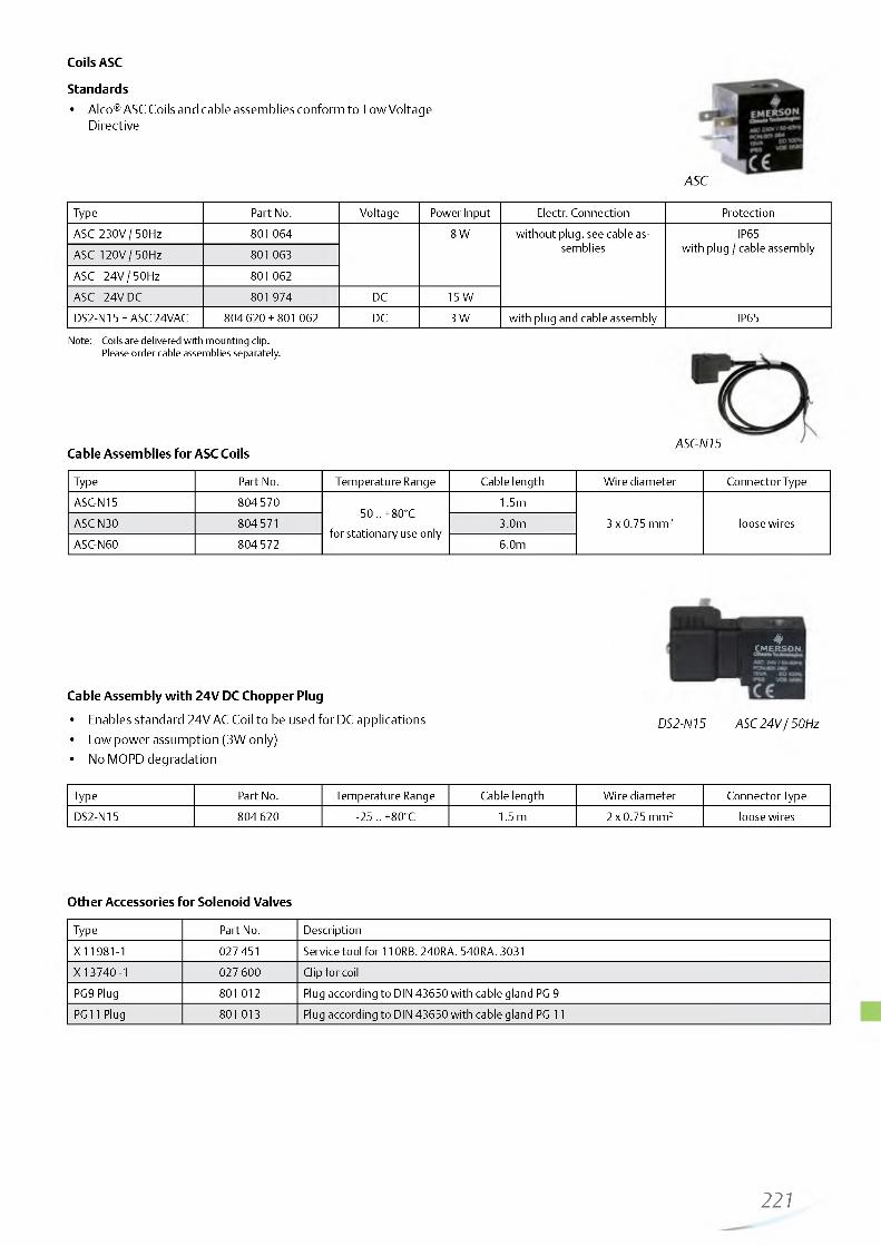
http://holodko.ru/
Coils ASC
Standards• Alco® ASC Coils and cable assemblies conform to Low Voltage
Directive
ASC
Type Part No. Voltage Power Input Electr. Connection ProtectionASC 230V / 50Hz 801 064 8 W without plug. see cable as
sembliesIP65
with plug / cable assemblyASC 120V / 50Hz 801 063
ASC 24V / 50Hz 801 062ASC 24V DC 801 974 DC 15 WDS2-N15 + ASC 24VAC 804 620 + 801 062 DC 3 W with plug and cable assembly IP65
Note: Coils are delivered with mounting clip.Please order cable assemblies separately.
Cable Assemblies for ASC CoilsASC-N15
Type Part No. Temperature Range Cable length Wire diameter Connector TypeASC-N15 804570
-50 .. +80°C for stationary use only
1.5m3 x 0.75 mm2 loose wiresASC-N30 804 571 3.0m
ASC-N60 804572 6.0m
♦EM ERSON
Cable Assembly with 24V DC Chopper Plug
• Enables standard 24V AC Coil to be used for DC applications• Low power assumption (3W only)• No MOPD degradation
DS2-N15 ASC 24V / 50Hz
Type Part No. Temperature Range Cable length Wire diameter Connector TypeDS2-N15 804 620 -25 .. +80°C 1.5 m 2 x 0.75 mm2 loose wires
Other Accessories for Solenoid Valves
Type Part No. Description
X 11981-1 027 451 Service tool for 110RB. 240RA. 540RA. 3031X 13740 -1 027600 Clip for coilPG9 Plug 801 012 Plug according to DIN 43650 with cable gland PG 9PG11 Plug 801 013 Plug according to DIN 43650 with cable gland PG 11
221

http://holodko.ru/
2-Way Solenoid Valves Series 110,Normally Closed
Features• Compact size• Snap-on clip for attaching solenoid coils• No disassembly necessary for soldering
Standards• 240 RA 16T11 and 20 are CE marked per PED
Capacity Data 240 RA
Type
Nominal Capcity Qn (kW)
kv-valuem3/h
Ap min bar
Liquid Hot Gas Suction Gas
R134a R22 R404AR507 R407C R407F R134a R22 R404A
R507 R407C R134a R22 R507 R407C
110RB2 3.5 3.8 2.5 3.6 4.2 1.6 2.0 1.7 2.1 0.2 0200 RB 3 6.6 7.1 4.6 6.8 7.9 3.0 3.7 3.2 3.9 0.4 0.05200 RB 4 15.5 16.8 10.9 16.1 18.8 7.1 8.8 7.5 9.2 0.9 0.05200 RB 6 27.3 29.5 18.9 28.0 33.0 12.5 15.4 13.1 16.1 1.6 0.05240 RA 8 36.3 39.3 25.2 37.3 43.9 16.7 20.5 17.4 21.4 4.2 5.6 4.6 5.2 2.3 0.05
240 RA 9 76.2 82.5 52.9 78.4 92.2 35.1 43.1 36.5 44.9 8.8 11.7 9.7 10.9 4.8 0.05240 RA 12 85.7 92.8 59.5 88.1 103.7 39.4 48.4 41.1 50.5 9.9 13.1 10.9 12.3 5.4 0.05240 RA 16 139.1 150.5 96.5 142.9 168.2 64.0 78.5 66.6 81.9 16.0 21.3 17.7 19.9 8.8 0.05240 RA 20 202.6 219.3 140.7 208.3 245.2 93.2 114.4 97.1 119.3 33.0 31.0 25.7 29.0 12.8 0.05
Nominal capacities at +38°C condensing temperature. +4°C evaporating temperature. 0.15 bar pressure drop between valve inlet and outlet in liquid applications (for hot gas applications 1 bar pressure drop and +18 °C suction gas temperature); subcooling 1 K. Correction tables for other operating conditions see page 227
Selection Guide
Type Part No.Connection Solder / ODF
mm Inch
110RB2T2 801 217 6T2 801 210 1/4T3 801 209 10 3/8
200 RB 3 T3 801 239 10 3/8
200 RB 4
T3 801 176 10T3 801 190 3/8T4 801 178 12T4 801179 1/2
200 RB 6T4 801 182 12T4 801 183 1/2T5 801 186 16 5/8
240 RA 8T5 801 160 5/8T7 801 143 22 7/8
240 RA 9
T5 801 161 16 5/8T7 801 162 22 7/8T9 801 142 1-1/8
240 RA 12T9 801 163 22 7/8T11 801 144 1-1/8
240 RA 16T9 801 164 1-1/8T11 801 166 35 1-3/8
240 RA 20
T11-M 801 172 35 1-3/8
T13-M 801 224 42T13-M 801 173 1-5/8T17-M 801 174 54 2-1/8
Special Versions:• Manual stems available upon request for
Series 240 RA 8 to 240 RA 16 (Type M).
Manual stems standard on Series 240 RA 20.
Options:• Actuation coils available for various
voltages. see page 221
222

http://holodko.ru/
2-Way Solenoid Valves Series 540Normally Open
Features• Compact size• Snap-on clip for attaching solenoid coils• No disassembly necessary for soldering
540 RA
Capacity Data
Type
Nominal Capcity Qn (kW)kv-
valuem3/h
Ap min bar
Liquid Hot Gas Suction Gas
R134a R22 R404AR507 R407C R134a R22 R404A
R507 R407C R134a R22 R507 R407C
540 RA 8 36.3 39.3 25.2 37.3 16.7 20.5 17.4 21.4 4.2 5.6 4.6 5.2 2.3 0.05540 RA 9 76.2 82.5 52.9 78.4 35.1 43.1 36.5 44.9 8.8 11.7 9.7 10.9 4.8 0.05540 RA 12 85.7 92.8 59.5 88.1 39.4 48.4 41.1 50.5 9.9 13.1 10.9 12.3 5.4 0.05540 RA 16 139.1 150.5 96.5 142.9 64.0 78.5 66.6 81.9 16.0 21.3 17.7 19.9 8.8 0.05
540 RA 20 202.6 219.3 140.7 208.3 93.2 114.4 97.1 119.3 23.3 31.0 25.7 29.0 12.8 0.05
Nominal capacities at +38°C condensing temperature. +4°C evaporating temperature. 0.15 bar pressure drop between valve inlet and outlet in liquid applications (for hot gas applications 1 bar pressure drop and +18 °C suction gas temperature); subcooling 1 K. Correction tables for other operating conditions see page 227.
Selection Guide
Type Part No.Connection Solder / ODF
mm Inch540 RA 8 T5 046 265 5/8
540 RA 9T5 046 266 5/8T7 046 268 22 7/8
540 RA 12 T7 046 269 22 7/8540 RA 16 T9 046270 1-1/8540 RA 20 T11 047 953 35 1-3/8
Options:• Actuation coils available for various
voltages, see page 221
Accessories and spare parts for solenoid valves
Description Type Part No.Service tool for 110 RB, 240 RA, 540 RA
X 11981 - 1 027 451
Gasket kits110RB KS 30040-2 801 232200RB KS 30039-1 801 233240RA8 KS 30061-1 801 234
240RA9/12 KS 30062-1 801 235240RA16 KS 30065-1 801 236240RA20 KS 30097-1 801 237
Description Type Part No.110RB KS 30040-1 801 206
200RB KS30039/ KS30109 801 205
240RA8 KS30061 801 262240RA9 KS 30062 801 263240RA12 KS 30063 801 264
240RA16 KS 30065 801 200240RA20 KS 30097 801 216
223
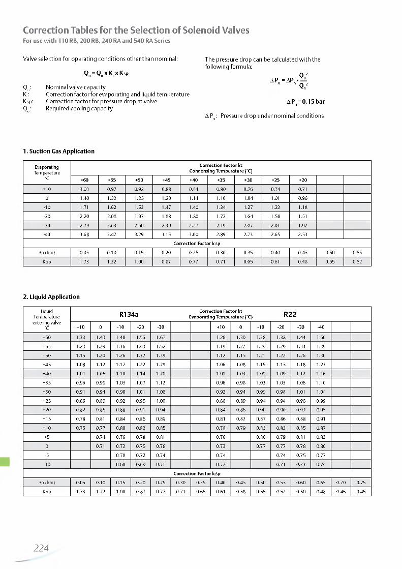
http://holodko.ru/
Correction Tables for the Selection of Solenoid ValvesFor use with 110 RB, 200 RB, 240 RA and 540 RA Series
Valve selection for operating conditions other than nominal: The pressure drop can be calculated with thefollowing formula:
Qn = Qo x Kt x Kap Q 2A P = AP * _ _
0 n j-w 2Qn: Nominal valve capacity QnKt: Correction factor for evaporating and liquid temperatureKap: Correction factor for pressure drop at valve A Pn = 0.15 barQo: Required cooling capacity
A Pn : Pressure drop under nominal conditions
1. Suction Gas Application
EvaporatingTemperature
°C
Correction Factor kt Condensing Temperature (°C)
+60 +55 +50 +45 +40 +35 +30 +25 + 20
+ 10 1.03 0.97 0.92 0.88 0.84 0.80 0.76 0.74 0.71
0 1.40 1.32 1.25 1 .2 0 1.14 1 . 1 0 1.04 1.0 1 0.96
-1 0 1.71 1.62 1.53 1.47 1.40 1.34 1.27 1.23 1.18
-2 0 2.2 0 2.08 1.97 1 .8 8 1.80 1.72 1.64 1.58 1.51
-30 2.79 2.63 2.50 2.39 2.27 2.19 2.07 2.0 1 1.92
-40 3.68 3.47 3.29 3.15 3.00 2.89 2.73 2.65 2.53
Correction Factor kAp
Ap (bar) 0.05 0 .10 0.15 0.20 0.25 0.30 0.35 0.40 0.45 0.50 0.55
KAp 1.73 1 .2 2 1.0 0 0.87 0.77 0.71 0.65 0.61 0.48 0.55 0.52
2. Liquid Application
Liquid Temperature entering valve
°C
R134a Correction Factor kt Evaporating Temperature (°C) R22
+ 10 0 -1 0 -2 0 -30 + 10 0 -1 0 -2 0 -30 -40
+60 1.33 1.40 1.48 1.56 1.67 1.26 1.30 1.38 1.38 1.44 1.50
+55 1.23 1.29 1.36 1.43 1.52 1.19 1 .2 2 1.29 1.29 1.34 1.39
+50 1.15 1 .2 0 1.26 1.32 1.39 1 . 1 2 1.15 1 .2 1 1 .2 2 1.26 1.30
+45 1.08 1 . 1 2 1.17 1 .2 2 1.29 1.06 1.08 1.15 1.15 1.18 1.23
+40 1.0 1 1.05 1 . 1 0 1.14 1.2 0 1.0 1 1.03 1.09 1.09 1 . 1 2 1.16
+35 0.96 0.99 1.03 1.07 1 . 1 2 0.96 0.98 1.03 1.03 1.06 1 . 1 0
+30 0.91 0.94 0.98 1 .0 1 1.06 0.92 0.94 0.99 0.98 1.0 1 1.04
+ 25 0.86 0.89 0.92 0.95 1.0 0 0.88 0.89 0.94 0.94 0.96 0.99
+ 20 0.82 0.85 0.88 0.91 0.94 0.84 0.86 0.90 0.90 0.92 0.95
+ 15 0.78 0.81 0.84 0.86 0.89 0.81 0.82 0.87 0.86 0.88 0.91
+ 10 0.75 0.77 0.80 0.82 0.85 0.78 0.79 0.83 0.83 0.85 0.87
+5 0.74 0.76 0.78 0.81 0.76 0.80 0.79 0.81 0.83
0 0.71 0.73 0.75 0.78 0.73 0.77 0.77 0.78 0.80
-5 0.70 0.72 0.74 0.74 0.74 0.75 0.77
- 1 0 0.68 0.69 0.71 0.72 0.71 0.73 0.74
Correction Factor kAp
Ap (bar) 0.05 0 .10 0.15 0 .20 0.25 0.30 0.35 0.40 0.45 0.50 0.55 0.60 0.65 0.70 0.75
KAp 1.73 1 .2 2 1.0 0 0.87 0.77 0.71 0.65 0.61 0.58 0.55 0.52 0.50 0.48 0.46 0.45
224

http://holodko.ru/
2. Liquid Application
LiquidTemperature R404A Correction Factor kt
Evaporating Temperature (°C) R507entering valve
°C + 10 0 -1 0 -2 0 -30 -40 + 10 0 -1 0 -2 0 -30 -40
+60 1.74 1.8 8 2.06 2.28 2.57 2.95 1.71 1.83 1.98 2.18 2.43 2.75
+55 1.46 1.55 1.6 8 1.83 2.0 1 2.25 1.43 1.52 1.62 1.76 1.92 2 .1 2
+50 1.26 1.34 1.43 1.54 1.6 8 1.84 1.24 1.31 1.40 1.49 1.61 1.76
+45 1 . 1 2 1.18 1.26 1.34 1.45 1.57 1 . 1 1 1.17 1.23 1.31 1.40 1.52
+40 1 .0 2 1.07 1.13 1 .2 0 1.28 1.38 1 .0 1 1.06 1 . 1 1 1.17 1.25 1.34
+35 0.93 0.97 1.0 2 1.08 1.15 1.23 0.93 0.97 1.0 1 1.07 1.13 1 .2 0
+30 0.86 0.90 0.94 0.99 1.05 1 . 1 1 0.86 0.89 0.93 0.98 1.03 1.09
+25 0.80 0.83 0.87 0.92 0.97 1 .0 2 0.80 0.83 0.87 0.91 0.95 1.0 1
+20 0.75 0.78 0.81 0.85 0.90 0.95 0.75 0.78 0.81 0.85 0.89 0.93
+ 15 0.71 0.73 0.76 0.80 0.84 0.88 0.71 0.73 0.76 0.79 0.83 0.87
+ 10 0.67 0.69 0.72 0.75 0.79 0.83 0.67 0.69 0.72 0.74 0.78 0.81
+ 5 0.66 0.68 0.71 0.74 0.78 0.65 0.68 0.70 0.73 0.76
0 0.63 0.65 0.68 0.71 0.74 0.62 0.64 0.66 0.69 0.72
-5 0.62 0.65 0.67 0.70 0.61 0.63 0.65 0.68
-1 0 0.60 0.62 0.64 0.67 0.58 0.60 0.62 0.64
LiquidTemperature R407C Correction Factor kt
Evaporating Temperature (°C)entering valve
°C + 10 0 -1 0 -2 0
+60
+55 1.28 1.34 1.40 1.48
+50 1.17 1 .2 2 1.27 1.33
+45 1.08 1 . 1 2 1.17 1 .2 2
+40 1 .0 1 1.04 1.08 1.13
+35 0.94 0.98 1 .0 1 1.05
+30 0.89 0.92 0.95 0.99
+25 0.84 0.87 0.90 0.93
+20 0.80 0.82 0.85 0.88
+ 15 0.76 0.78 0.81 0.84
+ 10 0.73 0.75 0.77 0.80
+5 0.72 0.74 0.76
0 0.69 0.71 0.73
-5 0.68 0.70
- 1 0 0.65 0.67
Correction Factor kAp
Ap (bar) 0.05 0 .10 0.15 0 .20 0.25 0.30 0.35 0.40 0.45 0.50 0.55 0.60 0.65 0.70 0.75
KAp 1.73 1 .2 2 1.0 0 0.87 0.77 0.71 0.65 0.61 0.58 0.55 0.52 0.50 0.48 0.46 0.45
225

http://holodko.ru/
For Liquid Line Applications The Following Correction Factors (kt) Related To Evaporating And Condensing Temperatures Apply
LiquidTemperature
°C
R 4 0 7 F Correction factors for solenoid valvesEvaporating temperature °C
20 15 10 5 0 -5 - 1 0 -15 -2 0 -25 -30 -35 -40 -45
+65 1.51 1.53 1.55 1.58 1.61 1.64 1.6 8 1.71 1.75 1.80 1.85 1.90 1.96 2.0 2
+60 1.35 1.37 1.39 1.41 1.43 1.46 1.49 1.52 1.55 1.59 1.63 1.67 1.71 1.76
+55 1.23 1.25 1.26 1.28 1.30 1.32 1.35 1.37 1.40 1.43 1.46 1.50 1.53 1.57
+50 1.14 1.15 1.16 1.18 1 .2 0 1 .2 2 1.24 1.26 1.28 1.31 1.33 1.36 1.39 1.43
+45 1.06 1.07 1.08 1 . 1 0 1 . 1 1 1.13 1.14 1.16 1.18 1.2 0 1.23 1.25 1.28 1.31
+40 0.99 1.0 0 1.0 1 1 .0 2 1.04 1.05 1.07 1.08 1 . 1 0 1 . 1 2 1.14 1.16 1.18 1 .2 1
+35 0.93 0.94 0.95 0.96 0.97 0.99 1.0 0 1.0 1 1.03 1.05 1.06 1.08 1 . 1 0 1.13
+30 0.88 0.89 0.90 0.91 0.92 0.93 0.94 0.95 0.97 0.98 1.0 0 1 .0 2 1.03 1.05
+25 0.83 0.84 0.85 0.86 0.87 0.88 0.89 0.90 0.91 0.93 0.94 0.96 0.97 0.99
+20 0.79 0.80 0.81 0.82 0.82 0.83 0.84 0.85 0.87 0.88 0.89 0.91 0.92 0.94
+ 15 0.76 0.76 0.77 0.78 0.78 0.79 0.80 0.81 0.82 0.83 0.85 0.86 0.87 0.89
+ 10 0.72 0.73 0.74 0.74 0.75 0.76 0.77 0.77 0.78 0.79 0.81 0.82 0.83 0.84
+5 0.69 0.70 0.70 0.71 0.72 0.72 0.73 0.74 0.75 0.76 0.77 0.78 0.79 0.80
0 0.66 0.67 0.68 0.68 0.69 0.69 0.70 0.71 0.72 0.73 0.73 0.74 0.75 0.77
-5 0.64 0.64 0.65 0.65 0.66 0.67 0.67 0.68 0.69 0.70 0.70 0.71 0.72 0.73
- 1 0 0.62 0.62 0.62 0.63 0.63 0.64 0.65 0.65 0.66 0.67 0.68 0.68 0.69 0.70
For Liquid Line Applications The Following Correction Factors (kAp) Related To The Pressure Drop At Valve Apply
Correction factors for solenoid valves
AP (bar) 0.05 0.1 0.15 0 .2 0.25 0.3 0.35 0.4 0.45 0.5 0.55 0.6 0.65 0.7 0.75
kAP 1.73 1 .2 2 1 0.87 0.77 0.71 0.65 0.61 0.58 0.55 0.52 0.5 0.48 0.46 0.45
3. Hot Gas Application
Correction Factor kt Evaporating Temperature (°C)
+ 10 +5 0 -5 -1 0 -15 -2 0 -25 -30 -35 -40
Kt 0.96 1.0 0 1.03 1.06 1 . 1 0 1.13 1.17 1.2 0 1.24 1.29 1.33
Correction Factor kAp
Ap (bar) 0.35 0.50 0.70 1.0 0 1.50 2.00 2.50 3.00 4.00
KAp 1.72 1.49 1 .2 2 1.0 0 0.86 0.78 0.73 0.70 0.65
226

http://holodko.ru/
3-Way Solenoid Valves Series M36Features• For heat reclaim application• Pilot connection to suction line required. no minimum
pressure drop• Compact size• Snap-on clip for attaching solenoid coils• No disassembly necessary for brazing• Max. allowable pressure PS: 35 bar
Options:• Actuation coil and cable assemblies available for
various voltages, see page 221
Capacity Data
M36-118 M36-078 with ASC Coil
and DS2 Chopper Plug
Type Part No.Connection Solder/ODF Nominal Capacity Qn (kW) kv-Value Coil Type
mm inch R134a R22 R404A / R507 m3/h
M36-078 801 420 22 7/828.9 35.1 31.3 6.7 ASC
M36-118 801 421 1-1/8 (Page 221)
Nominal capacities at +38°C condensing temperature. +4°C evaporating temperature (saturated pressures / dew point). 0.15 bar pressure drop between valve inlet and outlet.
Qo: Required cooling capacity For other operating conditions multiply required capacity Qo withKt: Correction factor for evaporating and liquid correction factors Kt and Kap.
temperatureKap : Correction factor for pressure drop at valve Qo x Kt x Kap = QnQn: Nominal valve capacity
Correction Tables
Correction Factor KEvaporating Temperature (°C)
10 5 0 -5 -10 -15 -20 -25 -30 -35 -40
Kt 0.96 1.00 1.03 1.06 1.10 1.13 1.17 1.20 1.24 1.29 1.33Correction Factor KAp
Pressure drop across Valve (bar)0.10 0.14 0.20 0.30 0.40 0.50 0.60 0.70 0.80 0.90 1.00
KAp 1.22 1.00 0.87 0.71 0.61 0.55 0.50 0.46 0.43 0.41 0.39
Accessories and spare parts for series M36
Description Part No.Repair Kit for M36-UNF (O-Ring Gasket & pilot assembly) 801 440
Conversion Table 3031 Series to M363031 Series has been replaced by M36 Series
former type Part No. Replacement Part No.3031 RC 12S7 055939 M36-078 801 420
3031 RC 12S9 055 940 M36-118 801 421
227

http://holodko.ru/
228__—

http://holodko.ru/
Mechanical Pressure Regulators

http://holodko.ru/
Basic Terms and Technical Information
Capacity RegulatorsRegulator series ACP and CPHE are hot gas bypass regulators and serve the purpose of compensating excess compressor capacity. Thus they prevent the generation of evaporator pressures below predetermined levels.
In case of hot gas in jection into the suction line, a liquid injection valve in conjunction with a solenoid valve is required to desuperheat the excessively hot suction gas. The capacity should not be reduced below 60% of maximum in this application to avoid oil return problems.
With hot gas injection at the evaporator inlet, no liquid injection valve is necessary. The injection must be such that the incremental gas volume is taken into account. No problems with oil return should be expected even when regulating 100% of capacity.
Evaporator Pressure RegulatorsSeries PRE regulators serve the purpose of maintaining evaporator pressure above certain predetermined levels. The most important application is the use of several evaporators w ith different evaporating temperatures in conjunction with a common suction line.
The freezing of water in water chillers and air conditioning systems can be safely prevented if evaporating temperatures are kept above 0°C, even when loads are greatly reduced.
Crankcase Pressure RegulatorsSeries PRC regulators serve the purpose of preventing excessively high suction pressures to protect compressor motors from overloading.
Excessively high suction pressures can occur at start-up of a refrigeration circu it in case of high loads and after defrost. Crankcase regulators are adjusted to the maximum allowed suction pressure rating of the compressors as given by the compressor manufacturers.
Selection Guide for Pressure Regulators
Selection CriteriaSeries
ACP CPHE PRE PRC
Capacity Regulator + +
Evaporator Pressure Regulator +
Crankcase Pressure Regulator +
Catalogue Page 231 232 234 235
230—

http://holodko.ru/
Hot Gas Bypass Regulators Series ACP
Features• High quality materials and processes for high reliability and
long lifetime• Internal equalization• Compact size
Technical Data
Adjustment Range 0 ... 5 bar
Factory Setting 2.7 bar
Max. allowable Pressure PS 31 bar
Medium Temperature Range TS -40°C ... 120°C
Ambient Temperature Range -40 ... 50°C
Transport Temperature Range -40 ... 70°C
Capacity Data
Type Part No.Connection. Angle
Solder/ODF inch
Nominal Bypass Capacity* Qn
R134a R22 R407C R404A / R507
ACP 1 047 680 V4 x V 0.21 0.35 0.41 0.30
ACP 3 047 283 V4 x V 0.50 0.77 0.89 0.68ACP 5 053374 3/8 x V 1.18 1.83 2.12 1.59
* Nominal capacities at +38°C condensing temperature. +4°C evaporating temperature (saturated temperatures / dew point) and 1 K liquid subcooling at the inlet of the expansion valve.
231

http://holodko.ru/
Hot Gas Bypass Regulators Series CPHEFeatures• High quality materials and processes for high reliability and
long lifetime• Superior partial load performance due to double seat orifice
design (CPHE3 to CPHE6)• Modular design for economical logistics and easy assembly
and servicing• External equalization
Specific connection sizes and flanges available on request.For selection see page 217
Technical Data
Adjustment Range -0.4 ... 5 bar
Factory Setting 1.4 bar
Max. allowable Pressure PS 35 bar
Medium Temperature Range TS -40°C ... 120°C
Ambient Temperature Range -40 ... 50°C
Transport Temperature Range -40 ... 70°C
CPHE
Capacity Data CPHE
Type Nominal Bypass Capacity Qn Orifice Standard Flange Power
kW Solder/ODF AssemblyR134a R22 R407C R404A / R507 mm inch
CPHE- 1X 3.5 5 5.8 4.5 X 22440-B5B C 501 - 7 mm 12 x 16
C 501 - 7 1/2x 5/8
CPHE- 2X 6.4 9 10.4 8.1 X 22440-B8B
A 576 mm 16 x 22
(22 x 28O ODM)
A 576 5/8x 7/8
(7/8x 1-1/8 ODM)
CPHE- 3X 12 17 20 15 X 11873-B5B 10331 22 x 22
10331 7/8x 7/8
(1-1/8x 1-1/8 ODM)
X7818 - 1
CPHE - 3.5X 13 19 22 17 X 9117-B7B9153 mm 22 x 22
9153 7/8x 7/8CPHE-4X 16 23 27 21 X 9117-B9B
CPHE- 5X 21 29 34 26 X 9166-B10B
CPHE - 6X 35 50 58 45 X 9144-B13B 9149 22 x 22
9149 7/8x 7/8
Nominal capacities at +38°C condensing temperature, +4°C evaporating temperature (saturated temperatures / dew point) and 1 K liquid subcooling at the inlet of the expansion valve.
Specific connection sizes and flanges available on request. For selection, see page 217.
232—

http://holodko.ru/
For other evaporating temperatures the bypass capacity QByp shall be multiplied with the correction factor KByp.
QByp x KByp _ Qn
QByp: Required bypass capacityKByp: Correction factor for evaporating
temperature Qn: Nominal valve capacity
Correction Tables for Series ACP and CPHE
RefrigerantCondensing
Temperature°C
Correction Factor K_'BypEvaporating Temperature °C
+ 10 0 -10 -20 -30 -4050 0.78 0.77 0.78 0.80
R134a 40 0.99 0.94 0.93 0.94
30 1.35 1.21 1.15 1.1450 0.80 0.77 0.77 0.77 0.79 0.82
R22 40 1.00 0.93 0.91 0.91 0.92 0.9530 1.34 1.19 1.12 1.10 1.09 1.1250 0.83 0.82 0.83 0.86
R407C 40 0.99 0.95 0.95 0.9730 1.26 1.17 1.13 1.1350 0.86 0.85 0.87 0.91 0.97 1.06
R404A / R507 40 0.99 0.95 0.94 0.96 1.00 1.0530 1.26 1.13 1.09 1.08 1.10 1.14
233
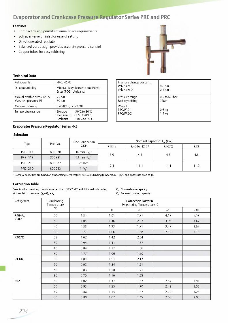
http://holodko.ru/
Evaporator and Crankcase Pressure Regulator Series PRE and PRCFeatures• Compact design permits minimal space requirements• Schrader valve on inlet for ease of setting• Direct operated regulator• Balanced port design provides accurate pressure control• Copper tubes for easy soldering
Technical Data
Refrigerants HFC. HCFCOil compatibility Mineral, Alkyl Benzene and Polyol-
Ester (POE) lubricantsMax. allowable pressure PS 25 barMax. test pressure PT 30 barMaterial. housing CW509L (EN12420)Temperature range Storage -30°C to 80°C
Medium TS -30°C to 80°C Ambient -30°C to 80°C
Pressure change per turn:Valve size 1 0.6 barValve size 2 0.4 bar
Pressure range 0.5 to 6.9 barFactory setting 2 barWeight:PRC/PRE-1.. 0.6 kgPRC/PRE-2.. 1.3 kg
Evaporator Pressure Regulator Series PRE
Selection
Type Part No. Tube Connection ODF
Nominal Capacity* Qn (kW)R134a R404A / R507 R407C R22
PRE - 11A 800 380 16 mm - 5/8”3.0 4.5 4.5 4.8
PRE - 11B 800381 22 mm - 7/8”
PRE - 21C 800382 28 mm7.4 11.1 11.1 11.9
PRE - 21D 800 383 1 -78”*Nominal capacities are based on evaporating Temperature +4°C, condensing temperature +38°C and a pressure drop of 1K.
Correction TableSelection for operating conditions other than +38°C/+4°C and 1 K liquid subcooling Qn: Nominal valve capacityat the inlet of the valve: Qn = Q0 x Kt Qo: Required cooling capacity
Refrigerant CondensingTemperature
°C
Correction Factor KEvaporating Temperature °C
10 0 -10 -20 -30
R404A / 60 1.35 1.91 2.77 4.18 6.53R507 50 1.05 1.46 2.07 3.05 4.62
40 0.88 1.22 1.71 2.48 3.6930 0.77 1.06 1.48 2.12 3.13
R407C 55 1.02 1.42 2.0450 0.94 1.31 1.8740 0.84 1.17 1.6630 0.77 1.06 1.50
R134a 60 1.04 1.51 2.1750 0.92 1.34 1.91
40 0.83 1.20 1.7130 0.76 1.10 1.55
R22 60 1.02 1.37 1.87 2.67 3.9150 0.93 1.25 1.70 2.42 3.5340 0.86 1.15 1.57 2.22 3.2330 0.80 1.07 1.45 2.05 2.98
234

http://holodko.ru/
Crankcase Pressure Regulator Series PRCSelection
Type Part No. Tube Connection ODF
Nominal Capacity* Qn (kW)R134a R404A / R507 R407C R22
PRC - 11A 800384 16 mm - 5/8”3.0 4.5 4.5 4.8
PRC - 11B 800 385 22 mm - 7/8”
PRC - 21C 800386 28 mm7.4 11.1 11.1 11.9PRC - 21D 800 387 1 J /8”
PRC - 21C 800388 35 mm - 1-3/8”
*Nominal capacities are based on evaporating temperature +4°C and condensing temperature +38°C and a pressure drop of 1 K.
Capacity TableSelection for operating conditions other than +38°C / +4°C and 1 K liquid subcooling at the inlet of the valve: (capacities are based on a pressure drop of 0.07 bar).
RefrigerantEvaporating
Temperature°C
Capacity (kW) Valve setting °C
Valve Size 1: PRC-11x Valve Size 2: PRC-21x-20 -15 -10 -5 0 5 10 -20 -15 -10 -5 0 5 10
R22
-29 2.3 3.4 4.4 4.8 4.9 5.8 8.8 10.0 10.0 10.0-21 2.4 4.1 5.4 5.8 6.5 12.1 12.1 12.1-14 2.7 4.9 6.2 8.1 13.8 13.8-8 3.5 5.3 9.0 15.4-3 3.1 9.9
R407 C-6 3.1 4.8 7.9 13.9
-1 2.9 9.2
R134 a-6 2.1 3.9 5.3 5.2 10.3 12.91 2.4 4.7 6.1 12.27 3.3 8.1
R404A / R507
-27 1.6 2.9 3.7 3.9 4.8 8.2 8.2 8.2-20 1.9 3.5 4.5 5.7 9.8 9.8-14 2.2 4.5 6.8 11.6
-10 3.1 8.1
235

http://holodko.ru/
236__—

http://holodko.ru/
Pressure Controls and Thermostats

http://holodko.ru/
Pressure ControlsBasic Terms and Technical Information
CharacteristicsPressure controls serve various functions, which may be divided into control and protection functions. Examples for control functions are compressor cycling, pump-down or defrost control. Protection functions include pressure limiting and cut out against excessive pressures, against loss of charge or for freeze protection. These functions are performed by operating a set of electrical contacts when exceeding a preset lower or upper pressure limit. Depending on whether they are type tested (TUV approved) or not they may be referred to by the following terms:
without TUV approval: Pressure Controlwith TUV approval: Pressure Limiter,
Pressure Cut Out or Safety Pressure Cut Out
Pressure controls with TUV approval are tested according to EN 12263 as required by DIN 8901 and EN 378.
1. Pressure controls (without TUV approval)Pressure controls without type approval may either be of the automatic or manual reset type. Manual reset versions are available for decreasing (manual reset min.) or increasing pressure (manual reset max.).
2. Pressure limiters PSL/PSHPressure limiters are of the automatic reset type. Limiters for high pressure applications have a double bellows design to act as fail-safe controls.
Upper switching point - Differential =Lower switching point
Pmax—Ap = Pmin
Function of contacts SPDTOn pressure rise above setting 1-2 opens and 1-4 closes. On pressure drop below setting 1 -2 closes and 1 -4 opens.
0 — 41 — 0 ^
The formula is:
SPDT with manual reset max.On pressure rise above setting 1-2 opens and 1-4 closes and latches. The device can be manually reset when the pressure has dropped below setting.
0 — 41 — 0 ^
3. Pressure cut outs PZH/PZLPressure cut outs are of the manual reset type where reset is possible from the outside of the control without the need for a tool (external reset). Cut outs for high pressure applications have a double bellows design to act as fail-safe controls.
SPDT with manual reset min.On pressure drop below setting 1-2 closes, 1-4 opens and latches. The device can be manually reset when the pressure has risen above setting.
4. Safety pressure cut outs PZHH/PZLLPressure cut outs are of the manual reset type where the reset requires the use of a tool. Typically, the removal of a cover is required in order to press the reset button (internal reset). Cut outs for high pressure applications have a double bellows design to act as fail-safe controls.
Adjustment of switching pointsA pressure gauge should always be used for comparison when adjusting the switching points on pressure controls. The setting scale on the device is intended to serve for orientation, showing the setting range of the upper switching point pmax in bar/psig and the value of the pressure differential Ap as difference between upper switching point pmax and the lower switching point pmin. The upper switching point pmax has to be adjusted on the scale, whereas the lower switching point pmin is given by adjustment of the desired switching differential Ap.
4
m t :
Unit of pressureAll pressures are given in gauge pressure
P . l t = P + 1barabsolute gauge
1 bar = 100 kPa 1 bar = 14.5 psi
Pulsation dampingAll high pressure controls with A-connection (7/16-20UNF. %” SAE male) are equipped with a snubber to protect the pressure element from pulsations.
238

http://holodko.ru/
Standards and Regulations
BGV D4 (VBG20) Accident prevention regulations for refrigeration plant.Heat pumps with fluorocarbon refrigerants. Protection of soil, underground and surface water. Specifications for low-voltage switchgear.Refrigerating systems and heat pumps - Safety and environmental requirements.Refrigerating systems and heat pumps - Safety switching devices for limiting the pressure requirements and tests.
Selection Guide for Pressure Controls
Series
Selection Criteria
Catalogue PageDesign Number of
Contacts (SPDT) AdjustableProtection DIN 40050
IEC 529
Rated Operational Current at 230 V AC
Inductive Amp. AC 15
Motor Rating UL
PS1 Standard Model 1 yes IP 44 10 A 24 A 240
PS2 Dual Pressure Switch 1 + 1 yes IP 44 10 A 24 A 242
PS3 Pressure Switch Standard-Types 1 Factory set to
fixed values IP 30 / IP 65 3 A 6 A 244
PS3 Pressure Switch OEM-Types 1
Fixed values acc.to customer
spec. depending on volume
IP 30 / IP 65 3 A 6 A 246
FD 113 Differential Pressure Switch 1
yespressure diff. +
time delayIP 30 3 A / 6 A - 247
DIN 8901
EN 60947-1/ EN 60947-5-1 EN 378
EN 12263:
239

http://holodko.ru/
Pressure Controls Series PS1 / PS2
Features• Adjustable pressure range• Automatic and manual reset versions• Flare and solder connections• Shatter resistant contacts• High operational current, locked rotor max. 144 Amps
(LRA)• Standard SPDT with same operational current rating for
both contacts• Dual pressostat with two separate SPDT for high and low
pressure side• Including sealable blocking plate and mounting screws
Options• Convertible reset to reduce stock• Further pressure connections• Factory set to customer specification
PS2 PS1
Standards
per Low Voltage Directive
• f £ per PED Directive 97/23 EG. TUV appr.versions only
• Manufactured and tested to standards on our own responsibility
• c© us usted Underwriter Laboratories
• German Lloyd for use on ships, when equipped with marine-type cable gland
Technical Data PS1 / PS2
Type of Contacts 1 SPDT for PS12 separate SPDT for PS2
Inductive Amp. (AC15) Inductive Amp. (DC13)
10 A / 230V AC 0.1 A / 230V DC
Motor Rating, Full Load Amp. Motor Rating, Locked Rotor Amp.
24 A / 120/240V AC 144 A / 120/240V AC
Protection acc. DIN 40050 / IEC 529 IP 44
Ambient Temperature RangeMax. Temperature at Pressure Connection
-50°C .. +70°C +70°C
Vibration Resistance (10 to 1000 Hz) 4 gCable Entry Grommet PG 16Locking Device Blocking PlateMounting Screws M4 / UNC 8-32
Single Pressure Controls PS1
Type Part No.
Adjustment RangeLowest
Setpointbar
FactorySetting
bar
Leakage Test Pressure
bar
PressureConnection
UpperSetpoint
bar
Differentialbar
Low Pressure ControlsPS1-A3A 4 370 700
LQo
5
LQo
-0.9 3.5 / 4.5 24
V - 2 0 UNF
PS1-A3K 4 370 600 capillary/nut
PS1-A3L 4 714 945 cap./solder
PS1-A3U 4 712 201 solder 6 mm
PS1-A3X 4 713 430 solder 1/4“
PS1-R3A 4350100
LQo
external reset
approx. 1 bar above
setpoint
-0.9 3.5 24
V - 2 0 UNF
PS1-R3K 4 713 431 capillary nut
High Pressure ControlsPS1-A5A 4 350 500
316 52 3 16 / 20 35
V - 2 0 UNF
PS1-A5K 4 370 400 capillary nut
PS1-A5L 4715136 cap./solder
PS1-A5U 4713325 solder 6 mm
PS1-A5X 4 713 434 solder 1/4“
PS1-R5A 4 350 700
316
ext. manual reset low
approx. 3 bar under setpoint
- 20 35
V - 2 0 UNF
PS1-R5K 4 370 300 capillary nut
PS1-R5X 4 713 436 solder 1/4“
240

http://holodko.ru/
Single Pressure Controls Series PS1 TUV / EN 1226 3
Adjustment Range Lowest Factory Leakage Test PressureConnectionType Part No. Upper Setpoint
barDifferential
barSetpoint
barSetting
barPressure
bar
Pressure Limiter for Low Pressure Protection PSL - Automatic Reset
PS1-W3A 4 368 300 7/16”-20 UNF
PS1-W3K 4 321 400 7.5-0. 5.50. -0.9 3.5 / 4.5 24 capillary/nutPS1-W3U 4713437 solder 6 mmPressure Cut Out for Low Pressure Protection PZL - External Reset
PS1-B3A 4 470 400 7/,6”-20 UNFPS1-B3U 4 715 141 7.5-0. approx. 1 bar -0.9 3.5 24 solder 6 mm
above setpoint
Pressure Limiter for High Pressure Protection PSH - Automatic Reset
PS1-W5A 4 353 200 7/,6”-20 UNF
PS1-W5K 43591006 ... 31 2 ... 15 3 16 / 20 35
capillary/nut
PS1-W5L 4 715 143 cap./solder
PS1-W5U 4 713 439 solder 6 mm
Pressure Cut Out for High Pressure Protection PZH - External Manual Reset
PS1-B5A 4 353 300 7/,6”-20 UNF
PS1-B5L 4 715 1446 ... 31
external reset approx. 3 bar
under setpoint20 35
cap./solder
PS1-B5U 4712332 solder 6 mm
PS1-B5X 4 713 441 solder 1/4“
Safety Pressure Cut Out for High Pressure Protection PZHH - Internal Manual Reset
PS1-S5A 4 368 400 7/,6”-20 UNF
PS1-S5L 4 715 1456 ... 31
internal reset approx. 3 bar
under setpoint21 35
cap./solder
PS1-S5U 4711 591 solder 6 mm
PS1-S5X 4 713 442 solder 1/4“
241

http://holodko.ru/
Dual Pressure Controls Series PS2
PS2
Adjustment Range Leakage Test
Upper Setpoint Factory SettingPressure
PressureConnectionType Part No.
left bar right bar left bar right barleft bar right bar
left bar right barCombined Low and High Pressure Controls
PS2-A7A 4 353 400 V - 2 0 UNFPS2-A7K 4 350 900 capillary/nutPS2-A7L 4713565 7.5-0. 6 ... 31 5
LH0. ca. 4 fix 3.5 / 4.5 20 24 35 cap./solderPS2-A7U 4 713 415 solder 6 mm
PS2-A7X 4 713 416 solder 1/4”
PS2-L7A 4 351 100 external 7/16”-20 UNF
PS2-L7K 4 370 500
7.5-0. 6 ... 31 5
LO0.
reset approx. 4 bar under
3.5 / 4.5 20 24 35capillary/nut
PS2-L7U 4 713 417 solder 6 mm
PS2-L7X 4 713 418 setpoint solder 1/4”
PS2-R7A 4 351 300 external reset
approx. 1 bar above setpoint
V -20 UNF
PS2-R7K 4 713 421 7.5-0. 6 ... 31 3.5 20 24 35 capillary/nut
PS2-R7U 4 713 419 solder 6 mm
Dual Pressure Controls Series PS2 TUV / EN 12263
Combined Pressure Limiter for Low Pressure / High Pressure Protection PSL / PSH - automatic / automatic
PS2-W7A 4360100 V -20 UNFPS2-W7K 4 450 200 capillary/nutPS2-W7L 4 450 300 7.5-0. 6 ... 31 0.5a) ... 5 ca. 4 fix 3.5 / 4.5 20 24 35 cap./solderPS2-W7U 4 712 436 solder 6 mm
PS2-W7X 4 713 429 solder 1/4”
Combined Pressure Limiter / Pressure Cut Out for Low Pressure / High Pressure Protection PSL / PZH - automatic / external manual reset
PS2-C7A 4 353 500external
reset
V -20 UNFPS2-C7K 4 348 400 capillary/nutPS2-C7L 5 715 131 7.5-0. 6 ... 31 0.5a) ... 5 approx. 4 3.5 / 4.5 20 24 35 cap./solder
PS2-C7U 4 713 422 bar under setpoint solder 6 mm
PS2-C7X 4 713 423 solder 1/4”
Combined Low and High Pressure Controls. High Side Convertible From Automatic to Manual Reset
PS2-M7A 4 361300 -0.5 .. 7 6 ... 31 0.5a ... 5 - 3,5 / 4,5 21 24 35 V -20 UNF
Combined Pressure Limiter Safety Pressure Cut Out for low pressure / high pressure protection EN 12263 PSL / PZHH (automatic / automatic convertible to external manual reset)PS2-N7A 4 715 756 -0.5 .. 7 6 ... 31 0.5a ... 5 - 3,5 / 4,5 21 24 35 7/16”-20 UNF
a) lowest possible setpoint: -0.9 bar
242—

http://holodko.ru/
Dual Pressure Controls PS2 TUV / EN 12263Adjustment Range Leakage Test
Upper Setpoint Factory SettingPressure
PressureConnectionType Part No.
left bar right bar left bar right barleft bar right bar
left bar right bar
Combined Pressure Limiter / Safety Pressure Cut Out for Low Pressure / High Pressure Protection PSL / PZHH - automatic / internal manual reset
PS2-T7A 4 368 500-0.5 . 7 6 . 31 0.5a) ... 5
external reset
approx. 4 bar under setpoint
3.5 / 4.5 20 24 35V - 2 0 UNF
PS2-T7U 4 713 424 solder 6 mm
Combined Pressure Cut Out for Low Pressure / High Pressure Protection PZL / PZH external manual reset / external manual reset
PS2-B7A 4 360 200
7
LJ1-0. 6 ... 31
external reset
approx. 1 bar above setpoint
external reset
approx. 4 bar under setpoint
3.5 20 24 35
V -20 UNFPS2-B7K 4 446 600 capillary/nutPS2-B7L 4 446 700 cap./solder
PS2-B7U 4 449 400 solder 6 mm
Combined Pressure Cut Out / Safety Pressure Cut Out for High Pressure Protection PZH / PZHH external manual reset / internal manual reset
PS2-G8A 4 368 600 external external V -20 UNFPS2-G8K 4 445 500
6 ... 31 6 ... 31reset
approx. 4 bar under
reset approx. 4 bar under
20 21 35 35capillary/nut
PS2-G8U 4 713 427 solder 6 mm
PS2-G8X 4 713 428 setpoint setpoint solder 1/4”
a) lowest possible setpoint: -0.9 bar
Accessories
Mounting bracket angle
Part No.: 803 799
<0
Mounting plate for units with hoodPart No.: 803 801
12,5
04,5
M 4
Extension bracketPart No.: 803 800
65
41
Universalmounting
bracketPart No.: 803 798
7/i6”-20 UNF -
= H = C t
Capillary Tube with two flare nuts 7/16”-20 UNF. R 1/4"
1.5m Part No.: 803 804
Copper Gasket Set for R 1/4 ‘ (7/16”-20 UNF. female)
100 pcs package Part No.: 803 780
243
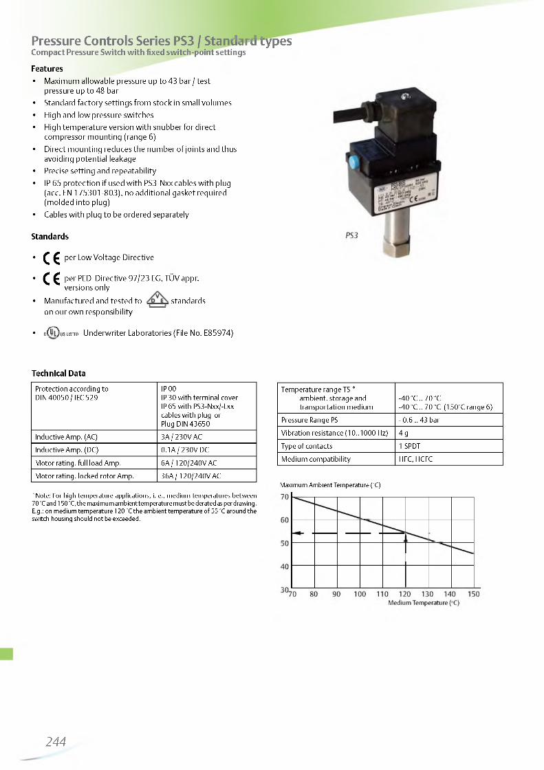
http://holodko.ru/
Pressure Controls Series PS3 / Standard typesCompact Pressure Switch with fixed switch-point settings
Features• Maximum allowable pressure up to 43 bar / test
pressure up to 48 bar• Standard factory settings from stock in small volumes• High and low pressure switches• High temperature version with snubber for direct
compressor mounting (range 6)• Direct mounting reduces the number of joints and thus
avoiding potential leakage• Precise setting and repeatability• IP 65 protection if used with PS3-Nxx cables with plug
(acc. EN 175301-803), no additional gasket required (molded into plug)
• Cables with plug to be ordered separately
Standards
• C € per Low Voltage Directive
• C C per PED Directive 97/23 EG, TUV appr.versions only
• Manufactured and tested to standardson our own responsibility
• c^Oususrai Underwriter Laboratories (File No. E85974)
Technical Data
Protection according to DIN 40050 / IEC 529
IP 00IP 30 with terminal cover IP 65 with PS3-Nxx/-Lxx cables with plug or Plug DIN 43650
Inductive Amp. (AC) 3A/ 230V ACInductive Amp. (DC) 0.1A / 230V DC
Motor rating. full load Amp. 6A / 120/240V ACMotor rating. locked rotor Amp. 36A / 120/240V AC
*Note: For high temperature applications, i. e., medium temperatures between70 °C and 150 °C, the maximum ambient temperature must be derated as per drawing. E.g.: on medium temperature 120 °C the ambient temperature of 55 °C around the switch housing should not be exceeded.
Temperature range TS * ambient. storage and transportation medium
-40 °C .. 70 °C-40 °C .. 70 °C (150°C range 6)
Pressure Range PS - 0.6 .. 43 barVibration resistance (10..1000 Hz) 4 gType of contacts 1 SPDTMedium compatibility HFC, HCFC
Maximum Ambient Temperature (oC)
244
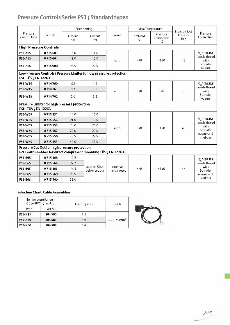
http://holodko.ru/
Pressure Controls Series PS3 / Standard types
Pressure Control Type Part No.
Fixed setting
Reset
Max. TemperatureLeakage Test
Pressure bar
PressureConnectionCut out
barCut out
barAmbient
°C
PressureConnection
°C
High Pressure ControlsPS3-A6S 0715603 16.0 11.0
auto +70 + 150 48
7/,6”-20UNF female thread
with Schrader opener
PS3-A6S 0715604 19.0 15.0
PS3-A6S 0715600 26.5 22.5
Low Pressure Controls / Pressure Limiter for low pressure protection PSL TUV / EN 12263PS3-W1S 0714760 -0.3 1.2
auto +70 +70 30
7/,6”-20UNF female thread
with Schrader opener
PS3-W1S 0 714 761 0.3 1.8
PS3-W1S 0 714 762 2.0 3.5
Pressure Limiter for high pressure protection PSH TUV / EN 12263PS3-W6S 0 715 831 14.0 10.0
auto +70 + 150 48
7/,6”-20UNF female thread
with Schrader
opener and snubber
PS3-W6S 0715556 21.0 16.0PS3-W6S 0715555 25.0 20.0PS3-W6S 0715567 29.0 23.0PS3-W6S 0715550 33.5 27.5PS3-W6S 0715553 40.0 33.0
Pressure Cut Out for high pressure protectionPZH with snubber for direct compressor mounting TUV / EN 12263PS3-B6S 0715568 19.2
approx. 5 bar below cut-out
external manual reset +70 + 150 48
7/,6”-20UNF female thread
with Schrader
opener and snubber
PS3-B6S 0715564 22.7PS3-B6S 0715563 27.3PS3-B6S 0715569 29.5PS3-B6S 0715560 36.0
Selection Chart Cable Assemblies
Temperature Range -50 to 80°C / no UL Length (mtr.) LeadsType Part No.
PS3-N15 804 580 1.53 x 0.75 mm2PS3-N30 804 581 3.0
PS3-N60 804 582 6.0Eo
245

http://holodko.ru/
Pressure Controls Series PS3 / Special TypesFor OEM use with settings according to customer’s specification,minimum order quantity 100 pcs.
Features• Maximum allowable pressure up to 43 bar / test pressure up
to 48 bar• For direct mounting on a pressure connection (free standing)
or with a capillary tube• Direct mounting reduces the number of joints and thus
avoiding potential leakage• Direct mounting saves cost for flexible hose and additional
fittings• Precise setting and repeatability• High temperature version with snubber, for direct compressor
mounting (range 6)• Micro switch for narrow pressure differentials• Gold plated contacts for low voltage / current applications• Worldwide approvals• Easy mounting
Options• Low pressure switch with automatic or manual reset• High pressure switch with automatic or manual reset,
standard or high temperature version• Pressure limiter PSH - standard or high temperature version• Pressure cut-out PZH - external reset, standard or high
temperature version• Safety pressure cut-out PZHH - internal reset, standard or
high temperature version
Electrical connections (optional)• Cables with plug in lengths of 1.5m, 3.0m and 6.0m available.
No additional gasket required.• Appliance socket DIN 43650
Type of contacts (optional)• Standard (SPDT)• Micro switch (SPDT)• Gold plated contacts upon request
Standards
• C € per Low Voltage Directive
• C C per PED Directive 97/23 EG. TUV appr.versions only
• Manufactured and tested to standards onour own responsibility
• c ( 5 l ) u s usteo Underwriter Laboratories (File No. E85974)
Pressure connections• S: 7/16” -20UNF, female w ith Schrader opener and snubber
(snubber only with high temperature diphragm)• A: 7/16”- 20UNF, 1/4” SAE male• U: 6 mm solder. 80 mm length. ODF• X : 1/4” solder. 80 mm length. ODF• K: 1 m capillary tube with 1/4” SAE flare nut and Schrader opener• L: 1 m capillary tube and 1/4” ODM solder connector
Installation• Depending on pressure connection, free-standing or with
console.
Technical Data
Protection according to DIN 40050 / IEC 529
IP 00IP 30 with terminal cover IP 65 with PS3-Nxx cables with plug or Plug DIN 43650
Inductive Amp. (AC15) 3 A / 230V AC1.5 A with microswitch standard 0.1 A with gold plated contacts
Inductive Amp. (DC) 0.1 A / 230V DCMotor rating, full load Amp. 6 A / 120/240V AC
2.5 A with microswitchMotor rating, locked rotor Amp. 36 A / 120/240V AC
15 A with microswitch
Temperature range TSAmbient. storage and transportationMedium
-40°C ... 70°C-40°C ... 70°C (150°C range 6)
Pressure Range PS - 0.6 .. 43 barVibration resistance (10..1000 Hz) 4 g (10 to 1000 Hz)Type of contacts 1 SPDT
Medium compatibility HFC, HCFCAvailable approvals TUV, ULWeight (approx.) 0.1 kg
For more information see datasheet PS3_e35003.
246

http://holodko.ru/
Differential Pressure Controls Series FD 113Features• Immediate reset (no cooling down period)• Precise timing• Adjustable time delay from 20 to 150 sec (ZU types)• Separate output signals for operation and alarm• Suitable for supply voltage 24 to 240 V AC / DC• Pressure connection: Flare 7/16“-20 UNF, : /4“ SAE male
Standardsper Low Voltage Directive
r yO. 1 F D 1 1 3• Manufactured and tested to / o _ r \ standards on our I
own responsibility
• C 0 U S LISTED File No. E85974
Differential Pressure Controls Type
Part No.
Time Delay Cut outCut in Fixed
Setting
Max.Differential
Pressure
Max. Proof PressureAdjustable Factory
SettingAdjusting Range Ap
FactorySetting
Sec. Sec. bar bar bar bar bar
FD 113 0710173 - -0.3 ... 4.5 0.7 0.2 above
cut- out
-0.8 ... 12 25
FD 113 ZU 3 465 300 20 ... 150 120FD 113 ZU (A22-057)Copeland®brandproducts
0711 195 - 115 fix - 0.63 fix appr. 0.9
Technical Data
Inductive Amp. (AC) 3.0 A / 230 V AC
Inductive Amp. (DC) 0.1 A / 230 V DCProtection acc. to EN 60 529 IP 30Nominal Voltage FD 113 ZU 24 ... 240V AC / DC
Ambient Temperature Range -20°C to +70°C
Max. Temperature at Pressure Connection +70°C
Vibration resistance (10 to 1000 Hz) 4 g
Accessories
Mounting bracket angle
Part No.: 803 799
Mounting plate for units with hoodPart No.: 803 801
Extension bracketPart No.: 803 800
7/ie”-20 UNF -
=H = = C t
Capillary Tube with two flare nuts 7/16”-20 UNF. R 1/4“
1.5m Part No.: 803 804
Copper Gasket Set for R 1/4“ (7/16”-20 UNF. female)
100 pcs package Part No.: 803 780
247
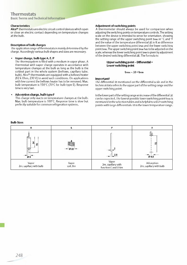
http://holodko.ru/
ThermostatsBasic Terms and Technical Information
CharacteristicsAlco® thermostats are electric circuit control devices which open or close an electric contact depending on temperature changes at the bulb.
Description of bulb chargesThe application range of thermostats is mainly determined by the charge. Accordingly various bulb shapes and sizes are necessary.
• Vapor charge, bulb type A. E. PThe thermosystem is filled with a medium in vapor phase. A thermostat with vapor charge operates in accordance with temperature changes at the bulb as long as the bulb is the coldest part in the whole system (bellows, capillary tube, bulb). Alco® thermostats are equipped with a bellows heater (82 k Ohm, 230 V) to avoid such conditions. On applications with low current the bellows heater has to be removed. Max. bulb temperature is 150°C (70°C for bulb type E). Response time is very fast.
• Adsorption charge, bulb type FThis charge only reacts on temperature changes at the bulb. Max. bulb temperature is 100°C. Response time is slow but perfectly suitable for common refrigeration systems.
Adjustment of switching pointsA thermometer should always be used for comparison when adjusting the switching points on temperature controls. The setting scale on the device is intended to serve for orientation, showing the setting range of the upper switching point tmax in °C and °F and the value of the temperature differential At in K as difference between the upper switching point tmax and the lower switching point tmin. The upper switching point tmax has to be adjusted on the scale, whereas the lower switching point tmin is given by adjustment of the desired switching differential A t. The formula is:
Upper switching point - Differential = Lower switching point
tmax — At = tmin
Important!The differential At mentioned on the differential scale and in the technical data refers to the upper part of the setting range and the upper switching point.
In the lower part of the setting range an increase of the differential At can be expected. The lowest possible lower switching point tmin is mentioned in the selection tables and is helpful to select switching points with large differentials At in the lower temperature range.
Bulb Sizes
2
2,5
k
0 9,5
Vapor 2m, capillary with
function C and D 6m
Adsorption 2m, capillary with bulb
1
f0 9
Vapor 2m, capillary with bulb
Vapor coil, 0m
A E P F
248

http://holodko.ru/
Function of Contacts
0 — 4
SPDT- On temperature rise above setting
1 -2 opens and 1 -4 closes.- On temperature drop below setting
1 -2 closes and 1 -4 opens.
0 — 4
Ht:SPDT with manual reset min.- On temperature drop below setting
1 -2 closes. 1 -4 opens and latches.- The device can be manually reset when
the tem perature has risen at least 2K above setting.
1_0̂ 0̂ 2H i!
SPDT with manual reset max.- On temperature rise above setting
1 -2 opens and 1 -4 closes and latches.- The device can be manually reset when
the temperature has dropped 2K below setting.
0 — 4
SPDT with off switch AUTO m atic - STOP
O--E l l
SPDT with bellows heatincludes a 82 k O hm , 230 resistor
— 4
— 2
erV AC/DC
Standards and regulationsImportant for the installation of thermostats:
EN 60730-2-9
EN 60947-1/ EN 60947-5-1
Specification for temperature controls and temperature cut-outs.
Specifications for low-voltage switchgear.
EN 378: Refrigerating systems and heat pumps. Safetyand environmental requirements.
249

http://holodko.ru/
Thermostats Series TS1Features• Adjustable temperatures and differentials• Shatter resistant contacts• High operational current, locked rotor max. 144 Amps (LRA)• Standard SPDT with same operational current rating for both
contacts• Captive terminal and cover screws• Range and differential individually lockable
Technical Data
Type of Contacts 1 SPDTInductive Amp. (AC15) 10 A / 230 V ACInductive Amp. (DC13) 0.1 A / 230 V DCHeating load (AC1) 24 A / 230 V ACMotor Rating, Full Load Amp. 24 A / 120/240V ACMotor Rating, Locked Rotor Amp. 144 A / 120/240V ACAmbient Temperature Range -50°C to +70°CVibration Resistance (10 to 1000 Hz) 4 gCable Entry Grommet PG 16Protection acc. to DIN 40050 / IEC 529
IP 44(IP 30 with Selector Switch)
Bellows Heater at Vapor Charge 82 K Ohm. 230 V AC / DC (12 and 24 V DC upon request)
TS1 Flush M ounted
<“ >
TS1 Top Operated
TS1 Front Operated
Standards
• ( € per Low Voltage Directive
• Manufactured and tested to standards on our own responsibility
• c(^ us listed Underwriter Laboratories
Adjustment RangeLowest
SetpointFactorySetting
Max. Bulb Temp.
Temperature Sensor
Type Part No. UpperSetpoint
Differential Setpoint AT Charge Cap. tube
length°C K °C °C °C
Thermostats Top OperatedThermostats without Off-Switch
TS1-A2P 4 530 400 -30 ... +15 1.5 ... 16 -36 -1 / -6+ 150 Vapor 2m capillary
TS1-A3P 4 356 700 -10 ... +35 1.5 ... 16 -23 +3 / -2
TS1-A1A 4 351 500 -45 ...-10 1.5 ... 16 -55 -18 / -20
TS1-A2A 4 351 600 -30 ... +15 1.5 ... 16 -36 -1 / -6 + 150 Vapor
TS1-A3A 4 352 500 -10 ... +35 1.5 ... 16 -23 +3 / -2
TS1-A4FDefrost- andUniversalTherm ostat
4 351 800 -30 ... +35 2.8 ... 20 -35 +5 / 0+ 100 Adsorption
2m capillary and bulb
TS1-A5F 4 458 400 +20 ... +60 3 ... 10 + 10 +35/+30Thermostats with Off-Switch
TS1-B1A 4 366 700 -45 ...-10 1.5 ... 16 -55 -18 / -20
TS1-B2A 4 366 800 -30 ... +15 1.5 ... 16 -36 -1 / -6 + 150 Vapor 2m capillaryTS1-B3A 4 366 900 -10 ... +35 1.5 ... 16 -23 +3 / -2 and bulb
TS1-B4F 4 367 000 -30 ... +35 2.8 ... 20 -35 +5 / 0 + 100 Adsorption
Frost Monitors Top OperatedFrost Monitors without Off-SwitchTS1-C0P 4352100 +4.5 ... +20 2.5 fix +2 4.5 / +2
TS1-D0PLow tem p. cut out
4 352 200 +4.5 ... +20 man. reset ca. 2.5 fix +2 +2
+ 150 Vapor 6m capillary
250

http://holodko.ru/
Adjustment RangeLowest
SetpointFactorySetting
Max. Bulb Temp.
Temperature Sensor
Type Part No. UpperSetpoint
Differential Setpoint AT Charge Cap. tube
length°C K °C °C °C
Room Thermostats Top OperatedRoom Thermostats without Off-Switch, including insulation consoleTS1-A1E 4 362 800 05-4 -55 -18 / -20
0mcoilTS1-A2E 4 355 200 -30 ... +15 1.5 ... 16 -36 +4 / +2 +70 Vapor
TS1-A3E 4 355 300 -10 ... +35 -23 +20/+18Room Thermostats with Off-Switch, including insulation console
TS1-B2E 4 344 400 -30 ... +151.5 ... 16
-36 +4 / +2+70 Vapor 0m
TS1-B3E 4 344 500 -10 ... +35 -23 +20/+18 coil
Thermostats Front OperatedThermostats without Off-Switch
TS1-E1A 4 361 000 05-4 2 ... 16 -55 -18 / -20
TS1-E2A 4 356 200 -30 ... +10 1.5 ... 15 -36 +4 / +2 + 150 Vapor
TS1-E3A 4 365 200 -10 ... +25 1.5 ... 15 -23 +3 / -2TS1-E4FDefrost- and universal therm ostat
4 367 500 -25 ... +30 02002. -30 +5 / 0 2m capillary
and bulb
TS1-E5F 4338100 +20 ... +60 3 ... 10 + 10 +35/+30 + 100 AdsorptionTS1-E7FMilk and beer cooler therm ostat
4 367 600 +0 ... +10 2.5 fix -2.5 +5.5 / +3
Thermostats with Off-Switch
TS1-F1A 4367100 05-4 2 ... 16 -55 -18 / -202m capillary
and bulbTS1-F2A 4 367 200 -30 ... +10 1.5 ... 15 -36 -1 / -6 + 150 Vapor
TS1-F3A 4 367 400 -10 ... +25 1.5 ... 15 -23 +3 / -2
Room Thermostats Front OperatedRoom Thermostats without Off-Switch, including insulation consoleTS1-E1E 4 365 300 05-4 2 ... 16 -55 -18 / -20
0mcoilTS1-E2E 4 356 800 -30 ... +10 1.5 ... 15 -36 +4 / +2 +70 Vapor
TS1-E3E 4 356 900 -10 ... +25 1.5 ... 15 -23 +20/+18Room Thermostats with Off-Switch, including insulation consoleTS1-F1E 4 368 000 05-4 2 ... 16 -55 -18 / -20
0mcoilTS1-F2E 4368100 -30 ... +10 1.5 ... 15 -36 +4 / +2 +70 Vapor
TS1-F3E 4 368 200 -10 ... +25 1.5 ... 15 -23 +20/+18
Thermostats for Flush MountingThermostats for Flush Mounting without Off-Switch
TS1-G2A 4 355 400 -30 ... +15 1.5 ... 15 -36 +4 / +2+ 150 Vapor
TS1-G3A 4 364 800 -10 ... +35 1.5 ... 15 -23 +20/+18TS1-G4FDefrost- and universal therm ostat
4 355 600 -30 ... +35 02002. -35 +5 / 0
+ 100 Adsorption
2m capillary and bulb
TS1-G7FMilk and beer cooler therm ostat
4 356 000 0 ... +10 2.5 fix -2.5 +5.5 / +3
Thermostats for Flush Mounting with Off-Switch
TS1-H1A 4 364 600 05-4 1.5 ... 15 -55 -18 / -20
TS1-H2A 4 355 500 -30 ... +15 1.5 ... 15 -36 -1 / -6 + 150 Vapor
TS1-H3A 4 367 900 -10 ... +35 1.5 ... 15 -23 +3 / +2 2m capillaryTS1-H4F 4 355 800 -30 ... +35 02
002. -35 +5 / 0 and bulb
TS1-H7FMilk and beer cooler therm ostat
4 365 500 0 ... +10 2.5 fix -2.5 +5.5 / 3+ 100 Adsorption
Thermostats for flush mounting are delivered with mounting angle Order No. 803 805.
251

http://holodko.ru/
Accessories & Spare Parts
Insulation Consolefor room thermostats standard
Part No.: 803 777
Capillary Tube Holderfor frost monitors standard
Part No.: 803 778
12,5^
04,5'
M4"
Mounting Bracket Angle
Part No.: 803 799
Mounting Platefor units with hood Part No.: 803 801
Extension Bracket
Part No.: 803 800
SW27
G VS'
1 Q 0 7
65
41
12C
Capillary Tube Gland. Brassfor bulb style A / C Part No.: 803 807
Universal Mounting Bracket
Part No.: 803 798
252

http://holodko.ru/
System Protectors and Moisture Indicators
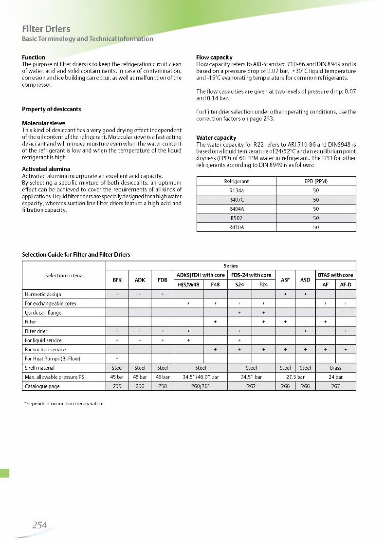
http://holodko.ru/
Filter DriersBasic Terminology and Technical Information
FunctionThe purpose of filter driers is to keep the refrigeration circuit clean of water, acid and solid contaminants. In case of contamination, corrosion and ice building can occur, as well as malfunction of the compressor.
Property of desiccants
Molecular sievesThis kind of desiccant has a very good drying effect independent of the oil content of the refrigerant. Molecular sieve is a fast acting desiccant and will remove moisture even when the water content of the refrigerant is low and when the temperature of the liquid refrigerant is high.
Activated aluminaActivated alumina incorporate an excellent acid capacity.By selecting a specific mixture of both desiccants, an optimum effect can be achieved to cover the requirements of all kinds of applications. Liquid filter driers are specially designed for a high water capacity, whereas suction line filter driers feature a high acid and filtration capacity.
Selection Guide for Filter and Filter Driers
Selection criteria
Series
BFK ADK FDBADKS/FDH with core FDS-24 with core
ASF ASDBTAS with core
H/S/W48 F48 S24 F24 AF AF-D
Hermetic design + + + + +
For exchangeable cores + + + + + +
Quick cap flange + +
Filter + + + +
Filter drier + + + + + + +
For liquid service + + + + +
For suction service + + + + + + +
For Heat Pumps (Bi-Flow) +
Shell material Steel Steel Steel Steel Steel Steel Steel BrassMax. allowable pressure PS 45 bar 45 bar 45 bar 34.5*7 46.0* bar 34.5* bar 27.5 bar 24 barCatalogue page 255 256 258 260/261 262 266 266 267
*dependent on medium temperature
Flow capacityFlow capacity refers to ARI-Standard 710-86 and DIN 8949 and is based on a pressure drop of 0.07 bar, +30°C liquid temperature and -15°C evaporating temperature for common refrigerants.
The flow capacities are given at two levels of pressure drop: 0.07 and 0.14 bar.
For Filter drier selection under other operating conditions, use the correction factors on page 263.
Water capacityThe water capacity for R22 refers to ARI 710-86 and DIN8948 is based on a liquid temperature of 24/52°C and an equilibrium point dryness (Ep D) of 60 PPM water in refrigerant. The EPD for other refrigerants according to DIN 8949 is as follows:
Refrigerant EPD (PPM)R134a 50
R407C 50R404A 50R507 50
R410A 50
254

http://holodko.ru/
Features• Solid block style• Integrated check valves ensure Bi-flow capability, eliminate the need
for external check valves and reduce the external piping• ODF Copper fittings for easy soldering• Pattern flow for non-turbulent performance• High water, acid adsorption capacity• Temperature range TS: -40°C to +65°C• Max. allowable pressure PS: 45 bar• No CE marking according art. 3.3 PED 97/23 EC• HP marking according to German Pressorized Vessel Directive
Underwriter Laboratories
Bi-flow Filter Driers Series BFKHermetic Design for Liquid Refrigerants
Type Part No. Connection size & type
Nominal Flow Capacity (KW)
at 0.07 bar pressure drop at 0.14 bar pressure drop
R134a R22 R407C R404AR507 R410A R134a R22 R407C R404A
R507 R410A
BFK-052 007 343 1/4 “(6mm)SAE 5.2 5.7 5.4 3.7 5.6 8.0 8.8 8.4 5.7 8.7BFK-052S 007 344 1/4”ODF 6.8 7.3 7.0 4.8 7.2 10.1 11.1 10.6 7.2 10.9BFK-083 007 345 3/8 “(10mm)SAE 10.6 11.5 11.0 7.5 11.4 16.9 18.4 17.6 12.0 18.2BFK-083S 007 346 3/8”ODF 12.0 13.1 12.5 8.5 12.9 20.6 22.5 21.5 14.7 22.2BFK-084 007 347 1/2 “(12mm)SAE 15.2 16.6 15.8 10.8 16.4 25.8 28.1 26.8 18.3 27.8
BFK-084S 007 348 1/2”ODF 15.6 17.0 16.2 11.1 16.8 28.7 31.3 29.9 20.4 30.9BFK-163 007 349 3/8 “(10mm)SAE 13.6 14.9 14.2 9.7 14.7 21.0 22.9 21.8 14.9 22.6BFK-163S 007350 3/8”ODF 15.5 16.9 16.1 11.0 16.7 23.8 26.0 24.8 17.0 25.7BFK-164 007 351 1/2 “(12mm)SAE 20.3 22.1 21.1 14.4 21.9 27.5 30.0 28.6 19.6 29.6BFK-164S 007352 1/2”ODF 24.3 26.5 25.3 17.3 26.1 34.4 37.6 35.9 24.5 37.1BFK-165 007353 5/8 “(16mm)SAE 25.1 27.4 26.2 17.9 27.1 35.3 38.5 36.8 25.1 38.0BFK-165S 007354 5/8”ODF 25.6 28.0 26.7 18.3 27.6 37.0 40.4 38.5 26.3 39.9BFK-305S 007356 5/8”(16mm) ODF 34.1 37.3 35.6 24.3 36.8 52.8 57.7 55.0 37.6 56.9
BFK-307S 007357 7/8”(22mm) ODF 40.6 44.3 42.3 28.9 43.7 65.7 71.7 68.4 46.8 70.8BFK-309S 007358 1 1/8”ODF 47.0 51.3 49.0 33.5 50.7 79.9 87.2 83.2 56.9 86.1
The rated flow capacities are in accordance with ARI standard 710-86 and Selection method for other conditions:DIN 8949 at +30°C liquid temperature and -15°C evaporating temperature. 1. Determine the correction factor (page 263) based on type of
refrigerant, liquid and evaporating temperature.2. Multiply the correction factor by cooling capacity or heating capac
ity whatever is more.3. Select the filter drier according to determined capacity
corresponding to flow capacity at 0.07 bar pressure drop.
W ater and Acid Adsorption Capacity
Type
Water adsorption capacity (gram) Acid Adsorption Capacity (g)
Liquid Temperature 24 °C Liquid Temperature 52 °CR134a R22 R404A/R507 R407C R410A R134a R22 R404A/R507 R407C R410A
BFK-05... 4.4 4.1 4.5 3.4 2.8 4.1 3.8 4.3 2.8 2.2 0.3BFK-08... 9.6 9.0 9.9 7.5 6.2 8.9 8.2 9.4 6.0 4.7 0.6BFK-16... 18.9 17.7 19.5 14.8 12.2 17.5 16.2 18.5 11.9 9.3 1.2BFK-30... 34.5 32.3 35.6 27.1 22.4 31.9 29.6 33.7 21.7 17.0 2.0
255

http://holodko.ru/
Filter Driers Series ADKHermetic Design for Liquid Refrigerants
FeaturesRobust block with optimum blend of molecular sieve and activated aluminaODF Copper fittings for easy soldering High water and acid capacity Filtration down to 20 micron Temperature range TS: -40°C to +65°C Max. allowable pressure PS: 45 bar No CE marking according art. 3.3 PED 97/23 EC HP marking according to German Pressorized Vessel Directive
u s lb t fd Underwriter Laboratories
AD K
Type Part No.
Nominal Flow Capacity (kW) nom. Conditions see next page
at 0.07 bar pressure drop at 0.14 bar pressure drop
R22 R134a R404AR507 R407C R407F R410A R744 R22 R134a R404A
R507 R407C R407F R410A R744
ADK-032 003 595 7.3 6.7 4.8 7.0 7.0 7.2 10 .6 10 .6 9.7 6.9 10 .1 10 .2 10.5 15.4
ADK-036MMS 003 597 8.0 7.3 5.2 7.6 7.9 1 1 .6 12 .0 1 1 .0 7.8 11.4 1 1 .8 17.4
ADK-032S 003 596 8.8 8.1 5.7 8.4 8.5 8.7 12 .8 12.9 1 1 .8 8.4 12.3 12.4 12.7 18.8
ADK-052 003 598 7.6 6.9 4.9 7.2 7.3 7.5 1 1 .0 1 1 .0 10 .1 7.2 10.5 10 .6 10.9 16.0
ADK-056MMS 003 600 10 .0 9.2 6.5 9.5 9.9 14.5 15.0 13.7 9.8 14.3 14.8 2 1 .8
ADK-052S 003 599 10 .8 9.9 7.0 10.3 10.4 10.7 15.7 17.1 15.6 1 1 . 1 16.3 16.5 16.9 24.8
ADK-053 003 601 14.2 13.0 9.2 13.5 13.6 14.0 20.6 21.3 19.5 13.9 20.3 20.5 2 1 .0 31.0
ADK-0510MMS 003 603 16.4 15.0 10.7 15.6 16.1 23.8 24.1 2 2 .1 15.7 23.0 23.8 35.1
ADK-053S 003 602 16.4 15.0 10.7 15.6 15.8 16.1 23.8 24.1 2 2 .1 15.7 23.0 24.8 23.8 35.1
ADK-082 003 604 7.8 7.1 5.1 7.4 7.5 7.7 11.3 11.3 10.4 7.4 10 .8 10.9 1 1 . 2 16.4
ADK-086MMS 003 606 10.7 9.8 7.0 10 .2 10.5 15.5 16.0 14.7 10.4 15.3 15.8 23.3
ADK-082S 003 605 11.9 10.9 7.8 11.4 11.5 1 1 .8 17.4 17.3 15.9 11.3 16.5 16.7 17.1 25.2
ADK-083 003 607 16.4 15.0 10.7 15.6 16.0 16.2 23.8 23.9 21.9 15.6 2 2 .8 23.1 23.6 34.8
ADK-0810MMS 003 609 16.4 15.0 10.7 15.6 16.2 23.8 24.1 2 2 .1 15.7 23.0 23.8 35.0
ADK-083S 003 608 16.4 15.0 10.7 15.7 15.8 16.2 23.9 24.1 2 2 .1 15.7 23.0 23.3 23.8 35.1
ADK-084 003 610 25.7 23.5 16.7 24.5 24.7 25.3 37.3 39.1 35.8 25.5 37.3 37.7 38.6 56.9
ADK-0812MMS 003 612 26.3 24.1 17.2 25.1 26.0 38.3 39.5 36.2 25.8 37.7 39.0 57.4
ADK-084S 003 611 26.8 24.5 17.5 25.6 25.8 26.4 39.0 40.4 37.0 26.3 38.5 38.9 39.8 58.7
ADK-162 003 613 8.0 7.3 5.2 7.6 7.7 7.8 1 1 .6 11.5 10.5 7.5 10.9 1 1 .0 11.3 16.7
ADK-163 003 614 16.8 15.4 10.9 16.0 16.2 16.5 24.4 24.1 2 2 .1 15.7 23.0 23.3 23.8 35.1
ADK-1610MMS 003 616 18.7 17.1 12 .2 17.8 18.5 27.2 26.8 24.5 17.5 25.6 26.5 39.0
ADK-163S 003 615 18.7 17.2 12 .2 17.9 18.1 18.5 27.2 26.8 24.5 17.5 25.6 25.8 26.5 39.0
ADK-164 003 617 31.3 28.7 20.4 29.9 34.1 30.9 45.5 47.1 43.2 30.7 45.0 47.2 46.5 68.6
ADK-1612MMS 003 619 32.3 29.6 2 1 . 1 30.8 31.9 47.0 48.5 44.4 31.6 46.3 47.9 70.5
ADK-164S 003 618 36.0 33.0 23.5 34.3 35.1 35.5 52.3 49.9 45.7 32.6 47.6 48.1 49.3 72.6
ADK-165 003 620 44.8 41.1 29.2 42.8 43.2 44.3 65.2 66.5 60.9 43.4 63.5 64.1 65.7 96.7
ADK-165S 003 621 49.7 45.6 32.4 47.4 47.9 49.1 72.3 72.4 66.3 47.2 69.1 69.8 71.5 105.3
ADK-303 003 622 17.7 16.2 11.5 16.9 17.1 17.5 25.7 25.4 23.2 16.5 24.2 24.5 25.0 36.9
ADK-304 003 623 31.3 28.7 20.4 29.9 30.2 30.9 45.5 47.1 43.2 30.7 45.0 45.5 46.5 68.6
ADK-304S 003 624 36.0 33.0 23.5 34.4 34.7 35.6 52.4 51.6 47.2 33.6 49.2 49.7 50.9 75.0
ADK-305 003 626 52.6 48.2 34.3 50.2 50.7 52.0 76.6 72.1 66.0 47.0 68.7 69.5 71.1 104.8
ADK-305S 003 627 52.8 48.4 34.4 50.4 46.4 52.1 76.8 72.9 66.8 47.6 69.6 70.3 72.0 106.1
ADK-307S 003 628 66.3 60.7 43.2 63.2 63.9 65.4 96.4 104.6 95.8 68.2 99.8 10 0 .8 103.2 152.1
ADK-414 003 629 36.8 33.7 24.0 35.1 36.3 53.5 55.2 50.6 36.0 52.7 54.5 80.3
ADK-415 003 632 58.6 53.7 38.2 55.9 57.8 85.2 87.9 80.5 57.3 83.9 86.8 127.8
ADK-415S 003 633 63.0 57.7 41.1 60.1 62.2 91.6 94.5 86.6 61.6 90.2 93.3 137.4
ADK-417S 003 634 77.9 71.4 50.8 74.3 80.0 76.9 113.3 116.9 107.1 76.2 111.5 121.7 115.4 170.0
ADK-757S 003 635 105.5 96.7 68.8 100.7 1 2 2 .8 104.2 153.5 158.3 145.0 103.2 151.0 163.8 156.2 230.2
ADK-759S 003 636 117.2 107.4 76.4 1 1 1 . 8 133.9 115.7 170.4 175.8 161.0 114.6 167.7 173.2 173.5 255.6
256

http://holodko.ru/
Water and Acid Capacity
Size
Water adsorption capacity (gram) AcidAdsorption
Capacity(gram)
Liquid Temperature 24 °C Liquid Temperature 52 °C
R134a R22 R404A/R507 R407C R410A R134a R22 R404A/R507 R407C R410A
ADK-03 4.9 4.5 4.9 3.4 2.8 4.4 4.0 4.6 2.9 2.4 0.8
ADK-05 1 1 .8 10 .8 1 1 .8 8.2 6.8 10 .6 9.6 10.9 7.0 5.8 2.3
ADK-08 17.9 16.4 18.0 12.4 10.3 16.2 14.6 16.6 10.7 8.8 3.3
ADK-16 23.0 2 1 .0 23.1 16.0 13.2 20 .8 18.8 21.3 13.8 11.4 4.5
ADK-30 51.8 48.6 53.5 36.9 30.6 47.4 43.3 49.3 31.8 26.3 11.3
ADK-41 81.7 76.6 84.3 58.2 48.3 74.8 68.3 77.8 50.2 41.4 16.8
ADK-75 143.5 134.5 148.1 10 2 .1 84.8 131.4 12 0 .0 136.6 88.1 72.8 29.9
The water capacities are according to ARI-Standard 710 for R22 and are based on a equilibrium point dryness (EPD) of 60 PPM water in refrigerant. TheEPD for all other mentioned refrigerants according to DIN 8949 is 50 PPM.
Connections
Type Part No.
Connection
Solder/ODF Flare/SAE
mm inch mm inch
ADK-032 003 595 6 1/4ADK-036MMS 003 597 6
ADK-032S 003 596 1/4ADK-052 003 598 6 1/4ADK-056MMS 003 600 6
ADK-052S 003 599 1/4ADK-053 003 601 10 3/8
ADK-0510MMS 003 603 10
ADK-053S 003 602 3/8
ADK-082 003 604 6 1/4ADK-086MMS 003 606 6
ADK-082S 003 605 1/4ADK-083 003 607 10 3/8
ADK-0810MMS 003 609 10
ADK-083S 003 608 3/8
ADK-084 003 610 1 2 1 /2
ADK-0812MMS 003 612 1 2
ADK-084S 003 611 1 /2
ADK-162 003 613 6 1/4ADK-163 003 614 10 3/8
ADK-1610MMS 003 616 10
ADK-163S 003 615 3/8
ADK-164 003 617 1 2 1 /2
ADK-1612MMS 003 619 1 2
ADK-164S 003 618 1 /2
ADK-165 003 620 16 5/8
ADK-165S 003 621 5/8
ADK-303 003 622 10 3/8
ADK-304 003 623 1 2 1 /2
ADK-304S 003 624 1 /2
ADK-305 003 626 16 5/8
ADK-305S 003 627 5/8
ADK-307S 003 628 2 2 7/8
ADK-414 003 629 1 2 1 /2
ADK-415 003 632 16 5/8
ADK-415S 003 633 5/8
ADK-417S 003 634 2 2 7/8
ADK-757S 003 635 2 2 7/8
ADK-759S 003 636 1 -1 /8
Nominal Operating ConditionsNominal capacity is based on the following conditions:
Refrigerant Evaporatingtemperature
Liquidtemperature
R744 -40°C -10°CR22, R134a,R404A,R407C, R407F R410A,R507
-15°C +30°C
Correction factors for other than the nominal conditions see page 263.
257

http://holodko.ru/
Filter Driers Series FDBHermetic Design,Bead Style for Liquid Refrigerants
FeaturesCompacted bead style (spring loaded)Optimum blend of molecular sieve and activated alumina combined with high filtration capacity Final filtration 20 micronFiltration first for more effective use of surface area of desiccant High water and acid capacity Cushioned flow for non-turbulent performance ODF Copper fittings for easy soldering Rugged steel shells Corrosion resistant epoxy paint Temperature range TS: -40°C to +65°C Max. allowable pressure PS: 45 bar No CE marking according art. 3.3 PED 97/23 EC HP marking according to German Pressorized
FDB
Vessel Directive
c © US LISTEDUnderwriter Laboratories
Type Part No.
Nominal Flow Capacity (kW) nom. Conditions see next page
at 0.07 bar pressure drop at 0.14 bar pressure drop
R134a R22 R407C R404A/R507 R410A R134a R22 R407C R404A/R507 R410A
FDB-032 059 305 6.3 6.9 6.6 4.5 6.8 8.9 9.7 9.3 6.3 9.6
FDB-032S 059 306 9.7 10 .6 10 .1 6.9 10.5 13.7 15.0 14.3 9.8 14.8
FDB-052 059 307 6.5 7.1 6.8 4.6 7.0 9.3 10 .2 9.7 6.7 10 .1
FDB-052S 059 309 9.7 10 .6 10 .1 6.9 10.5 13.7 15.0 14.3 9.8 14.8
FDB-053 059 308 15.5 16.9 16.1 1 1 .0 16.7 2 2 .2 24.2 23.1 15.8 23.9
FDB-053S 059 310 19.3 2 1 .1 20 .1 13.8 20.8 27.6 30.1 28.7 19.6 29.7
FDB-082 059 311 6.8 7.4 7.1 4.8 7.3 9.8 10.7 10 .2 7.0 10 .6
FDB-082S 059 314 9.9 10 .8 10.3 7.0 10.7 14.2 15.5 14.8 10 .1 15.3
FDB-083 059 312 15.8 17.2 16.4 1 1 .2 17.0 22 .6 24.7 23.6 16.1 24.4
FDB-083S 059 315 19.8 2 1 .6 20.6 14.1 21.3 28.4 31.0 29.6 20 .2 30.6
FDB-084 059 313 26.4 28.8 27.5 18.8 28.4 37.7 41.2 39.3 26.9 40.7
FDB-084S 059 316 28.3 30.9 29.5 20 .1 30.5 40.4 44.1 42.1 28.8 43.5
FDB-162 059 317 6.8 7.4 7.1 4.8 7.3 9.8 10.7 10 .2 7.0 10 .6
FDB-163 059 318 16.2 17.7 16.9 11.5 17.5 23.1 25.2 24.0 16.4 24.9
FDB-163S 059 321 23.0 25.1 23.9 16.4 24.8 32.9 35.9 34.2 23.4 35.4
FDB-164 059 319 27.9 30.5 29.1 19.9 30.1 39.9 43.6 41.6 28.4 43.0
FDB-164S 059 322 36.0 39.3 37.5 25.6 38.8 51.5 56.2 53.6 36.6 55.5
FDB-165 059 320 36.6 40.0 38.2 26.1 39.5 52.4 57.2 54.6 37.3 56.5
FDB-165S 059 323 48.8 53.3 50.8 34.8 52.6 69.7 76.1 72.6 49.6 75.1
FDB-303 059 324 18.0 19.7 18.8 12 .8 19.4 25.7 28.1 26.8 18.3 27.7
FDB-304 059325 31.8 34.7 33.1 22 .6 34.2 45.3 49.5 47.2 32.3 48.9
FDB-304S 003 667 38.0 41.5 39.6 27.1 41.0 54.2 59.2 56.5 38.6 58.4
FDB-305 059 326 40.3 44.0 42.0 28.7 43.4 57.7 63.0 60.1 41.1 62.2
FDB-305S 059 327 53.8 58.7 56.0 38.3 57.9 76.9 83.9 80.0 54.7 82.8
FDB-307S 059 328 60.5 66.1 63.1 43.1 65.2 86.6 94.5 90.2 61.6 93.3
FDB-415 059 329 49.7 54.3 51.8 35.4 53.6 71.1 77.6 74.0 50.6 76.6
FDB-417S 059 330 77.2 84.3 80.4 55.0 83.2 110.3 120.4 114.9 78.5 118.8
258

http://holodko.ru/
Water Adsorption Capacity
Type Unit SizeWater adsorption capacity (net) in grams
25 °C liquid refrigerant 52 °C liquid refrigerant
R134a R22 R407C R404A/R507 R134a R22 R407C R404A/R507FDB-03... 3 1.9 2.0 1.7 1.9 1.8 1.7 1.6 1.9FDB-05... 5 5.5 5.8 5.0 5.5 5.2 4.9 4.5 5.3FDB-08... 8 8.8 9.3 8.0 8.8 8.4 7.9 7.2 8.5FDB-16... 16 17.7 18.5 15.9 17.6 16.8 15.7 14.5 17.1FDB-30... 30 31.7 33.0 28.5 31.6 30.1 28.2 26.0 30.5
FDB-41... 41 44.2 46.2 39.9 44.1 42.1 39.4 36.3 42.7
The water capacities are according to ARI-Standard 710 for R22 and are based on a equilibrium point dryness (EPD) of 60 PPM water in refrigerant. The EPD for all other mentioned refrigerants according to DIN 8949 is 50 PPM.
Connections
Type Part No.Connection
Solder/ODF or Flare/SAE
inch mmFDB-032 059 305 1/4”SAE 6mm SAEFDB-032S 059306 1/4”ODFFDB-052 059 307 1/4”SAE 6mm SAEFDB-052S 059309 1/4”ODFFDB-053 059 308 3/8”SAE 10mm SAEFDB-053S 059310 3/8”ODF
FDB-082 059311 1/4”SAE 6mm SAEFDB-082S 059314 1/4”ODFFDB-083 059312 3/8”SAE 10mm SAEFDB-083S 059315 3/8”ODFFDB-084 059313 1/2”SAE 12mm SAEFDB-084S 059316 1/2”ODFFDB-162 059317 1/4”SAE 6mm SAEFDB-163 059318 3/8”SAE 10mm SAE
FDB-163S 059 321 3/8”ODFFDB-164 059319 1/2”SAE 12mm SAEFDB-164S 059322 1/2”ODFFDB-165 059320 5/8”SAE 16mm SAEFDB-165S 059323 5/8”ODFFDB-303 059324 3/8”SAE 10mm SAEFDB-304 059325 1/2”SAE 12mm SAE
FDB-304S 003667 1/2”ODFFDB-305 059326 5/8”SAEFDB-305S 059 327 5/8”ODF 16mm SAEFDB-307S 059 328 7/8”ODFFDB-415 059 329 5/8”SAE 16mm SAEFDB-417S 059 330 7/8”ODF
Nominal Operating ConditionsNominal capacity is based on the following conditions:
Refrigerant Evaporatingtemperature
Liquidtemperature
R22, R134a, R404A,R407C, R410A, R507
-15°C +30°C
Correction factors for other than the nominal conditions, see page 263.
259

http://holodko.ru/
Filter Drier Shells Series ADKS-PlusFor Liquid- and Suction Applications with Replaceable Cores
Features• Rustproof Aluminum flange cover with notch hole for ease of
mounting• ODF Copper fittings for easy soldering• Rigid core holder from steel (no plastic)• Service friendly core holder and flange cover• Optimum flow capacity at low pressure drop• Temperature range TS: -45°C to +65°C• Max. allowable pressure PS:
34,5 bar (-10°C to +65°C)25,9 bar (-45°C to -10°C)
• CE marking according PED 97/23 EC• c (5 l)u s lb t id Underwriter Laboratories ADKS-Plus
TypeADKS-Plus Part No.
ConnectionSolder/ODF
Nominal Flow Capacity (kW)Number of Blocks S48, H48 W48, F48
Pressure Drop 0.07 bar Pressure Drop 0.14 bar
mm inch R22 R134a R404AR507 R407C R410A R22 R134a R404A
R507 R407C R410A
Conformity assessment cat. I, procedure module A
485T 883 551 16 5/8” 78 72 51 75 77 10 0 92 65 95 99
1
487T 883 552 22 7/8” 145 133 95 138 143 182 167 119 174 180
489T 883 553 1 1 /8 ” 204 187 133 195 20 2 262 240 171 250 258
4811T 883 554 35 1 3/8” 285 261 186 272 281 355 325 231 338 350
4813T MM 883 836 42 310 284 20 2 196 306 390 357 254 372 385
4817 882 603 54 2 1 /8” Primary for suction line applications
967T 883 555 2 2 7/8” 159 146 104 152 157 199 182 129 189 196
2
969T 883 556 1 1 /8” 250 229 163 239 247 300 275 196 286 296
9611T 883 557 35 1 3/8” 305 279 199 291 301 402 369 262 384 397
9613T 883 558 1 5/8” 350 321 228 334 345 470 431 306 448 464
9613T MM 883 559 42 355 325 231 339 350 480 440 313 458 474
9617 887 215 54 350 321 228 334 345 470 431 306 448 464
1449T 883 560 1 1 /8” 252 231 165 241 249 313 287 204 299 309
3
14411T 883 561 35 1 3/8” 351 322 229 335 347 438 401 285 417 432
14413T 883 562 1 5/8” 354 325 231 338 350 482 441 314 460 476
14413T MM 883 563 42 360 330 235 343 355 490 449 319 467 484
14417T 883 564 54 2 1 /8” 420 385 274 401 415 560 513 365 534 553
Conformity assessment cat. II, procedure module D1
19211T 883 565 35 1 3/8” 358 328 233 342 353 440 403 287 419 434
419213T 883 566 1 5/8” 395 362 258 377 390 506 464 330 483 500
19213T MM 883 567 42 400 366 261 382 395 510 467 333 487 503
19217T 883 568 54 2 1 /8” 430 394 281 411 425 567 519 370 541 560
Correction factors for other than the nominal conditions see page 263 Cores see page 261
Nominal Operating ConditionsNominal capacity (Qn) is based on the following conditions:
Refrigerant Evaporatingtemperature
Liquidtemperature
R744 -40°C -10°CR22, R134a, R404A, R407C, R410A,R507
-15°C +30°C
Correction factors for other than the nominal conditions see page 263
260

http://holodko.ru/
Filter Drier Shells Series FDHFor Liquid- and Suction Applications with Replaceable Cores
Features• Steel flange cover with notch hole for ease of mounting• Plated steel ODF connections• Rigid core holder from steel (no plastic)• Service friendly core holder and flange cover• Optimum flow capacity at low pressure drop• Temperature range TS: -45°C to +65°C• Max. allowable pressure PS:
46 bar (-10°C to +65°C)25,9 bar (-45°C to -10°C)
• CE marking according PED 97/23 EC
Type Part No.
ConnectionSolder/ODF
Nominal Flow Capacity (kW)Number of Blocks
Pressure Drop 0.07 bar Pressure Drop 0.14 bar
mm inch R22 R134a R404AR507 R407C R410A R744 R22 R134a R404
R507 R407C R410A R744
Conformity assessment cat. I, procedure module A
FDH-485 880 300 16 5/8” 78 72 51 75 77 114 10 0 92 65 95 99 146
1FDH-487 880 301 2 2 7/8” 145 133 95 138 143 2 1 1 182 167 119 174 180 265
FDH-489 880 302 1 1 /8 ” 204 187 133 195 20 2 297 262 240 171 250 258 380
FDH-969 880 306 1 1 /8 ” 250 229 163 239 247 364 300 275 196 286 296 4362
FDH-9611 880 307 35 1 3/8” 305 279 199 291 301 443 402 369 262 384 397 585
Nominal conditions see page 260Correction factors for other than the nominal conditions see page 263
Core H48
Cores for ADKS-Plus and FDH have to be ordered separately
Size Part No.
Water Adsorption Capacity (gram)Acid
Adsorption capacity (g)
Liquid Temperature 24°C Liquid Temperature 52°C
R134a R22 R404AR507 R407C R134a R22 R404A
R507 R407C
S48 003 508 79,7 74,7 82,3 56,7 73,0 66,7 75,9 48,9 16,3
H48 006 969 35,0 31,7 37,0 24,4 29,0 24,5 28,9 18,1 44,6
W48 006 970 24,7 2 2 ,1 26,2 17,1 19,9 16,4 19,5 1 2 ,1 39,7
F48 006 973 Filter for suction line
H100 / W100 are for use with phased-out ADKS-300/-400 only
H100 006 971 59,9 53,3 63,8 41,2 47,4 38,3 46,0 28,5 105,1
W100 006 972 52,7 47,1 56,0 36,4 42,4 34,7 41,4 25,7 85,5
261

http://holodko.ru/
Filter-Drier Shells With Quick-Cap SFor Liquid- and Suction Applications with Replaceable Cores
Features• Quick-cap flange (one bolt) design makes replacing of cores
in a matter of seconds• Ideal for retrofit, reducing installation / material cost• Ideal for refrigerant recovery / reclaim units with regular
change of filter-drier• Compatible with CFC, HCFC and HFC refrigerants• Free volume as a receiver in FDS-24... (580 cm3)• ODF Copper fittings for easy soldering• Corrosion resistant powder painting of shell body• Temperature range TS: -45°C to +65°C• Max. allowable pressure PS:
34,5 bar (-10°C to +65°C)25,9 bar (-45°C to -10°C)
• No CE marking according art.3.3 PED 97/23 EC• HP marking according to German Pressorized Vessel Directive
Selection Chart Suction Application
eries FDS-24
FDS-24
Type Part No.
Connection Nominal Flow Capacity (kW)
mm inchBlock Core S24 Filter F24
R134a R22 R407C R507/R404A R134a R22 R407C R507/R404A
FDS-245 003 573 16 5/8 22.3 30.6 28.5 26.0 24.7 33.9 31.5 28.8
FDS-247 003 574 22 7/8 32.2 44.1 44.1 37.5 37.8 51.8 48.2 44.0
FDS-249 003 575 1 -1 /8 46.0 63.0 58.6 53.6 50.7 69.4 64.5 59.0
FDS-249 003 576 28 44.2 60.5 56.3 51.4 48.6 66.9 61.9 56.6
Selection Chart Liquid Application
Type Part No.
ConnectionSolder/ODF
Nominal Flow Capacity (KW)
Pressure Drop 0.07 bar Pressure Drop 0.14 bar
mm inch R22 R134a R507/R404A R407C R410A R22 R134a R507/
R404A R407C R410A
FDS-245 003 573 16 5/8 75 68 49 71 74 98 90 64 93 97
FDS-247 003 574 22 7/8 1 1 2 10 2 73 107 1 1 0 151 139 99 144 149
FDS-249 003 575 1 -1 /8 113 104 74 108 1 1 2 160 147 104 153 158
FDS-249 003 576 28 114 104 74 108 1 1 2 163 150 106 156 161
Correction factors for other than the nominal conditions see page 263
Selection Chart Cores
Type Part No.Water Capacity in Grams at a Liquid
Temperature of 24°C (52°C) Application Acid Adsorption capacity (g)
R134a R22 R404A/R507
S24 003 504 35.2(32.3)
34.8(29.5) 35.4 (32.1) Liquid and suction line 8,9
W24 003 505 12.5 (9.2) 12.3 (8.9) 13.5 (10.4) For motor burn-out (Suction) 25,6
F24 003 506 - (-) - (-) - (-) Filter for suction line -
Cores have to be ordered separately. 1 piece needed for FDS24 shell.
Spare Parts
Description Type Part No.
ADKS, FDH
Gasket Set X 99961 003 710
Schrader Nipple 1/4” NPT X 11562-2 803 251
Core Holder X 99963 003 712
Description Type Part No.
FDS 24
Gasket Set X 99967 003 716
O-Ring Set X 99968 003 717
Core Holder X 99969 003 718
262—

http://holodko.ru/
Filter drier selection for operating conditions other than Qn: Nominal flow capacity-15°C/+30°C (R744: -40°C/-10°C): Q0: Required cooling capacity
Kt: Correction factor for evaporating and liquid temperatureQn = Q0 x Kt
Correction Tables for Filter Driers ADK, ADKS, BFK, FDB, FDH and FDS
RefrigerantLiquid
Tempera- ture°C
Correction factor Kt Evaporating Temperature °C
20 15 10 5 0 -5 -10 -15 -20 -25 -30 -35 -40 -45
60 1.29 1.32 1.35 1.39 1.42 1.46 1.50 1.55 1.59 1.65 1.70
55 1 .2 0 1 .2 2 1.25 1.28 1.31 1.34 1.38 1.41 1.45 1.50 1.54
50 1 . 1 1 1.14 1.16 1.19 1 .2 1 1.24 1.27 1.30 1.34 1.38 1.42
45 1.04 1.06 1.09 1 . 1 1 1.13 1.16 1.18 1 .2 1 1.24 1.27 1.31
40 0.98 1.0 0 1.0 2 1.04 1.06 1.08 1 . 1 1 1.13 1.16 1.19 1 .2 2
35 0.93 0.94 0.96 0.98 1 .0 0 1.0 2 1.04 1.06 1.08 1 . 1 1 1.14
30 0.88 0.90 0.91 0.93 0.94 0.96 0.98 1 .0 0 1.0 2 1.04 1.07
R134a 25 0.84 0.85 0.86 0.88 0.89 0.91 0.93 0.95 0.96 0.98 1 .0 1
20 0.81 0.82 0.84 0.85 0.87 0.88 0.90 0.92 0.93 0.95
15 0.79 0.80 0.81 0.83 0.84 0.85 0.87 0.89 0.90
10 0.76 0.78 0.79 0.80 0.82 0.83 0.84 0.86
5 0.74 0.76 0.77 0.78 0.79 0.81 0.82
0 0.73 0.74 0.75 0.76 0.77 0.79
-5 0.71 0.72 0.73 0.74 0.75
- 1 0 0.69 0.70 0.71 0.72
60 1.77 1.83 1.90 1.97 2.06 2.16 2.27 2.39 2.54 2.70 2.89 3.12 3.39 3.70
55 1.48 1.52 1.56 1.62 1.67 1.74 1.81 1.90 1.99 2.09 2 .2 1 2.34 2.50 2.67
50 1.28 1.31 1.34 1.38 1.43 1.47 1.53 1.59 1.65 1.73 1.81 1.90 2.00 2 .1 1
45 1.13 1.16 1.18 1 .2 1 1.25 1.29 1.33 1.38 1.43 1.48 1.54 1.61 1.6 8 1.76
40 1 .0 2 1.04 1.06 1.09 1 . 1 2 1.15 1.18 1 .2 2 1.26 1.30 1.35 1.40 1.46 1.52
35 0.93 0.95 0.97 0.99 1 .0 1 1.04 1.07 1 . 1 0 1.13 1.17 1 .2 0 1.25 1.29 1.34
30 0.86 0.87 0.89 0.91 0.93 0.95 0.97 1 .0 0 1.03 1.06 1.09 1 . 1 2 1.16 1 .2 0
25 0.80 0.81 0.83 0.84 0.86 0.88 0.90 0.92 0.94 0.97 1.0 0 1.03 1.06 1.09
R404A 20 0.76 0.77 0.79 0.80 0.82 0.84 0.85 0.87 0.90 0.92 0.95 0.97 1.0 0
15 0.72 0.74 0.75 0.77 0.78 0.80 0.82 0.84 0.86 0.88 0.90 0.93
10 0.69 0.71 0.72 0.73 0.75 0.77 0.78 0.80 0.82 0.84 0.86
5 0.67 0.68 0.69 0.71 0.72 0.74 0.75 0.77 0.79 0.81
0 0.65 0.66 0.67 0.68 0.70 0.71 0.73 0.74 0.76
-5 0.63 0.64 0.65 0.66 0.67 0.69 0.70 0.72
- 1 0 0.61 0.62 0.63 0.64 0.65 0.67 0.68
-15 0.59 0.60 0.61 0.62 0.64 0.65
-2 0 0.56 0.57 0.58 0.59 0.61
60 1.6 8 1.73 1.78 1.84 1.91 1.99 2.07 2.17 2.27 2.39 2.53 2.69 2.87 3.08
55 1.43 1.46 1.50 1.54 1.59 1.65 1.71 1.77 1.85 1.93 2.0 2 2 .1 2 2.24 2.36
50 1.25 1.28 1.31 1.34 1.38 1.42 1.47 1.52 1.57 1.63 1.70 1.77 1.85 1.94
45 1 . 1 2 1.14 1.17 1 .2 0 1.23 1.26 1.30 1.34 1.38 1.42 1.48 1.53 1.59 1 .6 6
40 1 .0 2 1.04 1.06 1.08 1 . 1 1 1.13 1.16 1 .2 0 1.23 1.27 1.31 1.36 1.40 1.46
35 0.94 0.95 0.97 0.99 1 .0 1 1.04 1.06 1.09 1 . 1 2 1.15 1.18 1 .2 2 1.26 1.30
30 0.87 0.88 0.90 0.92 0.94 0.96 0.98 1 .0 0 1.0 2 1.05 1.08 1 . 1 1 1.14 1.18
25 0.81 0.83 0.84 0.85 0.87 0.89 0.91 0.93 0.95 0.97 1.0 0 1.0 2 1.05 1.08
R507 20 0.77 0.79 0.80 0.81 0.83 0.85 0.86 0.88 0.90 0.92 0.95 0.97 1 .0 0
15 0.74 0.75 0.77 0.78 0.79 0.81 0.83 0.84 0.86 0.88 0.91 0.93
10 0.71 0.72 0.74 0.75 0.76 0.78 0.79 0.81 0.83 0.85 0.87
5 0.68 0.70 0.71 0.72 0.73 0.75 0.76 0.78 0.80 0.81
0 0.66 0.67 0.68 0.70 0.71 0.72 0.74 0.75 0.77
-5 0.64 0.65 0.66 0.67 0.68 0.70 0.71 0.73
- 1 0 0.62 0.63 0.64 0.65 0.66 0.68 0.69
-15 0.60 0.61 0.62 0.63 0.64 0.65
-2 0 0.58 0.59 0.60 0.61 0.62
263

http://holodko.ru/
RefrigerantLiquid
Tempera- ture°C
Correction factor Kt Evaporating Temperature °C
20 15 10 5 0 -5 -10 -15 -20 -25 -30 -35 -40 -45
60 1.28 1.29 1.30 1.32 1.34 1.36 1.38 1.40 1.42 1.45 1.48 1.51 1.54 1.57
55 1 .2 0 1 .2 1 1.23 1.24 1.26 1.27 1.29 1.31 1.33 1.35 1.38 1.41 1.43 1.46
50 1.13 1.14 1.16 1.17 1.18 1 .2 0 1 .2 2 1.23 1.25 1.27 1.29 1.32 1.34 1.37
45 1.07 1.08 1.09 1 . 1 1 1 . 1 2 1.13 1.15 1.16 1.18 1 .2 0 1 .2 2 1.24 1.26 1.29
40 1 .0 2 1.03 1.04 1.05 1.06 1.08 1.09 1 . 1 0 1 . 1 2 1.14 1.15 1.17 1.19 1 .2 1
35 0.97 0.98 0.99 1 .0 0 1.0 1 1 .0 2 1.04 1.05 1.06 1.08 1.09 1 . 1 1 1.13 1.15
30 0.93 0.94 0.95 0.96 0.97 0.98 0.99 1.0 0 1.0 1 1.03 1.04 1.06 1.07 1.09
25 0.89 0.90 0.91 0.91 0.92 0.93 0.94 0.95 0.97 0.98 0.99 1 .0 1 1 .0 2 1.04
R22 20 0.86 0.87 0.88 0.88 0.89 0.90 0.91 0.93 0.94 0.95 0.96 0.98 0.99
15 0.83 0.84 0.85 0.86 0.87 0.88 0.89 0.90 0.91 0.92 0.93 0.95
10 0.81 0.82 0.82 0.83 0.84 0.85 0.86 0.87 0.88 0.89 0.91
5 0.79 0.79 0.80 0.81 0.82 0.83 0.84 0.85 0.86 0.87
0 0.76 0.77 0.78 0.79 0.80 0.81 0.82 0.83 0.84
-5 0.74 0.75 0.76 0.77 0.78 0.79 0.80 0.81
- 1 0 0.73 0.73 0.74 0.75 0.76 0.77 0.78
-15 0.71 0.72 0.72 0.73 0.74 0.75
-2 0 0.69 0.70 0.71 0.72 0.72
60 1.40 1.42 1.45 1.49 1.52 1.56 1.61 1.65 1.70 1.76 1.82
55 1.27 1.29 1.32 1.35 1.38 1.41 1.44 1.48 1.52 1.57 1.61
50 1.17 1.19 1 .2 1 1.23 1.26 1.28 1.31 1.35 1.38 1.42 1.46
45 1.08 1 . 1 0 1 . 1 2 1.14 1.16 1.18 1 .2 1 1.24 1.26 1.30 1.33
40 1.0 1 1.0 2 1.04 1.06 1.08 1 . 1 0 1 . 1 2 1.14 1.17 1 .2 0 1 .2 2
35 0.95 0.96 0.98 0.99 1 .0 1 1.03 1.05 1.07 1.09 1 . 1 1 1.14
30 0.89 0.91 0.92 0.93 0.95 0.96 0.98 1.0 0 1.0 2 1.04 1.06
R407C 25 0.85 0.86 0.87 0.88 0.90 0.91 0.93 0.94 0.96 0.98 1 .0 0
20 0.81 0.82 0.84 0.85 0.86 0.88 0.89 0.91 0.92 0.94
15 0.79 0.80 0.81 0.82 0.83 0.85 0.86 0.88 0.89
10 0.76 0.77 0.78 0.79 0.81 0.82 0.83 0.85
5 0.74 0.75 0.76 0.77 0.78 0.79 0.81
0 0.72 0.73 0.74 0.75 0.76 0.77
-5 0.70 0.71 0.72 0.73 0.74
- 1 0 0.68 0.69 0.70 0.71
60 1.62 1.64 1 .6 6 1.6 8 1.70 1.73 1.76 1.80 1.83 1.87 1.92 1.96 2.0 2 2.07
55 1.42 1.43 1.44 1.46 1.48 1.50 1.53 1.55 1.58 1.61 1.64 1.6 8 1.72 1.76
50 1.27 1.28 1.29 1.31 1.32 1.34 1.36 1.38 1.40 1.43 1.45 1.48 1.51 1.55
45 1.16 1.17 1.18 1.19 1 .2 0 1 .2 2 1.24 1.25 1.27 1.29 1.31 1.34 1.36 1.39
40 1.07 1.08 1.09 1 . 1 0 1 . 1 1 1 . 1 2 1.14 1.15 1.17 1.18 1 .2 0 1 .2 2 1.24 1.27
35 1.0 0 1.0 1 1.0 1 1 .0 2 1.03 1.04 1.06 1.07 1.08 1 . 1 0 1 . 1 1 1.13 1.15 1.17
30 0.94 0.94 0.95 0.96 0.97 0.98 0.99 1.0 0 1.0 1 1.03 1.04 1.06 1.07 1.09
R410A* 25 0.89 0.89 0.90 0.90 0.91 0.92 0.93 0.94 0.95 0.96 0.98 0.99 1.0 0 1.0 2
20 0.84 0.85 0.86 0.86 0.87 0.88 0.89 0.90 0.91 0.92 0.93 0.95 0.96
15 0.81 0.81 0.82 0.83 0.84 0.84 0.85 0.86 0.87 0.88 0.90 0.91
10 0.78 0.78 0.79 0.80 0.80 0.81 0.82 0.83 0.84 0.85 0.86
5 0.75 0.75 0.76 0.77 0.77 0.78 0.79 0.80 0.81 0.82
0 0.72 0.73 0.73 0.74 0.75 0.76 0.76 0.77 0.78
-5 0.70 0.70 0.71 0.72 0.72 0.73 0.74 0.75
- 1 0 0.68 0.68 0.69 0.69 0.70 0.71 0.72
* Do not exceed m ax. allowable pressure PS: ADK/FDB/BFK: 43 .0 bar; ADKS/FDS: 34 .5 bar (-10°C ... +65°C); F D H :46 bar (-10°C ... +65°C)
264

http://holodko.ru/
RefrigerantLiquid
temperature °C
Correction factor kt Evaporating temperature °C
°C 20 15 10 5 0 -5 -10 -15 -20 -25 -30 -35 -40 -45
60 1.42 1.43 1.46 1.48 1.50 1.53 1.56 1.59 1.63 1 .6 6 1.70 1.75 1.79 1.84
55 1.29 1.31 1.32 1.34 1.36 1.39 1.41 1.44 1.47 1.50 1.53 1.57 1.61 1.65
50 1.19 1 .2 1 1 .2 2 1.24 1.25 1.27 1.30 1.32 1.34 1.37 1.40 1.43 1.46 1.49
45 1 . 1 1 1 . 1 2 1.13 1.15 1.16 1.18 1 .2 0 1 .2 2 1.24 1.26 1.29 1.31 1.34 1.37
40 1.04 1.05 1.06 1.07 1.09 1 . 1 0 1 . 1 2 1.13 1.15 1.17 1.19 1 .2 2 1.24 1.27
35 0.98 0.99 1.0 0 1.0 1 1.0 2 1.03 1.05 1.06 1.08 1 . 1 0 1 . 1 2 1.14 1.16 1.18
30 0.92 0.93 0.94 0.95 0.96 0.97 0.99 1.0 0 1.0 1 1.03 1.05 1.06 1.08 1 . 1 0
R407F25 0.87 0.88 0.89 0.90 0.91 0.92 0.93 0.94 0.96 0.97 0.99 1 .0 0 1.0 2 1.04
20 0.84 0.85 0.85 0.86 0.87 0.88 0.90 0.91 0.92 0.93 0.95 0.96 0.98
15 0.81 0.81 0.82 0.83 0.84 0.85 0.86 0.87 0.89 0.90 0.91 0.93
10 0.78 0.79 0.79 0.80 0.81 0.82 0.83 0.84 0.86 0.87 0.88
5 0.75 0.76 0.77 0.78 0.78 0.79 0.81 0.82 0.83 0.84
0 0.73 0.73 0.74 0.75 0.76 0.77 0.78 0.79 0.80
-5 0.71 0.71 0.72 0.73 0.74 0.75 0.76 0.77
- 1 0 0.68 0.69 0.70 0.71 0.72 0.73 0.74
-15 0.67 0.67 0.68 0.69 0.70 0.71
-2 0 0.65 0.66 0.66 0.67 0.68
RefrigerantLiquid
Temperature °C
Correction factor Kt Evaporating Temperature °C
5 0 -5 -10 -15 -20 -25 -30 -35 -40 -45 -50
R744*
10 1.37 1.35 1.33 1.32 1.31 1.31 1.31 1.31 1.31 1.32 1.33 1.34
5 1.24 1.23 1 .2 2 1 .2 1 1 .2 1 1 .2 1 1 .2 1 1 .2 1 1 .2 2 1 .2 2 1.23
0 1.14 1.13 1.13 1 . 1 2 1 . 1 2 1.13 1.13 1.13 1.14 1.15
-5 1.06 1.06 1.05 1.05 1.05 1.06 1.06 1.07 1.07
- 1 0 1.0 0 0.99 0.99 0.99 1 .0 0 1.0 0 1.0 0 1.0 1
-15 0.94 0.94 0.94 0.94 0.95 0.95 0.96
-2 0 0.89 0.89 0.90 0.90 0.90 0.91
-25 0.85 0.85 0.86 0.86 0.87
-30 0.82 0.82 0.82 0.83
-35 0.78 0.79 0.79
-40 0.76 0.76
-45 0.73
* Do not exceed m ax. allowable pressure PS: ADK/FDB/BFK: 43 .0 bar; ADKS/FDS: 34 .5 bar (-10°C ... +65°C); FDH: 46 bar (-10°C ... +65°C)
265

http://holodko.ru/
Suction Line Filters and Filter Driers Series ASF and ASDHermetic Design
Features• Minimum pressure drop due to internal construction and
compacted bead style• Service friendly with 2 Schrader valves for pressure drop
measurement• ODF Copper fittings for easy soldering• Filtration down to 10 micron• Temperature range TS: -45°C to +50°C• Max. allowable pressure PS: 27,5 bar• No CE marking according art. 3.3 PED 97/23 EC• HP marking according to German Pressorized Vessel Directive
ASF, ASD
Suction Line Filters
Type Part No.ConnectionSolder/ODF
Nominal Capacity Qn kW
mm inch R134a R22 R404A R407C R507
ASF-28 S3 008 965 3/8 6.0 8.4 7.7 7.8 7.7
ASF-28 S4 008 941 1 /2 9.9 14.4 13.4 13.4 13.4
ASF-35 S5 008 915 16 5/8 15.9 23.2 21.4 2 1 .6 21.4
ASF-15 S6 008 946 3/4 23.3 34.5 32.0 32.1 32.0
ASF-45 S7 008 904 22 7/8 32.5 42.5 34.5 39.5 34.5
ASF-50 S9 008 908 1 1 /8 46.0 67.1 55.5 62.4 55.5
ASF-75 S11 008 919 35 1 3/8 60.2 85.4 70.7 79.4 70.7
ASF-175 S13 008 940 1 3/8 65.4 87.5 73.1 81.4 73.1
Suction Line Filter Driers
Type Part No.ConnectionSolder/ODF
Nominal Capacity Qn kW
mm inch R134a R22 R404A R407C R507
ASD-28 S3 008 909 3/8 5.5 8.1 7.4 7.5 7.4
ASD-28 S4 008 910 1 /2 9.1 13.4 12.7 12.5 12.7
ASD-35 S5 008 899 16 5/8 14.3 20.4 19.0 19.0 19.0
ASD-15 S6 008 925 3/4 19.1 24.6 22.5 22.9 22.5
ASD-45 S7 008 896 2 2 7/8 25.0 32.3 26.4 30.0 26.4
ASD-50 S9 008 881 1 1 /8 35.3 46.4 38.3 43.2 38.3
ASD-75 S11 008 891 35 1 3/8 42.9 56.9 47.8 52.9 47.8
ASD-175 S13 008 953 1 3/8 45.2 60.8 51.0 56.5 51.0
Nominal flow capacity at +4°C evaporating temperature (saturated condition/dew point) and a pressure drop of 0.21 bar between inlet and outlet of ASF/ASD. Correction factor for other evaporating temperatures than +4°C:
Qn = Qo X Ks
Qn: Nominal capacityKs: Correction factor for a pressure drop corresponding 1 K
saturation temperature Qo: Required cooling capacity
Evaporating Temperature (°C) +4 0 -5 -10 -15 -20 -25 -30 -35 -40Correction Factor kt 1.00 1.12 1.35 1.75 2.00 2.50 3.00 3.75 5.00 6.60
Water and Acid Adsorption Capacity
Type
Water Adsorption Capacity (gram) AcidAdsorption
Capacity(g)
Liquid Temperature 24°C Liquid Temperature 52°C
R134a R22 R404AR507 R407C R410A R134a R22 R404A
R507 R407C R410A
ASD-28 11.8 5.7 12.2 9.1 8.0 10.0 3.6 9.7 6.7 5.6 3.0ASD-35 14.5 7.0 15.0 11.2 9.9 12.3 4.4 12.0 8.2 6.9 3.6ASD-45 18.0 8.8 18.6 13.9 12.3 15.3 5.5 14.9 10.2 8.6 4.5ASD-50 21.4 10.4 22.2 16.5 14.6 18.2 6.5 17.7 12.1 10.2 5.4
ASD-75 31.5 15.4 32.6 24.3 21.5 26.7 9.6 26.0 17.8 15.0 7.9
266
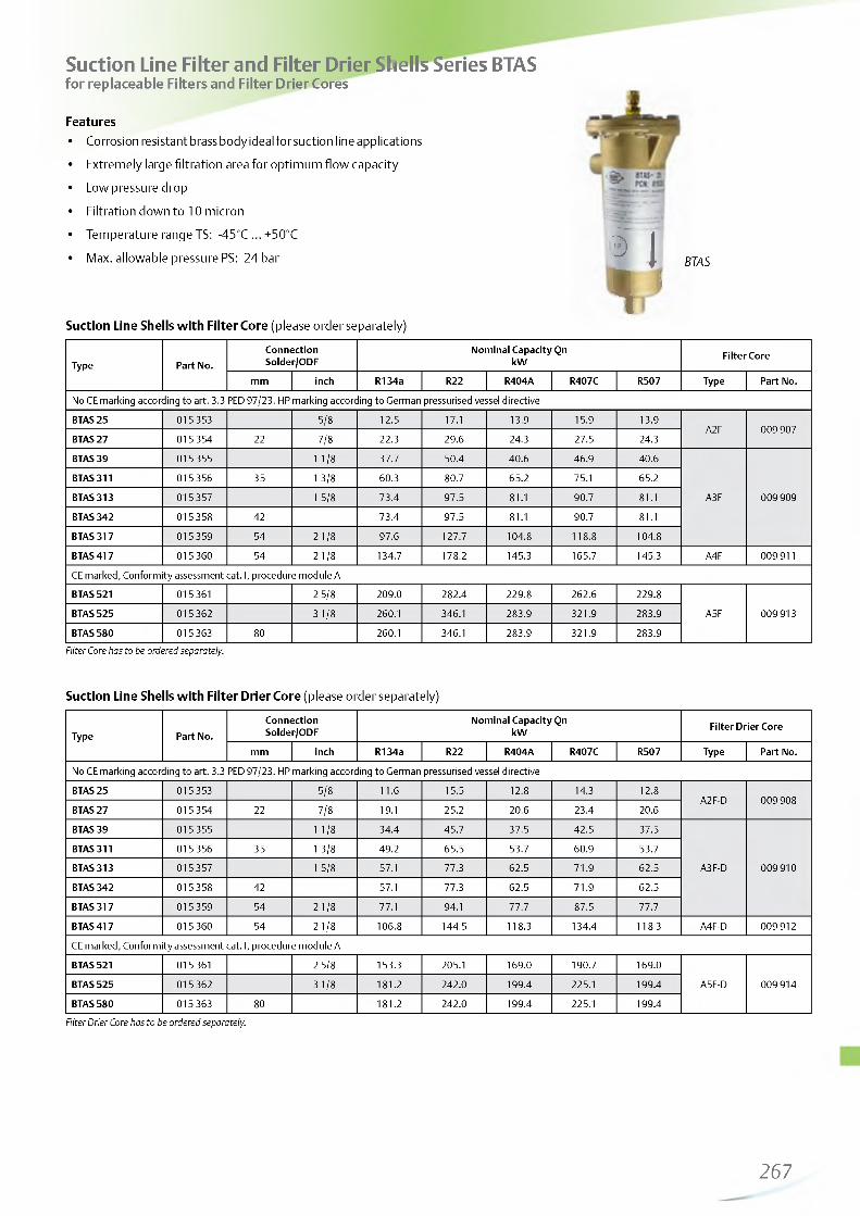
http://holodko.ru/
Suction Line Filter and Filter Drier Shells Series BTASfor replaceable Filters and Filter Drier Cores
FeaturesCorrosion resistant brass body ideal for suction line applications
Extremely large filtration area for optimum flow capacity
Low pressure drop
Filtration down to 10 micron
Temperature range TS: -45°C ... +50°C
Max. allowable pressure PS: 24 bar
Suction Line Shells with Filter Core (please order separately)
ItV
BTAS
Type Part No.ConnectionSolder/ODF
Nominal Capacity Qn kW Filter Core
mm inch R134a R22 R404A R407C R507 Type Part No.
No CE marking according to art. 3.3 PED 97/23. HP marking according to German pressurised vessel directive
BTAS 25 015353 5/8 12.5 17.1 13.9 15.9 13.9A2F 009 907
BTAS 27 015354 22 7/8 22.3 29.6 24.3 27.5 24.3
BTAS 39 015355 1 1 /8 37.7 50.4 40.6 46.9 40.6
A3F 009 909
BTAS 311 015356 35 1 3/8 60.3 80.7 65.2 75.1 65.2
BTAS 313 015 357 1 5/8 73.4 97.5 81.1 90.7 81.1
BTAS 342 015 358 42 73.4 97.5 81.1 90.7 81.1
BTAS 317 015 359 54 2 1 /8 97.6 127.7 104.8 118.8 104.8
BTAS 417 015 360 54 2 1 /8 134.7 178.2 145.3 165.7 145.3 A4F 009 911
CE marked, Conformity assessment cat. I, procedure module A
BTAS 521 015 361 2 5/8 209.0 282.4 229.8 262.6 229.8
A5F 009 913BTAS 525 015 3623 1/8 260.1 346.1 283.9 321.9 283.9
BTAS 580 015 363 80 260.1 346.1 283.9 321.9 283.9Filter Core has to be ordered separately.
Suction Line Shells with Filter Drier Core (please order separately)
Type Part No.ConnectionSolder/ODF
Nominal Capacity Qn kW Filter Drier Core
mm inch R134a R22 R404A R407C R507 Type Part No.
No CE marking according to art. 3.3 PED 97/23. HP marking according to German pressurised vessel directive
BTAS 25 015353 5/8 1 1 .6 15.5 12 .8 14.3 12 .8A2F-D 009 908
BTAS 27 015354 22 7/8 19.1 25.2 20.6 23.4 20.6
BTAS 39 015355 1 1 /8 34.4 45.7 37.5 42.5 37.5
A3F-D 009 910
BTAS 311 015356 35 1 3/8 49.2 65.5 53.7 60.9 53.7
BTAS 313 015 357 1 5/8 57.1 77.3 62.5 71.9 62.5
BTAS 342 015 358 42 57.1 77.3 62.5 71.9 62.5
BTAS 317 015 359 54 2 1 /8 77.1 94.1 77.7 87.5 77.7
BTAS 417 015 360 54 2 1 /8 106.8 144.5 118.3 134.4 118.3 A4F-D 009 912
CE marked, Conformity assessment cat. I, procedure module A
BTAS 521 015 361 2 5/8 153.3 205.1 169.0 190.7 169.0
A5F-D 009 914BTAS 525 015 3623 1/8 181.2 242.0 199.4 225.1 199.4
BTAS 580 015 363 80 181.2 242.0 199.4 225.1 199.4
Filter Drier Core has to be ordered separately.
267

http://holodko.ru/
Nominal capacity at +4°C evaporating temperature (saturated condition/ Qn: Nominal capacitydew point) and a pressure drop of 0.21 bar between inlet and outlet of Ks: Correction factor for a pressure drop corresponding 1K saturationBTAS. Correction factor for other evaporating temperatures than +4°C: temperature
Q = Q x K Q : Required cooling capacity
Evaporating Temperature (°C) +4 0 -5 -10 -15 -20 -25 -30 -35 -40Correction Factor kt 1.00 1.12 1.35 1.75 2.00 2.50 3.00 3.75 5.00 6.60
BTAS - Water and Acid Adsorption Capacity
Core
Water Adsorption Capacity (gram)Acid
Adsorption capacity (g)
Liquid Temperature 24°C Liquid Temperature 52°C
R134a R22 R404AR507 R407C R134a R22 R404A
R507 R407C
A2F-D 2.8 2.5 2.9 4.8 2.3 1.9 2.3 5.0 3.7A3F-D 7.6 6.8 8.0 13.3 6.3 5.3 6.2 13.8 10.3A4F-D 14.8 13.3 15.7 25.9 12.2 10.3 12.2 26.9 20.1
A5F-D 21.8 19.6 23.1 38.2 18.0 15.1 17.9 39.7 29.6
Spare parts
Repair Kits with cover, screws and gaskets Type Part No.Repair kit BTAS 2 KD 30519-2 065 970Repair kit BTAS 3 KD 30519-3 065 971Repair kit BTAS 4 KD 30519-4 065 972Repair kit BTAS 5 KD 30519-5 065 973
268—

http://holodko.ru/
Moisture Liquid Indicators Series MIAFeatures• Fully hermetic• Corrosion free stainless steel body• Crystal indicator element for long lifetime and reliability• Indication of dryness according to ASERCOM recommendation• Easy determination of moisture content• Sensitive indicator with calibrated four colours• Large clear viewing area• Lightweight (only 60g MIA-M06/014)• ODF extended tube configurations suitable for all commercial
applications• For R22, R407C, R134a, R404A, R507 and R410A together
with Mineral- and POE oils• Max. allowable pressure PS: 45 bar• UL certified for Canada, see SA 4876 (except MIA-078)
Selection ChartType Part No. for Tube Outside 0 Height A (mm) Lenght B (mm) Weight (g)
MIA 014 805 883 1/4” 25.7 98.0 60
MIA 038 805 884 3/8” 28.5 109.0 70
MIA 012 805 885 1 /2 ” 31.8 113.0 75
MIA 058 / MIA M16 805 886 5/8” / 16mm 31.8 108.5 85
MIA 078 805 887 7/8” 37.8 122.5 150
MIA 118 805 892 1 1 /8” 43.5 122.5 190
MIA M06 805 880 6 mm 25.9 98.0 60
MIA M10 805 881 10 mm 28.5 109.0 70
MIA M12 805 882 1 2 mm 28.5 113.0 75
MIA M28 805 891 28 mm 43.5 122.5 190
MIA M10 S Female/Male 805 888 10 mm 28.7 119.0 75
MIA M12 S Female/Male 805 889 1 2 mm 28.5 113.0 75
269

http://holodko.ru/
Water Contents* by Indicator Color
Refrigerant Liquid Temperature °C blue: dry purple fushia: Caution rose: Caution - wet
R2225 25 40 80 145
38 35 65 130 105
52 50 90 185 290
R404/R50725 15 33 60 12 0
38 25 50 1 1 0 150
52 45 60 140 180
R134a25 20 35 90 130
38 35 55 1 2 0 160
52 50 85 150 190
R407C25 26 42 94 151
38 40 68 144 232
52 64 109 230 371
R410A25 30 50 1 1 0 165
38 55 85 190 290
52 75 12 0 270 420
R744
-40 3 5 10 16
-2 0 6 10 20 32
-1 0 8 14 29 46
0 1 1 19 39 63
5 13 22 46 75
20 20 34 72 116
* Water content in mg Water per kg refrigerant (ppm)
270

http://holodko.ru/
Moisture Liquid Indicators Series AMI
Features
First choice for R134a, R22, R404A, R407C, R507 and polyolester lubricantsHigh accuracy of moisture indication according to ASERCOM recommendationFused glass - no leakageLong lifetime of indicators by utilization of crystals Indicator with high resistance against acid and water Wide angle view for exact distinction of vapour and liquid Max. allowable pressure PS: 31 bar
AMI-3Selection Chart
Part No.Connection
ConfigurationTypemm inch
SS 2 MM 805 732 6SS 2 805713 1/4SS 3 MM 805 733 10SS 3 805714 3/8SS 4 MM 805 734 12 Female solder x female solderSS 4 805715 1/2 ODFxODF
SS 5 805716 16 5/8SS 7 805717 22 7/8SS 9 MM 805 703 28SS 9 805 705 1 1/8TT 2 MM 805 697 6TT 2 805 655 1/4TT 3 MM 805 698 10
AMI-1 TT 3 805 654 3/8TT 4 MM 805 699 12 Female solder x female solder
ODFxODF (with extended copper tubes)TT 4 805 653 1/2
TT 5 805 652 16 5/8TT 7 805 656 22 7/8TT 9 MM 805 700 28TT 9 805 651 1 1/8MM 2 805 706 6 1/4MM 3 805 707 10 3/8
Male flare x male flareMM 4 805 708 12 1/2MM 5 805 709 16 5/8FM 2 805710 6 1/4FM 3 805 711 10 3/8 Female flare x male flareFM 4 805712 12 1/2S 11 805 704 35 1 3/8 Male solder
AMI-2 S 13 805 659 42 1 5/8 ODM
S 17 805 687 54 2 1/8 (for soldering into fitttings)
S 7 805 650 22 7/8Saddle type
(for soldering onto the pipe)AMI-3 S 9 805 649 28 1 1/8S 11 805 648 35 1 3/8
271

http://holodko.ru/
Water Contents* by Indicator Color
RefrigerantLiquid
Temperature°C
blue:dry purple fushia:
Cautionrose:
Caution - wet
25 25 40 80 145R22 38 35 65 130 205
52 50 90 185 29025 15 33 60 120
R404/R507 38 25 50 110 150
52 45 60 140 18025 20 35 90 130
R134a 38 35 55 120 16052 50 85 150 19025 26 42 94 151
R407C 38 40 68 144 23252 64 109 230 371
* Water content in mg Water per kg refrigerant (ppm)
Accessories
Type Part No.Lens assembly kit X 12978-1 805 742
O-Ring x 99995 805 643
272

http://holodko.ru/
Oil Management Components

http://holodko.ru/
Oil Management Components
Technical InformationRefrigeration compressors are lubricated by refrigeration oil that circulates from the compressor crankcase or housing. As refrigerant gas is discharged by the compressor, it will leave a fine oil mist that will be circulated throughout the entire system.Small amounts of oil circulating through the system will not affect the system performance. Too much refrigeration oil circulating in the system will have adverse effects on the components in the system. Circulating oil reduces the ability of the system to effectively remove the heat. Condensers, evaporators and other heat exchangers loose efficiency when coated internally with an oil film.
Refrigeration oil not returning to the compressor causes improper lubrication and eventual compressor failure. At low temperature application, refrigeration oil thickness becomes difficult to move, causing oil to be trapped in the system.
Oil Separator FunctionRefrigerant gas leaving the compressor through the discharge line contains refrigeration oil in a vaporous mist. As this mixture enters the oil separator, the velocity is reduced to allow oil separation to begin.
The refrigerant gas and oil mixture enters the oil separator and passes through an inlet screen, causing the fine particles to combine. Larger oil particles are formed and drop to the bottom of the oil separator.
The refrigerant gas then passes through an outlet screen to remove residual oil particles. The oil gathers in the bottom of the oil separator until a float operated needle valve opens to allow the return of oil to the compressor. Oil returns quickly to the compressor, because of the higher pressure in the oil separator than in the compressor crankcase. When the oil level has lowered, the needle valve retracts to prevent refrigerant gas from returning back to the compressor. The refrigerant gas leaves through the outlet of the oil separator and goes to the condenser.
Oil Level Management System FunctionThis system provides oil level balancing as well as oil level monitoring including alarm and compressor shut-down functions. The oil level is measured inside the compressors crankcase. By operating an integrated solenoid valve, missing oil can be fed from the oil receiver or from the oil separator directly into the compressor sump. If the oil level drops to a dangerous level, the alarm contact changes into alarm state. The alarm contact may be used to shut down the compressor. The integrated electronics include delay times in order to avoid short-cycling and nuisance alarms.
This system applies to compressor pack applications with multiple parallel com pressor arrangem ents, but also to stand-alone compressor applications for compressors without differential oil pressure monitoring.
274—

http://holodko.ru/
Electronic Oil Level Management Systems OM3 / OM4 TraxOilWith Alarm Function and Compressor Shut Down
FeaturesOM4 series for CO2 and R410A, OM3 for HFC refrigerants IP65 rating due to molded housing and electrical connection with molded cable assemblies3 Zone Level Control by using precise Hall-sensor measurement, not prone to errors by foaming or light like optical sensors Self contained unit with oil level sensor and integral solenoid valve to manage oil level supplySPDT output contact for compressor shut down or alarming, rating 230 VAC/3A Supply 24VAC or 230VAC Alarm, status and 3 zone level indication by LEDs Easy installation by sightglass replacement and frontside installation without nuts Visual inspection of oil level still possible
OM4 with 24V supp ly OM4 with OM-230V
Adapters suitable for various types of compressors Recommended by leading compressor manufacturers
C€ marking under Low Voltage and EMC Directive
Product Selection (select one item of each group)
1 . Base U n its (supplied without adapter and coil)
Type Part No. Max. working pressure
Time delay alarm
OM3-020 80513335 bar
20 sec
OM3-120 805134 120 sec
OM4-020 805135 60 bar 20 sec
2 . A d a p te r fla n g e s
OM0-CUA 805037 Flange adapter 3- / 4-hole
OM0-CBB 805038 Screw adapter 1-1/8“-18 UNEF
OM0-CCA 805039 Screw adapter 3/4“-14 NPTF
OM0-CCB 805040 Screw adapter 1-1/8“-12 UNF
OM0-CCC 805041 Flange adapter 3-hole
OM0-CCD 805042 Rotalock adapter 1-3/4”-12UNF
OM0-CCE 805043 Rotalock adapter 1-1/4”-12UNF
3 . C ab le s A la rm R e lay
OM3-N30 805141 Connection to Relay 3.0m
OM3-N60 805142 Connection to Relay 6.0m
Supply vo ltage 24V Supply vo ltage 230V
4 . S o le n o id C o il 4 . S o le n o id Coil
Type Part No.
ASC 24 VAC 801062 50/60 Hz, 15 VA
Type Part No.
ASC 230 VAC 801064 50/60 Hz, 15 VA
5 . C ab le A s se m b ly P o w e r S u p p ly an d S o le n o id 5 . C ab le A s se m b ly P o w e r S u p p ly an d So le n o id
OM3-P30 805151 24V, 3.0m
OM3-P60 805152 24V, 6.0m
OM-230V-3 805161 230V, 3.0m
OM-230V-6 805162 230V, 6.0m
275

http://holodko.ru/
Adapter Selection Guideline
Compressor series with 0M3: Compressor series with 0M4:OM4 can be incorporated in compressors designed for CO2 transcritical in conjunction with oil receivers/reservoirs up to 60bar
Arctic Circle G2, G4, G6
Bitzer 4VC, 4TC, 4PC, 4NC, 4J, 4H, 4G, 6J,6H, 6G, 6F, 8GC, 8FC
4- VHC-10K, THC-12K, PHC-15K,NHC-20K, VSL-15K, TSL-20K, PSL-25K, NSL-30K
0M0-CUA PartNo. 805037 Bock HA, HG (except HG/HA-34/22, see-CBB), O-Series HGX4/310-4, 385-4, 464-4, 555-4Flange adapter 3- / 4-hole
Copeland 4M & 6M (except transcritical 4MTL models), D2, D3, D4, D6, D9,4CC, 6CC, ZBH
Dorin all KP, K sizes (except those mentioned under- CBB)
SCC 250/300/350/380/500/750/1500/1900/2000/2500/ -B, SCS 34 0/3 5 1 /3 6 2 /3 7 3 /3 8 5 /3 K8/-D
Frascold Series A, B, D, F, S, V, W, Z A-SK, D-SK, F-SK, Q-SK, S-SK
Bitzer 2KC, 2JC, 2HC, 2GC, 2FC, 2EC, 2DC, 2CC, 4FC, 4EC, 4DC, 4CC
2- KHC-05K/ JHC-07K/ HHC-2K/ GHC-2K/ FHC-3K/ EHC-3K/ DHC- 3K/ CHC-4K, MHC-05K, KSL-1K/ JSL-2K/ HSL-3K/ GSL-3K/ FSL-4K/ ESL-4K/ DSL-5K/ CSL-6K/ MSL-7K,4- CHC-9K/ DHC-7K/ EHC-6K/ FHC-5K MTC,KTC,JTC-10K & 15K, HTC-15K & 20K, FTC-20K & 30K
0M0-CBB PartNo. 805038 Screw adapter 1-1/8“-18 UNEF
Bock HA12/22/34, HG12/22/34HGX12P/40-4, 50-4, 60-4,75-4 HGX22P110-4, 125-4, 160-4, 190-4 HGX34P215-4, 255-4
Copeland 4MTL
Dorinall H, K100CC/CS, K150CC/CS, K180CC/CS, K200CC, K230CS, K235CC, K240SB, K40CC, K50CS, K75CC/CS-
L'Unite Herm. TAH, TAG
Maneurop LT, MT, SM, SZ
Bitzer ZL, ZM
0M0-CCA PartNo. 805039 Screw adapter 3/4“-14 NPTF Copeland
ZB 15 to ZB45ZB 56, 75, 92, 11 - until May 2012 ZF 06 to ZF11; ZF13 to ZF18 *ZF 24 to ZF 48 * - until May 2012 ZS 21 to ZS 45ZS 56 to ZS 11 - until May 2012
ZO34, ZO45, ZO58, ZO88, ZO104
0M0-CCB PartNo. 805040 Screw adapter 1-1/8“-12 UNF Copeland DK, DL
0M0-CCC Part No. 805041 Flange adapter 3-hole Copeland D8D, D8S_ (except D8SJ and D8SK, installation
only on one sight glass)
0M0-CCD PartNo. 805042 Rotalock adapter 1-3/4“-12 UNF
CopelandZB220, ZH, ZR 90, 11, 12, 16,19 ZR250 to ZR380,ZF 24 to ZF 48, ZS 56 to ZS 11
ZP 180, ZP 235 to ZP 485
0M0-CCE PartNo. 805043Copeland ZB50, 58, 66, 76, 95, 114,
ZR 94/108/125/144/160/190 ZP 90/103/120/137/154/182
Rotalock adapter 1-1/4”-12 UNFBitzer GSD60182 to 60235
GSD80182, 80235, 80295 to 80485
*) Digital or EVI variations o f standard models have the same sight glass/ will use the same adaptor as the standard model. Other adaptor types on request!
276

http://holodko.ru/
Oil Management Kits including adapter and 24V Coil: cross reference
Kit inc. Adapter Part No.
OM3-CUA 805030
OM3-CBB 805032
OM3-CCA 805033
OM3-CCB 805034
OM3-CCC 805035
OM3-CCD 805031
OM3-CCE 805029
O
Base Unit Part No. Adapter Part No. Coil Part No.
OMO-CUA 805037
OMO-CBB 805038
OMO-CCA 805039
OM3-020 805133 OMO-CCB 805040 ASC 24 VAC 801062
OMO-CCC 805041
OMO-CCD 805042
OMO-CCE 805043
OM4-CUA 805060
OM4-CBB 805062
OM4-CCA 805063
OM4-CCB 805064
OM4-CCC 805065
OM4-CCD 805061
OM4-CCE 805066
O
OMO-CUA 805037
OMO-CBB 805038
OMO-CCA 805039
OM4-O2O 805135 OMO-CCB 805040 ASC 24 VAC 801062
OMO-CCC 805041
OMO-CCD 805042
OMO-CCE 805043
AccessoriesECT-323 804 424 Transformer 23OVAC / 24VAC, 25VA (supply of 1 pc. OM3/OM4)
ECT-623 804 421 Transformer 23OVAC / 24VAC, 6OVA (supply of 3 pcs. OM3/OM4)
ODP-33A 800 366 Differential oil check valve 3.5 bar, inlet 15/16 -18UNF female, outlet 5/8 -18UNF male, PS 35 bar, OM3 only
Technical Data
Supply voltage / total power OM3/4 with 24VAC ASC coil. 24VAC, 5O/6OHz, + 1O/-15%, 17A
OM3/4 with OM-23OV-x module. 23OVAC, 5O/6O Hz, 17VA
Maximum allowable pressure PS OM3: 35 bar, OM4: 6O bar
Solenoid valve MOPD OM3: 21 bar, OM4: 3O bar
Medium temperature -20 to 80°C
Ambient/Storage Temperature -20 to 50°C
Time delay filling Time delay alarm
10 s2O s, OM3-12O: 12O s
Body material Aluminum
Screw material Stainless Steel
Medium compatibility HCFC, HFC, CO2,mineral, synthetic, and ester lubricants
Orientation of base unit horizontal
Level Control 4O to 6O% of sightglass height
Protection class IP 65 (IEC529/EN 60529)
Weight 850 ... 930g (dep. on adapter)
Alarm contact max. 3A, 23OVAC, SPDT dry contact
ApplicationTraditional low pressure oil level management system High pressure oil level management system
(D
i i i i
12
345678
*
Differential pressure valveOil reservoirCondenserFilter DrierCom m on DischargeCom m on Suction Normal TempSuction Line Low TempOil Separator
w iff f r
1111
©\ /
Com m on Suction Com m on Discharge Condenser Filter Drier Oil Separator
_ r ® i ,-11X11I I 1 *
---------L II II If
277

http://holodko.ru/
Electronic Oil Level Monitoring TraxOil OW4 Oi
The TraxOil OW4 is a self-contained system which provides oillevel monitoring and alarm functionality, protecting especiallycompressors having no oil pump.
Features• Suitable for HFCs, R410A and CO2• IP65 rating due to molded housing and new electrical
connection with molded cable Assemblies• 3 Zone Level Control by using precise Hall-sensor measure
ment, not prone to errors by foaming or light like optical sensors
• CE marking under Low Voltage and EMC Directive• SPDT output contact for compressor shut down or
alarming, rating 230VAC / 3A• Easy installation by sight-glass replacement and front side
mounting without nuts• Self contained unit with oil level sensor• Alarm, status and 3 zone indication by LED's• Supply 24V AC, 50/60Hz
Selection (select one item of each group)1. Base Unit (supplied without adapter)
Type Part No. Max. working pressure Time delay alarm
OW4-020 805116 60 bar 20 sec
2. Power CableType Part No. Description Cable length
OW-24V-3 804672 Connection to Power Supply 24VAC 3,0m
3. Relay CablesOM3-N30 805141
Connection to Relay3,0m
OM3-N60 805142 6,0m
4. Adapter flangesOM0-CUA 805037 Flange adapter 3-/4-hole
OM0-CBB 805038 Screw adapter 1-1/8“-18 UNEF
OM0-CCA 805039 Screw adapter 3/4“-14 NPTF
OM0-CCB 805040 Screw adapter 1-1/8“-12 UNF
OM0-CCC 805041 Flange adapter 3-hole
OM0-CCD 805042 Rotalock adapter 1-3/4”-12UNF
OM0-CCE 805043 Rotalock adapter 1-1/4”-12UNFCompressor models see OM3 series.
Technical Data
Max. working pressure PS 60 bar
Supply voltage / current 24VAC, 50/60Hz, + 10/-15%, 0.05A
Vibration resistance (EN60068-2-6) max. 4g, 10....250Hz
Medium temperature -20 to 80°CAmbient/Storage temperature -20 to 50°C
Medium compatibility HCFC, HFC, CO2, mineral, synthetic and Ester lubricants
Materials:Body and AdaptorScrewsSight Glass
aluminum (EN AW 6060) stainless steel (ISO 4762) nickel-plated steel (1.05.03 DIN EN 10027)
Orientation of base unit: Level control
horizontal, +/- 1°40% to 60% sight glass height
Alarm contact: max. 3A, 230VAC SPDT dry contact
Time Delay Alarm: 20 sec
Protection class IP 65 (IEC529/EN 60529)
Weight 850 ... 920g incl. adapter
278

http://holodko.ru/
Oil Separator Series OS
Features• Three different construction styles:
- Hermetic- Top flange- Bottom flange with support bracketStainless steel needle valve and floaterPermanent magnet to catch iron particles out of the systemCorrosion resistant epoxy powder painting ODF Copper fittings for easy soldering Temperature range TS: -10°C ... +150°C Max. allowable pressure PS: 31 bar CE marking according PED 97/23 EC
OSH OST
Type CodeOS X -X XX
Product line Oil Separators Construction
H: Hermetic T: Top flangeB: Bottom flange with supporter
Nominal shell diameter --------4: approx. 10 cm 6: approx. 15 cm
ODF connection04: V05: V (16mm)07: 7/8“ (22mm)09: 11/8*11: ‘ (35mm)13: 15/8‘17: 27 8°
OSB
Type Part No. ConnectionConformityAssessment
Category
ConformityAssessmentProcedure
Nominal capacity (kW)Volume
Lit.R22/R407C R134A R404A/ R507
OSH-404 881 598 1/2”
Cat. I Module D1*
7.0 4.9 7.3 2.0OSH-405 881 599 5/8” 18.7 13.1 19.4 2.4OSH-407 881 600 7/8” 28.1 19.7 29.0 2.8OSH-409 881 792 1 1/8” 37.4 26.2 38.7 3.0OSH-411 881 794 1 3/8” 46.8 32.8 48.4 3.6
OSH-413 881 856 1 5/8” 65.5 45.9 67.8 3.6OSH-611 881 940 1 3/8”
Cat. II Module D1
51.5 36.1 53.3 6.5OSH-613 881 953 1 5/8” 65.5 45.9 67.8 7.9OSH-642 889 022 42 mm 65.5 45.9 67.8 7.9OSH-617 881 970 2 1/8” 105.3 73.8 108.9 7.9OST-404 881 860 1/2”
Cat. I Module D1*
7.0 4.9 7.3 1.8OST-405 881 861 5/8” 18.7 13.1 19.4 2.6
OST-407 881 862 7/8” 28.1 19.7 29.0 3.2OST-409 881 863 1 1/8” 37.4 26.2 38.7 3.8OST-411 881 938 1 3/8” 46.8 32.8 48.4 3.8OST-413 881 939 1 5/8” 65.5 45.9 67.8 3.8OSB-613 881 971 1 5/8”
Cat. II Module D165.5 45.9 67.8 7.8
OSB-617 881 972 2 1/8” 105.3 73.8 108.9 7.8* applied higher module as required
279

http://holodko.ru/
Capacity Data For Other Than Nominal Operating ConditionsNominal capacities at +38°C condensing temperature (+38°C bubble point or +43°C dew point for R407C), +4°C evaporating temperature (saturated temperatures / dew point) and 1 K liquid subcooling at the inlet of the expansion valve.
Correction factor for other evaporating tem peratures than nominal:
Q = Q x K
Qn: Nominal capacityKt: Correction factor for a pressure drop corresponding 1 K
saturation temperature Qo: Required cooling capacity
Correction Factors
Refrigerant Condensing Temperature °C
Correction factor Kt Evaporating Temperature °C
10 0 -10 -20 -30 -40 -50
R22R407
25 1.29 1.31 1.33 1.36 1.40 1.44 1.4930 1.16 1.17 1.20 1.23 1.27 1.31 1.3635 1.05 1.07 1.09 1.11 1.13 1.17 1.2340 0.95 0.96 0.98 1.00 1.03 1.07 1.1245 0.87 0.88 0.90 0.92 0.95 0.99 1.04
50 0.81 0.83 0.85 0.87 0.89 0.93 0.99
Refrigerant Condensing Temperature °C
Correction factor Kt Evaporating Temperature °C
10 0 -10 -20 -30
R134a
25 1.31 1.36 1.39 1.43 1.5030 1.18 1.21 1.24 1.28 1.3535 1.06 1.08 1.11 1.15 1.2140 0.95 0.98 1.01 1.05 1.1045 0.86 0.88 0.92 0.95 1.0250 0.80 0.81 0.85 0.89 0.97
Refrigerant Condensing Temperature °C
Correction factor Kt Evaporating Temperature °C
10 0 -10 -20 -30 -40 -50
R404AR507
25 1.22 1.25 1.30 1.33 1.43 1.53 1.6330 1.12 1.15 1.20 1.26 1.32 1.42 1.54
35 1.03 1.06 1.11 1.16 1.24 1.34 1.4640 0.95 0.99 1.04 1.09 1.17 1.28 1.4145 0.90 0.92 0.97 1.03 1.14 1.26 1.3950 0.86 0.89 0.93 1.00 1.13 1.26 1.39
280

http://holodko.ru/
Suction Accumulators, Ball Valves and Oil Test Kit

http://holodko.ru/
Suction Accumulators
Features• Hermetic design• ODF Copper fittings for easy soldering• Corrosion resistant epoxy powder painting• Internal orifice with strainer for optimum oil return• Temperature range TS: -45°C to +65°C• Max. allowable pressure PS:
20.7 bar (-10°C to +65°C)15.5 bar (-45°C to -10°C)
• CE marking for certain types according PED 97/23 EC• HP marking for certain types according German pressurised
vessels directive A08
Connec Nominal Capacity Qn (KW) ConformityVolume
Lit.Type Part No. tion R22/R407 R134a R404A R507 Assessment“(inch) Max. Min. Max. Min. Max. Min. Category procedure
A08-304 001 973 1/2 7.0 1.1 4.2 0.6 4.6 0.7 0.73
A10-305 001 977 5/8 10.5 1.6 6.0 0.9 7.0 1.1 0.93A12-305 001 978 5/8 10.5 1.6 6.0 0.9 7.0 1.1 1.16A12-306 001 979 3/4 14.0 2.1 8.1 1.2 9.1 1.4 HP Marking
(CE Marking1.16
A14-305 001 980 5/8 10.5 1.6 6.0 0.9 7.0 1.1 1.40A14-306 001 987 3/4 14.0 2.1 8.1 1.2 9.1 1.4 not required) 1.40A06-405 001 989 5/8 10.5 1.6 6.0 0.9 7.0 1.1 0.93A10-405 001 990 5/8 10.5 1.6 6.0 0.9 7.0 1.1 1.75A10-406 001 994 3/4 14.0 2.1 8.1 1.2 9.1 1.4 1.75
A09-506 881 995 3/4 14.0 2.1 8.1 1.2 9.1 1.4 2.33A09-507 882 455 7/8 25.6 3.8 14.0 2.1 16.1 2.4 2.33A12-506 881 996 3/4 14.0 2.1 8.1 1.2 9.1 1.4 3.29A12-507 881 998 7/8 25.6 3.8 14.0 2.1 16.1 2.4 3.29A13-507 882 007 7/8 25.6 3.8 14.0 2.1 16.1 2.4 3.80A13-509 882 011 1 1/8 41.4 6.2 25.3 3.8 26.7 4.0 3.80A17-509 882 012 1 1 /8 41.4 6.2 25.3 3.8 26.7 4.0 4.87
A17-511 882 013 1 3/8 66.0 9.9 37.6 5.6 42.8 6.4 Cat. I Mod. D1* 4.87A11-607 882 014 7/8 25.6 3.8 14.0 2.1 16.1 2.4 4.30A13-607 882 015 7/8 25.6 3.8 14.0 2.1 16.1 2.4 4.98A13-609 882 019 1 1/8 41.4 6.2 25.3 3.8 26.7 4.0 4.98A14-611 882 020 1 3/8 66.0 9.9 37.6 5.6 42.8 6.4 5.48A17-613 882 022 1 5/8 100.0 15.0 59.7 9.0 63.9 9.6 6.85A17-642 889 023 42 mm 100.0 15.0 59.7 9.0 63.9 9.6 6.85A20-613 882 021 1 5/8 100.0 15.0 59.7 9.0 63.9 9.6 8.21
A25-613 882 023 1 5/8 100.0 15.0 59.7 9.0 63.9 9.6 Cat II Mod. D1* 10.23
* applied higher module as required
Correction facto r fo r other evaporating tem peratures than nom inal:
Qn = Qo X K
Q n : Nom inal capacity Kt : Correction facto r fo r a pressure drop
corresponding 1 K saturation tem perature Q : Required cooling capacity
Evaporating Temperature (°C) +4 0 -5 -10 -15 -20 -25 -30 -35 -40
Correction Factor Kt 1.00 1.12 1.35 1.75 2.00 2.50 3.00 3.75 5.00 6.60
282

http://holodko.ru/
Ball Valves Series BVE / BVS
Features• BVS version with schrader valve• Two threads at valve body for easy mounting• Hermetic design• Max. allowable pressure PS: 45 bar• Compatible for high pressure refrigerants as R410A and CO2
(sub-critical)• Light weight design• Virgin PTFE seat gaskets• Bi-directional flow characteristics• Valve cap retained by strap attached to main body• Pressure relief port design• UL approval and CE marking acc. PED 97/23 EC• Applied Standards EN 12284, EN 378, EN12420, PED 97/23/EC
RoHS 2002/95/EC• To protect valve from un-authorized use a special cap is
available as accessory (see below)
TypeBVE Part No. Type
BVS Part No.Connection size ODFinch metric
BVE-014 806 730 BVS-014 806 750 1/4”
BVE-M06 806 731 BVS-M06 806 751 6mmBVE-038 806 732 BVS-038 806 752 3/8”BVE-M10 806 733 BVS-M10 806 753 10mmBVE-012 806 734 BVS-012 806 754 1/2”BVE-M12 806 735 BVS-M12 806 755 12mmBVE-058 806 736 BVS-058 806 756 5/8” 16mmBVE-034 806 737 BVS-034 806 757 3/
BVE-078 806 738 BVS-078 806 758 7/8” 22mm
BVE-118 806 739 BVS-118 806 759 1 1/8”BVE-M28 806 740 BVS-M28 806 760 28mmBVE-138 806 741 BVS-138 806 761 1 3/8” 35mmBVE-158 806 742 BVS-158 806 762 1 5/8”BVE-M42 806 743 BVS-M42 806 763 42mmBVE-218 806 744 BVS-218 806 764 2 1/8” 54mmBVE-258 806 745 BVS-258 806 765 2 5/8”
BVE-318 806746 BVS-318 806766 3 1/8”
Technical Data
Max. allowable pressure PS 45 barTest pressure PT 49.5 barMedium temperature TS -40 ... 120°C (150°C short term)
Medium compatibility HFC, HCFC, CO2, Mineral, Synthetic and Polyol-Ester (POE) lubricants
Special Seal Caps to protect valve from unauthorized use
BVE / BVS Valve Size Part No. Thread (3) Quantity per pack
1/4” ... 7/8” (6 ... 22mm) 806 770 M18x1 10 pcs1-1/8” ... 1 3/8” (28 ... 35mm) 806771 M27x1 10 pcs1-5/8 (42 mm) ... 2-5/8” 806 772 M36x1 10 pcs
283

http://holodko.ru/
Acid Test Kid Series AOKFeatures• Quick & easy test kit• Universal acid test kit for use with all oils:
Mineral, POE, etc.• By changing the percentage of oil sample taken, the acid
number of the oil can be accurately determined• Phase separation of the chemicals in the kit provide a positive
colour change regardless of the colour and condition of the oil
Type Part No.AOK-UQ1 804166
AOK
284

http://holodko.ru/
Accessories & Spare Parts

http://holodko.ru/
Controller Kits Parts List
5 alcE£
K03-
X32
K03-
X33
K09-
U00 00o
CN0K K02-
211
K02-
540
K03-
110
K03-
331 041.0
rn0K
05r-̂rn0K
Sens
ors EC
N-F6
0
ECN-
H60
ECN-
N60
ECN-
S60
er
mrroMsnar£
32m 1—CE
32Ln 1—CE EC
T-62
3
Pres
sure
Tra
nsm
itter
s
7oi_nPT5 PT
5-18
M M0mi_nPT5
Cable
Ass
embl
y PT
5
PT4-
M60
Controller Kit PCN807
64
4
807
645
804
559
800
050
807
647
800
070
807
656
807
648
807
653
807
654
804
283
804
359
804
497
804
284
804
424
804
332
804
421
802
350
802
351
802
352
804
805
Superheat
EC3-D72 Ctr. Kit TCP/IP 808 042 1 1 1 1 1
EC3-D72 Ctr. Kit TCP/IP, R410A 808 049 1 1 1 1 1
EC3-D73 Ctr. Kit 808 041 1 1 1 1 1
EC3-X32 Ctr. Kit TCP/IP 808 037 1 1 1 1 1
EC3-X33 Ctr. Kit 808 036 1 1 1 1 1
EXD-U00 Ctr. Kit 808 038 1
Display Case
EC2-211 Ctr. Kit LON 808 000 1 1 2 1
EC2-212 Ctr. Kit TCP/IP 808 001 1 1 2 1
EC2-291 Ctr. Kit LON 808 002 1 1 2 1
EC2-292 Ctr. Kit TCP/IP 808 003 1 1 2 1
EC2-312 Ctr. Kit TCP/IP 808 005 1 1 2 2 1
EC2-351 Ctr. Kit LON 808 008 1 1 1 2 1 1 1
EC2-352 Ctr. Kit TCP/IP 808 009 1 1 1 2 1 1 1
EC2-371 Ctr. Kit LON 808010 1 1 3 1 1 1
EC2-372 Ctr. Kit TCP/IP 808011 1 1 3 1 1 1
EC2-391 Ctr. Kit LON 808 006 1 1 4 1
EC2-392 Ctr. Kit TCP/IP 808 007 1 1 4 1
Cond. Unit & Condenser
EC2-512 Ctr. Kit TCP/IP 808 015 1 1 1 1 2
EC2-552 Ctr. Kit TCP/IP 808 019 1 1 1 1 2
EC2-741 Ctr. Kit LON 808 022 1 1 1 1
EC2-742 Ctr. Kit TCP/IP 808 023 1 1 1 1
Cold Room
EC3-331 Ctr. Kit LON 808 012 1 1 1 1 1 1 1
EC3-332 Ctr. Kit TCP/IP 808 013 1 1 1 1 1 1 1
Rack & Condenser
EC3-652 Ctr. Kit TCP/IP 808 046 1 1 1 1 1 2
EC3-672 Ctr. Kit TCP/IP 808 029 1 1 1 1 2
EC3-752 Ctr. Kit TCP/IP 808 031 1 1 1 1
EC3-812 Ctr. Kit TCP/IP 808 033 1 3 1 1 1
EC3-932 Ctr. Kit TCP/IP 808 044 1 4 1 1 1 1 2
286

http://holodko.ru/
Accessories, Spare Parts & AppendixElectronic controllers
Description Type Part No.
EC3 R ep lacem en t b a tte ry 807790
Thermo - Expansion ValvesBulb c lam p X B 1 0 1 9 XA 1728-4 803 260
Bulb c lam p X C 7 2 6 XA 1728-5 803261
Serv ice Tool fo r T Series X 99999 800 005
G asket sets fo r T , Z Z , L, 9 3 5 and TG Series va lves X 13455-1 027 579
Bro nze S crew s fo r fo llo w ing fl ang e typ es : (ZZ-Valves) C 5 0 0 , C 5 0 1 , 9 7 6 1 , X 6 3 4 6 , X 6 6 6 9 , A 5 7 6 Screw BZ 32 803 5759 1 4 8 , 9 1 4 9 , 9 1 5 2 , 9 1 5 3 , 1 0 3 3 1 , 1 0332 Screw BZ 48 803 576
Steel S crew s fo r fo llo w in g fl ang e typ es : C 5 0 0 , C 5 0 1 , 9 7 6 1 , X 6 3 4 6 , X 6 6 6 9 , A 5 7 6 Screw ST 32 803 5739 1 4 8 , 9 1 4 9 , 9 1 5 2 , 9 1 5 3 , 1 0 3 3 1 , 1 0332 Screw ST 48 803 574
Solenoid Valves
Coil clip 801 295
Serv ice too l fo r 1 1 0 R B , 2 4 0 R A , 5 4 0 R A , M 36 X 11981-1 027 451
Plug a cc . To DIN 4365O cab le g land PG9 GDM 2009 / PG9 801 012
Plug a cc . To DIN 4365O cab le g land PG11 GDM 211 / PG11 801 013
110 RB KS 30040-1 801 206
2 00 RB KS 30039/
KS30109 801 205
2 40R A B KS 30061 801 262
Repair k its: 240R A 9 KS 30062 802 263
2 4 0 R A 1 2 KS 30063 803 264
2 4 0 R A 1 6 KS 30065 801 200
2 4 0 R A 2 0 KS30097 801 216
M 36-O78 / M 36 -1 18 / 3O31 (u p p e r a ssem b ly inc. G asket) M36-UNF 801 440
110 RB KS 30040-2 801 232
2 00 RB KS 30039-1 802 233
24 0 R A B KS 30061-1 803 234
G asket k its: 2 4 0 R A 9 /1 2 KS 30062-1 804 235
2 4 0 R A 1 6 KS 30065-1 805 236
2 4 0 R A 2 0 KS 30097-1 806 237
all 3031 KS 30177-1 807 268
Pressure ControlsM ounting b rac ke t, an g le , in clud ing sc rew s U n ive rsa l fo r P S1 , P S2 , FD 113
803 799
M ounting b racke t un ive rsa l 803 798
Extensio n b racke t fo r P S1 , PS2 803 800
M ounting p late fo r u n its w ith hood 803801
Plug a cc . To DIN 4 3 6 5 0 fo r PS3C ab le g land PG9 801 012
C ab le g land PG11 801 013
C a p illa ry tu b e w ith fl a re nuts 7 /1 6 ” - 20U N F, 1 /4 ” SA E , 1 .5 m 803804
C opper g aske t se t (1 0 0 pcs) fo r R 1 /4 ” (7 /1 6 ” - 20U N F, fem a le ) 803 780
ThermostatsM ounting b racke t ang le 803 799
U nive rsa l m o un tin g b racke t 803 798
Extensio n b racke t fo r TS1 703 800
Insu la tio n co nso le TS1 stand ard 803 777
C a p illa ry tu b e g lan ds R “ th re ad , fo r bu lb s ty le A /C 803 807
C a p illa ry tu b e ho lder (5 pcs) 803 778
C a p illa ry tu b e w ith fl a re nuts 7 /1 6 ” - 20U N F, 1 /4 ” SA E , 1 .5m 803804
287

http://holodko.ru/
Oil Management
O M 3 / OM 4 Flan ge ad ap te r 3-/4-ho le OM0-CUA 805 037
S c re w ad ap te r 1 1 /8 ” - 18U N EF OM0-CBB 805 038
S c re w ad ap te r 3 /4 ” - 14N PTF OM0-CCA 805 039
S c re w ad ap te r 1 1 /8 ” - 12U N F OM0-CCB 805 040
Flan ge ad ap te r 3-ho le OM0-CCC 805 041
R o ta lo ck ad apte r 1 -3 /4 ” - 12U N F OM0-CCD 805 042
R o ta lo ck ad apte r 1 -1 /4 ” - 12U N F OM0-CCE 805 043
Flan ge ad ap te r 4 -ho le OM0-CCF 805 044
Tra n sfo rm er 2 30 V A C / 24V A C , 25V A ECT-323 804 424
Tra n sfo rm er 2 30 V A C / 24V A C , 60V A ECT-623 804 421
D ifferen tia l o il ch e c k va lve 3 .5 bar, PS: 35 bar (in le t 5 /8 ” - UN F fe m a le , o u tle t 5 /8 ” - UNF m ale )
ODP-33A 800 366
Repa ir k it fo r all O M 3/O M 4 typ es(all n ecessa ry g aske ts , co il c lip and ol ad ap te r w ith sc reen )
OM3-K01 805 036
OS G asket se t fo r O SB / O ST (5 0 pcs) X 99956 007 591
Description Type Part No.
Filter DriersA ll A D K S , A D K S-P lu s
G aske t set X 99961 003 710
Sch rad e r n ipp le 1 /4 ” N PT X 11562-2 803 251
C o re h o lder X 99963 003 712
FDS 48
O 'R ing set X 99962 003 711
FDS 24
G asket set X 99967 003 716
O 'R ing set X 99968 003 717
C o re h o lder X 99969 003 718
BTAS Rep a ir k its w ith sc re w s , g aske ts , spring and b rass cover:
BTAS 2 KD 30519-2 065 970
BTAS 3 KD 30519-3 065 971
BTAS 4 KD 30519-4 065 972
BTAS 5 KD 30519-5 065 973
IndicatorsAM I upp er p a rt w ith in d ica to r X 12978-1 805 742
O 'R in g s 20 pcs X 99995 805 643
Ball ValvesBVE/BV S special cap to p ro tec t va lve fro m u n-au tho rized use (1 0 pcs)
1 /4 ” - 7 /8 ” (6 -2 2 m m ) 806 770
1 1 /8 ” - 1 3 /8 ” (2 8 -3 5 m m ) 806 771
1 5 /8 ” - 3 1 /8 ” (4 2 -5 4 m m ) 806 772
■//
288

http://holodko.ru/
Conversion Table
PowerkW / h = Kcal / h : 860 Kcal / h = kW / h x 860kW = US ton of refrigeration : 0,284 US ton of refrigeration = kW x 0,284kW = BTU / h : 3413 BTU / h = kW x 3413
Temperature°C = (°F - 32) : 1,8 °F = (°C x 1,8) + 32
Pressurebar = PSI : 14,5 PSI = bar x 14.51 bar = 100 000 Pascal 100 Pascal = 1 mbar
Connections
Connection TubeThread
SAE inch metricSAE 1/4” 1/4” 6mm 7/16” - 20UNF
SAE 5/16” 5/16” 8mm 5/8” - 18UNFSAE 3/8” 3/8” 10mm 5/8” - 18UNFSAE 1/2” 1/2” 12mm 3/4” - 16UNFSAE 5/8” 5/8” 16mm 7/8” - 14UNFSAE 3/4” 3/4” 18mm 1 1/16” - 14UNF
SAE FlareSAE 7/8” 7/8” 22mm 1 1/4” - 12UNFSAE 1” 1 25mm 1 1/2” - 12UNF
1 1/8”
1 3/8” 35mm1 5/8”2 1/8” 54mm2 5/8”3 1/8”
R or Gsame as
BSP
Pipe thread female
cylindricalMale thread: R / NPT / BSP / G
Withworth- Pipe thread
DIN 2999 / ISO 228R
same as BSP
Pipe thread male
taperingFemale thread: R / NPT / BSP / G
Withworth- Pipe thread DIN 2999
GPipe thread
malecylindar
Female thread: R / BSP / GWithworth- Pipe thread
ISO 228
NPT
Pipe thread femaletapering
Male thread: R / NPT / BSPStandard taper
Pipe thread ASA B 2.1Pipe thread
maletapering
Female thread: R / NPT / BSP / G
ODFOutside
DiameterFemale
Solderfemale
Given dimension is outside tube diameter. Tube has to be pushed into ODF connection.
ODMOutside
DiameterMale
Soldermale Expanded tube
Given dimension is outside tube diameter. can be pushed onto ODM connection or tube can be connected through a
sleeve with the ODM connection.
289
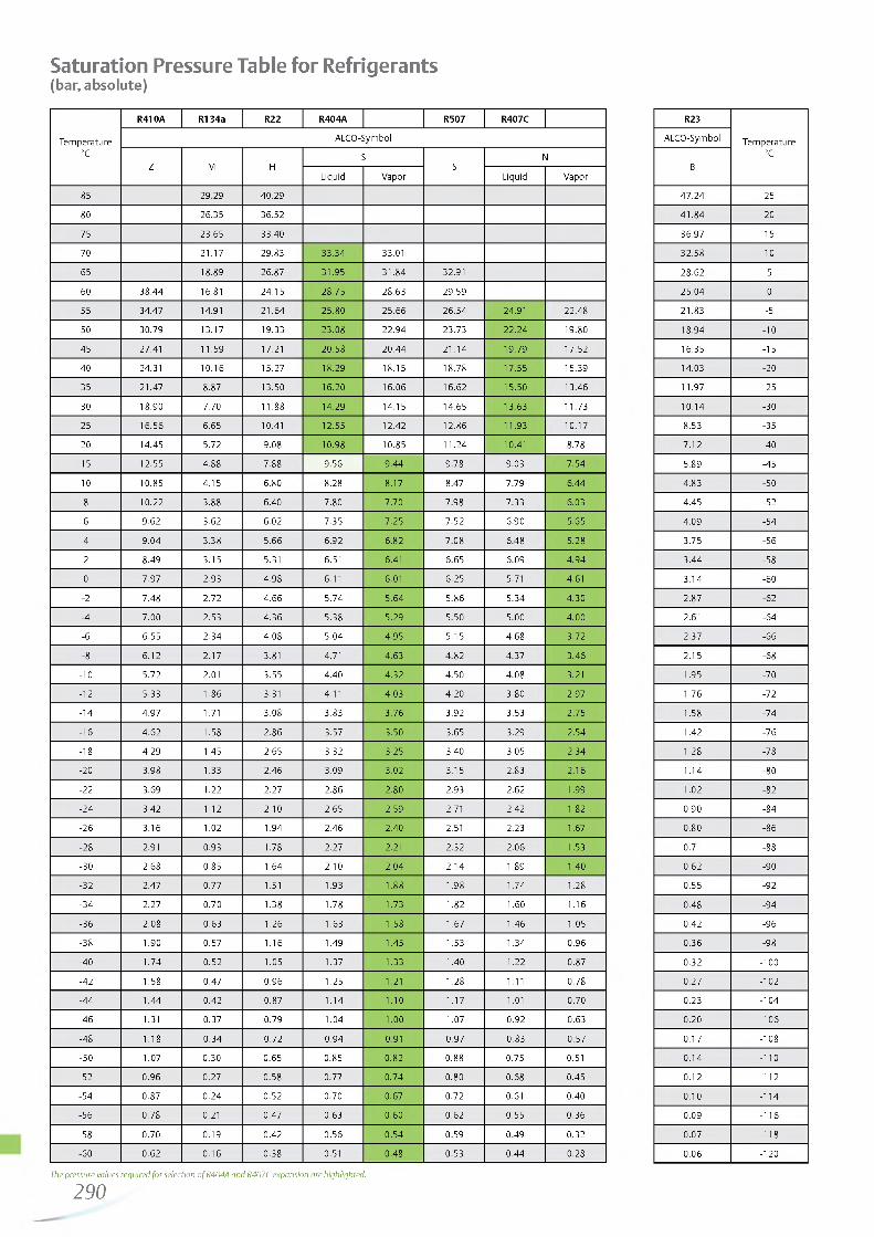
http://holodko.ru/
Saturation Pressure Table for Refrigerants(bar, absolute)
Te m p era tu re°C
R410A R134a R22 R404A R507 R407C
A LCO -Sym bo l
Z M HS
SN
Liquid V ap or Liquid V ap o r
85 2 9 .2 9 4 0 .2 9
80 2 6 .3 5 3 6 .5 2
75 2 3 .6 5 3 3 .4 0
70 2 1 .1 7 2 9 .8 3 3 3 .3 4 33.01
65 1 8 .8 9 2 6 .8 7 3 1 .9 5 3 1 .8 4 32.91
60 3 8 .4 4 16.81 2 4 .1 5 2 8 .7 5 2 8 .6 3 2 9 .5 9
55 3 4 .4 7 14.91 2 1 .6 4 2 5 .8 0 2 5 .6 6 2 6 .5 4 24.91 2 2 .4 8
50 3 0 .7 9 1 3 .1 7 1 9 .3 3 2 3 .0 8 2 2 .9 4 2 3 .7 3 2 2 .2 4 1 9 .8 0
45 27.41 1 1 .5 9 17.21 2 0 .5 8 2 0 .4 4 2 1 .1 4 1 9 .7 9 1 7 .5 2
40 24.31 1 0 .1 6 1 5 .2 7 1 8 .2 9 1 8 .1 5 1 8 .7 8 1 7 .5 5 1 5 .3 9
35 2 1 .4 7 8 .87 1 3 .5 0 1 6 .2 0 1 6 .0 6 1 6 .6 2 1 5 .5 0 1 3 .4 6
30 1 8 .9 0 7 .7 0 1 1 .8 8 1 4 .2 9 1 4 .1 5 1 4 .6 5 1 3 .6 3 1 1 .7 3
25 1 6 .5 6 6 .65 10.41 1 2 .5 5 1 2 .4 2 1 2 .8 6 1 1 .9 3 1 0 .1 7
20 1 4 .4 5 5 .72 9 .0 8 1 0 .9 8 10 .8 5 1 1 .2 4 10.41 8 .78
15 1 2 .5 5 4 .8 8 7 .8 8 9 .5 6 9 .4 4 9 .7 8 9 .0 3 7 .5 4
10 1 0 .8 5 4 .1 5 6 .80 8 .28 8 .17 8 .47 7 .7 9 6 .4 4
8 1 0 .2 2 3 .88 6 .40 7 .8 0 7 .7 0 7 .9 8 7 .3 3 6 .03
6 9 .6 2 3 .62 6 .02 7 .3 5 7 .2 5 7 .5 2 6 .9 0 5 .6 5
4 9 .0 4 3 .3 8 5 .6 6 6 .9 2 6 .8 2 7 .0 8 6 .4 8 5 .2 8
2 8 .4 9 3 .1 5 5.31 6.51 6.41 6 .6 5 6 .0 9 4 .9 4
0 7 .9 7 2 .9 3 4 .9 8 6.11 6.01 6 .2 5 5.71 4 .61
-2 7 .4 8 2 .7 2 4 .6 6 5 .7 4 5 .6 4 5 .8 6 5 .3 4 4 .3 0
-4 7 .0 0 2 .5 3 4 .3 6 5 .3 8 5 .2 9 5 .5 0 5 .0 0 4 .0 0
-6 6 .5 5 2 .3 4 4 .0 8 5 .0 4 4 .9 5 5 .1 5 4 .6 8 3 .7 2
-8 6 .1 2 2 .1 7 3.81 4 .71 4 .6 3 4 .8 2 4 .3 7 3 .4 6
-10 5 .7 2 2.01 3 .5 5 4 .4 0 4 .3 2 4 .5 0 4 .0 8 3.21
-12 5 .3 3 1 .8 6 3.31 4 .11 4 .0 3 4 .2 0 3 .8 0 2 .9 7
-14 4 .9 7 1.71 3 .0 8 3 .8 3 3 .7 6 3 .9 2 3 .5 3 2 .7 5
-16 4 .6 2 1 .58 2 .8 6 3 .57 3 .50 3 .65 3 .29 2 .5 4
-18 4 .2 9 1 .45 2 .65 3 .32 3 .25 3 .40 3 .05 2 .3 4
-20 3 .98 1 .33 2 .4 6 3 .09 3 .02 3 .15 2 .83 2 .1 6
-22 3 .69 1 .22 2 .27 2 .8 6 2 .80 2 .93 2 .62 1 .99
-24 3 .42 1 .12 2 .10 2 .65 2 .59 2.71 2 .42 1 .82
-26 3 .1 6 1 .02 1 .94 2 .4 6 2 .40 2.51 2 .23 1 .67
-28 2.91 0 .93 1 .78 2 .27 2.21 2 .32 2 .0 6 1 .53
-30 2 .68 0 .85 1 .64 2 .10 2 .0 4 2 .1 4 1 .89 1 .40
-32 2 .4 7 0 .7 7 1.51 1 .93 1 .88 1 .98 1 .7 4 1 .28
-34 2 .2 7 0 .7 0 1 .38 1 .78 1 .73 1 .82 1 .60 1 .1 6
-36 2 .0 8 0 .6 3 1 .2 6 1 .63 1 .58 1 .67 1 .4 6 1 .05
-38 1 .90 0 .5 7 1 .1 6 1 .49 1 .45 1 .53 1 .3 4 0 .9 6
-40 1 .7 4 0 .5 2 1 .05 1 .37 1 .33 1 .40 1 .22 0 .8 7
-42 1 .58 0 .4 7 0 .9 6 1 .25 1.21 1 .28 1.11 0 .7 8
-44 1 .4 4 0 .4 2 0 .8 7 1 .1 4 1 .10 1 .17 1.01 0 .7 0
-46 1.31 0 .3 7 0 .7 9 1 .0 4 1 .00 1 .07 0 .9 2 0 .6 3
-48 1 .18 0 .3 4 0 .7 2 0 .9 4 0.91 0 .9 7 0 .8 3 0 .5 7
-50 1 .07 0 .3 0 0 .6 5 0 .8 5 0 .8 2 0 .8 8 0 .7 5 0.51
-52 0 .9 6 0 .2 7 0 .5 8 0 .7 7 0 .7 4 0 .8 0 0 .6 8 0 .4 5
-54 0 .8 7 0 .2 4 0 .5 2 0 .7 0 0 .6 7 0 .7 2 0.61 0 .4 0
-56 0 .7 8 0.21 0 .4 7 0 .6 3 0 .6 0 0 .6 2 0 .5 5 0 .3 6
-58 0 .7 0 0 .1 9 0 .4 2 0 .5 6 0 .5 4 0 .5 9 0 .4 9 0 .3 2
-60 0 .6 2 0 .1 6 0 .3 8 0.51 0 .4 8 0 .5 3 0 .4 4 0 .28
The pressure values required fo r selection o f R404A and R407C expansion are highlighted.
2 9 0
R23
Te m p era tu re°C
A LCO -Sym bo l
B
4 7 .2 4 25
4 1 .8 4 20
3 6 .9 7 15
3 2 .5 8 10
2 8 .6 2 5
2 5 .0 4 0
2 1 .8 3 -5
1 8 .9 4 -10
1 6 .3 5 -15
1 4 .0 3 -20
1 1 .9 7 -25
1 0 .1 4 -30
8 .5 3 -35
7 .1 2 -40
5 .8 9 -45
4 .8 3 -50
4 .4 5 -52
4 .0 9 -54
3 .7 5 -56
3 .4 4 -58
3 .1 4 -60
2 .8 7 -62
2.61 -64
2 .3 7 -66
2 .1 5 -68
1 .95 -70
1 .7 6 -72
1 .58 -74
1 .42 -76
1 .28 -78
1 .1 4 -80
1 .02 -82
0 .9 0 -84
0 .8 0 -86
0.71 -88
0 .6 2 -90
0 .5 5 -92
0 .4 8 -94
0 .4 2 -96
0 .3 6 -98
0 .3 2 -100
0 .2 7 -102
0 .2 3 -104
0 .2 0 -106
0 .1 7 -108
0 .1 4 -110
0 .1 2 -112
0 .1 0 -114
0 .0 9 -116
0 .0 7 -118
0 .0 6 -120

http://holodko.ru/
CE per Pressure Vessel Directive CE 97 / 23 / EC
Filter DriersProduct Fluid Volume TS PS Hazard Conformity Marking
group (liter) (°C) (bar) category assessmentmodule
ADK-03 / 05 / 08 / 1 6 . II 0.1 ... 0.38 45 SEP - HP & ULADK-30 / 41 / 7 5 . II 0.4 ... 0.65 45 SEP - HP & ULFDB-03 / 05 / 08 / 1 6 . II 0.1 ... 0.38
-40 ... +6545 SEP - HP & UL
FDB-30 / 4 1 . II 0.45 ... 0.5 45 SEP - HP & ULBFK-05 / 08 / 1 6 . II 0.18 ... 0.32 45 SEP - HP & ULBFK-30. II 0.4 45 SEP - HP & UL
FDS-24. II 1.0 SEP - HP & ULADKS-48. II 2.1
-10 ... +65 (-45 ... -10)
34.5(25.9)
I A CE & ULADKS-96. II 3.8 I A CE & ULADKS-144. II 5.4 I A CE & ULADKS-192. II 7.0 I D1 CE0036&ULASD/ASF-28.../35./ 4 5 . II <1.0
-45 ... +50 27.5SEP - HP & UL
ASD/ASF50./75. II <1.4 SEP - HP & UL
BTAS-2. II 0.42 SEP - HP & ULBTAS-3. II 1.1
-45 ... +50 24SEP - HP & UL
BTAS-4. II 1.97 SEP - HP & ULBTAS-5. II 3.19 I A CE & UL
Oil Management / Components
OSH-4O4 II 2.0 I A HP & ULOSH-4O5 II 2.4 I A HP & ULOSH-4O7 II 2.8 I A HP & ULOSH-4O9 II 3.0 I A HP & ULOSH-411 / -413 II 3.6 I A HP & ULOST-4O4 II 1.8
-40 ... +65 31I A HP & UL
OST-4O5 II 2.6 I A HP & ULOSH-4O7 II 3.2 I A CE & ULOST-4O9 / -411 / -413 II 3.8 I A CE & ULOSH-611 II 6.5 II D1 CE & ULOSH-613 / -617 II 7.9 II D1 CE0036 & ULOSB-613 /-617 II 7.8 II D1 HP & UL
OM3 II DN 6MM -20 ... +80°C 35 SEP C E u nd er Lo w V o ltag e and EM C D irective
OM 4& OW4 II DN 6MM -20 ... +80°C 60 SEP C E u nd er Lo w V o ltag e and EM C D irective
Suction Accumulators
A08-304 II 0.9 SEP - HP & ULA10-305 II 1.1 SEP - HP & ULA12-305 / -306 II 1.3 -10 ... +65 20.7 SEP - HP & ULA14-305 / -306 II 1.6 (-45 ...10) (15.5) SEP - HP & ULA06-404 / -405 II 1.2 SEP - HP & UL
A10-405 / -406 II 2.1 SEP - HP & UL
291

http://holodko.ru/
Suction Accumulators (continued)Product Fluid
groupVolume
(liter)TS
(°C)
PS(bar)
Hazardcategory
Conformityassessment
module
Marking
A09-506 / -507 II 2.7 I A CE & ULA12-506 / -507 II 3.8 I A CE & ULA13-507 / -509 II 4.3 I A CE & ULA17-509 / -511 II 5.4 I A CE & ULA11-607 II 5.1 -10 ... +65 20.7 I A CE & UL
A13-607 / -609 II 5.8 (-45 ... -10) (15.5) I A CE & ULA14-611 II 6.4 I A CE & ULA17-613 II 7.9 I A CE & ULA20-613 II 9.4 I A CE & ULA25-613 II 11.6 II D1 CE0036& UL
Pressure SwitchesProduct Fluid Volume TS PS Hazard Conformity Marking
group (liter) (°C) (bar) category assessmentmodule
PS1-B3..., PSA-B3... 6 IV B, D CE0035& ULPS1-S3..., PSA-S3... 6 22 IV B, D CE0035& ULPS1-W3..., PSA-W3... 6 IV B, D CE0035& ULPS1-B5..., PSA-B5... 6 -50 ... +70 IV B, D CE0035& ULPS1-S5..., PSA-S5... 6 32 IV B, D CE0035& ULPS1-W5..., PSA-W5... 6 IV B, D CE0035& ULAll other PS1 types 6 22/32 Under LVD, excluded from PED CE & ULPS2-B7..., PSB-B7... 6 IV B, D CE0035& UL
PS2-C7..., PSB-C7... 6 22 IV B, D CE0035& ULPS2-T7..., PSB-T7... 6 IV B, D CE0035& ULPS2-B7..., PSB-B7... 6 IV B, D CE0035& ULPS2-C7..., PSB-C7... 6 IV B, D CE0035& ULPS2-C8..., PSB-C8... 6 50 ... +70 IV B, D CE0035& ULPS2-G8..., PSB-G8... 6 32 IV B, D CE0035& ULPS2-S8..., PSB-S8... 6 IV B, D CE0035& UL
PS2-T7..., PSB-T7... 6 IV B, D CE0035& ULPS2-W7..., PSB-W7... 6 IV B, D CE0035& ULAll other PS2 types 6 22/32 Under LVD, excluded from PED CEPS3-B.1...,PS3-W.1... 6 -40 ... +70 27 IV B, D CE0035& ULPS3-B.4...,PS3-S.4... 6 IV B, D CE0035& ULPS3-B.5...,PS3-S.5... 6 -40 ... +70 IV B, D CE0035& ULPS3-W.4...,PS3-W.5... 6 32 IV B, D CE0035& ULPS3-C.4...,PS3-T.4...,PS3-X.4... 6
-40 ... +150IV B, D CE0035& UL
PS3-C.5...,PS3-T.5...,PS3-X.5... 6 IV B, D CE0035& ULPS3-B6...,PSC-B6... 6 IV B, D CE0035& ULPS3-W6...,PSC-W6... 6 -40 ... +150 43 IV B, D CE0035& ULPS3-S6...,PSC-S6... 6 IV B, D CE0035& ULAll other PS3 type 6 -40 ... +70 27/32 Under LVD, excluded from PED CEFD113... 6 Under LVD, excluded from PED CE & UL
LVD = Low Voltage Directive
292—

http://holodko.ru/
Fan Speed Controllers
Product Fluidgroup
DN(mm)
TS
(°C)
PS(bar)
Hazardcategory
Conformityassessment
module
Marking
FSY-41 . II 6-20 ... +70
27under LVD,
excluded from PED
CEFSY-42 . II 6 32 CEFSY-43... II 6 43 CE
Transmitters
PT5-07M/T II 6-40 ... +80
mobile applic.: -25 ... +80
27 SEP - CEPT5-18M/T II 6 55 SEP - CEPT5-30M/T II 6 60 SEP - CEPT5-50M/T II 6 100 SEP - CE
Thermo® Expansion Valves and Electrical Control Valves
TI II max. 16
-45 ... +65
45 SEP - -TX3 II max. 16 45 SEP - -TX6-H/M/N/S.. II max. 22 31 SEP - -TX6-Z.. II max. 22 42 SEP - -T-series II max. 28 31 SEP - -L-series II max. 28 31 SEP - -935-series II max. 28 31 SEP - -ZZ-series II max. 28 -120 ... +65 31 SEP - -EX2 II max. 12 -40 ... +50 40 SEP - -EX4/EX5/EX6 II max. 22
-50 ... +10045 SEP - -
EX7 II 35 45 I A CEEX8 II 42 45 I A CE
Solenoid Valves
110 RB 2 . II 6....10
--40 ... +120
31 SEP - -200 RB 3 /4 /6 . II 10 ... 16 31 SEP - -240 RA 8 /9 /1 2 . II 16 ... 28 31 SEP - -240 RA 16T9 II 28 31 SEP - -240 RA 16T11 II 35 31 I A CE240 RA 20T11/13/17 . II 35 ... 54 31 I A CE540 RA 8/9/12/16 . II 16 ... 28 31 SEP - -540 RA 20T11 II 35 ... 54 28 SEP - -M36-078 II 28
-40 ... +12035 SEP - -
M36-118 II 28 35 SEP - -
Regulators
ACP II 06.
--40 ... +120 -30... +80
31 SEP - -CPHE... II 12 ... 28 28 SEP - -PRE/PRC II 16 ... 35 25 SEP - -
Ball valves
BVE/BVS... II < 28--40 ... +120
45 SEP - -BVE/BVS.. II > 35 45 I A CE
293

http://holodko.ru/
294___ —

http://holodko.ru/
Standard Terms and Conditions Of Sale - Products & Services Emerson Climate Technologies GmbH, Emerson Retail Services Europe GmbH
1. DEFINITIONS:In these Terms and Conditions of Sale, “Seller" means one of the three Emerson companies mentioned in the title; “Buyer" means the person, firm, company or corporation by whom the order is given; “Goods" means the goods (including any Software and Documentation, as defined in Clause 9) described in Seller's Acknowledgement of Order form; “Services" means the services described in Seller's Acknowledgement of Order Form; “Contract" means the written agreement (including these Terms and Conditions) made between Buyer and Seller for the supply of the Goods and/or provision of Services; “Contract Price" means the price payable to Seller by Buyer for the Goods and/or Services and “Seller Affiliate" means an Emerson Group company which is an affiliate within the meaning of Section 15 AktG [German Stock Corporation Act].2. THE CONTRACT:2.1 All orders must be in writing and are accepted subject to these Terms and Conditions of Sale. No terms or conditions put forward by Buyer and no representations, warranties, guarantees or other statements not contained in Seller's quotation or Acknowledgement of Order nor otherwise expressly agreed in writing by Seller shall be binding on Seller.2.2 The Contract shall become effective only upon the date of acceptance of Buyer's order on Seller's Acknowledgement of Order form. If the details of the Goods or Services described in Seller's quotation differ from those set out in the Acknowledgement of Order Form the latter shall apply.2.3 No alteration or variation to the Contract shall apply unless agreed in writing by both parties. However, Seller reserves the right to effect minor modifications and/or improvements to the Goods before delivery provided that the performance of the Goods is not adversely affected and that neither the Contract Price nor the delivery date is affected.3. VALIDITY OF QUOTATION AND PRICES:3.1 Unless previously withdrawn, Seller's quotation is open for acceptance within the period stated therein or, when no period is so stated, within thirty days after its date.3.2 Prices are firm for delivery within the period stated in Seller's quotation and are exclusive of (a) Value Added Tax and (b) any similar and other taxes, duties, levies or other like charges arising outside Germany in connection with the performance of the Contract.3.3 Prices (a) are for Goods delivered EXW (Ex works) Seller's shipping point, exclusive of freight, insurance and handling and (b) unless otherwise stated in the Seller's quotation, are exclusive of packing. If the Goods are to be packed, packing materials are non-returnable.4. PAYMENT:4.1 Payment shall be made: (a) in full without set-off, counterclaim or withholding of any kind (save where and to the extent that this cannot by law be excluded); and (b) in the currency of Seller's quotation within thirty days of receipt of invoice unless otherwise specified by Seller's Finance Department. Goods will be invoiced at any time after their readiness for despatch has been notified to Buyer. Services will be invoiced monthly in arrears or, if earlier, upon completion. Without prejudice to Seller's other rights, Seller reserves the right to: (i) charge interest on any overdue sums at 8% above the base lending rate of Section 247 BGB (German Civil Code) during the period of delay; (ii) suspend performance of the Contract (including withholding shipment) in the event that Buyer fails or in Seller's reasonable opinion it appears that Buyer is likely to fail to make payment when due under the Contract or any other contract; and (iii) under the same conditions require reasonable security for payment.4.2 Customer may set off counterclaims only if recognised or non-appealable. A right of retention may be exercised by Customer only if as it concerns the same contractual relationship.5. DELIVERY PERIOD:5.1 Unless otherwise stated in Seller's quotation, all periods stated for delivery or completion run from the Effective Date and are to be treated as estimates only not involving any contractual obligations.5.2 If Seller is delayed in or prevented from performing any of its obligations under the Contract due to the acts or omissions of Buyer or its agents (including but not limited to failure to provide specifications and/or fully dimensioned working drawings and/or such other information as Seller reasonably requires to proceed expeditiously with its obligations under the Contract), the delivery/completion period and the Contract Price shall both be adjusted accordingly.5.3 If delivery is delayed due to any act or omission of Buyer, or if having been notified that the Goods are ready for despatch, Buyer fails to take delivery or provide adequate shipping instructions, Seller shall be entitled to place the Goods into a suitable store at Buyer's expense. Upon placing the Goods into the store, delivery shall be deemed to be complete, risk in the Goods shall pass to Buyer and Buyer shall pay Seller accordingly.6. FORCE MAJEURE:6.1 The Contract (other than Buyer's obligation to pay all sums due to Seller in accordance with the Contract) shall be suspended, without liability, in the event and to the extent that its performance is prevented or delayed due to any circumstance beyond the reasonable control of the party affected, including but not limited to: Act of God, war, armed conflict or terrorist attack, riot, fire, explosion, accident, flood, sabotage; governmental decisions or actions (including but not limited to prohibition of exports or re-exports or the failure to grant or the revocation of applicable export licenses), or labour trouble, strike, lockout or injunction. Seller shall have no obligation to supply hardware, software or technology or to provide services in the absence of government permits or fulfilment of statutory conditions of exemption from such permits within the framework of import and export control (in particular, according to the regulations applicable in the United States, the European Union and the jurisdiction in which Seller has its registered office or from which components of the Goods are supplied) and the underlying circumstances could not be foreseen by Seller and are outside of Seller's sphere of influence. In the event of revocation of issued government permits or in the event of a change in the applicable statutory import and export control regulations such that Seller is prevented from fulfilling the contract, Seller is discharged from the contractual obligation without any liability of Seller.6.2 If either party is delayed or prevented from performance of its obligations by reason of this Clause for more than 180 consecutive calendar days, either party may terminate the then unperformed portion of the Contract by notice in writing given to the other party, without liability provided that Buyer shall be obliged to pay the reasonable cost and expense of any work in progress and to pay for all Goods delivered and Services performed as at the date of termination.7. INSPECTION, TESTING, AND CALIBRATION:7.1 Goods will be inspected by Seller or manufacturer and, where practicable, submitted to Seller's or manufacturer's standard tests before despatch. Any additional tests or inspection (including inspection by Buyer or its representative, or tests in the presence of Buyer or its representative and/or calibration) or the supply of test certificates and/or detailed test results shall be subject to Seller's prior written agreement and Seller reserves the right to charge therefor; if Buyer or its representative fails to attend such tests, inspection and/or calibration after seven days' notice that the Goods are ready therefor, the tests, inspection and/or calibration will proceed and shall be deemed to have been made in the presence of Buyer or its representative and the Seller's statement that the Goods have passed such testing and/or inspection and/or have been calibrated shall be conclusive.7.2 Buyer's warranty rights are subject to Buyer's proper compliance with Buyer's inspection and complaint obligations set forth in Section 377 of the German Commercial Code (HGB).8. DELIVERY, RISK & TITLE:8.1 Unless otherwise expressly stated in the Contract, the Goods will be delivered Carriage Paid To (CPT) the destination named in the Contract; freight, packing and handling will be charged at Seller's standard rates. Risk of loss of or damage to the Goods shall pass to Buyer upon delivery as aforesaid and Buyer shall be responsible for insurance of the Goods after risk has so passed. Alternatively, if it is expressly stated in the Contract that Seller is responsible for the insurance of the Goods after their delivery to the carrier, such insurance will be charged at Seller's standard rates. “Ex-works', “FCA", “CPT" and any other delivery terms used in the Contract shall be defined in accordance with the latest version of Incoterms.9. DOCUMENTATION AND SOFTWARE:9.1 Title to and ownership of the copyrights in software and/or firmware incorporated into or provided for use with the Goods (“Software") and documentation supplied with the Goods (“Documentation") shall remain with the relevant Seller Affiliate (or such other party as may have supplied the Software and/or Documentation to Seller) and is not transferred hereby to Buyer.9.2 Except as otherwise provided herein, Buyer is hereby granted a non-exclusive, royalty-free licence to use the Software and Documentation in conjunction with the Goods, provided that and for so long as the Software and Documentation are not copied (unless expressly authorised by applicable law) and Buyer holds the Software and Documentation in strict confidence and does not disclose them to others, or permit others to have access to them (other than Seller's standard operating and maintenance manuals). Buyer may transfer the foregoing licence to another party which purchases, rents or leases the Goods, provided the other party accepts and agrees in writing to be bound by the conditions of this Clause 9.9.3 Notwithstanding Sub-clause 9.2, Buyer's use of certain Software, (as specified by Seller and including but not limited to control system and AMS Software) shall be governed exclusively by the applicable Seller Affiliate or third party licence agreement.9.4 Seller and Seller Affiliates shall retain ownership of all inventions, designs and processes made or evolved by them and save as set out in th is Clause 9 no rights in intellectual property are hereby granted.10. LIABILITY FOR DEFECTS OF QUALITY10.1 Seller warrants that upon passing of the risk the Goods and Services will have the quality agreed upon. Unless otherwise agreed, the quality agreed upon shall meet Seller's specifications as valid and published at the time of the order confirmation.10.2 If, upon passing of the risk, the Goods or Services do not have the quality agreed upon, Seller warrants to provide subsequent performance by either, at its option, repairing or replacing the concerned parts (subsequent rectification) or by replacing the Goods or Services by such Goods or Services which are free from defects (subsequent delivery).10.3 Seller may rectify any defect several times and may decide at its discretion to change from rectification to subsequent delivery. Seller shall be responsible for all costs incurred in connection with its subsequent performance, especially the transport, shipping, labour and material cost, unless such costs are incurred as a result of the Goods being taken to a place other than the place of performance.
10.4 Buyer may set a reasonable period of at least four (4) weeks to Seller for him to provide subsequent performance and, if subsequent performance fails during such period, may demand reduction of the Contract Price after expiry of that period or, unless the defect is insignificant, may rescind the Contract. Damages may only be claimed in line with Clause 14.10.5 Any claims and rights based on defects will become time-barred, except in the case of intent, after expiry of twelve (12) months since taking into operation of the Goods, however no later than eighteen (18) months since delivery. Claims to damages based on defects will become time-barred after expiry of the statutory period if they result from a violation of another's life, health or body, or from Seller's gross negligence.10.6 Seller assumes no warranty for normal wear and tear, material provided by Buyer, processing of the Goods made by Buyer, damage due to improper storage, installation or operation or due to inadequate maintenance, or damage resulting from any modification or repair not approved beforehand by Seller in writing. Seller will not be liable where any non-authorised software or non-authorised spare or replacement parts are used. Any costs incurred by Seller for examining and removing such defects will be borne by Buyer upon demand. Buyer will always be responsible alone for the completeness and correctness of any information provided by it.10.7 Regarding products or Services sourced by Seller from a third party (other than a Seller Affiliate) for resale to Buyer, Seller assigns to Buyer all warranty rights against such third party. In addition, Seller remains obliged to assume the guarantee set forth the preceding clauses towards Buyer, however, only under the restriction that Buyer has beforehand unsuccessfully tried to execute the assigned warranty rights against the third party.11. LIABILITY FOR PROPRIETARY RIGHTS INFRINGEMENTS11.1 Seller warrants that upon passing of the risk no patents or other proprietary rights of third parties exist which may be claimed with respect to the Goods or Services if these are used as intended. Clauses 10.2 to 10.5 and 10.7 shall apply correspondingly.11.2 Seller's liability shall be excluded where a third party patent or proprietary right is infringed because Seller has adhered to a design provided by Buyer or has complied with an instruction given by Buyer, or because the Goods are used in a manner, for a purpose, in a country, or in connection with other goods or services, without this having been communicated to Seller before execution of the Contract.11.3 During the period of Seller's warranty, Buyer has the obligation to inform Seller in writing as promptly as possible in the event that a third party claims any patent or other proprietary right or asserts any claims in or out of court with respect to the Goods or Services. Before recognising any claim advanced by a third party in or out of court, Buyer shall give Seller the opportunity to comment. At its request, Seller shall be given the authority to handle the negotiations or legal dispute with such third party at its own cost and responsibility. Buyer shall be liable to Seller for any damage sustained by it as a result of a culpable violation of said obligations.11.4 Buyer warrants that the use of a design provided by it or compliance with an instruction given by it will not lead to Seller infringing any patents or other proprietary rights when performing its contractual obligations. Buyer agrees to indemnify and hold Seller harmless against any reasonable cost and damages incurred by Seller as a result of Buyer's breach of this warranty.12. DAMAGES12.1 Seller shall be liable to Buyer only for damage caused with intent or gross negligence. In the event of breach of material contractual obligations, Seller shall, however, be liable for each fault of its personnel (statutory representatives, executive employees and other persons employed in the performance of its obligations) causing damage.12.2 Except in case of intentional causation of damage by personnel of Seller or causation of damage with gross negligence by statutory representatives or executive employees of Seller, Seller shall not be liable for compensation for indirect damage and, in particular, Seller shall not be liable for compensation for loss of profit, unless such damage is covered by the protective purpose of a warranty explicitly assumed.12.3 Except in case of intentional causation of damage by personnel of Seller or causation of damage with gross negligence by statutory representatives or executive employees of Seller, the liability of Seller shall, in each case, be limited in terms of amount to the damage which is typically foreseeable in the time of conclusion of the contract.12.4 Claims to damages which result from the violation of another's life, body or health, from the violation of a guaranty given by Seller expressly in writing as well as damage claims under the Product Liability Act shall remain unaffected.13. STATUTORY AND OTHER REGULATIONS:13.1 If Seller's obligations under the Contract shall be increased or reduced by reason of the making or amendment after the date of Seller's quotation of any law or any order, regulation or bye-law having the force of law that shall affect the performance of Seller's obligations under the Contract, the Contract Price and delivery period shall be adjusted accordingly and/or performance of the Contract suspended or terminated, as appropriate. A price adjustment shall not be implemented if the delivery is to be carried out within 4 months after the closing of the Contract.13.2 Except to the extent otherwise required by applicable law, Seller shall have no responsibility for the collection, treatment, recovery or disposal of (i) the Goods or any part thereof when they are deemed by law to be 'waste' or (ii) any items for which the Goods or any part thereof are replacements. If Seller is required by applicable law, including waste electrical and electronic equipment legislation, European Directive 2002/96/EC (WEEE) and related legislation in EU Member States, to dispose of 'waste' Goods or any part thereof, Buyer shall, unless prohibited by applicable law, pay Seller, in addition to the Contract Price, either (i) Seller's standard charge for disposing of such Goods or (ii) if Seller does not have such a standard charge, Seller's costs (including all handling, transportation and disposal costs and a reasonable mark-up for overhead) incurred in disposing of such Goods.13.3 Buyer's personnel shall, whilst on Seller's premises, comply with Seller's applicable site regulations and Seller's reasonable instructions, including but not limited to those relating to safety, security and electrostatic discharge.14. COMPLIANCE WITH LAWSBuyer agrees that all applicable import, export control and sanctions laws, regulations, orders and requirements, as they may be amended from time to time, including without limitation those of the United States, the European Union and the jurisdictions in which Seller and Buyer are established or from which items may be supplied, and the requirements of any licenses, authorisations, general licences or licence exceptions relating thereto will apply to its receipt and use of hardware, software, services and technology. In no event shall Buyer use, transfer, release, export or re-export any such hardware, software or technology in violation of such applicable laws, regulations, orders or requirements or the requirements of any licences, authorisations or licence exceptions relating thereto. Buyer agrees furthermore that it shall not engage in any activity that would expose the Seller or any of its affiliates to a risk of penalties under laws and regulations of any relevant jurisdiction prohibiting improper payments, including but not limited to bribes, to officials of any government or of any agency, instrumentality or political subdivision thereof, to political parties or political party officials or candidates for public office, or to any employee of any customer or supplier. Buyer agrees to comply with all appropriate legal, ethical and compliance requirements.15. DEFAULT, INSOLVENCY AND CANCELLATION:Seller shall be entitled, without prejudice to any other rights it may have, to cancel the Contract forthwith, wholly or partly, by notice in writing to Buyer, if Buyer is in default of any of its obligations under the Contract and fails, within 30 (thirty) days of the date of Seller's notification in writing of the existence of the default, either to rectify such default if it is reasonably capable of being rectified within such period or, if the default is not reasonably capable of being rectified within such period, to take action to remedy the default.16. SUPPLEMENTARY TERMS AND CONDITIONS:If the Goods comprise or include a control system, Seller's Supplementary Terms and Conditions Applicable to the Supply of Control Systems and Related Services shall apply to the control system and related services only. Such Supplementary Terms and Conditions shall take precedence over these Standard Terms and Conditions of Sale; copies are available from Seller upon request.17. MISCELLANEOUS:17.1 No waiver by either party with respect to any breach or default or of any right or remedy and no course of dealing, shall be deemed to constitute a continuing waiver of any other breach or default or of any other right or remedy, unless such waiver be expressed in writing and signed by the party to be bound.17.2 If any clause, sub-clause or other provision of the Contract is invalid or unenforceable, this shall not affect the validity of the remainder of the Contract. Should one of the clauses be invalid or unenforceable, the parties obligate themselves to replace the invalid or unenforceable clause by such a clause which comes closest to the intended economic purpose of the invalid clause.17.3 Buyer shall not be entitled to assign its rights or obligations hereunder without the prior written consent of Seller.17.4 Seller enters into the Contract as principal. Buyer agrees to look only to Seller for due performance of the Contract.17.5 GOODS AND SERVICES PROVIDED HEREUNDER ARE NOT SOLD OR INTENDED FOR USE IN ANY NUCLEAR OR NUCLEAR RELATED APPLICATIONS. Buyer (i) accepts Goods and Services in accordance with the foregoing restriction, (ii) agrees to communicate such restriction in writing to any and all subsequent purchasers or users and (iii) agrees to defend, indemnify and hold harmless Seller and Seller's Affiliates from any and all claims, losses, liabilities, suits, judgements and damages, including incidental and consequential damages, arising from use of Goods and Services in any nuclear or nuclear related applications, whether the cause of action be based in tort, contract or otherwise, including allegations that the Seller's liability is based on negligence or strict liability.17.6 The Contract shall in all respects be construed in accordance with the laws of the Federal Republic of Germany excluding, however, any effect on such laws of the 1980 Vienna Convention on Contracts for the International Sale of Goods, and to the fullest extent permitted by law, shall be without regard to any conflict of laws or rules which might apply the laws of any other jurisdiction. All disputes arising out of the Contract shall be subject to the exclusive jurisdiction of the Berlin courts. However, Seller is entitled to sue Buyer in the court of Buyer's residence as well.17.7 The headings to the Clauses and paragraphs of the Contract are for guidance only and shall not affect the interpretation thereof.17.8 All notices and claims in connection with the Contract must be in writing.
Emerson Clim ate Technologies GmbHRegistered Office:Am tsgericht Berlin-Charlottenburg, HRB 877B
Emerson Retail Services Europe Gm bHRegistered Office:Am tsgericht Berlin-Charlottenburg, HRB 81171
295

http://holodko.ru/
SGE1
27-E
N-13
01
BENELUX UK & IRELAND BALKANDeltakade 7 Unit 17, Theale Lakes Business Park Selska cesta 93NL-5928 PX Venlo Reading, Berks RG7 4GB HR-10 000 ZagrebTel. +31 77 324 02 34 Tel: +44 1189 83 80 00 Tel. +385 1 560 38 75Fax +31 77 324 02 35 Fax: +44 1189 83 80 01 Fax +385 1 560 38 [email protected] [email protected] [email protected]
GERMANY, AUSTRIA & SWITZERLANDSenefelder Str. 3DE-63477 MaintalTel. +49 6109 605 90Fax +49 6109 60 59 [email protected]
SWEDEN, DENMARK, NORWAY & FINLANDPascalstr. 65DE-52076 AachenTel. +49 2408 929 0Fax +49 2408 92 95 [email protected]
CZECH REPUBLICHajkova 2747/22CZ-13000 Prague 3Tel +420 271 035 628Fax +420 271 035 [email protected]
FRANCE, GREECE & MAGHREB 8, Allee du Moulin Berger FR-69134 Ecully Cedex Tel. +33 4 78 66 85 70Fax +33 4 78 66 85 [email protected]
EASTERN EUROPE & TURKEYPascalstr. 65DE-52076 AachenTel. +49 2408 929 0Fax +49 2408 929 [email protected]
UKRAINETurgenevskaya Str. 15, office 33 UA-01054, Kiev Tel. +38 - 44 - 4 92 99 24Fax. +38 - 44 - 4 92 99 [email protected]
ITALYVia Ramazzotti, 26 IT-21047 Saronno (VA)Tel. +39 02 96 17 81Fax +39 02 96 17 88 [email protected]
POLANDSzturmowa 2PL-02678 WarsawTel. +48 22 458 92 05Fax +48 22 458 92 [email protected]
ROMANIA
Tel. +40 - 374 -13 23 50Fax +40 - 374 -13 28 [email protected]
SPAIN & PORTUGAL C/ LLull, 321 (Edifici CINC) e S-08019 Barcelona Tel. +34 93 412 37 52Fax +34 93 412 42 [email protected]
RUSSIA & CISLetnikovskaya 10, Bld. 2, floor 5 RU-115114 Moscow Tel. +7 495 981 98 11Fax +7 495 981 98 [email protected]
MIDDLE EAST & AFRICA PO Box 26382Jebel Ali Free Zone - South, Dubai - UAE Tel. +971 4 811 81 00Fax +971 4 886 54 [email protected]
For more details, see www.emersonclimate.eu
Emerson Climate Technologies - European Headquarters - Pascalstrasse 65 - 52076 Aachen, Germany Tel. +49 (0) 2408 929 0 - Fax: +49 (0) 2408 929 570 - Internet: www.emersonclimate.eu
The Emerson Climate Technologies logo is a trademark and service mark of Emerson Electric Co. Emerson Climate Technologies Inc. is a subsidiary of Emerson Electric Co. Copeland is a registered trademark and Copeland Scroll is a trademark of Emerson Climate Technologies Inc.. All other trademarks are property of their respective owners. Emerson Climate Technologies GmbH shall not be liable for errors in the stated capacities, dimensions, etc., as well as typographic errors. Products, specifications, designs and technical data contained in this document are subject to modification by us without prior notice. Illustrations are not binding.© 2012 Emerson Climate Technologies, Inc.
EMERSONClimate Technologies
E M E R S O N . C O N S I D E R I T S O L V E D