General Model RAMC Specifications Metal Short-stroke Rotameter · Metal Short-stroke Rotameter A...
20
RAMC with housing type 90 RAMC with housing type 91 GS 01R01B02-00E-E © Copyright Oct. 2004 (Rü) 17th edition, June 2008 (Rü) Model RAMC Metal Short-stroke Rotameter A float is guided concentrically to a special shaped conic metal tube. The position of this float is magnetically transmitted to the indicator. The short-tube Rotameter is used for measurement of flow rates of liquids and gases. Its special application is in troubled, opaque or aggressive mediums. The instrument is mounted in a vertical pipeline with flow direction upwards. The indicators are exchangeable without influence on the accuracy. FEATURES - Different process connections like flanges according EN and ASME - All wetted parts in stainless steel or PTFE - Maximum flow 0.025 - 130 m³/h water resp. 0.75 - 1400 m³/h air (20 °C / 1.013 bar abs) - Accuracy class 1.6 resp. 2.5 with lining acc. VDI/VDE 3513 - Float damping to avoid float bouncing with gas applications - Optional heat tracing (with steam or fluid heat carrier) - Indicator in stainless steel, aluminium or plastic, protection class IP66/67 or IP65 - Local indicator without additional power supply - Microprocessor controlled transmitter with 24 V, 115 V or 230 V power supply - Intrinsically safe version (Ex-i) (ATEX, FM/CSA, SAA, NEPSI) - Flame proof version (Ex-d) (ATEX, NEPSI) - Dust explosion proof (ATEX, NEPSI) - Suitable for SIL application, FMEDA report on request - Limit switches, also available as “Fail Safe” version Electronic transmitter as standard with local-controlling display with the following features : - Flow indication (totalize, actual, percent) - Indication of different volume- and mass flow units - Second (manual) calibration storing - Patented float blocking indication function - Signal output damping - Error message indication - Temperature measurement in the electronic transmitter - HART- communication - Profibus PA - communication Contents Features page 1 Standard Specifications page 2 Hazardous Area Specifications page 4 Installation page 7 Model Specifications page 11 Options page 12 Process connection table for metal tubes page 13 Flow tables metal tubes page 14 Process connection and flow table for tubes with PTFE lining page 15 Temperature graphs page 16 Dimensions and weights page 17 General Specifications Rota Yokogawa GmbH & Co. KG Rheinstr. 8 D-79664 Wehr Germany GS 01R01B02-00E-E
Transcript of General Model RAMC Specifications Metal Short-stroke Rotameter · Metal Short-stroke Rotameter A...
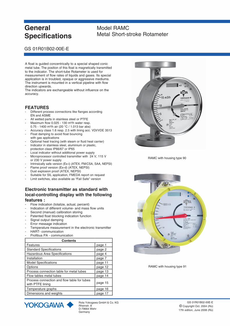
RAMC with housing type 90
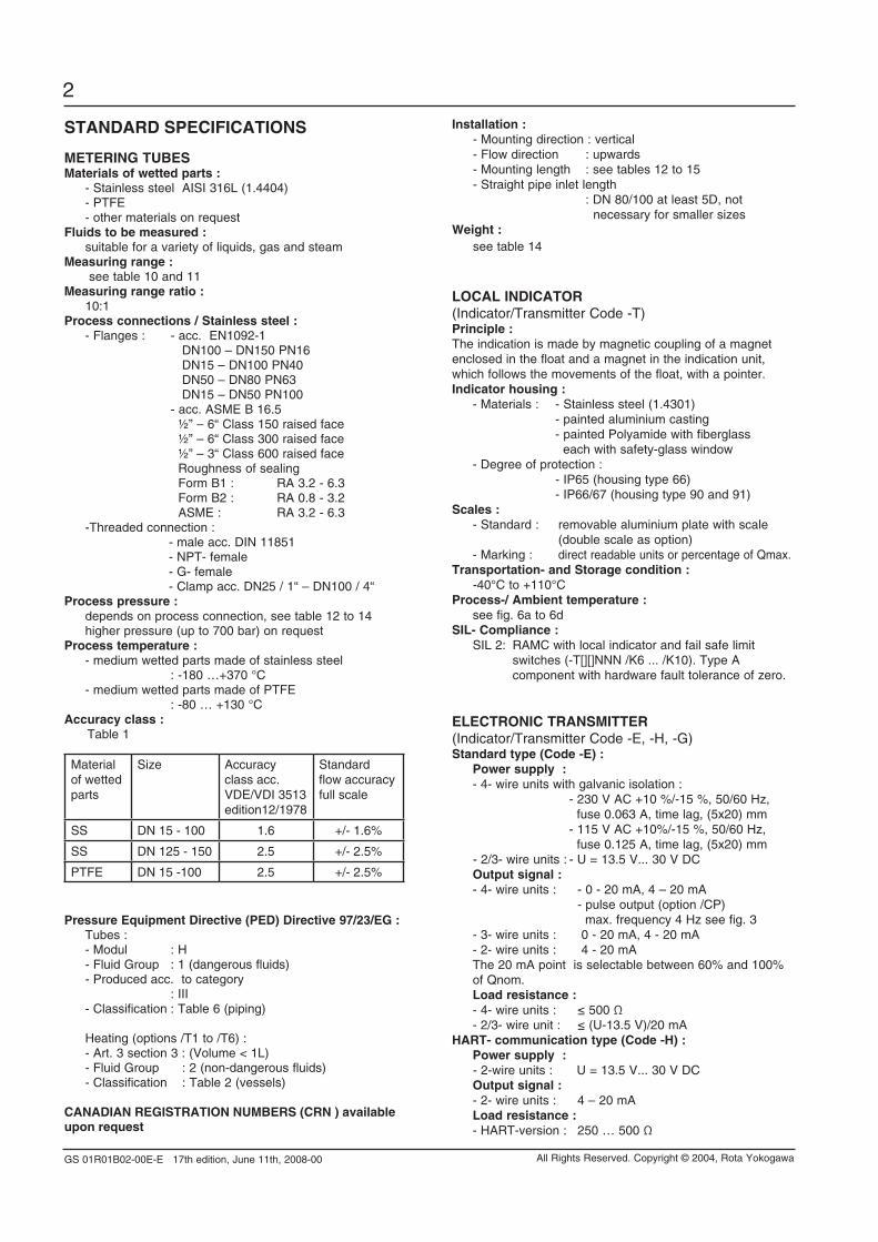
RAMC with housing type 91
GS 01R01B02-00E-E© Copyright Oct. 2004 (Rü)17th edition, June 2008 (Rü)
Model RAMCMetal Short-stroke Rotameter
A float is guided concentrically to a special shaped conic metal tube. The position of this float is magnetically transmitted to the indicator. The short-tube Rotameter is used for measurement of flow rates of liquids and gases. Its special application is in troubled, opaque or aggressive mediums. The instrument is mounted in a vertical pipeline with flow direction upwards.The indicators are exchangeable without influence on theaccuracy.
FEATURES- Different process connections like flanges according EN and ASME- All wetted parts in stainless steel or PTFE- Maximum flow 0.025 - 130 m³/h water resp. 0.75 - 1400 m³/h air (20 °C / 1.013 bar abs)- Accuracy class 1.6 resp. 2.5 with lining acc. VDI/VDE 3513- Float damping to avoid float bouncing with gas applications- Optional heat tracing (with steam or fluid heat carrier)- Indicator in stainless steel, aluminium or plastic, protection class IP66/67 or IP65- Local indicator without additional power supply- Microprocessor controlled transmitter with 24 V, 115 V or 230 V power supply- Intrinsically safe version (Ex-i) (ATEX, FM/CSA, SAA, NEPSI) - Flame proof version (Ex-d) (ATEX, NEPSI) - Dust explosion proof (ATEX, NEPSI)- Suitable for SIL application, FMEDA report on request - Limit switches, also available as “Fail Safe” version
Electronic transmitter as standard with local-controlling display with the following features :- Flow indication (totalize, actual, percent)- Indication of different volume- and mass flow units- Second (manual) calibration storing- Patented float blocking indication function- Signal output damping- Error message indication- Temperature measurement in the electronic transmitter- HART- communication- Profibus PA - communication
ContentsFeatures page 1Standard Specifications page 2Hazardous Area Specifications page 4Installation page 7Model Specifications page 11Options page 12Process connection table for metal tubes page 13Flow tables metal tubes page 14Process connection and flow table for tubes with PTFE lining page 15
Temperature graphs page 16Dimensions and weights page 17
GeneralSpecifications
Rota Yokogawa GmbH & Co. KGRheinstr. 8D-79664 WehrGermany
GS 01R01B02-00E-E
GS 01R01B02-00E-E 17th edition, June 11th, 2008-00
2
All Rights Reserved. Copyright © 2004, Rota Yokogawa
STAndARd SpECiFiCATionS
METERinG TUbESMaterials of wetted parts : - Stainless steel AISI 316L (1.4404) - PTFE - other materials on requestFluids to be measured : suitable for a variety of liquids, gas and steamMeasuring range : see table 10 and 11Measuring range ratio : 10:1process connections / Stainless steel : - Flanges : - acc. EN1092-1 DN100 – DN150 PN16 DN15 – DN100 PN40 DN50 – DN80 PN63 DN15 – DN50 PN100 - acc. ASME B 16.5 ½” – 6“ Class 150 raised face ½” – 6“ Class 300 raised face ½” – 3“ Class 600 raised face Roughness of sealing Form B1 : RA 3.2 - 6.3 Form B2 : RA 0.8 - 3.2 ASME : RA 3.2 - 6.3 -Threaded connection : - male acc. DIN 11851 - NPT- female - G- female - Clamp acc. DN25 / 1“ – DN100 / 4“process pressure : depends on process connection, see table 12 to 14 higher pressure (up to 700 bar) on request process temperature : - medium wetted parts made of stainless steel : -180 …+370 °C - medium wetted parts made of PTFE : -80 … +130 °CAccuracy class : Table 1
Material of wetted parts
Size Accuracy class acc. VDE/VDI 3513edition12/1978
Standard flow accuracy full scale
SS DN 15 - 100 1.6 +/- 1.6%
SS DN 125 - 150 2.5 +/- 2.5%
PTFE DN 15 -100 2.5 +/- 2.5%
pressure Equipment directive (pEd) directive 97/23/EG : Tubes : - Modul : H - Fluid Group : 1 (dangerous fluids) - Produced acc. to category : III - Classification : Table 6 (piping) Heating (options /T1 to /T6) : - Art. 3 section 3 : (Volume < 1L) - Fluid Group : 2 (non-dangerous fluids) - Classification : Table 2 (vessels)
CAnAdiAn REGiSTRATion nUMbERS (CRn ) available upon request
installation : - Mounting direction : vertical - Flow direction : upwards - Mounting length : see tables 12 to 15 - Straight pipe inlet length : DN 80/100 at least 5D, not necessary for smaller sizesWeight : see table 14
LoCAL indiCAToR(Indicator/Transmitter Code -T)principle : The indication is made by magnetic coupling of a magnet enclosed in the float and a magnet in the indication unit, which follows the movements of the float, with a pointer.indicator housing : - Materials : - Stainless steel (1.4301) - painted aluminium casting - painted Polyamide with fiberglass each with safety-glass window - Degree of protection : - IP65 (housing type 66) - IP66/67 (housing type 90 and 91)Scales : - Standard : removable aluminium plate with scale (double scale as option) - Marking : direct readable units or percentage of Qmax.Transportation- and Storage condition : -40°C to +110°C process-/ Ambient temperature : see fig. 6a to 6d SiL- Compliance : SIL 2: RAMC with local indicator and fail safe limit switches (-T[][]NNN /K6 ... /K10). Type A component with hardware fault tolerance of zero.
ELECTRoniC TRAnSMiTTER(Indicator/Transmitter Code -E, -H, -G)Standard type (Code -E) : power supply : - 4- wire units with galvanic isolation : - 230 V AC +10 %/-15 %, 50/60 Hz, fuse 0.063 A, time lag, (5x20) mm - 115 V AC +10%/-15 %, 50/60 Hz, fuse 0.125 A, time lag, (5x20) mm - 2/3- wire units : - U = 13.5 V... 30 V DC output signal : - 4- wire units : - 0 - 20 mA, 4 – 20 mA - pulse output (option /CP) max. frequency 4 Hz see fig. 3 - 3- wire units : 0 - 20 mA, 4 - 20 mA - 2- wire units : 4 - 20 mA The 20 mA point is selectable between 60% and 100% of Qnom. Load resistance : - 4- wire units : ≤ 500 Ω - 2/3- wire unit : ≤ (U-13.5 V)/20 mAHART- communication type (Code -H) : power supply : - 2-wire units : U = 13.5 V... 30 V DC output signal : - 2- wire units : 4 – 20 mA Load resistance : - HART-version : 250 … 500 Ω
GS 01R01B02-00E-E 17th edition, June 11th, 2008-00
3
All Rights Reserved. Copyright © 2004, Rota Yokogawa
profibus pA - communication type (Code -G) : - 2- wire bus connection not polarity sensitive : 9 ... 32V DC acc. to IEC 61568-2 and FISCO model - Basic current : 14 mA - Failure current (FDE) : 10mA additional to basic current - Transmission rate : 31.25 kBaud - AI block for volume flow or mass flow - Configurable with PDM DD - Supports I&M- functions digital display : 8- digits 7- segment-LC-display character height 6 mmprocess-/ Ambient temperature : The dependency of the process temperature from the ambient temperature is shown in fig. 7a to fig. 7d. The internal temperature of the electronic transmitter can be indicated on the display or checked via HART communication.Measurement of the internal transmitter temperature : - Range : -25 °C to +70 °C - Accuracy : ± 5 °CTransportation- and Storage condition : -40 °C to +70 °CLinearity 1) : ± 0.2 % f.s.Hysteresis 1) : ± 0.1 % f.s.Repeatability 1) : ± 0.1 % f.s.influence of power supply 1) : ± 0.1 % f.s.Temperature coefficient of the output signal 1) : ± 0.5 %/10 K f.s.AC-part of output signal 1) : ± 0.15 % f.s.Long-time stability 1) : ± 0.2 % /yearMax. output signal : 21.5 mAoutput signal in case of failure : ≤ 3.6 mA (acc. NE 43)Response time (99%) : About 1.5 s (damping 1s)Electromagnetic compatibility (EMC) : - Emission acc. EN 55011: 2003 : class B, group 1 - EN 61000-3-2: 2001 - EN 61000-3-3: 2002 - Immunity acc. EN 61326: 2002 : Criterion A, restriction: HF- immunity between 500 MHz and 750 MHz : criterion B RAMC with Profibus PA : Criterion A: Burst, Surge, HF- Immunity Criterion B: ESD In case of single sided grounding of the cable shield it is possible that for all tests criterion B is reached.Unit safety acc. din En 61010-1 : 2002 : - Over voltage category : II (acc. VDE 0110 or IEC 664) - Pollution degree : I - Safety class : I (with 115 / 230V AC power supply) III (with 24V DC power supply and Fieldbus type)SiL- Compliance : SIL 1: RAMC with 4-20mA output (-E[][]424 and -H[][]424) Type B component with hardware fault tolerance of zero.
poWER SUppLY FoR ELECTRoniC TRAnSMiTTER (Option /U__)Type : power supply with galvanically separated input and output - SINEAX B811, HART- compatible type availableSupply voltage : - 24 V to 60 V AC/DC - 85 V to 230 V AC Maximum load : 750 Ωoutput signal : 0/4 mA - 20 mA
CAbLE GLAnd (for transmitter –E, -H and –G) :Size : - M16x1.5 (standard) - Thread M20x1.5 (option /A13; standard for option /KF1) - Thread ½” NPT (option /A5)Cable diameter : 6 – 9 mmMaximum cross section of core : Ø 1.5 mm²
LiMiT SWiTCHES in STAndARd vERSion (option /K1 to /K3)Type : Inductive proximity switch SC3.5-NO acc. DIN EN 60947-5-6 nominal voltage : 8 V DCoutput signal : ≤ 1 mA or ≥ 3 mA
LiMiT SWiTCHES in FAiL SAFE vERSion (option /K6 to /K10)Type : Inductive proximity switch SJ3.5-SN; SJ3.5-S1N acc. DIN EN 60947-5-6 (NAMUR)nominal voltage : 8 V DCoutput signal : ≤ 1 mA or ≥ 3 mA
HYSTERESiS oF LiMiT SWiTCHESMin-contact : - pointer movement ≈ 0.5 mm - float movement ≈ 0.8 mmMax-contact : - pointer movement ≈ 0.5 mm - float movement ≈ 0.6 mm
CAbLE GLAnd (option /K1 to /K10)Size : - M16x1.5 (standard) - Thread M20x1.5 (option /A13; standard for option /KF1) - Thread ½” NPT (option /A5)Cable diameter : 6 – 9 mmMaximum cross section of core : Ø 1.5 mm²
1) referenced to 20°C ambient temperature
GS 01R01B02-00E-E 17th edition, June 11th, 2008-00
4
All Rights Reserved. Copyright © 2004, Rota Yokogawa
HAzARdoUS AREA SpECiFiCATionS
inTRinSiC SAFETY Attention :The maximum ambient temperature of the transmitter or of the limit switches according to the temperature class may not be exceeded because of heat transmission from the medium.
Table 5 Entity parameters of electronic transmitter
Ui[V] Ii[mA] Pi[W] Ci[nF] Li[mH] Tamax [°C]
KS1/2 30 101 1.4 4.16 0.15 70
KN1 30 152 1.4 4.16 0.15 70
FS1 30 100 1.4 40 0.15 70
SS1 30 186 1.4 3.6 0.73 65 *)
NS1 30 101 1.4 4.16 0.15 70
*) with limit swtches : 40°C
intrinsically safe electronic transmitter 4 - 20mA (with/without HART-communication) with ATEX- certification (option /KS1) :Certificate : PTB 96 ATEX 2160Xoutput signal : 4–20 mA (2- wire unit, 3- wire unit) ; 0-20mA (3- wire unit)Explosion proof : Ex ia IIC T6; group II ; category 2GEntity parameter : see table 5
intrinsically safe electronic transmitter profibus pA - communication with ATEX- certification (option /KS1) :Certificate: PTB 96 ATEX 2160Xoutput signal : Profibus PAExplosion proof : Ex ia IIB/IIC T4; group II ; category 2GTable 6 Entity parameters
IIC IIB FISCO IIB/IIC
Ui 24V 17,5V acc.IEC 60079-27
Ii 250mA 280mA
Li negligible small negligible small
Ci negligible small negligible small
Electronic transmitter 4 - 20mA (with/without HART-communication) type “n” (non incendive) acc. En 60079-15 for category 3 (option /Kn1) :output signal : 4–20 mA (2- wire unit, 3- wire unit) ; 0-20mA (3- wire unit)Explosion proof : Ex nL IIC T6 protection „nL”; group II ; category 3Gdust proof : Ex II 3D; group II ; category 3D Max. surface temperature : 80°C Entity parameter : see table 5
poWER SUppLY FoR LiMiT SWiTCHES (Option /W__) Type : acc. DIN EN 50227 (NAMUR) - KFA5-SR2-Ex*-W (115 V AC), * = 1 or 2 - KFA6-SR2-Ex*-W (230 V AC), * = 1 or 2 - KFD2-SR2-Ex*-W (24 V DC), * = 1 or 2 - KHA6-SH-Ex1 (230 V AC), Fail Safe, 1 channel - KFD2-SH-Ex1 (24 V DC), Fail Safe, 1 channel power supply : - 230 V AC ± 10%, 45-65Hz -115 V AC ± 10%, 45-65Hz - 24 V DC ± 25%Relay output : 1 or 2 potential-free changeover contact(s) Switching capacity : max. 250V AC, max. 2 A
SWiTCHinG LEvELS FoR LiMiT SWiTCHES Table 2 Limit switch as Min, Max and Min-Max-contact in standard and fail-safe version.
SC3,5-N0 SJ3,5-SN
Function Pointer Switch Signal Switch Signal Fail Safe
MAXabove LV below LV
on off
1mA 3mA
on off
1mA 3mA
1mA
MINüber LV unter LV
off on
3mA 1mA
off on
3mA 1mA
1mA
Note: LV = Limit value
Table 3 Limit switch as Min-Min-contact in standard and fail-safe version.
SJ3,5-SN SJ3,5-S1N
Function Pointer Switch Signal Switch Signal Fail Safe
upper MIN
above LV below LV
---- ----
---- ----
off on
3mA 1mA
1mA
lower MIN
über LV unter LV
off on
3mA 1mA
---- ----
---- ----
1mA
Note: LV = Limit value
Table 4 Limit switch as Max-Max-contact in standard and fail-safe version.
SJ3,5-SN SJ3,5-S1N
Function Pointer Switch Signal Switch Signal Fail Safe
upper MAX
above LV below LV
on off
1mA 3mA
---- ----
---- ----
1mA
lower MAX
über LV unter LV
---- ----
---- ----
on off
1mA 3mA
1mA
Note: LV = Limit value
Note :If 2 Fail-Safe limit switches option /K8 ... /K10 are used in a RAMC also 2 power supplies option /W2E or /W4E are necessary.
GS 01R01B02-00E-E 17th edition, June 11th, 2008-00
5
All Rights Reserved. Copyright © 2004, Rota Yokogawa
intrinsically safe electronic transmitter with FM - certification (USA + Canada) (option /FS1) :Certificate : No. : 3027471output signal : 4–20 mA (2-wire unit)Explosion proof : Intrinsic safe Cl. I, Div. 1, GP. A, B, C, D T6 Intrinsic safe Cl. 1, Zone 0, AEx ia IIC T6 Non incendive Cl. I, Div. 2, GP. A, B, C, D T6 Entity parameter of electronic transmitter : see table 5
intrinsically safe RAMC with nEpSi- certification (China) (option /nS1) :Certificate : GYJ05152output signal : 4–20 mA (2- wire unit, 3- wire unit) ; 0-20mA (3- wire unit)Explosion proof : Ex ia IIC T6Max. Tamb. : 70°C Entity parameter of electronic transmitter : see table 5Limit switches : option /K1 to /K10Entity parameter of limit switches : see certificate NEPSI GYJ06542X
intrinsically safe RAMC with SAA- certification(Australia) (option /SS1) :Certificate : AUS Ex3777Xoutput signal : 4–20 mA (2- wire unit)Explosion proof : Ex ia IIC T5Max. Tamb. : 65°C (with limit switches 40°C)degree of protection : IP54Entity parameter of electronic transmitter : see table 5Limit switches : option /K6 to /K10Entity parameter of limit switches : see certificate AUS Ex 02.3839X
power Supply for the intrinsically safe electronic transmitter (option /U__)Type : Intrinsically safe power supply with galvanically separated input and output - SINEAX B811, HART- compatible type availableCertificate : PTB 97 ATEX 2083Supply voltage : - 24 V to 60 V AC/DC - 85 V to 230 V AC Maximum load impedance : 750 Ωoutput signal : 0/4 mA - 20 mAControl circuit : Intrinsically safe [EEx ia] IIC group II, category (1)GEntity parameters : see fig 4
intrinsically safe and dust proof limit switches with ATEX-certification (option /K1 .. /K10 with /KS1) :Certificate: - PTB 99 ATEX 2219X ( SC3.5-NO) - PTB 00 ATEX 2049X (SJ 3.5-S.N) - ZELM 03 ATEX 0128X (for dust proof) Explosion proof : EEx ia IIC T6, group II category 2Gdust proof (only indicator “T”) : Ex iaD 20 T 108 °C, group I I category 1D Max. surface temperature : T108°C Entity parameter : see certificate of conformity
Limit switches for category 3 (option /K1 .. /K10 with /Kn1):Explosion proof : EEx nL IIC T6 X protection „nL”; group II ; category 3Gdust proof : Ex II 3D; group II ; category 3D Max. surface temperature : T112°C Entity parameter : see specification of SC3,5-N0 Blue (P&F)* (/K1 ... /K3) see specification of SJ3,5-SN (P&F)* (/K6 ... /K10) see specification of SJ3,5-S1N (P&F)* (/K6 ... /K10) * P&F = Pepperl & Fuchs
intrinsically safe limit switches with CSA-certification (USA + Canada) (option /K1 .. /K10 with /FS1):Certificate : 1007121 (LR 96321-2)Explosion proof : Cl. I, Div. 1, Grp A, B, C, D Cl. II, Div. 1, Grp. E, F, G Cl. III, Div. 1 or Class I, Zone 0, Gp. IIC T6 (Ta = 60°C)Entity parameter : see FM-control drawing 116-0165b / 116-0155
power supply for intrinsically safe limit switches (option W__):Type : acc. DIN EN 50227 (NAMUR) - KFA5-SR2-Ex*-W (115 V AC) - KFA6-SR2-Ex*-W (230 V AC) - KFD2-SR2-Ex*-W (24 V DC) - KHA6-SH-Ex1 (230 V AC), Fail Safe, 1 channel - KFD2-SH-Ex1 (24 V DC), Fail Safe, 1 channel Certificates - KFA5-SR2-Ex*-W: ATEX : PTB 00 ATEX 2081 CSA : 1029981 (LR 36087-19) SAA : AUS Ex 3631X - KFA6-SR2-Ex*-W: ATEX : PTB 00 ATEX 2081 CSA : 1029981 (LR 36087-19) SAA : AUS Ex 3631X - KHA6-SH-Ex1: ATEX : PTB 00 ATEX 2043 - KFD2-SR2-Ex*-W:ATEX : PTB 00 ATEX 2080 CSA : 1029981 (LR 36087-19) SAA : AUS Ex 2244X NEPSI : GYJ071116 - KFD2-SH-Ex1: ATEX : PTB 00 ATEX 2042 NEPSI : GYJ04443Control circuit (ATEX) : [EEx ia] IIC; group II ; category (1)GD Entity parameter : see fig. 4 (ATEX) and certificate
GS 01R01B02-00E-E 17th edition, June 11th, 2008-00
6
All Rights Reserved. Copyright © 2004, Rota Yokogawa
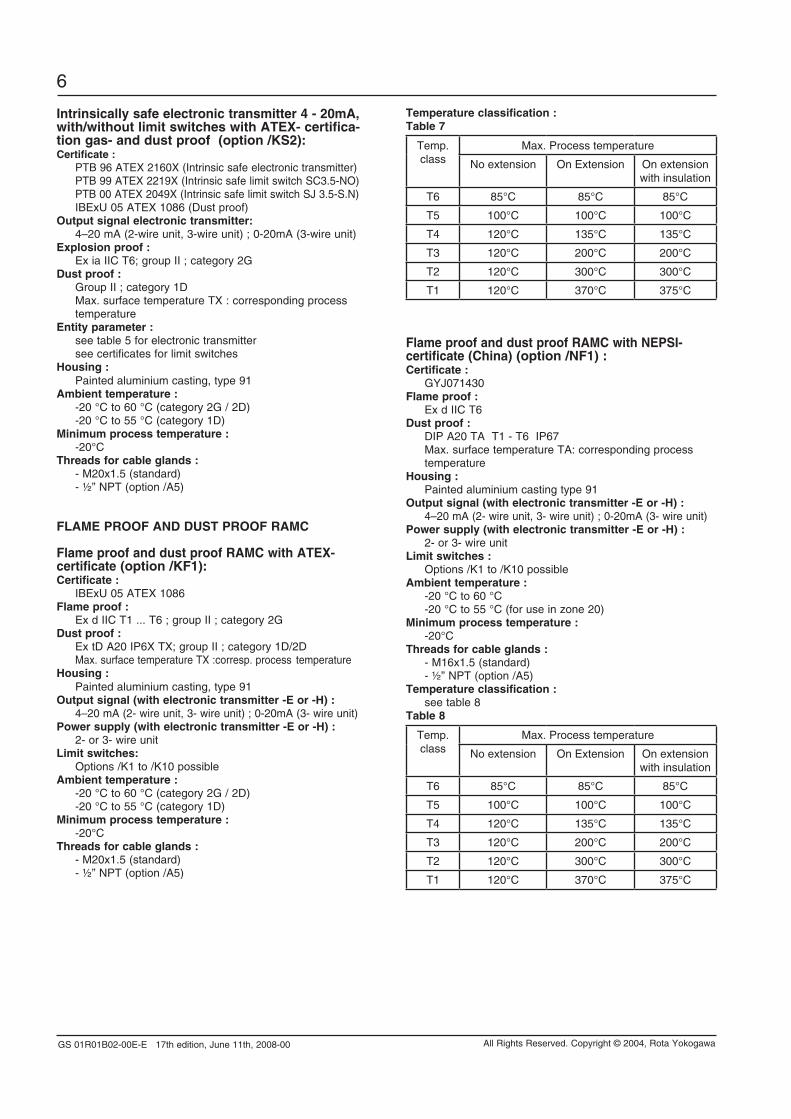
Temperature classification :Table 7
Temp. class
Max. Process temperature
No extension On Extension On extension with insulation
T6 85°C 85°C 85°C
T5 100°C 100°C 100°C
T4 120°C 135°C 135°C
T3 120°C 200°C 200°C
T2 120°C 300°C 300°C
T1 120°C 370°C 375°C
Flame proof and dust proof RAMC with nEpSi- certificate (China) (option /nF1) :Certificate : GYJ071430Flame proof : Ex d IIC T6 dust proof : DIP A20 TA T1 - T6 IP67 Max. surface temperature TA: corresponding process temperature Housing : Painted aluminium casting type 91output signal (with electronic transmitter -E or -H) : 4–20 mA (2- wire unit, 3- wire unit) ; 0-20mA (3- wire unit)power supply (with electronic transmitter -E or -H) : 2- or 3- wire unitLimit switches : Options /K1 to /K10 possibleAmbient temperature : -20 °C to 60 °C -20 °C to 55 °C (for use in zone 20)Minimum process temperature : -20°CThreads for cable glands : - M16x1.5 (standard) - ½” NPT (option /A5)Temperature classification : see table 8Table 8
Temp. class
Max. Process temperature
No extension On Extension On extension with insulation
T6 85°C 85°C 85°C
T5 100°C 100°C 100°C
T4 120°C 135°C 135°C
T3 120°C 200°C 200°C
T2 120°C 300°C 300°C
T1 120°C 370°C 375°C
intrinsically safe electronic transmitter 4 - 20mA, with/without limit switches with ATEX- certifica-tion gas- and dust proof (option /KS2):Certificate : PTB 96 ATEX 2160X (Intrinsic safe electronic transmitter) PTB 99 ATEX 2219X (Intrinsic safe limit switch SC3.5-NO) PTB 00 ATEX 2049X (Intrinsic safe limit switch SJ 3.5-S.N) IBExU 05 ATEX 1086 (Dust proof)output signal electronic transmitter: 4–20 mA (2-wire unit, 3-wire unit) ; 0-20mA (3-wire unit)Explosion proof : Ex ia IIC T6; group II ; category 2Gdust proof : Group II ; category 1D Max. surface temperature TX : corresponding process temperature Entity parameter : see table 5 for electronic transmitter see certificates for limit switches Housing : Painted aluminium casting, type 91Ambient temperature : -20 °C to 60 °C (category 2G / 2D) -20 °C to 55 °C (category 1D) Minimum process temperature : -20°CThreads for cable glands : - M20x1.5 (standard) - ½” NPT (option /A5)
FLAME pRooF And dUST pRooF RAMC
Flame proof and dust proof RAMC with ATEX- certificate (option /KF1):Certificate : IBExU 05 ATEX 1086 Flame proof : Ex d IIC T1 ... T6 ; group II ; category 2Gdust proof : Ex tD A20 IP6X TX; group II ; category 1D/2D Max. surface temperature TX :corresp. process temperature Housing : Painted aluminium casting, type 91output signal (with electronic transmitter -E or -H) : 4–20 mA (2- wire unit, 3- wire unit) ; 0-20mA (3- wire unit)power supply (with electronic transmitter -E or -H) : 2- or 3- wire unitLimit switches: Options /K1 to /K10 possibleAmbient temperature : -20 °C to 60 °C (category 2G / 2D) -20 °C to 55 °C (category 1D)Minimum process temperature : -20°CThreads for cable glands : - M20x1.5 (standard) - ½” NPT (option /A5)
GS 01R01B02-00E-E 17th edition, June 11th, 2008-00
7
All Rights Reserved. Copyright © 2004, Rota Yokogawa
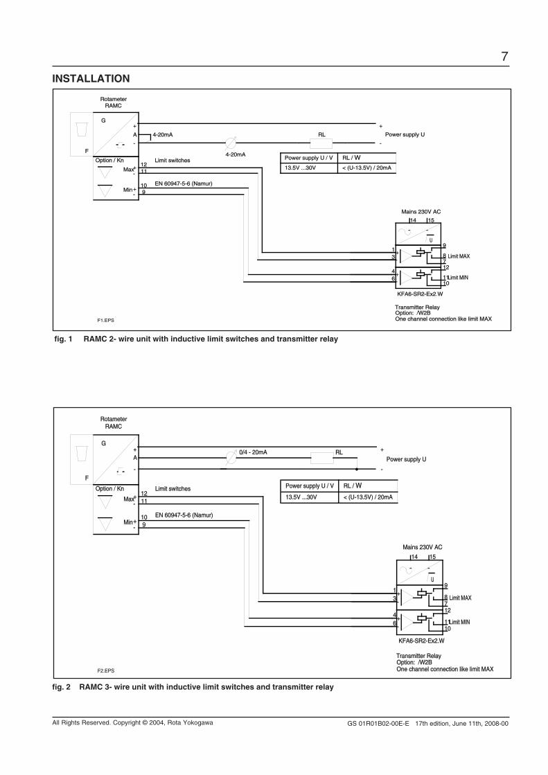
fig. 1 RAMC 2- wire unit with inductive limit switches and transmitter relay
15
46
31
14
12
1011
87
9U
F
G
RAMC
A Power supply U
Mains 230V AC
KFA6-SR2-Ex2.W
Option: /W2BTransmitter Relay
Limit MIN
Limit MAX
Option / Kn
Rotameter
4-20mA
Max
Min
1211
109
Limit switches
EN 60947-5-6 (Namur)
One channel connection like limit MAX
4-20mA
RL
-
+
-
+
-+
-+
~ ~
+-
+-
Power supply U / V RL / W
13.5V ...30V < (U-13.5V) / 20mA
F1.EPS
inSTALLATion
fig. 2 RAMC 3- wire unit with inductive limit switches and transmitter relay
15
46
31
14
12
1011
87
9U
F
G
RAMC
A Power supply U
Mains 230V AC
KFA6-SR2-Ex2.W
Option: /W2BTransmitter Relay
Limit MIN
Limit MAX
Option / Kn
Rotameter
Max
Min
1211
109
Limit switches
EN 60947-5-6 (Namur)
One channel connection like limit MAX
0/4 - 20mA RL
-
+
-
+
-+
-+
~ ~
+-
+-
Power supply U / V RL / W
13.5V ...30V < (U-13.5V) / 20mA
F2.EPS
GS 01R01B02-00E-E 17th edition, June 11th, 2008-00
8
All Rights Reserved. Copyright © 2004, Rota Yokogawa
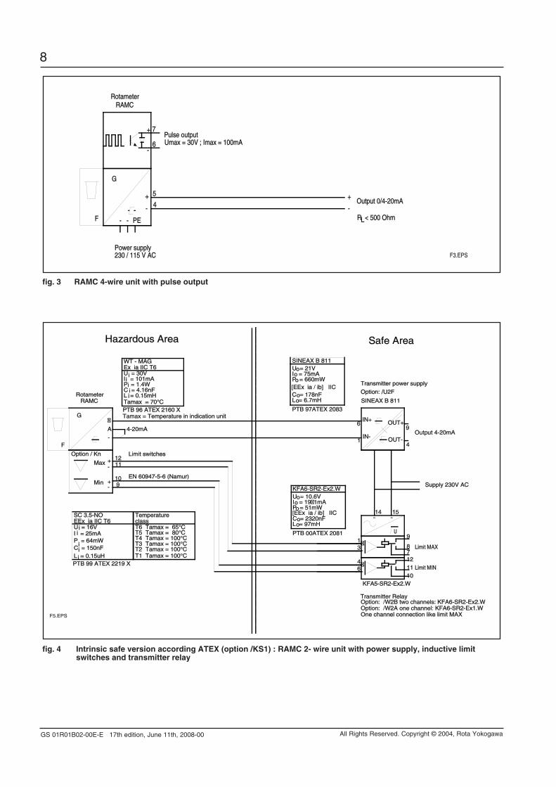
fig. 4 intrinsic safe version according ATEX (option /KS1) : RAMC 2- wire unit with power supply, inductive limit switches and transmitter relay
4
9
15
46
31
14
12
1011
87
9
1211
109
6
1
U
F
G
RAMC
AOutput 4-20mA
Supply 230V AC
KFA5-SR2-Ex2.W
Option: /W2B two channels: KFA6-SR2-Ex2.WTransmitter Relay
Limit MIN
Limit MAX
Option / Kn
Rotameter
4-20mA
Max
Min
Limit switches
EN 60947-5-6 (Namur)
One channel connection like limit MAX
I = 101mAP = 1.4WC = 4.16nF
U = 30V
L = 0.15mH
WT - MAGEx ia IIC T6
Tamax = 70°CPTB 96 ATEX 2160 XTamax = Temperature in indication unit
C = 150nF
EEx ia IIC T6
L = 0.15uH
SC 3.5-NO
P = 64mWI = 25mAU = 16V
Temperature
T4 Tamax = 100°CT3 Tamax = 100°CT2 Tamax = 100°CT1 Tamax = 100°C
class
T5 Tamax = 80°CT6 Tamax = 65°C
PTB 99 ATEX 2219 X
C = 178nF
I = 75mAP = 660mW
U = 21V
L = 6.7mH
PTB 97ATEX 2083
[EEx ia / ib] IIC
SINEAX B 811
Transmitter power supply
Option: /U2F
SINEAX B 811
Option: /W2A one channel: KFA6-SR2-Ex1.W
C = 2320nF
I = 191mAP = 51mW
U = 10.6V
L = 97mH
PTB 00ATEX 2081
[EEx ia / ib] IIC
KFA6-SR2-Ex2.W
-
-
-
~ ~
+-
+-
i
ii
i
ii
ii
o
o
o
oo
OUT-
OUT+IN+
IN-
o
o
o
oo
i
i
Hazardous Area Safe Area
F5.EPS
fig. 3 RAMC 4-wire unit with pulse output
F
G
RAMC
230 / 115 V AC
4
Power supply
Output 0/4-20mA
R < 500 OhmL
Rotameter
PE--
5
7
6Pulse outputUmax = 30V ; Imax = 100mA
-
+
-
+
+
-
F3.EPS
GS 01R01B02-00E-E 17th edition, June 11th, 2008-00
9
All Rights Reserved. Copyright © 2004, Rota Yokogawa
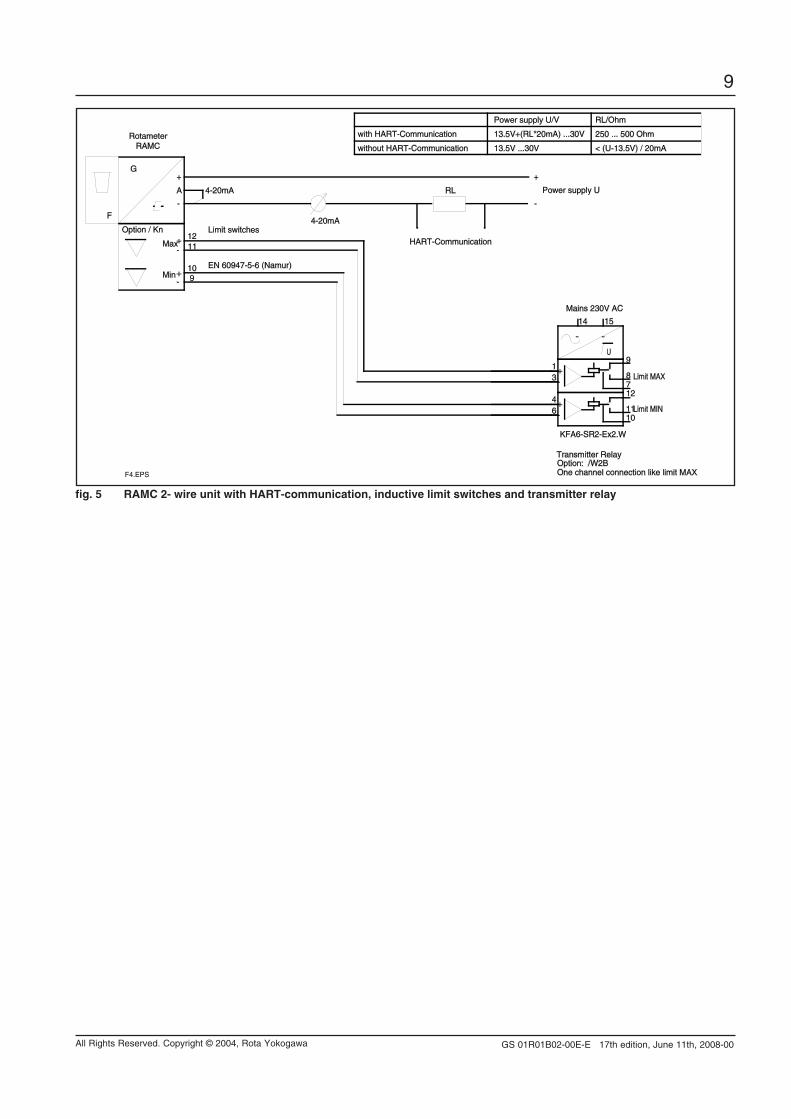
fig. 5 RAMC 2- wire unit with HART-communication, inductive limit switches and transmitter relay
15
46
31
14
12
1011
87
9U
F
G
RAMC
A Power supply U
Mains 230V AC
KFA6-SR2-Ex2.W
Option: /W2BTransmitter Relay
Limit MIN
Limit MAX
Option / Kn
Rotameter
4-20mA
Max
Min
1211
109
Limit switches
EN 60947-5-6 (Namur)
One channel connection like limit MAX
4-20mA
RL
HART-Communication
with HART-Communication
without HART-Communication
Power supply U/V RL/Ohm
13.5V+(RL*20mA) ...30V
13.5V ...30V < (U-13.5V) / 20mA
250 ... 500 Ohm
-
+
-
+
-+
-+
~ ~
+-
+-
F4.EPS
GS 01R01B02-00E-E 17th edition, June 11th, 2008-00
10
All Rights Reserved. Copyright © 2004, Rota Yokogawa
planning and installation Hints
- The user is responsible for the use of our flow meters regarding suitability and use as agreed.
- The actual operation pressure must be lower as the specified pressure limits of the Rotameter.
- Make sure that the wetted parts are resistant against the process medium.
- Ambient- and process temperature must be lower than the specified maximum values.
- If dirt accumulation is to be expected, we recommend to install a bypass pipe
- To avoid float bouncing in case of gas application notice the recommendations of VDI/VDE 3513 Sheet 3.
- To avoid mutual magnetic influence in case of parallel design of several Rotameters take care that the distance between the tube middle axes is not less than 300 mm. The distance to other ferric materials should not be less than 250 mm.
- Avoid static magnetic fields next to the Rotameter.
+–
+–
Field Instrument
Field Instrument
Safe Area
Hazardous Area
Terminator
Safety Barrier
F91.EPS
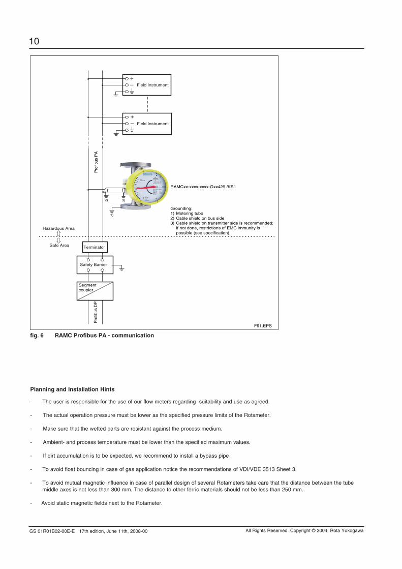
RAMCxx-xxxx-xxxx-Gxx429 /KS1
Pro
fibus
PA
Pro
fibus
DP
Segment coupler
Grounding:1) Metering tube2) Cable shield on bus side3) Cable shield on transmitter side is recommended; if not done, restrictions of EMC immunity is possible (see specification).
3)2)
1)
fig. 6 RAMC profibus pA - communication
GS 01R01B02-00E-E 17th edition, June 11th, 2008-00
11
All Rights Reserved. Copyright © 2004, Rota Yokogawa
ModEL SpECiFiCATionSModel Suffix code Option
code Description
RAMC01RAMC23RAMC02RAMC03RAMC04RAMC05RAMC06RAMC08
RAMC10RAMC12RAMC15
………………………………………………………………………………………………………………………………………………………………………………………………………………………………………………………………………………………
………………………………………
………………………………………
………………………………………………….......................................
…………
…………
……………………
………………
Size DN 15 ( ½ inch)Size DN 20 ( ¾ inch) Size DN 25 (1 inch) Size DN 32 (1 ¼ inch Size DN 40 (1 ½ inch Size DN 50 (2 inch) Size DN 65 (2 ½ inch) Size DN 80 (3 inch)
Size DN 100 (4 inch) Size DN 125 (5 inch)Size DN 150 (6 inch)
Processconnection
………….………...……
………….………...……
………….………...……
………….………...……
………….………...……
………….………...……
………….………...……
………….………...……………….………...……………….………...……………….………...……………….………...……………….………...……………….………...……………….………...……
.......
.......
.......
.......
.......
.......
.......
.......
.......
.......
.......
.......
.......
.......
.......
EN flange PN 16, process connection dimensions + facing acc. EN1092 - 1 Form B1EN flange PN 40, process connection dimensions + facing acc. EN1092 - 1 Form B1EN flange PN 63, process connection dimensions + facing acc. EN1092 - 1 Form B2EN flange PN 100, process connection dimensions + facing acc. EN1092 - 1 Form B2ASME flange class 150, process connection dimensions + facing acc. ASME B16.5 ASME flange class 300, process connection dimensions + facing acc. ASME B16.5 ASME flange class 600, process connection dimensions + facing acc. ASME B16.5 Thread female NPT - PN40Thread female G : PN40Thread female Rp : removableThread male DIN 11851Triclamp PN10 ; PN16Thread female NPT : removableFlanges Rosista PN10Without process connection
Material of wettedparts
SS …….……….….. PFNN
…………….…...
…………
Stainless steelTeflon liningWithout wetted parts
Cone / Float -nnnn …….........
-NNNN……........ ……
See tables 13 ... 15Without measuring tube / without float
Indicator / Transmitter T ………......E ……….....
H ..…….......N ……….......
…………
…………
Indicator local
Without indicator
Housing type 66 ………90 ………91 ………
………………
Housing rectangular yellow : Polyamide Housing round blank : SS Housing round yellow : Al
Power supply / Output 240 ....244 ....140 ....144 ....430 ....434 ....424 ....429 ....NNN ...
- -
- -
…………………………………….......……
230 V AC : 4-wire : 0-20 mA230 V AC : 4-wire : 4-20 mA115V AC : 4-wire : 0-20 mA115V AC : 4-wire : 4-20 mA24V DC : 3-wire : 0-20 mA 24V DC : 3-wire : 4-20 mA24V DC : 2-wire : 4-20 mAProfibus PA, 9 ... 32VDCWithout power supply
/[] T5.EPS
RAMC09 3 ½ inch
Indicator electronic HART
……………………………………… ……
See separate table on next page
RAMCNN …………....................................... …… Without measuring tube
…………….…... ……
……
NN ……… …… Without housing
Options
Indicator electronic
Restrictions
Only with housing NN
Not with indicator G
Only with indicator N
Only with indicator E. Not with limit switchesOnly with indicator E. Not with limit switches Only with indicator E. Not with limit switches Only with indicator E. Not with limit switchesOnly with indicator EOnly with indicator EOnly with indicator E or HOnly with indicator G. Not with limit switchesOnly with indicator T or N
for D4, D6, A1, A2, A3, T4, R4, T6, G6for D4, D6, A1, A2, A3, T4, R4, T6, G6for D4, D6, A1, A2, A3, S2, S4, S5, T4, R4, T6, G6for D4, D6, A1, A2, A3, S4, T6, G6for D4, D6, A1, A2, A3, S4, S5, T6, G6for D4, D5, D6, A1, A2, A3, S2, S4, T4, R4for D4, D5, A1, A2, A3, S2, S4, T4, R4, T6, G6for D4, D5, A1, A2, A3, S2, S4for A1, A2for D2, D4, A1, A2, S2, S4for D2, A1, A2, S2for D2, A1, A2
Only with RAMCNN
Only with RAMCNN
-D2
-D4
-D5
-D6
-A1
-A2
-A3
-T6-G6-R4-S2-S4-T4-S5-NN
- G ……….......
Indicator electronic with Profibus PA……Only with output 424Only with output 429
Specify the following when ordering :1) Model, suffix code and option code2) Fluid name ; Process temperature ; Process density ; Process pressure ; Process viscosity 3) For gases : Condition of the scale (st. or actual)4) Options : Tag No. ; Customer specific notes
GS 01R01B02-00E-E 17th edition, June 11th, 2008-00
12
All Rights Reserved. Copyright © 2004, Rota Yokogawa
opTionSOptions
Option code
Description
Indicator /A5/A8/A12/A13/A14/A16/A17/A18
Thread for cable gland ASME 1/2" NPT femaleWith scale for indicatorUS-engineering unitsThread for cable gland ISO M20 x 1.5 femaleHousing colour green Indicator on 95mm extension Housing colour greenHousing colour yellow
Marking
/B0/B1/BT1
/BT2/B4/B8/BG/BD
Tag plate (SS) on flange and marking on scale Tag plate (SS) fixed by wire and marking on scale Software Tag HART
Software Tag, Bus address for Profibus PANeutral versionCustomer provides marking on labelCustomer specific notes on scaleDual Scale
Restrictions
Not with option /A13Only without indicator; Not with Ex-proof typeOnly for indicator E + HNot with options /A5, /NF1Only for housing 66 + 91Only for housing 90 + 91Only for housing 90Only for housing 90Plate 9 x 40 mm; max. 45 digits Plate 9 x 40 mm; max. 45 digits 8 digits for Tag, only indicator -H22 digits for Long Tag, only indicator -H32 digits for Tag, 4 digits bus address, only -GNot with option /P6 and Ex-proof type
Max. 45 digitsAdjustment only for the first mentioned fluid
Limit switches /K1/K2/K3/K6/K7/K8/K9/K10
MIN-contactMAX-contactMIN-MAX-contact; MIN-MIN-contact; MAX-MAX-contactMIN-contact "Fail Safe"- versionMAX-contact "Fail Safe"- versionMIN-MAX-contact "Fail Safe"- versionMIN-MIN contact "Fail Safe"- versionMAX-MAX-contact "Fail Safe"- version
Pulse output /CP Pulse output, isolated
Facing (process connection)
/D10/D11
EN raised face B2 : Ra 0.8 - 3.2EN groove
Ex-proof type
/KS1
/KS2
/KF1
/KN1
/FS1
/SS1
/NS1
/NF1
ATEX intrinsically safe "ia"
ATEX intrinsically safe "ia" + dust proof
ATEX flame proof "d" / dust proof
ATEX category 3G "nL" / 3D
FM intrinsically safe approval for electronic transmitter,CSA intrinsically safe approval for limit switches(USA and Canada)SAA approval (Australia)
NEPSI intrinsically safe approval (China)
NEPSI flame proof "d" / dust proof approval (China)
Not for power supply 14n + 24nNot for power supply 14n + 24nNot for power supply 14n + 24nNot for power supply 14n + 24nNot for power supply 14n + 24nNot for power supply 14n + 24nNot for power supply 14n + 24nNot for power supply 14n + 24n
Only for power supply 14n + 24n
Only for EN-flanges (D2;D4)Only for EN-flanges (D2;D4)
Only for power supply 424, 430, 434, 429; for indicator T only with limit switchesNot for power supply 14n, 24n, 429; for indicator T only with limit switches;only for housing 91Not for power supply 14n, 24n, 429; for indicator T only with limit switches;only for housing 91Only for power supply 424, 430, 434; for indicator T only with limit switchesOnly for power supply 424;for indicator T only with limit switches
Only for power supply 424; for indicator T only with limit switches /K6 to /K10; only for housing 90Only for power supply 424, 430, 434; only for housing 90; for indicator T only with limit switchesNot for power supply 14n, 24n, 429; for indicator T only with limit switches;only for housing 91
Test and certificates
GOST approvals
/H1/H3/P2
/P3/P6
/PM3
/PP/PT/QR1/QR2
Oil + fat free for wetted surfaces acc.ASTM G93-03,lev. CCertificate pure water applicationCertificate of Compliance with the order acc. to EN 10204: 2004- 2.1As /P2 +Test report acc. to EN 10204: 2004- 2.2 Material certificate acc. to EN 10204: 2004- 3.1
PAMI test (3 test points: process connection inlet, metering tube, process connection outlet)Pressure test report measuring systemFlowtable for conversionRussian GOST approvalKasachian GOST approval
Only for metallic pressurized parts;not for process connection R4 + T4Only for SS material of wetted parts
Damping /SD Float damping system
Heat tracing
/T1/T2/T3/T4/T5/T6
Heat tracing, process connection R 1/4"Heat tracing, process connection DN15 PN40Heat tracing, process connection DN25 PN40Heat tracing, process connection ASME 1/2" 150#Heat tracing, process connection ASME 1" 150#Heat tracing, process connection 1/4" NPT female thread
Power supply forelectronic transmitter
/U2F /U3F
SINEAX B811, 85 - 250 V AC, EEx i SINEAX B811, 24 V AC/DC, EEx i
Power supply forlimit switch(es)(transmitter relay)
/W1A/W1B/W2A/W2B/W2E/W4A/W4B/W4E
T6.EPS
Only for stainless steel; not for cone 81 + 82; only for gas application
Only for SS material of wetted partsOnly for SS material of wetted partsOnly for SS material of wetted partsOnly for SS material of wetted partsOnly for SS material of wetted partsOnly for SS material of wetted parts
Only for indicator E + HOnly for indicator E + H
Only for limit switches /K1 + /K2 + /K3Only for limit switches /K1 + /K2 + /K3Only for limit switches /K1 + /K2 + /K3Only for limit switches /K1 + /K2 + /K3Only for limit switches /K6 to /K10Only for limit switches /K1 + /K2 + /K3Only for limit switches /K1 + /K2 + /K3Only for limit switches /K6 to /K10
KFA5-SR2-Ex1.W / 115 V AC, 1 channelKFA5-SR2-Ex2.W / 115 V AC, 2 channelsKFA6-SR2-Ex1.W / 230 V AC, 1 channelKFA6-SR2-Ex2.W / 230 V AC, 2 channelsKHA6-SH-Ex1 / 230 V AC, 1 channel, Fail SafeKFD2-SR2-Ex1.W / 24 V DC, 1 channelKFD2-SR2-Ex2.W / 24 V DC, 2 channelsKFD2-SH-Ex1 / 24 V DC, 1 channel, Fail Safe
Flange protection
Instruction manuals /IEn/IDn/IFn
Quantity of instruction manuals in English Quantity of instruction manuals in German Quantity of instruction manuals in French
n = 1 to 9 selectable *)n = 1 to 9 selectable *)n = 1 to 9 selectable *)*) if no instruction manual is selected, only a CD with instruction manuals is shipped with the flowmeter
Only for flange EN
/U2K/U3K
Only for indicator E + HOnly for indicator E + H
SINEAX B811, 85 - 250 V AC, EEx i, HART compatibleSINEAX B811, 24 V AC/DC, EEx i , HART compatible
Flange covers (flange EN) /QK
GS 01R01B02-00E-E 17th edition, June 11th, 2008-00
13
All Rights Reserved. Copyright © 2004, Rota Yokogawa
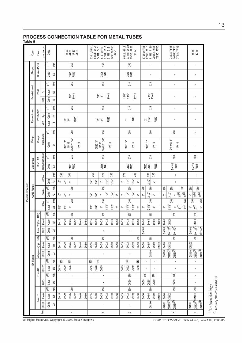
pRoCESS ConnECTion TAbLE FoR METAL TUbESTable 9
Con
e
F
loat
PN16
PN40
PN63
PN10
0PN
16PN
40PN
16PN
40NP
TRp
NPT
Gco
mbina
tion
Code
Code
L(1)
Code
L(1)
Code
L(1)
Code
Code
L(1)
Code
Code
L(1)
Code
L(1)
Code
L(1)
Code
L(1)
Code
L(1)
Code
L(1)
Code
Code
L(1)
Code
Code
L(1)
Code
L(1)
Code
D2D4
mmD5
mmD6
mmD2
D4mm
D2D4
mmA1
mmA2
mmA3
mmS2
mmS4
mmT4
R4mm
T6G6
mmS5
mm
DN15
DN15
DN15
DN15
1/2"
1/2"
1/2"
DN20
DN20
DN20
DN20
3/4"
3/4"
3/4"
DN25
DN25
260
DN25
DN25
1"1"
1"26
0
DN32
DN32
DN32
DN40
DN40
DN40
DN50
DN50
DN50
DN15
DN15
250
DN15
DN15
1/2"
1/2"
1/2"
DN20
DN20
DN20
DN20
3/4"
3/4"
3/4"
DN25
DN25
DN25
DN25
1"1"
1"
DN32
DN32
DN32
1 1/4"
1 1/4"
1 1/4"
DN40
DN40
DN40
1 1/2"
1 1/2"
1 1/2"
280
DN50
DN50
DN50
2"2"
DN25
DN25
DN25
DN25
1"1"
1"
DN32
DN32
DN32
DN32
1 1/4"
1 1/4"
1 1/4"
DN40
DN40
DN40
DN40
1 1/2"
1 1/2"
1 1/2"
DN50
DN50
280
DN50
DN50
2"2"
2"
DN50
DN50
DN50
DN10
0DN
502"
2"25
0
DN65
DN65
DN65
DN65
2 1/2"
2 1/2"
2 1/2"
280
DN80
DN80
270
__
DN80
DN80
3"3"
3"29
0
DN10
0DN
100
DN10
0
DN10
0DN
80DN
100
DN80
DN10
0DN
803"
3"26
0
DN12
5(2) DN
100
DN12
5(2) DN
100
DN12
5(2) DN
100
3 1/2"
3 1/2"
DN15
0(2)
DN15
0(2)
DN15
0(2)
4"4"
5"(2
)5"
(2)
6"(2
)26
06"
(2)
DN10
0DN
100
DN10
0DN
100
4"4"
260
DN12
5(2)
DN12
5(2)
DN12
5(2)
5"(2
)5"
(2)
__
DN15
0(2)
DN15
0(2)
DN15
0(2)
6"26
06"
(2)
DN25
PN10
DN25
PN10
DN40
PN10
2 1/2"
PN40
1/2"
PN40
3/4"
1" PN40
1 1/4"
1 1/2"
PN40
-
250
-
250
-
270
DN50
-
250
260
260
--
250
250
250
250
325
1" PN16
-
- --
250
310
--
- -
--
310
-
DN10
0
250
270
-
250
300
-
250
--
250
_
- -
DN10
0
- -25
0
250
_
250
270
250
280
260
280
325
-
2" 2 1/2"
PN10
250
_30
0_
DN10
0PN
25
250
270
280
275
300
250
295
295
275
250
-25
0
_
250
250
250
EN-F
lange wi
th gr
oove
(Opt.
: D11
)
250
250
--
Form
B2 (
Opt.:
D10)
-
250
PN16
/PN2
5/PN4
0
Calm
p
Clam
p
PN10
/PN1
6
Male
threa
d
DIN1
1851
250
250
ASME
-Flan
geFla
nge
Rosis
ta PN
10 P
N10-
PN25
PN40
Pro
cess
conn
ectio
n
1 2
Form
B1
Form
B2
150lb
s30
0lbs
600lb
sPo
s
Fema
le thr
ead
270 -
3 4 5 6
260
270
67 L5
; 67 M
567
S5 ;
71 L5
71 M
5 ; 71
S5
72 L5
; 72 M
572
S5 ;
72V5
73 L8
; 73 V
874
L8 ; 7
4 V8
77 L8
; 77 V
8
81 11
82 11
DN10
0
DN80
_ -
250
250
-
53 L1
; 53 M
153
S1 ;
54 L1
54 M
1 ; 54
S1
57 L1
; 57 M
157
S1 ;
61 L1
61 M
1 ; 61
S1
62 L1
; 62 M
162
V1
63 L2
; 64 L
263
M2 ;
64 M
263
S2 ;
64 S
264
V2
43 S
044
S0
47 S
051
S0
250
250
250
1/2"
3/4"
PN25
1/2"
3/4"
PN25
295
295
DN12
5PN
16
DN25
PN40
DN25
PN40
DN50
PN25
DN65
DN80
PN25
DN25
/ 1"
DN32
DN40
/ 1 1/
2"
PN16
DN10
0
DN10
0 / 4"
PN10
DN65
/ 3"
PN10
DN50
/ 2"
PN16
DN25
/ 1"
DN32
DN40
/ 1 1/
2"
PN16
275
250
250
275
(1)
L
= fac
e to f
ace l
ength
(2)
A
ccur
acy
class
2,5
inst
ead
1,6
Fema
le thr
ead
GS 01R01B02-00E-E 17th edition, June 11th, 2008-00
14
All Rights Reserved. Copyright © 2004, Rota Yokogawa
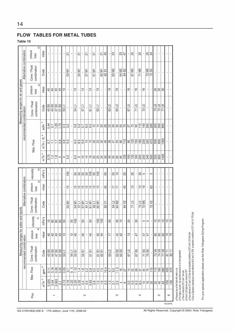
FLoW TAbLES FoR METAL TUbESTable 10
Mea
surin
g ra
nges
for w
ater
and
liqu
ids
Mea
surin
g ra
nges
for a
ir an
d ga
ses
re
com
men
ded
com
bina
tion
Alte
rnat
ive
com
bina
tion
reco
mm
ende
d co
mbi
natio
n A
ltern
ativ
e co
mbi
natio
n
Max
. Flo
w
C
one
/ Flo
at
com
bina
tion
lo
ss
pr
essu
re
a)
vi
scos
ity - b)
a
) b)
M
ax. F
low
a)
a
) P
os.
m3 /h
c)
gpm
d)
Cod
e
mba
r m
Pa*
s C
ode
mba
r m
Pa*
s
m3 /h
c)
m3 /h
i. N
. e)
scfm
f)
Cod
e
mba
r C
ode
mba
r
0.02
5 0.
11
43 S
0 40
10
-
- -
0.
75
0.7
0.44
43
S0
45
- -
0.04
0.
18
44 S
0 40
80
-
- -
1.
2 1.
1 0.
7 44
S0
45
- -
0.06
3 0.
28
47 S
0 40
80
-
- -
1.
8 1.
7 1,
05
47 S
0 45
-
- 1
0.1
0.45
51
S0
40
80
- -
-
3 2.
8 1.
75
51 S
0 45
-
-
0.13
0.
55
53 L
1 12
50
-
- -
4 3.
6 2.
3 53
L1
13
- -
0.16
0.
7 -
- -
53 M
1 15
10
0
5.5
5.0
3.2
- -
53 M
1 21
0.
22
0.5
54 L
1 12
50
-
- -
-
- -
- -
- -
0.25
1.
12
53 S
1 40
10
0 54
M1
15
50
6.
5 6.
0 3.
8 54
L1
13
- -
0.32
1.
4 -
- -
57 L
1 12
50
9 8.
5 5.
0 -
- 54
M1
21
0.4
1.8
54 S
1 40
50
57
M1
15
50
10
9.
0 5.
7 57
L1
13
- -
0.5
2.2
- -
- 61
L1
12
50
14
13
8.
0 -
- 57
M1
21
0.63
2.
8 57
S1
40
50
61 M
1 15
10
0
16
15
9.0
61 L
1 13
-
- 0.
8 3.
5 -
- -
62 L
1 12
50
22
20
12
- -
61 M
1 21
1.
0 4.
5 61
S1
40
100
62 M
1 15
10
0
25
23
14
62 L
1 13
-
- 1.
6 7.
0 62
S1
40
100
- -
-
34
32
20
- -
62 M
1 21
2
2.3
10.4
-
- -
62 V
1 45
50
50
45
28
- -
62 S
1 45
1.3
5.7
63 L
2 17
50
-
- -
40
36
23
63
L2
19
- -
2.1
9.2
- -
- 64
L2
17
50
50
47
29
-
- 63
M2
23
2.5
11.2
63
S2
42
30
64 M
2 17
10
60
55
35
64 L
2 19
-
- 4
18
64 S
2 42
10
-
- -
85
80
50
-
- 64
M2
23
3
6 27
-
- -
64 V
2 43
20
120
110
70
- -
64 S
2 47
3,2
14
67 L
5 13
20
10
0 90
57
67
L5
16
- -
5,0
22
- -
- 71
L5
13
30
13
0 12
0 75
-
- 67
M5
25
6,3
28
67 S
5 47
30
-
- -
16
0 15
0 90
71
L5
16
- -
8,5
37
- -
- 72
L5
13
30
20
0 18
0 11
5 -
- 71
M5
25
10
45
71 S
5 47
5
72 M
5 19
5
25
0 23
0 14
0 72
L5
16
- -
16
70
72 S
5 47
5
- -
-
340
320
200
- -
72 M
5 25
4
25
110
- -
- 72
V5
63
5
500
470
290
- -
72 S
5 54
25
110
73 V
8 60
10
-
- -
55
0 50
0 32
0 73
L8
30
- -
40
180
74 V
8 60
10
-
- -
85
0 80
0 50
0 74
L8
30
- -
5 63
28
0 77
V8
60
10
- -
-
1400
13
00
800
77 L
8 30
-
-
100
450
81 1
1 70
10
-
- -
-
- -
- -
- -
6 13
0 57
0 82
11
70
10
- -
-
- -
- -
- -
-
T8.EPS
Con
e / F
loat
com
bina
tion
loss
pres
sure
vi
scos
itylo
sspr
essu
re
loss
pres
sure
C
one
/ Flo
atco
mbi
natio
nC
one
/ Flo
atco
mbi
natio
n
a) P
ressu
re los
s at th
e floa
t with
wate
r or a
ir. b)
For h
igher
visco
sity
the sp
ecifie
d prec
ision
is no
more
garan
teed.
c) Fl
ow is
refer
red to
20°C
and 1
bar a
bs d)
Flow
in U
S Ga
lonen
per m
inute
at 70
°F e)
Flow
refer
red to
0°C
and 1
.013 b
ar ab
s at o
perat
ion co
nditio
ns of
20°C
and 1
,013 b
ar ab
s f)
Flow
in St
anda
rd cu
bicfee
t per
minu
te ref
erred
to 60
°F an
d 14,7
PSI a
t ope
ration
cond
itions
of 70
°F un
d 14,7
PSI
abs
For y
our s
peci
al a
pplic
atio
n pl
ease
use
the
Rot
a Y
okog
awa
Siz
ing-
Pro
gram
GS 01R01B02-00E-E 17th edition, June 11th, 2008-00
15
All Rights Reserved. Copyright © 2004, Rota Yokogawa
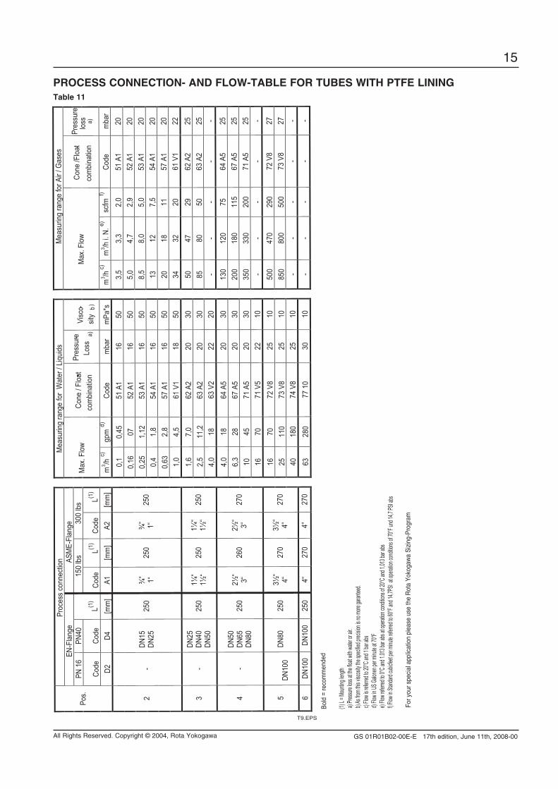
pRoCESS ConnECTion- And FLoW-TAbLE FoR TUbES WiTH pTFE LininGTable 11
Proc
ess
conn
ectio
n
M
easu
ring
rang
e fo
r W
ater
/ Li
quid
s
M
easu
ring
rang
e fo
r Air
/ Gas
esEN
-Fla
nge
AS
ME-
Flan
ge
PN
16
PN40
15
0 lb
s 30
0 lb
s
Code
Co
de
L(1)
Code
L(1
) Co
de
L(1)
Max
. Flo
w
Co
ne /
Floa
t- co
mbi
natio
n
Pres
sure-
Loss
a)
Vi
sco-
sity
b)
M
ax. F
low
Co
ne /F
loat-
com
bina
tion
Pres
sure
loss a)
Po
s.
D2
D4
[mm
] A1
[m
m]
A2
[mm
]
m3 /h
c)
gpm
d)
Code
m
bar
mPa
*s
m
3 /h c)
m
3 /h i.
N. e
) sc
fm f)
Co
de
mba
r
0,1
0,45
51
A1
16
50
3,
5 3,
3 2,
0 51
A1
20
0,16
07
52
A1
16
50
5,
0 4,
7 2,
9 52
A1
20
0,25
1,
12
53 A
1 16
50
8,5
8,0
5,0
53 A
1 20
0,
4 1,
8 54
A1
16
50
13
12
7,
5 54
A1
20
0,63
2,
8 57
A1
16
50
20
18
11
57
A1
20
2 -
DN15
DN
25
250
¾“ 1“
250
¾“ 1“
250
1,
0 4,
5 61
V1
18
50
34
32
20
61
V1
22
1,6
7,0
62 A
2 20
30
50
47
29
62 A
2 25
2,
5 11
,2
63 A
2 20
30
85
80
50
63 A
2 25
3
- DN
25
DN40
DN
50
250
1¼“
1½“
250
1¼“
1½“
250
4,
0 18
63
V2
22
20
-
- -
- -
4,0
18
64 A
5 20
30
130
120
75
64 A
5 25
6,
3 28
67
A5
20
30
20
0 18
0 11
5 67
A5
25
10
45
71 A
5 20
30
350
330
200
71 A
5 25
4
- DN
50
DN65
DN
80
250
2½“
3“
260
2½“
3“
270
16
70
71
V5
22
10
-
- -
- -
16
70
72 V
8 25
10
500
470
290
72 V
8 27
25
11
0 73
V8
25
10
85
0 80
0 50
0 73
V8
27
5 DN
100
DN80
25
0 3½
“ 4“
27
0 3½
“ 4“
27
0
40
180
74 V
8 25
10
- -
- -
-
6 DN
100
DN10
0 25
0 4“
27
0 4“
27
0
63
280
77 1
0 30
10
- -
- -
-
(1) L =
Mount
ing len
gt h a)
Pres s
ure los
s at th
e float
with w
ater o
r ai r.
b) As
from t
his vis
cosity
the sp
ecified
preci
si on is
no mo
re gar
anteed
. c)
Flow i
s refer
red to
20°C a
nd 1 b
ar abs
d) Flo
w in U
S Galo
nen pe
r minu
te at 70
°F e)
Flow r
eferre
d to 0°
C and
1.013
bar ab
s at op
eration
condi
tions o
f 20°C
and 1
,013 b
ar abs
f) Flo
w in S
tandar
d cubi
cfeet p
er min
ute re
fe rred
to 60°
F and
14,7P
SI at
operat
ion co
ndition
s of 70
°F und
14,7 P
SI abs
T9.EPS
For y
our s
peci
al a
pplic
atio
n pl
ease
use
the
Rot
a Yo
koga
wa
Sizi
ng-P
rogr
am
Bold
= re
com
men
ded
GS 01R01B02-00E-E 17th edition, June 11th, 2008-00
16
All Rights Reserved. Copyright © 2004, Rota Yokogawa
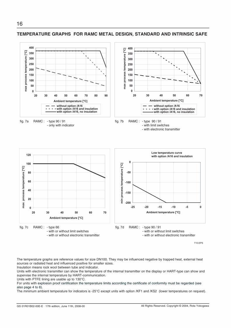
TEMpERATURE GRApHS FoR RAMC METAL dESiGn, STAndARd And inTRinSiC SAFE
The temperature graphs are reference values for size DN100. They may be influenced negative by trapped heat, external heat sources or radiated heat and influenced positive for smaller sizes.Insulation means rock wool between tube and indicator.Units with electronic transmitter can show the temperature of the internal transmitter on the display or HART-type can show and supervise the internal temperature by HART-communication.Units with PTFE lining are usable up to 130°C.For units with explosion proof certification the temperature limits according the certificate of conformity must be regarded (see also page 4 to 6).The minimum ambient temperature for indicators is -25°C except units with option /KF1 and /KS2 (lower temperatures on request).
T10.EPS
0
50
100
150
200
250
300
350
400
20 30 40 50 60 70 80 90
Ambient temperature [°C]
max
pro
cess
tem
pera
ture
[°C
]
without option /A16with option /A16 and insulationwith option /A16, no insulation
050
100
150200250300
350400
20 30 40 50 60 70
Ambient temperature [°C]
max
pro
cess
tem
pera
ture
[°C
]
without option /A16with option /A16 and insulationwith option /A16, no insulation
-200
-150
-100
-50
0
-25 -20 -15 -10 -5 0
Ambient temperature [°C]
min
pro
cess
tem
pera
ture
[°C
]
Low temperature curvewith option /A16 and insulation
0
20
40
60
80
100
120
20 30 40 50 60 70
Ambient temperature [°C]
max
. pro
cess
tem
pera
ture
[°C
]
fig. 7a RAMC : - type 90 / 91 - only with indicator
fig. 7b RAMC : - type 90 / 91 - with limit switches - with electronic transmitter
fig. 7d RAMC : - type 90 / 91 - with or without limit switches - with or without electronic transmitter
fig. 7c RAMC : - type 66 - with or without limit switches - with or without electronic transmitter
GS 01R01B02-00E-E 17th edition, June 11th, 2008-00
17
All Rights Reserved. Copyright © 2004, Rota Yokogawa
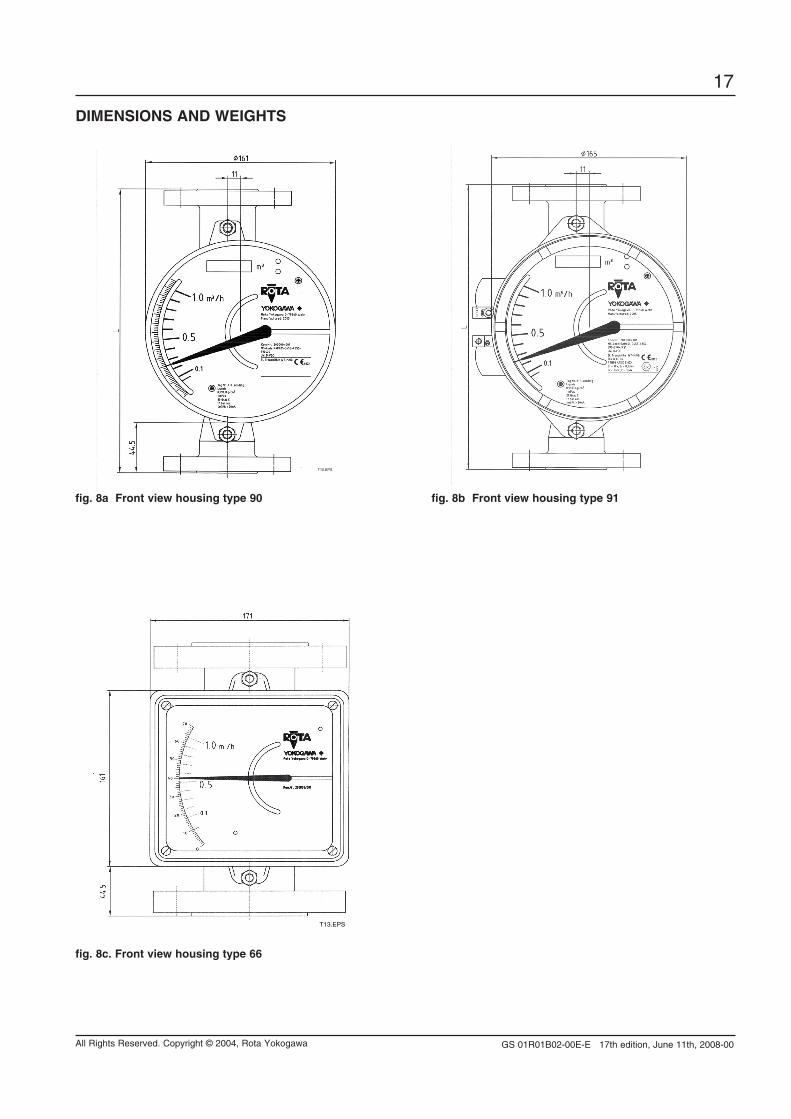
diMEnSionS And WEiGHTS
fig. 8a Front view housing type 90 fig. 8b Front view housing type 91
T12.EPS
fig. 8c. Front view housing type 66
T13.EPS
GS 01R01B02-00E-E 17th edition, June 11th, 2008-00
18
All Rights Reserved. Copyright © 2004, Rota Yokogawa
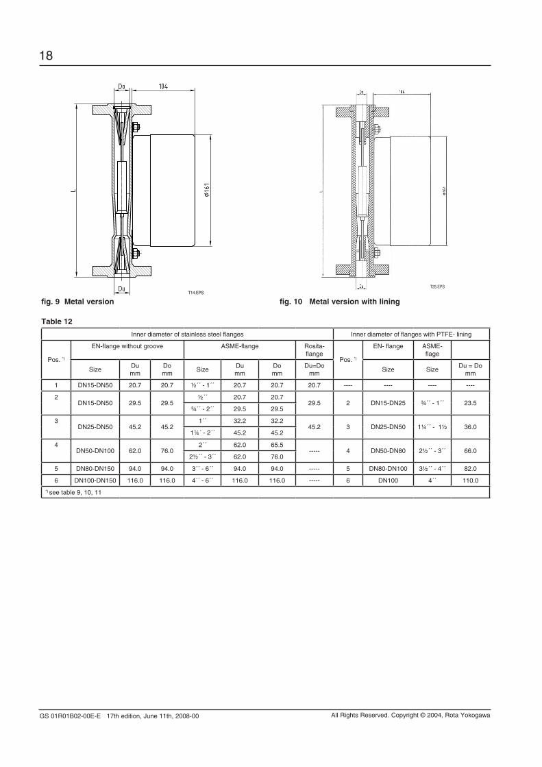
fig. 9 Metal version fig. 10 Metal version with liningT14.EPS
T25.EPS
Table 12
Inner diameter of stainless steel flanges Inner diameter of flanges with PTFE- lining
Pos. *)
EN-flange without groove ASME-flange Rosita- flange
Pos. *)
EN- flange ASME-flage
SizeDumm
Domm
SizeDumm
Domm
Du=Domm
Size SizeDu = Do
mm
1 DN15-DN50 20.7 20.7 ½´´ - 1´´ 20.7 20.7 20.7 ---- ---- ---- ----
2DN15-DN50 29.5 29.5
½´´ 20.7 20.729.5 2 DN15-DN25 ¾´´ - 1´´ 23.5
¾´´ - 2´´ 29.5 29.5
3DN25-DN50 45.2 45.2
1´´ 32.2 32.245.2 3 DN25-DN50 1¼´´ - 1½ 36.0
1¼´ - 2´´ 45.2 45.2
4DN50-DN100 62.0 76.0
2´´ 62.0 65.5----- 4 DN50-DN80 2½´´ - 3´´ 66.0
2½´´ - 3´´ 62.0 76.0
5 DN80-DN150 94.0 94.0 3´´ - 6´´ 94.0 94.0 ----- 5 DN80-DN100 3½´´ - 4´´ 82.0
6 DN100-DN150 116.0 116.0 4´´ - 6´´ 116.0 116.0 ----- 6 DN100 4´´ 110.0
*) see table 9, 10, 11
GS 01R01B02-00E-E 17th edition, June 11th, 2008-00
19
All Rights Reserved. Copyright © 2004, Rota Yokogawa
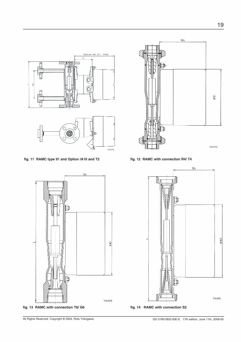
fig. 11 RAMC type 91 and option /A16 and T2 fig. 12 RAMC with connection R4/ T4
fig. 13 RAMC with connection T6/ G6 fig. 14 RAMC with connection S2
T25.EPS
T19.EPST18.EPS
T26.EPS
GS 01R01B02-00E-E 17th edition, June 11th, 2008-00
20
All Rights Reserved. Copyright © 2004, Rota Yokogawa
Manufactured by:ROTA YOKOGAWARheinstr. 8D-79664 WehrGermany
RotameterTM is a trademark of Rota Yokogawa GmbH & Co. KG, a subsidiary of Yokogawa Electric Corporation, Japan. In the United Kingdom RotameterTM is a trademark of Emerson Electric Co.
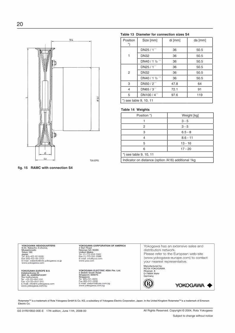
Table 13 diameter for connection sizes S4
Position *)
Size [mm] di [mm] da [mm]
1
DN25 / 1´´ 36 50.5
DN32 36 50.5
DN40 / 1 ½ ´´ 36 50.5
2
DN25 / 1´´ 36 50.5
DN32 36 50.5
DN40 / 1 ½ ´´ 36 50.5
3 DN50 / 2´´ 47.8 64
4 DN65 / 3´´ 72.1 91
5 DN100 / 4´´ 97.6 119
*) see table 9, 10, 11
Table 14 Weights
Position *) Weight [kg]
1 3 - 5
2 3 - 5
3 6.5 - 8
4 8.6 - 11
5 13 - 16
6 17 - 20
*) see table 9, 10, 11
Indicator on distance (option /A16) additional 1kgT20.EPS
fig. 15 RAMC with connection S4
Subject to change without notice