General Maintenance Guide 120-38371 - Gentec - … Control Panel K4 - Installation Guide 38371- C...
22
Lighting Control Panel K4 - Installation Guide 38371-C Eng.doc Page 1 of 22 General Installation Instructions Maintenance Guide 120-38371 SPECIFICATIONS Supply Voltages ........................................................................................per selected power supply Power Supply........................................................................................ 120, 208, 277, 347, 480VAC Accessory Power Output .............................................................................. 800mA @ 24VDC/VAC HID Relay Load Ratings @ 120VAC @ 277VAC @ 347VAC @ 480VAC UL Listing - CSA Certifications 20A 347VAC 2400W 120VAC "T" 20A 300VAC "F" 20A 480VAC "F" (2 poles relay 480v only) UL Endurance Test 150,000 cycles Output SPST 1P or 2P Contact Ratings More than 30,000 operations with 20A load, 2000A inrush @ 20 times/min switch speed Environmental Maximum Ambient Temperature ...................................... 20°F to +120°F (-28°C to +50°C) Maximum Humidity ............................................................ 5% to 90% RH, non-condensing Type/Nema .............................................................................. 1 or on request 12, 4 and 4X Printed in Canada
Transcript of General Maintenance Guide 120-38371 - Gentec - … Control Panel K4 - Installation Guide 38371- C...

Lighting Control Panel
K4 - Installation Guide 38371-C Eng.doc
Page 1 of 22
General Installation
Instructions Maintenance
Guide
120-38371 SPECIFICATIONS Supply Voltages ........................................................................................ per selected power supply Power Supply ........................................................................................ 120, 208, 277, 347, 480VAC Accessory Power Output .............................................................................. 800mA @ 24VDC/VAC HID Relay Load Ratings @ 120VAC @ 277VAC @ 347VAC @ 480VAC UL Listing - CSA Certifications 20A 347VAC 2400W 120VAC "T" 20A 300VAC "F" 20A 480VAC "F" (2 poles relay 480v only) UL Endurance Test 150,000 cycles Output SPST 1P or 2P Contact Ratings More than 30,000 operations with 20A load, 2000A inrush @ 20 times/min switch speed Environmental Maximum Ambient Temperature ...................................... 20°F to +120°F (-28°C to +50°C) Maximum Humidity ............................................................ 5% to 90% RH, non-condensing Type/Nema .............................................................................. 1 or on request 12, 4 and 4X
Prin
ted
in C
anad
a

Lighting Control Panel
K4 - Installation Guide 38371-C Eng.doc
Page 2 of 22
DOCUMENT’S HISTORY
Review Date Description Authors Release July 2009 Installation Guide writing Marcel Landry
A September 2009 General Revision DCI-116 Marcel Landry
B October 2012 Page number correction Natasha Brousseau
C April 2012 Adapted to the KC600/remove all references to WR-6161k-84 relay
Jean-Michel Tremblay
DOCUMENT’S APPROBATION
Verification: Jean-Michel Tremblay
Reviewed and Approved: Marcel Landry Reviewed and Approved: Mario Lehoux

Lighting Control Panel
K4 - Installation Guide 38371-C Eng.doc
Page 3 of 22
READ THOROUGHLY BEFORE INSTALLING Make all electrical connections in accordance with the National and Canadian Electrical Code and any applicable local code requirements. Verify that supply voltage is correct by comparing it to nameplate. Before installing the Lighting Control Panel, read the instructions completely. If you have any questions, call our Service Team at: in Canada 800-463-4480; in USA 888-235-7506.
WARNING: Danger of electrical shock or injury. Turn OFF power service to the line side of the Panel board or switchboard before working inside the equipment or removing any component. Equip-ment is to be installed and maintained by properly trained and qualified personnel only.
Important Installation Notices
• All power must be turned off prior to wiring, installing or servicing.
• More than one disconnect may be required to de-energize power to the Lighting Control Panel.
• External circuit protection to the LI is required (e.g., circuit breaker).
• Installation shall be in accordance with all applicable regulations, wiring practices, and
codes.
• Care should be taken to separate high voltage power from low voltage (Class 2) control wiring.
• Do not energize wiring until the unit is fully assembled and connected circuits have been
tested and found to be free of electrical shorts.
WARNING Improper installation or connection of this
relay panel may result in serious personal injury and/or damage to the panel and other devices

Lighting Control Panel
K4 - Installation Guide 38371-C Eng.doc
Page 4 of 22
SAFETY PRECAUTIONS
▪ Only qualified persons familiar with the construction and operation of this equipment should perform work described in this set of instructions. Such work should be performed only after reading this complete set of instructions.
▪ Follow safety related work practices, as described in NFPA 70E at all times.
▪ Hazardous voltages in electrical equipment can cause severe personal injury or death.
Energizing this equipment for the first time after initial installation or maintenance is potentially dangerous. Inspection and maintenance should be performed on this equip-ment power has been cut off, disconnected, and electrically isolated so that no accidental contact can be made with energized parts.
▪ Some types of electrical equipments will cause harmonics in the electrical system which
may result in overheating. Consider this condition when determining this equipment load-ing, as possible de-rating of equipment may be necessary.
IMPORTANT The information contained herein is general in nature and not intended for specific application purposes. It does not relieve the user of responsibility to use sound practices in application, installation, operation, and maintenance of the equipment purchased. Gentec Inc. reserves the right to make changes in the specifications shown herein or to make improvements at any time without notice or obligations. Should a conflict arise between the general information contained in this publication and the contents of drawings or supplementary material or both, the latter shall take precedence.
Qualified Person For the purpose of this manual and product labels, a qualified person is one who is familiar with the installation, construction, operation or maintenance of the equipment and the hazards involved. In addition, this person has the following qualifications:
(a) Is trained and authorized to de-energize, clear, ground, and tag circuits and equipment in accordance with established safety practices.
(b) Is trained in the correct care and use of protective equipment such as rubber gloves, hard
hat, safety glasses or face shields, flash clothing etc., in accordance with established safety practices.

Lighting Control Panel
K4 - Installation Guide 38371-C Eng.doc
Page 5 of 22
SIGNAL WORDS The signal words “Danger”, “Warning” and “Caution” used in this manual indicate the degree of hazard that may be encountered by the user. These words are defined as:
Danger – Indicates an imminently hazardous situation which if not avoided, will result
in death or serious injury.
Warning – Indicates a potentially hazardous situation which, if not avoided, could result
in death or serious injury.
Caution – Indicates a potentially hazardous situation which, if not avoided, may result
in minor or moderate injury. Dangerous Procedures In addition to other procedures described in this manual as dangerous, user personnel must adhere to the following warnings:
▪ Danger! High voltage. Qualified personnel only. Lock off all power to this equipment before working inside. Always work on de-energized equipment. Always de-energize equipment before performing any tests, maintenance or repair.
▪ Warning! Always perform maintenance on the interrupting device after the
closing mechanism(s) are discharged.
▪ Caution! Always let an interlock device or safety mechanism perform its function without forcing or defeating the device.
▪ Caution! Hydrocarbon spray propellants and hydrocarbon compounds will cause
degradation of certain plastics. Contact your local Gentec Inc. representative before using these products to clean or lubricate components during installation or maintenance.

Lighting Control Panel
K4 - Installation Guide 38371-C Eng.doc
Page 6 of 22
INSTALLATION - INSTRUCTIONS 1.0 Preparation for Installation Prior to installing the K4 panel series, study this instructions manual, the site drawing package and additional documentation such as general arrangement, one-line diagram, schematic drawings, wiring diagrams, panel arrangement and electrical bill of material. Installation should be in accordance with the National Electrical Code, NEMA and UL Standards. Unless the panel has been designed for unusual service conditions, it should not be located where it will be exposed to ambient temperatures above 40°C (105°F), corrosive or explosive fumes, dust, vapours, dripping or standing water, abnormal vibrations, shocks or tilting, or other unusual operating conditions. For installation/replacement of lighting control panel, the following conditions must be met:
1. All branch circuit relays must be one and two poles 20 amps.
2. The panel gutter must be clear, only wires for electrical loads are allowed in this area.
3. Sub-feed area is clearly designated for the controller card. 2.0 Inspection and Testing
2.1. Overview
Before the equipment is energized, it must be thoroughly inspected and tested. Any deviation must be corrected prior to energizing.
2.2. Inspection
Check the following items to ensure:
A. All mechanical connections are tight, as factory connections may loosen during
shipment and storage.
B. All accessible electrical connections are tightened to the torque specifications on the panel labelling.
C. All bolt-on screws connecting relays are properly installed and tightened.
D. Connections between relays and breakers are properly secured.
E. Connections between electronic board’s connectors and data rails are secure and
properly oriented.
F. Both ribbon cable connections between data controller I/O board are properly secured and oriented.
G. All blocking supports and packing materials have been removed from component
devices and the lighting panel.

Lighting Control Panel
K4 - Installation Guide 38371-C Eng.doc
Page 7 of 22
H. All ground connections are properly made (Note: ground wire must be installed after
the panel box is mounted on the wall).
I. All foreign materials have been removed from the panel and enclosure before installing the dead front and trim.
J. Before energizing – Dead front is properly aligned and securely installed.
K. Before energizing – Trim is properly mounted and securely installed.
2.3. Testing
Perform the following tests prior to energizing the panel:
A. Exercise all relays.
B. Relays can be manually closed to allow circuit testing prior to commissioning the
controller.
2.4. Energizing
A. Panel board dead front and trim must be installed before energizing.
B. To minimize the risks of injury or damage, there should be no loads on the relay panel when it is energized.
C. The relay panel should be energized in sequence, starting at the source end and
working towards the load end. In other words, energize the main devices, then the feeder devices, and then the branch circuit devices.
D. After all upstream devices have been turned on, loads such as lighting circuits may
be turned on to verify that the system operates as intended. System Operation - For controllers with programmable touch screen (I/O Controller) KC401 and KC411 – Refer to the KC401 and KC411 “Controller User Guide” for more information on the configuration tool program and the Controller instructions Manual. Field Programmable System

Lighting Control Panel
K4 - Installation Guide 38371-C Eng.doc
Page 8 of 22
3.0 Product Description The Kameleon K4 Lighting Control System series are a relay based automatic lighting control panel system designed to meet the requirements of any commercial or industrial applications. The panels activate the lighting through automatic scenarios, time schedules, photocells and occupancy controlled switches. An individual panel controller can also be controlled from a time clock, or building management system (BMS). Enclosure - Door open - Interior - Back Panel As a minimum, each panel will require one each of the following components:
• Enclosure • Cover • Interior assembly
Depending on the functional capabilities ordered, the interior may include the Group Switching card, Automation card, and automation modules such as a clock or other interface module. The panel may also be equipped with a time astronomic clock. The panel interior assembly provides isolation compartment between the high and low-voltage sections of the panel, as well as the mounting frame for relays, the power supply and the circuit board assemblies. The separate interior assembly protects the low voltage wiring and components while allowing easy user access to a time clock or other electronic modules such as a BMS interface. Inside the low voltage area are LEDs for visual indication of relay status, plus manual push-buttons (over the relays) to turn individual relays on or off from the KC401 module. After installation and set up, a secure outer cover, when closed, offers protection from the high voltage area. The following page shows a photograph of a fully assembled relay Kameleon Lighting Control panel that shows installed components for reference. Note that not all of the components shown may be fitted in every Kameleon Lighting Control panel depending on the application.

Lighting Control Panel
K4 - Installation Guide 38371-C Eng.doc
Page 9 of 22
4.0 Setup
4.1. Mount the Lighting Control Panel Enclosure
Attach the enclosure to the wall. The enclosure should be level, plumb and rigidly installed. Refer to the instructions provided with the enclosure for flush or surface mounting procedures.
Determine the appropriate wire entry locations. Make sure that all line and low voltage wiring entry locations are confined to the appropriate compartments as shown in the figure below. Do not run low voltage wiring with line voltage or power wiring.
Drill or knock out openings to bring cable conduit into the enclosure.
CAUTIOO
KAMELEON
SEE DIAGRAMMORE THAN ONE LIVE CIRCUIT
CIRCUITS SOUS TENSIONCET APPAREIL COMPORTE PLUSIEURS
KAMELEON
SEE DIAGRAMMORE THAN ONE LIVE CIRCUIT
CIRCUITS SOUS TENSIONCET APPAREIL COMPORTE PLUSIEURS
KAMELEON
SEE DIAGRAMMORE THAN ONE LIVE CIRCUIT
CIRCUITS SOUS TENSIONCET APPAREIL COMPORTE PLUSIEURS
16 relays 32 relays 64 relays
Figure 2: Enclosure Dimensions for K4-8PA, K4-16PA, K4-32PA AND K4-64PA
Enclosures are available in type 1 standard type 12, 3R 4X on request Surface or flush mount
Model # Height Wide Deep Weight K4 series inch mm inch mm inch mm lbs kg
K4-8PA 15 381 15 381 4 101 26 12
K4-16PA 23.3 592 15 381 4 101 42 19
K4-32PA 33.5 850 20 508 4 101 83 38
K4-64PA 49.2 1250 20 508 4 101 140 64
SEE DIAGRAMMORE THAN ONE LIVE CIRCUIT
CIRCUITS SOUS TENSIONCET APPAREIL COMPORTE PLUSIEURS
KAMELEON
8 relays

Lighting Control Panel
K4 - Installation Guide 38371-C Eng.doc
Page 10 of 22
- CAUTION -
OBSERVE HIGH AND LOW VOLTAGE SEPARATION WHEN ROUTING CONDUIT AND CABLES
1 9
L
24 Vac
8 16
GROUP SELECT
SwRyN
GND
ON OFF
1Sw Sw 2
PROGRAMRUN OPTIONS
COM3 4
ONLYON
ONLYOFF
Kameleon
7
6
5 KC - 401
3
4
2
15
14
13
11
12
10
1 9
L
24 Vac
8 16
GROUP SELECT
SwRyN
GND
ON OFF
1Sw Sw 2
PROGRAMRUN OPTIONS
COM3 4
ONLYON
ONLYOFF
Kameleon
7
6
5 KC - 401
3
4
2
15
14
13
11
12
10
kameleon
RUN PGM
CLEAR
7 8
0
9
ENTER
1
4
2
5
3
6
Figure 3.0
4.2. Install the Lighting Control Interior
Do not install the interior assembly until after the LCP enclosure has been securely mounted to the wall and the conduit/wiring holes have been drilled or knocked out.
a. Place the interior in the enclosure and align the interior with the studs provided in
the enclosure.
b. Attach the interior assembly to the back of the enclosure using the four sets of nuts and washers provided.
c. After all wiring is completed; fixed the cover according to the instructions
provided with the enclosure.
High Voltage Section - Cover Plate
Control Relays 1 or 2 Poles
Control Transformer
Low Voltage Section
Electronic Control Card and Devices
High Voltage/Cable Entry
Low Voltage/Cable Entry

Lighting Control Panel
K4 - Installation Guide 38371-C Eng.doc
Page 11 of 22
4.3. Connect the AC Power Supply to
4.31. Power Source
The LCP has several power supply options that allow it to operate with 115VAC, 240VAC, 277VAC or 347VAC line voltage. The Class 2 control transformers with either 50 or 60 Hz have internal over-current protection.
Read and remove the CAUTION label covering the control transformer input terminals.
Note that there are different terminals for supply voltage input. Wire to ONLY ONE of these terminals. Match your input voltage to the correct terminal.
Figure 4.0
CAUTION VERIFY WHETHER YOUR SUPPLY LINE VOLTAGE IS 115VAC,
240VAC, 277VAC, OR 347VAC AND THAT THE POWER SUPPLY IN THIS PANEL MATCHES THAT LINE VOLTAGE. WIRING TO THE
INCORRECT VOLTAGE TERMINAL MAY RESULT IN DAMAGE TO THE POWER SUPPLY AND/OR THE PANEL, AND WILL VOID THE PRODUCT WARRANTY.
2 1

Lighting Control Panel
K4 - Installation Guide 38371-C Eng.doc
Page 12 of 22
4.32 Connect Load and Line Voltage to Relays
Before making any connections to the relays, make sure that none of the load circuits are shorted. Route conductors from the circuit breaker through each HID relay’s SPST output terminals, and from there to the loads. Confirm that each circuit is wired to the relay specified in the electrical construction drawings and relay schedule forms provided with the panel.
4.33 Power Up and Test Relays
1. Apply power to the lighting control panel/control transformer
ONLY. Do NOT apply power to the controlled circuit loads.
2. As shown in the illustration below, locate the manual relay control devices on the relay. Activate the relay control devices to switch manually it ON/OFF. The relay should “click” and should change state. The activator device will past from yellow to red indication status.
3. Confirm the operation by measuring the continuity at the line
voltage terminations of each relay.
4. Being careful not to touch any line voltage wiring, activate manually each relay ON/OFF again and confirm that each relay controls the appropriate load.
Lighting Control Panel
K4 - Installation Guide 38371-C Eng.doc
Page 13 of 22
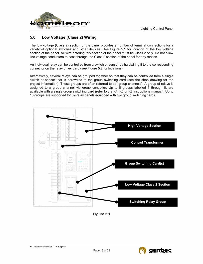
5.0 Low Voltage (Class 2) Wiring The low voltage (Class 2) section of the panel provides a number of terminal connections for a variety of optional switches and other devices. See Figure 5.1 for location of the low voltage section of the panel. All wire entering this section of the panel must be Class 2 only. Do not allow line voltage conductors to pass through the Class 2 section of the panel for any reason. An individual relay can be controlled from a switch or sensor by hardwiring it to the corresponding connector on the relay driver card (see Figure 5.2 for locations). Alternatively, several relays can be grouped together so that they can be controlled from a single switch or sensor that is hardwired to the group switching card (see the shop drawing for the project information). These groups are often referred to as “group channels”. A group of relays is assigned to a group channel via group controller. Up to 8 groups labelled 1 through 8, are available with a single group switching card (refer to the K4, K6 or K8 instructions manual). Up to 16 groups are supported for 32-relay panels equipped with two group switching cards.
1 9
L
24 Vac
8 16
GROUP SELECT
SwRyN
GND
ON OFF
1Sw Sw 2
PROGRAMRUN OPTIONS
COM3 4
ONLYON
ONLYOFF
Kameleon
7
6
5 KC - 401
3
4
2
15
14
13
11
12
10
1 9
L
24 Vac
8 16
GROUP SELECT
SwRyN
GND
ON OFF
1Sw Sw 2
PROGRAMRUN OPTIONS
COM3 4
ONLYON
ONLYOFF
Kameleon
7
6
5 KC - 401
3
4
2
15
14
13
11
12
10
kameleon
RUN PGM
CLEAR
7 8
0
9
ENTER
1
4
2
5
3
6
Figure 5.1
Low Voltage Class 2 Section
Group Switching Card(s)
High Voltage Section
Control Transformer
Switching Relay Group
Lighting Control Panel
K4 - Installation Guide 38371-C Eng.doc
Page 14 of 22
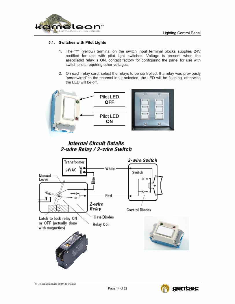
5.1. Switches with Pilot Lights
1. The “Y” (yellow) terminal on the switch input terminal blocks supplies 24V
rectified for use with pilot light switches. Voltage is present when the associated relay is ON, contact factory for configuring the panel for use with switch pilots requiring other voltages.
2. On each relay card, select the relays to be controlled. If a relay was previously
“smartwired” to the channel input selected, the LED will be flashing, otherwise the LED will be off.
Pilot LED OFF
Pilot LED ON
Lighting Control Panel
K4 - Installation Guide 38371-C Eng.doc
Page 15 of 22
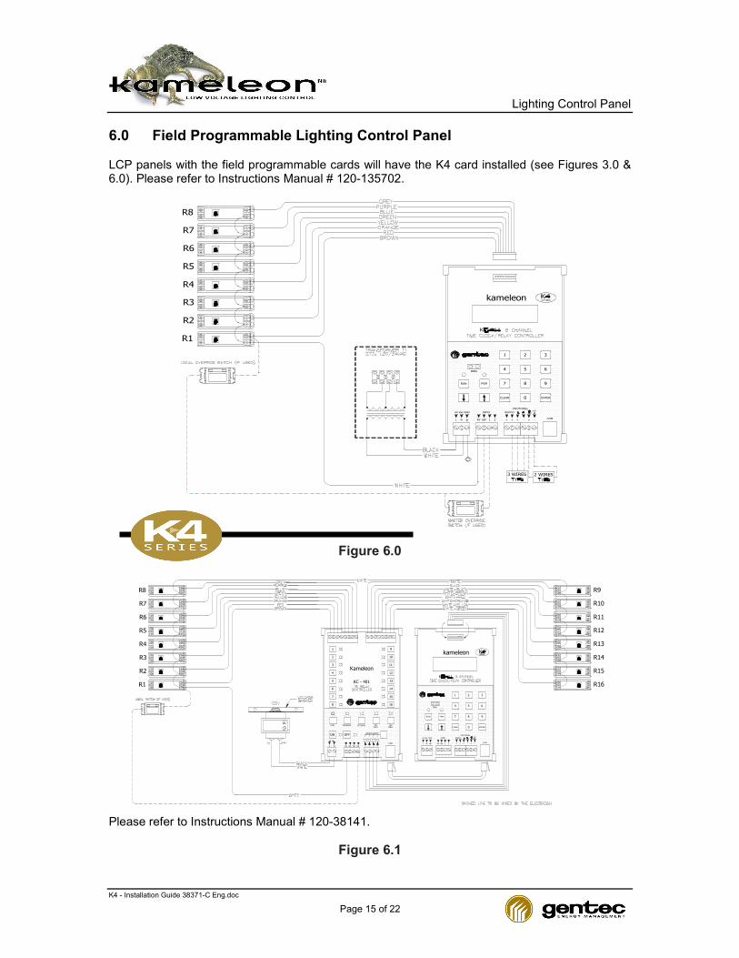
6.0 Field Programmable Lighting Control Panel LCP panels with the field programmable cards will have the K4 card installed (see Figures 3.0 & 6.0). Please refer to Instructions Manual # 120-135702.
R4
R1
R2
R3
R8
R6
R5
R7
GND24 Vac SUPPLYINPUT
L N
2 WIRES
COM
3 WIRES
+SWRY 1 2 + + - + -
IRDA
RUN PGM
CLEAR
7
4
1
0
PHOTOCELL
8
ENTER
9
5
2
6
3
kameleon
Figure 6.0 Please refer to Instructions Manual # 120-38141.
Figure 6.1
KC - 401
Kameleon
OPTIONS
L N
ON
24 Vac
Ry Sw SwSw
OFF
R6
R1
R2
R4
R3
R5
R8
R7
5
8
PROGRAMRUN
7
6
4
2
3
1
1 2 43
GROUP SELECT
COM
13
16
ONONLY ONLY
OFF
15
14
12
10
11
9
R11
R16
R15
R13
R14
R12
R9
R10
kameleon
CLEAR
GND
L N
24 Vac INPUT
SWRY 1 2
RUN PGM
IRDA
987
PHOTOCELL
+ ++
SUPPLY
- -+
0
COM
ENTER
4 5
1 2
6
3
LU

Lighting Control Panel
K4 - Installation Guide 38371-C Eng.doc
Page 16 of 22
6.1. Occupancy Sensor
LCP switch inputs are designed to automatically sense the connection of an occupancy sensor.
The operation of the input will configure for proper operation as soon as the sensor activates the input for the first time. Operation of the occupancy sensor will be determined by the occupancy state of the relay or channel it is controlling. During occupied periods the sensor will turn lighting ON when motion is detected but will not turn the lighting OFF while the relay or channel is in the occupied mode. During unoccupied periods, the sensor will operate normally turning the lighting ON and OFF based on motion detected.
R1
UL
R7
Figure 6.2

Lighting Control Panel
K4 - Installation Guide 38371-C Eng.doc
Page 17 of 22
WIRING CARDS CONFIGURATION IN K4, K6 and K8 series
Each card has a possibility to be installed with other cards for a control lighting applications. The following table will show the cards having the matching possibility for each K series. A number of electronic cards per series grouping/wiring should change base of the number of relay to control per panel (8, 16, 32 or 64 relay panel configuration). Refer to the back panel assembly for the electronic card arrangement and location.
TABLE “A1”
Table of Wiring of Electronic Control Cards for K series TYPICAL WIRING DIAGRAM - Lighting Control Panel
Electronic Cards KC401 ▲ ▲ KC411 ▲ ▲ ▲ KC601 ▲ KC600 ▲ KC621 ▲ KC631 ▲ KC811 ▲ ▲ KC821 ▲ ▲ KC831 ▲ KC832 ▲ KC833 ▲ KC834 ▲ KC841 ▲ ▲ KC842 ▲ KC843 ▲ CDA ▲ ▲ ▲ ▲
XFO - Control ▲ ▲ ▲ ▲

Lighting Control Panel
K4 - Installation Guide 38371-C Eng.doc
Page 18 of 22
TABLE “A2”
Table of Number of Electronic Control Cards for K series
6
3
5
2
4
1
ENTER
9
0
87
CLEAR
PGMRUN
kameleon
6
3
5
2
4
1
ENTER
9
0
87
CLEAR
PGMRUN
kameleon
1 9
L
24 Vac
8 16
GROUP SELECT
SwRyN
GND
ON OFF
1Sw Sw 2
PROGRAMRUN OPTIONS
COM3 4
ONLYON
ONLYOFF
Kameleon
7
6
5 KC - 401
3
4
2
15
14
13
11
12
10
1 9
L
24 Vac
8 16
GROUP SELECT
SwRyN
GND
ON OFF
1Sw Sw 2
PROGRAMRUN OPTIONS
COM3 4
ONLYON
ONLYOFF
Kameleon
7
6
5 KC - 401
3
4
2
15
14
13
11
12
10
Electronic Cards
Cabinet… 8 16 32 64 8 16 32 64 8 16 32 64 16 KC401 1 2 3 4 1 2 3 4 KC411 1 1 1 1 1 1 1 1 KC601 1 1 1 1 KC600 1 1 1 1 KC621 3 4 4 4 KC631 1 3 KC811 1 1 1 1 1 KC821 1 1 2 3 1 KC831 1 2 3 4 1 KC832 1 2 3 4 KC833 1 2 3 4 KC834 1 2 3 4 KC841 1 1 4 KC842 1 1 1 1 1 KC843 1 1 1 1 1 CDA 1 1 1 1 1 1 1 1 1 1 1 1 1 XFO -
Control 1 1 1 1 1 1 1 1 1 1 1 1 1

Lighting Control Panel
K4 - Installation Guide 38371-C Eng.doc
Page 19 of 22
Figure 6.3: Relay Schedule Form
Lighting Control Panel
K4 - Installation Guide 38371-C Eng.doc
Page 20 of 22
7.0 Maintenance For equipment maintenance procedures, refer to the latest edition of NEMA Standards Publication PB1.1 “General Instructions for Proper Installation, Operation, and Maintenance of Panel Boards Rated 600 Volts or Less” which is shipped with the panel and also available on the NEMA web site (www.nema.org). This checklist does not represent an exhaustive survey of maintenance steps, but is necessary to ensure safe operation of the equipment. Particular applications may require further procedures. Should further information be desired or should particular problems arise which are not covered sufficiently for the purchaser’s purposes, refer the matter to the local Gentec Inc. sales office. Dangerous voltages are present in the equipment which can cause death, serious injury or property damage. Always disconnect and lock off all power to the equipment before maintenance. Maintenance should be performed only by qualified personnel. The use of unauthorized parts in the repair of the equipment, or tampering by unqualified personnel will result in dangerous conditions which can cause death, serious injury or equipment damage. Follow all safety instructions contained herein. 8.0 Guarantee Information Gentec Inc. guarantees its Kameleon products to be free of defects in materials. Gentec Inc. for consequential damages arising out of, or in connection with, the use or performance of this product or other indirect damages with respect to loss of property, revenue or profit, or cost of removal, installation or reinstallation.
for Technical Support
USA 888-235-7506 Canada 800-463-4480
2625 Dalton Avenue
Quebec QC G1P 3S9 Canada Technical Support: [email protected]
www.kameleonlightings.com

Lighting Control Panel
K4 - Installation Guide 38371-C Eng.doc
Page 21 of 22
GUARANTEE - CONDITIONS
1. Subject to and strictly according to the terms and conditions set
out below, Gentec Inc. guarantees that its Gentec Inc. Kameleon systems and its low tension lighting systems installed new (hereinafter collectively referred to as the "System") as well as each of the original components of these Systems, sold indivi-dually (the "Components") are free from all manufacturing faults and defects (the Guarantee on “New Equipment").
First Purchaser 2. The Guarantee on New Equipment is for the benefit of and
applies only to the first purchaser of a System or a Component. This guarantee is non-transferable.
Duration of Guarantee 3. a) The Guarantee on New Equipment applicable to the System
extends for a period of one year and six months, as calculated from the date the System was shipped to the client by Gentec Inc.
b) The Guarantee on New Equipment applicable to the Com-
ponent sold individually extends for a period of one year as calculated from the date of their shipment to the client by Gentec Inc.
Guarantee on Repairs 4. Subject to and strictly according to the terms and conditions set
out below, any repairs carried out by the workshops of Gentec Inc. is also guaranteed free from faults and defects for a period of sixty (60) days as calculated from the date Gentec Inc. shipped the repaired product to the client. This guarantee applies only to Systems and Components sold by Gentec Inc. or its authorized retailers and for which the Guarantee on New Equipment is expired and as regards a repair is billed to the client and duty paid by the client (the "Guarantee on Repairs").
Specific Conditions Applicable to the Guarantee on New Equip-ment 5. In its sole discretion, but subject to the clause "Exclusion from the
Guarantee", Gentec Inc. will replace or repair at its expenses (parts and labour), any System or Component or parts thereof which in its opinion are affected by a manufacturing fault or defect and which are returned to it for repair or replacement before the expiration of the Guarantee.
Specific Conditions Applicable to the Guarantee on Repairs 6. Subject to the clause "Exclusion from the Guarantee", Gentec
Inc. will rectify at its expenses any repair carried out by it in its workshops, if in its opinion, it appears that the previous repair was faulty or defective, on the condition that the client returns the previously repaired object to Gentec Inc. before the expiration of this Guarantee. Any repairs carried out pursuant to this Guarantee are also guaranteed for the period and according to the conditions outlined in paragraph 4.
General Conditions Applicable to the Guarantee on New Equip-ment and the Guarantee on Repairs (hereinafter collectively referred to as the "Guarantee") 7. a) The removal or installation of a System or a Component or
any part thereof (hereinafter referred to as the "Product") is the responsibility of the client. All related expenses are assumed by the client.
b) The shipping of a Product to Gentec Inc. is the res-
ponsibility of the client. Such Product must be shipped pre-paid to Gentec Inc. accompanied by the Gentec Inc. au-thorization number. Return shipping expenses for the client's Product are paid by the client.
c) Pursuant to the terms of this Guarantee, the obligation of Gentec Inc. is, in accordance with the Guarantee ap-plicable to the Product, exclusively and strictly limited to the repair or replacement of a Product or the rectification of a repair already completed by Gentec Inc. in its workshops. This Guarantee is the only one applicable to the Products to the exclusion of any other guarantees, representations or undertakings whatso-ever made by Gentec Inc, it’s employees, agents or re-presentatives. Without limiting the generality of the foregoing, the Guarantee cancels and expressly re-places all other express or tacit guarantees or conditions. The Guarantee neither constitutes nor confers any guarantee or representation as to the marketing or the adaptability of a product for arty particular use. For the period that the Guarantee on New Equipment applies, Gentec Inc. guarantees suf-ficient availability of parts to repair or replace a Product. However, it is expressly agreed that Gentec Inc. may from time to time and at all time modify, discontinue or replace its Product without advising the client and without incurring any liability or obligation whatsoever. Furthermore, Gentec Inc. cannot under any circumstances, be held liable for any direct or indirect damages to the client resulting from the possession or the use of a Product, including without limitations, all damages relating to shipping cofets of a Product, labour charges for the removal or installation of a Product, communication or travelling expenses, pe-cuniary losses or other material or physical damages, loss of income, loss of use of the Product or any other loss of any nature whatsoever. In the event a Product is sent to Gentec Inc. Invoking the Guarantee and Gentec Inc. considers that for any reason(s) outlined in its Limited Guarantee, the Guarantee does not apply, the cost of all work, repair or replacement in whole or in part, carried out by Gentec Inc. shall be assumed by the client in accordance the hourly rates and the price of parts applicable at that time.
Exclusion from the Guarantee 8. This Guarantee is null and without effect in any or all of the
following situations: a) non-maintenance or insufficient maintenance of a Pro-
duct or part of a Product; b) improper or inadequate use or treatment of the Product or
part of the Product, including all damages or improper treatments resulting from the shipment of the Product, including shipment of the Product by Gentec Inc. to the client; faulty installation or improper integration of the Product or a part of the Product, unless the same is performed by Gentec Inc., its employees or agents; or
c) modifications or alterations or attempted modifications or
alterations of the Product or any part thereof without the authorization of Gentec Inc. (if a modification or alter-ation is made by the client with the authorization of Gentec Inc., this authorization must be produced with any request for work under the Guarantee).
For any additional information, please contact your Gentec Inc. System authorized distributor or Gentec Inc. directly at the following address:
Gentec Inc. Energy Management Division
2625 Dalton Avenue Quebec QC G1P3S9 Canada

Lighting Control Panel
K4 - Installation Guide 38371-C Eng.doc
Page 22 of 22