General Instructions for Series II Digital Mass Flow ... Instructions for Series II Digital Mass ......
36
General Instructions for Series II Digital Mass Flow / Pressure Instruments Attention Please read this instruction manual carefully before installing and operating the instrument. Not following the guidelines could result in personal injury and or damage to the equipment. FM-1273 Rev C 8/14
Transcript of General Instructions for Series II Digital Mass Flow ... Instructions for Series II Digital Mass ......

General Instructions for Series II Digital Mass Flow / Pressure Instruments
Attention Please read this instruction manual carefully before installing and operating the instrument. Not following the guidelines could result in personal injury and or damage to the equipment.
FM-1273 Rev C 8/14


Porter
SCOPE OF THIS MANUAL This manual covers the general part of digital mass flow / pressure instruments for gases. It handles the general instructions needed for the instruments. Multibus instruments have modular instruction manuals consisting of: - General instructions: Series ll Digital Mass Flow / Pressure instruments
(document FM-1273)
- Operation instructions digital instruments (document FM-1245)
- Fieldbus/interface description: - FLOW-BUS interface (document FM-1246) - PROFIBUS–DP interface (document FM-1247) - DeviceNet interface (document FM-1248) - RS232 interface with FLOW-BUS protocol (document FM-1249) - Modbus interface (document FM-1250) - EtherCAT® interface (document FM-1253)
Please visit http://www.porterinstrument.com/resources for additional user manuals.
page 3 FM-1273

Porter
Even though care has been taken in the preparation and publication of the contents of this manual, we do not assume legal or other liability for any inaccuracy, mistake, misstatement or any other error of whatsoever nature contained herein. The material in this manual is for information purposes only, and is subject to change without notice.
Porter Instrument Division August 2014
page 4 FM-1273

Porter
Short-Form Operation Instruction Before installing your Mass Flow or Pressure Meter/Controller it is important to read the label attached to the flow Meter/Controller and check: - flow/pressure rating - fluid to be metered - up and downstream pressures - input/output signal Check the red-colored sticker and make sure the listed test pressure is in agreement with normal safety factors for your application. Check if the piping system is clean. For absolute cleanliness always install filters to assure a clean, moisture and oil-free gas stream. Install the Meter/Controller in the line and tighten the fittings according to the instructions of the supplier of the fittings. Choose the mounting position according to the directions given in this manual. Check the system for leaks before applying fluid pressure In systems with corrosive or reactive fluids, purging with an inert gas is absolutely necessary before use. Complete purging after use with corrosive or reactive fluids is also required before exposing the system to air.
http://www.porterinstrument.com/resources . Short form start-up
Install instrument in your process. Provide instrument with correct pressure(s) Analog operation Connect the instrument to the power supply/readout unit with the 9-pin cable at the DB-9 connector / 8 DIN connector
Electrical connections must be made with a standard cable or according to the hook-up diagrams which are available on the FM-1271 documentation/software tool CD or from the factory. Additional information can be found at:
page 5 FM-1273

Porter
BUS/digital operation For this procedure: See descriptions for specific fieldbus protocol.
Send a setpoint to the instrument and check the measured value Let the instrument warm-up for 30 minutes for best accuracy Your Mass Flow/Pressure Meter/Controller is now ready for operation. Caution Operation via fieldbus is done by means of a flat conductor cable connected with the main PC board. Although all functionality is possible by means of RS232 and the switch on top of the instrument, it is important that care should be taken when removing the upper part of the housing.
page 6 FM-1273
Porter
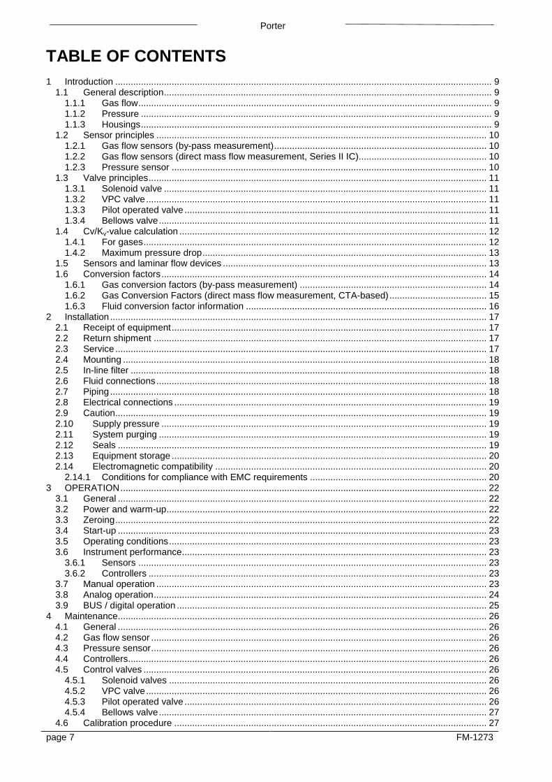
TABLE OF CONTENTS 1 Introduction ................................................................................................................................................... 9
1.1 General description ................................................................................................................................ 9 1.1.1 Gas flow .......................................................................................................................................... 9 1.1.2 Pressure ......................................................................................................................................... 9 1.1.3 Housings ......................................................................................................................................... 9
1.2 Sensor principles ................................................................................................................................. 10 1.2.1 Gas flow sensors (by-pass measurement) ................................................................................... 10 1.2.2 Gas flow sensors (direct mass flow measurement, Series II IC).................................................. 10 1.2.3 Pressure sensor ........................................................................................................................... 10
1.3 Valve principles .................................................................................................................................... 11 1.3.1 Solenoid valve .............................................................................................................................. 11 1.3.2 VPC valve ..................................................................................................................................... 11 1.3.3 Pilot operated valve ...................................................................................................................... 11 1.3.4 Bellows valve ................................................................................................................................ 11
1.4 Cv/Kv-value calculation ........................................................................................................................ 12 1.4.1 For gases ...................................................................................................................................... 12 1.4.2 Maximum pressure drop ............................................................................................................... 13
1.5 Sensors and laminar flow devices ....................................................................................................... 13 1.6 Conversion factors ............................................................................................................................... 14
1.6.1 Gas conversion factors (by-pass measurement) ......................................................................... 14 1.6.2 Gas Conversion Factors (direct mass flow measurement, CTA-based) ...................................... 15 1.6.3 Fluid conversion factor information .............................................................................................. 16
2 Installation ................................................................................................................................................... 17 2.1 Receipt of equipment ........................................................................................................................... 17 2.2 Return shipment .................................................................................................................................. 17 2.3 Service ................................................................................................................................................. 17 2.4 Mounting .............................................................................................................................................. 18 2.5 In-line filter ........................................................................................................................................... 18 2.6 Fluid connections ................................................................................................................................. 18 2.7 Piping ................................................................................................................................................... 18 2.8 Electrical connections .......................................................................................................................... 19 2.9 Caution ................................................................................................................................................. 19 2.10 Supply pressure ............................................................................................................................... 19 2.11 System purging ................................................................................................................................ 19 2.12 Seals ................................................................................................................................................ 19 2.13 Equipment storage ........................................................................................................................... 20 2.14 Electromagnetic compatibility .......................................................................................................... 20
2.14.1 Conditions for compliance with EMC requirements ..................................................................... 20 3 OPERATION ............................................................................................................................................... 22
3.1 General ................................................................................................................................................ 22 3.2 Power and warm-up ............................................................................................................................. 22 3.3 Zeroing ................................................................................................................................................. 22 3.4 Start-up ................................................................................................................................................ 23 3.5 Operating conditions ............................................................................................................................ 23 3.6 Instrument performance ....................................................................................................................... 23
3.6.1 Sensors ........................................................................................................................................ 23 3.6.2 Controllers .................................................................................................................................... 23
3.7 Manual operation ................................................................................................................................. 23 3.8 Analog operation .................................................................................................................................. 24 3.9 BUS / digital operation ......................................................................................................................... 25
4 Maintenance................................................................................................................................................ 26 4.1 General ................................................................................................................................................ 26 4.2 Gas flow sensor ................................................................................................................................... 26 4.3 Pressure sensor ................................................................................................................................... 26 4.4 Controllers............................................................................................................................................ 26 4.5 Control valves ...................................................................................................................................... 26
4.5.1 Solenoid valves ............................................................................................................................ 26 4.5.2 VPC valve ..................................................................................................................................... 26 4.5.3 Pilot operated valve ...................................................................................................................... 26 4.5.4 Bellows valve ................................................................................................................................ 27
4.6 Calibration procedure .......................................................................................................................... 27 page 7 FM-1273

Porter
5 Digital instrument ........................................................................................................................................ 28 6 Interface description .................................................................................................................................... 28 7 TROUBLESHOOTING ................................................................................................................................ 28
7.1 General ................................................................................................................................................ 28 7.2 Troubleshooting summary general ...................................................................................................... 29
8 POLICIES AND CERTIFICATE OF WARRANTY ...................................................................................... 30 8.1 Policies ................................................................................................................................................. 30 8.2 Prices ................................................................................................................................................... 30 8.3 Payment Terms ................................................................................................................................... 30 8.4 Shipments ............................................................................................................................................ 30 8.5 Cancellations ....................................................................................................................................... 30 8.6 Changes of Order ................................................................................................................................ 30 8.7 Returns ................................................................................................................................................ 30 8.8 Certificate of Warranty ......................................................................................................................... 30
Appendices 1 Gas conversion table 2 Dimensions digital cases 3 Enclosures (if applicable)
page 8 FM-1273

PORTER
1 Introduction 1.1 General description
1.1.1 Gas flow The Porter Instrument Series II gas mass flow devices are an accurate device for measurement and control of gas flows from 1 ml/min up to several thousand m3/h, virtually independent of pressure and temperature changes. These devices are available at system pressures up to 700 bar (10,153 PSI) depending on model and body rating. These devices are available with or without a control valve to meter or control gas flow.
1.1.2 Pressure The Porter pressure devices measure pressures from 100 mbar to 400 bar (1.45 psi to 5,800 psi) in gauge or absolute pressure ranges. Differential pressure devices are available in the range of 0 to 15 bar (0 to 200 psid). The pressure controllers control forward pressure (P-600 series) and back pressure (P-700 series) with a very high accuracy and repeatability. Flow rates vary by model and application. The flow going through the pressure controller depends on up and downstream pressures, the orifice diameter of the valve and the type of fluid.
1.1.3 Housings Each instrument housing style incorporates several provisions to comply with EMC requirements. Series: II S, II B, II HP, II DF, II P, II SM, II FS, II PM, II FS (Standard Configuration)
The PCB is placed in a metalized plastic cover. For electrical connection the instrument has a male 9-pin miniature sub-D connector for analog/RS232 operation. For digital operation, the instrument has various connectors on the top of the cover. These instruments are suitable for dry (indoor) applications, like laboratories and protected (OEM) housings.
Series: II IS, II IP, II DF, II IC, II IH, II HP (Industrial Configuration)
To comply with the IP65 ingress protection standard, the PCB is housed in a sealed cast metal housing. For electrical connections, the instrument has an 8-DIN male connector for analog/RS232 operation, and for digital operation, various connectors on the top of the housing. These instruments are suited for light industrial (outdoor) use to IP65.
SERIES: II IS,
SEIRES II IP
page 9 FM-1273
PORTER
1.2 Sensor principles
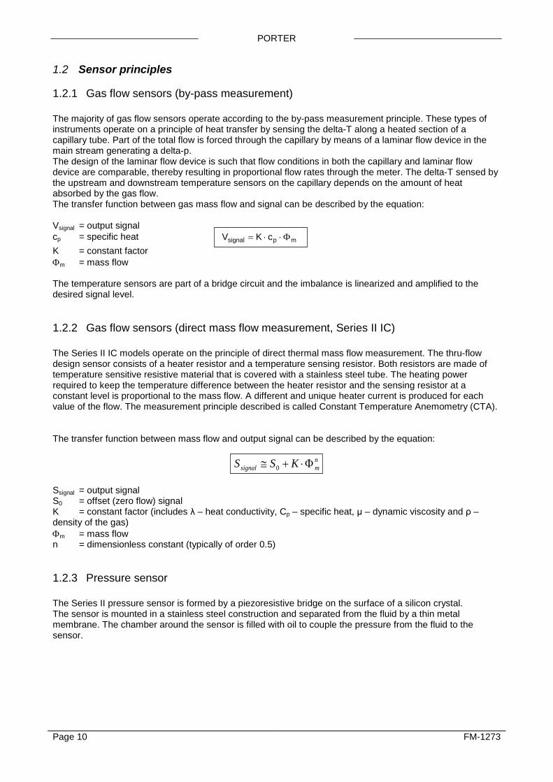
1.2.1 Gas flow sensors (by-pass measurement) The majority of gas flow sensors operate according to the by-pass measurement principle. These types of instruments operate on a principle of heat transfer by sensing the delta-T along a heated section of a capillary tube. Part of the total flow is forced through the capillary by means of a laminar flow device in the main stream generating a delta-p. The design of the laminar flow device is such that flow conditions in both the capillary and laminar flow device are comparable, thereby resulting in proportional flow rates through the meter. The delta-T sensed by the upstream and downstream temperature sensors on the capillary depends on the amount of heat absorbed by the gas flow. The transfer function between gas mass flow and signal can be described by the equation: Vsignal = output signal cp = specific heat V K csignal p m= ⋅ ⋅ Φ K = constant factor Φm = mass flow The temperature sensors are part of a bridge circuit and the imbalance is linearized and amplified to the desired signal level.
1.2.2 Gas flow sensors (direct mass flow measurement, Series II IC) The Series II IC models operate on the principle of direct thermal mass flow measurement. The thru-flow design sensor consists of a heater resistor and a temperature sensing resistor. Both resistors are made of temperature sensitive resistive material that is covered with a stainless steel tube. The heating power required to keep the temperature difference between the heater resistor and the sensing resistor at a constant level is proportional to the mass flow. A different and unique heater current is produced for each value of the flow. The measurement principle described is called Constant Temperature Anemometry (CTA). The transfer function between mass flow and output signal can be described by the equation:
nmsignal KSS Φ⋅+≅ 0
Ssignal = output signal S0 = offset (zero flow) signal K = constant factor (includes λ – heat conductivity, Cp – specific heat, μ – dynamic viscosity and ρ – density of the gas) Φm = mass flow n = dimensionless constant (typically of order 0.5)
1.2.3 Pressure sensor The Series II pressure sensor is formed by a piezoresistive bridge on the surface of a silicon crystal. The sensor is mounted in a stainless steel construction and separated from the fluid by a thin metal membrane. The chamber around the sensor is filled with oil to couple the pressure from the fluid to the sensor.
Page 10 FM-1273

PORTER
1.3 Valve principles Control valves are not designed to provide positive shut-off, although some models have excellent capabilities for this purpose. It is recommended to install a separate shut-off valve in the line if so required. Also pressure surges, as may occur during system pressurization must be avoided. The following models may be incorporated::
1.3.1 Solenoid valve This is considered to be the standard (direct operated) control valve. In general it is a normally closed solenoid valve. The plunger is lifted by the force of the magnetic field of the coil. The orifice under the plunger is removable for optimizing the orifice diameter. A normally opened solenoid valve is also available.
1.3.2 VPC valve
For process conditions where up and downstream pressures may vary significantly, a special type of valve, VPC or Variable Pressure Compensation valve has been designed. This valve consists of two valves, a solenoid operated control valve and a fixed adjusted pressure compensation valve.
1.3.3 Pilot operated valve
For high flow rates the pilot operated valve has been designed. A solenoid driven control valve controls the pressure difference across a piston, which lifts the main plunger.
1.3.4 Bellows valve This valve type is a direct driven, low power, solenoid operated control valve. A special design, incorporating a metal bellows allows for a relatively large orifice opening to be controlled. The design is suited for low pressure or vacuum applications.
flowcontrol valve
pressurecompensatingvalve
flowcontrol valve
P1
pilot valve pressure compensating valve
P2
flowcontrol valve
Page 11 FM-1273

PORTER
1.4 Cv/Kv-value calculation This calculation method can be used to determine the Kv-value of the main orifice of a control valve.
Kv is the flow coefficient in metric units. It is defined as the flow rate in cubic meters per hour [m3/h] of water at a temperature of 16º celsius with a pressure drop across the valve of 1 bar. Cv is the flow coefficient in imperial units. It is defined as the flow rate in US Gallons per minute [gpm] of water at a temperature of 60º fahrenheit with a pressure drop across the valve of 1 psi.
Kv = 0.865 · Cv Cv = 1,156 · Kv
1.4.1 For gases Determine desired ∆p across valve. ∆p must be at least 20% of supply pressure, or in closed loop systems, 20% of total pressure difference in loop. If ∆p is 20-50% of supply pressure, use formula:
KT
p pvvn n=
⋅⋅
Φ∆514 2
ρ undercritical
If ∆P is 50-100% of supply pressure, use formula:
Kp
Tvvn
n=⋅
⋅Φ
257 1ρ overcritical
Units: Φvn = flow [mn
3/h] p1 = supply pressure [bara] p2 = downstream pressure [bara] ∆p = pressure difference (p1 - p2) [bara] T = temperature [K] ρn = density [kg/mn
3]
The orifice diameter can be determined by: d= 7.6 K v [mm]
Page 12 FM-1273
PORTER
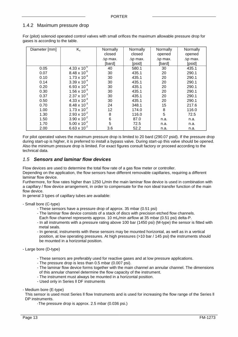
1.4.2 Maximum pressure drop For (pilot) solenoid operated control valves with small orifices the maximum allowable pressure drop for gases is according to the table.
Diameter [mm] Kv Normally closed ∆p max. [bard]
Normally closed ∆p max.
[psid]
Normally opened ∆p max. [bard]
Normally opened ∆p max.
[psid] 0.05 0.07 0.10 0.14 0.20 0.30 0.37 0.50 0.70 1.00 1.30 1.50 1.70 2.00
4.33 x 10⁻⁵ 8.48 x 10⁻⁵ 1.73 x 10⁻⁴ 3.39 x 10⁻⁴ 6.93 x 10⁻⁴ 1.56 x 10⁻³ 2.37 x 10⁻³ 4.33 x 10⁻³ 8.48 x 10⁻³ 1.73 x 10⁻² 2.93 x 10⁻² 3.90 x 10⁻² 5.00 x 10⁻² 6.63 x 10⁻²
40 30 30 30 30 30 30 30 24 12 8 6 5
3.6
580.1 435.1 435.1 435.1 435.1 435.1 435.1 435.1 348.1 174.0 116.0 87.0 72.5 52.2
30 20 20 20 20 20 20 20 15 8 5
n.a. n.a. n.a.
435.1 290.1 290.1 290.1 290.1 290.1 290.1 290.1 217.6 116.0 72.5 n.a. n.a. n.a.
For pilot operated valves the maximum pressure drop is limited to 20 bard (290.07 psid). If the pressure drop during start-up is higher, it is preferred to install a bypass valve. During start-up this valve should be opened. Also the minimum pressure drop is limited. For exact figures consult factory or proceed according to the technical data. 1.5 Sensors and laminar flow devices Flow devices are used to determine the total flow rate of a gas flow meter or controller. Depending on the application, the flow sensors have different removable capillaries, requiring a different laminar flow device. Furthermore, for flow rates higher than 1250 ln/min the main laminar flow device is used in combination with a capillary / flow device arrangement, in order to compensate for the non ideal transfer function of the main flow device. In general 3 types of capillary tubes are available: - Small bore (C-type) - These sensors have a pressure drop of approx. 35 mbar (0.51 psi) - The laminar flow device consists of a stack of discs with precision etched flow channels. Each flow channel represents approx. 10 mln/min airflow at 35 mbar (0.51 psi) delta-P.
- In all instruments with a pressure rating above 100 bar (1450 psi) (M-type) the sensor is fitted with metal seals.
- In general, instruments with these sensors may be mounted horizontal, as well as in a vertical position, at low operating pressures. At high pressures (>10 bar / 145 psi) the instruments should be mounted in a horizontal position. - Large bore (D-type) - These sensors are preferably used for reactive gases and at low pressure applications. - The pressure drop is less than 0.5 mbar (0.007 psi). - The laminar flow device forms together with the main channel an annular channel. The dimensions of this annular channel determine the flow capacity of the instrument. - The instrument must always be mounted in a horizontal position. - Used only in Series ll DF instruments - Medium bore (E-type)
This sensor is used most Series ll flow Instruments and is used for increasing the flow range of the Series ll DP instruments.
-The pressure drop is approx. 2.5 mbar (0.036 psi.)
Page 13 FM-1273

PORTER
1.6 Conversion factors
1.6.1 Gas conversion factors (by-pass measurement) The general formula for determining the relationship between signal and mass flow is:
V K c K csignal p m p v= ⋅ ⋅ = ⋅ ⋅ ⋅Φ Φρ in which: Vsignal = output signal K = constant ρ = density cp = specific heat Φm = mass flow Φv = volume flow As soon as the cp value and density of the gas to be metered change, the signal must be corrected. The conversion factor C is:
Ccc
p
p=
⋅
⋅1
2
1
2
ρ
ρ
in which: cp = specific heat ρn = density at normal conditions (1) gas calibrated (2) gas to be measured Note: The cp value used for the calculation of the conversion factor must be taken at a temperature approx. 50°C. higher than the required temperature. This factor is called cp cal. The conversion factors for commonly used gases related to N2 at normal conditions are stated in the Gas Conversion Table in the appendix 1. Example: Meter calibrated on N2 (200 mln/min). Gas flow passing the meter is CO2. Output signal reads 80.0%.
Actual CO2 flow = 80.0 ⋅ 0.741.00
= 59.2%
so 59 2100
.⋅ 200 = 118.4 mln/min
* n means normal conditions At normal conditions, volumes are converted to a temperature of 0°C and pressure of 1 atm or 1013,25 mbar. (760 Torr) Note: Best accuracy is always achieved by performing calibration under operating conditions. Should this not be possible or practical, then the use of a theoretical conversion factor is a means to determine the flow rate of the instrument on the gas to be metered, however, it will introduce inaccuracies.
Page 14 FM-1273
PORTER
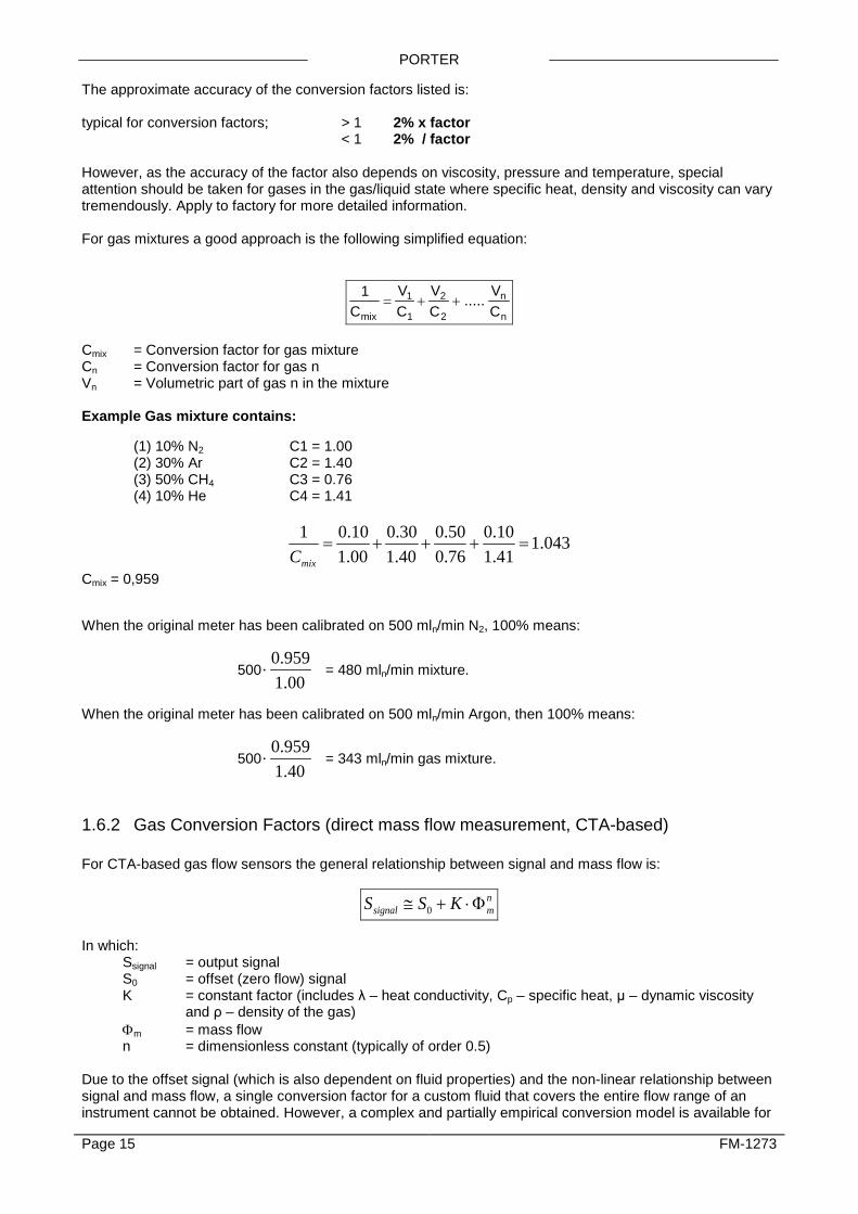
The approximate accuracy of the conversion factors listed is: typical for conversion factors; > 1 2% x factor < 1 2% / factor However, as the accuracy of the factor also depends on viscosity, pressure and temperature, special attention should be taken for gases in the gas/liquid state where specific heat, density and viscosity can vary tremendously. Apply to factory for more detailed information. For gas mixtures a good approach is the following simplified equation:
1 1
1
2
2CVC
VCmix
= + + .....VC
n
n
Cmix = Conversion factor for gas mixture Cn = Conversion factor for gas n Vn = Volumetric part of gas n in the mixture Example Gas mixture contains: (1) 10% N2 C1 = 1.00 (2) 30% Ar C2 = 1.40 (3) 50% CH4 C3 = 0.76 (4) 10% He C4 = 1.41
043.141.110.0
76.050.0
40.130.0
00.110.01
=+++=mixC
Cmix = 0,959 When the original meter has been calibrated on 500 mln/min N2, 100% means:
50000.1959.0
⋅ = 480 mln/min mixture.
When the original meter has been calibrated on 500 mln/min Argon, then 100% means:
50040.1959.0
⋅ = 343 mln/min gas mixture.
1.6.2 Gas Conversion Factors (direct mass flow measurement, CTA-based) For CTA-based gas flow sensors the general relationship between signal and mass flow is:
nmsignal KSS Φ⋅+≅ 0
In which: Ssignal = output signal S0 = offset (zero flow) signal K = constant factor (includes λ – heat conductivity, Cp – specific heat, μ – dynamic viscosity
and ρ – density of the gas) Φm = mass flow n = dimensionless constant (typically of order 0.5) Due to the offset signal (which is also dependent on fluid properties) and the non-linear relationship between signal and mass flow, a single conversion factor for a custom fluid that covers the entire flow range of an instrument cannot be obtained. However, a complex and partially empirical conversion model is available for
Page 15 FM-1273
PORTER
most common gases, which is accurate at both lower and higher flow ranges. Consult Porter Instrument for applications.
1.6.3 Fluid conversion factor information Contact the factory for more information on conversion factors, at any temperature/pressure combination, when converting to different fluids and gases.
Page 16 FM-1273

PORTER
2 Installation 2.1 Receipt of equipment Check the outside packing box for damage incurred during shipment. Should the packing box be damaged, then the local carrier must be notified at once regarding his liability, if so required. At the same time a report should be submitted to:
Parker Hannifin Corporation Porter Instrument Division Hatfield Pa (215) 723-4000
If applicable, otherwise contact your distributor. Remove the envelope containing the packing list; carefully remove the equipment from the packing box. Do not discard spare or replacement parts with the packing material and inspect the contents for damaged or missing parts.
2.2 Return shipment When returning material, always describe the problem and if possible the work to be done, in a cover letter. It is absolutely required to notify the factory if toxic or dangerous fluids have been metered with the instrument! Contact Porter Instrument Division (215) 723-4000 for a return authorization (RA) forms if an MFM or MFC is to be returned for any reason. The RA form, along with a Declaration of Contamination form and a Material Safety Data Sheet, must accompany all return shipments. If the MFM or MFC was used with corrosive and/or toxic gases, the customer is responsible for removing all traces of hazardous materials prior to shipment. Detail the conditions of purging used. Porter is to be notified about application conditions before any MFM or MFC will be serviced. Items must be properly packed and shipped prepaid 2.3 Service Only factory service is available. Contact your local Parker Sales office. In the US contact the Porter factory or send an email describing the problem to [email protected].
Page 17 FM-1273
PORTER
2.4 Mounting The mounting position depends on the type of instrument. For flowmeters the preferred position is horizontal, and at high pressures all meters should be mounted in this position. Avoid installation in close proximity of mechanic vibration and / or heat sources. All flow metering and flow control devices should be mounted in straight lines for highest accuracy. This is how the devices are calibrated. Plumbing elements such as fitting elbows or shutoff valves will have a negative impact. A minimum of 10 diameters is recommended for functional metering and control. Flow straighteners may improve accuracy in complex systems where the flow profile is significantly disturbed. 2.5 In-line filter Although fluids to be measured should be absolutely free of dirt, oil, moisture and other particles, it is recommended to install an in-line filter upstream of the flowmeter / controller, and if backflow can occur, a downstream filter is also recommended. Be aware of the pressure drop caused by the filter. On the inlet of some instruments a screen is placed to prevent foreign matter from entering the instrument and to maintain a good flow pattern. This device cannot be used as a reliable filter element. Contact factory for further information. 2.6 Fluid connections Porter meters / controllers are equipped with compression type or face-seal-fittings. For most of the instruments, these fittings are British Standard Pipe (BSP) parallel thread types which have to be used in combination with elastomeric O-rings to seal to the instrument. For some instruments, these fittings are orbital welded to the body. For leak tight installation of compression type fittings, be sure that the tube is inserted to the shoulder in the fitting body and that no dirt or dust is present on tube, ferrules or fittings. Tighten the nut finger tight; while holding the instrument, then tighten the nut as directed by the fitting manufacturer. Special types of fittings are available on request. The flanges also must fit well to each other and seals should not protrude into the flow path. * Note: Always check your system for leaks, before applying fluid pressure. Especially if toxic, explosive or
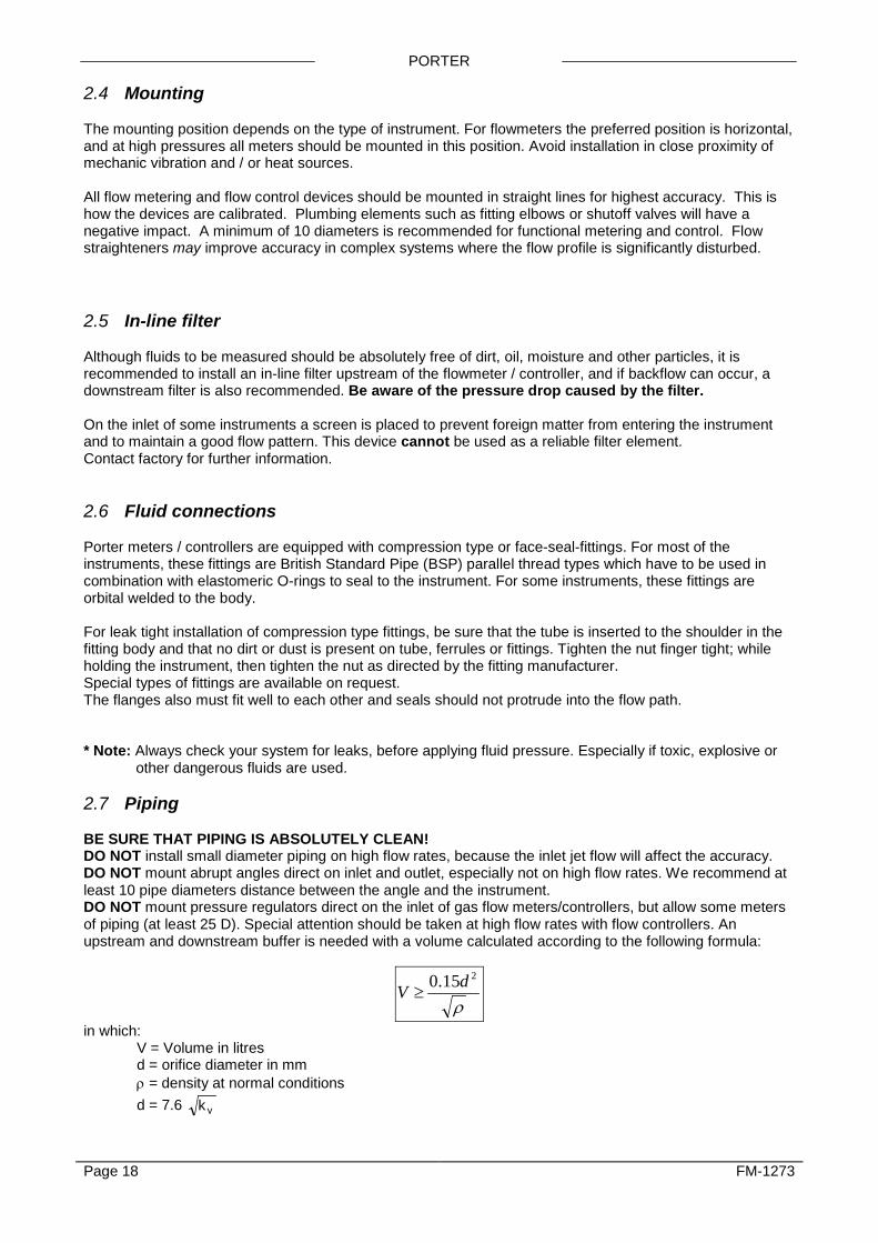
other dangerous fluids are used. 2.7 Piping BE SURE THAT PIPING IS ABSOLUTELY CLEAN! DO NOT install small diameter piping on high flow rates, because the inlet jet flow will affect the accuracy. DO NOT mount abrupt angles direct on inlet and outlet, especially not on high flow rates. We recommend at least 10 pipe diameters distance between the angle and the instrument. DO NOT mount pressure regulators direct on the inlet of gas flow meters/controllers, but allow some meters of piping (at least 25 D). Special attention should be taken at high flow rates with flow controllers. An upstream and downstream buffer is needed with a volume calculated according to the following formula:
ρ
215.0 dV ≥
in which: V = Volume in litres d = orifice diameter in mm ρ = density at normal conditions d = 7.6 k v
Page 18 FM-1273

PORTER
Example: Flow controller at 500 ln/min Air and orifice diameter d = 4 mm, (0.157”), needs for stable control a buffer volume of:
1.229.1:415.0 2 =⋅≥V litres Also the capacity of the pressure regulator should be at least 2 times the flow controller, so in this case 2 ⋅ 500 = 1,000 ln/min. 2.8 Electrical connections Porter recommends using their standard cables. These cables have the right connectors and if loose ends are used, these will be marked to prevent incorrect connections. Hook-up diagrams are available on the FM-1271 documentation/software tool CD or from the factory. . To comply with the IP classification, it is necessary to follow the assembly guidelines of the connector manufacturer. 2.9 Caution Each meter/controller is pressure tested to at least 1.5 times the working pressure of the process conditions stipulated by the customer, with a minimum of 8 bar (116 psi). For pressure meter/controllers, the test pressure depends on the range of the pressure transducer. The tested pressure is stated on the flow meter/controller with a RED COLORED sticker. Check test pressure before installing in the line. If the sticker is not present or the test pressure is incorrect, the instrument should not be mounted in the process line and must be returned to the factory. Each instrument is helium leak tested to at least 2⋅10-9 mbar l/s Helium. 2.10 Supply pressure Do not apply pressure until electrical connections are made. When applying pressure to the system, take care to avoid pressure shocks in the system and increase pressure gradually, especially on high pressure units incorporating a piston operated control valve. 2.11 System purging If explosive gases are to be used, purge the process with inert dry gas like Nitrogen, Argon etc. for at least 30 minutes. In systems with corrosive or reactive fluids, purging with an inert gas is absolutely necessary, because if the tubing has been exposed to air, introducing these fluids will tend to clog up or corrode the system due to a chemical reaction with oxygen or moist air. Complete purging is also required to remove such fluids from the system before exposing the system to air. It is preferred not to expose the system to air, when working with these corrosive fluids. 2.12 Seals Porter has gathered a material compatibility chart from a number of sources believed to be reliable. However, it is only a general guide. Please contact the factory for information on material compatibility. Operating conditions may substantially change the accuracy of this guide. Therefore there is no liability for damages accruing from the use of this information. The customer’s application will demand its own specific design or test evaluation for optimum reliability. Please check that the seals like O-rings, plunger and packing gland of capillary are correct for the process.
Page 19 FM-1273

PORTER
Fold the shield of the cable back over the cable (the shield must be around the cable).
Wind a copper tape around the shield Solder a black wire on the tape and connect to pin 9 of the connector.
copper tape
shielded cable e.g. LAPP LiYCY
other wires D-connector housing metalized.
connector
8 mm 20 mm
Black wire (shield)
2.13 Equipment storage The equipment should be stored in its original packing. Care should be taken not to subject the equipment to excessive temperatures or humidity. 2.14 Electromagnetic compatibility
2.14.1 Conditions for compliance with EMC requirements All instruments described in this manual carry the CE-mark. Therefore they have to comply with the EMC requirements as are valid for these instruments. However compliance with the EMC requirements is not possible without the use of proper cables and connector/gland assemblies. For good results Porter can provide standard cables. Otherwise follow the guidelines as stated below. D-Connector assembly
Page 20 FM-1273

PORTER
8DIN connector assembly Notes: 1. When connecting the system to other devices (e.g. to PLC), be sure that the integrity of the shielding is
not affected. Do not use unshielded wire terminals. 2. For FLOW-BUS / Modbus S(F)TP data (patch) cable connection to RJ45 connectors follow the
instructions of the supplier. It is important to use shielded twisted pair cables and shielded RJ45 modular jack connectors.
3. When using Modbus you must use Modbus hook up diagram available on FM1271 CD 4. For PROFIBUS-DP or DeviceNet data cable connections follow the instructions of the cable suppliers for
the specific field-bus system.
Shrink soldercontacts with shrinktubing
Shield of the cable should beconnected to the connectorhousing
BRE 160 black or eq.
O-Ring
8 DIN connector AmphenolSerie C091 31D008 200 2
Transparant tubing
Cable LIYCY 8x0.25mm
Fold the shield of the cable back overthe cable. (The shield must be around
20 mm
2.5
the cable)
2
Metal ring
Solder-side Amphenol 8-pinDIN connector female
5
7
3
86
24
1
Detail
Serie 423 99.5672.19.08
O-Ring
Detail
Black tubing
8 DIN Connector Binder
Cable LIYCY 8x0.25mm
20 mm
4.02
Shield of the cable should beconnected to the connectorhousing
Fold the shield of the cable back overthe cable. (The shield must be aroundthe cable)
BRE 160 black or eq.Shrink soldercontacts with shrinktubing
3 Solder-side Amphenol 8-pinDIN connector female8
7 6
52
1
4
Page 21 FM-1273

PORTER
3 OPERATION 3.1 General Porter instruments are designed in such a way that they will meet user process requirements in the best possible way. Basically all digital meters/controllers are powered with +15 Vdc to +24 Vdc. When providing your own power supply be sure that voltage and current rating are according to the specifications of the instrument(s) and furthermore that the source is capable of delivering enough energy to the instrument(s). Cable wire diameters should be sufficient to carry the supply current and voltage losses must be kept as low as possible. When in doubt, please consult the factory. Digital instruments can be operated by means of:
1. Analog interface (0...5Vdc/0...10Vdc/0...20mA/4...20mA) 2. RS-232 interface (connected to COM-port by means of special cable) 3. FLOW-BUS 4. PROFIBUS-DP 5. DeviceNet 6. Modbus 7. EtherCAT®
Option 1 and 2 are always present; an interface to any available fieldbus is optional. Operation via analog interface, RS-232 interface and an optional fieldbus can be performed at the same time. A special parameter called “control mode” indicates to which setpoint the controller should listen: analog or digital (via fieldbus or RS-232). The RS-232 interface behaves like a FLOW-BUS interface. When using more interfaces at the same time, reading can be done simultaneously without problems. When changing a parameter value, the last value sent by an interface will be valid. The micro push-button switch and the LEDs on top of the instrument can be used for manual operation of some options. The green LED will indicate in what mode the instrument is active. The red LED will indicate error/warning situations. 3.2 Power and warm-up Before switching on power, check if all connections have been made according to the hook-up diagram provided with the instrument. It is recommended to turn on power before applying pressure to the instrument and to switch off power after removing pressure. Check fluid connections and make sure there is no leakage. If needed, purge the system with a proper fluid. A gas instrument should only be purged with a clean inert gas. Turn on power and allow at least 30 minutes to warm up and stabilize the instrument. During the warm-up period, fluid pressure may either be on or off. In cases where no electronics are involved (valves only) warm up is not required. 3.3 Zeroing In general the zero point of each instrument is factory adjusted. If so required the zero point of the instrument may be re-adjusted. After warm-up, with no gas flow, use the micro push-button switch on top of the instrument to start the automatic zero adjustment procedure, if required. For flow controllers, the setpoint must be zero. Be sure there is no gas flow. For information on how to start the automatic zero procedure by means of the micro push-button switch, see document number FM-1245, section 10.1.1, Zeroing with the micro-switch. Page 22 FM-1273

PORTER
It is also possible to start the automatic zero adjustment procedure through the FLOW-BUS, using a custom software program on a PC, connected to a FLOW-BUS interface module. See document FM-1245 for more details. It is also possible to start the automatic zero adjustment procedure using digital communication as described in document number FM-1245, section 10.1.2, Zeroing with digital communication. 3.4 Start-up When applying or removing pressure, do so in a manner to avoid pressure shocks. Turn on fluid supply gently. Avoid pressure shocks, and bring the instrument gradually up to the level of the actual operating conditions. Also switch off fluid supply gently. 3.5 Operating conditions Each instrument has been calibrated and adjusted for customer process conditions. Controllers or valves may not operate correctly, if process conditions vary too much, because of the restriction of the orifice in the valve. For flowmeters performance, accuracy may be affected tremendously if physical fluid properties such as heat capacity and viscosity change due to changing process conditions. 3.6 Instrument performance
3.6.1 Sensors If a transfer function of a system is an exponential shaped curve, the time constant is defined as follows: time constant = time for the signal to reach 63.2 % of its final output value. Approx. five time constants is the time to reach the final value. The time constant of flow sensors depends on the type of instrument and settings. Pressure sensors have a time constant of some milliseconds. However the actual instrument response is determined by the pneumatic response of the system which the pressure meter is part of.
3.6.2 Controllers The dynamic response of a controller is factory set. Standard settling time is defined as the time to reach the setpoint (and stay) within ± 2% of the initial setpoint. The control mode is factory set in such a way that after a step change, there will be little overshoot. Note: In pressure control systems the system widely determines the response behaviour of the control loop. During testing the customer system is simulated as closely as possible. In some cases however readjustment is needed for optimum performance under actual conditions. 3.7 Manual operation By means of manual operation of the micro push-button switch some important actions for the instrument can be selected / started. These options are available in both analog and BUS/digital operation mode. (See also manual operation in document number FM-1245) These functions are:
- reset (instrument firmware-program reset) - auto-zeroing (remove zero-drift offset in sensor bridge) - restore factory settings (in case of accidently changing of the settings)
for FLOW-BUS only: - automatic installation to FLOW-BUS (installs instrument to free address) - remote installation to FLOW-BUS (instruments will be installed by PC-software)
Page 23 FM-1273
PORTER
0V common-
Current output signals
Sourcing
instrument
output I+
mA
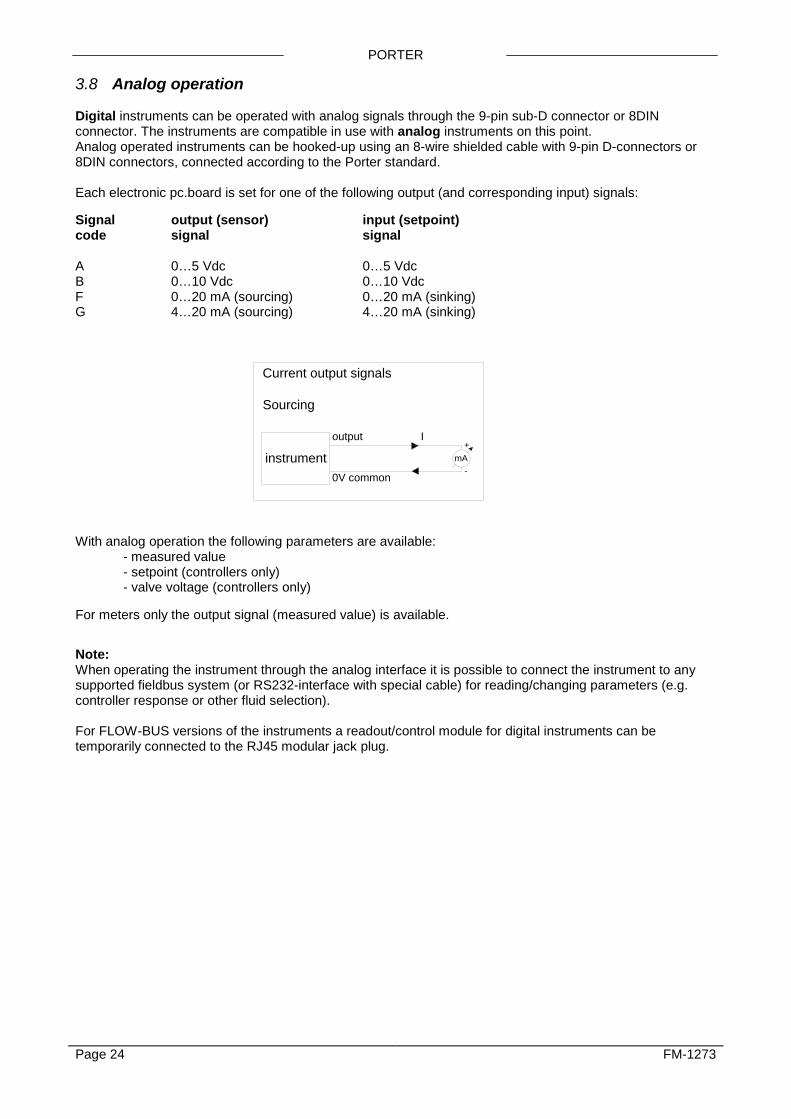
3.8 Analog operation Digital instruments can be operated with analog signals through the 9-pin sub-D connector or 8DIN connector. The instruments are compatible in use with analog instruments on this point. Analog operated instruments can be hooked-up using an 8-wire shielded cable with 9-pin D-connectors or 8DIN connectors, connected according to the Porter standard. Each electronic pc.board is set for one of the following output (and corresponding input) signals: Signal output (sensor) input (setpoint) code signal signal A 0…5 Vdc 0…5 Vdc B 0…10 Vdc 0…10 Vdc F 0…20 mA (sourcing) 0…20 mA (sinking) G 4…20 mA (sourcing) 4…20 mA (sinking)
With analog operation the following parameters are available:
- measured value - setpoint (controllers only) - valve voltage (controllers only)
For meters only the output signal (measured value) is available. Note: When operating the instrument through the analog interface it is possible to connect the instrument to any supported fieldbus system (or RS232-interface with special cable) for reading/changing parameters (e.g. controller response or other fluid selection). For FLOW-BUS versions of the instruments a readout/control module for digital instruments can be temporarily connected to the RJ45 modular jack plug.
Page 24 FM-1273

PORTER
3.9 BUS / digital operation Operation via fieldbus reduces the amount of cables to build a system of several instruments and offers more parameter values to be monitored / changed by the user. See instruction manual: operating digital mass flow / pressure instruments for more details (document number FM-1245). Operation by means of a fieldbus adds a lot of extra features (compared to analog operation) to the instruments. Such as:
- setpoint slope (ramp function on setpoint for smooth control) - 8 selectable fluids (calibration settings for high accuracy) - direct reading at readout/control module or host computer - testing and self diagnosis - response alarm (|setpoint-measure| too high for too long time) - several control/setpoint modes (e.g. purge/close valve) - master/slave modes for ratio control (FLOW-BUS only) - identification (serialnumber, modelnumber, device type, user tag) - adjustable minimal and maximal alarm limits - (batch) counter - adjustable response time for controller when opening from zero - adjustable response time for normal control - adjustable response time for stable control (| (setpoint-measure) | < 2%)
Note: Special RS232 cable consists of a T-part with 1 male and 1 female sub-D 9 connector / 8DIN connector on one instrument-side and a normal female sub-D 9 connector on the side of the computer. See hook-up diagram for the correct RS232 cable which should be used. Hook-up diagrams are available on the FM-1271 Software and Documentation CD. By means of this cable it is possible to offer RS232 communication and still be able to connect the power-supply and analog interface through the (analog) sub-D 9 connector / 8DIN connector. RS232 communication can be used for either: • Uploading new firmware by means of a special program (for trained Porter personnel only) • Servicing your instrument using Porter-service programs (for trained Porter personnel only) • Operating your instrument using FLOWDDE, FLOWB32.DLL or RS232-ASCII protocol (end user) Refer to manual FM-1249, for details on RS232 communication.
Page 25 FM-1273
PORTER
4 Maintenance 4.1 General With normal use, no routine maintenance is required to be performed on the meters or controllers. Units may be flushed with clean, dry inert gas. For further information contact supplier or factory. 4.2 Gas flow sensor The gas flow sensor is constructed in such a way that for a change in range, the laminar flow element can be replaced. It is not recommended for the user to disassemble the instrument other than for removing the laminar flow element for inspection, or range changing only. After replacing the laminar flow element it becomes necessary to recalibrate the flow meter. When doing so proceed according to a suitable calibration procedure. Depending on the model number laminar flow elements can be ordered separately. 4.3 Pressure sensor It is not recommended for the user to disassemble the pressure sensor, because the thin metal membrane is very delicate and can be damaged. 4.4 Controllers All sensor types can be combined with a control valve to be operated together as a flow controller (control loop). Controller systems are either available as separate units: a sensor and a control valve, or as an integrated unit. If applicable contact factory for maintenance procedures. 4.5 Control valves Control valves cannot be used for shut-off and/or on-off applications. Pressure surges, as may occur during system pressurisation or deflation must be avoided.
4.5.1 Solenoid valves Consult factory for maintenance.
4.5.2 VPC valve The VPC (Variable Pressure Compensation) valve is designed to cope with extremely varying process conditions on either upstream or downstream side of the valve or a combination of these. ∆p can vary over a wide range. The basic control valve is a direct operated solenoid control valve. The VPC design has been patented. For orifice selection and maintenance consult the factory.
4.5.3 Pilot operated valve This control valve is an indirect control valve, consisting of a spring loaded membrane / orifice system which is positioned by a solenoid operated direct control pilot valve. The two devices are integrated in one block. Consult factory for maintenance. Note: When pressure testing a system incorporating a pilot operated control valve, a special procedure must be followed in order to prevent damage to the valve. In such cases it is necessary to contact the factory prior to doing this.
Page 26 FM-1273
PORTER
4.5.4 Bellows valve These valves are suited for low pressure or vacuum applications. Preferably this model should not be disassembled by the user. Porter Instruments strongly advises to mount the bellows valves in an upright position. 4.6 Calibration procedure All instruments are factory calibrated. For re-calibration or re-ranging contact supplier or factory.
Page 27 FM-1273
PORTER
5 Digital instrument See document number FM-1245 for detailed description of the Digital instrument. This document is available as PDF on the FM-1271 Software and Documentation CD.
6 Interface description For a description of the available interfaces see document numbers: FM-1246 for FLOW-BUS FM-1247 for PROFIBUS-DP FM-1248 for DeviceNet FM-1249 for RS232 FM-1250 for Modbus FM-1253 for EtherCAT® These documents are available on the FM-1271 Software and Documentation CD or from the factory.
7 TROUBLESHOOTING 7.1 General For a correct analysis of the proper operation of a flow/pressure meter or controller it is recommended to remove the unit from the process line and check it without applying fluid supply pressure. In case the unit is dirty, this can be ascertained immediately by loosening the compression type couplings and, if applicable the flange on the inlet side. Porter does not recommend opening the housing. Energizing or de-energizing of the instrument and monitoring the LEDs helps indicate whether there is an electronic failure. After that, fluid pressure is to be applied in order to check behaviour. If there should be suspicion of leakage, do not check for bubbles with a leak detection liquid as this may lead to a short-circuit in the sensor or pc.board.
Page 28 FM-1273
PORTER
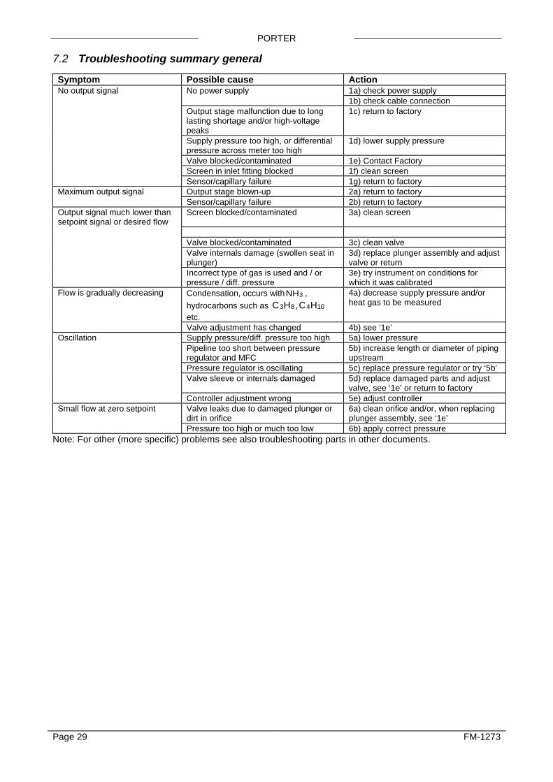
7.2 Troubleshooting summary general Symptom Possible cause Action No output signal No power supply 1a) check power supply 1b) check cable connection Output stage malfunction due to long
lasting shortage and/or high-voltage peaks
1c) return to factory
Supply pressure too high, or differential pressure across meter too high
1d) lower supply pressure
Valve blocked/contaminated 1e) Contact Factory Screen in inlet fitting blocked 1f) clean screen Sensor/capillary failure 1g) return to factory Maximum output signal Output stage blown-up 2a) return to factory Sensor/capillary failure 2b) return to factory Output signal much lower than setpoint signal or desired flow
Screen blocked/contaminated 3a) clean screen
Valve blocked/contaminated 3c) clean valve Valve internals damage (swollen seat in
plunger) 3d) replace plunger assembly and adjust valve or return
Incorrect type of gas is used and / or pressure / diff. pressure
3e) try instrument on conditions for which it was calibrated
Flow is gradually decreasing Condensation, occurs withNH3 , hydrocarbons such as C H ,C H3 8 4 10etc.
4a) decrease supply pressure and/or heat gas to be measured
Valve adjustment has changed 4b) see ‘1e’ Oscillation Supply pressure/diff. pressure too high 5a) lower pressure Pipeline too short between pressure
regulator and MFC 5b) increase length or diameter of piping upstream
Pressure regulator is oscillating 5c) replace pressure regulator or try ‘5b’ Valve sleeve or internals damaged 5d) replace damaged parts and adjust
valve, see ‘1e’ or return to factory Controller adjustment wrong 5e) adjust controller Small flow at zero setpoint Valve leaks due to damaged plunger or
dirt in orifice 6a) clean orifice and/or, when replacing plunger assembly, see ‘1e’
Pressure too high or much too low 6b) apply correct pressure Note: For other (more specific) problems see also troubleshooting parts in other documents.
Page 29 FM-1273

PORTER
8 POLICIES AND CERTIFICATE OF WARRANTY 8.1 Policies 8.2 Prices All prices are F.O.B. Hatfield, PA, and subject to change without notice. All merchandise will be invoiced at prices in effect at time of shipment. Prices do not include insurance, freight, taxes or special handling. These charges, if applicable, will be shown separately on invoice. Minimum order $30.00. 8.3 Payment Terms Net 30 days after invoice date. All invoices past due are subject to a finance charge of 1½% per month (18% annual rate). 8.4 Shipments Shipment of merchandise shall at times be subject to credit approval and will be contingent upon fires, accidents, emergencies, acts of God or any other causes which are beyond Porter Instrument control. Specifications and dimensions subject to change.
8.5 Cancellations No cancellations will be accepted on non-standard or special merchandise, except by payment of full purchase price. If buyer requests cancellation of any order or part thereof, and is agreed to by Porter Instrument in writing, buyer will be subject to cancellation charges to cover the cost of material and/or fabrication incurred by Porter Instrument to date of cancellation. 8.6 Changes of Order
A minimum of 90 days notice is required on all changes to orders and will be subject to rescheduling as a new order at Porter Instrument discretion. 8.7 Returns
No returns will be accepted unless authorized in writing by Porter Instrument and accompanied by a properly completed Returned Goods Authorization. All returns are subject to restocking and possible rework charges to be determined by Porter Instrument
8.8 Certificate of Warranty
THIS WARRANTY IS GIVEN IN PLACE OF ALL OTHER WARRANTIES, EXPRESS OR IMPLIED, OF MERCHANTABILITY, FITNESS FOR A PARTICULAR PURPOSE, OR OTHERWISE. NO PROMISE OR STATEMENT MADE BY ANY REPRESENTATIVE OR AUTHORIZED DEALER OF PORTER INSTRUMENT SHALL CONSTITUTE A WARRANTY BY PORTER INSTRUMENT. PORTER INSTRUMENT ASSUMES NO LIABILITY FOR USE OF THIS EQUIPMENT. Porter Instrument warrants this equipment to be free from defects in workmanship and materials, when used in accordance with applicable specifications and with appropriate maintenance, for one (1) year from date of delivery to the customer, unless otherwise specified in writing. Equipment which malfunctions may be returned, shipment prepaid, to Porter Instrument for test and evaluation. Equipment determined to be defective and in warranty will be repaired or replaced at no charge to the customer. Equipment out of warranty will be evaluated, and if the equipment does not meet original specifications and calibration, the customer will be notified of the costs before proceeding with repair or replacement. Repaired equipment will be warranted ninety (90) days from date of delivery to the customer or for the balance of the original warranty, whichever is longer. Failures due to shipping damage, accident, misuse, improper mechanical or electrical installation or operation, or internal clogging or corrosion due to use of contaminated fluids or inadequate system purging are excluded from warranty coverage. Porter Instrument obligation for breach of this warranty, or for negligence or otherwise, shall be strictly and exclusively limited to the repair or replacement of the equipment. This warranty shall be void as to any equipment on which the serial number, if applicable, has been altered, defaced, or removed. Porter Instrument shall under no circumstances be liable for incidental or consequential damages. No other promise or statement about the equipment by any representative or authorized dealer of Porter Instrument shall constitute a warranty by Porter Instrument or give rise to any liability or obligation of Porter Instrument
Page 30 FM-1273

Appendix 1
Gas Conversion Table

GAS CONVERSION FACTOR
Nr.: Name: Symbol Density n g l[ / ] 0°C, 1 atm.
Heat capacity* c cal cal g Kp [ / . ]20°C, 1 atm.
Conversion factor 20°C, 1 atm.
1 2 3 4 5
Acetylene (Ethyne) Air Allene (Propadiene) Ammonia Argon
C2H2 Air C3H4 NH3 Ar
1.172 1.293 1.832 0.7693 1.784
0.438 0.241 0.392 0.524 0.125
0.61 1.00 0.43 0.77 1.40
6 7 8 9 10
Arsine Boron trichloride Boron trifluoride Bromine pentafluoride Butadiene (1,3-)
AsH3 BCl3 BF3 BrF5 C4H6
3.524 5.227 3.044 7.803 2.504
0.133 0.136 0.188 0.156 0.405
0.66 0.44 0.54 0.26 0.31
11 12 13 14 15
Butane Butene (1-) Butene (2-) (Cis) Butene (2-) (Trans) Carbonylfluoride
C4H10 C4H8 C4H8 C4H8 COF2
2.705 2.581 2.503 2.503 2.983
0.457 0.415 0.387 0.421 0.194
0.25 0.29 0.32 0.30 0.54
16 17 18 19 20
Carbonylsulfide Carbon dioxide Carbon disulfide Carbon monoxide Chlorine
COS CO2 CS2 CO Cl2
2.724 1.977 3.397 1.25 3.218
0.175 0.213 0.152 0.249 0.118
0.65 0.74 0.60 1.00 0.82
21 22 23 24 25
Chlorine trifluoride Cyanogen Cyanogen chloride Cyclopropane Deuterium
ClF3 C2N2 ClCN C3H6 D2
4.125 2.376 2.743 1.919 0.1798
0.188 0.275 0.185 0.374 1.73
0.40 0.48 0.61 0.43 1.00
26 27 28 29 30
Diborane Dibromo difluoromethane Dichlorosilane Dimethylamine Dimethylpropane (2,2-)
B2H6 Br2CF2 SiH2Cl2 C2H6NH C5H12
1.248 9.361 4.506 2.011 3.219
0.577 0.17 0.17 0.417 0.462
0.43 0.20 0.41 0.37 0.21
31 32 33 34 35
Dimethylether Disilane Ethane Ethylene (Ethene) Ethylene oxide
C2H6O Si2H6 C2H6 C2H4 C2H4O
2.105 2.857 1.355 1.261 1.965
0.378 0.352 0.468 0.414 0.303
0.39 0.31 0.49 0.60 0.52
36 37 38 39 40
Ethylacetylene (1-Butyne) Ethylchloride Fluorine Freon-11 Freon-113
C4H6 C2H5Cl F2 CCl3F C2Cl3F3
2.413 2.878 1.696 6.129 8.36
0.401 0.263 0.201 0.145 0.174
0.32 0.41 0.91 0.35 0.21
41 42 43 44 45
Freon-1132A Freon-114 Freon-115 Freon-116 Freon-12
C2H2F2 C2Cl2F4 C2ClF5 C2F6 CCl2F2
2.889 7.626 7.092 6.251 5.547
0.244 0.177 0.182 0.2 0.153
0.44 0.23 0.24 0.25 0.37
46 47 48 49 50
Freon-13 Freon-13B1 Freon-14 Freon-21 Freon-22
CClF3 CBrF3 CF4 CHCl2F CHClF2
4.72 6.768 3.946 4.592 3.936
0.165 0.12 0.18 0.154 0.168
0.40 0.38 0.44 0.44 0.47
51 52 53
Freon-23 Freon-C318 Germane
CHF3 C4F8 GeH4
3.156 9.372 3.45
0.191 0.222 0.16
0.52 0.15 0.56
* cp - cal (T,p) = cp (T + 50°C, p)
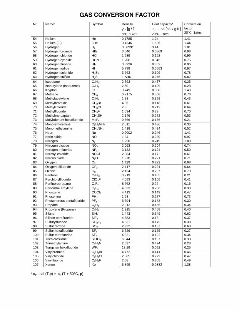
GAS CONVERSION FACTOR
Nr.: Name: Symbol Density n g l[ / ] 0°C, 1 atm.
Heat capacity* c cal cal g Kp [ / . ]20°C, 1atm.
Conversion factor 20°C, 1atm.
54 55 56 57 58
Helium Helium (3-) Hydrogen Hydrogen bromide Hydrogen chloride
He 3He H2 HBr HCl
0.1785 0.1346 0.08991 3.646 1.639
1.24 1.606 3.44 0.0869 0.192
1.41 1.44 1.01 0.98 0.99
59 60 61 62 63
Hydrogen cyanide Hydrogen fluoride Hydrogen iodide Hydrogen selenide Hydrogen sulfide
HCN HF HI H2Se H2S
1.206 0.8926 5.799 3.663 1.536
0.345 0.362 0.0553 0.109 0.246
0.75 0.96 0.97 0.78 0.82
64 65 66 67 68
Isobutane Isobutylene (Isobutene) Krypton Methane Methylacetylene
C4H10 C4H8 Kr CH4 C3H4
2.693 2.60 3.749 0.7175 1.83
0.457 0.429 0.058 0.568 0.399
0.25 0.28 1.43 0.76 0.43
69 70 71 72 73
Methylbromide Methylchloride Methylfluoride Methylmercaptan Molybdenum hexafluoride
CH3Br CH3Cl CH3F CH3SH MoF6
4.35 2.3 1.534 2.146 9.366
0.118 0.212 0.29 0.272 0.156
0.61 0.64 0.70 0.53 0.21
74 75 76 77 78
Mono-ethylamine Monomethylamine Neon Nitric oxide Nitrogen
C2H5NH2 CH3NH2 Ne NO N2
2.011 1.419 0.9002 1.34 1.250
0.436 0.424 0.246 0.239 0.249
0.36 0.52 1.41 0.97 1.00
79 80 81 82 83
Nitrogen dioxide Nitrogen trifluoride Nitrosyl chloride Nitrous oxide Oxygen
NO2 NF3 NOCl N2O O2
2.053 3.182 2.984 1.978 1.429
0.204 0.194 0.17 0.221 0.222
0.74 0.50 0.61 0.71 0.98
84 85 86 87 88
Oxygen difluoride Ozone Pentane Perchlorylfluoride Perfluoropropane
OF2 O3 C5H12 ClO3F C3F8
2.417 2.154 3.219 4.653 8.662
0.201 0.207 0.455 0.165 0.22
0.64 0.70 0.21 0.41 0.16
89 90 91 92 93
Performa- ethylene Phosgene Phosphine Phosphorous pentafluoride Propane
C2F4 COCl2 PH3 PF5 C3H8
4.523 4.413 1.53 5.694 2.012
0.206 0.149 0.277 0.183 0.456
0.33 0.47 0.73 0.30 0.34
94 95 96 97 98
Propylene (Propene) Silane Silicon tetrafluoride Sulfurylfluoride Sulfur dioxide
C3H6 SiH4 SiF4 SO2F2 SO2
1.915 1.443 4.683 4.631 2.922
0.408 0.349 0.18 0.175 0.157
0.40 0.62 0.37 0.38 0.68
99 100 101 102 103
Sulfur hexafluoride Sulfur tetrafluoride Trichlorosilane Trimethylamine Tungsten hexafluoride
SF6 SF4 SiHCl3 C3H9N WF6
6.626 4.821 6.044 2.637 13.29
0.175 0.192 0.157 0.424 0.092
0.27 0.34 0.33 0.28 0.25
104 105 106 107
Vinylbromide Vinylchloride Vinylfluoride Xenon
C2H3Br C2H3Cl C2H3F Xe
4.772 2.865 2.08 5.899
0.141 0.229 0.305 0.0382
0.46 0.47 0.49 1.38
* cp - cal (T,p) = cp (T + 50°C, p)

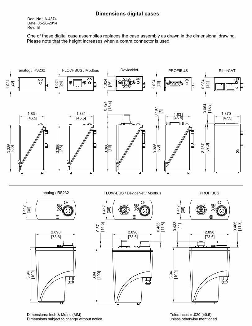
Appendix 2
Dimensions
Digital Cases