GENERAL INFORMATION OVERVIEW - Creating Dynamic Motor ...
18
January 2020 www.nidec-motor.com Nidec Motor Corporation I-2 † All marks shown within this document are properties of their respective owners. GENERAL INFORMATION IMPORTANT INFORMATION N idec Motor Corporation has made every effort to ensure the integrity of the contents of this catalog. However, Nidec Motor Corporation cannot accept responsibility for errors that may have been caused by changing model/catalog numbers, or for typographical or clerical errors in the preparation of this catalog. The motor data and dimensions are provided for reference only. Certified dimensions and performance data will be furnished upon request. Prices are subject to change without notification. Nidec Motor Corporation does not assume responsibility for the selection, use, or maintenance of any product. Responsibility for the proper selection, use and maintenance of any product within this cata- log remains solely with the purchaser and end-user. The contents of this publication are presented for informational purposes only, and while every effort has been made to ensure their accuracy, except for Nidec Motor Corporation’s standard Limited War- ranty stated herein, they are not to be constructed as warranties or guarantees, expressed or implied, regarding the products described herein or their use or applicability. Nidec Motor Corporation reserves the right to modify or improve the designs or specifications of such products at any time without notice. The following is a list of Nidec Motor Corporation’s U.S. trademarks for products and services in this catalog. The trademarks followed by the ® symbol are registered with the U.S. Patent and Trademark Office. ALLGUARD ® HOLLOSHAFT ® THERMA SENTRY ® VARIDYNE ® CORRO-DUTY ® INVERTER GRADE ® TITAN ® EVERSEAL™ HOSTILE DUTY ® SNOWMASTER TM U.S. MOTORS ® INSULIFE™ PRODUCT OVERVIEW
Transcript of GENERAL INFORMATION OVERVIEW - Creating Dynamic Motor ...
January 2020www.nidec-motor.com Nidec Motor Corporation
I-2
† All marks shown within this document are properties of their respective owners.
GENERAL INFORMATION
IMPORTANT INFORMATION
Nidec Motor Corporation has made every effort to ensure the integrity of the contents of this catalog. However, Nidec Motor Corporation cannot accept responsibility for errors that may have been
caused by changing model/catalog numbers, or for typographical or clerical errors in the preparation of this catalog. The motor data and dimensions are provided for reference only. Certified dimensions and performance data will be furnished upon request. Prices are subject to change without notification.
Nidec Motor Corporation does not assume responsibility for the selection, use, or maintenance of any product. Responsibility for the proper selection, use and maintenance of any product within this cata-log remains solely with the purchaser and end-user.
The contents of this publication are presented for informational purposes only, and while every effort has been made to ensure their accuracy, except for Nidec Motor Corporation’s standard Limited War-ranty stated herein, they are not to be constructed as warranties or guarantees, expressed or implied, regarding the products described herein or their use or applicability. Nidec Motor Corporation reserves the right to modify or improve the designs or specifications of such products at any time without notice.
The following is a list of Nidec Motor Corporation’s U.S. trademarks for products and services in this catalog. The trademarks followed by the ® symbol are registered with the U.S. Patent and Trademark Office.
ALLGUARD ® HOLLOSHAFT ® THERMA SENTRY ® VARIDYNE ®
CORRO-DUTY ® INVERTER GRADE ® TITAN ® EVERSEAL™ HOSTILE DUTY ® SNOWMASTERTM U.S. MOTORS ® INSULIFE™
PRODUCTOVERVIEW
January 2020www.nidec-motor.com Nidec Motor Corporation
I-3
† All marks shown within this document are properties of their respective owners.
GENERAL INFORMATION FOR INTEGRAL HORSEPOWER (IHP) MOTORS ON VARIABLE FREQUENCY DRIVES (VFDS)
Variable Frequency Drives (VFD)A VFD is a type of controller used to vary the speed of an electric motor. The VFD takes a fixed AC voltage and frequency and allows it to be adjusted in order to get different speeds from the motor. Motor speed can be varied by changing the frequency of the input power waveform. The equation below shows how the frequency affects the speed of a three phase induction motor.
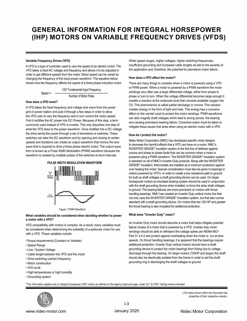
How does a VFD work?A VFD takes the fixed frequency and voltage sine wave from the power grid or power station and puts it through a few steps in order to allow the VFD user to vary the frequency and in turn control the motor speed.First it rectifies the AC power into DC Power. Because of this step, a term commonly used instead of VFD is inverter. This only describes one step of what the VFD does to the power waveform. Once rectified into a DC voltage the drive sends the power through a set of transistors or switches. These switches can take the DC waveform and by opening and closing at certain speeds and durations can create an output waveform that mimics the sine wave that is required to drive a three phase electric motor. The output wave form is known as a Pulse Width Modulation (PWM) waveform because the waveform is created by multiple pulses of the switches at short intervals.
What variables should be considered when deciding whether to power a motor with a VFD?VFD compatibility with motors is complex. As a result, many variables must be considered when determining the suitability of a particular motor for use with a VFD. These variables include:
•Torque requirements (Constant or Variable) • Speed Range • Line / System Voltage • Cable length between the VFD and the motor • Drive switching (carrier) frequency • Motor construction • VFD dv/dt • High temperatures or high humidity • Grounding system
Wider speed ranges, higher voltages, higher switching frequencies, insufficient grounding and increased cable lengths all add to the severity of the application and, therefore, the potential for premature motor failure.
HowdoesaVFDaffectthemotor?There are many things to consider when a motor is powered using a VFD or PWM power. When a motor is powered by a PWM waveform the motor windings very often see a large differential voltage, either from phase to phase or turn to turn. When the voltage differential becomes large enough it creates a reaction at the molecular level that converts available oxygen into O3. This phenomenon is called partial discharge or corona. This reaction creates energy in the form of light and heat. This energy has a corrosive effect on the varnish used to protect the motor windings. PWM waveforms can also magnify shaft voltages which lead to arcing across the bearing and causing premature bearing failure. Corrective action must be taken to mitigate these issues that arise when using an electric motor with a VFD.
How do I protect the motor?Nidec Motor Corporation (NMC) has developed specific motor designs to decrease the harmful effects that a VFD can have on a motor. NMC’s INVERTER GRADE® insulation system is the first line of defense against corona and phase to phase faults that can be common when a motor is powered using a PWM waveform. The INVERTER GRADE® insulation system is standard on all of NMC’s Inverter Duty products. Along with the INVERTER GRADE® insulation, thermostats are installed as a minimum protection against over heating the motor. Special consideration must also be given to bearings in motors powered by VFD’s. In order to create a low resistance path to ground for built up shaft voltages a shaft grounding device can be used. On larger horsepower motors an insulated bearing system should be used in conjunction with the shaft grounding device when installed, to force the stray shaft voltages to ground. The bearing failures are more prominent on motors with thrust handling bearings. NMC has created an Inverter Duty vertical motor line that not only uses the INVERTER GRADE® insulation system, but that also comes standard with a shaft grounding device. On motors that are 100 HP and greater the thrust bearing is also insulated for additional protection.
What does "Inverter Duty" mean?
An Inverter Duty motor should describe a motor that helps mitigate potential failure modes of a motor that is powered by a VFD. Inverter duty motor windings should be able to withstand the voltage spikes per NEMA MG1 Part 31.4.4.2 and protect against overheating when the motor is run at slow speeds. On thrust handling bearings, it is apparent that the bearings require additional protection. Inverter Duty vertical motors should have a shaft grounding device to protect the motor bearings from fluting due to voltage discharge through the bearing. On larger motors (100HP and larger) the shaft should also be electrically isolated from the frame in order to aid the shaft grounding ring in discharging the shaft voltages to ground.
*This information applies only to Integral Horsepower (IHP) motors as defined on the Agency Approval page, under UL®† & CSA®† listings where indicated.
Figure 1 PWM Waveform
PULSE WIDTH MODULATION WAVEFORM
Speed = 120* Fundamental Input Frequency
Number of Motor Poles
Line to
Neutral
Voltage
Line Current
January 2020www.nidec-motor.com Nidec Motor Corporation
I-4
† All marks shown within this document are properties of their respective owners.
MOTOR/ INVERTER COMPATIBILITY
Thermal Overloads and Single Phase MotorsMotors with thermal overloads installed may not operate properly on a VFD. The current carrying thermal overload is designed for sine wave power. Operation on a VFD may cause nuisance tripping or potentially not protect the motor as would be expected on line power. Thermostats or thermistors installed in the motor and connected properly to the VFD may provide suitable thermal overload protection when operating on a VFD. (consult codes for installation requirements)Single phase motors and other fractional horsepower ratings are not designed to be operated on a VFD. Within Nidec Motor Corporation standard products, all motors NEMA®† 48 frame (5.5” diameter) and smaller are not suitable for VFD applications. Three phase 56 and 143/145 frame applications should be noted on the catalog price page; or if in doubt ask an Nidec Motor Corporation technical representative for recommendations on compatibility with a VFD.
Slow Speed MotorsMotors with a base design of slower than six poles require special consideration regarding VFD sizing and minimizing harmonic distortion created at the motor terminals due to cable installation characteristics. Additional external PWM waveform filters and shielded motor cables designed for PWM power may be required to provide acceptable motor life. Harmonic distortion on the output waveform should be kept to a minimum level (less than 10%) mismatch impedence.
690V Applications Motors that are rated for 690VAC and that will be powered by 690VAC PWM VFDs require the use of an external filter to limit peak voltage spikes and the use of an INVERTER GRADE® motor. Where available, an alternative to using an output filter is to upgrade to a 2300V insulation system.
Low Voltage TITAN® MotorsWhen using 449 frame and larger motors on PWM type VFDs consider the use of an external filter and shielded motor cables designed for PWM power to minimize harmonic distortion and peak voltages at the motor terminals. Harmonic distortion on the output waveform should be kept to a minimum level (less than 10%).
Bearing Currents Related to PWM WaveformsDue to the uniqueness of this condition occurring in the field, protection of the motor bearings from shaft currents caused by common mode voltages is not a standard feature on sine wave or Inverter Duty motor products, unless explicitly noted. Some installations may be prone to a voltage discharge condition through the motor bearings called Electrical Discharge Machining (EDM) or fluting. EDM damage is related to characteristics of the PWM waveform, and the VFD programming, and installation factors. Bearing EDM as a result of VFD waveform characteristics may be prevented by the installation of a shaft grounding device such as a brush or ring and/or correction of the installation characteristics causing the shaft voltage condition. Insulated bearing(s) may be required. VFD filters may be used if bearing fluting is to be mitigated.
Bearing Protection on Inverter Duty Vertical MotorsAll U.S. MOTORS® brand “Inverter Duty” vertical products have a shaft grounding system that allows damaging shaft currents a low resistance path to ground. Bearings on vertical motors fed by VFD power without this bearing Bearings on vertical motors fed by VFD power without this bearing protection are not covered under any warrantyprotection are not covered under any warranty. All other bearing failure is covered per NMC’s standard warranty. An electric motor repair shop approved to service U.S. MOTORS® brand motors must verify that the cause of the bearing failure was not due to EDM damage.
Multiple Motors on a Single VFD Special considerations are required when multiple motors are powered from a single VFD unit. Most VFD manufacturers can provide guidelines for proper motor thermal considerations and starting/stopping of motors. Cable runs from the VFD and each motor can create conditions that will cause extra stress on the motor winding. Filters may be required at the motor to provide maximum motor life.
Grounding and Cable Installation Guidelines Proper output winding and grounding practices can be instrumental in minimizing motor related failures caused by PWM waveform characteristics and installation factors. VFD manufacturers typically provide detailed guidelines on the proper grounding of the motor to the VFD and output cable routing. Cabling manufacturers provide recommended cable types for PWM installations and critical information concerning output wiring impedance and capacitance to ground. Vertical Motors on VFDs Vertical motors operated on VFD power present unique conditions that may require consideration by the user or installation engineer:
• Locked rotor and drive tripping caused by non-reversing-ratchet operation at low motor speeds. It is not recommended to operate motors at less than 1/4 of synchronous speed. If slow speeds are required contact NMC engineering.
• Unexpected / unacceptable system vibration and or noise levels caused by the torque pulsation characteristics of the PWM waveform, a system critical frequency falling inside the variable speed range of the process or the added harmonic content of the PWM waveform exciting a system component
• Application related problems related to the controlled acceleration/deceleration and torque of the motor on VFD power and the building of system pressure/ load.
• The impact the reduction of pump speed has on the down thrust reflected to the pump motor and any minimum thrust requirements of the motor bearings
• Water hammer during shutdown damaging the non-reversing ratchet
Humidity and Non-operational Conditions The possible build-up of condensation inside the motor due to storage in an uncontrolled environment or non-operational periods in an installation, can lead to an increased rate of premature winding or bearing failures when combined with the stresses associated with PWM waveform characteristics. Moisture and condensation in and on the motor winding over time can provide tracking paths to ground, lower the resistance of the motor winding to ground, and lower the Corona Inception Voltage (CIV)level of the winding. Proper storage and maintenance guidelines are important to minimize the potential of premature failures. Space heaters or trickle voltage heating methods are the common methods for drying out a winding that has low resistance readings. Damage caused by these factors are not covered by the limited warranty provided for the motor unless appropriate heating methods are properly utilized during non-operational periods and prior to motor start-up.
NEMA®† Application Guide for AC Adjustable Speed Drive Systems: http://www.nema.org/stds/acadjustable.cfm#download
*This information applies only to Integral Horsepower (IHP) motors as defined on the Agency Approval page, under UL®† & CSA®† listings where indicated.
January 2020www.nidec-motor.com Nidec Motor Corporation
I-5
† All marks shown within this document are properties of their respective owners.
WARRANTY GUIDELINES FOR INTEGRAL HORSEPOWER (IHP)* MOTORS ON VARIABLE FREQUENCY DRIVES
*This information applies only to Integral Horsepower (IHP) motors as defined on the Agency Approval page, under UL®† & CSA®† listings where indicated.
Warranty Guidelines
The information in the following section refers to the motor and drive application guidelines and limitations for warranty.
Hazardous Location Motors
Use of a variable frequency drive with the motors in this catalog, intended for use in hazardous locations, is only approved for Division1, Class I, Group D hazardous location motors with a T2B temperature code, with a limitation of 2:1 constant torque or 10:1 variable torque output. No other stock hazardous location motors are inherently suitable for operation with a variable frequency drive. If other requirements are needed, including non-listed Division 2, please contact your Nidec Motor Corporation territory manager to conduct an engineering inquiry.
575 Volt Motors
575 volt motors can be applied on Inverters when output filters are used. Contact the drive manufacturer for filter selection and installation requirements.
Applying INVERTER GRADE® Insulated Motors on Variable Frequency Drives (2, 4, 6 pole)
The products within this catalog labeled “Inverter Duty” or “Vector Duty” are considered INVERTER GRADE® insulated motors. INVERTER GRADE® motors exceed the NEMA®† MG-1 Part 31 standard. Nidec Motor Corporation provides a three-year limited warranty on all NEMA®† frame INVERTER GRADE® insulated motors and allows long cable runs between the motor and the VFD (limited to 400 feet without output filters). Cable distance can be further limited by hot and humid environments and VFD manufacturers cable limits. These motors may be appropriate for certain severe inverter applications or when the factors relating to the end use application are undefined (such as spares).
Nidec Motor Corporation’s U.S. Motors® brand is available in the following INVERTER GRADE® insulated motors:
• Inverter Duty NEMA®† frame motors good for 10:1 Variable Torque & 5:1 Constant Torque, including Vertical Type RUSI
• Inverter Duty motors rated for 10:1 Constant Torque
• ACCU-Torq® and Vector Duty Motors with full torque to 0 Speed
• 841 Plus® NEMA®† Frame Motors
ApplyingPremiumEfficientmotors(thatdonothaveINVERTERGRADE® insulation) on Variable Frequency Drives (2, 4, 6 pole)
Premium efficient motors without INVERTER GRADE insulation meet minimum NEMA®† MG-1, Section IV, Part 31.4.4.2. These motors can be used with Variable Frequency Drives (with a reduced warranty period) under the following parameters:
• On NEMA®† frame motors, 10:1 speed rating on variable torque loads & 4:1 speed range on constant torque loads.
• On TITAN® frame motors, 10:1 speed rating on variable torque loads.
• On TITAN® frame motors, inquiry required for suitability on constant torque loads.
Cable distances are for reference only and can be further limited by hot and
humid environments (refer to Table 1). Refer to specific VFD manufacturers cable limits. Refer to the Motor/ Inverter Compatibility page for special consideration of vertical motor bearings.
WarrantyPeriodClarificationsandExceptionsStandardEnergyEfficientExclusion
Applying Standard & Energy Efficient Motors on Variable Frequency Drives is not recommended. VFD related failures on standard and energy efficient motors will not be covered under warranty.
Vertical Motor Windings Premium efficient vertical motors without INVERTER GRADE® insulation that are installed using the criteria described in this document and applied in the correct applications shall have a warranty while powered by a VFD for 12 months from date of installation or 18 months from date of manufacturing whichever comes first. See limited warranty page for horizontal motor warranty periods.
Bearing Exclusion for Thrust Handling Bearings Bearings used in premium efficient vertical motors, and all thrust handling bearings, that are powered by VFDs without shaft grounding devices or insulated bearings (when required) will not be covered under any warranty for damages caused from being powered by a VFD. All other bearing failure is covered per NMC’s standard warranty. An electric motor repair shop approved to service U.S. MOTORS® brand motors must verify that the cause of the bearing failure was not due to Electrical Discharge Machining.
Medium Voltage and Slow Speed Considerations Motors that are rated above 700 VAC or that are eight pole and slower require special consideration and installation and are not covered under the warranty guidelines in this document. Motors that are rated above 700VAC have special cable length and voltage differential issues that are specific to the VFD type and manufacture. The motor construction and cost may vary dramatically depending on the VFD topology and construction. Contact your NMC representative with VFD manufacturer name and model type for application and motor construction considerations. Motors that are designed eight pole and slower also require special installation and filters per the drive manufacturer.
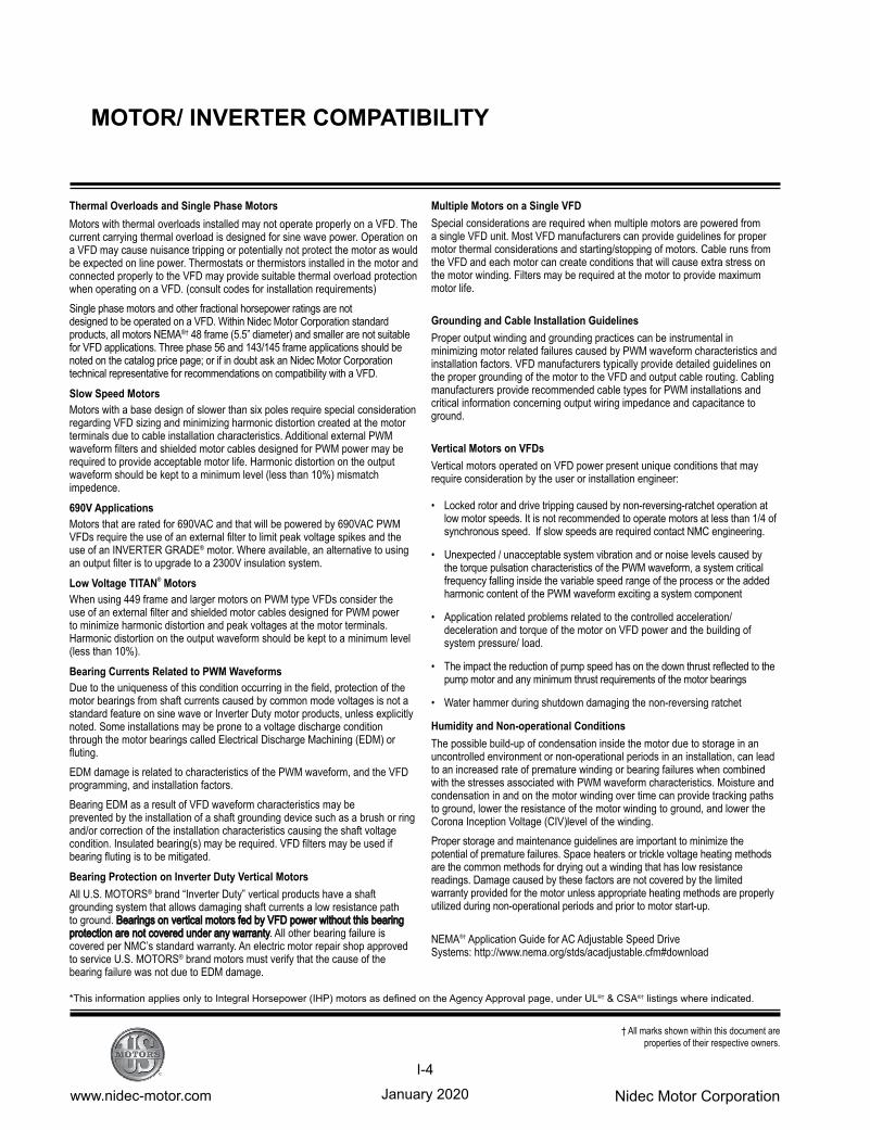
Table 1 - Cable Distances
Maximum Cable Distance VFD to Motor
Switching Frequency 460 Volt 230 Volt 380 Volt
3 Khz 127 ft 400 ft 218 ft
6 Khz 90 ft 307 ft 154 ft
9 Khz 73 ft 251 ft 126 ft
12 Khz 64 ft 217 ft 109 ft
15 Khz 57 ft 194 ft 98 ft
20 Khz 49 ft 168 ft 85 ft
January 2020www.nidec-motor.com Nidec Motor Corporation
I-6
† All marks shown within this document are properties of their respective owners.
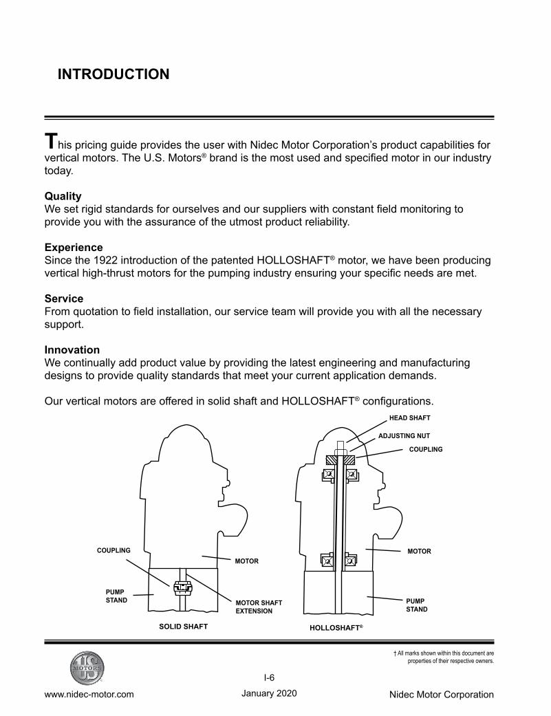
COUPLING
PUMPSTAND
SOLID SHAFT
MOTOR SHAFTEXTENSION
MOTOR
HOLLOSHAFT
PUMPSTAND
MOTOR
COUPLING
ADJUSTING NUT
HEAD SHAFT
INTRODUCTION
This pricing guide provides the user with Nidec Motor Corporation’s product capabilities for vertical motors. The U.S. Motors® brand is the most used and specified motor in our industry today.
QualityWe set rigid standards for ourselves and our suppliers with constant field monitoring to provide you with the assurance of the utmost product reliability.
ExperienceSince the 1922 introduction of the patented HOLLOSHAFT® motor, we have been producing vertical high-thrust motors for the pumping industry ensuring your specific needs are met.
ServiceFrom quotation to field installation, our service team will provide you with all the necessary support.
InnovationWe continually add product value by providing the latest engineering and manufacturing designs to provide quality standards that meet your current application demands.
Our vertical motors are offered in solid shaft and HOLLOSHAFT® configurations.
HOLLOSHAFT®SOLID SHAFT
January 2020www.nidec-motor.com Nidec Motor Corporation
I-7
† All marks shown within this document are properties of their respective owners.
OUR MOTORS
Introduced in 1922, U.S. Motors® brand vertical HOLLOSHAFT® motor was developed to meet the specific needs of the vertical turbine pump industry. With the pump shaft extended through the hollow shaft, adjustment can be made by a nut threaded on the shaft at the accessible top portion of the motor. This adjustment is required to lift the impellers and give a running clearance with the pump casing. The stretch of several hundred feet of shafting may require a lift at the top of the well, and the impeller at the bottom must be positioned within a fraction of an inch.
The drive coupling also provides a solution to the problem of power reversal. The pump shaft is usually composed of many lengths joined by screw thread couplings. A power reversal would unscrew the joints, causing the shaft to lengthen and buckle or break. The self-release coupling lifts out of its engagement position and prevents this problem.
In addition to normal induction motor classifications, the vertical motor is classified by thrust. Thrust is the sum of the axial forces of the weight of the pump and lineshaft and the dynamic forces of the pump to lift the liquid to the surface. NEMA does not specifically define thrust ratings for motors, but each manufacturer will define thrust ratings for their product rating. 100 percent high thrust, 175 percent high thrust and 300 percent high thrust are common.
Normal-thrust motors are used in general applications where there is very low or no external thrust applied to the motor bearing. It is often a footless horizontal motor with a “P” flange (the “P” flange mounting for the vertical motor).
In-line thrust, sometime called medium thrust, is a definite purpose motor. The pump impellers are mounted directly on the motor shaft. Since the pump impeller performance depends on close tolerance with the pump housing, the motor shaft and flange round-out tolerances must also be tighter than normal. The thrust bearing is usually located at the bottom rather than the top, as in high-thrust construction. This keeps the motor rotor’s thermal growth from affecting the impeller clearances.
Enclosures provide protection against specific environmental conditions. Our motors are available with Weather Protected I, Weather Protected II, Totally Enclosed and Hazardous Location enclosures.
January 2020www.nidec-motor.com Nidec Motor Corporation
I-8
† All marks shown within this document are properties of their respective owners.
MOTOR VARIETIES
Weather Protected Type I (WPI)
Open motors are constructed to minimize the en-trance of rain, snow and airborne particles. Our enclosures exceed NEMA®† requirements through built-in extra protection for rugged outdoor applica-tions. The ventilation system, available in all motor sizes, is designed to provide optimum cooling to the thrust bearing and electrical components.
Weather Protected Type II (WPII)
This NEMA®† enclosure offers maximum protec-tion against hostile outdoor atmospheres. The special ventilation system minimizes the entrance of high velocity air, moisture and airborne parti-cles into the cooling passages of the motor.
Totally Enclosed and Hazardous Location(TEFC/HAZARDOUS LOCATION)
Totally enclosed and Hazardous Location models are available with our non-sparking, non-reverse ratchet design for severe atmospheres where destructive dusts, vapors and other harmful substances are found. When Underwriters Lab-oratories’ approval is necessary, our Hazardous Location design is the answer. They are available in motor sizes through 700 horsepower.
CORRO-DUTY® cast-iron construction is also available with external corrosion-resistant paint and hardware for extremely harsh environments.
HOLLOSHAFT® motors page P-1 Solid Shaft motors page P-31WPI3–5000 Horsepower
HOLLOSHAFT® motorsSolid Shaft motorsWPII 150–5000 Horsepower
HOLLOSHAFT® motors page P-22Solid Shaft motors page P-53TEFC 3 – 2000 HorsepowerHAZARDOUS LOCATION 3-700 Horsepower
January 2020www.nidec-motor.com Nidec Motor Corporation
I-9
† All marks shown within this document are properties of their respective owners.
Normal Thrust
Normal-thrust motors are designed for use with pumps and other general industrial applications. Axial thrust is normally very low, while radial loads are generally higher. The thrust bearing is locked for thrust in either direction.Available in Open and Enclosed Designs
In-line Pump Motor
The in-line pump motor is specially designed and manufactured for long life in applications involving radial load due to suction variation and changes in pump capacity.Available in Enclosed and Hazardous Location Designs
Vertical Aerator Motor
A special CORRO-DUTY® treatment makes our motors unsurpassed for reliability in hostile environments, particularly those related to waste aeration. For severe applications, the CORRO-DUTY® vertical aerator to the municipal, pulp and paper, and petroleum and chemical industries, among others.
Solid Shaft motors page P-711–800 Horsepower
Solid Shaft motors page P-653–200 Horsepower
Solid Shaft motors page P-68TEFC5–200 Horsepower
MOTOR VARIETIES (continued)
January 2020www.nidec-motor.com Nidec Motor Corporation
I-10
† All marks shown within this document are properties of their respective owners.
CLASSIFICATIONS
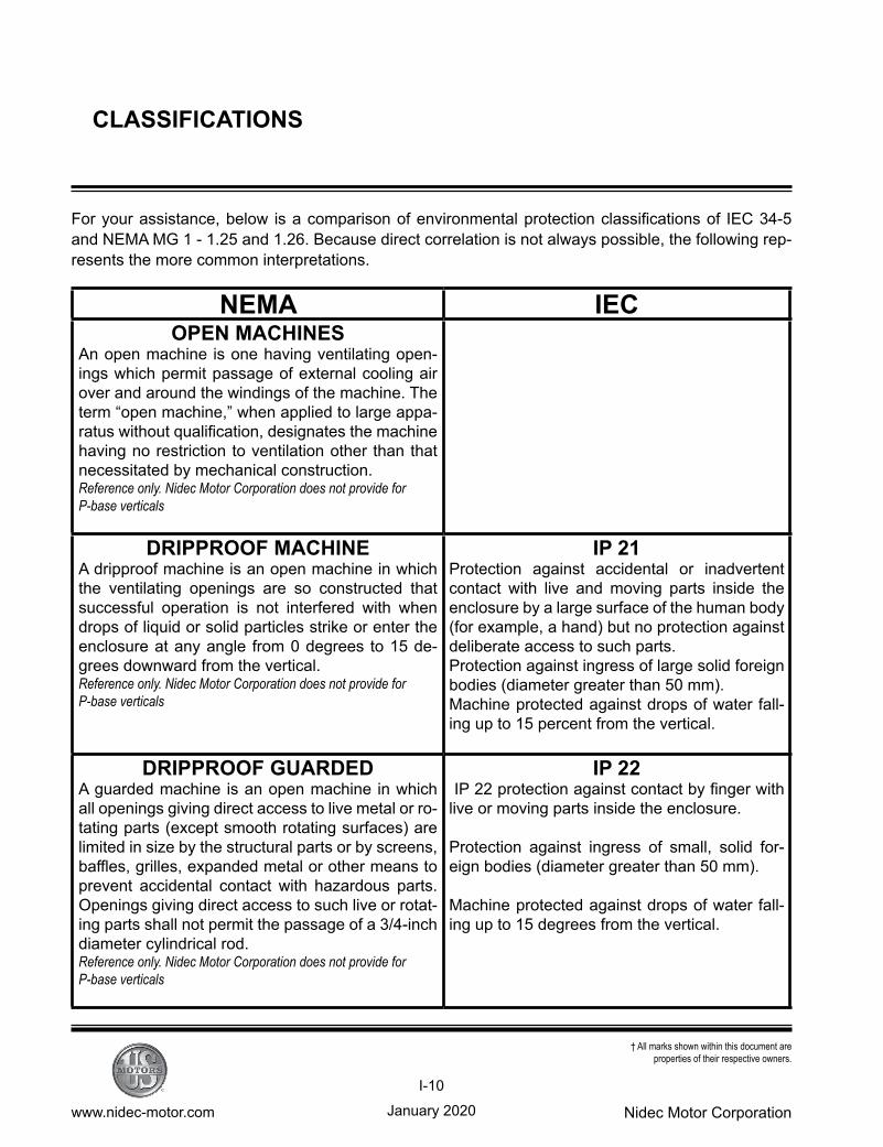
For your assistance, below is a comparison of environmental protection classifications of IEC 34-5 and NEMA MG 1 - 1.25 and 1.26. Because direct correlation is not always possible, the following rep-resents the more common interpretations.
NEMA IECOPEN MACHINES
An open machine is one having ventilating open-ings which permit passage of external cooling air over and around the windings of the machine. The term “open machine,” when applied to large appa-ratus without qualification, designates the machine having no restriction to ventilation other than that necessitated by mechanical construction.Reference only. Nidec Motor Corporation does not provide for P-base verticals
DRIPPROOF MACHINEA dripproof machine is an open machine in which the ventilating openings are so constructed that successful operation is not interfered with when drops of liquid or solid particles strike or enter the enclosure at any angle from 0 degrees to 15 de-grees downward from the vertical.Reference only. Nidec Motor Corporation does not provide for P-base verticals
IP 21Protection against accidental or inadvertent contact with live and moving parts inside the enclosure by a large surface of the human body (for example, a hand) but no protection against deliberate access to such parts.Protection against ingress of large solid foreign bodies (diameter greater than 50 mm).Machine protected against drops of water fall-ing up to 15 percent from the vertical.
DRIPPROOF GUARDEDA guarded machine is an open machine in which all openings giving direct access to live metal or ro-tating parts (except smooth rotating surfaces) are limited in size by the structural parts or by screens, baffles, grilles, expanded metal or other means to prevent accidental contact with hazardous parts. Openings giving direct access to such live or rotat-ing parts shall not permit the passage of a 3/4-inch diameter cylindrical rod.Reference only. Nidec Motor Corporation does not provide for P-base verticals
IP 22 IP 22 protection against contact by finger with live or moving parts inside the enclosure.
Protection against ingress of small, solid for-eign bodies (diameter greater than 50 mm).
Machine protected against drops of water fall-ing up to 15 degrees from the vertical.
January 2020www.nidec-motor.com Nidec Motor Corporation
I-11
† All marks shown within this document are properties of their respective owners.
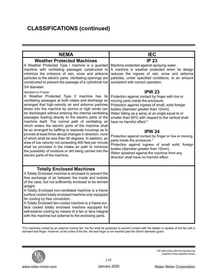
NEMA IECWeather Protected Machines
A Weather Protected Type I machine is a guarded machine with ventilating passages constructed to minimize the entrance of rain, snow and airborne particles to the electric parts. Ventilating openings are constructed to prevent the passage of a cylindrical rod 3/4 diameter.Standard on P-baseA Weather Protected Type II machine has its ventilating passages at both intake and discharge so arranged that high-velocity air and airborne particles blown into the machine by storms or high winds can be discharged without entering the internal ventilating passages leading directly to the electric parts of the machine itself. The normal path of ventilating air which enters the electric parts of the machine shall be so arranged by baffling or separate housings as to provide at least three abrupt changes in direction, none of which shall be less than 90 degrees. In addition, an area of low velocity not exceeding 600 feet per minute shall be provided in the intake air path to minimize the possibility of moisture or dirt being carried into the electric parts of the machine.
IP 23Machine protected against spraying water.A machine is weather protected when its design reduces the ingress of rain, snow and airborne particles, under specified conditions, to an amount consistent with correct operation.
IPW 23Protection against contact by finger with live or moving parts inside the enclosure.Protection against ingress of small, solid foreign bodies (diameter greater than 12mm). Water falling as a spray at an angle equal to or smaller than 600C with respect to the vertical shall have no harmful effect.*
IPW 24Protection against contact by finger or live or moving parts inside the enclosure.*Protection against ingress of small solid, foreign bodies (diameter greater than 12mm).Water splashed against the machine from any direction shall have no harmful effect.
Totally Enclosed MachinesA Totally Enclosed machine is enclosed to prevent the free exchange of air between the inside and outside of the case, but not sufficiently enclosed to be termed airtight.A Totally Enclosed non-ventilated machine is a frame surface cooled totally enclosed machine only equipped for cooling by free convection. A Totally Enclosed fan-cooled machine is a frame-sur-face cooled totally enclosed machine equipped for self-exterior cooling by means of a fan or fans integral with the machine but external to the enclosing parts.
*For machines cooled by an external cooling fan, the fan shall be protected to prevent contact with the blades or spokes of the fan with a standard test finger. However, at the outlet of the fan, the test finger is not inserted past the 50mm diameter guard.
CLASSIFICATIONS (continued)
January 2020www.nidec-motor.com Nidec Motor Corporation
I-12
† All marks shown within this document are properties of their respective owners.
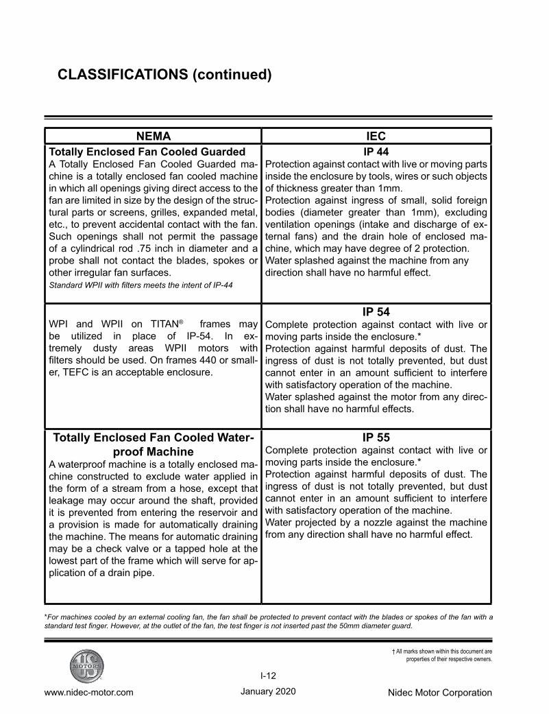
NEMA IECTotally Enclosed Fan Cooled GuardedA Totally Enclosed Fan Cooled Guarded ma-chine is a totally enclosed fan cooled machine in which all openings giving direct access to the fan are limited in size by the design of the struc-tural parts or screens, grilles, expanded metal, etc., to prevent accidental contact with the fan. Such openings shall not permit the passage of a cylindrical rod .75 inch in diameter and a probe shall not contact the blades, spokes or other irregular fan surfaces.Standard WPII with filters meets the intent of IP-44
IP 44Protection against contact with live or moving parts inside the enclosure by tools, wires or such objects of thickness greater than 1mm. Protection against ingress of small, solid foreign bodies (diameter greater than 1mm), excluding ventilation openings (intake and discharge of ex-ternal fans) and the drain hole of enclosed ma-chine, which may have degree of 2 protection.Water splashed against the machine from any direction shall have no harmful effect.
WPI and WPII on TITAN® frames may be utilized in place of IP-54. In ex-tremely dusty areas WPII motors with filters should be used. On frames 440 or small-er, TEFC is an acceptable enclosure.
IP 54Complete protection against contact with live or moving parts inside the enclosure.*Protection against harmful deposits of dust. The ingress of dust is not totally prevented, but dust cannot enter in an amount sufficient to interfere with satisfactory operation of the machine. Water splashed against the motor from any direc-tion shall have no harmful effects.
Totally Enclosed Fan Cooled Water-proof Machine
A waterproof machine is a totally enclosed ma-chine constructed to exclude water applied in the form of a stream from a hose, except that leakage may occur around the shaft, provided it is prevented from entering the reservoir and a provision is made for automatically draining the machine. The means for automatic draining may be a check valve or a tapped hole at the lowest part of the frame which will serve for ap-plication of a drain pipe.
IP 55Complete protection against contact with live or moving parts inside the enclosure.*Protection against harmful deposits of dust. The ingress of dust is not totally prevented, but dust cannot enter in an amount sufficient to interfere with satisfactory operation of the machine. Water projected by a nozzle against the machine from any direction shall have no harmful effect.
CLASSIFICATIONS (continued)
*For machines cooled by an external cooling fan, the fan shall be protected to prevent contact with the blades or spokes of the fan with a standard test finger. However, at the outlet of the fan, the test finger is not inserted past the 50mm diameter guard.
January 2020www.nidec-motor.com Nidec Motor Corporation
I-13
† All marks shown within this document are properties of their respective owners.
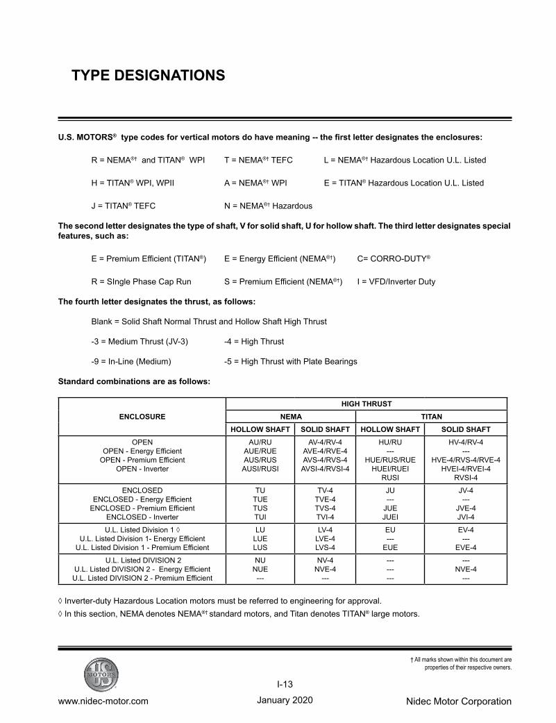
U.S. MOTORS® typecodesforverticalmotorsdohavemeaning--thefirstletterdesignatestheenclosures:
R = NEMA®† and TITAN® WPI T = NEMA®† TEFC L = NEMA®† Hazardous Location U.L. Listed
H = TITAN® WPI, WPII A = NEMA®† WPI E = TITAN® Hazardous Location U.L. Listed
J = TITAN® TEFC N = NEMA®† Hazardous
The second letter designates the type of shaft, V for solid shaft, U for hollow shaft. The third letter designates special features,suchas:
E = Premium Efficient (TITAN®) E = Energy Efficient (NEMA®†) C= CORRO-DUTY®
R = SIngle Phase Cap Run S = Premium Efficient (NEMA®†) I = VFD/Inverter Duty
Thefourthletterdesignatesthethrust,asfollows:
Blank = Solid Shaft Normal Thrust and Hollow Shaft High Thrust
-3 = Medium Thrust (JV-3) -4 = High Thrust
-9 = In-Line (Medium) -5 = High Thrust with Plate Bearings
Standardcombinationsareasfollows:
◊ Inverter-duty Hazardous Location motors must be referred to engineering for approval.◊ In this section, NEMA denotes NEMA®† standard motors, and Titan denotes TITAN® large motors.
ENCLOSUREHIGH THRUST
NEMA TITAN HOLLOW SHAFT SOLID SHAFT HOLLOW SHAFT SOLID SHAFT
OPENOPEN - Energy Efficient
OPEN - Premium EfficientOPEN - Inverter
AU/RUAUE/RUEAUS/RUSAUSI/RUSI
AV-4/RV-4AVE-4/RVE-4AVS-4/RVS-4AVSI-4/RVSI-4
HU/RU---
HUE/RUS/RUEHUEI/RUEI
RUSI
HV-4/RV-4---
HVE-4/RVS-4/RVE-4HVEI-4/RVEI-4
RVSI-4
ENCLOSEDENCLOSED - Energy Efficient
ENCLOSED - Premium EfficientENCLOSED - Inverter
TUTUETUSTUI
TV-4TVE-4TVS-4TVI-4
JU---
JUEJUEI
JV-4---
JVE-4JVI-4
U.L. Listed Division 1 ◊U.L. Listed Division 1- Energy Efficient
U.L. Listed Division 1 - Premium Efficient
LULUELUS
LV-4LVE-4LVS-4
EU---
EUE
EV-4---
EVE-4
U.L. Listed DIVISION 2 U.L. Listed DIVISION 2 - Energy EfficientU.L. Listed DIVISION 2 - Premium Efficient
NUNUE---
NV-4NVE-4
---
---------
---NVE-4
---
TYPE DESIGNATIONS
January 2020www.nidec-motor.com Nidec Motor Corporation
I-14
† All marks shown within this document are properties of their respective owners.
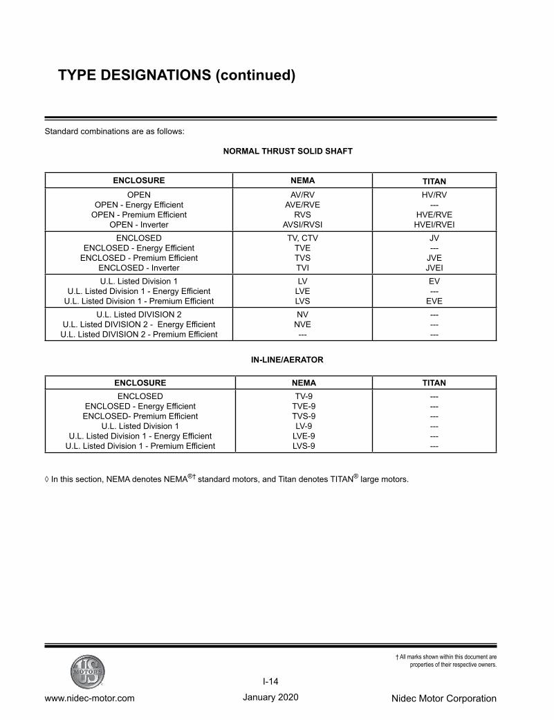
Standard combinations are as follows:
NORMAL THRUST SOLID SHAFT
IN-LINE/AERATOR
ENCLOSURE NEMA TITAN OPEN
OPEN - Energy EfficientOPEN - Premium Efficient
OPEN - Inverter
AV/RVAVE/RVE
RVSAVSI/RVSI
HV/RV---
HVE/RVEHVEI/RVEI
ENCLOSEDENCLOSED - Energy Efficient
ENCLOSED - Premium EfficientENCLOSED - Inverter
TV, CTVTVETVSTVI
JV---
JVEJVEI
U.L. Listed Division 1U.L. Listed Division 1 - Energy Efficient
U.L. Listed Division 1 - Premium Efficient
LVLVELVS
EV---
EVEU.L. Listed DIVISION 2
U.L. Listed DIVISION 2 - Energy EfficientU.L. Listed DIVISION 2 - Premium Efficient
NVNVE---
---------
ENCLOSURE NEMA TITANENCLOSED
ENCLOSED - Energy EfficientENCLOSED- Premium Efficient
U.L. Listed Division 1U.L. Listed Division 1 - Energy Efficient
U.L. Listed Division 1 - Premium Efficient
TV-9TVE-9TVS-9LV-9
LVE-9LVS-9
------------------
TYPE DESIGNATIONS (continued)
◊ In this section, NEMA denotes NEMA®† standard motors, and Titan denotes TITAN® large motors.
January 2020www.nidec-motor.com Nidec Motor Corporation
I-15
† All marks shown within this document are properties of their respective owners.
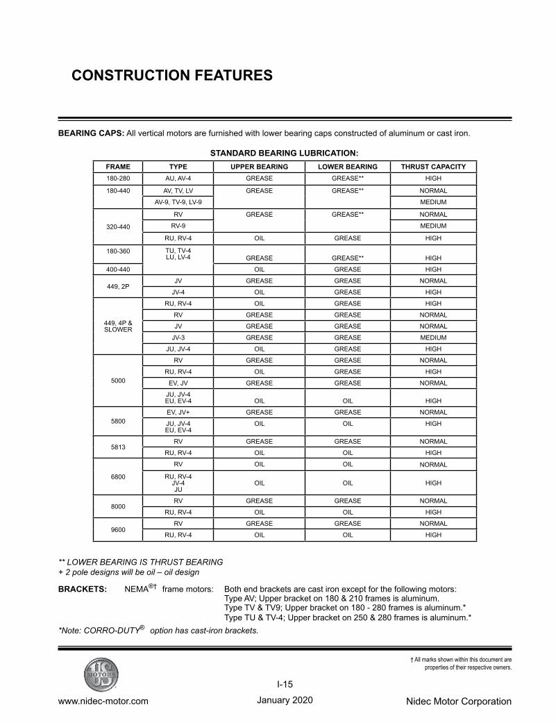
BEARINGCAPS: All vertical motors are furnished with lower bearing caps constructed of aluminum or cast iron.
STANDARDBEARINGLUBRICATION:
** LOWER BEARING IS THRUST BEARING+ 2 pole designs will be oil – oil design
BRACKETS: NEMA®† frame motors: Both end brackets are cast iron except for the following motors: Type AV; Upper bracket on 180 & 210 frames is aluminum. Type TV & TV9; Upper bracket on 180 - 280 frames is aluminum.* Type TU & TV-4; Upper bracket on 250 & 280 frames is aluminum.**Note: CORRO-DUTY® option has cast-iron brackets.
FRAME TYPE UPPER BEARING LOWER BEARING THRUST CAPACITY180-280 AU, AV-4 GREASE GREASE** HIGH
180-440 AV, TV, LV GREASE GREASE** NORMAL
AV-9, TV-9, LV-9 MEDIUM
320-440
RV GREASE GREASE** NORMAL
RV-9 MEDIUM
RU, RV-4 OIL GREASE HIGH
180-360 TU, TV-4LU, LV-4 GREASE GREASE** HIGH
400-440 OIL GREASE HIGH
449, 2PJV GREASE GREASE NORMAL
JV-4 OIL GREASE HIGH
449, 4P & SLOWER
RU, RV-4 OIL GREASE HIGH
RV GREASE GREASE NORMAL
JV GREASE GREASE NORMAL
JV-3 GREASE GREASE MEDIUM
JU, JV-4 OIL GREASE HIGH
5000
RV GREASE GREASE NORMAL
RU, RV-4 OIL GREASE HIGH
EV, JV GREASE GREASE NORMAL
JU, JV-4EU, EV-4 OIL OIL HIGH
5800EV, JV+ GREASE GREASE NORMAL
JU, JV-4EU, EV-4
OIL OIL HIGH
5813RV GREASE GREASE NORMAL
RU, RV-4 OIL OIL HIGH
6800
RV OIL OIL NORMAL
RU, RV-4JV-4JU
OIL OIL HIGH
8000RV GREASE GREASE NORMAL
RU, RV-4 OIL OIL HIGH
9600RV GREASE GREASE NORMAL
RU, RV-4 OIL OIL HIGH
CONSTRUCTION FEATURES
January 2020www.nidec-motor.com Nidec Motor Corporation
I-16
† All marks shown within this document are properties of their respective owners.
BRACKETS (continued)
TITAN® framemotors: Cast iron on 449 - 5800 frames. Cast iron or fabricated steel on 6800 - 8000 frames. Fabricated steel on 9600 frames.
CANOPYCAP: Constructed of plastic, steel, aluminum, fiberglass or cast iron depending on exact frame and type
CORRO-DUTY® motors have a cast-iron canopy cap.
(1) ENCLOSURES:
NEMA®† framemotors:180through447
Type: AV, AU, AV4, RV, RU, RV4 = WPI TV, CTV, TU, TV4, TV9 = TEFC LV, LU, LV4, LV9 = HAZARDOUS - DIVISION 1(U.L. Listed) NV, NU, NV4, NV9 = HAZARDOUS - DIVISION 2 (U.L. Listed)
TITAN® framemotors:449andlarger
Type: HV, HU, HV4, RV, RU, RV4 = WPI (WPII option available) JV, JU, JV4 = TEFC EV, EU, EV4 = HAZARDOUS - DIVISION 1(U.L. Listed)
FANCOVER(TEFC): Constructed of plastic, steel, aluminum or cast iron depending on exact frame and type. CORRO-DUTY® NEMA frame motors have cast-iron fan cover. CORRO-DUTY® and TITAN®
motors (449 frame & up) have either steel or cast-iron fan covers.
(2) FRAMEMATERIAL:
NEMA®†framemotors:180through447
Type: AV, AU, AV4, = Aluminum RV, RU, RV4, CTV = Cast iron TV, TU, TV4, TV9 = Aluminum (180 - 280 frames )* = Cast iron ( 320 - 440 frames ) LV, LU, LV4, LV9 = Cast iron NV, NU, NV4, NV9 = Cast iron
*Note: CORRO-DUTY® option has cast-iron frame
CONSTRUCTION FEATURES (continued)
January 2020www.nidec-motor.com Nidec Motor Corporation
I-17
† All marks shown within this document are properties of their respective owners.
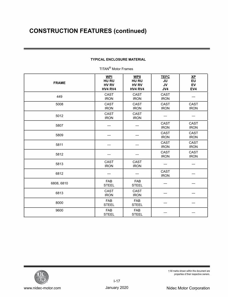
TYPICAL ENCLOSURE MATERIAL
TITAN® Motor Frames
FRAME
WPIHU RUHV RV
HV4 RV4
WPIIHU RUHV RV
HV4 RV4
TEFCJUJV
JV4
XPEUEV
EV4
449 CASTIRON
CASTIRON
CASTIRON ---
5008 CASTIRON
CASTIRON
CASTIRON
CASTIRON
5012 CASTIRON
CASTIRON --- ---
5807 --- --- CASTIRON
CASTIRON
5809 --- --- CASTIRON
CASTIRON
5811 --- --- CASTIRON
CASTIRON
5812 --- --- CASTIRON
CASTIRON
5813 CASTIRON
CASTIRON --- ---
6812 --- --- CASTIRON ---
6808, 6810 FAB STEEL
FAB STEEL --- ---
6813 CASTIRON
CASTIRON --- ---
8000 FAB STEEL
FAB STEEL --- ---
9600 FAB STEEL
FAB STEEL --- ---
CONSTRUCTION FEATURES (continued)
January 2020www.nidec-motor.com Nidec Motor Corporation
I-18
† All marks shown within this document are properties of their respective owners.
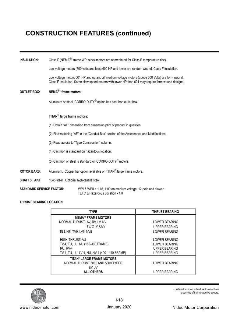
INSULATION: Class F (NEMA®† frame WPI stock motors are nameplated for Class B temperature rise).
Low voltage motors (600 volts and less) 600 HP and lower are random wound, Class F insulation.
Low voltage motors 601 HP and up and all medium voltage motors (above 600 Volts) are form wound, Class F insulation. Some slow speed motors with lower HP than 601 may require form wound designs.
OUTLET BOX: NEMA®† frame motors:
Aluminum or steel. CORRO-DUTY® option has cast-iron outlet box.
TITAN® large frame motors:
(1) Obtain “AF” dimension from dimension print of product in question.
(2) Find matching “AF” in the “Conduit Box” section of the Accessories and Modifications.
(3) Read across to “Type Construction” column.
(4) Cast iron is standard on hazardous location.
(5) Cast iron or steel is standard on CORRO-DUTY® motors.
ROTOR BARS: Aluminum. Copper bar option available on TITAN® large frame motors.
SHAFTS: AISI 1045 steel. Optional high-tensile steel.
STANDARD SERVICE FACTOR: WPI & WPII = 1.15, 1.00 on medium voltage, 12-pole and slower TEFC & Hazardous Location - 1.0
THRUST BEARING LOCATION:
TYPE THRUST BEARINGNEMA®† FRAME MOTORS
NORMAL THRUST: AV, RV, LV, NV TV, CTV, CEV IN-LINE: TV9, LV9, NV9
HIGH-THRUST: AU TV-4, TU, LU, NU (180-360 FRAME) RU, RV-4 TV-4, TU, LU, LV-4, NU, NV-4 (400 - 440 FRAME)
LOWER BEARINGUPPER BEARINGLOWER BEARING
LOWER BEARINGLOWER BEARINGUPPER BEARINGUPPER BEARING
TITAN® LARGE FRAME MOTORSNORMAL THRUST 5000 AND 5800 TYPES
EV, JV ALL OTHERS
LOWER BEARING
UPPER BEARING
CONSTRUCTION FEATURES (continued)
January 2020www.nidec-motor.com Nidec Motor Corporation
I-19
† All marks shown within this document are properties of their respective owners.
This pricing guide is intended to provide the user with Nidec Motor Corporation product capabilities for vertical motors. Because of the special nature of this product, the following outlines the basic requirements for processing an order.
A) HP, speed
B) Enclosure type (if hazardous location - details class, group and temperature code)
C) Altitude and ambient
D) Service factor
E) Insulation class
temperature rise @ 1.0 or 1.15
F) Pump thrust
@ Design – Rating life requirement
@ Shut off
@ Up-thrust conditions, continuous or momentary
G) Base diameter
H) If HOLLOSHAFT® – head shaft diameter
I) Inverter duty – type of inverter and speed range
J) Voltage and frequency
K) If Solid Shaft – details of shaft requirements
L) Special accessories – i.e. space heaters or RTDs
For further details or questions regarding our capabilities, please contact your distributor or nearest Nidec Motor Corporation regional office.
PRICE GUIDE