General Information and Specifications - Direct · PDF fileTable of Contents ii List of...
31
MODEL: PRO-6LR 6,OOO LB. LOW-RISE AUTOMOBILE LIFT IN50008 Rev. B 07/24/2007
Transcript of General Information and Specifications - Direct · PDF fileTable of Contents ii List of...

MODEL: PRO-6LR
6,OOO LB. LOW-RISE AUTOMOBILE LIFT
IN50008 Rev. B 07/24/2007

Table of Contents
i
Table of Contents Chapter/Paragraph Page Registration......................................................................................................................................... iii Warranty ............................................................................................................................................. iv Safety Summary .................................................................................................................................. v
General Safety Instructions .............................................................................................................. v Warnings, Cautions, and Notes........................................................................................................ v Hazardous Material Description, Precautions and First Aid ............................................................. v Toxicological Properties .................................................................................................................. vi Precautionary Measures: ................................................................................................................ vi Protective Equipment (Type)........................................................................................................... vi First Aid Measures ......................................................................................................................... vii
1 General Information and Specifications.....................................................................................1-1 1.1 General Information............................................................................................................1-1 1.2 Specifications .....................................................................................................................1-1
2 Installation and Preparation for Use ..........................................................................................2-1 2.1 General Information............................................................................................................2-1 2.2 Tools and Equipment Required ..........................................................................................2-1 2.3 Foundation Requirements ..................................................................................................2-1 2.4 Installation ..........................................................................................................................2-1 2.5 Installation test....................................................................................................................2-2
3 Operating Instructions................................................................................................................3-1 3.1 Safety Procedures ..............................................................................................................3-1 3.2 Daily Pre-Operation Check (8-Hours).................................................................................3-1 3.3 Controls ..............................................................................................................................3-2 3.4 Operation............................................................................................................................3-2
3.4.1 Loading Vehicle...........................................................................................................3-2 3.4.2 Raising Vehicle............................................................................................................3-2 3.4.3 Lowering Lift ................................................................................................................3-3
4 Maintenance and Troubleshooting ............................................................................................4-1 4.1 Maintenance .......................................................................................................................4-1
4.1.1 Owner/Employer Responsibilities................................................................................4-1 4.1.2 Periodic Maintenance Schedule..................................................................................4-1
4.1.2.1 Daily Pre-Operation Check (8-Hours) ..................................................................4-1 4.1.2.2 Monthly Maintenance (every month) ....................................................................4-1 4.1.2.3 Special Maintenance Tasks .................................................................................4-2
4.2 Troubleshooting..................................................................................................................4-2 4.2.1 Motor Does Not Operate .............................................................................................4-2 4.2.2 Motor Functions but Lift Will Not Rise .........................................................................4-2 4.2.3 Oil Blows out Breather of Power Unit ..........................................................................4-3 4.2.4 Motor Hums and Will Not Run.....................................................................................4-3 4.2.5 Lift Jerks Going Up and Down.....................................................................................4-4 4.2.6 Oil Leaks .....................................................................................................................4-4 4.2.7 Lift Makes Excessive Noise.........................................................................................4-4
5 Illustrated Parts Breakdown.......................................................................................................5-1 5.1 Illustrated Parts Breakdown Information.............................................................................5-1 5.2 Complete Parts Listing .......................................................................................................5-7
5.2.1 Hardware Bag #1 ........................................................................................................5-7 5.2.2 Master (Complete) Parts Listing..................................................................................5-7

Table of Contents
ii
List of Figures Figure Page Figure 1-1. PRO-6LR Lift ..................................................................................................................1-1 Figure 2-1. Installation ......................................................................................................................2-2 Figure 3-1. PRO-6LR Controls..........................................................................................................3-3 Figure 5-1 Illustrated Parts Breakdown – Sheet 1 of 3 .....................................................................5-2 Figure 5-1 Illustrated Parts Breakdown – Sheet 2 of 3 .....................................................................5-4 Figure 5-1 Illustrated Parts Breakdown – Sheet 3 of 3 .....................................................................5-6
List of Tables Table Page Table 1-1 Basic Specifications..........................................................................................................1-1 Table 3-1. PRO-V10 Controls ...........................................................................................................3-2 Table 5-1 Parts Listing – Page 1 of 3................................................................................................5-3 Table 5-1 Parts Listing – Page 2 of 3................................................................................................5-5 Table 5-1 Parts Listing – Page 3 of 3................................................................................................5-7 Table 5-2. Hardware Bag #1.............................................................................................................5-7 Table 5-3 Master (Complete Parts listing..........................................................................................5-7 Table 5-3 Master (Complete Parts listing (Cont.)..............................................................................5-8

Registration
iii
Registration READ THIS ENTIRE MANUAL BEFORE OPERATION BEGINS. RECORD BELOW THE FOLLOWING INFORMATION WHICH IS LOCATED ON THE SERIAL NUMBER DATA PLATE Serial No.
Model No.
Date of Installation
RECORD BELOW THE FOLLOWING CUSTOMER INFORMATION Company Name
*Contact Person
Street Address
City
State
Phone
Fax
* Optional Fields NOTE: To validate warranty, this information must be copied and either faxed or mailed to: Hanmecson International, Inc. 2447 Riverbend Drive West Fort Worth, TX 76118 Fax: 817-284-2870

Warranty
iv
Warranty The structural components on your new automotive lift are warranted for five years on equipment. Operating components are warranted one year to the original purchaser, to be free of defects in material and workmanship. The manufacturer shall repair or replace at their option for this period those parts returned to the factory freight prepaid, which prove after inspection to be defective. This warranty only applies to the original purchaser of the equipment. This warranty does not extend to defects caused by ordinary wear, abuse, misuse, shipping damage, or damage as the result of improper maintenance. This warranty is exclusive and in lieu of all other warranties expressed or implied. In no event shall the manufacturer be liable for special, consequential or incidental damages for the breach or delay in performance of the warranty. The manufacturer reserves the right to make design changes or add improvements to its product line without incurring any obligation to make such changes on product sold previously. This warranty shall be governed under the laws of the state of Texas, and shall be subject to the exclusive jurisdiction of the Court in the state of Texas in the county of Tarrant.

Safety Summary
v
Safety Summary General Safety Instructions This summary describes physical and chemical processes that may cause injury or death to personnel, or damage to equipment if not properly followed. This safety summary includes general safety precautions and instructions that must be understood and applied during operation and maintenance to ensure personnel safety and protection of equipment. Prior to performing any task, the WARNINGs, CAUTIONs, and NOTEs included in that task should be reviewed and understood. Warnings, Cautions, and Notes WARNINGs and CAUTIONs are used in this manual to highlight operating or maintenance procedures, practices, conditions or statements that are considered essential to protection of personnel (WARNING) or equipment (CAUTION). WARNINGs or CAUTIONs immediately precede the step or procedure to which they apply. NOTEs are used in this manual to highlight operating or maintenance procedures, practices, conditions or statements that are not essential to the safeguarding of personnel or equipment. NOTEs may precede or follow the step or procedure, depending on the information to be highlighted. The Headings used and their definitions are as follows.
WARNING
Highlights essential operating or maintenance procedure, practice, condition, statement, etc. that if not strictly observed, could result in injury to, or death of, personnel or long term health hazards.
CAUTION
Highlights essential operating or maintenance procedure, practice, condition, statement, etc. that if not strictly observed, could result in damage to, or destruction of equipment.
NOTE
Highlights essential operating or maintenance procedure, practice, condition, or statement.
Hazardous Material Description, Precautions and First Aid This lift uses ISO Grade 32 AW, 46 or other good grade non-detergent hydraulic oil. Its toxicological properties, precautionary measures to take, and first aid measures are stated below.

Safety Summary
vi
Toxicological Properties Primary Route of Exposure: Eyes Skin Inhalation Effects of Overexposure Acute: Eyes: May cause minimal irritation, experienced as temporary discomfort. Skin: Brief contact is not irritating. Prolonged contact, as with clothing wetted with material, may cause defatting of skin or irritation, seen as local redness with possible mild discomfort. Other than the potential skin irritation effects noted above, acute (short term) adverse effects are not expected from brief skin contact; see other effects, below, for information regarding potential long term effects. Inhalation: Vapors or mist, in excess of permissible concentrations, or in unusually high concentrations generated from spraying, heating the material or as from exposure in poorly ventilated areas or confined spaces, may cause irritation of the nose and throat, headache, nausea, and drowsiness. Ingestion: If more than several mouthfuls are swallowed, abdominal discomfort, nausea, and diarrhea may occur. Chronic: No adverse effects have been documented in humans because of chronic exposure. Sensitization Properties: Unknown. Medical Conditions Aggravated by Over Exposure: Because of its defatting properties, prolonged and repeated skin contact may aggravate an existing dermatitis (skin condition). Exposure Control for Total Product: None established for product. For Mineral oil mist: OSHA PEL-TWA 5 mg/m3, ACGIH TLV-TWA 5 mg/m3. Other Remarks: Material from high pressure equipment, pinhole leaks, or high pressure line failure can penetrate the skin and, if not properly treated, can cause severe injury, including disfigurement, loss of function, or even require amputation of the affected area. To prevent such serious injury, immediate medical attention should be sought even if the injection injury appears to be minor. Precautionary Measures: Avoid prolonged breathing of vapor, mist, or gas. Workers should wash exposed skin several times daily with soap and water. Protective Equipment (Type) Eye/Face Protection: Safety glasses, chemical type goggles, or face shield recommended to prevent eye contact.

Safety Summary
vii
Skin Protection: Workers should wash exposed skin several times daily with soap and water. Soiled work clothing should be laundered or dry-cleaned. Respiratory Protection: Airborne concentrations should be kept to lowest levels possible. If vapor, mist or dust is generated and the occupational exposure limit of the product, or any component of the product, is exceeded, use appropriate NIOSH or MSHA approved air purifying or air-supplied respirator after determining the airborne concentration of the contaminant. Air supplied respirators should always be worn when airborne concentration of the contaminant or oxygen content is unknown. Ventilation: Adequate to meet occupational exposure limits (see below). Mineral oil mist: OSHA PEL-TWA 5 mg/m3, ACGIH TLV-TWA 5 mg/m3. Procedures in Case of Accidental Release, Breakage or Leakage: Ventilate area. Avoid breathing vapor. Wear appropriate personal protective equipment, including appropriate respiratory protection. Contain spill if possible. Wipe up or absorb on suitable material and shovel up. Prevent entry into sewers and waterways. Avoid contact with skin, eyes or clothing. Waste Disposal Methods: Dispose of this product in accordance with local and/or national regulations. Precautions to be taken in: Handling: Minimum feasible handling temperatures should be maintained. Storage: Periods of exposure to high temperatures should be minimized. Water contamination should be avoided.
First Aid Measures
Eyes: Flush eyes with plenty of water for several minutes. Get medical attention if eye irritation persists. Skin: Wash skin with plenty of soap and water for several minutes. Get medical attention if skin irritation develops or persists. Ingestion: If more than several mouthfuls of this material are swallowed, give two glasses of water (16 oz.). Get medical attention. Inhalation: If irritation, headache, nausea, or drowsiness occurs, remove to fresh air. Get medical attention if breathing becomes difficult or respiratory irritation persists. Other Instructions: Remove and dry-clean or launder clothing soaked or soiled with this material before reuse. Dry cleaning of contaminated clothing may be more effective than normal laundering. Inform individuals responsible for cleaning of potential hazards associated with handling contaminated clothing.

Safety Summary
viii
Note to Physician: High-pressure injection of material can cause severe injury. Failure to debride the wound of all residual material can result in disfigurement, loss of function, or may require amputation of the affected area
General Information and Specifications
1-1
1 General Information and Specifications 1.1 General Information The PRO-6LR is a portable low-rise lift capable of lifting 6,000 lbs. that offers the following features:
• Only 3-7/8 in. lowered height allows you to service low ground clearance vehicle. • Safer operation by use of an automatic/Safety latch engage/disengage feature • Portable design that allows rapid relocation of lift by one person • Variable lifting height by means of five locking points available up to 26 in. in height
Figure 1-1 offers a view of the lift.
Figure 1-1. PRO-6LR Lift 1.2 Specifications The basic specifications are shown in table 1-1 as follows:
Table 1-1 Basic Specifications
Specification Value Lifting capacity 6,000 lb. Lifting height 26 in. Lowered height 3-7/8 in. Lifting time 36 sec. Motor 110vac, 1 hp
The remaining chapters in this manual are as follows: Chapter/Title: Page: 2 - Installation and Preparation for Use 2-1 3 - Operating Instructions 3-1 4 - Maintenance and Troubleshooting 4-1 5 - illustrated Parts Breakdown 5-1

General Information and Specifications
1-2
This page intentionally left blank.

Installation and Preparation for Use
2-1
2 Installation and Preparation for Use 2.1 General Information Any freight damage must be noted on the freight bill before signing and reported to the freight carrier with a freight claim established. Identify the components and check for shortages. If shortages are discovered, contact Hanmecson International, Inc. immediately. 2.2 Tools and Equipment Required Common mechanic’s tools are all that is required to install the lift. 2.3 Foundation Requirements Consult building owner and / or architect’s plans when applicable to establish the best lift location. The lift should be located on a relatively level floor with 4 in. minimum thickness, 3000-psi concrete slab that has been properly cured. 2.4 Installation
WARNING
Failure to heed this warning can result in serious injury or even death as well as damage to the equipment. This lift should be installed by qualified lift installers only who are familiar with this particular lift model and its requirements. The frame on this lift must not be twisted, bent or misaligned by un-level floors. Misalignment may cause damage to the lift. Install as given in the following steps. 1. Select the site where the lift is to be used meeting the following requirements:
a) Foundation meets the requirements given in paragraph 2.3
CAUTION
Failure to heed this caution can result in damage to the lift or other equipment/vehicles. In the following step, remember that the lift will move rearward approximately 14" when raised. Allow enough room to the rear.
b) Make sure there are no obstructions and adequate clearance around the lift location.
c) Select a site for the power unit so that operators have a full, unobstructed view of the lift.
2. Place the lift in its intended use position making sure the hydraulic cylinder is placed towards
the front of the bay. (Engine should be positioned at cylinder side of lift). 3. Refer to figure 2-1on page 2-2 and do the following:
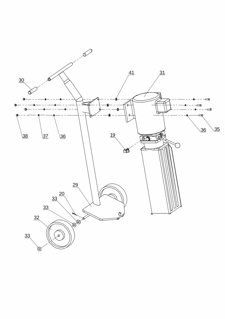
a) Install the power unit (item 31) to the dolly using the following hardware as shown:

Installation and Preparation for Use
2-2
ITEM DRAWING # DESCRIPTION QTY 35 GB70-85- M8x25 M8x25 HEX BOLT 4 36 GB97.1-85-8 ϕ8 FLAT WASHER 8 37 GB93-87-8 ϕ8 LOCK WASHER 4 38 GB41-86-M8 M8 NUT 4
b) Install the 90-degree hydraulic fitting (item 19) in the pressure port of the power unit (item
31). The pressure port is covered with a plastic plug that must be removed.
c) Install the straight hydraulic fitting (item 39) at the pressure port of the cylinder. The pressure port is covered with a plastic plug that must be removed.
d) Install the pipe extension (item 40) to the hydraulic fitting (item 39).
e) After the fittings are installed, connect the 120' hydraulic hose (item 34) between hydraulic
fitting (item 19) on the power unit and the pipe extension (item 40) on the lift cylinder (item 8). Make sure that they are not over-tightened.
f) Remove filler cap on power unit and fill with 1-1/2 gallons of 10 wt. hydraulic oil or 6 quarts
of Dextron III automatic transmission fluid
g) Replace the filler cap.
h) Plug the power unit into a 110 vac, 3-wire receptacle.
Figure 2-1. Installation
2.5 Installation test Test the Lift operation by doing the following: 1. Using the lowering handle on the pump unit, raise lift only HALF WAY then lower completely.
Repeat at least 12 times.

Installation and Preparation for Use
2-3
NOTE
During the initial testing, the lift will descend slowly. This is normal. It helps to add a payload, no greater than 500 pounds to help speed up the decent during this process.
2. Check all hoses for leaks. Tighten if necessary.

Installation and Preparation for Use
2-4
This page intentionally left blank.
Operating Instructions
3-1
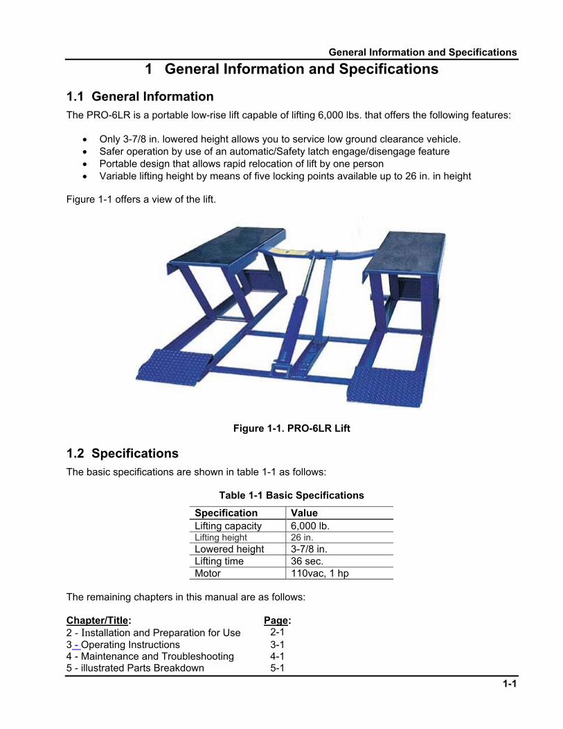
3 Operating Instructions 3.1 Safety Procedures
WARNING
Failure to adhere to the following can result in death or injury, or damage to the equipment and vehicle. All personnel will be made aware of this warning and trained in the use and care of the lift.
1. Read and understand all safety warning procedures before operating lift. 2. Keep hands and feet clear. Remove hands and feet from any moving parts. Keep feet clear of
lift when lowering. Avoid pinch points. 3. Keep work area clean. Cluttered work areas invite injuries. 4. Consider work area environment. Do not expose equipment to rain. Do not use in damp or wet
locations. Keep area well lighted. 5. Only trained operators should operate this lift. All non-trained personnel should be kept away
from work area. Never let untrained personnel operate lift. 6. Use lift correctly. Use lift in the proper manner. Never use lifting adapters other than what is
approved by the manufacturer. 7. Do not override self-closing lift controls. 3.2 Daily Pre-Operation Check (8-Hours)
NOTE
Occupational Safety and Health Administration (OSHA) and the American National Standards Institute (ANSI) require users to inspect lifting equipment at the start of every shift. These and other periodic inspections are the responsibility of the user.
WARNING
Failure to perform the daily pre-operational check can result in expensive property damage, lost production time, serious personal injury, and even death. The safety latch system must be checked and working properly before the lift is put to use.
The daily pre-operational check consists of the following: 1. Before raising a vehicle, check for leaks, and possible binding of lift components. Make sure
that the hydraulic hose is clear of any possible pinch points.

Operating Instructions
3-2
2. Make sure lift is in fully lowered position before vehicle is brought on lift. 3. If the lift is not operating properly, DO NOT use until repairs or adjustments are made. 3.3 Controls The controls are located on the power unit on the lift dolly They are shown in figure 3-1 in page 3-3 and their use and function given in table 3-1 below.
Table 3-1. PRO-V10 Controls
Item No. Type Purpose 1 Push button switch Controls electrical power to the power unit. Push to turn-on,
and push again to turn-off the power unit. Lights when ON. 2 Lowering Handle Used to relieve hydraulic pressure when pressed down. 3 Reservoir cap Cap for the power unit fluid reservoir. Remove to add fluid.
3.4 Operation Operate the lift as given in the following paragraphs. 3.4.1 Loading Vehicle Load the vehicle as follows: 1. Clear area of personnel and make sure lift is fully lowered position. 2. Drive vehicle over the lift making sure that the center-line of the vehicle is positioned properly
over the lift pads 3.4.2 Raising Vehicle To raise the vehicle perform the following steps:
WARNING
Failure to pay attention to this warning can result in death or serious injury, or damage to the lift and vehicle. The lift was designed to raise only passenger cars and light duty trucks. Many full size trucks, specialty or modified vehicles cannot be raised with this type lift. Never use lifting adapters other than those specifically designed for this lift.
1. Position the pads underneath the vehicle making sure that they make secure contact with the
frame or other recommended lifting point. 2. Before raising the lift, make sure the weight of the vehicle does not exceed the rated capacity
of the lift. DO NOT park wheels directly on lift pads 3. Depress the push button switch to the ON position to commence lifting. 4. Raise lift until the vehicles tires clear the floor.

Operating Instructions
3-3
Figure 3-1. PRO-6LR Controls
5. Stop and check to make sure the vehicle is secure and the lifting pads are still in contact with
the frame.
WARNING
Failure to pay attention to this warning can result in death or serious injury, or damage to the lift and vehicle. ALWAYS make sure that the safeties are engaged before any attempt is made to work on or near
the vehicle. 6. Continue to raise vehicle until the safety lock bars drop into position. Press the Push button
switch to turn the power unit OFF.
3.4.3 Lowering Lift Lower the lift as follows: 1. Clear area of personnel and tools above and below before lowering lift. 2. Raise the lift until the release cam has dropped into the UNLOCKED position on both safety
lock bars.

Operating Instructions
3-4
3. Push the lowering handle until the lift starts to descend. Stay clear of lift area. 4. Fully lower the lift and remove all lifting adapters before driving vehicle away.

Maintenance and Troubleshooting
4-1
4 Maintenance and Troubleshooting 4.1 Maintenance 4.1.1 Owner/Employer Responsibilities The owner/employer is responsible for, and will do the following: 1. Shall establish procedures to periodically maintain, inspect and care for the lift in accordance
with the manufactures recommended procedures to ensure its’ continued safe operations. 2. Shall provide necessary lockout / tag outs of energy sources per ANSI Z244.1 – 1982 before
beginning any lift repairs. 3. Shall not modify the lift in any manner without prior written consent of the manufacturer. 4. Shall display the operating instructions, “Lifting It Right” and “Safety Tips” supplied with the lift
in a conspicuous location in the lift area convenient to the operator. 5. Shall make sure that lift operators are instructed in the proper and safe use and operation of
the lift using the manufacturer’s instructions and “Lift It Right” and “Safety Tips” supplied with the lift.
4.1.2 Periodic Maintenance Schedule The periodic maintenance given in the following paragraphs is the suggested minimum requirements and minimum intervals; accumulated hours or monthly period, which ever comes sooner.
WARNING
Failure to heed this warning can result in death or serious injury, or damage to equipment. If you hear a noise not associated with normal lift operation, or, if there is any indication of impending lift failure - CEASE OPERATION IMMEDIATELY! - Inspect, correct and/or replace parts as required.
Periodic maintenance is to be performed on a daily, weekly, and yearly basis as given in the following paragraphs. 4.1.2.1 Daily Pre-Operation Check (8-Hours) This daily pre-operational check is shown in the Operation Chapter as it is performed on a daily basis before use of the lift. Refer to page 3-1. 4.1.2.2 Monthly Maintenance (every month) On a monthly basis, perform the following checks: 6. Inspect all hydraulic components for leaks, deformation, wear or corrosion. 7. Tighten all fasteners, screws and hydraulic fittings as required. 8. Check all wire connections. Make sure wires are connected properly. 9. Check hydraulic fluid. If it is dirty, replace with clean fluid. Always use a clean funnel and filter.

Maintenance and Troubleshooting
4-2
10. Inspect for cracks in the lock mechanism, and on other parts of the lift. Replace parts as needed.
11. Check for rust on parts. Remove rust, lubricate and paint as needed. 4.1.2.3 Special Maintenance Tasks The following items should only be performed by a trained maintenance expert. 1. Replacement of hydraulic hoses. 2. Replacement or rebuilding air and hydraulic cylinders as required. 3. Replacement or rebuilding pumps / motors as required. 4. Checking of hydraulic cylinder rod and rod end (threads) for deformation or damage.
NOTE
Relocating or changing components may cause problems. Each component in the system must be compatible; an undersized or restricted line will cause a drop in pressure. All valve, pump, and hose connections should be sealed and/or capped until just prior to use. Air hoses can be used to clean fittings and other components. However, the air supply must be filtered and dry to prevent contamination. Most important - cleanliness - contamination is the most frequent cause of malfunction or failure of hydraulic equipment.
4.2 Troubleshooting Edit as necessary. The common problems that may be encountered and their probable causes are covered in the following paragraphs: Paragraph: Problem: Page:
4.2.1 Motor Does Not Operate 4-2 4.2.2 Motor Functions But Lift Will Not Rise 4-2 4.2.3 Oil Blows Out Breather Of Power Unit 4-3 4.2.4 Motor Hums and Will Not Run 4-3 4.2.5 Lift Jerks Going Up and Down 4-4 4.2.6 Oil Leaks 4-4 4.2.7 Lift Makes Excessive Noise 4-4
4.2.1 Motor Does Not Operate Failure of the motor to operate is normally caused by one of the following: 1. Breaker or fuse blown. 2. Motor thermal overload tripped. Wait for overload to cool. 3. Faulty wiring connections; call electrician. 4. Defective up button call electrician for checking. 4.2.2 Motor Functions but Lift Will Not Rise If the motor is functioning, but the lift will not rise do the following in the order given:

Maintenance and Troubleshooting
4-3
1. A piece of trash is under check valve. Push power unit lowering handle down and push the up button at the same time. Hold for 10-15 seconds. This should flush the system.
2. Check the clearance at the plunger valve of the lowering handle. There should be 1/16 in. 3. Remove the check valve cover and clean ball and seat.
WARNING
Failure to properly relieve pressure in the following step can cause injury to personnel. This lift uses ISO Grade 32 AW, 46 or other good grade non-detergent hydraulic oil at a high hydraulic pressure. Be familiar with its toxicological properties, precautionary measures to take, and first aid measures as stated in the Safety Summary before performing any maintenance with the hydraulic system.
4. Oil level too low. Oil level should be just under the vent cap port when the lift is down. Relieve
all hydraulic pressure and add oil as required. 4.2.3 Oil Blows out Breather of Power Unit If oil blows out of the breather of the power unit, take the following actions:
WARNING
Failure to properly relieve pressure in the following step can cause injury to personnel. Failure to properly relieve pressure in the following step can cause injury to personnel. This lift uses ISO Grade 32 AW, 46 or other good grade non-detergent hydraulic oil at a high hydraulic pressure. Be familiar with its toxicological properties, precautionary measures to take, and first aid measures as stated in the Safety Summary before performing any maintenance with the hydraulic system.
1. Oil reservoir overfilled. Relieve all pressure and siphon out hydraulic fluid until at a proper level 2. Lift lowered too quickly while under a heavy load. Lower the lift slowly under heavy loads. 4.2.4 Motor Hums and Will Not Run If the motor hums but fails to run, take the following actions: 1. Impeller fan cover is dented. Remove cover and straighten. 2. Lift overloaded. Remove excessive weight from lift
WARNING
The voltages used in the lift can cause death or injury to personnel. In the following steps, make sure that a qualified electrician is used to perform maintenance
3. Faulty wiring..….... Call electrician

Maintenance and Troubleshooting
4-4
4. Bad capacitor..….. Call electrician 5. Low voltage........... Call electrician 4.2.5 Lift Jerks Going Up and Down If the lift jerks while going up and down, it is usually a sign of air in the hydraulic system. Raise lift all the way to top and return to floor. Repeat 4-6 times. Do not let this overheat power unit. 4.2.6 Oil Leaks Oil leak causes at the power unit and cylinders are normally caused by the following. Take the actions shown to fix the problem:
WARNING
Failure to heed this warning could cause serious injury or damage to the lift. Failure to properly relieve pressure in the following step can cause injury to personnel. This lift uses ISO Grade 32 AW, 46 or other good grade non-detergent hydraulic oil at a high hydraulic pressure. Be familiar with its toxicological properties, precautionary measures to take, and first aid measures as stated in the Safety Summary before performing any maintenance with the hydraulic system. Make sure that pressure is fully relieved before checking oil levels, loosening any hydraulic lines, or removing any cylinders.
1. Power unit: if the power unit leaks hydraulic oil around the tank-mounting flange check the oil
level in the tank. The level should be two inches below the flange of the tank. A screwdriver can be used as a “dipstick”.
2. Rod end of the cylinder: the rod seal of the cylinder is out. Rebuild or replace the cylinder. 3. Breather end of the cylinder: the piston seal of the cylinder is out. Rebuild or replace the
cylinder. 4.2.7 Lift Makes Excessive Noise Excessive noise from the lift is normally caused by the following. Take the corrective actions shown. 1. Leg of the lift is dry and requires grease. 2. Cylinder pulley assembly or cable pulley assembly is not moving freely. 3. May have excessive wear on pins or cylinder yoke.
Illustrated Parts Breakdown
5-1
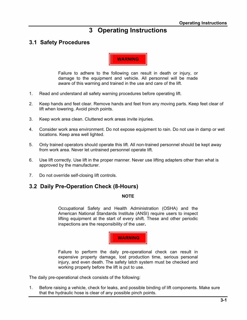
5 Illustrated Parts Breakdown Use the complete parts listing in paragraph 5-2 to perform inventory before assembly of the lift. 5.1 Illustrated Parts Breakdown Information This paragraph consists of the detailed illustrations and parts listings for the Model PRO-V10 10,000 Pound Two-Column Automotive Lift. Certain parts may be shown on more than one figure in order to illustrate their relationship with other components shown in the figure. The illustrations are shown on the left-hand pages with their corresponding parts listing shown on the right-hand pages.
NOTE
The part quantities shown are the totals for that part contained within the entire lift. Therefore, the quantities shown may be greater than what is shown on an individual sheet of the IPB illustrations

1
NOTE: Some vehicles may have the manufacturer's Service Garage Lift Point locations identified by triangle shape marks on it's undercarriage (reference ANSI/SAE J2184-1992). Also, there may be a label located on the right front door lock face showing specific vehicle lift points. If the specific vehicle lift points are not identified, refer to the "Typical Lift Points" illustrated herein. ALWAYS follow the operating instructions supplied with the lift.
Typical Lifting Points
FRO
NT
FRO
NT
FRO
NT
FRO
NT
LIFTPOINTS
LIFTPOINTS
LIFTPOINTS
LIFTPOINTS
Pickup Truck Unitized Body
Stub FramePerimeter Frame
The Owner/Employer:
• Shall ensure that lift operators are qualified and that they are trained in the safe use and operation of the lift using the manufacturer’s operating instructions; ALI/SM 93-1, ALI Lifting it Right safety manual; ALI/ST-90 ALI Safety Tips card; ANSI/ALI ALOIM-2000, American National Standard for Automotive Lifts-Safety Requirements for Operation, Inspection and Maintenance; ALI/WL Series, ALI Uniform Warning Label Decals/Placards; and in the case of frame engaging lifts, ALI/LP-GUIDE, Vehicle Lifting Points/Quick Reference Guide for Frame Engaging Lifts.
• Shall establish procedures to periodically inspect the lift in accordance with the lift manufacturer’s instructions or ANSI/ALI ALOIM-2000, American National Standard for Automotive Lifts-Safety Requirements for Operation, Inspection and Maintenance; and The Employer Shall ensure that lift inspectors are qualified and that they are adequately trained in the inspection of the lift.
• Shall establish procedures to periodically maintain the lift in accordance with the lift manufacturer’s instructions or ANSI/ALI ALOIM-2000, American National Standard for Automotive Lifts-Safety Requirements for Operation, Inspection and Maintenance; and The Employer Shall ensure that lift maintenance personnel are qualified and that they are adequately trained in the maintenance of the lift.
• Shall maintain the periodic inspection and maintenance records recommended by the manufacturer or ANSI/ALI ALOIM-2000, American National Standard for Automotive Lifts-Safety Requirements for Operation, Inspection and Maintenance.
• Shall display the lift manufacturer’s operating instructions; ALI/SM 93-1, ALI Lifting it Right safety manual; ALI/ST-90 ALI Safety Tips card; ANSI/ALI ALOIM-2000, American National Standard for Automotive Lifts-Safety Requirements for Operation, Inspection and Maintenance; and in the case of frame engaging lifts, ALI/LP-GUIDE, Vehicle Lifting Points/Quick Reference Guide for Frame Engaging Lifts; in a conspicuous location in the lift area convenient to the operator.
• Shall provide necessary lockout/tagout means for energy sources per ANSI Z244.1-1982 (R1993), Safety Requirements for the Lockout/Tagout of Energy Sources, before beginning any lift repairs.
• Shall not modify the lift in any manner without the prior written consent of the manufacturer.
OWNER/EMPLOYER RESPONSIBILITIES

2
SAFETY WARNING LABELSFOR HINGED FRAME ENGAGING LIFTS
A. This Safety Warning placardSHALL be displayed in aconspicuous location in the lift area.
B. Use one of the mountingarrangements illustrated on back ofthis placard.
Lift Owner/User Responsibilities:
C. These Safety Warning labelssupplement other documentssupplied with the lift.
D. Be certain all lift operators read andunderstand these labels, operatinginstructions and other safety relatedinformation supplied with the lift.
WARNING
©
Position vehiclewith center of gravity midway betweenadapters.
WARNING
Remain clear of lift when raising or lowering vehicle.
©
WARNING
Keep clear of pinch points when lift is moving.
©
WARNING
Clear area if vehicle is in danger of falling.
©
WARNING
Avoid excessive rocking of vehicle while on lift.
©
Keep feet clear of lift while lowering.
©
WARNING
CAUTION
Authorized personnel only in lift area.
©
CAUTION
Use vehiclemanufacturer’slift points.
©
CAUTION
Always use safety stands when removing or installing heavy components. ©
Do not operatea damaged lift.
©
SAFETYINSTRUCTIONS
Read operatingand safety manualsbefore using lift.
©
SAFETYINSTRUCTIONS
CAUTION
Lift to be used by trained operatoronly.
©
? ??
ALI/WL300csw© 1992 by ALI, Inc.
The messages and pictographsshown are generic in nature andare meant to generally representhazards common to all automotivelifts regardless of specific style.
Funding for the development andvalidation of these labels wasprovided by the Automotive LiftInstitute, PO Box 1519 New York,NY. 10101-1519.
They are protected by copyright.Set of labels may be obtained fromALI or its member companies.
Power Unit: Secure placardnear lift controls.
Lift ControlConsole:Secureplacard in anaccessiblelocation.
Proper maintenanceand inspection is necessary for safe operation. ©
SAFETYINSTRUCTIONS
3
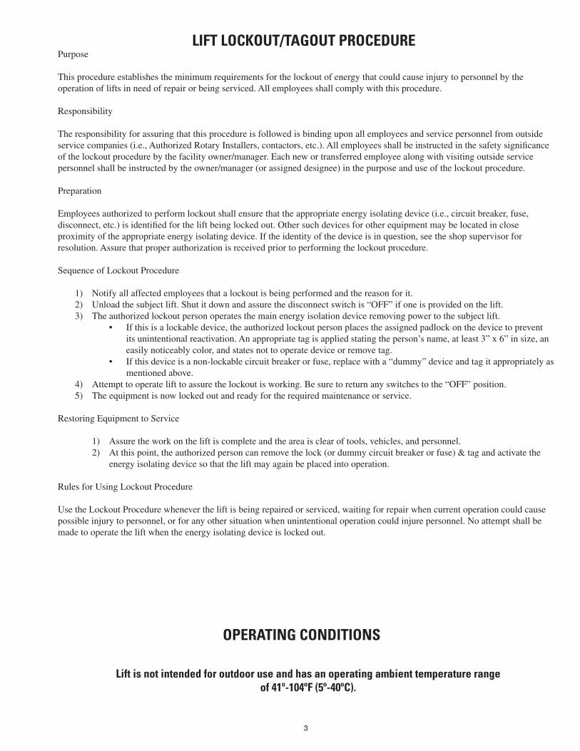
Purpose
This procedure establishes the minimum requirements for the lockout of energy that could cause injury to personnel by the operation of lifts in need of repair or being serviced. All employees shall comply with this procedure.
Responsibility
The responsibility for assuring that this procedure is followed is binding upon all employees and service personnel from outside service companies (i.e., Authorized Rotary Installers, contactors, etc.). All employees shall be instructed in the safety significance of the lockout procedure by the facility owner/manager. Each new or transferred employee along with visiting outside service personnel shall be instructed by the owner/manager (or assigned designee) in the purpose and use of the lockout procedure.
Preparation
Employees authorized to perform lockout shall ensure that the appropriate energy isolating device (i.e., circuit breaker, fuse, disconnect, etc.) is identified for the lift being locked out. Other such devices for other equipment may be located in close proximity of the appropriate energy isolating device. If the identity of the device is in question, see the shop supervisor for resolution. Assure that proper authorization is received prior to performing the lockout procedure.
Sequence of Lockout Procedure
1) Notify all affected employees that a lockout is being performed and the reason for it.2) Unload the subject lift. Shut it down and assure the disconnect switch is “OFF” if one is provided on the lift.3) The authorized lockout person operates the main energy isolation device removing power to the subject lift.
• If this is a lockable device, the authorized lockout person places the assigned padlock on the device to prevent its unintentional reactivation. An appropriate tag is applied stating the person’s name, at least 3” x 6” in size, an easily noticeably color, and states not to operate device or remove tag.
• If this device is a non-lockable circuit breaker or fuse, replace with a “dummy” device and tag it appropriately as mentioned above.
4) Attempt to operate lift to assure the lockout is working. Be sure to return any switches to the “OFF” position.5) The equipment is now locked out and ready for the required maintenance or service.
Restoring Equipment to Service
1) Assure the work on the lift is complete and the area is clear of tools, vehicles, and personnel.2) At this point, the authorized person can remove the lock (or dummy circuit breaker or fuse) & tag and activate the
energy isolating device so that the lift may again be placed into operation.
Rules for Using Lockout Procedure
Use the Lockout Procedure whenever the lift is being repaired or serviced, waiting for repair when current operation could cause possible injury to personnel, or for any other situation when unintentional operation could injure personnel. No attempt shall be made to operate the lift when the energy isolating device is locked out.
LIFT LOCKOUT/TAGOUT PROCEDURE
OPERATING CONDITIONS
Lift is not intended for outdoor use and has an operating ambient temperature range of 41º-104ºF (5º-40ºC).

11
6
14
8
12
7
20
16
13
4
24
2 10
5
115
9
3
34
28
10
39
4034
A

20 23
18
17
26
25
27
2220
21
A
36
33
3836
31
20
35
29
30
32
1937
33
33
41

Items Drawing # Description QTY 1 51053-1100 Upper Structure 1 2 51053-1200 Lower Structure 1 3 51053-1310 Front Leg Assembly 4 4 51053-1310DC Rear Leg Assembly 2 51053-2001 Rubber Pads 4
6 51053-2000 Rubber Blocks 4 7 51053-1215 Safety Bar 1 8 YG08-9100 Cylinder 1 9 51053-1401 Leg Pin, Lower Side 4 10 B22-6×12 Set Screw M6×12 16 11 B20-5×35 Set ScrewM5×35 1 12 51053-1217 Safety Latch 1 13 51053-2100 Pin, cylinder 1 14 B13-6×20 Bolts M6×20,RubberPad 16 15 B41-6 Φ6Flat Washer 16 16 B30-6 M6 Nut 16 17 51053-1501 Caster Frame 2 18 B80-3×1.25 Φ3" ×1.25" Caster 2 19 30400-9053YZ Fitting, Elbow 1 20 B52-3×30 Φ3×30 Cotter Pin 8 21 51053-1503 Caster Lock Pin 2 22 51053-1502 Caster Pin 2 23 B41-16 Φ16 Flat Washer 4 24 51053-1402 Leg Pin, Upper Side 4 25 B52-3×20 Φ3×20 Cotter Pin 2 26 51053-1506 Bolt 2 27 B41-10 Φ10 Flat Washer 2 28 B85-6 M6 Oil Zerk 8 29 51053-1800A Dolly 1 30 B81-21 Φ21.3 Handle 2 31 P/U Power Unit 1 32 B80-4×2 Φ4" ×2" Caster 2 33 B41-12C Φ12 Washer 6 34 1WB-07 Hydraulic Hose 1 35 B10-8×25 M8×25 Bolt 4 36 B41-8 Φ8 Flat Washer 8 37 B40-8 Φ8 Lock Washer 4 38 B30-8 M8 Nut 4 39 30400-9050YZ Fitting, Elbow 1 40 51053-9000 Fitting, Elbow 1 41 30400-1999 Washer 4