General Information about IEC 61850, Smart - NettedAutomation
73
Dipl.-Ing. Karlheinz Schwarz, Karlsruhe/Germany Editor of IEC 61850 and IEC 61400-25 (Wind Power Plants) Member of IEC TC 57 WG 10, WG 17 (DER), WG 18 (Hydro Power Plants) Member of IEC TC 88 PT 25 (IEC 61400-25, Wind Power Plants) Convenor of IEC TC 88 IEC 61400-25-6 (Condition Monitoring) You get comprehensive, first-hand, and neutral knowledge and experience Stack and API Integration Embedded Controller, Software Support Gateways (DNP3, Modbus, IEC 60870-104, …) Consultancy, Training NettedAutomation GmbH Im Eichbaeumle 108 76139 Karlsruhe / Germany Tel +49-721-684844 Fax +49-721-679387 [email protected] http://nettedautomation.com http://blog.iec61850.com IEC 61850 and IEC 61400-25 GLOBAL Standards for all Energy Systems Generation, Transmission, Distribution, … Smart Grids – Design, Specification, Engineering, Configuration, Automation, SCADA, Measuring, Condition Monitoring; Information Modeling, Exchange and Management 2012-11-18 GmbH GmbH Information & Communication Systems Information & Communication Systems NettedAutomation NettedAutomation GmbH GmbH GmbH GmbH Information & Communication Systems Information & Communication Systems Information & Communication Systems Information & Communication Systems NettedAutomation NettedAutomation
Transcript of General Information about IEC 61850, Smart - NettedAutomation

Dipl.-Ing. Karlheinz Schwarz, Karlsruhe/Germany Editor of IEC 61850 and IEC 61400-25 (Wind Power Plants) Member of IEC TC 57 WG 10, WG 17 (DER), WG 18 (Hydro Power Plants) Member of IEC TC 88 PT 25 (IEC 61400-25, Wind Power Plants) Convenor of IEC TC 88 IEC 61400-25-6 (Condition Monitoring) You get comprehensive, first-hand, and neutral knowledge and experience
Stack and API Integration Embedded Controller, Software Support
Gateways (DNP3, Modbus, IEC 60870-104, …) Consultancy, Training
NettedAutomation GmbH Im Eichbaeumle 108
76139 Karlsruhe / Germany Tel +49-721-684844 Fax +49-721-679387
[email protected] http://nettedautomation.com
http://blog.iec61850.com
IEC 61850 and IEC 61400-25 GLOBAL Standards for all Energy Systems
Generation, Transmission, Distribution, … Smart Grids – Design, Specification, Engineering, Configuration, Automation,
SCADA, Measuring, Condition Monitoring; Information Modeling, Exchange and Management
2012-11-18
GmbHGmbH
Information & Communication SystemsInformation & Communication Systems
NettedAutomationNettedAutomationGmbHGmbHGmbHGmbH
Information & Communication SystemsInformation & Communication SystemsInformation & Communication SystemsInformation & Communication Systems
NettedAutomationNettedAutomation

IEC 61850 & IEC 61400-25 SCC Motivation: sustainable
interoperability
The standards IEC 61850 „Communication networks and systems for power utility automation“ and IEC 61400-25 „Communications for monitoring and control of wind power plants“ provide support for sustainable interoperabil-ity: Information Models, Information Exchange Methods, Protocol Mappings, and System Configuration Language (SCL) for Power Systems (Generation, Transmission, and Distribution for HV, MV, and LV, … ).
Data Models
IEC 61850-7-4xx
Substations (7-4) 160 LN 900 DO
Hydro Power (410) 63 LN 350 DO
Decentralized Energy Res. (420) 50 LN 450 DO
IEC 61400-25-2
Wind Power 16 LN 250 DO
Logical Nodes (LN) represent real-world Inputs, Outputs, Ratings, and Settings of functions or equipment. A LN provides a list of named data objects (DO). The LN “XCBR” represents a real “circuit breaker” with the data ob-ject (DO) “Pos” (Position). IEC 61850-7-2 defines Information Exchange Methods, e.g., for the position (with Cli-ent/Server services, GOOSE, SMV). Data flow is specified by a SCL file (IEC 61850-6).
Real IED/Virtual Model
61850-6 SCL configuration file (XML)Single line diagram and functions of Substation
...
OpCnt
Pos
XCBR1
LNLNLN
61850-7-4 data (position)
61850-7-4 logical node (circuit breaker)
Models of the real world Objects; Server / Publisher
Binding real world to models
61850-7-2 services
Information Exchange Services
Map
ping
Ethernet
TCP/IP MMS
SCSM, e.g. 61850-8-1, 9-2
Communication Mappings
Communication Network
Virtualization of real world objects
MMS
HMI, … Protection
Client/Subscriber
Real world = Substation, Circuit Breaker
P GOOSESMV
GOOSESMV
XCBR1
TCTR1
Example see reverse side

Example: Measurement LN “MMXU” represents power, voltages, currents, impedances, … in a three-phase electrical system. The values can be communicated by various services. The LN “MMXU” comprises values for measurements, monitoring, configuration, set-tings, description, and substitution. These values can be communicated by various services like read (polling), reporting, GOOSE, logging and log query. Recording and logging are build upon monitored value changes. The SCL configuration file .SCD (System Configuration Description) specifies the single line diagram of the substation, the information model, the parameters of the con-trol blocks for reporting and logging, GOOSE, SV, the binding to the process and the data flow.
Virtual World
.SCD
TotWTotVArTotVATotPFHzPPVPhVAWVArVAPFZ
Total Active Power (Total P)Total Reactive Power (Total Q)Total Apparent Power (Total S)Average Power factor (Total PF)FrequencyPhase to phase voltages Phase to ground voltagesPhase currents (IL1, IL2, IL3)Phase active power (P)Phase reactive power (Q)Phase apparent power (S)Phase power factorPhase Impedance
LN „MMXU“
current / voltage samples from instrument transformers by sampled value exchange services of IEC 61850-7-2 / IEC 61850-9-2(e.g., from Merging Unit)
LN PhsBTCTRAmp
LN PhsBTVTRVol
Log
Read
Report
Configure
RetrieveModel
QueryLog
phsA.cValphsB.cValphsC.cVal
instValdead banded valueanglerange
SV SV
RCB
LN and data objects
Process bus
Station bus
GOOSE GCB
… 4.000 …samples/sec
QA1
QE1
QE2
QE3
QC1
QB1T1
...
OpCnt
Pos
XCBR
LNLNLNM
appi
ng
TCP/IPNetwork
MMS
tn+2tn+1
value (tn)
Reports/GOOSE from server/publisher to client/subscriber(or store entries into IED log)
tn+3
value (tn+3)
tn Time
stVal(StatusValue)
value (tn+1) value (tn+2)
FALSE
TRUE
MMS
LogRead, or
event-drivenReports
GOOSE/SMV Layer 2
event-driven GOOSE message
MMS
QueryLog status
change
Information flow (example)
http://nettedautomation.com/seminars , http://nettedautomation.com/iec61850li , http://blog.iec61850.com © NettedAutomation GmbH, 2008-2012; by Karlheinz Schwarz, SCC (Karlsruhe/Germany), [email protected] 2012-04-19

GmbHGmbH
Information & Communication SystemsInformation & Communication Systems
NettedAutomationNettedAutomationGmbHGmbHGmbHGmbH
Information & Communication SystemsInformation & Communication SystemsInformation & Communication SystemsInformation & Communication Systems
NettedAutomationNettedAutomation
We bring standards, smart people, intelligent devices,
tools, and systems together to build Smarter Grids!
International Standards for Power Systems Generation, Transmission, Distribution, …, Smart Grids; Design, Specification, Bidding, Engineering, Configuration, Automation,
SCADA, Condition Monitoring, Information Management …
Supplier information, capabilities, and experience profile
25+ Years of
Excellence25+ Years of
Excellence

Supplier information
Ownership Privately held by Dipl.-Ing. Karlheinz Schwarz
Registered Amtsgericht Karlsruhe HRB 8866
General Manager Ingeruth Schwarz
Major Customers
Users: AXPO, Bayernwerk, Badenwerk, Con Edison NYC, ENERGI E2, E.ON, Endessa, EdF, EdP, Energex, ETRANS, EVS, EWE, GdF, HEW, Manitoba Hydro, Hydro Quebec, Itaipu Binacional Hy-dro Power Plant Brazil, KEPCO, Mercedes Benz, PowerLink Australia, RWE, Stattkraft, TNB Malaysia, Terna, Transba, Transpower NZ, Vector, VEW, Vattenfall, …
Vendors: AEG, Beck, Beckhoff, ABB, Alstom, AREVA, Bosch, BTC, Do-ble, E+H, IDS, Eberle, GE, Hirschmann, Kloeckner & Möller, LG, OMICRON, Pepperl & Fuchs, Phoenix Contact, PSI, Repas AEG, Schweitzer Engineering Labs, Siemens, TNB, VATECH SAT, SMA, VESTAS Wind, Voith Hydro, …
Consultants: KEPRI, SKM, Teshmont, …
Company NettedAutomation GmbH
Address Im Eichbaeumle 108 76139 Karlsruhe / Germany
Telephone +49-721-684844
Fax +49-721-679387
Email [email protected]
URL http://www.nettedautomation.com
http://blog.iec61850
Foundation 2000
Vendor independent, up-to-date, neutral, and experienced!
Our knowledge and experience are asked all over – more and more!

The primary service of NettedAutomation is to provide consulting services to all enterprises for feasibility studies, information modeling, system specification, implementation and use of devices and systems; education and hands-on training for users, system integrators and vendors in all aspects of Standards used for Power Systems; support for marketing, information dissemination, procurement for distributed systems, specifying procurement requirements; and evaluation of bid-der proposals for devices, systems, tools, and open communications. The application domains cover generation, transmission, and distribution, Smart Grids, RTUs, SCADA and EMS systems, protection, automation and condition monitoring systems.
NettedAutomation has long-time experience in IEC 61850, IEC 61400-25, IEC 60870-5-10x, IEC 60870-6 TASE.2, IEC 62351, DNP3, IEC 61970 CIM, IEC 61968, IEC 61158, IEC 61499, IEEE 802.3, and ISO 9506 MMS to name just a few.
To keep abreast of the latest technical development, NettedAutomation is actively involved in work-shops, seminars, hands-on training, task forces, and committees of various professional organiza-tions such as ISO, IEC, IEEE, CEN, CENELEC, DKE, VDI, ZVEI, NIST SGIP, UCA IUG, and USE-IEC61400-25.
Curriculum vitae of Karlheinz Schwarz Dipl.-Ing. Karlheinz Schwarz (58) received his diploma degree in Information and Automation Technology at the University of Siegen (Germany) in 1982. He is married and has four children and seven grandchildren.
As a manager with Siemens Automation & Drives (communication systems) he represented the posi-tions of Siemens and the German national committee in the international standardization of MAP, MMS, MMS companion standards, Fieldbus, and other standardization projects from 1984 until 1997.
He is president of SCC (Schwarz Consulting Company), Karlsruhe (Germany) specializing in distributed automation systems. He is an independent consultant in the area of information modeling, systems and information integration, system and device engineering and configuration, open information exchange, and open communications since 1992. Mr. Schwarz has immense experience in the migration from proprietary or other solutions to standard compliant solutions.
He is involved in many standardization activities within IEC (TC 57, TC 65, and TC 88), ISO (TC 184), CENELEC (TC 65 CX), IEEE (SCC 36 "UCA", 802), and DIN since 1985. He is engaged in repre-senting main industry branches in the global standardization and providing consulting services to users and vendors. Mr. Schwarz is a well-known authority in the application of mainstream infor-mation and communication technologies. He provides guidance in the migration from proprietary so-lutions to advanced seamless and standard-based solutions applicable in substations, and power generation units, and between these and with local, regional, and central SCADA systems. Specifi-cally, his contributions to the publication of many standards are considered to be outstanding.
He has been awarded with the IEC 1906 Award in 2007 “For his strong involvement in the edition of the IEC 61850 series, its promotion inside and outside IEC, and specifical-ly its adaptation for w ind turbine plant control.”
http://www.nettedautomation.com/download/IEC1906-Award.pdf
Publications:
http://www.nettedautomation.com/marketing/scc_publications/index.html

NettedAutomation’s Capabilities and Experience Profile We assist companies in examining open communications and distributed systems technologies in sub-station automation, Smart Grids, and many other application areas outside the utility industry (for which IEC 61850 was originally designed). We support the design and implementation of IEDs com-pliant with IEC 61850 and other standards. Support for procurement requirements and evaluation of bidder proposals for IEC 61850 related devices, systems and tools can be provided. We have long term experience in implementing and organizing IEC 61850 and IEC 61850 based pilot projects.
Mr. Schwarz is the principal teacher and trainer of the seminars and training services offered and or-ganized by NettedAutomation GmbH. We have given lec-tures all over
http://www.nettedautomation.com/seminars
We offers consulting services outlined above for a wide range of information and device modeling as well as standards-based configuration, communication systems and technical applications oriented to the automation of discrete and continuous automation related to:
- International Fieldbus standard, IEC 61158 (IEC TC 65) - European Fieldbus, EN 50170 (CENELEC TC 65 CX) - National Fieldbus standards like PROFIBUS, FIP, P-Net - Actuator Sensor Interface (ASI) or IEEE 802 LAN/WAN - Utility Comm. Architecture (UCA™), IEEE SCC 36 - Communication networks and systems for power utiliy
automation, IEC 61850 (IEC TC 57) - Telecontrol equipment and system, IEC 60870-5-10x - Communications for monitoring & control of wind power
plants, IEC 61400-25 (IEC TC 88) and IEC 61400-25-6 on Information models for condition monitoring systems (IEC TC 88)
- Communications Systems for Distributed Energy Resources (DER), IEC 62350 (IEC TC 57) - Hydroelectric power plants – Communication for monitoring and control, IEC 62344 (IEC TC 57) - Intercontrol Center Communications Protocol (ICCP), IEC 60870-6 TASE.2 (IEC TC 57) - Common information models (CIM), IEC 61970 (IEC TC 57) - Accreditation, Testing and Certification of IT products (DIN Test Lab Auditor), Quality Management - Standard for the Exchange of Product Model Data (STEP) - Application and Function block modeling IEC 61499 (IEC TC 65) - Process Control Functionblocks and Device Description Language, IEC 61804 (IEC TC 65) - Open Systems Application Frameworks, ISO 15745 (ISO TC 184 SC5) - Manufacturing Automation Protocol (MAP), MiniMAP/FAIS - Manufacturing Message Specification, MMS, ISO 9506 (ISO TC 184)
Visit my Blog to get the latest: http://blog.iec61850.com
Learn firsthand what you need to know about these standards
and products!

Appendix: Personal education and qualifications of Karlheinz Schwarz
1. Education
1958 – 1962 Elementary School
1962 – 1965 Secondary School
1965 – 1967 Secondary School (Gymnasium)
1967 – 1969 Technical School
1969 – 1972 Apprenticeship as electrical mechanic and electronics (Siemens)
1973 – 1974 Service technician responsible for alarm systems (Siemens: fire alarm systems, bur-glar alarm systems, …)
1975 – 1977 Academic high school (Hessenkolleg)
1977 – 1982 Study of electrical engineering and IT at University Siegen (degree: Dipl.-Ing.)
1981 – 1997 Employee at Siemens Automation (responsible for standardization of comms)
1992 – present Consultant and trainer for communication and automation (see above and below)
2. Training experience since 2002
Mr. Schwarz has trained almost 3,000 experts all over. Most seminars have been conducted as in-house courses. Attendees from more than 700 companies have attended. Attendees from small, me-dium and big utilities and big vendors have attended. An excerpt is shown in the following table:
Year Training in Countries Courses Attendees
2002 China 2 30
2003 Denmark, Spain 2 22
2004 Spain, Germany, France, USA, China, South Africa, Malaysia 8 199
2005 South Korea, Mexico, Denmark, Canada, Switzerland, Germany, South Africa, Australia, Israel
12 299
2006 Germany, Italy, Spain, India, Canada, UK, Portugal, France, Austria, USA 18 545
2007 Russia, Germany, Portugal, USA, France, Canada, South Korea, Australia, New Zealand
11 252
2008 Germany, Slovenia, Canada, USA, France, Malaysia, South Korea, Australia, New Zealand, Sweden
20 379
2009 Mexico, Russia, Italy, Germany, Malaysia, USA, Australia 15 220
2010 Iceland, Spain, Ireland, Argentina, Brazil, Germany, Japan, Denmark, USA, Philippines, Sweden, Australia, France
20 276
2011 France, UK, Germany, Australia, South Korea, Switzerland, Zimbabwe, Cana-da, Belgium, USA, China, Austria, Brazil
33 542
2012 (Sept)
Germany, India, Belgium, Israel, Italy, Sweden, USA, South Korea, China, Taiwan
18 262
159 3.026

3. Standardization experience
Mr. Schwarz is (was) a principal contributor in the following standardization projects (either project member or as the technical lead), representing many German industries (users and vendors):
ISO ISO TC 184/SC5 Architecture, Communications, Integration Frameworks Member 1985-2012
ISO TC 184/SC5/WG 5 Open Systems Application Frameworks Member 1985-2005
ISO TC 184/SC5/WG 2 Communications and interconnection (MMS, ...) Mem-ber/Chairman
1985-2005/1998-2005
IEC IEC TC 57 Power Systems Control and Associated Communications Member 1992-2012
IEC TC 57 SPAG Strategic Policy Advisory Group Invited Guest
IEC TC 57 WG 07 Protocols compatible with ISO/OSI and ITU Member 1992-2000
IEC TC 57 WG 10 Power system IED communication and associated data models / Communication and systems within Substations (IEC 61850)
Member/editor of 61850
1995-2012
IEC TC 57 WG 17 Communications Systems for Distributed Energy Resources (DER) – based on IEC 61850
Member 2004-2012
IEC TC 57 WG 18 Hydroelectric power plants – Communication for monitoring and control – based on IEC 61850
Member 2004-2012
IEC TC 57 WG 19 Interoperability within TC 57 in the long term Member 2005-2012
IEC TC 65 WG 6 Functionblocks (IEC 61499) Member 1990-2002
IEC TC 65 PJWG Device Profiles Member 1998-2002
IEC TC 65C WG 1 Message data format for information transferred on process and control data highways, Profiles
Member 1983-2006
IEC TC 65C WG 6 Fieldbus (IEC 61158) Member 1997-2000
IEC TC 65C WG 7 Functionblocks and Data Descriptive Language (IEC 61804) Member 1996-1999
IEC TC 88 PT 25 Communications for monitoring and control of wind power plants (IEC 61400-25-1/-2/-3/-4/-5) – based on IEC 61850
Member/editor of 61400-25
2001-2012
IEC TC 88 PT 25 / IEC 61400-6
Communications for monitoring and control of wind power plants (IEC 61400-25-6) – Logical node classes and data clas-ses for condition monitoring
Convenor 2006-2011
IEEE IEEE 802.3 /.15 LAN, WAN Member 1998-2001
IEEE SCC 36 Utility Communication Architecture Member 1996-2000
CENELEC CENELEC TC 65 CX Fieldbus Communication Member 1992-2000
CEN CEN TC 310/TG ICOM Task Group on industrial communications Member 1994-1996
MMS Forum
EPRI, Electric Power Research Institute
Communications and application modelling in the area of power utilities (UCA, ICCP)
Member 1992-1998
NAM DKE/NAM/NI 96.5 Architektur und Kommunikation Member 1985-1998
DKE/NAM/NI GA 96.5.2 Kommunikation und Datenaustausch (MMS, ...) Chairman 1985-2002
DKE DKE FB 9 AK AP FB 9 Arbeitskreis Arbeitsplanung Member 1989-2003
KG-ILT Koordinierungsgruppe Industrielle Leittechnik Member 1989-2003
K 261 Mirror of IEC TC 8: System aspects of electrical energy supply Member 2003-2008
DKE K 950 Kommunikation und Informationslogistik Member 1998-2001
DKE AK 956.0.2 Kommunikationsdienste, Process Control Member 1992-1997
DKE K 956 Feldbus Member 1986-2012
DKE AK 956.3.1 Functionblocks and Data Descriptive Language Chairman 1995-206
DKE K 952 Netzleittechnik Vice Chair-man/member
1992-2012
DKE AK 952.0.7 Protocols compatible with ISO/OSI and ITU Member 1992-2005
DKE AK 952.0.10 Stationsleittechnik Member 1995-2012
DKE AK 952.0.17 Kommunikation für verteilte Energieversorgung (TC 57 WG 17) Member 2005-2012
DKE K 383.0.1 Kommunikation für Windenergieanlagen Chairman 2001-2012
GMA GMA AK 4.2 Kommunikation in verteilten Systemen Member 1996-1998
VDMA Fachverband InCom Industrial Communications Member 1990-1996
ZVEI ZVEI GA IK Gemeinschaftsausschuss Industrielle Kommunikation Member 1986-2012
2012-08-28

| MONITORMONITOR | 1/201204
F E A T U R E
Intelligent, safe electrical power distribution networks were invented at the
start of electrifi cation and have been further developed up to the present
day. Electrical fuses, protective devices and monitoring devices have been
phenomenal in the protection of life and technical installations for more
than 100 years. Without these "smart" devices a fault-free, fail-safe electrical
energy supply system would be inconceivable and the supply of electrical
energy much too dangerous.
Smart Grids

05 1/2012 | MONITORMONITOR |
RELIABLE ENERGY DELIVERY
– A 19th century invention
Since the 19th century engineers have devel-
oped, tested, used on a large-scale and con-
tinuously improved suitable solutions for
the safe and reliable operation of the rapidly
growing supply of ever more applications
with electrical energy. During the sustained further development
of the supply systems, it is necessary to handle the available
resources (energy sources, technical installations and individuals
with experience) as well as the laws of physics both responsibly
and in a "smart" manner.
Smart grids help to make it possible to use physics safely and reliably
for the benefi t of man – in the past, today and in the future

F E A T U R E
06 | MONITORMONITOR | 1/2012
ronmentally acceptable assurance of the supply of energy."
These days a differen-tiation is made between smart markets (in which the market participants who offer or require ener-gy organise themselves) and smart grids (the technical installations and processes to be fur-ther developed that are
needed for high availability, effi cient and safe supply based on the laws of physics). Even though both are closely linked, they do provide some
orientation in the maze of discussions.
Smart markets with the high volatility of renewable energy sources place comprehensive requirements on smart grids; meeting these requirements requires above all that the solutions are in harmony with the laws of physics for the electrical system. Controlling the volatility of the availability of water and sunlight in the supply of foodstuffs by means of storage, transport and distribution can be taken as an example for the smart supply of energy of the future. The volatile availability of solar and wind energy could contribute to a secure, high-availability, effi cient supply by means of increasing storage.
Smart energy supply
The system for the supply of electrical energy has been in construction for more than 130 years. Along with the high-availability provision of electrical energy, the protection of lives and technical installations has had a signifi cant impact on the development of the supply system. Special con-cepts, processes and devices were "smart" from the start – the intelligent, selective shut down of a faulty electrical circuit or an intelligently planned redundant system topol-ogy result in minimal interruption in supply in the event of a malfunction.
Such a smart energy supply system that strictly follows the laws of physics is increasing viewed by politics, commerce, science and the public in relation to the conserva-tion of natural resources and the protection of the environment, as well as in relation to the aim of generating profi ts. Smart grids are viewed as an effective instrument to achieve these goals.
The energy revolution and the increasing interest in renewable energy sources and storage options (for instance pumped storage, gas or heat storage systems) are increasingly frequently viewed in conjunction with new technological capabilities for the quick and safe exchange of information – a core topic of smart grids.
The term "smart grid" as an intelligent energy supply system involves, according to the DKE and IEC smart grid road maps, "the networking, monitoring, control and regulation of intelligent energy producers, storage systems, power consumers and network equipment in energy transmission and distribution networks with the aid of information and communication technology (ICT). The objective is, based on transparent energy-effi cient, cost-effi cient, safe and reli-able system operation, to achieve the sustainable and envi-
ENERGY COMMUNICATION AT THE FORUM "LIFE NEEDS POWER" AT THE HANNOVER MESSE
Smart energy supply
Highly available,affordable and effi cent
distribution
Conserve ressources and protect the environment
Increase profi ts
Protect people
and technical
installations
Electrical distribution network operator: "We cannot change Ohm's or Kirchhoff's laws."
Lawyer: "Objection! Every law can be changed. Even the constitution with a 2/3 majority."

1/2012 | MONITORMONITOR | 07
How secure is our supply of energy?
The current raw materials for energy (gas, oil, coal, uranium, …) and also the volatile sources of energy such as the sun, water and wind are only secure to a limited extent. This uncertainty preoccupies above all the future smart market – it is of lesser importance during the consideration of smart grids.
Smart measures to make the supply of electrical energy secure (in the context of high availability) have been developed and continuously improved since the 1880s. During network planning for the higher voltage networks, the so-called (n-1) and (n-2) criteria have been used for some time – these criteria state that in the event of one (or two) failures due to malfunctions in any item of equipment (generator, transformer, cable, …) the network as a whole must safeguard the supply within the stipulated limits. Higher costs for their implementation are justifi ed because, for instance, interruptions in the supply to large areas can be prevented by redundant cable routing or power stations.
The European transmission systems are coupled together into an integrated European net-work and some are also integrated into a grid control network so that, on the failure of a com-ponent in a system, or in case of an imbalance in the generation and consumption of power in a sub-system, help can be obtained from a neighbouring system. These transmission systems can quite rightly be termed high-voltage smart grids.
In distribution networks (medium voltage, low voltage) on the other hand the risk of an inter-ruption in the supply for minutes or hours is accepted in the majority of cases. Here the distribution network is often not constructed based on the (n-1) criterion. Accordingly few or even no technical features are provided that could automatically compensate for the failure of a component or an imbalance between generation and consumption.
In the area of energy supply systems a large number of system-related limits and parameters (trigger current for circuit breakers, frequency, voltage, insulation on a cable, …), secondary devices (measuring systems, controllers, regulators, …) and primary devices (transformers, circuit breakers, inverters, …) as well as in future many components at the integration levels (above all the communication infrastructure such as Ethernet switches, routers, backup power supplies) must be constantly monitored, and that mostly in real-time. In the case of developing malfunctions it may be necessary to intervene with control measures within milliseconds. If action is not taken until a component fails, then an entire system may easily collapse with unpredictable consequences for people and the environment if a fail-safe supply is imperative.

F E A T U R E
| MONITORMONITOR | 1/201208
Since the start of electrifi cation, particularly high value has been placed on the protection of individuals against physical contact with the electrical system. Worldwide it is state-of-the-art to protect people against the hazards of electrical power. A series of IEC standards and other standards defi ne suitable measures that have made pos-sible a high safety standard.
In relation to electromagnetic compatibility (EMC), elec-tronic devices in the area of the supply of electrical energy must meet particularly high requirements that go way beyond the requirements in the offi ce or indus-trial environment. The "IEC Smart Grid Standardization Roadmap" from 2010 clearly refers to these requirements. In the second version of the familiar American "NIST Framework and Roadmap for Smart Grid Interoperability Standards" (2012) these requirement were recently placed alongside the requirements for communication security. The availability of an automation or communica-tion component must be much higher in an energy sup-ply system than in the offi ce or residential sector.
Furthermore physically extensive integration levels require high security in relation to the availability and vulnerability of the infrastructure and the supply systems, in the past the topic of security has been largely ignored during the implementation. In the future energy supply, this topic must be taken signifi cantly more into account in the implementation and the solutions must be much more rigorously applied.
Smart solutions for a secure energy supply are required for generation, transport, distribution and the power consumers – in public distribution networks just as in public buildings and offi ces, as well as in other items of infrastructure such as transport systems or the Internet.
What will be new in the future?
The reliable and secure operation of the future electri-cal supply system places new challenges on engineers, businessmen and politicians, and has done so particu-larly since the turn of the century. Necessary changes are to be expected due to:
g The rapidly growing number decentral feed points, the transition from central to more decentral elec-
tricity generation,
g The development of renewable energy generation,
g The development of the integration level and
g The ageing distribution network infrastructure.
These changes must be made "open heart" (that is while providing supply) against the background of the following issues:
g An increasingly ageing and therefore reducing techni-cal expertise,
g The demand for more energy effi ciency,
g The short time for implementation and
g The high expectations on profi table investments in increasingly networked supply systems for electrical energy, gas, heat and transport.
The broad and intense discussion to be observed in recent times and the publication of comprehensive stud-ies and opinions from politics, research institutes, asso-ciations, federations and industry is unprecedented in the construction of the electrical supply system. What is so interesting about the supply of electrical energy in the future? For many manufacturers who traditionally oper-ate in the area of industrial automation, or in the area of network technology, the Internet or cloud computing, the increasingly necessary equipment for the integration infra-structure in distribution networks appears to be a massive new market.
Can Internet technologies and general automation solu-tions help?

Internet for energy
The BDI (Bundesverband der Deutschen Industrie e.V.) stated the following on the topic of the smart grid: "Information and communication technology will have a key role during the development of a supply of energy suitable for the future. It is the basis for the realisation of a future energy internet, that is the intelligent elec-tronic networking of all components in the energy system. … The biggest challenge here is to create an integration level between business applications and the physical network that makes possible the communication between complex IT components dis-tributed across heterogeneous networks and organisa-tional boundaries."
Is such an integration level primarily of service to the smart market or the smart grid at the distribution level, or both? The components installed today at the higher voltage levels are already effectively networked (CIM for grid control centre internal communication, telecontrol for communication with grid control centres and power generation systems as well as IEC 61850 for substa-tions and power generation systems). With the need to
1/2012 | MONITORMONITOR | 09
integrate thousands of times more compo-nents in the lower voltage levels than in the higher voltage levels, it is still largely unclear which tasks they will have and how these can help also in the long-term to maintain the stability of the supply of electrical power at its current level.
Energy-on-demand is considered by many to be solution for the effi cient usage of energy. In the context of social networks power consumers could suddenly develop volatile consumption behaviour and synchronously increase or reduce their consumption either in a limited area or over a large area, an event that could have unexpected effects on the systems and in some cases could result in the collapse of the system.
A key question for the realisation of future systems is knowledge of possible and prob-able failure scenarios. How many feed points
„Energy-on-demand is considered by many to be solution for the efficient usage of energy.”

| MONITORMONITOR | 1/201210
C O N C LU S I O N
The construction of automation infrastructures and inte-
gration levels for the supply of energy requires resources
that go way beyond current notions and the resources that
are available in the short-term. Financial aid for smart ener-
gy supply systems must not be primarily an "economic
stimulus package" for the integration levels. The aspects
such as the electrical safety, the high availability of the sup-
ply of energy, the ageing electrical and information tech-
nology infrastructure and above all the ageing personnel
for the further development and operation of the electrical
system must have a signifi cantly higher priority.
The future supply of energy must be understood as a
whole. Development must be understood as continuous
"further" development of the existing systems with all their
complex aspects. Only then can the familiar security of
supply of the past also be ensured in the future. The scope
and also the required short implementation period will
overshadow all the experience of the past 130 years.
The energy revolution currently in planning and the
concomitant development of a step-by-step structu-
ral change and a closer meshing of the energy net-
works for electricity, gas, heat and electric mobility,
as well as the related necessary infrastructure will be
more of a marathon than a sprint. Inter-disciplinary
collaboration above all among the electrical engi-
neers and power engineers must be signifi cantly
expanded. IEC standards and other standards can,
above all against the background of limited deve-
lopment resources, make an important contribution
to the simplifi cation of solutions at the integration
levels.
The smart grids that will result from the energy revo-
lution will combine the inventions of several hundred
years.
and loads in the distribution networks can be control-led at which points using communication, and which regulation mechanisms could compensate for these effects adequately and quickly enough such that the distribution networks can be operated stably at all levels at all times?
Even under the assumption that all effects are known and corresponding mechanisms for stable system
F E A T U R E
operation have been developed and tested, key questions remain unanswered: who is to fi nance this automation infrastructure and the related Internet-based integration levels foreseen and, above all, who is to implement, install, integrate, utilise and further develop it?
„ Development must bee understood as continous "further" development of the existing systems with all their complex aspects.”
Dipl.-Ing Karlheinz SchwarzNettedAutomation GmbH


| MONITORMONITOR | 1/201204
T I T E L T H E M A
Intelligente und sichere elektrische Energieversorgungsnetze wurden be-
reits zu Beginn der Elektrifi zierung erfunden und bis heute weiterentwickelt.
Elektrische Sicherungen, Schutz- und Überwachungseinrichtungen sind seit
über 100 Jahren phänomenale Geräte zum Schutz von Leben und techni-
schen Einrichtungen. Ohne diese „smarten“ Geräte wäre ein fehlerfreies und
ausfallsicheres elektrisches Energieversorgungssystem undenkbar und die
Versorgung mit elektrischer Energie viel zu gefährlich.
Smart Grids
khs
Textfeld
The papers has been published by Bender (Gruenberg/Germany) in their company magazine MONITOR 01/2012. Bender creates new technologies for safe handling of electrical power; to ensure the protection of people and the safe operation of machines, systems and manufacturing plants. http://www.bender-de.com/en/home.html

05 1/2012 | MONITORMONITOR |
SICHERE ENERGIE VERSORGUNG
– Eine Erfindung des 19. Jahrhunderts
Ingenieure haben seit dem 19. Jahrhundert
für die schnell wachsende Versorgung von
immer mehr Anwendungen mit elektrischer
Energie, geeignete Lösungen für den sicheren
und zuverlässigen Betrieb entwickelt, erprobt,
großtechnisch eingesetzt und permanent verbessert. Im Rahmen
der nachhaltigen Weiterentwicklung der Versorgungssysteme
muss mit den verfügbaren Ressourcen (Energiequellen, techni-
schen Einrichtungen und Menschen mit Erfahrung) sowie die
physikalischen Gesetzmäßigkeiten verantwortungsvoll und „smart“
umgegangen werden.
Smart Grids helfen, die Physik zum Wohl der Menschen sicher und
zuverlässig nutzbar zu machen – gestern, heute und morgen.

T I T E L T H E M A
06 | MONITORMONITOR | 1/2012
Informations- und Kommunikations-technik (IKT). Ziel ist es, auf Basis eines transparenten energie- und
kosteneffi zienten sowie sicheren und zuverläs-sigen Systembetriebs, die nachhaltige und um-weltverträgliche Sicher-stellung der Energie-versorgung zu erhalten.“
Neuerdings wird in Smart Markets (in de-
nen sich die Marktteilnehmer, die Energie anbieten oder nachfragen, organisieren) und Smart Grids (die weiter zu entwickelnden technischen
Einrichtungen und Verfahren, die für die hochverfüg-bare, effi ziente und sichere Versorgung auf der Basis der physikalischen Gesetzmäßigkeiten benötigt wer-den) unterschieden. Obwohl beide eng miteinander verbunden sind, sorgen sie für etwas Orientierung im Dschungel der Diskussionen.
Smart Markets mit der hohen Volatilität der erneu-erbaren Energiequellen stellen umfangreiche Anforderungen an Smart Grids; sie zu erfüllen, erfor-dert vor allem, dass die Lösungen mit den phy-sikalischen Gesetzen des elektrischen Netzes in Einklang stehen. Die Beherrschung der Volatilität des Wasser- und Sonnenangebots in der Versorgung
Ein System – viele Ziele
Das System der elektrischen Energieversorgung befi n-det sich seit mehr als 130 Jahren im Aufbau. Neben der hochverfügbaren Bereitstellung elektrischer Energie hat der Schutz von Leben und technischen Einrichtungen den Ausbau des Versorgungssystems maßgeblich geprägt. Spezielle Konzepte, Verfahren und Geräte waren von Anfang an „smart“ – eine intelligente, selektive Abschaltung eines defekten Stromkreises oder eine intelligent geplante redundante Netz-Topologie führen im Störungsfall zu einer minimalen Versorgungsunterbrechung.
Ein solch smartes Energieversorgungs-system, das streng physikalischen Ge-setzmäßigkeiten folgt, wird in der Politik, Wirtschaft, Wissenschaft und der Öffentlichkeit zunehmend im Zusam-menhang mit dem Scho-nen von in der Erde vor-kommenden Ressourcen und der Umwelt sowie dem Streben nach Ge-winnsteigerung betrach-tet. Smart Grids werden als probate Mittel zum Erreichen dieser Ziele betrachtet.
Die Energiewende und das zuneh-mende Interesse an erneuerbaren Energiequellen und Speichermöglichkeiten (wie beispielsweise Pump-speicher, Gas- oder Wärmespeicher) werden im-mer öfter im Zusammenhang mit neuen techno-logischen Möglichkeiten des schnellen und sicheren Austauschs von Informationen gesehen – einem Kern-thema von Smart Grids.
Der Begriff „Smart Grid“ als intelligentes Energiever-sorgungssystem umfasst nach den DKE- und IEC-Smart-Grid-Roadmaps „die Vernetzung, Überwachung, Steuerung und Regelung von intelligenten Erzeugern, Speichern, Verbrauchern und Netzbetriebsmitteln in Energieübertragungs- und Verteilungsnetzen mit Hilfe von
ENERGIEKOMMUNIKATION AUF DEM FORUM „LIFE NEEDS POWER” DER HANNOVER MESSE
Smarte Energie-
Versorgung
Hochverfügbare,bezahlbare und
effi ziente Versorgung
Ressourcen undUmwelt schonen
Gewinn steigern
Menschenund
technischeEinrichtungen
schützen
Stromnetzbetreiber: „Wir können die Gesetze von Ohm und Kirchhoff nicht ändern.”
Jurist: „ Einspruch! Jedes Gesetz kann man ändern. Mit 2/3 Mehrheit sogar das Grundgesetz.”

1/2012 | MONITORMONITOR | 07
mit Nahrungsmitteln durch Speicherung, Transport und Verteilung kann als Lehrbeispiel für die smarte Energieversorgung der Zukunft dienen. Die volatilen Angebote an Sonnen- und Windenergie könnten durch zunehmende Speicherung zur sicheren, hoch-verfügbaren und effi zienten Versorgung beitragen.
Wie sicher ist unsere Energieversorgung?
Die derzeitigen Energie-Rohstoffe (Gas, Öl, Kohle, Uran, …) und auch die volatilen Energiequellen wie Sonne, Wasser und Wind sind nur bedingt sicher. Diese Unsicherheit beschäftigt vor allem den zukünf-tigen Smart Market – bei der Betrachtung von Smart Grids ist sie von untergeordneter Bedeutung.
Smarte Maßnahmen, um die elektrische Energieversorgung sicher (im Sinne von hochver-fügbar) zu gestalten, wurden seit den 1880er Jahren entwickelt und permanent verbessert. Bei der Netzplanung für die oberen Spannungsebenen werden schon lange die soge-nannten (n-1)- und (n-2)-Kriterium angewendet – sie besagen, dass bei einem (oder zwei) störungsbedingten Ausfällen eines beliebigen Betriebsmittels (Generator, Transformator, Leitung, …) das Netz in seiner Gesamtheit die Versorgung innerhalb der vorgegebenen Grenzen sichern muss. Höhere Kosten für deren Implementierung sind gerechtfertigt, weil beispielsweise durch redundante Leitungswege oder Kraftwerke Versorgungsunterbre-chungen großer Gebiete vermieden werden können.
Die europäischen Übertragungsnetze sind in einem europäischen Verbundnetz und einige auch in einem Netzregelverbund miteinander gekoppelt, um beim Ausfall einer Komponente in einem Netz oder bei Ungleichgewicht von Stromerzeugung und -abnahme in einem Teilnetz Hilfe aus einem benachbarten Netz in Anspruch nehmen zu können. Diese Transportnetze können zu Recht als Hochspannungs-Smart-Grids bezeichnet werden.
In Verteilungsnetzen (Mittelspannung, Niederspannung) wird meist das Risiko einer Versorgungsunterbrechung im Minuten- bis Stundenbereich in Kauf genommen. Hier wird oft auf einen Netzausbau nach dem (n-1)-Kriterium verzichtet. Entsprechend sind wenige bis gar keine technischen Einrichtungen vorgesehen, die einen Ausfall einer Komponente oder die gestörte Balance zwischen Erzeugung und Abnahme selbststän-dig kompensieren könnte.
Im Bereich der Energieversorgungssysteme müssen viele systemrelevante Grenzen und Parameter (Auslösestrom für Leistungsschalter, Frequenz, Spannung, Isolation einer Lei--tung, …), Sekundär-Geräte (Messsysteme, Steuerungen, Regelungen, …) und Primär-Geräte

T I T E L T H E M A
| MONITORMONITOR | 1/201208
(Transformatoren, Leistungsschalter, Wechselrichter, …) so-wie in Zukunft viele Komponenten der Integrationsebenen (vor allem der Kommunikations-Infrastruktur wie Ethernet-Switches, Router, Stromversorgungen) ständig und mei-stens in Echtzeit überwacht werden. Bei sich anbah-nenden Störungen muss gegebenenfalls innerhalb von Millisekunden regelnd eingegriffen werden. Wird gewar-tet bis eine Komponente versagt, dann kann ein gan-zes System leicht kollabieren mit unabsehbaren Folgen für Menschen und Umwelt, wenn eine ausfallsichere Versorgung unablässig ist.
Von Anfang der Elektrifi zierung an wurde auch ein be-sonders hoher Wert auf den Schutz des Menschen vor Berührung des elektrischen Netzes gelegt. Weltweit ist es Stand der Technik, den Menschen vor den Gefahren der elektrischen Spannung zu schützen. Eine Reihe von IEC- und anderen Normen defi niert geeigne-te Maßnahmen, die einen hohen Sicherheitsstandard ermöglicht haben.
Elektronische Geräte im Bereich der elektrischen Ener-gieversorgung müssen auch besonders hohe Anfor-derungen bezüglich der elektromagnetischen Verträg-lichkeit (EMV) erfüllen, die weit über die Anforderungen aus dem Büro- oder Industrieumfeld hinausgehen. Die „IEC Smart Grid Standardization Roadmap“ von 2010 weist deutlich auf diese Anforderungen hin. In der zweiten Ausgabe der bekannten amerikanischen „NIST Framework and Roadmap for Smart Grid Interoperability Standards“ (2012) werden diese Anforderungen neuer-dings neben die Anforderungen der Kommunikations-Sicherheit (Security) gestellt. Die Verfügbarkeit einer Automatisierungs- oder Kommunikationskomponente, muss in einem Energieversorgungssystem viel höher sein, als im Büro- oder Heimbereich.
Darüber hinaus erfordern ausgedehnte Integrations-ebenen eine hohe Sicherheit im Sinne von Verfügbarkeit und Verwundbarkeit der Infrastruktur und der Ver-sorgungssysteme, bisher hat das Thema Security prak-tisch wenig Beachtung bei der Implementierung erfahren. In der zukünftigen Energieversorgung muss das Thema
deutlich mehr Eingang in die Implementierungen fi n-den und die Lösungen müssen viel konsequenter angewendet werden.
Smarte Lösungen für eine sichere Energieversorgung werden für die Erzeugung, den Transport, die Verteilung und die Verbraucher benötigt – in öffentlichen Netzen genauso wie in öffentlichen Gebäuden und Betrieben sowie in anderen Infrastrukturen wie Verkehrssysteme oder das Internet.
Was ist in Zukunft neu?
Das zuverlässige und sichere Betreiben des zukünf-tigen elektrischen Versorgungssystems stellt insbe-sondere seit der letzten Jahrhundertwende Techniker, Kaufl eute und Politiker vor neue Herausforderungen. Notwendige Veränderungen sind zu erwarten wegen:
g der schnell wachsenden Anzahl von dezentralen Einspeisungen, dem Übergang von einer zentralen zu einer mehr dezentralen Stromerzeugung,
g des Ausbaus der erneuerbaren Energieerzeugung,
g des Aufbaus einer Integrationsebene und
g der alternden Netz-Infrastrukturen.
Diese Veränderungen müssen am „offenen Herz“ (das heißt im laufenden Versorgungs-Betrieb) vor dem Hintergrund folgender Tatsachen vorgenommen werden:
g einer zunehmend alternden sowie reduzierten tech-
nischen Expertise,
g der Forderung nach mehr Energieeffi zienz,
g der kurzen Zeit zur Umsetzung und
g der hohen Erwartungen an rentable Investitionen in
zunehmend vernetzten Versorgungssystemen für
elektrische Energie, Gas, Wärme und Verkehr.
Die seit einiger Zeit zu beobachtenden breiten und hef-tigen Diskussionen sowie die Veröffentlichung umfang-reicher Studien und Stellungnahmen aus der Politik, Forschungseinrichtungen, Verbänden, Vereinen und

aus der Industrie hat es zu keiner Zeit beim Aufbau des elektrischen Versorgungssystems gegeben. Was ist so interessant an der elektrischen Energieversorgung der Zukunft? Für viele traditionell im Bereich der industriellen Automatisierung oder im Bereich der Netzwerktechnologie, dem Internet oder dem Cloud-Computing operierenden Hersteller scheint die zuneh-mend notwendige Ausrüstung in den Integrations-Infrastrukturen in Verteilungsnetzen ein riesiger neuer Markt zu sein.
Können hier die Internet-Technologien und allgemeine Automatisierungslösungen helfen?
Internet der Energie
Der BDI (Bundesverband der Deutschen Industrie e.V.) führt zum Thema Smart Grid aus: „Der Infor-mations- und Kommunikationstechnologie kommt bei der Entwicklung einer zukunftsfähigen Energiever-sorgung eine Schlüsselrolle zu. Sie ist die Basis für die Realisierung eines zukünftigen Internets der Energie, das heißt der intelligenten elektronischen Vernetzung aller Komponenten des Energiesystems. Die größte Herausforderung besteht indes darin, eine
1/2012 | MONITORMONITOR | 09
Integrationsebene zwischen betriebswirtschaftlichen Anwendungen und dem physikalischen Netz zu schaf-fen, welche eine Kommunikation komplexer, über hetero-gene Netze und Firmengrenzen hinweg verteilter IT-Komponenten ermöglicht.“
Dient eine solche Integrationsebene vornehmlich dem Smart Market oder dem Smart Grid auf Vertei-lungsebene oder beiden? Die heute installierten Kom-ponenten in den oberen Spannungsebenen sind bereits gut vernetzt (CIM für die netzleitstelleninterneKommunikation, Fernwirktechnik für Kommunikation mit Netzleitstellen und Erzeugungsanlagen sowie IEC 61850 für Schaltanlagen und Erzeugungsanlagen). Bei der Notwendigkeit der Integration von tausendmal mehr Komponenten in den unteren als in den oberen Spannungsebenen ist noch weitgehend unklar, welche Aufgaben sie haben werden und wie diese helfen kön-nen, auch langfristig die Stabilität der Stromversorgung auf dem heutigen Niveau zu halten.
Energy-on-Demand wird von vielen als Lösung für den effi zienten Umgang mit Energie betrachtet. Im Rahmen von sozialen Netzwerken könnten Verbraucher plötzlich volatiles Verbrauchsverhalten entwickeln und
„Energy-on-Demand wird von vielen als Lösung für den effizienten Umgang mit Energie betrachtet.”

| MONITORMONITOR | 1/201210
FA Z I T:
Der Aufbau von Automatisierungs-Infrastrukturen und
Integrationsebenen für die Energieversorgung erfordert
Ressourcen, die weit über die derzeitigen Vorstellungen
und kurzfristig verfügbaren Ressourcen hinausgehen.
Die Förderung smarter Energieversorgungssysteme darf
nicht vorrangig ein „Konjunkturförderprogramm“ für die
Integrationsebenen sein. Die Aspekte wie die elektrische
Sicherheit, die hohe Verfügbarkeit der Energieversorgung,
die alternde elektro- und informationstechnische Infra-
struktur und vor allem das alternde Personal für die Wei-
terentwicklung und den Betrieb des elektrischen Netzes
müssen eine deutlich höhere Priorität erhalten.
Die zukünftige Energieversorgung muss als Ganzes
verstanden werden. Entwicklungen müssen als konti-
nuierliche „Weiter“-Entwicklungen der vorhandenen
Systeme mit all ihren komplizierten Aspekten verstan-
den werden. Nur so kann auch in Zukunft die bisher
gewohnte Versorgungssicherheit gewährleistet werden.
Bezogen auf den Umfang als auch die gewünschte kurze
Umsetzungszeit werden alle bisherigen Erfahrungen der
zurückliegenden 130 Jahre in den Schatten gestellt.
Die derzeit in Planung befi ndliche Energiewende und
damit einhergehend der Aufbau einer schrittweisen
Strukturveränderung und einer engeren Verfl echtung der
Energienetze für Strom, Gas, Wärme und Elektromobilität
sowie die dafür notwendigen Infrastrukturen werden
mehr einem Marathon als einem Sprint ähneln. Eine
domänenübergreifende Zusammenarbeit vor allem
mit den Elektro- und Energietechnikern muss deutlich
ausgebaut werden. IEC- und andere Normen kön-
nen – vor allem vor dem Hintergrund der begrenz-
ten Entwicklungs-Ressourcen – einen wichtigen
Beitrag zur Vereinheitlichung von Lösungen bei den
Integrationsebenen leisten.
Die Smart Grids, die im Rahmen der Energiewende
entstehen, werden Erfi ndungen mehrerer Jahrhunderte
vereinen.
Dipl.-Ing Karlheinz SchwarzNettedAutomation GmbH
begrenzt oder großfl ächig ihren Verbrauch synchron ein- oder abschalten, was zu unerwarteten Rückwir-kungen auf die Netze und unter Umständen zu Netz-zusammenbrüchen führen könnte.
Eine wesentliche Frage bei der Realisierung zukünf-tiger Netze ist die Kenntnis von möglichen und wahr-scheinlichen Ausfallszenarien. Wie viele Einspeisungen und Lasten an welchen Stellen im Netz können kom-munikativ gesteuert werden und welche Regelme-chanismen können diese Einfl üsse soweit und so schnell kompensieren, dass die Netze auf allen Ebe-nen in jedem Augenblick stabil betrieben werden können?
T I T E L T H E M A
Selbst unter der Annahme, dass alle Einfl üsse bekannt und entsprechende Mechanismen zum sta-bilen Netzbetrieb entwickelt und erprobt wurden, so bleiben wesentliche Fragen unbeantwortet: Wer soll diese Automatisierungs-Infrastruktur und die dafür vorgesehenen Internet-basierten Integrationsebenen fi nanzieren und – vor allem – wer soll sie imple-mentieren, installieren, vernetzen, nutzen und weiter entwickeln?
„ Entwicklungen müssen als kontinuierliche „Weiter“-Entwicklungen der vorhandenen Systeme mit all ihren komplizierten Aspekten verstanden werden.”

Paper presented at the 2010 DistribuTech Conference & Exposition, Tampa, March 24, 2010 Page 1 of 37
Monitoring and Control of
Power Systems and Communication Infrastructures
based on IEC 61850 and IEC 61400-25
Karlheinz Schwarz, SCC
Karlsruhe/Germany
http://iec61850-news.blogspot.com

Monitoring of Power System and Communication Infrastructures based on IEC 61850 and IEC 61400-25
Paper presented at the 2010 DistribuTech Conference & Exposition, Tampa, March 24, 2010 Page 2 of 37
Monitoring of Power System and Communication Infrastructures
based on IEC 61850 and IEC 61400-25
Karlheinz Schwarz, SCC, Karlsruhe/Germany
1 Introduction
The focus of the first edition of IEC 61850 “Communication networks and systems in substa-tions” was on substation operational aspects (mainly protection and control). Various groups have identified that IEC 61850 is the basis of further applications, e.g., monitoring of functions, processes, primary equipment, and the communication infrastructure in substations and other power system application domains. The second edition of the first 14 parts IEC 61850 (with the new title “Communication networks and systems for power utility automation“) and other exten-sions provide further definitions to keep the high quality and availability of power systems, to reduce commissioning time and life cycle costs.
Edition 2 of IEC 61850 provides new data objects for (condition) monitoring. Many new data ob-jects are added for critical measurements like temperatures, oil levels, gas densities, maximum number of connections exceeded et cetera. Such extensions cover the monitoring of equipment like switchgear, transformers, on-load tap changers, automatic voltage regulation devices, gas compartments, and lines; generators, gearboxes, and towers in wind turbines; communication infrastructure like Ethernet switches and routers. Myriads of sensors are needed to monitor the condition of the wind power foundation, tower, rotors, gearboxes, generators to name just a few. The standard IEC 61400-25-2 extends IEC 61850 with condition monitoring data objects for wind turbines. IEC 61850-7-4 (core information models), IEC 61850-7-410 (extensions for hydro power plants), IEC 61850-7-420 (decentralized energy resources), and IEC 62351-7 (security) provide a huge list of new data objects for general monitoring purposes.
The abstract data objects are the basis for a sustainable interoperability in the power industry – abstract means, they can be mapped to more than protocol; sustainable means, they can be used “forever”. The abstract objects can be mapped to MMS as defined in IEC 61850-8-1 or (ac-cording to IEC 61400-25-4) to Web Services, OPC-XML, IEC 60870-5-10x, or DNP3.
The new extensions are a pivotal point for the interoperability of exchanging monitoring infor-mation in the future electric power systems – they can make the power systems smarter than they were in the past. This paper presents and discusses the benefits and challenges of the var-ious model extensions in edition 2 of IEC 61850 and other related standards. Realizations in practical use in power utilities will be presented, too.
2 Information modeling in IEC 61850
Information models are one of the key elements of the standard series IEC 61850 and related standards. Information models represent measurements and status information taken at the process level, and other kinds of processed information like metering information. The infor-mation models are independent of any communication protocol and network solution. They are intended to have a “long life” – a Phase C Voltage in a 50 Hz system is a Phase C Voltage today, tomorrow, in 20 years, in Karlsruhe and in Reykjavik.

Monitoring of Power System and Communication Infrastructures based on IEC 61850 and IEC 61400-25
Paper presented at the 2010 DistribuTech Conference & Exposition, Tampa, March 24, 2010 Page 3 of 37
Figure 1 shows the different levels of standard definitions: from “long-life” at the top to “short-life” at the bottom.
Information Models of real world objects, abstract communication services, and configuration language
Methods, Service Mappings, Languages, Tools, Interfaces
Life Cycle of Systems
time
Innovation of Hardware and Software
good to bestandardized
3 phase Currentsand Voltages
Generator speed Oil pressure of transformer
Report, Event, Log, GOOSE, …, SCL
Figure 1: Information models and implementation issues
The models are organized in Logical Nodes containing Data Objects. A Logical Node is for exam-ple the “MMXU”: The measurements and calculated values of a three phase electrical system. Figure 2 depicts the application of the standard Logical Node “MMXU” for different voltage lev-els.
400.000 Volt
400 Volt
What‘s the difference?… don‘t touch the line to figure it out!!
A Phase currentsPhV Phase to ground voltagePhV.PhsAPhV.PhsB…PPV Phase to phase voltageW Phase active powerVAr Phase reactive powerVA Phase apparent powerTotW Total active powerTotVAr Total reactive powerTotVA Total apparent powerHz Frequency
A Phase currentsPhV Phase to ground voltagePhV.PhsAPhV.PhsB…PPV Phase to phase voltageW Phase active powerVAr Phase reactive powerVA Phase apparent powerTotW Total active powerTotVAr Total reactive powerTotVA Total apparent powerHz Frequency
Standard Logical NodeClass MMXU
Figure 2: Information model of electrical values
IEC 61850 and related standards define thousands of “signals” as Data Objects organized in Logical Nodes. The list of more 280 standardized Logical Nodes can be found in the Annex.
Monitoring of Power System and Communication Infrastructures based on IEC 61850 and IEC 61400-25
Paper presented at the 2010 DistribuTech Conference & Exposition, Tampa, March 24, 2010 Page 4 of 37
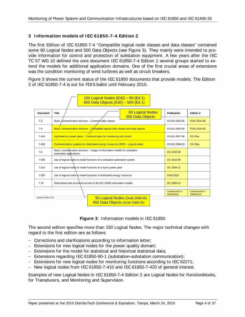
3 Information models of IEC 61850-7-4 Edition 2
The first Edition of IEC 61850-7-4 “Compatible logical node classes and data classes” contained some 90 Logical Nodes and 500 Data Objects (see Figure 3). They mainly were intended to pro-vide information for control and protection of substation equipment. A few years after the IEC TC 57 WG 10 defined the core document IEC 61850-7-4 Edition 1 several groups started to ex-tend the models for additional application domains. One of the first crucial areas of extensions was the condition monitoring of wind turbines as well as circuit breakers.
Figure 3 shows the current status of the IEC 61850 documents that provide models. The Edition 2 of IEC 61850-7-4 is out for FDIS ballot until February 2010.
Document Title Publication Edition 2
7-3 Basic communication structure – Common data classes IS Ed1:2003-05 FDIS 2010-06
7-4 Basic communication structure – Compatible logical node classes and data classes IS Ed1:2003-05 FDIS 2010-02
7-410 Hydroelectric power plants - Communication for monitoring and control IS Ed1:2007-08 CD 20xx
7-420 Communications systems for distributed energy resources (DER) - Logical nodes IS Ed1:2009-03 CD 20xx
7-5 Basic communication structure – Usage of information models for substationautomation applications DC 2010-08
7-500 Use of logical nodes to model functions of a substation automation system DC 2010-08
7-510 Use of logical nodes to model functions of a hydro power plant DC 2009-12
7-520 Use of logical nodes to model functions of distributed energy resources Draft 2010
7-10 Web-based and structured access to the IEC 61850 information models DC 2009-12
current work in 2009/2010
current work in 2009/2010
updated 2009-12-28 50 Logical Nodes (Draft 2008-05)450 Data Objects (Draft 2008-05)
150 Logical Nodes (Ed2) – 90 (Ed 1)800 Data Objects (Ed2) – 500 (Ed 1)
60 Logical Nodes350 Data Objects
Figure 3: Information models in IEC 61850
The second edition specifies more than 150 Logical Nodes. The major technical changes with regard to the first edition are as follows:
− Corrections and clarifications according to information letter; − Extensions for new logical nodes for the power quality domain; − Extensions for the model for statistical and historical statistical data; − Extensions regarding IEC 61850-90-1 (substation-substation communication); − Extensions for new logical nodes for monitoring functions according to IEC 62271; − New logical nodes from IEC 61850-7-410 and IEC 61850-7-420 of general interest.
Examples of new Logical Nodes in IEC 61850-7-4 Edition 2 are Logical Nodes for Functionblocks, for Transducers, and Monitoring and Supervision.

Monitoring of Power System and Communication Infrastructures based on IEC 61850 and IEC 61400-25
Paper presented at the 2010 DistribuTech Conference & Exposition, Tampa, March 24, 2010 Page 5 of 37
Logical Nodes for Functionblocks
The following Logical Nodes expose information used in Functionblock applications: 1. Counter – FCNT 2. Curve shape – FCSD 3. Generic filter – FFIL 4. Control function output limitation – FLIM 5. PID regulator – FPID 6. Ramp function – FRMP 7. Set-point control function – FSPT 8. Action at over threshold – FXOT 9. Action at under threshold – FXUT An example of a PID loop control with a Logical Node “FPID” representing its attributes (or input and output signals) is shown in Figure 4.
Figure 4: PID Logical Node
Note that IEC 61850 DOES NOT specify the PID loop control algorithm, logig, or function. IEC 61850-7-4 Logical Nodes provide the "interface" or the presentation of the signals, the configu-ration of the object models and the exchange of the values. The Data Object "KP" (Proportional gain) can be set by an ACSI service. Or the Data Object "DAct" (Derivative action) can be read, reported, logged, or sent by a GOOSE message. All Data Objects can be monitored by using the IEC 61850-7-2 service “Reporting” and “Logging”.
Many other new Logical Nodes are included in the second edition of IEC 61850-7-4. There is one crucial area to mention: The new Logical Nodes for sensor (transducer) data. Several of these

Monitoring of Power System and Communication Infrastructures based on IEC 61850 and IEC 61400-25
Paper presented at the 2010 DistribuTech Conference & Exposition, Tampa, March 24, 2010 Page 6 of 37
new and other Logical Nodes have been moved from the Edition 1 of IEC 61850-7-410 (Hydro) to IEC 61850-7-4 Edition 2.
Logical Nodes for Transducers (Sensors)
The following list contains 18 new “T” Logical Nodes for transducers; transducers more or less represent raw values from sensors: 1. Angle – TANG 2. Axial displacement – TAXD 3. Current transformer – TCTR 4. Distance – TDST 5. Liquid flow – TFLW 6. Frequency – TFRQ 7. Generic sensor – TGSN 8. Humidity – THUM 9. Media level – TLVL 10. Magnetic field – TMGF 11. Movement sensor – TMVM 12. Position indicator – TPOS 13. Pressure sensor – TPRS 14. Rotation transmitter – TRTN 15. Sound pressure sensor – TSND 16. Temperature sensor – TTMP 17. Mechanical tension / stress – TTNS 18. Vibration sensor – TVBR 19. Voltage transformer – TVTR 20. Water acidity – TWPH
Most of these Logical Nodes just represent the sampled values from a sensor. The Logical Node for Pressure sensor “TPRS” is shown as an example in Table 1.
Table 1: Logical Node for Pressure sensor
TPRS class
Data object Explanation T M/
O/C
LNName The name shall be composed of the class name, the LN-Prefix and LN-Instance-ID according to IEC 61850-7-2, Clause 22.
Data objects
EEHealth External equipment health O
EEName External equipment name plate O
Measured values
PresSv Sampled value of pressure of media [Pa] C
Settings
SmpRte Sampling rate setting O
Condition C: The data object is mandatory if the data object is transmitted over a commu-nication link and therefore it is visible.

Monitoring of Power System and Communication Infrastructures based on IEC 61850 and IEC 61400-25
Paper presented at the 2010 DistribuTech Conference & Exposition, Tampa, March 24, 2010 Page 7 of 37
All “T” Logical Nodes have a Data Object “EEHealth” that provides a simple status information “green”, “yellow” or “red” of the real underlying sensor (called ExternalEquipment – EE). They have further a Data Object “EEName” which comprises a huge list of mainly optional information that provides general details about the sensor. The external equipment name plate exposes the following information (without further explanation): vendor, hwRev, swRev, serNum, model, lo-cation, name, owner, ePSName, role, primeOper, secondOper, latitude, longitude, altitude, and mrID.
Logical Nodes for Supervision and Monitoring
The Logical Nodes for supervision and monitoring of the Logical Node group “S” comprise also a lot of new models (seven new Logical Nodes): 1. Monitoring and diagnostics for arcs – SARC 2. Circuit breaker supervision – SCBR (new) 3. Insulation medium supervision (gas) – SIMG 4. Insulation medium supervision (liquid) – SIML 5. Tap changer Supervision – SLTC (new) 6. Supervision of Operating Mechanism – SOPM (new) 7. Monitoring and diagnostics for partial discharges – SPDC (new) 8. Power Transformer Supervision – SPTR (new) 9. Circuit Switch Supervision – SSWI (new) 10. Temperature supervision – STMP (new) 11. Vibration supervision – SVBR (new) The new Logical Node “Circuit breaker supervision – SCBR” (see Table 2) for example comprises a huge number of new Data Objects that represent a more detailed status of circuit breakers than an “EEHealth” Data Object. These Data Objects of have been defined as part of a new Log-ical Node “SCBR” instead of adding them to the well know Logical Node “XCBR”. For a specific real circuit breaker only a subset of the Data Objects may be applicable. Or there may even be a need to define further Data Objects; this can be done easily according the name space con-cept of IEC 61850-7-1 (which is already defined in Edition 1).
Almost all Data Objects of the “SCBR” are optional. Optional usually means that a vendor of an IEC 61850 compliant device can decide to implement only the mandatory Data Objects – in or-der to be fast on the market and having a standard conformant device (with the minimum of objects). Very often utility people or system integrators are surprised that a device has just a few objects – they would like to have more. It is up to the utilities to request from the vendors to implement more than just the minimum. This is – of course – completely outside the influ-ence of the standardization groups. The Data Objects of the Logical Node “SCBR” are listed in Table 2. These Data Objects have been discussed by several groups of domain experts of switch gears prior to the inclusion into the Edition 2.
In addition to the features build into the measured value models (common data class “MV”; see also the communication services explained further down) there are some crucial Data Objects like “AbrAlm” (Contact abrasion alarm) and “AbrWrn” (Contact abrasion warning) that define a concrete semantic (meaning) of the object. An alarm may be communicated by a GOOSE mes-sage and a software at the subscriber side may act automatically on the receipt of this GOOSE message. The alarm and warning levels are defined in the settings “AbrAlmLev” (Abrasion sum threshold for alarm state) and “AbrWrnLev” (Abrasion sum threshold for warning state). The levels may be configured during device configuration or they may be configured by a communi-cation service (SetDataValues) at runtime.

Monitoring of Power System and Communication Infrastructures based on IEC 61850 and IEC 61400-25
Paper presented at the 2010 DistribuTech Conference & Exposition, Tampa, March 24, 2010 Page 8 of 37
Table 2: Logical Node “Circuit breaker supervision – SCBR”
Status information
OpCntRs Resettable Operation Counter ColOpn Open command of trip coil AbrAlm Contact abrasion alarm AbrWrn Contact abrasion warning MechHealth Mechanical behavior alarm OpTmAlm Switch operating time exceeded ColAlm Coil alarm OpCntAlm Number of operations (modeled in the XCBR) has exceeded
the alarm level for number of operations OpCntWrn Number of operations (modeled in the XCBR) exceeds the
warning limit OpTmWrn Warning when operation time reaches the warning level OpTmh Time since installation or last maintenance in hours
Measured values
AccAbr Cumulated abrasion SwA Current that was interrupted during last open operation ActAbr Abrasion of last open operation AuxSwTmOpn Auxiliary switches timing Open AuxSwTmCls Auxiliary switches timing Close RctTmOpn Reaction time measurement Open RctTmCls Reaction time measurement OpSpdOpn Operation speed Open OpSpdCls Operation speed Close OpTmOpn Operation time Open OpTmCls Operation time Close Stk Contact Stroke OvStkOpn Overstroke Open OvStkCls Overstroke Close ColA Coil current Tmp Temperature e.g. inside drive mechanism
Settings
AbrAlmLev Abrasion sum threshold for alarm state AbrWrnLev Abrasion sum threshold for warning state OpAlmTmh Alarm level for operation time in hours OpWrnTmh Warning level for operation time in hours OpAlmNum Alarm level for number of operations OpWrnNum Warning level for number of operations
It is likely that new vendors of IEC 61850 conformant devices will specialize in the domain of condition monitoring and offer more possibilities than traditional vendors. The trend is quite ob-vious: There are a lot of new solutions for monitoring one or the other part of the process that will hid the road in 2010. The monitoring operation usually does not have a direct link to the au-tomation and protection. It is lees critical than protection functions and devices. Most equipment in the electrical system (mainly at distribution level) is not monitored at all today – operators are quite “blind” on what’s going on in distribution networks. With the event of Smart Grids (or Smarter Grids) this is likely to change dramatically.

Monitoring of Power System and Communication Infrastructures based on IEC 61850 and IEC 61400-25
Paper presented at the 2010 DistribuTech Conference & Exposition, Tampa, March 24, 2010 Page 9 of 37
4 Information models of IEC 61850-7-410 Edition 2 for Monitoring
The Standard IEC 61850-7-410 Edition 1 “Communication networks and systems for power utili-ty automation – Part 7-420: Basic communication structure – Hydropower plant logical nodes” defines some 60 Logical Nodes and 350 Data Objects for various hydropower plant applications.
The Logical Nodes in IEC 61850-7-410 Edition 1, that where not specific to hydropower plants (mainly those that represent transducers, supervision and monitoring information), have been moved to Edition 2 of IEC 61850-7-4 and they will be removed from Edition 2 of IEC 61850-7-410. Most of the modeling examples and background information that was included in IEC-61850-7-410 Edition 1 will be transferred to a technical report TR 61850-7-510.
Edition 2 of IEC 61850-7-410 will include additional general-purpose and supervision and moni-toring Logical Nodes, not included in IEC 61850-7-4 (Edition 2), but required in IEC 61850-7-410 in order to represent the complete control and monitoring system of a hydropower plant.
The following Logical Nodes for supervision and monitoring (Group “S”) have been specified for Edition 2 of IEC 61850-7-410: 1. Supervision of media flow – SFLW 2. Supervision of media level – SLEV 3. Supervision of the position of a device – SPOS 4. Supervision media pressure – SPRS Each of these Logical Nodes comprises measured values, status information and settings.
Details are still under discussion in IEC TC 57 WG 18 which is responsible for the Edition 2 of IEC 61850-7-410.
5 Information models of IEC 61850-7-420 Edition 1 for Monitoring
The Standard IEC 61850-7-420 Edition 1 “Communication networks and systems for power utili-ty automation – Part 7-420: Basic communication structure – Distributed energy resources logi-cal nodes” defines some 50 Logical Nodes and 450 Data Objects for various DER domains.
Most Logical Nodes have some status information and measurements that can be used for moni-toring. They are usually not defined in separate “S” Logical Nodes.
IEC 61850-7-420 defines the following specific Logical Nodes that are intended to provide spe-cial measurements for monitoring various physical processes: 1. Temperature measurements – STMP 2. Pressure measurements – MPRS 3. Heat measurement – MHET 4. Flow measurement – MFLW 5. Vibration conditions – SVBR The details of the Logical Nodes could be found in IEC 61850-7-420. One example is shown in the following example.
The crucial Data Objects of the Logical Node “MFLW” (Flow measurement ) are listed in Table 3. These models are more comprehensive than those that will be defined in IEC 61850-7-4 Edition 2; they may be used for any other application domain as well.
One of the crucial benefits of IEC 61850 is this: Which Data Object is ever missing in any Logical Node, it could be defined as an extension. IEC 61850-7-1 defines the rules for defining new Log-ical Nodes, new Data Objects or even new common data classes. The concept is called the “name space concept”.

Monitoring of Power System and Communication Infrastructures based on IEC 61850 and IEC 61400-25
Paper presented at the 2010 DistribuTech Conference & Exposition, Tampa, March 24, 2010 Page 10 of 37
Table 3: Logical Node “Flow measurement – MFLW”
Measured values
FlwRte Volume flow rate FanSpd Fan or other fluid driver speed FlwHorDir Flow horizontal direction FlwVerDir Flow vertical direction MatDen Material density MatCndv Material thermal conductivity MatLev Material level as percent of full FlwVlvPct Flow valve opening percent
Controls
FlwVlvCtr Set flow valve opening percent FanSpdSet Set fan (or other fluid driver) speed
Metered values
MtrVol Metered volume of fluid since last reset
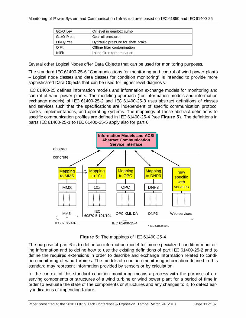
6 Information models of IEC 61400-25 for Monitoring
Some Data Objects are already defined in the current published standard IEC 61400-25-2 “Communications for monitoring and control of wind power plants – Information models”. The Logical Node Wind turbine transmission information (WTRM) comprises the Data Objects that represent wind turbine (mechanical) transmission information. The data represent usual trans-mission topology, consisting of a slow speed shaft, multistage gearbox, a fast shaft and a (hy-draulically driven) mechanical brake. In case of a divergent transmission topology (e.g. direct drive, single stage gearbox) or different mounted equipment (e.g. sensors, electromechanical brake), users are free to adapt or extend the data classes. Table 4 shows the Logical Node “WTRM” of the standard IEC 61400-25-2 published in January 2007. Most of the Data Objects of this Logical Node provide monitoring information of the transmission system.
Table 4: Logical Node “WTRM”
Data object Description Status information BrkOpMod Status of shaft brake LuSt Status of gearbox lubrication system. FtrSt Status of filtration system ClSt Status of transmission cooling system HtSt Status of heating system OilLevSt Status of oil level in gearbox sump OfFltSt Status of offline filter InlFltSt Status of inline filter Measured values TrmTmpShfBrg1 Measured temperature of shaft bearing 1 TrmTmpShfBrg2 Measured temperature of shaft bearing 2 TrmTmpGbxOil Measured temperature of gearbox oil TrmTmpShfBrk Measured temperature of shaft brake (surface) VibGbx1 Measured gearbox vibration of gearbox 1 VibGbx2 Measured gearbox vibration of gearbox 2 GsLev Grease level for lubrication of main shaft bearing
Monitoring of Power System and Communication Infrastructures based on IEC 61850 and IEC 61400-25
Paper presented at the 2010 DistribuTech Conference & Exposition, Tampa, March 24, 2010 Page 11 of 37
GbxOilLev Oil level in gearbox sump GbxOilPres Gear oil pressure BrkHyPres Hydraulic pressure for shaft brake OfFlt Offline filter contamination InlFlt Inline filter contamination
Several other Logical Nodes offer Data Objects that can be used for monitoring purposes.
The standard IEC 61400-25-6 “Communications for monitoring and control of wind power plants – Logical node classes and data classes for condition monitoring” is intended to provide more sophisticated Data Objects that can be used for higher level diagnosis.
IEC 61400-25 defines information models and information exchange models for monitoring and control of wind power plants. The modeling approach (for information models and information exchange models) of IEC 61400-25-2 and IEC 61400-25-3 uses abstract definitions of classes and services such that the specifications are independent of specific communication protocol stacks, implementations, and operating systems. The mappings of these abstract definitions to specific communication profiles are defined in IEC 61400-25-4 (see Figure 5). The definitions in parts IEC 61400-25-1 to IEC 61400-25-5 apply also for part 6.
Information Models and ACSIAbstract Communication
Service Interface
Information Models and ACSIAbstract Communication
Service Interface
Mappingto MMS
abstract
concrete
MMS
Mappingto OPC
OPC
Mappingto 10x
10x
OPC XML DAIEC 60870-5-101/104MMS
Mappingto DNP3
DNP3
newspecific
webservices
DNP3 Web services
IEC 61850-8-1 IEC 61400-25-4
*
* IEC 61850-80-1
Figure 5: The mappings of IEC 61400-25-4
The purpose of part 6 is to define an information model for more specialized condition monitor-ing information and to define how to use the existing definitions of part IEC 61400-25-2 and to define the required extensions in order to describe and exchange information related to condi-tion monitoring of wind turbines. The models of condition monitoring information defined in this standard may represent information provided by sensors or by calculation.
In the context of this standard condition monitoring means a process with the purpose of ob-serving components or structures of a wind turbine or wind power plant for a period of time in order to evaluate the state of the components or structures and any changes to it, to detect ear-ly indications of impending failure.

Monitoring of Power System and Communication Infrastructures based on IEC 61850 and IEC 61400-25
Paper presented at the 2010 DistribuTech Conference & Exposition, Tampa, March 24, 2010 Page 12 of 37
Condition monitoring is most frequently used as a Predictive or Condition-Based Maintenance technique (CBM). However, there are other predictive maintenance techniques that can also be used, including the use of the Human Senses (look, listen, feel, smell) or Machine Performance Monitoring techniques. These could be considered to be part of the condition monitoring.
Condition monitoring techniques that generate information to be modeled include, but are not limited to techniques such as:
− Vibration measurements and analysis, − Oil debris analysis, − Temperature measurement, and − Strain gauge measurement.
Components and structures can be monitored by using automatic instrumentation as well as us-ing a manual process.
The condition monitoring functions may be located in different physical devices. Some infor-mation may be located in a turbine controller device (TCD) while other information may be lo-cated in an additional condition monitoring device (CMD). Various actors may request to ex-change data located in the TCD or CMD. A SCADA device may request the information from a TCD or CMD; a CMD may request information from a TCD and vice versa. The information ex-change between any two devices requires the use of information exchange services defined in IEC 61400-25-3 or added in part 6.
The use case of having the condition monitoring functions located in the turbine controller de-vice is a special use case. That use case does not require information exchange services for the information exchange between the condition monitoring functions and the turbine controller functions. The case of having separate devices is the more comprehensive use case. This is used as the typical topology in this part of the standard. The special case of both functions in one device could be derived from the most general use case.
It may also be required to build a hierarchical model of automatic turbine controller and condi-tion monitoring devices/functions. A simple condition monitoring device (CMD; providing meas-ured values and status information and very basic monitoring capabilities). This CMD may re-trieve information from the underlying CMD or TCD and may further process and analyze the measured values and status information.
In condition monitoring systems predefined triggers are applied to initiate a sequence of events, for example issuing an alarm to the local SCADA system or sending a message to a monitoring centre in order to prevent further damage on components or structures. In general such mes-sages can be used by a Condition Monitoring Supervision function to generate actionable infor-mation which can be used by a service organization to create work orders and initiate actions. Figure 6 illustrates the information chain of a system using condition monitoring to perform con-dition based maintenance.
Figure 6 illustrates how data are refined and concentrated through the information chain, ending up with the ultimate goal of condition based maintenance – actions to be performed via issuing work orders to maintenance teams.

Monitoring of Power System and Communication Infrastructures based on IEC 61850 and IEC 61400-25
Paper presented at the 2010 DistribuTech Conference & Exposition, Tampa, March 24, 2010 Page 13 of 37
Data AcquisitionPrimary Alarm and Warning reporting
Trending AnalysisSecondary Alarming and Warning reporting
Data Storage
Alarm ManagementAdvanced Diagnosis
Data MiningOperational Reporting
Work Orders
Info
rmat
ion
Info
rmat
ion
Dat
a R
educ
tion
Ref
inem
ent o
f Inf
orm
atio
n
Primary Condition Monitoring
Secondary Condition Monitoring
Condition Monitoring Supervision
Service Management
Sco
pe o
f IE
C 6
1400
-25-
6
Info
rmat
ion
Figure 6: The information chain of condition based maintenance
Figure 6 shows the scope of IEC 61400-25-6 and the typical information chain of condition mon-itoring systems. The local (primary) part of the chain could be named as condition monitoring localized in the wind turbine and the wind farm SCADA system, but the local functionality can vary from system to system. The centralized (secondary) data retrieval performed by for exam-ple a control centre system is often named as a back-office system. The decreasing sizes of the boxes illustrate the data reduction and the transformation of data into more useful information with an enhanced value.
The FDIS (Final Draft International Standard) of part IEC 61400-25-6 is expected to be available in early 2010.
7 Communication services for monitoring
The part IEC 61850-7-2 (ACSI – Abstract communication service interface) and IEC 61400-25-3 define the basics for information models and services and part IEC 61850-7-4 and IEC 61400-25-2 (Logical Nodes and Data Objects) defines concrete information models (the Data Objects that represent the values to be monitored). It is crucial to understand that the standards IEC 61850 and IEC 61400-25 do not define new process data – the standards assign useful names and types to real-world data. These names are valid internationally.
The ACSI provides the following basic definitions we need for monitoring:

Monitoring of Power System and Communication Infrastructures based on IEC 61850 and IEC 61400-25
Paper presented at the 2010 DistribuTech Conference & Exposition, Tampa, March 24, 2010 Page 14 of 37
− Logical Nodes are used as containers of any information (Data Objects) to be monitored, − Data Objects are used to designate useful information to be monitored, − Retrieval (polling) of the values of Data Objects (GetDataObjectValues), − Send events from a server device to a client (spontaneous Reporting), − Store historical values of Data Objects (logging), − Exchange sampled values (current, voltages and vibration values), − Exchange simple status information (GOOSE), and − Recording functions with COMTRADE files as output.
These basic definitions are explained in the following with regard to the use case “monitoring”.
Logical Nodes
Many Logical Nodes are explicitly defined to represent a list of Data Objects that relate to meas-urements like temperature, pressure, level, gas density, etc. Many other logical nodes are a mix of controllable Data Objects, objects for settings, protection, and so on.
An example of a Logical Node comprising only monitoring information is the Logical Node “Cir-cuit breaker wear supervision” (SCBR) of the draft edition 2 of IEC 61850-7-4 is shown in Table 5 (this and the following Logical Node tables are just showing an excerpt of Data Objects).
Table 5: Circuit breaker wear supervision Logical Node (SCBR)
Data object Description Status information Col1Opn Open command of trip coil 1 Col2Opn Open command of trip coil 2 (usually as backup protection coil) AbrAlm Contact abrasion alarm AbrWrn Contact abrasion warning Measured values AccAbr Cumulated abrasion coefficients TripA Current that was interrupted during last open operation ActAbrCoef Abrasion coefficient of last open operation Settings AbrAlmLev Abrasion coefficient sum threshold for alarm state AbrWrnLev Abrasion coefficient sum threshold for warning state
Operating a breaker and especially tripping a short circuit causes always some abrasion (or ero-sion) of the breaker contacts. The supervision relates to a single phase since each phase has its own contact.
The first seven Data Objects can be used for monitoring purposes; the last two are used for set-tings limits. The communication services applicable are explained below.
Data Objects
There are several categories of Data Objects that provide various aspects of the monitoring pro-cess:
− Status information (single or double point information), − Measured information (analogue values measured or calculated, and − Settings (set ratings or limits for monitoring)
The standards related to IEC 61850 define hundreds of Data Objects of these categories.
Some basic aspects with regard to monitoring are explained in the following paragraphs:
Monitoring of Power System and Communication Infrastructures based on IEC 61850 and IEC 61400-25
Paper presented at the 2010 DistribuTech Conference & Exposition, Tampa, March 24, 2010 Page 15 of 37
Status information: In most cases there is a need to provide several details of the status. IEC 61850-7-3 provides these attributes by, e.g., the common data class SPS (single point status as defined in IEC 61850-7-3):
− stVal BOOLEAN TrgOp=dchg − q Quality TrgOp=qchg − t TimeStamp
Any change of the value of the status with the standard name “stVal” can be used to trigger a report (comprising the values for stVal, q and t) to be sent to clients or to trigger to log the val-ues of stVal, q and t to one or multiple logs. It is also possible that a client reads these values (stVal, q and t) at any time to get the values of the last change or the current value.
These values may also be used to be sent as content of a GOOSE messages. GOOSE messages are sent by multicast to any IEDs (Intelligent Electronic Device) connected to the same subnet-work. Even a sampled value message may sent the values (stVal, q and t) continuously with the same rate (e.g. 4 kHz) as the current and voltage samples from CTs and VTs.
Independent of the use of reporting, logging, GOOSE, or sampled value exchange, the data to be exchanged has to be specified by a DataSet. A DataSet contains a list of references to Data Objects and parts of it (the so-called functionally constraint data, FCD, or data attributes, FCDA).
A DataSet may comprise several status information and a few measurements for example.
Measured values: IEC 61850-7-3 provides attributes for measured values. The most common class is the common data class MV (measured value) with the following attributes:
− instMag AnalogueValue − mag AnalogueValue TrgOp=dchg − range ENUMERATED TrgOp=dchg − q Quality TrgOp=qchg − t TimeStamp − units Unit − db INT32U − zeroDb INT32U − sVC ScaledValueConfig − rangeC RangeConfig
Any change of the magnitude value (with the standard name “mag”) can be used to trigger a report (of mag, range, q and t) to be sent to clients or to trigger to log these values to one or multiple logs. It is also possible that a client reads these values at any time to get the last change. The values may also be used for other services like GOOSE.
The use of mag (a deadband or filtered value) and range in conjunction with reporting and log-ging is explained below.
The attribute units, db, sVC and rangeC are used to configure the engineering unit (e.g., V for Volt), the multiplier (M for Mega), the deadband value for filtering the analogue value, the scale factor and offset (for integer values) and the range configuration. Those attributes that have a impact on the monitoring of measured value are explained below.
Statistical and historical statistical information
Measurement Data Objects usually (in Edition 1) refer to RMS (root mean square) values or just current values, provided at the time when they have been measured. In many applications there is a need to refer also to statistical values of a measurement, e.g., maximum value of an hour or

Monitoring of Power System and Communication Infrastructures based on IEC 61850 and IEC 61400-25
Paper presented at the 2010 DistribuTech Conference & Exposition, Tampa, March 24, 2010 Page 16 of 37
15 minutes interval. The statistical values require some minor extensions of the first edition of IEC 61850-7-x. The standard IEC 61400-25-2 has already published the solution for statistical data.
In many application domains such as wind power plants, it is required to provide additional in-formation of a basic analogue value:
− Statistical information (for example, minimum value calculated for a specified time period, for example, minimum value of last 1 hour)
− Historical statistical information (for example, log of minimum values of the sequence of values calculated above, for example, last 24 hourly values)
This additional information may be derived from the basic analogue values. It may be the only information provided – depending on the application requirements.
The models for the statistical and historical statistical data are explained conceptually in Figure 7.
On the left hand side are the basic data representing the cur-rent values (PRES), i.e. some in-stantaneous analogue (or integer) values that are contained in the logical node instance XXYZ.
The upper half depicts the method defined for statistical values. The first example is the in-stance XXYZ1 of the logical node class XXYZ. The analogue values represent the calcu-lated maximum values derived from the instance XXYZ. The logical node XXYZ1 has special setting data that indicate that the values are maximum values and that the calculation method is “peri-odic”. The period starts after a start command or by local means. At the end of the period the calculated maximum values of the instance XXYZ1 are overwritten by the new values.
The maximum values can be used to calculate the minimum maximum values in – of course – a much longer period than for the maximum calculation in XXYZ1. The instance XXYZ2 may repre-sent the minimum value of the max value of the last 10 days.
Setting parameters other than PERIOD may be used to specify calculation modes. A calculation mode set to TOTAL means that the calculated maximum values are calculated since the first start of the device or of the involved application. A calculation mode set to SLIDING means that the calculated maximum values are calculated over a sliding window whose width can be set by means of a special interval type setting (e.g. hour, day, week).
The lower part of the figure shows the conceptual model of the historical statistical data. In this model the calculated val-ues (in this case the maximum values with calculation mode set to PE-RIOD) are stored in sequence in a log. The calcula-tion in the example starts at midnight of 2004-10-03. The in-terval is 1 h. After that first hour the first log entry is written. After the se-cond hour the second entry contains the value of the second hour. After five (5) hours the log contains the values of the last three hours (intervals 02-03, 03-04, 04-05).

Monitoring of Power System and Communication Infrastructures based on IEC 61850 and IEC 61400-25
Paper presented at the 2010 DistribuTech Conference & Exposition, Tampa, March 24, 2010 Page 17 of 37
LN XXYZ
Statistical historicalvalues
Instantaneous values
Calculate max and store in log
Analogue dataAnalogue data
PRES
Log
Analogue dataAnalogue dataAnalogue data
Analogue dataAnalogue dataAnalogue data
MAX
start command (ClcStr set)e.g. midnight 2004-10-03
periode.g. 1 h
period period
LN XXYZ1Analogue dataAnalogue data
Calculatemax andoverwrite
MAX
periode.g. 10 h
period period
start command (ClcStr not set)
05:00
04:00
03:00period period
01 02 03 04 0500
curre
nt
log with 3 entries
Statistical values
LN XXYZ2Analogue dataAnalogue data
Calculatemin andoverwrite
MIN
Statistical values
QueryLogByTime
QueryLogAfter
03:00 - 05:00
after 03:00
Trigger optiontrgOp= dchg
Calculation mode is PERIOD
total
Calculation mode is TOTAL
Sliding window
Calculation mode is SLIDING
start command (ClcStr not set)
Since the 1rst startof the device/application
e.g. one week
Figure 7: Statistical and Historical Statistical Data Objects (1)
The statistical data model is based on the calculation of analogue values contained in other logi-cal nodes. The top logical node LN XXYZ in Figure 2 refers to three technologi-cal logical nodes of the same Type (for example MMXU). The top logical node (LN XXYZ) represents the instanta-neous measured values. The second and third logical nodes are the statistical logical nodes, i.e., the logical nodes that represent the calculated values (LN XXYZ1 represents the MIN values, the LN XXYZ2 the MAX values).
The two logical nodes on the left of the bottom in Figure 2 (XXYZ1 and XXYZ2) represent mini-mum (MIN) and maxi-mum (MAX) values of the analogue data represented in the top logical node (XXYZ). The two logical nodes make use of the setting data ClcSrc (calculation source). The common data class of ClcSrc is ORG, “object reference setting group” and is used to refer-

Monitoring of Power System and Communication Infrastructures based on IEC 61850 and IEC 61400-25
Paper presented at the 2010 DistribuTech Conference & Exposition, Tampa, March 24, 2010 Page 18 of 37
ence the source logical node for the calculation. For both logical nodes, ClcSrc has the value XXYZ. Each logical node with analogue data can be used as a source. Addi-tionally, they have the data ClcStr (calculation start) and ClcExp (calculation expired) and the setting data ClcPerms (calculation period), ClcSrc (calculation source), and ClcMod (calculation mode).
With the settings ClcMod, ClcMthd, ClcPer and ClcSrc, the behavior of the logical node can be controlled. For periodic calculation, the “event” ClcExp set to TRUE can be used as an event to report the new value (the statistical value) by the re-port control block or it may be logged as historical statistical data for later retrieval.
The data names of the “Data” in all logical nodes shown Figure 8 are the same, i.e., in all three logical nodes. The data are contained in different logical node instances (XXYZ, XXYZ1, and XXYZ2). These result in the following refer-ences: XXYZ.Data1, XXYZ1.Data1, and XXYZ2.Data1.
LN XXYZClcMth [PRES]Data1 MVData2 WYE
LOG
log entry
Statisticalhistorical values
Special instance of a log
LN XXYZ1
ClcMth [MIN]ClcPerms INGClcSrc ORGClcExp SPSClcStr SPCData1 MVData2 WYE
LN XXYZ2
ClcMth [MAX]ClcPerms INGClcSrc ORGClcExp SPSClcStr SPCData1 MVData2 WYE
Statistical values
For analogue data of LN XXYZ calculate the corresponding statistical values (all data or subset) and store them in the corresponding data of LN# at the end of the calculation period (ClcPerms) of the LN#
Instantaneous values
store (log entry)
calc
ulat
e
calc
ulat
e
For analogue data of LN XXYZ# store the corresponding statistical values in a log at the end of the calculation period
Clc
Src
log entrylog entry
Clc
Src
Figure 8: Statistical and Historical Statistical Data Objects (2)
Settings: Setting Data Objects are used to set specific val-ues for limits and other purposes. The purpose is usually de-fined with the semantic of a Data Object.
In the example of the Logical Node SCBR the two settings are used to monitor when to change status values of the warn-ing AbrWrn and the alarm Data Object AbrAlm. These Data Objects are single point status objects that can be used by the various communication services.
Retrieve (poll) the values of Data Objects
Any Data Object, any part of it and any group of them (optionally through a DataSet) can be read from a client. The corresponding services are GetDataValues and GetDataSetValues.
A DataSet may be defined by the service CreateDataSet (online), during configuration, or it may be built in.
Send events from a server device to a client (spontaneous Reporting)

Monitoring of Power System and Communication Infrastructures based on IEC 61850 and IEC 61400-25
Paper presented at the 2010 DistribuTech Conference & Exposition, Tampa, March 24, 2010 Page 19 of 37
Reporting is one of the most powerful service models in IEC 61850. It allows to configure the reporting behavior of the server device in a wide range of possibilities.
The basic concept of reporting is that values to be reported are specified by a DataSet object. The DataSet is a list of references to the objects to be reported; each referenced object is called a member of the DataSet. If a change of a value of one of the members happens the server creates a report message and sends the new value to the corresponding client. The change is also called a trigger – to trigger sending a report.
The trigger options are defined in the Data Objects (in Logical Nodes). There are, for example, two trigger options (data value change and quality value change) defined for each status Data Object derived from the common data class SPS:
SPS (single point status):
− stVal BOOLEAN TrgOp=dchg − q Quality TrgOp=qchg − t TimeStamp
The two Data Objects of the Logical Node SCBR (from above) are derived from the common da-ta class SPS:
“AbrAlm” – Contact abrasion alarm and “AbrWrn” – Contact abrasion warning
If the cumulated abrasion coefficients “AccAbr” has reached the value of the “AbrWrnLev” (as configured by “AbrWrnLev” -abrasion coefficient sum threshold for warning state) the value of “AbrWrn” changes and can be reported if the object is a member of the corresponding DataSet.
Setting Data Objects are used to set specific values for limits and other purposes. The purpose is usually defined with the semantic of a Data Object.
In the example of the Logical Node “SCBR” the two settings are used to monitor when to change status values of the warning “AbrWrn” and the alarm Data Object “AbrAlm”. These Data Objects are single point status objects that can be used by the various communication services.
The example has shown that any analog value (measurement or calculated value) can be moni-tored for limit violations. This approach of defining Data Objects for the analogue value “Ac-cAbr”, the limit configurations “AbrWrnLev” and “AbrAlm-Lev” and the warning “AbrWrn” and alarm “AbrAlm” is quite often used in the Logical Nodes in edition 2 of IEC 61850-7-4 and in other documents.
The measured value common data class “MV” contains already some mechanisms to monitor analogue values.
IEC 61850-7-3’s common data class MV (measured value) has the following values with regard to reporting:
− mag AnalogueValue TrgOp=dchg − range ENUMERATED TrgOp=dchg − q Quality TrgOp=qchg − t TimeStamp − db INT32U − rangeC RangeConfig
The use of the attributes mag and range are shown in Figure 9 and Figure 10.

Monitoring of Power System and Communication Infrastructures based on IEC 61850 and IEC 61400-25
Paper presented at the 2010 DistribuTech Conference & Exposition, Tampa, March 24, 2010 Page 20 of 37
Time
Cumulated abrasion coefficients(AccAbr )[AnalogueValue]
SCBR.AbrWrn (stVal=TRUE)
configuration
SCBR
SCBR.AbrWrn
SCBR.AbrWrnLev
SCBR.AbrAlmLev
SCBR.AbrWrn (stVal=FALSE)
trigger option = data change
Figure 9: Deadband Filtering and Reporting (logging)
The analog value “AccAbr” is monitored for relative changes configured by “db” (deadband con-figuration). The deadband configuration specifies a relative change in per cent of the whole val-ue range: Min to Max. In our case the value is 10 per cent. Any change of the value by +/10 per cent issues a trigger that can be used to report or log the new value.
The deadband configuration value can be configured during engineering, IED configuration, or online with the SetData-Value service. The smaller the value the more reports may be generat-ed. It is up to the system integrator or operator (later on) to make sure that the whole system is configured in a way that not too many reports are generated. If for thousands of Data Objects the configuration parameter db is very small and the change rate of the values is high then it could happen that the IEDs and the network are flooded. Be aware everything is limited!

Monitoring of Power System and Communication Infrastructures based on IEC 61850 and IEC 61400-25
Paper presented at the 2010 DistribuTech Conference & Exposition, Tampa, March 24, 2010 Page 21 of 37
RangeConfig:
min lLim llLim = 0
Maintenance required
hhLim = 70
h, t
Reports from server to client(or store entries into IED log)
max,t
FailureMaintenancedemanded
hh, t
max = 120
Range: normal high high-high max
hLim = 55Good
Time
AnalogueValueAccAbr
instMag
Figure 10: Range monitoring and reporting (logging)
The range monitoring uses the limits specified by the range configuration values for min, llLim, lLim, hLim, hhLim and max. Each time the analog value AccAbr crosses one of these limits a trigger is issued. The triggers can be used to report the analog value with the range value min, low-low, low, normal, high, high-high, and max. In addition to these two values the quality in-formation q and timestamp t can be communicated with the report. Instead or in addition to the report the values may be placed into a log.
The meaning of the range values can de defined by the application. In the example it is defined as good, maintenance required, maintenance demanded, and failure. This approach (which is build-in in each analog value derived from the common data class “MV”) is different to the ap-proach discussed earlier with the warning and alarm Data Objects and the configuration of the two limits as Data Objects. There is one difference: the Data Objects “AbrAlm” (Contact abra-sion alarm) and “AbrWrn” (Contact abrasion warning) represent already a semantic. The two Data Objects can easily be used for GOOSE messaging to trigger an automatic function, e.g. to block operation or to control something in the substation.
A comprehensive modeling approach for monitoring of analog values is expected to be written by IEC TC 57 WG 10. This could be used for modeling monitoring of analog values in future ap-plications. It is the freedom of the modelers to model the monitoring function one way or the other. All possibilities defined in the various standards today are conformant to IEC 61850 in general.
Store historical values of Data Objects (logging)
The logging of values of members of a DataSet is exactly the same as the reporting – except that the values are stored in a local buffer (the log – a circular buffer) and that clients have to initiate queries to retrieve logged data values.
The query log service is simple and straight forward: A client specifies the log to be queried, a starting time and ending time, a start time, or an ending time. In the first case all values stored between the two times are transmitted, in the second case all values after the start time are provided and in the third case all values before the ending time will be sent to the client.

Monitoring of Power System and Communication Infrastructures based on IEC 61850 and IEC 61400-25
Paper presented at the 2010 DistribuTech Conference & Exposition, Tampa, March 24, 2010 Page 22 of 37
For different applications it is recommended to think about how to best configure the logging: one log or multiple logs. A DataSet which causes frequent changes that may be logged for a short period (e.g., one day) may use a separate log. Because other Data Objects (not frequently changing) in another DataSet may have to be logged for a year or more. Putting these two streams in one log would cause the low frequent values being overwritten by the high speed values.
Be aware that reporting and especially logging is now migrating from control center SCADA sys-tems down to the IED level. The functions reporting and logging are providing are well known – but usually implemented in SCADA systems; often on top of RTUs (remote terminal units).
Exchange of sampled values (SV)
The sampled value exchange mechanism has been defined in IEC 61850-7-2 and IEC 61850-9-2 for replacing the many wires carrying analog signals of voltage and current measurements. The samples to be transmitted are defined by a DataSet. A DataSet may contain analog and any other type of data, e.g., status values.
For the use of sampled value exchange in so-called Merging Units (MU) the UCA IUG (UCA In-ternational Users Group) has defined an implementation guide “9-2LE”. This guide provides a set of concrete settings for the DataSet and the control block. The DataSet comprises a fixed set of four currents and four voltages. Two sampling rates are defined: 80 samples/period for pro-tection and 256 samples/period for metering. First Merging Units are available.
The sampled value exchange method can also be used for the high speed transmission of vibra-tion data. Think of a huge hydro power plant with some 50 generators. Each and every set of generator and turbine has a lot of sensors that monitor the turbine, generator, and other com-ponents. There is now way to continuously record all samples of vibration sensors. The vibration sensor cold trigger a report sent to the maintenance department indicating a warning level. The maintenance people can now start a sampled value control block to send high speed samples from the field up to the office. At the subscriber of the sample stream there could be a analyzing tool that does some online analysis of the sample stream as it arrives. After some time of analy-sis the publisher may be disabled sending a high frequency stream of samples.
Exchange simple status information (GOOSE)
GOOSE (Generic Object Oriented Substation Event) is used to reliably distribute events very fast in the whole substation (subnetwork). The values to be sent are also specified by a DataSet. The DataSet members may be status information or any other values. After a change of any member of the DataSet the GOOSE message is sent immediately and repeated in a very high frequency. After several repetitions the frequency turns down to a low value (may be every 100 ms). Every 100 ms the receiver (subscriber) can expect new GOOSE message.
If the subscriber does no receive the message after 100 ms, it can expect that the sender (pub-lisher) or the communication network have a serious problem. With that mechanism it is possi-ble to monitor the publisher and communication system continuously. This is not possible in to-day’s wire based exchange of status information.
Recording functions with COMTRADE files as output
The recording functions are defined in IEC 61850-7-4 by a set of Logical Nodes included in the group R – protection related Logical Nodes. They are used to model typical (and well known) re-cording functions in different devices that have (already!) recording capabilities. The recording mechanisms are NOT defined in IEC 61850.

Monitoring of Power System and Communication Infrastructures based on IEC 61850 and IEC 61400-25
Paper presented at the 2010 DistribuTech Conference & Exposition, Tampa, March 24, 2010 Page 23 of 37
RDRE is a Logical Node representing the acquisition functions for voltage and current wave forms from the sensors (CTs and VTs), and for position sensors (usually binary inputs). Calcu-lated values such as frequency, power and calculated binary signals can also be recorded. “RDRE” is used also to define the trigger mode, pre-trigger time, post-trigger time, pre-fault, post-fault, etc. attributes of a disturbance-recording function.
The Logical Node “RADR” is used to represent a single analog channel, while “RBDR” is used for the binary channels. Thus the disturbance recording function is modeled as a logical device with as many instances of “RADR” and “RBDR” Logical Nodes as there are analog and binary chan-nels of the real recorder function available.
8 RWE R&D Process Bus Project
The IEC Standard 61850 is usually used for station and bay level communication. The standard comprises also a digital communication with the process level. This allows to integrate primary substation equipment, in particular electronic instrument transformers in a standardized way in-to the digital communication of the substation automation system (SAS).
RWE (second biggest German utility) has launched a multi-vendor project with the objective of collecting experience with this new process bus technology in a real 380/110 kV substation envi-ronment. An already existing 380/110 kV power transformer and its related bays were equipped with the new process bus technology in parallel to the existing active SAS. Two non-conventional CTs and VTs have been added to the primary equipment. The digital interface of an instrument transformer is the so called “merging unit”. Samples from conventional instru-ment transformers using the 100V/1A interface can also communicate using a merging unit as a sample value publisher. Thus a merging unit operates as a decentralized A/D-converter.
The communication network consists of two fully redundant ring busses. Several devices are connected: merging units, protection devices, bay controllers, electronic circuit breaker devices, a voltage controller, a tap changer controller, power transformer monitoring, an HMI and the gateway to the existing SAS.
The topology is based on the so-called "9-2LE" (light edition) published by the UCA users group based on IEC 61850-9-2 Edition 1. According to the specification the data volume per merging unit is about 5 MBit/s for 50 Hz and about 6 MBit/s for 60 Hz comprising one set of 3-phase cur-rent and voltage samples. Other time critical data (e.g. GOOSE messages) and also non time critical data (e.g. file transfer) could be transmitted over the same architecture. Figure 11 shows the topology of the process bus and the substation.
One of the key requirements was the implementation of a transformer monitoring system based on appropriate Logical Nodes and Data Objects as well as a selection of crucial client-server communication services. Additional monitoring information is provided by circuit breaker IEDs.

Monitoring of Power System and Communication Infrastructures based on IEC 61850 and IEC 61400-25
Paper presented at the 2010 DistribuTech Conference & Exposition, Tampa, March 24, 2010 Page 24 of 37
110 kVT412380 kV
MergingUnit
Transf.-Monitoring
OLTCMonitoring CB IED
MergingUnitOLTC IED
samplesno samples
MU
Sensor-data
Station control /Remote control
I >(30 kV)
Disturb.recorder
Measur.
Diff.-Protection
Disturb.recorder
I >Buchholz
Disturb.recorder
Measur.
HMIDistanceSync.
Disturb.recorder
Measur.
TesttoolU-Control
CT/VTalarms
Bay-controller
MUMU
MergingUnit
CB IEDCT/VTalarms
MergingUnit
Bay-controller
Central-unit
IEC 61850
Service PCprinterRemote
service
1 ppsSNTP
Figure 11: Topology of RWE Process Bus project
The Transformer and the load tap changer are monitored by two separate monitoring systems providing each an IEC 61850 server with the appropriate list of Logical Nodes and Data Objects. The transformer monitoring information models are listed in Table 6.
Table 6: Logical Nodes for Transformer Monitoring
LN Data Object MMXU1 Measurements 380 kV MMXU2 Measurements 110 kV MMXU3 Measurements 30 kV YPTR1 Transformer SIML1 Insulation measurement
Transformer SIML2 Insulation measurement circuit
breaker CCGR1 Transformer cooling group 1 CCGR2 Transformer cooling group 2 CCGR3 Transformer cooling group 3 CCGR4 Transformer cooling group 4 CALH1 Summary alarm ZAXN1 Monitoring 3 phases of cooling
group 1

Monitoring of Power System and Communication Infrastructures based on IEC 61850 and IEC 61400-25
Paper presented at the 2010 DistribuTech Conference & Exposition, Tampa, March 24, 2010 Page 25 of 37
ZAXN2 Monitoring 3 phases of cooling group 2
ZAXN3 Monitoring of cooling group 1 ZAXN4 Monitoring of cooling group 2
The process bus interface to the primary equipment provides all crucial information about their status. The key benefit is that all the information from the process level is communicated in a standardized way. Proprietary communication links – using may vendor specific solutions – are replaced by a single solution supported by multiple vendors.
The communication services can be used to retrieve the crucial status information of the primary equipment.
The transformer monitoring system comprises the information models shown in Figure 12 and Figure 13.
Figure 12: Transformer monitoring model for RWE R&D project (1)
Details, e.g., implemented in the SIML1 Logical Node are depicted in Figure 14.

Monitoring of Power System and Communication Infrastructures based on IEC 61850 and IEC 61400-25
Paper presented at the 2010 DistribuTech Conference & Exposition, Tampa, March 24, 2010 Page 26 of 37
Figure 13: Transformer monitoring model for RWE R&D project (2)
Figure 14: Transformer monitoring model for RWE R&D project (3)

Monitoring of Power System and Communication Infrastructures based on IEC 61850 and IEC 61400-25
Paper presented at the 2010 DistribuTech Conference & Exposition, Tampa, March 24, 2010 Page 27 of 37
The server for the transformer monitoring and the merging unit for the current and voltage samples of the transformer measurements are implemented in a standard PLC – Programmable Logic Controller (see Figure 15).
Figure 15: Transformer monitoring and merging unit IEDs
The whole transformer monitoring system is configured through an SCL file defining all needed objects, services, and the binding of the model to the real data of the monitor. The real data values are contained in a database. The binding of the model to the database is accomplished by the so-called <sAddr> attribute in SCL. The binding is automatically done by an interpreter in the IEC 61850 server software.
Once the pilot project is fully functional, protecting, controlling, and monitoring the substation , this is likely the first time where a comprehensive process bus is installed and operating.
9 Web-based and structured access to the IEC 61850 information models
With the use of IEC 61850 in domains outside the substation automation, the number of logical nodes and data objects published is increasing. Today, we have already more than 300 logical nodes defined in different parts of IEC 61850 and IEC 61400-25. There exist many associations between these different documents, but no easy hyperlinked browsing possibility exists. The maintenance of the defined information models always needs to be linked to a new complete document with a large collection of information models.
When experts of new application domains start to use the concepts of IEC 61850 and the exist-ing information models as a base, the domain experts first need to easily identify what already exists. Therefore, it would be preferable to find and browse all information models at one place (preferably at the IEC website).

Monitoring of Power System and Communication Infrastructures based on IEC 61850 and IEC 61400-25
Paper presented at the 2010 DistribuTech Conference & Exposition, Tampa, March 24, 2010 Page 28 of 37
IEC is supporting the publication of standards as databases – the procedure of the standardiza-tion of the information models is defined in Annex J “Procedures for the maintenance of the IEC standards in database format” of the IEC Supplement to ISO/IEC Directives.
It is intended to convert the publication of Logical Nodes and common data classes as being published today in different parts of IEC 61850 and IEC 61400-25 into a web based and struc-tured access solution.
IEC 61850-6, Edition 2 has included in Annex C.2 a XML schema based on SCL type template definitions for the purpose of formally describing IEC 61850 information models as a base to formally document and maintain the models of different IEC 61850 application domains, and fa-cilitate automatic checking of IED data models against these definitions. It is foreseen to de-scribe in the future the standard IEC 61850 information models using that schema. So, in the fu-ture, XML documents shall replace the word documents of the parts IEC 61850-7-3 and IEC 61850-7-4xx as well as IEC 61400-25-2 as the normative documents.
Based on these XML documents, several web-based access possibilities can be implemented. Different users need to be able to access the models through a web-based interface:
− Editors of the standard and working group members need to be able to browse existing mod-els, to add new models and to maintain the existing models.
− National committees need to be able to review the draft models and to comment and vote on the models.
− Any interested people shall be able to browse the semantic and details of the models and to download the formal XML documents of the models.
Note that it will still be possible to automatically derive other representations like pdf and html from the XML files.
An example of a Web-based interface to an IEC standard is the Database for IEC 61360:
http://std.iec.ch/iec61360
As part of that work in a first step a Technical Report IEC 61850-7-10 will be prepared that de-scribes the requirements of the different users and the possible approaches for its implementa-tion.
The web-based access and the procedures involved in maintaining the models shall be described in the report and shall be based on Annex J “Procedures for the maintenance of the IEC stand-ards in database format” of the IEC Supplement to ISO/IEC Directives.
10 Conclusions
In highly automated substations and power plants, almost no limitations exist with regard to make the information from the process (status values, measurements, events on limit violations, any monitoring data) available to any entity that needs the information for controlling, monitor-ing, service, diagnosis, network analyzing, testing, or asset management. The acquisition of any needed process information increases the stability of the system because any failure or trend that may lead to a failure can be made visible.
The electric power delivery system is using IEC 61850, IEC 61400-25, and its extensions in sub-stations, for power quality monitoring applications, for the control and monitoring of wind power plants, control and monitoring of distributed energy resources (DER), and the control and moni-toring of hydro power plants.

Monitoring of Power System and Communication Infrastructures based on IEC 61850 and IEC 61400-25
Paper presented at the 2010 DistribuTech Conference & Exposition, Tampa, March 24, 2010 Page 29 of 37
The condition monitoring possibilities rely on four aspects (standardized in IEC 61850 and IEC 61400-25):
− Standard Data Objects for values to be monitored, − Standard communication services, − Fast and reliable communication protocols, and − Standard configuration language to specify or document the huge amount of information
It is very likely that especially the monitoring applications will be the focus for the next couple of years. Protection and automation of substations is well understood, implemented and used. Many physical aspects are not yet sensed by advanced or even simple sensors.
The standards are providing more and more condition monitoring Data Objects. The services al-low for the exchange of these values in real-time (sampled values and GOOSE) as well in cli-ent/server relations.
11 References
[1] IEC 61850-1, Communication networks and systems in substations – Part 1: Introduction and overview
[2] IEC 61850-2, Communication networks and systems in substations – Part 2: Glossary
[3] IEC 61850-3, Communication networks and systems in substations – Part 3: General re-quirements
[4] IEC 61850-4, Communication networks and systems in substations –- Part 4: System and project management
[5] IEC 61850-5, Communication networks and systems in substations – Part 5: Communica-tion requirements for functions and devices models
[6] IEC 61850-6, Communication networks and systems in substations – Part 6: Configuration description language for communication in electrical substations related to IEDs
[7] IEC 61850-7-1, Communication networks and systems in substations – Part 7-1: Basic communication structure for substation and feeder equipment – Principles and models
[8] IEC 61850-7-2, Communication networks and systems in substations – Part 7-2: Basic communication structure for substation and feeder equipment – Abstract communication service interface (ACSI)
[9] IEC 61850-7-3, Communication networks and systems in substations – Part 7-3: Basic communication structure for substation and feeder equipment – Common data classes
[10] IEC 61850-7-4, Communication networks and systems in substations – Part 7-4: Basic communication structure for substation and feeder equipment – Compatible logical node classes and data classes
[11] IEC 61850-8-1, Communication networks and systems in substations – Part 8-1: Specific communication service mapping (SCSM) – Mappings to MMS (ISO/IEC 9506-1 and ISO/IEC 9506-2) and to ISO/IEC 8802-3
[12] IEC 61850-9-1, Communication networks and systems in substations –- Part 9-1: Specific communication service mapping (SCSM) – Sampled values over serial unidirectional multi-drop point to point link
[13] IEC 61850-9-2, Communication networks and systems in substations – Part 9-2: Specific communication service mapping (SCSM) – Sampled values over ISO/IEC 8802-3

Monitoring of Power System and Communication Infrastructures based on IEC 61850 and IEC 61400-25
Paper presented at the 2010 DistribuTech Conference & Exposition, Tampa, March 24, 2010 Page 30 of 37
[14] IEC 61850-10, Communication networks and systems in substations – Part 10: Conform-ance testing
[15] IEC 61400-25, Wind turbines – Part 25: Communications for monitoring and control of wind power plants

© NettedAutomation GmbH 2012-08-28 Page 1
Easy, Affordable and Fast Integration of IEC 61850 in Small Power System Devices
Karlheinz Schwarz, NettedAutomation GmbH, Karlsruhe, [email protected]
August 2012
High financial and time expenditures for the implementation of IEC 61850 in control systems and other devices prevented so far a broad market penetration of the stand-ard in the lower voltage levels and in distributed power generation. A reasonable and cost effective solution is now available with the Beck IPC@CHIP. The development of IEC 61850 conformant interfaces in power delivery systems – particularly renewable and decentralized power producers and consumers – can now be realized within very short time to market.
The standard series IEC 61850 [1]
defines comprehensive information models, mechanisms for information exchange, a configuration language and a mapping to general communica-tion protocols. It offers a unique and common architecture for many appli-cation domains [2,3]. The aspects are mainly the following:
General and user-specific infor-mation models like measured values of the voltage of the three-phase electrical network (Logical Node MMXU), rotor speed of a wind turbine (WTUR), switching position of the circuit-breaker (XCBR), temperature measured value (STMP) or the values of a PID loop con-troller (FPID) as well as their meta data (like SI-Units and scaling factor) are in the focus of IEC 61850-7-4xx, IEC 61850-7-3 and IEC 61400-25-2) [4-7].
Abstract methods for the change of information (ACSI - abstract communication service interface, ac-cording to IEC 61850-7-2) offer the most crucial services for the direct ac-cess (Read, Write, and Control), Re-porting (spontaneous and cyclic; with monitoring of limits and changes), se-quences of events (SoE: Sequence OF events), event archives in the devices (Logging), control, configuring and retrieving the self-description of the devices (IEC 61850-7-2 and IEC 61400-25-3) [8,9]. In addition two methods are defined for the transmis-
sion of critical information in real time: for the fast exchange of sensor data (typical several thousand sampled values per second of currents and voltages) and the fast exchange of crit-ical information within the millisec-ond range.
Mapping of the abstract infor-mation and exchange methods to the application layer protocols as defined
in IEC 61850-8-1, IEC 61850-9-1, IEC 61850-9-2, and IEC 61400-25-4 [10-13]. The communication stacks for transferring the messages use among other protocols mainly TCP/IP and Ethernet (IEC 61850-8-1 and IEC 61400-25-4).
XML based configuration lan-guage for the complete description of a plant (IEC 61850-6) and a single de-vice: Description of the plant topolo-gy, communication, information mod-els, linkage of sources of information to destinations, and the binding of the models to the process and to internal equipment structures [14].
Toolbox for Multivendor systems The standard series consists of 14
parts; published between 2003 and 2005. It is a tool box for building mul-tivendor systems for substation protec-tion and automation. The first exten-sions were published in 2007 in IEC TC 88 (Wind Turbines) with IEC 61400-25-4 for wind power plants. Extensions for hydro-electric power plants in 2007 and for the decentral-ized power resources followed in
2009. Further parts are in process. The first fourteen parts of the
standard series and the ex-tensions (above all the
information models) cover crucial infor-
mation needed in the elec-trical power supply network
for automation, protection and supervision. Meanwhile many gen-
eral information models for the appli-cations in general automation domains are defined in the second edition of part IEC 61850-7-4. One of the most crucial and interesting parts is part IEC 61850-90-7 (IEC 61850 object models for inverters in distributed en-ergy resources (DER) systems).
The issue of the information ex-change by means of MMS (Manufac-turing Message Specification - ISO 9506) and ASN.1 (Abstract Syntax Notation 1 - ISO 8824/8825) – alt-hough it is required in the communica-tion stacks of devices – however it is of subordinated importance, if it con-cerns the contents of the standards. With the realization of standard-

© NettedAutomation GmbH 2012-08-28 Page 2
conformant products MMS is key be-cause before two devices can com-municate in the client-server relation there is a need of an MMS stack on each end of the communication chan-nel – a server and a client.
Applications of IEC 61850
IEC 61850 is used globally in many thousand plants of medium and high voltage networks. All large manufac-turers of substations such as ABB, AREVA, GE, Siemens, Toshiba and many smaller manufacturers use IEC 61850 as the preferred solution. In the context of many Smart Grid projects in North America, in Asia and Europe IEC 61850 is regarded as the most important protocol standard. Beyond that, IEC 61850 – particularly because of the uniform and recently defined general information models – is used increasingly also in industrial and pro-cess automation systems.
In the contrast to the fieldbus standard IEC 61158 with (too) many standardized solutions in a single standard with almost 100 parts, IEC 61850 has only one protocol stack for TCP/IP-based client-server communi-cation and two simple protocols using
native switched Ethernet for real time communication. In many enterprises IP networks are very common. This allows directly and without special modifications to directly employ MMS based client-server communica-tion. All information models of all de-vices can be accessed this way, fast and without detours from everywhere – also safely with TLS (Transport Layer Security). TLS is required by IEC 61850-8-1 and selected in IEC 62351 – the sister standard of IEC 61850.
These solutions could be achieved so far mostly just by very high finan-cial and temporal expenditures. The implementation of the MMS client-server stack was usually realized by purchasing extensive and relatively expensive licensed software packages. The expected expenditures for porting the licensed MMS software and/or the development of MMS software were estimated so high that in many cases the application of IEC 61850 was questioned – especially when it comes to small devices.
Although the focus of the applica-tion of the standard series clearly is on the models and configuration language
(which are independent of MMS), the implementation mainly depends on the acceptance of MMS. This is especially true for the use of IEC 61850 in sim-pler applications. MMS is however necessary for standard-conformant in-formation exchange between clients and servers – no question. IEC 61850 does not support alternative protocols fortunately! The question is now, are there alternative MMS implementa-tions – above all – for the application of IEC 61850 for simple applications? Yes! Thanks to the efforts taken by SystemCorp (Bentley, Western Aus-tralia) [15] and Beck IPC (Pohlheim, Germany) [16] to implement IEC 61850 on a small footprint of a simple embedded controller: IEC61850@CHIP.
Chip based solution
At the Hanover fair 2010 Beck IPC presented the integrated solution for IEC 61850 successfully in co-operation with SystemCORP Pty Ltd. (Bentley, Western Australia) at the Beck IPC booth. The embedded con-troller demonstrated was an industrial proven component that is on the mar-ket for five years in industrial automa-

© NettedAutomation GmbH 2012-08-28 Page 3
tion systems. It is a modular controller chip (IPC@CHIP). The resonance of the many hundred booth visitors ex-ceeded expectations of all involved people of Beck and SystemCorp by far. In the meantime there are many applications all over that use the Beck IPC controller.
The substantial advantage of the embedded controller based solution is its high efficiency, performance, and the minimum expenditure needed for the implementation of IEC61850-based interfaces for clients and serv-ers. This platform is very economical. From a programming point of view it is a PC and a PLC (programmable logic controller) – it can be pro-grammed with C/C++ as well as with IEC 61131-3 (CoDeSys). All license costs for the compilers and the IEC 61850 communication stack and API (application program interface) are al-ready included in the chip price. Prod-ucts based on other stacks may require a run-time license fee for the IEC
61850 stack per device that is more expensive than the complete chip. Not to speak about the needed efforts of porting the stack software to your plat-form (HW and SW). This may take many months and even years – the au-thor has been contacted by many companies that complained that IEC 61850 is quite complex and too ex-pensive to implement (even when us-ing available third party software).
The IPC@CHIP SC123 and SC143 are equipped with the real-time and multitasking operating system IPC@CHIP-RTOS. The following software functions are integrated in the RTOS of the SC123/SC143: IEC 61850, IEC 61400-25, TCP/IPv6/IPv4, SSL, SSH, IPSec,
PPPoE, API for CAN, IEC 61131-3 (CoDeSys, PLC), and C/C++
The software architecture is very comprehensive, compact and extremely effi-cient (Figure above).
The technical specifica-tion of the Chips (SC123 und SC143) could be found in the attached docu-ment.
For different applications regarding simple integration, mass production and performance three packages are offered. IEC 61850 lite implementation
All crucial data models, communi-cation services and the device config-uration language (SCL) are realized in the stack and API running on the chip. All models from the applications protection and automation substations of any voltage level including power generation and distribution, monitoring of the power quality, automation and mon-itoring of hydro-electric pow-er plants, wind turbines, decentralized energy generation such as photovolta-ic, combined heat and power, diesel generators, battery storage stations, car charging stations to name just a
few. The models of the new part IEC 61850-90-7 [17] are supported. The models for PV inverter have already been implemented on the SC143 by major PV inverter vendors in 2010 and 2011.
All models needed for the applications can be up-loaded by a standardized
SCL files by ftp on the chip. Thus the model and communication configura-tion is entirely accomplished by a standardized IEC 61850-6 file (SCL – system configuration language).
The IEC 61850 software stack and API can be started by the application easily as client or as server. Both applications can co-exist on the IPC@CHIP at the same time. The stack supports IEC 61850 services in-clusive GOOSE and transmission of sampled values.
The SystemCorp IEC 61850 stack and API of-
fers a very simple interface to the ap-plication software in the form of a few calls (and call-backs) like for example “Read“, “Write“, “Update”, and “Con-trol”. Only a binding table must be de-fined, with which the real values of the process or of the application are bound (linked to) the information models according IEC 61850. This ta-ble is used, in order to describe the appropriate relations between model and the real world. That relation is implemented in the SCL file by pri-vate XML elements, which are inter-preted by the IEC 61850 stack and API software as well as by the appli-cation software. This model (SCL file) is used for the configuration of the server and the client. The API docu-
mentation is available online [18]. A video explaining the use of the API function calls and the models at the server and the client side is available [19].
All services like Read, Write, Re-porting, GOOSE, data sets and so on are completely configured by a SCL file. Using the same application data, one can configure at any time further logical devices, control blocks and da-ta records simply by an extended or new SCL file transferred to the chip.
Ready to go devices
Beside the chips Beck IPC offers also ready to go modules (com.tom) – the only need is to let your application code understand the few API calls and call-backs – that’s all you need to communicate your data values with IEC 61850 models and services. The development of different gateways to, for example, CAN, IEC 60870-5-10x,

© NettedAutomation GmbH 2012-08-28 Page 4
Profibus, DNP3 or Modbus can be re-alized in short time. This reduces the time to marked tremendously. The modules can be equipped with a data base system which implements the binding of different protocols by con-figuration software which is based on a Windows configuration tool. Proto-col stacks for IEC 60870-5-101/104/103 and DNP3.0 are likewise available.
The com.tom solution for tele-control is suitable for applications with existing WAN connectivity and existing process control and monitor-ing applications. Communication of the com.tom BASIC solutions can also directly communicate with a dedicated Web portal. The com.tom communi-cates with Ethernet and other existing network infrastructures like WiFi, Bluetooth, or GPRS.
The communication with the pro-cess can be realized over a serial inter-face or over digital inputs or outputs. The digital inputs and outputs can be processed additionally with simple PLC functions.
The integrated Web server on the com.tom BASIC provides also a sim-ple WEB based editor for a Web PLC that can be used to for simple control algorithms.
Development Kit Beck IPC DK61
For a cost effective and fast start in-to the world of IEC 61850 the devel-opment kit DK61 is likely the best ap-proach.
The IPC@CHIP DK61 develop-ment kit is a complete development system for the embedded controller IPC@CHIP SC123 and SC143.
It contains the Paradigm C/C++ compiler with IPC@CHIP RTOS de-bugger and many further tools, which can be applied for the simplified de-
velopment of C/C++ and IEC 61131-3 (CoDeSys) applications on the Em-bedded controller SC123 and SC143.
Despite the comprehensive hard-ware of the development board, which makes all interfaces of the SC123 and SC143 available, a start-up is possible within minutes rather than hours or days. This is due to the installed RTOS, the „Getting Started“ manuals and the examples that come with the DK61 development kit.
The extensive hard and software equipment allow a fast and efficient development of customized applica-tions within hours and days.
All aspects of the IEC 61850 Solu-tion on the IPC@CHIP, described above, are available and directly ap-plicable also on the development kit. An extensive example of use with a model for process values (inputs and outputs), with reporting and GOOSE is contained in the kit. The source code of the C application program is likewise provided. C programmers can immediately begin with the program-ming of their application and – as de-scribed in the example – communicate their data values within a short time by IEC 61850.
Special knowledge of MMS and ASN.1 is not necessary – applications can directly use the simple API. The development of an extensive protocol stack and a user interface are not needed – the focus is now on the ap-plication of the standard series for the realization of smarter power delivery systems.
The SystemCorp stack and API is available on various embedded con-troller platforms, e.g., Arm 9 or Arm 11 controllers that run on Linux. The stack and API could be ported to all major platforms; DLLs and libraries for Windows and PCs are also availa-ble.
Reduce time to market Using the approaches of System-
Corp (Lite Implementation and API) and Beck IPC (embedded controller with everything ready-to-go) will help you control, predict and reduce your time to market. If the market re-quires IEC 61850 integrated, e.g., into your PV converter or other devices for controlling or monitoring the elec-trical system (or other applications) there are several approaches (depend-
ing on the time to deliver the device to the customer) you could choose from: Very short time to market (week(s) up to a very few months): Recommended to use the Beck IPC com.tom ready-to-go box with Beck IPC chip as external or internal mod-ule. Short time to market (few months): to use the Beck IPC Chip on a small printed circuit board as internal mod-ule. Longer time to market (several months): to use the SystemCorp software on the controller of an available design or de-sign a new HW with a new powerful embedded controller, e.g., from Beck (running RTOS) or TQ (running Linux). In the attachment there is a description of the path to a short time to market using the SystemCorp stack and API.
Further information More information on the IPC@CHIP can be found in English and German: http://www.beck-ipc.com
Details of the IEC 61850 Stack and API implemented on the IPC@CHIP are available at: http://systemcorp.com.au/PIS10API
General information, trends and news on IEC 61850: http://blog.iec61850.com
Monitoring and Control of Power Systems and Communication Infra-structures based on IEC 61850 and IEC 61400-25 (English): http://www.nettedautomation.com/download/pub/DT-Tampa-Paper_2010-03-24.pdf
User Groups: http://www.iec61850.ucaiug.org http://www.USE61400-25.com
[1] IEC 61850: Communication networks and systems for power system auto-mation. Some 20 parts by end of 2011: http://blog.iec61850.com/2012/01/status-of-parts-of-iec-61850-series.html
[2] IEC 61850 on a page (English): http://www.nettedautomation.com/standardization/IEC_TC57/WG10-12/iec61850/What-is-IEC61850.pdf
[3] Video on the basics of IEC 61850: http://blog.iec61850.com/2012/02/video-with-brief-introduction-to-iec.html

© NettedAutomation GmbH 2012-08-28 Page 5
[4] IEC 61850-7-410: Communication networks and systems for power utili-ty automation – Part 7-410: Hydroe-lectric power plants – Communication for monitoring and control.
[5] IEC 61850-7-420: Communication networks and systems for power utili-ty automation – Part 7-420: Basic communication structure – Distribut-ed energy resources logical nodes.
[6] IEC 61850-7-3: Communication net-works and systems in substations – Part 7-3: Basic communication struc-ture for substation and feeder equip-ment – Common data classes.
[7] IEC 61400-25-2: Wind turbines – Part 25-2: Communications for monitoring and control of wind power plants – Information models.
[8] IEC 61850-7-2: Communication net-works and systems in substations – Part 7-2: Basic communication struc-ture for substation and feeder equip-ment – Abstract communication ser-vice interface (ACSI).
[9] IEC 61400-25-3: Wind turbines – Part 25-3: Communications for monitoring and control of wind power plants – Information exchange models.
[10] IEC 61850-8-1: Communication net-works and systems in substations – Part 8-1: Specific Communication Service Mapping (SCSM) – Map-pings to MMS (ISO 9506-1 and ISO 9506-2) and to ISO/IEC 8802-3.
[11] IEC 61850-9-1: Communication net-works and systems in substations – Part 9-1: Specific Communication Service Mapping (SCSM) – Sampled values over serial unidirectional mul-tidrop point to point link.
[12] IEC 61850-9-2: Communication net-works and systems in substations – Part 9-2: Specific Communication Service Mapping (SCSM) – Sampled values over ISO/IEC 8802-3
[13] IEC 61400-25-4: Wind turbines – Part 25-4: Communications for monitoring and control of wind power plants – Mapping to communication profile.
[14] IEC 61850-6: Communication net-works and systems for power utility automation – Part 6: Configuration description language for communica-tion in electrical substations related to IEDs.
[15] System Corp Pty Ltd, Bentley, West-ern Australia: http://systemcorp.com.au
[16] Beck IPC GmbH, Pohlheim: www.beck-ipc.com
[17] IEC 61850-90-7: IEC 61850 object models for inverters in distributed en-ergy resources (DER) systems (to be published early 2012) http://blog.iec61850.com/2011/08/pv-power-to-destabilize-european-power.html
[18] API online documentation: http://systemcorp.com.au/PIS10API
[19] Video on the use of SCL files for con-figuration of a server and a client: http://blog.iec61850.com/2012/02/video-on-use-of-iec-61850-6-scl-to.html
Karlheinz Schwarz NettedAutomation GmbH Karlsruhe (Germany) [email protected]
Dipl.-Ing. Karlheinz Schwarz (president of Schwarz Consulting Company, SCC, and owner of NettedAutomation GmbH; Karlsruhe/Germany) specializing in distributed automation systems. He is involved in many interna-tional standardization projects (IEC 61850 – utility automation, DER, hydro power, IEC 61400-25 – wind power, IEC 61158 - Fieldbus, ISO 9506 – MMS, …) since 1984. He is engaged in representing main industry branches in the international standardization of real-time information modeling, configuration, and exchange systems. Core services are consulting and training of utility personal, system integrators, consultants, and vendors. He has educated more than 2,750 experts from more than 700 companies and more than 70 countries. The train-ing courses are considered to be outstanding. Mr. Schwarz is a well-known authority on the application of mainstream information and communication technologies in the utility industry and general automation do-main.
GmbHGmbH
Information & Communication SystemsInformation & Communication Systems
NettedAutomationNettedAutomationGmbHGmbHGmbHGmbH
Information & Communication SystemsInformation & Communication SystemsInformation & Communication SystemsInformation & Communication Systems
NettedAutomationNettedAutomation

© NettedAutomation GmbH 2012-08-28 Page 6
Annex
What does IEC 61850-90-7 (IEC 61850 object models for inverters in distributed energy resources (DER) systems) provide?
The following is based on IEC 61850-90-7 (final draft 2012-02)
The main purpose of the document is to define information models of the known functions of PV in-verters. These functions are those that are already implemented in today’s controllers of inverters in-stalled all over. The information models defined in IEC 61850-90-7 just define standard names of the “signals” found in most PV inverters – the standard just follows the market. The standard also provides a common way to access and distribute the information needed to configure, control, and monitor real inverters. Due to the single model and communication profile (independent of the vendors) it is easy to communicate with the inverters of many different vendors with one single standard.
The advent of decentralized electric power production is a reality in the majority of the power systems of the world, driven by the need for new types of energy converters to mitigate the heavy reliance on non-renewable fossil fuels, by the increased demand for electrical energy, by the development of new technologies of small power production, by the deregulation of energy markets, and by increasing environmental constraints.
These pressures have greatly increased the demand for Distributed Energy Resources (DER) systems which are interconnected with distribution power systems, leading to high penetrations of these variable and often unman-aged sources of power. No longer can they be viewed only as “negative load”. Their large numbers, their un-planned locations, their variable capabilities, and their fluctuating responses to both environmental and power situations make them difficult to manage, particularly as greater efficiency and reliability of the power system is being demanded.
This paradigm shift in management of power systems can be characterized by the following issues:
The numbers of interconnected DER systems are increasing rapidly. The advent of decentralized electric power production is a reality in the majority of power systems all over the world, driven by many factors:
• The need for new sources of energy to mitigate the heavy reliance on externally-produced fossil fuels. • The requirements in many countries and US states for renewable portfolios that have spurred the movement
toward renewable energy sources such as solar and wind, including tax breaks and other incentives for utilities and their customers.
• The development of new technologies of small power production that have made, and are continuing to improve, the cost-effectiveness of small energy devices.
• The trend in deregulation down to the retail level, thus incentivizing energy service providers to combine load management with generation and energy storage management.
• The increased demand for electrical energy, particularly in developing countries, but also in developed countries for new requirements such as Electric Vehicles (EVs).
• The constraints on building new transmission facilities and increasing environmental concerns that make urban-based generation more attractive.
These pressures have greatly increased the demand for Distributed Energy Resources (DER) systems which con-sist of both generation and energy storage systems that are interconnected with the distribution power systems.
DER systems challenge traditional power system management. These increasing numbers of DER systems are also leading to pockets of high penetrations of these variable and often unmanaged sources of power which im-pact the stability, reliability, and efficiency of the power grid. No longer can DER systems be viewed only as “negative load” and therefore insignificant in power system planning and operations. Their unplanned locations, their variable sizes and capabilities, and their fluctuating responses to both environmental and power situations make them difficult to manage, particularly as greater efficiency and reliability of the power system is being de-manded.
At the same time, DER devices could become very powerful tools in managing the power system for relia-bility and efficiency. The majority of DER devices use inverters to convert their primary electrical form (often direct current (dc) or non-standard frequency) to the utility power grid standard electrical interconnection re-

© NettedAutomation GmbH 2012-08-28 Page 7
quirements of 60Hz or 50Hz and alternating current (ac). Not only can inverters provide these basic conversions, but inverters are also very powerful devices that can readily modify many of their electrical characteristics through software settings and commands, so long as they remain within the capabilities of the DER device that they are managing and within the standard requirements for interconnecting the DER to the power system.
DER systems are becoming quite “smart” and can perform “autonomously” most of the time according to pre-established settings or “operating modes”, while still responding to occasional commands to override or modify their autonomous actions by utilities and/or energy service providers (ESPs). DER systems can “sense” local conditions of voltage levels, frequency deviations, and temperature, and can receive emergency commands and pricing signals, which allow them to modify their power and reactive power output. These autonomous set-tings can be updated as needed. To better coordinate these DER autonomous capabilities while minimizing the need for constant communications, utilities and ESPs can also send schedules of modes and commands for the DER systems to follow on daily, weekly, and/or seasonal timeframes.
Given these ever more sophisticated capabilities, utilities and energy service providers (ESPs) are increasingly desirous (and even mandated by some regulations) to make use of these capabilities to improve power system re-liability and efficiency.
Inverter configurations and interactions
Bulk power generation is generally managed directly, one-on-one, by utilities. This approach is not feasible for managing thousands if not millions of DER systems.
DER systems cannot and should not be managed in the same way as bulk power generation. New methods for handling these dispersed sources of generation and storage must be developed, including both new power system functions and new communication capabilities. In particular, the “smart” capabilities of inverter-based DER sys-tems must be utilized to allow this power system management to take place at the lowest levels possible, while still being coordinated from region-wide and system-wide utility perspectives.
This “dispersed, but coordinated intelligence” approach permits far greater efficiencies, reliability, and safety through rapid, autonomous DER responses to local conditions, while still allowing the necessary coordination as broader requirements can be addressed through communications on an as-needed basis. Communications, there-fore, play an integral role in managing the power system, but are not expected or capable of continuous monitor-ing and control. Therefore the role of communications must be modified to reflect this reality.
Inverter-based DER functions range from the simple (turn on/off, limit maximum output) to the quite sophisti-cated (volt-var control, frequency/watt control, and low-voltage ride-through). They also can utilize varying de-grees of autonomous capabilities to help cope with the sophistication.
At least three levels of information exchanges are envisioned:
• Tightly-coupled interactions focused on direct monitoring and control of the DERs with responses expected in “real-time”.
• Loosely-coupled interactions which request actions or “modes” that are interpreted by intelligent DER systems for undertaking autonomous reactions to local conditions or externally provided information. Information is then sent back on what actions they actually performed.
• Broadcast/multicast essentially one-way requests for actions or “modes”, without directly communicated responses by large numbers of DERs.
These different DER management interactions are shown in the following figure.

© NettedAutomation GmbH 2012-08-28 Page 8
Inverter functions
Inverter functions range from the simple to the complex. Most inverter functions are based on settings or curves that allow them to respond autonomously to local conditions, while some require direct control commands: • Immediate control functions for inverters
– Function INV1: connect / disconnect from grid – Function INV2: adjust maximum generation level up/down – Function INV3: adjust power factor – Function INV4: request active power (charge or discharge storage) – Function INV5: request action through a pricing signal
• Volt-var management modes
– Volt-var mode VV11: available vars mode with no impact on watts – Volt-var mode VV12: maximum var support mode based on maximum watts – Volt-var mode VV13: static inverter mode based on settings – Volt-var mode VV14: passive mode with no var support
• Frequency-watt management modes
– Frequency-watt mode FW21: high frequency reduces active power or low frequency reduces charging – Frequency-watt mode FW22: constraining generating/charging by frequency – Frequency-watt mode FW23: watt generation/absorption counteractions to frequency deviations
• Dynamic reactive current support during abnormally high or low voltage levels
– Dynamic reactive current support TV31: volt-var support during abnormally high or low voltage levels
• Functions for “must disconnect” and “must stay connected” – “Must disconnect” MD curve – “Must stay connected” MSC curve – Reconnect settings
• Watt-power factor management modes
– Watt-power factor WP41: feed-in power controls power factor (parameters) – Watt-power factor WP42: feed-in power controls power factor (curves)
• Voltage-watt management modes
– Voltage-watt mode VW51: smoothing voltage deviations by watt management – Voltage-watt mode VW52: charging by voltage
• Non-power-related modes
– Temperature-function mode TMP: ambient temperature indicates function – Pricing signal-function mode PS: pricing signal indicates function to execute
• Parameter setting and reporting
– Function DS91: modify inverter-based DER settings – Function DS92: event/history logging – Function DS93: status reporting – Function DS94: time synchronization
It is expected that additional functions will be added in the future, for instance for handling intentional and unin-tentional islanding.
The following figure provides an example of volt-var settings for this mode. It is assumed that the var value be-tween VMin and V1 is the same as for V1 (shown as 50% VArAval, in this example). The equivalent is true for the var value between V4 and VMax (which is assumed to be 50% VArAval in this example).

© NettedAutomation GmbH 2012-08-28 Page 9
Example Settings Voltage Array (% VRef)
VAr Array (% VArAval)
V1 97 Q1 50 V2 99 Q2 0 V3 101 Q3 0 V4 103 Q4 -50
VAr Ramp Rate Limit – fastest allowed de-crease in VAR output in response to either power or voltage changes
50 [%VArA-val/second]
VAr Ramp Rate Limit – fastest allowed in-crease in VAR output in response to either power or voltage changes
50 [%VArA-val/second]
The time of the PT1 in seconds (time to accomplish a change of 95%).
10 seconds
Randomization Interval – time window over which mode or setting changes are to be made effective
60 seconds
The information needed for this application is defined in corresponding Logical Nodes of IEC 61850-90-7 and IEC 61850-7-4. From an implementation point of view the standard just provides an external view of the inverter internal information and information exchange (for the inverter functions, e.g., volt-var control). It could be assumed that the functions are already implemented in the existing inverter controller.
Italian Norm about to Require IEC 61850 for almost all PV Inverters The CEI (Comitato Elettrotecnico Italiano) has published in December 2011 a norm that strongly proposes to use IEC 61850 to connect PV inverters (>1kV and >6 kW) to external systems (grid operator, …):
CEI 0-21 “Regola tecnica di riferimento per la connessione di Utenti attivi e passivi alle reti BT delle imprese distributrici di energia elettrica”.
“Reference technical rules for the connection of active and passive users to the LV electrical Utilities”
The document IEC 61850-90-7 “IEC 61850 object models for inverters in distributed energy resources (DER) systems” is about to published in a few months. This document is a perfect fit for the needs of PV inverters.
The Information Model defined in IEC 61850-90-4 has been implemented on the Beck IPC SC 143 controller by a well-known inverter company.

© NettedAutomation GmbH 2012-08-28 Page 10
Various implementation architectures using gateways
Gateway Architecture of SystemCorp, Bentley (AU) - these solutions run on many platforms
PV inverter
Controller
PV inverter
Controller
PV inverter
Controller with IEC 61850 Stack/API
serialIEC 61850
IEC 61850
IEC 61850
IEC 60870-5-104DNP3IEC 61850Modbus TCP …
ControlCenter
Beck IPCRTOS
TQController with IEC 61850 Stack/API
(SystemCorp)
LINUX
ControlCenter
ControlCenter
Controller with IEC 61850 Stack/API
(SystemCorp)


IEC61850 Roadmap.doc 910-0007 v1.00 Page 1 of 1
PIS-10 IEC 61850 Product Road Map
The SystemCORP Embedded Technology PIS-10 IEC 61850 Products are accessible by 5 Routes:
1. Hardware Specific Application – ARM, Coldfire, Power PCs 2. Linkable IEC 61850 Stack Library using Linux on your Product Platform 3. IEC 61850 DLL on Windows PC 4. IEC 61850 Linux X86 Library – PC platform 5. Beck-IPC SC143 IEC 61850 Single Chip Solution
With any Route choose the IEC 61850 implementation – “Lite” or “eXtended”: OR
Choose Server and/or Client: Server and Client, Server only, or Client only
After choosing the IEC 61850 Route, Lite or eXtended, and Server and/or Client you’ll need: ICD Designer, Annual Maintenance Contract (included Free in first year), and Training
The SystemCORP Embedded Technology IEC 61850 PIS-10 Route:
API provides simple integration with IEC 61850
We maintain the PIS-10 Library Low Development Expenses Per platform license at Low Price Less resources to develop and deploy
product Training: API and Online Manual
+ Personalized On-site Training We Port to your System Low-cost annual maintenance
agreement Start developing your IEC 61850
application NOW SystemCORP has own KEMA
certified substation control products Highly customizable single-chip
solution available at a low cost Downloadable Demo 61850 Tools
The Alternative Route to Your IEC 61850 Embedded Applications:
API provides complex integration with IEC 61850
You maintain your own software Large Start-up Development Expenses Per product license at High Cost Longer Start-up development time and
longer time to market Training:
You get a DVD + Manual You Port to your System Expensive product-based annual
maintenance contracts Takes months just to start developing
your actual IEC 61850 application Only customer certified products Only Protocol Data Gateways with pre-
defined communication protocols No demo tools provided
Suite 4/12 Brodie Hall Drive Technology Park Bentley WA 6102
Australia Tel: +61 (8) 9472 8500 Fax: +61 (8) 9472 9500
ICE 61850 Server/Client Application “eXtended”
Sample Value
MMS GOOSE
Email: [email protected]
ICE 61850 Server/Client Application “Lite”
MMS
Choose Your Route

IEC 61850 Client/Subscriber and Server/Publisher Integration on the IPC@CHIP®.
The IPC@CHIP® embedded platform facilitates the quick and cost-effective integration of your information into a standardized format.
IEC 61850 Lite Implementation
SecureCommunication
Beck IPC GmbH
Grüninger Weg 2435415 Pohlheim-Garbenteich / Germany
Tel. +49 6404 695-0Fax +49 6404 695-500E-Mail [email protected] www.beck-ipc.com
Partners for IEC 61850and IEC 61400-25
Hard-/SoftwareSystemCORP IEC 61850 IEC 61400-25 SCL Tool Modbus, DNP3 IEC 60870-5-101/103/104
HardwareExor HMI & Scada Solutions
PeoplewareNettedAutomation Education Training Consulting
Simple components for effective and fast to market solutions
com.tom BASICCommunication gateway
com.tom RADIOCommunication gateway with GSM/GPRS
com.tom GRAPHICCommunication gateway with graphic display
Development-KitFor simple implementa-tions – Ready to Go
Your IED
IPC@CHIP®
The heart of applications

IPC@CHIP® RTOS architecture
Software implementationIEC 61850 and IPC@CHIP® for simple to complex applications
(T)FTPServer
EthernetDriver
PPPClient
PPPServer
PPPoEClient
UserDrivers
DHCPClient
HTTP(S)Web Server
TelnetServer
SSHServer
DNSClient
Sockets Application interface
SSL (Secure Socket Layer)
IEC61131-3 Task(s)
IEC61850 Client/Server Task(s)
IEC61850 Information Models
User applications (EXE),executed as tasks of the RTOS
SysLib CoDeSys-Kernel
Flash Translation Layer
A/D Bus Serial ports Ethernet USB CAN I2C SPI PIO Interrupts Timers DMA
FAT16/32 Filesystem
IPC@CHIP Hardware
Real Time Operation System – @CHIP-RTOS
TCP/IP v4/v6 dual stackARP, ICMP, ICMPv6, TCP, UDP,
IP Multicast, Auto IP, IPsec
API: RTOS, TCP/IP, Hardware, DOS (Int 21h), Webserver CGI,Serial (Fossil), Ethernet, I²C, SPI, CAN, USB, ...
UDPConfig Server
EXELoader(24 Bit)
CommandShell
Hardware specifikation SC1x3 CPU SC186-EX / 96 MHz RAM (free) 8 MByte (approx. 7 MB) Flash memory SC123: 2 MByte (approx. 1 MB) SC143: 8 MByte (approx. 7 MB) Ethernet 1 x 10/100BaseT / PHY, 1 x Mll Temp. range -25 to 85°C
IEC 61850 Software implementation MMS over TCP/IP GOOSE Publisher/Subscriber Sampled Values Data sets Buffered reporting Unbuffered reporting Control Data Logging Time synchronization via SNTP File Transfer via MMS and FTP
Programming software includedProgram your application in C/C++ or IEC 61131-3 and con-figure the IEC 61850 API with standard SCL (System Con-figuration Language).
Additional benefitsUseful source code sample files are available for free down-load from www.beck-ipc.com/examples : CAN Industrial communication (Modbus, EasyIP ...) etc.
(T)FTPServer
EthernetDriver
PPPClient
PPPServer
PPPoEClient
UserDrivers
DHCPClient
HTTP(S)Web Server
TelnetServer
SSHServer
DNSClient
Sockets Application interface
SSL (Secure Socket Layer)
IEC61131-3 Task(s)
IEC61850 Client/Server Task(s)
IEC61850 Information Models
User applications (EXE),executed as tasks of the RTOS
SysLib CoDeSys-Kernel
Flash Translation Layer
A/D Bus Serial ports Ethernet USB CAN I2C SPI PIO Interrupts Timers DMA
FAT16/32 Filesystem
IPC@CHIP Hardware
Real Time Operation System – @CHIP-RTOS
TCP/IP v4/v6 dual stackARP, ICMP, ICMPv6, TCP, UDP,
IP Multicast, Auto IP, IPsec
API: RTOS, TCP/IP, Hardware, DOS (Int 21h), Webserver CGI,Serial (Fossil), Ethernet, I²C, SPI, CAN, USB, ...
UDPConfig Server
EXELoader(24 Bit)
CommandShell
SC1x3Maximum functionality in a minimum of space
SC2x Flexible, simple
and powerful
SC2x3 Maximum performance for demanding automation tasks
Simple extension with Add onsAdditional extensions in preparation
Wireless LAN
Bluetooth
GSM/GPRS
Graphic
IEC 61131-3
EtherCAT
M2M Communication
Fieldbus
CoDeSys
Development Kits for all Hardware PlatformsUp and Running in 15 Minutes

IS_SC1x3_EN_V10.PDF © Copyright Beck IPC GmbH
Beck IPC GmbH Grüninger Weg 24 35415 Pohlheim/Germany
E-mail: [email protected] www.beck-ipc.com
The SC123/SC143 is a further addition to the IPC@CHIP® product series, offering more perfor-mance, more memory and more functions whilst still maintaining full software compatibility with existing SC11 and SC13 controllers.
All the critical and well-established hardware func-tions and interfaces of SC11/SC13 are retained on the SC123/SC143, and have been enhanced with a number of additional key functions.
The new BGA design supports larger unit volumes in all aspects of industrial control and communica-tion.
SC123 SC143
Design BGA177, 25x25x5mm
CPU SC186-EX / 96 MHz
RAM (free) 8 MByte (approx. 7 MB)
Flash memory (free as Flash disk)
2 MByte (approx. 1 MB)
8 MByte (approx. 7 MB)
Ethernet 1 x 10/100BaseT / PHY, 1 x MII
Serial 4 x TTL
CAN 2 x CAN 2.0B master / slave, 1 Mbit/s
Other interfac-es
USB1.1, I2C, SPI
I/O 31 freely prog. PIO pins (GPIO),3 x IRQ, 2 x external DMA, 2 timer inputs/outputs, 24-bit address bus, 16-bit data bus
Operating voltage
3.3V
Heat dissipa-tion
typ. 1 Watt
Temp. range -25 to 85 °C
Software Like the well-established SC11/SC13, the IPC@CHIP® SC123 and SC143 products are equipped with the IPC@CHIP®-RTOS preinstalled real-time/multi-tasking operating system and downwards compatible API interface, and are therefore software compatible with SC11 and SC13. Existing SC1x applications can be reused after recompiling with the new Paradigm C/C++ compiler contained in the Development Kit.
The following software functions are also inte-grated in the RTOS of the SC123/SC143:
• IPv6 (in addition to IPv4)
• Security protocol SSL, SSH and IPSec
• PPPoE
• API for CAN controller (CANopen stack availa-ble as option)
• API for elementary USB slave and host func-tions, support for USB storage devices (USB sticks)
• Only one RTOS version with all available func-tions (incl. PPP and SNMP)
IEC 61131-3 CoDeSys SP runtime system The runtime system is derived from CoDeSys SP 2.3 and is available as C library, which makes it easy to implement individual adaptations and en-hancements. Besides the extended program memory for CoDeSys-projects the runtime system contains as well a CANopen-stack and supports all 4 serial interfaces.
IEC 61850Li (Lite implementation) integrated IEC 61850 is a standard for utility automation sys-tems including Smart Grids. It provides a compre-hensive data models, communication services, and device and system configuration language (SCL). All models for protection, monitoring and automa-tion for substations in transmission and distribu-tion, monitoring of power quality, hydro power plants, wind turbines, decentralized energy re-sources like photo voltaic, combined heat and power, diesel gensets, or batteries can be imple-mented and configured by SCL files.
The IEC-61850-compliant PIS-10 software stack can be launched as a client and as a server. Both applications can coexist at the same time on the IPC@CHIP®. The stack supports IEC 61850 ser-vices including GOOSE and sampled values.
More information can be obtained from our website at http://www.beck-ipc.com
Information Sheet: IPC@CHIP® SC123 / SC143

IS_DK61_EN_V6.PDF © Copyright Beck IPC GmbH
Beck IPC GmbH Grüninger Weg 24 35415 Pohlheim/Germany
E-mail: [email protected] www.beck-ipc.com
The IPC@CHIP® DK61 Development Kit is a com-plete development system for the new IPC@CHIP® SC123 and SC143 Embedded Con-trollers.
In addition to the DK60 Development Board it also contains the Paradigm C/C++ Compiler with the IPC@CHIP® RTOS Debugger and many other tools required for creating C applications on the SC123 and SC143 Embedded Controllers.
Despite the powerful hardware features of the De-velopment Board, providing all the interfaces of the SC123 and SC143, commissioning can be carried out easily in a few minutes thanks to the pre-installed RTOS and the supplied “First Steps” guide.
The extensive hardware and software features enable customized applications to be developed quickly and efficiently.
Programming and debugging are carried out via Ethernet as standard, and are also possible via RS232 or USB.
The DK61 contains the CoDeSys IEC61131-3 software development kit for developing custom IEC61131-3 PLC applications on the SC123/SC143.
IEC 61850Li (Lite implementation) integrated The IEC-61850-compliant PIS-10 software stack can be launched as a client and as a server. Both applications can coexist at the same time on the IPC@CHIP®. The stack supports IEC 61850 ser-vices including GOOSE and sampled values.
DK61 Development Kit The DK61 contains all the hardware and software components required for the fast development of custom applications: • DK60 Development Board • Paradigm C/C++ Compiler (Beck IPC edition
for IPC@CHIP®), RTOS Remote Debugger and other tools
• CoDeSys IEC61131-3 SDK for SC123/SC143 • IEC 61850 stack (Client/Server, GOOSE) and
a configuration Tool based on SCL • 100-240V / 24V plug-in power supply unit for
DK60 (with adapters for international use) • 2 PC programming cable (RS232 and USB) • Ethernet patch cable und cross over cable • SD card • Practical systainer
DK60 Development Board The development board provides on a double Eu-rocard all the functions required for working with the SC123/SC143 Embedded Controllers: • SC143-IEC Embedded Controller (96 MHz, 8
MB RAM, 8 MB Flash) • 2 x RS232 (Sub-D socket) • 2 x RS232/TTL (connector) • 1 x USB1.1 (can be configured as host or de-
vice) • 2 x CAN 2.0b • 2 x Ethernet 100Base-T • MMC/SD and Compact Flash socket • Extension port for custom hardware expan-
sions • Directly programmable I/O pins with LED indi-
cation • Power Fail and Reset buttons • Power supply, 24 VDC input • Binding of real data to IEC 61850 models by
CID file loaded to controller Read more about the IPC@CHIP® product range at: http://www.beck-ipc.com
Information Sheet: IPC@CHIP® DK61 Development Kit The Development Kit for the IPC@CHIP® SC123 and SC143 Embedded Controller

SystemCORP Embedded Technology Pty Ltd Test Log: IEC 61850 PIS-10 Example: WebCAN Hardware Platform
Test Case KEMA Verdict Short Test DescriptionFunction is
Integrated in PIS-10 Stack
Function in User
ApplicationComments
Documentation G ADoc1 M A PASSED yes Template can be provided by SET
Doc2 M A PASSEDVerify MICS describes the semantics of all non-standard Logical Nodes, Data Objects,Data Attributes and enumerations yes Template can be provided by SET
Configuration G ACnf1
M A PASSED Test if the ICD configuration file conforms to the SCL document type definition or schema (IEC 61850-6) yes User to create and conform to model
Cnf2 M A PASSED ICD == MMS datamodel yesCnf3 M A PASSED Change configuration yes Use ICD Designer to extract ICD from CID
Cnf4 M A PASSED Check if the server capabilies in the ICD “services” section do match with the IEDcapabilites yes Manually to be added to configuration
Cnf5 M A PASSEDFor fixed control model verify the ICD correctly initializes the ctlModel values for allcontrollable objects yes User to create and conform to model
Modelling G AMdl1 M A PASSED Verify presence of mandatory objects for each LN yes ICD Designer has auto-error checkerMdl2 M A PASSED Verify presence of conditional presence true objects for each LN yes User to defineMdl3 M A PASSED Verify non-presence of conditional presence false objects. yes User to defineMdl4 M A PASSED SCSM name length and object expansion yes User to defineMdl5 M A PASSED SCSM organisation of functional components yes User to defineMdl6 M A PASSED SCSM concerning naming of control blocks and logs yes User to defineMdl7 M A PASSED Verify data type of all objects for each LN. yes User to defineMdl8
M A PASSEDVerify data attribute values from the device are in specified range (this is acontinuous effort during the whole conformance test) yes User to define
Mdl9 M A PASSED Data model extensions should be implemented according to the extensionrules in IEC 61850-7-4 Annex A. yes User to define
Mdl10 M A PASSED Check if the order of the data attributes within the Data Object types match with IEC61850-7-3 yes User to define
Mdl11 M A PASSEDCheck if the order of the data objects within the Logical Node types match with IEC61850-7-4 yes User to define
1: Basic G AAss1 M A PASSED Associate and release a TPAA association YesAss2 M A PASSED Associate and client-abort TPAA association YesAss3 M A PASSED Associate with maximum number of clients simultaneously YesAssN2 M A PASSED Incorrect association parameters YesAssN3 M A PASSED Set up maximum+1 associations, last associate is refused YesAssN4 M A PASSED Disconnect the communication interface, the DUT should detect link lost
within a specified period Yes
AssN5 M A PASSED Interrupt and restore the power supply YesSrv1 M A PASSED GetServerDirectory(LOGICAL-DEVICE) YesSrv2 M A PASSED GetLogicalDeviceDirectory YesSrv3 M A PASSED GetLogicalNodeDirectory(DATA) YesSrv4 M A PASSED GetDataDirectory / GetDataDefinition / GetDataValues YesSrv5 M A PASSED GetDataValues request with the maximum number of data values YesSrv6 C A PASSED SetDataValues of writable attributes YesSrv7 C A PASSED SetDataValues request with the maximum number of data values YesSrv8 C A PASSED Request GetAllDataValues for each functional constraint YesSrvN1abcd
M A PASSED
a: – GetLogicalDeviceDirectory with wrong parametersb: – GetLogicalDeviceDirectory with wrong parametersc: – GetAllDataValues with wrong parametersd: – GetDataValues with wrong parameter
Yes
SrvN1e C A PASSED – SetDataValues with wrong parameter YesSrvN3 C A PASSED SetDataValues with mismatching data type YesSrvN4 M A PASSED SetDataValues for read-only data values Yes2: Dataset sel G ADset1 M A PASSED GetLogicalNodeDirectory(DATA-SET) followed by GetDataSetValues and
GetDataSetDirectory Yes
Dset10a M A PASSED Compare GetDataSetValues with GetDataValues YesDsetN1ae M A PASSED
a = GetDataSetValues response-e = GetDataSetDirectory response- Yes
5: Unbuf.Reporting G ARp1 M A PASSED GetLogicalNodeDirectory(URCB) and GetURCBValues YesRp2 M A PASSED Optional fields YesRp3 M A PASSED Trigger conditions YesRp4 M A PASSED General Interrogation YesRp7 M A PASSED Buffering events in one report YesRp8 C A PASSED Verify the DUT can send reports with data objects YesRp9 C A PASSED Verify the DUT can send reports with data attributes Yes
Rp10 M A PASSED Verify that all buffered events shall be sent before integrity reports can be sent (IEC 61850-7-2 clause 14.2.3.2.3.3) Yes
RpN1 M A PASSED GetURCBValues with wrong parameters YesRpN2 M A PASSED No triggerconditions YesRpN3 M A PASSED IntPd=0 YesRpN4 M A PASSED Configure URCB when enabled YesRpN5 C A PASSED Exclusive use of URCB YesRpN6 C A PASSED Configure unsupported URCB options Yes6: Buf.Reporting G ABr1 M A PASSED GetLogicalNodeDirectory(BRCB) and GetBRCBValues YesBr2 M A PASSED Optional fields YesBr3 M A PASSED Trigger conditions YesBr4 M A PASSED General Interrogation YesBr7 M A PASSED Buffering events YesBr8 M A PASSED Buffering reports on lost association, buffer overflow YesBr9 M A PASSED Set EntryID YesBr10 C A PASSED Verify the DUT can send reports with data objects YesBr11 C A PASSED Verify the DUT can send reports with data attributes Yes
Br12 M A PASSED Verify that all buffered events shall be sent before integrity reports can be sent (IEC 61850-7-2 clause 14.2.3.2.3.3) Yes
BrN1 M A PASSED GetURCBValues with wrong parameters YesBrN2 M A PASSED No triggerconditions YesBrN3 M A PASSED IntPd=0 YesBrN4 M A PASSED Configure BRCB when enabled YesBrN5 M A PASSED Exclusive use of BRCB YesBrN6 C A PASSED Configure unsupported BRCB options Yes9ab: GOOSE G AGop1 C A PASSED GetGoCBValues YesGop2 M A PASSED GOOSE slow retransmit YesGop3 M A PASSED Initial GOOSE stNUm=1, sqNum=1 YesGop4 M A PASSED GOOSE datachange - fast retransmit YesGop5 C A PASSED Test mode / Test flag YesGop6 C A PASSED Disable a GoCB YesGop7 M A PASSED ConfRev not changed after restart YesGop10 C A PASSED GOOSE with data objects (attributes are mandatory?) YesGopN1 C A PASSED
When GoEna=TRUE, no attributes of the GoCB control block can be set except for GoEna Yes
KEMA Certified Stack Log for SystemCORP WebCAN PIS-10 IEC 61850 - 4/04/2011 KEMA Certificed Integrated Stack Functions - 910-0005 v1.00 1 of 2

SystemCORP Embedded Technology Pty Ltd Test Log: IEC 61850 PIS-10 Example: WebCAN Hardware Platform
Test Case KEMA Verdict Short Test DescriptionFunction is
Integrated in PIS-10 Stack
Function in User
ApplicationComments
9b: GOOSE Subscribe G AGos1 M A PASSED Send single GOOSE message with new data YesGos2 M A PASSED Test or NdsCom is set YesGos3 M A PASSED sqNum rollover YesGosN1 M A PASSED Missing GOOSE YesGosN2 M A PASSED Double GOOSE YesGosN3 M A PASSED Delayed YesGosN4 M A PASSED Out-of-order YesGosN5 M A PASSED No GOOSE YesGosN6 M A PASSED Invalid GOOSE Yes12a: DOns G ACtl2 C A PASSED Test flag YesCtlN3 M A PASSED Operate value is the same as the actual value Yes Current position of switch to be provided by user application,
depends on hardware designCtlN8 M A PASSED Operate a direct control object twice from 2 clients yes User implementation according to hardware design
CtlN11 C A PASSEDStatus remote - controls are accepted; Status local - controls are rejected
yes User implementation according to hardware design
DOns1 M A PASSED Correct Operate request yes User implementation according to hardware designDOns3 M A PASSED Client requests Oper resulting in Test not ok Yes12b: SBOns G ACtl2 C A PASSED Yes
Ctl3 M A PASSED Yes User application to interact with stack internal control state machine according to hardware design via API
CtlN1 M A PASSED YesCtlN2 M A PASSED Yes
CtlN3 M A PASSED Yes User application to interact with stack internal control state machine according to hardware design via API
CtlN4 M A PASSED yes User implementation according to hardware designCtlN11 C A PASSED Status remote - controls are accepted; Status local - controls are rejected yes User implementation according to hardware design
SBOns2 M A PASSED Yes sboTimeout needs to be defined in the model and it should have a timeout value
12c: DOes G ACtl2 C A PASSED Test flag YesCtlN3 M A PASSED Operate value is the same as the actual value Yes User configuration according according to functionality, executed by
stackCtlN8 M A PASSED Operate a direct control object twice from 2 clients yes User implementation according to hardware designCtlN11 C A PASSED Status remote - controls are accepted; Status local - controls are rejected yes User implementation according to hardware designDOes2 M A PASSED Client requests Oper resulting in Test not ok YesDOes5 M A PASSED Send a correct Operate request: 1) with value change, 2) no value change,
3) intermediate value change Yes User configuration according according to functionality, executed by stack
12d: SBOes G ACtl2 C A PASSED Test flag YesCtl3 M A PASSED Select all SBO control objects and cancel them in opposite order yes User implementation according to hardware design
CtlN1 M A PASSED Operate (without select) a SBO control object YesCtlN2 M A PASSED Select twice, second select should fail (or resets the select timeout) YesCtlN3 M A PASSED Operate value is the same as the actual value yes User implementation according to hardware designCtlN4 M A PASSED Select the same control object from 2 different clients yes User implementation according to hardware designCtlN9 M A PASSED Operate with different value then the SelectWithValue YesCtlN11 C A PASSED Status remote - controls are accepted; Status local - controls are rejected yes User implementation according to hardware designSBOes1 M A PASSED Incorrect Select YesSBOes2
M A PASSED SelectWithValue then 1) cancel, 2) timeout, 3) operate test not ok Yes User configuration according according to functionality, executed by stack
SBOes3M A PASSED SelectWithValue - correct Operate request: 1) with value change, 2) no
value change, 3) intermediate value change Yes User configuration according according to functionality, executed by stack
13: Time Sync G ATm1 M A PASSED
Verify the DUT supports the SCSM time synchronisation Yes Time synchronization to be linked with time management of system
firmwareTm2 M A PASSED Check report/logging timestamp accuracy matches the documented
timestamp quality of the server Yes
TmN1 M A PASSED Verify that when time synchronisation communication lost is detected after a specified period Yes
M: MandotaryA: ApplicableC: Conditionaln/a: Not Applicable
KEMA Certified Stack Log for SystemCORP WebCAN PIS-10 IEC 61850 - 4/04/2011 KEMA Certificed Integrated Stack Functions - 910-0005 v1.00 2 of 2

IEC 61850 Certificate Level A 1
Issued to:
SystemCORP Embedded Technology Pty Ltd Suite 4/12 Brodie Hall Drive Technology Park Bentley WA 6102 Australia
Issued by: KEMA=l(
No. 74100344-NMEA 11-0597
For the product:
WebCAN Substation Control and Man itoring System PI S-1 0 Firmware V1.36.00
The product has not shown to be non-conforming to:
IEC 61850-6, 7-1, 7-2, 7-3, 7-4 and 8-1 Communication networks and systems in substations
Page 1/2
The conformance test has been performed according to IEC 61850-10 with product's protocol, model and technical issue implementation conformance statements: "IEC 61850 SET Protocol Implementation Conformance Statement (PIGS) WebCAN, version 4.01", "IEC 61850 SET Model Implementation Conformance Statement (MICS) WebCAN, version 1.02", "IEC 61850 SET TISSUES Implementation Conformance Statement (TICS) WebCAN, version 1.02" and product's extra information for testing: "IEC 61850 SET Protocol implementation eXtra Information for testing (PIXIT) WebCAN, version 1.05".
The following IEC 61850 conformance blocks have been tested with a positive result (number of relevant and executed test cases I total number of test cases as defined in the UCA International Users Group Device Test procedures v2.2) :
1 Basic Exchange (19/24) 2 Data Sets (3/6) 5 Unbuffered Reporting (14/18) 6 Buffered Reporting (16/20) 9a GOOSE Publish (9/12) 9b GOOSE Subscribe (9/10)
12a Direct Control (6/11) 12b SBO Control (8/14) 12c Enhanced Direct Control (6/13) 12d Enhanced SBO Control (11/19) 13 Time Synchronization (3/4)
This Certificate includes a summary of the test results as carried out at KEMA in the Netherlands with UniCAsim 61850 version 3.21.02 with test suite 3.21.02 and UniCA 61850 analyzer 4.22.02. The test is based on the UCA International Users Group Device Test Procedures version 2.2. This document has been issued for information purposes only, and the original paper copy of the KEMA report: No. 741 00344-NMEA 11-0596 will prevail.
The test has been carried out on one single specimen of the product as referred above and submitted to KEMA by SystemCORP. The manufacturer's production process has not been assessed. This Certificate does not imply that KEMA has certified or approved any product other than the specimen tested.
A h 15 , ./ 2fA rn em, /~~-;~/~ .-:--/~-
?:;:-1:: .'1 ; '-;/' M.A~s n / Regional Director Management & Operations Consulting
Robin Massink Test Engineer
1 Level A- Independent Test lab with certified ISO 9000 or ISO 17025 Quality System
Copyright© KEMA Nederland B.V. , Arnhem, the Netherlands. All rights reserved. Please note that any electronic version of this KEMA certficate is provided to KEMA's customer for convenience purposes only. It is prohibited to update or change it in any manner whatsoever, including but not limited to dividing it into parts. In case of a conftict between the electronic version and the original version, the original paper version issued by KEMA will prevaiL
KEMA Nederland B.V. Utrechtseweg 310, 6812 AR Arnhem P.O.Box 9035, 6800 ET Arnhem The Netherlands T +31 26 356 61 42 F +31 26 351 36 83 [email protected] www.kema.com
khs
Textfeld
Software runs on the Beck IPC SC143