
Inthisissue - Davide Pedersoli · 2020-01-21 · Inthisissue: Cover:!=GHCFMC:H

MUZZLELOADING GUNS
OWNER’S MANUAL
WARNING
READ THIS MANUAL IN ITS ENTIRETY BEFORE USING YOUR FIREARM.
1

YOU MUST READ CAREFULLY THIS BOOKLET IN ITS ENTIRETY AND FULLY
UNDERSTAND ITS SIGNIFICANCE , BEFORE USING YOUR FIREARMS.REPLACEMENT BOOKLETS ARE AVAILABLE AT NO CHARGE FROM OUR FACTORY.
IF AFTER READING THIS BOOKLET, YOU STILL HAVE QUESTIONS CONCERNING THE
SAFE USE OF YOUR FIREARM , WRITE TO:
DAVIDE PEDERSOLI® & C.25063 GARDONE V.T. (BS) – ITALY
Via Artigiani, 57 – P. O. Box [email protected]
WARNING: Discharging firearms in poorlyventilated areas, cleaning firearms, or handlingammunition may result in exposure to lead andother substances known to the State of Californiato cause birth defects, reproductive harm, andother serious physical injury. Have adequate
ventilation at all times. Wash hands thoroughly after exposure.
2
!

INDEX
General Hints for the use of firearmsGENERAL HINTS ….................................................................................................................5DISCLAIMER OF LIABILITY.........................................................................................................5PROOF HOUSE TEST …...........................................................................................................5PRECAUTIONS.........................................................................................................................5FIRING …………………………………………………………………………………………....….6STORAGE ……………………………………………………………………………………..……...7
General technical instructionsDOUBLE & SINGLE SET TRIGGER ADJUSTMENT – SAFETY ……………………………….……….......8DOUBLE SET TRIGGER ……………………………………………………………………................8SINGLE SET TRIGGER …...........................................................................................................8WARNING …………………………………………………………………………………................9SIGHTING ADJUSTMENT ………………………………………………………………………….…10
Important cautions for muzzle loading shooting ………………………………......11
LOADING AND SHOOTING INSTRUCTIONS FOR SINGLE SHOT MUZZLE LOADING GUNS
Percussion firearms ….......................................................................................................13FLINTLOCK FIREARMS ….........................................................................................................18
CLEANING INSTRUCTIONS FOR SINGLE SHOT MUZZLE LOADING GUNS
HOW TO REMOVE THE BARREL FROM STOCK …..........................................................................20CLEANING ……………………………………………………………………………………..……21HOW TO REMOVE THE BREECH PLUG FROM BARREL ………………………………………………...21
LOADING AND SHOOTING INSTRUCTIONS FOR SIDE BY SIDE MUZZLE LOADING SMOOTH BORE SHOTGUNS
ASSEMBLING ………………………………………………………………………………………..22LOADING ………………………………………………….…………………………….………......22LOADING MISTAKE……………………………………………………………………………….......24SPECIAL NOTES FOR SIDE BY SIDE MUZZLE LOADING FLINT LOCKS…………………........................25
CLEANING…………………………………………………………………………………………...26DOUBLE BARREL SHOTGUN WITH INTERCHANGEABLE CHOKE TUBES – C.T. MESUREMENT …............26
Loading and shooting instructions for side by side muzzle loading rifled barrelguns Kodiak & Safari express
ASSEMBLING………………………………………………………………………………….......…27LOADING……………………………………………………………………………………............27LOADING MISTAKE……………………………………………………………………………….…..29CLEANING ………………………………………………………………………………………..…30SIGHTING……………………………………………………………………………………………30
3

LOADING AND SHOOTING INSTRUCTIONS FOR BRISTLEN A MORGES® RIFLE ………………………………………………………….…........31FOR GIBBS .40 and .45 CALIBERS ……………………………………………………………..........31FOR MORTIMER WHITWORTH & TRYON CREEDMOOR RIFLES ……………………………….…......32FOR TRYON MATCH RIFLE …………………………………….………………………………….....32FOR WAADTLÄNDER RIFLE ……………………………………………………………………...…..32FOR 1857 WÜRTTEMBERGISCHEN RIFLE ……………………………………...………………….....33FOR ZIMMER & SALOON 4,5 mm CALIBER …………………….…………………..………………...33
LOADING AND SHOOTING INSTRUCTIONS FOR REVOLVERS ……………..……..…………………….34
DISASSEMBLING AND ASSEMBLING INSTRUCTIONS FOR CARLETON UNDERHAMMER …....................36DISASSEMBLING AND ASSEMBLING INSTRUCTIONS FOR COOK UNDERHAMMER …...........................37
INSTRUCTIONS FOR ASSEMBLING THE RIFLE KIT ………………..…………………………..……….41
INSTRUCTIONS FOR ASSEMBLING THE PISTOL KIT ………………..…………………………….…...43
FIGURES AND EXPLODED VIEW
1857 WÜRTTEMBERGISCHEN REAR SIGHT …............................................................................45MUZZLE LOADING RIFLE …....................................................................................................46KIT MUZZLE LOADING RIFLE …...............................................................................................48MUZZLE LOADING PISTOL …...................................................................................................52KIT MUZZLE LOADING PISTOL ….............................................................................................54CARLETON UNDERHAMMER …................................................................................................56
4

GENERAL HINTS FOR THE USE OF FIREARMS
BEFORE USING ANY FIREARM, MUZZLELOADING OR CARTRIDGE GUNS, WE ASK YOU TO READ
CAREFULLY THIS BOOKLET, AND TO GET THOROUGHLY FAMILIAR WITH THE OPERATION OF THE
SPECIFIC GUN.
GENERAL HINTS
A firearm is a sport and law enforcement tool capable of injuring and killing. It is a precisioninstrument designed to function reliably with proper care and knowledgeable use. If you do nothave full knowledge of the power and function of firearms, we recommend that you seek propertraining. Careless and improper handling of guns could result in unintended discharge causinginjury, death or property damage. Safety must be the first and constant consideration whenhandling a firearm and ammunition. Various safety features have been incorporated into eachfirearm but relying on mechanical features alone is, at most, only half safe. Mechanical safetydevices are not failsafe, but more importantly the safe use of any mechanical instrument isdependent upon intelligent use. Accidents do not “just happen” but occur as the result of human behavior, thoughtless actsjeopardize the wellbeing of the user and those around him or her.Insure the safe use of firearms by following these guidelines.
NOTE: SAFETY DEVICES ON GUNS ARE EXTRAS AND ARE NOT SUBSTITUTE FOR PROPER AND SAFE HANDLING
PRACTICES.
DISCLAIMER OF LIABILITY
Davide Pedersoli Co. shall not be responsible for product malfunction or for physical injury, death,or property damage from the gun’s intentional or accidental discharge, its criminal or negligentuse, improper or careless handling, unauthorized modifications or alterations, corrosion or otherfailure to maintain, use of defective, improper, hand-loaded or reloaded ammunition, or other thenoriginal, good condition, high quality, commercially manufactured ammunition, from its use forpurposes or subjection to treatment for which it was not designed. Davide Pedersoli Co. will nothonor claims made by second or subsequent owner of the firearm.
While this firearm was tested, carefully inspected, and packaged before it left the factory, DavidePedersoli Co. cannot thereafter control product handling. Please be sure to examine this firearmcarefully when purchase to ensure it is unloaded and undamaged. Your gun dealer will assist youin making this examination and answer any further questions in this regard.
PROOF HOUSE TEST
According to the Italian Law ruling production and sale of arms, all muzzle loading and breechloading firearms must be submitted to forced firing tests at the National Proof House in GardoneVal Trompia, Brescia (C.I.P. rules).Proper marks stating the tests are stamped both on the barrels and on the frame.
PRECAUTIONS
Before shooting, learn this gun’s mechanical and handling characteristics, and read and bethoroughly familiar with these safety instructions. If you do not fully understand any of theinstructions in this manual, consult a competent firearms instructor through your local gun clubor you can contact Davide Pedersoli Co. directly.
Always point the gun in a safe direction, and handle it as though it were loaded. This isespecially important when loading and unloading the gun, and when handing it to someoneelse. Never take someone’s word it is unloaded, but always check it yourself with your fingersoff the trigger and the gun pointed in a safe direction.
5

If your firearm is shipped disassembled, read instructions and totally understand properassembly before proceeding.
Place your finger inside the trigger guard only when you are ready to fire.
Do not make any modifications or adjustments to your firearm, which will affect the safe andnormal function of the gun.
When purchasing accessories such as leather or when adding accessories such as grips orsights, be sure they are compatible with the firearm and do not interfere with safe operation.
While at a shooting range, always carry the gun unloaded and open until preparing to shoot.Keep it pointing towards the backstop when loading, shooting and unloading.
If you must carry a loaded gun, always carry it with the muzzle pointing in a safe direction andwith the safety in the “safe” position. But remember that no mechanical safety is failsafe. Never carry firearms with an exposed hammer with the hammer cocked. In auto loading orhand repeating guns, do not chamber a round.
Do not use your firearm for purposes other than those for which it was designed.
Do not allow a firearm to be used by untrained individuals.
When transporting your firearm in any vehicle, be sure it is unloaded and that the action isopen.
Never leave a gun, especially a loaded gun, unattended as someone, especially a child, couldaccidentally shoot it causing injury, death or property damage.
FIRING
Whenever firing any type of firearm, wear safety glasses to protect your eyes from sparks,lead fragments, black powder residues, pieces of caps or flints, pellet rebound etc., and earprotection for the loud report.
In selecting a place to shoot, be sure the area has a safe backstop, is free from obstructionsand water surfaces which cause ricochets, and is protected so that persons or animals cannotaccidentally walk into the shooting field. Making sure there is a proper backstop, which willstop and contain bullets. A bullet can travel through or past your target for several kilometers.If you have any doubt, DO NOT SHOOT.
When firing on a target range, follow the range officer’s commands to load, fire, and cease-fireand unload.
Before anyone is allowed to move forward the firing position on a range, be sure all actions offirearms are open and unloaded, without cartridges or ammunition of any kind, as well asigniting caps, and that they are safely positioned.
Never use alcoholic beverages or other drugs before or during shooting.
If your firearms fail to function properly, do not try to fire it and do not force an action that isjammed.
Beware of obstructions in the barrel. If, when firing, a weak or peculiar report is heard, ceasefiring, open the action, if possible, and unload the gun and inspect the barrel for an obstructionor for damage. Do not fire a gun with an obstructed or damaged barrel.
If you are carrying a loaded gun in the field, never follow a companion.
Never cross obstacles such as fences or streams with a loaded gun.
Never run with a loaded gun.
Do not smoke while handling, loading or shooting any ammunition, especially black powder.Keep black powder in a closed container at all times, closing again the container after eachand every use.
Never shoot the gun near an animal, as the animal could be startled and cause an accident.
Never engage in “horseplay” while holding your gun.
6

Make sure slide lock safety is applied while gun is cocked and ready to fire. Otherwise, thegun could accidentally discharge, causing injury, death, or property damage.
Place the hammer rearward only when you are ready to shoot.
Never place or permit the hammer to remain in the half-cock notch, as this is not a safecarrying position. You might end up accidentally perching the hammer on the lip of the halfcock notch, which is extremely dangerous given the hammer in this condition could fall forwardand discharge the gun, causing injury, death, or property damage.
Always be aware of other people around you. Keep spectators or others to your rear. Keephands and face clear and keep others clear of the ejection port as ejected spent cartridgescan cause injury. To prevent burns or injury from the slide moving forward, make sure yourhand and fingers do not touch or obstruct the ejection port.
STORAGE
Make sure your gun is not loaded before cleaning, storing or traveling and the magazine isremoved with slide-latched open before laying it down, and/or handing it to another person.
Store your unloaded firearm and ammunitions separately and in places inaccessible tounauthorized persons and/or children.
Do not encase your firearm in anything which will attract or hold moisture.
The internal mechanism should be oiled after use and periodically during storage, with anacid-free lubricating oil, while the external mechanism plus frame and barrel should be coatedwith anti rust oil.
Before using your gun, be sure to clean it and to check it for signs of wear or defects.
If your firearm is to be used or stored in a cold climate, be sure to use oil, which will not freeze,at low temperatures.
After use, the stock and wood parts must be cleaned with a soft woolen cloth and film coveredwith linen oil for wood.
7

GENERAL TECHNICAL INSTRUCTIONS
DOUBLE & SINGLE SET TRIGGER ADJUSTMENT - SAFETY
Your gun can be provided with set trigger as: double triggers: the rear trigger is the set trigger while the front one is the firing trigger. single set trigger (also called French set trigger): move the trigger forwards in order to set
the trigger pull, just a light touch on the trigger will then be needed to fire.
Under certain circumstances, an activated set trigger may release the cocked hammer due to theshock of the mechanism.Properly adjusted, set triggers will not release the cooked hammer unexpectedly and theinstructions below should be read carefully und trigger adjustments made correctly.
BEFORE MAKING ANY ADJUSTMENTS MAKE CERTAIN THE GUN IS UNLOADED.
See figures at page 6 of this booklet.
DOUBLE SET TRIGGER
The rear adjusting screw (# 1) controls the tension on the main spring (# 2) by raising or loweringthe main spring. Turn the screw (# 1) inwards until the hammer will stay cocked without having therear trigger “set” (clicked).If the screw (# 1) has been set inwards too far, the hammer will not fall when the front trigger ispulled strongly.If the screw (# 1) is not set inwards enough, the hammer will fail to remain at full cock positionunless the rear trigger is “set” (clicked) first. Therefore, if the hammer will not remain in full cock,the screw must be turned inwards further until the hammer will remain in full cock without first“setting” the rear trigger.NOTE : when making adjustments on screw (# 1) always move the screw in ¼ to ½ turn incrementsand recheck your results before making more adjustments.
The front trigger will release the hammer even if the rear trigger has not been “set”.With the rear trigger NOT set, the pressure required to release the hammer will be much more thatwhen the rear trigger has been “set” (clicked).
The front trigger adjustment screw (# 3) changes the amount of movement or travel, which thefront trigger, will have before the hammer is released.Turning the adjustment screw (# 3) inwards will reduce the front trigger movement required torelease the hammer. Turning the screw outwards will increase the required front triggermovement.If this screw (# 3) is turned inwards too far, it will not “hold” the setting against the rear trigger searnotch (# 4).Proper adjustment should produce a very small trigger movement with light pressure required.Such a setting helps a good shooter to obtain better accuracy.We recommend to periodically verifying the screws that may loosen due to the shot vibrations.
For some set triggers there is a side screw (# 5) to make sure that the screw (# 1) doesn’t loosen.This however does not happen too often and only to guns that have very strong recoil.
SINGLE SET TRIGGER
A small adjustment screw (# 1) is located right behind the trigger blade (# 2). Turning this screwinward will reduce the pressure required to release the trigger and turning the screw downward willincrease the required trigger release pressure.Pressing the trigger blade forward does the actual setting of the trigger.The screw (# 1) has a slot head to allow a small screwdriver to be used and there is also a small-drilled hole, which allows a pin or small nail to be used to turn the screw.
8

Note that gun equipped with the single set trigger can also be fired without first setting the trigger.With a cocked hammer simply pull back on the trigger and the hammer will be released. Of coursethe amount of pressure required will be greater than when the trigger has been “set”.
WARNING
If the set trigger has been adjusted for a short and light release, it may be possible that a strongshock or a strong vibration may cause an unexpected hammer fall.This situation can be extremely dangerous, as shot may occur. Therefore after you make anadjustment, please make the following safety tests:
with a muzzle loading gun:
1a) Make certain the gun is UNLOADED, unprimed or uncapped and no powder charge in thechamber.
2a) Full cock the hammer.
3a) Press the trigger blade forward, or set the rear trigger by pressing it back until you heara click sound indicating the action has been “set”.
4a) Holding the gun pointing upwards, knock the butt sharply, several times, against a woodsurface protecting the stock in a proper way. Repeat this shock test while holding thegun in other positions.
5a) The hammer must not be accidentally released. If the hammer does release you mustincrease the release pressure slightly and repeat these shock tests until the hammernever releases when the gun is shock tested in several positions.
with a breech loading gun:
1b) Make certain the gun is UNLOADED, without any cartridge into the chamber.
2b) Place the hammer in the safe half-cock position and insert a FIRED cartridge case, so thefiring pin will have something to strike against. (For the Rolling Block model it will benecessary to cock the hammer to enable the breechblock opening).
3b) Full cock the hammer, then set the trigger properly.
4b) Lower the breech lever (Sharps) fully and slam it closed at least 10 times. Use moreforce than normally would be used, or holding the gun pointing upwards, knock the buttsharply, several times, against a wood surface protecting the stock in the proper way.Repeat this shock test while holding the gun in other positions.
5b) The hammer must not be released by this strong shocking. If the hammer remains in fullcocked position, your trigger setting is normal and safe.
6b) If the hammer does release during this shock test, you must change the adjustment ofthe front, rear or both triggers in order to obtain proper safety.
CAUTION : If you allow others to shoot your pistol or rifle, we suggest letting them try the settriggers before allowing live ammunition to be fired. The very light trigger pressure is a bigsurprise to many shooters who have not had previous experience with the single or double settrigger system. The hammer does not have to be cocked to allow this trigger practice. Just setthe trigger and allow the new shooter to experience the light pressure required.
9

DOUBLE SET TRIGGER SINGLE SET TRIGGER
CALLED FRENCH STYLE
SIGHTING ADJUSTMENT
Your gun can be equipped with a non-adjustable rear sight, or with an adjustable rear sight. In thefirst case, sighting adjustments should be made with the front sight, which is drift adjustable forwindage. With a brass drift, the front sight can be moved left or right, depending on which directionyour rifle happens to be shooting. Move the front sight in the direction you are shooting: if you areshooting to the left, move your front sight left; if it shoots right, move the front sight right. For shortrange elevation adjustments, it may be necessary to file the front sight blade down a little. For the models provided with adjustable rear sight, its regulation can be done in combination withthe front sight.The elevation adjustment will be obtained moving the sliding aiming notch to the opposite shootingposition. If the gun shoots low, you have to adjust the sliding aiming notch towards the high andvice-versa.The windage adjustment will be on the opposite side where the mistake is.
10

IMPORTANT CAUTIONSFOR MUZZLE LOADING SHOOTING
1) USE BLACK POWDER (or PYRODEX, if allowed in your Country) ONLY to load your muzzleloading firearm.
WARNING: The use of smokeless powder, or a mixture of smokeless and Black Powder(duplex loads) or the wrong type or granulation of Black Powder (or Pyrodex, if allowed inyour Country) or overloading may cause serious injury and/or death to the shooter orbystanders and damage to property.
The reason for using a low yeld powder such as Black Powder (or Pyrodex, if allowed in yourCountry) is quite basic and it is related to firearm design. When used as a propellent, BlackPowder (or Pyrodex, if allowed in your Country) generates a relatively low breech pressure.Muzzleloading firearms, even those with modern steel barrels, are not designed to withstandthe high pressures produced by a Smokeless Powder charge.People who become interested in muzzleloading tend to research and to seek out some ofthe early journals which describe loading implements, components and powders ofyesterday. Reading these old books can be pleasurable. Never assume, however, thatobsolete printed material has a safe application in today’s world.
All our guns have been regularly proof tested to the NATIONAL PROOF HOUSE in Gardone V.T.with a forced test firing, as the mark stamped on each gun or pistol testifies. Still stamped onthe barrel they all carry the words “BLACK POWDER ONLY”.Never use smokeless powder of any type or in any quantity in a muzzleloading firearm, andnever mix powders.
Black powder producers in the world use different grains identification methods, following themetric system of each Country.Our company suggests the following comparing chart for guns type with the purpose tocorrelate the various types of black powder produced in different countries following theadopted classification.
SUISSE
BLACK
POWDER
FRENCH
BLACK
POWDER
VECTAN
GERMAN
BLACK
POWDER
PO-WEX
U.S.A.BLACK
POWDER
Big caliber guns/small scale cannons 4 PNF1 Fg 1f or fg.45 caliber and larger caliber rifles 3 PNF1 FFg 2f or ffgRevolvers, pistols and rifles up to .45 caliber 2 PNF2 FFFg 3f or fffgPistols up to .31 caliber / flintlock gun pans 1 PNF4 FFFFg 4f or ffffg
Black powder SHOULD NEVER BE STORED IN A PLASTIC CONTAINER, which could build a staticelectricity charge. In case, make sure they are made of anti-static material. Keep thecontainer away from heat sources.
Davide Pedersoli Co. declines any responsibility for the use of different from originalpropellent or that is not of commercial production high quality and for the use of maximumloads different from those recommended in this manual.Unreasonably heavy charges of Black Powder (or Pyrodex, if allowed in your Country) canbe dangerous. Heavier loading showed marked increases in pressure and substantially morerecoil for only minor gains in velocity.
2) Percussion caps and black powder should be stored in separate locations.
3) Caps are sensitive to static electricity, heat, flame and percussion.DO NOT USE GLASS CONTAINERS TO STORE THEM, but leave them in their original containers.
4) NEVER SMOKE while loading, shooting or handling black powder.
11

5) Make sure that spectators are completely behind you when firing.
6) Never let the hammer on a percussion firearm fall without a cap on nipple or it will damagethe nipple. On a flintlock arm, never let the hammer fall on the frizzen without a flint in thehammer.
7) BLACK POWDER LEAVES HEAVY RESIDUES, after firing a prompt and through bore and all metalparts cleaning is an absolute necessity to black powder shooters.
8) Use only non-synthetic cloth patching.
9) PROTECT YOUR EYES from sparks, lead fragments, pieces of caps or flints, by wearingshatterproof shooting glasses.
10) It is advisable to protect your ears by using ear-plugs or muff, when firing your muzzleloader.
11) Never fire at water, flat or hard surfaces.
12) Always check your barrel for obstructions prior to loading or firing. Water, mud, snow or anyother materials could obstruct the barrel and cause it to be blown apart.
13) TREAT A MISFIRE FOR FAILURE WITH EXTREME CARE. Keep the gun pointed to a safe directionand wait for at least one full minute before repriming; there is always the chance a sparkcould be smoldering in the powder and the gun could fire at any moment.
14) Make sure your gun is in firing condition before you pull the trigger.
15) NEVER POUR POWDER INTO THE BORE DIRECTLY FROM A POWDER FLASK OR CONTAINER asudden powder ignition from a lingering spark could cause the entire flask to explode.Instead use an individual charge from a powder measure when loading your muzzleloadinggun (item USA 199).
16) NEVER ATTEMPT TO SHOOT OUT A BALL WHICH IS NOT FIRMLY SEATED AGAINST THE POWDER
CHARGE. Any air space between the projectile and/or wad and powder could cause seriousdamages to the firearms and injury to the shooter.If powder fouling or other circumstances should cause the projectile to become lodged in thebore, partially down the barrel, the ball must be removed with a screw tip style bullet-puller(item USA 545) of the proper caliber.Some black powder solvents can be poured to soften any fouling which could be holding theball. UNDER NO CIRCUMSTANCES SHOULD THE INDIVIDUAL ATTEMPT TO REMOVE THE
PERCUSSION DRUM OR BREECH PLUG FROM THE FIREARM.17) Before you start loading, make always sure that the gun is not already loaded. For the
purpose we suggest you to insert the ramrod into the empty barrel and mark a line on it atthe muzzle height ( picture #1). This line will be your reference for the empty barrel. Makeanother line marking after you loaded first the powder and so one for the wad (if used) andone for the ball ( picture #2 ). The three reference lines (four if you use a wad) will give youan immediate vision of possible future loading mistakes.
Picture #1 picture #2
12

18) Never bring a loaded firearm into a house, or car, or truck...
19) Never drink alcoholic beverages before or while shooting.
20) Consult a competent firearm instructor to clarify any instructions that you might notunderstand or contact us directly.
21) If you sell, trade or give this weapon to another person, make sure to give him this booklet orat least inform him that a copy is available at no charge from Davide Pedersoli Co.
22) Be a safe shooter.
LOADING AND SHOOTING INSTRUCTIONSFOR SINGLE SHOT MUZZLE LOADING GUNS
WARNING : BEFORE PROCEEDING ALWAYS MAKE SURE THE FIREARM IS UNLOADED AND
POINTED IN A SAFE DIRECTION.
On all the arms provided with set triggers you could regulate the release hardness, by acting onthe screw situated behind the front trigger.To adjust the set trigger, see section “GENERAL TECHNICAL INSTRUCTIONS” in this booklet.
PERCUSSION FIREARMS
1a) Place the hammer at half cock position.( picture #3 )
picture #3
2a) The bore area should receive a good cleaning just before the gun is loaded, so clean all oiland grease from inside the barrel, by running fresh patches down the barrel until they comeout clean and dry.
13

3a) With gun pointed in a safe direction, place the cap on the nipple, set the hammer in a fullposition and fire. This operation will dry out the base of the bore and the nipple and shouldbe repeated two or three times. ( pictures #4 and #5 )
picture #4 picture #5
4a) With the muzzle pointed in upright position well away from your face and body and thehammer on rest position (down) measure and pour the powder down the barrel (see point 15of section “IMPORTANT CAUTIONS FOR MUZZLE LOADING SHOOTING” in this booklet), following thedoses indicated in this manual chart. ( picture #6 )
picture #6
5a) To be sure the powder is positioned correctly on the barrel’s bottom. Slap the side of thebarrel in front of the lock. ( picture #7 )
picture #7
14

6a) Lay a well greased patch over the bore ( picture #8 ) and press round ball into the bore( picture #9 );
F picture #8 picture #9
to facilitate this operation we suggest the use of a bullet starter (art. USA 510), that will help the introducing of the ball for the first 15 cm (6”) ( picture #10 ), then you can continue with the ramrod.
Picture #10
7a) With ramrod seat the ball down firmly against the powder, but without crushing it. MAKE
SURE THE BALL IS FIRMLY SEATED AGAINST POWDER SO THAT NO AIR SPACE EXISTS BETWEEN
THE BALL AND POWDER-CHARGE. With your firearm UNLOADED insert the ramrod into themuzzle and make a mark at muzzle level. This is your “Empty” or “Unloaded” line. ( picture#11 ). Insert the rod again after loading your rifle and make another mark at muzzle level.This is your “Loaded” line. ( picture #12 ) Check with this line when you put the wad (if used)and again for the ball. The three reference lines (four if the wad is used) will give you thevision of possible loading mistakes.
Picture #11 picture #12
15

8a) With the gun pointed to a safe direction and the hammer set at half cock position, place apercussion cap on the nipple. NOW THE GUN IS LOADED. ( picture #13 )
picture #13
9a) Place the hammer on the full cock position; THE GUN IS NOW READY TO FIRE. ( PICTURE #14)
PICTURE #14
10a) After firing slide the ramrod into the empty bore and wait for one full minute beforeloading the next powder charge; this will allow any remaining sparks in the barrel to burnout.
11a) In case of a misfire make sure you keep the gun pointed in a safe direction and just wait forat least one minute before re priming. There is always the chance a spark is smoldering inthe powder and the gun could fire at any moment. If still a misfire using new cap, place asmall charge of fresh black powder in the nipple using a nipple charger (art. USA 080), placethe cap and fire. ( picture #15 )
picture #15
16

If after some attempts the gun still should not fire, UNLOAD IT using the proper caliber bulletpuller (item USA 545). MAKE SURE YOU HAVE REMOVED ANY CAP ON THE NIPPLE AND THE
HAMMER IS IN A SAFETY POSITION.Using a small eye dropper or medicine dropper filled with water, forceably inject the waterinto the breech plug. Water will cause the black powder to become inactive. ( picture #16 )
picture #16
After you have done this 3-5 times, wait at least 30 minutes for the black powder, to becomecompletely saturated with water. Further screw the bullet puller to the ramrod, insert it into the barrel to catch the bullet;rotating the ramrod will ease the bullet pulling. ( picture #17 ) You can now remove thepowder.
Picture #17
17
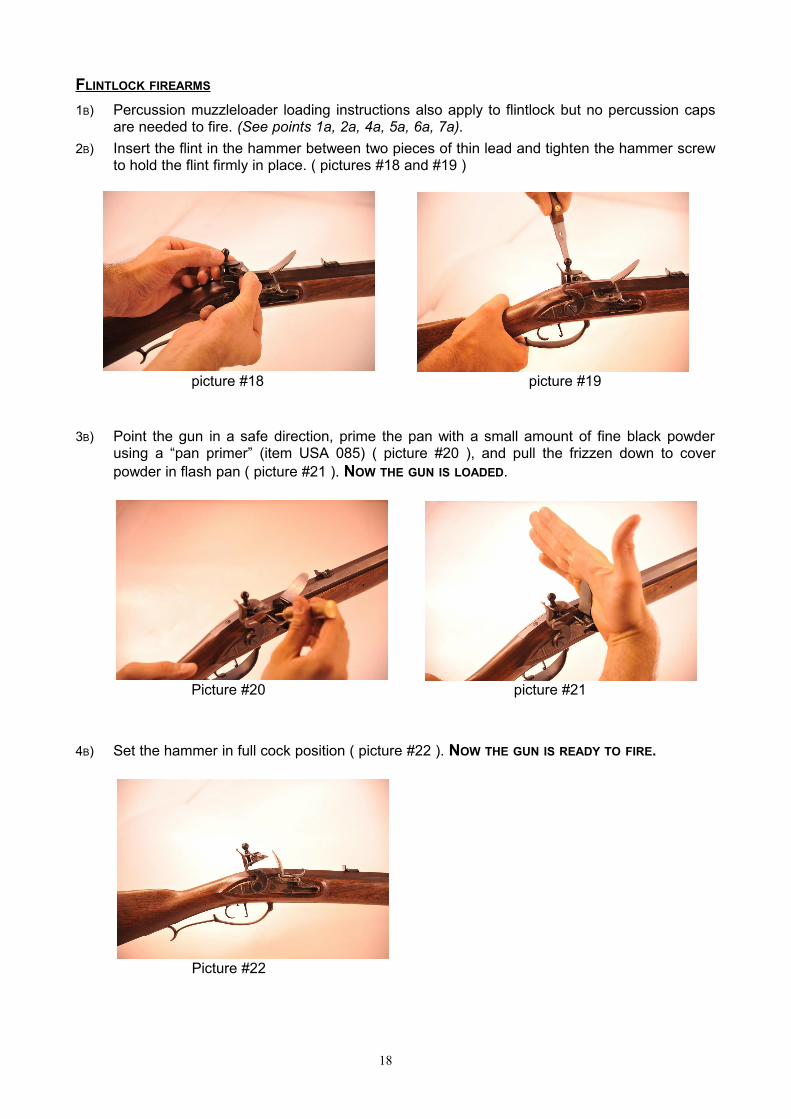
FLINTLOCK FIREARMS
1B) Percussion muzzleloader loading instructions also apply to flintlock but no percussion capsare needed to fire. (See points 1a, 2a, 4a, 5a, 6a, 7a).
2B) Insert the flint in the hammer between two pieces of thin lead and tighten the hammer screwto hold the flint firmly in place. ( pictures #18 and #19 )
picture #18 picture #19
3B) Point the gun in a safe direction, prime the pan with a small amount of fine black powderusing a “pan primer” (item USA 085) ( picture #20 ), and pull the frizzen down to coverpowder in flash pan ( picture #21 ). NOW THE GUN IS LOADED.
Picture #20 picture #21
4B) Set the hammer in full cock position ( picture #22 ). NOW THE GUN IS READY TO FIRE.
Picture #22
18

5B) When the trigger is pulled, the hammer will move forward and down across the face of thefrizzen. The flint edge, striking the frizzen, will produce sparks. The sparks, upon regnitingthe priming, will cause flashes that travelling through the touch hole will ignite the maincharge. ( picture #23 )ATTENTION : both flint and frizzen must be completely dry.
Picture #23
6B) After firing slide the ramrod into the empty bore and wait for one full minute beforeloading the next powder charge; this will allow any remaining sparks in the barrel to burnout.
7B) If a misfire or a failure to fire should occur, keep the muzzle-loader pointed in a safedirection and wait for at least one minute, then reprime and use a nipple pick to force a smallamount of the priming powder charge into the touch hole and then fire again.If after some attempts the gun does not fire, UNLOAD IT, using the proper caliber bullet puller(item USA 545). MAKE SURE THE HAMMER IS IN A SAFETY POSITION.Using a small eye dropper or medicine dropper filled with water, forceably inject the waterinto the breech plug ( picture #24 )
picture #24
. Water will cause the black powder to become inactive. After you have done this 3-5 times,wait at least 30 minutes for the black powder, to become completely saturated with water.
Further screw the bullet puller to the ramrod, insert it into the barrel to catch the bullet; rotating the ramrod will ease the bullet pulling (picture #25) You can now remove the powder.
Picture #25
19

CLEANING INSTRUCTIONSFOR SINGLE SHOT MUZZLE LOADING GUNS
WARNING : BEFORE PROCEEDING ALWAYS MAKE SURE THE FIREARM IS UNLOADED AND
POINTED IN A SAFE DIRECTION.
HOW TO REMOVE THE BARREL FROM STOCK
Our line of muzzleloader is devided in two groups of weapons: the first ones which barrel endswith a breech plug into the stock. The second ones with a hook breech tang and plug.
1c) For the guns of the first group to remove the barrel from the stock, once removed theramrod, you have to unscrew the tang screw and then take the pins and/or the wedge off.
( pictures #26 and #27 )
picture #26 picture #27
2c) For the guns of the seconds group, the barrel is fixed to the stock with wedges. Onceremoved the ramrod, retract the wedge or wedges, handle the barrel at the muzzle androtate towards the height, the lug will disengage from its seat. ( pictures #28 and #29 )
picture #28 picture #29
20

CLEANING
Black powder leaves a lot of fouling in the barrel and it is highly corrosive. After the day’s shooting,an accurate cleaning is recommended.
1d) Percussion rifles or pistols: remove the nipple.Flintlock rifles or pistols: remove the vent.The work can be easier leaving the breech plug barrel into hot water for some minutes.
2d) Scrub bore with hot soapy water or in hot water with specific detergent (item USA 487) andwipe all powder fouling from all other metallic parts too.
3d) Flush the barrel with the hottest clean water available to remove soap.
4d) Dry barrel and all metallic parts rapidly with fresh patches while they are still hot.
5d) Oil the barrel lightly as soon as it cools inside and out. Apply a coat of oil to all metallic partstoo.
6d) Replace the nipple (on percussion models), or vent (on flintlock models).
HOW TO REMOVE THE BREECH PLUG FROM BARREL
1e) Percussion rifles or pistols with drum: remove the nipple and the drum. Before removingthe drum, mark a small position line for the drum and the barrel, such to mount it in the sameposition. When reassembling the drum and the nipple do not apply an excessive strength, oryou may break the parts. Make sure that the male thread perfectly matches with the one ofthe hole.Percussion rifles or pistols without drum: remove the nipple.Flintlock rifles or pistols: remove the vent.
2e) For all firearms indicated at point 1e: before proceding to the removing of breech plug,make sure to have done a “reference mark” between barrel and breech plug, for the rightposition.
3e) With the barrel held in a bench vice (protected grip), unscrew the breech plug, by using anappropriate wrench.
21

LOADING AND SHOOTING INSTRUCTIONS FOR SIDE BY SIDE MUZZLE LOADING SMOOTH BORE SHOTGUNS
Before proceeding, please make sure to CAREFULLY read the warning seen in the section“IMPORTANT CAUTIONS FOR MUZZLE LOADING SHOOTING” in this booklet.
WARNING : BEFORE PROCEEDING ALWAYS MAKE SURE THE FIREARM IS UNLOADED AND
POINTED IN A SAFE DIRECTION.
ASSEMBLING
1f) Do not force barrel into stock.
2f) Hook the barrel breech plug into the tang make sure the barrel fits properly to the tang.Gently lower the barrel into the barrel channel in the stock. DO NOT FORCE the barrel.
3f) The barrel must fit into the stock perfectly, with a minimal amount of tension in order to holdthe wedges in.
4f) Gently insert the wedges RIGHT TO LEFT. ( picture #30 )
picture #30
LOADING
5f) With the gun pointing in a safe direction place caps on the nipples, set the hammers in fullposition and fire. This operation should be repeated two or three times in order to dry out thebase of bores and the nipples. Now you can start loading. ( picture #31 )
picture #31
22

6f) With the hammers placed at a rest position (down) pour down the righthand barrel the pre-weighed powder charge (see loading tables in this booklet). ( Picture #32 )ALWAYS MAKE SURE OF THE BARREL YOU START WITH.
Picture #32
Slap the side of the barrel in front of the lock, this will allow a small quantity of powder to gointo the nipple. ( picture #33 )
picture #33
7f) Place on the muzzle an over powder cork wad (item USA 093) and a wad (item USA 087)and with the ramrod, carefully press it to a firm seat on top of the powder load.Some shooters use instead of the wad a felt wad (item USA 094) and an additional overpowder cork (item USA 093).It is advisable to mark your ramrod at the muzzle in order to have a reference (see point 17of section “IMPORTANT CAUTIONS FOR MUZZLE LOADING SHOOTING” in this booklet).( Pictures #34 and #35 )
picture #34 picture #35
23

8f) Measure and pour the required weight and size of shot down the barrel (see loading tablesin this booklet), by using a shot-bag (item DP 560) and the over shot wad (item USA 086).( picture #36 ) THERE IS NO NEED TO PRESS TOO MUCH . Now mark again your ramrod at themuzzle. This will insure that all future shots are at the right depth.
( picture #36 )
9f) Start now loading the left side barrel.
10f) With one hammer placed on half cock position and the other on a rest position (down),(NEVER PLACE BOTH HAMMERS AT HALF COCK POSITION AT THE SAME TIME), place the firstcap; PLACE JUST ONE CAP AT A TIME, you can place the second one only after having fired thefirst barrel. CAUTION : NEVER RELOAD A FIRED BARREL WITHOUT REMOVING CAP FROM THE OTHER.
11f) It is possible for the recoil of the first shot to jar the second load from the powder charge so,after having fired the first barrel, wait for at least one minute, then check the position of theloading charge of the second barrel with the reference marks done on your ramrod.If it is not at the right depth, press it down until the reference mark will be at the muzzle ofthe barrel. CAUTION: BE SURE THERE IS NO CAP ON THE NIPPLE.
LOADING MISTAKE
If you have accidentally reloaded the same barrel (you will notice this after having checked thereference marks on your ramrod), UNLOAD THE GUN COMPLETELY, by using a patch-puller (itemUSA 555), MAKE SURE YOU HAVE NOT ANY CAP ON THE NIPPLE.
Using a small eye dropper or medicine dropper filled with water, forceably inject the waterinto the breech plug. Water will cause the black powder to become inactive. After you havedone this 3-5 times, wait at least 30 minutes for the black powder, to become completelysaturated with water. ( picture #37)
picture #37
24

Further screw the patch-puller to the ramrod, insert it into the barrel reaching the over shotwad and pull it out. Repeat the same thing for the felt wad. You can now remove the powder.
( picture #38 )
picture #38
SPECIAL NOTES FOR SIDE BY SIDE MUZZLE LOADING FLINT LOCKS
When using the flintlock double barrel shotgun you must pay extra attention duringshooting. Starting with the hypothesis that both barrels are loaded, ready to shoot, when firingthe first barrel, the flame could also ignite the second barrel, setting the shot off. To avoid this risk,we recommend leaving the pan of the second lock unprimed, while firing the first barrel.
Also, ensure that when both hammers are in the half cock position and the frizzens are closed,that all components should be perfectly parallel. Should the flints be in contact with the frizzens,they can consequently be slightly open, which is undesirable. The solution is to knap the flint witha small hammer, of non-ferritic material such as in our Flintlock tool set USA 513. This operationmust be performed with both barrels unloaded and placed in safe position.
WARNING: Use protection for the eyes and ears.ADDITIONAL protection is needed in case of moustaches and beard, preventing burns fromflame sparks and flint chips.
25

CLEANING
12f) Our shotguns have chromed barrel bores, however the same procedures seen at point 2cand at “CLEANING” of section “CLEANING INSTRUCTIONS FOR SINGLE SHOT MUZZLE LOADING GUNS” inthis booklet, are to be followed.
ATTENTION : the breech plug CANNOT BE REMOVED.
DOUBLE BARREL SHOTGUN WITH INTERCHANGEABLE CHOKE TUBES
Your side by side shotgun can be equipped with interchangeable chokes of various sizes. Never change choke tubes on a loaded firearm. Make sure choke tube is properly tightened before shooting. It is wise to check tube
periodically when hunting or shooting for an extended period of time. We do not recommend chokes tighter than improved-cylinder for steel shot.
Choke tubes measurements
Size(mm)
Chokes Pedersolicode CHOKE
10 ga. 12 ga.Variation
In 0,10 mmLines on mouth
of the tube10 ga. 12 ga.
denominations
18,65 17,47 9 ÷ 10 1 line USA 125 USA 120 Extra - Full18,90 17,67 7 ÷ 8 2 lines USA 122 USA 117 Improved - Modified19,20 17,87 4 ÷ 6 3 lines USA 123 USA 118 Modified19,40 18,17 2 ÷ 3 4 lines USA 126 USA 121 Improved - Cylinder19,60 18,37 0 ÷ 1 5 lines USA 124 USA 119 Cylinder
26

LOADING AND SHOOTING INSTRUCTIONS FOR SIDE BY SIDE MUZZLE LOADING RIFLED BARREL GUNS
KODIAK & SAFARI EXPRESS
Before proceeding, please make sure to CAREFULLY read the warning seen in the section“IMPORTANT CAUTIONS FOR MUZZLE LOADING SHOOTING” in this booklet.
WARNING : BEFORE PROCEEDING ALWAYS MAKE SURE THE FIREARM IS UNLOADED AND
POINTED IN A SAFE DIRECTION.
ASSEMBLING
1g) Do not force barrel into stock.
2g) Hook the barrel breech plug into the tang make sure the barrel fits properly into the tang.Gently lower the barrel into the barrel channel in the stock. DO NOT FORCE the barrel.
3g) The barrel must fit into the stock perfectly, with a minimal amount of tension in order to holdthe wedges in.
4g) Gently insert the wedges RIGHT TO LEFT.( picture #39 )
picture #39
LOADING
5g) With the gun pointed in a safe direction place caps on the nipples, set the hammers in fullposition and fire.This operation should be repeated two or three times in order to dry out the base of boresand the nipples. ( picture #40 ) Now you can start loading.
Picture #40
27

6g) With the hammers placed at a rest position (down), pour down the righthand barrel the pre-weighed powder charge. (see loading tables in this booklet). ALWAYS MAKE SURE OF THE
BARREL YOU START WITH. ( picture #41 )
picture #41
Slap the side of the barrel in front of the lock, this will allow a small quantity of powder to go intothe nipple. ( picture #42 )
picture #42
7g) Center a lubricated cloth patch over the muzzle and place the round ball over it (see points6a, 7a of section “LOADING AND SHOOTING INSTRUCTIONS FOR SINGLE SHOT MUZZLE LOADING GUNS”of this booklet)( picture #43 ). To facilitate this operation we suggest the use of a bulletstarter (art. USA 510), that will help the introducing of the ball for the first 15 cm (6”) ( picture#44 ), then you can continue with the ramrod.
Picture #43 picture #44
28

8g) With one hammer placed on half cock position and the other on a rest position (down),NEVER PLACE BOTH HAMMERS AT HALF COCK POSITION AT THE SAME TIME, place the first cap;PLACE JUST ONE CAP AT A TIME, you can place the second one only after having fired the firstbarrel.CAUTION: NEVER RELOAD A FIRED BARREL WITHOUT REMOVING CAPS FROM THE OTHER.
9g) Start now loading the left side barrel.
10g) It is possible for the recoil of the first shot to jar the second load from the powder charge so,after having fired the first barrel, wait for at least one minute, then check the position of theloading charge of the second barrel with the reference marks done on your ramrod. If it isnot at the right depth, press it down until the reference mark is at the muzzle of the barrel.CAUTION : BE SURE THERE IS NO CAP ON THE NIPPLE.
LOADING MISTAKE
11g) If you have accidentally reloaded the same barrel (you will notice this after having checkedthe reference marks on your ramrod), UNLOAD THE GUN COMPLETELY, using the propercaliber bullet puller. MAKE SURE YOU HAVE REMOVED ANY CAP ON THE NIPPLE.Using a small eye dropper or medicine dropper filled with water, forceably inject the waterinto the breech plug. Water will cause the black powder to become inactive. ( picture #45 )
picture #45
After you have done this 3-5 times, wait at least 30 minutes for the black powder, to become completely saturated with water. Further screw the bullet puller to the ramrod, insert it into the barrel to catch the bullet; rotating the ramrod will ease the bullet pulling. ( picture #46 ) You can now remove the powder.
Picture #46
29

CLEANING
12g) See point 2c and “CLEANING” of section “CLEANING INSTRUCTIONS FOR SINGLE SHOT MUZZLE LOADING GUNS” in this booklet.ATTENTION : the breech plug CANNOT BE REMOVED.
SIGHTING
13g) Your Kodiak & Safari Express rifles have been regulated to group at 50 meters within adiameter of about 15 centimeters, using the suggested loads in the chart.The rear sight is adjustable in elevation and windage. The blade front sight isinterchangeable.
For sighting adjustment, see section “GENERAL TECHNICAL INSTRUCTIONS” in this booklet.
SPECIAL NOTES FOR SIDE BY SIDE MUZZLE LOADING FLINT LOCKS
When using the flintlock double barrel shotgun you must pay extra attention duringshooting. Starting with the hypothesis that both barrels are loaded, ready to shoot, when firingthe first barrel, the flame could also ignite the second barrel, setting the shot off. To avoid this risk,we recommend leaving the pan of the second lock unprimed, while firing the first barrel.
Also, ensure that when both hammers are in the half cock position and the frizzens are closed,that all components should be perfectly parallel. Should the flints be in contact with the frizzens,they can consequently be slightly open, which is undesirable. The solution is to knap the flint witha small hammer, of non-ferritic material such as in our Flintlock tool set USA 513. This operationmust be performed with both barrels unloaded and placed in safe position.
WARNING: Use protection for the eyes and ears.
ADDITIONAL protection is needed in case of moustaches and beard, preventing burns fromflame sparks and flint chips.
30

LOADING AND SHOOTING INSTRUCTIONS
Before proceeding, please make sure to CAREFULLY read the warning seen in the section“IMPORTANT CAUTIONS FOR MUZZLE LOADING SHOOTING” in this booklet.
Picture #47
FOR BRISTLEN A MORGES ® RIFLE
1) The Minié bullet .447 (item USA 523) you can make with our bullet mould block (item USA304-447) must be sized into the proper sizing device USA 515-445 (11,30 mm or 11,28 mm /.445 or .444) and greased with soft grease (item USA 488). ( picture #47 )
2) Pour the proper black powder charge into the barrel using a brass long funnel (item USA346).
3) The bullet has to be placed directly on the black powder.
4) Slightly tap the bullet, avoiding compressing powder charge too much.
5) It is necessary to clean the barrel after each round.
FOR GIBBS RIFLE .40 and .45 calibers
.40 CALIBER
1) The Minié bullet .400/316 grs. (item USA 523), you can make with our bullet mould block(item USA 304-400), sized through the sizing device USA 515-400 (10,16 mm or 10,14 mm /.400 or .399) and greased with soft grease (item USA 488).
or The long bullet .400/310 grs. (items USA 526), you can make with our bullet mould block(item USA 318-400), sized through the sizing device USA 514-400 (10,16 mm or 10,14 mm /.400 or .399) and greased with soft grease (item USA 488). ( picture #47 )
2) Pour the proper black powder charge into the barrel using a brass long funnel (item USA346).
3) The bullet has to be placed directly on the black powder.
4) Slightly tap the bullet, avoiding compressing powder charge too much.
5) It is necessary to clean the barrel after each round
31

.45 CALIBER
1) The long bullet .451/535 grs. (items USA 526), you can make with our bullet mould block (item USA 308-451), sized through the sizing device USA 514-450 (11,43 mm or 10,41 mm /.450 or .449) and greased with soft grease (item USA 488). ( picture #47 )
2) Pour the proper black powder charge into the barrel using a brass long funnel (item USA346).
3) The bullet has to be placed directly on the black powder.
4) Slightly tap the bullet, avoiding compressing powder charge too much.
5) It is necessary to clean the barrel after each round
FOR MORTIMER WHITWORTH & TRYON CREEDMOOR RIFLES
1) The long bullet .451/485 grs (item USA 521) you can make with our bullet mould block (itemUSA 318-451) and the Minié bullet .450 (item USA 523) you can make with our bullet mouldblock (item USA 309-450) must be sized into the proper sizing device USA 514-450 (11,43mm or 11,41 mm / .450 or .449) and greased with soft grease (item USA 488). ( picture #47)
2) Pour the proper black powder charge into the barrel using a brass long funnel (item USA346).
3) The bullet has to be placed directly on the black powder.
4) Slightly tap the bullet, avoiding compressing powder charge too much.
5) It is necessary to clean the barrel after each round.
FOR TRYON MATCH RIFLE
1) The Minié bullet .450 (item USA 523) you can make with our bullet mould block (item USA309-450) must be sized into the proper sizing device USA 515-450 (11,43 mm or 11,41 mm /.450 or .449) and greased with soft grease (item USA 488). ( picture #47 )
2) Pour the proper black powder charge into the barrel using a brass long funnel (item USA346).
3) The bullet has to be placed directly on the black powder.
4) Slightly tap the bullet, avoiding compressing powder charge too much.
5) It is necessary to clean the barrel after each round.
FOR WAADTLÄNDER RIFLE
1) The maxi bullet .454/250 grs. (item USA 522) you can make with our bullet mould block(item USA 308-454), must be greased with soft grease (item USA 488). ( picture #47 )
2) Pour the proper black powder charge into the barrel using a brass long funnel (item. USA346).
3) It is recommended to put inside the barrel a carton wad 1 mm thick between the bullet andblack powder, or a felt wad sized to the gun’s caliber (item USA 097).
4) Slightly tap the bullet, avoiding compressing powder charge too much.
5) It is necessary to clean the barrel after each round.
32

LOADING AND SHOOTING INSTRUCTIONS
Before proceeding, please make sure to CAREFULLY read the warning seen in the section“IMPORTANT CAUTIONS FOR MUZZLE LOADING SHOOTING” in this booklet.
FOR 1857 WÜRTTEMBERGISCHEN RIFLE
1) The Minié bullet .547 (item USA 523), you can make with our bullet mould block (item USA302-547), must be sized into the proper sizing device USA 515-547 (13,90 mm or 13,88mm / .547 or .546) and greased with soft grease (item USA 488). ( picture #47 )
2) Pour the proper black powder charge into the barrel using a brass long funnel (item USA346).
3) The bullet has to be placed directly on the black powder.
4) Slightly tap the bullet, avoiding compressing powder charge too much.
5) It is necessary to clean the barrel after each round.
REAR SIGHT ADJUSTMENT
See exploded view at page 2a of this booklet.
To adjust the rear sight in elevation, please follow these instructions to avoid damaging ordestroying the small teeth on the lower part of item n.7. The small teeth get inserted into theadjusting grooves, as evidenced on the left side of the part. # 2.
a) Unscrew the screw (part. # 1), turning to left.b) Move up or down the rear side blade, according to your necessity.c) Fix the screw (part. # 1), turning to right.
Use the item # 8, which is in an aluminum control accessory, as reference to the rear sight,leaning it on the corresponding step.
FOR ZIMMER & SALOON PISTOLS 4,5 mm caliber
THIS GUN IS TO USE ONLY MUSKET CAPS FOUR WINGS ( RWS 1081 TYPE) TO SHOOT THE PELLET. WE STRONGLY RECOMMEND NOT TO USE ANY KIND OF BLACK POWDER, NOR ANY SMOKELESS
POWDER.
1) With the hammer placed at a rest position (down) insert into the barrel a lead pellet of theproper caliber size.
2) With the pistol pointed to a safe direction place the hammer at half cock position and placethe percussion musket cap on the nipple firmly.
3) When ready to shoot, set the hammer in a full cock position.
NOW THE PISTOL IS READY TO SHOOT.
WARNING
It is suggested to wear safety glasses and gloves to be protected by possible caps chips.
BE AWARE : the gun can be quite dangerous if shot without observing the necessary safetyrules, or inside closed areas, where the pellet may rebound striking, causing seriousaccidents.
33

LOADING AND SHOOTING INSTRUCTIONSFOR REVOLVERS
Before proceeding, please make sure to CAREFULLY read the warning seen in the section“IMPORTANT CAUTIONS FOR MUZZLE LOADING SHOOTING” in this booklet.
1) Keep the revolver’s barrel upward, hammer in the safety position (1st. cock) to rotate thecylinder for loading. ( picture #48 ) Prepare the black powder charge, as suggested in thecorresponding chart, using a powder measure (item USA 192). Pour the load into onechamber. ( picture #49 )
picture #48 picture #49
2) Always with the barrel upward, insert an over powder felt wad of the proper caliber size (itemUSA 094), then seat the round ball on top of it at the chamber mouth. ( picture #50 )
picture #50
3) Rotate the cylinder to place the loaded chamber under the loading lever and push it until theball is well seated on the felt wad. The ball must seat slightly under the cylinder chamber rim.Use the same procedure for all the chambers. ( picture #51 )
picture #51
34

4) Put some grease (item USA 488) on each ball and seal all the chambers. This may preventpossible flash back, as well as the simultaneous ignition of the other loads. The grease alsohelps the cleaning. ( picture #52 )
picture #52
5) After having sealed with the grease all the chambers, keep the muzzle lowered and therevolver pointed to a safe position, put the caps onto each nipple; if necessary squeeze themslightly to ensure their snug fit on the nipples. This will avoid to loose the other caps at thefirst shot. ( picture #53 )
picture #53
35

DISASSEMBLING AND ASSEMBLING INSTRUCTIONSFOR CARLETON UNDERHAMMER PISTOL
WARNING : BEFORE PROCEEDING ALWAYS MAKE SURE THE FIREARM IS UNLOADED AND
POINTED IN A SAFE DIRECTION.
See exploded view at page 52 of this booklet.
DISASSEMBLING
Disassemble the grip from the frame and barrel group by unscrewing the two side screws (#21) and the upper one (part. # 22).
Detach the main spring (# 6) by squeezing it where it contacts the hammer (part. # 3)
Disassemble the plate unscrewing the screws (part. # 19 and # 20) paying attention not to loose the sear spring (part. # 5).
Remove the hammer (part. # 3), the sear (part. # 4) and the trigger pin (part. # 16) using a slender alignment punch, then remove the trigger (part. # 14).
Remove the hammer mainspring (part. # 6) by disassembling the mainspring stud (part. # 7) and unscrewing the stud screw (part. # 25).
ASSEMBLING
4) Assemble the trigger (part. # 14) by pulling the adjusting screw (part. # 15) while it is still inserted in the frame, paying attention that the trigger can rotate freely.
5) Put in the sear spring (part. # 5) while keeping it in position with a slender alignment punch inserted from the left side of the gun during the time necessary to assemble all inside parts until you insert the plate screw (part. # 20). The shorter sear spring side has to be placed in the inside of the upper part of the frame, while the lower bent side has to lock in the trigger front. Fit the trigger (part. # 14) inserting the trigger pin (part. # 16). First tighten the shorter plate screws (part. # 19), then the long screw (part. # 20) paying attention to the alignment punch, which has to be removed slowly, while you are tightening the long screw.
6) Assemble the main spring (part. # 6) in the frame back side with the main spring stud (part. # 7) and lock it manually to its seat in the hammer.
Assemble the grip to the frame and barrel group tightening the properscrews (part. # 21 and # 22).
36

DISASSEMBLING AND ASSEMBLING INSTRUCTIONSFOR COOK UNDERHAMMER PISTOL
WARNING : THE COOK UNDERHAMMER PISTOL IS NOT FITTED WITH THE SAFETYFEATURE OF A HALF COCK POSITION. WE RECOMMEND PAYING CLOSE ATTENTIONDURING LOADING AND SHOOTING PROCEDURES.TO LOAD THE GUN, KEEP THE HAMMER IN THE REST POSITION ON THE NIPPLE WITHOUTTHE PRIMING CAP.
it is possible to vary the trigger pull by adjusting the grub screw (#15 onthe exploded view). by tightening or loosening it, the hammer position will move in or out, varying the length of pull. to lock the adjusting grub screw in the set position, thus preventing movement during shooting, we equipped the pistol with a second grub screw (#16 of the exploded view) which intercepts the adjusting grub screw, keeping it fixed. however, for safety purposes we recommend regularly checking the parts to make sure the trigger pull did not vary. to modify the position of the adjusting grub screw, proceed as follows:with the gun unloaded, and the hammer resting on the uncapped nipple, and hands away from the trigger, unlock the main spring, pulling it away from the trigger and rotate it. ( fig.1 – 2 )
1 2
37

unscrew the grub screw #16 ( fig. 3 ). adjust the adjusting grub screw #15 until you set the correct position of the trigger pull. ( fig. 4 )
3 4we reccomend to allow a distance between the hammer and the trigger to ensure an adequate resistence of the hammer to shooting vibrations as well as accidental impacts. you can then fix the set the position by tightening firmly the grub screw #16, to ensure it is intercepting the adjusting grub screw #15. check that the adjusting grub screw is fixed, unable to loosen.
to reposition the main spring, rotate it towards the trigger until it is in contact with the frame, such that by squeezing it, the main spring can be locked in its seat. ( fig. 5 )
5to verify that the trigger pull adjustment is within safety limits, you can make the following test:gun unloaded and uncapped, keeping the muzzle pointed towards a safe direction, put the hammer in the cocked position ready to shoot. holding the gun firmly, finger off the trigger, you can tap the barrel onto a padded surface. the test will help to verify whether the hammer is maintaining the cocked position, thus preventing any accidental discharge. ( fig. 6 – 7 )
6 7
38

disassembly of the barrelyour cook underhammer pistol has the barrel fixed to the frame by a tapered cross pin connecting the two parts ( fig. 8 )
8
to disassemble the barrel, proceed as follows:make sure the gun is unloaded and uncapped.should you have available a work bench with a vise, you can lock the barrel at the octagonal section into apadded vise.alternatively, use a table or a hard surface covered with a cloth. the profile of the gun has an irregular form, therefore we recommend that you find a soft support surface thatwill not damage the stock, which is the fragile part of the assembly, thus avoiding the risk of breakage duringthe disassembly process. ( fig. 9 )
9
39
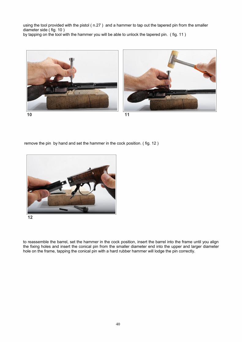
using the tool provided with the pistol ( n.27 ) and a hammer to tap out the tapered pin from the smaller diameter side ( fig. 10 )by tapping on the tool with the hammer you will be able to unlock the tapered pin. ( fig. 11 )
10 11
remove the pin by hand and set the hammer in the cock position. ( fig. 12 )
12
to reassemble the barrel, set the hammer in the cock position, insert the barrel into the frame until you alignthe fixing holes and insert the conical pin from the smaller diameter end into the upper and larger diameterhole on the frame, tapping the conical pin with a hard rubber hammer will lodge the pin correctly.
40

INSTRUCTIONS FOR ASSEMBLINGTHE RIFLE KIT
THESE INSTRUCTIONS SHEETS ARE ONLY A GENERAL GUIDE. PLEASE CHECK THE CORRECT PART NUMBER OF YOUR GUN ON SPECIFIC SPARE PARTS LIST .
Our compliments on your choice! A scrupulous selection of the materials and the accurate workingtechniques make your new gun a product, which is synonymous of prestige and quality.The kit that you are going to finish has been pre-assembled; all the metal parts have fit to thestock and you have only to polish and finish them.If it is not so, you may proceed paying attention to our instructions.Reminding that the most feared enemy of the “do it yourself” is hurried work, we wish you goodluck … enjoy it.These brief notes want to be an explicative guide to enable you to finish work a kit of any kind ofour models.Following you will find some examples featuring various building solutions.
See figures and exploded view at pages 3a, 4a, 5a, 6a, 7a, 8a of this booklet.
1) (See fig.1) - Start by installing the barrel into the barrel channel of the pre-carved stock.Carefully remove any excess wood beneath and around the barrel tang. File the tang downuntil it is flush with the stock wrist. File from metal to wood, not the reverse. This preventschipping or splintering of the wood.
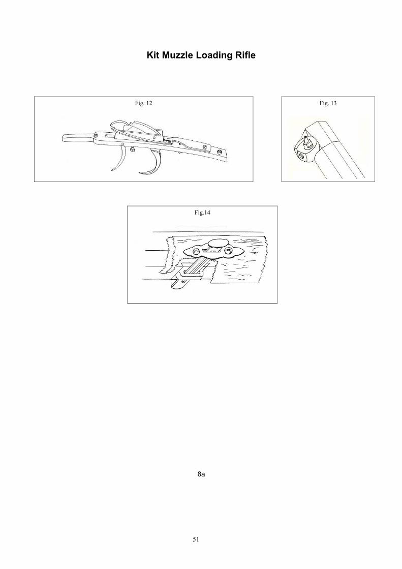
2) INSTALLATION OF TRIGGER (See fig. 4) - With barrel installed in stock (use a clamp or heavyrubber band to keep barrel from falling out), install tang screw (11) through tang and stock.This will line up trigger plate. (part. # 23) As with the tang, install trigger plate flush with stocksurface. Next install trigger (part. # 24), using trigger pin (part. # 25), to trigger plate. Installinto stock, removing the wood as necessary to allow the trigger to move freely. If kit has settriggers (fig. 12), follow the same procedure as with the trigger, fitting one piece at a time.The trigger assembly is held to the stock by the tang screw and a small wood screw at therear of the trigger plate.
3) INSTALLATION OF LOCK AND SIDE PLATE (See figs. 2, 6, 9) - Disassemble lock. Stock is pre-inletted for the lock. The location of the lock is determined by the hammer (part. # 40) to thenipple (part. # 14) / fig. 9, and the sear (part. # 38) to the trigger (part. # 24) / fig. 2. Installlock plate into recess removing only what wood is necessary to make lock surface flush withstock. (In the case of a flintlock, the plate must be fitted tight against and in contact with thebarrel flat). Using fig. 6, install lock mounting screws (part. # 10) through side plate (part. #9), through pre-drilled holes in stock and screw them into the pre-tapped holes in the lockplate. Install side plate (part. # 9) into stock. As with trigger assembly, install lock parts tolock plate and fit to stock one part at a time. Remove wood necessary to allow full and freemovement of parts.
4) FOR FLINTLOCK (See fig. 9a) - Install touch hole liner (part. # 16A) into the pre-threaded holein the side of the barrel. The liner should be flush with the surface of the barrel flat. FOR PERCUSSION (See fig. 9) - Install the drum (part. # 16) into the pre-threaded hole in theside of the barrel. The drum should fit so that nipple (part. # 14) will align with hammer nose(part. # 40a). If it does not, file the drum shoulder a little at a time to obtain the proper fit. GO
SLOWLY SO AS NOT TO STRIP THE THREADS WHEN TIGHTENING THE DRUM TO THE BARREL.
41

5) COMPLETE THE LOCATION OF THE BARREL TO THE STOCK (See fig. 5) - With barrel in stock, fitnose cap (part. # 8) into position. Remove only wood as necessary to have a tight fit.Carefully measure and drill hole for pin (part. # 18). Finish nose cap and stock flush to eachother (Fig. 5a). Remaining barrel pins can now be installed. To find locations for pins (part. #18) and to secure barrel to stock: measure from barrel muzzle to the center of each barrel lug (these are already attached
to the bottom of the barrel); use the top of the barrel to locate the depth for drilling stock through the barrel lugs. Get
measurement from barrel, then re-install barrel into stock. Clamp barrel and stocktogether. Mark spot to drill on stock and DRILL STOCK AND BARREL TOGETHER.
6) INSTALLATION OF THIMBLES (See fig. 7) - Install and drill as with barrel pins.
7) INSTALLATION OF CAP BOX OR PATCH BOX (See fig. 11) - Install into pre-contoured recess onbutt stock. Remove only enough wood to make the metal flush with the wood surface. Installwood screws. Finish flush with stock.
8) INSTALLATION OF SIGHTS (See fig. 8) - Front sight (part. # 13) and rear sight. (part. # 12)Clean up dove tail slots and dove tail on sights. Cut in sights using a three cornered jeweler’sfile removing only enough metal to make a tight fit of the sights into the dovetails.
9) INSTALLATION OF THE RAMROD TIPS (See fig. 10) - Parts # 3 and # 30. Install as shown.Clamp in place and drill. Use a countersink drill to enlarge the mouth of the holes you havedrilled. This will allow you to peen the ends of the pins to make a tight fit. Finish flush withramrod diameter.
10) INSTALLATION OF TRIGGER GUARD - To find location, install front screw through pre-drilledhole in trigger guard and screw into pre-threaded hole in trigger plate (see fig. 2, d). This willlocate the correct position. Install wood screw through pre-drilled hole in rear of trigger guard(part. # 5) and into stock.
11) WOOD FINISHING - Remove trigger guard (part. # 5), trigger (part. # 24), lock (part. # 39) andthimbles (part. # 22). Thimble (part. # 21) should be left installed as it will be flush with thefinished stock. Use a smooth file to bring the stock and metal parts down to each other.These file marks must be removed by using consecutively finer and finer grades ofsandpaper. Care should be taken around the lock recess. DO NOT REMOVE TOO MUCH WOOD
HERE. By sanding in this manner, it will assure that metal and wood surfaces are flush. Themetal parts can now be taken off the stock. Stain can be applied. Additional coats of staincan be added to darken the stock to the desired shade. LET EACH COAT DRY BETWEEN
APPLICATIONS. This may raise the grain of the wood making it feel rough to the touch. If thisoccurs, rub with 4/0 steel wool dipped in a little stain. LET DRY. The sealer can now beapplied. Follow the manufacturer’s directions. LET DRY COMPLETELY BETWEEN APPLICATIONS.The brass parts can be polished with emery paper and polished or buffed. Finishing of steelparts, barrel and screws. Barrel flats which can be seen should be draw filed and polishedwith consecutively finer and finer emery paper. Follow same procedure with heads of steelscrews. For cold bluing or rust, follow manufacturer’s instructions. For best blue or rustfinish, wash all surfaces with a degreaser after polishing and DO NOT HANDLE AGAIN WITH
BARE HANDS UNTIL PROCESS IS COMPLETED.
Re-assemble rifle. KIT IS NOW COMPLETE.
If you chose another kit gun of our models, some of the features may be different from those listedin these assembling instructions.Even if there is a different shaped patch box (drawing 11) a trigger guard with set trigger (drawing12), a forged drum into the barrel, instead of a screwed one (drawing 13) a different barrel tostock fitting (drawing 14) or other variations, these will not prevent you from finishing the kit gun.
42

INSTRUCTION FOR ASSEMBLINGTHE PISTOL KIT
THESE INSTRUCTIONS SHEETS ARE ONLY A GENERAL GUIDE. PLEASE CHECK THE CORRECT PART NUMBER OF YOUR GUN ON SPECIFIC SPARE PARTS LIST .
See figures and exploded view at pages 9a, 10a, 11a, 12a of this booklet.
1) (See fig. 1) - Start by installing the barrel into the barrel channel of the pre-carved stock.Carefully remove any excess wood beneath and around the barrel tang. File the tang downuntil it is flush with stock wrist. File from metal to wood, not the reverse. This preventschipping or splintering of the wood.
2) INSTALLATION OF TRIGGER (See fig. 4) - With barrel installed in stock (use a clamp or heavyrubber band to keep barrel from falling out), install tang screw (part. # 3) through tang andstock. This will line up trigger plate. As before, with the tang, install trigger plate (part. # 13)flush with stock. Next install trigger (part. # 14) using trigger pin (part. # 12) to trigger plate.Install the assembly into stock removing wood as necessary to allow the trigger to movefreely. If the kit has set triggers, follow the same procedure as with the first trigger fitting onepiece at a time. The trigger assembly is held to the stock by the tang screw (part. # 3) and asmall wood screw at the rear of the trigger plate.
3) INSTALLATION OF LOCK AND SIDE PLATES (See figs. 2, 6, 9) - Disassemble lock. The stock ispre-inletted for the lock. The location of the lock is determined by the hammer (part. # 36A)to the nipple (part. # 40) / fig. 9, and the sear (part. # 27) to the trigger (part. # 14) / fig. 2.Install lock plate into recess removing only what wood is necessary to install into stock. (Incase of a flintlock, plate must fit tight against the barrel). Install lock mounting screw (part. # 1) through pre-drilled holes in stock (fig. 6). Screw intopre-tapped holes in lock plate. Install side plate (part. # 2) into the stock flush with woodsurface. As with trigger assembly, install lock parts to lock plate and fit to lock recess onepart at a time. Remove wood as necessary to allow full free movement of all internal parts.
4) FOR FLINTLOCK: install touch hole liner (part. # 7) into pre-threaded hole in side of barrel (seefig. 9a). Liner should be flush with barrel flat.FOR PERCUSSION: install drum (part. # 7A) into pre-threaded hole in side of barrel (fig. 9).Drum should fit so that nipple (part. # 40) will align with hammer nose (part. # 36A). If not,file drum shoulder a little at a time to adjust the fit. Go slowly so as not to strip the threadswhen tightening.
5) COMPLETE THE LOCATION OF BARREL TO STOCK (See fig. 5) - With barrel in stock, fit nose cap(part. # 9) into position. Remove only wood as necessary to have a tight fit. Finish nose capand stock flush to each other.Barrel pins can now be installed (fig. 7). To find location for pin (part. # 11) to hold barrel tostock: Measure from barrel muzzle to center of each barrel lug (the lugs are already attached to thebottom of the barrel).Use the top of the barrel to locate the depth for drilling through stock and barrel lug. Getmeasurement from barrel, then re-install barrel into stock and clamp barrel and stocktogether. Mark spot to drill on stock and DRILL STOCK AND BARREL TOGETHER.
6) INSTALLATION OF THIMBLES (See fig. 7) - Install and drill holes in same manner as with barrelpins.
7) INSTALLATION OF SIGHTS (See fig. 8) - Front sight (part. # 5), and rear sight (part. # 6). Cleanup dovetail slots and check fit of sights to dovetail. Use a three-cornered jeweler’s file toremove what metal necessasry to make a tight fit.
43

8) INSTALLATION OF TRIGGER GUARD - To find proper location, install front screw (part. # 16)through pre-drilled hole in trigger guard and screw into pre-tapped hole in trigger plate. Thiswill properly locate it. Install wood screw (part. # 17) throught pre-drilled hole in rear oftrigger guard (part. # 15) and into stock.
9) WOOD FINISHING - Remove trigger guard (part. # 15), trigger (part. # 14), lock (part. # 29A)and thimble (part. # 39).Thimble (part. # 38) should be left installed as it will be flush with the finished stock. Use asmooth file to bring stock and metal parts down to each other. These file marks must beremoved by using consecutively finer and finer grades of sandpaper. Care should be takenaround the lock recess. DO NOT SAND TOO MUCH WOOD OFF. By doing the sanding in thismanner, it will assure that metal and wood surfaces are flush.The metal parts can now be taken off the stock. Stain can be applied. Additional coats ofstain can be applied to darken the stock to the desired shade. LET STAIN DRY BETWEEN
APPLICATIONS. This may raise the grain of the wood making it feel rough. If grain is raised,rub with 4/0 steel wool dipped in a little stain. LET DRY.The sealer can now be applied. Follow the manufacturer’s instructions. LET DRY COMPLETELY
BETWEEN APPLICATIONS.The brass parts can be polished with emery paper and polished or buffed.Finishing of steel parts-barrel and screws. Barrel flats which can be seen should be drawfiled and polished with consecutively finer and finer emery paper. Follow same procedurewith heads of screws. For cold bluing or rust, follow manufacturer’s intructions. For best blue or rust finish, after polishing, wash all surfaces with a degreaser and DON’THANDLE WITH BARE HANDS UNTIL PROCESS IS COMPLETE.
Re-assemble pistol. KIT IS NOW COMPLETE.
Following these instructions and the exploded view drawing, you will be able to custom finish yourkit and have YOUR NEW MUZZLE LOADING GUN!
44

1857 Württembergischen rear sight
45
4
5
6
3
2
71
8

2a
Muzzle Loading Rifle
3a
46

NO. NOMENCLATURA LIST LISTE1 Canna Barrel Canon
2 Calcio Stock Monture
3 Bacchetta Ramrod with tips Baguette complète
4 Tabacchiera Patch-box Patch-box
5 Guardamano Trigger guard Pontet
6 Calciolo Butt plate Plaque de couche
7 Piastrina calciolo Toe plate Platine de plaque de couche
8 Fascetta canna Forend cap Bande du canon
9 Fregio Side plate Contre-platine
10 Vite fregio/cartella Lock plate screw Vis de platine
11 Vite codetta/sottoguardia Breech plug screw Vis de queue de culasse
12 Tacca di mira Rear sight Cran de mire
13 Mirino Front sight Guidon
14 Luminello Nipple Cheminée
15 Parafiamma Fire screen Pare-feu
16 Portaluminello Drum Porte-cheminée
16A Focone Vent screw Lumière
17 Copiglia posteriore fissaggio canna Rear barrel pin Goupille postérieure fixation canon
18 Copiglia ant. e inter. fissaggio canna Middle and front barrel pin Goupille interm. et ant. fixation canon
18A Copiglia fissaggio ghiera Thimble pin Goupille pour busette
19 Vite piastrina calciolo Toe plate screw Vis platine de plaque
20 Vite calciolo Butt plate screw Vis de plaque de couche
21 Ghiera posteriore Rear thimble Busette postérieure
22 Ghiera intermedia e anteriore Middle and front thimble Busette intermédiaire et antérieure
23 Sottoguardia Trigger plate Sous-garde
24 Grilletto Trigger Détente
25 Copiglia grilletto Trigger pin Goupille de détente
26 Vite posteriore guardamano Rear trigger guard screw Vis postérieur du pontet
27 Vite anteriore guardamano Front trigger guard screw Vis antérieure du pontet
28 Vite tabacchiera Patch-box screw Vis de patch-box
29 Puntale posteriore bacchetta Rear ramrod tip Embout postérieur baguette
30 Puntale anteriore bacchetta Front ramrod tip Refouloir
31 Vite braghetta Bridle screw Vis de bride
32 Vite leva scatto Sear screw Vis de gâchette
33 Braghetta Bridle Bride
34 Molla cane Mainspring Grand ressort
35 Noce con tirantino Tumbler Noix
36 Vite molla leva scatto Sear spring screw Vis du ressort de gâchette
37 Molla leva scatto Sear spring Ressort de gâchette
38 Leva scatto Sear Gâchette
39 Cartella a percussione Percussion lock plate Platine à percussion
39A Cartella a pietra focaia Flintlock plate Platine à silex
40 Cane a percussione Percussion hammer Chien à percussion
40A Cane a pietra focaia Flintlock hammer Chien à silex
41 Vite cane Hammer screw Vis du chien
42 Premipietra Top jaw Mâchoire supérieure
43 Vite premipietra Top jaw screw Vis des mâchoires
44 Martellina o chiusino Frizzen Batterie
45 Molla martellina Frizzen spring Ressort de batterie
46 Vite molla martellina Frizzen spring screw Vis du ressort de batterie
47 Vite martellina Frizzen screw Vis de batterie
4a
47

Kit Muzzle Loading Rifle
Kit Muzzle Loading Rifle
48
Fig. 1
Fig. 3 Fig. 4
Fig. 5 Fig. 5a
Fig. 2

6a
49
Fig. 6
Fig. 7
Fig. 8

Kit Muzzle Loading Rifle
7a
50
Fig. 9 FIG. 9A
Fig. 10Fig.11
Kit Muzzle Loading Rifle
8a
51
Fig.14
Fig. 12 Fig. 13

Muzzle Loading Pistol
9a
52

NO. NOMENCLATURA LIST LISTE
1 Vite fregio/cartella Lock plate screw Vis de platine
2 Fregio Side plate Contre-platine
3 Vite codetta/sottoguardia Breech plug screw Vis de queue de culasse
4 Canna Barrel Canon
5 Mirino Front sight Guidon
6 Tacca di mira Rear sight Cran de mire
7 Focone Vent screw Lumière
7A Portaluminello Drum Porte-cheminée
8 Calcio Stock Monture
9 Fascetta canna Forend cap Bande du canon
10 Vite fascetta canna Forend cap screw Vis de bande du canon
11 Copiglia fissaggio ghiera Thimble pin Goupille pour busette
12 Copiglia grilletto Trigger pin Goupille de détente
13 Sottoguardia Trigger plate Sous-garde
14 Grilletto Trigger Détente
15 Guardamano Trigger guard Pontet
16 Vite anteriore guardamano Front trigger guard screw Vis antérieure du pontet
17 Vite posteriore guardamano Rear trigger guard screw Vis postérieur du pontet
18 Puntale posteriore bacchetta Rear ramrod tip Embout postérieur baguette
19 Bacchetta Ramrod with tips Baguette complète
20 Puntale anteriore bacchetta Front ramrod tip Refouloir
21 Vite molla leva scatto Sear spring screw Vis du ressort de gâchette
22 Vite leva scatto Sear screw Vis de gâchette
23 Molla leva scatto Sear spring Ressort de gâchette
24 Molla cane Mainspring Grand ressort
25 Vite braghetta Bridle screw Vis de bride
26 Braghetta Bridle Bride
27 Leva scatto Sear Gâchette
28 Noce con tirantino Tumbler Noix
29 Cartella a pietra focaia Flintlock plate Platine à silex
29A Cartella a percussione Percussion lock plate Platine à percussion
30 Molla martellina Frizzen spring Ressort de batterie
31 Vite molla martellina Frizzen spring screw Vis du ressort de batterie
32 Martellina o chiusino Frizzen Batterie
33 Vite martellina Frizzen screw Vis de batterie
34 Vite premipietra Top jaw screw Vis des mâchoires
35 Premipietra Top jaw Mâchoire supérieure
36 Cane a pietra focaia Flintlock hammer Chien à silex
36A Cane a percussione Percussion hammer Chien à percussion
37 Vite cane Hammer screw Vis du chien
38 Ghiera posteriore Rear thimble Busette postérieure
39 Ghiera anteriore Front thimble Busette antérieure
40 Luminello Nipple Cheminée
10a
53

Kit Muzzle Loading Pistol
11a
54
Fig. 4
Fig. 5
Fig. 1 Fig. 2
Fig.3
Fig. 6

Kit Muzzle Loading Pistol
12a
55
Fig. 7
Fig. 8
Fig. 9

'Carleton' Underhammer Custom
56

Nomenclatura / List / Liste
No.Italiano English Français1 Bascula Frame Carcasse2 Cartella Frame lid Platine3 Cane Hammer Chien4 Leva scatto Sear Gâchette5 Molla recupero leva Sear spring Ressort de gâchette6 Molla cane Mainspring Ressort du chien7 Zocchetto molla cane Mainspring stud Plaque ressort du chien8 Canna Barrel Canon9 Mirino a perla Pearl sight Guidon à perle10 Porta luminello Drum Porte-cheminée11 Tacca di mira Rear sight Cran de mire12 Calcio grezzo Stock not finished Poignée semi-ouvré12aCalcio finito Stock finished Poignée ouvragé13 Rondella laterale Stock washer Rondelle latérale14 Grilletto Trigger Détente 15 Vite regolazione scatto Sear adjusting screw Vis de réglage détente16 Copiglia grilletto Trigger pin Goupille détente17 Copiglia leva scatto Sear pin Goupille de gâchette18 Luminello Nipple Cheminée19 Vite corta cartella Short frame lid screw Vis courte de platine20 Vite lunga cartella Long frame lid screw Vis longue de platine21 Vite laterale calcio Side stock screw Vis latérale de poignée22 Vite superiore calcio Upper stock screw Vis supérieure de poignée23 Vite fissaggio tacca di mira Rear sight screw Vis de blocage cran de mire24 Vite regolazione tacca di mira Rear sight adjusting screw Vis de réglage cran de mire25 Vite zocchetto molla cane Mainspring stud screw Vis de plaque ressort du chien26 Perla per mirino Sight's pearl Perle pour le guidon
57