General Formulation of Space Frame Element Stiffness ...esrcen.com/Paper-HASTAG-2015-TAPFRM.pdf ·...
14
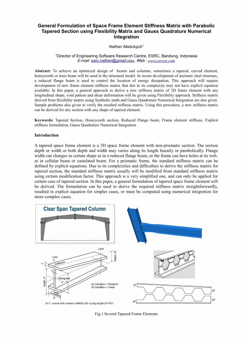
General Formulation of Space Frame Element Stiffness Matrix with Parabolic Tapered Section using Flexibility Matrix and Gauss Quadrature Numerical Integration Nathan Madutujuh 1 1 Director of Engineering Software Research Centre, ESRC, Bandung, Indonesia E-mail: esrc. nathan @ gmai l .co m , Web : www.esrcen.com Abstract: To achieve an optimized design of beams and columns, sometimes a tapered, curved element, honeycomb or truss beam will be used in the structural model. In recent development of aseismic steel structure, a reduced flange beam is used to control the location of energy dissipation. This approach will require development of new frame element stiffness matrix that due to its complexity may not have explicit equation available. In this paper, a general approach to derive a new stiffness matrix of 3D frame element with any longitudinal shape, void pattern and shear deformation will be given using Flexibility approach. Stiffness matrix derived from flexibility matrix using Symbolic math and Gauss Quadrature Numerical Integration are also given. Sample problems also given to verify the resulted stiffness matrix. Using this procedure, a new stiffness matrix can be derived for any section with any shape of tapered element. Keywords: Tapered Section, Honeycomb section, Reduced Flange beam, Frame element stiffness, Explicit stiffness formulation, Gauss Quadrature Numerical Integration Introduction A tapered space frame element is a 3D space frame element with non-prismatic section. The section depth or width or both depth and width may varies along its length linearly or parabolically. Flange width can changes in certain shape as in a reduced flange beam, or the frame can have holes at its web, as in cellular beam or castelated beam. For a prismatic frame, the standard stiffness matrix can be defined by explicit equations. Due to its complexities and difficulties to derive the stiffness matrix for tapered section, the standard stiffness matrix usually will be modified from standard stiffness matrix using certain modification factor. This approach is a very simplified one, and can only be applied for certain case of tapered section. In this paper, a general formulation of tapered space frame element will be derived. The formulation can be used to derive the required stiffness matrix straightforwardly, resulted in explicit equation for simpler cases, or must be computed using numerical integration for more complex cases. Fig.1 Several Tapered Frame Elements
Transcript of General Formulation of Space Frame Element Stiffness ...esrcen.com/Paper-HASTAG-2015-TAPFRM.pdf ·...
General Formulation of Space Frame Element Stiffness Matrix with ParabolicTapered Section using Flexibility Matrix and Gauss Quadrature Numerical
Integration
Nathan Madutujuh1
1Director of Engineering Software Research Centre, ESRC, Bandung, IndonesiaE-mail: esrc. nathan @ gmai l .co m, Web : www.esrcen.com
Abstract: To achieve an optimized design of beams and columns, sometimes a tapered, curved element,honeycomb or truss beam will be used in the structural model. In recent development of aseismic steel structure,a reduced flange beam is used to control the location of energy dissipation. This approach will requiredevelopment of new frame element stiffness matrix that due to its complexity may not have explicit equationavailable. In this paper, a general approach to derive a new stiffness matrix of 3D frame element with anylongitudinal shape, void pattern and shear deformation will be given using Flexibility approach. Stiffness matrixderived from flexibility matrix using Symbolic math and Gauss Quadrature Numerical Integration are also given.Sample problems also given to verify the resulted stiffness matrix. Using this procedure, a new stiffness matrixcan be derived for any section with any shape of tapered element.
Keywords: Tapered Section, Honeycomb section, Reduced Flange beam, Frame element stiffness, Explicitstiffness formulation, Gauss Quadrature Numerical Integration
Introduction
A tapered space frame element is a 3D space frame element with non-prismatic section. The sectiondepth or width or both depth and width may varies along its length linearly or parabolically. Flangewidth can changes in certain shape as in a reduced flange beam, or the frame can have holes at its web,as in cellular beam or castelated beam. For a prismatic frame, the standard stiffness matrix can bedefined by explicit equations. Due to its complexities and difficulties to derive the stiffness matrix fortapered section, the standard stiffness matrix usually will be modified from standard stiffness matrixusing certain modification factor. This approach is a very simplified one, and can only be applied forcertain case of tapered section. In this paper, a general formulation of tapered space frame element willbe derived. The formulation can be used to derive the required stiffness matrix straightforwardly,resulted in explicit equation for simpler cases, or must be computed using numerical integration formore complex cases.
Fig.1 Several Tapered Frame Elements
Basics of The Flexibility Method (Force Method)
The Flexibility Method is a generalization of the Maxwell-Mohr method developed in 1864. In thisapproach, we will release the right node of a fixed end frame element, and apply a unit load in certaindirection, and find the displacement in certain direction. The resulted displacement is the flexibilityterms that can be used to build the flexibility matrix. The flexibility matrix then can be used to derivedthe required stiffness matrix using transformation matrix. Although the flexibility method is notsuitable for computerized solution, it can be used to derived the flexibility terms easily even forcomplex sections, because the displacements can be computed using virtual energy approach, usingthe principle that external work must be equal to internal work. The internal work can be computedusing integration of axial, bending, and shear stress and strain along the length of the member.
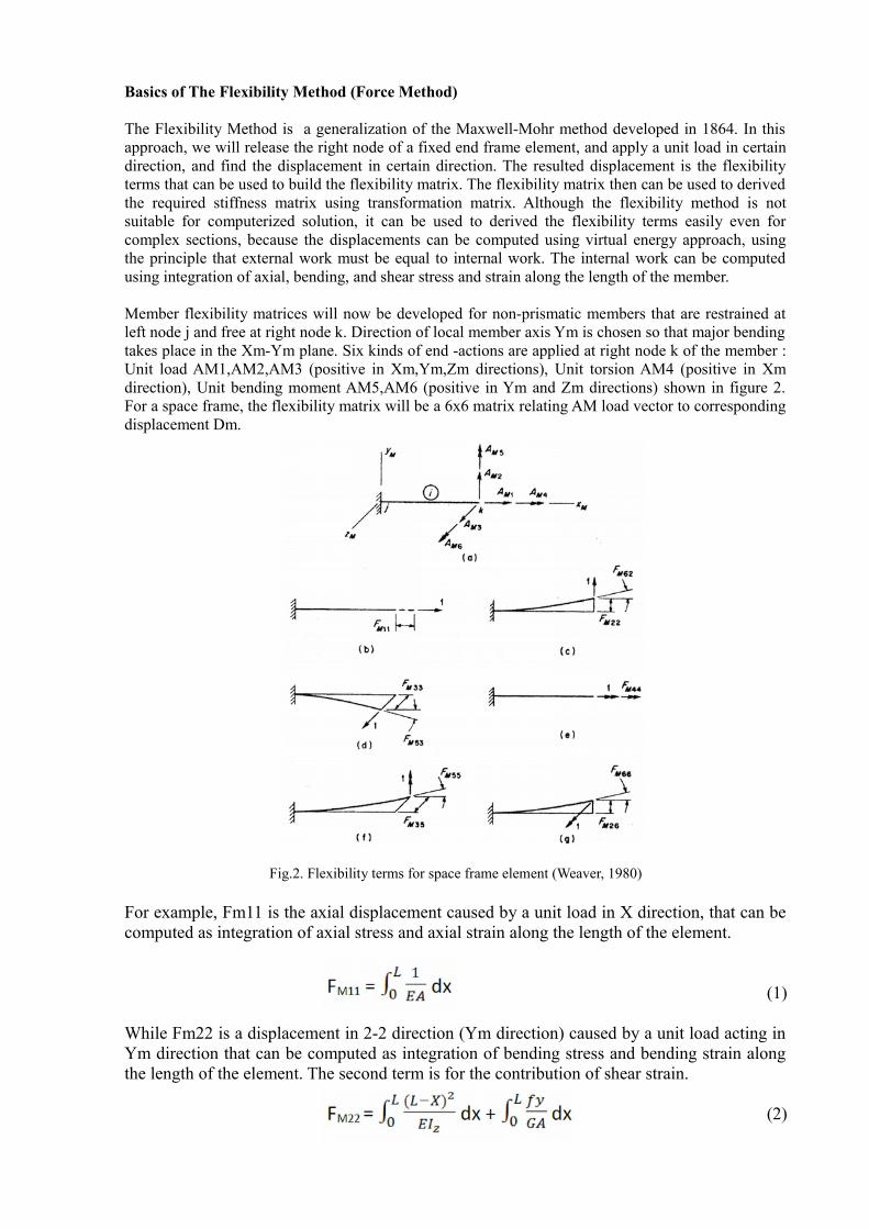
Member flexibility matrices will now be developed for non-prismatic members that are restrained atleft node j and free at right node k. Direction of local member axis Ym is chosen so that major bendingtakes place in the Xm-Ym plane. Six kinds of end -actions are applied at right node k of the member :Unit load AM1,AM2,AM3 (positive in Xm,Ym,Zm directions), Unit torsion AM4 (positive in Xmdirection), Unit bending moment AM5,AM6 (positive in Ym and Zm directions) shown in figure 2.For a space frame, the flexibility matrix will be a 6x6 matrix relating AM load vector to correspondingdisplacement Dm.
Fig.2. Flexibility terms for space frame element (Weaver, 1980)
For example, Fm11 is the axial displacement caused by a unit load in X direction, that can becomputed as integration of axial stress and axial strain along the length of the element.
(1)
While Fm22 is a displacement in 2-2 direction (Ym direction) caused by a unit load acting inYm direction that can be computed as integration of bending stress and bending strain alongthe length of the element. The second term is for the contribution of shear strain.
(2)
Using the same approach, the complete Flexibility terms will be :
(3)
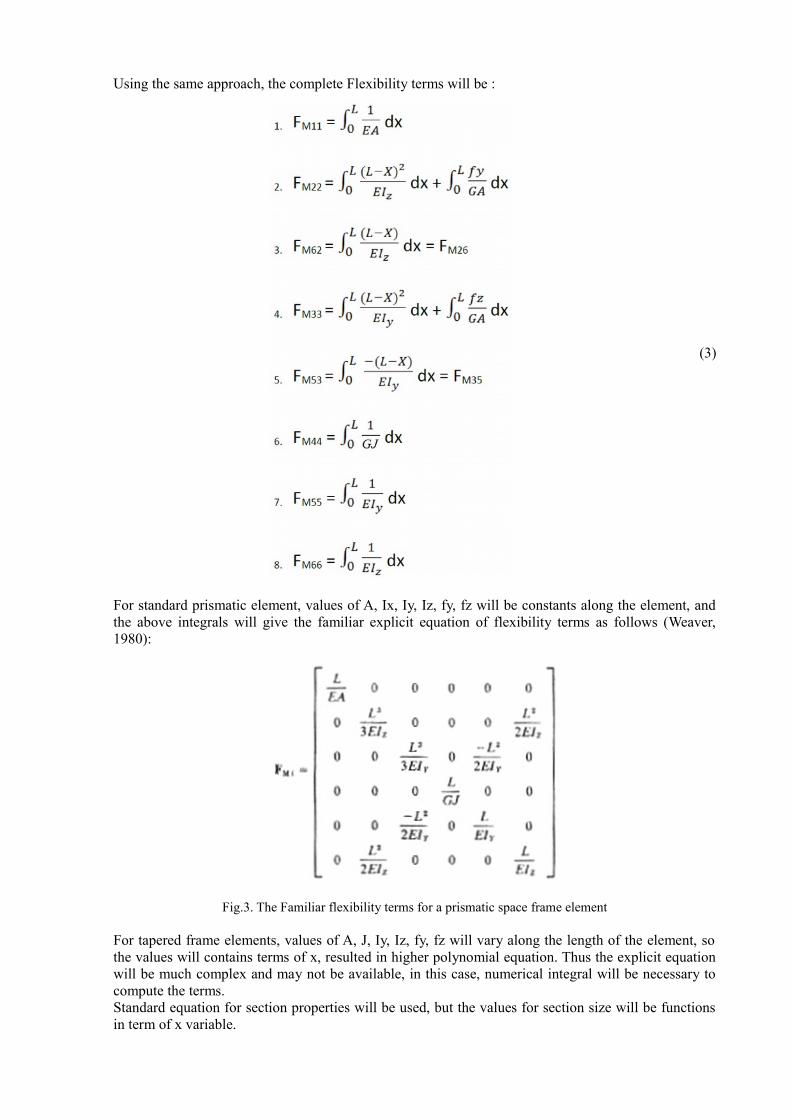
For standard prismatic element, values of A, Ix, Iy, Iz, fy, fz will be constants along the element, andthe above integrals will give the familiar explicit equation of flexibility terms as follows (Weaver,1980):
Fig.3. The Familiar flexibility terms for a prismatic space frame element
For tapered frame elements, values of A, J, Iy, Iz, fy, fz will vary along the length of the element, sothe values will contains terms of x, resulted in higher polynomial equation. Thus the explicit equationwill be much complex and may not be available, in this case, numerical integral will be necessary tocompute the terms. Standard equation for section properties will be used, but the values for section size will be functionsin term of x variable.
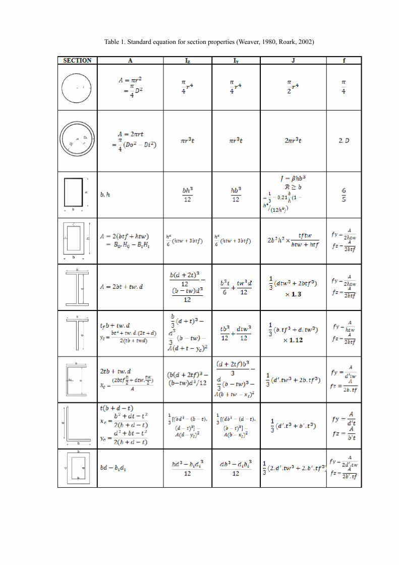
Table 1. Standard equation for section properties (Weaver, 1980, Roark, 2002)
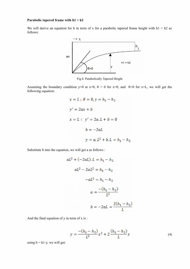
Parabolic tapered frame with h1 > h2
We will derive an equation for h in term of x for a parabolic tapered frame height with h1 > h2 asfollows:
Fig.4. Parabolically Tapered Height
Assuming the boundary condition y=0 at x=0, q > 0 for x=0, and q=0 for x=L, we will get thefollowing equation:
Substitute b into the equation, we will get a as follows :
And the final equation of y in term of x is :
(4)
using h = h1-y, we will get:
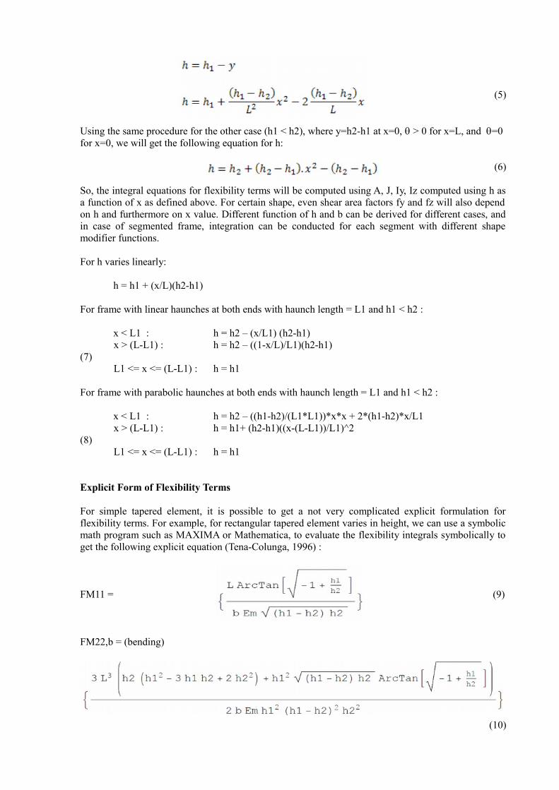
(5)
Using the same procedure for the other case (h1 < h2), where y=h2-h1 at x=0, q > 0 for x=L, and q=0 for x=0, we will get the following equation for h:
(6)
So, the integral equations for flexibility terms will be computed using A, J, Iy, Iz computed using h asa function of x as defined above. For certain shape, even shear area factors fy and fz will also dependon h and furthermore on x value. Different function of h and b can be derived for different cases, andin case of segmented frame, integration can be conducted for each segment with different shapemodifier functions.
For h varies linearly:
h = h1 + (x/L)(h2-h1)
For frame with linear haunches at both ends with haunch length = L1 and h1 < h2 :
x < L1 : h = h2 – (x/L1) (h2-h1) x > (L-L1) : h = h2 – ((1-x/L)/L1)(h2-h1)(7) L1 <= x <= (L-L1) : h = h1
For frame with parabolic haunches at both ends with haunch length = L1 and h1 < h2 :
x < L1 : h = h2 – ((h1-h2)/(L1*L1))*x*x + 2*(h1-h2)*x/L1 x > (L-L1) : h = h1+ (h2-h1)((x-(L-L1))/L1)^2(8) L1 <= x <= (L-L1) : h = h1
Explicit Form of Flexibility Terms
For simple tapered element, it is possible to get a not very complicated explicit formulation forflexibility terms. For example, for rectangular tapered element varies in height, we can use a symbolicmath program such as MAXIMA or Mathematica, to evaluate the flexibility integrals symbolically toget the following explicit equation (Tena-Colunga, 1996) :
FM11 = (9)
FM22,b = (bending)
(10)
FM22,s = (shear)
(11)
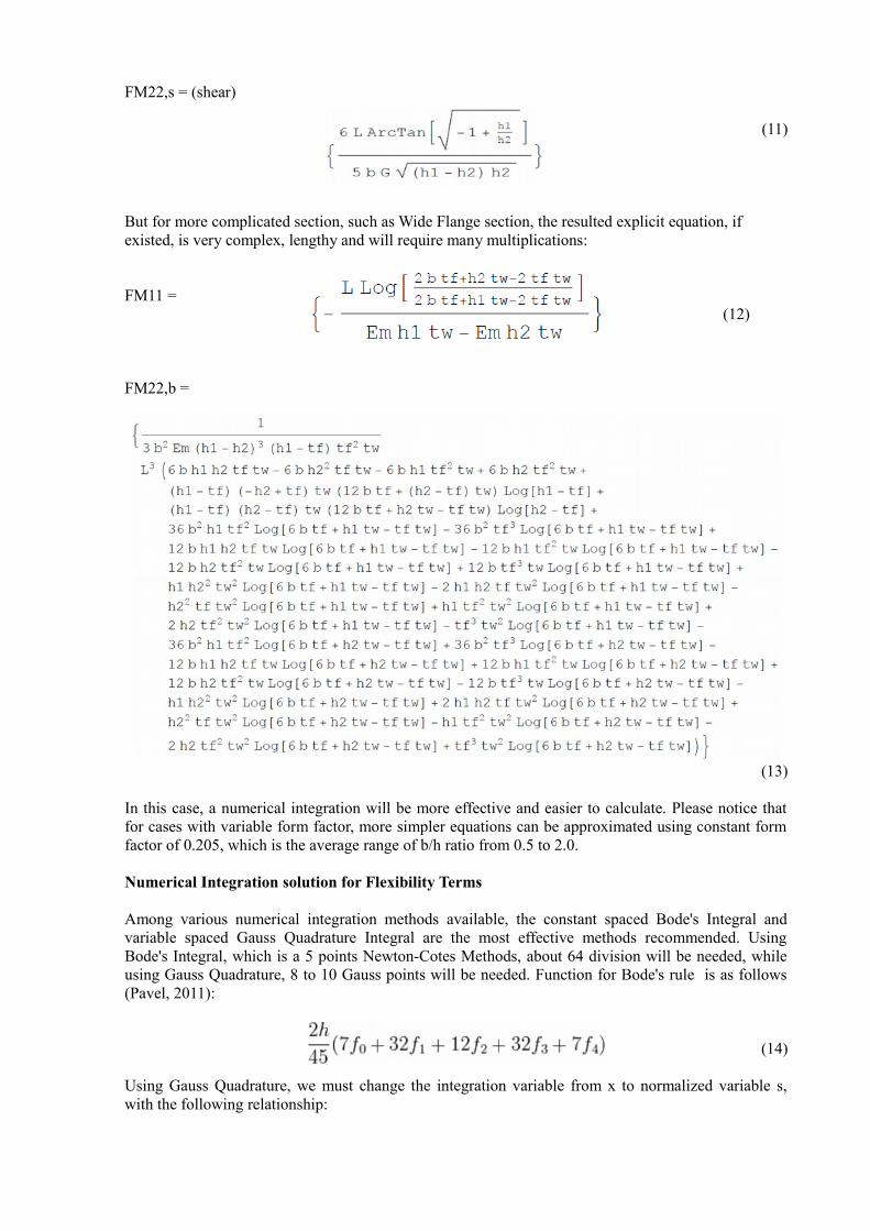
But for more complicated section, such as Wide Flange section, the resulted explicit equation, if existed, is very complex, lengthy and will require many multiplications:
FM11 = (12)
FM22,b =
(13)
In this case, a numerical integration will be more effective and easier to calculate. Please notice thatfor cases with variable form factor, more simpler equations can be approximated using constant formfactor of 0.205, which is the average range of b/h ratio from 0.5 to 2.0.
Numerical Integration solution for Flexibility Terms
Among various numerical integration methods available, the constant spaced Bode's Integral andvariable spaced Gauss Quadrature Integral are the most effective methods recommended. UsingBode's Integral, which is a 5 points Newton-Cotes Methods, about 64 division will be needed, whileusing Gauss Quadrature, 8 to 10 Gauss points will be needed. Function for Bode's rule is as follows(Pavel, 2011):
(14)
Using Gauss Quadrature, we must change the integration variable from x to normalized variable s,with the following relationship:
x = (L/2) (1+s) (15)and dx = (L/2) ds (16)
The integral equation then will be executed as summation of function values evaluated at Gauss points:
(17)
Using standard Gauss Quadrature procedure with boundary from -1 to +1, we must transform the function and differential form f(x) to f(s) and from dx to ds using equation (15) and (16).
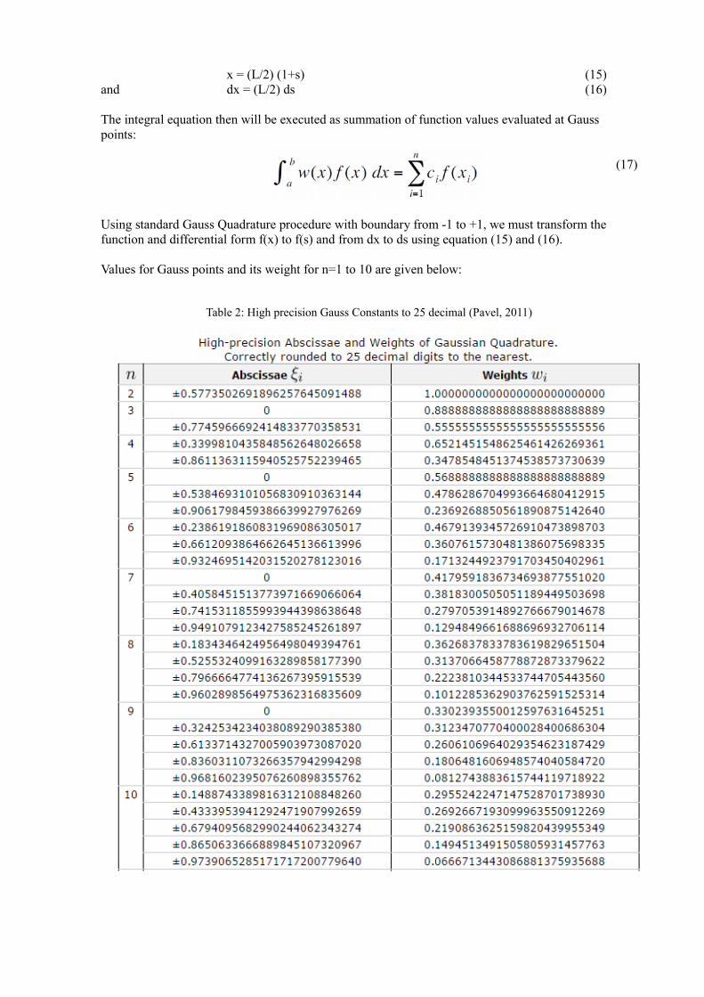
Values for Gauss points and its weight for n=1 to 10 are given below:
Table 2: High precision Gauss Constants to 25 decimal (Pavel, 2011)
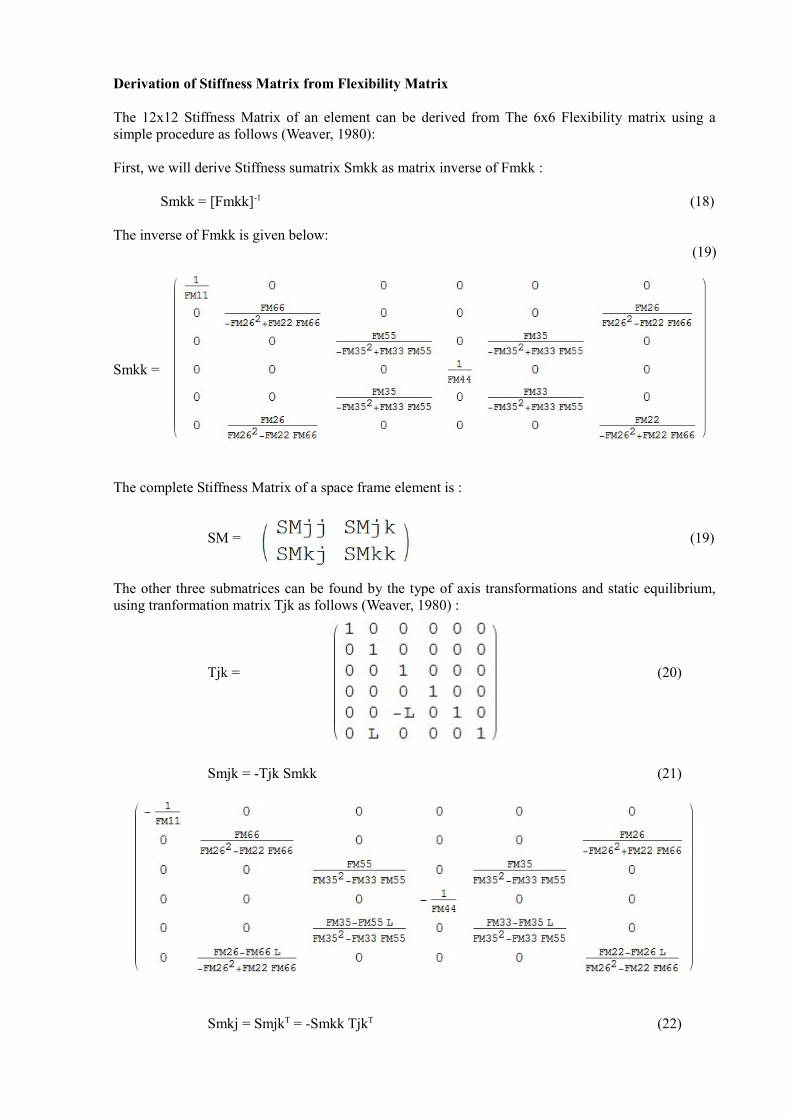
Derivation of Stiffness Matrix from Flexibility Matrix
The 12x12 Stiffness Matrix of an element can be derived from The 6x6 Flexibility matrix using asimple procedure as follows (Weaver, 1980):
First, we will derive Stiffness sumatrix Smkk as matrix inverse of Fmkk :
Smkk = [Fmkk]-1 (18)
The inverse of Fmkk is given below: (19)
Smkk =
The complete Stiffness Matrix of a space frame element is :
SM = (19)
The other three submatrices can be found by the type of axis transformations and static equilibrium,using tranformation matrix Tjk as follows (Weaver, 1980) :
Tjk = (20)
Smjk = -Tjk Smkk (21)
Smkj = SmjkT = -Smkk TjkT (22)
andSmjj = -Tjk Smkj = Tjk Smkk TjkT (23)
In Tena-Colunga's paper (1996), different equations for Smjk and Smjj are given, which can giveincorrect stiffness matrix compared to the matrix transformation method used above. Smjk is notnecessary to be symmetric, but the final stiffness matrix SM is always symmetric.
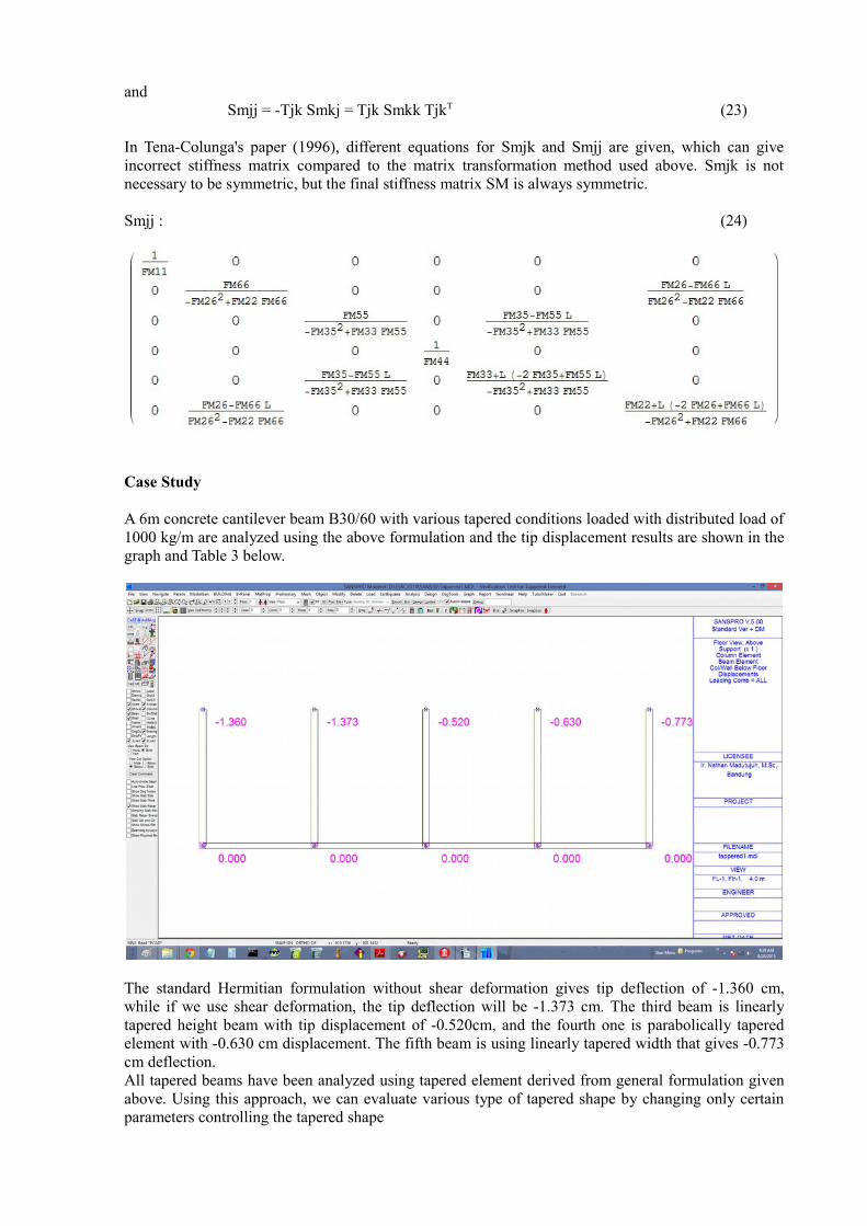
Smjj : (24)
Case Study
A 6m concrete cantilever beam B30/60 with various tapered conditions loaded with distributed load of1000 kg/m are analyzed using the above formulation and the tip displacement results are shown in thegraph and Table 3 below.
The standard Hermitian formulation without shear deformation gives tip deflection of -1.360 cm,while if we use shear deformation, the tip deflection will be -1.373 cm. The third beam is linearlytapered height beam with tip displacement of -0.520cm, and the fourth one is parabolically taperedelement with -0.630 cm displacement. The fifth beam is using linearly tapered width that gives -0.773cm deflection. All tapered beams have been analyzed using tapered element derived from general formulation givenabove. Using this approach, we can evaluate various type of tapered shape by changing only certainparameters controlling the tapered shape
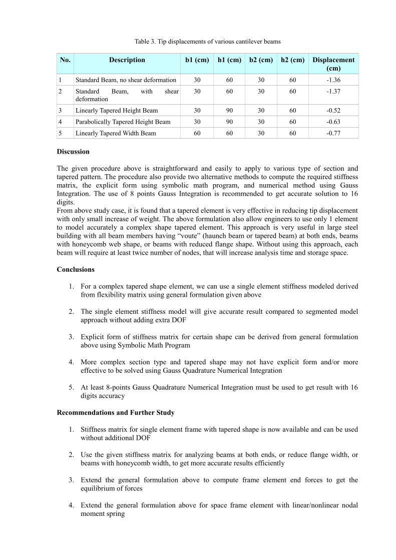
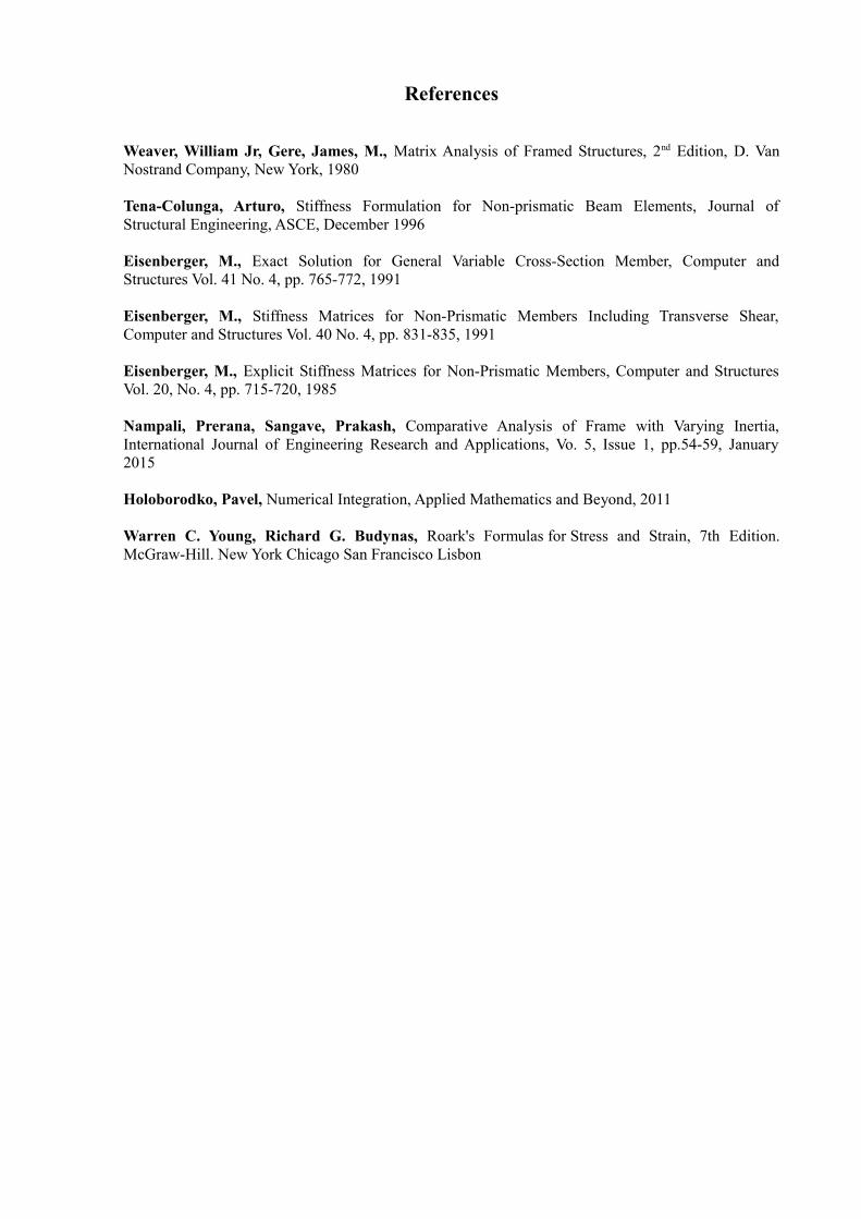
Table 3. Tip displacements of various cantilever beams
No. Description b1 (cm) h1 (cm) b2 (cm) h2 (cm) Displacement(cm)
1 Standard Beam, no shear deformation 30 60 30 60 -1.36
2 Standard Beam, with sheardeformation
30 60 30 60 -1.37
3 Linearly Tapered Height Beam 30 90 30 60 -0.52
4 Parabolically Tapered Height Beam 30 90 30 60 -0.63
5 Linearly Tapered Width Beam 60 60 30 60 -0.77
Discussion
The given procedure above is straightforward and easily to apply to various type of section andtapered pattern. The procedure also provide two alternative methods to compute the required stiffnessmatrix, the explicit form using symbolic math program, and numerical method using GaussIntegration. The use of 8 points Gauss Integration is recommended to get accurate solution to 16digits.From above study case, it is found that a tapered element is very effective in reducing tip displacementwith only small increase of weight. The above formulation also allow engineers to use only 1 elementto model accurately a complex shape tapered element. This approach is very useful in large steelbuilding with all beam members having “voute” (haunch beam or tapered beam) at both ends, beamswith honeycomb web shape, or beams with reduced flange shape. Without using this approach, eachbeam will require at least twice number of nodes, that will increase analysis time and storage space.
Conclusions
1. For a complex tapered shape element, we can use a single element stiffness modeled derivedfrom flexibility matrix using general formulation given above
2. The single element stiffness model will give accurate result compared to segmented modelapproach without adding extra DOF
3. Explicit form of stiffness matrix for certain shape can be derived from general formulationabove using Symbolic Math Program
4. More complex section type and tapered shape may not have explicit form and/or moreeffective to be solved using Gauss Quadrature Numerical Integration
5. At least 8-points Gauss Quadrature Numerical Integration must be used to get result with 16digits accuracy
Recommendations and Further Study
1. Stiffness matrix for single element frame with tapered shape is now available and can be usedwithout additional DOF
2. Use the given stiffness matrix for analyzing beams at both ends, or reduce flange width, orbeams with honeycomb width, to get more accurate results efficiently
3. Extend the general formulation above to compute frame element end forces to get theequilibrium of forces
4. Extend the general formulation above for space frame element with linear/nonlinear nodalmoment spring
References
Weaver, William Jr, Gere, James, M., Matrix Analysis of Framed Structures, 2nd Edition, D. VanNostrand Company, New York, 1980
Tena-Colunga, Arturo, Stiffness Formulation for Non-prismatic Beam Elements, Journal ofStructural Engineering, ASCE, December 1996
Eisenberger, M., Exact Solution for General Variable Cross-Section Member, Computer andStructures Vol. 41 No. 4, pp. 765-772, 1991
Eisenberger, M., Stiffness Matrices for Non-Prismatic Members Including Transverse Shear,Computer and Structures Vol. 40 No. 4, pp. 831-835, 1991
Eisenberger, M., Explicit Stiffness Matrices for Non-Prismatic Members, Computer and StructuresVol. 20, No. 4, pp. 715-720, 1985
Nampali, Prerana, Sangave, Prakash, Comparative Analysis of Frame with Varying Inertia,International Journal of Engineering Research and Applications, Vo. 5, Issue 1, pp.54-59, January2015
Holoborodko, Pavel, Numerical Integration, Applied Mathematics and Beyond, 2011
Warren C. Young, Richard G. Budynas, Roark's Formulas for Stress and Strain, 7th Edition.McGraw-Hill. New York Chicago San Francisco Lisbon
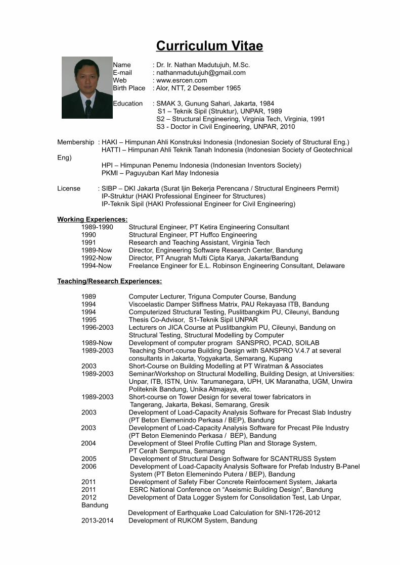
Curriculum VitaeName : Dr. Ir. Nathan Madutujuh, M.Sc.E-mail : [email protected] : www.esrcen.comBirth Place : Alor, NTT, 2 Desember 1965
Education : SMAK 3, Gunung Sahari, Jakarta, 1984 S1 – Teknik Sipil (Struktur), UNPAR, 1989
S2 – Structural Engineering, Virginia Tech, Virginia, 1991 S3 - Doctor in Civil Engineering, UNPAR, 2010
Membership : HAKI – Himpunan Ahli Konstruksi Indonesia (Indonesian Society of Structural Eng.) HATTI – Himpunan Ahli Teknik Tanah Indonesia (Indonesian Society of Geotechnical
Eng) HPI – Himpunan Penemu Indonesia (Indonesian Inventors Society) PKMI – Paguyuban Karl May Indonesia
License : SIBP – DKI Jakarta (Surat Ijin Bekerja Perencana / Structural Engineers Permit) IP-Struktur (HAKI Professional Engineer for Structures) IP-Teknik Sipil (HAKI Professional Engineer for Civil Engineering)
Working Experiences:1989-1990 Structural Engineer, PT Ketira Engineering Consultant1990 Structural Engineer, PT Huffco Engineering1991 Research and Teaching Assistant, Virginia Tech1989-Now Director, Engineering Software Research Center, Bandung1992-Now Director, PT Anugrah Multi Cipta Karya, Jakarta/Bandung1994-Now Freelance Engineer for E.L. Robinson Engineering Consultant, Delaware
Teaching/Research Experiences:
1989 Computer Lecturer, Triguna Computer Course, Bandung1994 Viscoelastic Damper Stiffness Matrix, PAU Rekayasa ITB, Bandung1994 Computerized Structural Testing, Puslitbangkim PU, Cileunyi, Bandung1995 Thesis Co-Advisor, S1-Teknik Sipil UNPAR1996-2003 Lecturers on JICA Course at Puslitbangkim PU, Cileunyi, Bandung on
Structural Testing, Structural Modelling by Computer1989-Now Development of computer program SANSPRO, PCAD, SOILAB1989-2003 Teaching Short-course Building Design with SANSPRO V.4.7 at several
consultants in Jakarta, Yogyakarta, Semarang, Kupang2003 Short-Course on Building Modelling at PT Wiratman & Associates1989-2003 Seminar/Workshop on Structural Modelling, Building Design, at Universities:
Unpar, ITB, ISTN, Univ. Tarumanegara, UPH, UK Maranatha, UGM, UnwiraPoliteknik Bandung, Unika Atmajaya, etc.
1989-2003 Short-course on Tower Design for several tower fabricators in Tangerang, Jakarta, Bekasi, Semarang, Gresik
2003 Development of Load-Capacity Analysis Software for Precast Slab Industry (PT Beton Elemenindo Perkasa / BEP), Bandung
2003 Development of Load-Capacity Analysis Software for Precast Pile Industry (PT Beton Elemenindo Perkasa / BEP), Bandung
2004 Development of Steel Profile Cutting Plan and Storage System, PT Cerah Sempurna, Semarang
2005 Development of Structural Design Software for SCANTRUSS System2006 Development of Load-Capacity Analysis Software for Prefab Industry B-Panel
System (PT Beton Elemenindo Putera / BEP), Bandung2011 Development of Safety Fiber Concrete Reinfocement System, Jakarta2011 ESRC National Conference on “Aseismic Building Design”, Bandung2012 Development of Data Logger System for Consolidation Test, Lab Unpar, Bandung Development of Earthquake Load Calculation for SNI-1726-2012 2013-2014 Development of RUKOM System, Bandung

2014 Development for LUSAS to LARSAP Bridge Data Conversion Program2015 Development of 3D Pile Settlement Analysis System using Mindlin Equation