general Electric - Ge Grid Solutions Online...
15
. INSTRUCTIONS GEK-15008A ST-100” ADJUSTABLE FREQUENCY AC DRIVE 3S7506FV600 AND -FV700 SERIES *TRADEMARK OF GENERAL ELECTRIC COMPANY, U.S.A. GENERAL@ ELECTRIC
Transcript of general Electric - Ge Grid Solutions Online...
. INSTRUCTIONS GEK-15008A
ST-100” ADJUSTABLE FREQUENCY AC DRIVE
3S7506FV600 AND -FV700 SERIES
*TRADEMARK OF GENERAL ELECTRIC COMPANY, U.S.A.
GENERAL@ ELECTRIC
GEK- 15008 ST-100 AdJustable Frequency AC Drive 3S7506FV600 and -FV700 Series
CONTENTS
PAGE
INTRODUCTION ..................................................
DESCRIPTION .................................................... Power Unit ................................................. Motor ...................................................... Control Station ..............................................
SPECIFICIATIONS ............................................... Input ....................................................... output ..................................................... Accuracy .................................................. Protection .................................................
3
RECEIVING, HANDLING AND STORAGE ........................... 4
INSTALLATION .................................................. Power Unit Mounting ......................................... Control Station .............................................. Interconnection ............................................. Final Check .................................................
OPERATION AND ADJUSTMENT .................................. Initial Operation ............................................ Normal Operation ............................................
THEORY OF OPERATION .........................................
MAINTENANCE .................................................. Replacing Power Unit Panel Assembly .........................
TROUBLESHOOTING AND REPAIR ................................. Checking Silicon Controlled Rectifiers ......................... Checking Silicon Diodes ....................................... Replacing Stud Mounted SCR’s and Diodes ...................... Power Unit Test Procedure ................................... Replacing Printed Circuit Boards ............................
5 5 5
6
7 7
7 7 7 8 8
10
RENEWAL PARTS . . . . . . . . . . . . . . . . . . . . . . . . . . . . . . . ..*............. 11
These instructions do not purport to cover aI! details or voriofions in equipment nor to provide for every possible confingency b
be met in connection with insfollofion, operation or maintenance. Should further informofton be dewed or should porficulor problems
arise whrch ore not covered sufficienfly for the purchaser’s purposes, fhe matter should be referred to the General Electrrc Company
GEK-15008
ST-100 ADJUSTABLE FREQUENCY AC
3S7506FV600 SERIES
INTRODUCTION
This manual contains the installation, operation, and maintenance instructions for the 3S7506FV600 and -FV700 series ST-100 adjustable frequency AC drives. It describes the theory of operation of the basic power unit and recommended troubleshooting procedures. Auxiliary circuits and equipment not described in this manual will be included as supplemental material.
DESCRIPTION The ST-100 adjustable frequency drive is a packaged, all solid state drive for controlling the speed of AC motors. The AC input is converted to adjustable DC power. A single analog reference signal controls the output frequency and the DC level into the inverter section of the power unit. The resulting output is a highly regulated three-phase,constant volts per hertz for speed control of induction or synchronous motors over a wide speed range.
A basic ST-100 drive will normally include a power unit, motor, and operator’s control station.
POWER UNIT
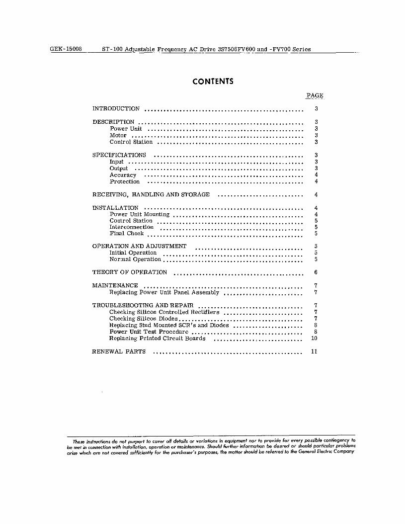
The power unit consists of semiconductors and related static components arranged on an extruded aluminum heat sink mounted in a NEMA 1 ventilated enclosure. (See Figure 1.) A three-phase circuit breaker or dis- connect switch is provided to remove input power. Optional output voltmeter, ammeter, and test jacks may also be provided.
Most of the control circuit components are contained on printed circuit boards which are mounted on a hinged panel for ease in assembly and maintenance. The primary power conversion components are sili- con controlled rectifiers (SCR’s) used to convert the input AC to adjustable DC and in a bridge arrange- ment that inverts the DC to stepped wave AC.
MOTOR
An induction or synchronous reluctance motor may be supplied depending on the application requirements. The motor will supply a constant torque load over the operating frequency range.
CONTROL STATION
The type of operator’s control station supplied will depend on the application. A control station for single drive applications will normally include a speed-set- ting potentiometer and start- stop pushbuttons. For more complex applications where several drives are cascaded to co-ordinate sections in a process, a desk- type console may be provided.
AND -FV700
SPECIFICATIONS
INPUT
FV600 Series - 208Y/120 AC i 5%, 3 phase, 4 wire, 60 Hz.
FV700 Series - 416Y/240 AC f 5% 3 phase, 4 wire, 60 Hz.
OUTPUT
FV600 Series - Rated lOKVA, 3 phase, continuous duty, suitable for 5 H. P. at maximum frequency.
Figure 1. Typical Power Unit in Enclosure
3
FV700 Series - Rated BOKVA, 3 phase, continuous duty, suitable for 10 H. P. at maximum frequency.
Operating frequency - 6 to 120 Hz.
FV600 Series Gutput Voltage - 100 volts at maximum frequency, constant volts per Hz.
FV700 Series Output Voltage - 200 volts at maximum frequency, constant volts per Hz.
ACCURACY
Long Term Drift - Frequency drift less than *20/o of set frequency with analog reference from potentiometer.
Optional external frequency reference for drift accur- acies of *O. 05% or *O. 01% of set frequency.
Speed Regulation - &OS from no load to full load with synchronous motors.
Environmental Conditions
Storage Range - 0” C to 65°C
Operating Range - 10” C to 45” C
PROTECTION
Circuit Breaker - Provides short circuit protection (10,000 amps interrupting capacity) for the power unit and also serves as a disconnect means to remove in- put power.
Fuses - Provide short circuit protection for the solid state devices in the power unit. Current Trip - An internal static circuit provides fault current protection for semi-conductor devices in the power unit. Current Limit - Limits the output current for tem- porary overloads.
Undervoltage - An internal static circuit protects against automatic restarting following AC power interruption and also protects the power unit and motor if a low voltage condition exists during nor- mal running operation. Phase Sequence - The unit is not phase sensitive, therefore no need for concern when connecting the AC supply lines.
Acceleration
Time rate acceleration and deceleration is standard.
RECEIVING, HANDLING AND STORAGE Place the equipment under adequate cover immediately upon receipt. The packing cases are not suitable for outdoor or unprotected storage. Examine the shipment carefully on its arrival and check it against the packing list. Promptly report any shortage or damage incurred during shipment to the carrier and to the nearest Gen- eral Electric Company Sales Office. Particular care should be exercised to prevent small parts from being mislaid or thrown away with the packing material.
If the equipment is not to be used as soon as it is un- packed, it should be stored in a clean, dry area and protectedagainst accidental damage. Particular care shouldbe exercised to avoid storage in a location where construction work is in progress.
INSTALLATION
Mounting and Interconnection of the ST- 100 drive com- ponents is described in this section. When installing the equipment, check all accessible factory connections for tightness, since connections maybecome loose dur- ing shipping or storage.
POWER UNIT MOUNTING Wall mount the power unit by using the mounting brack- ets at top and bottom of the enclosure or by removing the panel assembly and mounting the enclosure using the holes provided. (See outline drawing for dimen- sions. )
The unit can be floor mounted by using a mountmg base that does not restrict air flow into the bottom of the enclosure.
Use the following procedure to remove the panel as- sembly for mounting:
1. Remove front cover from enclosure by loosen- ing screw at each corner.
2. Disconnect the wires from the circuit breaker, terminal board and ground stud which are a part of the enclosure.
3. Remove the bolts holding the power unit panel assembly and slide the unit out of the enclosure. There is a latch mechanism near the top of the enclosure that must be actuated to remove the power unit completely from the enclosure.
4. Wall mount the enclosure using the two mount- ing holes at the top back of the enclosure and the single mounting hole at the bottom. The holes are suitable for l/2 inch mounting bolts. (See outline drawing for dimensions. )
5. Slide the power unit panel assembly back into the enclosure, replace the mounting bolts and recon- nect all wires. A hole is provided at the top of the panel for a lifting hook that can be used to lift the unit.
Install the power unit in a well-ventilated location which is not subject to ambient temperature above 45°C (113°F). Never install the power unit where hazardous, inflammable or combustible vapors, or dust are present.
The power unit is convection-cooled. Air en- ters through the bottom of the enclosure and exits
GEK-15008 ST-100 Adjustable Frequency AC Drive 3S7506FV600 and -FV700 Series
4
ST-100 Adjustable Frequency AC Drive 3S7506FV600 and -FV700 Series GEK- 15008
through the upper part of the front and sides. Make sure there is ample clearance around the outside of the enclosure to allow a normal flow of cooling air.
CONTROL STATION
Mount the control station using hole locations and over-all dimensions shown on the outline drawing supplied with the equipment. Make sure the enclosure type is suitable for the environment in the mounting area.
INTERCONNECTION
The equipment has been designed to prevent internal- ly generated noise from causing mis-operation of sens- itive control circuits. It is equally as important to prevent externally generated noise from getting into the control circuits. This can be done by following the interconnection diagram supplied with the equip- ment. It will show the recommended routing of con- trol and power leads, wires that must be shielded, and recommended wire sizes.
IMPORTANT
Read all notes and instructions on the interconnection diagram before proceeding.
Input Voltage Connection:
1. The three line connections are made at the cir- cuit breaker terminals and the neutral wire connects to the ground stud on the enclosure.
2. Make certain that the input voltage and fre- quency of the available power agree with the rating on the power unit nameplate. If the available supply is other than specified, it will be necessary to use a transformer. The required transformer rating is approximately 3KVA per horsepower based on the maximum horsepower supplied at top frequency.
3. It is recommended that a fused disconnect switch be installed in the AC power lines ahead of the power unit. (See interconnection diagram for recommended fuse rating. )
Grounding:
The ground stud should be connected directly to plant ground. If a transformer is used, the neutral wire is connected to the ground stud and grounded at that point only. It is also recommended that the control station and motor be grounded in accordance with NEC and/or local code requirements.
FINAL CHECK
1. Interconnecting Wiring
Nearly all of the problems encountered in the initial startup of any system is caused by improper
interconnecting wiring. If difficulty is encountered, the first step should be a careful recheck of all inter- connecting wiring.
2. Loose Connections
Loose connections may cause malfunctions; make sure all connections are tight.
3. Wires
Wires may be broken due to mishandling of the control or excessive vibrations and shock (e. g. during transportation). Usually a broken wire is fairly obvious after a few minutes inspection (with power switched off).
OPERATION, AND ADJUSTMENT INITIAL OPERATION
When all connections have been made correctly, the drive will be ready to operate. Apply input voltage to the power unit by closing the circuit breaker., Set the speed reference for minimum operating frequency, Press the start button and gradually increase and decrease the output frequency over the required operating range by changing the speed reference.
The power units internal oscillator frequency range, volts per hertz ratio and voltage boost at low frequency have been factory adjusted to match the motor supplied. Do not change these adjustments. Acceleration and de- celeration times will be set for 20 seconds unless other times are specified when the equipment is ordered.
NORMAL OPERATION
When operating properly, the drive can be started by pressing the start button, with the speed reference set for any output frequency within the normal operating range. The power unit frequency and motor speed will accelerate at a linear timed rate from zero to the set point while maintaining the proper volts per hertz ratio. When the stop button is pressed, frequency and motor speed will decelerate to zero also at a linear timed rate. If input power is removed while the drive is operating, the frequency will immediately go to zero and the motor will coast to a stop at a rate determined by the inertia and friction in the drive system.
The sync light located on the meter panel (when ex- ternal frequency reference is used) will indicate when the power unit internal oscillator is synchronized with the external frequency reference. This is a two sec- tion light and when both sections are “on”, the drive is synchronized. If several motors are supplied from a single power unit, starting one motor while the others are running may cause the current trip circuit to shut down the drive. When this happens the drive can be restarted by simply pressing the start button.
When several power units are being controlled from a single external frequency reference, individual units can be started and stopped without affecting the oper- ation of others.
GEK- 15008 ST-100 Adjustable Frequency AC Drive 3S7506FV600 and -FV700 Series
THEORY OF OPERATION
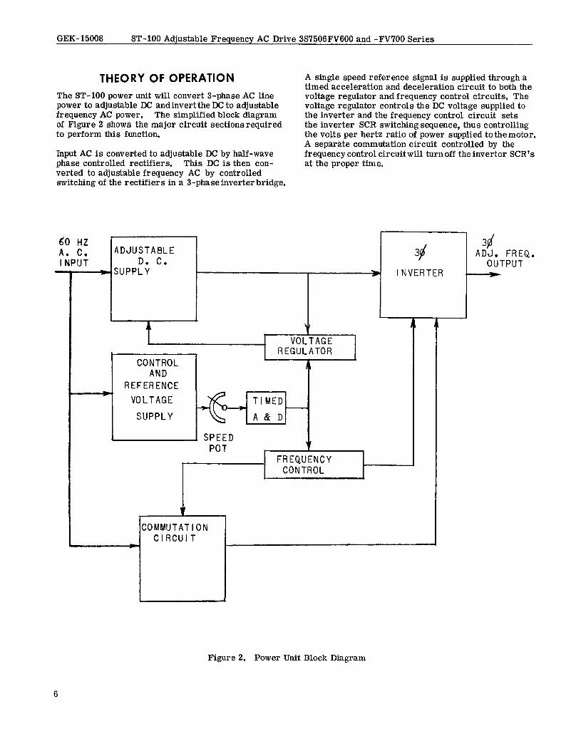
The ST-100 power unit will convert J-phase AC line power to adjustable DC andinvert the DC to adjustable frequency AC power, The simplified block diagram of Figure 2 shows the major circuit sectionsrequired to perform this function.
Input AC is converted to adjustable DC by half-wave phase controlled rectifiers. This DC is then con- verted to adjustable frequency AC by controlled switching of the rectifiers in a 3-phase inverter bridge.
A single speed reference signal is supplied through a timed acceleration and deceleration circuit to both the voltage regulator and frequency control circuits. The voltage regulator controls the DC voltage supplied to the inverter and the frequency control circuit sets the inverter SCR switching sequence, thus controlling the volts per hertz ratio of power supplied to the motor. A separate commutation circuit controlled by the frequency control circuit will turn off the inverter SCR’s at the proper time.
L
60 HZ A. C. ADJUSTABLE INPUT D. C. 38
c- SUPPLY W INVERTER
Y b
-
1 VOLTAGE 1
1 VOLTAGE
SUPPLY
1 SPEED POT
FREQUENCY CONTROL
i
COMMUTATION CIRCUIT
3a( ADJ. FREQ.
OUTPUT F
Figure 2. Power Unit Block Diagram
ST-100 Adjustable Frequency AC Drive 3S7506FV600 and -FV700 Series GEK-15008
MAINTENANCE
Maintenance is primarily a matter of routine inspec- tion and good housekeeping. The inside of the enclo- sure should be checked at regular intervals to make sure it is free of dust or other foreign matter. The panel is the heat sink and should be kept clean to pro- vide maximum heat dissipation.
If a power unit failure should occur, down time can be held to a minimum by replacing the complete panel assembly. All power unit components except the cir- cuit breaker (plus dropping resistors on FV700 series) are mounted on the panel assembly which can be eas- ily replaced. Before replacement is made, check all leads connected between the power unit, motor and contr 01 station, Make sure there are no short cir- cuits and that all connections are tight.
REPLACING POWER UNIT PANEL ASSEMBLY
[W*RNING\
Make sure AC line power is removed from the power unit before touching internal parts.
1. Disconnect input power leads from the load side of the circuit breaker.
2. Disconnect leads from the terminal board(s) at top of the enclosure.
3. Disconnect incoming control wires from the main terminal board. Mark the leads so they can be replaced on the correct terminal points.
4. Remove the four mounting bolts.
5. Carefully slide the power unit out of the enclosure by means of the handles provided.
6. Slide the new unit into the enclosure. Replace mounting bolts and all wiring. Make sure that all connections are tight.
TROUBLESHOOTING AND REPAIR If a spare panel assembly is not available for replace- ment, it may be possible to repair the defective unit. Printed circuit boards containing the control circuitry and semiconductor components mounted on the heat sink can be replaced without special training or equip- ment. There are some simple checks that can be made, using a volt/ohmmeter, to help locate the trouble. Also, by observing the symptoms and indi- cations that are available, it may be possible to iso- late the defect to a printed circuit board or semicon- ductor component. If the defect is not found by these simple checks and observations, the printed circuit boards should be replaced. Troubleshooting and re- pair of printed circuit boards is not recommended. Return the defective printed circuit board to the fac-
tory for repair after calling your GE sales office for return instructions.
The power unit is equipped with special protective circuits to trip the unit off in case of undervoltage, heavy overloads, or short circuits on the output. These same protective circuits could also trip the unit off if the control circuits fail to operate properly. Repeated tripping will occur each time the power unit is started as long as the trouble exists. By observing the meters located on the meter panel, it may be pos- sible to determine if the trouble is caused by exces- sive load current or a circuit malfunction.
Additional protection for the power unit is provided by fuses 1FU and 2FU. Referring to the elementary diagram supplied with the equipment, it can be seen that fuse 1FU protects the input SCR’s and 2FU pro- tects the commutation circuit componemts. There- fore, observing the fuse which has blown will be of some help in locating the trouble.
Replace fuses 1FU and 2FU with the exact same type and rating as supplied with the equipment. No substitution can be made.
The power diodes and SCR’s are mounted on aluminum blocks which in turn are affixed to the heat sink. The heat sink itself is at ground potential but the mounting blocks are at some potential above ground. The mount- ing blocks are electrically isolated from the heat sink, so care must be exercised when working near the small blocks.
CHECKING SILICON CONTROLLED RECTIFIERS
The SCR’s are provided with special current and volt- age protection. A malfunction of these protective de- vices under the right conditions could result in an SCR failure. This failure would normally be to a short, which can be found with an ohmmeter on “Times 1” scale.
CHECKING SILICON DIODES
The characteristics of a silicon diode to block current in one direction and pass current freely in the other direction is used in a simple ohmmeter check. Con- nect ohmmeter leads across diode to be checked. When the meter leads are reversed, the indicated resistance should change from infinite to some very low value. (Low value will vary with different instruments).
NOTE
Silicon diodes will usually fail either to a short or an open which will be quickly dis- covered with the above check.
7
GEK- 15008 ST-100 Adjustable Frequency AC Drive 3S7506FV600 and -FV700 Series
In removing or replacing any SCR or diode, use a small soldering iron of not more than 35 watts. Do not apply soldering iron heat to rectifier terminal any longer than neces- sary.
REPLACING STUD MOUNTED SCR’s AND DIODES
1. Remove defective rectifier from heat sink and throughly clean the area around the mounting hole.
2. Apply silicon grease (Dow-Corning #3) to new rectifier stud before mounting on heat sink.
3. Tighten the rectifier to assure a firm con- tact between rectifier and heat sink but don’t overdo it. Excessive stress may damage the rectifier. If a torque wrench is available, tighten as follows:
a. Large SCR’s and rectifiers - 70 lb-in. max.
b. Small rectifiers - 20 lb-in. max.
POWER UNIT TEST PROCEDURE
The possibility exists that the failure of a component in one section may cause misoperation in another section of the power unit. For this reason a definite procedure must be followed in checking circuits and components. The following test procedure should be used. Refer to the elementary and wiring diagrams supplied with the equipment and Figure 3 to locate components and circuit points.
1, Open circuit breaker. (Always check with a voltmeter to make sure that voltage has been removed.)
2. Remove both fuses, 1FU and 2FU.
3. Loose connections can cause misoperation. Check all internal and external lead connections as- sociated with the drive to make sure they are tight.
4. Check all power semiconductor components mounted on the head sink with an ohmmeter.
It is possible that in cases where a bus bar is being used to connect three diodes or SCR’s together, if a single SCR or diode is shorted, each of the com- ponents might indicate a short. It will then be neces- sary to remove the bus bar to locate the failed com- ponent.
If an output bridge SCR (4-9 SCR) is shorted, more than one will indicate a short with the motor leads connected. It will be necessary to disconnect the motor to determine the one that is actually shorted.
5. If the above checks are all satisfactory, close the circuit breaker applying power to the unit.
8
Be careful not to come in contact with live parts.
6. Voltage Checks - All measurements to be made with respect to circuit 100 (terminal 14 on term- inal board) ana have a tolerance of f 10% unless other- wise stated.
a. Check the incoming line voltage. Measure the line to line and line to neutral voltages. Be sure to check all three phases.
FVGOO Series FV700 Series
L - L = 208 VAC L - L = 416 VAC L - Neutral = 120 VAC L - Neutral = 240 VAC
These voltages should be within i5%. If not, take whatever corrective action is necessary to bring the voltage within these limits.
b. Measure the commutating bus voltage circuit 24 (left terminal of 2FU).
FV600 Series
+ 160 VDC
FV700 Series
+320 VDC
c. Check the following control voltage at the main terminal board.
CIRCUIT # TERMINAL # + VDC * 10%
43 4and22 Zero 102 7 18V 25 8 and 15 24V 50 13 Approx. 1V 14 19 Zero
If the 24 VDC bus is low, a possible cause could be a shorted zener diode 9BD - 12BD or capacitor 18C (68MFD) on main printed circuit board or open resistor 9R (mounted on back of swinging frame). If there is a voltage at circuit 50 which is greater than 2. 5 VDC, then resistor 3R or diode 20D could be open. To check, remove power from unit and with an ohmmeter, check the resistance between terminals 3 and 13 of the term- inal board. With meter leads oriented in one direction, the resistance should be low (less than 10 ohms) and in the other direction, some high value. NOTE: This procedure also checks 1CR contact. If the resistance checks indicates an open circuit, replace the power supply PCB. If the I8VDC line is low, a possible cause could be shorted zener diodes 3BD - 5BD, transistor 4Q on power supply PCB or open resistor 8R (mounted on back of swinging frame).
d. If the voltage checks in sections b and c are within tolerance, leaving fuses 1FU and 2FU out of the circuit, press the “start” button. Set “speed adjust” for approximately 50% speed and check the following
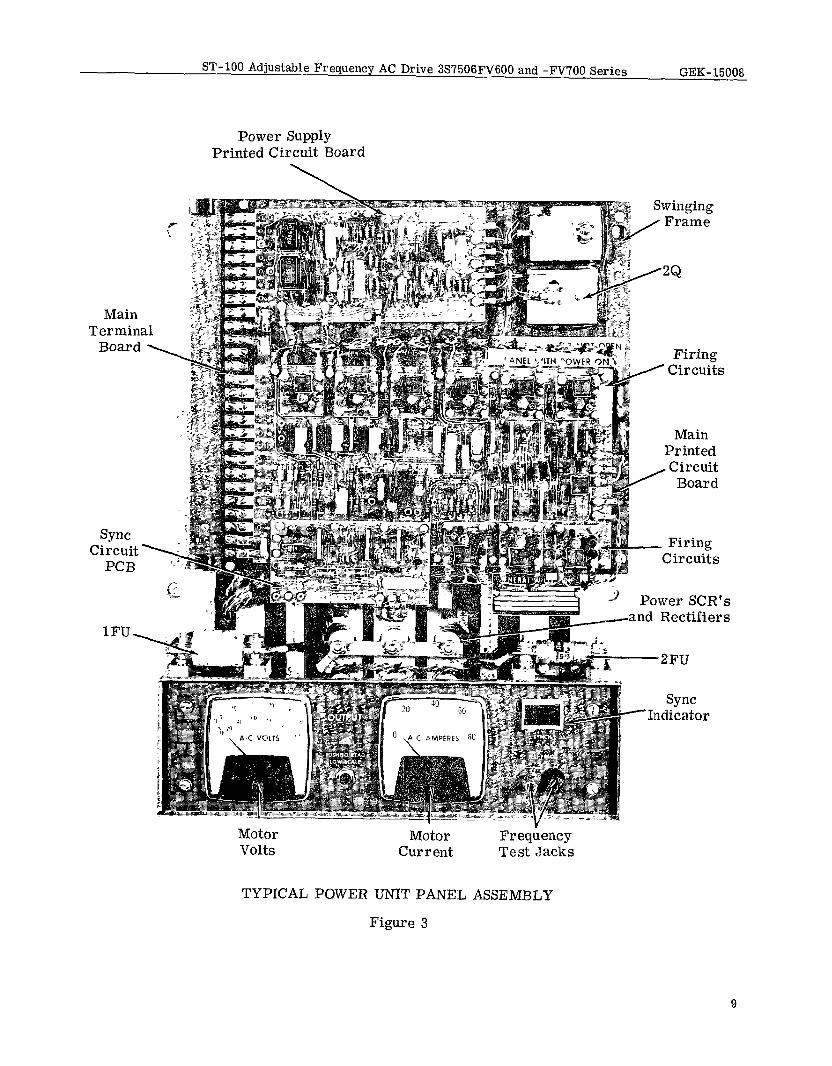
ST-100 Adjustable Frequency AC Drive 3S7506FV600 and -FVi’OO Series GEK-15008
Power Supply Printed Circuit Board
\
Main Termin:
Board
Sync Circuit
PCB
*P Firing Circuits
Main Printed
, Circuit Board
Firing Circuits
Power SCR’s -and Rectifiers
Motor Volts
Motor Current
Fr eqiency Test Jacks
TYPICAL POWER UNIT PANEL ASSEMBLY
Figure 3
sync -Indicator
9
GEK-15008 ST-100 Adjustable Frequency AC Drive 3S7506FV600 and -FV700 Series
control voltages at the main terminal board. Allvolt- age readings to be made with respect to circuit 100 (terminal 14).
CIRCUIT #
43
50
TERMINAL # +VDC +lO%
4 and 22 6V (see note below)
13 45v
NOTE
If an external reference frequency is being used to control the speed of this equipment, rather than a potentiometer, the voltage reading at circuit 43 will be approximately 3 V DC since the output of the sync board is essentially a square wave.
If the 45 volt bus is low, check for a shorted transis- tor on the firing circuit boards, shorted transistor 2Q (top right hand side of swinging frame), or zener diodes 1BD and 2BD (on power supply board).
The transistor to check on the firing circuit board is the one in the metal case, The transistor case will be very hot to the touch. If so, replace the firing circuit board.
7. Firing Circuit Check:
With the unit energized and the speed adjust set for an output frequency of approximately 60 cycles, connect the negative lead of the voltmeter on circuit 100 (terminal 14 of terminal board) and the positive lead on the top lead of the 47 ohm resistor of each of the nine firing circuit boards. It is located next to the metal can transistor and has a yellow band for its first color band.
Be careful not to short any components on the board.
A reading of 0.5 to 1. 5 volts DC on the first three firing circuit boards from left to right at the top of the main printed circuit board and a reading of 1.5 to 2.5 volts DC on the remaining six boards is an indication that the firing circuits are operating. This simple check will not indicate all possible defects in these circuits, but should be adequate in most cases.
8. Synchronizing Circuit Check (if used)
When the speed is to be controlled by an ex- ternal reference frequency, a synchronizing (frequency discriminator) board is required and is mounted on the bottom left edge of the main printed circuit board. With 1FU and 2FU out of the circuit, the start circuit ener- gized, and the “speed adjust” set for approximately 20%
10
speed, observe the sync light on the meter panel. If both sections of the light are on and stable, no further check of the board is required. If the light is unstable, or only one section of the light is on, replace the sync board. If the same results occur, replace the main printed circuit board.
9. Commutation Circuit Check:
a.
b.
C.
Open circuit breaker.
Turn “speed adjust” to zero set point.
Replace fuse 2FU only.
Be careful not to touch fuse clips since ca- pacitor 35C may not be completely discharged. Check to make sure that voltage between fuse clips and heat sink is zero before proceedmg.
d. Close circuit breaker and press the START button.
e. Turn “speed adjust” clockwise until you hear the commutation circuit operate. This will be a clicking sound.
f. If fuse 2FU blows or the circuit does not operate, recheck lD, 2D, 3D, 14D, 15D, 1OSCR and 11SCR. Also check for loose connections in the commutation circuit. Before checking diodes and SCR’s, make certain all power has been removed from the panel.
If the defect has not been found, replace the printed circuit boards.
REPLACING PRINTED CIRCUIT BOARDS
B
Handle printed circuit boards very carefully to prevent damage to board or components.
1. Auxiliary Boards: a. Remove all leads attached to the defective
board. b. Remove defective auxiliary board from
main PC board by removing mounting screws.
c. Install the replacement board and replace
is in place under the board and all screws are tight.
2. Power Supply Board:
a. Remove all leads attached to the defect- ive board, Where necessary, tag leads to make sure they will be reconnected to the same points on the replacement board.
ST-100 Adjustable Frequency AC Drive 3$7506FV600 and -FV700 Series GEK- 15008
b. Remove board mounting screws.
c. The power supply board can now be re- moved by loosening the terminal board screws,
d. Install the replacement board and re-
a complete board assembly is not available for re- placement, the auxiliary boards can be transferred to a new main board. The same procedure described in 2 can be used to remove and replace the main PC board assembly.
RENEWAL PARTS place all mounting screws and leads. Make sure all screws are tight. Should a component fail, a replacement part can be
ordered from the nearest sales office of the General 3. Main Printed Circuit Board: Electric Company. When ordering renewal Parts,
specifiy the quantity required, give the catalogue In order to save time in replacing the main numbers and describe the required parts in detail.
PC board, it is recommended that the completeboard In addition, give the 35 model number and the com- assembly including auxiliary boards be replaced. If plete nameplate rating of the equipment,
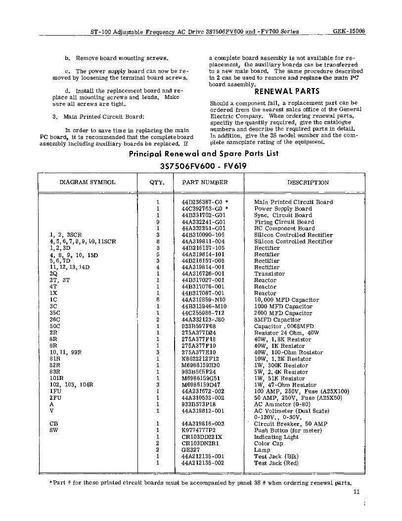
Principal Renewal and Spare Parts List
3S7506FV600 - FV619
DIAGRAM SYMBOL QTY. PART NUMBER DESCRIPTION
1, 2, 3SCR 4,5,6,7,8,9,lO,llSCR 1,2,3D 4, 8, 9, 10, 15D 5,6,7D 11,12, 13, 14D 2Q 2T, 3T 4T 1x 1c 3c 35c 36C 5oc 2R 8R 9R lO,ll, 99R 81R 82R 83R 1OlR 102, 103, 104R 1FU 2FU A V
CB SW
1 44D23638’7-GO * Main Printed Circuit Board 1 44(3392763-GO * Power Supply Board 1 44B331702-GO1 Sync. Circuit Board 9 44A332241-GO1 Firing Circuit Board 1 44A332251-GO1 RC Component Board 3 44B310090- 105 Silicon Controlled Rectifier 8 44A319811-004 Silicon Controlled Rectifier 3 44B216157-105 Rectifier 5 44A319814-101 Rectifier 3 44B216157-005 Rectifier 4 44A319814-001 Rectifier 1 44A316726-001 Transistor 1 44B317027-001 Reactor 1 44B317076-001 Reactor 1 44B317087-001 Reactor 6 44A319859-NlO 10,000 MFD Capacitor 1 44B313946-Ml0 1000 MFD Capacitor 1 44C255986-712 2600 MFD Capacitor 2 44A332123-J80 8MFD Capacitor 1 933B597F68 Capacitor 0 0068MFD 1 275A377D24 Resistor 24 Ohm, 40W 1 275A377F18 4OW, 1.8K Resistor 1 275A377FlO 4OW, 1K Resistor 3 275A377310 4OW, loo-Ohm Resistor 1 K8622212F12 lOW, 1.2K Resistor 1 M6986159H30 lW, 300K Resistor 1 983B565F24 5W, 2.4K Resistor 1 M6986159G51 lW, 51K Resistor 3 M6986159D47 lW, 47-Ohm Resistor 1 448231672-002 100 AMP, 25OV, Fuse (A25XlOO) 1 448310533-002 50 AMP, 25OV, Fuse (A25X50) 1 933B573Pl8 AC Ammeter (O-80) 1 44A319812-001 AC Voltmeter (Dual Scale)
o-12ov. ) o-3ov. 1 44A319816-003 . Circuit Breaker, 50 AMP 1 K9774777P2 Push Button (for meter) 1 CR103DD221X Indicating Light 2 CR103DN2Rl Color Cap 2 GE327 Lamp 1 44A212135-001 Test Jack (Blk) 1 44112 12 135-002 Test Jack (Red)
*Part # for these printed circuit boards must be accompanied by panel 3S # when ordering renewal parts. 11 1
GEK-15008 ST-100 Adjustable Frequency AC Drive 3S7506FV600 and -FV700 Series
Principal Renewal and Spare Parts list
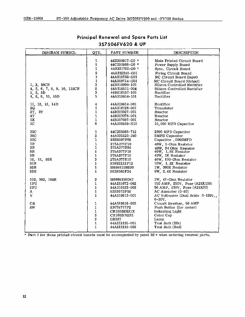
3S7506FV620 & UP
DIAGRAM SYMBOL QTY. PART NUMBER DESCRIPTION
1 44D331917-GO * Main Printed Circuit Board 1 44C331808-GO * Power Supply Board 1 44B331702-GO * Sync. Circuit Board 9 44A332241-GO1 Firing Circuit Board 1 44A318750-GO1 RC Circuit Board (Input) 1 4419318714-001 RC Circuit Board (Output)
1, 2, 3SCR 3 44B310090-105 Silicon Controlled Rectifier 4, 5, 6, 7, 8, 9, 10, 1lSCR 8 44A319811-004 Silicon Controlled Rectifier 1, 2, 3D 3 44B216157-105 Rectifier 4, 8, 9, 10, 15D 5 44A319814-101 Rectifier
11, 12, 13, 14D 4 44A319814-001 Rectifier ZQ ZT, 3T :
44A316726-001 Transistor 44B31702’7-001 Reactor
4T 1 44B317076-001 Reactor 1x 1 44B317087-001 Reactor 1c 6 44A319859-N10 10,000 MFD Capacitor
35c 1 44C255986-712 2600 MFD Capacitor 36C 2 44A332123-580 8MFD Capacitor 5oc 1 933B597F68 Capacitor .0068MFD 3: : 275A377ClO
275A377D24 40-W, l-Ohm Resistor
8R 1 275A377F18 4OW, 24 Ohm Resistor 4OW, 1. 8K Resistor
9R 1 275A377FlO 4OW, 1K Resistor 10, 11, 99R 3 275A.377310 4OW, loo-Ohm Resistor 81R 1 K8622212F12 lOW, 1.2K Resistor 82R 1 M6986159H30 lW, 300K Resistor 83R 1 983B565F24 5W, 2.4K Resistor
102, 103, 104R 3 M6986159D47 lW, 47-Ohm Resistor 1FU 1 44A231672-002 100 AMP, 25OV, Fuse (A25XlOO) 2FU 1 44A310533-002 50 AMP, 25OV, Fuse (A25X50) A 1 933B573P18 AC Ammeter (O-80) V 1 44A319812-001 AC Voltmeter (Dual Scale 0-12OV.,
o-3ov. CB 1 44A319816-003 Circuit Breaker, 50 AMP SW 1 K9774777P2 Push Button (for meter)
1 CRl03DDZZlX Indicating Light 2 CR103DNZRl Color Cap 2 GE327 Lamp 1 44A212135-001 Test Jack (Blk) 1 44A212135-002 Test Jack (Red)
Part # for these printed circuit boards must be accompanied by panel 3s # when ordering renewal parts.
12
ST-100 Adjustable Frequency AC Drive 3S7506FV600 and -FV?OO Series GEK- 15008
Principal Renewal and Spare Parts List
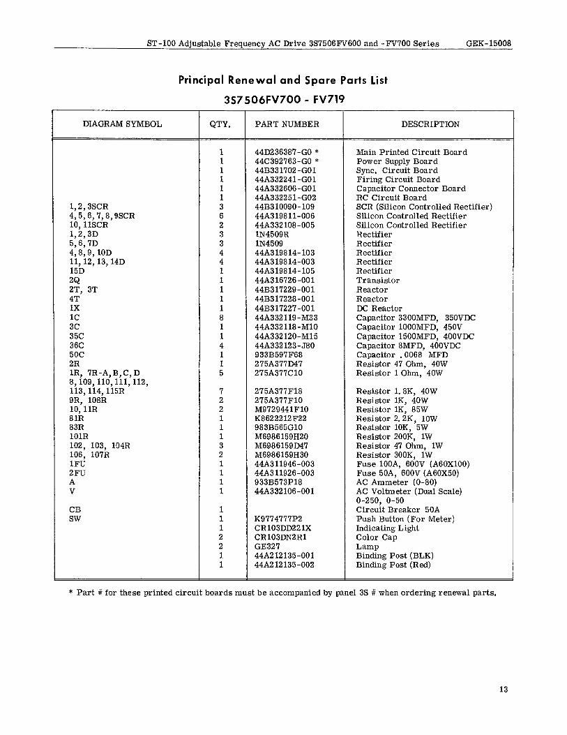
3S7506FV700 - FV719
DIAGRAM SYMBOL QTY. PART NUMBER DESCRIPTION
1,2,3SCR 4,5,6,7,8,9SCR 10,llSCR 1,2,3D 5,6,7D 4,8,9,10D 11,12,13, 14D 15D 2Q 2T, 3T 4T 1x 1c 3c 35c 36C 5oc 2R lR, ‘IR-A,B,C, D 8,109,110,111,112, 113,114,115R 9R, 108R 10,llR 81R 83R 101R 102, 103, 104R 106, 107R 1FU 2FU A V
CB SW
1 44DZ36387-GO * Main Printed Circuit Board 1 44C392763-GO * Power Supply Board 1 44B331702-GO1 Sync. Circuit Board 1 44A332241-GO1 Firing Circuit Board 1 44A332606-GO1 Capacitor Connector Board 1 44A332251-GO2 RC Circuit Board 3 44B310090- 109 SCR (Silicon Controlled Rectifier) 6 44A319811-006 Silicon Controlled Rectifier 2 44A332108-005 Silicon Controlled Rectifier 3 lN4509R Rectifier 3 lN4509 Rectifier 4 44A319814-103 Rectifier 4 44A319814-003 Rectifier 1 44A319814-105 Rectifier 1 44A316726-001 Transistor 1 44B317229-001 Reactor 1 44B317228-001 Reactor 1 44B317227-001 DC Reactor 8 44A332119-M33 Capacitor 3300MFD, 350VDC 1 44A332118-Ml0 Capacitor lOOOMFD, 450V 1 44A332120-Ml5 Capacitor 1500MFD, 400VDC 4 44A332123-580 Capacitor 8MFD, 400VDC 1 933B597F68 Capacitor .0068 MFD 1 275A377D47 Resistor 47 Ohm, 40W 5 275A377ClO Resistor 1 Ohm, 40W
7 275A377F18 Resistor 1.8K, 40W 2 275A377FlO Resistor lK, 40W 2 M9729441FlO Resistor lK, 85W 1 K8622212F22 Resistor 2.2K, 1OW 1 983B565GlO Resistor lOK, 5W 1 M6986159H20 Resistor 200K, 1W 3 M6986159D47 Resistor 47 Ohm, 1W 2 M6986159H30 Resistor 300K, 1W 1 44A311946-003 Fuse lOOA, 600V (A60XlOO) 1 44A311926-003 Fuse 50A, 600V (A60X50) 1 933B573P18 AC Ammeter (O-80) 1 44A332106-001 AC Voltmeter (Dual Scale)
O-250, O-50 1 Circuit Breaker 50A 1 K9774777P2 Push Button (For Meter) 1 CR103DD22 1X Indicating Light 2 CRl03DN2Rl Color Cap 2 GE327 Lamp 1 44A212135-001 Binding Post (BLK) 1 44A212135-002 Binding Post (Red)
* Part # for these printed circuit boards must be accompanied by panel 3s # when ordering renewal parts.
13
GEK-15008 ST-100 Adjustable Frequencv AC Drive 3S7506FV600 and -FV’700 Series
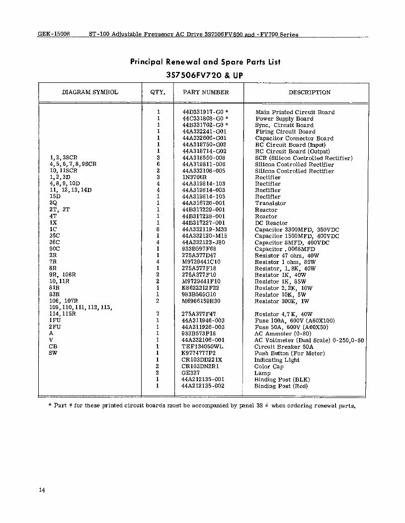
Principal Renewal and Spare Parts List
3S7506FV720 & UP
DIAGRAM SYMBOL QTY. PART NUMBER DESCRIPTION
1,2,3SCR 4,5,6,7,8,9SCR 10,llSCR 1,2,3D 4,8,9, 10D 11, 12,13,14D 15D 2Q 2T, 3T 4T 1x 1c 35c 36C 5oc 2R 7R 8R 9R, 108R 10,llR 81R 83R 106, 107R 109,110,111,112,113, 114,115R 1FU 2FU A V CB SW
1 44D33191’7-GO * Main Printed Circuit Board 1 44C331808-GO * Power Supply Board 1 44B331702-GO * Sync. Circuit Board 1 44A332241-GO1 Firing Circuit Board 1 448332606-GO1 Capacitor Connector Board 1 44A318750-GO2 RC Circuit Board (Input) 1 44A318714-GO2 RC Circuit Board (Output) 3 44A318550-008 SCR (Silicon Controlled Rectifier) 6 44A319811-006 Silicon Controlled Rectifier 2 44A332 108-005 Silicon Controlled Rectifier 3 lN3766R Rectifier 4 448319814-103 Rectifier 4 44A319814-003 Rectifier 1 44A319814-105 Rectifier 1 44A316726-001 Transistor 1 44B317229-001 Reactor
44B317228-001 Reactor : 44B317227-001 DC Reactor 8 44A332119-M33 Capacitor 3300MFD, 350VDC 1 44A332120-Ml5 Capacitor 1500MFD, 400VDC 4 44A332123-J80 Capacitor &MFD, 400VDC 1 933B597F68 Capacitor .0068MFD 1 275A377D47 Resistor 47 ohm, 40W 4 M9729441ClO Resistor 1 ohm, 85W 1 275A377F18 Resistor, 1.8K, 40W 2 275A377FlO Resistor lK, 40W 2 M9729441FlO Resistor lK, 85W
: K8622212F22 Resistor 2.2K, 1OW 983B565GlO Resistor lOK, 5W
2 M6986159H30 Resistor 300K, 1W
7 275A377F47 Resistor 4.7K, 40W 1 44A311946-003 Fuse lOOA, 600V (A60XlOO) 1 44A311926-003 Fuse 5OA, 600V (A60X50) 1 933B573P18 AC Ammeter (O-80) 1 44A332106-001 AC Voltmeter (Dual Scale) O-250,0-50 1 TEF134050WL Circuit Breaker 50A 1 K9774777P2 Push Button (For Meter) 1 CR103DD22 1X Indicating Light 2 CR103DN2Rl Color Cap 2 GE327 Lamp 1 44A212135-001 Binding Post (BLK) 1 44A212135-002 Binding Post (Red)
* Part # for these printed circuit boards must be accompanied by panel 3s # when ordering renewal parts.
14
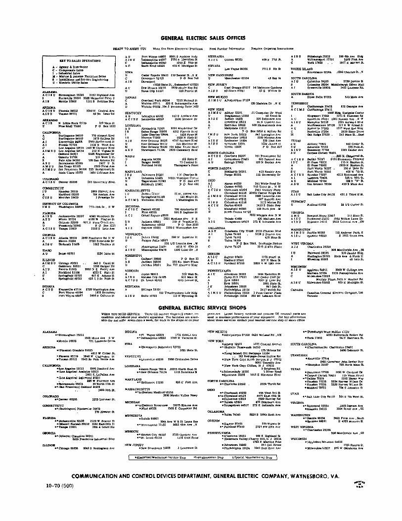
COMMUNICATION AND CONTROL DEVICES DEPARTMENT, GENERAL ELECTRIC COMPANY, WAYNESEORO, VA.
10-70 (500) #“‘-a a:.