
General Construction Notes for the Bock Silage Clamp System
24
General Construction Notes for the Bock Silage Clamp System July 2014
Transcript of General Construction Notes for the Bock Silage Clamp System

General Construction Notes
for the Bock Silage Clamp System
July 2014

CONFIDENTIAL
Contents Typical clamp design .................................................................................................................................................................... 1
Open ended (Drive through) Clamp ....................................................................................................................................... 1 U-shaped Clamp ..................................................................................................................................................................... 1
Environmental Considerations ..................................................................................................................................................... 2
SSAFO Regulations .................................................................................................................................................................. 2 Environment Agency .............................................................................................................................................................. 2 Leachate ................................................................................................................................................................................. 3
Leachate Tanks .................................................................................................................................................................. 3 Leachate Tank Testing ....................................................................................................................................................... 4
Drainage ................................................................................................................................................................................. 4
Durability of Materials ................................................................................................................................................................. 5
Insitu Concrete ....................................................................................................................................................................... 5 Laying the concrete ........................................................................................................................................................... 5 Concrete Curing ................................................................................................................................................................. 5 Surface Treatments ........................................................................................................................................................... 5 Coating thickness and wear............................................................................................................................................... 5
Precast Concrete Panels ......................................................................................................................................................... 6 Hot Rolled Asphalt (HRA) ........................................................................................................................................................ 6
References: ............................................................................................................................................................................. 7
Silo Construction: ......................................................................................................................................................................... 8
1. Frost protection layer .................................................................................................................................................... 8 2. Earth bank construction ................................................................................................................................................ 9 3. Seating channels .......................................................................................................................................................... 10
3.1 Offloading and stacking ..................................................................................................................................... 10 3.2 Installation- General .......................................................................................................................................... 11 3.3 Installation - U shaped clamps ........................................................................................................................... 12
4. Drainage ...................................................................................................................................................................... 12 5. Erection of Precast Walls ............................................................................................................................................. 14
5.1 Offloading wall panels ....................................................................................................................................... 14 5.2 Stacking wall panels ........................................................................................................................................... 14 5.3 Timber struts. .................................................................................................................................................... 15 5.4 Vertical joints ..................................................................................................................................................... 15 5.5 Placing wall panels ............................................................................................................................................. 16 5.6 Fixing of ties ....................................................................................................................................................... 17 5.7 Treatment of horizontal joints ........................................................................................................................... 18 5.8 Backfilling the wall units .................................................................................................................................... 18
6. Silo Floor ...................................................................................................................................................................... 19 7. Silo Wall Leachate protection:..................................................................................................................................... 19
Silo Inspection and Maintenance: .............................................................................................................................................. 20
Wall panels ...................................................................................................................................................................... 20 Silo Floor .......................................................................................................................................................................... 21 Drains .............................................................................................................................................................................. 21 Leachate Tank ................................................................................................................................................................. 21
Disclaimer .................................................................................................................................................................................. 21

Page 1 of 21 CONFIDENTIAL
Typical clamp design Bock UK offers two simple silage clamp designs: -Parallel walls with an opening at both ends (‘Open ended’ or ‘Drive through’ clamps’) being the most common design, or three walls with an opening only at one end (‘U shaped clamps’). Bock UK strongly recommend the open ended layout as this offers more flexibility, ease of operation and better silage quality. ‘U shaped’ clamps should only be considered where site limitations make it impossible to position an open ended clamp. All clamps will be designed in 2.5m increments -standard panel dimensions. For further design advice please contact Bock UK.
Open ended (Drive through) Clamp
U-shaped Clamp

Page 2 of 21 CONFIDENTIAL
Environmental Considerations These Construction Notes have been produced by Bock UK following consultation with the Environment Agency to ensure that silos constructed in this manner should comply with the SSAFO Regulations 2010. SSAFO Regulations
The proposed development will have to meet the requirements of The Water Resources (Control of Pollution) (Silage, Slurry and Agricultural Fuel Oil) Regulations 2010. These are commonly referred to as SSAFO. These SSAFO regulations govern all methods of making and storing of silage crops and set out minimum standards of design and construction, which must be met whenever a relevant system is used. Requirements for silos:-
The system must be impermeable, resistant to corrosion and constructed to meet BS 5502:
Part 22 1993. It must have a life expectancy of at least 20 years (with maintenance).
No part of the system can be within 10 metres of inland freshwaters or coastal waters that
silage Leachate could enter.
The base must have drainage collection channels around the outside. Where there are walls,
the base of the silo must extend beyond them and be designed to collect any Leachate at the
perimeter.
The walls must also be able to withstand any likely load placed upon them in accordance with
BS 5502 Part 22 1993;
Collected Leachate should be conveyed to a purpose-built Leachate tank that should have a
life expectancy of 20 years without maintenance;
All parts of the system must comply with the regulations whenever it is used. Proper
maintenance is therefore essential.
A copy of the regulations can be viewed at: http://archive.defra.gov.uk/environment/quality/water/waterquality/diffuse/nitrate/documents/201009ssafo-england.pdf
Environment Agency
The revised SSAFO regulations came into effect on 15th June 2013.
“(1) This regulation applies to any silo, slurry or fuel oil storage system whose construction is to be begun on or after 15th June 2013 (“a new or improved store”). (2) A person who proposes to have custody or control of silage, slurry or fuel oil that is to be kept in a new or improved store must give the Agency notice specifying the type of silo or storage system and its location, at least 14 days before work constructing the new or improved store is to be begun. (3) In this regulation, “construction” includes substantial enlargement and reconstruction.”
Form WQE3 must be completed for any structure designed to store silage. Form WQE4 must be completed for any silage made and stored in a field clamp and submitted to the EA at least 14 days before the first use of the clamp.

Page 3 of 21 CONFIDENTIAL
The SSAFO regulations do not place requirements on the EA to undertake specific actions when notifications are received, or require them to inspect premises. Upon receipt of the proposals the EA will assess the proposals and may visit the site. The Environment Agency can serve a Notice where there is a significant risk of pollution to controlled waters. They will assess compliance using all appropriate evidence - mainly a visual inspection. The Notice will outline steps to be taken, or for improvements to be made to an existing or to a new installation in order to reduce to a minimum any significant risk of pollution of controlled waters. Normally they will have dialogue with a farmer / operator before serving a Notice. If pollution occurs the farmer / operator may be liable, even if the EA has agreed to the system installed. Leachate
Leachate, (fermentation juice or silage liquor) may occur when preparing, storing or extracting silage. Leachate normally develops during the fermentation process, with dry matter content less than 30%. The majority of leachate will be produced in the first three weeks after the clamp has been filled. Maize silage leachate is highly acidic, pH 4 and has a Biochemical Oxygen Demand BOD of 12,600-90,000mg/litre. The Leachate must be collected, drained off into an impermeable container and disposed of in a safe manner. Collection tanks must be incorporated within the silo system. The drainage system components should be connected with corrosion resistant pipes, of sufficient diameter, located beneath the frost level. The tanks must be monitored and emptied regularly during the drainage period in the first 4 – 6 weeks.
Leachate Tanks Leachate collection tanks buried in the ground must be constructed to meet BS 5502: Part 22 1993, be impermeable and resistant to attack by the highly acidic silage Leachate and must have a life expectancy of at least for 20 years without maintenance. (CIRIA Report 126 provides guidance on tank construction.) The tank size depends upon the Silo System Capacity as indicated in the table below:
Silo Capacity Less than 1,500 m³ Greater than 1,500 m³
Leachate Tank Capacity
20 Litres per m³ Capacity 30m³ + 6.7 Litres for every m³ Capacity over 1,500m³

Page 4 of 21 CONFIDENTIAL
If material with a low dry substance content is ensilaged (e.g. silage maize for biogas,) accumulation of larger amounts of Leachate must be allowed for and daily control of leakage of Leachate during ensilaging is essential.
Outlet or overflows from the Leachate tanks must be within the silo system. The tanks must be emptied regularly such that they are never more than ⅔ full. If regular emptying of the Leachate collection tank cannot be guaranteed, the tank’s capacity must be increased as required. Where a Leachate tank is constructed in situ, below ground or partially below ground, the designer/installer will need to complete the relevant part of EA Form WQE3. Uncontaminated surface water should be drained off outside the silo system to soakaways.
Leachate Tank Testing Before the Leachate tank is backfilled and buried, it must be tested for water tightness. Drainage
During the fermentation process, at least 50% of the silage leachate is generated within the first week and in the next two weeks an additional 25% is produced; thus 75% of the silage leachate can be generated within three weeks after ensiling. Silage leachate can continue to be generated for a period up to eight weeks after ensiling. The graph below shows the pattern of silage leachate generation over time.
It is therefore important to cover the clamps effectively because in cases where rainfall, groundwater or storm water is not excluded, Silage leachate generation can continue for the entire biological life of the silage stack. The Leachate must be drained off quickly to prevent acidic attack at the joint between the silo wall and floor, so in addition to a 2% fall along the axis of the silo, it is recommended that a longitudinal

Page 5 of 21 CONFIDENTIAL
“gulley” is created by sloping the silo floor with a 2% fall away from the side walls. Note that there should be no joints in this gulley. A drainage system is needed for each silo bay which should where possible enable the Leachate and surface water to be drained off separately. This system should be designed by a drainage consultant taking into account the nature of each silage clamp site. Silage residues should be prevented from accumulating on the floor by regular cleaning. The farmer / operator is responsible for the design and operation of the Silage system and they should ensure that pollution of surface or ground waters is prevented.
Durability of Materials Insitu Concrete
Silage Leachate is acidic and attacks all types of concrete, leading to degradation over time. For selection of appropriate concrete mixes for extreme exposure conditions refer to BS8007: 1987, BS 8500-1:2006 and BS8110-1:1997
Laying the concrete Insitu concrete must be ordered to the correct specification and laid with due care. The concrete requires compacting depending on its consistency - compaction may be manual or through mechanical vibration.
Concrete Curing Correct curing ensures that the concrete will achieve maximum strength; have good wear resistance, be durable in terms of resistance to weathering and resistance to chemical corrosion, reduces shrinkage cracking and ensures good adhesion for subsequent silo coatings.
Curing involves retention of moisture in the concrete and the maintenance of a favourable temperature to prolong the hydration process. The curing regime should prevent the development of high temperature gradients within the concrete. Commonly used curing methods include covering the concrete with cover sheets which should be in place for at least 7 days or the application of suitable liquid curing membranes.
Surface Treatments Surface treatments, either as surface coatings or penetrating sealants, should be applied to concrete exposed to strong chemical corrosion (pH < 5.5).
Coating thickness and wear The durability and resistance of surface coatings is largely determined by the strength and quality of the subsurface which is dependent upon proper curing of the concrete.
A sufficient coating thickness (2 or 3 coats) must be achieved; if the coating layers are too thin, acid
penetration may occur, which usually causes even greater damage to the concrete surfaces than if
they had been left untreated. The coating manufacturer's instructions should be followed.

Page 6 of 21 CONFIDENTIAL
Please contact Bock UK for more information on the products we are able to supply to coat panels.
Precast Concrete Panels The concrete used in the Wall Panels is designated C40/50, complying with BS8500 exposure classifications XC4, XF4 and XA3; using 20mm flint aggregate.
Exposure Class
Class Description
Nominal cover to
reinforcement 35+∆cdev
Min Compressive
Strength Class
Min Water/Cement
ratio
Minimum Cement content kg/m
3
XC4 Moderate humidity or cyclical wet and dry 40mm C25/30 0.65 320
XF4 High water saturation 40mm C40/50 0.45 360
XA3 Chemical attack: Acid water PH≤ 4.0 C35/45 0.45 360
An acrylic resin curing membrane is applied to the exposed surface of the panels immediately after casting. The resultant film retains sufficient moisture in the concrete to ensure full hydration of the cement; essential for optimum strength development and durability. The cured concrete is typically harder and exhibits a dust free surface with a reduced incidence of drying shrinkage cracks. The curing membrane also acts as a primer for many subsequent surface treatments that do not rely on penetration for substrate bond. Surface treatments, either as surface coatings or penetrating sealants, should be applied to the wall units after 1 year to give protection against silage Leachate attack. Alternatively protective membranes may be used.
Hot Rolled Asphalt (HRA) Floors of bunker silos are constantly exposed aggressive silage Leachate and mechanical stress due to the use of machinery such as silage cutters, mixing vehicles etc. Asphalt is well suited for the construction of silo floors provided that Limestone materials are excluded. Asphalt is acid-proof, sufficiently resistant to abrasion and withstands mechanical stress. Because of the bitumen’s chemical stability against many acids and Leachates (even in high concentrations,) asphalt achieves a very long useful life provided that the aggregates are added with due care and to the correct formulation. The higher the density of the asphalt laid, the greater its resistance to aggressive fluids; proven construction methods include tightly roller-compacted asphalt or mastic. Bitumen has not been found to contain any harmful or soluble substances that can be expected to have negative effects on food or forage.

Page 7 of 21 CONFIDENTIAL
Asphalt is also used for hygienically demanding circumstances, such as for making drinking water pools, water reservoirs, pipelines etc. watertight. The life of the laid asphalt can be enhanced by ensuring:
- That the area is not used for storage or parking of vehicles, machinery etc. when the clamps is empty.
- Oil, mud and waste silage is removed from the surface as soon as possible. - Any damage to the surface is repaired using a suitable impermeable bitumen product. - All joints between the floor and wall panels and drains are inspected regularly for signs of
wear.
References: CIRIA R126 “Farm Waste Storage: guidelines for construction”
BS5502-2: 1990 “Buildings and structures for agriculture - Code of practice for selection and use of construction materials”
BS8077: 1987 “Design of concrete structures for retaining aqueous liquids”
BS8110-1: 1997 “Structural use of Concrete- code of practice for design and construction”
BS8500-1: 2006 “Concrete – Method of specifying and guidance for the specifier”
ADAS CGN 012 “The use of hot rolled asphalt (HRA) surfacing for agricultural forage silos”
BS 594-1&2:2005 “Hot rolled asphalt for roads and other paved areas”
BS EN 13108-4: 2006 “Bituminous mixtures - Material Specifications - Part 4: Hot Rolled Asphalt”

Page 8 of 21 CONFIDENTIAL
Silo Construction: For health and safety reasons it is recommended to construct the Silo in the following sequence:
1. Frost Protection Layer 2. Earth Bank Construction 3. Laying the seating channel 4. Drainage 5. Placing the wall panels and fitting tension anchors 6. Back-filling the wall panels 7. Laying the silo floor area with asphalt
Section through internal bank
1. Frost protection layer
Frost sensitive soils such as clay or silt can heave when subjected to long periods of sub-zero temperatures. Therefore it may be necessary to replace the frost susceptible soil with a frost-proof base, (e.g. finely graded gravel, sands or other frost-proof soil material,) which can be easily compacted to provide a strong foundation layer. In the case of non-load bearing soil, soil-improvement work will have to be carried out.
Section through Silo Base

Page 9 of 21 CONFIDENTIAL
2. Earth bank construction
It is recommended to first construct a generously dimensioned preliminary earth bank and to then cut it off to match the 23° incline of the wall panel using a digger. The earth bank should be at least 1.45m wide at the top, (1.00m between the tops of the precast wall units) – this is suitable for 15T silage compacting machines. Heavier silage compactors will require wider banks – consult your Structural Engineer.
The bank should be built up in compacted layers – the depth of the layers will depend on the soil, type of machinery being used and local conditions. Allowance must be made for the 250 – 300mm thickness of backfill between the bank and the precast wall units.
A profile frame can be made up as above to achieve the correct bank slope
1.00m

Page 10 of 21 CONFIDENTIAL
The outer slope of external bank should be less than 45˚ for safety reasons; this bank should be planted to prevent soil erosion. A geotextile liner (e.g. Terram T1000) should be placed over the bank, to ensure that the gravel infill does not migrate into the bank.
3. Seating channels
3.1 Offloading and stacking 5m long Seating channels weigh 0.53 T. The seating channels are to be lifted with chains using 2No. M12 lifting loops inserted into sockets cast into the top of the units. Extreme care should be taken when moving and stacking the seating channels to avoid damage. Stacking should be on firm level ground.
Lifting
A set of M12 wire lifting loops (SWL 500kg)
will be supplied with the first delivery of seating channels. These loops screw into the open sockets on the seating channels for easy handling with lifting chains.
Seating channels should not be lifted in the middle with forks.
Stacking
Stacking should be on level ground with bearers placed at
1/5th points
Bearers should line up vertically above one another

Page 11 of 21 CONFIDENTIAL
3.2 Installation- General The seating channel has 2 recesses, the upper (front) recess supports the wall panels, and the lower (back) recess acts as a drain should leachate penetrate the wall. The seating channels are set below the surface of the silo floor so that the flooring material covers the top of the channel. The seating channel must be positioned at a constant offset from the base of the bank to allow placement of the gravel backfill. The seating channels are placed on concrete blinding and anchored against sideways displacement by 2No. H25 bars 600mm long embedded in the lean-mix concrete blinding; (these bars will be supplied with the first plinth delivery.) 2 standard lengths are provided: SC1 (-5m long) and SC5 (-1.25m long). The 1.25m long seating channels are positioned at each end of the run, SC4 channels with cast-in vertical drainage pipes are placed at the lower end of the clamp. Starting with the shorter length ensures that the joints between the seating channels do not coincide with the joints between the 2.5m wide wall units. Each end face of the Seating Channels needs to be treated with a primer before applying the bitumen sealant in accordance with the manufacturer’s instructions. The channel is then pushed up to the next, ensuring that the joint is fully filled, to prevent Leachate leakage.
Bitumen bead sealing joint between seating channels
Wall support Drainage Channel

Page 12 of 21 CONFIDENTIAL
3.3 Installation - U shaped clamps When constructing a ‘U shaped clamp’, separate corner pieces (SC2 and SC2A - see diagram) will be supplied. The seating channels should be laid, working away from the top left corner
4. Drainage
All drainage arrangements are site specific and must adhere to the SSAFO regulations- professional advice from a Drainage engineer should be obtained before work commences. Bock UK does not accept any responsibility for the specific drainage design of the silage clamp, however it is good practice to slope the floor away from the base of the walls and to have a 2% longitudinal fall along the axis of the silo. In the unlikely event of leakage occurring through the vertical joints in the concrete panels, the leachate will percolate down the back of the walls and be intercepted by the Leachate leakage collection drains incorporated in the seating channels. These channels should be connected to an inspection chamber prior to entering the main leachate drainage system. When the highly nutritious silage effluent is used to feed Micro-organisms present in AD plants and suitable control mechanisms must be incorporated by the drainage designer.
Start Here
Lay in this direction
SC2 SC1’s SC2A
SC5 SC5A SC1’s SC1’s SC4 SC4A

Page 13 of 21 CONFIDENTIAL
Surface water collection drains can be located on top of the earth bank, separated fron the free draining backfill by an impermeable membrane to convey rainwater runoff from the silo covers to the surface water drains.
Although there is little likelihood of Leachate leakage through the wall panel joints, the concrete seating channel incorporates a collection drain, thus complying with the SSAFO regulations which require Leachate drains behind the walls. These channels are connected to collection drains which pass through an inspection chamber that is regularly inspected for signs of Leachate contamination.
All drainage pipes should be of sufficient diameter to cater for the volumes generated. These pipes must be surrounded by a jacket of filter gravel which must be separated from the surrounding soil by a geotextile.
The percolation performance of the soakaways should be verified by percolation tests.
Note:
The farmer / operator is responsible for the design and operation of the Silage system and they should ensure that pollution of surface or ground waters is prevented.
If pollution occurs the farmer / operator may be prosecuted by the Environment Agency.
Cross Section through Internal Bank Laying impermeable membrane
Seating Channel with Drain outlet
Page 14 of 21 CONFIDENTIAL
5. Erection of Precast Walls
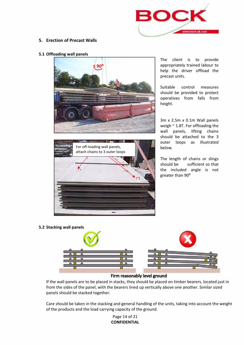
5.1 Offloading wall panels
The client is to provide appropriately trained labour to help the driver offload the precast units. Suitable control measures should be provided to protect operatives from falls from height. 3m x 2.5m x 0.1m Wall panels weigh ~ 1.8T. For offloading the wall panels, lifting chains should be attached to the 3 outer loops as illustrated below. The length of chains or slings should be sufficient so that the included angle is not greater than 90⁰
5.2 Stacking wall panels
If the wall panels are to be placed in stacks, they should be placed on timber bearers, located just in from the sides of the panel, with the bearers lined up vertically above one another. Similar sized panels should be stacked together. Care should be taken in the stacking and general handling of the units, taking into account the weight of the products and the load carrying capacity of the ground.
For off-loading wall panels, attach chains to 3 outer loops
≤ 90⁰

Page 15 of 21 CONFIDENTIAL
5.3 Timber struts. Suitable wooden posts (e.g. 75mm x 75mm x 1.2m long,) provided by the Client, are driven into the bank, one post per wall panel. (These timbers will remain in position after the panels have been backfilled.) The purpose of the posts is to act as temporary support to the wall panels, ensuring that they are correctly aligned at 23⁰ to the vertical and positioned off the bank, before the backfill is placed. Using the profiling gauge, the posts are marked and cut to the correct length to support the wall panels.
5.4 Vertical joints The joints between the wall panels are only subjected to short term exposure to dilute Leachate when the silage is wet. The “halving joints” on each vertical edge need to be treated with a primer and then a bitumen sealant (approx. 0.7 litres / metre run) in accordance with the manufacturer’s instructions, as the walls are erected, to prevent Leachate leakage.
Correct application: Applying plenty of bitumen over entire face ensures the joint is filled
Incorrect application: Insufficient bitumen (note the unsealed gaps between panels)

Page 16 of 21 CONFIDENTIAL
5.5 Placing wall panels
Open ended (Drive through) Clamp U-shaped Clamp
The 1.8T wall panels are lifted from the stack using the two outer loops cast into the back of the unit. The length of chains or slings should be sufficient so that the included angle is not greater than 90⁰
The wall panels are lowered into the upper groove in the seating channel and leant against the wooden strut.
≤ 90⁰
Start Here
Lay in this direction
PC11 PC1’s PC10 PC9A PC9 PC1A’s PC1’s PC5A PC5 PC6A PC6 PC7A PC7
SC1’s SC1’s SC4 SC4A
PC4 PC4A PC3 PC3A PC2 PC2A PC1’s PCA1’s PC5 PC5A PC6 PC6A PC7 PC7A
Start this End
Slo
pin
g p
anel
s
S
lop
ing
pan
els
Slo
pin
g p
anel
s
S
lop
ing
pan
els
Slo
pin
g p
anel
s
Slo
pin
g p
anel
s
Lay
in t
his
dir
ect
ion
Lay
in t
his
dir
ect
ion

Page 17 of 21 CONFIDENTIAL
It is suggested that pieces of wood are used as wedges to keep the bottom of the panel tight against the back of the precast seating channel.
An 800mm long tube is placed through the top loops at the sides of the wall unit and secured with a wedge to ensure that there is a tight joint between the units.
The Seating Channel lifting eyes (SWL= 0.5T) should not be attached to the sockets cast in the top of the panels which are only designed to support the handrail or SiloClip system. Bock UK will provide you with drawings outlining the correct layout of the wall panels and channels for the clamp design.
5.6 Fixing of ties The tension ties are designed to restrain the wall panels from being displaced when the gravel backfill is placed.
For internal banks, the wall panels are tied to one another by hooking the ends of the 1.2m threaded tie bars through the centre loop cast in the back of the wall panel, (500mm from the
top,) and fixing them together with a drilled plate and nuts. (Tension ties can be omitted for joining lower sloping panels PC3,PC4, PC6 and PC7.) For external wall panels, the hooked end of the 1.20m long tie bar is inserted through the centre loop cast into the back of the panel and the anchor plate is fixed to the other end and laid on the top of the bank. A U bar, placed tight against the anchor plate is driven vertically into the bank to restrain the assembly.
2 No. 16mm threaded ties pass through plate and secured with nuts

Page 18 of 21 CONFIDENTIAL
5.7 Treatment of horizontal joints
The gap between the top of the plinth and the precast walls is filled with non-shrink grout and the wooden wedges removed. This joint will be covered by the asphalt support layer.
5.8 Backfilling the wall units Free draining backfilling material (8–32mm) should be carefully trickled into the 250 – 300mm gap behind the precast walls in 150mm layers. Recycled concrete as produced at state-of-the-art reprocessing plants is also suitable; to assess the material the constructor must consult a specialist (e.g. a civil engineer or a road construction specialist). The drainage material should not be mechanically compacted or washed in.
1 No. hooked threaded bar, 1 No. plate, 2 No. nuts and washers; plate restrained by 1No. U bar driven vertically into bank

Page 19 of 21 CONFIDENTIAL
6. Silo Floor
Hot Rolled Asphalt (HRA) should be laid in two layers with the void content limited to a maximum of 3.0% vol. Careful compacting is therefore required, especially towards the margins. The mineral products used (e.g. grit, sand and filler) must be resistant to acids, e.g. basalt, granite etc. - Limestone fillers must not be used. The recommendations made in this document only apply to the use of roller-compacted asphalt. Large areas of asphalt are laid by machine, smaller areas by hand. It is particularly important to avoid unevenness which leads to puddle formation, and ensure careful compaction to avoid subsequent Leachate infiltration through the asphalt layer. It is normal practice to offset joints in different layers. Careful planning of this operation is essential as the asphalt should be laid in a continuous operation. (Cold asphalt is difficult to compact and does not produce a smooth surface.) The gap between the top of the silo floor and the precast walls is to be filled with an acid resistant, permanently elastic bitumen material or epoxy sealant. Newly laid HRA should not be trafficked until it has cooled to ambient temperatures - normally about 24 hours. Certain machinery oils soften HRA and sustained point loadings can damage the surface. HRA surfaces should not be used as permanent parking or for pallet/feed trough storage areas.
7. Silo Wall Leachate protection: Leachate is acidic and attacks all types of concrete, leading to degradation over time. Surface treatments, either as surface coatings or penetrating sealants, should be applied to the wall units after 1 year to give protection against Leachate attack. Protective membranes such as Bock polyethylene Silo Wall Film should be used to ensure that air is kept out of the silage and to protect the concrete walls. This film remains on top of the side walls while the silo is filled.

Page 20 of 21 CONFIDENTIAL
Silo Inspection and Maintenance: Element Symptom Cause Remedy Walls Cracked or spalled concrete Machinery impact damage
causing corrosion of reinforcement due to insufficient concrete cover
Remove damaged concrete and make good with Bock 2-part Silo Epoxy Resin.
Erosion of concrete Leachate dissolving cement matrix
Repair damaged area with Bock 2-part Silo Epoxy Resin. Bock Protective Silo Paint can be applied to the bottom of the wall panels. Alternatively protective membranes such as Bock polyethylene Silo Wall Film can be used.
Wall Joints
Leachate detected in inspection chamber. Sealant between concrete wall panels damaged or degraded
Inappropriate sealant or simply worn out
Remove old jointing material. Clean out joint and reseal vertical joints between the precast wall panels with Bock Bitumen filler.
Floor Floor eroded Leachate dissolving cement matrix
If only slight erosion, slow down further deterioration by coating with penetrating sealer. If severe erosion, resurface
Floor Joints
Leachate detected in inspection chamber. Sealant between Floor / Wall panels damaged or degraded
Inappropriate sealant, or simply worn out
Remove old jointing material. Reform groove. Reseal with permanently elastic, acid-proof bitumen grouting compound.
Wall panels Before the silo is filled the wall panels, joints and asphalt should be inspected for damage and repairs carried out as necessary. Wall panels should be thoroughly cleaned to remove old silage residue. Repairs can be made using Bock 2-part Silo Epoxy Resin. Bock Silo mould protection coating can be sprayed onto the concrete and Bock Protective Silo Paint can be applied to the bottom of the wall panels. Vertical joints between the precast wall panels should be repaired with Bock Bitumen filler.

Page 21 of 21 CONFIDENTIAL
The horizontal joint between the wall panel and silo base should also be inspected and repaired as necessary with permanently elastic, acid-proof bitumen grouting compound.
Silo Floor Silage residues should be prevented from accumulating on the floor by regular cleaning. Repair: Where small areas of the surface are damaged propriety bituminous products are available; these should be checked for their permeability characteristics. They must be used strictly in accordance with the manufacturer’s instructions and be inert after curing. For major repairs consult an experienced contractor. Resurfacing: A detailed survey of the existing floor slab should be carried out to confirm that a new surface could be laid without causing any structural damage. Once the base is approved as structurally sound the old floor should be prepared in the following manner:
a. Power wash apron to create a clean surface.
b. Thoroughly clean all existing cracks or open joints and fill with a sealant.
c. Repair potholes and failed edges.
d. Form chases in floor at the front of clamp to key the new surface.
e. Apply tack coat.
f. Lay and compact HRA surface course and caulk joints with sealants or water bars.
Drains The Leachate inspection chamber should be inspected regularly to ensure that there is no leakage through the concrete walls / joints. If Leachate leakage is detected the wall panels and joints will need to be inspected and repaired.
Leachate Tank Tanks must be monitored and emptied regularly during the drainage period in the first 4 – 6 weeks. The tanks must be emptied regularly such that they are never more than ⅔ full.
Disclaimer
Bock UK Limited assumes no liability for damages caused by incorrect construction of the silo. The work described must be performed by qualified specialist firm. - The selection of such specialist firms is at the sole discretion of the client. Bock UK Ltd Milbank House Earls Colne Business Park Colchester, Essex. CO6 2NS
Note: These construction specifications are not to be disclosed to third parties!

u7618777
Snapshot
u7618777
Text Box
Storage Facility Profile