General Commands Reference Guide F - Lauterbach · General Commands Reference Guide F 1 ©1989-2017...
131
General Commands Reference Guide F 1 ©1989-2018 Lauterbach GmbH General Commands Reference Guide F TRACE32 Online Help TRACE32 Directory TRACE32 Index TRACE32 Documents ...................................................................................................................... General Commands ...................................................................................................................... General Commands Reference Guide F ................................................................................... 1 History ...................................................................................................................................... 7 FDX ........................................................................................................................................... 8 FDX tbd. 8 Trace Method FDX 8 FDX-specific Trace Command ............................................................................................... 9 FDX.METHOD Select communication channel 9 Generic FDX Commands ........................................................................................................ 11 FDX.Arm Arm the trace 11 FDX.AutoArm Arm automatically 11 FDX.AutoFocus Calibrate AUTOFOCUS preprocessor 11 FDX.AutoInit Automatic initialization 11 FDX.AutoTEST Continuous measurement 11 FDX.BookMark Set a bookmark in trace listing 11 FDX.Chart Display trace contents graphically 12 FDX.Chart.DistriB Distribution display 12 FDX.Chart.Func Function activity chart 12 FDX.Chart.GROUP Group activity chart 12 FDX.Chart.Line Graphical HLL lines analysis 12 FDX.Chart.sYmbol Symbol analysis 12 FDX.Chart.TASK Task activity chart 12 FDX.Chart.TASKFunc Task related function run-time analysis (legacy) 13 FDX.Chart.TASKSRV Service routine run-time analysis 13 FDX.Chart.TASKState Task state analysis 13 FDX.Chart.VarState Variable activity chart 13 FDX.CLEAR Clear FDX communication buffers 13 FDX.CLOSE Close FDX files 13 FDX.ComPare Compare trace contents 13 FDX.DISable Disable the trace 14 FDX.DISableChannel Disable FDX communication 14 FDX.DRAW Visualization of trace data 14 FDX.ENableChannel Enable FDX communication 14
Transcript of General Commands Reference Guide F - Lauterbach · General Commands Reference Guide F 1 ©1989-2017...

General Commands Reference Guide F
TRACE32 Online Help
TRACE32 Directory
TRACE32 Index
TRACE32 Documents ......................................................................................................................
General Commands ......................................................................................................................
General Commands Reference Guide F ................................................................................... 1
History ...................................................................................................................................... 7
FDX ........................................................................................................................................... 8
FDX tbd. 8
Trace Method FDX 8
FDX-specific Trace Command ............................................................................................... 9
FDX.METHOD Select communication channel 9
Generic FDX Commands ........................................................................................................ 11
FDX.Arm Arm the trace 11
FDX.AutoArm Arm automatically 11
FDX.AutoFocus Calibrate AUTOFOCUS preprocessor 11
FDX.AutoInit Automatic initialization 11
FDX.AutoTEST Continuous measurement 11
FDX.BookMark Set a bookmark in trace listing 11
FDX.Chart Display trace contents graphically 12
FDX.Chart.DistriB Distribution display 12
FDX.Chart.Func Function activity chart 12
FDX.Chart.GROUP Group activity chart 12
FDX.Chart.Line Graphical HLL lines analysis 12
FDX.Chart.sYmbol Symbol analysis 12
FDX.Chart.TASK Task activity chart 12
FDX.Chart.TASKFunc Task related function run-time analysis (legacy) 13
FDX.Chart.TASKSRV Service routine run-time analysis 13
FDX.Chart.TASKState Task state analysis 13
FDX.Chart.VarState Variable activity chart 13
FDX.CLEAR Clear FDX communication buffers 13
FDX.CLOSE Close FDX files 13
FDX.ComPare Compare trace contents 13
FDX.DISable Disable the trace 14
FDX.DISableChannel Disable FDX communication 14
FDX.DRAW Visualization of trace data 14
FDX.ENableChannel Enable FDX communication 14
General Commands Reference Guide F 1 ©1989-2018 Lauterbach GmbH

FDX.EXPORT Export trace data for processing in other applications 14
FDX.FILE Load a file into the file trace buffer 14
FDX.Find Find specified entry in trace 14
FDX.FindAll Find all specified entries in trace 14
FDX.FindChange Search for changes in trace flow 15
FDX.GOTO Move cursor to specified trace record 15
FDX.InChannel Inchannel state display 15
FDX.Init Initialize trace 15
FDX.List List trace contents 15
FDX.ListNesting Analyze function nesting 15
FDX.ListVar List variable recorded to trace 15
FDX.LOAD Load trace file for offline processing 15
FDX.Mode Set the trace operation mode 16
FDX.OFF Switch off 16
FDX.Out tbd. 16
FDX.PROfileChart Profile charts 16
FDX.PROfileChart.DIStance Time interval for a single event 16
FDX.PROfileChart.DURation Time between two events 16
FDX.PROfileChart.GROUP Group profile chart 16
FDX.PROfileChart.Rate Event frequency 17
FDX.PROTOcol.Chart Graphic display for user-defined protocol 17
FDX.PROTOcol.Draw Graphic display for user-defined protocol 17
FDX.PROTOcol.EXPORT Export trace buffer for user-defined protocol 17
FDX.PROTOcol.Find Find in trace buffer for user-defined protocol 17
FDX.PROTOcol.List Display trace buffer for user-defined protocol 17
FDX.PROTOcol.STATistic Display statistics for user-defined protocol 17
FDX.Rate Select sampling rate 18
FDX.REF Set reference point for time measurement 18
FDX.RESet Reset command 18
FDX.SAVE Save trace for postprocessing in TRACE32 18
FDX.SelfArm Automatic restart of trace recording 18
FDX.SIZE Define buffer size 18
FDX.SnapShot Restart trace capturing once 18
FDX.state Display trace configuration window 18
FDX.STATistic Statistic analysis 19
FDX.STATistic.DIStance Time interval for a single event 19
FDX.STATistic.DistriB Distribution analysis 19
FDX.STATistic.DURation Time between two events 19
FDX.STATistic.Func Nesting function runtime analysis 19
FDX.STATistic.GROUP Group run-time analysis 19
FDX.STATistic.Ignore Ignore false records in statistic 19
FDX.STATistic.InterruptIsFunction Statistics interrupt processing 20
FDX.STATistic.Line HLL-line analysis 20
General Commands Reference Guide F 2 ©1989-2018 Lauterbach GmbH

FDX.STATistic.LINKage Per caller statistic of function 20
FDX.STATistic.Measure Analyze the performance of a single signal 20
FDX.STATistic.PreFetch Prefetch detection 20
FDX.STATistic.Sort Specify sorting criterion for statistic commands 20
FDX.STATistic.sYmbol Flat run-time analysis 20
FDX.STATistic.TASK Task activity statistic 21
FDX.STATistic.TASKFunc Task specific function run-time analysis 21
FDX.STATistic.TASKKernel Task analysis with kernel markers (flat) 21
FDX.STATistic.TASKSRV Analysis of time in OS service routines 21
FDX.STATistic.TASKState Performance analysis 21
FDX.STATistic.TASKTREE Tree display of task specific functions 21
FDX.STATistic.TREE Tree display of nesting function run-time analysis 21
FDX.STATistic.Use Use records 22
FDX.TimeStamp Configure timestamp usage of LOGGER trace 22
FDX.Timing Waveform of trace buffer 22
FDX.TraceChannel tbd. 22
FDX.TRACK Set tracking record 22
FDX.View Display single record 22
FDX.ZERO Align timestamps of trace and timing analyzers 22
FIFO .......................................................................................................................................... 23
FIFO Display on-chip trace FIFO 23
FLAG ......................................................................................................................................... 24
FLAG Flag system of ICE and FIRE 24
Overview FLAG 24
Flag System of TRACE32-ICE 24
Applications 25
Problems 25
Flag System of TRACE32-FIRE 26
Applications 26
Problems 26
FLAG.Delete Delete flags 26
FLAG.Init Initialization 27
FLAG.List Display flags 27
FLAG.ListFunc Code-coverage functions 28
FLAG.ListModul Code-coverage modules 31
FLAG.ListVar Code-coverage variables 33
FLAG.OFF Switch off flag system 35
FLAG.ON Switch on flag system 36
FLAG.RESet Reset 36
FLAG.Set Set 36
FLAG.SetSec Mark sections 37
FLAG.state State 37
General Commands Reference Guide F 3 ©1989-2018 Lauterbach GmbH

FLASH ...................................................................................................................................... 39
FLASH External FLASH memories and on-chip FLASH memories 39
Overview FLASH 39
FLASH.AUTO Auto programming of FLASH 40
FLASH.BSDLaccess Enables FLASH access via boundary scan 41
FLASH.CFI Generate FLASH declaration by CFI 42
FLASH.CHANGEtype Changes the FLASH type 46
FLASH.CLocK Setup input clock for processor internal flash 47
FLASH.Create Declare FLASH 48
FLASH.CreateALIAS Create address alias 53
FLASH.Delete Delete entry in FLASH declaration table 54
FLASH.Erase Erase FLASH 55
FLASH.HOOKSCRIPT PRACTICE script based FLASH programming prolog 55
FLASH.List Display FLASH definition table 57
FLASH.LOCK Lock FLASH 58
FLASH.MultiProgram Simultaneous programming of flash sectors 59
FLASH.OFFSET Change FLASH control address 59
FLASH.Program Program FLASH 60
FLASH.ReProgram Re-program FLASH 61
FLASH.RESet Reset FLASH declaration table 62
FLASH.SPICMD Send data to SPI FLASH device 63
FLASH.state FLASH programming dialog 65
FLASH.TARGET Define target controlled algorithm 66
FLASH.TARGET2 Define second target controlled algorithm 73
FLASH.UNLOCK Unlock FLASH 74
FLASH.UNSECUREerase Unsecure a device 76
FLASHFILE ............................................................................................................................... 77
FLASHFILE NAND flash and serial flash devices 77
FLASHFILE.BSDLaccess Enables FLASH access via boundary scan 77
FLASHFILE.BSDLFLASHTYPE Define FLASH type 78
FLASHFILE.CONFIG Configure FLASH 78
FLASHFILE.COPY Copy to FLASH 79
FLASHFILE.COPYSPARE Copy to spare area of NAND FLASH 80
FLASHFILE.Create Declaration of flash memories: create a block/sector 81
FLASHFILE.DUMP Dump FLASH 82
FLASHFILE.Erase Erase FLASH 83
FLASHFILE.GETBADBLOCK Get the bad block addresses 84
FLASHFILE.GETEXTCSD Get the extended CSD register 84
FLASHFILE.GETID Get ID 85
FLASHFILE.GETONFI Display ONFI 85
FLASHFILE.List List blocks or sectors of FLASH memory 86
FLASHFILE.LOAD Load files to FLASH 87
FLASHFILE.LOAD.binary Write FLASH 87
General Commands Reference Guide F 4 ©1989-2018 Lauterbach GmbH

FLASHFILE.LOAD.Elf Load ELF file 90
FLASHFILE.LOAD.IntelHex Load Intel hex file 90
FLASHFILE.LOAD.Srecord Load an 'Srecord' file 91
FLASHFILE.LOADALL Load to main area and spare area 91
FLASHFILE.LOADECC Load ECC file to spare area 92
FLASHFILE.LOADSPARE Write NAND FLASH spare area 94
FLASHFILE.LOCK Lock the FLASH device 94
FLASHFILE.MSYSDLL Access an M-Systems DiskOnChip flash device 95
FLASHFILE.RESet Reset FLASH configuration 95
FLASHFILE.SAVE Save FLASH 96
FLASHFILE.SAVEALL Save the main area and the spare area 96
FLASHFILE.SAVEECC Save error correction code (ECC) to file 97
FLASHFILE.SAVEECC.BCH Save ECC with BCH algorithm 97
FLASHFILE.SAVEECC.hamming Save ECC with Hamming algorithm 100
FLASHFILE.SAVEECC.ReedSolomon Save ECC with Reed-S. algorithm 103
FLASHFILE.SAVESPARE Read NAND FLASH spare area 105
FLASHFILE.Set Modify FLASH data 105
FLASHFILE.SETEXTCSD Modify the extended CSD register 106
FLASHFILE.SPICMD Send data to SPI FLASH device 107
FLASHFILE.state tbd. 109
FLASHFILE.TARGET Define target controlled algorithm 110
FLASHFILE.UNLOCK Unlock FLASH device 111
FPU ........................................................................................................................................... 112
FPU Access to FPU registers 112
FPU.OFF FPU access off 112
FPU.ON FPU access on 113
FPU.RESet Reset command 113
FPU.Set Modify FPU registers 113
FPU.TARGET Define FPU access agent 114
FPU.view Display FPU registers 114
Frame ........................................................................................................................................ 115
Frame Call-tree and context 115
Frame.CONFIG Fine-tune stack unwinding 115
Frame.CONFIG.Asm Frame back-trace mode 115
Frame.CONFIG.EABI Use chained frame pointers 116
Frame.CONFIG.EPILOG Use epilog code for frame display 117
Frame.CONFIG.PROLOG Use prolog code for frame display 117
Frame.CONFIG.RELOAD Generate frame information again 118
Frame.CONFIG.sYmbol Use symbol code for frame display 118
Frame.COPY Copy to TRACE32 registers 119
Frame.Down Go down in stack nesting 119
Frame.GOTO Change source code view temporarily 119
Frame.Init Initialize the processor registers 120
General Commands Reference Guide F 5 ©1989-2018 Lauterbach GmbH

Frame.REDO Recover from UNDO registers 123
Frame.SkipFunc Change view to previous/subsequent function 123
Frame.SkipLine Change view to previous/subsequent HLL line 124
Frame.SWAP Swap TRACE32 registers 124
Frame.TASK Change view to specified task 124
Frame.UNDO Recover previous registers 126
Frame.Up Go up in stack nesting 126
Frame.view Display stack frame 128
FXU ........................................................................................................................................... 130
FXU FXU registers (extended floating point unit) 130
FXU.Init Initialize FXU registers 130
FXU.Set Modify FXU registers 130
FXU.view Open FXU register window 131
Usage:
(B) command only available for ICD(E) command only available for ICE(F) command only available for FIRE
General Commands Reference Guide F 6 ©1989-2018 Lauterbach GmbH

General Commands Reference Guide F
Version 22-Mar-2018
History
30-Jan-18 Description for the commands FLASHFILE.SPICMD and FLASH.SPICMD.
11-Jan-18 Description for the command FLASH.HOOKSCRIPT added.
16-Aug-17 Frame.view command was updated. Options are now differentiated by <display_option> and <context_option>.
18-Jan-17 Added description and example for the new LAYOUT option of the FLASHFILE.SAVEECC.* commands; for details, see FLASHFILE.SAVEECC.hamming. Updated FLASH.CHANGEtype.
18-Nov-16 Added an illustration of the BSPLIT option for the commands FLASH.Create and FLASH.CFI.
General Commands Reference Guide F 7 History ©1989-2018 Lauterbach GmbH

FDX
FDX tbd.
See also
■ <trace>.METHOD
▲ ’FDX-specific Trace Command’ in ’General Commands Reference Guide F’▲ ’Generic FDX Commands’ in ’General Commands Reference Guide F’▲ ’Release Information’ in ’Release History’
Trace Method FDX
The trace method FDX is mainly used for TRACE32-ICD without a trace extension.
Problem description: A TRACE32-ICD debugger is used to test and integrate an application program on the target. Now a problem occurs that could easily be solved if more information about the program history would be available.
Usually a TRACE32-ICD trace extension can be used to get more information about the program history. But not all targets allow the operation of such a trace. For these targets, TRACE32 offers a software trace. The software trace however needs RAM from the target and is influencing the real-time behavior.
To operate a software trace, TRACE32 provides:
• A general trace format for a software trace located in the target RAM.
• Configuration and display commands for the software trace in the TRACE32 software(command group: FDX).
• Predefined algorithms to operate the software trace from the target program.
To use the software trace basic knowledge of the target hardware and the processor architecture is required.
Implementation of the trace memory
The user reserves a part of the target RAM, that can be used for the trace information.
Max. trace size Any desired.
Sampling The trace memory is filled either by an algorithm predefined by LAUTERBACH or by a user-defined algorithm.The algorithm can either be called by an interrupt or the code has to be instrumented.
Influence on the real-time behavior
Yes, how much depends on the implementation of the sampling algorithm.
Selective tracing Possible by the sampling algorithm.
General Commands Reference Guide F 8 FDX ©1989-2018 Lauterbach GmbH

FDX-specific Trace Command
FDX.METHOD Select communication channel
If a <method> is specified, the command defines the low-level communication channel. Without <method>, the command displays the currently selected <method> in the TRACE32 message line.
BufferE and DCC are methods where the CPU does not need to be stopped to transfer data. These modes require a hardware support from the CPU. The BUFFER methods require a buffer at the target side. The host is accessing these buffers by memory access to its addresses.
The DCC channel is a real-time debug communication channel which needs to be supported by the CPU. DCC, DCC3, DCC4D require a 4-byte wide channel. DCC7 and DCC8 require a 8-byte wide channel. BufferC and BufferS require a stopped CPU to transfer data that’s why this methods are very slow compared to the other methods.
Fastest sampling rate
Depends on the sampling algorithm.
Format: FDX.METHOD [<method>]
<method>: BufferE | BufferC | BufferS | DCC3 | DCC | DCC4D | DCC7 | DCC8
BufferE Transfers the data via Dual Port Memory access. This method requires a buffer at the target side and a special CPU feature that allow to read memory while CPU is running
BufferC Transfers the data after the CPU is stopped.
BufferS Transfers the data when the CPU has reached a SPOT breakpoint
DCC3 4-byte wide channel, where the first byte defines if the last 3 bytes are used.
DCC 4-byte wide channel (e.g. ARM family)
DCC4D 4-byte wide channel without FDX high level protocol, every package is 4 byte wide
General Commands Reference Guide F 9 FDX-specific Trace Command ©1989-2018 Lauterbach GmbH

DCC7 8-byte wide channel, where the first byte defines if the last 8 bytes are used.
DCC8 8-byte wide channel
General Commands Reference Guide F 10 FDX-specific Trace Command ©1989-2018 Lauterbach GmbH

Generic FDX Commands
FDX.Arm Arm the trace
See command <trace>.Arm in 'General Commands Reference Guide T' (general_ref_t.pdf, page 108).
FDX.AutoArm Arm automatically
See command <trace>.AutoArm in 'General Commands Reference Guide T' (general_ref_t.pdf, page 109).
FDX.AutoFocus Calibrate AUTOFOCUS preprocessor
See command <trace>.AutoFocus in 'General Commands Reference Guide T' (general_ref_t.pdf, page 109).
FDX.AutoInit Automatic initialization
See command <trace>.AutoInit in 'General Commands Reference Guide T' (general_ref_t.pdf, page 114).
FDX.AutoTEST Continuous measurement
See command <trace>.AutoTEST in 'General Commands Reference Guide T' (general_ref_t.pdf, page 115).
FDX.BookMark Set a bookmark in trace listing
See command <trace>.BookMark in 'General Commands Reference Guide T' (general_ref_t.pdf, page 117).
General Commands Reference Guide F 11 Generic FDX Commands ©1989-2018 Lauterbach GmbH

FDX.Chart Display trace contents graphically
See command <trace>.Chart in 'General Commands Reference Guide T' (general_ref_t.pdf, page 121).
FDX.Chart.DistriB Distribution display
See command <trace>.Chart.DistriB in 'General Commands Reference Guide T' (general_ref_t.pdf, page 132).
FDX.Chart.Func Function activity chart
See command <trace>.Chart.Func in 'General Commands Reference Guide T' (general_ref_t.pdf, page 135).
FDX.Chart.GROUP Group activity chart
See command <trace>.Chart.GROUP in 'General Commands Reference Guide T' (general_ref_t.pdf, page 136).
FDX.Chart.Line Graphical HLL lines analysis
See command <trace>.Chart.Line in 'General Commands Reference Guide T' (general_ref_t.pdf, page 137).
FDX.Chart.sYmbol Symbol analysis
See command <trace>.Chart.sYmbol in 'General Commands Reference Guide T' (general_ref_t.pdf, page 139).
FDX.Chart.TASK Task activity chart
See command <trace>.Chart.TASK in 'General Commands Reference Guide T' (general_ref_t.pdf, page 143).
General Commands Reference Guide F 12 Generic FDX Commands ©1989-2018 Lauterbach GmbH

FDX.Chart.TASKFunc Task related function run-time analysis (legacy)
See command <trace>.Chart.TASKFunc in 'General Commands Reference Guide T' (general_ref_t.pdf, page 144).
FDX.Chart.TASKSRV Service routine run-time analysis
See command <trace>.Chart.TASKSRV in 'General Commands Reference Guide T' (general_ref_t.pdf, page 146).
FDX.Chart.TASKState Task state analysis
See command <trace>.Chart.TASKState in 'General Commands Reference Guide T' (general_ref_t.pdf, page 147).
FDX.Chart.VarState Variable activity chart
See command <trace>.Chart.VarState in 'General Commands Reference Guide T' (general_ref_t.pdf, page 150).
FDX.CLEAR Clear FDX communication buffers
See command <trace>.CLEAR in 'General Commands Reference Guide T' (general_ref_t.pdf, page 153).
FDX.CLOSE Close FDX files
See command <trace>.CLOSE in 'General Commands Reference Guide T' (general_ref_t.pdf, page 154).
FDX.ComPare Compare trace contents
See command <trace>.ComPare in 'General Commands Reference Guide T' (general_ref_t.pdf, page 154).
General Commands Reference Guide F 13 Generic FDX Commands ©1989-2018 Lauterbach GmbH

FDX.DISable Disable the trace
See command <trace>.DISable in 'General Commands Reference Guide T' (general_ref_t.pdf, page 159).
FDX.DISableChannel Disable FDX communication
See command <trace>.DISableChannel in 'General Commands Reference Guide T' (general_ref_t.pdf, page 159).
FDX.DRAW Visualization of trace data
See command <trace>.DRAW in 'General Commands Reference Guide T' (general_ref_t.pdf, page 163).
FDX.ENableChannel Enable FDX communication
See command <trace>.ENableChannel in 'General Commands Reference Guide T' (general_ref_t.pdf, page 186).
FDX.EXPORT Export trace data for processing in other applications
See command <trace>.EXPORT in 'General Commands Reference Guide T' (general_ref_t.pdf, page 187).
FDX.FILE Load a file into the file trace buffer
See command <trace>.FILE in 'General Commands Reference Guide T' (general_ref_t.pdf, page 200).
FDX.Find Find specified entry in trace
See command <trace>.Find in 'General Commands Reference Guide T' (general_ref_t.pdf, page 202).
FDX.FindAll Find all specified entries in trace
See command <trace>.FindAll in 'General Commands Reference Guide T' (general_ref_t.pdf, page 206).
General Commands Reference Guide F 14 Generic FDX Commands ©1989-2018 Lauterbach GmbH

FDX.FindChange Search for changes in trace flow
See command <trace>.FindChange in 'General Commands Reference Guide T' (general_ref_t.pdf, page 207).
FDX.GOTO Move cursor to specified trace record
See command <trace>.GOTO in 'General Commands Reference Guide T' (general_ref_t.pdf, page 211).
FDX.InChannel Inchannel state display
See command <trace>.InChannel in 'General Commands Reference Guide T' (general_ref_t.pdf, page 222).
FDX.Init Initialize trace
See command <trace>.Init in 'General Commands Reference Guide T' (general_ref_t.pdf, page 222).
FDX.List List trace contents
See command <trace>.List in 'General Commands Reference Guide T' (general_ref_t.pdf, page 226).
FDX.ListNesting Analyze function nesting
See command <trace>.ListNesting in 'General Commands Reference Guide T' (general_ref_t.pdf, page 237).
FDX.ListVar List variable recorded to trace
See command <trace>.ListVar in 'General Commands Reference Guide T' (general_ref_t.pdf, page 240).
FDX.LOAD Load trace file for offline processing
See command <trace>.LOAD in 'General Commands Reference Guide T' (general_ref_t.pdf, page 241).
General Commands Reference Guide F 15 Generic FDX Commands ©1989-2018 Lauterbach GmbH

FDX.Mode Set the trace operation mode
See command <trace>.Mode in 'General Commands Reference Guide T' (general_ref_t.pdf, page 246).
FDX.OFF Switch off
See command <trace>.OFF in 'General Commands Reference Guide T' (general_ref_t.pdf, page 250).
FDX.Out tbd.
See command <trace>.Out in 'General Commands Reference Guide T' (general_ref_t.pdf, page 250).
FDX.PROfileChart Profile charts
See command <trace>.PROfileChart in 'General Commands Reference Guide T' (general_ref_t.pdf, page 258).
FDX.PROfileChart.DIStance Time interval for a single event
See command <trace>.PROfileChart.DIStance in 'General Commands Reference Guide T' (general_ref_t.pdf, page 259).
FDX.PROfileChart.DURation Time between two events
See command <trace>.PROfileChart.DURation in 'General Commands Reference Guide T' (general_ref_t.pdf, page 260).
FDX.PROfileChart.GROUP Group profile chart
See command <trace>.PROfileChart.GROUP in 'General Commands Reference Guide T' (general_ref_t.pdf, page 265).
General Commands Reference Guide F 16 Generic FDX Commands ©1989-2018 Lauterbach GmbH

FDX.PROfileChart.Rate Event frequency
See command <trace>.PROfileChart.Rate in 'General Commands Reference Guide T' (general_ref_t.pdf, page 266).
FDX.PROTOcol.Chart Graphic display for user-defined protocol
See command <trace>.PROTOcol.Chart in 'General Commands Reference Guide T' (general_ref_t.pdf, page 276).
FDX.PROTOcol.Draw Graphic display for user-defined protocol
See command <trace>.PROTOcol.Draw in 'General Commands Reference Guide T' (general_ref_t.pdf, page 278).
FDX.PROTOcol.EXPORT Export trace buffer for user-defined protocol
See command <trace>.PROTOcol.EXPORT in 'General Commands Reference Guide T' (general_ref_t.pdf, page 279).
FDX.PROTOcol.Find Find in trace buffer for user-defined protocol
See command <trace>.PROTOcol.Find in 'General Commands Reference Guide T' (general_ref_t.pdf, page 280).
FDX.PROTOcol.List Display trace buffer for user-defined protocol
See command <trace>.PROTOcol.List in 'General Commands Reference Guide T' (general_ref_t.pdf, page 281).
FDX.PROTOcol.STATistic Display statistics for user-defined protocol
See command <trace>.PROTOcol.STATistic in 'General Commands Reference Guide T' (general_ref_t.pdf, page 284).
General Commands Reference Guide F 17 Generic FDX Commands ©1989-2018 Lauterbach GmbH

FDX.Rate Select sampling rate
See command <trace>.Rate in 'General Commands Reference Guide T' (general_ref_t.pdf, page 289).
FDX.REF Set reference point for time measurement
See command <trace>.REF in 'General Commands Reference Guide T' (general_ref_t.pdf, page 290).
FDX.RESet Reset command
See command <trace>.RESet in 'General Commands Reference Guide T' (general_ref_t.pdf, page 291).
FDX.SAVE Save trace for postprocessing in TRACE32
See command <trace>.SAVE in 'General Commands Reference Guide T' (general_ref_t.pdf, page 293).
FDX.SelfArm Automatic restart of trace recording
See command <trace>.SelfArm in 'General Commands Reference Guide T' (general_ref_t.pdf, page 297).
FDX.SIZE Define buffer size
See command <trace>.SIZE in 'General Commands Reference Guide T' (general_ref_t.pdf, page 307).
FDX.SnapShot Restart trace capturing once
See command <trace>.SnapShot in 'General Commands Reference Guide T' (general_ref_t.pdf, page 309).
FDX.state Display trace configuration window
See command <trace>.state in 'General Commands Reference Guide T' (general_ref_t.pdf, page 312).
General Commands Reference Guide F 18 Generic FDX Commands ©1989-2018 Lauterbach GmbH

FDX.STATistic Statistic analysis
See command <trace>.STATistic in 'General Commands Reference Guide T' (general_ref_t.pdf, page 315).
FDX.STATistic.DIStance Time interval for a single event
See command <trace>.STATistic.DIStance in 'General Commands Reference Guide T' (general_ref_t.pdf, page 327).
FDX.STATistic.DistriB Distribution analysis
See command <trace>.STATistic.DistriB in 'General Commands Reference Guide T' (general_ref_t.pdf, page 330).
FDX.STATistic.DURation Time between two events
See command <trace>.STATistic.DURation in 'General Commands Reference Guide T' (general_ref_t.pdf, page 333).
FDX.STATistic.Func Nesting function runtime analysis
See command <trace>.STATistic.Func in 'General Commands Reference Guide T' (general_ref_t.pdf, page 338).
FDX.STATistic.GROUP Group run-time analysis
See command <trace>.STATistic.GROUP in 'General Commands Reference Guide T' (general_ref_t.pdf, page 365).
FDX.STATistic.Ignore Ignore false records in statistic
See command <trace>.STATistic.Ignore in 'General Commands Reference Guide T' (general_ref_t.pdf, page 366).
General Commands Reference Guide F 19 Generic FDX Commands ©1989-2018 Lauterbach GmbH

FDX.STATistic.InterruptIsFunction Statistics interrupt processing
See command <trace>.STATistic.InterruptIsFunction in 'General Commands Reference Guide T' (general_ref_t.pdf, page 368).
FDX.STATistic.Line HLL-line analysis
See command <trace>.STATistic.Line in 'General Commands Reference Guide T' (general_ref_t.pdf, page 372).
FDX.STATistic.LINKage Per caller statistic of function
See command <trace>.STATistic.LINKage in 'General Commands Reference Guide T' (general_ref_t.pdf, page 375).
FDX.STATistic.Measure Analyze the performance of a single signal
See command <trace>.STATistic.Measure in 'General Commands Reference Guide T' (general_ref_t.pdf, page 377).
FDX.STATistic.PreFetch Prefetch detection
See command <trace>.STATistic.PreFetch in 'General Commands Reference Guide T' (general_ref_t.pdf, page 382).
FDX.STATistic.Sort Specify sorting criterion for statistic commands
See command <trace>.STATistic.Sort in 'General Commands Reference Guide T' (general_ref_t.pdf, page 385).
FDX.STATistic.sYmbol Flat run-time analysis
See command <trace>.STATistic.sYmbol in 'General Commands Reference Guide T' (general_ref_t.pdf, page 393).
General Commands Reference Guide F 20 Generic FDX Commands ©1989-2018 Lauterbach GmbH

FDX.STATistic.TASK Task activity statistic
See command <trace>.STATistic.TASK in 'General Commands Reference Guide T' (general_ref_t.pdf, page 398).
FDX.STATistic.TASKFunc Task specific function run-time analysis
See command <trace>.STATistic.TASKFunc in 'General Commands Reference Guide T' (general_ref_t.pdf, page 405).
FDX.STATistic.TASKKernel Task analysis with kernel markers (flat)
See command <trace>.STATistic.TASKKernel in 'General Commands Reference Guide T' (general_ref_t.pdf, page 413).
FDX.STATistic.TASKSRV Analysis of time in OS service routines
See command <trace>.STATistic.TASKSRV in 'General Commands Reference Guide T' (general_ref_t.pdf, page 416).
FDX.STATistic.TASKState Performance analysis
See command <trace>.STATistic.TASKState in 'General Commands Reference Guide T' (general_ref_t.pdf, page 417).
FDX.STATistic.TASKTREE Tree display of task specific functions
See command <trace>.STATistic.TASKTREE in 'General Commands Reference Guide T' (general_ref_t.pdf, page 421).
FDX.STATistic.TREE Tree display of nesting function run-time analysis
See command <trace>.STATistic.TREE in 'General Commands Reference Guide T' (general_ref_t.pdf, page 423).
General Commands Reference Guide F 21 Generic FDX Commands ©1989-2018 Lauterbach GmbH

FDX.STATistic.Use Use records
See command <trace>.STATistic.Use in 'General Commands Reference Guide T' (general_ref_t.pdf, page 424).
FDX.TimeStamp Configure timestamp usage of LOGGER trace
See command <trace>.TimeStamp in 'General Commands Reference Guide T' (general_ref_t.pdf, page 439).
FDX.Timing Waveform of trace buffer
See command <trace>.Timing in 'General Commands Reference Guide T' (general_ref_t.pdf, page 440).
FDX.TraceChannel tbd.
See command <trace>.TraceChannel in 'General Commands Reference Guide T' (general_ref_t.pdf, page 443).
FDX.TRACK Set tracking record
See command <trace>.TRACK in 'General Commands Reference Guide T' (general_ref_t.pdf, page 445).
FDX.View Display single record
See command <trace>.View in 'General Commands Reference Guide T' (general_ref_t.pdf, page 449).
FDX.ZERO Align timestamps of trace and timing analyzers
See command <trace>.ZERO in 'General Commands Reference Guide T' (general_ref_t.pdf, page 451).
General Commands Reference Guide F 22 Generic FDX Commands ©1989-2018 Lauterbach GmbH
FIFO
FIFO Display on-chip trace FIFO
Shows the raw data of the on-chip trace fifo (where applicable).
Format: FIFO
General Commands Reference Guide F 23 FIFO ©1989-2018 Lauterbach GmbH

FLAG
FLAG Flag system of ICE and FIRE
See also
■ FLAG.Delete ■ FLAG.Init ■ FLAG.List ■ FLAG.ListFunc ■ FLAG.ListModul ■ FLAG.ListVar ■ FLAG.OFF ■ FLAG.ON ■ FLAG.RESet ■ FLAG.Set ■ FLAG.SetSec ■ FLAG.state
▲ ’FLAG Functions’ in ’General Functions’
Overview FLAG
In this section:
• Flag System of TRACE32-ICE
• Flag System of TRACE32-FIRE
Flag System of TRACE32-ICE
The flag system is an excellent tool for the analysis of complex software systems. Flag memory is divided into 4 KByte blocks, and can be mapped into the CPU’s entire external bus address range. A read-flag, as well as a write-flag is available for each address. The read-flag is set at memory read and OP-FETCH cycles (prefetch too), whereas the write-flag is set for all write-to memory operations. After power-up, or execution of the MAP.RESet command, no flag memory is mapped. Flag memory is activated by means of the MAP.Flag or MAP.Ram command. It can, however, also be mapped-to using the FLAG.Set command if the Map option is selected.
Before restarting a program all flag-memory cells should be reset (FLAG.Delete or FLAG.Init commands). Evaluating which cells were accessed can be done by means of the FLAG.List command. However, the flag memory state is displayed whenever any Data command is executed.
W R DATA BREAK
Flag logic CPU
RBW trigger Trigger
FLAG system and READ-BEFORE-WRITE trigger
General Commands Reference Guide F 24 FLAG ©1989-2018 Lauterbach GmbH

If no flag memory cells are changed, the flag system will be enabled or disabled by using the FLAG.ON or FLAG.OFF options.
The flag memory is dual-ported so that analysis can also be carried out during real-time emulation.
Applications
1. Stack depth
2. Code coverage analysis
3. Checking variables (READ/WRITE)
4. Unused variables (WRITE-ONLY)
5. Uninitialized variable triggering (READ ONLY/ READ-BEFORE-WRITE)
Problems
The flag system is not able to decide if the prefetch is executed or not. Therefore short skips are not detected as not executed code and prefetches at function end sets some flag bits in the next function. The analyzer base code coverage (command COVerage) can make a 'C1' code coverage without this problem. Data flags are not correctly set, when the CPU cache function is activated (disable for data analysis).
General Commands Reference Guide F 25 FLAG ©1989-2018 Lauterbach GmbH

Flag System of TRACE32-FIRE
TRACE32-FIRE provides a memory based Flag system:
• A read-flag is set at a memory read or opfetch cycle to an address.
• A write-flag is set for all write-to memory operations.
After power-up, or execution of the MAP.RESet command, no flag memory is mapped. Since the same memory is used for READFLAG and WRITEFLAG, only one flag type can be used at a time.
• READFLAG memory is activated by means of the MAP.ReadFlag command.
• WRITEFLAG memory is activated by means of the MAP.WriteFlag command.
Since the same memory is used also for hardware breakpoints/address selectors, setting hardware breakpoints or trigger programming is not possible while READFLAG or WRITEFLAG is mapped.
Before restarting a program all flag-memory cells should be reset by the FLAG.Delete command. Evaluating which cells were accessed can be done by means of the FLAG.List command.
The flag memory is dual-ported so that analysis can also be carried out during real-time emulation.
Applications
1. Stack depth
2. Code coverage analysis
3. Checking variables
Problems
The flag system is not able to decide if the prefetch is executed or not. Therefore short skips are not detected as not executed code and prefetches at function end sets some flag bits in the next function. The analyzer base code coverage (command COVerage) can make a 'C1' code coverage without this problem. Data flags are not correctly set, when the CPU cache function is activated (disable for data analysis).
64 bit FIRE RAM32 bit as
READFLAG memory
or
WRITEFLAG memory
or
ADDRESS SELECTOR/BREAK memory
32 bit emulation memory
General Commands Reference Guide F 26 FLAG ©1989-2018 Lauterbach GmbH

FIRE / ICE only
FLAG.Delete Delete flags
TRACE32-ICE only:
See also
■ FLAG ■ FLAG.state
▲ ’FLAG System’ in ’ICE User’s Guide’
ICE only
FLAG.Init Initialization
The whole flag memory will be deleted.
See also
■ FLAG ■ FLAG.state
Format: FLAG.Delete [<address> | <addressrange>] [/<option> …]
<option>: Read (E)Write (E)
FLAG.Delete ; delete all flags
FLAG.Delete /Read ; delete only all read flags
FLAG.Delete 0x0--0x0ffff /Write ; delete write flags selective
Format: FLAG.Init
General Commands Reference Guide F 27 FLAG ©1989-2018 Lauterbach GmbH

Debugger / FIRE only
FLAG.List Display flags
Displays the FLAG.List window. Options may be used simultaneously, e.g. READ and NOWRITE. If no option is selected then the whole flag information will be displayed without condition.
See also
■ FLAG ■ FLAG.state
▲ ’FLAG System’ in ’ICE User’s Guide’
Format: FLAG.List [<address> | <addressrange>] [/<option> …]
<option>: Read (E)Write (E)NoRead (E)NoWrite (E)
FLAG.DeleteGo……Break FLAG.List
; delete the whole flag memory; activate the flag system; start the program
; stop the program; list the flag distribution
FLAG.List /Read /NoWrite ; list read-only areas
FLAG.List /Write /NoRead ; list initialized, but unused variables
FLAG.List /NoRead ; list unused variables
E::FLAG.ListC
C:0000645E--00006461 \\MWC\splimit+4E24C:00006462--00006469 w \\MWC\splimit+4E28C:0000646A--00006471 rw \\MWC\splimit+4E30C:00006472--0000648D \\MWC\environ_C:0000648E--00006495 rw \\MWC\I_a_arena_C:00006496--00006771 \\MWC\I_a_block_+4C:00006772--0000FF03 wC:0000FF04--0000FF0B rwC:0000FF0C--0001FFFF wC:00020000--00413FFF noRam
General Commands Reference Guide F 28 FLAG ©1989-2018 Lauterbach GmbH

FIRE / ICE only
FLAG.ListFunc Code-coverage functions
Graphic and numeric display of the code coverage of HLL functions. More detailed information is generated by a short click (left mouse button) in the data section of the window.
Format: FLAG.ListFunc [<address> | <addressrange>] [<items> …] [/<option> …]
<items>: %<format>Read | Write | RNW | NRW | DEFault | ALL
<format>: Bar | Percent
<option>: NPrefetch | Prefetch
Read Generates a field output with consideration of the read flag information only.
Write Generates a field output with consideration of the write flag information only.
RNW Generates a field output for the supervised address range where the read-only condition is fulfilled.
NRW Generates a field output over the write-only information.
DEFault The defined default fields will be shown. The default is the 4 field types in graphical format and then in percent format. This configuration could be changed with the command SETUP.FLIST.
ALL All possible fields in all formats will be shown.
Bar Switches the output format to graphical value display. All following items will be displayed in this format. Bar is the default output format.
Percent Switches the output format to percent value display.
NPrefetch (default)
CPU accesses, which overlap the previous or next function (prefetch, cache or burst), are not displayed. The prefetch distance differs on the CPU type.
Prefetch CPU accesses, which overlap the previous or next function (prefetch, cache or burst), are displayed. The prefetch distance differs on the CPU type.
General Commands Reference Guide F 29 FLAG ©1989-2018 Lauterbach GmbH

The command SETUP.FLIST defines the default output of the flag list symbol commands.
Code-Coverage of CPU accesses, which overlap the previous or next function (prefetch, cache or burst), are not displayed in this example.
E::w.flag.lfsymbolname read write read only write only
\\MCC\mcc\func0\\MCC\mcc\func1\MCC\mcc\func1g\\MCC\mcc\func2\\MCC\mcc\func3\\MCC\mcc\func4\\MCC\mcc\func5 function prefetched\\MCC\mcc\func6 function fully executed\\MCC\mcc\func7\\MCC\mcc\func8\\MCC\mcc\func9\MCC\mcc\func10\MCC\mcc\func11 function partly executedMCC\mcc\func11a function not accessed\MCC\mcc\func12\MCC\mcc\func13
E::w.flag.lf /npsymbolname read write read only write only
\\MCC\mcc\func0 - function to short for analysis\\MCC\mcc\func1\MCC\mcc\func1g\\MCC\mcc\func2 function code modified !!!\\MCC\mcc\func3\\MCC\mcc\func4\\MCC\mcc\func5 function not accessed\\MCC\mcc\func6\\MCC\mcc\func7 function fully executed\\MCC\mcc\func8\\MCC\mcc\func9\MCC\mcc\func10\MCC\mcc\func11MCC\mcc\func11a\MCC\mcc\func12\MCC\mcc\func13
General Commands Reference Guide F 30 FLAG ©1989-2018 Lauterbach GmbH

More detailed information is generated by a short click in the data section of the window.
See also
■ FLAG ■ FLAG.state
▲ ’FLAG System’ in ’ICE User’s Guide’
E::w.d.l SD:5E72--0005F27 /m rfwrCBAWRSHP addr/line sourcer H 401 switch ( x )
{case 1:
H 404 x = x+1;H 405 x = x*2;H 406 return x*x;
case 2:H 408 return x+x;
case 3:H 410 return x-x;
case 4:r H 412 x = x+1;r H 413 x = x*2;r H 414 return x*x;
case 5:break;
case 6:H 418 return x+x;
default:break;
General Commands Reference Guide F 31 FLAG ©1989-2018 Lauterbach GmbH

FIRE / ICE only
FLAG.ListModul Code-coverage modules
Graphic and numeric display of the code coverage of the modules. More detailed information is generated by a short click in the data section of the window.
Format: FLAG.ListModul [<address> | <addressrange>] [<items> …] [/<option> …]
<items>: %<format>Read | Write | RNW | NRW | DEFault | ALL
<format>: Bar | Percent
<option>: NPrefetch | Prefetch
Read Generates a field output with consideration of the read flag information only.
Write Generates a field output with consideration of the write flag information only.
RNW Generates a field output for the supervised address range where the read-only condition is fulfilled.
NRW Generates a field output over the write-only information.
DEFault The defined default fields will be shown. The default is the 4 field types in graphical format and then in percent format. This configuration could be changed with the command SETUP.FLIST.
ALL All possible fields in all formats will be shown.
Bar Switches the output format to graphical value display. All following items will be displayed in this format. Bar is the default output format.
Percent Switches the output format to percent value display.
NPrefetch(default)
CPU accesses, which overlap the previous or next function (prefetch, cache or burst), are not displayed. The prefetch distance differs on the CPU type.
Prefetch CPU accesses, which overlap the previous or next function (prefetch, cache or burst), are displayed. The prefetch distance differs on the CPU type.
General Commands Reference Guide F 32 FLAG ©1989-2018 Lauterbach GmbH

The command SETUP.FLIST defines the default output of the flag list symbol commands.
See also
■ FLAG ■ FLAG.state
▲ ’FLAG System’ in ’ICE User’s Guide’
E::w.flag.lmsymbolname read write read only write only\\MCC\entry
\\MCC\mcc\\MCC\ADD
\\MCC\LMUL\\MCC\FPK
\\MCC\MEMSET\\MCC\csys
\\MCC\outchr\\MCC\op_dadd\\MCC\op_dmul\\MCC\op_dtof\\MCC\op_fadd\\MCC\op_ftod
\\MCC\dadd\\MCC\dpk\\MCC\ipk
General Commands Reference Guide F 33 FLAG ©1989-2018 Lauterbach GmbH

FIRE / ICE only
FLAG.ListVar Code-coverage variables
Graphic and numeric display of the code coverage of HLL variables.
Format: FLAG.ListVar [<address> | <addressrange>] [<items> …]
<items>: %<format>Read | Write | RNW | NRW | DEFault | ALL
<format>: Bar | Percent
Read Generates a field output with consideration of the read flag information only.
Write Generates a field output with consideration of the write flag information only.
RNW Generates a field output for the supervised address range where the read-only condition is fulfilled.
NRW Generates a field output over the write-only information.
DEFault The defined default fields will be shown. The default is the 4 field types in graphical format and then in percent format. This configuration could be changed with the command SETUP.FLIST.
ALL All possible fields in all formats will be shown.
Bar Switches the output format to graphical value display. All following items will be displayed in this format. Bar is the default output format.
Percent Switches the output format to percent value display.
NPrefetch CPU accesses, which overlap the previous or next function (prefetch, cache or burst), are not displayed. The prefetch distance differs on the CPU type.
Prefetch CPU accesses, which overlap the previous or next function (prefetch, cache or burst), are displayed. The prefetch distance differs on the CPU type.
General Commands Reference Guide F 34 FLAG ©1989-2018 Lauterbach GmbH

The command SETUP.FLIST defines the default output of the flag list symbol commands.
More detailed information is generated when a short click in the data section of the window was done:
See also
■ FLAG ■ FLAG.state
▲ ’FLAG System’ in ’ICE User’s Guide’
E::w.flag.lvsymbolname read write read only write only
\\MCC\vppulong\\MCC\ast fully used data set
\\MCC\vbfield data part.\\MCC\vshort not used
\\MCC\vdarray\\MCC\def uninitialized data set
\\MCC\funcptr\\MCC\vpuint
E::w.d.p %var v.range(vbfield) /m rfwrCBAWRSHP address data value symbolwr SD:002554 FF vbfield.a / .b / .c / .d \\MCC\vbfwr SD:002555 FF vbfield.d / .e \\MCC\vbfield+1wr SD:002556 F8 vbfield.e \\MCC\vbfield+2wr SD:002557 00 vbfield \\MCC\vbfield+3wr SD:002558 FF vbfield.f \\MCC\vbfield+4wr SD:002559 FF vbfield.f / .g \\MCC\vbfield+5wr SD:00255A FF vbfield.h \\MCC\vbfield+6wr SD:00255B FF vbfield.h / .i \\MCC\vbfield+7w SD:00255C FF vbfield.j \\MCC\vbfield+8w SD:00255D FF vbfield.j \\MCC\vbfield+9wr SD:00255E E0 vbfield.k / .l \\MCC\vbfield+0A
SD:00255F 00 vbfield \\MCC\vbfield+0Bw SD:002560 FF vbfield.m \\MCC\vbfield+0Cw SD:002561 FF vbfield.m \\MCC\vbfield+0D
SD:002562 00 \\MCC\vbfield+0ESD:002563 00 \\MCC\vbfield+0F
w SD:002564 FF vbfield.n = -1 \\MCC\vbfield+10w SD:002565 FF \\MCC\vbfield+11w SD:002566 FF \\MCC\vbfield+12
General Commands Reference Guide F 35 FLAG ©1989-2018 Lauterbach GmbH

ICE only
FLAG.OFF Switch off flag system
The flag system would be switched off. The program activity doesn't influence the flag information. This command is not possible on real-time emulation.
See also
■ FLAG ■ FLAG.state
▲ ’FLAG System’ in ’ICE User’s Guide’
ICE only
FLAG.ON Switch on flag system
The flag system would be switched on. Every program and data cycle sets the corresponding flag bit. This command is blocked if real-time emulation is running.
See also
■ FLAG ■ FLAG.state
▲ ’FLAG System’ in ’ICE User’s Guide’
FIRE / ICE only
FLAG.RESet Reset
The whole flag memory will be deleted and released (Unmapped).
See also
■ FLAG ■ FLAG.state
Format: FLAG.OFF
Format: FLAG.ON
Format: FLAG.RESet
General Commands Reference Guide F 36 FLAG ©1989-2018 Lauterbach GmbH

FIRE / ICE only
FLAG.Set Set
This command is used to manually set flags before starting real-time emulation. Flag setting is needed to prevent read-before-write triggering on code and initialized data areas. See FLAG.SetSec. In EPROM based embedded controller systems the write flags should be set in the whole EPROM area (To detect malfunction set the write breakpoint too and protect against write).
See also
■ FLAG ■ FLAG.state
▲ ’FLAG System’ in ’ICE User’s Guide’
ICE only
FLAG.SetSec Mark sections
If the object files loaded has correct information about initialized data and code areas, the presetting of the write flag should be done by this command instead of FLAG.Set. Presetting of the write flag prevents from read-before-write (RBW) triggering on code or initialized data access.
See also
■ FLAG ■ FLAG.state
Format: FLAG.Set <address> | <addressrange> [/<option> …]
<option>: ReadWriteMap
Map This option forces mapping of flag memory if necessary.
flag.s 0x0--0x0ffff /w ; set write flags
Format: FLAG.SetSec
General Commands Reference Guide F 37 FLAG ©1989-2018 Lauterbach GmbH

ICE only
FLAG.state State
The state of the flag system is shown. The commands FLAG.Init and FLAG.RESet are executable by mouse-clicking.
See also
■ FLAG ■ FLAG.Delete ■ FLAG.Init ■ FLAG.List ■ FLAG.ListFunc ■ FLAG.ListModul ■ FLAG.ListVar ■ FLAG.OFF ■ FLAG.ON ■ FLAG.RESet ■ FLAG.Set ■ FLAG.SetSec
▲ ’FLAG System’ in ’ICE User’s Guide’
Format: FLAG.state
E::w.flagstate commands
OFF Init ON RESet
General Commands Reference Guide F 38 FLAG ©1989-2018 Lauterbach GmbH

FLASH
FLASH External FLASH memories and on-chip FLASH memories
See also
■ FLASH.AUTO ■ FLASH.BSDLaccess ■ FLASH.CFI ■ FLASH.CHANGEtype ■ FLASH.CLocK ■ FLASH.Create ■ FLASH.CreateALIAS ■ FLASH.Delete ■ FLASH.Erase ■ FLASH.HOOKSCRIPT ■ FLASH.List ■ FLASH.LOCK ■ FLASH.MultiProgram ■ FLASH.OFFSET ■ FLASH.Program ■ FLASH.ReProgram ■ FLASH.RESet ■ FLASH.SPICMD ■ FLASH.state ■ FLASH.TARGET ■ FLASH.TARGET2 ■ FLASH.UNLOCK ■ FLASH.UNSECUREerase ■ FLASHFILE ■ BSDL.FLASH ❏ FLASH.CFI.SIZE() ❏ FLASH.List.STATE.PENDING()
▲ ’FLASH Functions’ in ’General Functions’▲ ’Introduction’ in ’Onchip/NOR FLASH Programming User’s Guide’
Overview FLASH
External FLASH memories and on-chip FLASH memories of microcontrollers can be programmed and erased by the FLASH command group.
An up-to date list of all supported FLASHs you will find on the LAUTERBACH website under:http://www.lauterbach.com/ylist.html. The list is also available under “List of Supported FLASH Devices” (flashlist.pdf).
For more information, please refer to “Onchip/NOR FLASH Programming User’s Guide” (norflash.pdf).
The FLASH.Create command allows to declare the layout of the FLASH memories on the target. After activating the programming option any memory modification command of TRACE32 will issue a FLASH programming sequence for the devices. Parallel programming of multiple FLASH devices is supported.
The programming can be done in two different modes:
• TRACE32 software based
• Target controlled (an extra FLASH programming routine is used)
The TRACE32 software based programming needs no programming algorithm running on the target and no target RAM, but is slow (typical about 1 to 5 KByte/s). An exception are buffered FLASH chips (like Intel FlashFile devices) which can be programmed at rates of more than 100 KByte/s.
General Commands Reference Guide F 39 FLASH ©1989-2018 Lauterbach GmbH

Target controlled FLASH algorithms are called by TRACE32 with appropriate parameters to program a memory. The advantage of this method is the higher programming speed and more flexibility in the implementation of the programming algorithm.
LAUTERBACH provides ready-to-run binary files for target controlled FLASH programming. These files are available for most common architectures in the folder ~~/demo/<cpu>/flash
The FLASH algorithms are organized by <bus_width>. The name of the FLASH algorithm corresponds to the <family_code>. To get the <family_code> refer to the FLASH.Create command or to the LAUTERBACH home page under http://www.lauterbach.com/ylist.html.
E.g. the algorithm to program an Am29LV640 at a 16 bit bus with an ARM core working in little endian mode can be found in ~~/demo/arm/flash/word/am29lv100.bin
The target controlled programming also allows that an user designed programming routine is used.
In production environments, it is recommended to use target controlled FLASH programming and to load the FLASH data in binary format (Data.LOAD.Binary) to get the highest possible programming speed.
FLASH.AUTO Auto programming of FLASH
Activates the auto programming mode for the selected FLASH memory unit or address range or for all declared devices.
The auto programming mode can be used:
• To patch code in FLASH.
• To set software breakpoints into FLASH.
Format: FLASH.AUTO [<unit> | <address_range> | ALL | off | CANCEL | /CENSORSHIP]
NOTE: The FLASH.AUTO off and FLASH.ReProgram off commands automatically erase the modified sectors before writing them.• Consequently, do not use FLASH.Erase when using the auto or reprog
programming mode.• If you do, you will lose the advantage of reprogramming only modified
sectors, which will result in a loss of performance.
<unit> Activate the auto programming mode for all sectors of the specified unit.
ALL Activate the auto programming mode for all FLASH sectors.
General Commands Reference Guide F 40 FLASH ©1989-2018 Lauterbach GmbH

See also
■ FLASH ■ FLASH.state
▲ ’Programming Commands’ in ’Onchip/NOR FLASH Programming User’s Guide’
FLASH.BSDLaccess Enables FLASH access via boundary scan
Enables or disables FLASH memory access via boundary scan. The boundary scan chain must be configured with BSDL.FLASH.IFDefine and BSDL.FLASH.IFMap.
See also
■ FLASH ■ FLASH.state
▲ ’FLASH Programming via Boundary Scan’ in ’Onchip/NOR FLASH Programming User’s Guide’
off With parameter “off” or without argument the auto programming mode is terminated. Terminating the auto programming mode lets you program only the modified sectors.
CANCEL Abort without programming pending changes.
CENSORSHIP CPU specific option: Allows you to program the range where the FLASH security bytes are located.
; (--)FLASH.AUTO ALL
Data.LOAD.Binary data.bin
FLASH.AUTO off
Data.LOAD.Binary data.bin /DIFF
IF FOUND()PRINT "Not ok!"
ELSEPRINT "FLASH ok!"
; No FLASH.Erase!; Activate all FLASHs for programming
; load binary file
; Erase and program all modified; sectors
; compare the contents of the FLASH; with the file contents
; FOUND() returns TRUE if a; difference was found
Format: FLASH.BSDLaccess ON | OFF
General Commands Reference Guide F 41 FLASH ©1989-2018 Lauterbach GmbH

FLASH.CFI Generate FLASH declaration by CFI
Generates the FLASH declaration by using the CFI information stored in an off-chip FLASH device.
CFI (Common FLASH memory Interface) is an open standard, that specifies how FLASH identification information can be provided by FLASH devices. The identification information includes the memory size, block configuration, voltage and timing information etc.
Without any parameters a FLASH.CFI dialog is opened.
Format 1: FLASH.CFI [[<unit>] <address> | <range> <bus_width>] [/BSPLIT <increment> <offset> <width>]
Format 2: FLASH.CFI [<unit>] <address> | <range> <bus_width> /TARGET <code_address> <data_address> <buffer_size> [/DualPort | /BSPLIT <increment> <offset> <width>]
Format 3: FLASH.CFI [<unit>] <address> | <range> <bus_width> /TARGET2 <code_address> <data_address> <buffer_size> [/DualPort | /BSPLIT <increment> <offset> <width>]
<bus_width>: Byte | Word | Long | Quad | TByte | PByte | HByte | SByteAUTOwidth
<bus_width>
AUTOwidth
The <bus_width> parameter defines the external data bus size.
If the AUTOwidth parameter is used, TRACE32 detects the data bus width automatically. This is only recommended if a memory access with the wrong bus width does not result in an error.
TARGET andTARGET2
Specify that target controlled FLASH programming is used:• TARGET uses the flash family code TARGET• TARGET2 uses the flash family code TARGET2See also FLASH.TARGET and FLASH.TARGET2.
<code_address> The flash algorithm is loaded to the <code_address>.
<data_address> <data_address> specifies the start address for data and stack used by the flash algorithm.
<buffer_size> <buffer_size> specifies the data buffer size.
DualPort Dual-port can be used for target controlled FLASH programming only. For an explanation of the DualPort option, see FLASH.TARGET.
BSPLIT Loads only certain bytes of the memory. For an illustration of <increment>, <offset>, and <width>, see FLASH.Create.
General Commands Reference Guide F 42 FLASH ©1989-2018 Lauterbach GmbH

Format 1
If Format 1 is used, a FLASH declaration for TRACE32 tool based FLASH programming is generated.
If several FLASH devices of the same type are used in serial, a FLASH.CFI for each FLASH device has to be used.
Format 2
If Format 2 is used, a FLASH declaration for target controlled FLASH programming is generated.
BSPLIT (continued) <increment> <increment> number of bytes which the other two parameters refer to.
<offset> <offset> defines the offset of the bytes being programmed.
<width> <width> defines the number of bytes being programmed.
FLASH.RESet ; reset all FLASH declarations
FLASH.CFI 0xc0000000 Long ; perform FLASH declaration by CFI
FLASH.List ; display the FLASH declaration
AREA.view ; display the monitoring of the TRACE32; FLASH declaration commands
FLASH.RESet ; reset all FLASH declarations
FLASH.CFI 0xc0000000 Long ; perform FLASH declaration by CFI
FLASH.CFI 0xc2000000 Long ; perform FLASH declaration by CFI
FLASH.List ; display the FLASH declaration
AREA.view ; display the monitoring of the TRACE32; FLASH declaration commands
; reset all FLASH declarationsFLASH.RESet
; FLASH.CFI <addr> <bus_width> /TARGET <code_address> <data_address>; <buffer_size>FLASH.CFI 0xc0000000 Long /TARGET 0x1000 0x2000 0x1000
; display flash programming dialog to check settings FLASH.state
General Commands Reference Guide F 43 FLASH ©1989-2018 Lauterbach GmbH

Format 3
If Format 3 is used, a second FLASH declaration for target controlled FLASH programming is generated. This is needed for example to program processor internal and processor external NOR flash or HyperFlash together.
; display the FLASH declarationFLASH.List
; display the monitoring of the TRACE32 FLASH declaration commandsAREA.view
…
; script to set up onchip flash configurationDO ~~/demo/tricore/flash/tc29x.cmm CPU=TC298TF PREPAREONLY DUALPORT=1
; configure external bus interface…
; perform flash declaration for external NOR flash by CFIFLASH.CFI 0xA4000000 Long /TARGET2 0xC0000000 0xD0000000 0x2000 /DUALPORT
; check configurationFLASH.stateFLASH.List
General Commands Reference Guide F 44 FLASH ©1989-2018 Lauterbach GmbH

See also
■ FLASH ■ FLASH.List ■ FLASH.state ■ FLASH.TARGET ■ FLASH.TARGET2 ❏ FLASH.CFI.SIZE()
▲ ’Standard Approach’ in ’Onchip/NOR FLASH Programming User’s Guide’▲ ’Release Information’ in ’Release History’
General Commands Reference Guide F 45 FLASH ©1989-2018 Lauterbach GmbH

FLASH.CHANGEtype Changes the FLASH type
Changes the FLASH type (also referred to as FLASH family code) for the specified range. All other options remain unchanged.
See also
■ FLASH ■ FLASH.state
Format: FLASH.CHANGEtype ALL | <unit> | <address_range> [<type> <width> <extra_value> /<option>]
<type>: TARGET | TARGET2 | …
<width>: Byte | Word | Long | Quad | TByte | PByte | HByte | SByte
<option>: AutoInc [<increment>] | EraseALIAS | BootModeHeaDer | KEEP <address_range> | OTP | INFO <string>
ALL Changes the FLASH declaration of all FLASH sectors.
<unit> Change the FLASH declaration of the specified unit.
<address_range> Change the FLASH declaration of the specified address range.
<type> FLASH type, also referred to as FLASH family code. For more information, see FLASH.Create.
<width> For information about the data bus width, see FLASH.Create.
<extra_value> An extra value that is passed to the FLASH algorithm. The extra value is displayed in the extra column of the FLASH.List window.
<option> For a description of the options, see FLASH.Create.
;For the specified address range, change current type to type 'TARGET'FLASH.CHANGEtype 0xA0018000--0xA001BFFF TARGET
Before After
General Commands Reference Guide F 46 FLASH ©1989-2018 Lauterbach GmbH

FLASH.CLocK Setup input clock for processor internal flash
The command is used to set up the FLASH module input clock for processor internal flash (target-controlled on-chip FLASH programming only).
See also
■ FLASH ■ FLASH.state ❏ FLASH.CLocK.Frequency()
Format: FLASH.CLocK <frequency> | AUTO
FLASH.CLocK AUTO ; the FLASH programming algorithm measures; the input clock before programming or; erasing the FLASH
FLASH.CLocK 10MHz ; a fixed input clock is used
General Commands Reference Guide F 47 FLASH ©1989-2018 Lauterbach GmbH

FLASH.Create Declare FLASH[Examples]
Declaration of FLASH memories.
If the FLASH has sectors of different size (boot block devices) one FLASH.Create command has to be entered for each sector size.
Format: FLASH.Create <unit> <physical_range> <sector_size> <family_code> <bus_width> <extra_value> [/<option>]
<family_code>:
TARGET | TARGET2 | …
<bus_width>: Byte | Word | Long | Quad | TByte | PByte | HByte | SByte
<option>: AutoInc [<increment>] | EraseALIAS | BootModeHeaDer | KEEP <address_range> | CENSORSHIP <address_range> | OTP | INFO <string> | BSPLIT <increment> <offset> <width>
A <unit> number has to be declared for each device. If the processor has on-chip FLASH that is declared automatically by TRACE32, the unit numbers 1 … n are already in use for the on-chip FLASH. Please use the FLASH.List command to check the next available unit number.
<sector_size> If no <sector_size> is specified, then one sector occupying the full <physical_range> will be assumed.
<family_code> The <family_code> determines the programming algorithm. The FLASH types and the corresponding <family_codes> are listed under “List of Supported FLASH Devices” (flashlist.pdf).
<bus_width> The <bus_width> parameter defines the external data bus size:• Byte (8-bit accesses) Word (16-bit accesses)• TByte (24-bit accesses) Long (32-bit accesses)• PByte (40-bit accesses) HByte (48-bit accesses)• SByte (56-bit accesses) Quad (64-bit accesses)If the data bus size is wider than the bus size of the FLASH device, it will be assumed that FLASH devices of the same type are in parallel.
<extra_value> An extra value that is passed to the FLASH algorithm. The extra value is displayed in the extra column of the FLASH.List window.
General Commands Reference Guide F 48 FLASH ©1989-2018 Lauterbach GmbH

AutoInc <increment> Increments the FLASH.Create extra value for every created sector by <increment>. The default <increment> is 1. See example.
The AutoInc option is only available for TARGET, TARGET2, and NOP and a few other FLASH family codes.
EraseALIAS <address_range>
The EraseALIAS option allows you to apply the commands FLASH.Auto.off and FLASH.ReProgram.off to non-contiguous physical sectors.
The EraseALIAS option is, for example, used for a processor-internal FLASH with visible ECC sectors.
KEEP <address_range>
Does not delete the specified address range when the commands FLASH.Erase and FLASH.ReProgram are executed. See example.
But, after the reprog programming mode has been activated (see FLASH.ReProgram), the specified address range can be overwritten.
CENSORSHIP <address_range>
The FLASH security bytes are not erased or changed by any FLASH command.If you want to change or erase them, you have to use the FLASH.AUTO ... /CENSORSHIP command.
BootModeHeaDer <address_range>
Only available for the TriCore debugger. See example.Does not delete the TriCore boot mode header when the commands FLASH.Erase and FLASH.ReProgram are executed.
But, after the reprog programming mode has been activated (see FLASH.ReProgram), the TriCore boot mode header can be overwritten.
OTP States in a declaration that the specified range is an OTP sector (One Time Programmable). See example.
All regular FLASH erase and FLASH programming commands have no effect on the OTP sector. In the FLASH.List window, the state column displays “nop” for this OTP sector.
To activate the FLASH programming mode for an OTP sector, use the FLASH.Program ... /OTP command. In the FLASH.List window, the state column displays “otp” for this OTP sector.
INFO <string> Adds a user-defined comment to the extra column of the FLASH.List window (max. length 64 characters). See example.
BSPLIT Loads only certain bytes of the memory. For an illustration of <increment>, <offset>, and <width>, see below.
<increment><offset><width>
<increment> number of bytes which the other two parameters refer to.<offset> defines the offset of the bytes being programmed. <width> defines the number of bytes being programmed.
General Commands Reference Guide F 49 FLASH ©1989-2018 Lauterbach GmbH

BSPLIT: illustration of <increment> = 3, <offset> = 0, and <width> =1
Example 1
FLASH declaration for an Am29LV640 in 16 bit mode on a 16 bit bus. The FLASH provides 128 sectors each with 64 KByte:
Example 2
FLASH declaration for 2 Intel 28F128J3 in 16 bit mode, 2 FLASHs in parallel on a 32 bit bus. Each FLASH provides 128 sectors with 128 KByte. Since the FLASHs are in parallel the sector size used with the FLASH.Create command is 2 x 128 KByte:
Example 3
FLASH declaration for an Am29DL322DB in 8 bit mode on a 8 bit bus (FLASH sectors of different size - bottom boot block device). The 8 boot blocks have a size of 8 KByte, the 63 main blocks have a size of 64 KBytes:
You will find an up-to-date list of all supported FLASHs at the LAUTERBACH website under:http://www.lauterbach.com/ylist.html. The list is also available under “List of Supported FLASH Devices” (flashlist.pdf).
The <family_code> TARGET must be selected if target controlled FLASH programming is used. The target-based FLASH programming is configured via the FLASH.Target command.
FLASH.RESetFLASH.Create 1. 0x0--0x7FFFFF 0x10000 AM29LV100 Word
FLASH.RESetFLASH.Create 1. 0x0--0x1FFFFFF 0x40000 I28F200J3 Long
FLASH.RESetFLASH.Create 1. 0x00000--0x00FFFF 0x02000 AM29LV100B ByteFLASH.Create 1. 0x10000--0x3FFFFF 0x10000 AM29LV100B Byte
Offset 0
Increment3
0 ...
Width1
Width1
...
Memory:
File:
Increment3
21 3 54
Offset 0
General Commands Reference Guide F 50 FLASH ©1989-2018 Lauterbach GmbH

EEPROM can be used to declare an EEPROM area. When activated write accesses result in EEPROM programming sequences. This is useful if both FLASH and EEPROM areas are used by the download file.
If no data accesses are allowed to a specific memory area, the option NOP can be used, to prevent any access when data transfer commands are used.
Compatible types are supported even if they are not explicitly listed. (Please note that not all FLASH types have been tested in all configurations).
It is recommended to use Long or Word option for load or memory copy command, corresponding to the <bus_width> defined with the FLASH.Create command.
On some ATMEL flash types the data written must be aligned to the flash page size. Use binary file format or copy from virtual memory if possible (refer to Data.Load <file> /VM for more information). TRACE32 software based programming is not working on all FLASHs.
Example 4 - /AutoInc, /KEEP, /OTP, and /INFO
FLASH.RESet
FLASH.Create 0x1000000--0x100FFFF 0x4000 TARGET Long 0. \ /AutoInc /KEEP 0x1003FFC--0x1003FFF
FLASH.Create 0x0400000--0x0403FFF 0x4000 TARGET Long 0x500 \ /OTP /INFO "UTEST sector"
FLASH.List
A A user-defined comment is added by /INFO. B Sector IDs are incremented by /AutoInc.
A
B
General Commands Reference Guide F 51 FLASH ©1989-2018 Lauterbach GmbH

Example 5 - /BootModeHeaDer
The BootModeHeaDer option is only available for TriCore.
Example for a TriCore internal FLASH:
See also
■ FLASH ■ FLASH.state
▲ ’FLASH Declaration in Detail’ in ’Onchip/NOR FLASH Programming User’s Guide’▲ ’Release Information’ in ’Release History’
FLASH.Create 1. 0xA0000000--0xA0003FFF TARGET Long \ /BootModeHeaDer 0xA0000000--0xA000001F
General Commands Reference Guide F 52 FLASH ©1989-2018 Lauterbach GmbH

FLASH.CreateALIAS Create address alias
All FLASH write cycles to <address_range> are performed to the address range starting with <alias_address>.
This command is useful when the on-chip FLASH is mapped to different addresses, for example:
• At address 0x0C000000--0x0C01FFFF for uncached accesses
• At address 0x08000000--0x0801FFFFF for cached accesses
Due to this, a compiler may generate bootcode for the uncached address range and application code for the cached address range. This situation complicates the programming of the on-chip FLASH. With the command FLASH.CreateALIAS flash programming is only executed in the uncached address range.
The command FLASH.CreateALIAS might also be useful for mirrored FLASH address ranges.
Example:
Format: FLASH.CreateALIAS <address_range> <alias_address>
;reset FLASH declaration tableFLASH.RESet
;declare FLASH sectorsFLASH.Create 1. 0x0C000000--0x0C00FFFF 0x4000 TARGET LongFLASH.Create 2. 0x0C010000--0x0C01FFFF 0x4000 TARGET Long
;all FLASH write cycles to the address range 0x08000000--0x0801FFFF;(cached) are actually performed to the address range ;0x0C000000--0x0C01FFFF (not cached)FLASH.CreateALIAS 0x08000000--0x0801FFFF 0x0C000000
;declare the target controlled FLASH algorithmFLASH.TARGET 0x1FFFE000 0x20000000 0x1000 \ ~~/demo/arm/flash/long/xmc4000.bin;open the windowFLASH.List
General Commands Reference Guide F 53 FLASH ©1989-2018 Lauterbach GmbH

The alias is also displayed in the listing of the FLASH declarations, see FLASH.List window:
See also
■ FLASH ■ FLASH.state
▲ ’Special Features for Onchip FLASHs’ in ’Onchip/NOR FLASH Programming User’s Guide’
FLASH.Delete Delete entry in FLASH declaration table
The specified FLASH entry is removed from the FLASH declaration table. Use the command FLASH.RESet to clear the whole list and the entire FLASH target configuration.
Example:
See also
■ FLASH ■ FLASH.state
▲ ’FLASH Declaration in Detail’ in ’Onchip/NOR FLASH Programming User’s Guide’
A Cached address range. B Destination address for uncached memory.
Format: FLASH.Delete <unit> | <address_range> | ALL | off
<unit> Deletes the specified unit.
ALL Deletes all FLASH entries from the FLASH declaration table.
off (no effect)
FLASH.Delete 2. ; delete unit 2 from the FLASH declaration; table. A unit can consist of multiple; flash sectors.
FLASH.Delete 0x2000--0xffff ; delete the specified flash sectors.; from the FLASH declaration table.
FLASH.Delete ALL ; delete all flash sectors from the; FLASH declaration table.
A
B
General Commands Reference Guide F 54 FLASH ©1989-2018 Lauterbach GmbH

FLASH.Erase Erase FLASH
Erases the selected FLASH memory unit or an address range or all declared sectors.
Examples:
See also
■ FLASH ■ FLASH.state
▲ ’TRACE32 Tool-based Programming’ in ’Tips to Solve NOR FLASH Programming Problems’▲ ’Programming Commands’ in ’Onchip/NOR FLASH Programming User’s Guide’
FLASH.HOOKSCRIPT PRACTICE script based FLASH programming prolog[Examples]
If a so-called <hook_script> is specified, it is started when one of the following FLASH programming commands is entered: FLASH.ReProgram, FLASH.AUTO, FLASH.Erase, FLASH.Program, FLASH.LOCK or FLASH.UNLOCK.
The <hook_script> can perform checks, setups etc. to guarantee that the FLASH programming works properly afterwards, e.g. to avoid fatal problems that might occur when the FLASH programming erases or modifies FLASH sectors that contain information that is necessary to operate the debug interface or the chip.
Format: FLASH.Erase <unit> | <address_range> | ALL | off
<unit> Erases the specified unit.
ALL Erases all FLASH sectors of a FLASH memory.
off (no effect)
FLASH.Erase 1. ; erase unit 1 from the FLASH memory.
FLASH.Erase 0x0--0x1FFFF ; erase the specified FLASH sectors; from the FLASH memory.
FLASH.Erase ALL ; erase all flash sectors ; of a FLASH memory.
Format: FLASH.HOOKSCRIPT <hook_script>
General Commands Reference Guide F 55 FLASH ©1989-2018 Lauterbach GmbH

The entered FLASH programming command can then be invoked in the <hook_script> by using the /NoHOOK option.
Examples:
TRACE32 redirects the FLASH programming command to the <hook_script> by using the following PRACTICE script call:
If the <hook_script> starts with the following script commands, it is able to read the actual entered FLASH programming command and invoke it, when its checks or setups are done.
See also
■ FLASH ■ FLASH.state
▲ ’Release Information’ in ’Release History’
<hook_script> The <hook_script> is usually provided by Lauterbach.
; FLASH declaration
; specification of hook scriptFLASH.HOOKSCRIPT ~~~~/flash_hookscript.cmm
; FLASH programming commandFLASH.ReProgram ALL
DO ~~~~/flash_hookscript.cmm HOOKCMD="FLASH.ReProgram ALL"
; read HOOKCMD=<flash_cmd>LOCAL ¶mENTRY %LINE ¶m
&flash_cmd=STRing.SCANAndExtract(STRing.UPpeR("¶m"),"HOOKCMD=",""); convert string to command&flash_cmd=&flash_cmd…; invode FLASH programming command, but skip <hook_script>&flash_cmd /NoHOOK
General Commands Reference Guide F 56 FLASH ©1989-2018 Lauterbach GmbH

FLASH.List Display FLASH definition table
Displays the address range, family code, bus width, state (if programming or auto is activated), and the unit number of declared FLASH sectors. For a description of the columns in the FLASH.List window, see table below.
Description of Columns in the FLASH.List Window
• address: Address range of a sector.
• type: FLASH family code. An ALIAS entry is created with FLASH.CreateALIAS.
• width: Data bus width (Byte, Word, Long, Quad).
• state - values in the state column:
- program: FLASH programming for the selected sector is activated by FLASH.Program.
- reprog: FLASH programming for the selected sector is activated by FLASH.ReProgram.
- pending: The contents in the virtual host memory differs from the real FLASH contents. FLASH will be programmed by FLASH.AUTO.off or FLASH.ReProgram.off.
- nop: Sectors that are not affected by FLASH.Program, FLASH.AUTO, or FLASH.ReProgram.
- otp: OTP sector programming is enabled by FLASH.Program... /OTP.
• unit: A unit consists of multiple sectors. Each row stands for one sector. Related sectors have the same unit number.
• extra: Displays the extra value and the options created with FLASH.Create, including user-defined comments.
See also
■ FLASH ■ FLASH.CFI ■ FLASH.SPICMD ■ FLASH.state ❏ FLASH.List.STATE.PENDING()
Format: FLASH.List
Unit 1. consists of multiple sectors.
Each row stands for one sector.
General Commands Reference Guide F 57 FLASH ©1989-2018 Lauterbach GmbH

▲ ’Standard Approach’ in ’Onchip/NOR FLASH Programming User’s Guide’▲ ’FLASH Declaration in Detail’ in ’Onchip/NOR FLASH Programming User’s Guide’
FLASH.LOCK Lock FLASH
Locks the selected sectors of a FLASH device.
Example:
See also
■ FLASH ■ FLASH.state ■ FLASH.UNLOCK
▲ ’TRACE32 Tool-based Programming’ in ’Tips to Solve NOR FLASH Programming Problems’
Format: FLASH.LOCK <unit> | <address_range> | ALL | off
<unit> Locks the specified unit.
ALL Locks all FLASH sectors.
off (no effect)
FLASH.LOCK 1. ; lock unit 1. in the FLASH memory.
FLASH.LOCK 0x0--0x1FFFF ; lock the specified range ; in the FLASH memory.
FLASH.LOCK ALL ; lock all FLASH sectors ; in the FLASH memory.
General Commands Reference Guide F 58 FLASH ©1989-2018 Lauterbach GmbH
FLASH.MultiProgram Simultaneous programming of flash sectorsAvailable on: MPC555 (K1, K2, K3)
Simultaneous programming of the internal FLASH is supported for the masks K1, K2, K3 and M of the MPC555. The MPC555 supports simultaneous programming of all 14 flash modules, 8 blocks of FLASH module A and 6 blocks of FLASH module B.
Example:
See also
■ FLASH ■ FLASH.state
FLASH.OFFSET Change FLASH control address
On some FLASH memory types a dummy address is used to control FLASH programming and erasure. For this purpose normally the lowest address of the FLASH is used (default offset: 0). If this address can not be accessed, since it is occupied by other peripherals, this command can be used to change these control address.
Example:
See also
■ FLASH ■ FLASH.state
Format: FLASH.MultiProgram <range>
; initialize the virtual memory of TRACE32-ICD with 0xffData.Set VM:0x0++0x6ffff %Long 0xffffffff
; load the code for the internal FLASH into the virtual memoryData.LOAD.Elf file.elf /VM
; Start the simultaneous programmingFLASH.MultiProgram 0x0++0x6ffff
Format: FLASH.OFFSET [<offset>]
; 80196 FLASH example; access to location 0 is not possible (overlaid by register block)
FLASH.Create P:0x0--0x1ffff AM29F100 WordFLASH.OFFSET 0x1000
General Commands Reference Guide F 59 FLASH ©1989-2018 Lauterbach GmbH

FLASH.Program Program FLASH
Activates the FLASH programming mode for the selected FLASH memory unit or address range or for all declared sectors.
While the programming mode is active, all writes from TRACE32 to the activated FLASH memory range are executed as FLASH program cycles. The programming data must be written to the correct location and access class of the FLASH memory.
See also
■ FLASH ■ FLASH.ReProgram ■ FLASH.state
▲ ’Programming Commands’ in ’Onchip/NOR FLASH Programming User’s Guide’
Format: FLASH.Program [<unit> | <address_range> | ALL | off | CANCEL] [/OTP]
<unit> Activates the FLASH programming mode for the specified unit.
ALL Programs all FLASH sectors.
off With parameter “off” or without argument the programming mode is terminated.
CANCEL With parameter “off” or without argument the programming mode is terminated.
OTP FLASH.Create ... /OTP declares an OTP sector (One Time Programmable). Use FLASH.Program ... /OTP to activate the FLASH programming mode for the OTP sector.
FLASH.Erase ALLFLASH.Program ALL
Data.LOAD.Binary data.bin /Word
FLASH.Program off
Data.LOAD.Binary data.bin /DIFF
IF FOUND()PRINT "Not ok!"
ELSEPRINT "FLASH ok!"
; Reset FLASH contents (mandatory); Activate all FLASHs for programming
; load binary file
; deactivate FLASH programming
; compare the contents of the FLASH; with the file contents
; FOUND() returns TRUE if a; difference was found
NOTE: Before using the FLASH.Program command, it is necessary to erase the FLASH memory with FLASH.Erase. This is not required with FLASH.ReProgram or FLASH.AUTO because they automatically erase the sectors before writing them.
General Commands Reference Guide F 60 FLASH ©1989-2018 Lauterbach GmbH

FLASH.ReProgram Re-program FLASH[Example]
Activates the reprog programming mode for the selected FLASH unit, address range or for all declared devices. In this mode, all changes are written to the virtual host memory of TRACE32. As soon as FLASH.ReProgram.off is executed, the FLASH sectors are programmed but only if their contents have changed. The programming time for target-controlled FLASH programming is considerably improved.
Format: FLASH.ReProgram [<unit> | <address_range> | ALL | off | CANCEL] [/Erase | /FILL]
<unit> Activates the reprogramming mode for the specified unit.
ALL Activates the reprogramming mode for all FLASH sectors.
off With parameter “off” or without parameters the reprog programming mode is terminated. Terminating the reprog programming mode lets you program only the modified sectors.
CANCEL Abort without programming pending changes.
Erase Flags the activated sectors in the virtual host memory as to be erased. The Erase option is used to remove obsolete code from sectors that are not reprogrammed (e.g. because a smaller program is flashed into the target).
FILL Fills all erase sectors with 0 or 1, depending on the FLASH device.Use the FILL option to prevent that ECC errors occur after FLASH programming in case of an address-sensitive ECC calculation.
NOTE: The FLASH.AUTO.off and FLASH.ReProgram.off commands automatically erase the modified sectors before writing them.• Consequently, do not use FLASH.Erase when using the auto or reprog
programming mode.• If you do, you will lose the advantage of reprogramming only modified
sectors, which will result in a loss of performance.
General Commands Reference Guide F 61 FLASH ©1989-2018 Lauterbach GmbH

Example:
See also
■ FLASH ■ FLASH.Program ■ FLASH.state
▲ ’Programming Commands’ in ’Onchip/NOR FLASH Programming User’s Guide’▲ ’Release Information’ in ’Release History’
FLASH.RESet Reset FLASH declaration table
The debugger-internal table with FLASH-related declarations is cleared and all settings are restored to their default values. Use the command FLASH.Delete to remove a single entry or parts of the FLASH list.
This command does not erase the FLASH sectors. Use FLASH.Erase for that purpose.
See also
■ FLASH ■ FLASH.state
▲ ’Standard Approach’ in ’Onchip/NOR FLASH Programming User’s Guide’
; (--)FLASH.ReProgram ALL /Erase
Data.LOAD.Binary data.bin
FLASH.ReProgram off
Data.LOAD.Binary data.bin /DIFF
IF FOUND()PRINT "Not ok!"
ELSEPRINT "FLASH ok!"
; No FLASH.Erase!; Activate all FLASHs for programming
; load binary file
; Erase and program all modified; sectors
; compare the contents of the FLASH; with the file contents
; FOUND() returns TRUE if a; difference was found
Format: FLASH.RESet
General Commands Reference Guide F 62 FLASH ©1989-2018 Lauterbach GmbH

FLASH.SPICMD Send data to SPI FLASH device[Examples]
Sends FLASH-device-specific <data> from TRACE32 to a SPI FLASH device. The <data> can be any valid FLASH command sequence. For <data> that can be sent, refer to the FLASH manufacturer’s documentation.
Example 1: The SPI FLASH reads the <number_of_bytes>, and then TRACE32 sends the bytes read by the SPI FLASH to the specified <address> in the TRACE32 virtual memory (VM:).
Format: FLASH.SPICMD <unit> | <range> [%<format>] <data> … [/<option>]
<format>: Byte | Word | Long | …
<option>: READ <number_of_bytes> [<address>]
<unit><range>
Sends the SPI FLASH command to the specified FLASH device identified by its unit number or address range.
Byte (default), Word, Long, …
Data size for integer constants. See “Keywords for <width>”, page 11.
<data> Any valid FLASH command sequence you want to send to the SPI FLASH, such as commands, addresses, dummy cycles, etc.
Examples of SPI-FLASH-device commands:• 0x9F // the READ ID command• 0x03 0x00 0x10 0x00 // the READ command with arguments
0x3 is the READ command. The three arguments 0x00, 0x10, and 0x00 stand for the SPI FLASH address 0x001000.
READ <number_of_bytes>
TRACE32 requests the SPI FLASH to read the specified <number_of_bytes>, and then prints the bytes read by the SPI FLASH to the AREA.view window.
READ <number_of_bytes> <address>
TRACE32 requests the SPI FLASH to read the specified <number_of_bytes>, and then sends the bytes read by the SPI FLASH to the specified <address>; typically an address in the TRACE32 virtual memory (VM:).See example 1.
;TRACE32 transmits the command 0x9f (= read ID), and the host receives 4;bytes of data. Then TRACE32 sends the data received from the host to;the TRACE32 virtual memory address 0x0.FLASH.SPICMD 1. 0x9f /READ 4. VM:0x0
&data=Data.LONG(VM:0x0)PRINT "SPI data : 0x" &data //print the FLASH Manufacture and Device ID
General Commands Reference Guide F 63 FLASH ©1989-2018 Lauterbach GmbH

Example 2: This script shows how to output the contents of internal SPI FLASH registers to the AREA.view window.
See also
■ FLASH ■ FLASH.List ■ FLASH.state
▲ ’Release Information’ in ’Release History’
SCREEN.OFFFLASH.SPICMD 1. 0x66 ;enable the SPI FLASH software resetFLASH.SPICMD 1. 0x99 ;perform the SPI FLASH software resetSCREEN.ON
&address=0x800000
;if the SPI flash is the 3-byte address modePRINT "### SR1V register ###"FLASH.SPICMD 1. 0x65 0x80 0x00 0x00 0x00 /READ 0x1PRINT ""
PRINT "### CR1V register ###"FLASH.SPICMD 1. 0x65 0x80 0x0 0x2 0x0 /READ 0x1PRINT ""
PRINT "### CR2V register ###"FLASH.SPICMD 1. 0x65 0x80 0x0 0x3 0x0 /READ 0x1PRINT ""
PRINT "### CR3V register ###"FLASH.SPICMD 1. 0x65 0x80 0x0 0x4 0x0 /READ 0x1PRINT ""
PRINT "### CR4V register ###"FLASH.SPICMD 1. 0x65 0x80 0x0 0x5 0x0 /READ 0x1
;let’s open the AREA window to view the resultAREA.view
General Commands Reference Guide F 64 FLASH ©1989-2018 Lauterbach GmbH

FLASH.state FLASH programming dialog
Opens the FLASH.state window, where you can create, check, and modify the setup for NOR and onchip FLASH programming.
See also
■ FLASH ■ FLASH.AUTO ■ FLASH.BSDLaccess ■ FLASH.CFI ■ FLASH.CHANGEtype ■ FLASH.CLocK ■ FLASH.Create ■ FLASH.CreateALIAS
Format: FLASH.state
; script to program onchip and off-chip flash together
SYStem.CPU TC298TF
…
; script to set up onchip flash configurationDO ~~/demo/tricore/flash/tc29x.cmm CPU=TC298TF PREPAREONLY DUALPORT=1
; configure external bus interface…
; prepare off-chip flash configurationFLASH.CFI 0xA4000000 Long /TARGET2 0xC0000000 0xD0000000 0x2000 /DUALPORT
FLASH.state
General Commands Reference Guide F 65 FLASH ©1989-2018 Lauterbach GmbH

■ FLASH.Delete ■ FLASH.Erase ■ FLASH.HOOKSCRIPT ■ FLASH.List ■ FLASH.LOCK ■ FLASH.MultiProgram ■ FLASH.OFFSET ■ FLASH.Program ■ FLASH.ReProgram ■ FLASH.RESet ■ FLASH.SPICMD ■ FLASH.TARGET ■ FLASH.TARGET2 ■ FLASH.UNLOCK ■ FLASH.UNSECUREerase
▲ ’Release Information’ in ’Release History’
FLASH.TARGET Define target controlled algorithm[Examples]
Prepares target controlled FLASH programming.
Format 1: FLASH.TARGET <code_range> <data_range> [<file>] \ [/STACKSIZE <size> | /FirmWareRAM <address_range>] \ [/DualPort | /CORE <number>]
Format 2: FLASH.TARGET <code_address> <data_address> [<buffer_size>] [<file>] \ [/STACKSIZE <size>] | /FirmWareRAM <address_range>] \ [/DualPort | /CORE <number>]
STACKSIZE Declares the stack size for the target algorithm. The default size is 256 bytes.
FirmWareRAM Declares the <address_range> used by the on-chip FLASH programming firmware. This range is protected before programming and restored after FLASH programming, just as is the case for the <data_range> and the <code_range>. See example.
DualPort DualPort can be used for target controlled FLASH programming only. While FLASH programming is being executed, the TRACE32 host software simultaneously downloads the next command and data via dual-port memory access into the target RAM. DualPort can reduce the programming time significantly. See examples.
CORE <number> Defines that the target controlled algorithm is executed on the specified core.
General Commands Reference Guide F 66 FLASH ©1989-2018 Lauterbach GmbH

Example for Format 1
FLASH: Intel Strata FLASH 28F320J3A, 16 bit mode, word accessCPU: ARM core
Memory configuration:
• FLASH from 0x0--0x3FFFFF
• RAM starting at address 0xA0000000
• <code_range>
- The code for the <flash_algorithm> is downloaded to <code_range>
- required size for the code is size_of(<flash_algorithm>) + 32 byte
• <data_range>
- The specified data range is used for <flash_algorithm>
- <buffer_size> is the number of bytes which are transferred from the TRACE32 software to the target controlled FLASH programming routine in one step. Recommended buffer size is 4 KByte, smaller buffer sizes are also possible. The max. buffer size is 16 KByte.
- <buffer_size> = size_of(<data_range>) - 32 byte argument buffer - 256 byte stack
• <flash_algorithm>
The FLASH algorithm can be found in: ~~/demo/arm/flash/word/i28f200j3.bin
Programming procedure:
1. The TRACE32 software takes care of saving the contents of
<code_range><data_range>used CPU registers
before the commands FLASH.Erase, FLASH.UNLOCK, FLASH.LOCK are startedbefore patching the code in FLASH or setting a software breakpoint to FLASH is performed after FLASH.AUTO is usedwhen FLASH programming is enabled with the FLASH.Program command
2. The FLASH program is loaded to the target and the requested FLASH programming commands are performed.
; Format 1
FLASH.RESetFLASH.Create 1. 0x0--0x3fffff 0x20000 TARGET Word
; <code_range> <data_range> <flash_algorithm>FLASH.Target 0xA0000000++0xFFF 0xA0001000++0xFFF \ ~~/demo/arm/flash/word/i28f200j3.bin ; binary file only!
General Commands Reference Guide F 67 FLASH ©1989-2018 Lauterbach GmbH
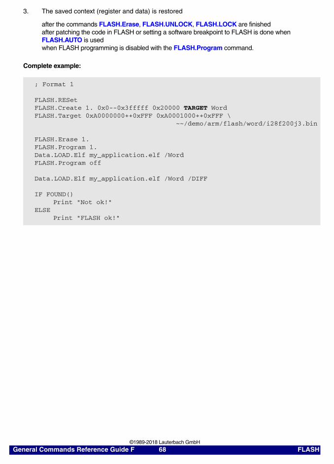
3. The saved context (register and data) is restored
after the commands FLASH.Erase, FLASH.UNLOCK, FLASH.LOCK are finishedafter patching the code in FLASH or setting a software breakpoint to FLASH is done when FLASH.AUTO is usedwhen FLASH programming is disabled with the FLASH.Program command.
Complete example:
; Format 1
FLASH.RESetFLASH.Create 1. 0x0--0x3fffff 0x20000 TARGET Word FLASH.Target 0xA0000000++0xFFF 0xA0001000++0xFFF \ ~~/demo/arm/flash/word/i28f200j3.bin
FLASH.Erase 1.FLASH.Program 1.Data.LOAD.Elf my_application.elf /WordFLASH.Program off
Data.LOAD.Elf my_application.elf /Word /DIFF
IF FOUND()Print "Not ok!"
ELSEPrint "FLASH ok!"
General Commands Reference Guide F 68 FLASH ©1989-2018 Lauterbach GmbH

Example for Format 2
FLASH: Intel Strata FLASH 28F320J3A, 16 bit mode, word access
CPU: ARM core
Memory configuration:
• FLASH from 0x0--0x3FFFFF
• RAM starting at address 0xA0000000
• <code_address>
- The code for the <flash_algorithm> is downloaded to the target RAM starting at <code_address>
- Required size for the code is size_of(<flash_algorithm>) + 32 byte
• <data_address>
- The address range starting with <data_address> is used as data range for <flash_algorithm>
- Required size for the data is <buffer_size> + 32 byte argument buffer + 256 byte stack
• <buffer_size>
<buffer_size> is the number of bytes which are transferred from the TRACE32 software to the target controlled FLASH programming routine in one step. Recommended buffer size is 4 KByte, smaller buffer sizes are also possible. The max. buffer size is 16 KByte.
• <flash_algorithm>
The FLASH algorithm can be found in ~~/demo/arm/flash/word/i28f200j3.bin
; Format 2
FLASH.RESetFLASH.Create 1. 0x0--0x3FFFFF 0x20000 TARGET Word
; <code_addr> <data_addr> <buffer_size> <flash_algorithm>FLASH.Target 0xA0000000 0xA0001000 0x1000 \ ~~/demo/arm/flash/word/i28f200j3.bin ; binary file only!
General Commands Reference Guide F 69 FLASH ©1989-2018 Lauterbach GmbH

Programming procedure:
1. The TRACE32 software takes care of saving the contents of
<code_address>++(size_of(<flash_algorithm>)+32 byte)<data_address>++(<buffer_size> + 32 byte argument buffer + 256 byte stack>)used CPU registers
before the commands FLASH.Erase, FLASH.UNLOCK, FLASH.LOCK are startedbefore patching the code in FLASH or setting a software breakpoint to FLASH is performed after FLASH.AUTO is usedwhen FLASH programming is enabled with the FLASH.Program command
2. The FLASH program is loaded to the target and the requested FLASH programming commands are executed.
3. The saved context (register and data) is restored.
after the commands FLASH.Erase, FLASH.UNLOCK, FLASH.LOCK are finishedafter patching the code in FLASH or setting a software breakpoint to FLASH is done when FLASH.AUTO is usedwhen FLASH programming is disabled with the FLASH.Program command.
Complete example:
; Format 2
FLASH.RESetFLASH.Create 1. 0x0--0x3FFFFF 0x20000 TARGET Word FLASH.Target 0xA0000000 0xA0001000 0x1000 \ ~~/demo/arm/flash/word/i28f200j3.bin
FLASH.Erase 1.FLASH.Program 1.Data.LOAD.Elf my_application.elf /WordFLASH.Program off
Data.LOAD.Elf my_application.elf /Word /DIFF
IF FOUND()Print "Not ok!"
ELSEPrint "FLASH ok!"
General Commands Reference Guide F 70 FLASH ©1989-2018 Lauterbach GmbH

Example 3 (Recommended to Test Your Own FLASH Algorithm)
Tips for writing your own FLASH algorithm can be found in “How to Write your own FLASH Algorithm” (flash_app_own_algorithm.pdf).
FLASH: Intel Strata FLASH 28F320J3A, 16 bit mode, word access
Memory configuration:
• FLASH from 0x0--0x3FFFFF
• RAM starting at address 0xA0000000
• <code_range>
- The code for my_flash_algorithm.elf is downloaded to <code_range>
- Required size for the code is size_of(my_flash_algorithm.elf) + 32 byte
• <data_range>
- The specified data range is used for my_flash_algorithm.elf
- <buffer_size> is the number of bytes which are transferred from the TRACE32 software to the target controlled FLASH programming routine in one step. Recommended buffer size is 4 KByte, smaller buffer sizes are also possible. The max. buffer size is 16 KByte.
- <buffer_size> = size_of(<data_range>) - 32 byte argument buffer - 256 byte stack
; Format 1 using your own FLASH algorithm
FLASH.RESetFLASH.Create 1. 0x0--0x3fffff 0x20000 TARGET Word
; <code_range> <data_range>FLASH.Target 0xA0000000++0xFFF 0xA0001000++0xFFF
Data.LOAD.Elf my_flash_algorithm.elf
FLASH.Erase ALLFLASH.Program ALLData.LOAD.Bin flash_contents.binFLASH.Program off
General Commands Reference Guide F 71 FLASH ©1989-2018 Lauterbach GmbH

Programming procedure:
1. The FLASH program is loaded to the target by the user.
2. The TRACE32 software saves the used CPU registers:
- Before the commands FLASH.Erase, FLASH.UNLOCK, FLASH.LOCK are started or
- When FLASH programming is enabled.
3. The requested FLASH commands are executed.
4. The saved CPU registers are restored:
- After the commands FLASH.Erase, FLASH.UNLOCK, FLASH.LOCK are finished or
- When FLASH programming is disabled.
Examples for /DualPort
Example for processor-internal FLASH:
Example for Cortex/ARM using dual-port access via AHB bus:
Example for /FirmWareRAM
FLASH declaration of LPC43xx internal FLASH:
See also
■ FLASH.TARGET2 ■ FLASH ■ FLASH.CFI ■ FLASH.state ❏ FLASH.TARGET.BUILD() ❏ FLASH.TARGET.FILE()
▲ ’FLASH Declaration in Detail’ in ’Onchip/NOR FLASH Programming User’s Guide’▲ ’Release Information’ in ’Release History’
; <code> <data> <buffer_size>FLASH.TARGET 0x40000000 0x40002000 0x1000 *.bin /DualPort
; <code> <data> <buffer_size>FLASH.TARGET 0x20000000 EAHB:0x20001000 0x1000 *.bin /DualPort
FLASH.TARGET 0x10000000 0x10001000 0x2000 \ ~~/demo/arm/flash/long/lpc4300.bin \ /STACKSIZE 0x200 /FirmWareRAM 0x10089FF0--0x10089FFF
General Commands Reference Guide F 72 FLASH ©1989-2018 Lauterbach GmbH

FLASH.TARGET2 Define second target controlled algorithm
Supports the simultaneous programming of multiple flash devices with two different flash algorithms. This allows to program for example processor internal and processor external NOR flash, HyperFlash or QSPI flash with a single programming command sequence.
The command syntax is the same as for the FLASH.TARGET command.
See also
■ FLASH.TARGET ■ FLASH ■ FLASH.CFI ■ FLASH.state ❏ FLASH.TARGET.BUILD() ❏ FLASH.TARGET2.FILE()
▲ ’Release Information’ in ’Release History’
Format 1: FLASH.TARGET2 <code_address> <data_address> <buffer_size> <file> \ [/STACKSIZE <size>] [/FirmWareRAM <address_range>] \ [/DualPort | /CORE <number>]
Format 2: FLASH.TARGET2 <code_range> <data_range> [<file>] \ [/STACKSIZE <size>] [/FirmWareRAM <address_range>] \ [/DualPort | /CORE <number>]
; set up declaration for off-chip flash 1FLASH.Create 1. 0x00000000--0x0001FFFF 0x10000 TARGET LongFLASH.TARGET 0xC0000000 0xD0000000 0x2000 \ ~~/demo/arm/flash/long/am29lv100.bin
; set up declaration for off-chip flash 2FLASH.Create 2. 0xA4000000--0xA401FFFF 0x4000 TARGET2 Long FLASH.Create 2. 0xA4020000--0xA43FFFFF 0x20000 TARGET2 Long FLASH.TARGET2 0xC0000000 0xD0000000 0x2000 \ ~~/demo/arm/flash/long/am29n256.bin…
; single flash programming sequence for both flash devicesFLASH.ReProgram ALL /EraseData.LOAD.Elf my_program.elfFLASH.ReProgram off
General Commands Reference Guide F 73 FLASH ©1989-2018 Lauterbach GmbH

FLASH.UNLOCK Unlock FLASH
Many FLASH devices provide a sector/block protection to avoid unintended erasing or programming operations. This protection has to be unlocked in order to erase or program a FLASH device.
Two unlocking schemes are used by FLASH devices:
1. Each individual sector/block has to be unlocked (individual unlocking).
2. The execution of a single unlock command sequence on an address range unlocks the complete FLASH device (parallel unlocking).
Re-locking has to be executed usually sector by sector.
Please refer to the data sheet of your FLASH device, to find out which scheme is used by your FLASH device.
Example for 1 (individual unlocking):
INTEL 28F128L18 at address 0x0, connected to the CPU via a 16 bit data bus
Format: FLASH.UNLOCK <unit> | <address_range> | ALL | off
<unit> Unlock the specified unit.
ALL Unlock all FLASH sectors.
off (no effect)
FLASH.RESet ; reset FLASH declaration
FLASH.CFI 0x0 Word ; declare FLASH sectors via ; CFI query
FLASH.UNLOCK ALL ; unlock each sector individually
… ; erasing and programming
FLASH.LOCK ALL ; re-lock each sector individually
General Commands Reference Guide F 74 FLASH ©1989-2018 Lauterbach GmbH

Example for 2 (parallel unlocking):
INTEL 28F128J3 at address 0x0, connected to the CPU via a 16 bit data bus, each sector 128KByte
See also
■ FLASH ■ FLASH.LOCK ■ FLASH.state
▲ ’TRACE32 Tool-based Programming’ in ’Tips to Solve NOR FLASH Programming Problems’▲ ’Programming Commands’ in ’Onchip/NOR FLASH Programming User’s Guide’
FLASH.RESet ; reset FLASH declaration
FLASH.CFI 0x0 Word ; declare FLASH sectors via ; CFI query
FLASH.UNLOCK 0x0--0x1ffff ; execute a single unlock command; by using an address range; inside of a FLASH sector (faster)
… ; erasing and programming
FLASH.LOCK ALL ; re-lock each sector individually
General Commands Reference Guide F 75 FLASH ©1989-2018 Lauterbach GmbH

FLASH.UNSECUREerase Unsecure a device
Debug access is no longer possible if the CPU is secured by programming special FLASH address locations.
In these cases, the FLASH.UNSECUREerase command can be used to unsecure a device by sending special commands via the debug interface. As a result, the FLASH is completely erased by the unsecure sequence. Debug access is now possible again.
See also
■ FLASH ■ FLASH.state
Format: FLASH.UNSECUREerase
SYStem.CPU <cpu_type>FLASH.UNSECUREeraseSYStem.Up
NOTE: FLASH.UNSECUREerase is a CPU specific command.
General Commands Reference Guide F 76 FLASH ©1989-2018 Lauterbach GmbH

FLASHFILE
FLASHFILE NAND flash and serial flash devices
NAND FLASH devices and serial FLASH devices can be programmed and erased by the FLASHFILE command group.
• For a description of the NAND FLASH programming concept, see “NAND FLASH Programming User’s Guide” (nandflash.pdf).
• For a description of the Serial FLASH programming concept, see “Serial FLASH Programming User’s Guide” (serialflash.pdf).
See also
■ FLASHFILE.BSDLaccess ■ FLASHFILE.BSDLFLASHTYPE ■ FLASHFILE.CONFIG ■ FLASHFILE.COPY ■ FLASHFILE.COPYSPARE ■ FLASHFILE.Create ■ FLASHFILE.DUMP ■ FLASHFILE.Erase ■ FLASHFILE.GETBADBLOCK ■ FLASHFILE.GETEXTCSD ■ FLASHFILE.GETID ■ FLASHFILE.GETONFI ■ FLASHFILE.List ■ FLASHFILE.LOAD ■ FLASHFILE.LOADALL ■ FLASHFILE.LOADECC ■ FLASHFILE.LOADSPARE ■ FLASHFILE.LOCK ■ FLASHFILE.MSYSDLL ■ FLASHFILE.RESet ■ FLASHFILE.SAVE ■ FLASHFILE.SAVEALL ■ FLASHFILE.SAVEECC ■ FLASHFILE.SAVESPARE ■ FLASHFILE.Set ■ FLASHFILE.SETEXTCSD ■ FLASHFILE.SPICMD ■ FLASHFILE.state ■ FLASHFILE.TARGET ■ FLASHFILE.UNLOCK ■ FLASH ■ BSDL.FLASH ❏ FLASHFILE.SPAREADDRESS()
▲ ’FLASHFILE Function’ in ’General Functions’▲ ’Introduction’ in ’NAND FLASH Programming User’s Guide’▲ ’Introduction’ in ’Serial FLASH Programming User’s Guide’
FLASHFILE.BSDLaccess Enables FLASH access via boundary scan
Enables or disables FLASH memory access via boundary scan. The boundary scan chain must be configured with BSDL.FLASH.IFDefine and BSDL.FLASH.IFMap.
See also
■ FLASHFILE ■ FLASHFILE.state
Format: FLASHFILE.BSDLaccess ON | OFF
General Commands Reference Guide F 77 FLASHFILE ©1989-2018 Lauterbach GmbH

FLASHFILE.BSDLFLASHTYPE Define FLASH type
Declaration of FLASH memories.
See also
■ FLASHFILE ■ FLASHFILE.state
FLASHFILE.CONFIG Configure FLASH
NAND FLASH
NAND FLASH devices use a common multiplexed bus for data, address and command transfers. With the two signals (Command Latch Enable, Address Latch Enable) the access is latched to the appropriate register. If the two signals are inactive, the access is performed to the I/O register.
Normally CLE and ALE are part of the address on the external bus. Thus NAND FLASHs data, address and command register can be mapped to the processors external memory space.
The user has to define the following three addresses:
Format: FLASHFILE.BSDLFLASHTYPE <flash_family_code>
<flash_family_code> Determines the programming algorithm. Supported flash family codes are listed on http://www.lauterbach.com/ylist.html in the Code column.
Format 1:NAND FLASH
FLASHFILE.CONFIG <cmd_reg> <addr_reg> <io_reg>
Format 2:Serial FLASH
FLASHFILE.CONFIG <spi_tx> <spi_rx> <cs_reg> <cs_port>
<cmd_reg> Address of the NAND FLASH command register
<addr_reg> Address of the NAND FLASH address register
<io_reg> Address of the NAND FLASH I/O register
General Commands Reference Guide F 78 FLASHFILE ©1989-2018 Lauterbach GmbH

Example: The NAND FLASH device chip select is assigned to the address 0xa0000000.
For a processor with integrated NAND FLASH controller this command can be omitted. Instead a script for the configuration of such a controller must be executed. Scripts for the supported NAND FLASH controllers are located in the demo directory.
Serial FLASH tbd.
See also
■ FLASHFILE ■ FLASHFILE.state
▲ ’Scripts for NAND Flash Programming’ in ’NAND FLASH Programming User’s Guide’
FLASHFILE.COPY Copy to FLASH
The source range data is copied to the defined target address. It is useful to write some memory data to FLASH memory.
See also
■ FLASHFILE ■ FLASHFILE.state
Format: FLASHFILE.COPY <source_range> <target_address> [/<option>]
<option>: ComPare | DIFF | wordSWAP | LongSWAP | QuadSWAP
<option> For a description of the options, see FLASHFILE.LOAD.binary.
; Copy the 2MB virtual memory data at 0x0 to the NAND FLASH address at 0x100000, the writing scheme is the skipped wayFLASHFILE.COPY VM:0x0--0x1FFFFF 0x100000
; Compare the data between virtual memory and NAND FLASHFLASHFILE.COPY VM:0x0--0x1FFFFF 0x100000 /ComPare
CPU NAND FLASH
ALE
CLE
Data bus
A17
A18
<cmd_reg>:
<addr_reg>:
<io_reg>:
0xa0020000
0xa0040000
0xa0000000
General Commands Reference Guide F 79 FLASHFILE ©1989-2018 Lauterbach GmbH

FLASHFILE.COPYSPARE Copy to spare area of NAND FLASH
The source range data is copied from the TRACE32 virtual memory (VM:) to the defined spare area address of the NAND flash.
Example:
See also
■ FLASHFILE ■ FLASHFILE.state ❏ FLASHFILE.SPAREADDRESS()
Format: FLASHFILE.COPYSPARE <source_range> <spare_area_address> [/<option>]
<option>: ComPare | DIFF | wordSWAP | LongSWAP | QuadSWAP
<option> For a description of the options, see FLASHFILE.LOAD.binary.
; NAND Page Size (example for main/spare: 2KB/64B); From the TRACE32 virtual memory, copy 64B to the spare area that; corresponds to the NAND FLASH main address 0x100000FLASHFILE.COPYSPARE VM:0x0--0x3F FLASHFILE.SPAREADDRESS(0x100000)
;or
;the spare area address 0x8000 corresponds to the main area 0x100000FLASHFILE.COPYSPARE VM:0x0--0x3F 0x8000
General Commands Reference Guide F 80 FLASHFILE ©1989-2018 Lauterbach GmbH

FLASHFILE.Create Declaration of flash memories: create a block/sector
Generally, the FLASHFILE.Create command is only used for programming non-uniform serial flash memories in TRACE32. You do not need to use FLASHFILE.Create if the erase unit size of the sector or block is uniform.
The FLASHFILE.Create command instructs TRACE32 to correctly calculate the non-uniform flash block size/flash sector size.
Example: In this script, TRACE32 is informed that the serial flash device S25FL129 has 32 boot sectors, each with a size of 4Kbyte, and 254 main sectors, each with a size of 64KByte.
See also
■ FLASHFILE ■ FLASHFILE.List ■ FLASHFILE.state
Format: FLASHFILE.Create <address_range> <erase_unit_size> <bus_width>
<erase_unit_size>:
<sector> | <block>
<bus_width>: Byte | Word
<address_range> Address range within the flash memory.
<erase_unit_size> The erase unit is called sector for serial flash and block for NAND flash memories.
In case of a NAND flash:A block equals the size of an ERASE BLOCK of the NAND command (0x60/0xD0).
In case of a Serial flash:A sector equals the size of an ERASE SECTOR of the Serial flash erase command (0x20/0x40/0xD8).
<bus_width> The bus width parameter defines the external flash memory bus size (8-bit, 16-bit).
FLASHFILE.Create 0x0--0x1FFFF 0x1000 Byte ;boot sectorsFLASHFILE.Create 0x20000--0xFFFFFF 0x10000 Byte ;main sectors
General Commands Reference Guide F 81 FLASHFILE ©1989-2018 Lauterbach GmbH

FLASHFILE.DUMP Dump FLASH
Reads the FLASH memory to the Data.dump window. You can read the main and spare data from NAND FLASH devices. You can find the matched spare area easily from the main area dump window by the Track option.
See also
■ FLASHFILE ■ FLASHFILE.state
▲ ’Release Information’ in ’Release History’
Format: FLASHFILE.DUMP [<address> | <range>] [/<format> | <option> …]
<format>: NoHex | NoAsciiByte | Word | Long | Quad | TByte | HByte | SByteBE | LE
<option>: MAINSPARETrackReFresh
General Commands Reference Guide F 82 FLASHFILE ©1989-2018 Lauterbach GmbH

FLASHFILE.Erase Erase FLASH
Erases the FLASH memory.
Examples:
See also
■ FLASHFILE ■ FLASHFILE.state
Format: FLASHFILE.Erase <range> /EraseBadBlocks
EraseBadBlocks Includes bad blocks in the operation.
;Erase NAND FLASH except bad blocksFLASHFILE.Erase 0x0--0xFFFF
;Erase NAND FLASH including bad blocksFLASHFILE.Erase 0x0--0xFFFF /EraseBadBlocks
MAIN SP
FLASHFILE.Erase
Bad
FLASHFILE.ERASE /EraseBadBlocks
1
2
3
5
N
4
MAIN SP
Bad4
MAIN SP
Bad
1
2
3
5
N
4
MAIN SP
General Commands Reference Guide F 83 FLASHFILE ©1989-2018 Lauterbach GmbH

FLASHFILE.GETBADBLOCK Get the bad block addresses
Displays the bad block addresses within the specified range. If the NAND FLASH block #0 is bad, then TRACE32 cannot detect any bad blocks in the NAND FLASH device.
See also
■ FLASHFILE ■ FLASHFILE.state
FLASHFILE.GETEXTCSD Get the extended CSD register
Gets the extended CSD register, which defines the MMC flash properties and selected modes. Each register byte is described in the JEDEC standard eMMC documentation.
See also
■ FLASHFILE ■ FLASHFILE.SETEXTCSD ■ FLASHFILE.state
Format: FLASHFILE.GETBADBLOCK <range>
Format: FLASHFILE.GETEXTCSD
FLASHFILE.GETEXTCSDAREA.view ;display the result in the AREA.view window
General Commands Reference Guide F 84 FLASHFILE ©1989-2018 Lauterbach GmbH

FLASHFILE.GETID Get ID
Get the manufacture and device ID from FLASH. This command is mainly used to test the communication between the CPU and FLASH device.
See also
■ FLASHFILE ■ FLASHFILE.state
FLASHFILE.GETONFI Display ONFI
Displays the Open NAND FLASH Interface (ONFI) specification. This command works only for NAND flash devices that support ONFI.
See also
■ FLASHFILE ■ FLASHFILE.state
Format: FLASHFILE.GETID
Format: FLASHFILE.GETONFI
General Commands Reference Guide F 85 FLASHFILE ©1989-2018 Lauterbach GmbH

FLASHFILE.List List blocks or sectors of FLASH memory
Opens the FLASHFILE.List window, displaying the list of blocks or sectors defined with the FLASHFILE.Create command. Each block or sector corresponds to one erase unit size of the flash memory.
Example: In this script, TRACE32 is informed that the serial flash device S25FL129 has 32 boot sectors, each with a size of 4Kbyte, and 254 main sectors, each with a size of 64KByte.
See also
■ FLASHFILE ■ FLASHFILE.Create ■ FLASHFILE.state
Format: FLASHFILE.List
FLASHFILE.Create 0x0--0x1FFFF 0x1000 Byte ;boot sectorsFLASHFILE.Create 0x20000--0xFFFFFF 0x10000 Byte ;main sectors
A Each row corresponds to one 4KB boot sector. B Each row corresponds to one 64KB main sector.
A
B
General Commands Reference Guide F 86 FLASHFILE ©1989-2018 Lauterbach GmbH

FLASHFILE.LOAD Load files to FLASH
Using the FLASHFILE.LOAD command group, you can load binary, ELF, Intel HEX, and Srecord files to the NAND FLASH.
See also
■ FLASHFILE.LOAD.binary ■ FLASHFILE.LOAD.Elf ■ FLASHFILE.LOAD.IntelHex ■ FLASHFILE.LOAD.Srecord ■ FLASHFILE ■ FLASHFILE.state
FLASHFILE.LOAD.binary Write FLASH[Examples]
The data from the binary <file> is programmed to the flash. If the command is called without <address> and <range>, the complete file will be programmed to flash beginning from target address 0.
Format: FLASHFILE.LOAD.binary <file> [<address> <range>] /<option>
<option>: WriteBadBlocks | ComPare | DIFF | wordSWAP | LongSWAP | QuadSWAP | SKIP <offset> | ZIPLOAD | NoFF | NoZero
<address> • File format without address information (e.g. binary): base address of the flash memory
• File format with address information: address offset of the flash memory
<range> • If specified, only the data within the address range will be loaded. Data outside this address range will be ignored.
• If specified for file formats without address information, the start address of <range> is used as base address and <address> will be ignored.
ComPare Verify the contents of <file> against the flash main area.
DIFF Compare the contents of the FLASH with the file contents. See example.
LongSWAP Swaps high and low bytes of a 32-bit word during load.
NoFF Skips the pages of a <file> that contain only 0xFF.
General Commands Reference Guide F 87 FLASHFILE ©1989-2018 Lauterbach GmbH

Example 1
NoZero Skips the pages of a <file> that contain only 0x00.
NOTE: Pages containing only 0xFF or 0x00 can cause unexpected ECC code generation on the NAND flash spare area. The purpose of the options NoFF and NoZero is to prevent unexpected ECC code generation by skipping these pages.
For information about ECC, see “Appendix A: ECC (Error Correction Code)” (nandflash.pdf).
QuadSWAP Swaps high and low bytes of a 64-bit word during load.
SKIP If the option SKIP <offset> is specified, the first <offset> bytes of the file are omitted.
wordSWAP Swaps high and low bytes of a 16-bit word during load.
WriteBadBlock Program NAND Flash including bad blocks. (Does not apply to serial flash). See example.
ZIPLOAD Speeds up the transfer of compressed files through the JTAG interface, decompresses and programs the files to the FLASH memory on the target board.Requirements for using ZIPLOAD:• SDRAM > 256 KB; SDRAM > 512 KB is recommended.• Configure the CPU clock and SDRAM clock.See example.
FLASHFILE.RESet
; FLASHFILE.Config <cmd_reg> <addr_reg> <io_reg>FLASHFILE.Config 0xA0040000 0xA0020000 0xA0000000
; FLASHFILE.TARGET <code_range> <data_range> <file>FLASHFILE.TARGET 0x1000++0x1FFF 0x3000++0x1FFFF \ ~~/demo/arm/flash/word/nand1216.bin
; get the flash identificationFLASHFILE.GETID
; erase first 1 MByteFLASHFILE.Erase 0++0xFFFFF
; write file to NAND FLASHFLASHFILE.LOAD my_file.bin 0++0xFFFFF
General Commands Reference Guide F 88 FLASHFILE ©1989-2018 Lauterbach GmbH

Example 2 - ZIPLOAD option:
Example 3 - Illustration of the WriteBadBlock option:
Example 4 - DIFF option:
See also
■ FLASHFILE.LOAD
FLASHFILE.LOAD * 0x0 /ZIPLOAD ;the asterisk (*) lets you browse ;for the compressed file you want ;to load
; compare the contents of the NAND FLASH with the file contentsFLASHFILE.LOAD.Elf data.elf /DIFF
; FOUND() returns TRUE if a difference was foundIF FOUND() PRINT "Not ok!"ELSE PRINT "NAND FLASH ok!"
My_file NAND My_file NAND
Bad
FLASHFILE.LOAD … /WriteBadBlockFLASHFILE.LOAD …
1
2
3
5
N
4
1
2
3
5
N
4
1
2
3
4
N-1
1
2
3
5
N
4Bad
Main SP Main SP
General Commands Reference Guide F 89 FLASHFILE ©1989-2018 Lauterbach GmbH

FLASHFILE.LOAD.Elf Load ELF file
Loads an ELF file to the FLASH memory on the target.
See also
■ FLASHFILE.LOAD
FLASHFILE.LOAD.IntelHex Load Intel hex file
Loads a file in the intel HEX format to the NAND Flash.
See also
■ FLASHFILE.LOAD
Format: FLASHFILE.LOAD.Elf <file> [<address> <range>] [/<option>]
<option>: ComPare | DIFFwordSWAP | LongSWAP | QuadSWAP
<option> For a description of the options, etc., see FLASHFILE.LOAD.binary.
FLASHFILE.LOAD.ELF *.* -0x20000000 0x0--0xFFFFFF
Format: FLASHFILE.LOAD.IntelHex <file> [<address> <range>] [/<option>]
<option>: ComPare | DIFFwordSWAP | LongSWAP | QuadSWAP
<option> For a description of the options, etc., see FLASHFILE.LOAD.binary.
General Commands Reference Guide F 90 FLASHFILE ©1989-2018 Lauterbach GmbH

FLASHFILE.LOAD.Srecord Load an "Srecord" file
Loads a file in the Srecord format to the NAND Flash.
See also
■ FLASHFILE.LOAD
FLASHFILE.LOADALL Load to main area and spare area
Loads <file> to the main area and the spare area of the NAND flash memory. This is useful for cloning a NAND flash device.
See also
■ FLASHFILE ■ FLASHFILE.state
Format: FLASHFILE.LOAD.S1record <file> [<address> <range>] [/<option>] FLASHFILE.LOAD.S2record <file> [<address> <range>] [/<option>] FLASHFILE.LOAD.S3record <file> [<address> <range>] [/<option>]
<option>: ComPare | DIFFwordSWAP | LongSWAP | QuadSWAP
<option> For a description of the options, etc., see FLASHFILE.LOAD.binary.
Format: FLASHFILE.LOADALL <file> [<address> <range>] [/<option>]
<option>: ComPare | DIFF | WriteBadBlockswordSWAP | LongSWAP | QuadSWAP
<option> For a description of the options, etc., see FLASHFILE.LOAD.binary.
General Commands Reference Guide F 91 FLASHFILE ©1989-2018 Lauterbach GmbH

FLASHFILE.LOADECC Load ECC file to spare area[Example]
Loads a saved ECC file to the spare area of a NAND Flash. TRACE32 calculates the location of the spare area based on the range of the main area, which is known to users.
Format: FLASHFILE.LOADECC <params> (deprecated)Use FLASHFILE.SAVEECC + FLASHFILE.LOADSPARE.
<params>: <file> <range | value> <ref_size> <ecc_size> <location>
<file> Source file containing the error correction code (ECC).
<range> Range of the main area.
<value> Start address of the main area.
<ref_size> The same <ref_size> with which the ECC file was saved by the FLASHFILE.SAVEECC.* command. See also [B] below.
<ecc_size> The same length of the ECC word with which the ECC file was saved by the FLASHFILE.SAVEECC.* command.See also [A] below.
<location> Spare area address (byte) to which the ECC file is loaded in the spare area of the NAND Flash. See also [D] below.
General Commands Reference Guide F 92 FLASHFILE ©1989-2018 Lauterbach GmbH

Example:
See also
■ FLASHFILE ■ FLASHFILE.SAVEECC ■ FLASHFILE.state
▲ ’Scripts for NAND Flash Programming’ in ’NAND FLASH Programming User’s Guide’
; <range> <ref_size>FLASHFILE.SAVEECC.hamming file.hmg 0x0--0xFFFF 512.
; <range> <ref_size> <ecc_size> <location>FLASHFILE.LOADECC file.hmg 0x0--0xFFFF 512. 3. 8.
;view the result of FLASHFILE.SAVEECC.hamming and FLASHFILE.LOADECC AREA.view
A In this example, each ECC word consists of 3 bytes (= <ecc_size>).
B In this example, 512 bytes in the source memory range are represented by an ECC word. (512 = <ref_size>)
C DUMP of file.hmg, which was created with FLASHFILE.SAVEECC.hamming.
D <location> address in the spare area to which file.hmg was loaded with FLASHFILE.LOADECC. In this example, the <location> address has an offset of 8 bytes.
A B
C
D
General Commands Reference Guide F 93 FLASHFILE ©1989-2018 Lauterbach GmbH

FLASHFILE.LOADSPARE Write NAND FLASH spare area
The data from <file> is written to the spare area on the address and size specified by <range>. At first only binary files are supported.
See also
■ FLASHFILE ■ FLASHFILE.state ❏ FLASHFILE.SPAREADDRESS()
FLASHFILE.LOCK Lock the FLASH device
Locks the FLASH device.
See also
■ FLASHFILE ■ FLASHFILE.state ■ FLASHFILE.UNLOCK
Format: FLASHFILE.LOADSPARE <file> <range> /WriteBadBlocks /ComPare
Format: FLASHFILE.LOCK <range>
Bad
FLASHFILE.LOADSPARE
My_File_Spare NandMain SP
1
2
3
5
N
4
1
2
3
4
N-1
General Commands Reference Guide F 94 FLASHFILE ©1989-2018 Lauterbach GmbH

FLASHFILE.MSYSDLL Access an M-Systems DiskOnChip flash device
Accesses an M-Systems DiskOnChip flash device.
See also
■ FLASHFILE ■ FLASHFILE.state
FLASHFILE.RESet Reset FLASH configuration
The setup for the FLASH device is cleared and set to the default values.
See also
■ FLASHFILE ■ FLASHFILE.state
▲ ’Scripts for eMMC Controllers’ in ’eMMC FLASH Programming User’s Guide’▲ ’Scripts for NAND Flash Programming’ in ’NAND FLASH Programming User’s Guide’▲ ’Scripts for SPI Controllers’ in ’Serial FLASH Programming User’s Guide’
Format: FLASHFILE.MSYSDLL <file> [<cmd> …]
Format: FLASHFILE.RESet
General Commands Reference Guide F 95 FLASHFILE ©1989-2018 Lauterbach GmbH

FLASHFILE.SAVE Save FLASH
The data whose address and size is specified by <range> is read from the NAND FLASH main area and written to <file>.
See also
■ FLASHFILE ■ FLASHFILE.state
FLASHFILE.SAVEALL Save the main area and the spare area
Saves the main area and the spare area of the NAND flash memory to <file>. This is useful for cloning a NAND flash device.
See also
■ FLASHFILE ■ FLASHFILE.state
Format: FLASHFILE.SAVE <file> <range>
Format: FLASHFILE.SAVEALL <file> <range> [/SkipBadBlocks]
SkipBadBlocks Skips bad blocks while saving the contents of the NAND Flash main area to <file>.
Bad
FLASHFILE.SAVE
FileNand
Main SP
Bad
1
2
3
4
N-1
1
2
3
4
N-1
General Commands Reference Guide F 96 FLASHFILE ©1989-2018 Lauterbach GmbH

FLASHFILE.SAVEECC Save error correction code (ECC) to file
The FLASHFILE.SAVEECC command group is used to generate and save error correction code (ECC) to file. The ECC is generated from the target application residing in the main area of a flash device.
Depending on the FLASHFILE.SAVEECC.* command used, TRACE32 generates the ECC with one of the following algorithms:
• Bose-Chaudhuri-Hocquenghem (BCH) algorithm
• Hamming algorithm
• Reed-Solomon algorithm
Use FLASHFILE.LOADECC to load ECC files to the spare area of a flash device.
See also
■ FLASHFILE.SAVEECC.BCH ■ FLASHFILE.SAVEECC.hamming ■ FLASHFILE.SAVEECC.ReedSolomon ■ FLASHFILE ■ FLASHFILE.LOADECC ■ FLASHFILE.state
FLASHFILE.SAVEECC.BCH Save ECC with BCH algorithm[Example]
Saves the error correction code (ECC) to file using the BCH algorithm.
Format: FLASHFILE.SAVEECC.BCH <params> [/REVERSE | /SWAP | /LAYOUT <layout_block_size> <offset> <bytes_per_block>]
<params>: <file> <range> <ref_size> <g_field> <err_correc>
<file> Destination file for the error correction code (ECC).
<range> Source memory range for which you want to save the ECC to file.
<ref_size> Number of bytes that will be represented by an ECC word.
Example: One ECC word is generated for every 512. bytes of the <range> if the <ref_size> is set to 512. bytes.
<g_field> Dimension of the Galois field.
<err_correc> Error correction capability (measured in bit) of the BCH code.
General Commands Reference Guide F 97 FLASHFILE ©1989-2018 Lauterbach GmbH

Examples for FLASHFILE.SAVEECC.BCH
Example 1:
SWAP Swaps the read byte order (byte access) of each ECC word.
Example for the 4 byte ECC word 0x12345678:
REVERSE Reverses the read bit order (bit access) of each ECC word.
Example: The ECC word is 0xC1, i.e. 1 byte [7:0]. The REVERSE option changes bit 7 to bit 0, bit 6 to bit 1, and so on. Thus, the resulting reversed ECC word is 0x83.
LAYOUT For a description of LAYOUT, see FLASHFILE.SAVEECC.hamming.
For examples for FLASHFILE.SAVEECC.BCH ... /LAYOUT, see examples 2 and 3 below.
;save the ECC file: <range> <ref_s.><g_field><err_correc>FLASHFILE.SAVEECC.BCH file.bch 0x0--0xFFFF 512. 13. 8.
;open an AREA window to view the resultAREA.view
;optionally, view the ECC file with the DUMP command;for WIDTH use the width of the generated ECC wordDUMP file.bch /WIDTH 13.
0x|12|34|56|78|Without /SWAP
0x|78|56|34|12|With /SWAP
0x| |0y|1100|0001
1Without /REVERSE
0y|1000|0011With /REVERSE
C
0x| | 38
<g_field>
<err_correc>
<ref_size>
Generated 13-byte ECC word
General Commands Reference Guide F 98 FLASHFILE ©1989-2018 Lauterbach GmbH

Example 2:
Example 3:
See also
■ FLASHFILE.SAVEECC
▲ ’Scripts for NAND Flash Programming’ in ’NAND FLASH Programming User’s Guide’
;without LAYOUT: ECC in linear formFLASHFILE.SAVEECC.BCH aaa.bin 0x0--0xFFFFF 512. 13. 8. DUMP aaa.bin
;with LAYOUT: ECC in non-linear formFLASHFILE.SAVEECC.BCH aab.bin 0x0--0xFFFFF 512. 13. 8. \ /LAYOUT 0x30 5. 3.DUMP aab.bin
A <layout_block_size> = 0x30
B <offset> = 5
C <bytes_per_block> = 3
FLASHFILE.SAVEECC.BCH spare-bch.bin 0x0--0xFFFFF 512. 13. 8. \ /LAYOUT 0x10 2. 13.
A C
Result without /LAYOUT Result with /LAYOUT
A CCompare with [C] on the right.
B
General Commands Reference Guide F 99 FLASHFILE ©1989-2018 Lauterbach GmbH

FLASHFILE.SAVEECC.hamming Save ECC with Hamming algorithm[Examples]
Saves the error correction code (ECC) to file using the Hamming algorithm. By default, the ECC words generated by the Hamming algorithm are fixed (3 bytes). Consequently, you do not need to specify the <ecc_size>, but only <file>, <range>, and <ref_size>.
Format: FLASHFILE.SAVEECC.hamming <file> <range> <ref_size> [/SWAP | /LAYOUT <layout_block_size> <offset> <bytes_per_block>]
<file> Destination file for the error correction code (ECC).
<range> Source memory range for which you want to save the ECC to file.
<ref_size> Number of bytes that will be represented by an ECC word.Example: One ECC word is generated for every 512. bytes of the <range> if the <ref_size> is set to 512. bytes.
SWAP In the generated 3-byte ECC words, the location of ECC0 and ECC1 is swapped. The location of ECC2 remains fixed.
Example:
LAYOUT Without LAYOUT: The error correction code (ECC) is written to file in linear form.
With LAYOUT: The ECC is written to file in non-linear form and the layout of the ECC is modified by the arguments <layout_block_size>, <offset>, and <bytes_per_block>. See examples 2 and 3 below.
Without /SWAP
With /SWAP
ECC0 ECC1 ECC2FF 3C 0F69 AA 96
ECC0 ECC1 ECC23C FF 0FAA 69 96
General Commands Reference Guide F 100 FLASHFILE ©1989-2018 Lauterbach GmbH

Examples for FLASHFILE.SAVEECC.hamming
Example 1:
Example 2:
;save the ECC file: <range> <ref_sizeFLASHFILE.SAVEECC.hamming file.hmg 0x0--0xFFFF 512.
AREA.view ;open an AREA window to view the result
;optionally, view the ECC file with the DUMP command;use WIDTH 3. because each ECC word is 3 bytesDUMP file.hmg /WIDTH 3.
;without LAYOUT: ECC in linear formFLASHFILE.SAVEECC.hamming aaa.bin 0x0--0xFFFFF 512. DUMP aaa.bin
;with LAYOUT: ECC in non-linear formFLASHFILE.SAVEECC.hamming aab.bin 0x0--0xFFFFF 512. /LAYOUT 0x30 5. 3.DUMP aab.bin
A <layout_block_size> = 0x30
B <offset> = 5
C <bytes_per_block> = 3
Generated 3-byte ECC word
<ref_size>
A
B
C
Result without /LAYOUT Result with /LAYOUT
A C
General Commands Reference Guide F 101 FLASHFILE ©1989-2018 Lauterbach GmbH

Example 3:
See also
■ FLASHFILE.SAVEECC
▲ ’Scripts for NAND Flash Programming’ in ’NAND FLASH Programming User’s Guide’
FLASHFILE.SAVEECC.hamming spare-ham.bin 0x0--0xFFFFF 256. \ /LAYOUT 0x40 40. 24.
General Commands Reference Guide F 102 FLASHFILE ©1989-2018 Lauterbach GmbH

FLASHFILE.SAVEECC.ReedSolomon Save ECC with Reed-S. algorithm
Saves the error correction code (ECC) to file using the Reed-Solomon algorithm.
By default, one ECC word is 10 bytes for 4-bits error correction. Consequently, you do not need to specify the <ecc_size>, but only <file> and <range>.
Examples for FLASHFILE.SAVEECC.ReedSolomon
Example 1:
Format: FLASHFILE.SAVEECC.ReedSolomon <file> <range> [/LAYOUT <layout_block_size> <offset> <bytes_per_block>]
<file> Destination file for the error correction code (ECC).
<range> Source memory range for which you want to save the ECC to file.
LAYOUT For a description of LAYOUT, see FLASHFILE.SAVEECC.hamming.
For examples of FLASHFILE.SAVEECC.ReedSolomon ... /LAYOUT, see examples 2 and 3 below.
;view the result of FLASHFILE.SAVEECC.ReedSolomon in the AREA windowAREA.view
; <range> FLASHFILE.SAVEECC.ReedSolomon file.rs 0x0--0xFFFF
;optionally, view the ECC file with the DUMP command;use WIDTH 10. because each ECC word is 10 bytesDUMP file.rs /WIDTH 10.
<ref_size>
Generated 10-byte ECC word
General Commands Reference Guide F 103 FLASHFILE ©1989-2018 Lauterbach GmbH

Example 2:
Example 3:
See also
■ FLASHFILE.SAVEECC
▲ ’Scripts for NAND Flash Programming’ in ’NAND FLASH Programming User’s Guide’
;without LAYOUT: ECC in linear formFLASHFILE.SAVEECC.ReedSolomon aaa.bin 0x0--0xFFFFDUMP aaa.bin
;with LAYOUT: ECC in non-linear formFLASHFILE.SAVEECC.ReedSolomon aab.bin 0x0--0xFFFF /LAYOUT 0x30 5. 3.DUMP aab.bin
A <layout_block_size> = 0x30
B <offset> = 5
C <bytes_per_block> = 3
FLASHFILE.SAVEECC.ReedSolomon spare-rs.bin 0x0--0xFFFF \ /LAYOUT 0x10 6. 10.
A C
Result without /LAYOUT Result with /LAYOUT
A C
B
General Commands Reference Guide F 104 FLASHFILE ©1989-2018 Lauterbach GmbH

FLASHFILE.SAVESPARE Read NAND FLASH spare area
The data whose address and size is specified by <range> is read from the NAND FLASH spare area and written to <file>.
See also
■ FLASHFILE ■ FLASHFILE.state ❏ FLASHFILE.SPAREADDRESS()
FLASHFILE.Set Modify FLASH data
Modifies the contents of FLASH data at defined <address>. The maximum size of modifying is a block size of the flash.
See also
■ FLASHFILE ■ FLASHFILE.state
Format: FLASHFILE.SAVESPARE <file> <range>
Format: FLASHFILE.Set <address> | <range> %<format> <data>
<format>: Byte | Word | Long | Quad | …
; Write 4Bytes data 0x12345678 at the address 0x100000;FLASHFILE.Set 0x100000 %LE %LONG 0x12345678
; Write data 0x0 at the address range 0x100000++0xFFF;FLASHFILE.Set 0x100000++0xFFF %BYTE 0x0
Bad
FLASHFILE.SAVESPARE
FileNand
Main SP
Bad
1
2
3
4
N-1
1
2
3
4
N-1
General Commands Reference Guide F 105 FLASHFILE ©1989-2018 Lauterbach GmbH

FLASHFILE.SETEXTCSD Modify the extended CSD register
Modifies the extended CSD register by using the MMC command CMD6.
Example: Partition switch in the eMMC flash
See also
■ FLASHFILE ■ FLASHFILE.GETEXTCSD ■ FLASHFILE.state
Format: FLASHFILE.SETEXTCSD <index> <data>
;The Extended CSD register index 179. is the PARTITIOM_CONFIG register.;The register bit flag describes in the JEDEC standard eMMC;documentation.
FLASHFILE.SETEXTCSD 179. 0x00 ; access: partition null, no boot, ; access: no boot partition
FLASHFILE.SETEXTCSD 179. 0x49 ; access: partition boot 1
FLASHFILE.SETEXTCSD 179. 0x4A ; access: partition boot 2
General Commands Reference Guide F 106 FLASHFILE ©1989-2018 Lauterbach GmbH

FLASHFILE.SPICMD Send data to SPI FLASH device[Examples]
Sends FLASH-device-specific <data> from TRACE32 to a SPI FLASH device. The <data> can be any valid FLASH command sequence. For <data> that can be sent, refer to the FLASH manufacturer’s documentation.
Example 1: The SPI FLASH reads the <number_of_bytes>, and then TRACE32 sends the bytes read by the SPI FLASH to the specified <address> in the TRACE32 virtual memory (VM:).
Format: FLASHFILE.SPICMD [%<format>] <data> … [/<option>]
<format>: Byte | Word | Long | …
<option>: READ <number_of_bytes> [<address>]
Byte (default), Word, Long, …
Data size for integer constants. See “Keywords for <width>”, page 11.
<data> Any valid FLASH command sequence you want to send to the SPI FLASH, such as commands, addresses, dummy cycles, etc.
Examples of SPI-FLASH-device commands:• 0x9F // the READ ID command• 0x03 0x00 0x10 0x00 // the READ command with arguments
0x3 is the READ command. The three arguments 0x00, 0x10, and 0x00 stand for the SPI FLASH address 0x001000.
READ <number_of_bytes>
TRACE32 requests the SPI FLASH to read the specified <number_of_bytes>, and then prints the bytes read by the SPI FLASH to the AREA.view window.
READ <number_of_bytes> <address>
TRACE32 requests the SPI FLASH to read the specified <number_of_bytes>, and then sends the bytes read by the SPI FLASH to the specified <address>; typically an address in the TRACE32 virtual memory (VM:).See example 1.
;TRACE32 transmits the command 0x9f (= read ID), and the host receives 4;bytes of data. Then TRACE32 sends the data received from the host to;the TRACE32 virtual memory address 0x0.FLASHFILE.SPICMD 0x9f /READ 4. VM:0x0
&data=Data.LONG(VM:0x0)PRINT "SPI data : 0x" &data //print the FLASH Manufacture and Device ID
General Commands Reference Guide F 107 FLASHFILE ©1989-2018 Lauterbach GmbH

Example 2: This script shows how to output the contents of internal SPI FLASH registers to the AREA.view window:
See also
■ FLASHFILE ■ FLASHFILE.state ■ FLASHFILE.TARGET
▲ ’Release Information’ in ’Release History’
;Flash name: S25FS series (Spansion SPI Flash memory)
SCREEN.OFFFLASHFILE.SPICMD 0x66 ;enable the SPI FLASH software resetFLASHFILE.SPICMD 0x99 ;perform the SPI FLASH software resetSCREEN.ON
;if the SPI FLASH is the 3-byte address modePRINT "### SR1V register ###"FLASHFILE.SPICMD 0x65 0x80 0x00 0x00 0x00 /READ 0x1
PRINT "### CR1V register ###"FLASHFILE.SPICMD 0x65 0x80 0x00 0x02 0x00 /READ 0x1
PRINT "### CR2V register ###"FLASHFILE.SPICMD 0x65 0x80 0x00 0x03 0x00 /READ 0x1
PRINT "### CR3V register ###"FLASHFILE.SPICMD 0x65 0x80 0x00 0x04 0x00 /READ 0x1
PRINT "### CR4V register ###"FLASHFILE.SPICMD 0x65 0x80 0x00 0x05 0x00 /READ 0x1
;let’s open the AREA window to view the resultAREA.view
General Commands Reference Guide F 108 FLASHFILE ©1989-2018 Lauterbach GmbH

FLASHFILE.state tbd.
Future use.
See also
■ FLASHFILE ■ FLASHFILE.BSDLaccess ■ FLASHFILE.BSDLFLASHTYPE ■ FLASHFILE.CONFIG ■ FLASHFILE.COPY ■ FLASHFILE.COPYSPARE ■ FLASHFILE.Create ■ FLASHFILE.DUMP ■ FLASHFILE.Erase ■ FLASHFILE.GETBADBLOCK ■ FLASHFILE.GETEXTCSD ■ FLASHFILE.GETID ■ FLASHFILE.GETONFI ■ FLASHFILE.List ■ FLASHFILE.LOAD ■ FLASHFILE.LOADALL ■ FLASHFILE.LOADECC ■ FLASHFILE.LOADSPARE ■ FLASHFILE.LOCK ■ FLASHFILE.MSYSDLL ■ FLASHFILE.RESet ■ FLASHFILE.SAVE ■ FLASHFILE.SAVEALL ■ FLASHFILE.SAVEECC ■ FLASHFILE.SAVESPARE ■ FLASHFILE.Set ■ FLASHFILE.SETEXTCSD ■ FLASHFILE.SPICMD ■ FLASHFILE.TARGET ■ FLASHFILE.UNLOCK
Format: FLASHFILE.state
General Commands Reference Guide F 109 FLASHFILE ©1989-2018 Lauterbach GmbH

FLASHFILE.TARGET Define target controlled algorithm
Example:
<code_range> is the place where the code for NAND FLASH programming (<file>) is downloaded to.
required size for the code is size_of(file) + 32 byte
<data_range> specifies the range where data buffer, argument buffer and stack are placed.
<data_buffer_size> = size_of(<data_range>) - 64 byte argument buffer - 256 byte stack
<data_buffer_size> is the number of bytes which are transferred from the TRACE32 software to NAND FLASH programming routine in one step. Recommended buffer size is 4 KByte, smaller buffer sizes are also possible. The max. buffer size is 16 KByte.
DualPort (for FLASHFILE.TARGET)
DualPort can be used for target controlled FLASH programming. While FLASH programming is being executed, the TRACE32 host software simultaneously downloads the next command and data via dual-port memory access into the target RAM. DualPort can reduce the programming time significantly.
The DualPort option can only be used together with the memory class E: for <data_range>:
Format: FLASHFILE.TARGET <code_range> <data_range> [<file>] [/DualPort | /KEEP]
; <code_range> <data_range>FLASHFILE.TARGET 0x20000000++0x1FFF EAHB:0x20002000++0x4FFF \~~/demo/arm/flash/byte/nand2g08_cortexm3.bin /DualPort /KEEP
Memory mapping for the <code_range> FLASH algorithm
32 byte
Memory mapping for the <data_range>
Data buffer for data transfer between TRACE32 and NAND FLASH algorithm<buffer_size> calculated asdescribed above
256 byte stack
64 byte argument buffer
General Commands Reference Guide F 110 FLASHFILE ©1989-2018 Lauterbach GmbH

KEEP (for FLASHFILE.TARGET)
After FLASH programming, the <code_range> and <data_range> on the target remain (=KEEP) reserved for FLASH programming. TRACE32 does not restore the original data that existed in <code_range> and <data_range> before the FLASH programming was executed.
So TRACE32 can save the restore overhead, for example, when FLASHFILE commands are executed within a large <data_range> or when FLASHFILE commands are executed frequently, such as the FLASHFILE.DUMP command.
See also
■ FLASHFILE ■ FLASHFILE.SPICMD ■ FLASHFILE.state
▲ ’Scripts for eMMC Controllers’ in ’eMMC FLASH Programming User’s Guide’▲ ’Scripts for NAND Flash Programming’ in ’NAND FLASH Programming User’s Guide’▲ ’Scripts for SPI Controllers’ in ’Serial FLASH Programming User’s Guide’
FLASHFILE.UNLOCK Unlock FLASH device
Unlocks a FLASH device.
Some FLASH devices are locked after power-up. These devices have to be unlocked in order to erase or program the FLASH device.
See also
■ FLASHFILE ■ FLASHFILE.LOCK ■ FLASHFILE.state
Format: FLASHFILE.UNLOCK <range>
General Commands Reference Guide F 111 FLASHFILE ©1989-2018 Lauterbach GmbH

FPU
FPU Access to FPU registers
In order to access the FPU (Floating-Point Unit) state, the FPU.ON command must be set.
StandaloneEmulation probes which support standalone FPU operation (socket inside the emulation probe), this FPU must be activated by the SYStem.Option FPU ON command first. This option must not be set, if a FPU in the target is used.
Multitask Debugger The FPU's registers are not a part of the tasks, rather, are jointly available only once to all tasks.
HLLHLL-debugging with the FPU is fully supported, i.e. register variables in FPU and stack back traces through FPU stacks are supported.
Assembler Stepping with 68881/68882When stepping floating point commands, it is possible, that the FPU operation is stopped by the single step during the execution of the operation. This state is indicated by the message 'Mid-Instruction Break' in the FPU window. The displayed PC value may be wrong in this case. The FPU operation will be completed with the next assembler step.
See also
■ FPU.OFF ■ FPU.ON ■ FPU.RESet ■ FPU.Set ■ FPU.TARGET ■ FPU.view ❏ FPU() ❏ FPUCR()
▲ ’FPU Functions (Floating Point Unit)’ in ’General Functions’
FPU.OFF FPU access off
All other FPU commands are locked. The FPU in the target is not accessed.
See also
■ FPU ■ FPU.view
▲ ’Register and Peripherals’ in ’ICE User’s Guide’
Format: FPU.OFF
General Commands Reference Guide F 112 FPU ©1989-2018 Lauterbach GmbH

FPU.ON FPU access on
The FPU register set is activated. The FPU must be either in the target or in the emulation-probe. FPU registers are handled similarly to CPU registers (stack tracing, HLL register variables, etc.).
See also
■ FPU ■ FPU.view
▲ ’Register and Peripherals’ in ’ICE User’s Guide’
FPU.RESet Reset command
The access to the FPU is turned off.
See also
■ FPU ■ FPU.view
▲ ’Register and Peripherals’ in ’ICE User’s Guide’
FPU.Set Modify FPU registers
The modification can either set floating-point values, or hexadecimal values.
See also
■ FPU ■ FPU.view
▲ ’Register and Peripherals’ in ’ICE User’s Guide’
Format: FPU.ON
Format: FPU.RESet
Format: FPU.Set <register> [<expression> | <float>]
FPU.Set fpiar 0x1000FPU.Set fp0 1.23FPU.Set fp0 1 2 3 4
; set FPIAR; FP0 on 1.23; the upper most bytes from ; FP0 to 01 02 03 04
General Commands Reference Guide F 113 FPU ©1989-2018 Lauterbach GmbH

FPU.TARGET Define FPU access agent
Defines the code and data address ranges used by the target agent to read or write FPU registers. Both ranges must define RAM areas that can be used for code or data access. This command is only required for the ARM9 vfp.
See also
■ FPU ■ FPU.view
FPU.view Display FPU registers
All visible FPU registers are displayed in a window. The contents of this window are strongly dependent on the CPU type.
See also
■ FPU ■ FPU.OFF ■ FPU.ON ■ FPU.RESet ■ FPU.Set ■ FPU.TARGET ❏ FPU() ❏ FPUCR()
▲ ’Register and Peripherals’ in ’ICE User’s Guide’▲ ’Release Information’ in ’Release History’
Format: FPU.TARGET <code_range> [<data_range>]
Format: FPU.view
Exception Enable
E68::w .fpuINEX1 _ INEX _ NAN _ FP0 6.0 4001.C0000000000000INEX2 _ DZ D Inf _ FP1 NAN 7FFF.FFFFFFFFFFFFFFDZ _ UNFL _ Zr _ FP2 NAN 7FFF.FFFFFFFFFFFFFFUNFL _ OVFL O Neg _ FP3 1.2345678 3FFF.9E065152D8EAECOVFL _ IOP _ RND Z FP4 NAN 7FFF.FFFFFFFFFFFFFFOPERR _ Q +00 PREC S FP5 NAN 7FFF.FFFFFFFFFFFFFFSNAN _ FPCR 00000550 FP6 NAN 7FFF.FFFFFFFFFFFFFFBSUN _ FPSR 00000050 FP7 NAN 7FFF.FFFFFFFFFFFFFF
FPIAR P:00000000
Flags
General Commands Reference Guide F 114 FPU ©1989-2018 Lauterbach GmbH

Frame
Frame Call-tree and context
Using the Frame command group, you can display the call-tree-hierarchy including parameters and local variables belonging to the previous levels (frames). The Up/Down buttons allow the user to see CPU context of previous frames which is then used to investigate and find the exact location of a software-bug.
See also
■ Frame.CONFIG ■ Frame.COPY ■ Frame.Down ■ Frame.GOTO ■ Frame.Init ■ Frame.REDO ■ Frame.SkipFunc ■ Frame.SkipLine ■ Frame.SWAP ■ Frame.TASK ■ Frame.UNDO ■ Frame.Up ■ Frame.view
▲ ’Release Information’ in ’Release History’
Frame.CONFIG Fine-tune stack unwinding
Using the Frame.CONFIG command group, the user can optimize the results of the frame command by turning on/off compiler generated frame unwind rules or other parts of the frame algorithm.
See also
■ Frame.CONFIG.Asm ■ Frame.CONFIG.EABI ■ Frame.CONFIG.EPILOG ■ Frame.CONFIG.PROLOG ■ Frame.CONFIG.RELOAD ■ Frame.CONFIG.sYmbol ■ Frame ■ Frame.view
Frame.CONFIG.Asm Frame back-trace mode
Default: ON.
Format: Frame.CONFIG [ON | OFF]
Format: Frame.CONFIG.Asm [ON | OFF]sYmbol.ASMFRAME (deprecated)
General Commands Reference Guide F 115 Frame ©1989-2018 Lauterbach GmbH

If this option is set, the system will try to trace back over assembler generated frames and frames without debug information (command Frame.view). This back trace will fail, if the stack is modified by a function in a 'non standard' way.
See also
■ Frame.CONFIG
▲ ’Symbol Management’ in ’ICE User’s Guide’
Frame.CONFIG.EABI Use chained frame pointers
Default: OFF.
When turned on, this command forces the stack unwinding algorithm to assume that the frame pointers of each call are chained with each other. The stack unwinding algorithm then reads the previous frame pointer and the return address consecutively from the current frame pointer address. The user should only use this command if he is sure that the architecture supports frame pointers and the compiler has chained all the frame pointers.
See also
■ Frame.CONFIG
Format: Frame.CONFIG.EABI [ON | OFF]
General Commands Reference Guide F 116 Frame ©1989-2018 Lauterbach GmbH

Frame.CONFIG.EPILOG Use epilog code for frame display
Default: ON.
When turned on, the epilog of each function is run through the simulator to find the return address thus the calling function.
See also
■ Frame.CONFIG
Frame.CONFIG.PROLOG Use prolog code for frame display
Default: ON.
When turned on, the prolog of each function is analyzed and the effect of the prolog is reversed to find the calling function.
See also
■ Frame.CONFIG
Format: Frame.CONFIG.EPILOG [ON | OFF | UNRESTRICTED | RESTRICTED] sYmbol.FRAME.EPILOG (deprecated)
ON The simulator is used to find the return address.
OFF The simulator is not used for stack unwinding.
RESTRICTED The Simulator does not follow indirect jumps.
UNRESTRICTED The Simulator follows indirect jumps.
Format: Frame.CONFIG.PROLOG [ON | OFF]sYmbol.FRAME.PROLOG (deprecated)
General Commands Reference Guide F 117 Frame ©1989-2018 Lauterbach GmbH

Frame.CONFIG.RELOAD Generate frame information again
Default: ON.
Updates the frame window content several times a second. This costs some cpu power and can be turned off if the code does not change and the user needs a faster TRACE32.
See also
■ Frame.CONFIG
Frame.CONFIG.sYmbol Use symbol code for frame display
Default: ON.
This command is an on-and-off switch for debug information from the debug file to find the calling function.
See also
■ Frame.CONFIG
Format: Frame.CONFIG.RELOAD [ON | OFF]sYmbol.FRAME.Reload (deprecated)
Format: Frame.CONFIG.sYmbol [ON | OFF]sYmbol.FRAME.sYmbol (deprecated)
ON Use the symbolic debug information the compiler generated during compile time (if any).
OFF Use a platform-dependent built-in algorithm to make an educated and sophisticated “guess” about frame size and layout.
General Commands Reference Guide F 118 Frame ©1989-2018 Lauterbach GmbH

Frame.COPY Copy to TRACE32 registers
The processor register set is copied to the TRACE32-internal register set.
This command is useful, when the current register values need to be saved and restored later. The TRACE32-internal register set can be copied back by the Frame.SWAP command.
See also
■ Frame ■ Frame.view
▲ ’Register and Peripherals’ in ’ICE User’s Guide’
Frame.Down Go down in stack nesting
The registers are set to the values they had one subroutine nesting level deeper. This command is used after the command Frame.Up to restore the original register values.
See also
■ Frame ■ Frame.view ❏ FLAG.READ() ❏ FLAG.WRITE()
Frame.GOTO Change source code view temporarily
Sets the PC to the specified address in order to change the view of the source listing (Data.List).
The current PC value is saved and will be restored before the application is started again.
See also
■ Frame ■ Frame.view
Format: Frame.COPYRegister.COPY (deprecated)
Format: Frame.DownRegister.Down (deprecated)
Format: Frame.GOTO [<address>]Register.GOTO (deprecated)
General Commands Reference Guide F 119 Frame ©1989-2018 Lauterbach GmbH
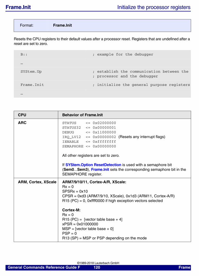
Frame.Init Initialize the processor registers
Resets the CPU registers to their default values after a processor reset. Registers that are undefined after a reset are set to zero.
Format: Frame.Init
B:: ; example for the debugger
…
SYStem.Up ; establish the communication between the; processor and the debugger
Frame.Init ; initialize the general purpose registers
…
CPU Behavior of Frame.Init
ARC STATUS <= 0x02000000STATUS32 <= 0x00000001DEBUG <= 0x11000000IRQ_LV12 <= 0x00000002 (Resets any interrupt flags)IENABLE <= 0xffffffffSEMAPHORE <= 0x00000000
All other registers are set to zero.
If SYStem.Option ResetDetection is used with a semaphore bit (Sem0...Sem3), Frame.Init sets the corresponding semaphore bit in the SEMAPHORE register.
ARM, Cortex, XScale ARM7/9/10/11, Cortex-A/R, XScale:Rx = 0SPSRx = 0x10CPSR = 0xd3 (ARM7/9/10, XScale), 0x1d3 (ARM11, Cortex-A/R)R15 (PC) = 0, 0xffff0000 if high exception vectors selected
Cortex-M:Rx = 0R15 (PC) = [vector table base + 4]xPSR = 0x01000000MSP = [vector table base + 0]PSP = 0R13 (SP) = MSP or PSP depending on the mode
General Commands Reference Guide F 120 Frame ©1989-2018 Lauterbach GmbH

C166 The CP is set to 0xFC00. The sixteen registers R0 - R15 are set to 0x0. DPP0 = 0x0, DPP1 = 0x1, DPP2 = 0x2 and DPP3 = 0x3.Stack registers STKUN is set to 0xFC00 and STKOV is set to 0xFA00.The Stack Pointer SP is set to 0xFC00The Instruction Pointer IP is set to zero.The Code Segment Pointer CSP and the VECSEG are set to the initial value after SYStem.Up.All other registers are set to zero.
CEVA-X MODA and MODA shadow register are set to 0x1E.All other registers are set to zero.
DSP56K Family 56000 and 56100The eight 16-bit modifier registers M[0-7] are set to 0xFFFF. This specifies linear arithmetic as the default type for address register update calculations.The Operating Mode Register (OMR) is set to the initial value after SYStem.Up. Values of bits MA, MB and MC of the OMR register are preserved.The program counter is set to zero. All interrupts are masked by setting the Status Register (SR) to 0x300.
Family 56300 and 56720 DualcoreThe eight 24-bit modifier registers M[0-7] are set to 0xFFFFFF. This specifies linear arithmetic as the default type for address register update calculations. The Operating Mode Register (OMR) is set to the initial value after SYStem.Up. Values of bits MA, MB, MC and MD of the OMR register are preserved. All interrupts are masked by setting Status Register (SR) to 0x300. The program counter is set to zero.
Family 56800 and 56800EThe eight 16-bit modifier registers M[0-7] are set to 0xFFFF. This specifies linear arithmetic as the default type for address register update calculations. The Operating Mode Register (OMR) is set to the initial value after SYStem.Up. Values of bits MA and MB of the OMR register are preserved. All interrupts are masked by setting Status Register (SR) to 0x300. The program counter is set to zero.
HCS08 The Program Counter is set to the value read at 0xFFFE. The Stack Pointer SP is set to 0xFF and the CCR is set to 0x68. All other registers are set to zero.
HC11 The Program Counter is set to the value read at 0xFFFE. The Stack Pointer SP is set to a default value dependent on the derivative. The CCR is set to 0xD8. All other registers are set to zero.
HC12 / S12 / S12X The Program Counter is set to the value read at 0xFFFE. The CCR is set to 0xD8. All other registers are set to zero.
MIPS32 / MIPS64 /NEC-VR
Program Counter, Status register and Config register are set to their initial values after reset (read during SYStem.Up). PRID and Cause register are updated, all other registers are set to zero.
MMDSP Sets all registers to their initial value after a reset. This is done via a soft reset of the core. NOTE: This may have effects besides updating the contents of architectural registers.
CPU Behavior of Frame.Init
General Commands Reference Guide F 121 Frame ©1989-2018 Lauterbach GmbH

See also
■ Frame ■ Frame.view
PowerPC Program counter and MSR are set to their initial values after reset (read during SYStem.Up). GPRs and SPR appearing in the Register window are set to zero.
Microblaze All registers are set to zero.
PCP All registers are set to zero.
Teak MOD0 and MOD0S registers SATA bit is set. MOD1 and MOD1S regsiters CMD bit is set. MOD3 and MOD3S registers CREP, CPC and CCNTA bits are set.All other registers are set to zero.
Teaklite / Teaklite-II /Oak
All registers are set to zero.
Teaklite-III MOD2 register SATA and SATP bits are set.All other registers are set to zero.
x86 EDX is set to a cpu specific value defining the family/model/stepping of the core if a SYStem.Up has been executed at some point before, otherwise EDX is set to 0.EAX,EBX,ECX,ESI,EDI,ESP,EBP are set to 0.EIP is set to 0xFFF0 and EFLAGS to 2.CR0 is set to 0x60000010 and CR2-4 to 0.DR0-3 are set to 0. DR6 to 0xFFFF0FF0 and DR7 to 0x400.IDT and GDT: Base = 0 and Limit = 0xFFFF.LDT and TR: Selector = 0, Base = 0, Limit = 0xFFFF, Access = 0x82.CS: Selector = 0xF000, Base = 0xFFFF0000, Limit = 0xFFFF, Access = 0x93.DS,ES,FS,GS,SS: Selector = 0, Base = 0, Limit = 0xFFFF, Access = 0x93.NOTE: In a multicore system the above holds for the main bootstrap processor. For the other processors the following differences apply: EIP is set to 0x10000 and CR0 to 0x10.
TMS320 All registers except SSR, IER and TSR are set to zero.
TriCore All registers except PC, PSW, ICR and BTV are set to zero.
XTENSA Program Counter (PC), Program Status (PS) and dependent on the XTENSA configuration some other Special Registers are read from the CPU. All other registers are set to zero.
ZSP All registers are set to zero.
CPU Behavior of Frame.Init
General Commands Reference Guide F 122 Frame ©1989-2018 Lauterbach GmbH

Frame.REDO Recover from UNDO registers
Recovers the state of the registers before the last Frame.UNDO command was executed.
See also
■ Frame ■ Frame.view
Frame.SkipFunc Change view to previous/subsequent function
Sets the PC temporarily to one of the subsequent (positive number) or previous (negative number) functions in the source. The current PC value is saved and will be restored before the application is started again.
See also
■ Frame ■ Frame.view
Format: Frame.REDORegister.REDO (deprecated)
Format: Frame.SkipFunc <number>Register.SkipFunc (deprecated)
Frame.SkipFunc -1.
Frame.SkipFunc 1.
General Commands Reference Guide F 123 Frame ©1989-2018 Lauterbach GmbH

Frame.SkipLine Change view to previous/subsequent HLL line
Sets the PC temporarily to one of the subsequent (positive number) or previous (negative number) HLL lines in the source. The current PC value is saved and will be restored before the application is started again.
See also
■ Frame ■ Frame.view
Frame.SWAP Swap TRACE32 registers
The processor register set and TRACE32-internal register sets are swapped. This command is useful when an operating system-call or HLL-function call fails to restore the original registers.
See also
■ Frame ■ Frame.view
▲ ’Register and Peripherals’ in ’ICE User’s Guide’
Frame.TASK Change view to specified task
Display register set of the specified task temporarily. This will also change the source listing display (Data.List).
The register set of the current task is saved and will be restored before the application is started again.
Format: Frame.SkipLine <number>Register.SkipLine (deprecated)
Register.SkipLine +3. ; set PC 3 HLL line forward
Format: Frame.SWAPRegister.SWAP (deprecated)
Format: Frame.TASK <magic_number> | <task_id> | <task_name>Register.TASK (deprecated)
General Commands Reference Guide F 124 Frame ©1989-2018 Lauterbach GmbH

A reddish cursor at the program counter indicates a manipulation by Register.TASK.
See also
■ Frame ■ Frame.view
<magic_number>, <task_id>, <task_name>
For information about the parameters, see “What to know about Magic Numbers, Task IDs and Task Names” (general_ref_t.pdf).
Register.TASK 0x41498 ; <magic_number>
; <task_id>
Register.TASK "thread 0" ; <task_name>
reddish cursor
(task) indicates that theregister set was temporarily changed by the commandRegister.TASK
General Commands Reference Guide F 125 Frame ©1989-2018 Lauterbach GmbH

Frame.UNDO Recover previous registers
Recovers the state of the registers before the last register change or execution command. Repeating the command will recover earlier registers. The command Frame.REDO can be used to “undo” this command.
See also
■ Frame ■ Frame.view
Frame.Up Go up in stack nesting
The debugger “virtually” goes up one level of the call stack by switching to the stack frame of the calling function and reconstructing its registers. The command can be repeated to traverse multiple levels of the call stack. The current offset from the actual stack frame is shown in the status line as (2), (3) etc.
The register window will show the values of the newly selected stack frame. In Data.List windows, the bar indicating the PC position changes its color to a reddish tone to indicate that it is not the actual PC of the processor.
The actual register set in the processor is not affected by this. Therefore a Go would continue from the place where the processor stopped before issuing the Frame.Up command.
The corresponding command for going down in the call hierarchy is Frame.Down.
Format: Frame.UNDORegister.UNDO (deprecated)
Format: Frame.UpRegister.Up (deprecated)
General Commands Reference Guide F 126 Frame ©1989-2018 Lauterbach GmbH

See also
■ Frame ■ Frame.view
reddish cursor
back level
General Commands Reference Guide F 127 Frame ©1989-2018 Lauterbach GmbH

Frame.view Display stack frame[Examples]
Displays a stack back trace. By default the stack frame for the current program context is displayed. The command Frame.CONFIG.Asm configures whether the back trace stops at frames that do not belong to HLL code or attempts to trace back over those frames.
Format: Frame.view [%<format>] [/<option>]Var.Frame (deprecated)
<display_option>:
NoVar | Args | Locals | Caller | MODule | Size | NoSize | LIMIT <levels>
<context_option>:
MACHINE <machine_number> [/VCPU <vcpu_number>]TASK <magic_number> | <task_id> | "<task_name>"CORE <number> | REGSET <number>
A By clicking the little, gray square to the left of a variable, you can switch between the formats hex, decimal, and binary for a value.
B By double-clicking a variable, you can modify its value.
C The numbers in the gray scale area of the Frame.view window indicate the nesting level. Double-clicking a number will execute a Frame.Up command to get to this level.
D Click the +/- toggle button to view the variable in more detail.
<display_option> Without <display_option>, solely the functions together with the arguments are displayed.
<context_option> <context_option> allows to specify a different program context.
<format> The format parameters can modify the display in various ways. For information about format parameters, refer to section “Display Formats” in “General Commands Reference Guide V” (general_ref_v.pdf).
C
B
D
A
General Commands Reference Guide F 128 Frame ©1989-2018 Lauterbach GmbH

Examples:
See also
■ Frame ■ Frame.CONFIG ■ Frame.COPY ■ Frame.Down ■ Frame.GOTO ■ Frame.Init ■ Frame.REDO ■ Frame.SkipFunc ■ Frame.SkipLine ■ Frame.SWAP ■ Frame.TASK ■ Frame.UNDO ■ Frame.Up ■ Var.View ❏ FLAG() ❏ FLAG.READ() ❏ FLAG.WRITE()
▲ ’HLL Structures’ in ’ICE User’s Guide’▲ ’Release Information’ in ’Release History’▲ ’Display Variables’ in ’Training HLL Debugging’
NoVar No display of variables and arguments.
Args Display of arguments (default).
Locals Local variables of functions.
Caller Display of the high level language block, from which the function was called.
MODule Display the module (e.g. library) to which the frame entry belongs.
Size, NoSize Show/hide the frame size.
LIMIT Limit the number of frame levels to be displayed.
TASK Choose a task for which you want to display the frame.For information about the parameters, see “What to know about Magic Numbers, Task IDs and Task Names” (general_ref_t.pdf).
CORE Choose a core for which you want to display the frame.
MACHINE Choose a virtual machine for which you want to display the stack frame. It is possible to specify additionally the number of the vcpu.
REGSET Choose one of the switchable register sets.
; display stack frame for task1 on the virtual machine 2Frame.view /MACHINE 2 /TASK "task1"
; display stack frame with call information and local variablesFrame.view /Caller /Locals
General Commands Reference Guide F 129 Frame ©1989-2018 Lauterbach GmbH

FXU
FXU FXU registers (extended floating point unit)RH850
See also
■ FXU.Init ■ FXU.Set ■ FXU.view
▲ ’FXU Function’ in ’General Functions’
FXU.Init Initialize FXU registersRH850
Sets all registers of the active FXU extension to zero.
See also
■ FXU ■ FXU.view
FXU.Set Modify FXU registersRH850
Modifies the FXU registers.
See also
■ FXU ■ FXU.view
Format: FXU.Init
Format: FXU.Set <register> <value> …
General Commands Reference Guide F 130 FXU ©1989-2018 Lauterbach GmbH

FXU.view Open FXU register windowRH850
Opens an FXU register window.
See also
■ FXU ■ FXU.Init ■ FXU.Set
Format: FXU.view
General Commands Reference Guide F 131 FXU ©1989-2018 Lauterbach GmbH

![AT Reference Guide - Multi-Tech Systems, Inc.€¦ · DE910- Series AT commands reference guide – AT commands [...]](https://static.fdocuments.in/doc/165x107/6062516d02f817666972114c/at-reference-guide-multi-tech-systems-inc-de910-series-at-commands-reference.jpg)