
General catalogue series
70
Commercial Vehicles General catalogue series Today, our Cardan 2000 Compact line represents a largely standardized selection of universal shafts suitable for a wide variety of vehicles and models. In developing these products we were able to anticipate a number of important trends in the field of commercial vehicle design. Major features of the Cardan shaft include its high resistance to dynamic load variations, large deflection angles, uniform load distribution throughout the axial displacement range, low rotational diameter, low weight, and versatile flange connections. These features provide an ideal base for standardised drive train design and new power transmission concepts.
Transcript of General catalogue series

Commercial Vehicles
General catalogue series
Today, our Cardan 2000 Compact line represents a largely standardized selection of universal shafts suitable for a wide variety of vehicles and models. In developing these products we were able to anticipate a number of important trends in the field of commercial vehicle design. Major features of the Cardan shaft include its high
resistance to dynamic load variations, large deflection angles, uniform load distribution throughout the axial displacement range, low rotational diameter, low weight, and versatile flange connections. These features provide an ideal base for
standardised drive train design and new power transmission concepts.

2/70
Index 3 General trends in commercial vehicle development 5 Product description 6 Main features 7 Cardan shafts in detail - Joints - Unit pack - Sliding joint - Centre bearing 8 Variants of connections 9 Number of flange variants 10 Cardan shafts variants and combinations 11 Survey of sizes 12 Data Sheets 12 Cardan shaft with length compensation 13 Cardan shaft without length compensation with midship 14 Shaft assembly with length compensation in midship bearing area 15 Short coupled cardan shaft with length compensation (Sleeve-Yoke-Design) 16 Short coupled cardan shaft with length compensation (Sleeve-Muff-Design) 17 Cardan shaft with length compensation and centered double joint on both sides Version 0.06 18 Cardan shaft with length compensation and centered double joint on one side Version 0.08 19 Flange fittings 19 - X-Serration Flange fittings (XS) 20 - Flange fittings (DIN) 21 - Flange fittings (SAE) 22 Centre bearing 23 General fundamental theory 23 Kinematics of Hooke's joints 27 General technical terms of propshaft application 28 Directions for inquiries and orders 67 - Technical Questionnaire 29 Installation and Maintenace 29 Installation conditions 34 Influence of speed and deflection angle 37 Load on connection bearings 41 - Calculation scheme 42 Length dimensions 43 - Arrangements of cardan shafts 44 Balancing of cardan shafts 45 Flange boltings 47 Safety instructions 48 Transport and storage 50 Installation/disassembly 51 - Installations of drive lines 52 - Disassembly 53 - Companion flanges 56 Maintenance 56 - Maintenance intervals 57 - Scope of maintenance 60 - Lubrication 61 - Recommended regreasing intervals 62 Repair 63 Reconditioning of Cardan Shafts 64 After-sales service 69 Alphabetic Index
3/70
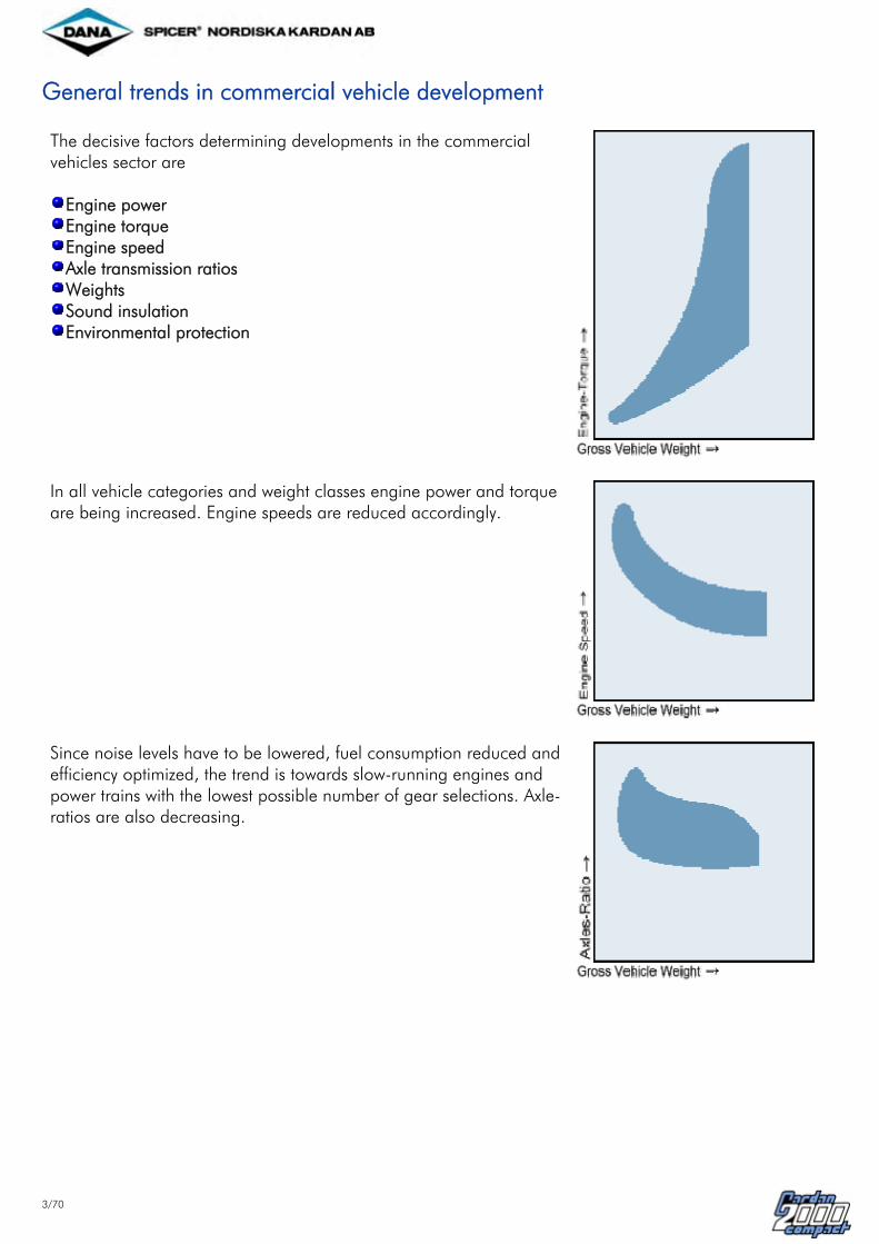
General trends in commercial vehicle development The decisive factors determining developments in the commercial vehicles sector are
Engine power Engine torque Engine speed Axle transmission ratios Weights Sound insulation Environmental protection
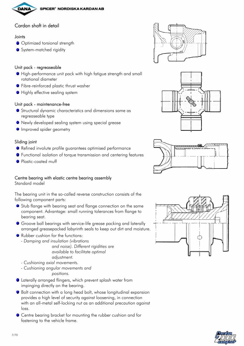
In all vehicle categories and weight classes engine power and torque are being increased. Engine speeds are reduced accordingly.
Since noise levels have to be lowered, fuel consumption reduced and efficiency optimized, the trend is towards slow-running engines and power trains with the lowest possible number of gear selections. Axle-ratios are also decreasing.

4/70
Over the recent years vehicle unladen weights have decreased across the board, permitting higher maximum pay loads. In addition, new legislation has permitted higher axle loads and higher total loads of tractor/trailer rigs.
Keeping pace with these trends, we have tailored the design and dimensioning of the new Compact 2000 cardan shaft series to the specific requirements of the market.

5/70
Product description
The Compact 2000 range is available in 12 sizes and torque capacities.
Functional Limit Torque TCS (Torque capacity static)
is the torsional stress to which the cardan shaft can be loaded without loss of operational capability. Other key parameters:
Swing diameter Weights Speed limits
We can supply the right cardan shaft size across the entire commercial vehicle spectrum.

6/70
Main features Using optimizing engineering, the Compact 2000 cardan shaft series has been designed to meet the requirements of commercial vehicle manufactures such as: Capacity
Transmission of static torque Resistance to alternating and pulsating stresses
Bearing life
Well matched dynamic and static loadbearing capacity Dynamic behaviour
Reduced mass moment of inertia Longer single-piece cardan shaft for given speed Reduced unbalance through lowered shaft weight Enhanced true running due to new centre bearing design Improved/repeatable balance due to accurate
centering of cross-serration Operating Temperature
Cardan shafts are available as standard or special types for various operating temperature ranges:
Version Temperature range
High temperature (shortly)
Standard - 25 °C to + 60 °C 80 °C
High temp. - 25 °C to + 80 °C 120 °C
Low temp. - 50 °C to + 60 °C 80 °C
Weight
Weight reduced for given static and dynamic torque Short design
Reduced installation length due to use of standardized components Expansion of the short coupling range through addition of particularly short versions
Logistics
Conformity with international standards (ISO) Reduction of complexity Use of cross-serration flanges to provide
- cost-efficient stocking - fewer bolts to fix - bolt fixing simplified - shorter assembly time
Protection of environment
Reduced noise emission Maintenance-free versions application of grease free of lead
7/70
Cardan shaft in detail Joints
Optimized torsional strength
System-matched rigidity
Unit pack - regreaseable
High-performance unit pack with high fatigue strength and small rotational diameter
Fibre-reinforced plastic thrust washer
Highly effective sealing system Unit pack - maintenance-free
Structural dynamic characteristics and dimensions same as regreaseable type
Newly developed sealing system using special grease
Improved spider geometry
Sliding joint
Refined involute profile guarantees optimised performance
Functional isolation of torque transmission and centering features
Plastic-coated muff
Centre bearing with elastic centre bearing assembly Standard model The bearing unit in the so-called reverse construction consists of the following component parts:
Stub flange with bearing seat and flange connection on the same component. Advantage: small running tolerances from flange to bearing seat.
Groove ball bearings with service-life grease packing and laterally arranged greasepacked labyrinth seals to keep out dirt and moisture.
Rubber cushion for the functions: - Damping and insulation (vibrations
and noise). Different rigidities are available to facilitate optimal adjustment.
- Cushioning axial movements. - Cushioning angular movements and
positions.
Laterally arranged flingers, which prevent splash water from impinging directly on the bearing.
Bolt connection with a long head bolt, whose longitudinal expansion provides a high level of security against loosening, in connection with an all-metal self-locking nut as an additional precaution against loss.
Centre bearing bracket for mounting the rubber cushion and for fastening to the vehicle frame.

8/70
Variants of connections Attaching cardan shafts to various transmissions and axle assemblies calls for different types of connections. The following flange types (ISO standard) are available:
XS
Positive engagement - XS (x-serration), corresponding to
ISO 8667 for gearbox flanges ISO 12667 for propeller shaft flanges
Friction type - to DIN, corresponding to ISO 7646 - to SAE, corresponding to ISO 7647
DIN
SAE The x-serration flange (XS) is gaining ever wider acceptance on account of its technical and economical advantages and is set to become the preferred flange of the future. The advantages are:
Positive engagement of serrations Shorter time required for assembly Bolting simplified Fewer bolts Reduced stock complexity Clearly defined mounting position Use of self-locking nuts

9/70
Number of flange variants
10 DIN-Flanges 4 XS-Flanges ISO 12667 12 SAE-Flanges

10/70
Cardan shaft variants and combinations
The main variants are:
Cardan shaft with length compensation (fixed and slip)
Cardan shaft without length compensation with midship (fixed and mid)
Short coupled cardan shaft with length compensation variants with sleeve yoke/sleeve muff
The design of the cardan shaft line may vary according to application, e.g.
Shaft assembly with fixed-length midship shaft and cardan shaft with length compensation
Shaft assembly with length compensation in midship bearing area
Additional variants on request.
Special variants- e.g.: maintenance free, higher/lower temperature, sound insulated construction etc. on request.
11/70
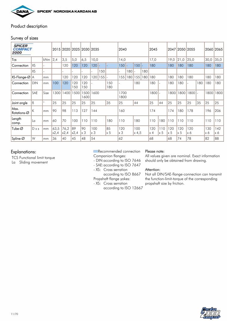
Product description Survey of sizes
2015 2020 2025 2030 2035 2040 2045 2047 2050 2055 2060 2065
Tcs kNm 2,4 3,5 5,0 6,5 10,0 14,0 17,0 19,0 21,0 25,0 30,0 35,0
Connection XS - 120 120 120 120 - - 150 - 150 - 180 180 180 180 180 180
XS - - - - - 150 - 180 - 180 XS-Flange-Ø A mm 120 120 120 120 155 - 155 180 155 180 180 180 180 180 180 180
Connection DIN mm 100 120 120 150
120 150
- 150 180
- 180 180 - 180 180 - 180 180 180
Connection SAE Size 1300 1400 1500 1500 1600
1600 1700 1800
1800 - 1800 1800 1800 - 1800 1800
Joint angle ß ° 25 25 25 25 25 35 25 44 25 44 25 25 25 35 25 25
Max. Rotations-Ø
K mm 90 98 113 127 144 160 174 174 180 178 196 206
Length comp.
La mm 60 70 100 110 110 180 110 180 110 180 110 110 110 110 110
Tube-Ø D x s mm 63,5 x2,4
76,2x2,4
89 x2,4
90 x 3
100 x 3
85 x 5
120 x 3
100 x 4,5
120x 4
110 x 5
120 x 5
120 x 5
120 x 6
130x 6
142x 6
Spline-Ø W mm 36 40 45 48 54 62 68 68 74 78 82 88
Explanations: TCS La
Functional limit torque Sliding movement
Recommended connection Companion flanges: - DIN:- SAE:- XS:
according to ISO 7646according to ISO 7647Cross serration according to ISO 8667
Propshaft flange yokes: - XS: Cross serration
according to ISO 12667
Please note: All values given are nominal. Exact information should only be obtained from drawing. Attention: Not all DIN/SAE-flange-connection can transmit the function-limit-torque of the corresponding propshaft size by friction.

12/70
Data Sheets Standard variants Cardan shaft with length compensation
2015 2020 2025 2030 2035 2040 2045 2047 2050 2055 2060 2065
Tcs kNm 2,4 3,5 5,0 6,5 10,0 14,0 17,0 19,0 21,0 25,0 30,0 35,0
Connection - DIN 100 DIN 120 XS 120 XS 120 XS 150 XS 180 XS 180 XS 180 XS 180 XS 180 XS 180 XS 180
Flange-Ø A mm 100 120 120 120 120 155 155 180 180 180 180 180 180 180
Joint angle ß ° 25 25 25 25 25 35 25 44 25 44 25 25 25 25 25
Max. Rotations-Ø
K mm 90 98 113 127 144 160 174 174 180 178 196 206
M mm 48 54 60 63,5 75 88 82 102 87 108 87 85 92 100 105
Lzmin mm 346 379 438 475 542 667 546 693 579 729 579 576 616 635 676
La mm 60 70 100 110 110 180 110 180 110 180 110 110 110 110 110
Tube-Ø D x s mm 63,5x 2,4 76,2x 2,4 89x 2,4 90x 3 100x 3 85x 5 120x 3 100x4,5 120x 4 110x 5 120x 5 120x 5 120x 6 130x 6 142x 6
GW kg 8,0 11,2 15,0 18,0 23,7 27,0 33,3 38,8 43,0 46,0 43,0 46,4 51,7 60,5 70,6
GR kg 3,6 4,4 5,1 6,4 7,17 9,9 8,65 10,6 11,44 12,9 14,18 14,18 16,86 18,34 20,12
Spline-Ø W mm 36 40 45 48 54 62 68 68 74 78 82 88 Explanations: TCS Lz La GW GR
Functional limit torque Compressed length Sliding movement Weight of 1 m-shaft Weight of 1 m-tube
Recommended connection Companion flanges: - DIN:- SAE:- XS:
according to ISO 7646according to ISO 7647Cross serration according to ISO 8667
Propshaft flange yokes: - XS: Cross serration
according to ISO 12667
Please note: All values given are nominal. Exact information should only be obtained from drawing. Attention: Not all DIN/SAE-flange-connection can transmit the function-limit-torque of the corresponding propshaft size by friction.
13/70
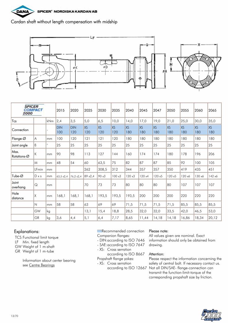
Cardan shaft without length compensation with midship
2015 2020 2025 2030 2035 2040 2045 2047 2050 2055 2060 2065
Tcs kNm 2,4 3,5 5,0 6,5 10,0 14,0 17,0 19,0 21,0 25,0 30,0 35,0
Connection - DIN 100
DIN 120
XS 120
XS 120
XS 120
XS 180
XS 180
XS 180
XS 180
XS 180
XS 180
XS 180
Flange-Ø A mm 100 120 121 121 120 180 180 180 180 180 180 180
Joint angle ß ° 25 25 25 25 25 25 25 25 25 25 25 25
Max. Rotations-Ø
K mm 90 98 113 127 144 160 174 174 180 178 196 206
M mm 48 54 60 63,5 75 82 87 87 85 92 100 105
LFmin mm 262 308,5 312 344 357 357 350 419 435 451
Tube-Ø D x s mm 63,5 x2,4 76,2 x2,4 89 x2,4 90 x3 100 x3 120 x3 120 x4 120 x5 120 x5 120 x6 130 x6 142 x6
Joint overhang
Q mm 70 73 73 80 80 80 80 107 107 107
Hole distance
X mm 168,1 168,1 168,1 193,5 193,5 193,5 200 200 200 220 220 220
N mm 58 58 63 69 69 71,5 71,5 71,5 71,5 85,5 85,5 85,5
GW kg 13,1 15,4 18,8 28,5 32,0 32,0 33,5 42,0 46,5 53,0
GR kg 3,6 4,4 5,1 6,4 7,17 8,65 11,44 14,18 14,18 16,86 18,34 20,12
Explanations: TCS LF GW GR
Functional limit torque Min. fixed length Weight of 1 m-shaft Weight of 1 m-tube Information about center bearing see Centre Bearings
Recommended connection Companion flanges: - DIN:- SAE:- XS:
according to ISO 7646according to ISO 7647Cross serration according to ISO 8667
Propshaft flange yokes: - XS: Cross serration
according to ISO 12667
Please note: All values given are nominal. Exact information should only be obtained from drawing. Attention: Please respect the information concerning the safety of central bolt. If necessary contact us. Not all DIN/SAE- flange-connection can transmit the function-limit-torque of the corresponding propshaft size by friction.

14/70
Shaft assembly with length compensation in midship bearing area
2015 2020 2025 2030 2035 2040 2045 2055
Tcs kNm 2,4 3,5 5,0 6,5 10,0 14,0 17,0 25,0
Connection SAE 1400 XS 120 XS 120 XS 120 XS 120 XS 150 XS 180 XS 180
Flange-Ø A mm 99 120 120 120 120 150 180 180
max. Joint angle ß ° 25 25 25 25 25 25 25 25
Joint angle ß ° 6 6 6 6 6 6 6 6
Max. Rotations-Ø
K mm 90 98 113 127 144 160 174 178
M mm 43 54 60 63,5 75 82 87 92
Lz min. mm 807 874 913 892
L1 min. mm 262 276 313 347,5 347 372 385 382
La mm 90 90 100 110 80 80 80 80
Tube 1 D1 x S1 mm 76,2 x 1,64 76,2 x 2,4 89 x 2,4 90 x 3 85 x 5 100 x 4,5 110 x 5 120 x 6
Tube 2 D2 x S2 mm 76,2 x 1,64 76,2 x 2,4 89 x 2,4 90 x 3 100 x 3 120 x 3 120 x 4 120 x 6
Joint overhang Q min. mm 75 78 86 88 99 201 207 218
Hole distance X mm 168,1 168,1 168,3 193,5 220 220 220 220
N mm 58 58 62,8 69 85 85 85 85
Hole-Ø d mm 13,5 13,5 13 13 15 15 15 15
GR1 kg 9,9 10,6 12,9 16,8
GR2 kg 7,17 8,65 11,44 16,8
Spline-Ø W mm 54 62 68 78
Explanations: TCS Lz min. L1 min. La GR1 GR2
Functional limit torque Compressed length Min. length Length compensation Weight of Tube 1 (Tubelength 1 m) Weight of Tube 2 (Tubelength 1 m)
Recommended connection Companion flanges: - DIN:- SAE:- XS:
according to ISO 7646according to ISO 7647Cross serration according to ISO 8667
Propshaft flange yokes: - XS: Cross serration
according to ISO 12667
Please note: All values given are nominal. Exact information should only be obtained from drawing. Attention: Not all DIN/SAE-flange-connection can transmit the function-limit-torque of the corresponding propshaft size by friction.

15/70
Short coupled cardan shaft with length compensation Sleeve-Yoke-Design
2015 2020 2025 2030 2035 2040 2045 2055 2065
Tcs kNm 2,4 3,5 5,0 6,5 10,0 14,0 17,0 25,0 35,0
Connection - DIN 100
DIN 120
XS 120 XS 120 XS 120 XS 150 XS 180 XS 180 XS 180
Flange-Ø A mm 100 120 120 120 120 155 180 180 180
Joint angle ß ° 25 25 25 25 25 25 25 25 25
Max. Rotations-Ø
K mm 90 98 113 127 144 160 174 178 206
M mm 48 54 60 63,5 75 82 87 92 105
Lz max. mm 280 317 335 380 444 466 491 517 574
La max. mm 60 70 70 95 110 110 110 110 110
GW max. kg 25,1 33 41
Lz min. mm 245 274 293 314 379 401 431 467 514
La min. mm 25 27 28 29 45 45 50 50 50
GW min. kg 22,5 30,1 38,2
Spline-Ø W mm 36 40 45 48 54 62 68 78 88
Explanations: TCS Lz max. La max. Lz min. La min. GW
Functional limit torque Compressed length with max. length compression Max. length compensation Compressed length with min. length compression Min. length compensation Weight of short coupled cardan shaft with Lc min. / Lc max.
Recommended connection Companion flanges: - DIN:- SAE:- XS:
according to ISO 7646according to ISO 7647Cross serration according to ISO 8667
Propshaft flange yokes: - XS: Cross serration
according to ISO 12667
Please note: All values given are nominal. Exact information should only be obtained from drawing. Attention: Not all DIN/SAE-flange-connection can transmit the function-limit-torque of the corresponding propshaft size by friction.

16/70
Short coupled cardan shaft with length compensation Sleeve-Muff-Design
2015 2020 2025 2030 2035 2040 2045 2050 2055 2060 2065
Tcs kNm 2,4 3,5 5,0 6,5 10,0 14,0 17,0 21,0, 25,0 30,0 35,0
Connection - DIN 100
DIN 120
XS 120
XS 120 XS 120 XS 150 XS 180 XS 180 XS 180 XS 180 XS 180
Flange-Ø A mm 100 120 120 120 120 155 180 180 180 180 180
Joint angle ß ° 25 25 25 25 25 25 25 25 25 25 25
Max. Rotations-Ø
K mm 90 98 113 127 144 160 174 180 178 196 206
M mm 48 54 60 63,5 75 82 87 85 92 100 105
Lz max. mm 348 381 405 436 510 505 541 531 571 590 631
La max. mm 90 100 100 110 110 110 110 110 100 110 110
GWmax. kg 20,9 26,4 35,3 39,5 43 50,8 61,1
Lz min. mm 296 322 341 362 470 465 501 491 531 550 591
La min. mm 38 41 36 36 70 70 70 70 70 70 70
GWmin. kg 19,3 24,8 33,3 37,1 40,2 48,4 57,9
Spline-Ø W mm 36 40 45 48 54 62 68 74 78 82 88
Explanations: TCS Lz max. La max. Lz min. La min. GW
Functional limit torque Compressed length with max. length compression Max. length compensation Compressed length with min. length compression Min. length compensation Weight of short coupled cardan shaft with Lc min. / Lc max.
Recommended connection Companion flanges: - DIN:- SAE:- XS:
according to ISO 7646according to ISO 7647Cross serration according to ISO 8667
Propshaft flange yokes: - XS: Cross serration
according to ISO 12667
Please note: All values given are nominal. Exact information should only be obtained from drawing. Attention: Not all DIN/SAE-flange-connection can transmit the function-limit-torque of the corresponding propshaft size by friction.
17/70
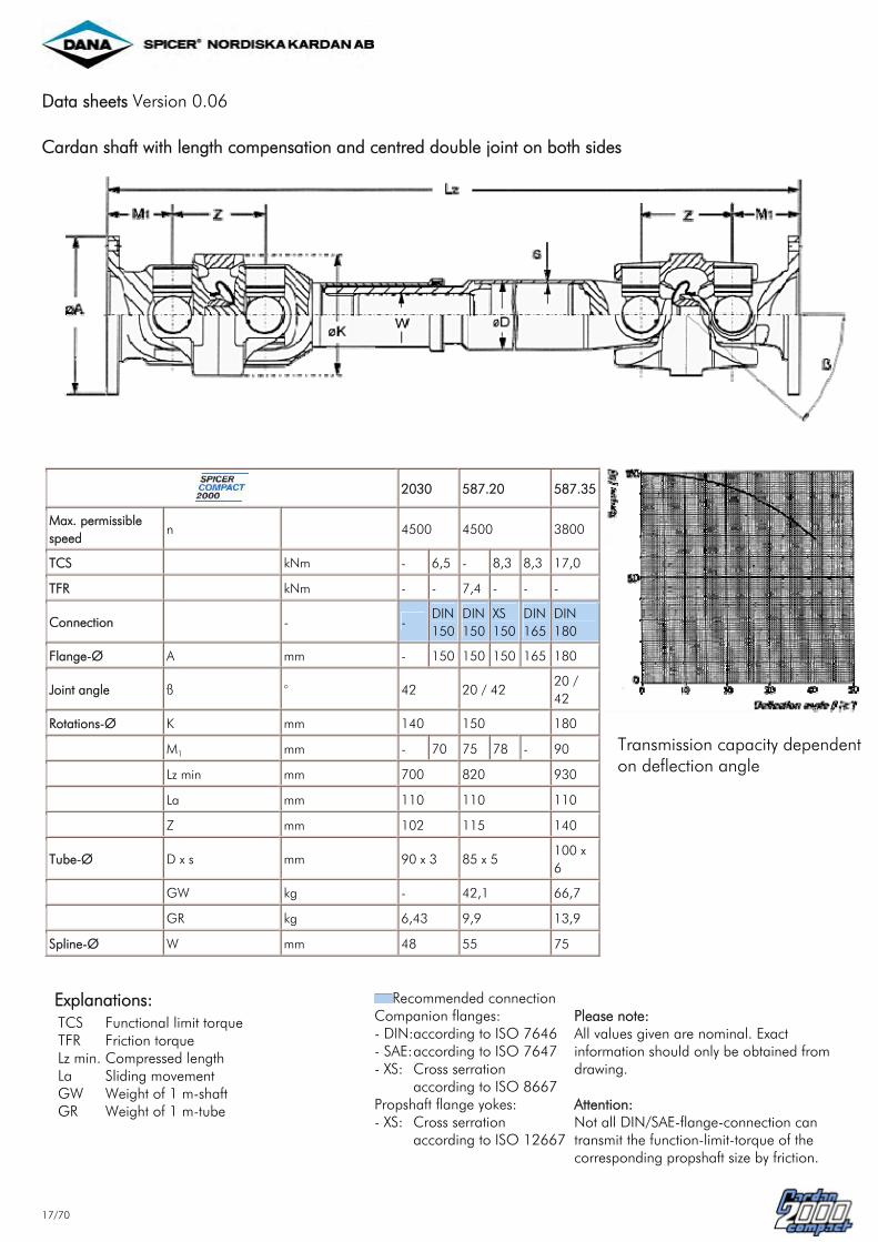
Data sheets Version 0.06 Cardan shaft with length compensation and centred double joint on both sides
2030 587.20 587.35
Max. permissible speed
n 4500 4500 3800
TCS kNm - 6,5 - 8,3 8,3 17,0
TFR kNm - - 7,4 - - -
Connection - - DIN 150
DIN 150
XS 150
DIN 165
DIN 180
Flange-Ø A mm - 150 150 150 165 180
Joint angle ß ° 42 20 / 42 20 / 42
Rotations-Ø K mm 140 150 180
M1 mm - 70 75 78 - 90
Lz min mm 700 820 930
La mm 110 110 110
Z mm 102 115 140
Tube-Ø D x s mm 90 x 3 85 x 5 100 x 6
GW kg - 42,1 66,7
GR kg 6,43 9,9 13,9
Spline-Ø W mm 48 55 75
Transmission capacity dependent on deflection angle
Explanations: TCS TFR Lz min. La GW GR
Functional limit torque Friction torque Compressed length Sliding movement Weight of 1 m-shaft Weight of 1 m-tube
Recommended connection Companion flanges: - DIN:- SAE:- XS:
according to ISO 7646according to ISO 7647Cross serration according to ISO 8667
Propshaft flange yokes: - XS: Cross serration
according to ISO 12667
Please note: All values given are nominal. Exact information should only be obtained from drawing. Attention: Not all DIN/SAE-flange-connection can transmit the function-limit-torque of the corresponding propshaft size by friction.

18/70
Data sheets Version 0.08
Cardan shaft with length compensation and centered double joint on one side
2030 587.20 587.35
Max. permissible speed
n 4500 4500 3800
TCS kNm - 6,5 - 8,3 8,3 17,0
TFR kNm - - 7,4 - - -
Connection - - DIN 150
DIN 150
XS 150
DIN 165
DIN 180
Flange-Ø A mm - 150 150 150 165 180
Joint angle ß ° 42 20 / 42 20 / 42
Joint angle ß1 ° 25 35 35
Rotations-Ø K mm 140 150 180
M mm - 63,5 75 75 86 100
M1 mm - 70 75 78 - 90
Lz min mm 600 705 820
La mm 110 110 110
Z mm 102 115 140
Tube-Ø D x s mm 90 x 3 85 x 5 100 x 6
GW kg - 34,5 66,9
GR kg 6,43 9,9 13,9
Spline-Ø W mm 48 55 75
Transmission capacity dependent on deflection angle
Explanations: TCS TFR Lz min. La GW GR
Functional limit torque Friction torque Compressed length Sliding movement Weight of 1 m-shaft Weight of 1 m-tube
Recommended connection Companion flanges: - DIN:- SAE:- XS:
according to ISO 7646according to ISO 7647Cross serration according to ISO 8667
Propshaft flange yokes: - XS: Cross serration
according to ISO 12667
Please note: All values given are nominal. Exact information should only be obtained from drawing. Attention: Not all DIN/SAE-flange-connection can transmit the function-limit-torque of the corresponding propshaft size by friction.

19/70
Flange fittings
X-Serration flange fittings (XS)
2020 2025 2030 2035 2040
2045 2047
2050 2055 2060 2065
Tcs kNm 3,5 5,0 6,5 10,0 14,0 17,0 19,0 (at 2047)
21,0 25,0 30,0 35,0
Connection XS - 120 120 120 120 150 150 150 180 180 180 180 180 180 Flange-Ø A mm 120* 120* 120* 120* 155** 155** 155** 180 180 180 180 180 180
Joint angle ß ° 25 25 25 25 35 25 44 25 44 25 25 25 25
M mm 54 60 63,5 75 88 82 102 87 108 85 92 100 105
B mm 100 100 100 100 130 130 130 150 150 150 150 150 150
I x H 4 x 11 4 x 11 4 x 11 4 x 11 4 x 13 4 x 13 4 x 13 4 x 15 4 x 15 4 x 15 4 x 15 4 x 15 4 x 15 Flange-Ø A mm 155** 155** 180 180 155** 180 180 Joint angle ß ° 25 25 25 44 37 35 35
M mm 65 75 82 102 100 95 102
B mm 130 130 150 150 130 150 150
I x H 4 x 13 4 x 13 4 x 15 4 x 15 4 x 13 4 x 15 4 x 15
Explanations: TCS I x H
Functional limit torque Threaded hole diameter andnumber of bores Preferred range
* Flange-Ø 122 mm available in addition ** Flange-Ø 152 mm available in addition Companion flanges: - according to ISO 8667 Propshaft flange yokes: - according to ISO 12667
Please note: All values given are nominal. Exact information should only be obtained from drawing.

20/70
Flange fittings (DIN)
2015 2020 2025 2030 2035 2040 2045 2047 2050 2055 2060 2065
Tcs kNm - 3,5 5,0 6,5 - - 17,0 19,0 - - - 35,0
TFR kNm 1,5 - - - 7,4 12,1 - - 20,5 20,5 - 20,5
Flange-Ø A mm 100 120 150 150 150 180 180 180 180 180 - 180
Joint angle ß ° 25 25 25 35 35 44 35 35 35 35 - 35
M mm 48 54 60 78 95 102 95 95 100 115 - 110
B mm 84 101,5 130 130 130 155,5 155,5 155,5 155,5 155,5 - 155,5
C mm 57 75 90 90 90 110 110 110 110 110 - 110
F mm 2,5 2,5 3,0 3,0 3,0 3,0 3,0 3,0 3,0 3,0 - 3,0
G mm 7 8 10 10 10 12 12 12 12 14 - 15
I x H 6 x 8,25
8 x 10,25
8 x 12,25
8 x 12,25
8 x 12,1
8 x 14,1 10 x 16,1
10 x 16,1
10 x 16,1
10 x 16,1
- 10 x16,1
TFR kNm 3,9 3,9 10,0 7,4 14,0 14,8 14,8 Flange-Ø A mm 120 120 180 150 165 165 165 Joint angle ß ° 35 35 35 44 35 44 44
M mm 70 72 90 102 90 112 112
B mm 101,5 101,5 155,5 130 140 140 140
C mm 75 75 110 90 95 95 95
F mm 2,5 2,5 3,0 3,0 3,0 3,0 3,0
G mm 8 10 12 10 12 12 12
I x H 8 x 10,25
8 x 10,25
8 x 14,1
8 x 12,1
8 x 16,1
8 x 16,1
8 x 16,1
Explanation: TCS TFR I x H
Functional limit torque Friction torque Threaded hole diameter andnumber of bores
Preferred range Companion flanges: - according to ISO 7646
Please note: All values given are nominal. Exact information should be obtained from drawing.

21/70
Flange fittings (SAE)
2015 2020 2025 2030 2035 2040
2045 2047
2050 2055 2060 2065
TFR kNm 1,5 2,7 4,6 5,9 5,9 10,6 10,6 10,6 10,6 10,6 15,6
Connection SAE Size 1300 1400 1500 1600 1600 1800 1800 1800 1800 1800 1800
Flange-Ø A mm 96,8 115,9 151 174,6 174,6 203,2 203,2 203,2 203,2 203,2 203,2
Joint angle ß ° 25 25 25 25 35 25 25 25 25 25 25
M mm 43 48 60 60 88 70,5 86 76,5 92 92 110
B mm 79,37 95,27 120 155,6 155,6 184,15 184,15 184,15 184,15 184,15 184,15
C mm 60,32 69,85 95,25 168,2 168,2 196,8 196,8 196,8 196,8 196,8 196,8
F mm 1,4 1,4 1,6 3,0 3,0 3,0 3,0 3,0 3,0 3,0 3,0
G mm 7 8 10 9,5 9,5 9,5 11 11 11 11 14
I x H 4 x 10,25 4 x 12,25 4 x 14,25 8 x 10,1 8 x 10,1 12 x 10,1 12 x 10,1 12 x 10,1 12 x 10,1 12 x 10,1 12 x 12,1
TFR kNm 3,6 14 10,6 12,4 12,4 10,6 12,4 12,4
Connection SAE Size 1510 1800 1800 1800 1800 1800 1800 1800
Flange-Ø A mm 146 203,2 203,2 203,2 203,2 203,2 203,2 203,2
Joint angle ß ° 25 44 44 25 25 35 25 25
M mm 60 100 100 86 76,5 95 92 92
B mm 120 184,2 184,2 184,15 184,2 184,2 184,2 184,2
C mm 95,25 196,8 196,8 196,8 196,8 196,8 196,8 196,8
F mm 1,6 3 3 3 3 3 3 3
G mm 10 9,5 9,5 11 11 11 11 11
I x H 4 x 12,25 12 x 12,1 12 x 10,1 12 x 11,1 12 x 11,1 12 x 10,1 12 x 11,1 12 x 11,1
Explanations: TFR I x H
Friction torque Threaded hole diameter and number of bores
Preferred range Companion flanges: - according to ISO 7647
Please note: All values given are nominal. Exact information should only be obtained from drawing.

22/70
Centre bearing
2015 2020 2025 2030 2035 2040 2045 2047 2050 2055 2060 2065
Bearing-Ø T mm 45 45 40 45 45 55 55 55 55 70 70 70
Variant II II I I I I I I I I I I
Hole-Ø1) d mm - - 12,7 - - - 15 15 15 15 15 15
Hole length1) V1+V2 mm 13,5 x 18 13,5 x 18 14,5 x 13 14,5 x 13 14,5 x 13 14,5 x 16 15 x 30 15 x 30 15 x 30 15 x 30 15 x 30 15 x 30
Hole distance X mm 168,1 168,1 168,1 193,5 193,5 193,5 200 200 200 220 220 220
Flange thickness t mm 6,5 6,5 4 4,8 4,8 4,8 4,8 4,8 4,8 5,8 5,8 5,8
Flange distance N mm 58 58 63 69 69 71,5 71,5 71,5 71,5 85,8 85,8 85,8
Flange-Ø A mm - - 120 120 155 180 180 180 180 180 180 180 XS
Q mm - - 70 73 73 80 80 80 80 107 107 107
Flange-Ø A mm 180 180 180 DIN
Q mm 107 107 107
Connection Size 1300 1400 1600
Flange-Ø A mm 96,8 115,9 174,5 SAE
Q mm 78 78 89
Explanations: T 1)
Midship bearing diameter Alternative long hole or round hole
Selection of midship see Cardan shaft without length compensation with midship.
Please note: All value given are nominal. Exact information should only be obtained from drawing. Attention: Upon installation a stable centre bearing support should be enshured. (See Installations of drive lines). Please respsct this information concerning the safety of central bolt. If necessary contact us.

23/70
General fundamental theory Kinematics of Hooke's joints 1. The joints In the theory of mechanics the cardan joint or Hooke's joint is defined as a spatial or spherical drive unit with a non-uni form gear ratio or transmission. The transmission behaviour of this joint is described by the equation.
In this equation the momentary rotation angle of the driven shaft 2. The motion behaviour of the driving and the driven ends is shown in the following diagram. The asynchronous and / or non-homokinematic running of the shaft 2 is shown in the periodical oscilation of the asynchronous line round the synchronous line (dotted line).
A measure for the non-uniformity is the difference of the rotation angles and or the transmission ratio of the angular speeds and .

24/70
Expressed by an equation, that means:
a) rotation angle difference
(also called gimbal error)
b) Gear ratio
The following diagram shows the gear ratio i = / for a full revolution of the universal joint for ß = 60°.
The degree of non-uniformity U is defined by:
U = i max. - i min. = tan ß * sin ß where:

25/70
The diagram shows the course of the degree of nonuniformity U and of the angular difference as a function of the deflection angle of the joint from 0 to 45°. From the motion equation it is evident that a homokinematic motion behaviour corresponding to the dotted line under 45° - as shown in the diagram - can only be obtained for the deflection angle ß = 0°. A synchronous or homokinematic running can be achieved by a suitable combination or connection of two or more joints.

26/70
2. The universal shaft The rotation angle difference or the gimbal error of a deflected universal joint can be offset under certain installation conditions with a second universal joint. The constructive solutions are the following: 1) The deflection angles of both joints must be equal, i.e.
Two arrangements are possible:
2) The two joints must have a kinematic angular relationship of 90° ( / 2), i.e. the yokes of the connecting shaft are in one plane. For a more intensive study of universal shaft kinematics we refer you to the VDI-recommendation 2722 to the relevant technical literature and especially to the book ,,Kardangelenkgetriebe und ihre Anwendung" (Cardan joint drives and their application) by Florian Duditza, published by VDI.

27/70
General technical terms of propshaft application For the application of propshafts of the series Compact 2000 a special calculation method and software has been developed. This calculation method is based on general physical terms and additional experiences of real vehicel measurements. The fundamental items of the "VAMP-method" (Vehicle Application Method for Propshafts) reflect to:
vehicle parameters operating conditions characteristical values of Compact 2000 propshafts special customer requirements
According to these the following parameters are checked:
• Fatigue Strength Criteria for fatigue strength is the maximum generated torque in the driveline under normal operating conditions. lt is determined by:
a) the maximum driving torque
b) the maximum adhesion torque
• In relation to the relevant criterion the size of propshaft with the sufficient static capacity Tcs is determined. Up to this torque limit a shaft can be loaded without disturbing the function of the driveline.
• Structural Strength The structural strength is based on the maximum torque which can occure under extreme conditions or misuse. Limitations which refer to the adhesion torque are also taken into account.
• Lifetime of a Unit Pack The lifetime of a unit pack is calculated by use of specific load distributions from the customer or parameters of general inhouse measurements and experiences.
• Speed, Working Angle, Length Criteria are:
- the relation of the maximum speed during - the excitation of torsional vibrations genera-ted by propshaft speed and
working angle Finally the optimal propshaft size will be recom-mended. To identify specific characteristical values of e.g. special dynamic behaviour of drivelines we can support the customers with simulation calculations and vehicle measurements.
28/70
Please contact our application experts for these and aIl other items.
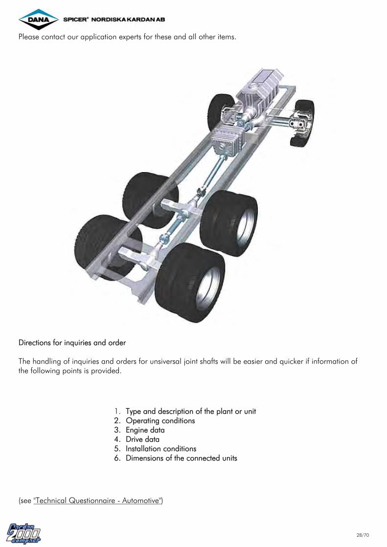
Directions for inquiries and order The handling of inquiries and orders for unsiversal joint shafts will be easier and quicker if information of the following points is provided.
1. Type and description of the plant or unit 2. Operating conditions 3. Engine data 4. Drive data 5. Installation conditions 6. Dimensions of the connected units
(see "Technical Questionnaire - Automotive")

29/70
Installation and Maintenance Installation conditions While rotating, the universal joint has a sinuslike, fluctuating angular speed depending on the deflection angle. As described in detail in the chapter ,,General fundamental theory", this system-linked fault can be offset for a driving line equipped with two or more joints by choosing special joint arrangements. When dimensioning the drive or the auxlliarv drive, the following rules must be observed in practice: Angle conditions of the universal shaft 1. Shaft with two joints
"Z-arrangement"
"W-arrangement"
The deflection angles of the joints must be equal: = This rule is also applicable to front view and top view pictures.
The joint yokes of the connecting shaft must be in one plane. All three shafts must be in one plane.
Note: All these three rules must be observed simultaneously.

30/70
A joint arrangement in two planes must be avoided if possible. lt is always given when the driving and driven shafts are not in the same plane. If this arrangement is unavoidable and rigid on the installation side, this ,,fault" can be kinematically compensated by a joint misalignment.
Front view:
Top view:
For the resulting deflection angles the following equations are applicable:
2. Shaft with three joints In cases where greater distances between units have to be bridged, the universal shaft must be supported by an additional, mostly elastic, bearing.
In order to keep the remaining irregularity in the drive (joint 3) as small as possible, the sum of all irregulanties of the individualjoints must be equal to or almost equal to zero.
(See "Kinematics of Hooke's joints")

31/70
The signs must be entered according to the following sign rule. Here the sign rule is:
for the joint position
for the joint position
The remaining non-uniformity if any should not be greater than:
The minimization of the remaining non-uniformity can also be achieved by the so-called equivalent deflection angle erfolgen.
The sign rule is also applicable here. The equivalent deflection angle = 3° is the equivalent deflection angle of a single joint which corresponds with a degree of non-uniformity U = 0,0027. 3. Shafts with several joints In case of an arrangement with more than three joints proceed as described above. General recommendations for lorry drives:
For fast-running drive shafts observe the instructions on the transverse whirling speeds for installation length. (See "Influence of speed and deflection angle") Choose small resulting deflection angles for the main drive range: (See also (n x ß)perm. "Influence of speed and deflection angle") Minimize the angular difference between the joints and the remaining inequaltity
If these recommendations are not observed, one must reckon with vibrations and noises and with a reduced driving comfort as well as with a reduced lifetime of the units.

32/70
Deflection of joints in two planes If a "classic shaft arrangement" cannot be realized and the joint deflection cannot be changed, this can be offset by turning the joints. For this shaft arrangement the Installation rule that the resulting deflections of the joints must be equal remains in force, i.e.
Plane 1 formed by the driving shaft 1 and the connecting shaft 2 on the one hand and Plane II formed by the connecting shaft 2 and the driven shaft 3 on the other hand form the angle which is offset by turning the joints correspondingly. The torsion angle is determined as follows:
The rotation direction results ifom the side view, i.e. joint 1 must be turned to plane 1 by the angle . The shaft must be mounted according to these statements and this before a possible balancing. This position of the joints must be marked with arrows.

33/70

34/70
lnfluence of speed and deflection angle Speed The permissible speed of the universal joint shaft is influenced by the following parameters:
size of the shaft widening of the yokes due to centrifugal force quality of balancing true running of the connected flanges deflection angle during operation length of the shaft
Speed x deflection angle Theoretical considerations and observations of various applications have shown that certain mass acceleration moments of the centre part of the shaft must not be exceeded if a quiet running of the shaft drives is to be achieved. This mass acceleration moment depends on the speed n, the deflection angle ß and the mass moment of inertia of the centre part of the shaft. The mechanically possible deflection angle for each joint depends on the size of the shaft. Owing to the kinematic conditions of the universal joint described before, the practical deflection angle must be limited in relation to the rotational speed. The following table shows the max. speeds and the max. permissible values for the product
of the various shaft sizes for a moment of inertia of the centre part according to a shaft length of approx. 1500 mm. When approaching the critical rotational speed and in the light of the demand of maintenance of balance quality (see Balancing of Propeller shafts ) , it may be necessary to reduce the rotational speed.
Joint size n max.
[1/min.]
(n x ß) perm.
[°/min.]
2015 2020 2025 2030 2035 2040 2045 2047 2050 2055 2060 2065
6 000 6 000 6 000 6 000 5 600 5 000 4 700 4 500 4 500 4 500 4 100 3 900
27 000 26 000 24 000 22 000 21 000 20 000 19 000 19 000 19 000 18 000 17 000 17 000
Since the quiet running of the universal shaft in practice also largely depends on the installation conditions, the n x ß values shown in the table can only be regarded as a guidance. Slightly higher values are possible. In case of favourable spring and mass conditions the values may be exceeded by up to 50 %.

35/70
Transverse whirling speed Universal shafts are flexible elastic units, which must be calculated considering the bending vibrations and the transverse whirling speed. For reasons of safety the max. perm. operating speed must be sufficiently below the transverse whirling speed. The diagram on the end of this page shows the transverse whirling speeds of the varbus shaft sizes depending on the operating lengths and the tube dimensions shown in the catalogue. The diagram values apply to normal installation conditions with a supposed distance of the centre point of the joint shaft from the adjacent bearing equal to 3 x M and a rigid suspension of the connected units. In order to achieve a safe and quiet running behaviour the max. perm. operating speed, i.e. including a possible excess speed, must not exceed 80 % of the transverse whirling speed shown in the diagram.
If the permissible speed is exceeded, the length of the universal shaft must be reduced or an intermediate bearing must be provided. The following diagrams only refer to universal shafts of the standard design. For special designs with greater length compensations than normal or with other alterations reducing the flexural strength a special calculation of the critical speed is required. In this case please ask our advice. Transverse whirling speed of cardan shafts dependent on operating length

36/70

37/70
Load on connection bearings The bearings of the driving and the driven shafts are strained by statle and dynamic forces and moments. These bearing forces result from: Static bad due to
the weight of the universal shaft the length compensation under torque the torque deviation in case of deflected universal shafts
Dynamic bad due to
the remaining unbalance of the shafts the aperiodical length compensation (axle movement) under torque the torque deviation in case of rotating, deflected shafts and centrifugal forces in case of untrue running of the connected units
Bearing forces due to torque deviation The torque equation for a deflected joint is:
(See "General fundamental theory ") If the transmitted power (N) is taken as constant (no friction losses), the torque relation can also be es follows:
The extremes of the transmission i are:

38/70
Thus also:
Bearing forces due to Iengh alteration
With a constant drive capacity resp. with a constant drive torque and a constant angular drive velocity an irregular torque behaviour is obtained in the drive. Since the torque is only transmitted in the journal cross plane, the cross, however, has a horizontal position with regard to the drive shaft at one moment and a vertical position with regard to the driven shaft at another moment, depending on the position of the yoke, there is, in the former case, a bending torque on the yoke of the driven shaft and, in the latter case, a bending torque on the yoke of the driving shaft. Thus the driven torque fluctuates twice per rotation between the extreme values
/ cos ß and * cos ß
= 0°; 180°
= 90°; 270°

39/70
The universal shaft with two joints in the Z-arrangement shown is Ioaded with the following moments. Here, as for the single joint, only the two extreme positions are shown.
= 90°; 270° =
= 0°; 180° =
In general:
Radial forces on connecting bearings For universal shafts with two joints mounted normally while observing the installation instructions it is usually enough to know the greatest reaction forces in the bearings of the driving and driven shafts, which occur two times per rotation. The following calculation scheme may be helpful. (See "Calculation scheme")

40/70
Axial forces on connecting bearings Axial forces on connecting bearings are encountered in the form of reaction forces due to:
displacement of the engine / transmission and / or transfer box units axle displacements
These axial forces are a function of:
the amounts of torque to be transmitted the sectional dimensions of Ion gitudinal compensating elements the friction coefficient in Ion gitudinal compensating elements the deflection angles of the cardan shaft under operating conditions the relative dynamic displacement of engine and transmission units additional loads due to hydraulic effects arising when the grease
chamber in the Ion gitudinal displacement system is filled beyond capacity

41/70
Calculation scheme of radial forces on connecting bearings
Universal shaft in Z-arrangement Position 0° flange yoke right-angled to drawing plane Position /2 flange yoke in drawing plane
Universal shaft in W-arrangement Position 0° flange yoke right-angled to drawing planePosition /2 flange yoke in drawing plane

42/70
Length dimesions The operating length of a universal shaft is determined by:
the distance between the driving and the driven units the length compensation during operation
The following abbreviations are used: Lz = Compressed length This is the shortest length of the shaft. A further compression is not possible. La = Length compensation The universal shaft can be expanded by this factor La is a constant factor for each universal shaft. An expansion beyond that factor is not permissible. Lz + La = Max. perm. operating length LBmax.
During operation the universal shaft can be expanded up to this length. The optimum working length LB of a universal shaft is achieved if the length compensation is extracted by one-third of its length.
This rough rule appiles to most of the arrangements. For applications where larger length alterations are expected the operating Iength should be chosen in such a way that the movement will be within the limit of the permissible length compensation.

43/70
Arrangements of cardan shafts A tandem arrangement of universal shafts could become necessary
to cope with greater installation lengths to by-pass construction units
Basic forms of shaft combinations: Universal shaft with intermediate shaft
Universal shaft with two intermediate shafts
2 universal shafts with double intermediate bearing
In case of such arrangements the individual yoke positions and deflection angles are to be adjusted with regard to one another in such a way that the degree of non-uniformity (see "Installation conditions") and the reaction forces acting on the connection bearings (see "Load on connection bearings") are minimized.

44/70
Balancing of cardan shafts The cardan shafts used in motor vehides are balanced. This balancing is performed to equalize eccentrically running masses, thereby preventing vibrations and reducing the bad on downstream units as a result of free centrifugal forces. Balancing is carried out in accordance with IS0 Standard 1940. "Balance quality of rotating rigid bodies". According to this standard, the permissible residual imbalance is dependent on the quality grade and operating speed of the balanced component. If the customer does not specify a balancing speed or quality grade, balancing is per formed to GWB Standard 4100-005. This standard reflects the following criteria:
Balancing speed The balanclng speed is selected from a graded scale determined for various cardan shaft sizes. These balancing speed levels are defined on the basis of statistical evaluations of the r.p.m. conditions prevailing in the associated vehicle categories.
Quality grade In defining a quality grade, it is necessary to consider the reproducibility levels achieveable in the customer's own test rig during verification testing. Quality grades are dependent on the following variables: - type of balancing machine (hard, rigid or soft suspension) - accuracy of the measuring system - joint bearing radial play - angular backlash in Iongitudinal displacement direction
FieId analyses have shown that the sum of these factors may result in inaccuracies of up to 80%. This observation has given rise to the definition of the following balancing quality grades: - factor balancing: G16 - customer verification tests: G32

45/70
Flange boltings To connect the cardan shaft to the companion flanges it is imperative to use high-tensile bolts of the quality 10.9 and the corresponding all-metal self-locking nuts of the quality 10 or such bolts and nuts that the manufacturer of the vehicle has prescribed. Complete sets of bolting are available for all DIN and cross-Serrations flanges. The tightening torques Ta given in the table are valid for:
90% utilization of the elastic limit bolts in a lightly-oiled condition (Friction coefficient µ ges. = 0,13). metallic bare surface areas
Do not use molycote paste or any other grease on the bolts and nuts.
For additional information on flange connections, corrosion protection, assembly and dismantling see our specification GWB-A 100-005.
Companion flanges Generally cardan shafts are connected to the units by companion flanges. The companion flange material must have an interfacial pressure of min. 700 N/mm²
Cross-Serration flanges (XS) Joint flange
Hexagon bolt: similar to DIN 931/10.9 Hexagon nut: similar to DIN 980/10 self-locking Type of nut: all-metal
Shaft connection
Thread ∅d [mm]
Length L [mm]
Wrench size [mm]
Flange thickness G1 [mm]
Flange thickness G2 [mm]
Grip G1 + G2 [mm]
Height of nut h [mm]
Torque Ta [Nm]
XS 120 M10 40 17 14 10 24 9 62
XS 150 M12 45 19 16 12 28 11 105
XS 180 M14 50 22 18 14 32 12 170
±20%
We recommend a socket for wrenches Wrench size Order-No. 17 GETA 197-17 GWB ½ 19 GETA 197-19 GWB ½ 22 GETA 197-22 GWB ¾

46/70
Shaft connection
Thread ∅d [mm]
Length L [mm]
Wrench size [mm]
Grip 2 * G [mm]
Height of nut h [mm]
Torque Ta [Nm]
M8 25 13 12/24 8 35
M10 30 17 16 10 70
M12 40 19 20 12 120
M16 45 24 24 16 295
DIN
M16 50 24 30 16 295
± 7%
SAE-flanges Joint flange
Hexagon bolt: similar to DIN 931/10.9 Hexagon nut: similar to DIN 980/10 self-locking Type of nut: all-metal
Shaft connection
Thread ∅d [mm]
Length L [mm]
Wrench size [mm]
Grip 2 * G [mm]
Height of nut h [mm]
Torque Ta [Nm]
M8 30 13 16 8 35
M10 30 17 16 10 70
M10 35 17 19/21 10 70
M12 35 19 16 12 120
SAE
M12 40 19 21 12 120
± 7%
When using bolt connections other than those recommended the torque must be adjusted accordingly in order to guarantee the safety of the connection!
DIN-flanges Joint flange
Hexagon bolt: similar to DIN 931/10.9 Hexagon nut: similar to DIN 980/10 self-locking Type of nut: all-metal

47/70
Safety instructions Our products have been developed and tested in keeping with the latest technological developments. The characteristic features of the products described in our information material or specified in writing by ourselves were subjected to proper and careful inspection. Other layouts are possible but are subject to our written confirmation. The knowledge of the various demands on our product for a particular application lies with the purchaser, and it is incumbent on him to verify the drawings and documents prepared by ourselves on the basis of the data made available by the purchaser and to examine the suitability of the product for the proposed use. The selection of shaft types and the specification of their sizes on our part shall in all cases be considered as a recommendation only. When using and handling cardan shafts, the following safety instructions must be strictly observed to prevent damage to persons and property.
Where danger to people or material can be caused by rotating cardan shafts, a safety device has to be installed by the user and/or operator. Observe the EC Regulations for Machinery! Installation, assembly and maintenance work may only be carried out by qualified personnel. The operating data of the cardan shafts, such as max. torque, speed, deflection angles, lengths etc. must never be exceeded. If cardan shafts are in any way altered without our written consent, they are no longer covered by our warranty.
Cardan shafts of the series COMPACT 2000 are delivered as complete units ready for installation. The shafts are greased for operation. They are balanced and painted in accordance with the technical information sheets.
The balance state of a cardan shaft must on no account be altered. An inadmissable out-of-balance of a shaft may result in uneven running and premature wear of the joints and the bearings of the units to which the cardan shaft is connected. In extreme cases the cardan shaft could break and shaft components could be thrown at speed from the vehicle or machine.
Further safety instructions are incorporated in the following subjects.

48/70
Transport and storage
To prevent personal injury and damage to the cardan shafts always make sure that the shafts are safely transported and stored.
Please observe the following precautions:
Use strong nylon ropes or lifting belts. When using steel cords, protect the edges. Cardan shafts should be transported in a horizontal position (see illustration). For non-horizontal
transportation additional precautions must be taken to prevent the splined parts from separating. Danger of injury!
When lifting or putting down the shaft, the moving parts (flange yoke and journal cross) may tilt
and lead to injuries. Keep hands away from the joint! Danger of crushed hands!
Avoid bumps and knocks during transport and storage. Do not store or handle the shaft with any stress or load on the cover tube (1).
Use appropriate frames or racks for storage (see example).
When cardan shafts are stored on pallets stacked up on top of one another, the supports must be one below the other because otherwise the tubes may bend and the result may be uneven running or imbalance of the shaft. The supports may only be used in the area of cardan tubes and never in the area of the cover tube or the length compensation.

49/70
When cardan shafts are stored in an upright position, make sure they cannot fall over. Keep cardan shafts in a dry place.
Transport and storage of Centered Double Cardan Shafts In order to prevent any exessive deflection of the double joint and thus damage to the location bearing during transport, the cardan shaft is provided with a transport protection device which encloses the double joint.
The transport protection device must not be removed until the cardan shaft is installed.
Use appropriate frames or racks for storage. Use chocks or blocks to prevent cardan shaft from rolling. Secure shaft against falling over if it is stored in a vertical position.

50/70
Installation/dismantling
In order to guarantee the properties of the cardan shaft as described in the information brochure they must not be altered. Whenever people or material might be endangered by rotating cardan shafts, the user must take for the corresponding safety measures.
Safety relevant components of the vehicle and brake lines, electric lines, hydraulic and fuel lines must be arranged in such a way that they cannot be damaged by a defective cardan shaft. Danger of breakdown of important units! Danger of fire!
Suitable safety devices (e.g. catch bows, solid safety guards) must be provided to prevent the parts of the shaft from being thrown around and to prevent damage to other parts of the unit if the cardan shaft should become defective. In the view of GWB such safety devices may be dispensed with provided that a comparable form of security is guaranteed during operation of the vehicle through suitable engineering measures taken by the vehicle manufacturer. Danger to life!
The fronts of the DIN and SAE shaft flanges and companion flanges must be free of dust, grease or paint in order to guarantee a safe connection. The anti-corrosive on cross-Serration flange teeth need not be removed. Other particles must be removed.
Be careful when handling the cardan shaft. Freely moving yokes may cause injuries!
Check position of the yokes (1) of the shaft. Observe the arrow markings (2). (They must be in alignment.) The spline components are matched for a smooth fitting and must not be interchanged or remounted at a different angle.
Before installation remove any transport retainer device. If in doubt please contact the supplier. Check the side and radial runout as well as the fit of the mounted flanges and the connected
units (see companion flanges for cardan shafts). Do not turn the joints of the cardan shafts with assembly levers because this may damage the
grease nipples or seal arrangement on the bearings. When painting ensure that the sliding range of the seal (length compensation La) is protected.

51/70
Protect rilsan coated splines (sleeve muff or sleeve yoke) against
- heat - solvents - mechanical damage
When cleaning cardan shafts, do not use aggressive chemical agents or pressurized water or steam jets because the seals may be damaged and dirt or water may penetrate.
If cardan shafts are subjected to higher temperatures, e.g. due to noise-reduction measures or retarders, suitable means should be provided to ensure that the limit values are not exceeded.
Installation of drive lines Midship shafts are supplied complete with centre bearings ready for installation. The centre bearing and the companion flange are fixed on the midship shaft by means of bolts which are secured against working loose. For reasons of safety these bolts must never be loosened or retightened on new shafts. They may only be loosened for repair work, but they must be properly secured again after the repair.
Midship shaft without length compensation with centre bearing
To avoid cases of non-uniformity, drive lines consisting of the midship shaft with the centre bearing and the normal cardan shaft must be installed in accordance with the yoke position of the joints prescribed by vehicle manufacturer.
When installed, the centre bearing must be vertical in all directions with regard to the horizontal axis of the midship shaft and be in a central position. Suitable mounting supports must be provided on the frame side. A continuous stable support must be provided between the centre bearing bracket and the mounting support (see illustration).
52/70
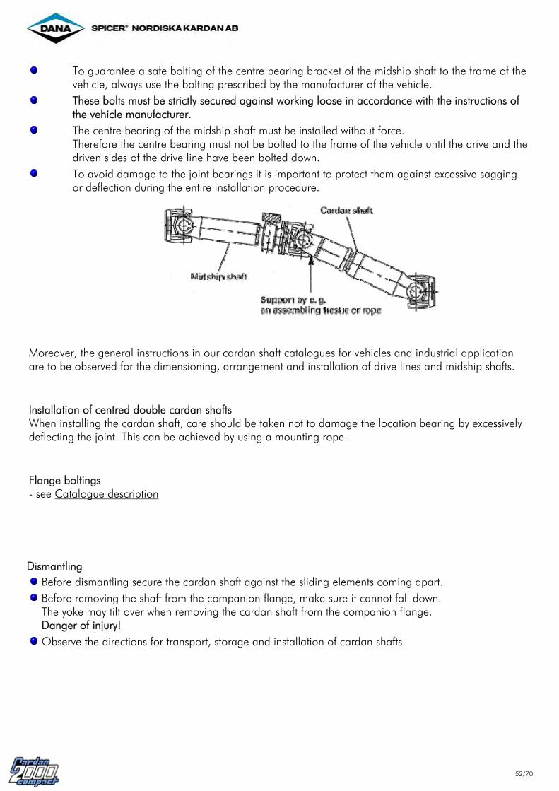
To guarantee a safe bolting of the centre bearing bracket of the midship shaft to the frame of the
vehicle, always use the bolting prescribed by the manufacturer of the vehicle. These bolts must be strictly secured against working loose in accordance with the instructions of
the vehicle manufacturer. The centre bearing of the midship shaft must be installed without force.
Therefore the centre bearing must not be bolted to the frame of the vehicle until the drive and the driven sides of the drive line have been bolted down.
To avoid damage to the joint bearings it is important to protect them against excessive sagging or deflection during the entire installation procedure.
Moreover, the general instructions in our cardan shaft catalogues for vehicles and industrial application are to be observed for the dimensioning, arrangement and installation of drive lines and midship shafts. Installation of centred double cardan shafts When installing the cardan shaft, care should be taken not to damage the location bearing by excessively deflecting the joint. This can be achieved by using a mounting rope. Flange boltings - see Catalogue description Dismantling
Before dismantling secure the cardan shaft against the sliding elements coming apart. Before removing the shaft from the companion flange, make sure it cannot fall down. The yoke may tilt over when removing the cardan shaft from the companion flange. Danger of injury! Observe the directions for transport, storage and installation of cardan shafts.

53/70
Companion flanges Generally cardan shafts are connected to the units by companion flanges. The companion flange material must have an interfacial pressure of min. 700 N/mm². For standards of frictional grip flanges see ISO 7646 (DIN flanges), ISO 7647 (SAE flanges) and positive connection flanges with 70° cross-Serration ISO 8667 (XS flanges). The accurate running of a cardan shaft requires certain tolerances for the axial and radial run-out (see by DIN-flanges ISO 7646, by SAE-flanges ISO 7647 and by XS-flanges ISO 8667). x = axial run-out y = radial run-out
The dimensions of the companion flanges correspond with those of the same size of cardan shafts, except for the centering depth FA and the fit CA, and can be taken from the tables in the catalogues or from the following tables. For better bolt locking we recommend designing the recessed diameter of the companion flange as a bolt head Iocation and inserting the bolts from the companion flange side. In this case an adequate distance Zmin must be maintained between the flange and the adjacent unit. Zmin = bolt length (incl. bolt head). If it is not possible to insert the bolts from the companion flange side, the bolts can he inserted from the joint side, except for some sizes. Make sure that the nuts can be easily tightened on the companion flange side. If necessary, use companion flanges with pre-assembled bolts.

54/70
Design A - Connection with staggered teeth according to ISO 8667
Shaft connection
A [mm]
B [mm]
I(1) x H(2) Design
XS 120 122(3) 100 4 x 11 A XS 150 155(4) 130 4 x 13 A XS 180 180 150 4 x 15 A XS 200 200 165 4 x 15 A (1) Number of bolt holes per flange (2) Tolerance + 0,2 mm (3) Ø 120 mm also possible (4) Ø 152 mm also possible Design B - DIN connection according to ISO 7646
Shaft connection
A [mm]
B [mm]
CA [mm]
FA [mm]
I(1) x H(2) Design
90 74,5 47 h7 2,3 - 0,2 4 x 8,1 B 100 84,0 57 h7 2,3 - 0,2 6 x 8,1 B 120 101,5 75 h7 2,3 - 0,2 8 x 10,1 B 150 130,0 90 h7 2,3 - 0,2 8 x 12,1 B 165 140,0 95 h7 2,3 - 0,2 8 x 16,1 B 180 155,5 110 h7 2,3 - 0,2 10 x 16,1 B
DIN
225 196,0 140 h7 4,0 - 0,2 12 x 16,1 B (1) Number of bolt holes per flange (2) Tolerance + 0,2 mm

55/70
Design C/D - SAE connection according to ISO 7647
Shaft connection
A [mm]
B [mm]
CA [mm]
FA [mm]
I(1) x H(2) Design
1100 87 69,85 57,10 H7 2,0 + 0,2 4 x 8,1 C 1300 97 79,37 60,32 H7 2,3 + 0,2 4 x 10,1 C 1400 116 95,25 69,85 H7 2,3 + 0,2 4 x 12,1 C 1500 151 120,65 95,25 H7 2,3 + 0,2 4 x 14,1 C 1510 146 120,65 95,25 H7 2,3 + 0,2 4 x 12,1 C 1600 175 155,57 168,22 H7 1,5 + 0,2 8 x 10,1 D 1700 203 184,15 196,86 H7 1,5 + 0,2 8 x 10,1 D
SAE (Spicer)
1800 203 184,15 196,86 H7 1,5 + 0,2 12 x 10,1 D
(1) Number of bolt holes per flange (2) Tolerance + 0,2 mm

56/70
Maintenance
Maintenance work on cardan shafts used in vehicles and industrial equipment must be done at regular intervals. The scope and the intervals of maintenance work depend on the individual operating conditions of the vehicle or the equipment. Maintenance intervals for cardan shafts in commercial vehicles Depending on the type of vehicle, the mileage or the service life and the operating conditions two different scopes and intervals of maintenance are required. These are the "minor inspection" and the "major inspection".
Inspection intervals Use of vehicle
Minor inspection Major inspection
Commercial vehicles in long-distance traffic or similarly used vehicles
Every 100.000 km or after 1 year max.
Every 500.000 km or after 5 years max.
Commercial vehicles used on road and off road and in city traffic and similar
Every 50.000 kmor after 1 year max.
Every 300.000 km or after 5 years max.
Buses in long-distance traffic
Every 100.000 km or after 1 year max.
Every 300.000 km or after 3 years max.
Buses in city traffic
Every 50.000 kmor after 6 months max.
Every 200.000 km or after 2 years max.
Every 25.000 kmor after 6 months max.
Every 100.000 km or after 2 years max.
Commercial vehicles used on sites, communal vehicles, construction machines, cranes, vehicles used in agriculture and forestry, tractors, military vehicles and similar After a change of the vehicle owner or in case of an accident we recommend a "major inspection" of the cardan shaft.

57/70
Scope of maintenance Minor inspection The "minor inspection" includes checking the cardan shaft installed in a vehicle or in an industrial plant.
Check the bolts of the flanges and of the centre bearing bracket for tightness (e.g. undamaged paint coat). If necessary, retighten the bolts with a suitable torque wrench and the torques prescribed by the manufacturer of the vehicle or equipment. Check whether there are snap rings on all bearing bushes. Check whether balance weights are loose or missing. Check the bottoms of the bearing bushes for change of colour or form due to excessive heat. Visual inspection of the seals of bearing bushes and the length compensation. Defective seals may result in excessive grease loss and breakdown of the cardan shaft. Check whether there are grease nipples on the journal crosses and whether they are in good condition (exception: maintenance-free joints). Check whether the rilsan coat on the sleeve is damaged or shows abrasion. Visual inspection of the centre bearings of drive lines with regard to: - correct position of the rubber cushion in the centre bearing bracket - correct position of the flange shaft
If the distance between the rubber cushion and the outer flinger is too large, the centre bolt may work loose. In this case a check should be made as a part of a major inspection. Carry out a visual inspection for possible damage, e.g.: - damaged paint coat - deformed tubes - eccentricity of the length compensation cover tube - cracks on components and tube Check the joints and the length compensation for visible or tangible backlash.
If the inspection shows that the cardan shaft is damaged, it must be removed at once and sent to a repair shop that is authorized either by us or by the manufacturer of the vehicle or the equipment. Furthermore, the vehicle or the equipment must be immediately taken out of operation in the case of any extraordinary noise, vibration or otherwise abnormal behaviour. Before recommissioning the cardan shaft it must be checked within the scope of a "minor inspection".

58/70
Major inspection Each "major inspection" includes the scope of checking prescribed for a minor inspection. In addition, the cardan shaft must be removed from the vehicle or the equipment for the "major inspection". The following checking or work must be carried out on the cardan shaft:
Checking the joint bearings - Check the two flange yokes for tangible backlash or resistance (e.g. hooking) by deflecting them by
hand into vertical and horizontal positions (swing them to and fro). - Grease the cross assemblies through the grease nipples and check whether the grease escapes from
the seals. If no grease escapes from one or more bearing bushes of a cross assembly or if grease escapes together with water, rust or dirt, the cardan shaft must be sent to an authorized shop for repair.
If the joints are in proper condition, regrease them through the grease nipples until the grease escapes from the seals. Checking the length compensation components The involute spline is centred and guided on the spline outer dia. This design allows a maximum backlash of 0,2 mm. The radial backlash need not be checked. - Extend the cardan shaft by approx. 45 mm and place the lugs of the inner yokes at points A and B
on a solid support (see illustration).
Fix the dial gauge holder at point C next to the weld on the tube and place the dial gauge directly next to the weld of the protective sleeve (cover tube). Lift the cardan shaft at its center of gravity so that the supports at points A and B become free. Read axial backlash on the dial gauge. The max. permissible value is 0,17 mm.
- Visual checking of the parts: Extend the cardan shaft completely and check the length compensation for damage to the inside and outside areas of the spline muff and the teeth of the yoke shaft.
- Check the seal of the cover tube for damage. If the length compensation is undamaged: - regrease the parts of the length compensation in the sealing area (for grease see Lubrication) and
bring the length compensation together to its original length. Attention: Make sure that the marking arrows are opposite one another!

59/70
Check the centre bearing of drive lines with regard to: - damage to the rubber cushion - firm seat of the ball bearing in the rubber cushion
Retighten the central bolt with a torque of 350 Nm. Attention: Centre bearings of older designs with a central nut or holding plate and two bolts (not shown) must not be retightened because the bonding may become damaged and the securing function of the bolting is no longer guaranted. After checking (by retightening) or loosening the bolting a completely new bonding is required.
If a major or minor inspection reveals any damage to the shaft, It must be sent to a repair shop that is authorized by either GWB or the manufacturer of the vehicle or equipment. Attention: After each repair the cardan shaft must be rebalanced dynamically. When reinstalling the cardan shaft, please observe the relevant installation instructions (see Installation/disassembly). If the cardan shaft is obviously twisted due to over-loading (plastic deformation), it can no longer be used or repaired.

60/70
Lubrication
Cardan shafts of the series COMPACT 2000 are lubricated ready for operation. The length compensation of the Standard designs is maintenance-free. This does not apply to special designs with an extra large length compensation and a large deflection angle (e.g. cardan shafts between tandem axles). Such a length compensation requires regreasing through a grease nipple in the sealing sleeve of the spline protection until the grease escapes at the scraper seal of the sealing sleeve. The centre bearing is protected by a cover and, filled with grease, is service-free.
Cross assemblies must be regreased. The grease reservoir in the cross assemblies can be replenished through a grease nipple. Regreasing must be carried out until the grease escapes out from the seals of the bearings.
If it is not possible to grease all four bearings of a cross assembly (i.e. no grease escapes out from the seals), the bearings must be assumed to be damaged. In this case the cardan shaft must be removed and the cross assembly must be replaced in an authorized repair shop. We recommend replacing the other cross assemblies at the same time.
For the lubrication of cardan shafts only that grease may be used, which is defined in our standards 4006-005 corresponding to the different application temperatures. Do not use lubricants with MoS2 additives. Clean grease nipples before lubricating. Do not lubricate at high pressure or with pressure surges. Cardan shafts that have been stored for more than 6 months must be regreased before use. The cardan shaft must not be cleaned with pressurized water or a steam jet. In case of doubt the shaft must be regreased until the grease escapes from the seals of the bearings.

61/70
Recommended regreasing intervals for cardan shafts in commercial vehicles Unless otherwise prescribed by the manufacturer of the vehicle, we recommend the following regreasing intervals. The data in the table refer to European and similar conditions. Operating conditions other than those shown here may require shorter regreasing intervals. - Regreasing intervals for joints (applicable only in conjunction with approved greases)
Use of vehicle Regreasing intervals
Commercial vehicles in long-distance traffic or similarly used vehicles
Every or after
50.000 km 1 year max.
Commercial vehicles used on road and off road and in city traffic and similar
Every or after
25.000 km 1/2 year max.
Buses in long-distance traffic
Every or after
50.000 km 1/2 year max.
Buses in city traffic
Every or after
25.000 km 1/4 year max.
Every or after
12.500 km 1/4 year max.(250 h)
Commercial vehicles used on sites, communal vehicles, construction machines, cranes, vehicles used in agriculture and forestry, military vehicles* and similar
* if driven through water **shorter greasing intervals **are recommended
- Greasing intervals for length compensation and centre bearing As standard the length compensation and the centre bearing are service-free. The lubricating intervals for types designed for periodic relubrication are the same as for joints.

62/70
Repair For reasons of safety, cardan shafts may only be repaired by competent repair shops of vehicle or plant manufacturers, by GWB or by repair shops authorized by GWB . The repair of cardan shafts is carried out in a professional manner by our Cardan Shaft Service experts. Overhauling and repair work is carried out by using original spare parts only. Manufacturer specifications for the inspection of propeller shafts and for the exchange of individual components and groups of components The following GWB standards and specifications/directions may be be requested/demanded from GWB as required: - Dismantling/assembly of complete Unit Pack Assemblies - Dismantling/assembly of Centre Bearing Assemblies - Guidelines for the inspection of Compact 2000 cardan shafts - Guidelines/service information for centred Double-Cardan Shafts

63/70
Modification of Propeller Shafts Advice on technical changes to propeller shafts in drive trains as a result of vehicle conversions Changes to vehicles which my have an effect on the drive train include, among others: - Changes to the wheelbase - Later fitting of retarders - Replacement of gearbox or differential - Later fitting of ancilliary drives The following advice must be followed on all accounts:
Observe safety advice on taking out and replacing the cardan shaft (see Installation/Dismantling of cardan shafts).
All technical changes to our propeller shafts (e.g. extending length, shortening, flange changes etc.) are to be carried out exclusively by our Service Organisation ). (Subsequent straightening and balancing will be necessary)
Length changes to propeller shafts require changes in the working angle in the as-fitted state. For general guidelines and limit values (see Installation conditions ).
When extending the length of a propeller shaft attention must be paid to guard against critical bending speeds being reached. In some cases an additional propeller shaft with a centre bearing may be required.
Engine, gearbox, distribution box, differential and primary retarder must be tested on and brought to the same fitted plane of inclination in order to avoid unequal working angles within the individual propeller shafts.
On re-installation of propeller shafts the length compensation (splined shaft connection) must on all accounts be lined up correctly (with arrows pointing ). (see Installation/Dismantling of cardan shafts)
On re-tightening the bolt on the flange connection attention must be paid to the maintenance of the correct bolt starting torque. A torque wrench will be necessary. (see Flange boltings )
Should any questions or technical problems arise complete the "Technical Questionnaire" and send it, along with the installation plan and any supplementary details on the existing cardan shafts, and on any which are to be re-conditioned, to the given GWB e-mail address.
64/70
After sales service
I. Home
GKN Service International GmbH Service-Center Berlin Marzahner Chaussee 211 D-12681 Berlin Telefon: (030) 54 99 82-51 Telefax: (030) 54 99 82-60
GKN Service International GmbH Service-Center Hamburg Ottensener Straße 150 D-22525 Hamburg Telefon: (040) 54 00 90-0 Telefax: (040) 54 00 90-44
GKN Service International GmbH Service-Center Hannover Alter Flughafen 14a D-30179 Hannover Telefon: (0511) 67 10 11 Telefax: (0511) 63 85 33
GKN Service International GmbH Service-Center Dortmund Frydagstraße 21 D-44536 Lünen-Lippholthausen Telefon: (0231) 441025 Telefax: (0231) 458513
GKN Service International GmbH Service-Center Düsseldorf Gutenbergweg 2/Max-Planck-Str. D-40699 Erkrath Telefon: (02104) 93 37-46 Telefax: (02104) 93 37-43
GKN Service International GmbH Service-Center Frankfurt Am Erlenbruch 5 D-63505 Langenselbold Telefon: (06184) 93 94-11 Telefax: (06184) 93 94-19
GKN Service International GmbH Service-Center Nürnberg Am Keuper 1 D-90475 Nürnberg Telefon: (09128) 92 75-3 Telefax: (09128) 92 75-40
GKN Service International GmbH Service-Center Stuttgart Max-Eyth-Straße 12 D-71254 Ditzingen Telefon: (07156) 93 94-0 Telefax: (07156) 93 94-25
GKN Service International GmbHService-Center München Siemensstr. 11 D-85221 Dachau Telefon: (08131) 90804-0 Telefax: (08131) 90804-25
GKN Service International GmbHService-Center Halle Mägdeberge 9 D-06188 Braschwitz Telefon: (034604) 2 06 51 Telefax: (034604) 2 06 54
GKN Service International GmbHService-Center Dresden Köhlerstraße 16 D-01239 Dresden Telefon: (0351) 2 88 10 36 Telefax: (0351) 2 88 10 39

65/70
II. Abroad
Australia / Australien Hardy Spicer Australia trading as Unidrive Pty. Ltd. P.O. Box 146 Rosebank M.D.C. Clayton, Victoria 3168 Tel. 0061-39 54 24 100 Fax 0061-39 54 48 117 Email: [email protected]
Austria / Österreich GKN Service Austria GmbH Slamastrasse 32 A-1232 Wien Tel. 0043-1-61 63 880 Fax 0043-1-61 63 880 28 Email: [email protected]
Belgium / Belgien S.A.B. Glaenzer Seurre B.N.V. au. Me. Paul Gilsonlaan 441 B-1620 Drogenbos Tel. 0032-2-37 11 811 Fax 0032-2-37 11 826 Email: [email protected]
Brazil / Brasilien Dana Albarus S.A. av. Presidente Medice, 939 Osaco - Sao Paulo - Cep: 06280-000 Tel. 0055-117 06 34 89 Fax 0055-117 06 17 50 Email: [email protected]
Denmark / Dänemark Dansk Uni-Cardan A/S Baltorpbakken 10 DK-2750 Ballerup Tel. 0045-4486 6844 Fax 0045-4486 8822 Email: [email protected]
Egypt / Ägypten Landmark Mechanical Works Behind 27a Ismailia Street Roush dy, Alexandria Tel. 00203-544-9201/9202 Fax 00202-544 4703 Email: [email protected]
Finnland / Finnland Oy Unilink AB Lapinrinne 1 FIN-00180 Helsinki-Helsingfors Tel. 00358-9-68 66 170 Fax 00358-9-69 40 449 Email: [email protected]
Hungary / Ungarn Szücs Co. Kardantech KFT Ipari kepriselelek Aradi Vértanúk út 16 H-9022 Györ TeI. 0036-96-518 930 Fax 0036-96-518 931 Email: [email protected]
Hidropress Soroksari UT150 H-1095 Budapest TeI. 0036-1-280 63 48 Fax 0036-1-280 71 71
Indien / Indien Hindustan Hardy Spicer Ltd. 78-B, Dr. Annie Besant Road Worli, Bombay 400018 Tel. 0091-22-377 451-3 Fax 0091-22-493 193-5 Email: [email protected]
I. R. Iran / I. R. Iran Ali Reza Harati No. 37 Ghobadian St., Vali-Asr Ave. Teheran Tel. 021-87 70-217/206 Fax 021-87 83 988 Mobile: 0911-2041093
Ireland / Irland GKN International (Ireland) Ltd. Dublin Industrial Estate Glasnevin Dublin 11 Tel. 00353-1-77 122-5/6/7
Israel / Israel Frank Agencies P.O. Box 22307, 10 Pinkas Str. IL-62661 Tel Aviv Tel. 00972-3-54 41 941-46 Fax 00972-3-54 41 438 Email: [email protected]
Italy / Italien Spicer Italcardano S.p.A. Via Torino 10 I-13044 Crescentino (Vercelli) Tel. 0039-01-61 83 33 11 Fax 0039-01-61 84 37 71 Email: [email protected]
Poland / Polen Cardan Polska Sp. zo.o. ul. Dabrowskiego 262 PL-60406 Poznan Tel. 0048-61-8477001 Fax 0048-61-8477011 Service 24h 0606449944 Email: [email protected]
Saudi-Arabia / Saudi Arabien C.H. Tecke GmbH Hamburger Str. 103 D-24558 Henstedt-Ulzburg Tel. 041-93 95 81 3 Fax 041-93 95 81 40 Email: [email protected]
Sweden / Schweden Svenska Uni-Cardan AB Stensätravägen 9 Box 3100 S-12703 Skeärholmen Tel. 0046-86039700 Fax 0046-86039702 Email: [email protected]
Switzerland / Schweiz Schaffner - Behrend AG Althardstrasse 141 CH-8105 Regensdorf Tel. 0041-1-871 60 70 Fax 0041-1-871 60 80 Email: [email protected]
Spain / Spanien Gelenk Industrial S.A. Balmes, 152 E-08008 Barcelona Tel. 00349-3-2374245 Fax 00349-3-2372580 Email: [email protected]
South Africa / Süd-Afrika MIDAS Ltd. (TMI Propshafts) 294 Brickfield Road Meadowdale, GERMISTON 1401 Tel. 0027-11 879 6 322 Fax 0027-11454 0 380 Email: [email protected]

66/70
France / Frankreich Glenco Industrie 1565, Route de Quarante-Sous F-78630 Orgeval Tel. 0033-1-39 11 80 00 Fax 0033-1-39 75 47 12 Email: [email protected]
Greece / Griechenland Hellas Cardan GmbH P.O. Box 40105 GR-56430 Stawrupolis Tel. 0030-1-65 68 06 Fax 0030-1-65 68 06
Great Britain / Großbritanien GKN Driveline Ltd. Unit 5, Block 79, Kelvin Avenue Hillington Industrial Estate Glasgow G52 4LT Tel. 0044-141-88 32 206 Fax 0044-141-88 31 589
GKN Driveline Ltd. Burton Street, Leek Staffs. ST13 8BX Tel. 0044-1538-38 42 78 Fax 0044-1538-37 12 65
GKN Driveline Ltd. Unit 5, Kingsbury Buisiness Park Kingsbury Road, Minworth Sutton Coldfield, B76 9DL West Midlands Tel. 0044-121-31 31 606 Fax 0044-121-31 32 074
Japan /Japan Najico Spicer Co., Ltd. Tsukiji Najico Bld. 2nd Floor 10-10,3-chome, Tsukiji, Chuo-Ku Tokyo 104-0045 Tel. 0081-3-3549-7767 Fax 0081-3-3549-7769
Korea / Korea Dana Korea Co., Ltd. 8th Floor, Asia Tower, No. 726, Yokosam-Dong, Kang Nam-Ku, Seoul, 135-719 Tel. 0082-2 563 9451-3 Fax 0082-2 563 1762
Netherlands / Niederlande GKN Service Benelux B.V. Haarlemmer-Straatweg 155-157 NL-1165 MK Halfweg Tel. 0031-20-40 70 20 7 Fax 0031-20-40 70 22 7 Email: [email protected]
Norway / Norwegen Uni-Cardan NORGE A.S. Postboks 40 N-0409 Oslo 4 Tel. 0047-22098800 Fax 0047-22098809 Email: [email protected]
Portugal / Portugal Sipavel LDA Rua do Acucar, 88-ARM-8 P-1900 Lisboa Tel. 00351-1-8681587/88/89 Fax 00351-1-8681527
Czech Republic / Slovakia Rudolf Bucek Mladcova 383 CZ-76001 Zlin Tel. 00420-57-7142004 Fax 00420-57-7243478 Email: [email protected]
Turkey / Türkei Orbis Ticaret Mümessilik ve Danismanlikhanesi TR-80072 Beyoglu P.O. Box 151 Istiklal Cad. Beyroglu Is Merkezi 361 Blok B Kat 1 No 120-121 Beyoglu-ISTANBUL Tel. 0090-212-251 1002 Fax 0090-212-2518721
USA / USA GWB North America Merovan Business Center 1200 Woodruff Road Suite A-5 Greenville, S.C. 29607 Tel. 001-864-987-0281 Fax 001-864-987-0295

67/70
Pag. 1
SPICER DRIVESHAFT EUROPE
Technical Questionnaire
- Automotive -
Adressed to SPICER Comp.
DANA
NKA
IC
U.K
Frankreich
Italien
Customer
Adress
Telephone, Fax Production start:
Vehicle model
No. of wheels x No. of driven wheels
4 x 2 4 x 4 6 x 2 6 x 4 6 x 6 8 x 2 8 x 4 8 x 6 8
x 8
Wheelbase: Other:
Type of vehicle
Truck
Bus
Excursion Coach
Articulated Vehicle
Other
Coach
Kind of operation (% of time)
Long Dist.: [%]
Regional: [%]
Urban: [%]
Off Road: [%]
Other: [%]
Service Temperatures
Max. Service Temp. [°C]
Peak Temp. [°C]
Min. Service Temp. [°C]
Max. vehicle speed
. Vmax [km/h] combinated with Iax
Normal
Altern. 1
Altern. 2
Engine
Gear Box
Transfer Box
Tyre
Model: Max.
Power: PENG [kW]
Speed: nENG [rpm] Overspeed:
nENG [rpm]
Torque: TENG [Nm]
Diesel: Petrol:
No. of cylinders:
Model: Type: Automatic Manual
1. Rear Ratio:
i-Low: i-High: i-Rev:
Model:
i-High: i-Low Distribustion:
Front: [%]
Rear: [%]Diff. Lock:
Yes No Permanent:
Yes No
Model:
Stat. Radius [m]
Dyn. Radius
[m]
Friction u [m]

68/70
Pag. 2
SPICER DRIVESHAFT EUROPE
Technical Questionnaire
- Automotive -
Adressed to SPICER Comp.
DANA
NKA
IC
U.K
Frankreich
Italien
Clutch
Friction Clutch
Fluid Clutch
Torque Converter Stall Torque Ratio
iC= Max. Stall Torque
TTC= [Nm]
Retarder (Model)
Electric
Primary
Hydraulic
Sekundary
Break Torque [Nm]
Weights Gross comb. weight GCW [t] Gross vehicle weight GVW [t] Max. weight 1st front axle FA1 [t] Max. weight 2st front axle FA2 [t] Max. weight 1st rear axle RA1 [t] Max. weight 2st rear axle RA2 [t] Max. weight other axles W [t]
Axle Type Ratio Normal Alternativ
Total Axle Ratio: iax
Differencial Ratio: idiff
Wheel Hub Ratio: ihub
Differential lock Single wheel suspension
Yes
Length
Yes
No
Cross
No
Comments
In addition we ask for the following information:
- Arrangement of propshafts in vehicle (Sketch) - Normal operating length Lmin. and Lmax. - Normal operation deflection angles ßmin. and ßmax.
- Extreme conditions of length and deflection angles Lmax. and ßmax.
- Flange connections (Sketch or exact description) - Limited swing diameter Yes/No - Type of mission/load spectrum

69/70
Alphabetic Index
42 Arrangements 64 After sales service
37 Bearing forces 44 Balancing 44 Balancing speed 6 Bearing life
6 Capacity 14 Cardan shaft with length compensation 13 Cardan shaft without length compensation10 Cardan shaft variants of combinations 7 Centre bearing assembly 22 Centre bearings 17 Centred double joint on both sides 18 Centred double joint on one side
29 Deflection of joints in two planes 50 Dismantling 6 Dynamic behaviour
27 Fatigue Strength 20 Flange fittings (DIN) 21 Flange fittings (SAE) 9 Flange variants 37 Forces on connecting bearings 8 Friction type (DIN/SAE)
50 Installation 29 Installation conditions 34 Influence of speed and deflection angle
23 Kinematics of Hooke's joint
42 Length dimensions 27 Lifetime 37 Load on connection bearings 6 Logistics 60 Lubrication
56 Maintenance 14 MIS-shaft
6 Operating Temperature
6 Protection of environment 8 Positive engagement (x-serration)
44 Quality grade
63 Modification of Cardan Shafts 56 Regreasing intervals 62 Repair
47 Safety instructions 57 Scope of maintenance 15 Short coupled cardan shaft 6 Short design 7 Sliding joint 34 Speed 34 Speed x deflection angle 48 Storage 27 Structural Strength 11 Survey of sizes
67 Technical Questionnaire 48 Transport 34 Transverse whirling speed
7 Unit pack - regreaseable 7 Unit pack - maintenace-free
8 Variants of connections
41 W-arrangement 6 Weight
19 X-Serration flange fittings (XS)
41 Z-arrangement