General cataloGue Photovoltaic - Riello UPS...
76
GENERAL CATALOGUE PHOTOVOLTAIC > 2015-2016
Transcript of General cataloGue Photovoltaic - Riello UPS...

General cataloGuePhotovoltaic> 2015-2016
RPS S.p.A. - Member of the Riello Elettronica Groupviale europa, 7 - 37045 leGnaGo (verona) - italyt +39 0442 635811 - F +39 0442 629098www.riello-ups.com - [email protected]
CAT
GEN
X0Y
15C
AGB


Thanks to the credibility gained over decades of activity and presence in diverse markets, Riello Elettronica is a secure point of reference in the industrial world. With Riello UPS brand, the company is currently the world leader in the UPS (market) segment.
AREAS OF BUSINESSA world without energy cannot be imagined. Everything moves and depends on energy. In our advanced society, any interruption to the power supply, like an electricity transmission grid black-out, brings home the fundamental importance of energy in our every-day lives. If we wish to maintain the delicate balance between man and nature, energy must be managed, generated and supplied securely, with minimum environmental impact. Environmental considerations are now at the heart of every project and investment decision and reflect the real need of changing our thoughts on the production and consumption of energy.
ENERGY | Our core business is energy conversion and the production of Uninterruptible Power Supplies (UPS) devices that guarantee the quality of electricity and continuity of business, power supply and the correct functioning of systems even under critical conditions. The Riello Elettronica Group passionately pursues the objective of reducing energy consumption to contribute to the sustainable development of our planet. We intend to achieve this objective with a combination of eco-sustainable projects, research and investment in new technologies for clean and renewable (energy) sources and by creating solar energy conversion systems (inverters) and cogeneration systems.
AUTOMATION | The Group has a strong presence in the sector for control and domestic and industrial automation systems. We work with a passion for progress, completely adhering to laws, regulations and the environment. We design, develop, produce and distribute complete access control automation systems.
SECURITY | We design and produce a complete range of anti-intrusion, fire detection and home automation solutions. Our products are designed to guarantee top-notch performances and maximum levels of employee security. We use advanced technologies to create products that conform to international quality standards.
BUILDING MANAGEMENT | The Group is also involved in the building management and environmental protection by investing in agricultural holdings to develop and reclaim the land.
Riello Elettronica and Riello UPS.Let us continuously transform energy.
Continuous growth and outstanding performance: This is Riello Elettronica, the expression of an entrepreneurial tradition oriented towards innovation, global challenges and the development of the “Made in Italy” technology in the international markets.
2

COMPANY DIVISIONS ENERGY
Riello UPS Leader in uninterruptible power supply thanks to a complete range of professional UPS (Uninterruptible Power Supply).
Aros Solar Technology Photovoltaic inverters (FV) and energy storage systems for any requirement, from small domestic systems to solar energy stations.
EnerBlu Cogeneration Cogeneration systems for energy saving requirements.
AUTOMATIONCardin A wide range of automation systems for access control.
Ceimu Hydraulic PV plants and lubrication and automation systems for a wide variety of industrial applications.
SECURITY AVS Electronics Anti-intrusion systems, fire alarms and home automation.
Gamma Systems Products for worker security in hazardous areas.
OFFICETechnology and innovation have always been distinctive traits of Riello Elettronica. These are the factors behind our global and local success and the expression of an entrepreneurial tradition that can be found in and around Verona. We are
proud to maintain close ties with our local communities with our sponsoring and donation programmes that support local cultural activities, sports and charities and express the growing social responsibility of the Group.
23SUBSIDIARIES
800EMPLOYEES
80COUNTRIES PRESENT
9PRODUCTION SITES
2014 Data
RIELLO POWER SYSTEMS
RIELLO UPSGmbH
RIELLO TDL
RIELLOENERDATA
CONSTANTPOWER SERVICES
RPS S.p.A.
RIELLO UPS AUSTRALIA
ALARM INTERNATIONALSYSTEM
AVS ELECTRONICS
RIELLOUPS
CARDIN ELETTRONICA
FRANCE
CEIMU
RIELLO PCIINDIA
RIELLO UPSASIA
RIELLO UPS SINGAPORE
GAMMASYSTEM
RIELLO ELETTRONICA
ENERGY
AUTOMATION
SECURITY
CARDIN ELETTRONICA
BELGIUM
ENERBLU COGENERATION
S.p.A.
RIELLO UPS Ltd
BANATTIkA(Riello UPS Romania)
CARDIN ELETTRONICA
GERMANY CARDINELETTRONICA
3www.riello-ups.com

In a company like AROS Solar Technology, support and services to users and the company employees are part of a project for the ongoing search for quality and excellence, representing the starting point for building a partnership with customers which becomes stronger every day.
That’s why the Control Centre, the feather in the cap of a system built around the real needs of those who use AROS Solar Technology products and solutions, is able to read the status of the appliances in real-time across the network, and obtain immediate intervention in the event of an emergency. That’s why ongoing training for technical and commercial operators at the main AROS Solar Technology site or at the sites of its customers ensures high problem solving expertise and very low response times. That’s why the success of AROS Solar Technology goes beyond national borders.
Obtaining prestigious certification such as Quality System certification (issued by DNV) and UNI EN 9001:2008 for the design, production, sales and after-sales service for its products, it is not a source of pride for AROS Solar Technology but represents a relationship, with its customers and its employees, which is destined to grow day by day. Those who, like AROS Solar Technology, provide state-of-the-art technology solutions, must necessarily be subject to ongoing, strict controls of their business processes and must safeguard and protect their employees and customers. To continue to believe in quality and pursue excellence.
Service excellence and certification
Service Certification
The basis of a solid relationship.
The value of being a partner.

The size of a company and its vocation for growth is measured in the importance of its efforts in research. The AROS Solar Technology Research and Development department, which grows each year in terms of investments and personnel, is our beating heart.
Here, the components that make AROS Solar Technology synonymous with innovation and customised, specialised solutions are designed. Here, competent, passionate people spend every day solving real user problems, seeking, in each problem, the key to creating better-performing inverters.
Using environment simulators. sophisticated analysis tools and CAD systems, the AROS Solar Technology Research and Development department creates the technologies of the future, designing a new way of living, of relating to the environment, of growing together.
The commitment to design, produce and distribute products and solutions with a low environmental impact, paying attention to the natural environment and its protection are not only proven by certification such as ISO 14001:2004, or verified procedures such as the management and recycling of waste electrical and electronic equipment in compliance with EU guidelines (RAEE).
AROS Solar Technology’s commitment to the environment is an integral part of its mission: choosing a sector such as renewable energy, which is crucial for the future of us all, is the clearest demonstration of the awareness of AROS Solar Technology, which does not use hazardous substances in the products it sells (RoHS), but with every product, attempts to find the most accurate response for a high-efficiency future in an environment that needs to be safeguarded and protected.
Research and environment
The environmentResearch and development
Powering quality directly.
Natural attention.
www.aros-solar.com 5

Overview
TL Inverters
Central Inverters
sirio EAsY sirio EVO
sirio
EASY 1500 EASY 2000 EASY 3000 EVO 1500 EVO 2000
k12 k15 k18 k25
k25 HV
k33
k33 HV
k40
k40 HV
6

www.aros-solar.com
TL Inverters
Central Inverters
sirio EVO
EVO 4000 EVO 5000 EVO 6000 EVO 10000 EVO 12500EVO 3000
k64
k64 HV
k80
k80 HV k200 HV
k200k100
k100 HV k250 HV
7

Overview
HV-MT Central Inverterssirio
sirio Central station
k200 HV-MTk100 HV-MT k330 HV-MTk250 HV-MT
SCS 500 SCS 660 SCS 1000
SCS
8

www.aros-solar.com
HV-MT Central Inverters
SPSsirio Power supply
k500 HV-MT k800 HV-MT
SPS 10SPS 15SPS 20SPS 30SPS 40
SPS 60SPS 80
SPS 100SPS 120SPS 160SPS 200
9

10
TL Inverter1500-12500W
SIrIo EASYEasy installation and useLightness, compactness, ease of installation and configuration; these are the special characteristics of the EASY series which are particularly suited for residential and small scale commercial installations. In fact, thanks to the wide range of voltage and input current, they are found to be extremely well adapted to systems that have size limitations.
Cooling systemThe cooling system used in the EASY series, comprising of a temperature controlled fan, efficiently conducts heat outside the casing, and is switched on only if strictly required. The operating temperature is controlled by specific sensors, which, in extreme cases, reduce the output power to protect the device from overheating, hence protecting the inverter from complete stoppage.
• Withouttransformer• Maximumefficiencyupto
98%• Night-timeconsultation• Integrateddatalogger
HigHligHts

11www.aros-solar.com
SIrIo EVoReliabilityandversatilityforallrequirementsThe wide range of inputs, on account of the adoption of the NPC topology, together with IP65 degree of protection, allow it to be placed outside the inverter near the generator, simplifying the wiring on the DC side, reducing the loss and containing the installation costs. The multi-string technology also allows strings with different orientations and inclinations to be managed, so as to work better with multiple models and panel types, even if there is partial shading; making the inverter more flexible and assisting the installer in different configurations. The integrated DC switch disconnector allows the inverter to be rapidly and securely isolated in the event of an emergency or extraordinary maintenances.
CoMMoNFeatuResQualitypowersupplierTL inverters implement innovative technologies, have high quality components, are sized with a wide margin for normal operations and can provide for routine machine maintenance without compromising on the wide-ranging operational flexibility. The innovative digital control for all power stages guarantees low susceptibility for power disruptions, avoiding undesired disconnection due to variations or micro-interruptions. The Sirio EASY and EVO inverters integrate input and output surge protection and have control devices and redundancy protection- especially in the output stages- to guarantee operability and continuous operation.
HigherconversionefficiencyThe Sirio EASY and EVO series inverters have been manufactured with galvanic separation, optimising the size and weight and thereby improving the ergonomics of the entire system. Thanks to the use of “transformerless” technology and state-of-the-art components, TL inverters guarantee conversion efficiencies of up to 98%.
simpleCommunicationAn LCD situated on the front panel displays all the main information in a simple and intuitive manner: power, energy produced and any faults, referring to other parameters such as grid voltage, the voltage of the photovoltaic modules and the grid frequency. The inverter also has an integrated datalogger which records the instantaneous data with a configurable frequency between 5 and 60 minutes in addition to saving the production data every day for a period of about two years. With a simple setting, it is also possible to activate the night-time consultation function, which queries the inverter through a (series) USB, RS485/422 bus or other slot cards (optional) even during the night when the device is normally switched off.
InternalGFCI(GroundFaultCircuitInterrupter)In accordance with article 712.413.1.1.1.2 of section 712 of the IEC 64-8/7 Norms, the TL inverters are designed in such a manner so as not to pass continuous earth fault current. In fact, the inverters have an advanced break-down protection circuit that continuously monitors the leakage current to the ground; this protection is in fact a Class B differential. In the case of an earthing fault, the converter is deactivated and the fault is indicated with a red LED and suitable error code on the front control panel.
CertifiedqualityFor the first time in Italy, the EASY and EVO series inverters have obtained the IMQ certification, guaranteeing reliability and product quality to the consumer. This certification, which is attested by a third party, proves that the product conforms to the characteristics of performance and security set by the Italian and European technical standards.
siRiO EAsY COMMUNiCAtiON
Display2 line, 16 character lCDCommunicationinterfaceUsB and 2 input voltage free contacts (for absence /presence of the signal and remote tripping) of series Rs485, ModBUs and Ethernet optional (slot version)
siRiO EVO COMMUNiCAtiON
Display2 line, 16 character lCDCommunicationinterfaceRs485, UsB, alarm signalling relay and 2 input voltage free contacts (for signal absence/presence and remote tripping) in series. ModBUs and Ethernet optional (slot version)

12
MoDel SIrIo EASY 1500 SIrIo EASY 2000 SIrIo EASY 3000
Rated AC power 1500 W 2000 W 3000 W
Maximum AC power 1500 W 2000 W 3000 W
INput
Maximum DC voltage in an open circuit 500 Vdc 580 Vdc
MPPT operating range 100÷450 Vdc 100÷500 Vdc
MPPT at full rating range 150÷450 Vdc 200÷450 Vdc 180÷500 Vdc
Operating interval 100÷500 Vdc 100÷580 Vdc
Maximum input current 11 Adc 18 Adc
Voltage during system startup 90 Vdc
Threshold voltage for grid supply 120 Vdc 150 Vdc
Shut down voltage 60 Vdc
Ripple voltage <3%
Inputs number 1 2
MPPT number 1
DC Connectors MC4 or compatible
output
Operating voltage 230 Vac
Operating range 184÷276 Vac (1)
Maximum power range 200÷276 Vac (1)
Frequency range 47,5÷51,5 Hz (1)
Frequency range setup 47÷52 Hz (1)
Rated current 6,5 Aac 8,7 Aac 13 Aac
Maximum current 7,5 Aac 10 Aac 15 Aac
Short cirtuit current contribution 7,5 Aac 10 Aac 15 Aac
DC current injection <32 mA <43 mA <65 mA
Total Harmonic Distorsion (THDi) <4%
Power factor from 0,9 ind. to 0,9 cap.(1)
Galvanic separation No
AC connectors Wieland RST25
systeM
Maximum efficiency 97,20% 97,30%
European efficiency 95,00% 95,30% 96,20%
Stand-by consumption ~9W
Overnight consumption 1W (4W only if night-time consultation is set)
Built-in protections Ground fault monitoring on the DC side and fault current monitoring on the AC side (differntial class B according to IEC60755). Surge Arresters type 3
Protection during stand-by operations In accordance to regulations of the country of installation
Hearth leakage detection Yes
Heat dissipation Forced (temperature controlled fans)
Operating temperature -20°C÷50°C (+45°C no derating)
Storage temperature -20°C÷70°C
Humidity 5÷95% non-condensing
Weight 11 Kg 12 Kg
staNDaRDs
EMC EN61000-6-3:2007 ; EN61000-6-2:2005
Safety EN 62109-1:2010 ; EN62109-2:2011
Directives 2006/95/CE ; 2004/108/CE
Grid management CEI 0-21, Real Decreto 413/2014
(1) These values can vary depending on the local regulations.
NOTE: For mechanical drawings and graphics of efficiency, refer to pag. 60

13www.aros-solar.com
MoDel SIrIo EVo 1500 SIrIo EVo 2000 SIrIo EVo 3000 SIrIo EVo 4000
Rated AC power 1500 W 2000 W 3000 W 4000 W
Maximum AC power 1500 W 2000 W 3000 W 4000 W
INput
Maximum DC voltage in an open circuit 800 Vdc
MPPT operating range 100 ÷ 720 Vdc 150 ÷ 720 Vdc
MPPT at full rating range 170 ÷ 720 Vdc 220 ÷ 720 Vdc 240 ÷ 720 Vdc 270 ÷ 720 Vdc
Operating interval 100 ÷ 800 Vdc 150 ÷ 800 Vdc
Maximum input current 10 Adc 13 Adc 16 Adc
Voltage during system startup 90 Vdc
Threshold voltage for grid supply 130 Vdc 150 Vdc 220 Vdc
Shut down voltage 60 Vdc
Ripple voltage <3%
Inputs number 2
MPPT number 1
DC Connectors MC4 or compatible
output
Operating voltage 230 Vac
Operating range 184 ÷ 276 Vac (1)
Maximum power range 200 ÷ 276 Vac (1)
Frequency range 47,5 ÷ 51,5 Hz (1)
Frequency range setup 47 ÷ 52 Hz (1)
Rated current 6,5 Aac 8,7 Aac 13 Aac 17,4 Aac
Maximum current 7,5 Aac 10 Aac 15 Aac 20 Aac
Short cirtuit current contribution 7,5 Aac 10 Aac 15 Aac 20 Aac
DC current injection <32 mA <43 mA <65 mA <87 mA
Total Harmonic Distorsion (THDi) <4% <3,5%
Power factor from 0,9 ind. to 0,9 cap.(1)
Galvanic separation No
AC connectors Wieland RST25
systeM
Maximum efficiency 97% 96,65% 97,1%
European efficiency >94,75% >93,3% >95,65% 96,15%
Stand-by consumption ~9W
Overnight consumption 1W (4W only if night-time consultation is set)
Built-in protections Ground fault monitoring on the DC side and fault current monitoring on the AC side (differntial class B according to IEC60755). Surge Arresters type 3
Protection during stand-by operations In accordance to regulations of the country of installation
Hearth leakage detection Yes
Heat dissipation Convection
Operating temperature -20°C ÷ 60°C (+45°C no derating)
Storage temperature -20°C ÷ 70°C
Humidity 4 ÷ 100% condensing
Weight 24 Kg
staNDaRDs
EMC EN61000-6-3:2007 ; EN61000-6-2:2005
Safety EN 62109-1:2010 ; EN62109-2:2011
Directives 2006/95/CE ; 2004/108/CE
Grid management CEI 0-21 , CEI 0-16, A70, VDE AR N 4105, VDE 0126-1-1, Real Decreto 413/2014, PO12,3
(1) These values can vary depending on the local regulations.NOTE: For mechanical drawings and graphics of efficiency, refer to pag. 60

14
MoDel SIrIo EVo 5000 SIrIo EVo 6000 SIrIo EVo 10000 SIrIo EVo 12500
Rated AC power 5000 W 6000 W 10000 W 12500 W
Maximum AC power 5000 W 6000 W 10000 W 12500 W
INput
Maximum DC voltage in an open circuit 800 Vdc 1000 Vdc
MPPT operating range 150 ÷ 720 Vdc 150 ÷ 900 Vdc
MPPT at full rating range 240 ÷ 720 Vdc 270 ÷ 720 Vdc 300 ÷ 800 Vdc 360 ÷ 800 Vdc
Operating interval 150 ÷ 800 Vdc 150 ÷ 1000 Vdc
Maximum input current 13 Adc for MPPT 16 Adc for MPPT 18 Adc for MPPT
Voltage during system startup 110 Vdc
Threshold voltage for grid supply 220 Vdc
Shut down voltage 60 Vdc 70 Vdc
Ripple voltage <3%
Inputs number 4
MPPT number 2
DC Connectors MC4 or compatible
output
Operating voltage 230 Vac 400 Vac
Operating range 184 ÷ 276 Vac (1) 318 ÷ 480 Vac (1)
Maximum power range 200 ÷ 276 Vac (1) 346 ÷ 480 Vac (1)
Frequency range 47,5 ÷ 51,5 Hz (1)
Frequency range setup 47 ÷ 52 Hz (1)
Rated current 21,7 Aac 26 Aac 14,5 Aac 18 Aac
Maximum current 25 Aac 30 Aac 17 Aac 21 Aac
Short cirtuit current contribution 25 Aac 30 Aac 17 Aac 21 Aac
DC current injection <108 mA <130 mA <72,5 mA <90 mA
Total Harmonic Distorsion (THDi) <3% <4%
Power factor from 0,9 ind. to 0,9 cap.(1)
Galvanic separation No
AC connectors Spring terminals 16 mmq Wieland RST25
systeM
Maximum efficiency 97,15% 97,2% 98%
European efficiency > 96% 96,3% 97,6% 97,7%
Stand-by consumption ~9W ~1W
Overnight consumption 1W (4W only if night-timeconsultation is set)
0,6W (5W only if night-timeconsultation is set)
Built-in protections Ground fault monitoring on the DC side and fault current monitoring on the AC side (differntial class B according to IEC60755). Surge Arresters type 3
Protection during stand-by operations In accordance to regulations of the country of installation
Hearth leakage detection Yes
Heat dissipation Convection Forced (temperature controlled fans)
Operating temperature -20°C ÷ 60°C (+45°C no derating)
Storage temperature -20°C ÷ 70°C
Humidity 4 ÷ 100% condensing
Weight 35 Kg 50 Kg
staNDaRDs
EMC EN61000-6-3:2007 ; EN61000-6-2:2005
Safety EN 62109-1:2010 ; EN62109-2:2011
Directives 2006/95/CE ; 2004/108/CE
Grid management CEI 0-21 , CEI 0-16, A70, VDE AR N 4105, VDE 0126-1-1, Real Decreto 413/2014, PO12,3
(1) These values can vary depending on the local regulations.NOTE: For mechanical drawings and graphics of efficiency, refer to pag. 60
15www.aros-solar.com

16
Central Inverters
Sirio Central inverters allow direct connection to the low voltage grid ensuring the galvanic separation compared to direct current installations. The generous rating of the transformer and the other inverter components provides a return of the highest among the units of the same category.
MaximumenergyandsafetyThe Maximum Power Point Tracking (MPPT) research algorithm implemented in the control system of Sirio Central inverters allows full use of the photovoltaic generator in any radiation and temperature conditions, making the plant work constantly at maximum efficiency. In the absence of solar radiation the converter goes on standby and resumes normal operation when there is radiation again. This feature reduces self-consumption to a minimum and maximizes energy efficiency. The use of speed-controlled fans helps to optimize the overall efficiency of the inverter. Fan operation that is linked to the
12-250 kW
• Withlowfrequencyinsulatingtransformer
• Fullratedpowerupto45°C• ColourlCDtouchscreendisplaywithdataloggerfunctions
• suitableforoperatingwithmodulesthatrequiretheearthingofapole
HigHligHts

17www.aros-solar.com
temperature also increases the expected lifespan and reduces costs incurred for extraordinary maintenance.All these design features, the careful choice of components and guaranteed quality of production according to ISO9001 standards make the three-phase inverters Sirio extremely efficient and reliable and guarantee maximum energy production.
thermalderatingDerating as a function of temperature aimed to safeguard against overheating inverter semiconductors in the case of environments with temperatures exceeding installation specifications or for forced ventilation faults, without causing a complete block of the inverter itself. Sirio Central models ensure rated power output up to 45°C environment. If this threshold is exceeded, the inverter gradually decreases the power fed into the network in such a way as to maintain heat sink temperature within the maximum limit. Once back in the range of thermal normal operation, the inverter restores the optimal working point, again ensuring maximum power transfer.
easyinstallationandmaintenanceThe footprint of these devices has been considerably reduced and there is no need to leave space at the side or back of the equipment since the electronics and power components are fully accessible from the front. Fully automatic operation ensures ease of use and facilitates installation and startup, thus avoiding installation and configuration errors which could lead to failures or reduced plant productivity.
Customized solutionsAROS is able on request to supply Sirio Central inverters specific to the client’s needs. Available options include the integrated isolation control and the pole/earth connection kit (positive or negative) that is required for some kinds of photovoltaic modules.
userInterfaceSirio Central inverters provide a series of new user interfaces composed of an LCD colour touch screen in a convenient 4.3” format. The millions of colours and quantity of features greatly enrich the user’s interaction experience with the solar inverter. Intuitive icons and brief messages in the set language guide users through the simple menu structure, allowing them to access all reference, configuration and inverter control features. In particular, it is possible to view a daily energy production graph and the instantaneous value of power produced, verify module temperatures and the measurements of any installed analogue sensors.
The archive section allows viewing and analysis of historical data, crossing measurements as desired (no longer two sizes at a time). By scrolling a finger along the screen, users can query values recorded in previous days, including in monthly or annual intervals, and the graphs displayed can be sent via e-mail. Internal storage allows for the archiving of about 5 years of data. However, if necessary, it is possible to delete older years by means of a special feature. Historical data produced by the inverter and that of the system card can be saved on a USB flash drive.
The device also allows users to change the €/KWh ratio, adjust display brightness, change the system date and time, assign an identification and label to the plant it belongs to, configure and customise up to 4 external analogue sensors. It also allows e-mails to be sent (for which you can set the frequency) with production data and graphs and, in the case of abnormalities, any malfunction or ignition failure alarms.
Finally, via special counters in the Info section, users can consult data regarding total produced energy, the overall hours of operation, the economic return of the plan and other technical parameters, including the amount of memory used for historical data. The graphic interface is available in Italian, English, French, Spanish and German.
NetworkaccessThe touch screen device offers many communication possibilities if a connection to the local network exists. The inverter is compatible both with PVSER proprietary protocol on the network and with ModBUS/TCP, thus offering easy insertion in any management BMS or data analysis using an Ethernet network.The display software can be easily and quickly updated. Moreover, with a freeware software (VNC), users can remotely view the inverter screen or interact with it from their computer or mobile device.
COMMUNiCAtiON
DisplayColour lCD touch screenCommunicationinterfaceEthernet, UsB, 2xRs232, 2 inputs for remote controls (inverter trip and EPO) and 3 operating status signal relays. Rs485 optional (slot version) protocolModBUs and ModBUs/tCP

18
MoDel SIrIo K12 SIrIo K15 SIrIo K18 SIrIo K25 SIrIo K33
Rated AC power 12 KVA 15 KVA 18 KVA 25 KVA 33 KVA
Maximum AC power 12 KW (cosϕ=1) 15 KW (cosϕ=1) 18 KW (cosϕ=1) 25 KW (cosϕ=1) 33 KW (cosϕ=1)
INput
Maximum DC voltage in an open circuit 800 Vdc
MPPT at full rating range 330 ÷ 700 Vdc
Operating interval 330 ÷ 700 Vdc
Maximum input current 36 Adc 54 Adc 63 Adc 80 Adc 105 Adc
Threshold voltage for grid supply 390 Vdc
Ripple voltage <1%
Inputs number 1
MPPT number 1
DC Connectors Screw terminals
output
Operating voltage 400 Vac
Operating range 340 ÷ 460 Vac (1)
Maximum power range 340 ÷ 460 Vac
Frequency range 47,5 ÷ 51,5 Hz (1)
Frequency range setup 47 ÷ 53 Hz
Rated current 17,3 Aac 21,7 Aac 26 Aac 36 Aac 48 Aac
Maximum current 22,4 Aac 28,1 Aac 33 Aac 46 Aac 60 Aac
Short cirtuit current contribution 34 Aac 42 Aac 50 Aac 68 Aac 90 Aac
Total Harmonic Distorsion (THDi) <3%
Power factor from 0,9 ind. to 0,9 cap.(1)
Galvanic separation Trafo BF
AC connectors Screw terminals
systeM
Maximum efficiency 95,8%
European efficiency 94,8% 94,9%
Stand-by consumption <32W
Overnight consumption <32W
Built-in protections Automatic circuit breaker AC side - Switch-disconnectors DC side
Protection during stand-by operations Yes
Hearth leakage detection Yes
Heat dissipation Controlled fans
Operating temperature -20°C ÷ 45°C (no derating)
Storage temperature -20°C ÷ 70°C
Humidity 5 ÷ 95% non-condensing
Weight 310 Kg 320 Kg 340 Kg 350 Kg 380 Kg
staNDaRDs
EMC EN61000-6-3, EN61000-6-2, EN61000-3-11, EN61000-3-12
Safety EN62109-1, EN62109-2
Directives Low Voltage Directive: 2006/95/EC, EMC Directive: 2004/108/EC
Grid management CEI 0-21, CEI 0-16, A70, VDE 0126-1-1, G59/2, Real Decreto 413/2014, PO12.3
(1) These values can vary depending on the local regulations.
NOTE: For mechanical drawings and graphics of efficiency, refer to pag. 63

19www.aros-solar.com
MoDel SIrIo K40 SIrIo K64 SIrIo K80 SIrIo K100 SIrIo K200
Rated AC power 40 KVA 64 KVA 80 KVA 100 KVA 200 KVA
Maximum AC power 40 KW (cosϕ=1) 64 KW (cosϕ=1) 80 KW (cosϕ=1) 100 KW (cosϕ=1) 200 KW (cosϕ=1)
INput
Maximum DC voltage in an open circuit
800 Vdc
MPPT at full rating range 330 ÷ 700 Vdc
Operating interval 330 ÷ 700 Vdc
Maximum input current 130 Adc 205 Adc 260 Adc 320 Adc 650 Adc
Threshold voltage for grid supply 390 Vdc
Ripple voltage <1%
Inputs number 1
MPPT number 1
DC Connectors Screw terminals Busbar
output
Operating voltage 400 Vac
Operating range 340 ÷ 460 Vac (1)
Maximum power range 340 ÷ 460 Vac
Frequency range 47,5 ÷ 51,5 Hz (1)
Frequency range setup 47 ÷ 53 Hz
Rated current 58 Aac 92 Aac 115 Aac 145 Aac 289 Aac
Maximum current 73 Aac 117 Aac 146 Aac 182 Aac 364 Aac
Short cirtuit current contribution 110 Aac 175 Aac 219 Aac 274 Aac 546 Aac
Total Harmonic Distorsion (THDi) <3%
Power factor from 0,9 ind. to 0,9 cap.(1)
Galvanic separation Trafo BF
AC connectors Screw terminals Busbar
systeM
Maximum efficiency 95,8% 96,1% 96,2%
European efficiency 95% 95,1% 95,2%
Stand-by consumption <32W
Overnight consumption <32W
Built-in protections Automatic circuit breaker AC side - Switch-disconnectors DC side
Protection during stand-by operations Yes
Hearth leakage detection Yes
Heat dissipation Controlled fans
Operating temperature -20°C ÷ 45°C (no derating)
Storage temperature -20°C ÷ 70°C
Humidity 5 ÷ 95% non-condensing
Weight 420 Kg 600 Kg 650 Kg 720 Kg 1580 Kg
staNDaRDs
EMC EN61000-6-3, EN61000-6-2, EN61000-3-11, EN61000-3-12
Safety EN62109-1, EN62109-2
Directives Low Voltage Directive: 2006/95/EC, EMC Directive: 2004/108/EC
Grid management CEI 0-21, CEI 0-16, A70, VDE 0126-1-1, G59/2, Real Decreto 413/2014, PO12.3CEI 0-21, CEI 0-16, A70, Real Decreto 413/2014, PO12.3
(1) These values can vary depending on the local regulations.
NOTE: For mechanical drawings and graphics of efficiency, refer to pag. 63

20
(1) These values can vary depending on the local regulations.
MoDel SIrIo K25 HV SIrIo K33 HV SIrIo K40 HV SIrIo K64 HV SIrIo K80 HV
Rated AC power 25 KVA 33 KVA 40 KVA 64 KVA 80 KVA
Maximum AC power 25 KW (cosϕ=1) 33 KW (cosϕ=1) 40 KW (cosϕ=1) 64 KW (cosϕ=1) 80 KW (cosϕ=1)
INput
Maximum DC voltage in an open circuit 880 Vdc
MPPT at full rating range 450 ÷ 760 Vdc
Operating interval 450 ÷ 760 Vdc
Maximum input current 59 Adc 79 Adc 98 Adc 157 Adc 196 Adc
Threshold voltage for grid supply 540 Vdc
Ripple voltage <1%
Inputs number 1
MPPT number 1
DC Connectors Screw terminals Busbar
output
Operating voltage 400 Vac
Operating range 340 ÷ 460 Vac (1)
Maximum power range 340 ÷ 460 Vac
Frequency range 47,5 ÷ 51,5 Hz (1)
Frequency range setup 47 ÷ 53 Hz
Rated current 36 Aac 48 Aac 58 Aac 92 Aac 115 Aac
Maximum current 46 Aac 60 Aac 73 Aac 117 Aac 146 Aac
Short cirtuit current contribution 68 Aac 90 Aac 110 Aac 175 Aac 219 Aac
Total Harmonic Distorsion (THDi) <3%
Power factor from 0,9 ind. to 0,9 cap.(1)
Galvanic separation Trafo BF
AC connectors Screw terminals Busbar
systeM
Maximum efficiency 96,4% 96,3% 96,2% 96,1%
European efficiency 95,3% 94,9% 95%
Stand-by consumption <32W
Overnight consumption <32W
Built-in protections Automatic circuit breaker AC side - Switch-disconnectors DC side
Protection during stand-by opera-tions Yes
Hearth leakage detection Yes
Heat dissipation Controlled fans
Operating temperature -20°C ÷ 45°C (no derating)
Storage temperature -20°C ÷ 70°C
Humidity 5 ÷ 95% non-condensing
Weight 350 Kg 380 Kg 420 Kg 600 Kg 650 Kg
staNDaRDs
EMC EN61000-6-3, EN61000-6-2, EN61000-3-11, EN61000-3-12
Safety EN62109-1, EN62109-2
Directives Low Voltage Directive: 2006/95/EC, EMC Directive: 2004/108/EC
Grid management CEI 0-21, CEI 0-16, A70, VDE 0126-1-1, G59/2, Real Decreto 413/2014, PO12.3
NOTE: For mechanical drawings and graphics of efficiency, refer to pag. 63

21www.aros-solar.com
MoDel SIrIo K100 HV SIrIo K200 HV SIrIo K250 HV
Rated AC power 100 KVA 200 KVA 250 KVA
Maximum AC power 100 KW (cosϕ=1) 200 KW (cosϕ=1) 250 KW (cosϕ=1)
INput
Maximum DC voltage in an open circuit 880 Vdc
MPPT at full rating range 450 ÷ 760 Vdc
Operating interval 450 ÷ 760 Vdc
Maximum input current 245 Adc 500 Adc 590 Adc
Threshold voltage for grid supply 540 Vdc
Ripple voltage <1%
Inputs number 1
MPPT number 1
DC Connectors Busbar
output
Operating voltage 400 Vac
Operating range 340 ÷ 460 Vac (1)
Maximum power range 340 ÷ 460 Vac
Frequency range 47,5 ÷ 51,5 Hz (1)
Frequency range setup 47 ÷ 53 Hz
Rated current 145 Aac 289 Aac 361 Aac
Maximum current 182 Aac 364 Aac 420 Aac
Short cirtuit current contribution 274 Aac 546 Aac 630 Aac
Total Harmonic Distorsion (THDi) <3%
Power factor from 0,9 ind. to 0,9 cap.(1)
Galvanic separation Trafo BF
AC connectors Busbar
systeM
Maximum efficiency 96,1% 96,3%
European efficiency 95,1% 95,2% 95,3%
Stand-by consumption <32W
Overnight consumption <32W
Built-in protections Automatic circuit breaker AC side - Switch-disconnectors DC side
Protection during stand-by operations Yes
Hearth leakage detection Yes
Heat dissipation Controlled fans
Operating temperature -20°C ÷ 45°C (no derating)
Storage temperature -20°C ÷ 70°C
Humidity 5 ÷ 95% non-condensing
Weight 720 Kg 1580 Kg 1630 Kg
staNDaRDs
EMC EN61000-6-3, EN61000-6-2, EN61000-3-11, EN61000-3-12
Safety EN62109-1, EN62109-2
Directives Low Voltage Directive: 2006/95/EC, EMC Directive: 2004/108/EC
Grid management ref. SIRIO K80 HV CEI 0-16, A70, Real Decreto 413/2014, PO12.3
(1) These values can vary depending on the local regulations.
NOTE: For mechanical drawings and graphics of efficiency, refer to pag. 63

22
In order to increase overall plant efficiency, the Sirio HV-MT Central inverters do not have an integrated transformer. This feature and the meticulous design make them ideal for use in medium- high power plants connected to a medium voltage grid.
MaximumenergyandsafetyThe Maximum Power Point Tracking (MPPT) research algorithm implemented in the control system of Sirio Central inverters allows full use of the photovoltaic generator in any radiation and temperature conditions, making the plant work constantly at maximumefficiency. In the absence of solar radiation the converter goes on standby and resumes normal operation when there is radiation again. This feature reduces self-consumption to a minimum and maximizes energy efficiency. The use of speed-controlled fans helps to optimize the overall efficiency of the inverter.
100-800 kW
HV-MtCentral Inverters
• suitablefordirectconnectiontoMV/lVtransformers
• Highconversionefficiency• Fullratedpowerupto45°C• ColourlCDtouchscreendisplaywithdataloggerfunctions
HigHligHts

23www.aros-solar.com
For ensuring higher standards of safety and fire prevention in case of a internal fault in the converter, the Sirio HV-MT 330, 500 and 800 units are equipped as standard with a motorized disconnecting on DC side with undervoltage protection. Moreover, the presence of 8 or 16 inputs, protected by fuses placed on both poles, ensures the protection of the lines coming from field switchboards; this arrangement allows to avoid secondary level switchboards (DC-boxes) during design phase) with a consequent economic saving.Fan operation that is linked to the temperature also increases the expected lifespan and reduces costs incurred for extraordinary maintenance.All these design features, the careful choice of components and guaranteed quality of production according to ISO 9001 standards make the three-phase inverters Sirio extremely efficient and reliable and guarantee maximum energy production.
thermalderatingDerating as a function of temperature aimed to safeguard against overheating inverter semiconductors in the case of environments with temperatures exceeding installation specifications or for forced ventilation faults, without causing a complete block of the inverter itself. Sirio Central models ensure rated power output up to 45°C environment. If this threshold is
exceeded, the inverter gradually decreases the power fed into the network in such a way as to maintain heat sink temperature within the maximum limit. Once back in the range of thermal normal operation, the inverter restores the optimal working point, again ensuring maximum power transfer.
userInterfaceSirio Central inverters provide a series of new user interfaces composed of an LCD colour touchscreen in a convenient 4.3” format. The millions of colours and quantity of features greatly enrich the user’s interaction experience with the solar inverter. For more information, please refer to the dedicated section on pag. 17.
easyinstallationandmaintenanceThe footprint of these devices has been considerably reduced and there is no need to leave space at the side or back of the equipment since the electronics and power components are fully accessible from the front.Fully automatic operation ensures ease of use and facilitates installation and startup, thus avoiding installation and configuration errors which could lead to failures or reduced plant productivity.
Customized solutionsAROS is able on request to supply HV-MT Sirio Central inverters specific to the client’s needs. Available options include the integrated isolation control and the pole/earth connection kit (positive or negative) that is required for some kinds of photovoltaic modules.
COMMUNiCAtiON
DisplayColour lCD touch screenCommunicationinterfaceEthernet, UsB, 2xRs232, 2 inputs for remote controls (inverter trip and EPO) and 3 operating status signal relays. Rs485 optional (slot version) protocolModBUs and ModBUs/tCP

24
MoDel sIRIoK100HV-Mt sIRIoK200HV-Mt sIRIoK250HV-Mt
Rated AC power 100 KVA 200 KVA 250 KVA
Maximum AC power 100 KW (cosϕ=1) 200 KW (cosϕ=1) 250 KW (cosϕ=1)
INput
Maximum DC voltage in an open circuit 880 Vdc
MPPT at full rating range 450 ÷ 760 Vdc
Operating interval 450 ÷ 760 Vdc
Maximum input current 245 Adc 500 Adc 590 Adc
Threshold voltage for grid supply 540 Vdc
Ripple voltage <1%
Inputs number 1
MPPT number 1
DC Connectors Busbar
output
Operating voltage 270 Vac
Operating range 245 ÷ 300 Vac (1)
Maximum power range 245 ÷ 300 Vac
Frequency range 47,5 ÷ 51,5 Hz (1)
Frequency range setup 47 ÷ 53 Hz
Rated current 214 Aac 428 Aac 535 Aac
Maximum current 277Aca 554 Aac 630 Aac
Total Harmonic Distorsion (THDi) <3%
Power factor from 0,9 ind. to 0,9 cap.(1)
Galvanic separation No
AC connectors Busbar
systeM
Maximum efficiency 98,1%
European efficiency 97,5%
Stand-by consumption <32W
Overnight consumption <32W
Built-in protections Automatic circuit breaker AC side - Switch-disconnectors DC side
Protection during stand-by operations Yes
Hearth leakage detection Yes
Heat dissipation Controlled fans
Operating temperature -20°C ÷ 45°C (no derating)
Storage temperature -20°C ÷ 70°C
Humidity 5 ÷ 95% non-condensing
Weight 420 Kg 1100 Kg 1150 Kg
staNDaRDs
EMC EN61000-6-4, EN61000-6-2, EN61000-3-11, EN61000-3-12
Safety EN62109-1, EN62109-2
Directives Low Voltage Directive: 2006/95/EC, EMC Directive: 2004/108/EC
Grid management CEI 0-16, A70, PO12.3
(1) These values can vary depending on the local regulations.
NOTE: For mechanical drawings and graphics of efficiency, refer to pag. 66

25www.aros-solar.com
MoDel sIRIoK330HV-Mt sIRIoK500HV-Mt sIRIoK800HV-Mt
Rated AC power 330 KVA 500 KVA 800 kVA
Maximum AC power 330 KW (cosϕ=1) 500 KW (cosϕ=1) 800 KW (cosϕ=1)
INput
Maximum DC voltage in an open circuit 880 Vdc 1000 Vdc
MPPT at full rating range 450 ÷ 760 Vdc 530 ÷ 820 Vdc
Operating interval 450 ÷ 760 Vdc 530 ÷ 820 Vdc
Maximum input current 780 Adc 1180 Adc 1600 Adc
Threshold voltage for grid supply 540 Vdc 600 Vdc
Ripple voltage <1% <1%
Inputs number 8 12
MPPT number 1 1
DC Connectors Busbar Busbar
output
Operating voltage 270 Vac 320 Vac
Operating range 245 ÷ 300 Vac (1) 288 ÷ 350 Vac (1)
Maximum power range 245 ÷ 300 Vac 288 ÷ 350 Vac
Frequency range 47,5 ÷ 51,5 Hz (1) 47,5 ÷ 51,5 Hz (1)
Frequency range setup 47 ÷ 53 Hz 47 ÷ 53 Hz
Rated current 713 Aac 1070 Aac 1450 Aac
Maximum current 832 Aac 1260 Aac 1600 Aac
Total Harmonic Distorsion (THDi) <3%
Power factor from 0,9 ind. to 0,9 cap.(1)
Galvanic separation No
AC connectors Busbar
systeM
Maximum efficiency 98,1%
European efficiency 97,5%
Stand-by consumption <32W
Overnight consumption <32W
Built-in protections Automatic circuit breaker AC side - Switch-disconnectors DC side
Protection during stand-by operations Yes
Hearth leakage detection Yes
Heat dissipation Controlled fans
Operating temperature -20°C ÷ 45°C (no derating)
Storage temperature -20°C ÷ 70°C
Humidity 5 ÷ 95% non-condensing
Weight 1200 Kg 1340 Kg 1580 Kg
staNDaRDs
EMC EN61000-6-4, EN61000-6-2, EN61000-3-11, EN61000-3-12
Safety EN62109-1, EN62109-2
Directives Low Voltage Directive: 2006/95/EC, EMC Directive: 2004/108/EC
Grid management CEI 0-16, A70, PO12.3
(1) These values can vary depending on the local regulations.
NOTE: For mechanical drawings and graphics of efficiency, refer to pag. 66

26
SCS
How to increase the overall efficiency of a conversion system and cut installation costs. This objective can be achieved by using a Sirio Central Station (SCS) system with Sirio HV-MT Central inverters connected to a common medium voltage transformer. The devices are installed in concrete stations to prolong their useful life, improve thermal insulation and to provide resistance to atmospheric agents and the most unfavourable environmental conditions.
anintegralsystemforlargeplantsSirio Central Station solutions are available in versions ranging from 200kW to 1MW offering a complete, safe and highperforming “Plug & Play” solution. The modular system, which uses inverters housed in separate stations, each with it own MV/LV transformer, enables the inverters to have a barycentric position within the photovoltaic field to optimize installation.The logic of having separate stations cuts production losses caused by failures and during ordinary and extraordinary maintenance operations.
200 kW-1 MW
• Complete,safeandefficient“plug&play”solution
• Doesnotrequireaconditioningsystem
• aCtransformerstationwithmeasurement
HigHligHts

27www.aros-solar.com
The stations are built in vibrated reinforced concrete, in accordance to CEI 0-16 standards currently in force, with the Guide for Connections to the Enel Distribuzione Power Grid Ed. 1 December 2008 and with the Enel DG 2092 Construction Specifications Ed. 1 December 2008. The structures are particularly resistant to atmospheric agents since they are treated with special plastic and waterproofing coatings which protect against the formation of cracks and seepages.
The external walls are coated with a quartz/rubber paint with a textured finish to provide optimal resistance to atmospheric agents, even in marine, mountain, industrial or very polluted environments. The normal operating conditions of the installed equipment are guaranteed by a natural ventilation system using air vents thus avoiding recourse to air conditioning systems. The whole structure is assembled entirely with electromechanical equipment in the factory in accordance to CEI EN 62271-202 standard, and electrical equipment where applicable, ready to be placed on site for subsequent start-up.
optionalsolutionsAros can also offer pre-assembled solutions for: - user stations with interface and general device protection in compliance with CEI 0-16 requirements;- Public Utility cabins implemented in compliance with ENEL unification standards DG 2092 Rev.2 with the measurement unit where the electricity distribution utility takes its readings;- intermediate configurations from 200kW are available in addition to versions present in the catalogue;- in-shelter execution.
practicalandcompleteThe SCS provides solutions that can be defined as “All in One” since they reduce the normal design phases, cut transport and installation times and come already equipped with all that is needed for system start-up. The significantly lower costs, the excellent efficiency of the whole system (due to the inverters and transformers used) and the time saving in the startup phases make the Sirio Central Station an attractive choice for optimizing return on investment.

28
MoDel SCS 500 SCS 660 SCS 1000
Rated AC power 500 KVA 660 KVA 1000 KVA
Maximum AC power 500 KW (cosϕ=1) 660 KW (cosϕ=1) 1000 KW (cosϕ=1)
INput
Maximum DC voltage in an open circuit 880 Vdc
MPPT at full rating range 450 ÷ 760 Vdc
Maximum input current 2x590 Adc 2x780 Adc 2x1180 Adc
Inputs number 2 16 16
MPPT number 2 2 2
DC Connectors Busbar
output
Operating voltage 20 kV (1)
Frequency range 47,5 ÷ 51,5 Hz (2)
Frequency range setup 47 ÷ 53 Hz
Rated current (a 20KV) 14,45 Aac 19 Aac 28,90 Aac
Total Harmonic Distorsion (THDi) <3%
Power factor da 0,9 ind. a 0,9 cap.(2)
systeM
Maximum efficiency 97,3% (including values of LV/MV transformer and inverter auxiliaries)
European efficiency 96,7% (including values of LV/MV transformer and inverter auxiliaries)
Operating temperature -20°C ÷ 45°C (no derating)
Humidity 0 ÷ 95% non-condensing
statIoNFeatuRes
Materials Block construction with reinforced concrete, class Rck 250 Kg/sq. cm with superfluidifying and waterproofing additives
Structure Comprising electro-soldered metal mesh reinforcement and corrugated iron, with improved adher-ence, both in Feb44k
Walls Waterproof plastic coating painted with quartz/rubber paint with a textured finish
Cooling Natural ventilation through metal ducting
Dimensions (WxDxH) 5440x2500x2550 mm
Weight 22000 Kg
Lighting 2x18W fluorescent lamps, of which 1x18W is for emergency lightingfor each prefabricated structure
Standard features 2 ENEL-approved meters, GSM remote reading system, extinguisher
Conformance to specifications CEI 0-16 ed. 2 July 2008; ENEL Guide for grid connections ed. 1 December 2008
tRaNsFoRMeRFeatuRes
Construction resin or oil bath seal
Primary nominal power 500 kVA 1 MVA 1 MVA
Secondary nominal power 2x250 kVA 2x500 kVA 2x500 kVA
In/Out voltage 2x(270V)/20000 V (1)
(1) MV level can vary depending on utility administrator requirements.(2) These values can vary depending on the local regulations.

29www.aros-solar.com

30
sps10 kVA - 200 kVA
• Compatiblewithon-gridandoff-gridsystems
• Qualitypowersupplytoloadswiththeintegrationofphotovoltaicenergy
• pVplantsintegrationwithAros inverters
HigHligHts Sirio Power Supply is a device that can both increase the functionality of an On Grid photovoltaic system with AROS Solar Technology inverters as well as create an Off-grid system. In fact, thanks to energy storage which is suitably sized based on the desired load characteristics and battery life, the system can store energy produced from a renewable source which can then be used later or when there is no radiation, in addition to making the system independent of the existence of electricity distribution grid. Hence this solution allows the self-consumption of the energy produced by the centre’s photovoltaic system to
be managed in the best possible manner. The battery charging is done from the photovoltaic inverter or the electric grid/generating set. The generous dimensions of the main internal components allows a higher output value to be obtained and, to guarantee the system performance, the presence of the inverter’s output transformer ensures the galvanic separation between the load and the batteries.

31www.aros-solar.com
DC/ACAC/DC
Sirio Power Supply
Battery Box
PV Inverter Sirio
1----n
Load
DC/ACAC/DC
Sirio Power Supply
Battery Box
PV Inverter Sirio
1----n
Load
Battery Care SystemThe monitoring and management of the accumulators is transferred to the Battery Care System program which can safeguard the efficiency and reliability of the batteries with following services:• absence of ripple current with charged
battery;• charging at two voltage levels to optimise
the charging current and reduce the capacity recovery times;
• compensation of the charging voltage depending on the temperature and protection against deep discharge, to reduce the phenomena of ageing and prolong battery life;
• monitor the maximum charge time to reduce the consumption of the electrolyte and further prolong battery life;
• Battery tests to diagnose performance impairment or accumulator breakdowns in time;
• Management of the discharge cycles depending on the charge state of the battery.
The device is compatible with the most common batteries used for photovoltaic applications characterised by a high number of charge and discharge cycles. To further optimise the performances, the Battery Care System also allows the manual setting of the voltage, current and charge duration parameters in case open-vented or NiCd batteries are used.
applicationsThe SPS devices are best installed both in places that have a grid as well as in geographically remote, rural or isolated areas that have a heavy energy demand but with unreliable grid power or power which is provided through generating sets; thus in cases where energy needs to be stored–preferably from economical sources such as the sun. Let us look at some examples in detail:Areas where the grid is available and there is the option of net metering (1)
Thanks to the batteries, the system optimises the self-consumption of the energy produced from the photovoltaic field and supplies only the grid power that is not used to supply the load or charge the battery. Advantages:• meets the needs of current peaks by using
the energy from the battery and not the grid
• uses energy produced when the distribution grid tariffs are most expensive
• feeding energy into the grid when the tariffs are more convenient
• optimise the self-consumption period and hence reduce the TCO of the PV plants
(1):Checkifthisoperatingconditionislegallypermittedinthecountryofinstallation.
Areas where the grid is available without net metering In the areas where the energy cannot be fed into the grid, the entire production of the photovoltaic field can be used to supply the load and charge the battery. Thanks to the batteries, this system allows the self-consumption of the energy produced by the photovoltaic field to be optimised. Advantages:• meets the needs of current peaks by using
the energy from the battery and not the grid
• increase the self-consumption level of the energy produced
• reduce the TCO of the system
Areas where the grid is not available (Off-grid)Thanks to photovoltaic energy, this system allows electric current to be brought to areas where electricity is not available and such is produced only by generating sets. Advantages:• meet the needs of current peaks by using
the energy from the battery and not the generating sets
• reduce the use of the generating sets to the minimum
• lower fuel consumption and hence lower operational costs
• lesser expenses and inconvenience relating to transport of fuel to remote areas
On-Grid system with OptiOn Of net meterinG
kW (PV inverter) – kW (load)= kW (battery charge)
Condition no. 1In case of sufficient sunlight, the system supplies the load and charges the battery; the grid must be available. The battery charge level is given by the formula:
Condition no. 2In case of insufficient sunlight, the load is supplied by the FV inverter with the aid of the battery.

32
DC/ACAC/DC
Sirio Power Supply
Battery Box
PV Inverter Sirio
1----n
Load
DC/ACAC/DC
Sirio Power Supply
Battery Box
PV Inverter Sirio
1----n
Load
DC/ACAC/DC
Sirio Power Supply
Battery Box
PV Inverter Sirio
1----n
Load
DC/ACAC/DC
Sirio Power Supply
Battery Box
PV Inverter Sirio
1----n
Load
DC/ACAC/DC
Sirio Power Supply
Battery Box
PV Inverter Sirio
1----n
Load
DC/ACAC/DC
Sirio Power Supply
Battery Box
PV Inverter Sirio
1----n
Load
Condition no. 3In case of insufficient sunlight and a discharged (or inhibited) battery, the load is powered by the grid through the inverter or the bypass (energy saving mode).
On-Grid system withOut OptiOn Of net meterinG
Condition no 1In case of sufficient sunlight, the FV inverters supply the load and charges the battery from the SPS output; thus even if the mains supply is not available. If the load is transferred to the bypass due to a malfunction in the SPS or a current spike that is above permitted levels, the FV inverters are immediately switched off. This prevents even a small amount of energy from being transferred to the grid.
Condition no. 2In case of insufficient sunlight, the load is supplied by the FV inverter with the aid of the battery.
Condition no. 3In case of insufficient sunlight and a discharged (or inhibited) battery, the load is supplied by the grid through the inverter or the bypass (energy saving mode).

33www.aros-solar.com
DC/ACAC/DC
Sirio Power Supply
Battery Box
PV Inverter Sirio
1----n
Load
DC/ACAC/DC
Sirio Power Supply
Battery Box
PV Inverter Sirio
1----n
Load
DC/ACAC/DC
Sirio Power Supply
Battery Box
PV Inverter Sirio
1----n
Load
DC/ACAC/DC
Sirio Power Supply
Battery Box
PV Inverter Sirio
1----n
Load
DC/ACAC/DC
Sirio Power Supply
Battery Box
OFF
PV Inverter Sirio
1----n
Load
DC/ACAC/DC
Sirio Power Supply
Battery Box
OFF
PV Inverter Sirio
1----n
Load
DC/ACAC/DC
Sirio Power Supply
Battery Box
PV Inverter Sirio
1----n
LoadON
Off-Grid system with GeneratinG sets Or equivalent
Condition no. 1In case of sufficient sunlight, the FV inverters supply the load and charges the battery from the SPS output; thus the generating sets can be switched off.
Condition no. 2In case of insufficient sunlight, the load is supplied by the FV inverter with the aid of the battery. For optimum use of generating sets, the battery discharge level can be set.
Condition no. 3In case of lack of sunlight, the FV inverters are switched off and the battery discharged; the load is supplied by the generating set.

34
MoDel sps10 sps15 sps20 sps30 sps40
INput
Rated voltage 400 Vac 3Ph
Voltage tolerance + 20% / - 25 %
Frequency 45 to 65 Hz
Soft start 0 to 100 % in 125 sec (presettable)
By-pass
Rated voltage 400 V 3Ph + N (± 20 %, presettable)
Frequency 50 o 60 Hz
output
Rated power (kVA) 10 15 20 30 40
Active power (kW) 9 13.5 18 27 36
Rated voltage 400 V 3Ph ± 20 % (presettable)
Frequency 50 o 60 Hz
Static stability ± 1%
Dinamic stability ± 5%
Voltage distorsion with linear load 1 % typ, 2 % Max
Crest factor (Ipeak/Irms) – EN62040-3 3:1
Voltage distorsion with non-linear load < 3 %
Overload 110 % for 60 min, 125 % for 10 min, 150 % for 1 min
BATTErIES
Type VLRA AGM /GEL; NiCd for PV applications
Rated voltage 384 Vdc
Voltage residual ripple ± 1%
Maximum charge current from SPS Output (PV Inverter) 25A 38A 50A 75A 100A
systeM
Dimensions (WxDxH) 555x740x1400
Weight (kg) 200 220 275 315 340
Environment operating temperature da 0 a 40°C
RH < 95 % non-condensing
Colour RAL 7035
Protection level IP20
Standards Safety IEC EN 62040-1; EMC IEC EN 62040-2; Performances IEC EN 62040-3
35www.aros-solar.com
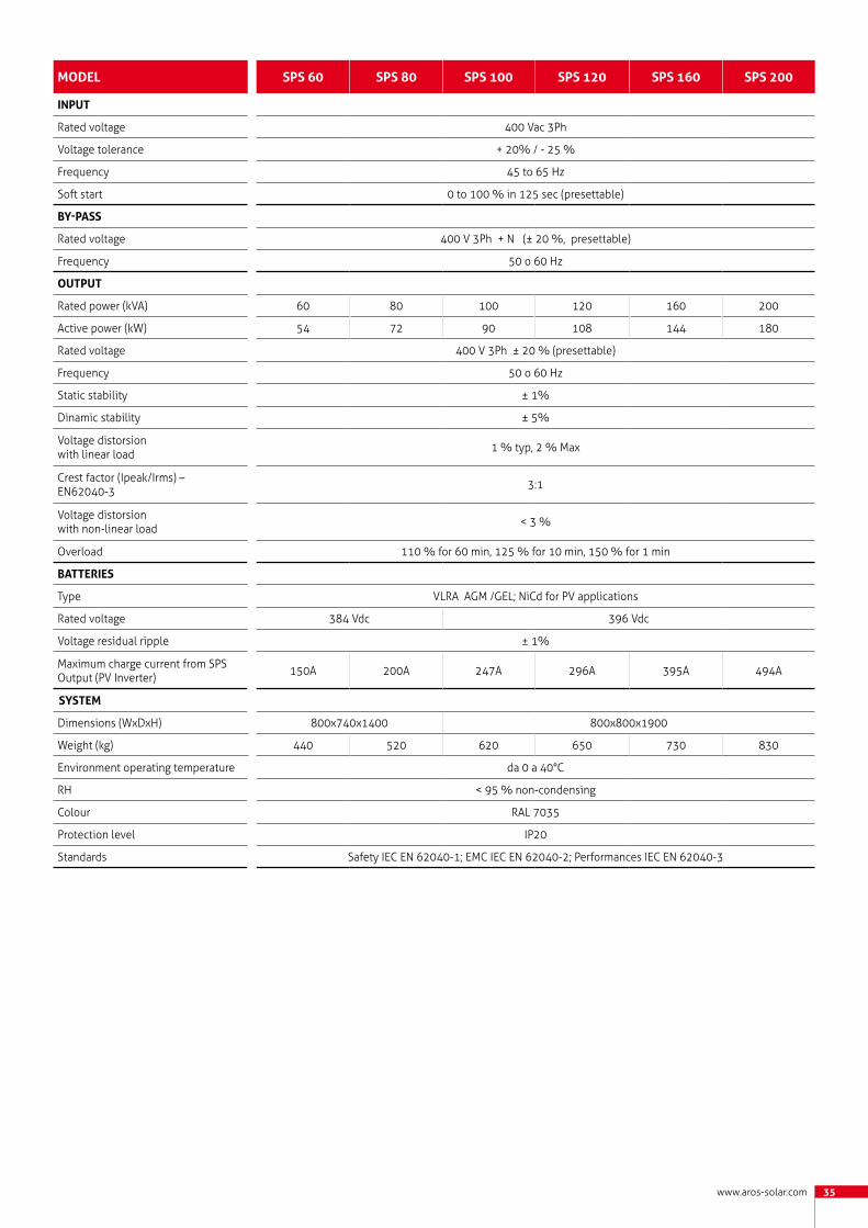
MoDel sps60 sps80 sps100 sps120 sps160 sps200
INput
Rated voltage 400 Vac 3Ph
Voltage tolerance + 20% / - 25 %
Frequency 45 to 65 Hz
Soft start 0 to 100 % in 125 sec (presettable)
By-pass
Rated voltage 400 V 3Ph + N (± 20 %, presettable)
Frequency 50 o 60 Hz
output
Rated power (kVA) 60 80 100 120 160 200
Active power (kW) 54 72 90 108 144 180
Rated voltage 400 V 3Ph ± 20 % (presettable)
Frequency 50 o 60 Hz
Static stability ± 1%
Dinamic stability ± 5%
Voltage distorsion with linear load 1 % typ, 2 % Max
Crest factor (Ipeak/Irms) – EN62040-3 3:1
Voltage distorsion with non-linear load < 3 %
Overload 110 % for 60 min, 125 % for 10 min, 150 % for 1 min
BATTErIES
Type VLRA AGM /GEL; NiCd for PV applications
Rated voltage 384 Vdc 396 Vdc
Voltage residual ripple ± 1%
Maximum charge current from SPS Output (PV Inverter) 150A 200A 247A 296A 395A 494A
systeM
Dimensions (WxDxH) 800x740x1400 800x800x1900
Weight (kg) 440 520 620 650 730 830
Environment operating temperature da 0 a 40°C
RH < 95 % non-condensing
Colour RAL 7035
Protection level IP20
Standards Safety IEC EN 62040-1; EMC IEC EN 62040-2; Performances IEC EN 62040-3

36

www.riello-ups.com 37
Software and monitoring solutions

38
SunVision 2Monitoring prograM
Configuration and monitoring solutions
AROS Solar Technology offers the ideal solution to guarantee a protected, efficient and global system combining Sirio inverters with software designed to ensure the complete control of your plant.
SunVision 2 can monitor up to 255 elements (Inverter or StringBox) grouped up to a maximum of 64 systems. The graphical display of electrical data provides customers with a clear overview of system status and produced energy values, a calculation of the reduction of CO2 emissions and the economic returns generated are always available thanks to special counters.SunVision 2 informs constantly the user about the status of the inverters, StringBox or environment sensors, either locally or sending messages over the network. Furthermore it’s possible to define a users list who will receive alarm notification by e-mails, faxes, SMS or voice messages. Appropriate graphical reports allow you to monitor daily, weekly, monthly and annual energy production. The new export routine to text format allows the use of data in various software applications for the management of subsequent statistical analysis.
Main features• Graphic monitoring of inverter status in real time• detailed view with all electrical data• centralised control of inverters connected
via serial port (RS232 or RS485) or via network• inverter, StringBox or system summary
display modes• graphical visualization tool for data log
monitoring• alarm notification by e-mail, fax or text
message• multilingual support• compatible with String Box• compatible with the environmental sensors
connected to the network via NetMan Sensor Interface• on-line help• data log import utilities from the previous
version of SunVision
Supported operating systemsWindows 7Windows Server 2008Windows VistaWindows 2003Windows XPWindows 2000

www.riello-ups.com 39
Sirio Data Control Monitoring prograM
Sirio Data Control was developed with the aim of simplifying the configuration of controlled devices as much as possible without compromising the main function of a program–which is supervising and monitoring devices on a LAN or through Internet up to a maximum of 300 inverters.
The graphical user interface of the Sirio Data Control has been designed to be as simple and intuitive as possible, showing all the available measurements and all the historic data of each inverter at the same time. Unlike the SunVision 2, the Sirio Data Control recovers any missing historical data from the apparatuses without the limitation of having the software always running on a dedicated PC.
Sirio Data Control also enables the user to remotely send control commands (like switching on/off, management of the active and reactive power, soft starts) to the inverter in the field.
NOTE: Compatibility is guaranteed with centralised inverters having firmware display 1.2.5 or later and with TL inverters. (EASY and EVO) with NetMan 204 Solar network card
Main features• Monitoring AROS inverter both on LAN and
through Internet• sending control commands to an individual
inverter or to the entire PV plant• optionally displaying the system’s
productivity in full screen mode (for example for large monitors in large scale installations or public administrations)
• simple and self-explanatory buttons• scanning the LAN and automatically adding
the inverter without user intervention• assigning the addresses without using the
DHCP server• real-time measurement of each inverter• synchronising the inverter’s date/time with
the pc
Supported operating systemsMicrosoft WindowsLinuxMac OS X

40
PV Configurator 2.0inVErtEr SELECtion SoftwarE
Identifying the most suitable inverter for the plant being constructed is an essential phase because doing so can prevent future technical problems. The PV Configurator 2.0 is a useful, quick and efficient on-line software that guides you in a few easy steps toward the optimal product choice for your residential or industrial plant, helping you to optimise energy production and, therefore, your earnings.
Main features• On-line application• updated photovoltaic module database• complete range of Sirio inverters• quick search function for optimal configuration (by power or number of panels) • creation of a report of the selected configuration• multilingual support

www.riello-ups.com 41

42
String Box
The String Box monitors the currents in photovoltaic modules and can promptly diagnose faults. The device is made of UV-resistant polyester resin and offers IP65 degree of protection. It has a general circuit breaker, type ABB T1D 160PV, to disconnect the photovoltaic field from the inverter and up to 16 strings (with a maximum input current per string of 9A) can be connected. Since it is compatible with the SunVision monitoring software, signals and alarms are sent in the event of current faults according to the thresholds set at configuration.Communication solutions include an RS485 and RS232 ports (supplied as standard), an optional slot for a NetMan Plus PV Ethernet card and analog inputs for the connection of environmental sensors (temperature, radiation and wind).
Main Features• Parallel connection of (up to) 16 strings by
9A each (8 channels)• local and remote indication of status and
alarm conditions• RS232 and RS485 connections supplied as
standard• one slot connection for expanding
communication (e.g. Ethernet board)• proprietary communication protocol and
MODBUS RTU, both available on all the communication ports• wide configurability of the monitoring
parameters using the available software• local history log of alarms and status• protection fuses for each couple of inputs,
1000Vdc on positive and negative• for each input is possible to connect wires
up to 16mm2• output switch, with optional release coil,
used for inverter detachment• monitored discharger, used against over-
voltage situations, protected against over-currents, easy to restore thanks to removable cartridges
• direct input power from PV field or from auxiliary
• insulated digital inputs for local monitoring• insulated analog inputs for environmental
sensors (2xPT100, 0-10V, 4-20mA)• configurable digital outputs with free
contacts• IP65 protection degree for external
environment.
Accessories

www.riello-ups.com 43
String Box Setup
Power Reducer KitSelf-conSumption SolutionS
This application is used to set the String Box depending on the features of the installation and the user’s requirements. Items that can be set are the analog inputs, digital inputs and outputs, read channels and alarm thresholds.
Main features• Via Time Windows function, time windows can be set for each of the 8 inputs necessary to avoid false alarms (e.g. in case of systematic shading out in certain periods and at certain times of the year)• configuration of the relays present on the device depending on status of the alarms• configuration of the two inputs 4/20 mA and 0/10 V• full management of the minimum alarm threshold parameters• management and download of the events log
In some cases the mains supply cannot accept the power generated by the photovoltaic stations but the user wishes to reduce his energy costs by installing a PV field with the intention of using all the produced energy. To adhere to contractual limitations and not supply energy to the grid, AROS Solar Technology recommends the addition of the “Power Reducer” Kit which forces the inverter to produce only the power required to supply the connected loads.
Main features• Compatible with the Sirio EASY, Sirio EVO and Centralised inverters• kit comprising of: - RS485 card (only for Central and Sirio Easy inverters, not required for Sirio EVO) - power meter (modular digital multimeters with multilingual graphic LCD
and RS485 output port) - amperometric transformers rated based on the load.
Note: See the functioning circuit diagram on page 58

44
NetMan 204 Solar
RS485
nEtwork agEnt
communication adapter
The NetMan 204 Solar board allows the management of a inverter directly linked to a 10/100 Mb LAN with standard network protocols (TCP /IP, HTTP HTTPS, SSH, SNMPv1 and SNMPv3).
Main features• 32bit RISC processor• 10/100 Mbps Ethernet and IPv4/6 compatible• SunVision2 and SirioDataControl compatible• Self-consumption monitoring and management• SNMP v1 with RFC3433 for environment sensors management • HTTP and HTTPS for Inverter management through web browser• SMTP for alarms and status messages e-mail delivery• ModBUS TCP/IP• Datalogger for event storage (30 years).• Wake on LAN management for TCP /IP network startup• Other standards: DHCP, DNS, FTP, NTP, ICMP , IGMP• Firmware update through network • Micro USB port
Note: accessory compatible with all the PV Inverter series
The RS485 card enables the creation of a BUS to connect additional inverters, displaying all parameters via connection to a PC equipped with SunVision software.
Main features• Plug & Play installation• data transfer up to 9.6 KBa
Note: accessory compatible with Sirio EASY and Central series

www.riello-ups.com 45
ModCOM PV
Solar View
modbuS protocol converter
data acquiSition device
ModBUS is an open-source and royalty-free serial communication protocol, which has become an industry standard in recent years thanks its ease of use and implementation. The ModCOM PV device makes it possible to monitor AROS photovoltaic inverters via the ModBUS RTU protocol over half-duplex RS-485 serial cable.
Main features• ModBUS/JBUS port can be configured as RS232 or RS485• RJ-45 connector for connecting to the ModBUS network• can be integrated with the main BMS management programs• LED signals for communication activity• firmware upgradeable through serial port
Note: accessory compatible with Sirio EASY and EVO. For Central series needed for ModBUS/RTU (standard for ModBUS/TCP)
This remote data acquisition device is capable of providing the main electric parameter information for a photovoltaic generator via an RS485 connection. By simple touch on the touch screen display , you can recall such values as panel voltage, power generated by the plant, line voltage and line current, energy produced and the amount of CO2 unemitted. In addition, an intuitive horizontal bar indicates the percentage of instant power. Touch screen technology makes it possible to scroll through and zoom in on graphics created by the device directly on the display. Compatible with installations of up to 5 inverters, it does not require special configurations since it is capable of automatically detecting the model and related characteristics of the inverters.
Main features • B/W 240x128 pixel LCD touch screen with LED backlight• RS485 and USB communication ports• multimedia graphic interface• 12Vdc power supply
Graphics• 5 display settings: 6-hour, 12-hour, 24-hour, weekly, and monthly• ability to display averages or individual readings

46
LIGHTING GRIDPOWERPLUGSTABLET COMPUTER
SMART PHONE
ROUTER ADSL
SMART TV
Power
Warning Alarm
EVO
SWITCHBOARD
TA
RCB SUNGUARD METER
SUNGUARD BOX
SUNGUARDSENSOR BOX
SUNGUARDSTRING CONTROL
METER
INVERTER
The SunGuard Energy Touch is an easily installable monitoring system for single-phase and three-phase systems. It monitors the progress of the consumption in relation to the energy produced, supplied and drawn.The SunGuard Energy Touch kit includes a SunGuard Box Wi-Fi datalogger, a bi-directional SunGuard Meter analyser with TA included and a SunGuard ready 7” Wi-Fi touch display.
The SunGuard Box datalogger must be connected to the bi-directional network analyser and the inverter and a simple configuration must be done. After alignment with the energy values of the production and the exchange meters, the system is ready for use.
The following optional monitoring tools can also be connected to the SunGuard Box datalogger for a more professional monitoring system:• SunGuard Sensor Box, with the irradiance
and temperature sensors to monitor environmental parameters that determine the energy production and performance levels of the PV plant;
• String Box or the SunGuard String Control to monitor the direct current of each individual photovoltaic string.
Sunguard Energy touch
SunGuard Monitoring solutions

www.riello-ups.com 47
SunGuard Box Energy Touch Wi-FiDatalogger Wi-Fi complete with power supply, high reception antennae, two serial RS232/RS485 converters with screw connectors and Ethernet port. Has 4Gb of memory to collect twenty years of historical data. Connected directly to the inverter and the SunGuard Meter via a double pole wire and transmits data to the Wi-Fi display.
SunGuard Meter (available in single-phase and three-phase versions with TA included) Compact and multifunctional analysers to be used in single-phase and three-phase systems. Displays the principal sizes of an electricity transmission grid, including the metering of fed and stored energy through an elegant, back-lit display. Have current transformers with integrated connection cables (1.5 mt). Do not require any setting since they are preconfigured. Have been designed considering certain aspects that are important to the installer such as: practicality, speed of installation and compact size. There are 3 different versions: 30 A single phase (for PV plants that are about 6 kW), 63 A three-phase (for PV plants that are about 30 kW) and 125 A three-phase (for PV plants that are about 60 kW).
SunGuard display 7” Wi-Fi Touch ScreenThe touch display allows the development of energy in the photovoltaic system to be controlled at a glance. Has been designed for all kinds of users and has undergone rigorous usability tests. Has four screens to provide different functions and alternative representations of the progress of the photovoltaic system. It is possible to view data that is instantly updated after a few seconds or historical values for the last twenty years. An indispensable instrument for all users of a photovoltaic system.
To make the monitoring system more complete and professional, SunGuard Energy Touch can be supplied with the following accessories:
• SunGuard Sensor Box (has a temperature and irradiance sensor): To monitor the environmental parameters which affect the production capacity. And the performance capacity of the PV plant;
• String Box or SunGuard String Control: To monitor the direct current of the photovoltaic strings.
Components
Optional components

48
Display Touch: control interface
USERS
The customer
The customer can monitor locally the real time or historic trends of the PV system via SunGuard Touch Display, PC (without installing any software), Smart TV, iPhone or iPad over Wi-Fi.The user will always know how much of the produced energy will be locally consumed or supplied and collected to/from the grid. This allows the user to analyze its energy balance to optimize the self-consumption.If internet connectivity is available, the user can access the SunGuard portal and activate the Web monitoring to set up messages and alarms, both by email and SMS.
Installers & companies
Using a specific key access the installer can monitor all PV systems equipped with a SunGuard Energy Touch connected to the Internet. The installer can continuously monitor the systems of its customers by offering a timely and high quality maintenance service.
Dealers & installers
Dealers can monitor via the web portal all PV systems where SunGuard Energy Touch is installed and connected to the Internet. This allows to leverage on a centralized system of monitoring so that reliable statistical analyses can be performed. They may require a complete customization of the Web portal to match the corporate image. They may also provide to the customers a direct access from their website, specifically connected to the SunGuard Web portal.
1
2
3
4
1. Instantaneous powerDisplay of consumed and generated power, management of power collected or fed from/into the public grid. At the bottom lies a horizontal bar that allows to control 24/7 when energy is supplied or collected to/from the public grid.
2. PV systemSection dedicated to PV system monitoring. It allows displaying the instantaneous power, the daily output and the energy produced in the last 30 days. The theoretical power (reference power of perfect efficiency of the system) is only available when using the SunGuard Sensor Box with radiation sensor.
3. Energy trackingEnergy produced, consumed, collected, supplied and self-consumed can be compared on daily, monthly or yearly basis. Top figure shows the totals of the five energies aligned with fiscal meters.
4. Daily budgetEasy and intuitive chart to monitor energy consumption or supplied/collected to/from the grid.
Other interfacesIn addition to the touch display supplied, other instruments area available to access the monitoring interface: Windows, Linux or Mac PCs or any other computing systems with any browser (no other software installation is required); Smart TVs & SunGuard web portal interface (only for SunGuard dataloggers connected to the Internet).

www.riello-ups.com 49
The WEB Portal
Monitoring interface for PV systems Energy Control interface for power consumption monitoring
In case of availability of an internet connection the user can register at the Web portal SunGuard (www.sunguard.it) and log in with a single account to monitor trends in production and consumption of one or more photovoltaic systems. In addition, user can activate failure alarms and generation messages. Messages can be delivered by SMS and email. The user can set telephone numbers and email addresses for message and alarm delivery.
Why register to SunGuard web portal?Although the SunGuard Energy Touch is designed to get under control the energy production and consumption of the local system on which it is installed (without internet connection), it is strongly advised to also use the SunGuard web portal. The SunGuard web portal provides a historical archive on line and allows to receive failure alerts and messages related to the system performance, by mail and SMS. The service requires for the payment of an annual license.
Portal services• Online support and telephone support• Data archive• Alarms and messages delivery through
mail and SMS• Monthly Reports in PDF for download• App for iPhone and iPad• Analysis and comparison of two or more
variables• Data download• Production estimates control for 20 years
After a quick setup you can to monitor instantly and historically (both numerically and graphically) the following information: power output, power consumption, supplied power, collected power, self-consumed power, energy produced, energy consumed, supplied energy, collected energy, self-consumed energy.It is possible to align the SunGuard Energy Touch values to reported values by the fiscal meter for production and exchange.
The local interface can be accessed via any computer equipped with a “network adapter” or a Wi-Fi link.To gain access to the Internet ,SunGuard Box datalogger needs to be connected through a network cable or a local Wi-Fi router. ADSL, UMTS and GPRS routers as well as SunGuard ready Access Points (compatible and preconfigured) are availa-ble through AROS Solar Technology web portal.
Data transmissionMonitored data

50
SunGuardMonitoring prograM
Everyday more and more photovoltaic systems, both civil and industrial, are installed without providing for adequate maintenance. Technological systems, above all when undergoing significant development, require routine and special maintenance operations to be carried out by specialised technicians. This, however, does not guarantee the complete and constant efficiency of the photovoltaic system and, even less, preventive interventions in the case of imminent energy loss or malfunction due to exogenous and/or endogenous causes. That’s why SunGuard has been developed.
A professional system that closely monitors every type of photovoltaic system, as well as the environment in which it is installed. Useful for smaller installations, necessary for medium to large sized installations. SunGuard communicates data and information in real time to both the operators who perform the monitoring, as well as to the specialised technicians, thereby allowing for targeted, timely and preventive interventions. SunGuard provides for the real time monitoring of the systems’ performance and, through the SunGuard Box interface, sends the data to the central calculation unit over an SNMP Protocol. The elaboration of this data, in addition to that which is received from weather stations, pyranometers, toroids and video cameras positioned upon the system, provides for the constant supervision of our systems and allows us to offer a service which is even more oriented towards maximum customer satisfaction.
Technical characteristics summary• Remote web-based management through
UMTS, GPRS, LAN network and Wi-Fi connectivity;
• monitoring of each individual inverter;• connection to every type of environmental
sensor;• numerical and graphical display of the
periodic data and reports regarding the system’s productivity;• notifications sent by email and SMS;• pro-active management of maintenance
interventions;• web-based system management for the
installers, maintenance personnel, technical assistance, help desk and final customer, through dedicated administration panels.
Main functions• Centralised multi-system management• multi-user functionality with various access levels• data storage in SQL databases• advanced formula editor• events and actions management• reporting system• performance analysis• graphics management• integrated video camera management• SNMP standard for extended monitoring• access to data collected

www.riello-ups.com 51
SunGuard Box Home
SunGuard Box Home Wi-Fi
datalogger
datalogger
For PV plants up to 20kWp with single inverter
Main features• Plant compatibility: 1÷20kWp• Number of monitorable inverters: 1• Power supply: 5Vdc/10W wallmount included• RS232/485 converter included• Operating range: 5÷50°C• RAM: 128Mb• Memory: 4Gb• Communication ports: 2 RS232, 1 RJ45 Ethernet
For PV plants up to 20kWp with single inverter
Main features• Plant compatibility: 1÷20kWp• Number of monitorable inverters: 1• Power supply: 5Vdc/10W wallmount included• RS232/485 converter included• Operating range: 5÷50°C• RAM: 128Mb• Memory: 4Gb• Communication ports: 2 RS232, 1 RJ45 Ethernet
SunGuard Box Familydatalogger
For PV plants up to 20kWp, no limit for invertersMain features• Plant compatibility: 1÷20kWp• Power supply: 5Vdc/10W wallmount included• RS232/485 converter included• Operating range: 5÷50°C• RAM: 128Mb• Memory: 4Gb• Communication ports: 2 RS232, 1 RJ45 Ethernet

52
SunGuard Box Small
SunGuard Box Professional
datalogger
datalogger
For PV plants up to 100kWp
Main features• Plant compatibility: 1÷100kWp• Power supply: 24Vdc/60W DIN included• Terminal board: MOXA type for DB9 connectors (RS485) included• Operating range: -20÷60°C• RAM: 64Mb• Memory: 4Gb• Communication ports: 1 RS232, 3 RS485, 2 RJ45 Ethernet
For PV plants up to 500kWp
Main features• Plant compatibility: 1÷500kWp• Power supply: 24Vdc/60W DIN included• Terminal board: MOXA type for DB9 connectors (RS485) included• Operating range: -20÷60°C• RAM: 64Mb• Memory: 4Gb• Communication ports: 1 RS232, 3 RS485, 1 RJ45 Ethernet
SunGuard Box Family Wi-Fidatalogger
For PV plants up to 20kWp, no limit for inverters
Main features• Plant compatibility: 1÷20kWp• Power supply: 5Vdc/10W wallmount included• RS232/485 converter included• Operating range: 5÷50°C• RAM: 128Mb• Memory: 4Gb• Communication ports: 2 RS232, 1 RJ45 Ethernet

www.riello-ups.com 53
SunGuard String Control Kitcurrent SenSor
SunGuard Box Businessdatalogger
For PV plants over 500kWp
Main features• Plant compatibility: >500kWp• Power supply: 24Vdc/60W DIN included• Terminal board: MOXA type for DB9 connectors (RS485) included• Operating range: -20÷60°C• RAM: 1Gb• Memory: 4Gb• Communication ports: 2 RS232, 2 RS485, 2 RS485 optoisolated, 3 RJ45 Ethernet
Available versions• SGK-16 for 16 strings• SGK-12 for 12 strings• SGK-8 for 8 strings• SGK-4 for 4 strings
The kit comprises of a master card to which the following monitoring tools can be connected:
- from 1 to 4 slave cards with 4 Hall effect sensors for a total of 16 channels;- up to two 0-100mV irradiance sensors supplied with calibration certificates;- up to four 2-4 string PT100 or PT1000 temperature probes;- an anemometer to monitor wind speed.
Main features• Monitoring from 1 to 1016 strings• From 0 to 50 Ampere for string• ModBUS communication• RS485 connection• 24Vdc power supply

54
SunGuard Sensor KitEnVironMEntaL SEnSorS
Available versions
• SensorKit-A
• SensorKit-B
Main features• Kit-A: irradiance and temperature module sensor• Kit-B: irradiance sensor, module temperature, environment temperature and anemometer• Power supply: 24Vdc from SunGuard Box• ModBUS communication• RS485 connection
Irradiance sensor EnVironMEntaL SEnSorS
Compatible with String Box too
Main features• Measurement range: 0÷1500 W/m2• Sensor type: monocrystalline cell (33mm / 50mm)• Sensor accuracy: ± 5% yearly average• Electrical output: 4÷20 mA or 0÷10 V or 0÷3.125 V or 0÷150 mV• Consumption: C. 30 mW• Connection type: connection terminals, 1.5 mm²• Dimensions: 150x80x60 mm (WxDxH)• Weight: 700 g
PV module temperature sensor EnVironMEntaL SEnSorS
Compatible with String Box too
Main features• Measurement range: -20÷150°C• Sensor type: platinum resistance wire• Electrical output: PT100• Cable: 3 mt, connection with 3 conductors• Mounting: tape (included)• Dimensions: 50x50x1 mm (WxDxH)

www.riello-ups.com 55
Anemometer EnVironMEntaL SEnSorS
Main features• Measurement range: 2÷200 Km/h• Sensor accuracy: ±2%• Cable: 15 mt • Mounting: steel bracket included• Dimensions: 123x138,5 mm (DxH)
Environment temperature sensor PT1000 EnVironMEntaL SEnSorS
Main features• Measurement range: -20÷200°C• Sensor type: platinum resistance wire• Electrical output: PT1000• Cable: 2,5 mt, connection with 2 conductors• Mounting: hole for mounting with screw included • Dimensions: 52x50x32 mm (WxDxH)
Environment temperature sensor PT100EnVironMEntaL SEnSorS
Main features• Measurement range: -35°C÷90°C• Protection level: IP66• Electrical output: PT100• Dimensions: 50x52x35 mm (WxDxH)

56
LED Displayfor ExtErnaL EnVironMEnt
Main features• Visualization: 2-line, 16 alphanumeric characters• Tipology: pages or scrolling (max. 512 scrolling characters)• Management: via RS485 to the network analyzer or LAN Ethernet• Supply: 220 V/50 Hz• Dimensions: 1500x75x700 mm (WxDxH)• Weight: 15 Kg
Available versions
• LED display
• LED display with network analyzer
Modem Router 3G HSPA
Main features• 3G Wireless Router• HSPA+ 21,6Mbps Download, 5.76Mbps Upload• UMTS 2100MHz, GSM 850/900/1800/1900MHz• Wireless 802.11n 300Mbps a 2.4GHz• 4 ports LAN RJ45 10/100Mbps• 1 port RJ11, 1 port USB 2.0, 1 slot for USIM
Note: The client must provide the device with a DATA SIM from a selected telephone operator. This is required for it to work properly.
Main features• Power supply: 5Vdc/10W wall mount included• Operating range: 5°C–50°C• Communication interfaces: 1 RJ45 Ethernet, 2 RS232, VGA port
SunGuard Video DisplaySignal Splitter for video SyStemS
Available versions• SunGuard Video Display
• SunGuard Video Display Wi-Fi
The SG-VIDEO-DISPLAY is connected to a monitor with a VGA port and the internet, it allows display with cyclical trend (about 5 seconds), the various trend-related slides of one or more photovoltaic systems monitored with the SunGuard monitoring system. The data displayed on the monitor are as follows: daily production, total production, saved trees, barrels of equivalent petroleum, weekly production, monthly production, avoided CO2 emissions, instantaneous power.

www.riello-ups.com 57
LoCaL Monitoring
Sub-field 1
String Box
Sub-field 2
String Box
String Box
Sub-field n
Irradiance sensor
PV module temperature sensor
NetMan Plus PV
NetMan Plus PV
NetMan Plus PV
Hub RouterADSL
SoftwareSUNVision
Local Workstation
SoftwareSUNVision
Remote Workstation
Power
Warning Alarm
EVO
Power
Warning Alarm
EVO
Power
Warning Alarm
EVO
Power
Warning Alarm
EVO
Solar View
or
BUS 485AdapterRS485/USBRS485/RS232 Software
SUNVision
Local Workstation
Monitoring oVEr Lan
Sub-field 1
String Box
Sub-field 2
String Box
String Box
Sub-field n
Irradiance sensor
PV module temperature sensor
NetMan Plus PV
NetMan Plus PV
NetMan Plus PV
Hub RouterADSL
SoftwareSUNVision
Local Workstation
SoftwareSUNVision
Remote Workstation
Power
Warning Alarm
EVO
Power
Warning Alarm
EVO
Power
Warning Alarm
EVO
Power
Warning Alarm
EVO
Solar View
or
BUS 485AdapterRS485/USBRS485/RS232 Software
SUNVision
Local Workstation

58
Sunguard Solar management monitoring
power reducer Kit
Power
Warning Alarm
EVO
Sub-field 1
String Box
RS 485
Sub-field 2
String Box
RS 485RS 485
RS 4
85Et
hern
et
Sub-field nString Control
Irradiance sensor
PV module temperature sensor
Sensor Kit
Display LCD
SunGuardBox
SunGuardSolar Management
Remote Workstation
PV systems
RS 485
Power meter
Inverter SIRIO
Load

www.riello-ups.com 59

60
323
560
323 323
127.5
424
630 682
424
612
173.5
742
533
670
533
224
670
325
325
555 590 532
168.5
TL INVERTERS
Sirio EASY 1500 / 2000 / 3000
Technical data
Sirio EVO 5000 / 6000 Sirio EVO 10000 / 12500
Sirio EVO 1500 / 2000 / 3000 / 4000

www.aros-solar.com 61
% of Rated Input Power
Effici
ency
%
99
97
95
93
91
89
87
85
83
810 20 40 60 80 100
% of Rated Input Power
99
97
95
93
91
89
87
85
83
810 20 40 60 80 100
% of Rated Input Power
99
97
95
93
91
89
87
85
83
810 20 40 60 80 100
Vin= 250V
Vin= 370V
Vin= 425V
FEATURESColour: RAL 3020Protection level: IP20 (indoor)Acoustic noise: <35dBA
FEATURESColour: RAL 3020Protection level: IP65Acoustic noise: <35dBA
FEATURESColour: RAL 3020Protection level: IP65Acoustic noise: <35dBA
Sirio EASY 1500 / 2000 / 3000
Sirio EVO 1500 / 2000
Sirio EVO 3000 / 4000
% of Rated Input Power
Effici
ency
%
99
97
95
93
91
89
87
85
83
810 20 40 60 80 100 120
% of Rated Input Power
99
97
95
93
91
89
87
85
83
810 20 40 60 80 100 120
Vin= 350VVin= 450V
Vin= 600V
Vin= 350VVin= 450V
Vin= 600V
99
97
95
93
91
89
87
85
83
810 20 40 60 80 100 120
% of Rated Input Power
99
97
95
93
91
89
87
85
83
810 20 40 60 80 100 120
% of Rated Input Power
Effici
ency
%

62
FEATURESColour: RAL 3020Protection level: IP65Acoustic noise: <35dBA
FEATURESColour: RAL 3020Protection level: IP65Acoustic noise: <35dBA (<45dBA with fans running)
Sirio EVO 5000 / 6000
Sirio EVO 10000 / 12500
Vin= 400VVin= 615V
Vin= 750V
Vin= 350VVin= 450V
Vin= 600V
99
97
95
93
91
89
87
85
83
810 20 40 60 80 100 120
% of Rated Input Power
Effici
ency
%
99
97
95
93
91
89
87
85
83
810 20 40 60 80 100 120
% of Rated Input Power
100
98
96
90
94
92
88
860 20 40 60 80 100 120
% of Rated Input Power
Effici
ency
%
0 20 40 60 80 100 120
% of Rated Input Power
100
98
96
90
94
92
88
86

www.aros-solar.com 63
CENTRAL INVERTERS
Sirio K12 / K15 / K18
Sirio K64 / K80 / K100 / K64 HV / K80 HV / K100 HV
Sirio K25 / K33 / K40 / K25 HV / K33 HV / K40 HV
Sirio K200 / K200 HV / K250 HV
997
13
1630
1010
1630 1630
1900
1400
555
750 740
10
555555
1400
555
750 740
10
555555
1900
800800
800
797
13
810

64
FEATURESColour: RAL 7035Protection level: IP20Acoustic noise: <66dBA
FEATURESColour: RAL 7035Protection level: IP20Acoustic noise: <66dBA
FEATURESColour: RAL 7035Protection level: IP20Acoustic noise: <66dBA
Sirio K12 / K15 / K18
Sirio K25 / K33 / K40
Sirio K25 HV / K33 HV / K40 HV
% of Rated Input Power% of Rated Input Power% of Rated Input Power
Effici
ency
%
400 Vdc
400 Vdc
530 Vdc
% of Rated Input Power % of Rated Input Power% of Rated Input Power
Effici
ency
%
% of Rated Input Power % of Rated Input Power% of Rated Input Power
Effici
ency
%

www.aros-solar.com 65
Sirio K64 / K80 / K100
Sirio K64 HV / K80 HV / K100 HV
Sirio K200 / K200 HV / K250 HV
FEATURESColour: RAL 7035Protection level: IP20Acoustic noise: <68dBA
FEATURESColour: RAL 7035Protection level: IP20Acoustic noise: <68dBA
FEATURESColour: RAL 7035Protection level: IP20Acoustic noise: <72dBA
530 Vdc
400 Vdc
% of Rated Input Power % of Rated Input Power% of Rated Input Power
Effici
ency
%
% of Rated Input Power % of Rated Input Power% of Rated Input Power
Effici
ency
%
% of Rated Input Power % of Rated Input Power % of Rated Input Power
Effici
ency
%
400 Vdc 530 Vdc 530 Vdc

66
HV-MT CENTRAL INVERTERS
Sirio K100 HV-MT
Sirio K330 HV-MT / K500 HV-MT
Sirio K200 HV-MT / K250 HV-MT
Sirio K800 HV-MT
1900
800800
800
797
13
810
1630
997
13
1010
1630 1630
1900
1500
997
13
1010
1500 1500
1900
2100
2100
2100
1900
1010997
13

www.aros-solar.com 67
% of Rated Input Power
Effici
ency
%Sirio K100 HV-MT
Sirio K200 HV-MT / K250 HV-MT
Sirio K330 HV-MT / K500 HV-MT and K800 HV-MT
FEATURESColour: RAL 7035Protection level: IP20Acoustic noise: <68dBA
FEATURESColour: RAL 7035Protection level: IP20Acoustic noise: <72dBA
FEATURESColour: RAL 7035Protection level: IP20Acoustic noise: <72dBA
530 Vdc
530 Vdc% of Rated Input Power% of Rated Input Power
Effici
ency
%
% of Rated Input Power% of Rated Input Power
Effi
cien
cy %
530 Vdc

Operating Offices
RPS S.p.A.
ITALY
LEGNAGO (VR)Head OfficeViale Europa, 7 37045 LEgnago (Verona) Tel +39 0442 635811Fax +39 0442 629098 www.riello-ups.com [email protected]
CORMANO (MI)Sales OfficeVia Somalia, 2020032 Cormano (milano)Tel +39 02 663271Fax +39 02 66327351
ROMESales OfficeVia Fosso della magliana, 34/g00148 romETel +39 06 65192125Fax +39 06 65192247
PRE-SALES SUPPORT (TEC)[email protected]
AFTER-SALES SUPPORT (UPService)[email protected]
68
UNITED KINGDOM
RIELLO UPS Ltd. Unit 50 Clywedog road northWrexham Industrial EstateWrexham LL13 9XnTel +44 800 269 394Fax +44 1978 729 290
CONSTANT POWER SERVICES Ltd.riello House, Works road, LetchworthSg6 1aZ HertfordshireTel +44 330 1230125Fax +44 1462 422754
GERMANY
RIELLO UPS GmbHWilhelm-Bergner-Str. 9b21509 glindeTel +49 40 / 527 211-0Fax + 49 40 / 527 211-200
RIELLO POWER SYSTEMS GmbHneufahrner Str. 12b85375 neufahrn/grüneckTel +49 8165 / 9458-0Fax +49 8165 / 9458-26
FRANCE
RIELLO ONDULEURS S.a.r.l.2/4 rue du Bois Chaland,ZaC du Bois Chaland 91090 LissesTel +33 1 60 875454Fax +33 1 60 875450
Agence Rhone Alpes - Sud147 avenue m. mérieux,Parc de Sacuny, Park avenir 169530 BrignaisTel +33 4 72 177108Fax +33 4 78 351422
SPAIN & PORTUGAL
RIELLO TDL s.l. (Solar Division) C/ Berguedà, 6 bis - Pol.Ind. Plà de la Bruguera08211 Castellar del Vallès, BarcelonaTel.: +34 (0)93 74 71 210Fax: +34 (0)93 71 46 562
ROMANIA
S.C. Banattika S.r.l. (Riello UPS Romania) Str. Varsovia nr. 4307160 DumbravitaTimis County - romaniaTel +40 256 214 681Fax +40 256 214 682
AUSTRALIA
RIELLO UPS AUSTRALIA Pty. Ltd. Unit 22/80 Box roadTaren Point nSW 2229 Tel +61 2 9531 1999Fax +61 2 9531 1988
Unit 17/810-818 Princes HwySpringvale VIC 3171 Tel +61 3 9574 6922Fax +61 3 9574 6933
Po Box 2251Yokine South Wa 6060Tel +61 1300 138,709
ASIA PACIFIC
RIELLO UPS SINGAPORE Pte Ltd.no. 506 Chai Chee Lane,#07-01, Singapore 469026Tel +65 6853 1190 Fax +65 6853 1176
CHINA
Riello UPS (Asia) Co., Ltd.Bolg2, no.451 Duhui road, minhang District-201108 ShanghaiTel +86 21 50464748Fax +86 21 50464648
Sales office Beijing Unit 3B,Building B, Jinyuan Century Business Centre, no.1, Yuanda road, Haidian District 100097 BeijingTel +86 10 82038861 / 8862 Fax +86 10 82038863
Sales office Guangzhouaddress Unit 1507 East Building,Dongshan Square, no. 65,Xianlie Zhong road, Yuexiu District510095, guangzhouTel +86 20 28848001Fax +86 20 28848002
Sales office Jinanroom 3508, Building2 Inzone Center, no.22799Jingshi road, JinanTel +86 531 87969877Fax+86 531 87960977 Sales office Xi’ana2604, oak Constellation , no. 3, Ke Ji 5th road,High-Tech Zone, Xi’anTel +86 29 89526941Fax+86 29 89526943 Sales office Chengdu room 1703, Level 17,Raffles City Tower 2, no. 3 Section 4,South renmin road, ChengduTel +86 28 6511 2870/71Fax+86 28 6511 8199
INDIA
RIELLO PCI India Pvt. Ltd. Prime Tower: 287-288Udyog Vihar, Phase II122015 gurgaon (Hr)Tel.: +91-124-6656999Fax: +91-124-4871698
www.riello-ups.com
Follow us on Social networks
69www.riello-ups.com

Notes
70

71www.riello-ups.com


General cataloGuePhotovoltaic> 2015-2016
RPS S.p.A. - Member of the Riello Elettronica Groupviale europa, 7 - 37045 leGnaGo (verona) - italyt +39 0442 635811 - F +39 0442 629098www.riello-ups.com - [email protected]
CAT
GEN
X0Y
15C
AGB