Gem Cut Studio
61
Gem Cut Studio User’s Manual V1.1.0 rev. 1
Transcript of Gem Cut Studio
Gem Cut Studio
User’s Manual
V1.1.0 rev. 1
Gem Cut Studio is a software application combining various tools for designing, visualizing, and optimizing gem cuts. The main focus of the application is to provide a real-time preview of any changes, enabling a speedy and well-informed workflow. This manual serves as both reference to the user interface as well as an explanation of typical user interactions by means of workflow examples. Please note that some interactions are best demonstrated in video tutorials, which are available here: Gem Cut Studio - Documentation and tutorials on YouTube (or search YouTube for “Gem Cut Studio Documentation”) This manual assumes the reader is familiar with gem cutting and understands basic gem cutting terminology.
1

Index
General notes 4
User Interface 4 Index Gear Settings 5 Mast Controls 7 Instructions View 8 Design View 10 Render View 12
Gem Properties 14 Material 14 Refractive Index 14 Dispersion 15 Stone Color 15 Clarity 15 Color Density 15 A note on defining gem colors: 15
Render Options 16 Low Resolution 16 High Resolution 17 # Bounces 17 Lighting Model 17
Random. 17 Angle Rings. 18 Isometric 18 Cosine 18
Background Color 18 Use Separate Window Color 18 Head Shadow Half-Angle 19 Head Shadow Color 19
Menu reference 20 File 20
New 20 Open… 20 Save 21 Save As… 21 Export… 21 Print… 21
Edit 23 Undo / Redo 23 Rotate by index 23
2
Reverse Index Order 23 Resize Girdle 23 Flip Crown-Pavilion 24 Scale X-Y 24 Scale Z (Tangent ratio) 24 Info / Comments… 25 Preferences… 25
View 26 All 26 Instructions / Design / Render 26 Fullscreen (Windows, Mac) 26
Tools 27 Tilt Performance 27 Manual Optimizer 29 Size / Yield Calculator 30 Light Path Viewer 31 Cutting Assistant 32
Design Workflow 33 Setting up a cut 33 Cutting a basic symmetric tier 36
Single Cut 36 Symmetric Cut 39 Mirrored Cut 40 Mirrored Symmetric Cut 41
Replicating a cut from an existing design 42 Adding meetpoints 45
Examples 47 Cutting the Standard Round Brilliant - Step by step 47 Optimizing an existing design for a different material 55
First method: Simple tangent ratio 55 Second method: Manual Optimizer 55
Tips and Tricks 56 Running out of material and “growing the gem” 56
Advanced topics 57 Adding and modifying materials 57 Adding lighting models 57 The .GCS file format 58
3

General notes Although Gem Cut Studio is a computer-aided design (CAD) application, the gem designs produced are dimensionless. That is to say that while maintaining proportions is critical when cutting the design, the actual size of the cut gem is irrelevant, as the design can scale to any size. For this reason, most dimensions discussed will be in terms relative to width, depth and height rather than a particular size in millimeters.
User Interface Gem Cut Studio’s main interface is divided into five parts:
There is also a menu at the top of the application (or in the menu bar on Mac) The Instructions View, Design View, and Render View can be maximized within the
application by clicking the square-shaped icon in each view’s upper right corner. Once maximized, more information will be displayed and advanced operations can be performed relating to that view. To return to the starting split view, click the square icon again. Note: Views can also be maximized / minimized through the View menu.
4

Index Gear Settings This is where values relating to index gear choice, base index, symmetry and mirroring are set.
On the leftmost side of the Index gear settings is a gear icon with a number inside representing the index gear currently selected for the design. Clicking on this icon opens the Change Index Gear popup:
When starting a new design, this can be used to set the index gear. The default gear is a 96 tooth but this can be changed by choosing a different value in the New index gear list. Ticking the Set as default for new designs box will use this index gear as default for all new designs going forward. When remapping an already loaded design to a different index gear, a new gear can be chosen from the list. Any number listed in white means the re-map can occur without modification to the design. Any number listed in red means some facets will either need to be rounded to the nearest index (with missed meets), or will appear as fractional index values in the instructions list. After selecting a red-listed gear as the target, a report showing how many facets would need to be corrected is displayed as well as two checkboxes giving the user the choice of how to deal with these facets. Ok confirms the change and Cancel exits without modification.
5

Next to the gear icon is a mode selector for the Index gear setup. By default, the view is set to the simple “Symmetrical” mode. By pressing the “Mode” button, this can be changed to “Arbitrary”. When in Symmetrical mode, ruler controls are used to set the base index, symmetry and mirror when adding or editing tiers.
Values can be changed by clicking, then dragging the ruler control left-right until the desired value is obtained. Values can also be set directly by first clicking inside the control, then typing in the value using the keyboard. With the mouse pointer hovering over a ruler, it’s also possible to change its value by scrolling the mouse wheel. More details on how to use these controls is given in “Setting up a cut”. In arbitrary mode, the base index / symmetry / mirror selectors are replaced by one large text field.
By typing index numbers in this field, and using the “-” (minus) character to separate entries, a custom set of index values can be set. This can be useful to replicate existing designs by simply typing in an existing index list, rather than trying to work out the tier’s symmetry. Arbitrary mode can also be used to create freeform designs while still making use of Gem Cut Studio’s powerful editing tools.
6
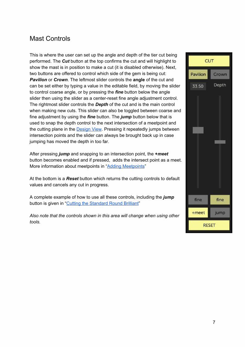
Mast Controls This is where the user can set up the angle and depth of the tier cut being performed. The Cut button at the top confirms the cut and will highlight to show the mast is in position to make a cut (it is disabled otherwise). Next, two buttons are offered to control which side of the gem is being cut: Pavilion or Crown. The leftmost slider controls the angle of the cut and can be set either by typing a value in the editable field, by moving the slider to control coarse angle, or by pressing the fine button below the angle slider then using the slider as a center-reset fine angle adjustment control. The rightmost slider controls the Depth of the cut and is the main control when making new cuts. This slider can also be toggled between coarse and fine adjustment by using the fine button. The jump button below that is used to snap the depth control to the next intersection of a meetpoint and the cutting plane in the Design View. Pressing it repeatedly jumps between intersection points and the slider can always be brought back up in case jumping has moved the depth in too far. After pressing jump and snapping to an intersection point, the +meet button becomes enabled and if pressed, adds the intersect point as a meet. More information about meetpoints in “Adding Meetpoints” At the bottom is a Reset button which returns the cutting controls to default values and cancels any cut in progress. A complete example of how to use all these controls, including the jump button is given in “Cutting the Standard Round Brilliant” Also note that the controls shown in this area will change when using other tools.
7

Instructions View
This area shows the cutting sequence instructions as they would appear on a printout. From here, the user can select tiers for editing or set tier properties like frosting. Each tier is represented by a separate line and can be selected by clicking on it. Clicking on the selected tier again removes the selection. To edit the tier description, click once anywhere on the tier line to select it, then click again anywhere inside the rightmost column, after the index list. This will allow for regular keyboard editing of the cutting instructions. Confirm by pressing ENTER on the keyboard or by clicking elsewhere in the application. If the cutting instructions are not visible or cut off, the Instructions View can be maximized by using the Instructions option in the View menu or
click the square-shaped icon in the Design View’s upper right corner. When a tier is selected, a tier menu appears at the bottom of the Instructions View. Using the menu buttons, different operations can be performed on the selected tier. Edit Tier: This operation will attempt to set the base index, symmetry, mirror, angle and depth to the values used to cut the tier. From here any of the variables can be changed and confirmed to cut the tier again. After going into edit mode on a tier, The reset button in the Mast View changes to a cancel button, which can be used to abort the edit operation and revert back to the original tier. If the selected tier cannot be re-created using the simple “Symmetrical” index / symmetry / mirror values - for example if the tier is the result of
8

merging arbitrary index values at the same angle and depth - the index mode will automatically be changed to “Arbitrary” and the index list populated with the list of index values from the original tier. Depth and angle can then be changed, and index values deleted or added to the index list by editing the string of values. Move Up / Move Down: This operation will move the tier in the cutting order. Because each cut is independent, this does not affect the final gem design. Re-ordering should be done to aid in cutting the gem, either by creating meet point sequence steps, or to avoid having to judge depth using gauges / eyes only. Note that tiers can also be re-ordered using “drag and drop” within the list. Show / Hide: This temporarily toggles the selected tier’s visibility and influence on the raytraced result. For example, when cutting a complex design in small-size rough, this can be used to evaluate the effect of not cutting a particular tier on cutting sequence, visual result, and performance. A tier that is currently hidden will appear as semi-transparent text in the instructions list. Delete Tier: This removes the tier from the instructions and removes and facets cuts as part of this tier. Preform: This marks the selected tier as a special “preform” tier, which is typically cut to assist in cutting other tiers by providing meet points, but doesn’t end up as part of the final design. By default, Gem Cut Studio will remove any tier whose facets get cut away by another tier, but if that tier is marked as preform, it will be shown in the instructions list regardless. Frosted: This toggles the frosting effect on the tier. Frosting is when a facet is cut up to a certain grit, but not polished. This can be used for artistic effect. To only frost certain facets within a tier, follow the instructions in the Design View operations.
9

Design View
This area shows a 3D model of the gem design in its current state. When setting up a cut, the Design View updates automatically to follow the effect of the cut in progress. The model shown can be rotated for viewing by first pressing and holding the left mouse button, then dragging the mouse in either direction. Double-clicking inside the Design View resets the rotation, depending on which side is currently set for editing in the Mast View. When the rotation is reset, a list of index values is also shown surrounding the design. The mouse wheel can be used to zoom in or out of the Design View. When starting a new design, a cube is shown to represent the starting rough. Cutting instructions required to cut this cube also appear in the Instructions View. Although the starting rough is a cube, any type of gem can be cut into the starting block. To aid visualization, the stone is re-scaled after each operation to fill the workspace. If a particular size block is required to assist in starting a design, the block can be changed to any ratio of Length, Width, and Height using the Set Starting Ratios... button in the lower right. The Add Meet button is explained in detail in the “Adding Meetpoints” section.
10
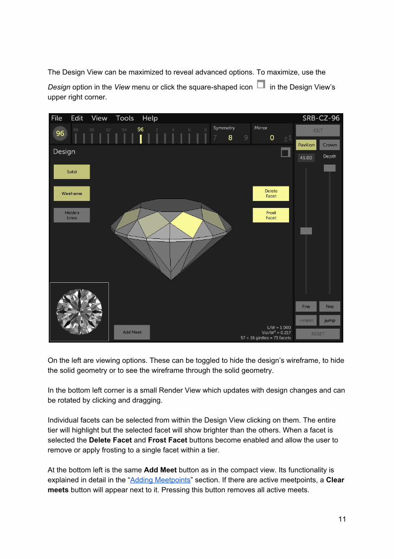
The Design View can be maximized to reveal advanced options. To maximize, use the
Design option in the View menu or click the square-shaped icon in the Design View’s upper right corner.
On the left are viewing options. These can be toggled to hide the design’s wireframe, to hide the solid geometry or to see the wireframe through the solid geometry. In the bottom left corner is a small Render View which updates with design changes and can be rotated by clicking and dragging. Individual facets can be selected from within the Design View clicking on them. The entire tier will highlight but the selected facet will show brighter than the others. When a facet is selected the Delete Facet and Frost Facet buttons become enabled and allow the user to remove or apply frosting to a single facet within a tier. At the bottom left is the same Add Meet button as in the compact view. Its functionality is explained in detail in the “Adding Meetpoints” section. If there are active meetpoints, a Clear meets button will appear next to it. Pressing this button removes all active meets.
11

Render View
This area shows a physical model of how the current gem design would look in real-life. Any time changes are made to the design, the Render View is updated automatically to show how those changes affect the final, cut gem. The Render View uses a technique called Raytracing. This computer graphics process is used to simulate complex light interactions in physical materials. In the case of Gem Cut Studio, this means taking into account the various parameters which define our gem material like index of refraction, dispersion, color, and more. While a raytrace is a physically accurate method, its scope is limited and can’t take into account all of the intricacies of light/material interactions as well as imperfections in natural materials. Therefore, while the Render View should give a very close approximation of what the final cut stone will look like, no guarantees are made about its accuracy. The rendered gem can be rotated for viewing by first pressing and holding the left mouse button inside the Render View, then dragging the mouse in either direction. Double-clicking inside the Render View resets the rotation to face-up view.. Information in the bottom-right corner shows the current rotation, refractive index, and dispersion. There is also a value for the critical angle calculated for the refractive index currently in use.
12

The Render View can be maximized to reveal advanced options. To maximize, use the
Render option in the View menu or click the square-shaped icon in the Render View’s upper right corner.
At the bottom-left are two sliders to control the gem’s rotation. These sliders can be used to set a particular tilt angle, for example when evaluating windowing or tilt brightness. Above the sliders are two buttons: The Save Image button captures a frame of the currently rendered gem to a PNG image file. Since the image is saved using the High Resolution (see below), the button may be disabled if the renderer has not yet produced the high resolution image. The Record Animation button is used to produce a freeform animation of the gem being rotated. When the button is first pressed, this “arms” the recording mode, but nothing is recorded yet. A red, static frame appears around the render area to indicate what will be captured. To begin recording, drag the rendered gem to rotate it, as described above. The red frame will then start blinking to indicate recording has begun. To stop recording, release the mouse button to stop drag-rotating. A popup will then ask where to save the GIF animation. After confirming filename and location, the software will go through and render each animation frame in high resolution to produce the final GIF (i.e.: the High Resolution value controls the animation size). This animation can then be shared by email, social media, website upload, etc. Keep in mind that animation files can grow quite large, so aim to use sensible resolutions and keep recording times as low as possible.
13
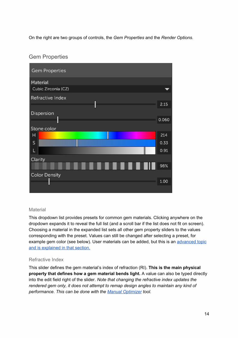
On the right are two groups of controls, the Gem Properties and the Render Options.
Gem Properties
Material This dropdown list provides presets for common gem materials. Clicking anywhere on the dropdown expands it to reveal the full list (and a scroll bar if the list does not fit on screen). Choosing a material in the expanded list sets all other gem property sliders to the values corresponding with the preset. Values can still be changed after selecting a preset, for example gem color (see below). User materials can be added, but this is an advanced topic and is explained in that section.
Refractive Index This slider defines the gem material’s index of refraction (RI). This is the main physical property that defines how a gem material bends light. A value can also be typed directly into the edit field right of the slider. Note that changing the refractive index updates the rendered gem only, it does not attempt to remap design angles to maintain any kind of performance. This can be done with the Manual Optimizer tool.
14

Dispersion This slider controls how light is scattered inside the gem, in relation to wavelength. Dispersion is evaluated by following three separate color rays instead of one. If this parameter is set to any non-zero value, performance will drop as the workload on the processor triples. A value can be typed directly into the edit field right of the slider.
Stone Color This controls the actual color of the gem shown in the Render View. Color is set using a set of sliders that control the hue (or “tint”), saturation (or color “depth”) and lightness. This method of defining color is more precise than typical Red / Green / Blue values but by clicking on the leftmost band of the color slider group (Where the “H” “S” “L” labels are shown), the control can be changed to RGB values.
Clarity This slider controls an approximation of the physical modelling of hazy gem materials. A value of 100% means full clarity (zero haziness). Haziness can be due to various factors in a gem material: microscopic inclusions, fractures, or others. Clarity simulates these by absorbing light, regardless of its direction and diffusing it back as general lighting, according to the gem color. This does not simulate the blurriness that is often associated with hazy materials and is considered an imprecise modeling technique, meant only as an aide.
Color Density This slider controls how quickly the gem gets dark, in relation to the distance travelled by the light ray inside the material. A higher value will mean that light is more quickly absorbed as the light path becomes longer, while a value of one represents the physical textbook calculation of light absorption relative to distance squared. Like Clarity, this is not an exact modeling and is meant as a complementary parameter to help simulate the way light behaves in certain materials.
A note on defining gem colors: Because the designs created in Gem Cut Studio can be cut in any size material - and because light doesn’t behave in a linear fashion as distance increases - the task of defining a set of color parameters to correctly represent a piece of rough is left to the user. A good starting point however is to use something like a white paper background (of even a white computer screen) to view the rough, then set up the gem material to match this color, using a white background color for the Render View in Gem Cut Studio (see “Render Options” below)
15

Render Options
These parameters control the raytracer’s configuration. Some are esthetic, some are in relation to processor (CPU) performance, and some are to help in visualizing design issues.
Low Resolution When the design is rotated or otherwise updated in Gem Cut Studio, the raytracer first renders a lower-resolution (aka “draft quality”) image of the result to maintain responsiveness of the user interface and to quickly identify issues like windowing. The pixel resolution used for this image is set by the Low Resolution slider. A higher value means better quality renderings, even when rotating the design, but may affect refresh rate and system performance. This value is also used in the Tilt Performance preview image. Default value is 200.
16

High Resolution After changes are no longer being made to the gem’s rotation or design, the Render View will automatically replace the draft-quality raytraced image with a higher quality one. The High Resolution slider determines the pixel resolution of this final image. Note that the image of the gem in the Render View will always be rescaled to fit the area where it is being displayed, and could be compressed or expanded to fit this area, regardless of the High Resolution slider’s value. This value is also used to determine the size in pixels when exporting an animation from the Tilt Performance tool. Default value is 400
# Bounces In the raytracer calculation model, light is followed as it bounces along the various gem facets. In some designs (like pear and marquise), the number of times a particular ray of light bounces inside the gem can be quite large, leading to performance issues on some computers. This slider is used to limit the maximum number of bounces the raytracer will follow before “giving up”. In the case where it does give up, the area will be colored in a slightly darker tint of the gem color, as an approximation of the actual result. Therefore, raising this value leads to more accurate results but may lead to longer render times and slower updates. Lower values can yield CPU performance increases at the expense of accuracy. Default value is 8
Lighting Model This dropdown contains a list of possible light environments to evaluate the gem design’s performance. Gem Cut Studio offers four lighting models and these can be imagined as the room where the gem design is placed, with the user looking straight down on the gem. No light is assumed to come in from an angle greater than 90 degrees from the vertical viewing angle (i.e.: nothing lower than the horizon), nor is light ever considered to enter the gem from the pavilion facets. Note that the gem’s color will be evaluated in addition to the lighting model, and that the gem material should be reset to pure white if the intention is to use any of the more “analytical” models.
- Random.
This is the default model and is intended to represent the lighting you would expect under “normal” circumstances: A small amount of ambient light coming in from all directions, a few sources of light coming from above in different directions to represent ceiling fixtures, and a few point sources to represent light bulbs or reflections from shiny objects in the room.
17

- Angle Rings. This model doesn’t represent any real-world lighting conditions but is rather used as a way to determine the origins of reflected light in facets. The model is made up of 4 colored rings, each representing an angle range. Red represents light coming from directly in front of the gem, or 0-15 degrees tilt. Cyan represents light coming from further on, 15-30 degrees tilt. Yellow represents light coming from 30-50 degrees tilt and Magenta represents light coming in from near the horizon, 50-90 degrees.
- Isometric This model represents an ideal environment where light enters the gem evenly and equally from all directions, from 0 to 90 degrees tilt. This model is intended as a tool to evaluate metrics like light return, as any facet reflecting light from above will appear as white.
- Cosine This model represents an environment where the light is coming from behind the observer at full brightness and fading to black at the horizon. This can be used to evaluate how much of the gem’s light return is dependant on light directly behind the observer and how it might be vulnerable to “head shadow” losses (see below).
Note that user-defined lighting models can be added, but this is an advanced topic and is explained in that section.
Background Color This controls the color used as the background of the image shown in the Render View. Color is set using a set of sliders that control the hue (or “tint”), saturation (or color “depth”) and lightness. This method of defining color is more precise than typical Red / Green / Blue values but by clicking on the leftmost band of the color slider group (Where the “H” “S” “L” labels are shown), the control can be changed to RGB values. This color is also used as the background in the Tilt Performance tool for both the preview image and exported animation.
Use Separate Window Color This checkbox allows the user to define a separate color to be used to visualize light leaking through the stone without reflection (“windowing” or “leaking”). By default, this control is unchecked and light coming from behind the stone is shown as the background color. When this control is checked, a new color picker control will be displayed below to allow the user to set any color as the leak color. In this case, choosing an obvious, bright color can make identifying leakage easy.
18

Head Shadow Half-Angle When observing a cut gem, the head of the observer blocks a certain portion of the incoming environment light, depending on the distance to the stone and the size of the observer’s head. This slider can be used to simulate this phenomenon by setting the angle of this “shadow”. The value set is measured in half angle, so to simulate an obscured range of 20 degrees, use a value of 10 degrees. For example, to simulate a small gem observed from a short distance, a half-angle value of 20 or even 30 degrees might be more appropriate.
Head Shadow Color This controls the color used when the gem is found to use light that is obscured by the head shadow (see above). By default a value of pure black is used but it could be more accurate to choose a dark “skin tone” color instead. This control can also be set to an obvious, bright color to help visualize the distribution of head shadow reflections and distinguish them from light extinction or dark areas in the lighting environment.
19

Menu reference
File
New Clears the current design and starts from a new block of rough. If the current design has unsaved changes, a warning will pop up.
Open… Presents the user with a custom in-application file browser:
Compatible files are shown as face-up, crown-only wireframe thumbnails with information about their file name, design name, L/W ratio, number of facets, index gear, and refractive index. Gem Cut Studio can open native “.gcs” files, as well as GemCad “.gem” and “.asc” files. Folders are listed at the top and be opened by selecting them. Browsing up to the parent directory can be done by pressing the [parent] button. On Windows, a drive letter drop list allows the user to change the current drive.
20

Note: On Mac and Windows, the user can also choose to use the operating system’s native file browser by modifying the application’s Preferences. The Recents button in the bottom left shows a list of recently-opened files, regardless of their source. The list also shows the last opened date. The Datavue buttons allows the user to browse the Datavue collection of designs. This list used to be widely distributed, but nowadays its circulation has been restricted. Contact your local faceting guild or group for information on how to obtain a copy as it is no longer available online. The first time this button is pressed, Gem Cut Studio will ask the user to locate the main database file (“DLIST.DBF”). Afterwards, and on subsequent calls to the Datavue button, Gem Cut Studio will show the contents of the Datavue collection as a list of folders, one for each outline shape. Designs can then be browsed and opened as usual.
Save This commits the current design to storage, which in most cases means saving to disk. If the design is an existing .GCS file that has been modified, saving will happen without any further interaction after selecting Save from the menu. If the design has never been saved or if the design was opened from another format, a save popup will appear asking for a file name. This is because Gem Cut Studio’s native “.GCS” format contains more information than imported formats like .”gem” so saving these blindly would result in lost information. Designs can be saved in other formats manually using the Export file command.
Save As… Displays up a save popup where the current design can be saved to disk. This can be used to save a newly created design or to save a copy of an existing design under a new name. The file will be saved in the application’s native “.GCS” format.
Export… Displays up a save popup where the current design can be exported to formats compatible with other applications. Supported types include GemCad’s “.GEM” and “.ASC” formats, as well as the “.OBJ”, “.STL”, and “.DXF” 3D formats.
Print… Prepares the current design for printing. Printing in Gem Cut Studio first creates a PDF document, then calls on the operating system to open this PDF. Most modern operating systems include a PDF viewer but there are many 3rd-party applications that can be used to handle this task, most popular among these is Adobe’s Acrobat Reader.
21

From the PDF viewer application, the file can then be saved for email or web publishing, or sent to the computer’s printer to produce a hard copy.
Gem Cut Studio’s printout contains all the information that is needed to cut the design, along with comments and other information supplied by the designer.
22

Edit
Undo / Redo These operations go backwards or forward in the user’s history of changes, allowing to go back to a previous state in case of an undesired operation, user error, or to toggle back and forth on an operation to see its effect.
Rotate by index This operation can be used to perform three different forms of rotation. When Rotate by index is selected, the Mast Controls change to show a single slider and edit box to control the rotation. This basic operation can be used to change all of the index gear values of a design, effectively rotating the design about an axis that runs from the crown to the culet (Z). If the Split P-C checkbox is ticked, then two sliders are presented and the design can now be rotated independently for crown and pavilion, but only according to symmetrical possibilities. This constraint assures the outline is conserved but can be used to achieve effects like “unstacked vs stacked mains” on a standard round brilliant. While in Split P-C mode, if the Lock sym. Checkbox is unticked, the constraint to only offer symmetric index rotations is lifted and the two halves can be arbitrarily rotated by any amount. This can be used to create interesting new designs from existing ones, but care should be used to ensure any breaks in the girdle get fixed up after the transformation. When rotating, Index values in the Instructions View, geometry in the Design View, and raytrace results in the Render View all update in real time as changes are made. Pressing the Apply button above the slider(s) confirms the changes and pressing Cancel aborts the operation.
Reverse Index Order This operation changes all index values in a way that any index appears rotationally mirrored about the zero-index. For example an index value of 14 on a 96 index gear would appear as (96-14)= 82 after reversal. This can be used to obtain a printed cutting sequence that works for CCW machines, even though the design on screen doesn’t change its winding.
Resize Girdle This operation modifies the thickness of any girdle tiers. When Resize Girdle is selected, the Mast Controls change to show a single slider and edit box to control the resize operation. The size of the girdle is measured as a relative percentage of the overall gem width.
23

Pressing the Apply button above the slider confirms the changes and pressing Cancel aborts the operation.
Flip Crown-Pavilion This operation inverts the design in a way that any crown tiers appear as pavilion tiers and vice-versa. This can be used to correct upside-down designs brought in from other applications, or to correct a design that was started with tiers cut on the wrong side.
Scale X-Y This operation can be used to modify a design aspect ratio (L/W). When Scale X-Y is selected, the Mast Controls change to show a single slider which can be used to control the aspect ratio. Raising the slider produces a design that is wider than it is long and bringing the slider down produces a design that is longer than it is wide. An edit field above the slider can be used to type in exact L/W ratios. For long ratios, the typed value should be preceded by a negative sign. As changes are made, angle and index values are updated to reflect the changes. New tiers are also added automatically when a symmetric tier can no longer be used to represent the combination of depth and angle to produce the scaled design. By default, index values are split to fractional values as needed to maintain meetpoints and geometry after scaling. To only produce whole index numbers in the final result, the Nearest index checkbox under the ratio slider can be ticked. In this case, Gem Cut Studio will attempt to resolve the design to the closest match while keeping the index values whole. This usually results in imperfect meets, which can be manually fixed afterwards if required. Pressing the Apply button above the slider(s) confirms the changes and pressing Cancel aborts the operation.
Scale Z (Tangent ratio) This operation modifies the angles (and therefore the height) of the pavilion and crown, independently. Angles are modified in a way that meetpoints and height ratios between tiers are maintained. When Scale Z (Tangent ratio) is selected, the Mast Controls change to show a set of two sliders used to control these ratios. Each slider can be used in fine or coarse mode by toggling the fine button. Angle values in the Instructions View, geometry in the Design View, and raytrace results in the Render View all update in real time as changes are made. The tier angles shown above the ratio sliders are determined automatically but can be changed by selecting any tier in the Instructions View. Pressing the Apply button above the slider confirms the changes and pressing Cancel aborts the operation.
24

Info / Comments… Selecting this menu command displays the Info / Comments editor
Information about the design and general comments which will appear in the printout can be added here.
Preferences… Selecting this menu command displays the Preferences editor
25
Print layout determines the type of printout the application produces when File...Print is called. This can be set to a modern layout or the classic GemCad-style layout. UI theme switches between a Light or Dark theme which can be useful to view the application under different lighting environments. UI accent tint allows the user to change the color used to highlight certain interface elements throughout the application. When modifying this value, the application will be shown unobstructed to help choose a suitable color. Angle display precision controls the number of decimals used in angle number displays in the Instructions View and in the printout. Note that internal angle precision is not affected by this option. Use system Open dialog determines which type of popup is shown when the File… Open command is called. By default, Gem Cut Studio’s internal file browser is shown but this can be changed to use the operating system’s native file browser if desired. Designs folder can be used to set Gem Cut Studio’s base (“home”) browsing folder for designs. This is useful when a large number of designs already exist in another location on the computer. Pressing the Restore defaults button will set all preferences back to a default state, same as when the application was first installed. Pressing the X in the top right corner closes the popup.
View
All Restores the application’s UI to the default view showing Instructions View, Design View and Render View at the same time.
Instructions / Design / Render Zooms in on the selected view to reveal advanced options and extra tools.
Fullscreen (Windows, Mac) Resizes Gem Cut Studio’s window to occupy the entire screen.
26

Tools
Tilt Performance Selecting this command displays the Tilt Performance popup. This tool can be used to evaluate light performance across a range of tilt angles.
On the left, a preview is shown as the stone animates across the tilt range along the X and Y axis. The angle range can be modified using the Range slider or by typing in a value into the edit box. On the right is a graph showing the stone tilt performance according to various metrics. This is calculated as a sum of brightness values across the surface of the stone when rendered at each angle. Each curve has a different color and can be toggled visible or invisible using the checkboxes below the graph. Table values for each curve can be toggled as well (these appear as dotted curves of the same color as their equivalent solid curve) The ISO and COS brightness metrics follows the isometric and cosine illumination models discussed in the Render View section. Window plots the amount of windowing across the tilt range. Head Shadow plots the head shadow’s influence on the brightness curves. Both Window and head shadow are considered as “negative” curves and are useful to troubleshoot any dips in the ISO and COS illumination curves.
27
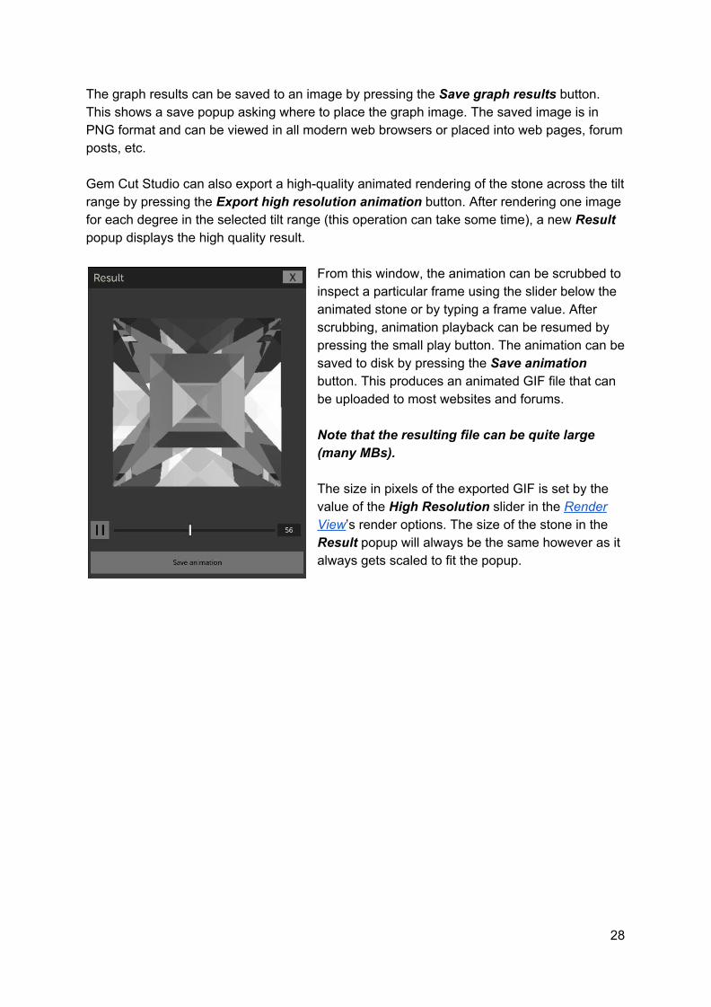
The graph results can be saved to an image by pressing the Save graph results button. This shows a save popup asking where to place the graph image. The saved image is in PNG format and can be viewed in all modern web browsers or placed into web pages, forum posts, etc. Gem Cut Studio can also export a high-quality animated rendering of the stone across the tilt range by pressing the Export high resolution animation button. After rendering one image for each degree in the selected tilt range (this operation can take some time), a new Result popup displays the high quality result.
From this window, the animation can be scrubbed to inspect a particular frame using the slider below the animated stone or by typing a frame value. After scrubbing, animation playback can be resumed by pressing the small play button. The animation can be saved to disk by pressing the Save animation button. This produces an animated GIF file that can be uploaded to most websites and forums. Note that the resulting file can be quite large (many MBs). The size in pixels of the exported GIF is set by the value of the High Resolution slider in the Render View’s render options. The size of the stone in the Result popup will always be the same however as it always gets scaled to fit the popup.
28

Manual Optimizer Selecting this command displays the Manual Optimizer window. This powerful tool quickly runs through multiple combinations of pavilion-crown tangent ratio possibilities and presents the result to the user. No attempt to determine the “best” combination of scaling is made, this subjective task is left to the user.
The main part of the window is a grid of face-up renders captured at various tangent ratios. Pavilion values run along the horizontal axis and crown values run along the vertical axis. The range of tangent ratios for each axis can be set independently by sliders running along the bottom and right side of the grid. The range can also be narrowed down by creating a drag-selection around two or more grid squares. Doing this will automatically update the slider values to correspond to the selected grid range. The number of subdivisions can be adjusted by a slider to show more granular results or fewer higher resolution results. There are also controls to select the lighting model used for the grid renders, as well as the refractive index used to render the gem. By default these will follow the values set in the Render View options. In the top left corner is a preview panel showing the currently selected grid combination. Any grid combination can be selected for preview by clicking on it once. The preview gem can then be spun around to view it from different angles. A small performance graph, similar to the one shown in the Tilt Performance tool offers an overview of light performance for the
29

selected grid combination. On smaller (or wide) screens, this graph is hidden and appears as a tab selector button next to the Preview panel. The tabs then toggle between showing the gem preview and the performance graph. Visible curves in the performance graph follow the ones selected in the Tilt Performance tool. The angle range is also set in the Tilt Performance tool. The Apply button confirms tangent ratio changes selected in the Manual Optimizer tool and Cancel returns to the main interface without change.
Size / Yield Calculator
This tool helps estimate final size and yield of the currently loaded gem design. Various ratios are calculated and displayed on the upper panel. These measurements correspond to the different metrics shown in the cutting instructions printout. In the middle of the popup are 8 editable fields. Changing any of these fields will automatically update the other values, in line with the current gem design. The value shown in the Weight field depends on setting the material’s specific gravity (SG). A drop down provides common materials but any value can be typed in.
30
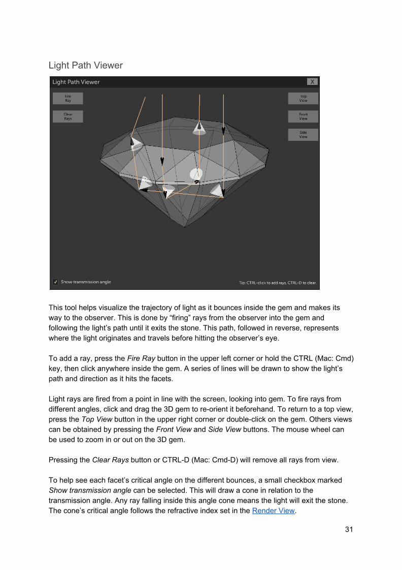
Light Path Viewer
This tool helps visualize the trajectory of light as it bounces inside the gem and makes its way to the observer. This is done by “firing” rays from the observer into the gem and following the light’s path until it exits the stone. This path, followed in reverse, represents where the light originates and travels before hitting the observer’s eye. To add a ray, press the Fire Ray button in the upper left corner or hold the CTRL (Mac: Cmd) key, then click anywhere inside the gem. A series of lines will be drawn to show the light’s path and direction as it hits the facets. Light rays are fired from a point in line with the screen, looking into gem. To fire rays from different angles, click and drag the 3D gem to re-orient it beforehand. To return to a top view, press the Top View button in the upper right corner or double-click on the gem. Others views can be obtained by pressing the Front View and Side View buttons. The mouse wheel can be used to zoom in or out on the 3D gem. Pressing the Clear Rays button or CTRL-D (Mac: Cmd-D) will remove all rays from view. To help see each facet’s critical angle on the different bounces, a small checkbox marked Show transmission angle can be selected. This will draw a cone in relation to the transmission angle. Any ray falling inside this angle cone means the light will exit the stone. The cone’s critical angle follows the refractive index set in the Render View.
31

Cutting Assistant
This tool can be used to proof-cut a design and evaluate tier ordering in relation to meetpoint sequencing or ease of cutting in general. It can also be used as a guide while cutting the design. In the upper left corner is a 3D representation of the design as it progresses in the cutting sequence. The gem can be rotated by clicking and dragging. In the right / top area are labels for the active tier’s name, angle and index. Cutting can be advanced or rewound by using the 6 large buttons. At the bottom is a list of tiers, with the current tier highlighted. Clicking on any tier will advance the cutting sequence to complete this tier. Tiers can be dragged and dropped to change the cutting order. This change will be reflected in the loaded design as well.
32

Design Workflow
Setting up a cut This section will explain how Gem Cut Studio can be set up to cut one or more facets. This will be the basic “building block” for creating new designs. To perform a cut, there are a few variables which need to be set. Note that these can be changed at any time during the cut setup, can be set in any order, and will reflect in real-time on the various views. First, it’s important to choose which side of the gem we want to cut. This is done by pressing either the Pavilion or Crown button at the top in the Mast Controls.
33
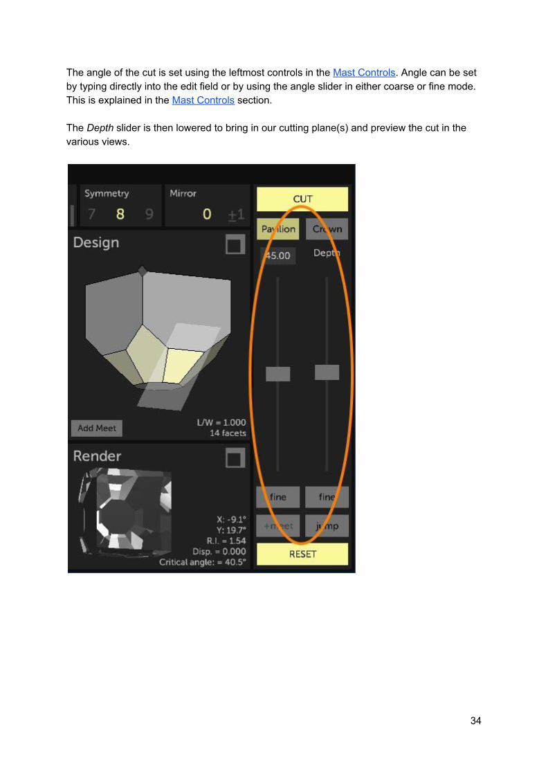
The angle of the cut is set using the leftmost controls in the Mast Controls. Angle can be set by typing directly into the edit field or by using the angle slider in either coarse or fine mode. This is explained in the Mast Controls section. The Depth slider is then lowered to bring in our cutting plane(s) and preview the cut in the various views.
34

To specify the number of facets and how they’re arranged, we use the Index Gear Settings panel at the top of the application. At the center of the Index controls are three rulers. For each of these controls, values can be changed by clicking, then dragging the ruler left or right until the desired value is obtained. Values can also be set directly by first clicking inside the control, then typing in the value using the keyboard (a highlighted frame will confirm the control is active for keyboard input). With the mouse pointer hovering over a ruler, it’s also possible to change its value by scrolling the mouse wheel.
The leftmost of the 3 rulers is the “base index” ruler. In the case of cutting a single facet, this determines the index gear position of the facet. In the case of a simple symmetric set of facets, it determines the index position of the first facet in the series. (or the first basis of mirrored facets if mirroring used, more on that below) The Symmetry ruler determines the number of times our index gear is divided. If there is no mirroring, it also determines the number of facets that will be cut in the tier. The Mirror ruler changes each symmetrical step facet into two facets, equally spaced apart on either side of each symmetric index. The spacing is measured in index increments.
It is much easier to understand these basic concepts by experimenting so the next section contains “follow along” exercises to build up from a basic single cut to a complex, mirrored symmetry.
35

Cutting a basic symmetric tier In this section we will experiment setting up the cut variables in different ways, starting simple and increasing in complexity. It is encouraged to follow along using the application to help understand what’s being explained. Please refer to the previous section to understand the user interface controls being referenced. Make sure to start from a blank design by running File menu… New.
Single Cut Observing a single facet is the best way to understand what’s going on when variables are changed. To begin, let’s bring the interface to a point where we have one facet being cut.
- Set the Symmetry to 1 in the Index Gear Settings. - Make sure Mirror is set to 0. - Make sure the mast angle is set to 45 degrees. - Bring the mast Depth slider down until the cutting plane intersects with the block in
the Design View. (as shown below). Rotate the gem in the Design View to get a more side-on view.
36
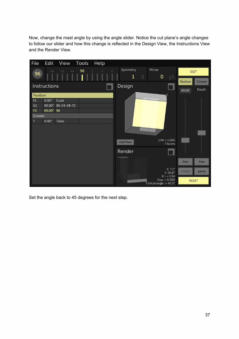
Now, change the mast angle by using the angle slider. Notice the cut plane’s angle changes to follow our slider and how this change is reflected in the Design View, the Instructions View and the Render View.
Set the angle back to 45 degrees for the next step.
37

Change the base index by dragging the base index ruler in the Index Gear Settings. Notice how changing the base index changes the position of our 45 degree cut along the index gear’s axis of rotation.
Set the base index back to 0 (or 96) for the next step
38

Symmetric Cut While single cuts can be used to create a design, it can be tedious, especially when the intended result is to have multiple facets spaced evenly apart on the index gear. For this we use the Symmetry control. Note that symmetry here applies only to the tier being cut, and does not necessarily define the final gem’s symmetry. Using the same 45 degree single cut at base index 0, gradually increase symmetry by dragging the Symmetry ruler. Notice that a symmetry of 2 creates two facets spaced on either side of the index gear’s axis of rotation. A symmetry of 3 creates three facets spaced evenly along the index gear’s axis of rotation, etc. Some numbers on the Symmetry ruler will display as red. This indicates that there is no way to space the resulting facets along whole-numbered index gear values. I.e.: the index gear (96) isn’t divisible by that number (9). In this case, the index values will be rounded to the nearest whole number, resulting in an imperfectly symmetric set of facets.
While Symmetry is set to a value greater than 1, 8 for example, modify the value for base index. Notice that we always have 8 facets but that the set now moves around the index gear’s rotation axis. If the value of the base index is greater than one of the resulting symmetrical facets, it will not be shown as the first index in the instructions. Facets numbers are always ordered in ascending fashion.
39

Mirrored Cut In order to understand this more advanced cutting mode, let’s go back to our single cut setup.
- Set base index to 0 (or 96) - Set Symmetry to 1. - Set mirror to 0. - Set mast angle to 45 degrees - Bring the mast depth down to obtain a cut face on the cube.
Now gradually increase the mirroring amount by dragging the Mirror ruler. Notice that as soon as mirror is set to a non-zero value, the single facet becomes two facets.
The spacing in index values is controlled by the Mirror value. Notice that spacing can be visualized in the base index ruler by showing the active cutting indexes on either side of our chosen base index. Changing the mirror amount changes the index spacing as a function of +/- the mirror value. The facet index values are shown in the Instructions View. It’s important to understand that even though our base index is 96, performing this cut will not result in a facet at 96, but rather at +/- the mirror value from 96. Set Mirror to 2. Now change the base index by dragging the base index ruler. Notice that the reference base index changes and that both mirrored facets follow, maintaining their spacing in relation to the base index.
40

Mirrored Symmetric Cut Let’s re-introduce symmetry, this time with mirroring enabled.
- Set base index to 0 (or 96) - Set Symmetry to 4. - Set Mirror to 2. - Set mast angle to 45 - Bring the mast Depth slider down until the cut forms a point
Notice how there are now 8 facets being cut rather than 4, as would be the case in a basic symmetric cut. It looks more complicated but each facet is the result of our index gear being divided into 4 symmetric parts, starting at the base index, and offset on either side by the mirror amount (+/- 2). Changing the base index now simply offsets all facets. Changing the symmetry results in more or less facets being cut around the index gear’s axis of rotation and changing mirror results in each set of two facets being spaced closer or further apart.
41

Replicating a cut from an existing design It’s possible to find faceting diagrams that include all the information necessary, but are not in a format that can be loaded into Gem Cut Studio. (images or PDFs for example) Replicating these designs in Gem Cut Studio is possible and is a good way to learn about setting up cuts. Each tier needs to be cut independently so let’s look at a few examples of tier setups to see how we can recreate these.
P1 43.12° 12-36-60-84 Cut to point
Angle is easily set, simply type 43.12 into the mast angle edit field. Let’s analyze the index list: There are 4 index values and they are spaced evenly apart (spacing of 24) so we know this is a simple symmetry of 4. Set Symmetry to 4 and Mirror to 0. Because there is no mirroring, we know that the first index is 12 so set the base index to 12. The final step would be to set the correct depth. This can be done by referring to the diagram to choose an intersect (meet) point on the design or by following hints given in the instructions. In this case we would simply bring the Depth slider down until it created a point.
42

A more complicated example would be something like this:
P2 22.00° 10-14-34-38-58-62-82-96 Meet G1
Angle is easily set, simply type 22.00 into the mast angle edit field. (Note that this was from the crown side listing so press the Crown button in the Mast Controls to cut on the correct side.) Let’s analyze the index list: There are 8 index values but they are not spaced evenly apart (spacing between 10-14 is 4 and spacing between 14-34 is 20) so we know this is a mirror setup. Because mirroring doubles the number of index values, we divide the number of index values by 2 to get the symmetry. 8 % 2 = 4. Set Symmetry to 4. Because Mirror is set up using +/- values, we divide our smallest spacing of 4 by 2 to get our mirror value. 4 % 2 = 2. Set Mirror to 2. Because there is mirroring, and the first pair of mirrored indexes is 10-14, we use the center value of 12 as our base index (because 12 +/- 2 gives us 10 and 14). Set base index to 12. The final step would be to set the correct depth. This can be done by referring to the diagram to choose an intersect (meet) point on the design or by following hints given in the instructions. In this case we would bring the facets down to meet the girdle as instructed.
43

When working with mirrored tier setups, there are always two possible solutions that would give the correct result. Going back to the example above, we had 10-14-34-38-58-62-82-96 And found that one solution was to cut a symmetry of 4, mirror of +/- 2 starting at index 12. If we now consider the larger spacing, which we calculated to be between 14 and 34 (so 20), we could also set up a valid cut using symmetry of 4 but now with a mirror of +/- 10 around a central index of 24. (24 +/- 10 also gives us 14 and 34) Both are valid and Gem Cut Studio will accept both setups to create the same cut. However, when editing an existing tier, Gem Cut Studio may use a different solution to set up the cut for editing.
When making multiple cuts at the same angle and the same depth (oval culet tips for example), Gem Cut Studio will combine the cuts into a single tier line with multiple facets, as these can be correctly cut on the faceting machine without changes to angle or depth. In the case of trying to replicate these setups (or Edit them), it may be that it is impossible to do so with the simple Symmetry mode tools offered. In this case the index gear mode can be changed to “Arbitrary” and values typed in directly using the “-” (minus) character to separate indexes.
44

Adding meetpoints A meetpoint in Gem Cut Studio is a design tool which allows the user to ensure the cutting plane intersects exactly with a given three-dimensional point while setting up a cut. This is the equivalent of a traditional meet point in faceting, with the additional functionality of locking certain controls in the cut setup to ensure this point is always intersected. There are two ways to add meetpoints in the application: The first is through the Jump button in the Mast controls. (The Jump functionality is explained there). After each jump, the +meet button will highlight. If the +meet button is pressed at this point, a meetpoint lock will be added at the intersection of the cutting plane and the gem before the jump (the point that was highlighted prior to the jump) The second way is by using the Add Meet button at the bottom of the Design View. When this button is pressed, text is displayed in the Design View inviting the user to select either a point of intersection of existing facets (meet) or an edge. Moving the mouse cursor over each possible point or edge brings it into focus by highlighting it, and clicking confirms selection of what’s highlighted. The Design View can still be rotated and zoomed at this stage to narrow in on a section of the gem. If the selection is an edge, a popup will be shown to aid with setting up the meetpoint along the edge.
45

While the Select Edge Meetpoint popup is visible, a small dot is drawn on the selected edge in the background. Note: the popup can be moved out of the way by dragging its upper border. A slider and edit field provide a way to move the meetpoint along the edge with precision, or the ratio can be set using the predefined ratio buttons at the top. Pressing the Add button confirms the selection and adds the edge point as a meet. After a meetpoint is added, the cutting plane will attempt to always intersect the chosen meetpoint(s), regardless of how the base index or mast angle is changed. Please note that the meetpoint(s) are in relation to the primary cutting plane in a symmetrical set-up. I.e.: the cutting plane that corresponds to the base index. This is the cutting plane that is shown as a semi-transparent 3D rectangle when adjusting the cut. This can be confusing if viewing the design from the opposite side for example. In the case where mirror offsets are used, the primary cutting plane is the lighter of the two cutting planes shown. When one meetpoint is locked in, the base index and mast angle values can still be adjusted but mast depth will be locked out. If two meetpoints are set, then only the base index can be changed. In this case the angle will be locked out as the conditions to satisfy arbitrary angles would result in fractional base index values and therefore not allowed. When adding a second meetpoint, the effect of the cut setup will be temporarily hidden in order to help locate the desired point or edge. After the second meetpoint is confirmed, both meetpoints’ effect will be shown.
46

Examples
Cutting the Standard Round Brilliant - Step by step This example will build upon the User Interface reference and the concepts explained in the Design Workflow section to cut a 16-sided standard round brilliant (SRB) from scratch in Gem Cut Studio. To start, make sure the application is reset by going into File menu … New. Let’s start cutting our pavilion break facets (Pavilion should already be the active side in the Mast Controls, but select it if it’s not)
- Set the base index to 3 and symmetry to 16 in the Index Gear Settings. - Set the cutting angle to 43 in the Mast Controls. (Typing directly into the edit field
works best if we know the angle we want.) - Bring the cutting depth slider down until the cut forms a point. (It’s better to go a bit
deeper to avoid leaving a tiny culet facet) - Press CUT
47

Now we will cut the girdle.
- Change the cutting angle to 90 - Bring the cutting depth slider down until a set of girdle facets is shown all around the
gem (exact depth isn’t important but it is important to cut past the original cube side facets)
- Press CUT
48

For the pavilion mains, we will use the “jump” function and experiment with locking a meetpoint.
- Set the base index to 0 (or 96) and the symmetry to 8. - Set the cutting angle to 41. - Press the Jump button in the Mast Controls. This will bring the cutting plane in line
with the culet tip. Note that this won’t actually show any cut any facets, because we’re only touching the tip of the gem.
- Press the Jump button again and the cutting plane should jump to a point intersecting the girdle as shown:
Now before actually cutting the break facets, let’s experiment with basic meetpoint locking. You’ll notice that after jumping to an intersection point, the “+meet” button at the bottom of the Mast Controls becomes highlighted.
- Press the +meet button. Notice the mast Depth slider is no longer shown. - Move the mast angle slider and notice that the cutting plane swivels around a
highlighted point on the gem. This is our locked meetpoint. - Set the cutting angle to 41 degrees to return to our desired value. - Press CUT.
49

We will now cut the crown “break” facets. While it’s actually faster to cut this first crown tier “by eye” and adjust it later, let’s take this opportunity to try adding a meetpoint manually.
- Press the Crown button in the Mast Controls. - Set the base index to 3 and the symmetry to 16. - Set the mast angle to 32. - In the Design View, press the Add Meet button.
Notice the design shows the cutting plane and the next jump meetpoint as a little diamond at the top of our gem. (Rotate the design if necessary)
- Move the mouse cursor over the edge that has the jump meetpoint. It’s important to use an edge that coincides with our base index (in line with the cutting plane and the suggested jump meetpoint). Otherwise, setting the meetpoint will cut too far and will give unintended results.
50

- Click anywhere on the edge. That will bring up the Select Edge Meetpoint popup. If necessary, move the popup out of the way by dragging its title bar in order to see the Design view and the meetpoint we’re defining. (small yellow diamond on the edge)
- Set the value to something that looks acceptable, about 0.95. It’s not necessary to be too precise here because we can always adjust the girdle size later using Edit menu… Resize Girdle
- Press the Add button to close the popup. This will set the mast depth to intersect with our meetpoint.
- Press CUT
51

Next up are the crown mains or “kite” facets.
- Set the base index to 0 (or 96) and the symmetry to 8. - Set the mast angle to 28. - Press the Jump button twice or until the cutting plane reaches the top of the girdle
and defines our facets. - Press CUT
52

Now for the “star” facets.
- Set the base index to 6. - Set the mast angle to 13. - Press the Jump button twice to bring the depth down to the intersection of the crown
breaks and kite facets. - Press CUT.
53

And finally for the table.
- Set the mast angle to 0. When the angle is zero, base index and symmetry are ignored so there’s no reason to change these to 0 and 1 for example.
- Press the Jump button twice to bring the cutting plane down to the intersection of the star and kite facets.
- Press CUT and you’re done.
At this point, we can adjust the girdle thickness more precisely using the Edit menu’s Resize Girdle command to bring it to a certain percentage of our gem width for example.
54

Optimizing an existing design for a different material A common use case for gem design software is to evaluate and remap an existing design to a material different than what the design’s author intended. While it would be tempting to simply provide a tool which remaps angles to the new refractive index (RI) via tangent ratio, there is no way to ensure that the result is ideal. In some cases a design intended for a low RI can be cut as-is in higher RI materials and will perform just fine. In some cases, changing the angles to match the new RI will give optimal results. In the case of porting a high RI design to match a low RI material, there might simply not be a ratio of angles that performs acceptably. Therefore, it is best to trust your eyes in this case. With that in mind, there are two ways this task can be completed in Gem Cut Studio:
First method: Simple tangent ratio 1 - Open the original design. 2 - Expand the Render View and set the Refractive index to the target value. 3 - Open the Edit menu and select Scale (Tangent ratio). 4 - Play with the two sliders in the Mast Controls while keeping an eye on the raytraced result in the Render View until an acceptable result is found. 5 - Press APPLY in the Mast Controls then Save or Print the design.
Second method: Manual Optimizer 1 - Open the original design. 2 - Expand the Render View and set the Refractive index to the target value. 3 - Open the Tools menu and select Manual Optimizer. 4 - Select a set of angle ratios that looks acceptable using the preview thumbnails in the grid. 5 - Press the Apply button then Save or Print the design. Note that RI can also be changed in the Manual Optimizer but this won’t change the value used in the Render View upon exiting or in the printout.
55

Tips and Tricks
Running out of material and “growing the gem” Under certain circumstances, it’s possible to cut the stone in a way that there is not enough material left to keep cutting the rest of the design. This can happen for example when cutting the girdle to match the outline of the starting cube instead of leaving enough room for the crown. (Remember that designs are always rescaled so it’s better to leave more material than needed)
In this case, rather than starting over or going back to re-cut the girdle deeper, it’s possible to simply re-grow the rough. Select the top of the gem (the “table” facet) by clicking on it in the Design View or by selecting the “table” row in the Instructions View. Then at the bottom of the Instructions View, press the Edit Tier button and bring the mast Depth slider up. This will extend the table facet to a certain point. Make sure to set the depth at a point where the application still offers to cut the facet, then press CUT. Another option is simply to delete the table facet, which will force Gem Cut Studio to recut the design in the original starting cube. This usually results in a new, higher table facet.
56
Advanced topics This section contains information about topics which are considered outside the normal scope of using the application and are presented as a way for the user to expand the functionality of the application or for experimenting. Any changes made through the methods mentioned here should be considered at the user’s own risk and may be undone without notice by future versions of Gem Cut Studio.
Adding and modifying materials The list of gem materials shown in the Render View are contained in an text-based XML file located in the application’s root documents folder and named “materials.xml”. New materials can be added manually using any text or XML editor by adding lines with appropriate data and formatting. Existing material values can be modified, and list order can be changed by rearranging lines within the XML structure. New materials can also be added directly through the application by first setting up the material as usual through the Render View parameters. Then if the CTRL (or Cmd) key is held pressed, a small disk icon will appear next to the dropdown list of materials. Clicking this icon offers to name and save the material. Note that this process is blind and pays no attention to double entries, ordering, etc. Re-ordering and cleanup can be performed using the manual editing procedures outlined above.
Adding lighting models The list of lighting models shown in the Render View is built using the files in the “LightingModels” folder, located in the application’s root documents folder. Images placed in this directory will be loaded on startup and added to the list of available lighting models throughout the application, provided they are in the correct format. The correct format for lighting models is: PNG image format, 256x256 pixels, 8-bit per channel RGB Pixel values in the image will be used by the raytracer to determine the lighting environment. Color images can be used but care should be taken as they will appear to alter the gem color. Colorless images should however still use all three color channels, as single-channel grayscale PNGs are not supported. Also note that the lightmap look-up is done using spherical coordinates, which means that only the pixel values within a centered circle are
57

ever used, and any real-world images should be pre-warped to a sphere map if realism is the goal. Color intensity values should be pre-scaled to a maximum brightness value of 128 (in a 0-255 range) for normal lighting, where a value of 128 (mid gray) is considered pure white if used across all channels. Values above 128 are used for simulated high dynamic range light sources and can be used to create flashes in the gem. (see the random.png for an example of this) Note that lighting models should not include head shadow, as this is calculated as a post-process based on user-selectable parameters.
The .GCS file format Gem Cut Studio’s native format is a simple XML-based hierarchical structure representing the data needed to re-create the gem design. The rough structure of the file is as follows: GemCutStudio header -- index gear information -- tier block ---- facet block ------ point in the facet ------ [more points] ---- [more facets] -- [more tiers] -- render block -- info block Here is the listing for an example GCS file which includes most common features and describes which fields are required vs optional: <!-- Required header to identify a GCS file, version is checked to be less than or equal to app version-->
<GemCutStudio version="1000">
<!-- index block: gear should be obvious. Base, symmetry and mirror are optional and represent the current state of the UI in the app. -->
<!-- These are NOT the values for symmetry/mirror as would be printed in a faceting diagram. Those need to be calculated from the data.-->
<index gear="96" base="0" symmetry="4" mirror="0"/>
<!-- tier blocks, one for each tier. "angle" is required(degrees). 0.0 is table, 90 is girdle (always included in pav) and anything over 90 is pavilion. 180 is the max and would be a flat culet-->
<!-- depth is not required as it can be calculated from the facet vertices (below). However, if you don't
include facet edge verts, depth is required-->
<!-- all other attributes are optional-->
<tier angle="137.00000000000003" depth="0.67470026016235329" name="P1" instructions="Cut to point"
visible="true" guide="false" frosting="0">
58

<!-- facet block, one for each facet in the tier. nx, ny, nz are the normal perpendicular to the facet, pointing out. The normal is not required because it can be worked out from the tier angle and index_angle
if supplied-->
<!-- index_angle represents the index gear value in absolute degrees, rather than increments of the
wheel used. Note that winding order is a function of the tier angle (pav vs crown has opposite index
ordering)-->
<facet nx="-0" ny="-0.68199836006249825" nz="-0.73135370161917068" index_angle="0">
<!-- vertex block, one for each point making up the facet edge. Note that while this makes the file load faster and assist visualization tools, it isn't required because it can be calculated from the tier
and facet data-->
<!-- negative X is front (index 0), Y is side and positive Z is up. Vertex winding order is not
important and will be sanitized based on the normal-->
<vertex x="1.1102230246251565e-016" y="1.1102230246251565e-016" z="-0.63505441789868788"/>
<vertex x="-0.99999999999999989" y="-1.0000000000000002" z="0.29746066823897344"/>
<vertex x="1" y="-1" z="0.29746066823897299"/>
</facet>
<facet nx="-0.68199836006249825" ny="-4.1760355433714127e-017" nz="-0.73135370161917068"
index_angle="90">
<vertex x="1.1102230246251565e-016" y="1.1102230246251565e-016" z="-0.63505441789868788"/>
<vertex x="-1" y="1" z="0.29746066823897299"/>
<vertex x="-0.99999999999999989" y="-1.0000000000000002" z="0.29746066823897344"/>
</facet>
<facet nx="-8.3520710867428254e-017" ny="0.68199836006249825" nz="-0.73135370161917068"
index_angle="180">
<vertex x="1" y="1" z="0.29746066823897277"/>
<vertex x="-1" y="1" z="0.29746066823897299"/>
<vertex x="1.1102230246251565e-016" y="1.1102230246251565e-016" z="-0.63505441789868788"/>
</facet>
<facet nx="0.68199836006249825" ny="1.2528106630114239e-016" nz="-0.73135370161917068"
index_angle="270">
<vertex x="1" y="1" z="0.29746066823897277"/>
<vertex x="1.1102230246251565e-016" y="1.1102230246251565e-016" z="-0.63505441789868788"/>
<vertex x="1" y="-1" z="0.29746066823897299"/>
</facet>
</tier>
<tier angle="90" depth="1" name="G1" instructions="Level girdle" visible="true" guide="false"
frosting="0">
<facet nx="0" ny="1" nz="0" index_angle="0">
<vertex x="-1" y="1" z="0.35978420577996117"/>
<vertex x="-1" y="1" z="0.29746066823897299"/>
<vertex x="1" y="1" z="0.29746066823897277"/>
<vertex x="1" y="1" z="0.35978420577996101"/>
</facet>
<facet nx="1" ny="6.123233995736766e-017" nz="0" index_angle="90">
<vertex x="1" y="1" z="0.35978420577996101"/>
<vertex x="1" y="1" z="0.29746066823897277"/>
<vertex x="1" y="-1" z="0.29746066823897299"/>
<vertex x="1" y="-1" z="0.35978420577996112"/>
</facet>
<facet nx="1.2246467991473532e-016" ny="-1" nz="0" index_angle="180">
<vertex x="-0.99999999999999989" y="-1.0000000000000002" z="0.3597842057799609"/>
<vertex x="1" y="-1" z="0.35978420577996112"/>
<vertex x="1" y="-1" z="0.29746066823897299"/>
<vertex x="-0.99999999999999989" y="-1.0000000000000002" z="0.29746066823897344"/>
</facet>
<facet nx="-1" ny="-1.8369701987210297e-016" nz="0" index_angle="270">
<vertex x="-0.99999999999999989" y="-1.0000000000000002" z="0.3597842057799609"/>
<vertex x="-0.99999999999999989" y="-1.0000000000000002" z="0.29746066823897344"/>
<vertex x="-1" y="1" z="0.29746066823897299"/>
<vertex x="-1" y="1" z="0.35978420577996117"/>
</facet>
</tier>
<tier angle="32" depth="0.57782161235809326" name="C1" instructions="Set girdle width" visible="true"
guide="false" frosting="0">
<facet nx="-0" ny="-0.5299192642332049" nz="0.84804809615642596" index_angle="0">
<vertex x="0.55947557472994758" y="-0.55947557472994758" z="0.63505441789868766"/>
<vertex x="1" y="-1" z="0.35978420577996112"/>
<vertex x="-0.99999999999999989" y="-1.0000000000000002" z="0.3597842057799609"/>
<vertex x="-0.55947557472994736" y="-0.55947557472994758" z="0.63505441789868766"/>
</facet>
59

<facet nx="0.5299192642332049" ny="-3.2448196537485745e-017" nz="0.84804809615642596" index_angle="90">
<vertex x="0.55947557472994736" y="0.55947557472994736" z="0.63505441789868777"/>
<vertex x="1" y="1" z="0.35978420577996101"/>
<vertex x="1" y="-1" z="0.35978420577996112"/>
<vertex x="0.55947557472994758" y="-0.55947557472994758" z="0.63505441789868766"/>
</facet>
<facet nx="6.489639307497149e-017" ny="0.5299192642332049" nz="0.84804809615642596" index_angle="180">
<vertex x="-0.55947557472994736" y="0.55947557472994736" z="0.63505441789868788"/>
<vertex x="-1" y="1" z="0.35978420577996117"/>
<vertex x="1" y="1" z="0.35978420577996101"/>
<vertex x="0.55947557472994736" y="0.55947557472994736" z="0.63505441789868777"/>
</facet>
<facet nx="-0.5299192642332049" ny="9.7344589612457222e-017" nz="0.84804809615642596"
index_angle="270">
<vertex x="-0.55947557472994736" y="0.55947557472994736" z="0.63505441789868788"/>
<vertex x="-0.55947557472994736" y="-0.55947557472994758" z="0.63505441789868766"/>
<vertex x="-0.99999999999999989" y="-1.0000000000000002" z="0.3597842057799609"/>
<vertex x="-1" y="1" z="0.35978420577996117"/>
</facet>
</tier>
<tier angle="7.0167092985348768e-015" depth="0.46025484800338745" name="T" instructions="" visible="true"
guide="false" frosting="0">
<facet nx="-0" ny="-1.2246467991473532e-016" nz="1" index_angle="0">
<vertex x="0.55947557472994758" y="-0.55947557472994758" z="0.63505441789868766"/>
<vertex x="-0.55947557472994736" y="-0.55947557472994758" z="0.63505441789868766"/>
<vertex x="-0.55947557472994736" y="0.55947557472994736" z="0.63505441789868788"/>
<vertex x="0.55947557472994736" y="0.55947557472994736" z="0.63505441789868777"/>
</facet>
</tier>
<!-- rendering parameters. Most of these should be obvious. lighting model is ignored right now as users can supply their own.-->
<render refractive_index="1.54" dispersion="0" clarity="100" density="1" lighting_model="Random">
<!-- default stone color in RGB where 0.0 is no color and 1.0 is full color for each channel--> <color r="1" g="1" b="1"/>
<!-- other colors (pleochroism) will be added here in the future--> </render>
<info title="Example" author="Rej Poirier" date="Nov 7 2017" header2="Test of my XML spec" ri_min="1.4"
ri_max="1.8099999" size_min="5" size_max="15" shape="Square" footer1="This is a only a test." footer2="If
this were a real gem design, it would be more complex."/>
</GemCutStudio>
60