Geberit Sovent ES
36
Geberit Sovent The innovative soil and waste drainage system
Transcript of Geberit Sovent ES
Geberit SoventThe innovative soil and waste drainage system

Contents
1
Introduction ..................................................................... 3The Sovent history ............................................................................................ 3
Know-How Installed .......................................................................................... 3
Who to ask in case of questions? ..................................................................... 3
Standards and approvals ................................................ 4Years of operation in the correct places ............................................................ 4
Standards and approvals .................................................................................. 4
Fields of application ........................................................ 5Where Sovent is best used ............................................................................... 5
For how many storeys is Sovent best used? ..................................................... 5
Feature and benefits ....................................................... 6Why is Sovent a better solution? ....................................................................... 6
Better performance ........................................................................................... 6
Cheaper than a conventional solution ............................................................... 6
One dimension for all ........................................................................................ 6
No maintenance required .................................................................................. 6
Service life like other fittings .............................................................................. 6
Function ........................................................................... 7How does a system with Sovent work? ............................................................ 7
Function of the opening to the stack ................................................................. 8
Maximum velocity of fall .................................................................................... 8
Planning ........................................................................... 9Which points have to be observed? .................................................................. 9
Connection load per floor .................................................................................. 9
Total connection load ....................................................................................... 9
Is it necessary to have a Sovent fitting on every floor? ..................................... 10
Segmentation into zones ................................................................................ 10
Determination of the waste water figures ........................................................ 11
Connection of the branch ventilation ............................................................... 11
Insertion of the first floor .................................................................................. 12
End of the Sovent stack .................................................................................. 12
Joining of stack pipes ..................................................................................... 12
Vertical to horizontal transition of the stack ..................................................... 13
Contents
2
Offset line of the stack .................................................................................... 14
Mixed installations ........................................................................................... 14
Drainage line dimension .................................................................................. 15
Joining of ventilation pipes .............................................................................. 15
Sovent stack with air admittance valve ............................................................ 15
Is a deareator necessary? ............................................................................... 15
Acoustic considerations .................................................................................. 16
Calculation ..................................................................... 17Hydraulic calculation basis .............................................................................. 17
How is a Geberit Sovent system calculated? .................................................. 17
Simultaneous use of appliances ...................................................................... 17
Calculation example 1 ..................................................................................... 18
Calculation example 2 ..................................................................................... 18
Calculation of a collector pipe ......................................................................... 19
Installation ..................................................................... 20Installation ...................................................................................................... 20
Material requirement ....................................................................................... 20
Connection to a Sovent fitting ......................................................................... 20
Typical prefabrication ...................................................................................... 21
Reference buildings ...................................................... 22Hotel Gran Bali, Benidorm, Spain .................................................................... 22
Casino Towers, Brisbane, Australia ................................................................. 22
Twin Towers, Zurich, Switzerland .................................................................... 23
Bosmal City, Sarajevo, Bosnia ........................................................................ 23
Hyatt Regency Hotel, Montréal, Canada ......................................................... 24
Arabella Sheraton Hotel, Cape Town, South Africa ......................................... 24
Annex ............................................................................. 25Dimension table .............................................................................................. 25
Drain factor ..................................................................................................... 25
Recommended discharge pipe ....................................................................... 26
Collector pipe ................................................................................................. 27
Practical application design 1 Single stack with Sovent fitting (prewall) ............ 28
Practical application design 2 Single stack with Sovent fitting (under ceiling) ... 29
Introduction
3
1 IntroductionThe Sovent history Sovent, a single stack drainage system, was developed in 1959 by Fritz Sommer,
a renowned vocational school director in Bern, Switzerland. The aim of the
development was to substantially increase the performance of a soil and waste
drainage system, and thus to eliminate a separate vent stack and reduce the
diameter of the stacks in high-rise buildings. The specially designed branch inlet
fitting, which is covered by worldwide patents, reduces the pneumatic pressure
fluctuations in stacks preventing the syphonage of traps.
To prove the virtues of the Sovent system, a 10-storey hydraulic test tower was
built in Bern, Switzerland. During the sixties and seventies, the system was
furthermore thoroughly tested in multi-storey privately and governmentally owned
test installations set up in New York, Tokyo, Paris and Stockholm, and has
received wide design code recognition.
This versatile drainage system with the engineered design offers an economical
and high-performance alternative to conventional drainage systems.
Know-How Installed Since Geberit's founding in 1874, the name has been synonymous with quality,
ease of installation and technical knowledge.
This is no accident. By applying our knowledge to find ways to make
improvements, Geberit creates innovations that optimize synergy and
performance throughout the entire system. The result is fast- and easy-to-install,
highly reliable, integrated systems that set the standard for the sanitary industry.
Who to ask in case of questions? Our sales force, technical advisors and service personnel will be pleased to offer
support and answer any of your questions.
Please contact your local market organisation for further information or get in
touch with Geberit at www.geberit.com.
Standards and approvals
4
2 Standards and approvalsYears of operation in the correct
places
Over the last four decades, this innovative system has been installed in thousands
of high-rise apartment, office and hotel buildings all over the world.
Standards and approvals Since Sovent is a special fitting it has not yet found entry in every national
standard.
Nevertheless, Sovent is mentioned in several important national standards like
DIN EN 12056-2.
All pipes and connections to a Geberit Sovent system are regulated in local
standards. This means the system has to be installed in accordance with these
regulations.
For the stack itself and the base of the stack Geberit gives technical parameters to
follow. These are described in detail in this manual.
Fields of application
5
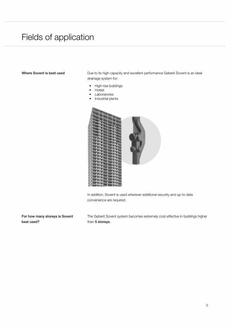
3 Fields of applicationWhere Sovent is best used Due to its high capacity and excellent performance Geberit Sovent is an ideal
drainage system for:
• High-rise buildings• Hotels• Laboratories• Industrial plants
In addition, Sovent is used wherever additional security and up-to-date
convenience are required.
For how many storeys is Sovent
best used?
The Geberit Sovent system becomes extremely cost-effective in buildings higher
than 5 storeys.

Feature and benefits
6
4 Feature and benefitsWhy is Sovent a better solution? There is a simple answer to that:
• Better performance for less money
Better performance In comparison with conventional systems, Geberit Sovent:
• Reduces the pneumatic and hydraulic pressure• Offers versatile branch joining possibilities• Reduces stack sizes with the same loading capacities as a secondary
ventilated system• Saves space
Cheaper than a conventional
solution
With regard to costs, Geberit Sovent has even more advantages:
• It simplifies the design of domestic waste water stacks• It offers 6 connections on one multiple branch fitting• Saves material and installation time• No separate ventilation pipes or back vents are required
One dimension for all The fitting is characterized by the most common stack size of 110 mm in
diameter, and could reach a capacity of up to over 70 apartments per stack.
No maintenance required As with any other system using Geberit high-density polyethylene (HDPE) pipes
and fittings, no maintenance is required.
Service life like other fittings As the Geberit Sovent fitting is also made of high-density polyethylene, it has the
same service life as other fittings.
Function
7
5 FunctionHydraulic and pneumatic balancing of a stack system is a very complex matter.
Each stack design has its own characteristics. The capacity of the stack and vent
system is influenced by the flow rate of the appliances, their simultaneous
discharge pattern, and the branch inlet configuration and building drain design. To
secure the water seal in the traps, the positive and negative pressures in a
drainage system have to be limited.
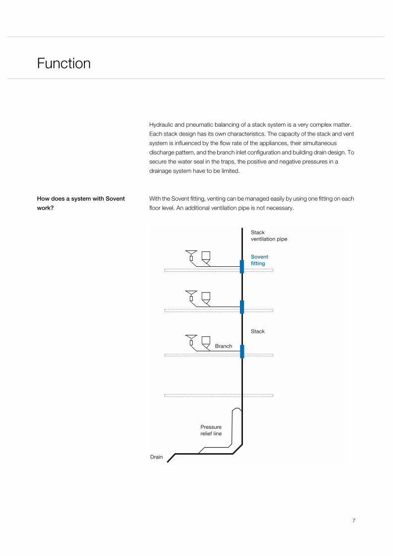
How does a system with Sovent
work?
With the Sovent fitting, venting can be managed easily by using one fitting on each
floor level. An additional ventilation pipe is not necessary.
Pressure relief line
Drain
Stack
Branch
Stackventilation pipe
Soventfitting
Function
8
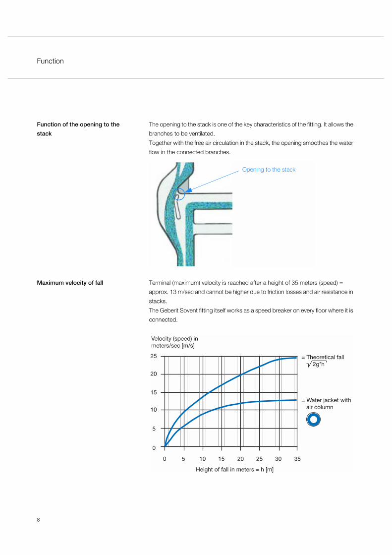
Function of the opening to the
stack
The opening to the stack is one of the key characteristics of the fitting. It allows the
branches to be ventilated.
Together with the free air circulation in the stack, the opening smoothes the water
flow in the connected branches.
Maximum velocity of fall Terminal (maximum) velocity is reached after a height of 35 meters (speed) =
approx. 13 m/sec and cannot be higher due to friction losses and air resistance in
stacks.
The Geberit Sovent fitting itself works as a speed breaker on every floor where it is
connected.
0
5
50
Height of fall in meters = h [m]
= Water jacket with air column
Velocity (speed) inmeters/sec [m/s]
10 15 20 25 30 35
10
15
20
25 = Theoretical fall 2g*h
Opening to the stack

Planning
9
6 PlanningWhich points have to be
observed?
When a Geberit Sovent system is planned, the following points have to be
observed in addition to the general rules for waste and drainage stack design:
• Use of a Sovent fitting instead of a common branch fitting• Pressure relief ventilation at the base of the stack• Every stack has to be ventilated through the roof with the same diameter (110 mm)
Connection load per floor The branches have to be designed in accordance with the local regulations (e.g.
EN 12056-2, see 'Annex'), which include the dimensioning diameter and the
maximum length of the branch. It is permitted to use all connection possibilities
simultaneously. A maximum of 8 WC‘s may be connected to a Sovent fitting.
Total connection load As stated in the calculation chapter, the maximum simultaneous flow per Sovent
stack is 8.7 l/s.
This corresponds to approximately 73 standard type apartments (with a total
number of DU’s of 4.1, see calculation example on page 18).
Stack design according toSoventregulations
Branch design according to local regulations

Planning
10
Is it necessary to have a Sovent
fitting on every floor?
As a rule, there is a Sovent fitting on every floor. The maximum distance between
two fittings shall not exceed 6 m.
Segmentation into zones If the building design requires more than one stack or the maximum load
connected to a Sovent stack exceeds 8.7 l/s (DU > 303), segmentation is
required. The total load has to be distributed to different Sovent stacks.
max 6 m
to end of Sovent stack
Zone A
Stack 1 Stack 2
Zone B

Planning
11
Determination of the waste water
figures
One of the first steps when planning a Geberit Sovent system is to determine the
amount of waste water.
For this, all DU’s of the appliances have to be taken into account and included in
the equation for the Geberit Sovent system (see chapter 'Calculation').
Connection of the branch
ventilation
The maximum length of a collector branch pipe without ventilation is determined
by local regulations.
If a ventilation pipe is necessary according to these regulations, the pipe is
connected to the Sovent stack.
Sovent stack
Soventfitting
Branch design according to localregulations
Branch ventilation according to local regulations
Stack design according to Soventregulations
45˚

Planning
12
Insertion of the first floor Sometimes appliances must be connected which are rather close to the base of
the stack, for example on the first floor. They are connected to the pressure relief
line at the base of the stack (either above A or below B of a floor).
End of the Sovent stack At the base of the stack, the pressure relief line eliminates any pressure build-up,
that might occur.
Joining of stack pipes If Sovent stacks are joined together, the resulting drainage pipe is calculated as a
collector pipe (see chapter 'Calculation').
2 m
2 m
AFirstfloor
2 m
2 m
B
End of Sovent system
Pressure relief line atbase of Sovent stack
ø 110 mm
Planning
13
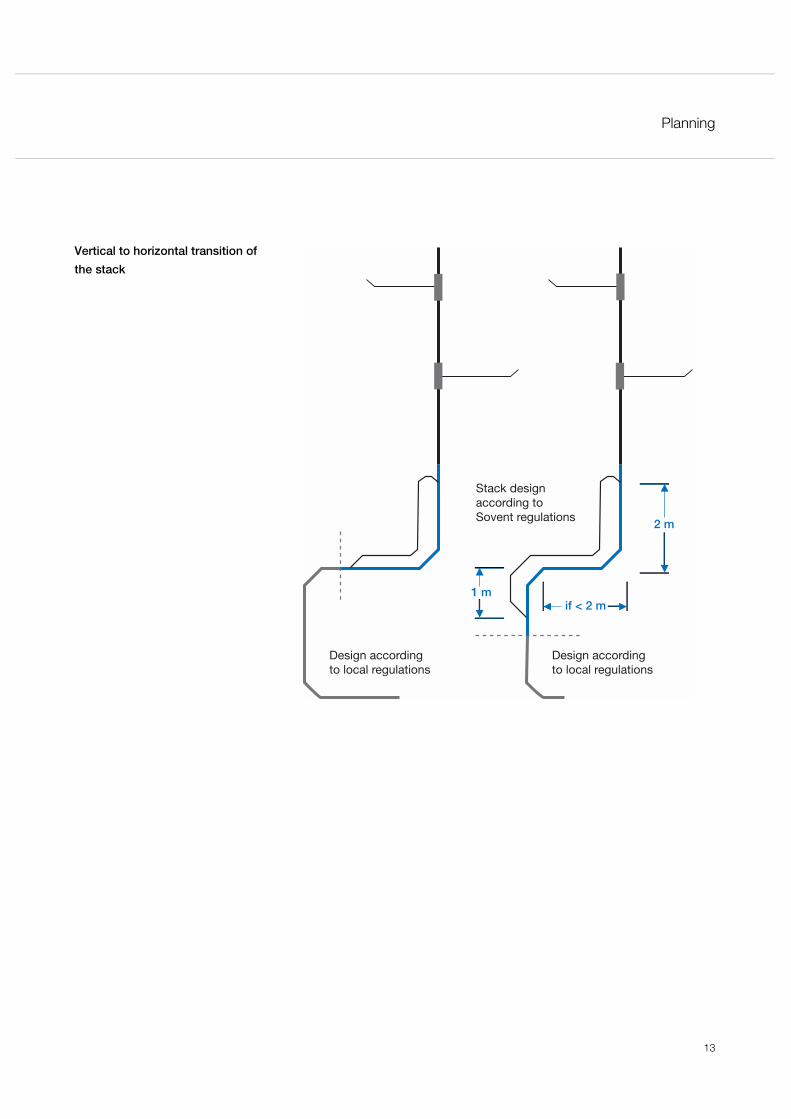
Vertical to horizontal transition of
the stack
Design according to local regulations
Design according to local regulations
Stack design according to Sovent regulations
if < 2 m1 m
2 m
Planning
14
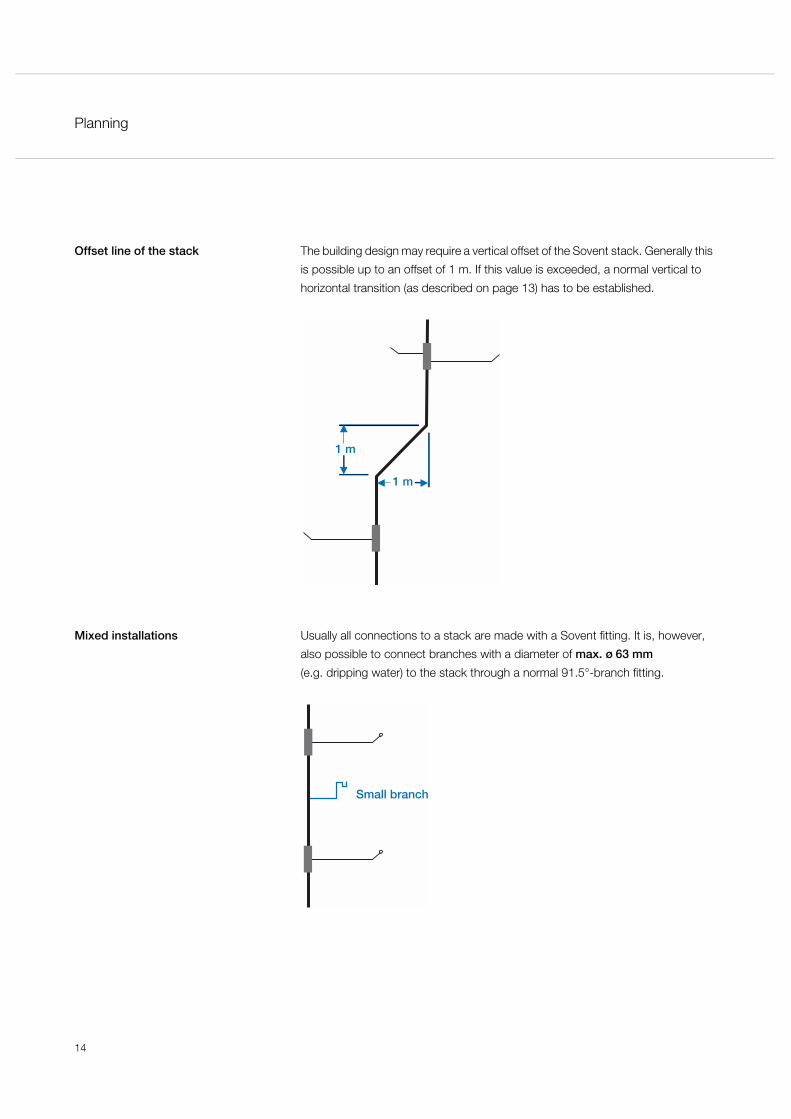
Offset line of the stack The building design may require a vertical offset of the Sovent stack. Generally this
is possible up to an offset of 1 m. If this value is exceeded, a normal vertical to
horizontal transition (as described on page 13) has to be established.
Mixed installations Usually all connections to a stack are made with a Sovent fitting. It is, however,
also possible to connect branches with a diameter of max. ø 63 mm
(e.g. dripping water) to the stack through a normal 91.5°-branch fitting.
1 m
1 m
Small branch
Planning
15
Drainage line dimension Dimensioning of the drainage line also follows local standards and regulations.
See the section 'Calculation of a collector pipe' in the chapter 'Calculation' for
information on how to evaluate a total drainage load.
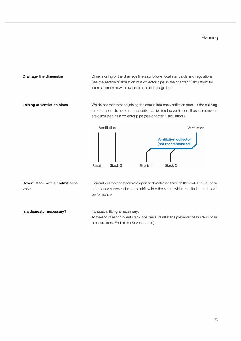
Joining of ventilation pipes We do not recommend joining the stacks into one ventilation stack. If the building
structure permits no other possibility than joining the ventilation, these dimensions
are calculated as a collector pipe (see chapter 'Calculation').
Sovent stack with air admittance
valve
Generally all Sovent stacks are open and ventilated through the roof. The use of air
admittance valves reduces the airflow into the stack, which results in a reduced
performance.
Is a deareator necessary? No special fitting is necessary.
At the end of each Sovent stack, the pressure relief line prevents the build-up of air
pressure (see 'End of the Sovent stack').
Stack 1 Stack 2
Ventilation
Stack 1 Stack 2
Ventilation
Ventilation collector(not recommended)
Planning
16
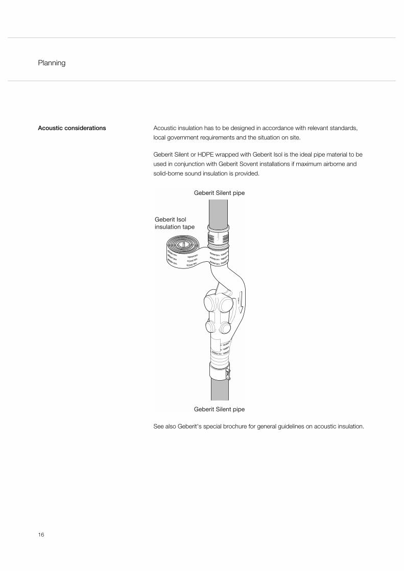
Acoustic considerations Acoustic insulation has to be designed in accordance with relevant standards,
local government requirements and the situation on site.
Geberit Silent or HDPE wrapped with Geberit Isol is the ideal pipe material to be
used in conjunction with Geberit Sovent installations if maximum airborne and
solid-borne sound insulation is provided.
See also Geberit's special brochure for general guidelines on acoustic insulation.
Geberit Silent pipe
Geberit Silent pipe
Geberit Isol insulation tape
Calculation
17
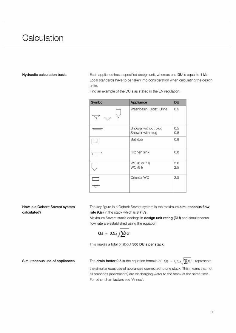
7 CalculationHydraulic calculation basis Each appliance has a specified design unit, whereas one DU is equal to 1 l/s.
Local standards have to be taken into consideration when calculating the design
units.
Find an example of the DU’s as stated in the EN regulation:
How is a Geberit Sovent system
calculated?
The key figure in a Geberit Sovent system is the maximum simultaneous flow
rate (Qs) in the stack which is 8.7 l/s.
Maximum Sovent stack loadings in design unit rating (DU) and simultaneous
flow rate are established using the equation:
This makes a total of about 300 DU’s per stack.
Simultaneous use of appliances The drain factor 0.5 in the equation formula of represents
the simultaneous use of appliances connected to one stack. This means that not
all branches (apartments) are discharging water to the stack at the same time.
For other drain factors see 'Annex'.
Symbol Appliance DU
Washbasin, Bidet, Urinal 0.5
Shower without plugShower with plug
0.50.8
Bathtub 0.8
Kitchen sink 0.8
WC (6 or 7 l)WC (9 l)
2.02.5
Oriental WC 2.5
Qs 0.5x DU∑=
Qs 0.5x DU∑=
Calculation
18
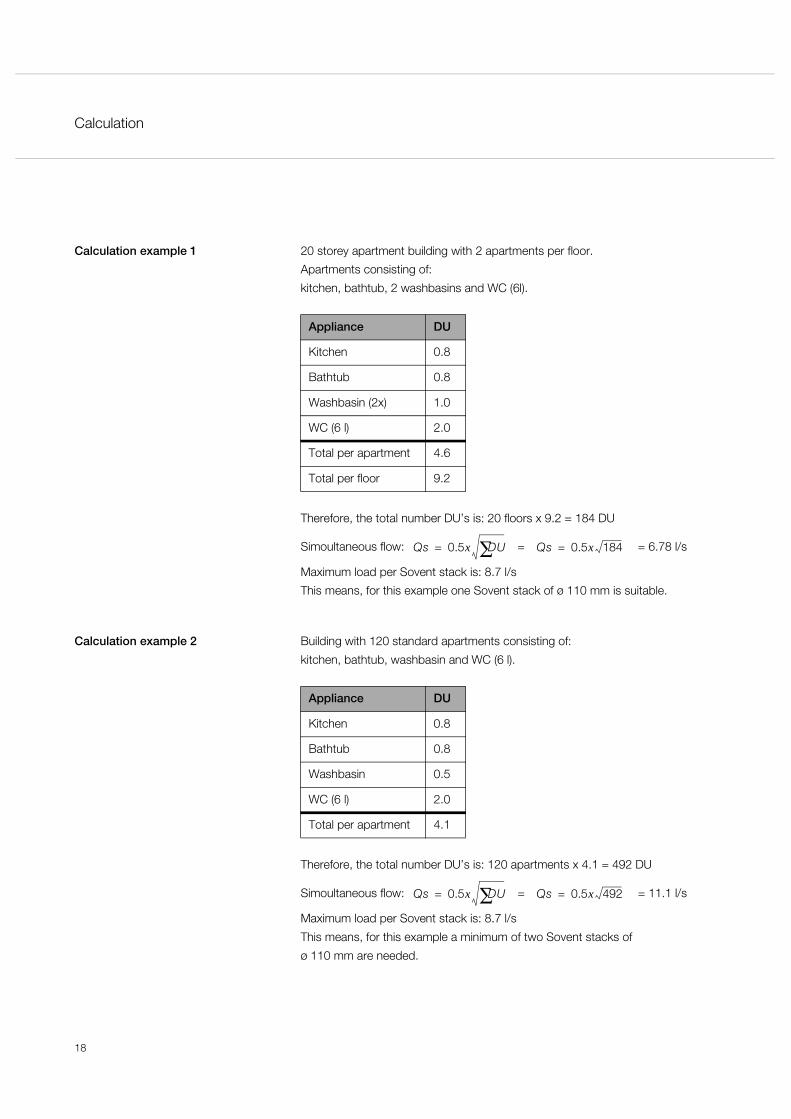
Calculation example 1 20 storey apartment building with 2 apartments per floor.
Apartments consisting of:
kitchen, bathtub, 2 washbasins and WC (6l).
Therefore, the total number DU’s is: 20 floors x 9.2 = 184 DU
Simoultaneous flow: = = 6.78 l/s
Maximum load per Sovent stack is: 8.7 l/s
This means, for this example one Sovent stack of ø 110 mm is suitable.
Calculation example 2 Building with 120 standard apartments consisting of:
kitchen, bathtub, washbasin and WC (6 l).
Therefore, the total number DU’s is: 120 apartments x 4.1 = 492 DU
Simoultaneous flow: = = 11.1 l/s
Maximum load per Sovent stack is: 8.7 l/s
This means, for this example a minimum of two Sovent stacks of
ø 110 mm are needed.
Appliance DU
Kitchen 0.8
Bathtub 0.8
Washbasin (2x) 1.0
WC (6 l) 2.0
Total per apartment 4.6
Total per floor 9.2
Qs 0.5x DU∑= Qs 0.5x 184=
Appliance DU
Kitchen 0.8
Bathtub 0.8
Washbasin 0.5
WC (6 l) 2.0
Total per apartment 4.1
Qs 0.5x DU∑= Qs 0.5x 492=

Calculation
19
Calculation of a collector pipe A high-rise building is usually equipped with several stacks, which are then
combined into a collector pipe. The dimension of this pipe is calculated in the
following way:
According to the dimension table of the EN regulation (see 'Annex'), the resulting
collector pipe has a dimension of DN ø = 150 mm (Geberit OD = 160 mm).
Point 1: = 6.7 l/s
Point 2: = 9.1 l/s
Point 3: = 10.5 l/s
SoventStack Aø = 110 mm
SoventStack Bø = 110 mm
SoventStack Cø = 110 mm
ΣDUA
(e.g. 180)ΣDUB
(e.g. 150)ΣDUC
(e.g. 110)
1 2 3
Collector pipeø = ?
Slope 2%
0.5x DUA∑ 0.5x 180=
0.5x DUA∑ DU
B∑+ 0.5x 330=
0.5x DUA∑ DU
B∑ DUC∑+ + 0.5x 440=
Installation
20
8 InstallationInstallation In general, the installation of a Geberit Sovent system follows the same rules as
the installation of conventional drainage systems. It does, however, require much
less work since secondary ventilation is not necessary. The installation of a Sovent
fitting is similar to the installation of an ordinary branch fitting.
The process can therefore be called simple, easy and quick.
Material requirement
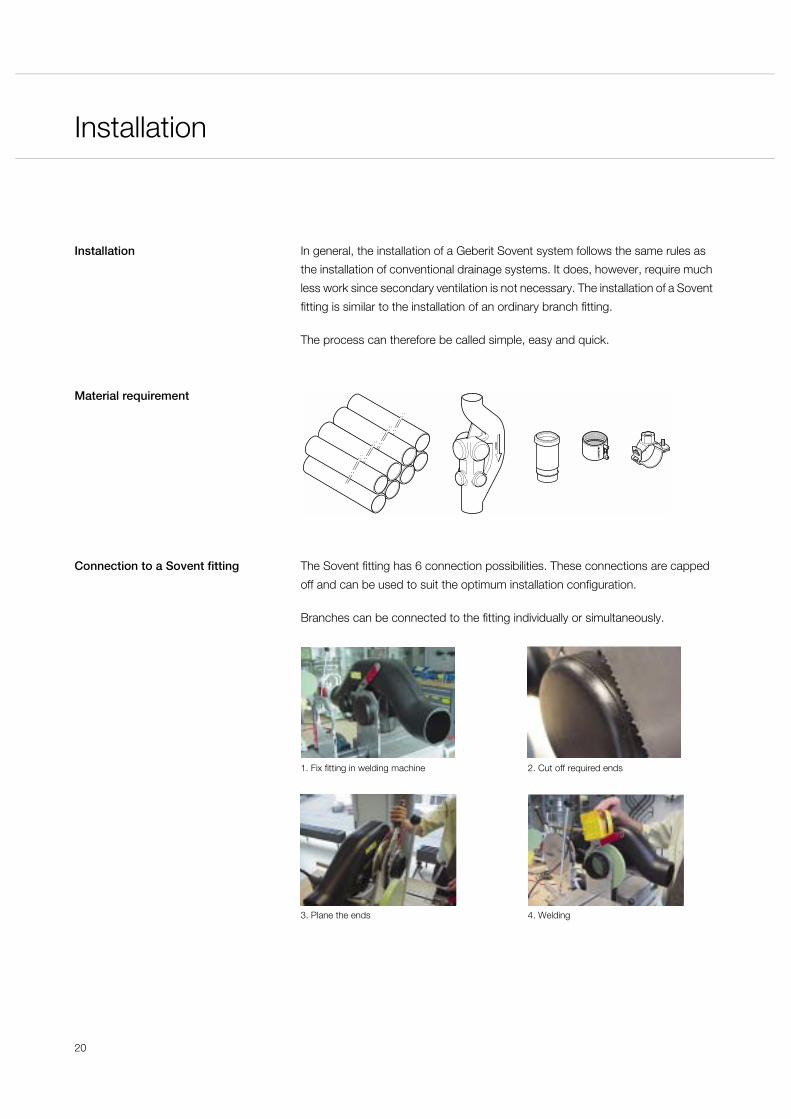
Connection to a Sovent fitting The Sovent fitting has 6 connection possibilities. These connections are capped
off and can be used to suit the optimum installation configuration.
Branches can be connected to the fitting individually or simultaneously.
1. Fix fitting in welding machine 2. Cut off required ends
3. Plane the ends 4. Welding
Installation
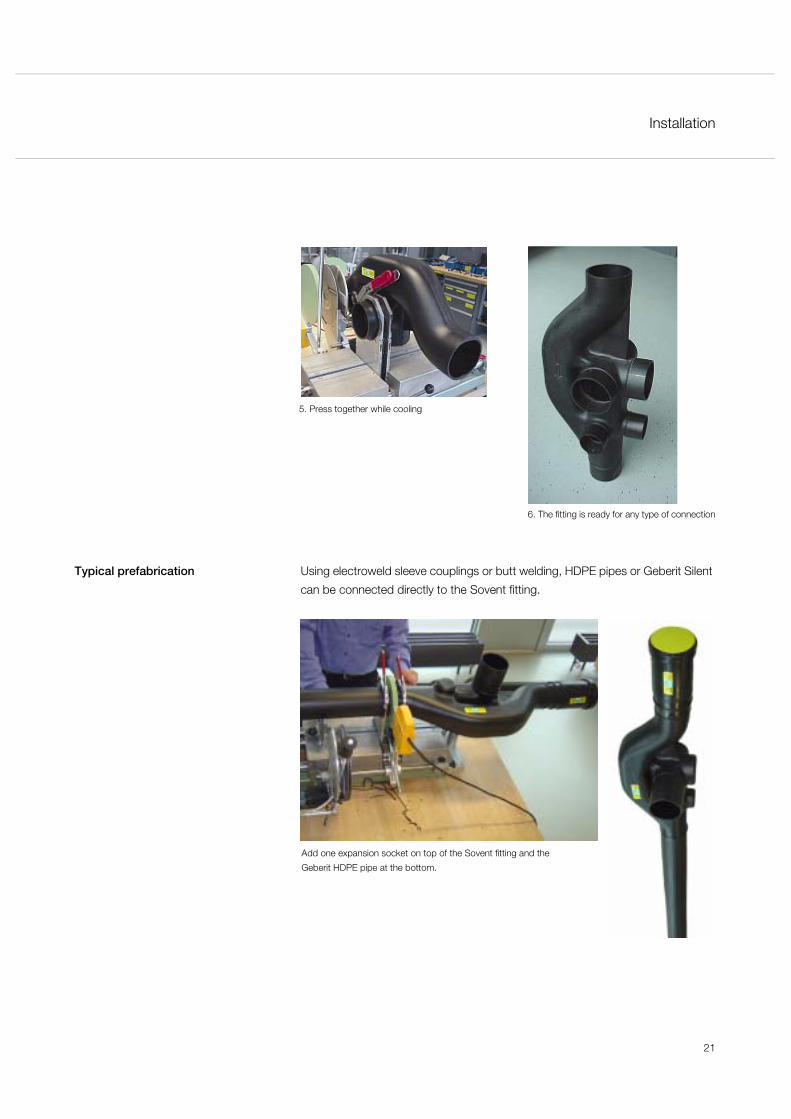
21
6. The fitting is ready for any type of connection
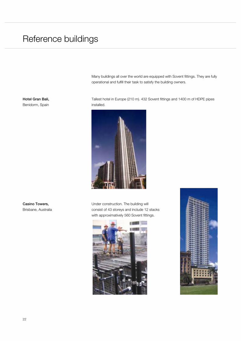
Typical prefabrication Using electroweld sleeve couplings or butt welding, HDPE pipes or Geberit Silent
can be connected directly to the Sovent fitting.
Add one expansion socket on top of the Sovent fitting and the
Geberit HDPE pipe at the bottom.
5. Press together while cooling
Reference buildings
22
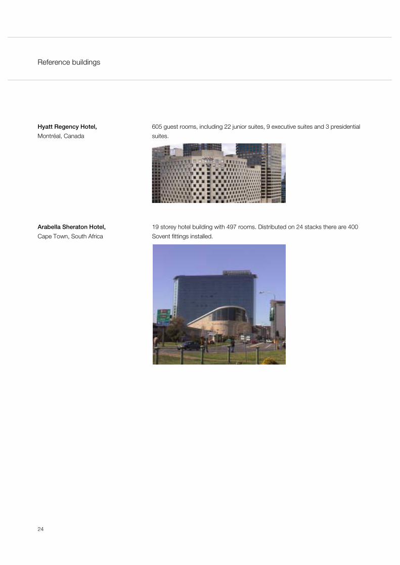
9 Reference buildingsMany buildings all over the world are equipped with Sovent fittings. They are fully
operational and fulfill their task to satisfy the building owners.
Hotel Gran Bali,
Benidorm, Spain
Tallest hotel in Europe (210 m). 432 Sovent fittings and 1400 m of HDPE pipes
installed.
Casino Towers,
Brisbane, Australia
Under construction. The building will
consist of 43 storeys and include 12 stacks
with approximatively 560 Sovent fittings.

Reference buildings
23
Twin Towers,
Zurich, Switzerland
Business building.
Bosmal City,
Sarajevo, Bosnia
Under construction. Apartment buildings with over 20 storeys. 520 Sovent fittings
installed.
Reference buildings
24
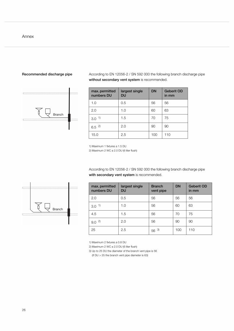
Hyatt Regency Hotel,
Montréal, Canada
605 guest rooms, including 22 junior suites, 9 executive suites and 3 presidential
suites.
Arabella Sheraton Hotel,
Cape Town, South Africa
19 storey hotel building with 497 rooms. Distributed on 24 stacks there are 400
Sovent fittings installed.

Annex
25
10 AnnexDimension table EN 12056-2 / SN 592 000 Maximum expected discharge for Sovent stack.
Reading example: or Calculation using the formula:
20 apartments with a DU of 5 20 apartments with a DU of 5
= 100 DU’s = 100 DU’s
See dimension table = 5 l/s Formula: Qs = 0.5 x = 5 l/s
The maximum expected discharge for the above stack is 5 l/s.
Drain factor EN 12056-2 / SN 592 000 recommends the following drain factors (K).
Sum of all connected DUs
Rel
evan
t sim
ulta
neou
s flo
w r
ate
in l/
s
100
Typical drain factor of a building type K
Irregular use: e.g. residential buildings, guest houses, offices 0.5
Regular use: e.g. hospital, schools, restaurants, hotels 0.7
Frequent use: e.g. public toilets, shower rooms 1.0
Special use: e.g. laboratories 1.2
Annex
26
Recommended discharge pipe According to EN 12056-2 / SN 592 000 the following branch discharge pipe
without secondary vent system is recommended.
1) Maximum 1 fixtures a 1.5 DU
2) Maximum 2 WC a 2.0 DU (6 liter flush)
According to EN 12056-2 / SN 592 000 the following branch discharge pipe
with secondary vent system is recommended.
1) Maximum 2 fixtures a 0.8 DU
2) Maximum 2 WC a 2.0 DU (6 liter flush)
3) Up to 25 DU the diameter of the branch vent pipe is 56
(If DU > 25 the branch vent pipe diameter is 63)
max. permitted numbers DU
largest single DU
DN Geberit OD in mm
1.0 0.5 56 56
2.0 1.0 60 63
3.0 1) 1.5 70 75
6.5 2) 2.0 90 90
15.0 2.5 100 110
max. permitted numbers DU
largest single DU
Branch vent pipe
DN Geberit OD in mm
2.0 0.5 56 56 56
3.0 1) 1.0 56 60 63
4.5 1.5 56 70 75
9.0 2) 2.0 56 90 90
25 2.5 56 3) 100 110
Branch
Branch
Annex
27
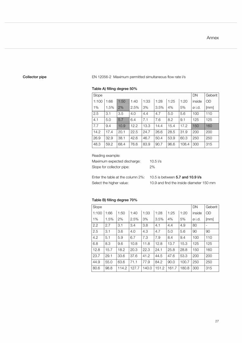
Collector pipe EN 12056-2 Maximum permitted simultaneous flow rate l/s
Reading example:
Maximum expected discharge: 10.5 l/s
Slope for collector pipe: 2%
Enter the table at the column 2%: 10.5 is between 5.7 and 10.9 l/s
Select the higher value: 10.9 and find the inside diameter 150 mm
Table A) filling degree 50%
Slope DN Geberit
1:100 1:66 1:50 1:40 1:33 1:28 1:25 1:20 inside OD
1% 1.5% 2% 2.5% 3% 3.5% 4% 5% ø i.d. [mm]
2.5 3.1 3.5 4.0 4.4 4.7 5.0 5.6 100 110
4.1 5.0 5.7 6.4 7.1 7.6 8.2 9.1 125 125
7.7 9.4 10.9 12.2 13.3 14.4 15.4 17.2 150 160
14.2 17.4 20.1 22.5 24.7 26.6 28.5 31.9 200 200
26.9 32.9 38.1 42.6 46.7 50.4 53.9 60.3 250 250
48.3 59.2 68.4 76.6 83.9 90.7 96.6 108.4 300 315
Table B) filling degree 70%
Slope DN Geberit
1:100 1:66 1:50 1:40 1:33 1:28 1:25 1:20 inside OD
1% 1.5% 2% 2.5% 3% 3.5% 4% 5% ø i.d. [mm]
2.2 2.7 3.1 3.4 3.8 4.1 4.4 4.9 80 -
2.5 3.1 3.6 4.0 4.3 4.7 5.0 5.6 90 90
4.2 5.1 5.9 6.7 7.3 7.9 8.4 9.4 100 110
6.8 8.3 9.6 10.8 11.8 12.8 13.7 15.3 125 125
12.8 15.7 18.2 20.3 22.3 24.1 25.8 28.8 150 160
23.7 29.1 33.6 37.6 41.2 44.5 47.6 53.3 200 200
44.9 55.0 63.6 71.1 77.9 84.2 90.0 100.7 250 250
80.6 98.8 114.2 127.7 140.0 151.2 161.7 180.8 300 315
Annex
28
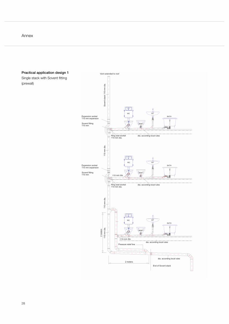
Practical application design 1
Single stack with Sovent fitting
(prewall)
Vent extended to roof
BIDET
BATH
WTWC
WC
BIDET
WT
BATH
BATH
WT
BIDET
WC
110 mm expansionExpansion socket
Sovent fitting110 mm
Sov
ent s
tack
110
mm
dia
.11
0 m
m d
ia.
110
mm
dia
.11
0 m
m d
ia.
2 m
eter
s
2 meters
Pressure relief line
End of Sovent stack
dia. according local rules
110 mmSovent fitting
110 mm expansion
110 mm dia.Ring seal socket dia. according local rules
Expansion socket
dia. according local rules
110 mm dia.
110 mm dia.
dia. according local rules110 mm dia.Ring seal socket

Annex
29
Practical application design 2
Single stack with Sovent fitting
(under ceiling)
Vent extended to roof
BATH
WT
BIDET
GRATING
110 mm dia.
110 mm expansionExpansion socket
Sovent fitting110 mm
Ring seal socket110 mm dia.
dia. according local rules
Sov
ent s
tack
110
mm
dia
.11
0 m
m d
ia.
110
mm
dia
.11
0 m
m d
ia.
2 m
eter
s
2 meters
Pressure relief line
End of Sovent stack
dia. according local rules
110 mmSovent fitting
110 mm expansion
110 mm dia.Ring seal socket dia. according local rules
Expansion socket
dia. according local rules
110 mm dia.
110 mm dia.
BIDET
WT
GRATING
BATH
GRATING
BIDET
WT
BATH
WC
WC
WC
Annex
30
Index
31
AAcoustic insulation ................................ 16
Additional ventilation pipe ....................... 7
Advantages ............................................ 6
Air admittance valves ............................ 15
Air resistance .......................................... 8Apartments
standard type..................................... 9Appliance ............................................. 17
connection ...................................... 12
BBase of the stack ................................. 12
Better performance ................................ 6
Branch joining ........................................ 6
Butt welding ......................................... 21
CCollector pipe ................................ 15, 19
dimension ....................................... 19Common stack size ................................ 6
Connection possibilities ........................ 20
Connections ........................................... 6
Contact .................................................. 3
Cost-effective ......................................... 5
DDesign unit rating .................................. 17Dimension
table ............................................... 19Discharge pattern ................................... 7Drainage
load ................................................ 15pipe ................................................ 12
Dripping water ...................................... 14
EEase of installation .................................. 3
Electroweld sleeve couplings ................ 21
FFirst floor .............................................. 12
Free air circulation .................................. 8
Friction losses ......................................... 8
GGeberit
Isol .................................................. 16Silent ....................................... 16, 21
General rules .......................................... 9
HHDPE pipes .......................................... 21
High-rise apartment ................................ 4
High-rise buildings .................................. 5
Hotel building ......................................... 4
Hotels ..................................................... 5
Hydraulic balancing ................................ 7
Hydraulic test tower ................................ 3
IIndustrial plants ...................................... 5
Innovative system ................................... 4
Isol ....................................................... 16
KKey characteristics ................................. 8
Key figure ............................................. 17
Know-How Installed ............................... 3
LLaboratories ........................................... 5
Local standards ...................................... 4
MMarket organisation ................................ 3Maximum
distance .......................................... 10simultaneous flow ............................. 9
Multiple branch fitting .............................. 6
32
NNational standards ................................. 4
OOffice building ......................................... 4
Opening to the stack .............................. 8
PPatents ................................................... 3
Pneumatic balancing .............................. 7
Polyethylene ........................................... 6
prefabrication ....................................... 21Pressure
build-up .......................................... 12hydraulic ........................................... 6pneumatic ......................................... 6
Pressure relief ventilation ........................ 9
SSales force ............................................. 3
Segmentation ....................................... 10
Separate vent stack ................................ 3Service
life ..................................................... 6personnel .......................................... 3
Silent .................................................... 16Simultaneous flow
maximum .......................................... 9rate ................................................. 17
Simultaneous use of appliances ............ 17
Single stack drainage system ................. 3
Sound insulation ................................... 16
Sovent history ........................................ 3
Special fitting ................................... 4, 15
Speed breaker ........................................ 8Stack
loadings .......................................... 17vertical offset .................................. 14
Standard type apartments ...................... 9Standards
local .................................................. 4national ............................................. 4
Syphonage ............................................. 3
TTechnical
advisors ............................................ 3knowledge ........................................ 3
VVelocity ................................................... 8Ventilation
pipe ................................................ 11stack ............................................... 15
Versatile drainage system ....................... 3
Vertical offset ........................................ 14
WWaste
drainage ........................................... 3water .............................................. 11water stacks ..................................... 6
Water flow .............................................. 8
Worldwide patents .................................. 3
ZZones ................................................... 10

Geberit International Sales AG
CH-8640 Rapperswil
Switzerland
www.geberit.com Sub
ject
to c
hang
e w
ithou
t not
ice.
The
info
rmat
ion
in th
is d
ocum
ent c
onta
ins
gene
ral d
escr
iptio
n of
the
tech
nica
l opt
ions
ava
ilabl
e, w
hich
do
not a
lway
s ha
ve to
be
pres
ent i
n th
e in
divi
dual
cas
es.
The
requ
ired
feat
ures
sho
uld
ther
efor
e be
spe
cifie
d in
eac
h in
divi
dual
cas
e at
the
time
of c
losi
ng th
e co
ntra
ct.
D40
01-0
01&
BD
E ©
11-
2004