gears gear train torque - open.edu · 4.3 Simple gear trains On many occasions, the motor that will...
6
7–3 2 The purpose of these notes The format of this activity is somewhat different from the others. The challenges are not described in this Handbook but will bepresented to you at the Residential School on a series of Challenge Sheets. The notes in this Handbook contain background information and resources that will provide you with a theoretical understanding of the practicalprinciples that you will be applying in Robotics Activity and that will help you complete the challenges. At the Residential School itself you will have an opportunity to complete severalhands-on exercises that illustrate the principles described in the background resource information. The notes also include several short exercises for you to check your understanding of the material. Y ou are strongly encouraged to read through these notes before attending the Residential School. 3 The challenge-based approach Throughout this activity , you will be set several challenges. For example, one challenge might be to program your robot todrive between various checkmarks placed on the ground, or to use a light sensor to track a moving infrared light source. The tasks are defined as challenges for various reasons: • theremay be several ways of achieving a solution to the task, rather than a single best approach; • it may be possible to refine any particular solution and improveits performance against some measure(such as time taken to complete the task, or precision achieved while completing the task). Challenges implicitly incorporate some performance measure that you can use to rate the effectiveness of your solution, such as the time taken for the robot to complete a task, or the accuracy with whichit does so. Thereis thus a mildly competitive element to the activity – both against oneself (trying to improve the quality of one’ s own solution) and against other groups. Thereis little point simply copying someone else’ s workespecially if you don’t refine it – your solution is unlikely to be better than theirs and you may not fully understand how it was arrived at. 4 Mechanical considerations One of the most important mechanical components is a gear wheel. A gear wheel is a wheel with teeth that can mesh or engage with the teeth of another gear wheel. When gears are meshed together , we say wehave a gear train (Figure 1). Gears can be used to change the speed or direction of a turning motion,as well as the amount of turning force, or torque, that is available. When two gears are meshed together properly , turning one gear will turn the other in the opposite direction. Y ou probably also noticed from Figure1 that with the correct arrangement gears can be used to rotate shafts that are at right angles toeachother . Furthermore, the number of times the second gear turns relative to the first is determined by the number of teeth on each gear , in particular on the ratio of the number of teeth on one gear to the number of teeth on the other .
Transcript of gears gear train torque - open.edu · 4.3 Simple gear trains On many occasions, the motor that will...
7–3
2 The purpose of these notesThe format of this activity is somewhat different from the others. The challengesare not described in this Handbook but will be presented to you at the ResidentialSchool on a series of Challenge Sheets. The notes in this Handbook containbackground information and resources that will provide you with a theoreticalunderstanding of the practical principles that you will be applying in RoboticsActivity and that will help you complete the challenges.At the Residential Schoolitself you will have an opportunity to complete several hands-on exercises thatillustrate the principles described in the background resource information.
The notes also include several short exercises for you to check your understandingof the material. You are strongly encouraged to read through these notes beforeattending the Residential School.
3 The challenge-based approachThroughout this activity, you will be set several challenges. For example, onechallenge might be to program your robot to drive between various checkmarksplaced on the ground, or to use a light sensor to track a moving infrared lightsource.
The tasks are defined as challenges for various reasons:
• there may be several ways of achieving a solution to the task, rather than asingle best approach;
• it may be possible to refine any particular solution and improve its performanceagainst some measure (such as time taken to complete the task, or precisionachieved while completing the task).
Challenges implicitly incorporate some performance measure that you can useto rate the effectiveness of your solution, such as the time taken for the robot tocomplete a task, or the accuracy with which it does so.
There is thus a mildly competitive element to the activity – both against oneself(trying to improve the quality of one’s own solution) and against other groups.There is little point simply copying someone else’s work especially if you don’trefine it – your solution is unlikely to be better than theirs and you may not fullyunderstand how it was arrived at.
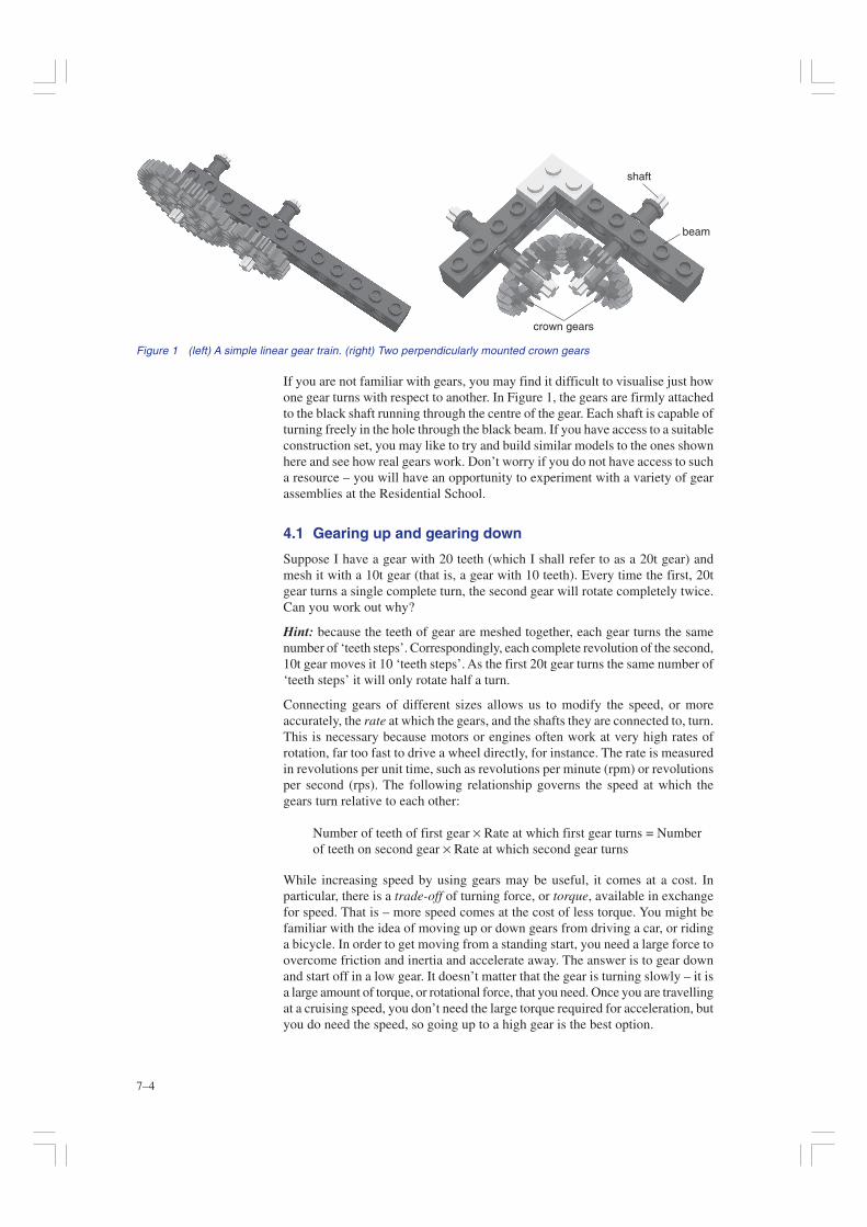
4 Mechanical considerationsOne of the most important mechanical components is a gear wheel. A gearwheel is a wheel with teeth that can mesh or engage with the teeth of anothergear wheel. When gears are meshed together, we say we have a gear train(Figure 1).
Gears can be used to change the speed or direction of a turning motion, as wellas the amount of turning force, or torque, that is available.
When two gears are meshed together properly, turning one gear will turn theother in the opposite direction. You probably also noticed from Figure 1 thatwith the correct arrangement gears can be used to rotate shafts that are at rightangles to each other. Furthermore, the number of times the second gear turnsrelative to the first is determined by the number of teeth on each gear, in particularon the ratio of the number of teeth on one gear to the number of teeth on theother.
7–4
If you are not familiar with gears, you may find it difficult to visualise just howone gear turns with respect to another. In Figure 1, the gears are firmly attachedto the black shaft running through the centre of the gear. Each shaft is capable ofturning freely in the hole through the black beam. If you have access to a suitableconstruction set, you may like to try and build similar models to the ones shownhere and see how real gears work. Don’t worry if you do not have access to sucha resource – you will have an opportunity to experiment with a variety of gearassemblies at the Residential School.
4.1 Gearing up and gearing down
Suppose I have a gear with 20 teeth (which I shall refer to as a 20t gear) andmesh it with a 10t gear (that is, a gear with 10 teeth). Every time the first, 20tgear turns a single complete turn, the second gear will rotate completely twice.Can you work out why?
Hint: because the teeth of gear are meshed together, each gear turns the samenumber of ‘teeth steps’. Correspondingly, each complete revolution of the second,10t gear moves it 10 ‘teeth steps’. As the first 20t gear turns the same number of‘teeth steps’ it will only rotate half a turn.
Connecting gears of different sizes allows us to modify the speed, or moreaccurately, the rate at which the gears, and the shafts they are connected to, turn.This is necessary because motors or engines often work at very high rates ofrotation, far too fast to drive a wheel directly, for instance. The rate is measuredin revolutions per unit time, such as revolutions per minute (rpm) or revolutionsper second (rps). The following relationship governs the speed at which thegears turn relative to each other:
Number of teeth of first gear × Rate at which first gear turns = Numberof teeth on second gear × Rate at which second gear turns
While increasing speed by using gears may be useful, it comes at a cost. Inparticular, there is a trade-off of turning force, or torque, available in exchangefor speed. That is – more speed comes at the cost of less torque. You might befamiliar with the idea of moving up or down gears from driving a car, or ridinga bicycle. In order to get moving from a standing start, you need a large force toovercome friction and inertia and accelerate away. The answer is to gear downand start off in a low gear. It doesn’t matter that the gear is turning slowly – it isa large amount of torque, or rotational force, that you need. Once you are travellingat a cruising speed, you don’t need the large torque required for acceleration, butyou do need the speed, so going up to a high gear is the best option.
Figure 1 (left) A simple linear gear train. (right) Two perpendicularly mounted crown gears
shaft
beam
crown gears
7–5
Using gears also introduces friction into the system at the points where the teethmesh. Overcoming these frictional forces requires energy, which would otherwisebe available to the output gear.
When talking about gear trains, we say that we are gearing up when a large geardrives a smaller one, and gearing down when a small gear drives a larger one. Inthe first case, of gearing up, the second, smaller gear rotates faster than the firstgear but delivers less force. In the second case, gearing down, the second, largergear rotates more slowly than the first but can deliver larger torque.
4.2 Gear ratios
When gears are connected together, it is common to talk about the correspondinggear ratio. The ratio of one gear to another is usually given in terms of the ratioof the number of teeth on the first gear to the number of teeth on the second.Conventionally, the ratio is written in the order: driver gear: follower gear.
That is, the motor (or pedals, on a bike) turns the shaft that the driver gear isattached to. Gears that are meshed with a driver gear are driven by it. The followergear is the gear at the other end of the gear train to the driver gear. It is convenientto write down a gear ratio in the following way:
Number of teeth on first, driver gear : Number of teeth on second, drivengear
So for example, the ratio of a 20t gear connected to a 10t gear is written as 20:10(which reads as ‘20 to 10’).
Ratios can be simplified in a similar way to how we simplify fractions, by dividingthrough each side of the ratio by the same number. So for example, we wouldcommonly write the fraction 10/20 as , by dividing through both the numerator(the top bit, i.e. 10) and the denominator (that is, the bottom bit – 20 in this case)by 10. Similarly, dividing 5/15 through by 5 gives us the fraction 1/3. In the caseof our 20:10 ratio, this means we can divide through by 10 and simplify it to theratio 2:1.
����
��
� ���
��
� ����������
�
In a similar way, the ratio of a 12t gear driving a 48t gear is a ratio of 1:4, sincewe can divide through both sides of the original 12:48 ratio by 12.
You can also use this resemblance between ratios and fractions to help you identifywhether you are gearing up into a high gear, or gearing down into a low gear.For example, if you regard the gear ratio 1:4 as the fraction 1/4, you canimmediately see that this is less than 1. Hence, you are gearing down and usinga low gear.
In contrast, viewing the ratio 10:1 as the fraction 10/1 (that is, 10), this is greaterthan 1 and hence you are gearing up into a high gear where the driven gear isrotating faster than the driver gear.
The gear ratio expresses in a straightforward way the relative torque (or turningforce) and speed of the gears too, so a 2:1 (gearing up) ratio tells you that thesecond gear will deliver twice the speed but half the torque of the first. A 1:4(gearing down) ratio tells you that the second gear will deliver four times theforce of the first but will rotate at a quarter of the speed.
7–6
Hence, it is possible to also describe the gear ratio as:
Rate at which second gear turns : Rate at which first gear turns
or
Torque of first gear: Torque of second gear
Try and work through each of the exercises given below before referring to theanswer.
Exercise 1
For the following combinations of gears, how fast will the second gear turnrelative to the first:
(a) a 10t gear is meshed to a 40t gear
(b) a 40t gear is meshed to a 20t gear
Exercise 2
If a 20t gear turning at 400 rpm is meshed with a 10t gear, how quickly will the10t gear turn?
Exercise 3
What size gear must a 20t gear turning at 100 rpm be meshed with for the secondgear to turn at 50 rpm?
Exercise 4
If I place a 20t gear on the axle of a wheel and connect it to a 100t driver gearconnected to a motor:
(a) Am I gearing up or down?
(b) What is the gear ratio?
(c) With what speed and torque will the wheel turn relative to the motor?
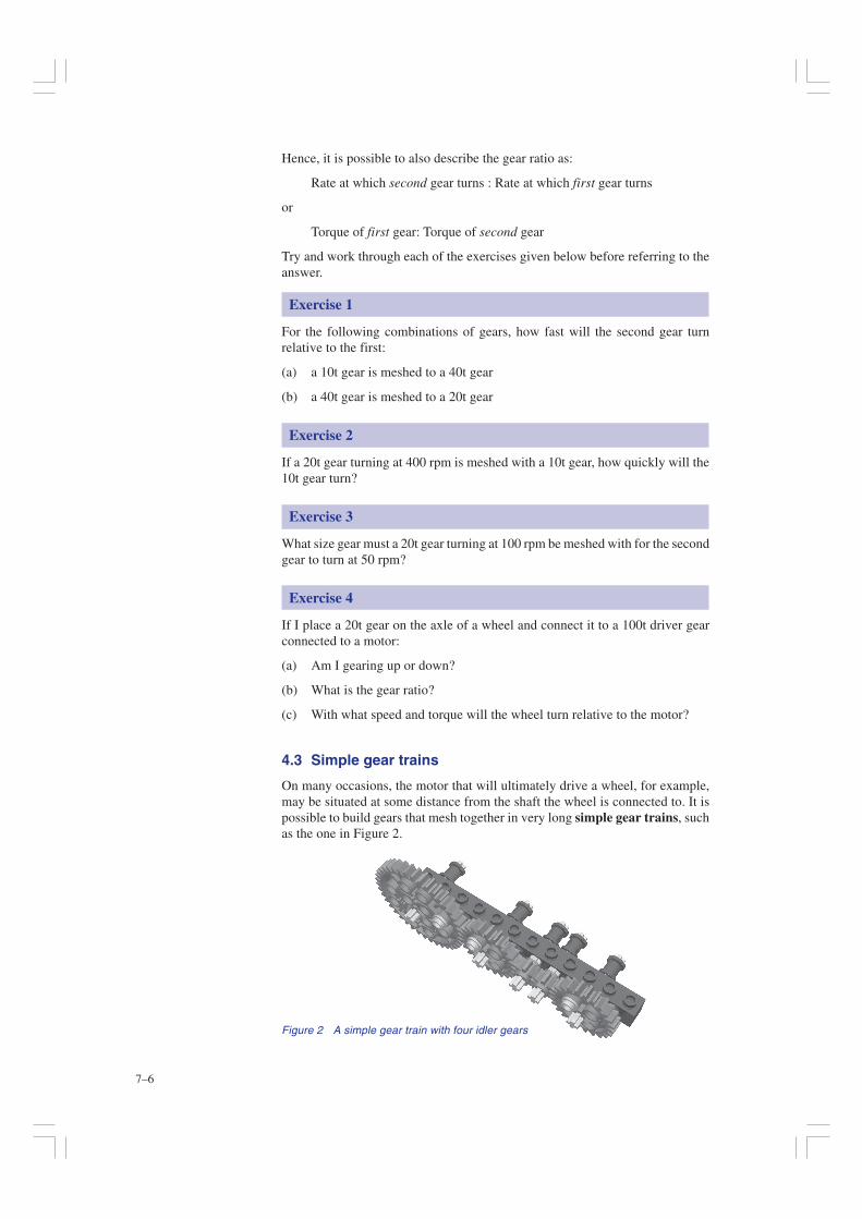
4.3 Simple gear trains
On many occasions, the motor that will ultimately drive a wheel, for example,may be situated at some distance from the shaft the wheel is connected to. It ispossible to build gears that mesh together in very long simple gear trains, suchas the one in Figure 2.
Figure 2 A simple gear train with four idler gears
7–7
Exercise 5
You should recall that two gears meshed together will turn in opposite directions.Complete the following by deleting the statement that is incorrect.
(a) If there is an odd number of gears in a simple gear train, the gears at eachend will turn in the same/in opposite* directions.
(b) If there is an even number of gears in a simple gear train, the gears at eachend will turn in the same/in opposite* directions.
In a simple gear train, the ratio of the speed of the first driver gear to the speed ofthe last driven gear is given by:
Number of teeth of first gear × Rate at which first gear turns = Numberof teeth on last gear × Rate at which last gear turns
It is worth remembering that the number and size of the intervening gears in asimple gear train does not affect the overall gear ratio, only the relative directionof the first and last gears. These intervening gears are referred to as idler gears.Idler gears are gears used to add spacing between other gears in a gear trainwithout modifying the overall gear ratio, although they may modify the ultimatedirection of rotation. Idler gears can be of any size and should be placed betweenthe two gears that need spacing.
4.4 Compound gear trains
In order to get very high or very low gear ratios, a simple gear train is ofteninappropriate because we would need to combine very large and very smallgears. For example, to produce a gear ratio of 1:20 from a 40t driver gear wouldrequire the driven gear to be 20 times larger than the driver gear. That is, wewould require a 40t × 20 = 800t driven gear.
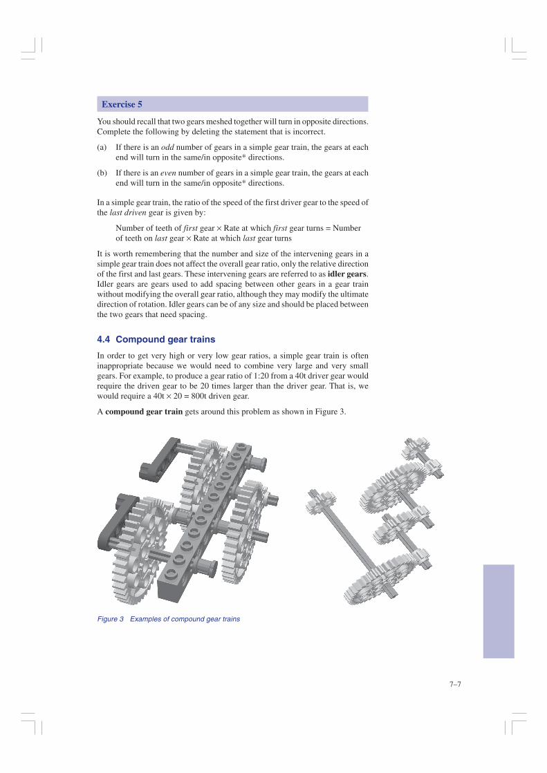
A compound gear train gets around this problem as shown in Figure 3.
Figure 3 Examples of compound gear trains
7–8
The compound gear train has two gears on some of the shafts. One of the gearsacts as a driven ‘input’. The other, differently sized, gear is used to drive thenext gear in the train. Of course, all the gears fixed onto the same shaft rotate atthe same rate – the rate of rotation of the shaft.
The compound gear train allows you to multiply gear ratios together.Consequently, it is possible to create very large gear ratios and hence generatevery large torque and low speeds from high-speed, low-torque motors, forexample.
The overall gear ratio is found by multiplying all the individual gear ratiostogether. For example, in Figure 3, two gears are connected by a compound geartrain with three stages. In the first stage, an 8t gear drives a 40t gear, giving agear ratio of 1:5 for that stage. In the second stage, an 8t gear drives a 24t gear,for a ratio of 1:3. Finally, the third stage again has a ratio of 1:5. The overall gearratio is found by multiplying the gear ratio of each stage together. If you treateach ratio as a fraction, these can be multiplied together and the overall gearratio identified. That is, write the first ratio, 1:5, as the fraction 1/5; the secondratio, 1:3, as the fraction 1/3; and the third ratio, 1:5 again, as 1/5.
Multiplying the ‘ratios as fractions’of all three stages together gives the product:
(1/5) × (1/3) × (1/5) = 1/75
If we rewrite the resulting fraction back in the form of a ratio, we get the overallgear ratio as 1:75. What this tells us is that if the right-hand, 16t gear turns oncea second, the left-hand 16t gear will not even have completed a single revolutionafter a minute (it takes 75 seconds to complete a single revolution). However,there will be a large amount of torque available from the left-hand gear; in fact75 times more than was provided by the right-hand gear.
Additional gear pairs can be added to the compound gear train, introducing anadditional multiplication step in the gear ratio calculation each time.
Exercise 6
What will the overall gear ratio be if a 40t gear drives a 10t gear, which ismounted on the same axle as another 40t gear driving a final 10t gear? Is thisgearing up or gearing down?
Exercise 7
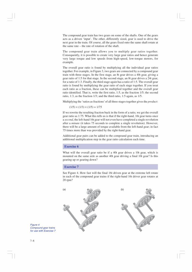
See Figure 4. How fast will the final 16t driven gear at the extreme left rotatein each of the compound gear trains if the right-hand 16t driver gear rotates at20 rpm?
Figure 4Compound gear trainsfor use with Exercise 7
(a) (b)