Gears and Gear Trains Chapter 13 Part 1faculty.mercer.edu/jenkins_he/documents/Gears1R2.pdf ·...
31
Gears and Gear Trains Chapter 13 Part 1
Transcript of Gears and Gear Trains Chapter 13 Part 1faculty.mercer.edu/jenkins_he/documents/Gears1R2.pdf ·...
Gears and Gear Trains
Chapter 13
Part 1
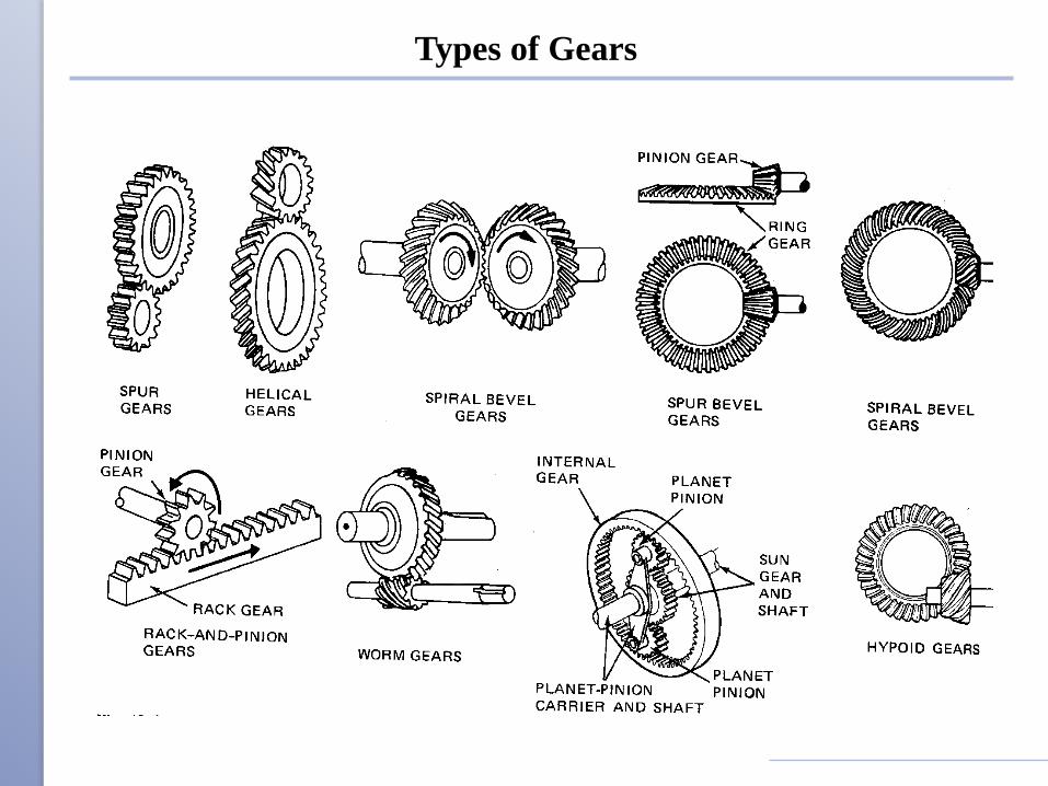
Types of Gears
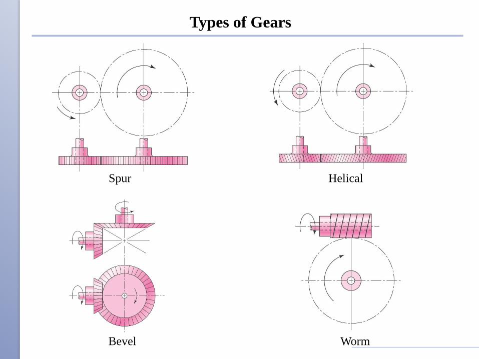
Types of Gears
Spur Helical
Bevel Worm
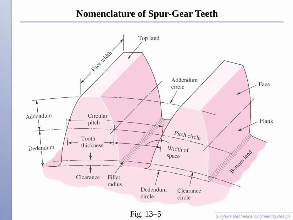
Nomenclature of Spur-Gear Teeth
Shigley’s Mechanical Engineering DesignFig. 13–5
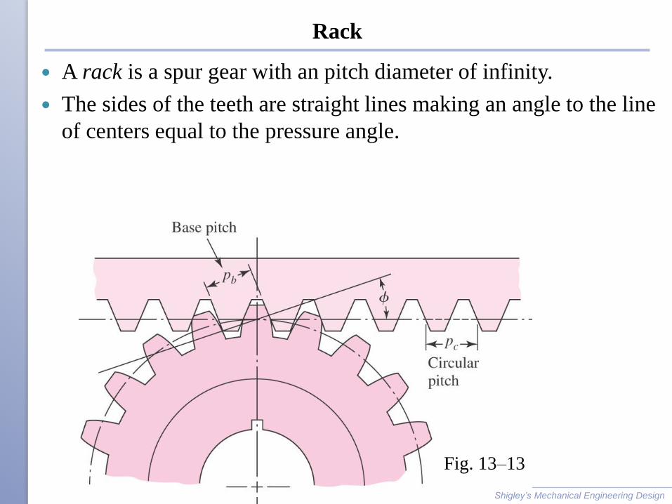
Rack
A rack is a spur gear with an pitch diameter of infinity.
The sides of the teeth are straight lines making an angle to the line
of centers equal to the pressure angle.
Shigley’s Mechanical Engineering Design
Fig. 13–13
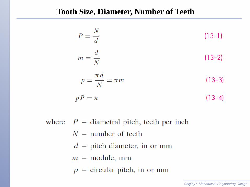
Tooth Size, Diameter, Number of Teeth
Shigley’s Mechanical Engineering Design
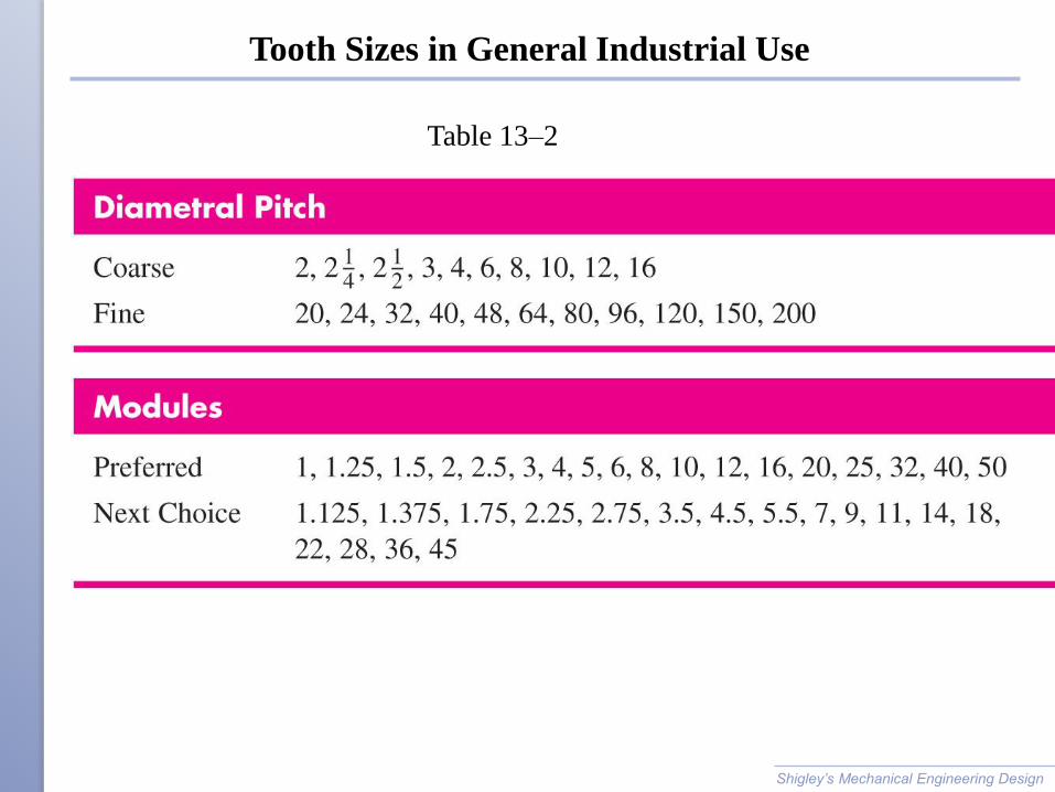
Tooth Sizes in General Industrial Use
Shigley’s Mechanical Engineering Design
Table 13–2
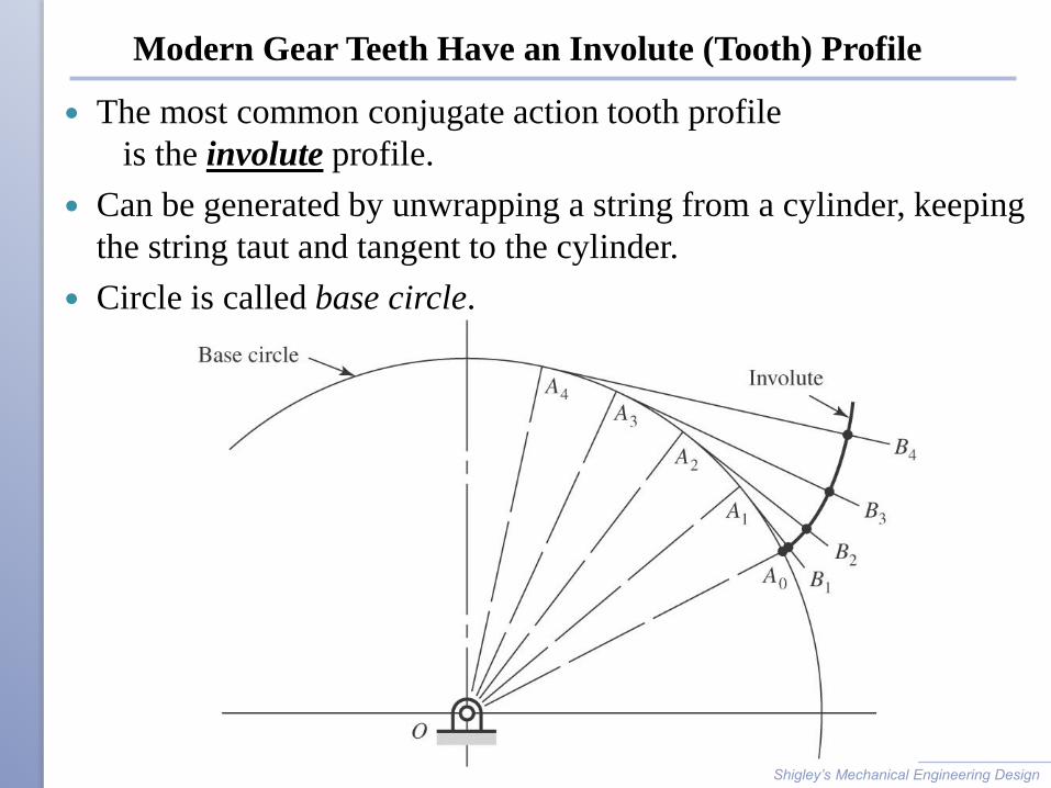
Modern Gear Teeth Have an Involute (Tooth) Profile
The most common conjugate action tooth profile
is the involute profile.
Can be generated by unwrapping a string from a cylinder, keeping
the string taut and tangent to the cylinder.
Circle is called base circle.
Shigley’s Mechanical Engineering Design
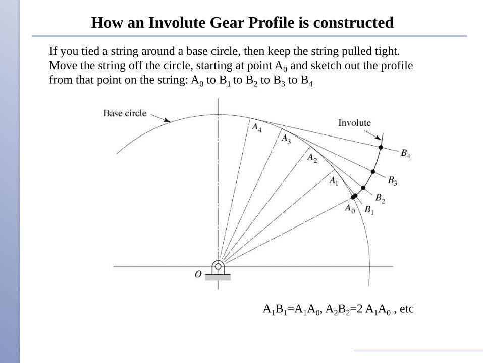
How an Involute Gear Profile is constructed
If you tied a string around a base circle, then keep the string pulled tight.
Move the string off the circle, starting at point A0 and sketch out the profile
from that point on the string: A0 to B1 to B2 to B3 to B4
A1B1=A1A0, A2B2=2 A1A0 , etc
Why would we want an involute tooth surface?
Shigley’s Mechanical Engineering Design
• Constant speed ratio between gears
• Smoother speeds
• Constant line of action of forces between gears
• Which means constant torque transmitted
• Theoretical gear-to-gear contact at tangents of
pitch circles
• Allow multiple teeth to be in contact
• Higher loads (spreads loads over more teeth)
• Tolerant of center distance errors, keeps constant
speed even if shaft/gears are not exactly perfect.
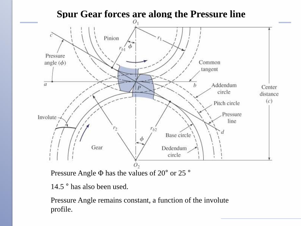
Spur Gear forces are along the Pressure line
Pressure Angle Φ has the values of 20° or 25 °
14.5 ° has also been used.
Pressure Angle remains constant, a function of the involute
profile.
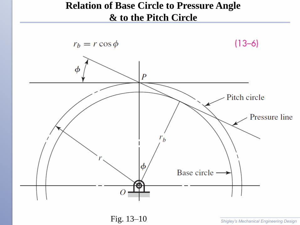
Relation of Base Circle to Pressure Angle
& to the Pitch Circle
Shigley’s Mechanical Engineering DesignFig. 13–10
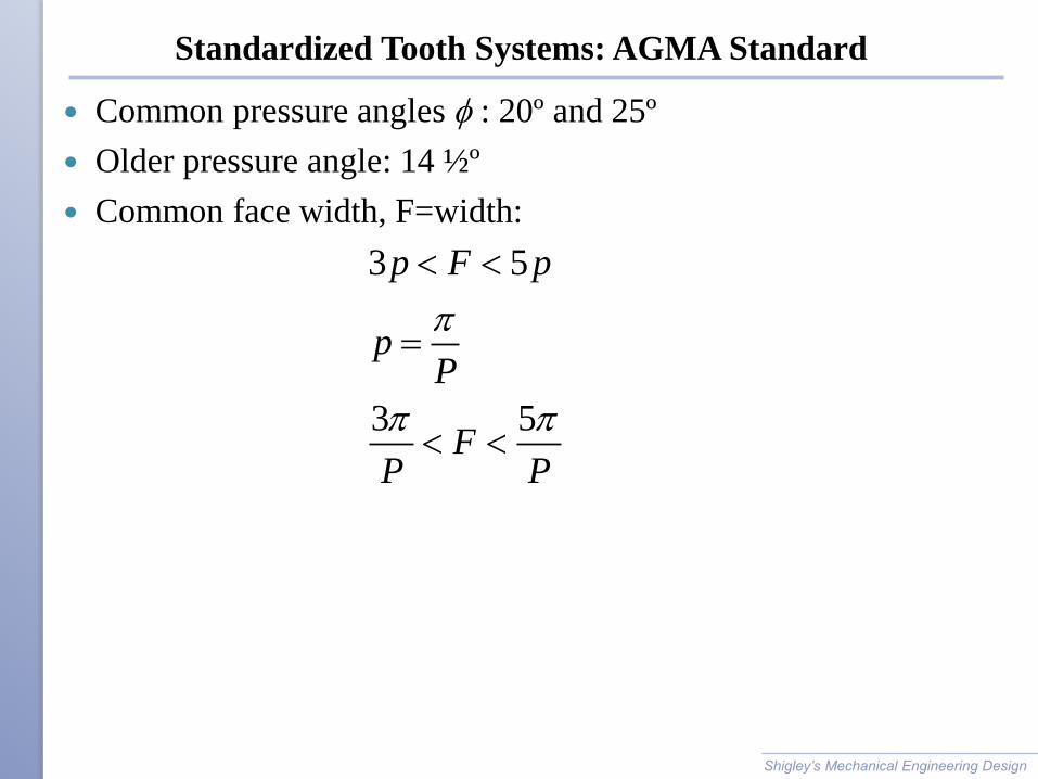
Standardized Tooth Systems: AGMA Standard
Common pressure angles f : 20º and 25º
Older pressure angle: 14 ½º
Common face width, F=width:
Shigley’s Mechanical Engineering Design
3 5
3 5
p F p
pP
FP P
=
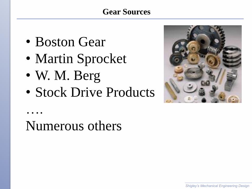
Gear Sources
Shigley’s Mechanical Engineering Design
• Boston Gear
• Martin Sprocket
• W. M. Berg
• Stock Drive Products
….
Numerous others
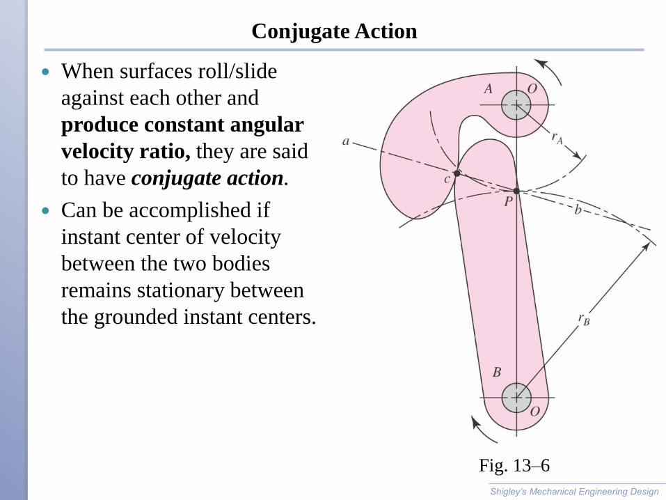
Conjugate Action
When surfaces roll/slide
against each other and
produce constant angular
velocity ratio, they are said
to have conjugate action.
Can be accomplished if
instant center of velocity
between the two bodies
remains stationary between
the grounded instant centers.
Shigley’s Mechanical Engineering Design
Fig. 13–6
Fundamental Law of Gearing:
Shigley’s Mechanical Engineering Design
The common normal of the tooth
profiles at all points within the mesh
must always pass through a fixed point
on the line of the centers called pitch
point. Then the gearset’s velocity ratio
will be constant through the mesh and
be equal to the ratio of the gear radii.
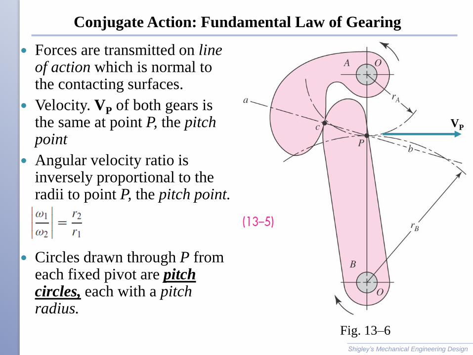
Conjugate Action: Fundamental Law of Gearing
Forces are transmitted on line of action which is normal to the contacting surfaces.
Velocity. VP of both gears is the same at point P, the pitch point
Angular velocity ratio is inversely proportional to the radii to point P, the pitch point.
Circles drawn through P from each fixed pivot are pitch circles, each with a pitch radius.
Shigley’s Mechanical Engineering Design
Fig. 13–6
VP
Gear Ratio
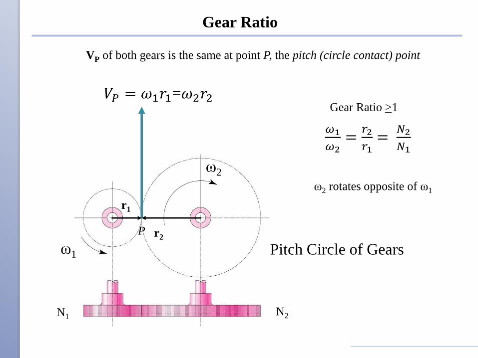
𝑉𝑃 = 𝜔1𝑟1=𝜔2𝑟2
𝜔1
𝜔2=
𝑟2
𝑟1=
𝑁2
𝑁1
Gear Ratio >1
VP of both gears is the same at point P, the pitch (circle contact) point
ω1
ω2
r2
r1
P
N2N1
ω2 rotates opposite of ω1
Pitch Circle of Gears
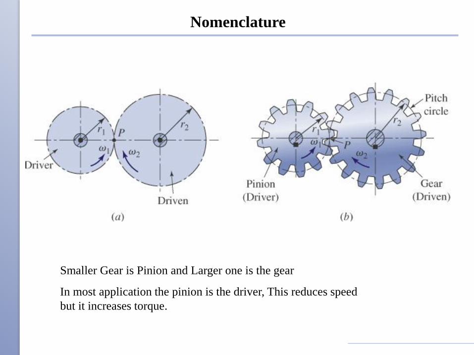
Nomenclature
Smaller Gear is Pinion and Larger one is the gear
In most application the pinion is the driver, This reduces speed
but it increases torque.
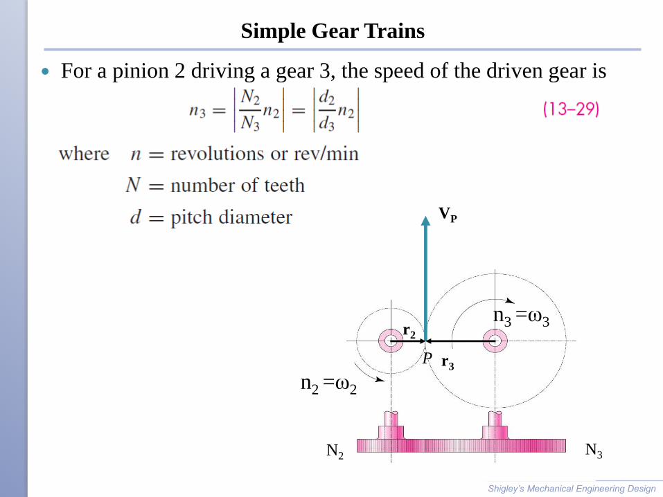
Simple Gear Trains
For a pinion 2 driving a gear 3, the speed of the driven gear is
Shigley’s Mechanical Engineering Design
n2 =ω2
n3 =ω3
r3
r2
P
N3N2
VP
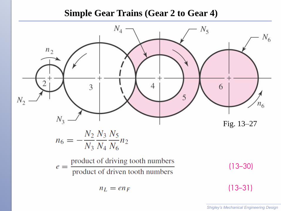
Simple Gear Trains (Gear 2 to Gear 4)
Shigley’s Mechanical Engineering Design
Fig. 13–27
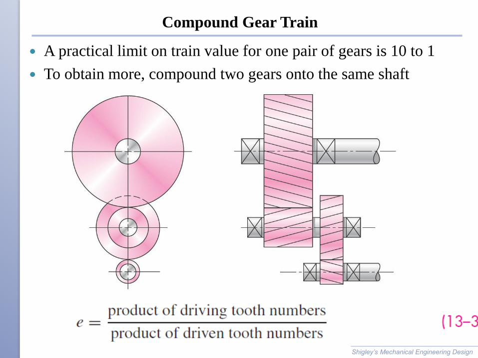
Compound Gear Train
A practical limit on train value for one pair of gears is 10 to 1
To obtain more, compound two gears onto the same shaft
Shigley’s Mechanical Engineering Design
Fig. 13–28
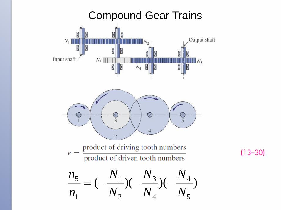
Compound Gear Trains
))()((5
4
4
3
2
1
1
5
N
N
N
N
N
N
n
n−−−=
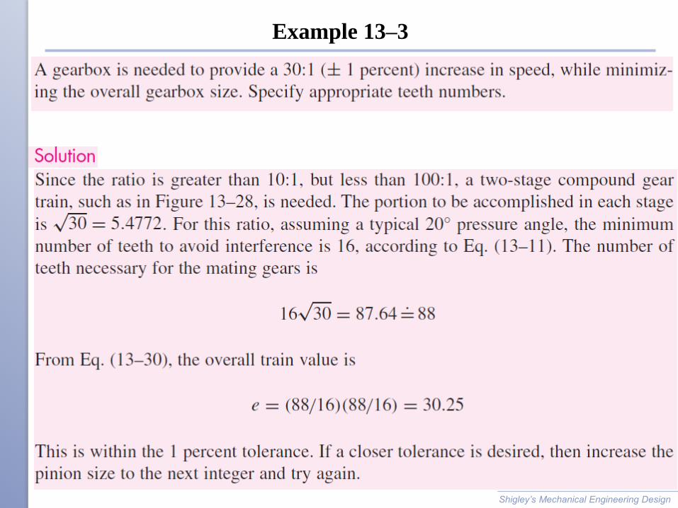
Example 13–3
Shigley’s Mechanical Engineering Design
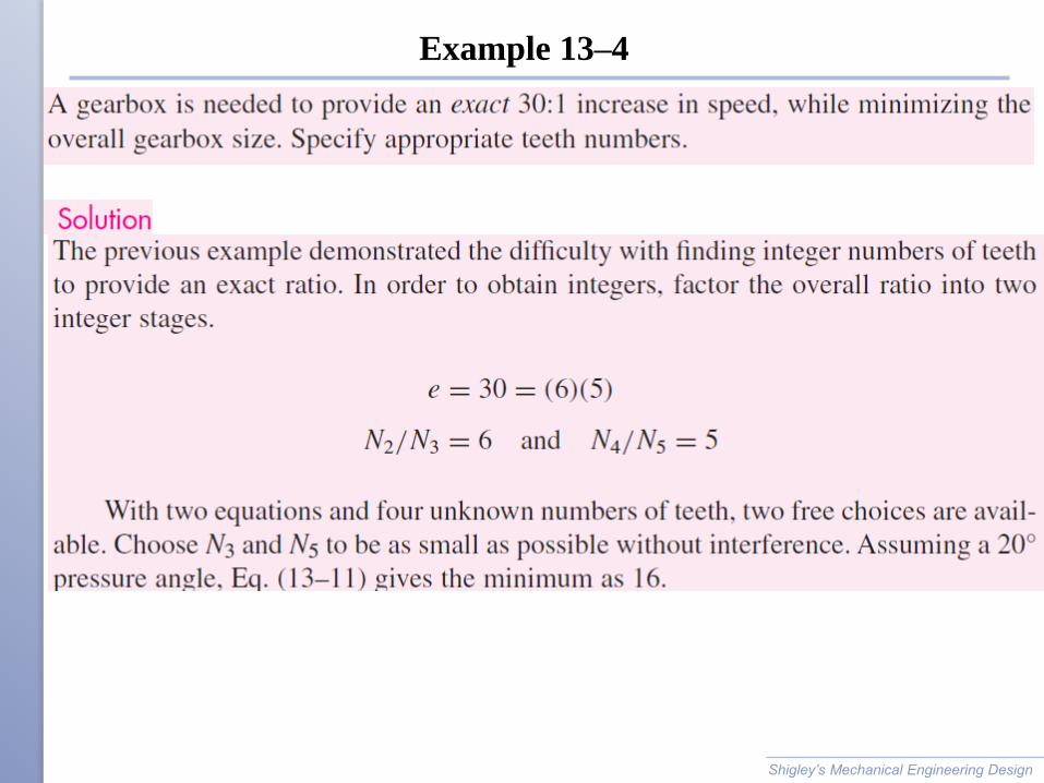
Example 13–4
Shigley’s Mechanical Engineering Design
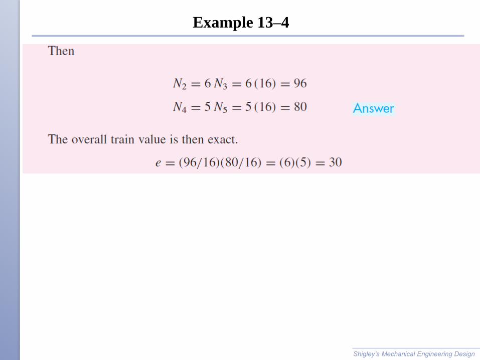
Example 13–4
Shigley’s Mechanical Engineering Design
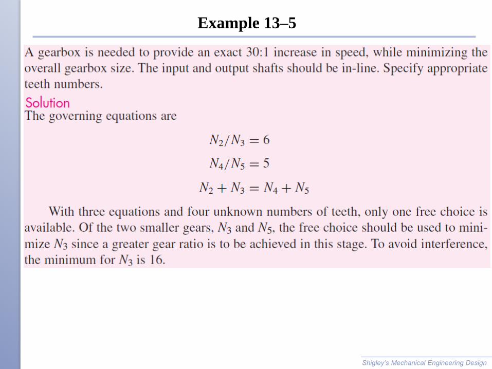
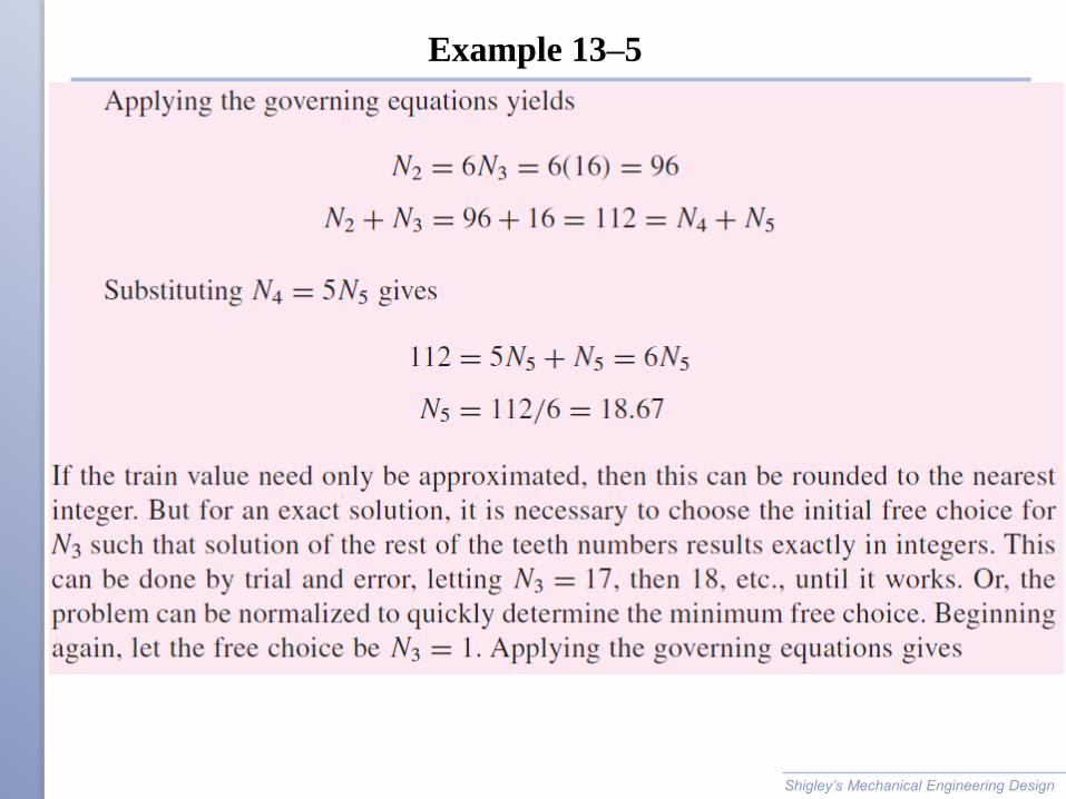
Example 13–5
Shigley’s Mechanical Engineering Design
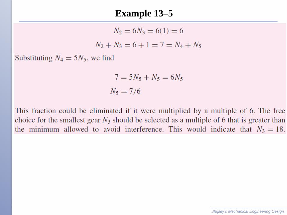
Example 13–5
Shigley’s Mechanical Engineering Design
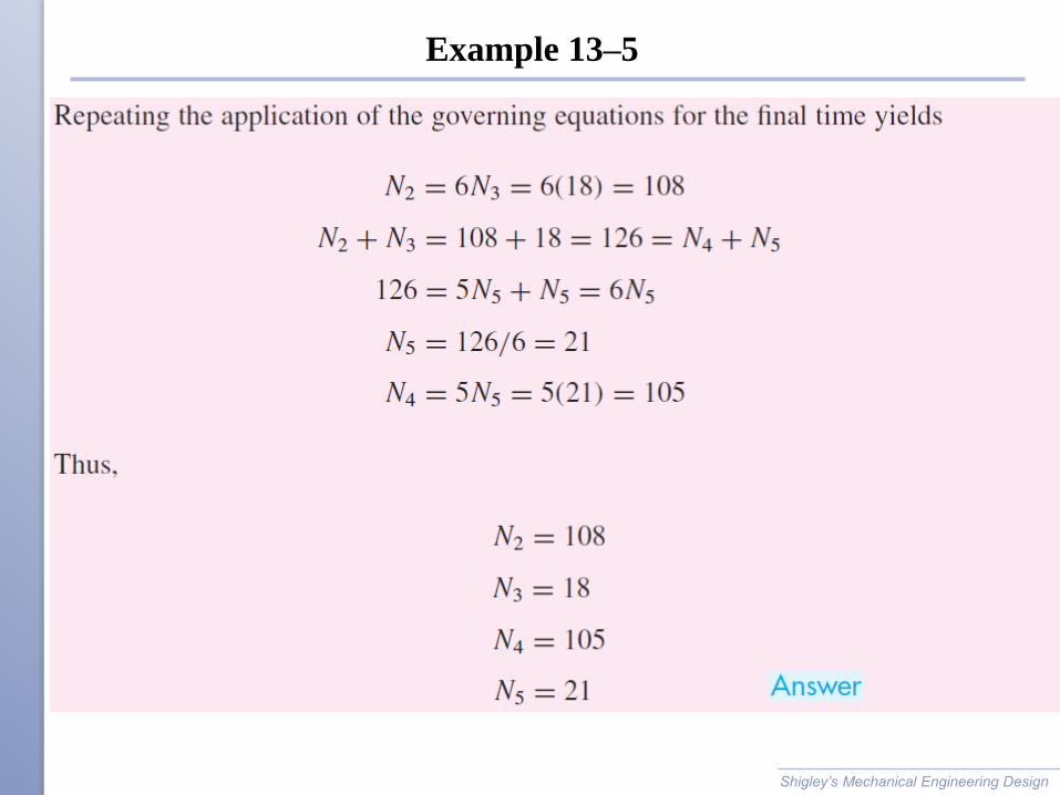
Example 13–5
Shigley’s Mechanical Engineering Design
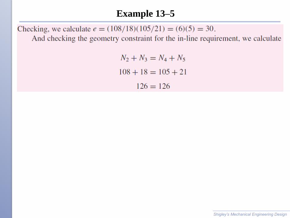
Example 13–5
Shigley’s Mechanical Engineering Design
Example 13–5
Shigley’s Mechanical Engineering Design