Gearbox Reliability Collaborative - NREL · No. Measurement Quantity Derivation 1 Ring external...
13
NREL is a national laboratory of the U.S. Department of Energy, Office of Energy Efficiency & Renewable Energy, operated by the Alliance for Sustainable Energy, LLC. Contract No. DE-AC36-08GO28308 Gearbox Reliability Collaborative: Test and Model Investigation of Sun Orbit and Planet Load Share in a Wind Turbine Gearbox Preprint William LaCava and Jonathan Keller National Renewable Energy Laboratory Brian McNiff McNiff Light Industries To be presented at the 53 rd Structures, Structural Dynamics and Materials Conference (SDM) Honolulu, Hawaii April 23 – 26, 2012 Conference Paper NREL/CP-5000-54618 April 2012
Transcript of Gearbox Reliability Collaborative - NREL · No. Measurement Quantity Derivation 1 Ring external...
NREL is a national laboratory of the U.S. Department of Energy, Office of Energy Efficiency & Renewable Energy, operated by the Alliance for Sustainable Energy, LLC.
Contract No. DE-AC36-08GO28308
Gearbox Reliability Collaborative: Test and Model Investigation of Sun Orbit and Planet Load Share in a Wind Turbine Gearbox Preprint William LaCava and Jonathan Keller National Renewable Energy Laboratory
Brian McNiff McNiff Light Industries
To be presented at the 53rd Structures, Structural Dynamics and Materials Conference (SDM) Honolulu, Hawaii April 23 – 26, 2012
Conference Paper NREL/CP-5000-54618 April 2012
NOTICE
The submitted manuscript has been offered by an employee of the Alliance for Sustainable Energy, LLC (Alliance), a contractor of the US Government under Contract No. DE-AC36-08GO28308. Accordingly, the US Government and Alliance retain a nonexclusive royalty-free license to publish or reproduce the published form of this contribution, or allow others to do so, for US Government purposes.
This report was prepared as an account of work sponsored by an agency of the United States government. Neither the United States government nor any agency thereof, nor any of their employees, makes any warranty, express or implied, or assumes any legal liability or responsibility for the accuracy, completeness, or usefulness of any information, apparatus, product, or process disclosed, or represents that its use would not infringe privately owned rights. Reference herein to any specific commercial product, process, or service by trade name, trademark, manufacturer, or otherwise does not necessarily constitute or imply its endorsement, recommendation, or favoring by the United States government or any agency thereof. The views and opinions of authors expressed herein do not necessarily state or reflect those of the United States government or any agency thereof.
Available electronically at http://www.osti.gov/bridge
Available for a processing fee to U.S. Department of Energy and its contractors, in paper, from:
U.S. Department of Energy Office of Scientific and Technical Information P.O. Box 62 Oak Ridge, TN 37831-0062 phone: 865.576.8401 fax: 865.576.5728 email: mailto:[email protected]
Available for sale to the public, in paper, from:
U.S. Department of Commerce National Technical Information Service 5285 Port Royal Road Springfield, VA 22161 phone: 800.553.6847 fax: 703.605.6900 email: [email protected] online ordering: http://www.ntis.gov/help/ordermethods.aspx
Cover Photos: (left to right) PIX 16416, PIX 17423, PIX 16560, PIX 17613, PIX 17436, PIX 17721
Printed on paper containing at least 50% wastepaper, including 10% post consumer waste.
1
Gearbox Reliability Collaborative: Test and Model Investigation of Sun Orbit and Planet Load Share in a Wind
Turbine Gearbox
William LaCava1, Jonathan Keller2
NREL, Golden, CO, 80401
and
Brian McNiff3
McNiff Light Industries, Harborside, ME, 04642
This paper analyzes experimental measurement of the sun pinion orbit during dynamometer testing and describes its relationship to the other measured responses of the planetary stage. The relationships of the sun orbit to component runout, component flexibility, gear coupling alignment, planet load share, and planet position error are investigated. Equations describing the orbit of the sun gear in the test cases are derived. Rigid and flexible multibody models of the full gearbox are investigated and compared to sun and planet measurements. This paper shows that the sun gear's path may be influenced by gear coupling responses and gearbox structural flexibilities.
Nomenclature DOE = U.S. Department of Energy DOF = degrees of freedom GRC = Gearbox Reliability Collaborative np = n times per revolution nD = n dimensional NREL = National Renewable Energy Laboratory kW = kilowatt MW = megawatt dyno = dynamometer t = time FFT = Fast Fourier Transform mesh = contact of two or more gear teeth
I. Introduction he National Renewable Energy Laboratory (NREL) / U.S. Department of Energy (DOE) Gearbox Reliability Collaborative (GRC) has been reviewing the design process of wind turbine gearboxes to identify ways to
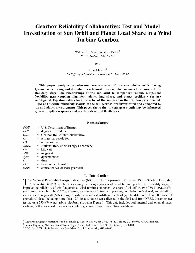
improve the reliability of this fundamental wind turbine component. As part of this effort, two 750-kilowatt (kW) gearboxes, henceforth the GRC gearboxes, were removed from an operating population, redesigned, and rebuilt to meet current megawatt (MW) design standards using state-of-the-art technology. To date, more than 500 hours of operational data, including more than 125 signals, have been collected in the field and from NREL dynamometer testing on a 750-kW wind turbine platform, shown in Figure 1. This data includes both internal and external loads, motions, deflections, and other responses during a broad range of operating conditions.
1 Research Engineer, National Wind Technology Center, 1617 Cole Blvd. /3811, Golden, CO, 80403, AIAA Member. 2 Senior Engineer, National Wind Technology Center, 1617 Cole Blvd./3811, Golden, CO, 80403 3 CEO, McNiff Light Industries, 43 Dog Island Road, Harborside, ME, 04642
T
2
Figure 1. Drivetrain of GRC 750 kW turbine. Illustration by Cisco Oyague, NREL.
The gearbox rebuilds included the implementation of a floating sun configuration in the planetary stage. Allowing the ring, carrier, or sun to float has been shown to improve planet load sharing1,2,7. Singh2 developed the equations to determine the necessary amount of float and for the planet load sharing forces resulting from planet pin position error. For a three-planet system, like the GRC gearbox, the load paths are statically determinant, and therefore, manufacturing errors should be perfectly shared as long as there is enough float to compensate for total tangential error in the planet positions. Conversely, inadequate float will result in unequal planet load sharing that can be solved statically as a function of the planet bearing stiffness and the position error of the planets.
Hidaka1 explored the precession of the sun gear in a Stoekicht planetary set using a two dimensional (2D) model with runout errors in the planet, sun, and ring gears. It showed that the center of the sun gear moves in a trochoidal pattern. Boguski4 explored the change in this pattern due to seeded planet position errors. In the 2D problem, the variations in sun orbit are functions of the error contribution of each mating gear, its mesh phasing behavior, and the number and phasing of the planet gears.
For the general case of a planetary stage experiencing torque-only loading, current literature1-3,5-8 has described the 2D load sharing characteristics of a generic planetary stage with n planets. A number of differences between the gearboxes used in these models and wind turbine gearboxes should be noted. First, in a wind turbine drivetrain application, the large overhung weight of the rotor imparts large bending loads on the gearbox. The common three-point drivetrain configuration (see Figure 1) is sensitive to these loads. Data from GRC testing has shown that these loads cause misalignment of the gear meshes9. Second, in the GRC gearbox, tandem rows of cylindrical roller bearings (CRBs) support each planet; whereas, the gearboxes in the aforementioned studies used needle bearings, or the bearings were included only as a lumped stiffness. In the GRC gearbox, the loading on the row of planet bearings can be uneven, with higher radial forces upwind, as shown in Figure 4. These loads result in planet gear tilt, which can contribute to errors in the gear mesh and affect the orbit of the sun gear. Third, wind turbine gearboxes operate at lower speeds, higher loads, and with larger deflections than many of the gearboxes investigated in these studies. Therefore, the flexibility of the structures may play a larger role. This paper analyzes experimental measurement of the sun gear's orbit in dynamometer testing and describes its relationship to the other measured responses of the planetary stage. The response of the planetary stage in a number of test cases will be analyzed. The relationship between the measured carrier motion, planet tilt, main shaft bending, gear mesh alignment, pin load distribution, planet position error, and sun gear orbit will be investigated. Equations describing the orbit of the sun gear are derived. A full six degrees of freedom (DOF) multi-body model of the planetary stage will be presented and used to validate the data analysis. The model fidelity needed to accurately predict the sun gear precession will be described.
3
II. Measurement Setup The gearboxes were heavily instrumented in the
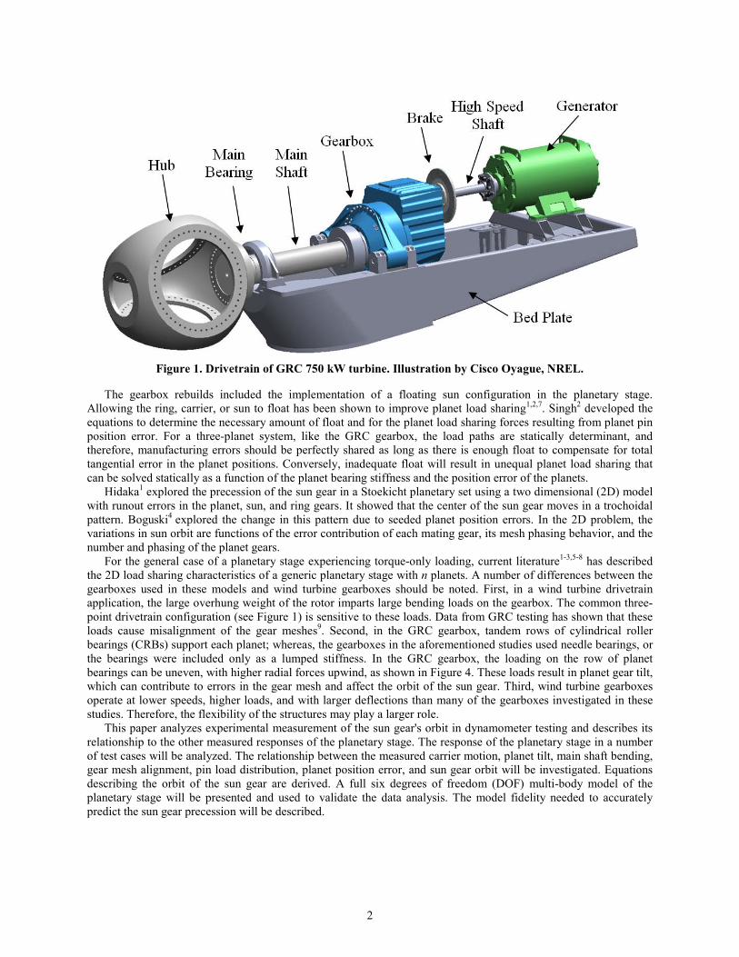
planetary stage due to the high number of failures historically originating in this stage10. The planetary stage configuration is common in commercially-produced wind turbine drivetrains due to its high power capacity and compact size. The types of measurements taken of the planetary stage during testing are shown in Figure 2 and listed in Table 1.
Proximity sensors were mounted onto the carrier to measure the radial motion of the sun gear in two directions at a location upwind of the sun-planet mesh, as shown in Figure 3 and listed as Number 4 in Table 1. Data was collected at 100 Hz in the field and dynamometer.
Figure 2. Schematic of instrumentation in planetary
stage.
Table 1. Description of instrumentation in the planetary stage
No. Measurement Quantity Derivation 1 Ring external root
strain 8 External measurement of gear face width load
distribution 2 Planet rim axial
motion 6 Three DOF displacement of planet gears with
respect to (w.r.t.) carrier 3 Planet bearing load 36 Planet axial distribution of radial load, planet load
share (Kγ)11 4 Sun proximity 2 Two DOF sun gear orbit 5 Carrier rim
proximity 6 Five DOF carrier motion w.r.t. housing, rim
deformation w.r.t. housing 6 Ring gear root
strain 24 Ring gear load distribution at 0°, 120°, and 240°
azimuth, Khß 12, load centroid
Figure 3. (left) Instrumentation schematic of sun gear for radial measurement, Illustration by Brian McNiff,
MLI; (right) installation. NREL PIX 20257
4
III. Data Analysis
A. Data Observations In GRC testing, it has been observed that the planets experience a once-per-revolution (1p) cyclical load share
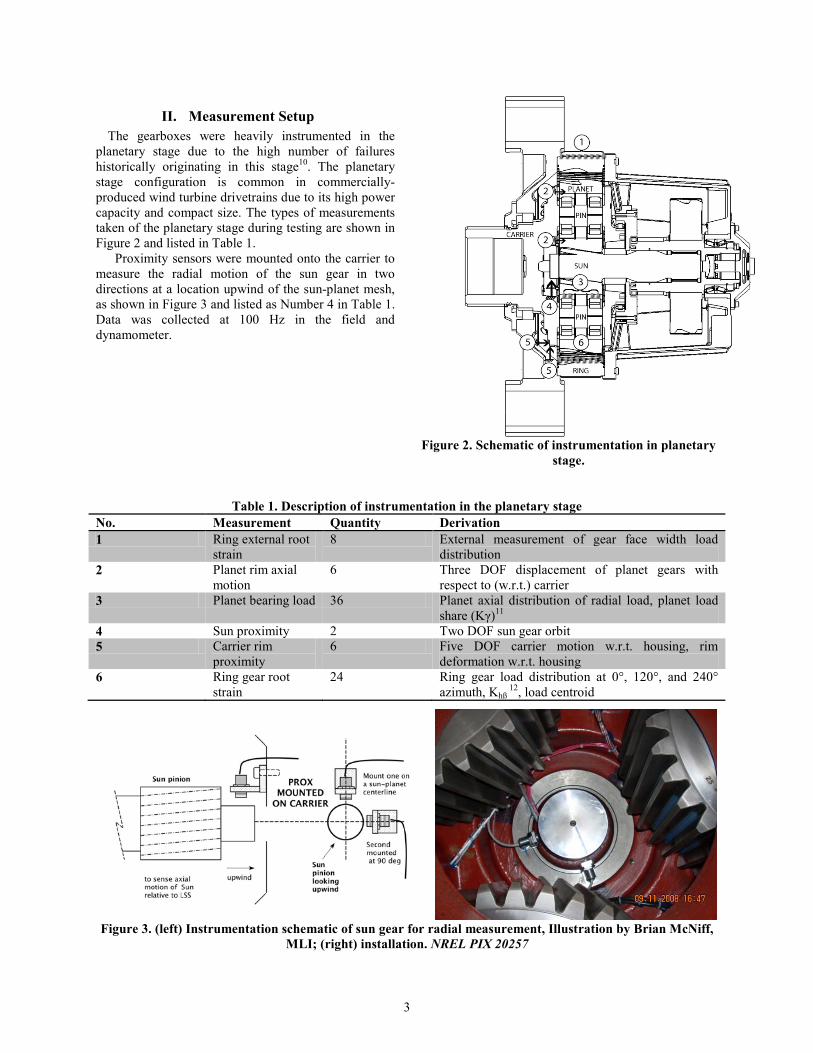
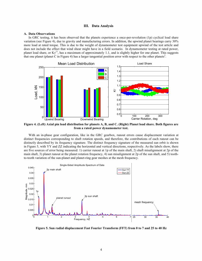
variation (see Figure 4), due to gravity and manufacturing errors. In addition, the upwind planet bearings carry 30% more load at rated torque. This is due to the weight of dynamometer test equipment upwind of the test article and does not include the effect that wind shear might have in a field scenario. In dynamometer testing at rated power, planet load share, or Kγ11, has a maximum of approximately 1.1, and is slightly higher for one planet. This suggests that one planet (planet C in Figure 4) has a larger tangential position error with respect to the other planets2.
Figure 4. (Left) Axial pin load distribution for planets A, B, and C. (Right) Planet load share. Both figures are
from a rated power dynamometer test.
With an in-phase gear configuration, like in the GRC gearbox, runout errors cause displacement variation at distinct frequencies corresponding to shaft rotation speeds, and therefore, the contributions of each runout can be distinctly described by its frequency signature. The distinct frequency signature of the measured sun orbit is shown in Figure 5, with YY and ZZ indicating the horizontal and vertical directions, respectively. As the labels show, there are five sources of error being measured: 1) carrier runout at 1p of the main shaft, 2) shaft misalignment at 2p of the main shaft, 3) planet runout at the planet rotation frequency, 4) sun misalignment at 2p of the sun shaft, and 5) tooth-to-tooth variation of the sun-planet and planet-ring gear meshes at the mesh frequency.
Figure 5. Sun radial displacement Fast Fourier Transform (FFT) from 0 to 7 and 25 to 40 Hz
Upwind Bearing Downwind Bearing0
50
100
150
200
250
Load
, kN
Mean Load Distribution
ABC
0 100 200 3000.5
0.6
0.7
0.8
0.9
1
1.1
1.2
1.3
1.4
1.5Load Share
Kγ
Carrier Rotation, deg
0 1 2 3 4 5 6 70
0.005
0.01
0.015
0.02
0.025
0.03
0.035
0.04
0.045Single-Sided Amplitude Spectrum of Data
Frequency, HZ
Mag
nitu
de, m
m
Sun YYSun ZZ
1p
2p sun shaftplanet runout
2p main shaft
25 30 35 40
mesh frequency
5
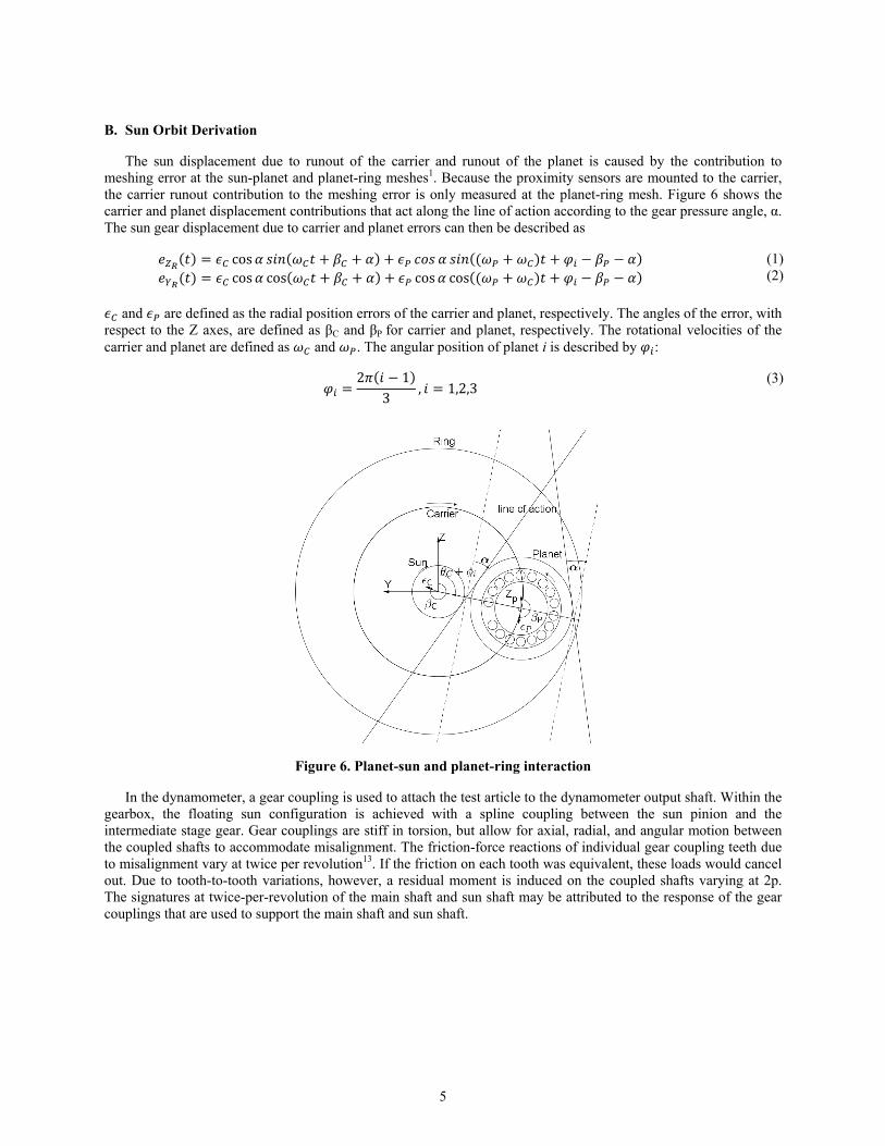
B. Sun Orbit Derivation
The sun displacement due to runout of the carrier and runout of the planet is caused by the contribution to meshing error at the sun-planet and planet-ring meshes1. Because the proximity sensors are mounted to the carrier, the carrier runout contribution to the meshing error is only measured at the planet-ring mesh. Figure 6 shows the carrier and planet displacement contributions that act along the line of action according to the gear pressure angle, α. The sun gear displacement due to carrier and planet errors can then be described as ( ) cos ( ) (( ) ) ( ) cos cos( ) cos cos(( ) )
(1) (2)
and are defined as the radial position errors of the carrier and planet, respectively. The angles of the error, with respect to the Z axes, are defined as βC and βP for carrier and planet, respectively. The rotational velocities of the carrier and planet are defined as and . The angular position of planet i is described by : 2 ( 1)3 , 1,2,3
(3)
Figure 6. Planet-sun and planet-ring interaction
In the dynamometer, a gear coupling is used to attach the test article to the dynamometer output shaft. Within the gearbox, the floating sun configuration is achieved with a spline coupling between the sun pinion and the intermediate stage gear. Gear couplings are stiff in torsion, but allow for axial, radial, and angular motion between the coupled shafts to accommodate misalignment. The friction-force reactions of individual gear coupling teeth due to misalignment vary at twice per revolution13. If the friction on each tooth was equivalent, these loads would cancel out. Due to tooth-to-tooth variations, however, a residual moment is induced on the coupled shafts varying at 2p. The signatures at twice-per-revolution of the main shaft and sun shaft may be attributed to the response of the gear couplings that are used to support the main shaft and sun shaft.
6
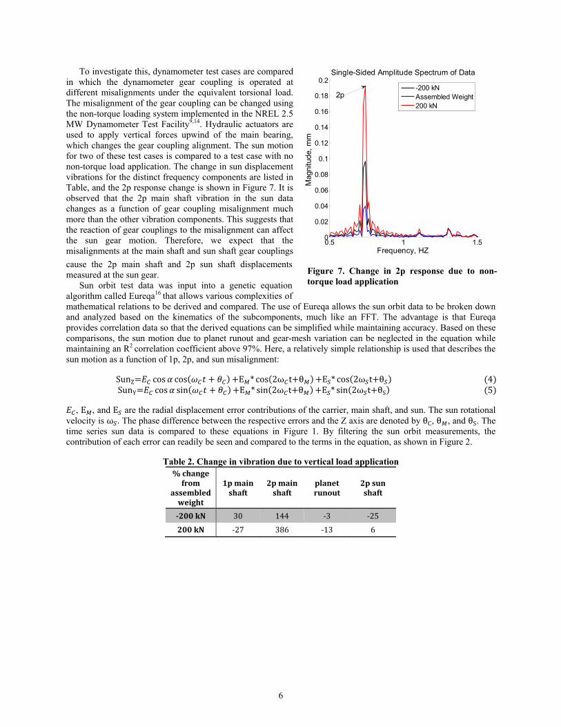
To investigate this, dynamometer test cases are compared in which the dynamometer gear coupling is operated at different misalignments under the equivalent torsional load. The misalignment of the gear coupling can be changed using the non-torque loading system implemented in the NREL 2.5 MW Dynamometer Test Facility9,14. Hydraulic actuators are used to apply vertical forces upwind of the main bearing, which changes the gear coupling alignment. The sun motion for two of these test cases is compared to a test case with no non-torque load application. The change in sun displacement vibrations for the distinct frequency components are listed in Table, and the 2p response change is shown in Figure 7. It is observed that the 2p main shaft vibration in the sun data changes as a function of gear coupling misalignment much more than the other vibration components. This suggests that the reaction of gear couplings to the misalignment can affect the sun gear motion. Therefore, we expect that the misalignments at the main shaft and sun shaft gear couplings
cause the 2p main shaft and 2p sun shaft displacements measured at the sun gear.
Sun orbit test data was input into a genetic equation algorithm called Eureqa16 that allows various complexities of mathematical relations to be derived and compared. The use of Eureqa allows the sun orbit data to be broken down and analyzed based on the kinematics of the subcomponents, much like an FFT. The advantage is that Eureqa provides correlation data so that the derived equations can be simplified while maintaining accuracy. Based on these comparisons, the sun motion due to planet runout and gear-mesh variation can be neglected in the equation while maintaining an R2
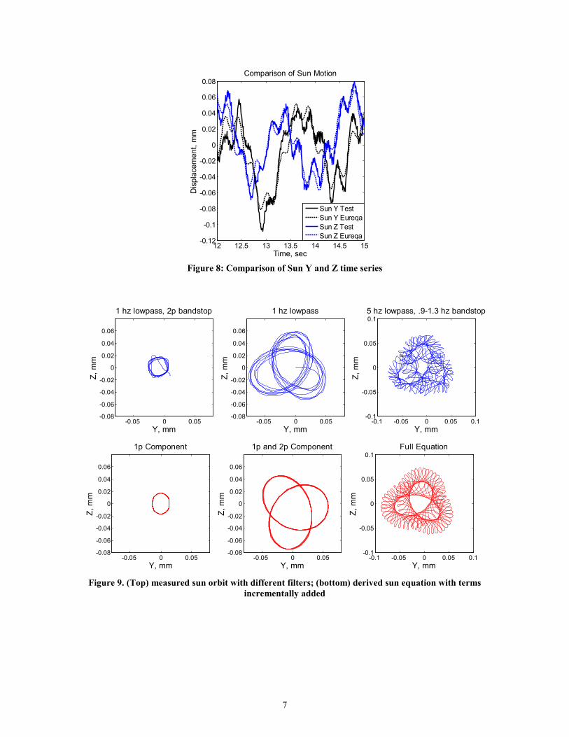
correlation coefficient above 97%. Here, a relatively simple relationship is used that describes the sun motion as a function of 1p, 2p, and sun misalignment: SunZ cos cos( ) E * cos(2ω t θ ) E * cos(2ω t θ )SunY cos sin( ) E * sin(2ω t θ ) E * sin(2ω t θS) (4)(5)
, E , and E are the radial displacement error contributions of the carrier, main shaft, and sun. The sun rotational velocity is ω . The phase difference between the respective errors and the Z axis are denoted by θC, θ , and θS. The time series sun data is compared to these equations in Figure 1. By filtering the sun orbit measurements, the contribution of each error can readily be seen and compared to the terms in the equation, as shown in Figure 2.
Table 2. Change in vibration due to vertical load application % change
from assembled
weight
1p main shaft
2p main shaft
planet runout
2p sun shaft
-200 kN 30 144 -3 -25 200 kN -27 386 -13 6
0.5 1 1.50
0.02
0.04
0.06
0.08
0.1
0.12
0.14
0.16
0.18
0.2Single-Sided Amplitude Spectrum of Data
Frequency, HZ
Mag
nitu
de,
mm
-200 kNAssembled Weight200 kN
2p
Figure 7. Change in 2p response due to non-torque load application
7
Figure 8: Comparison of Sun Y and Z time series
Figure 9. (Top) measured sun orbit with different filters; (bottom) derived sun equation with terms
incrementally added
12 12.5 13 13.5 14 14.5 15-0.12
-0.1
-0.08
-0.06
-0.04
-0.02
0
0.02
0.04
0.06
0.08Comparison of Sun Motion
Time, sec
Dis
plac
emen
t, m
m
Sun Y TestSun Y EureqaSun Z TestSun Z Eureqa
-0.1 -0.05 0 0.05 0.1-0.1
-0.05
0
0.05
0.15 hz lowpass, .9-1.3 hz bandstop
Y, mm
Z, m
m
-0.05 0 0.05-0.08
-0.06
-0.04
-0.02
0
0.02
0.04
0.06
1 hz lowpass
Y, mm
Z, m
m
-0.05 0 0.05-0.08
-0.06
-0.04
-0.02
0
0.02
0.04
0.06
1 hz lowpass, 2p bandstop
Y, mm
Z, m
m
-0.05 0 0.05-0.08
-0.06
-0.04
-0.02
0
0.02
0.04
0.06
1p Component
Y, mm
Z, m
m
-0.05 0 0.05-0.08
-0.06
-0.04
-0.02
0
0.02
0.04
0.06
1p and 2p Component
Y, mm
Z, m
m
-0.1 -0.05 0 0.05 0.1-0.1
-0.05
0
0.05
0.1Full Equation
Y, mm
Z, m
m
8
IV. Model Comparison
A. Multibody Model
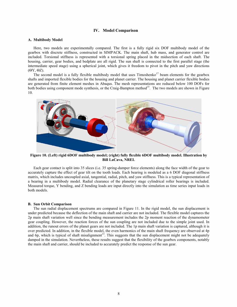
Here, two models are experimentally compared. The first is a fully rigid six DOF multibody model of the gearbox with discrete stiffness, constructed in SIMPACK. The main shaft, hub mass, and generator control are included. Torsional stiffness is represented with a torsional spring placed in the midsection of each shaft. The housing, carrier, gear bodies, and bedplate are all rigid. The sun shaft is connected to the first parallel stage (the intermediate speed stage) using a spherical joint, which gives it freedom to pivot in the pitch and yaw directions (ΘY, ΘZ).
The second model is a fully flexible multibody model that uses Timoshenko17 beam elements for the gearbox shafts and imported flexible bodies for the housing and planet carrier. The housing and planet carrier flexible bodies are generated from finite element meshes in Abaqus. The mesh representations are reduced below 100 DOFs for both bodies using component mode synthesis, or the Craig-Bampton method15. The two models are shown in Figure 10.
Figure 10. (Left) rigid 6DOF multibody model; (right) fully flexible 6DOF multibody model. Illustration by
Bill LaCava, NREL
Each gear contact is split into 35 slices (i.e. 35 spring-damper force elements) along the face width of the gear to accurately capture the effect of gear tilt on the tooth loads. Each bearing is modeled as a 6 DOF diagonal stiffness matrix, which includes uncoupled axial, tangential, radial, pitch, and yaw stiffness. This is a typical representation of a bearing in a multibody model. Radial clearance of the planetary stage cylindrical roller bearings is included. Measured torque, Y bending, and Z bending loads are input directly into the simulation as time series input loads in both models.
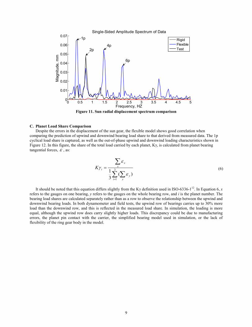
B. Sun Orbit Comparison The sun radial displacement spectrums are compared in Figure 11. In the rigid model, the sun displacement is
under predicted because the deflection of the main shaft and carrier are not included. The flexible model captures the 2p main shaft variation well since the bending measurement includes the 2p moment reaction of the dynamometer gear coupling. However, the reaction forces of the sun coupling are not included due to the simple joint used. In addition, the runout errors of the planet gears are not included. The 1p main shaft variation is captured, although it is over predicted. In addition, in the flexible model, the even harmonics of the main shaft frequency are observed at 4p and 6p, which is typical of shaft misalignment13. This suggests that the sun displacement might not be adequately damped in the simulation. Nevertheless, these results suggest that the flexibility of the gearbox components, notably the main shaft and carrier, should be included to accurately predict the response of the sun gear.
9
Figure 11. Sun radial displacement spectrum comparison
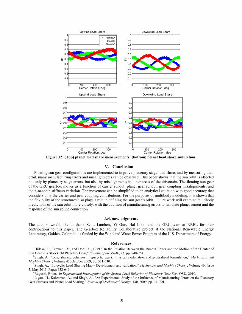
C. Planet Load Share Comparison Despite the errors in the displacement of the sun gear, the flexible model shows good correlation when comparing the prediction of upwind and downwind bearing load share to that derived from measured data. The 1p cyclical load share is captured, as well as the out-of-phase upwind and downwind loading characteristics shown in Figure 12. In this figure, the share of the total load carried by each planet, Kγ, is calculated from planet bearing tangential forces, ε , as:
∑ ∑
∑
=
= 3
1)(
31
i yy
xx
iKε
εγ
(6)
It should be noted that this equation differs slightly from the Kγ definition used in ISO-6336-112. In Equation 6, x refers to the gauges on one bearing, y refers to the gauges on the whole bearing row, and i is the planet number. The bearing load shares are calculated separately rather than as a row to observe the relationship between the upwind and downwind bearing loads. In both dynamometer and field tests, the upwind row of bearings carries up to 30% more load than the downwind row, and this is reflected in the measured load share. In simulation, the loading is more equal, although the upwind row does carry slightly higher loads. This discrepancy could be due to manufacturing errors, the planet pin contact with the carrier, the simplified bearing model used in simulation, or the lack of flexibility of the ring gear body in the model.
0 0.5 1 1.5 2 2.5 3 3.5 4 4.5 50
0.01
0.02
0.03
0.04
0.05
0.06
0.07Single-Sided Amplitude Spectrum of Data
Frequency, HZ
Mag
nitu
de, m
m
Rigid FlexibleTest
1p
2p
6p
4p
10
Figure 12: (Top) planet load share measurements; (bottom) planet load share simulation.
V. Conclusion Floating sun gear configurations are implemented to improve planetary stage load share, and by measuring their
orbit, many manufacturing errors and misalignments can be observed. This paper shows that the sun orbit is affected not only by planetary stage errors, but also by misalignments in other areas of the drivetrain. The floating sun gear of the GRC gearbox moves as a function of carrier runout, planet gear runout, gear coupling misalignments, and tooth-to-tooth stiffness variation. The movement can be simplified to an analytical equation with good accuracy that considers only the carrier and gear coupling contributions. For the purposes of multibody modeling, it is shown that the flexibility of the structures also plays a role in defining the sun gear’s orbit. Future work will examine multibody predictions of the sun orbit more closely, with the addition of manufacturing errors to simulate planet runout and the response of the sun spline connection.
Acknowledgments The authors would like to thank Scott Lambert, Yi Guo, Hal Link, and the GRC team at NREL for their contributions to this paper. The Gearbox Reliability Collaborative project at the National Renewable Energy Laboratory, Golden, Colorado, is funded by the Wind and Water Power Program of the U.S. Department of Energy.
References 1Hidaka, T., Terauchi, Y., and Dohi, K., 1979 "On the Relation Between the Runout Errors and the Motion of the Center of
Sun Gear in a Stoeckicht Planetary Gear," Bulletin of the JSME, 22, pp. 748-754 2Singh, A., “Load sharing behavior in epicyclic gears: Physical explanation and generalized formulation,” Mechanism and
Machine Theory, Volume 45, October 2009, pp. 511-530. 3Singh, A., “Epicyclic Load Sharing Map – Development and validation,” Mechanism and Machine Theory, Volume 46, Issue
5, May 2011, Pages 632-646. 4Boguski, Brian. An Experimental Investigation of the System-Level Behavior of Planetary Gear Sets. OSU, 2010. 5Ligata, H., Kahraman, A., and Singh, A., "An Experimental Study of the Influence of Manufacturing Errors on the Planetary
Gear Stresses and Planet Load Sharing," Journal of Mechanical Design, 130, 2009, pp. 041701.
0 100 200 300
0.1
0.2
0.3
0.4
0.5
0.6
0.7
0.8
0.9
1
Carrier Rotation, deg
Kγ
Upwind Load Share
Planet APlanet BPlanet C
0 100 200 300
0.1
0.2
0.3
0.4
0.5
0.6
0.7
0.8
0.9
1Downwind Load Share
Kγ
Carrier Rotation, deg
0 100 200 300
0.1
0.2
0.3
0.4
0.5
0.6
0.7
0.8
0.9
1Upwind Load Share
Kγ
Carrier Rotation, deg0 100 200 300
0.1
0.2
0.3
0.4
0.5
0.6
0.7
0.8
0.9
1Downwind Load Share
Kγ
Carrier Rotation, deg
11
6Seager, D. L., "Load Sharing Among Planet Gears," SAE Paper No. 700178, 1970. 7Botman, M., "Epicyclic Gear Vibrations," Transactions of the ASME, 97, 1976, pp. 811-815. 8Hidaka, T., Terauchi, Y., and Ishioka, K., "Dynamic Behavior of Planetary Gear -2nd Report, Displacement of Sun Gear and
Ring Gear," Bulletin of the JSME, 19, 1976, pp. 1563-1570. 9LaCava, W.; McNiff, B.; van Dam, J., “NREL Gearbox Reliability Collaborative: Comparing In-Field Gearbox Response to
Different Dynamometer Test Conditions,” WINDPOWER 2011, 23-25 May 2011, Anaheim, California. 10Musical, W.; Butterfield, S.; McNiff, B., “Improving wind Turbine Gearbox Reliability,” European Wind Energy
Conference, 7-10 May 2007, Milan, Italy. 11American Gear Manufacturers Association, ANSI/AGMA 6123-BXX, “Design Manual for Enclosed Epicyclic Gear
Drives”, AGMA, Virginia USA, 2006. 12International Organization for Standardization: ISO 6336-1:2010 “Calculation of load capacity of spur and helical gears,”
ISO Geneva CH, 2010. 13Randall, R. Vibration-Based Condition Monitoring, 1st ed., John Wiley and Sons, New York, 2011, pp. 33-34. 14Link, H., LaCava, W. Gearbox Reliability Collaborative Project Report: Findings from Phase 1 and Phase 2 Testing. 88 pp.
NREL 51885, 2011. 15Craig, R.R., Bampton M. “Coupling of substructures for dynamic analysis,” AIAA Journal, 1968; 6:1313-1319. 16Schmidt M., Lipson H., "Distilling Free-Form Natural Laws from Experimental Data," Science, Vol. 324, no. 5923, 2009,
pp. 81 - 85. 17Timoshenko, S.; Gere, J. Mechanics of Materials. Van Nostrand Reinhold Co., New York, 1972.