
Rebirth. One life? or Many lives? Rebirth One life? or Many lives?

IntroductionThe service life of a gearbox is deter-
mined by many factors. Bearings, for example, play a major role since they contribute an important function while also interacting with the shafts, casing and oil. Without a doubt, the sizing of the bearings is of great importance in gearbox reliability. For over 50 years, bearing dynamic carrying capacity has been used to determine a suitable size needed to deliver a sufficient fatigue life. But despite the existence today of ad-vanced calculation methods, they do not
fully predict service life. Producers of high-quality bearings have introduced better ways to express (quantify) im-proved performance, but only in terms of increased dynamic carrying capacity.
This article will cover the following:• Sizing of bearings based on
dynamic carrying capacity and how this relates to service life
• How the design of the interface between bearing and shafts should be adapted to modern shaft materials
• How the design of the interface between bearing and gearbox casing influences service life of the gearbox
• Influence of modern electric motor speed controls on bearing-type selection
Sizing of rolling element bearings based on dynamic carrying capacity. For modern high-quality bearings, the clas-sic basic rating life can deviate signifi-cantly from the actual service life in a given application. Generally speaking, service life in a particular application depends not only on load in relation to bearing size, but also on a variety of in-fluencing factors, including lubrication, the degree of contamination, misalign-ment, proper installation and environ-mental conditions.
The first method accepted by ISO for determining a suitable bearing size is the classic Lundberg and Palmgren equation L10 = (C/P)P, making it pos-sible to determine a suitable dynamic C-value (which in turn defines the bear-ing size) needed to satisfy a need for a fatigue life L10.
Gearbox BearingService Life:
Hans Wendeberg
(Printed with permission of the copyright holder, the American Gear Manufacturers Association, 500 Montgomery Street, Suite 350, Alexandria,Virginia 22314-1560. Statements presented in this paper are those of the author(s) and may not represent the position or opinion of the American Gear Manu-facturers Association.)
Management SummaryThe availability of high-strength
shaft materials, in combination with bearings with high carrying capacity, allows use of slimmer shafts. However, the modulus of elasticity remains the same, so seat design for bearings and gears must be given close attention.
A Matter OF
MASTERINGMany DesignParameters
Figure 1—Life adjustment factor a23 for oil film influence.
powertransmissionengineering april 2012 www.powertransmission.com38

The influence of material properties and lubricant film thickness was intro-duced in the 1960s, represented by the a23 factor (Fig. 1).
(1)L10 = a23 (C/P)P [a23 is a function of k and
the material]
As an attempt to take some of those factors into account when determin-ing a suitable bearing size, the DIN ISO281:1990/AMD2:2000 contains a modification factor aSLF to the basic rat-ing life L10 = (C/P)P. The method makes provision for bearing manufacturers to recommend a calculation methodology for this life modification factor to be applied to a bearing based on operating conditions. Some life modification fac-tors apply the concept of a fatigue load limit Pu analogous to that used when di-mensioning other machine components. Furthermore, the life modification factor makes use of the lubrication conditions and a factor ηc for contamination level to reflect the application’s operating condi-tions.
Basic ConditionsThe life modification factor considers
bearing load level, oil film thickness and the stress-inducing influence of inden-tations in raceways and rollers from oil contaminants.
The influence of the oil film thick-ness is strong, and is represented by the k–value. k is the ratio of the actual op-erating viscosity to the rated viscosity for adequate lubrication (Ref. 1).
The influence of indentations from oil contaminants is very important, and complex to model. The ηc–value (con-tamination factor) acts as an inverted stress concentration factor defined as a value between 0 and 1, where 0 repre-sents “severe contamination” and 1 rep-resents “extreme cleanliness.” The DIN ISO 281 Addendum 4:2003 describes a method to obtain an ηc–factor for a given application. SKF has developed a standardized method to estimate the ηc–value using load level; oil film thick-ness; size and type of contamination particles; mounting practice; filter ef-fectiveness; and seal effectiveness into account (Refs. 2–3).
(2)L10m = aSKF (C/P)P [aSKF ~ k, ηc, Pu, P]
SKF and other bearing producers over the last decade have introduced high-performance-class bearings that are given higher dynamic carrying ca-pacity figures and, in SKF’s case, anoth-er scale for the life modification factor aSKF to adapt L10m calculations to the new technological developments in material and manufacturing (Fig. 2).
Therefore, the development from the purely sub-surface fatigue theory—“Acta Polytechnica” from Lundberg & Palmgren (Ref. 4) equation L10 = (C/P)P—to a more realistic bearing application
model, has introduced some adjustment factors to account for other, influencing phenomena in the sizing of rolling bear-ings. Observe that by choosing how to define the different factors in relation to the operating conditions—such as lu-brication quality and oil cleanliness—it is possible to consider more effects than load, exclusively; this makes it trickier to evaluate bearings from different manu-facturers based only on published dy-namic carrying capacity figures.
Limitations of the classical and modi-fied sizing models. The different issues of the L10 models for determining bearing
Figure 2—Life adjustment factor aSKF for oil film quality, load level and indentation influence; separate “high-performance scale.”
continued
39www.powertransmission.com april 2012 powertransmissionengineering

size are well-grounded in mathematical models and practical testing, but limited in the use of only one failure mecha-nism—i.e., fatigue of the raceways or the rolling elements to deliver a suitable service life when determining a suitable bearing size. In the aSKF diagram, very thin oil film (e.g., k equal to 0.1) is asso-ciated with a life modification factor of 0.1—independent of load level—which is to be understood as predominant, surface-induced fatigue. In the bearing (and in the adjustment factor model), surface-induced fatigue gains impor-tance at low values of k and ηc.
Wear from abrasive particles in the oil film is a complex phenomenon. It will, for instance, surely change the contact geometry—which in turn will change the wear progress—so its progress is difficult to predict. Work on predictive models is in progress but will not be dis-cussed here in detail. Recent findings in the field of surface distress in the thin-film regime—applicable to bearings in the lower-speed part of gearboxes and on gears—are, however, bringing new insights that are finding practical appli-cations in bearing design and manufac-turing (Ref. 1).
Surface DistressIn many industrial applications hav-
ing lubricated rolling/sliding contacts (rolling bearings, gears, cam-followers) the power density has increased ac-cordingly, due to the need for higher efficiency, reduction of weight and costs (i.e., downsizing). However, with the increasing severity of the working condition—that is, by heavier loads in combination with higher temperatures, thinner oil films and/or boundary lu-brication conditions—machine com-ponents can sometimes suffer from sur-face distress (Ref. 5). This phenomenon manifests itself initially with a change of coloration/dull appearance of the surface, and grows as the damage pro-gresses. Under the microscope, the af-fected surface areas show the presence of tiny microspalls, microcracks or mi-cropits (Fig. 3).
Today it is recognized that surface distress is a surface damage phenom-enon associated with poor lubrication conditions, thus high, local friction and pressures at asperity level. This phenom-
Figure 4—Surface distress on asperity summits (left) and in the area around an indent (right).
Figure 5—Schematic representation of the traction discontinuities and stress concentration areas in boundary or mixed-lubrication regime of rough surfaces.
Figure 3—Surface distress.
powertransmissionengineering april 2012 www.powertransmission.com40
enon has been the subject of many re-cent experimental and numerical stud-ies (Refs. 7–12).
Surface FrictionReal contacts, even when running un-
der “nominal pure rolling” conditions, always have a small amount of slip; this results in some sliding friction and, con-sequently, in the possibility of surface distress risk. Testing has shown that nominal, pure rolling conditions can also exhibit surface distress. Under equal conditions and number of cycles, it has also been found that as the boundary friction coefficient is increased, surface distress is more severe. One easily con-cludes that boundary friction is a very important factor in promoting surface microcracks when the contact operates under boundary or mixed lubrication.
Importance of Lubrication and Roughness
Lubrication plays a major role in the life performance of rolling bearings, which is why life models account for the effect of the lubrication parameter k (Ref. 1). The importance of lubrica-tion and roughness in surface damage is very much related to the effect of lo-cal friction forces and stress concentra-tions (at asperity level). In boundary or mixed-lubrication, having irregularities (roughness or indentations, Fig. 4) on the surface will influence the way the dry and lubricated spots are distributed within the contact. Furthermore, dis-continuities on surface traction and pos-sible stress concentrations (Fig. 5) must also be considered. High roughness or high roughness slopes might promote local film collapse, high contact pres-sures and tractions. This will enhance stress concentrations in the critical areas of traction discontinuities.
Indeed, from the test results and theoretical modeling, surface distress appears first in areas of pressure dis-continuities (high-pressure gradients) associated with increased roughness. It becomes apparent on the borders of grooves or in the summits of asperities or surface rises from indentations (Fig. 4). Rather unexpectedly, it is, in general, the smoother of the two mating surfaces that will first start the distress process.
Some observations that may help to ex-plain this discussed in the next section.
The Contact of Two Rough Surfaces
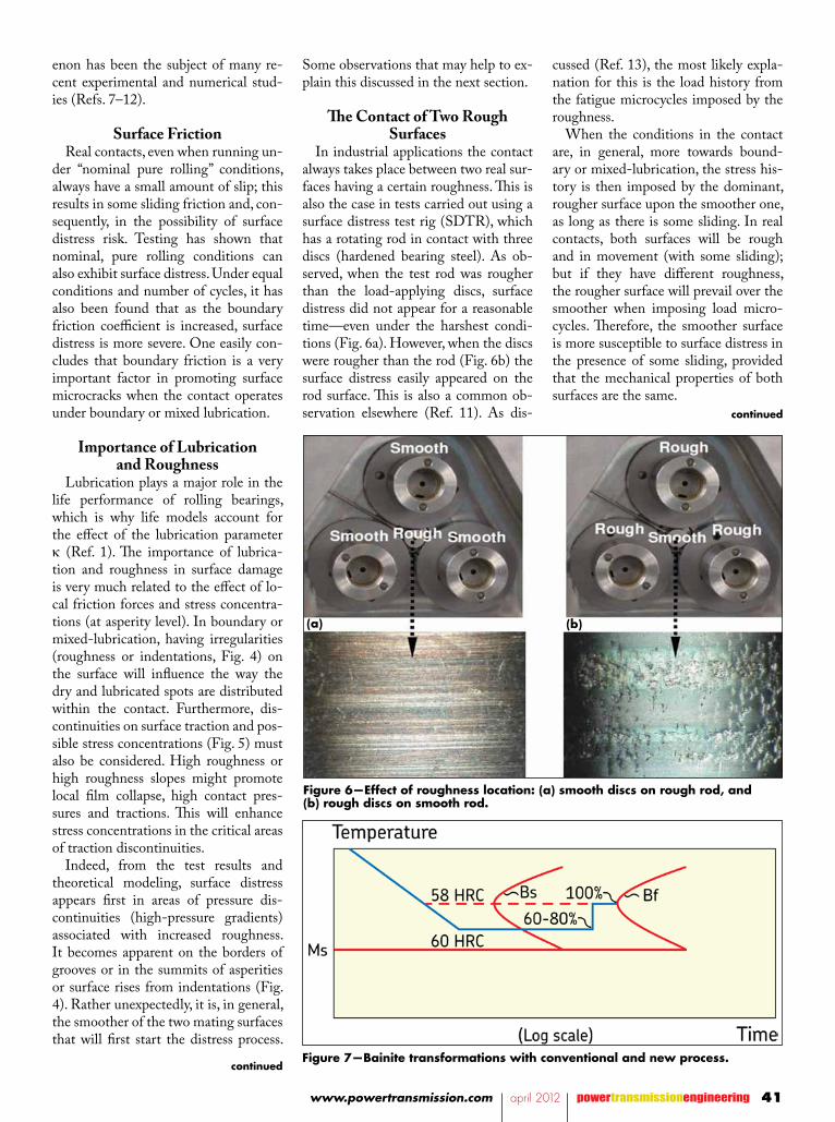
In industrial applications the contact always takes place between two real sur-faces having a certain roughness. This is also the case in tests carried out using a surface distress test rig (SDTR), which has a rotating rod in contact with three discs (hardened bearing steel). As ob-served, when the test rod was rougher than the load-applying discs, surface distress did not appear for a reasonable time—even under the harshest condi-tions (Fig. 6a). However, when the discs were rougher than the rod (Fig. 6b) the surface distress easily appeared on the rod surface. This is also a common ob-servation elsewhere (Ref. 11). As dis-
cussed (Ref. 13), the most likely expla-nation for this is the load history from the fatigue microcycles imposed by the roughness.
When the conditions in the contact are, in general, more towards bound-ary or mixed-lubrication, the stress his-tory is then imposed by the dominant, rougher surface upon the smoother one, as long as there is some sliding. In real contacts, both surfaces will be rough and in movement (with some sliding); but if they have different roughness, the rougher surface will prevail over the smoother when imposing load micro-cycles. Therefore, the smoother surface is more susceptible to surface distress in the presence of some sliding, provided that the mechanical properties of both surfaces are the same.
Figure 7—Bainite transformations with conventional and new process.
Figure 6—Effect of roughness location: (a) smooth discs on rough rod, and (b) rough discs on smooth rod.
(a) (b)
continued
continued
41www.powertransmission.com april 2012 powertransmissionengineering

Improving Wear and Metallic-Surface Contact Resistance
One way to enhance wear resistance is to increase the hardness of the com-ponents in contact. But this has conse-quences. If hardness increases, tough-ness is reduced, as well as a safe failure mode; spalling occurs instead of crack-ing, leading to catastrophic failure.
Development work was performed to find a way to improve the resistance to surface-initiated damage without los-ing the fundamental advantages of cur-rent processes. The bainite hardening used today can be manipulated to retain toughness, compressive residual stresses and—at the same time—increase wear and debris-contaminated condition life without loss of productivity. The pro-cess (patent-protected; Fig. 7) provides products with prolonged life under harsh running conditions while retain-ing all the benefits of existing long-term, successful hardening processes.
Wear tests conducted using signifi-cant amounts of debris in the form of chilled cast iron particles significantly delay the onset of heavy wear (Fig. 8).
Tests run under marginal lubrication conditions confirm the advantages of the new heat treatment method—about twice the life is attained under very low kappa conditions (Fig. 9).
This enhanced heat treatment will be-come the future standard and enhance the ability of bearing components to withstand environmental threats posed by application conditions encompassing debris contamination and marginal lu-brication.
How the design of the interface be-tween bearing and shafts should be adapted to modern shaft materials. An-other surface failure-related mecha-nism that may limit the performance of a gearbox is fretting. Modern, high-strength steels offer great possibilities for transmitting high torque and load in gearbox shafts and gears, despite limited dimensions. However, modern high-strength steel still has the same modulus of elasticity as older, lesser steel material. Hence the deflection for a given condi-tion is the same; conversely, if the in-creased stress resistance of a better shaft material is utilized, the shaft will deflect and/or twist more than if a less-stress-resistant material (resulting in a larger
Figure 9—Weibull estimates for bearings tested under severe contaminated conditions.
Figure 10—Straight shaft seat critical fretting points (Ref. 14).
Figure 8—Severe wear damage phase under contaminated conditions.
powertransmissionengineering april 2012 www.powertransmission.com42

diameter shaft) was used.To avoid damage to the joints be-
tween shafts, rings, hubs or gears, any increased shaft deflection/twisting due to downsizing requires close attention to the design of the shaft seats.
On Fretting Developing to Shaft Cracking
In a mechanical context, fretting is commonly used to describe wear and/or corrosion caused by small move-ments in interfacing, metallic surfaces. Also, surfaces that bind to each other via friction, e.g., interference fit joints, will, when the frictional binding force is overcome, move in relation to each oth-er. This motion will also cause exposure of the metallic surfaces with oxidation as result. Typically, the oxidation results in discoloring. If the relative motion is large and the contact pressure high, the relative motion may, however, develop fretting. And if the fretting occurs in a critical place on a shaft surface, it may initiate surface damage that propagates to shaft breakage (Fig. 10.)
In a rolling bearing context, bearing suppliers work with fitting practices aimed at eliminating fretting caused by bearing rings subjected to rolling element loads. In the vast majority of rolling bearing applications, this is suffi-cient because the bearings are mounted in shaft positions where the bending/torsional stress is very low. In this situa-tion, contact pressure between ring and shaft is only needed to eliminate mo-tion/fretting—mainly from the shear stress between seat and ring bore result-ing from the rolling elements.
In positions where shaft bending/twisting is more pronounced, the seats for shrunk components must be de-signed in a way that permits local mo-tion and development of a limited surface damage without risk that the surface damage propagates. Using un-complicated calculations, it is easy to show that interference between an inner ring and a shaft cannot eliminate mo-tion caused by bending and or torsion. A solution to limit and “disarm” fretting due to shaft bending/torsion has to be sought outside the interference-depen-dent contact pressure domain.
Example: More Interference is Not Always a Solution
The contact pressure between a rect-angular cross-section ring and a massive shaft when the ring is shrunk onto the shaft is expressed as a function of the ring hoop stress:
(3)p = (de - di) σhoopdi
where: de is ring inner diameter, mm di is ring outer diameter, mm
For bainitic-hardened rings, a maxi-mum hoop stress of 100 MPa is allowed from a fatigue life influence point of view; maximum contact pressure ex-pected between a bainitic-hardened inner ring and a shaft is estimated at 100 × (de – di)/di (MPa).
The inner ring dimensions of a bearing depend on the cross-section. For a typi-cal ISO diameter series 0 roller bearing, the radial thickness of the inner ring is roughly 5.5–7.5 percent of the bore diameter. Smaller bearings have rela-tively thicker rings, and vice versa. For a 500 mm bore ISO series 0 bearing, the above gives that the maximum practical contact pressure in the bore at approxi-mately 100 × (1.055 – 1)/1 = 5.5 MPa.
A heavier ring cross-section would result in a larger contact pressure, but within the ISO dimension system it is virtually impossible to find large inner rings with a radial thickness larger than 15 percent of the bore diameter. And so a ring-to-shaft contact pressure of
15 MPa is considered a practical, maxi-mum pressure to achieve.
If such a ring is sitting on a shaft seat subjected to bending and/or torsion, the bending and/or torsional strain in the surface of the shaft results in a mo-tion between shaft and ring—unless the ring is forced to develop the same strain as the shaft. If there is motion in the mating surface, fretting is likely to fol-low. The only way to eliminate all mo-tion between ring and shaft is to ensure that the surfaces “bind” to each other. In normal machines, the only binding mechanism available is friction. If fric-tion somehow results in a ring binding sufficiently to a shaft surface subjected to bending and/or torsion, the contact pressure X coefficient of friction must be larger than the shaft surface bending and/or torsion stress.
A commonly used maximum coef-ficient of friction given (for degreased and heated steel components) is 0.2. Using the above-estimated 15 MPa maximum level of contact pressure and the 0.2 coefficient of friction, the maxi-mum shaft surface bending and/or tor-sion stress allowable to avoid motion between shaft and ring is estimated as 15 × 0.2 = 3 MPa.
Since maximum-allowable shaft bend-ing and/or torsion stress values in modern shaft materials can amount to 100 MPa, it is obvious that interference between inner rings and shafts cannot
Figure 11—Shaft seats designed to create low stress areas at the borders of interference joints.
continued
43www.powertransmission.com april 2012 powertransmissionengineering

eliminate bending/torsion motion and, consequently, the fretting that may es-calate into damage. Since the contact pressure available from a rolling bear-ing inner ring interference is not even close to eliminating the relative motion between inner ring bore and shaft seat resulting from shaft bending or shaft torsion, the task of eliminating, mini-mizing or disarming such motion/fret-ting is left to seat design.
One commonly used solution is to make the shaft stiffer under the ring, gear or hub to minimize strain (and consequently stress) in the interface surface, and to work with relieves or undercuts and make the hub part of the interference joint wider than the shaft part to relocate the fretting to the least-dangerous place (Fig. 11) in the inter-ference joint. In Figure 11 examples “a” and “b” the softer shaft will rub against the hard inner ring or gear bore, which is far less dangerous from a shaft fatigue perspective than the opposite situation where (on a straight shaft) the inner ring or gear would rub into the softer shaft and then create a stress-raiser.
Small, sharp surface damages are stress concentrations that can develop into global fatigue cracks. In the shown examples, the rubbing part of the shaft is not subjected to bending stress and, as a consequence, not sensitive to the stress-raising effect of rubbing leading to fretting corrosion.
Figure 12 shows some design exam-ples from machines where components (e.g., bearing inner rings) are shrunk on shafts subjected to rotation, bending and/or torsion.
Notice in the shown examples that the shaft seating is narrower than the cylindrical part of the inner ring bore; i.e., the transition between the ground bore and the machined chamfer is not contacting the shaft. This design elimi-nates the effect that the hard transi-tion area between bore and chamfer of the inner ring is fretting or “coining” a groove into the soft shaft. Rather, the soft shaft is mildly deformed (crowned) at the ends of the seating.
How the design of the interface be-tween bearing and gearbox casing in-fluences gearbox service life. From the examples, it follows that the interface between shafts and components shrunk
Figure 13—“Cross-locating” arrangements.
Figure 12—Design examples of components shrunk on shafts subjected to rotating, bending and/or torsion.
powertransmissionengineering april 2012 www.powertransmission.com44
on shafts deserves attention—particu-larly if large deflections present. The interface between bearing outer rings and gearbox casing may in this respect seem less demanding, since there is no rotational load that generates motion. That perhaps is too optimistic, consid-ering the potential effects of variable frequency drives.
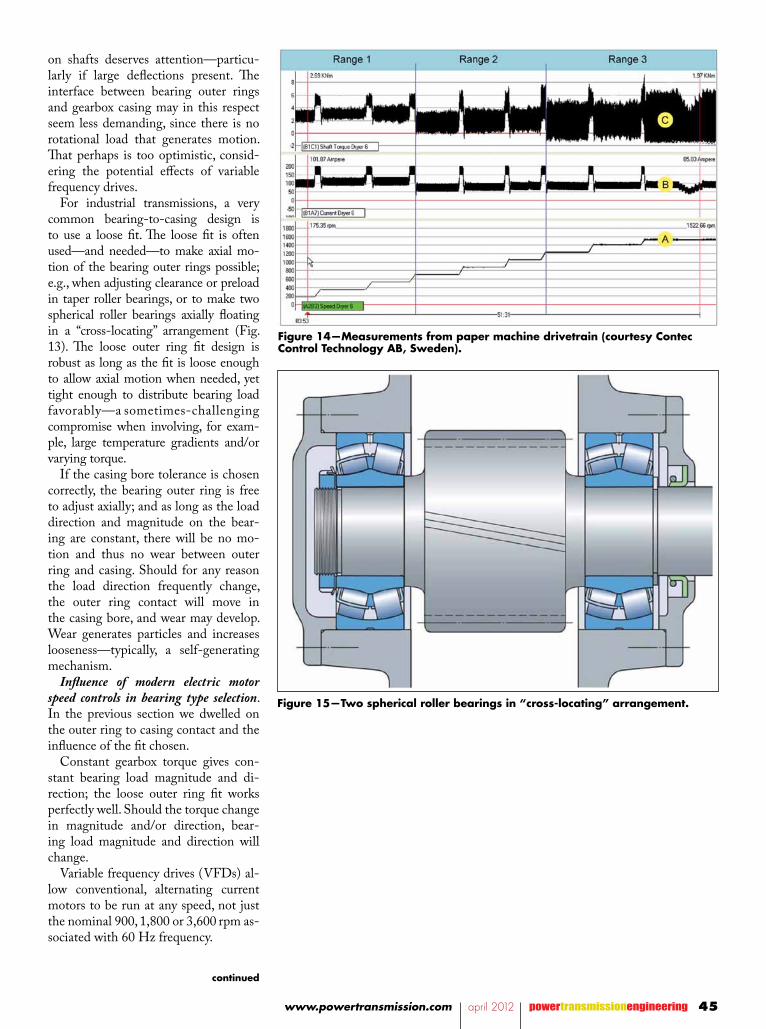
For industrial transmissions, a very common bearing-to-casing design is to use a loose fit. The loose fit is often used—and needed—to make axial mo-tion of the bearing outer rings possible; e.g., when adjusting clearance or preload in taper roller bearings, or to make two spherical roller bearings axially floating in a “cross-locating” arrangement (Fig. 13). The loose outer ring fit design is robust as long as the fit is loose enough to allow axial motion when needed, yet tight enough to distribute bearing load favorably—a sometimes-challenging compromise when involving, for exam-ple, large temperature gradients and/or varying torque.
If the casing bore tolerance is chosen correctly, the bearing outer ring is free to adjust axially; and as long as the load direction and magnitude on the bear-ing are constant, there will be no mo-tion and thus no wear between outer ring and casing. Should for any reason the load direction frequently change, the outer ring contact will move in the casing bore, and wear may develop. Wear generates particles and increases looseness—typically, a self-generating mechanism.
Influence of modern electric motor speed controls in bearing type selection. In the previous section we dwelled on the outer ring to casing contact and the influence of the fit chosen.
Constant gearbox torque gives con-stant bearing load magnitude and di-rection; the loose outer ring fit works perfectly well. Should the torque change in magnitude and/or direction, bear-ing load magnitude and direction will change.
Variable frequency drives (VFDs) al-low conventional, alternating current motors to be run at any speed, not just the nominal 900, 1,800 or 3,600 rpm as-sociated with 60 Hz frequency.
Figure 14—Measurements from paper machine drivetrain (courtesy Contec Control Technology AB, Sweden).
Figure 15—Two spherical roller bearings in “cross-locating” arrangement.
continued
45www.powertransmission.com april 2012 powertransmissionengineering

Many reports on subjects like pulsat-ing torque, torque ripple and short-time torque peaks resulting from VFDs have been written, with the main focus on electric effects like bearing common-mode voltage, currents, voltage spikes, etc. (Ref. 15). To some extent concerns such as broken couplings and twisted shafts have also been reported (Ref. 16). Such extreme examples are fortunately rare. From a transmission bearing per-spective, however, torque variations far less than what are needed to destroy couplings or shafts may generate mo-tion and, consequently, wear between the bearing outer ring and casing.
VFDs are used to drive a machine
with a constant and variable speed, typically including a feedback loop to keep the machine speed constant even if the load changes. VFDs are also normally programmable to smoothly ramp the speed of the drive motor up from, say, standstill to the desired op-erating machine speed. Depending on how the complete drivetrain—motor/coupling/gearbox/drive/shaft/driven machine—behaves in the torsional resonance domain with relation to how the VFD speed control or speed ramp-up behaves, the drivetrain may or may not excite any of its natural (torsional) frequencies. If the speed control loop or the speed ramp-up parameters are set
with, e.g., unfortunate gain, a torsional resonance excitation may be sustained. Typically, one can easily monitor a drivetrain's performance; on the other hand, the gearbox in the middle may in-cur damage that goes unnoticed. A pul-sating torque may (in a system with low damping) develop into reversing torque, in turn reversing shaft, gear and bearing loads.
In such a situation a gearbox designed with loose outer-ring fit seat tolerances will suffer from wear. The wear will generate iron oxide—a mild but pow-erful abrasive agent also contributing to wear—as well as harder components such as gears and bearings. Eventually the gearbox ceases to function due to bad gear mesh and/or worn out bearings.
The measurements in Figure 14 made on a drivetrain for a dryer section of a paper machine illustrate the above be-havior. The measurements were made in an attempt to find the reasons for gear-box noise and limited drive shaft card and joint service life. Three physical pa-rameters were monitored: driving motor speed (1), driving motor current (2) and driven machine torque (3).
The speed was increased following a programmed ramp-up; the motor cur-rent appeared as a range around 100 amps with the expected peaks, when the speed made an increment (i.e., when the machine was accelerated, the current was higher) and the torque delivered to the driven machine behaved similarly to the current—at least within Range 1. After that the torque showed an in-creasing variation (Range 2) and after that (Range 3) the torque progressed from varying to reversing. Naturally, the complete drivetrain rotated continu-ously; it was only the torque that was reversing—not the rotational direction.
Unless the gear and shaft masses are very large, operation under conditions such as those in Range 3 will, for most bearing positions in the gearbox, result in large changes in load magnitude and load direction. Naturally, bearing fatigue life is reduced due to increased mean loads. But the wear associated with a loose outer ring to casing design sub-jected to frequently changing load di-rection will very likely be noticed much sooner than fatigue of a bearing raceway.
Figure 16—Different fixed–floating bearing arrangements.
powertransmissionengineering april 2012 www.powertransmission.com46

The solution to gearbox service life limitations such as worn bearing seats in the casing and the resulting conse-quences is to design for changing load di-rection—i.e., leave the classic loose outer ring to casing fit “cross-location” designs (Fig. 15) in favor of tighter outer ring to casing fitting tolerances. This means that axial expansion of shafts in relation to casing no longer can be managed via axial movement of one or both outer rings, so other solutions are necessary.
Bearing arrangements such as two cy-lindrical roller bearings (for taper roller bearings, a tight outer ring fit makes ax-ial clearance/preload adjustment more challenging) or arrangements of the fixed–floating type are then the right choice.
Fixed–floating arrangements (Fig. 16) can be made in a number of ways. For the examples shown the common factor is that the axial shaft expansion occurs inside one of the radial bearings, not between the outer ring and the hous-ing. In the past, fixed–floating bearing arrangements were limited to so-called “stiff ” bearings (i.e., not self-aligning). But with the introduction of the toroi-dal roller bearing design, self-aligning bearing arrangements are suited to tight outer ring to casing fit fixed–floating bearing arrangements.
Discussion and ConclusionsDespite the existence of advanced
fatigue models for the sizing of bear-ings, the service life of bearings in gear-boxes (and the service life of gearboxes themselves) is a more extensive matter than simply finding a sufficiently large bearing dynamic carrying capacity. Phe-nomena such as poor lubrication and contaminant-initiated surface fatigue are at least as important. New devel-opments in the understanding of sur-face-initiated damage and how to treat material and surfaces to better-resist motion under high contact pressure of-fer significant improvement, but only as they relate to a larger dynamic carrying capacity in the bearings.
Finally, modern material and modern electric drive systems offer new oppor-tunities for industrial gearboxes. But in order to benefit—not suffer—from some of the effects of strong shaft ma-terials and multi-megawatt VFDs, bear-ing interface designs, tolerances and bearing arrangements must be adapted to the new operating conditions.
References1. Morales-Espejel, G.E., A. Gabelli
and E. Ioannides. “Microgeometry Lubrication and Life Ratings of Rolling Bearings,” Proceedings of the Institution of Mechanical Engineers, Part C, Vol. 224, pp. 2610–2626, 2010.
2. Ioannides, E., G. Bergling and A. Gabelli. “An Analytical Formulation for the Life of Rolling Bearings,” Acta Polytechnica Scandinavia, Mechanical Engineering Series, 1999, 137.
3. Gabelli, A., G.E. Morales-Espejel and E. Ioannides. “Particle Damage in Hertzian Contacts and Life Ratings in Rolling Bearings,” Tribolology, Transactions., 2008, 51, pp. 428–445.
4. Lundberg, G. and A. Palmgren. “Dynamic Capacity of Rolling Bearings,” Acta Polytechnica Scandinavia, Mechanical Engineering Series, Royal Swedish Academy of Engineering Sciences, 1947, 1(3).
5. ISO 15243:2004: Rolling Bearings—Damage and Failures: Terms, Characteristics and Causes.
6. SKF. a) General Catalogue: 6000/I EN, 2008; b) Brochure: SKF Oil Injection Method, 2930E; c) Book: SKF Bearings in Electrical Machines, 2124E; d) TI Leaflet: Axle Boxes for Wheel Shafts in Railway Vehicles, TI 6810.
7. Oila, A. and S.J. Bull. “Assessment of the Factors Influencing Micropitting in Rolling/Sliding Contacts,” Wear, Vol. 258, pp. 1510–1524, 2005.
8. Brandão, J.A., J.H.O. Seabra and J. Castro. “Surface-Initiated Tooth Flank
Damage–Part I: Numerical Model,” Wear, Vol. 268, pp. 1–12, 2010.
9. Brandão, J.A., J.H.O Seabra and J. Castro. “Surface-Initiated Tooth Flank Damage–Part II: Prediction of Micropitting Initiation and Mass Loss,” Wear, Vol. 268, pp. 13–22, 2010.
10. Lainé, E. and A.V. Olver. “The Effect of Anti-Wear Additives on Fatigue Damage,” Extended Abstract, 62nd STLE Annual Meeting, 2007.
11. Lainé, E., A.V. Olver and T.A. Beveridge. “Effect of Lubricants on Micropitting and Wear,” Tribology International, 41, pp. 1049–1055, 2008.
12. Lainé, E., A.V. Olver, M.F. Lekstrom, A. Shollock, T.A. Beveridge and D.Y. Hua. “The Effect of a Friction Modifier Additive on Micropitting,” Tribology, Transactions, 52, pp. 526–533, 2009.
13. Kim, T.H. and A.V. Olver. “Stress History in Rolling–Sliding Contact of Rough Surfaces,” Tribology International, 12, pp. 727–736, 1998.
14. Stephens, R.I., A. Fatemi and R.R. Stephens. Metal Fatigue in Engineering, Second Edition, John Wiley and Sons Ltd, 2000.
15. Song-Manguelle, J., S. Schröder, T. Geyer, G. Ekemb and J.M. Nyobe-Yome. “Prediction of Mechanical Shaft Failures Due to Pulsating Torques of Variable Frequency Drives,” IEEE Transactions on Industry Applications, Sept.– Oct. 2010, Volume 46 Issue 5, pp. 1979–1988.
16. Meckel, C. “Mechanical Damage of a Sub-Synchronous Cascade Drive Due to Torsional Resonance,” Cement Industry Technical Conf., IEEE IAS/PCA, pp. 133–150, 2001.
Hans Wendeberg graduated in 1981 with a Masters in Mechanical Engineering at Chalmers University of Technology. He has since worked at SKF, Sweden. Wendeberg’s work at SKF has focused on product development and customer-focused application engineering in a number of industries, particularly those involving custom, high-power-density transmissions. He is currently manager of application development, responsible for the development of performance-related application rules for self-aligning bearings, training and troubleshooting.
47www.powertransmission.com april 2012 powertransmissionengineering


![History ICSM4/M16Optional accessories[1] Optional accessories[2] ... Split gearbox brings many advantages to airsoft players. The split gearbox is modular design which can simulate](https://static.fdocuments.in/doc/165x107/5f92441f9c07a372be591193/history-icsm4-optional-accessories1-optional-accessories2-split-gearbox.jpg)


