Gearbox and Overdrive - mgb-stuff.org.uk · gearbox casing, not the whole gearbox moving around,...
23
Contents Index So you think you want an MGB or V8? Body Brakes Clutch Cooling Electrics Engine Fuel Gearbox Heater Ignition Propshaft Rear axle Steering and Suspension Wheels and Tyres Miscellaneous Downloadable PDFs The sectioned MGB at the British Motor Museum, Gaydon Gearbox and Overdrive Last updated 17-Dec-2019 If you find the information here useful, you may like to make a small contribution to help offset the costs of providing it. Thank you. Auto Kickdown Cable Breather Drive Flange Gear Lever Gearbox Removal How It Works Interlocking Arm Assembly Internals Lubricants Mounts and crossmember Oil Change Overdrive: D and LH Type Differences Overdrive Electrics Overdrive Fusing Overdrive 'Pulsing' Overdrive Replacement Overdrive Sequencer Relay Overdrive: How many were there? Rear Seal Reversing Light Switch Speedometers Torque Values Links Auto Kickdown Cable Added December 2008 André Wilding contacted me to ask if I could offer any advice in changing the kick-down cable, as the gearbox end seems to be concealed inside the gearbox, and where it goes in is concealed by the tunnel! I have no personal experience of changing one of these cables, but from the diagrams and descriptions in the workshop manual it appeared that the pan might have to be removed, which would mean draining the fluid first of course. Using that bit of information André took the plunge, and subsequently wrote back to me with the following: "You have to drop the pan because the cable end fixes into a cam in the gearbox and there is no other way to get to it. "The 'cut-out' modification in the transmission tunnel is essential for getting to the screw in part of the cable where it goes into the gear box. Without it I think you would have to take out the gearbox etc. Even with it, it is a pig to Page 1 of 46 20 December 2019 get at and takes ages to screw in tight! Also, the hole is handy for getting at the reverse switch if something happens to it. "Apart from that - it's an easy job!" Breather 4-synch gearboxes of both types have a breather at the front left of the gearlever remote unit. 3-synch non-OD have one top centre of the tube on the back of the bell-housing which carries the gear change mechanism. However 3-synch OD don't seem to have the plastic breather, just a horizontal drilling at the right front of the gearlever remote unit. Drive Flange March 2017 4-cylinder: The propshaft bolts cannot be removed from the drive flange until the flange is removed from the output shaft - on LH-type overdrives at least (see below). Bolts are 5/16" UNF - standard hex head on Mk1, but on the Mk2 they are specials with a domed, round head having a flat on one side. The flat locks against the side of the flange to hold the bolt while the nut is tightened or loosened, meaning only one spanner is needed. V8: The V8 drive flange is larger, and that together with a flat on the OD casing allows the bolts to be removed with the flange still fitted. The V8 bolts are also larger at 3/8" UNF but otherwise have a similar domed, round head with a flat on one side. All: Before I realised I could remove the V8s bolts with the flange in position I thought I'd have to remove the flange. A pal made his own tool when changing the output shaft oil seal, but I knew that would not fit the larger V8 flange, so would have to come up with something for myself. I then suddenly realised I had made a tool to hold the cam-shafts and gears still when replacing the cam belts on the ZS, which should do the job. Made from B&Q flat steel bar (if their hardware is good enough for brain surgery it's good enough for me ...). It is a pivoting forked tool with bolts in the ends of the forks to fit holes in the cam gears, but with those bolts removed the holes are a perfect fit for two of the 3/8" bolts in the flange, to leave plenty of space for a socket on the nut. The long arm will rest against the edge of the tunnel (with protection) on the offside for loosening, and the near-side for retightening. The beauty of this tool is that it is universal, i.e. will fit any size of flange! Page 2 of 46 20 December 2019
Transcript of Gearbox and Overdrive - mgb-stuff.org.uk · gearbox casing, not the whole gearbox moving around,...

Contents Index So you think you want an MGB or V8? Body Brakes Clutch Cooling Electrics Engine Fuel Gearbox Heater Ignition Propshaft Rear axle
Steering and Suspension Wheels and Tyres Miscellaneous Downloadable PDFs The sectioned MGB at the British Motor Museum, Gaydon
Gearbox and Overdrive
Last updated 17-Dec-2019
If you find the information here useful, you may like to make a small contribution
to help offset the costs of providing it. Thank you.
Auto Kickdown Cable Breather Drive Flange Gear Lever Gearbox Removal How It Works Interlocking Arm Assembly Internals Lubricants
Mounts and crossmember Oil Change Overdrive: D and LH Type Differences Overdrive Electrics Overdrive Fusing Overdrive 'Pulsing' Overdrive Replacement Overdrive Sequencer Relay
Overdrive: How many were there? Rear Seal Reversing Light Switch Speedometers Torque Values Links
Auto Kickdown Cable Added December 2008
André Wilding contacted me to ask if I could offer any advice in changing the kick-down cable, as the gearbox end seems to be concealed inside the gearbox, and where it goes in is concealed by the tunnel! I have no personal experience of changing one of these cables, but from the diagrams and descriptions in the workshop manual it appeared that the pan might have to be removed, which would mean draining the fluid first of course. Using that bit of information André took the plunge, and subsequently wrote back to me with the following:
"You have to drop the pan because the cable end fixes into a cam in the gearbox and there is no other way to get to it.
"The 'cut-out' modification in the transmission tunnel is essential for getting to the screw in part of the cable where it goes into the gear box. Without it I think you would have to take out the gearbox etc. Even with it, it is a pig to
Page 1 of 46
20 December 2019
get at and takes ages to screw in tight! Also, the hole is handy for getting at the reverse switch if something happens to it.
"Apart from that - it's an easy job!"
Breather
4-synch gearboxes of both types have a breather at the front left of the gearlever remote unit. 3-synch non-OD have one top centre of the tube on the back of the bell-housing which carries the gear change mechanism. However 3-synch OD don't seem
to have the plastic breather, just a horizontal drilling at the right front of the gearlever remote unit.
Drive Flange March 2017
4-cylinder: The propshaft bolts cannot be removed from the drive flange until the flange is removed from the output shaft - on LH-type overdrives at least (see below). Bolts are 5/16" UNF - standard hex head on Mk1, but on the Mk2 they are specials with a domed, round head having a flat on one side. The flat locks against the side of the flange to hold the bolt while the nut is tightened or loosened, meaning only one spanner is needed.
V8:
The V8 drive flange is larger, and that together with a flat on the OD casing allows the bolts to be removed with the flange still fitted. The V8 bolts are also larger at 3/8" UNF but otherwise have a similar domed, round head with a flat on one side.
All:
Before I realised I could remove the V8s bolts with the flange in position I thought I'd have to remove the flange. A pal made his own tool when changing the output shaft oil seal, but I knew that would not fit the larger V8 flange, so would have to come up with something for myself. I then suddenly realised I
had made a tool to hold the cam-shafts and gears still when replacing the cam belts on the ZS, which should do the job. Made from B&Q flat steel bar (if their hardware is good enough for brain surgery it's good enough for me ...). It is a pivoting forked tool with bolts in the ends of the forks to fit holes in the cam gears, but with those bolts removed the holes are a perfect fit for two of the 3/8" bolts in the flange, to leave plenty of space for a socket on the nut. The long arm will rest against the edge of the tunnel (with protection) on the offside for loosening, and the near-side for retightening. The beauty of this tool is that it is universal, i.e. will fit any size of flange!
Page 2 of 46
20 December 2019

Gear Lever May 2017
Gaiter Anti-rattle bushes
Gaiter: Originally a ribbed rubber tube (3-synch) or cone (4-synch) coming less than half-way up the chromed lever. In 1972 with the advent of the centre arm-rest and cubby it became taller covering the whole length of the (painted) lever to the underside of the knob, comprising a ribbed rubber cone inside a vinyl outer, which is stapled to the flange at the bottom of the rubber. All were retained to the tunnel with a chrome trim-ring and four screws - self tappers on 3-synch, Pozidrive on 4-synch with the front screw being shorter than the others. It's said that the front screw is shorter so it clears the top of the gearbox remote control casting as the gearbox moves around, although when I replaced Bee's 30 years ago I fitted four long ones and it's not caused a problem. As the front screw goes into a small removable panel sitting on top of the tunnel and its heat insulation, the nut for the front screw is closer to the trim ring than the others, so the screw can be shorter for that reason as well.
After Vee's rebuilt engine and (unmolested gearbox) went back in 2017 OD has tended to disengage on the overrun, re-engaging when the accelerator was opened again, which it never did before. Suspecting the switch I took it out and sure enough electrical continuity was erratic as the plunger was operated. Fitted a new switch ... and it was just the same. The problem with the V8 is that OD is only available in 4th gear, and only starts closing as the lever is pulled back, whereas the 4-cylinder with it on 3rd and 4th starts closing as soon as the lever is moved across the gate towards the 3/4 plane. This means there is less travel of the mechanism inside the gearbox to operate the switch, so positioning is more critical.
As the switch is shimmed I started playing around with those - replacing the original 50 thou copper original with variously 45, 42 and 40 thou built up from a 40 thou fibre washer plus various front wheel bearing shims (which happen to be a very good fit). 40 thou ended up with the switch operated all the time i.e. in any gear which is obviously no good, 45 was the same as 50, but 42 seemed to work. However that is only 2 thou away from being on all the time, so a bit close for comfort. Along the way I discovered that if the lever were pulled back when it disengaged it would go back in, and with the thinner shims if I pulled it across the gate towards me OD would engage, even in reverse and 3rd - not right, but less of an issue than the 2 thou tolerance between working correctly and being on all the time.
Then in slowing down and speeding up traffic on the M6 coming back from the Lake District I discovered that when it did disengage - which wasn't every time, the lever would move forwards about 1/4", and if I pulled it back it re-engaged, as it did when I opened the throttle again. This is lever movement relative to the
Page 3 of 46
20 December 2019
gearbox casing, not the whole gearbox moving around, which made me wonder if it was on the verge of jumping out of gear as well, i.e. worn synchro detents!
Talking to Roger Parker he suggested removing the gaiter, which I had already wondered about. But first I put it into each gear in turn trying to feel as best as possible just how much effort was required, and noticed that 4th seemed to need more than the other gears. Comparing it with Bee (handy having two) Bee did need slightly less effort, but it needed slightly more effort than Vee to take it out of gear again i.e. Bee's detents seemed stronger than Vee's. And in fact Bee has always tended to 'hang up' coming out of 4th occasionally, needing a second harder push. But that's another story.
Next step with Vee was to remove the trim-ring from the gaiter ... and I was absolutely gob-smacked at how much easier the lever was to move in all gears, but especially 4th - 'light as a feather' springs to mind. Also the front left corner of the gaiter tipped right up in the air when 4th gear was selected, and
manually trying to push it down again and pull the screw holes into line with it in 4th was almost impossible. So the gaiter is putting considerable force on the lever especially in 4th gear - so much for the age-old exhortation not to drive with your hand on the lever as it wears the linkages! The problem is that although the rubber is malleable, having the vinyl over the top means that when the lever is in (especially) 4th there is a bigger distance from just under the knob to the trim ring at front left, than when in neutral. The vinyl has no ribs and can't stretch, so it has to pull itself down the lever shaft, which means it has to push the rubber down as well. This is quite a snug fit on the lever, so doesn't slide easily. I thought about reducing the height of the rubber gaiter to something like the earlier ones with a couple of ties, but opted for some Vaseline on the shaft and inside the hole in the rubber gaiter. The result is a far lighter gear shift on Vee, especially in 4th, the top of the gaiter sliding down the shaft at least an inch. Something else Roger mentioned was that he has had the same problem when putting a 5-speed into an MGB, but put that down to the fact it was non-standard. On Vee, over a run of a dozen miles or so, accelerating and decelerating in 4th, not only did OD not disengage, but the tendency of the lever to ease forwards in 4th is very much reduced. Still there slightly, but when it does happen it's not immediately I decelerate but a few seconds after, and not as far.
Something else I noticed comparing Vee with Bee with the gaiters off is that looking down on the gear lever, the tail of Vee's gearbox is noticeably closer to the driver than Bee's. Logic implies the middle of the H-gate i.e. the 1/2 plane should
be central in the tunnel so the amount of movement of the gaiter is approximately the same in each gear, and if the knob needs to be moved relative to the driver then that is achieved by cranking the lever, as was done significantly on the 3-synch, only slightly on the painted 4-synch, and possibly not at all on the chrome 4-synch. Could be tolerance in clearances in the bolts and studs that form part of the gearbox mounting, I tried shifting the crossmember across but it made no difference. I also adjusted the engine steady bar to pull the top of the engine across to the nearside, wondering if that would pull the gearbox across a bit, but
Page 4 of 46
20 December 2019

again not. That leaves the way the gearbox rubbers are attached to the gearbox and the crossmember, but short of a full hoist that's not really feasible to do anything about. I'm pondering putting a rubber bush between the drivers side of the tunnel and the tail of the gearbox! But that may generate noise in the cabin. For the moment gearbox positioning will have to stay as it is.
I'm leaving the switch with 42 thou for the moment, but because of my concerns of it being only 2 thou away from being on all the time, I moved the (PO-fitted) OD tell-tale from being on the manual switch to being on the gearbox switch, so I can see when OD is truly engaged, and not just showing that the manual switch is on, and try to remember to look at that when not in an OD gear, especially when about to select reverse. But next day I decided to go one step further and wire up a relay with a normally closed contact to the reverse light circuit, to give a second break in the OD circuit whenever reverse is selected. I'll still try and remember to look at the tell-tale when in other forward gears to check the positioning of the OD switch, give it some miles, and if it is no longer disengaging on the overrun will start upping the shims again.
But I'm also pondering mounting a micro-switch with a long flexible operating lever, on a bracket, screwed to the top of two of the lever retaining screws (drilling and tapping the heads), and using that instead of the original gearbox switch. With the switch mounted beside the lever, and angled appropriately, there should be loads of travel on the switch lever to ensure it is fully operated even when the lever moves back and fore slightly, but fully off when it is moved forward to the neutral plane.
Anti-rattle bushes: Two of these (22H 15) are fitted - one at the bottom of the cabin lever and another at the end of the remote control shaft where it connects to the gearbox shift rods. If either of these bushes is missing the cabin lever becomes sloppy and will rattle about. It was only because my roadster has both that I realised when I got the V8 that at least one was missing. With the bushes, when the gearbox is in any gear, there should be virtually no free play in the lever at all. If you have free play in a gear, then the chances are that one or both are missing. The one on the lever is easy to deal with, the one for the shift-rods less so - with the 4-synch tunnel the gearbox would have to be removed, although you may get access on the 3-synch by removing the larger access panel. Fortunately only the one on the cabin lever was missing.
For the one on the lever remove the four chrome screws and trim ring round the cabin lever, and lift up the vinyl and rubber gaiters. 3-synch: There is a circlip that retains a cover in the remote control tower, and under the tower is a spring pressing down on the large ball on the gear lever. 4-synch: Remove the
three shouldered screws (22B525) and Thackery washers (AJD7731, oddly on both my cars one of the washers was a standard spring washer). All: Lift the lever up and out.
Page 5 of 46
20 December 2019
There seem to be two possible ways to fit the bush - in the socket in the remote control shaft, or on the ball at the end of the lever. The first method will result in the bush being pushed straight out of the bottom of the socket when you try to push the
lever into it. The second method starts off well enough as there is a split up the side of the bush, and it goes on the ball-end of the cabin lever easily. However when you then try to push the lever back into the remote control shaft socket, it either won't go, or the bush will be pushed further up the shaft! That may be the case with a new bush, if reinstalling with an old one just tapping the end of the lever with a mallet may be all that is required.
The bush has a chamfer at the top which is presumably supposed to make this second method easier, but it is at far too abrupt an angle to help. Place the bush chamfer end down, and use a craft knife to make a more gradual chamfer around the periphery, and it should then go in.
Both 3-synch and 4-synch have two locating pins screwed through opposite sides of the casing to protrude into the large socket, which engage with slots in the large ball on the lever. This allows the lever to move sideways across the gate and fore and aft into the gears, but prevents it rotating.
4-synch remote control towers have a sprung plunger going through the casing and pressing against the large ball on the lever. The Parts catalogue describes these as 'lever-damping' components, but as they have a sprung plate pressing down on top of the ball I don't know why it needs this additional damping.
3-synch OD have a 'plunger' at the gear-lever end of the remote control tower, but no indication as to what it is for. They have a single large spring pressing down on the large ball, which again would provide adequate damping, one would have thought.
Because the levers have two slots it's probably possible to fit them either way round. The 3-synch lever has a double-crank rearwards so it's obvious which way round it goes. Clausager says that the 4-synch lever is completely straight, but mine have a slight kink low down. It's less obvious which way round
it goes, but it angles the lever rearwards.
The lever seating plate has three holes so conceivably could go in any of three orientations. However rather than a hole for the lever it has a slot, and this is positioned fore and aft, meaning it can only fit one way. In the other two positions the slot would be diagonal. It also has a raised portion on one side of the slot,
which goes on the left.
In 1977 all cars changed to having a slider switch in the gear knob, and another sub-harness down the gear lever connecting
Page 6 of 46
20 December 2019

to the gearbox harness. There have been cases of this harness chafing and shorting out with the continual movement of the
gear lever. As the OD is unfused this can seriously damage the other harnesses so fusing of the OD circuit is strongly advised.
This type of gear lever has a significantly thickened section just above the retaining plate, so the plate is slotted to enable the two to be parted and reunited.
Gearbox Removal December 2019
The most obvious way is attached to the engine through the engine bay, but that is beyond me with access limited by a folding hoist and a single-width garage, albeit double-length. I've had no problem removing the 4-cylinder engine, and I was pretty sure I'd be doing the same thing if I needed to extract the gearbox, and remove that from under the car. When Vee's gearbox started whining about a year after getting back on the road after an engine
rebuild - very annoying - I didn't want to send her away after the nightmare last time, but knew removing the V8 engine is nothing like as simple as the 4-cylinder for a variety of reasons. But one of my contacts put me onto a chap who knows these gearboxes, and has a V8, and he told me how it could be done.
If you are going to work on the gearbox or OD and need to drain the oil do the main draining before removal, then once out stand the gearbox on its bell-housing end - on blocks of wood not the end of the 1st motion shaft, and leave it like that for a couple of hours at least with the drain plug back in. What is in the OD will drain into the main casing, then lay the gearbox down, remove the main drain plug, and be prepared for almost another pint.
How it works October 2017
Page 7 of 46
20 December 2019
Another excellent explanation from Chrysler in 1936 of how a gearbox works, including synchromesh. One thing that puzzled me for a while is reverse gear at 6 minutes and 50 seconds in. It isn't clear that the reverse idler gear with two cogs is positioned in front of the 'counter' or lay shaft, at first glance it seems to be the same shaft with an extra gear. Thus the countershaft turns the reverse idler gear all the time, and the large sliding gear on the output shaft moves into engagement with the gear on the countershaft for first gear, and with the other end of the reverse idler gear for reverse gear.
It's easier to see on this drawing from
'How Stuff Works' - all the forward gears connect directly with the lay shaft, but reverse gear connects via the reverse idler gear which ... reverses the direction of rotation.
Interlocking Arm Assembly Added July 2010
Stephen Stringer wrote to me while changing his 3-synch non-OD to OD. He had to obtain parts to build the OD gearbox up but couldn't find an Interlocking Arm Assembly. The 3-synch non-OD item is very different, the 4-synch looks similar and although it drops in the gears wouldn't select. As they selected with it not fitted
Page 8 of 46
20 December 2019
Stephen was wondering whether he could leave it out, or if I could point him at a source for one. I don't know exactly what this part does but the word 'interlock' makes me think it is something to do with preventing two gears being engaged at once under certain conditions, which would be catastrophic. The part also seems to be NLA. Unusually the 'official' Workshop Manual and Parts Catalogues weren't that helpful as they didn't show both 3-synch and 4-synch for comparison (and in any case are only drawings i.e. only representative) and Haynes was the best source with a couple of photos that showed the part. From these I reckoned that a 4-synch could be made to fit, and Stephen subsequently reported that this was indeed the case. He says: "It's a simple mod, cut the mounting flange along the bend, move the cut off part back 4mm and reweld, that's it."
Internals Added January 2015
Michael Beswick gets hold of a spare gearbox and dismantles it for interest and information.
Lubricants Added March 2014
The most important thing to be aware of is the correct oil to use, as the V8 is different to the 4-cylinder, and the V8 axle is different to its gearbox:
4-Cylinder V8 Gear oil vs axle oil
4-Cylinder: The 4-cylinder gearbox and overdrive is straight-forward as it takes engine oil of the same grade as for the engine e.g. 20W/50. However this BL Technical Service Bulletin dated April 1975 says SAE 90 gear oil supersedes engine oil, although elsewhere there are unverified statements that it was subsequently rescinded. This British Automotive article (scroll down to 'Transmission oil') also states that rubber bumper MGBs used gear oil, although references to 'brass synchro rings' and 'non-syncromesh' are variously confusing and incorrect as brass syncro rings were only in the 3-synch - not 'non synchromesh' - gearboxes that predate this change. But Driver's Handbooks for RHD rubber bumper cars of two issues - up to 76 and 77 and later - make no mention of the change. If the 'GAJ-3/19/75' at the bottom of the Technical Service Bulletin is a date, then it would be an American document as it is in the month/day/year format they use and not the day/month/year format the UK uses. That tends to confirm the change was for North America only, although why, and how, when RHD and LHD were built at the same location can only be guessed at.
The 3-synch gearbox takes 4.5 Imperial pints, 2.56 litres, 5.6 US pints and the 3-synch gearbox plus OD takes 5.33 Imperial pints, 3.36 litres, 6 US pints. The 4-synch gearbox takes 5.25 Imperial pints, 3 litres, 7 US pints and the 4-synch gearbox and OD takes 6 Imperial pints, 3.4 litres, 7 US pints. Note these are for
Page 9 of 46
20 December 2019
clean and dry gearboxes, a drain and refill can be expected to take a little less than that as some oil is bound to be left behind, particularly with an overdrive.
V8: The V8 gearbox is different in that it takes gear oil instead of engine oil, to cope with the higher torque - 6 Imperial pints, 3.4 Litres. Some claim gear oil makes the V8 gear change very heavy in cold weather, but I used mine for several years in all weathers including several periods of well below freezing and didn't have any difficulties. The confusion may come from gear oil typically being SAE 80 or 90 whereas engine oil is typically SAE 20W/50, and some people describing those numbers as 'weights' which implies viscosity. They aren't, they are just arbitrary number ranges for engine oils and gear oils that don't overlap with each other. The reasoning behind this non-overlapping is to avoid confusion and people using engine oil where they should be using gear oil or differential oil which would result in rapid wear. The opposite may be equally damaging as the additives in gear and differential oils may harm the soft metals of the bearings. However it is equally important to know the difference between gear oil and differential oil, of which more later.
The actual viscosity of SAE80 gear oil is 7cSt, which falls between the viscosity of 20W engine oil at 5.6cSt and 25W at 9.3cSt. SAE90 gear oil is 13.5cSt which falls between SAE40 engine oil at 12.5cSt and SAE50 at 16.3cSt. So you can see that SAE90 gear oil is in exactly the same viscosity range as 20W/50 engine oil.
Gear oils vs axle oils:
To add to the confusion it is usual these days for manufacturers to refer to gear and axle oils by a GL number from 1 to 6. Usually GL4 and GL5 are used for passenger cars, and in most cases GL4 will be used for gearboxes and GL5 for axles, although in some modern cars GL5 is specified for gearboxes, perhaps where they contain the diff as well. GL5
oils are intended for hypoid-type applications most commonly found in axles, but a GL4 oil may be specified for axles that don't have a hypoid action. Some GL4 oils may be suitable for the rear axle, check they have statements to the effect that they are 'extreme pressure' or 'mild extreme pressure' and are suitable for hypoid axles. GL5 oils have additional anti-wear additives that can be harmful to some of the components in a gearbox designed to take GL4. Gear and axle additives are designed to coat the metal surfaces, and are 'sacrificial' in that it is the oil coating that is stripped away (replaced when the teeth go back into the oil bath or are otherwise sprayed) during use rather than the metal being worn away. But GL5 additives stick more tightly to the metal than GL4, and if used in GL4 gearboxes, when the additive is stripped away from softer metals it sticks so well that it actually takes a microscopic layer of metal away with it, even though there has been no metal to metal contact. This gives rise to another misconception of GL5 axle oils when used in a GL4 gearbox - that they in some way 'attack' the softer metals. But it's not a chemical reaction that dissolves the metal merely by being in contact with it, but the stripping action in use as described.
Both V8 gearbox and rear axle oils are typically based on SAE90 for temperate climates, but with the different anti-wear characteristics as described above, and
Page 10 of 46
20 December 2019

different manufacturers describe their products in different ways. For example the Workshop Manual specifies Castrol Hypoy for the gearbox but Castrol Hypoy B90 for the axle i.e. 'Hypoy' in both cases. Esso equivalents are GP90 and GX90, but Mobil specifies GX90 for the gearbox and HD90 for the axle, so you can't rely on the letters to tell you whether they are for gearbox or axle. At the time of writing Castrol products are labelled a bit more clearly, as 'EP-90 Manual Transmission Fluid' and 'GL4' for the V8 gearbox and 'EPX 80W-90 Differential Oil' and 'GL5' for the axle in both V8 and 4-cylinder cars. Additional confirmation of application is that the label includes a drawing of either a gear change or a rear axle respectively.
Corrected May 2016: The final differentiation between gear and axle oils is one of smell - GL5 oils i.e. for MGB axles have a very distinct, sulphurous, smell whereas GL4 oil for the V8 gearbox is very similar to engine oil. Both GL4 gear and GL5 axle oils have the distinctive sulphurous smell, with GL5 perhaps a little more than GL4. It's engine oil as used in 4-cylinder gearboxes that does not have this smell.
Mounts and crossmember Added January 2011
Restraint Rods
Michael Beswick tackles replacement of the gearbox mounts on his 69/70 and has documented in great detail the trials and tribulations at getting at all the nuts and bolts, and making the oft-discussed modification to the crossmember to make the job easier.
December 2019: With Vee's engine and gearbox out as part of work of both I had the opportunity to investigate this aspect in the 'open air' so to speak. It's said that there are at least 16 ways of installing the crossmember, and maybe 32! However careful consideration can eliminate most if not all of these, and the following relates
to 4-synch OD both for 4-cylinder and V8:
The first is which way round the crossmember goes - where there is a dip on one face that faces forwards - 2 ways.
1.
Next the upper yoke that holds the central pin and is attached to the gearbox under the rubber mounts can go either way round. The correct way has the 'flat' side of the yoke facing forwards - 4 ways.
2.
Next the yoke under the pin can twist on the pin to go either way round, and as the welded nuts in the lower part are offset that changes the fore and aft position of the nuts relative to everything else. The correct way is with the nuts behind the pin - 8 ways.
3.
Finally there are two holes each side in the angled brackets on the crossmember for the mount studs to fit into, which changes the fore and aft position of the crossmember relative to the gearbox. On 4-sync cars with OD the correct position is the front-most hole - 16 ways. It's said that the
4.
Page 11 of 46
20 December 2019
rear holes are for non-OD but that can't be right as the main gearbox casing is the same both with and without. Did I say 'finally'? Another 'twist' is that some replacement rubber mounts instead of being rectangular are 'Z'-shaped, and depending on which way up they are fitted they can be in either shear (bad) or compression (good). But that is obvious from ... observation, and increases the possibilities to 32!
5.
Testing the various options for 2, 3 and 4 showed that the only way that everything lined up was when things were assembled as described, and the upshot is that the mounts end up centrally on the crossmember, with the nuts on the lower yoke lining up with the holes in the crossmember.
That still leaves two sets of tapped holes in the chassis rails to mount the crossmember, and that is determined once the engine has been fitted to its mounts. That is complicated on the V8 by the mounting plates being handed, but capable of being installed on either side. When on the wrong sides the engine is about 1/2" forward of where it should be, and the gearbox crossmember is between two sets of chassis rail holes. When the V8 came to me it was like that and I found the crossmember had been fitted in one pair of holes one side and another pair on the other side! Swapping those plates over with everything in-situ was a real challenge. Amusingly, shortly after that the Classic Car Show at the NEC featured the first re-shell of a V8 ... and they had the plates on the wrong sides.
The first time I refitted the crossmember was with the mounts on the gearbox, the gearbox back in the car, and the car on a full-height ramp, so getting the crossmember back on the mount studs was the next challenge. Some have slotted the crossmember holes but mine aren't. Slackening the mount to gearbox bolts made it easier, but then retightening the mount to gearbox bolts with the crossmember on was not possible for a reason I can't recall. In the end I found that with one side hooked over its stud, the other side popped in when given a hearty upwards shove of the crossmember. Of course it went in the wrong hole, but a firm pull downwards got it off again, and another shove got the stud in the right hole. The next challenge was to get the lock-washers and nuts on the mount studs, for which some have drilled holes in the bottom of the crossmember to take a socket extension at the appropriate angle, fitting the socket to the end afterwards. But I found that with the original rubbers it's not difficult to twist the crossmember first one way then the other, and use an offset ring-spanner which allowed me to tighten them half a flat at a time. Potentially time-consuming and patience-testing, but if you have new mounts/nuts or thread-chase old ones you should be able to get them finger tight first, which should only need a few operations of the spanner. Of course getting old nuts off may be more challenging. I was warned not to replace the rubber mounts unless I needed to, as new ones are much harder than old, and presumably it's much harder to get the stud in the crossmember, as well as tighten the nuts. Having said that one would expect the 'Z' mounts to be more compliant than rectangular. All this was made easier by standing under the car on a full-height ramp, maybe not so easy with the car on low-level ramps/axle stands. This was all for the V8 of course, other gearboxes may vary.
Page 12 of 46
20 December 2019
Restraint Rods: See also Engine Mounts and the section on restraint brackets there.
Mk 1 roadsters had a crossmember with welded nuts at the rear for a restraint rod bracket. A short rod passed through the crossmember and brackets and was retained by a nut. The front of the rod has a 'U'-bracket that goes around a protrusion on the bottom of the gearbox casting close below the speedo cable, and
a special pin goes through the bracket and protrusion with rubber bushes between them.
Mk 1 GTs and initially all Mk2 cars don't appear to have the restraint rod, until 1974.
In Feb 74 (still chrome bumper) a new restraint rod was added to North American cars. This used a welded bracket on the front face of the crossmember, and a longer rod going all the way to a bracket that attaches to the two bottom bolts that secure the bell-housing to the engine. Other markets got this arrangement at the start of rubber
bumpers.
The V8 never had a restraint rod.
And in case you wondered what the crossmember bolted up to - a tapped plate in a cage, so it can move around to accommodate some dimensional differences.
Oil Change
For what oil to use see Lubrication.
Take the car for a run of 10 miles or so to warm things up and allow the old oil to run out a little easier, especially the gear oil in the V8. Make sure you can remove the filler/level plug or dipstick before draining the oil. You can live with not changing the oil for a bit while you ponder how to shift it, but not if you have already drained the oil and can't refill it. I had the front of the car up on ramps and the rear on axle stands so I could do both gearbox and rear axle together, and the car was relatively level making refilling with the correct quantity easier.
The drain plugs (I did both cars) came undone easy enough, although I found a 3/4" spanner and socket were just a bit too big for the roadster (fine for the V8) so used an 18mm socket instead, and left that to drain while I got on with refilling the diff. The drain plug on both the roadster and V8 are hollowed-
out and although at first it didn't look like there were any bits in the hollow, when I stuck a screwdriver in there I did get some bits out. The largest was about 1mm
Page 13 of 46
20 December 2019
in size, the rest much less than that, I suppose it is inevitable in a manual gearbox but I'd rather not have seen it.
When the dripping had slowed I replaced the drain plug and started on the OD sump/filter. The bolts came undone easily, slackening each bit by bit like head bolts/nuts to avoid the chance of warping. Free the sump with at least two of the bolts on opposite sides or ends still loosely fitted so it doesn't fall
away all at once. I had to use a bit of gentle leverage to get the sump parted from the OD body, there is a handy tab on the sump adjacent to the large hex plug for the relief valve expressly for this purpose, it seems. Be ready for more oil to drain out once you have broken the sump seal, quite a bit more comes out here, I left that to drain rather than try getting the sump completely off at that point and fill my sleeves with oil. With the sump off the V8 there was a slight tear in the gasket/filter across the middle bar so I decided to replace it, I had bought one at Stoneleigh last month. The old one took quite a bit of scraping to get off the sump, in hindsight it would probably have been OK to put back as the outer ring was fine. The filter and sump were as clean as a whistle, but got a wash in petrol anyway. The roadster sump came off without any tearing of the gasket, and I decided to leave it stuck to the sump and not clean underneath as any bits should have been on top of the screen. The little specks in this photo are globules of oil or petrol, not bits as I first thought. Touching the screen made some vanish and other appear. I did pour some petrol into the sump through the screen, gave it a good swill and poured it out again, hopefully that should have washed out any fine sludge, it looked clean enough in there from peering through the screen.
The hex plug for the relief valves also came free easily, a little more oil draining out. Be careful not to lose the little O-ring between it and the valve or any of the other bits inside. Whereas on the roadster it was in a groove in the end of the hex plug and didn't come free in washing, on the V8 as I recall
it was loose on top of the hex plug i.e. there was no groove. Careful teasing with a pair of long-nosed pliers got the cylindrical filter out together with the valve assembly. Quite a few bits involved here (13 on the roadster!) so be careful to note what order you find them in and not to lose any.
Whereas the V8 was similar to the drawing in the Workshop Manual the roadster seemed a bit different having a very coarse screen round the upper part of the valve which isn't shown in the drawing, and a large spring above the valve plunger which is shown much smaller in the drawing. I didn't
find any of the 'valve ball, valve spring or low pressure valve plug' on either car. The larger O-ring should be in the groove in the relief valve body so shouldn't come free. The roadster had three shims between the valve plunger and the spring (not shown in the manuals), presumably to set the hydraulic pressure, I didn't find any on the V8.
While you are away from the car put a clean empty container under the OD to catch any bits (e.g. the 'valve ball, valve spring or low pressure valve plug' which
Page 14 of 46
20 December 2019

I didn't find) as they might be there and fall out as the OD cools. If you don't they might roll away or not be noticed on a driveway until too late. Again the filter and valve components were as clean as a whistle, but got rinsed in petrol before replacement in the correct order. On the V8 the new OD sump gasket got a smear of Hermetite Red (non-setting) on both sides, I tightened the sump bolts bit by bit in a logical sequence to avoid warping. I haven't seen a specific torque figure for these bolts, but the standard figure for 1/4" UNC/UNF is 6-7 ft.lb. (8-10 NM) so I wouldn't go above that or you could strip the threads or warp the sump. On the roadster I just put the sump and gasket/filter back as it came off, no Hermetite this time, we shall see if it leaks or not.
There have been two questions recently about where to find the chrome bumper dipstick and filler, so here they are. Note the access hole and rubber bung were still fitted to rubber bumper cars, and I found that the easiest way to refill the V8 with the side-fill gearbox was with the tubing down through the access
hole and into the side-fill hole. However it appears that 77 and later cars had a different console that may have to be pulled towards you i.e. rearwards to access the bung - not a trivial task particularly with the two heater cables.
Whilst side-fill is easy to clean around the filler hole and get the end of the tubing into it without picking up any dirt, top-fill needs a bit more care. I loosely inserted the dip-stick to stop any dirt falling in, then from underneath wiped round the dipstick and the top of the casing. I'd seen recommendations to use a long length of plastic tubing
up from the filler hole (top or side) into the engine compartment so one can refill in relative comfort, but opted to do the V8 from the right-hand footwell instead. I used a short length of tubing just smaller than the filler hole via the grommet hole in the transmission tunnel (although originally for the dipstick/filler hole on chrome bumper cars it is present on all cars) even though it is a side-fill gearbox. The gear oil for the V8 gearbox comes in 1 litre squeezy bottles and the nozzle of these fitted neatly into the end of the plastic tubing, and I had enough room to empty each bottle in turn even with the steering column on that side of RHD cars. The 4-cylinder uses engine oil in the gearbox and OD, the 1-litre bottles of this don't have the nozzle like the gear and diff oil bottle do, so you will need a funnel in the end of the tubing for either 1-litre bottle or 5-litre can. I also did the roadster from the footwell and rather than try to wield a 5-litre can in the limited space decanted 1 litre at a time into an empty diff oil bottle so I could use the same method as for the V8. Squeeze for a few moments then release and wait a couple of seconds, and the oil in the tube will drain down and air come back up to replace it and expand the bottle again. Much easier than trying to squeeze a litre in all in one go.
It will take time for the oil to flow everywhere so don't pour in the whole of the recommended amount in one go or it will probably overflow. Even though a dry-fill with OD takes 3.4 litres a basic drain and refill will leave almost a pint in the OD etc., and in the roadster I found that after just 2 litres I was having to pull the
Page 15 of 46
20 December 2019
tube up a little bit to get any air back up the tube into the bottle. Testing with the dip-stick showed it was just above the MIN mark even through there wasn't much more than half the quantity in yet. With the V8 I was able to get about 2.5 litres in without the same effect, for some reason. At this point I ran the engine on both cars in 3rd and 4th (I had the rear of the car raised to do the rear axles as well, remember) switching OD in and out to distribute the oil. While the V8 was fine OD on the roadster wouldn't engage, which concerned me a bit. However when I removed the tube and checked again with the dipstick it was now off the bottom. I put another litre in (making 3 litres so far) and tried again, this time it was OK - phew! MAKE SURE it is supported safely, don't be underneath the car with the engine running, and make sure there is some run-off room in front of the car. Recheck the level and top-off as required, then replace the filler plug/dipstick and check the drain plug is tight before taking it for a run of a few miles. On your return check the level again on a flat and level surface, and check it again when cold after leaving it overnight, rechecking the drain and level/filler plugs are tight. After the next decent run check the level and the plugs again to give you confidence there are no leaks, then you should be fine to leave it the normal service intervals.
Overdrive: D and LH Type Differences
Fault diagnosis
There are both ratio and electrical differences between the early and later ODs fitted to the MGB. The earlier D type has an OD 3rd ratio that is closer to 4th than the LH type - 73% as opposed to 65%. Thus the LH type has closer to a '3rd and a half' ratio than the D type, but both offer a useful mid-way point between 3rd and 4th for spirited twisty bits or a long steepish climb. In theory that should mean that the D-type has a higher road speed for a given rpm than the LH, and indeed it does at 22.3 mph in OD 4th at 1000 rpm compared to 22 mph exactly for the LH. But it has a fractionally lower road speed in straight 4th at 17.9 mph compared to 18 mph for the LH. How can that be when they both have the same diff and in 4th the gearbox ratio is 1:1? Maybe down to the different tyres.
The D type is not as strong as the LH and has a vacuum switch and relay to prevent the driver from disengaging OD under certain conditions - high revs and no throttle - which could overstress the unit. The wiring and a description of this
circuit can be found here . The Service Instruction Manual for the D-type as fitted to Standard-Triumph vehicles can be found here.
Although specific to the D-type OD the above document contains this very clear description of how the Laycock overdrive switches ratios, which also applies to the LH-type: The gear train consists of a sun wheel (A), planet wheels (B), planet wheel carrier (D), and annulus or ring gear (C). The input is via the planet carrier, and when the sun gear is locked to the ring gear the whole unit rotates as a single unit to give direct drive. But if the sun wheel is locked to the casing so it cannot rotate, when the planet carrier is rotated the ring gear is 'overdriven' at a higher speed than the
Page 16 of 46
20 December 2019

planet carrier to give the overdrive ratio. Believe it or not this is exactly the principle used by the Sturmey Archer 3-speed hub dating from 1902 that many of us will have been familiar with when we were in short trousers. How does that give three gears? The Laycock unit always applies the input to one of them (the planet carrier), and either locks the sun wheel to the ring gear or to the casing to give either direct drive
or the overdrive ratio. The Sturmey Archer does basically the same, but can reverse the input and output so that the ratio difference can either be used to gear the output down i.e. for first gear, or to gear it up for 3rd gear, with direct drive for second gear. Lots of videos and descriptions online, with varying degrees of complexity and confusion!
Also complex is understanding what determines the OD ratio, and comparing the drawing above with endless descriptions of epicyclic gearing is no help. The ratio for the simple system drawn above is determined by the number of teeth in the ring gear, divided the number in the ring gear plus the number in the sun gear. The number of teeth in the planet gears has no effect. But the Laycock planet gears have two diameters - the larger engaged with the sun wheel and the smaller with the ring gear and now the planet gear tooth count does have an effect ... and makes the calculation a lot more complex!
Updated December2016: There were three types of LH OD for the MGB - chrome-bumper 4-cylinders cars had one with a black (but see below) Laycock label, 4-cylinder rubber-bumper cars had one with a blue label with a different speedo drive ratio. The V8 was different again in that it operates at a higher pressure, although the speedo drive ratio on all V8s is the same as the chrome bumper 4-cylinder. The MGC also had the LH OD, details unknown. Speedos have the turns per mile (tpm) stencilled on the dial - 4-cylinder chrome-bumper cars have a 1280 tpm speedo and all V8s have a 960tpm speedo, whereas 4-cylinder rubber-bumper cars have a 1000 tpm speedo. On the face of it the V8 should have different speedo gearing to the chrome-bumper 4-cylinder, but they have different axle ratios as well which also has to be taken into account. The 4-cylinder ratio is 11/43 and the V8 14/43 i.e. 27% lower prop-shaft rotation of the V8 for the same road speed. But the V8 speedo would over-read by 25% with the same turns of the drive cable, so they almost cancel each other out, bar 2%. Another factor is the wider 175 tyre of the V8 but the same profile, which results in a 2.5% reduction in wheel and hence prop-shaft rotation for the same road
Page 17 of 46
20 December 2019
speed. This seems to be resulting in an overall 2.5% reduction in V8 speedo reading for a given road speed, whereas perhaps one would expect it all to work out at 0.5% over-reading, but I must confess I can't be certain either way!
Overdrive Electrics
Schematics Gearbox Switches Switch Actuation Diagnostics - D-Type Diagnostics - LH-Type LH Solenoid Overdrive Fusing
The overdrive is powered from one of two unfused ignition sources. Until the 1977 model year it was from the ignition switch on white wires, but on 1977 and later RHD models it was off the ignition relay on brown/white wires. On 1977 and later LHD models it remained on the ignition switch with white wires - oddly via the fuel pump inertia cut-off switch, see Schematics for all variants. It is strongly recommended that the overdrive circuit be fused - especially the 1977 and later version with the manual switch in the gear lever, see Overdrive Fusing.
Gearbox switches - accessing the switch:
The overdrive gearbox switch is screwed into the top of the gearbox. The 3-synch switch can only be seen or accessed from above by removing the large access panel on top of the tunnel, which needs the tunnel carpet to be pulled back. For the 4-synch access is much more restricted - it can just about be
seen from underneath, but really the only way to access it remains from above.
Updated March 2018: There is a small removable plate on top of the tunnel in front of the gear lever, which together with unbolting the rear crossmember and allowing the gearbox to swing down a bit, and levering it across to the right-hand side, gives just about enough access for the medium hand. Prior to 1972 (for other
than North American cars) the tunnel carpet again has to be pulled back, but after that with the centre console and arm-rest cubby the gear lever hole in the carpet can be cut round the removable panel, and a section of carpet dropped back on top for refitting. Removing the wires is easy enough (tie them up and back to the gear lever to stop them dropping out of sight) - but removing/replacing the switch is a different matter. It can be tapped round with a hammer and drift, but that may not always work, and I'd be wary of doing that putting it back in case it damages it. Also refitting and getting the threads started would be difficult! Some have cut a hole in the side of the tunnel and fitted a cover plate to give better access.
Page 18 of 46
20 December 2019

Short of tapping round with a hammer and drift original switches can only be removed with an open-ended spanner or grips, which is impossible (without cutting a hole in the side of the tunnel) with the gearbox installed as their hex is narrower
than the terminal end of the switch. However modern replacements are to a different design with the hex being the widest part of the switch. The one I bought was 27mm and a 1/2" drive socket together with short extension and tommy bar just goes on, although a thinner wall would be preferable. There is not much swing, a 16-point socket is not enough, but by turning the socket round on the extension 90 degrees at a time you can get at least 32 points which is just enough. Thus - if your gearbox is out - it may be worth considering replacing an OE switch with one of the new design then, so making future access easier. Note this isn't needed with the reverse light switch as that faces the side of the tunnel, so not only is getting a socket on it not feasible, but it can be accessed by grips from underneath.
The only 'adjustment' on these switches is provided by spacers, and a loose or worn switch can prevent the OD functioning or reverse light coming on or make it erratic. In the case of wear causing non or erratic operation removing a spacer may be all that is required. OTOH a missing spacer can cause it to be on
when it shouldn't be. It's always been said that these spacers are fibre, and there were originally two of them. However on Vee the OD switch spacer is copper and the Parts Catalogue only shows one per switch. Various suppliers only indicate one (1B3664, which the Parts Catalogue also shows for various blanking plugs including on the 4-cylinder inlet manifold), and fibre, but Brown & Gammons shows a fibre washer for the reverse switch and a copper for the OD (3H550). However everyone else including the Parts Catalogue shows 3H550 as being for the right-angle speedometer drive and various hydraulic unions! Incidentally the OD and reverse light switches are the same part number. Vee's reverse light switch has one thin fibre spacer so exactly as per Brown & Gammons, and this is noticeably thinner than the OD copper spacer. Vee's OD occasionally drops out on the overrun then back in if I briefly pull the gear lever towards me, so while the engine and gearbox were out in 2017 I did experiment taking the spacer out and seeing what happened. With no spacer I found the OD switch was closed in other gears as well as fourth (V8s originally had OD in 3rd and 4th but this was changed to 4th only at some point), and definitely needs some spacing. It did occur to me that because it is on 4th only maybe it needed a thicker spacer than 4-cylinder cars, hence a change from one (or more) fibre spacers to the thicker copper spacer, which is why it's not shown in the Parts catalogue, and for some reason B&G have picked up that as the norm for all cars. Comparing it with a 4-cylinder gearbox that was handy, that had two OD switch fibre spacers of different size and thickness. One was the same thickness as the copper spacer at 0.050", the other slightly thinner at 0.040". So back to two
Page 19 of 46
20 December 2019
spacers, and being different thicknesses allows for two different reductions, but not supported by any of the documentation.
What lies inside.
UK 4-cylinder cars always had OD on 3rd and 4th. North American spec cars originally had OD on 3rd and 4th, changing to 4th gear only in Feb 1977, possibly because of unreliability of the additional switch those cars needed to provide it in conjunction with TCSA).
V8s originally had OD on 3rd and 4th, changing to 4th gear only to prevent damage to the OD unit. A V8 Register survey estimates 60% of chrome bumper cars had OD 3rd. All bar three (out of 65) up to car number 1160 (Dec 73/Jan 74), then a gap in knowledge to 1195 with 1170 and 1172 having OD 3rd, then virtually no cars up to the end of production. However four cars after the apparent change point claim to have had OD 3rd from new, the last being 1622 (May 74). The Parts Catalogue states it changed at "(G)A1404", which seems more like a gearbox number than a car number. The transcript of a talk by Don Hayter in 2002 has Geoff Allen who worked in Rectifications during the development of the V8 stating that the modification was done on the press and early cars, but then Geoff agrees with Victor Smith that the mod wasn't done until car number 1300 or thereabouts! In David Knowles's 'MG V8' Geoff Allen writes that "Over the 1973 Easter Bank Holiday, and for several days and overtime evenings afterwards, a number of shop rectification fitters worked on the ten press cars and two other cars to remove the overdrive operation on third gear, due to problems with the gearbox in overdrive third. Most of the cars had a straightforward gearbox change, but on some we dismantled the gearbox and replaced the selector lever with the modified one, which was eventually fitted to all V8s from gearbox number 1404 onwards". Clausager says "early production cars had it operating also on third". But there seems to have been a lot more than that, and for a lot longer than Easter 1973, as Clausager dates car number 1224 to Jan 74 and car number 1424 to Feb 74 i.e. almost a year after Easter 1973. Maybe only press cars were modified, customers cars waiting until they broke! However for there to have been a "straightforward gearbox change" there would have to be supplies of already modified gearboxes available. Vee's gearbox number is 598 higher than her chassis number, which is a lot more than the numbers above imply.
Switch actuation:
There is a round shaft with a cut-out under the switch, but the portion that operates the switch is different on the V8 to the 4-cylinder. On the 4-cylinder as the lever is moved to the 3/4 plane the shaft slides to the left (as viewed through the switch hole) to operate the switch, which stays operated when moving
Page 20 of 46
20 December 2019
through neutral between 3rd and 4th. On V8s with OD on 4th gear only, the shaft again moves to the left but only as 4th gear is selected, so the switch is only operated in that gear. However if the gear lever is pulled further to the right while in 4th the lever moves still further, and if it is pulled to that position in neutral or 3rd gear the shaft also starts to move, so adjustment is pretty critical, as below. This difference in operation is primarily controlled by different selector levers, but the plungers that engage with the switches are also different.
March 2018: Since restoration Vee's OD is dropping out more frequently on the overrun since getting her back on the road, so needs a thinner spacer (or so I thought ...). But whilst one online source for the copper washer states it is 1.4mm (.055" as opposed to the 0.050" I measured) I couldn't see any size for fibre washers, so I don't know if they are thin or thick! So no choice but to order one and see what arrives ... and it turns out to be exactly the same thickness to the thou as my copper. I can't live with the dropping out so the switch will have to be removed and a thinner spacer obtained from somewhere. Using the above methodology (cover plate removed, gearbox dropped and levered across to the right), tapping with a drift did start it moving, and I had enough room to get my hand in and unscrew it the rest of the way, catching the washer with my finger-tips into the bargain, probably less than an hour start to finish. Testing the switch for continuity - just out of interest - I was surprised to find how little movement of the button was needed, but then pushing it further the connection got erratic, and needed to be pushed fully in quite hard to get a connection again. So I suspect that behaviour is the cause of why it is operated in a non-OD gear with no spacer, and why with the spacer it gets erratic.
New switch arrived next morning, operates early in the travel of the button like the old one, but stays operated with further movement instead of being intermittent. I decided to try shaving the new fibre washer, so rubbed it between two sheets of glasspaper, and got it down to 40 thou in about 5 minutes! It was a bit of a fiddle getting the switch started in the gearbox as it is at a slight upwards angle and with my hand in there I couldn't see, but eventually it went in. Hand tight I tested it for continuity ... and found it on all the time. So back out and refitted (quicker this time) with the original 50 thou, and it operates as it should with the lever pulled straight back ... but then I discover it also operates in neutral and 3rd if I pull the lever across towards me! So back out again and a ponder additional shims. I have a set of front wheel bearing shims which are slightly bigger but should still do the job, and after trying 3 thou and 5 thou with no difference I end up with 15 thou before it stops operating when it shouldn't. It still operates with the lever pulled straight back at the same position without the extra 15 thou which is just before it finally snicks into position, and pushing and pulling the lever around doesn't break continuity. So tightened it as above, fitted the wires, and rechecked continuity from the engine compartment right through to the solenoid earth and all was well, so refitted the crossmember and went for a test drive with the interior as-is. Engaged and stayed in as it should, although really it needs a longer test decelerating from higher speeds to be sure. Back home refitted the interior stuff - including a piece of carpet on top of the removable panel, time will tell. Subsequently it's still dropping out quite often so take the 10 thou out, and on a 40 miler it probably dropped out twice, and is
Page 21 of 46
20 December 2019
engaging when I pull the lever towards me in third. I'm not really bothered about that so I'll take the 5 thou out as well so it's as it was before. Still dropping out when hot, but not engaging in 3rd when pulling the lever across towards me, so I'll have to try the 40 plus a 5 and see what that does both hot and cold!
Still dropping-out, so progressively reduced the shims until the switch was closed all the time then added a 5 thou, which leaves it very marginal to being closed when reversing! So connected a relay to the reverse-light circuit to definitely disconnect OD in reverse, as well as move the (PO-fitted) overdrive tell-tale light to the output of the gearbox switch so I can see when the solenoid is powered, which will also allow me to confirm that it is the switch opening that is causing the dropping-out. It is, and it still happens as the gear lever eases forward on the overrun, so maybe it's getting worse. In December the gearbox comes out to deal with the whining that has started since the engine rebuild, so an opportunity to do something internally, which may be nothing more than curing the 'easing forwards' symptom. Having the opportunity to examine the plunger, it seems to me that making the groove deeper under the switch in the 'at rest' position would allow me to screw the switch in further, so it is operated sooner and for a longer distance as 4th gear is engaged. Also the possibility of changing the selector lever and plunger so the original switch closes in 3rd and 4th, maybe with a third switch operated by the selector rod to give operation in 4th gear as per the TCSA system. Or mounting a micro switch on top of the gear lever ring so the lever itself operates it when pulled to the 3/4 plane, and keep it operated in 4th, but release it again in 3rd. That would be accessible with the gearbox in-situ so has advantages. But really, it's the easing forwards on hot overrun that needs to be resolved.
July 2017: Note that later versions of the Leyland Workshop Manual and Haynes, when they describe testing the gearbox switch, state (WSM, Haynes only marginally different) "Using a test lamp connected across the switch terminals, switch on the overdrive, and see that the lamp lights when 4th gear is selected, but no other". Not only is it incorrect in the gears involved as UK cars always had OD on 3rd and 4th, and misses out having to turn on the ignition, but more importantly by connecting a test lamp ACROSS the switch terminals, the lamp would only light when it was in a gear i.e. 1st, 2nd and reverse, i.e. when the switch was open. It would be extinguished in an OD gear when the switch contacts were closed. Also the wiring would need to be left connected to the switch for the lamp to light, most people seem to removing the wiring from a component when asked to test a circuit, which you should rarely do. In order for the lamp to light as described - even for a late North American spec car - the test-lamp would need to be connected between the solenoid side of the switch and earth for it to light in 4th gear, and would illuminate in 3rd and 4th on a UK car. In fact when OD is available in 3rd and 4th it will illuminate when the gear lever is anywhere in the 3/4 plane including neutral. But even then it requires access to the switch contacts or solenoid bullet connector which is not easy. Far easier to part the connector in the OD wire where the gearbox harness joins the main harness and insert the test-lamp (or ammeter) there. That will test the continuity of the whole circuit from 12v supply, through manual and gearbox switches, and solenoid.
Page 22 of 46
20 December 2019
Schematics:
D type (4-cylinder to 68) LH type without ignition relay (4-cylinder 68 to 76 and V8) LH type with ignition relay - UK (4-cylinder, 77-on) LH type with ignition relay - North America (4-cylinder, 77-on)
As the overdrive solenoid contains moving parts you might be tempted to connect 12v to it and see if you can hear it clicking, like you might a relay, but the D-type differs to the LH-type as described below.
Diagnostics - D-Type:
Updated February 2014: The earlier D-type unit has a relay and vacuum switch as well as the manual and gearbox switches. In normal use operating the manual switch will operate the relay, and the relay contact supplies power to the solenoid if the gearbox is in an overdrive gear.
So if the OD is non-operational you will have to check both the manual switch circuit and the relay circuit. With the D-type the large removable panel on top of the tunnel should be enough to gain access to the gearbox switch.
The vacuum switch contact is open under conditions of low inlet manifold vacuum - lower than about 7 in.Hg. which represents a significantly opened throttle, and closed with vacuum levels above that e.g. a closed throttle, either idling or on the overrun. If the driver should turn off the manual switch on the overrun i.e. closed throttle, there will be a high level of vacuum in the inlet manifold. The vacuum switch contact will be closed, and power from the closed relay contact through the closed vacuum switch contact is fed back to the relay winding. This keeps the relay operated, and the OD engaged, until either the driver accelerates again so lowering the vacuum in the inlet manifold (i.e. a bit like 'kick-down' in an automatic), or switches off the engine. Of course because the lockout switch in the gearbox is the closest switch to the solenoid, if the driver takes the gearbox out of an OD gear OD will disengage immediately, regardless of what the manual switch, vacuum switch or relay are doing.
On the D-type you should be able to hear both the relay and the solenoid clicking as you connect and disconnect power with the car stationary, so you will have to differentiate between them. The D-type solenoid has a two-part winding and contact - a low resistance/high current (0.7 ohms/17 amps) 'pull in' winding, which when the solenoid has moved so far opens a contact which leaves just a high resistance/low current (6 ohms/2 amps) 'hold in' winding energised. There is an adjustment provided to make sure this contact opens when it should, if it doesn't the solenoid will almost certainly overheat and could burn out. To check this, remove the cover plate by the solenoid (three bolts). With the ignition on, 4th gear selected, and OD switched on, the solenoid should move a lever. This lever has a hole near the solenoid spindle, and another hole in the casting behind it. With the
Page 23 of 46
20 December 2019
solenoid correctly adjusted a 3/16" bar should pass through the hole in the lever into the hole in the casting. If it does not, adjust the self-locking nut on the end of the solenoid spindle (holding the spindle by the two flats machined in its shank) so that it does.
To measure the current through the solenoid, as opposed to the relay, you will have to insert the ammeter either in the single white where it comes off the relay contact, or between the two yellow/reds and their relay contact. It might be easier to interrupt the bullet connector where the yellow/red from the relay/vacuum switch sub-harness joins the gearbox harness, in the mass of connectors by the fusebox. However as stated above the solenoid initially takes about 17 amps, whereas many ammeters only have a 10 amp current limit, and 17 amps will blow the fuse or may damage the meter if not fused.
You could take an ohmmeter reading from the yellow/red to earth (ignition and manual switch off, gearbox in an OD gear), which should read just under an ohm if the low-resistance winding is in circuit, 6 ohms if the low-resistance winding has failed but the high-resistance winding is OK, or infinity if the circuit is broken somewhere which could be in the wiring or the gearbox switch as well as the solenoid itself. But resistance readings are not always reliable as the minute current from the ohmmeter can often fail to break down contact and connection resistances and so give a false high reading. When you power the circuit as it is designed to be these resistances break down and you get the correct current flow.
An alternative is to use an additional resistance in series with the circuit, and measure the resultant voltage with respect to earth on the side of the resistance that is connected to the gearbox harness. By choosing a suitable value of resistance, it should be possible to determine whether it is the high or the low resistance winding that is in circuit, or neither. As the two resistances are 0.7 and 6 ohms, if we added another 6 ohms in series, then if the low-resistance winding is in circuit, there will only be about 1 volt measured. However if the low-resistance winding has failed and only the high-resistance winding is in circuit, you will see about 6v. If the high-resistance winding is open-circuit as well, which could mean there is a break in the wiring or a faulty gearbox switch as well as problems inside the solenoid itself, you will see 12v. But how many people have a 6 ohm resistor knocking about? Well, it just so happens that a 21w indicator bulb has a working resistance of about 7 ohms, and this in series with the low-resistance winding will glow brightly, as well as giving about 1v measured as described above. If it is in series with the high-resistance winding, then it will glow at about half brilliance and you will measure about 6 or 7 volts. If it doesn't glow at all, and you measure 12v, then no current is flowing i.e. there is a break somewhere in the harness, gearbox switch and solenoid circuit.
Alternatively, to just check continuity through the circuit, with the ignition and manual switch off but the gearbox in 3rd or 4th, connect a test-lamp or voltmeter to the yellow wire at the manual switch, with the flying lead of
Page 24 of 46
20 December 2019

the lamp/other lead of the meter connected to an earth. With the ignition on, switch the manual switch on and off and the test-lamp/meter should show 12v going on and off as well. Then connect the test-lamp to the yellow/red wire at the vacuum switch or relay and the flying lead to 12v. The lamp should glow brightly, and that shows the circuit through the gearbox switch and solenoid is complete. Note that using a voltmeter for this second test, especially a digital meter, will show 12v even if there is a very bad connection in the circuit which will prevent OD operating.
Be aware that there is no fusing in this circuit, so anything shorting to earth/ground may well damage the harnesses.
In theory the manual switch operates the relay, the vacuum switch keeps the relay operated when necessary, and it is the relay contact that operates the solenoid. However if you operate the manual switch while decelerating with a closed throttle, i.e. vacuum switch contact closed, in an OD gear, it will initially be the manual switch that powers both the relay and the solenoid i.e. with the high 17 amps of current. It is only when the relay has operated that its contact takes over the load of the solenoid. It's said that the manual switch isn't up to the job of powering the solenoid directly i.e. if the relay and vacuum switch aren't installed, and I'm aware of at least one person who has had a couple of manual switch failures when using the circuit without the relay and vacuum switch. Some applications of this OD still had the relay when they didn't have the vacuum switch, which tends to support that. Ideally the vacuum switch would have a series diode, so current could only flow back from the contact, through the vacuum switch, to the relay winding to keep it operated, and not allow current to flow the other way i.e. from the manual switch, through the closed vacuum switch, to the solenoid, but I doubt suitable semiconductor diodes were commonly available at that time. Another option would be a dual-make or 'split-charge' relay, with the solenoid on one output contact and the vacuum switch on the other, as with the relay released the two output contacts are isolated from each other so current couldn't flow from the vacuum switch to the solenoid. But again these weren't available at the time, only subsequently with 'cube' relays i.e. Lucas SRB630 or the Bosch with 87 and 87b contacts.
If there appear to be no problems electrically, the next test before dismantling would be a pressure check. Chris of Octarine Services writes: "Oil pressure on a D type should be 540 to 560 psi and is measured from the operation valve port".
Diagnostics - LH-Type: Revised April 2017
Electrics Hydraulics
Solenoid Cover
Page 25 of 46
20 December 2019
Geoff Dunlop wrote to me from Australia asking if I could shed any light on a green label cover on his factory V8. They should be black on all chrome bumper 4-cylinder cars, and blue on 4-cylinder rubber bumper, the colour change
representing the change in speedo drive gear ratio. V8s always had the same OD, regardless of chrome bumper or rubber. Chris Betson of Octarine Services seems to recall that the V8 originally had a red label (mine is black), and the MGC a green, these colour differences representing the higher operating pressures, as well as perhaps a different speedo drive gear ratio on the MGC. However Overdrive Repair Services say that if Laycocks ran out of the usual colour they used what they had to hand, but stamped it with the correct number! There are various reference numbers as well, more info by clicking the attached thumbnail.
Solenoid Gasket March 2017 Being at the bottom of the OD these are 'under water' so to speak as far as the oil is concerned, and although they have a gasket they and possibly the screw threads can leak. Bee had started dropping clean oil recently, from the sump area, although given the size and shape of the gearbox and OD it could have been coming from anywhere and running to the lowest point.
Originally I suspected the drive flange oil-seal, so tied a strip of white cloth round it between the flange and the seal, but it didn't stop the drip and the cloth was still clean. Next step was to tie a set of longer strips round the gearbox - in front of where the gear lever remote housing attaches, where the OD attaches to the gearbox, and where the rear half of the OD attaches to the front half. The drips still appeared from the sump area but to one side i.e. under the solenoid cover, so that was a likely candidate. It could also be the relief valve plug, and the sump gasket, but as certainly the latter and possibly the former would require draining the gearbox whereas the solenoid cover doesn't, I decided to tackle the solenoid cover first.
The screws (8mm socket needed) were barely tight, but rather than simply tightening them I removed the cover, cleaned the faces (although the gasket came off almost completely intact), and fitted a new gasket (37H1941) with a smear of non-setting flange sealant both sides and on the screw threads. Tightened the screws gradually and diagonally, using just a nut-driver and not the 3/8" socket handle. Oil does drip out steadily with the cover off, but no flood, not even when the solenoid and its plunger are removed. I left these alone as they weren't causing any problems, but if leaving the car with the cover removed it would be advisable to put a clean container underneath to catch any bits that may fall out under their own weight.
However that didn't fix the leak, and in fact the OD stopped working altogether when warm shortly afterwards. Electrical tests showed the problem was electrical, and turned out to be the earthing strips on the end of the solenoid coil having lost tension. I retensioned those, changed the O-rings as well, which fixed both problems.
Page 26 of 46
20 December 2019
Electrics:
On the later LH-type you probably won't hear anything if switching it on and off at a standstill. When applying power to the solenoid the plunger tries to move towards the middle of the coil, pressing a ball-bearing against a port to block oil flow. This causes the pressure in the system to
rise which engages OD. When power is disconnected with the car running the plunger and ball only move very slightly away from the port under oil pressure, which releases the pressure to disengage OD. With the car stationary there will be no oil pressure, and whilst you may hear a faint click the first time the solenoid is energised, on being de-energised it won't move back (no oil pressure) and so when energised again it won't move at all and so won't make a noise. However after changing the O-rings on Vee I could then hear it clicking faintly, probably because the elasticity of the new plunger O-ring was pulling it back fractionally when de-energised. Depending on what year and market your car is there are gearbox and manual switches and their connections in various places, several bullet connections, as well as the final connection to the wire going into the
solenoid itself (see the schematics )
The first test with a non-functioning OD should be to insert an ammeter in circuit, and check the current. With the ignition on and manual switches on and the gearbox in an overdrive gear you should see about 800 milliamps - closer to 1 amp with the engine running, equating to a solenoid resistance of about 15 ohms. If you have the manual switch on the dash insert the ammeter here. If you have the column switch then find the bullet connector where the yellow in the main harness joins the yellow/red in the gearbox harness at the back of the right-hand inner wing and insert the ammeter here. For a car with the manual switch on the gear lever look for where the white/brown from the gearbox harness joins the two from the main harness (shown as white in this image) in the same position, pull out the wire from the gearbox harness and insert the ammeter (however you can also go here and do both the current test and the next voltage test at the gear lever switch).
If you don't have an ammeter you can get an idea of the current by inserting a 2.2w instrument bulb in series with the circuit as above, which creates a potential divider with two knowns (system voltage and bulb) and one unknown (the rest of the circuit). The bulb should glow to some extent, and measuring the voltage between the junction of the bulb and the solenoid wire to earth and you should see about 2v. This is the voltage across the solenoid, the voltage across the bulb is higher as it has a higher resistance when powered, and the two voltages should add up to your supply voltage. If you see less than 2v then there is extraneous resistance in the circuit back towards the supply. If you see much more than 2v then there is extraneous resistance forwards to the solenoid.
Page 27 of 46
20 December 2019
Alternatively, to just check continuity through the circuit, with the ignition and manual switch off but the gearbox in 3rd or 4th, connect a test-lamp to the yellow wire at the manual switch, with the flying lead of the lamp connected to a 12v supply. The lamp should glow to some extent, and shows the circuit through the gearbox switch and solenoid is complete. That is for pre-77 cars, with 77 and later with the gear-lever manual switch you would need to disconnect the white in the gearbox harness from the main harness and connect the test-lamp to the gearbox wire. The manual switch would also need to be on. However current could still be too low to operate the solenoid, so you can only be sure the circuit is good by measuring the current. Note that using a voltmeter for this test, especially a digital meter, will show 12v even if there is a very bad connection in the circuit which will prevent OD operating.
Note that if the current is significantly less than 800mA, then even though OD may work when cold, there may be insufficient current flowing when things get warmer for the solenoid to do its job. However in this case I'd expect OD to go from being engaged, to drifting in and out of engagement, before it disengages altogether.
If the current is low or failing, you will need to start working through the circuit with a voltmeter. If you have a break or a high-resistance connection somewhere in the circuit, then on the 12v supply side of that fault you will see 12v, but on the solenoid side you will see significantly lower than that or no voltage at all. Start at the main harness to gearbox harness connection in the engine bay as that is easy to get at and in the middle of the chain. Ideally you need the ammeter still in the circuit so you can confirm the fault is still present while doing your voltage tests as waggling wires can disturb bad connections. That will need a second instrument, although you can also use a test-lamp for the voltage tests. Note that a test-lamp by itself may not a reliable indication, as it can show a voltage which is not high enough to power the solenoid correctly. If you have voltage one side but not the other at the engine bay connector then that connection is bad. If you don't have voltage either side, and the car is pre-1977 i.e. you are testing yellow and yellow/red wires, then check the manual switch. On chrome-bumper cars this is relatively easy on the dash-mounted switch, less so on rubber-bumper as there is a multi-way plug by the steering column to test as well as the switch itself. Keep checking the ammeter.
Otherwise if you have voltage both sides of the engine bay connector, then you will have to move onto the gearbox switch, and the manual switch on 1977 and later cars where it is on the gear lever.
If you have a 1977 or later with the gear lever manual switch then you can do two tests on this switch. The first test is to check the current. With the OD switch OFF, the ignition on and the gearbox in 3rd or 4th connect an ammeter between the switch contacts and you should see 800mA or so. If
Page 28 of 46
20 December 2019
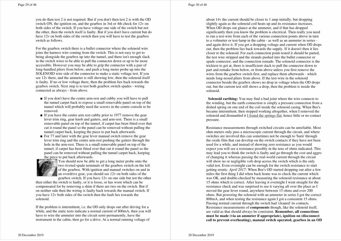
you do then test 2 is not required. But if you don't then test 2 is with the OD switch ON, the ignition on, and the gearbox in 3rd or 4th check for 12v on both sides of the switch. If you have voltage one side of the switch but not the other, then the switch itself is faulty. But if you don't have current but do have 12v on both sides of the switch then you will have to test the gearbox switch as follows.
For the gearbox switch there is a bullet connector where the solenoid wire joins the harness wire coming from the switch. This is not easy to get to being alongside the gearbox up into the tunnel, and there isn't enough slack in the switch wires to be able to pull the connector down or up to be more accessible. However you may be able to grip the connector with a pair of long-handled pliers from below, and push a long meter probe up into the SOLENOID wire side of the connector to make a static voltage test. If you see 12v there, and the ammeter is still showing low, then the solenoid itself is faulty. If no or low voltage there, then the problem lies back towards the gearbox switch. Next step is to test both gearbox switch spades - wiring connected as always - from above.
If you don't have the centre arm-rest and cubby you will have to pull the tunnel carpet back to expose a small removable panel on top of the tunnel which will probably need the screws in the centre console to be removed.
■
If you have the centre arm rest cubby prior to 1977 remove the gear lever trim ring, gear knob and gaiters, and arm-rest. There is a small removable panel on top of the tunnel, if carpet has been fitted over that cut it round the panel so the panel can be removed without pulling the tunnel carpet back, keeping the piece to put back afterwards.
■
For 77 and later with the gear lever manual switch remove the gear lever trim ring and the centre arm-rest pushing the gaiters through the hole in the arm-rest. There is a small removable panel on top of the tunnel, if carpet has been fitted over that cut it round the panel so the panel can be removed without pulling the tunnel carpet back, keeping the piece to put back afterwards.
■
You should now be able to get a long meter probe onto the two riveted spade terminals of the gearbox switch on the left of the gearbox. With ignition and manual switches on and in an overdrive gear, you should see 12v on both sides of the gearbox switch. If you have 12v on one side but not the other
then either the switch is faulty, or it is loose, or has worn which can be compensated for by removing a shim if there are two on the switch. But if on neither side then the wiring is faulty back towards the manual switch. If you have 12v both sides of the switch then the fault lies towards the solenoid.
If the problem is intermittent, i.e. the OD only drops out after driving for a while, and the static tests indicate a normal current of 800mA, then you will have to wire the ammeter into the circuit semi-permanently, have the instrument in the cabin, then go for a drive. At a normal running voltage of
Page 29 of 46
20 December 2019
about 14v the current should be closer to 1 amp initially, but dropping slightly again as the solenoid coil heats up and its resistance increases. When OD drops out glance at the ammeter, and if that has dropped significantly then you know the problem is electrical. Then really you need to run a test-wire from each of the various connection points above in turn to a voltmeter or test-lamp in the cabin - as well as an ammeter in series - and again drive it. If you get a dropping voltage and current when OD drops out, then the problem lies back towards the supply. If it doesn't then it lies closer to the solenoid. For each connection point tested it should be parted, the test wire stripped and the strands pushed into the bullet connector or spade connector, and the connection remade. The solenoid connector is the trickiest to get at, there is insufficient slack to pull the connector down to part and remake from below, or from above unless you first remove the wires from the gearbox switch first, and replace them afterwards - which needs long-nosed pliers from above. If the test-wire in the solenoid connector beside the gearbox shows no drop in voltage when the OD drops out, but the current test still shows a drop, then the problem is inside the solenoid.
Solenoid earthing: You may find a bad joint where the wire connects to the winding, but the earth connection is simply a pressure connection from a dished spring on one end of the coil inside the solenoid casing. When Bee's became intermittent, then stopped working altogether, when I removed the solenoid and dismantled it I found the springs flat, hence little or no contact pressure.
Resistance measurements through switched circuits can be unreliable. Most ohm-meters only pass a microscopic current through the circuit, and where switches are involved this can sometimes not be enough to 'burn' through the oxide film that can develop on the switch contacts if they have not been used for a while, and instead of showing zero resistance as you would expect you will see a resistance possibly in the tens of ohms indicated. This may lead you to think the switch is faulty and go through the cost and aggro of changing it whereas passing the real-world current through the circuit will show no or negligible volt-drop across the switch which is the only valid test. Even overnight can be enough for the switch resistance to start getting erratic. April 2017: When Bee's OD started dropping out after a few miles the first thing I did when back home was to check the current which was OK, and double-checked by measuring the solenoid resistance at about 15 ohms which is correct. After leaving it overnight I went straight for the resistance check and was surprised to see it varying all over the place as I moved the gear lever round, anywhere between 15 ohms and over 200 ohms. But powering the solenoid with an ammeter in series I got the correct 800mA, and when testing the resistance again I got a consistent 15 ohms. Passing normal current through the switch had 'cleaned' its contacts. Resistance measurements of components though, like the solenoid itself, are valid as that should always be consistent. Remember, all connections
must be made (via an ammeter if appropriate), ignition on (disconnect
coil to prevent overheating), manual switch operated, gearbox in an OD
Page 30 of 46
20 December 2019

gear for voltage tests to be valid. If you have an ammeter in circuit that
must also be showing reduced or zero current for the voltage tests to be
valid. If the ammeter shows a normal current i.e. 800mA then there is no point doing voltage tests, as ELECTRICALLY the circuit is working as it should.
Hydraulics: If current tests show still show about an amp flowing when the OD drops out, then the problem isn't electrical, but is mechanical or hydraulic, some of which can be more easy to deal with than others:
The solenoid has three O-rings, and if the medium-sized one of these should fail it may not develop sufficient pressure to engage OD, as it allows oil to escape as if the solenoid had failed to operate. Likewise if the plunger jams, or the ball is not seating properly. The solenoid is accessible from underneath by removing the square information plate beside the sump, draining the oil is not required. Incidentally the small O-ring inside the solenoid assembly, and the large one on the top-plate, contribute to preventing oil leaks, as well as the gasket above the information plate, and the rubber seal around the solenoid wire.
■
There could be problems with the relief valve, accessed by removing the hex plug by the sump, which can be done without draining the oil.
■
There is a non-return valve ball and seat in the pump which could be leaking back, or the plunger may have jammed if has not been aligned correctly or the return spring is weak. This is accessed by removing the sump, which requires draining the oil, and needs a special tool to remove the pump plug (or a pair of stout long-nose pliers with the ends in the holes, turned by grips). I've not had any need to dig-in to the pump but Nathan Peach came up with a really good check when he was investigating his after changing several parts but still not working. He found no oil in the new solenoid so suspected the pump, and after draining the oil and removing the sump he turned the prop-shaft while looking up inside the OD with a torch he could see the pump but it wasn't moving. He went to remove the pump but as soon as he turned the securing plug something clicked into place, and after that he could see the pump operating. The end of the pump that carries the roller has a flat side and a rounded side - the flat side goes towards the rear of the OD, and it's this flat lying against the casing that orientates the pump correctly. Nathan also writes that the pump plug is a lot easier to fit if you use the prop-shaft to turn the lobe of the cam away from the pump!
■
If all that looks good the only thing you can do short of removal and dismantling is use of a pressure gauge, which should show 400 to 420psi (510 to 530psi for the V8) with OD engaged, zero when disengaged. This needs an adapter fitted in place of the relief valve plug beside the solenoid, which can be done without draining the oil. This will obviously need the engine and gearbox to be run with at least one rear wheel off the ground, handbrake off, and the car very safely supported. Remember to switch
Page 31 of 46
20 December 2019
OD in and out when doing a pressure test as you will need to note from the spinning of the wheels and/or relative changes in the speedo and tachometer readings whether OD is actually engaged when the pressure shows it should be. If the problem is that OD drops out after driving for a while then it will need to be run like this for an equivalent time to allow the fault to develop. Insufficient pressure indicates pump solenoid or relief valve problems, or dirt in the passageways. Correct pressure but OD not engaging indicates problems with the actuator pistons, again dirt in hydraulic passageways feeding them, or the sliding member (list not exhaustive, only indicative).
Overdrive Fusing
As with the Fuel Pump it is a good idea to fuse the overdrive circuit to avoid harness damage or total loss of the car to a fire if the wire or overdrive should short out. Later models with the manual overdrive switch on the gearlever are particularly vulnerable because the continual flexing of the wires at the lever.
Cars with the 3-synch gearbox and D-type overdrive have a vacuum switch and relay as well as the manual switch. On these cars the manual switch operates the relay, and it is the relay that operates the overdrive. The relay has its own white (unfused ignition) feed as well as that from the manual switch (yellow), and both should sources should be protected. This can be done with a single in-line fuse, or
more comprehensively with two, see the schematic .
For 4-synch cars with the later LH-type overdrive it depends on where the manual switch is located:
Where the manual switch is on the dashboard it is best to make up an in-line fuse with a male spade on one end and a female on the other, then simply remove the white wire from the switch, put the male end of the new fuse in that, and the female end of the new fuse back on the switch, see here. It can also be inserted as for the column switch below, but will protect less wiring.
◦
For cars with the manual switch on the column short of cutting wires the next best location is at the bullet connector where the yellow wire from the main harness connects to the yellow/red wire in the gearbox harness in the mass of connectors below the pedal box. Note that on V8s at least the gearbox harness joins a spur from the main harness under the heater motor, see here.
◦
For UK cars with the gearlever manual switch insert the fuse in the white and/or white/brown wires (sources vary as to the colours in each) between the main and gearbox harnesses, see here.
◦
For North American cars with the gearlever manual switch there is a double-connector with one white wire from the inertia switch, a white to the fuel pump, and a white/brown to the overdrive switch. I suspect this double-connector is with the others where the firewall and RH inner wing join, but I am not certain. To just fuse the overdrive insert it in the white/brown wire. You could fuse both the fuel pump and the overdrive with a single fuse if you insert it in the white from the inertia switch, see here, but then an OD
◦
Page 32 of 46
20 December 2019

fault will disable the fuel pump. If the inertia switch has spade connectors you could insert it here (using male and female spades on the in-line fuse instead of bullets).
Personally I would use a standard 17amp rated/35 amp blow fuse in the circuit simply because there are (or should be!) a couple of spares of that rating in the main fusebox. That rating may seem higher than required for the overdrive (and pump where applicable) but the purpose of the fuse in nearly all cases in the MGB is to protect the wiring, and that is the correct rating of fuse for the grade of wire used.
Overdrive Pulsing Updated April 2017
Since about 2012 Vee has exhibited a kind of 'pulsing' when switching out of OD after a long fast run, it's as if the OD is engaging and disengaging by itself. Last year someone reported the same thing on the MG Enthusiasts BB, and Stephen Strange of Virginia, USA posted the following:
"One vexing symptom of an Overdrive problem that is not mentioned in the factory manual is a 'pumping' effect during engagement when the car is driven in direct drive, even though when driven in Overdrive all appears normal. This is caused by a problem that is very simple to fix. When the system is operating correctly, a buildup of hydraulic pressure from the pump is directed to the two operating pistons and moves the sliding annular clutch (conical clutch) unit. Its outer brake surface then comes into contact with the stationary brake ring, and then the complete sliding member and the sun gear will consequently cease to rotate. With the solenoid deactivated (i.e., Overdrive switches off), the solenoid plunger does not retract fully, and the springiness in the small O-ring at its tip is enough to push the piston and ball back into its seat once the pressure has bled off. This in turn causes the pressure in the actuating system to increase, which in turn causes the Overdrive to engage again. Past a certain level, there is enough pressure to force the plunger back a bit until the pressure bleeds off and the cycle is repeated again (at a frequency of about every 2 seconds). Normally, as the sliding annular clutch (conical clutch) unit of the Overdrive unit starts to move during the engagement process, the Overdrive unit temporarily loses engagement during the moment between when the inner lining of the sliding annular clutch (conical clutch) leaves its seat on the annulus and the outer lining contacts the stationary brake ring. This is event so brief that it is not noticeable, but in this case, the sliding of the annular clutch (conical clutch) never travels far enough for its outer lining to contact the stationary brake ring before it is pushed back again, so for about a second neither lining is in contact. As soon as the inner lining of the of the sliding annular clutch (conical clutch) engages the annulus, engagement returns with a jerk and stays for a second or so until the of the sliding annular clutch (conical clutch) is again pumped away, and the cycle then repeats itself. The solution to this problem is very simple: fit a thicker gasket under the solenoid cover plate. This will allow the piston to move a bit further back before hitting the solenoid cover plate,
Page 33 of 46
20 December 2019
the extra movement being enough to make the O-ring slide down into its bore instead of simply compressing a bit and functioning like a spring."
I had some questions about the described cause and cure, subsequently found Paul Walbran's web page that at the time described the same problem and solution, and left me with the same questions. As far as a thicker gasket goes, the standard gasket has a large hole which allows the base of the solenoid to sit against the cover. Adding a second or thicker gasket of the same design won't change that, so the plunger will still only move back the same amount relative the solenoid body - which contains the valve seat and ball - as before. Also allowing the solenoid body to come back further will cancel the function of the large O-ring which is to prevent oil leakage down the side of the solenoid body. Also giving more space for the solenoid body could allow the top or the base to move away slightly from the main part of the body, which will reduce the tension on the earthing spring on the end of the solenoid coil. I found even putting sealing compound on both side of the cover gasket, in an attempt (failed) to cure an oil leak, was enough to affect the earthing and hence the electrical operation. One would have to fit a non-standard gasket which held the solenoid body away from the cover - and in the original position relative to the OD body to overcome the problem of oil leakage and coil earthing, but with a smaller hole that allowed the plunger to come back to the cover, to increase the clearance at the valve. However by insulating the solenoid body from the cover you are removing one of the paths through which it can earth, and it will be dependant on a much lighter contact between the sides of the solenoid body and the OD body.
As it has only started happening after 20 years and nearly 100k, I tend to think it is not simply lack of room for the plunger, but something else. The small O-ring Stephen mentions is not at the tip of the plunger, but sits in a groove further down, and prevents oil seeping down to the external cover from where it will almost
certainly leak, despite the gasket and the rubber seal on the wire. It could have swelled with age, making it more difficult for the plunger to slide back down when the coil is de-energised, but it would have to be resisting close to 510psi in the V8, which seems unlikely, and normally O-rings compress with age and lose their sealing function. As the plunger normally is able to move at least 2mm, the question has to be asked - why that is that not enough? It could be an obstruction below the plunger, or in the valve assembly at its tip, or in the relief valve assembly.
Incidentally a very similar pulsing can occur with low oil level, but only when overdrive has been selected. In that case there is insufficient oil pressure to keep the sliding clutch fully engaged with the brake ring, and it pulses between OD engaged and not engaged, in drive as well as on the overrun.
2019: Since Vee's engine and gearbox came out over 2016/17 for an engine rebuild but no work on the gearbox or OD I've not had any pulsing ... but quite possibly because it is now dropping-out electrically on the overrun, with the gear-lever moving forward slightly. I can keep it engaged by pulling the lever hard back and towards me, but it's not something I like doing. I replaced the switch and spent some time fiddling with its shims to no avail - I could reduce them to
Page 34 of 46
20 December 2019
the point that it would engage pulling in 3rd but still drop out in 4th overrun. With the gearbox now whining it has to come out again, and I shall investigate the linkages that operate the switch.
Overdrive Replacement June 2013
A pal has a supercharged roadster and had been having various problems with it failing to engage and disengaging once engaged. Whilst some of the problems seem to have been electrical and were fixed it was still disengaging, and it seemed to be on sudden changes of direction i.e. overtaking i.e. as if 'oil
surge' was causing oil starvation. Low oil level could cause that, but of course that had been eliminated as a possibility some time previously, so he decided to do an oil change and remove the sump and filter. There was a considerable amount of what looked suspiciously like friction material lying on top of the filter - which was quite probably restricting the rate at which oil could pass through the filter into the sump to be picked up again by the pump! After a bit of pondering and discussion with Overdrive Repair Services in Sheffield it was decided the best option was to send it to them and as well as any repairs they would uprate it to V8 spec to cope with the additional torque of the supercharger. He and another pal got the engine and gearbox out as one, removed the OD, parcelled it up and sent it off. He got a nice shiny one back in little more than a week, and I was co-opted to help fit it and do an opportunistic change of the clutch, slave cylinder and slave flex hose at the same time.
First task was to split the engine and gearbox, and the biggest problem was to support the engine partly on the hoist to stop it falling over, and partly on blocks to stop it swinging about, and support the gearbox such that as the two are unbolted there is no tendency for them to change angles in different directions
and put a bending force on the first motion shaft. Really quite difficult, and having split them both ways now I would never ever contemplate removing both if all I were replacing was the clutch. Even if doing something with the gearbox, if I could get the car high enough I would still remove the engine i.e. while the gearbox is firmly attached to the car, then remove the gearbox separately. This was reaffirmed when it came time to put the two together, as there is a limit to the amount of weight two blokes of a certain age can manipulate in four directions while trying to get the splines re-engaged, but more of that later. The crucial thing is to keep an even gap all the way round between the bell-housing and the engine back-plate, while you are separating and joining the two.
With the gearbox off we decided to go for the interesting bit first and refit the OD. For this we had a Workmate to stand the gearbox on its bell-housing so we could lower the OD onto the other end, also recommended by the people in Sheffield. They supply a gasket for the OD/gearbox join which is proper gasket material, and not the flimsy
paper effort supplied by one of the major parts houses. Although the proper gasket, being thicker, will have more ability to cater for minor imperfections in
Page 35 of 46
20 December 2019
the two flanges, we decide to go for belt and braces in the shape of a smear of non-setting joint sealant on both faces of the gasket. Don't use silicone, it will have dried by the time you get the two halves together. Michael had blue Hylomar, I've only ever used red Hermetite, but I have found the Hermetite tends to separate into a liquid and a stiffer paste once the tube has been opened, whereas this Hylomar showed no signs of that. February 2018: However my preferred product now is Loctite Flange Sealant 5699 which takes about ten days to fully cure, and will not skin while assembling.
There are two aspects to be considered when fitting an OD to a gearbox. One is the splines of which more later, and the other is the hydraulic pump cam on the gearbox and the pump plunger on the OD. There is a slight chamfer all round the edge of the cam, and I wondered if this would enable the pump
roller to slide onto the cam as the two were pushed together if the output shaft was turned to present its lowest profile to the pump roller. Both the Leyland Workshop Manual and Haynes use the hallowed phrase "To refit, reverse the removal procedure" - yeah right! I took the cam off the gearbox output shaft - be aware there is a ball bearing in a depression in the shaft which engages in a slot in the cam to drive it, make sure that doesn't fall out!! - and held the cam in the position it would be inside the OD, and it was obvious the pump shaft will have to be pulled back against its return spring at least 1/8" before the two will engage, much more than the chamfer. John Twist recommends grinding a bigger chamfer on part of the cam, but I didn't think much of that idea. We used a length of braided nylon cord that happened to be handy, fed through between the pump shaft and roller, the shaft can be pulled back against its return spring pretty easily with that. The two casings are only about 1/4" apart as the roller meets the cam, so not much space for anything else. But to make things easier it helps if the output shaft is turned so that the cam presents the lowest part of its profile to the pump roller. Easily done, but you are going to have to rotate the OD output flange to align the splines, which could easily turn the gearbox output shaft as well. So as the gearbox was on the Workmate we simply put the gearbox into a gear (any gear will do), turned the cam to the correct position, and closed the workmate jaws onto the first-motion shaft to lock the cam in position.
We picked up the OD and turned it open end down ... and about a cup-full of oil (presumably the residue of what was used for their testing) ran out going all over where we didn't really want it. Lowered the OD over the shaft, and it went down until the studs just started to go through the gearbox
casing holes, and stopped at about a half-inch gap. We thought that might be the pump roller on the side of the cam, so pulled it back with our cord. It moved back and fore freely and made no difference to the gap between the casings, so it must be something else. Looking inside the OD there are two sets of splines, one in line with the other. One of the people at Sheffield had said something about 'moving the lower splines' which didn't make much sense at the time, especially as he qualified it with "But I only repair them, I don't fit them". At first sight they appeared to be in line, both turning as I turn the output flange, so we have another go with the same result. We then made a crude depth-gauge from a long
Page 36 of 46
20 December 2019
screwdriver and a bit of masking tape to measure the distance from the edge of the OD casing to where the two splines meet, and compared that with the gearbox output shaft adding on the half-inch gap, and it came right to the end of the shaft, so the shaft must be going through the first splines, but not the second. A closer look at the two sets of splines shows that although one side appears to be in line - the side I looked first, the other side is noticeably out of line! So a quick call to Sheffield to clarify 'moving the lower splines' and it turns out the inner set are on the one-way clutch, and if you turn the output flange one way the two sets move together, but if you turn it the other way they do move apart. They are set correctly at the rebuilders, but can move in transit, and of course if you turn the output flange. What you have to do is put a long screwdriver down inside the splines, hold the output flange, and turn the inner set anti-clockwise relative to the outer set (they won't move the other way because of the one-way clutch) until the splines are exactly in line. There are no instructions with the OD about refitting it, I don't think it would hurt them to include something to this effect.
Anyway, with the splines aligned we tried again, and this time the OD stopped about 3/4" short, with the studs clear of the gearbox casing! This must be the first set of splines not aligning this time, so pure luck that they did the first twice we tried. The only way we are going to correct this is to turn the output flange, but which way so that we don't upset the alignment of the two sets!? Now if we had to turn the inner set anti-clockwise relative to the outer set to align the two sets, because it won't move clockwise, then it stands to reason that if we turn the flange also anti-clockwise, then the two sets will be locked and so not move out of alignment - OK? A quick practice in the air to work out which way is anti-clockwise with the gearbox and OD standing on end, and I go for it. I turn the flange, then feel a tiny click, which is probably the splines almost engaging. But have I gone to far? I can't turn it back or I will misalign the two sets of splines again, to carry on turning anti-clockwise but slowly, and feel another faint click. This time we waggle the OD a little bit, and it drops, this time with about a 1/4" inch gap. So now we pull on the cord, and bingo it drops the rest of the way - barring the thickness of the cord. So very carefully easy the OD up again about 1/8", and pull the cord out. This is where cord is probably better than wire, anything strong enough might be difficult to pull out and leave scratches.
It's now just a case of putting the lockwashers and nuts on the OD studs ... or is it? Two of the studs don't have enough clearance to get the nuts under, so again we have to ease the OD up just enough to get the nuts under, but not enough to get the roller off the cam! The easiest way of doing this is to use a
flat-bladed screwdriver under one of the studs and lever up carefully while lifting the OD until there is enough space on the other stud, and a couple of finger-tips to get the threads started. The screwdriver keeps the gap consistent, you don't want to drop the stud onto the nut and risk damaging the thread. With that nut started and on a few turns, lever under that one to lift the other stud and get the washer and nut on that. With those two on the other six are easy, then time for a well-earned bacon sarnie!
Page 37 of 46
20 December 2019
After that we change the clutch, then more struggling getting the gearbox back on the engine, keeping it square and aligned in four orientations while turning the OD output shaft (gearbox still in gear) to align the splines, reaffirming that separating
and reattaching them in the car is by far the best way (short of using an engine stand). February 2018: However it subsequently occurred to me that by using, say, four long shafts or studding about the same diameter of the bellhousing bolts, long enough to engage with both halves before the first-motion shaft starts to engage, that would certainly help in keeping the two halves correctly aligned whilst pushing them together. Then refit the remote tower (which has to be removed to remove and refit the OD), and most important - attach the gearbox harness to the switches, solenoid wire and gearbox and engine bracket points before putting the whole back in the car! Final job of the day is to change the clutch slave and flex hose, the latter can be really difficult on the 4-cylinder with the engine in-situ. Reinstallation of engine and gearbox to the car is a job for next day.
Overdrive Sequencer Relay
October 2016: For Graham White's version, with added features such as automatic disengagement when changing between 3rd to 4th, and 'belt and braces' ensuring OD cannot be engaged with reverse, see here.
These are the details of the MkII version. For the MkI version click here, and for an 'all-electronic' version see here.
It may be my age but from time to time I find that I move from 3rd or 4th with overdrive engaged to 1st or 2nd and forget to switch overdrive off. All is well until I change up from 2nd to 3rd, then all of a sudden the overdrive engages again, usually under conditions where it is inappropriate. This means not only do I get the mild and unexpected jolt as it engages, but another one when I manually switch it off until I need it again. This has bugged me for some time and I felt sure I could knock up (i.e. build!) a circuit to prevent it.
August 2013: Following an enquiry about fitting this circuit to a car with the gear lever driver's switch I realised there are a couple of complications. For UK cars it is one of accessibility in that the circuit is inserted between the driver's switch and the gearbox switch, so you have to access those wires under the tunnel. North American cars are even more complicated, see here.
The intention of the circuit is to allow overdrive to be engaged if the manual switch is operated whilst in 3rd or 4th, but to lock it out when I change to any other gear, even when I change back to 3rd or 4th, until the manual switch is turned off and on again. On cars with OD on 3rd and 4th OD remains engaged when moving between the two, unless you move the gear lever out of the 3/4 plane into the 1/2 plane and back again, which will disengage OD and lock it out. Originally I achieved this with just one relay with a single normally-closed contact, but its disadvantage is that it requires a connection to the solenoid side of the gearbox lockout switch and there is the faint possibility that a fault could
Page 38 of 46
20 December 2019

leave overdrive engaged in reverse which would destroy it. This version uses some simple electronics as well as the normally-closed relay and completely eliminates that possibility.
What happens is that the normally-closed contact of the relay is wired in series with the gearbox and manual switches. This means that if any of the manual switch, the gearbox switch, or the relay contact are open overdrive is disengaged, and they all have to be closed before overdrive will engage. Thus it is fully fail-
safe - any fault in the additional circuitry can only cause the OD to either
operate exactly as the factory intended, or not at all, it can never cause it to
operate when it shouldn't be i.e. when reverse gear is selected. So as long as the relay remains released the overdrive operates completely normally, but when the relay operates it prevents the overdrive engaging regardless of the state of the gearbox and manual switches. The circuit is such that if the manual switch is closed and the gearbox switch is open then the relay will operate, and will remain so until either the manual switch is opened or the ignition is switched off. Remember that whenever the relay is operated its normally closed contact is open, and this prevents the overdrive from engaging.
If you look at the diagram you will see that with the manual and gearbox switches closed and the relay released the solenoid operates in series with the two diodes, D1 and D2. Semi-conductor diodes exhibit a small volt-drop when forward-biased, and though this is not enough to affect the solenoid the
voltage developed across the two in series is used to forward-bias transistor T1 via resistor R1 and so switch it on. T1 switched on ensures that transistor T2 is switched off by connecting emitter potential to its base via R2. T2 switched off means that the relay is released, so maintaining the status quo, and overdrive engaged.
If the gearbox is taken out of an overdrive gear the gearbox switch opens, the solenoid is disconnected and overdrive switches out. At the same time the current ceases to flow through diodes D1 and D2 so there is no longer any volt-drop across them. This causes transistor T1 to switch off, which allows transistor T2 to switch on via resistors R2 and R3. Transistor T2 operates the relay which puts another break in the circuit to the solenoid. D3 acts as a 'spark quench' diode to prevent high-voltage back-emfs from the relay from damaging transistor T2 when it switches off and releases the relay. Even if an overdrive gear is selected again and the gearbox switch closes, the relay contact ensures that the solenoid is not energised, so there is still no current flow through diodes D1 and D2, so again the status quo is maintained and overdrive remains switched out.
It is not until the manual switch is turned off, or the ignition is turned off, that the sequencer relay releases, because there is no longer the 12v supply via transistor T2 to keep it operated. But this also means that even when the relay releases there is no voltage supplied to the solenoid so overdrive remains switched out.
Page 39 of 46
20 December 2019
Only when the manual switch is turned on again in an overdrive gear does current flow through diodes D1 and D2, the sequencer relay contact (closed), the gearbox switch (closed) and the solenoid to switch overdrive in again.
There has been some discussion about having a warning light glowing when overdrive is engaged, but with the dash and gear lever switches there doesn't seem much point as it is easy to see and feel whether it is on or off. Less easy with the column switch, and in fact my V8 (column switch) came with a warning light courtesy of a PO. But on the roadster with the sequencer relay there have been a couple of occasions I wasn't sure if overdrive was engaged or not, even though the manual switch was on, i.e. I can't tell if the sequencer relay has operated and locked it out without turning the manual switch off and on again. So an enhancement is to have a warning light that glows only when the sequencer relay has operated i.e. overdrive is manually selected but locked out.
Electronic components: I used some 100v 1A diodes (from Lucas, believe it or not) and 50v switching PNP transistors I happened to have lying around from my Telecom days 25 years ago. The resistors used will depend on which transistors you use, but they are not critical. I think I used 1k ohms in each case selected to give minimum current but reliable operation of the circuit. I mounted the components on a small circuit board such that it could be fitted inside an old Lucas metal can 6RA relay, utilising the spades on the insulated base plate (winding and contacts removed) for its connections to the outside world. The warning light is a red (red being significantly brighter than the green and yellow examples I had in my box of bits) LED in series with a 470 ohm resistor, the pair being connected in parallel with the relay winding, so that whenever the relay is operated the LED glows. Updated September 2010: The relay is a 12v automotive 'changeover', 'single-pole double-throw' or 'SPDT' type (try Googling '12v SPDT auto relay') with five spade terminals - a normally open (87), a normally closed (87a) and a common (30) as well as the two winding terminals (85 and 86), check the diagram on the relay matches up with type S4 here. Note that the circuit includes a protection diode (D3), if using relay type S6 you won't need D3 but must get the relay winding terminals 85 and 86 the right way round or you will blow the transistor. Relay type S5 includes a protection resistor, on its own that may not be enough to protect the transistor, and may alter the parameters of the circuit so is best avoided.
Installing to the car. The electronic module together with an aftermarket relay (with 87 and 87a connections) were mounted side-by-side close to the fusebox using a handy tapped hole that already existed on my 1973 roadster. Once the two units are interconnected they just need an earth/ground connection from a tag under the fixing screw, and two wires - one to the yellow from the main harness - via an in-line fuse if you haven't already fitted one by the manual switch - and one to the yellow/red in the gearbox harness. I've never liked drilling holes in the dash for extras so positioned the led at the top of the cut-out in the dash that
Page 40 of 46
20 December 2019

accommodates the steering column. With my combination of height, seat and steering wheel I can just see the LED from my normal driving position, and being recessed slightly into the cut-out it is clearly visible even in bright sunlight.
Update October 2010:
After realigning the steering and rack columns I find the warning light has moved from being just visible to just invisible, unless I keep leaning forward which is a pain, so a new position has to be found. I settle on the small gap between the end of the crash rail and the door seal, as shown here,
which is conveniently near the dash-switch.
Differences in other years and markets:
The electronics are obviously polarity sensitive and so cannot be used as-is on a positive-earth car. However it should not be beyond anyone capable of building such a circuit to come up with a suitable variant, i.e. reversing the diodes and using NPN transistors.
◦
MkI models use the D-type overdrive and I have not tested the circuit with this unit only the later LH-type. The D-type solenoid has a 17 amp pull-in current and a 2-amp hold in, as opposed to the 1-amp pull-in and hold-in current of the LH-type. Because diodes offer a constant volt-drop when passing a current, two diodes in series will reduce the voltage to the solenoid by twice that forward volt-drop, and hence reduce the current that will flow in the circuit. It's possible this reduced current may prevent the D-type solenoid operating. As a first check before doing anything else you can get a couple of diodes and wire them in series with the manual switch to see what happens.
◦
From the 1977 model year all markets had the manual switch on the gear lever. Cars other than for North America are wired as before but the yellow and yellow/red wires have to be picked up by the gearbox owing to the physical position of the manual switch.
◦
North America '4th gear only' cars were wired differently because the gearbox switch also controlled vacuum advance through the TCSA switch, the order of the gearbox and manual switches is reversed, and the circuit will not work as intended. See here for more information on this model.
◦
Testing:
With the ignition on but engine stopped and the gearlever in 1st, 2nd or reverse turn the manual switch on and off a few times. You should hear the relay click as it operates and releases with the manual switch.
◦
With the manual switch off, select 4th gear, then operate the manual switch. You should not hear the relay click at any time.
◦
Move the gear lever into 1st and you should hear the relay click once as it operates.
◦
Page 41 of 46
20 December 2019
Move the gear lever into and out of 4th a couple of times and you should not hear the relay clicking.
◦
Switch the manual switch off and you should hear the relay click once as it releases.
◦
On the road, get into top gear and the overdrive should engage and disengage as normal as the manual switch is turned on and off.
◦
With the switch on and overdrive engaged move into 2nd and note the revs (which will be higher than in 4th of course). Move the manual switch to off and there should be no change in engine revs.
◦
Go back into 4th and move the manual switch to off and back to on again. If the sequencer relay is doing its job there will be no increase in revs as you switch it off but there will be a decrease in revs as you turn it on again and overdrive engages.
◦
I've used the MkII version over several hundred miles now and it works well, just a glance at the LED tells me if the sequencer relay has locked out the OD, and sometimes the LED catches my eye anyway.
Overdrive - How many were there? Added January 2008
An oft discussed question, opinion being it was 'not many' in North America for some reason when the cars were new, although it is considered a very desirable addition today. Why there weren't many originally I can't imagine - it is eminently suitable for the long distances common in North America, and similar technology to automatics which were very common so that shouldn't have put people off (it didn't in the UK where automatics were rare, and are still uncommon at the time of writing). Maybe buyers just didn't understand what 'Overdrive' was'. Living quite close to Gaydon and The British Motor Museum archive I considered spending some time there counting. Thinking further, I realised I didn't need to go through all the individual build records as 18V engines from August 1971 (North American spec) and November 1973 (all other markets) had different engine types according to whether OD was fitted or not, and these represent very nearly half of all production. So if there were documents showing how many engines of each type were ordered by Abingdon I could just look at those. It was only subsequently I realised that Clausager already contains this information, as the engine number types and quantities are listed in 'Original MGB'! So here they are:
Period Market No OD OD TotalPercent
OD
Aug71-Nov73Home and non-North American export
5201 22240 27441 81
Nov73-Sep74Home and non-North American export
434 7123 7557 94
Page 42 of 46
20 December 2019
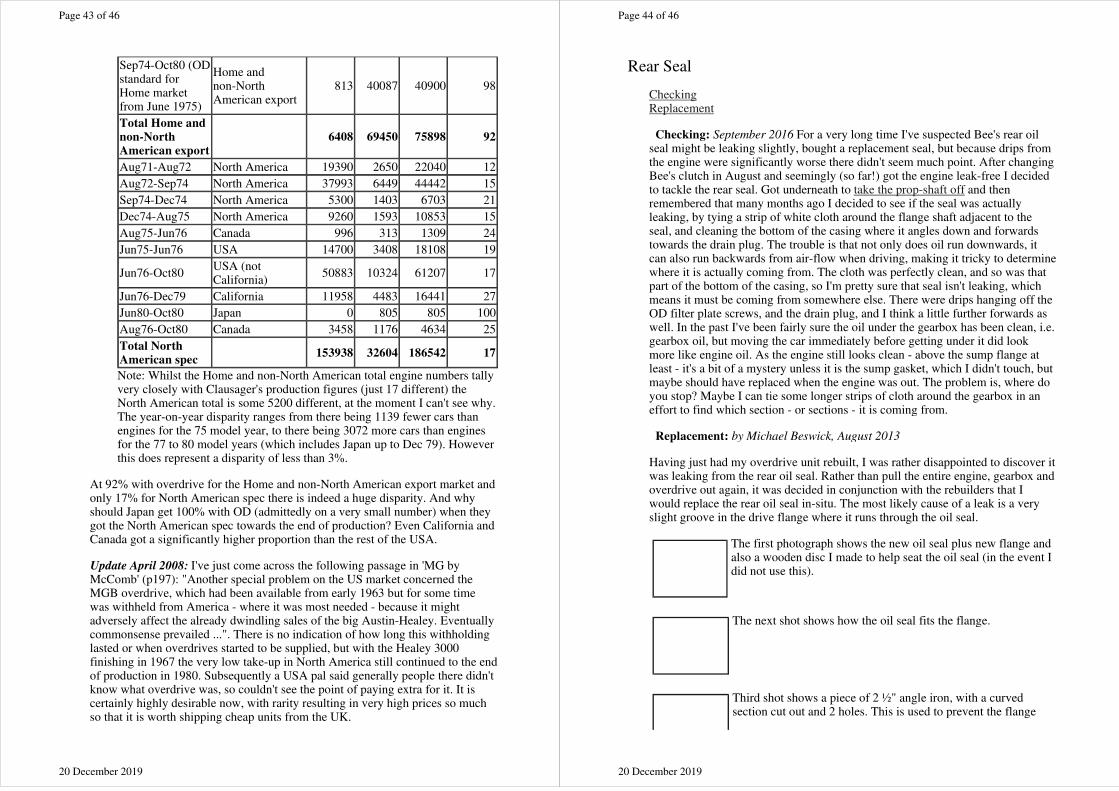
Sep74-Oct80 (OD standard for Home market from June 1975)
Home and non-North American export
813 40087 40900 98
Total Home and
non-North
American export
6408 69450 75898 92
Aug71-Aug72 North America 19390 2650 22040 12
Aug72-Sep74 North America 37993 6449 44442 15
Sep74-Dec74 North America 5300 1403 6703 21
Dec74-Aug75 North America 9260 1593 10853 15
Aug75-Jun76 Canada 996 313 1309 24
Jun75-Jun76 USA 14700 3408 18108 19
Jun76-Oct80USA (not California)
50883 10324 61207 17
Jun76-Dec79 California 11958 4483 16441 27
Jun80-Oct80 Japan 0 805 805 100
Aug76-Oct80 Canada 3458 1176 4634 25
Total North
American spec 153938 32604 186542 17
Note: Whilst the Home and non-North American total engine numbers tally very closely with Clausager's production figures (just 17 different) the North American total is some 5200 different, at the moment I can't see why. The year-on-year disparity ranges from there being 1139 fewer cars than engines for the 75 model year, to there being 3072 more cars than engines for the 77 to 80 model years (which includes Japan up to Dec 79). However this does represent a disparity of less than 3%.
At 92% with overdrive for the Home and non-North American export market and only 17% for North American spec there is indeed a huge disparity. And why should Japan get 100% with OD (admittedly on a very small number) when they got the North American spec towards the end of production? Even California and Canada got a significantly higher proportion than the rest of the USA.
Update April 2008: I've just come across the following passage in 'MG by McComb' (p197): "Another special problem on the US market concerned the MGB overdrive, which had been available from early 1963 but for some time was withheld from America - where it was most needed - because it might adversely affect the already dwindling sales of the big Austin-Healey. Eventually commonsense prevailed ...". There is no indication of how long this withholding lasted or when overdrives started to be supplied, but with the Healey 3000 finishing in 1967 the very low take-up in North America still continued to the end of production in 1980. Subsequently a USA pal said generally people there didn't know what overdrive was, so couldn't see the point of paying extra for it. It is certainly highly desirable now, with rarity resulting in very high prices so much so that it is worth shipping cheap units from the UK.
Page 43 of 46
20 December 2019
Rear Seal
Checking Replacement
Checking: September 2016 For a very long time I've suspected Bee's rear oil seal might be leaking slightly, bought a replacement seal, but because drips from the engine were significantly worse there didn't seem much point. After changing Bee's clutch in August and seemingly (so far!) got the engine leak-free I decided to tackle the rear seal. Got underneath to take the prop-shaft off and then remembered that many months ago I decided to see if the seal was actually leaking, by tying a strip of white cloth around the flange shaft adjacent to the seal, and cleaning the bottom of the casing where it angles down and forwards towards the drain plug. The trouble is that not only does oil run downwards, it can also run backwards from air-flow when driving, making it tricky to determine where it is actually coming from. The cloth was perfectly clean, and so was that part of the bottom of the casing, so I'm pretty sure that seal isn't leaking, which means it must be coming from somewhere else. There were drips hanging off the OD filter plate screws, and the drain plug, and I think a little further forwards as well. In the past I've been fairly sure the oil under the gearbox has been clean, i.e. gearbox oil, but moving the car immediately before getting under it did look more like engine oil. As the engine still looks clean - above the sump flange at least - it's a bit of a mystery unless it is the sump gasket, which I didn't touch, but maybe should have replaced when the engine was out. The problem is, where do you stop? Maybe I can tie some longer strips of cloth around the gearbox in an effort to find which section - or sections - it is coming from.
Replacement: by Michael Beswick, August 2013
Having just had my overdrive unit rebuilt, I was rather disappointed to discover it was leaking from the rear oil seal. Rather than pull the entire engine, gearbox and overdrive out again, it was decided in conjunction with the rebuilders that I would replace the rear oil seal in-situ. The most likely cause of a leak is a very slight groove in the drive flange where it runs through the oil seal.
The first photograph shows the new oil seal plus new flange and also a wooden disc I made to help seat the oil seal (in the event I did not use this).
The next shot shows how the oil seal fits the flange.
Third shot shows a piece of 2 ½" angle iron, with a curved section cut out and 2 holes. This is used to prevent the flange
Page 44 of 46
20 December 2019
rotating thus allowing you to undo the big nut the centre of the shaft (which is 1 1/8 AF, same as the front hub nuts).
First job is to drain the oil. Also be aware that when the oil seal is removed a certain amount of oil will escape. As it took me a while to remove the prop shaft and the central nut on the overdrive there was very little oil left in the gearbox.
Undoing the nuts on the prop shaft to the overdrive flange requires a ½" AF open-ended spanner, everything else jams. The bolts are a special type with a flat on them that allows them to fit down the flange and prevents them rotating. Once this is undone you can turn your attention to the flange on the differential. Again it is a
half inch open ended and a ring spanner to remove them. I marked the position of the rear flange on the prop shaft and the corresponding position on the flange on the differential. This is probably not necessary as prop shafts are dynamically balanced off-car and should run true with the flanges in any orientation. (As I was removing and replacing the flange in the overdrive there was little point in making similar marks for the front of the prop shaft). The prop shaft can then be fed forwards and downwards and removed.
The central nut of the overdrive was pretty tight so I needed to use the piece of angle iron which jammed against the transmission tunnel. Using a 2 foot breaker bar and pulling the angle iron towards me I managed to loosen the nut. The splined flange then simply pulls forwards and off.
(See also this 'universal' tool made from B&Q flat steel strip).
I had been told that the seal could be removed using a screwdriver, but I found that I needed the correct tool. I borrowed one from my local garage but Machine Mart do them for about £6. It resembles a small ice pick. It is obvious how to use the pick - set it so there is leverage then a sharp pull will
remove the seal. It seems that the tool pulls out the spring that forces the lips of the seal against their respective faces. Thus deformed the seal comes out easily. Care needs to be taken to ensure the tip of the "pick" rests on the seal and does not score the face of the housing-thus producing another oil leak....
Replacing the new oil seal is simply a matter of oiling it all round and then using a large socket (or equivalent drift), and tapping it home ensure it is square. I then used a soft-faced mallet to ensure the seal was flush all the way round.
The special prop-shaft bolts have to be fitted to the drive flange before the flange is fitted to the gearbox or OD. It is worth cleaning up the threads on the bolts with a die. Trying to get the nut on a semi-captive bolt is a fiddle, as the yokes of the U/J get in the way.
Oil the lip of the seal and the flange, replace the splined flange, and fit the washer and nut. The large central nut needs to be tightened to 55 foot pounds and I discovered by putting the car in second gear that I was able to achieve this. It may
Page 45 of 46
20 December 2019
well be that using bottom gear would be sufficient to enable this nut to be undone and therefore the piece of angle iron would not be necessary.
Slide the prop in from the gearbox end and reconnect the diff flange and the o/d flange. The diff is relatively easy, but the o/d one is a fiddle (again!).
Replace the drain plug and refill with oil.
I could have refilled with oil before attaching the prop-shaft, then started the engine, engaged 3rd or 4th and overdrive which would have served two purposes - firstly it would have allowed me to top-up and correct the oil level there and then as it always drops a significant amount the first time the gearbox is run and OD engaged, and also to see if the new seal leaked. However I only thought this after I finished reconnecting the prop.
© Copyright 1999 to 2019 I.T. Answers. http://www.mgb-stuff.org.uk/
Page 46 of 46
20 December 2019