Gear Design 'Options · in AGMA 110.04 "Nomenclature of Cear Tooth Wear and Failure." The two...
11
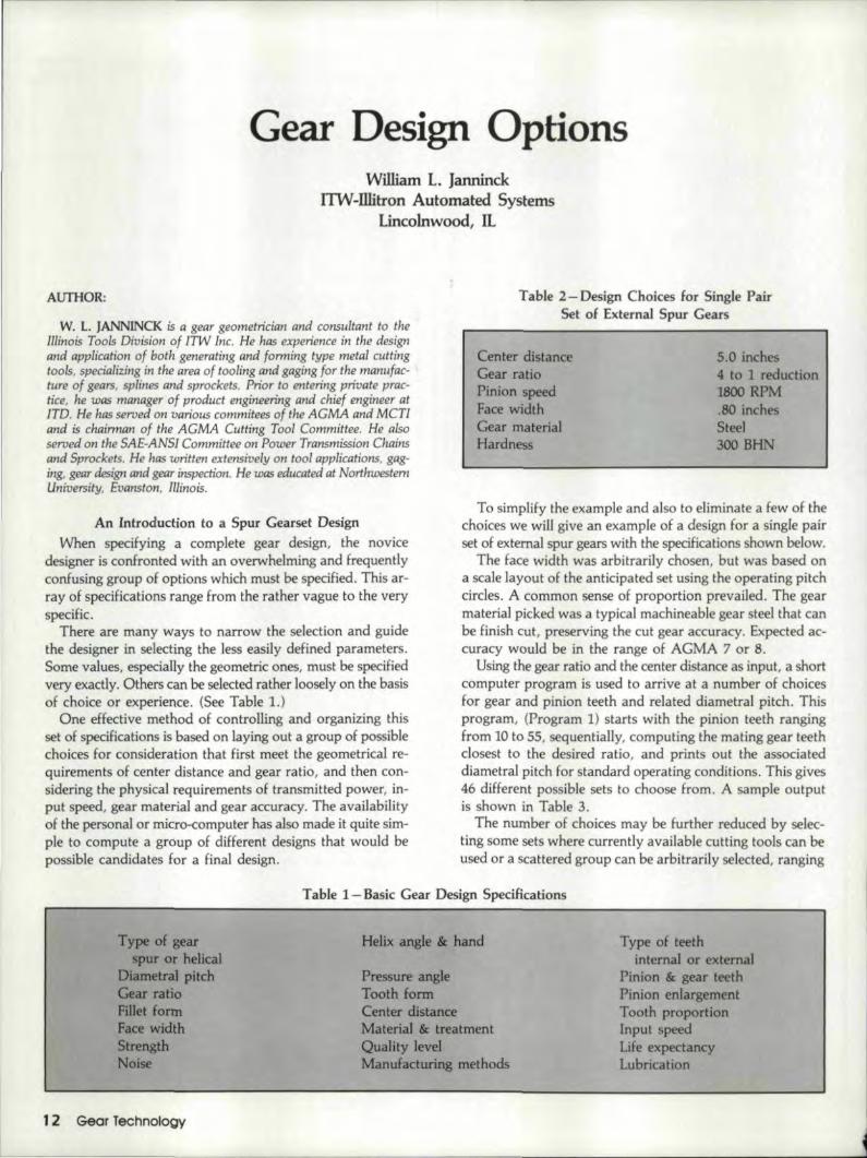
AUTHOR: Gear Design 'Options WWiam L. [anninrk .ITW-Illitron Automated Systems lincolnwood, IL w. L. JANN]NCK is a gear geometrician and consultant to the Illinois Tools Division of ITW Inc. He has experience in the design and application of both generating and forming type metal cutting tools, specializing in the area of tooling and gaging for the manufac- ture of gears, splinesand sprockets. Prior to entering private prac- tice, he was manager of product engineering and chief engineer at lTD. He has served on various commitees of the AGMA and MCT! and is chairman of the AGMA Cutting Tool Committee. He .also served on the SA£-ANSJ Committee on Power Transmission Chains and Sprockets. He has written extensively on tool app/ica.tions, gag- ing, gear design and gear inspection. He UIQS educated at Northwestern University, Evanston, Illinois. An Introdu.ction to a Spur Gearset Design When specifying a complete gear design, the novice designer is confronted with an overwhelming and frequently confusing group of options which must be specified. This ar- ray of specifications range from the rather vague to the very specific. There are many ways to' narrow the selection and guide the designer in selecting the less easily defined parameters. Some values, especially the geometric ones, must be specified very exactly. Others can be selected rather loosely on the basis of choice or experience. (See Table 1,) One effective method ·of controlling and organizing this set of specifications is based on laying out a group of possible choices for consideration that first meet the geometrical re- quirements of center distance and gear ratio, and then con- sidering the physical requirements of transmitted power, in- put speed, gear material and gear accuracy. The availability of the persona] or micro-computer has also made it quite sim- ple to compute a group of diHerent designs that would be possible candidates for a final design. Table 2- Design Choices for Single Pair Set of External. Spur Gears Center distance Gear ratio Pinion speed Face width Gear material Hardness 5.0 inches 4 to 1 reduction 1800 RPM .80 inches Steel 300 BHN To simplify the example and also to eliminate a few of the choices we will give an example of a design for a single pair set of external spur gears with the specifications shown below. The face width was arbitrarily chosen, but was based on a scale layout of the anticipated set using the operating pitch circles. A common sense of proportion prevailed. The gear material. picked was a typical machineable gear steel that can be finish cut, preserving the cut gear accuracy. Expectedac- curacy would be in the range of ACMA 7 or 8. Using the gear ratio and the center distance as input, a short computer program is used to arrive at a number of choices for gear and pinion teeth and related diametral pitch .. This program, (Program 1) starts with the pinion teeth ranging from 10 to. 55., sequentially, computing the mating gear teeth closest to the desired ratio, and prints out the associated diametral pitch for standard operating conditions, This gives 46 different possible sets to choose from. A sample output is shown in Table 3. The number of choices may be further reduced by selec- ting some sets where currently available cutting tools can be used or a scattered group can be arbitrarily selected, ranging Table 1- Basic Gear Design Specifications Type of gear spur or helical Diarnetral pitch Gear ratio Fillet form Face width Strength Noise Helix angle & hand Pressure angle Tooth form Center distance Material & treatment Quality level Manu.facturing methods Type of teeth internal or external Pinion & gear teeth Pinion enlargement Tooth proportion Input speed Life expectancy Lubrication 12 Gem Technology
Transcript of Gear Design 'Options · in AGMA 110.04 "Nomenclature of Cear Tooth Wear and Failure." The two...
AUTHOR:
Gear Design 'OptionsWWiam L. [anninrk
.ITW-Illitron Automated Systemslincolnwood, IL
w. L. JANN]NCK is a gear geometrician and consultant to theIllinois Tools Division of ITW Inc. He has experience in the designand application of both generating and forming type metal cuttingtools, specializing in the area of tooling and gaging for the manufac-ture of gears, splinesand sprockets. Prior to entering private prac-tice, he was manager of product engineering and chief engineer atlTD. He has served on various commitees of the AGMA and MCT!and is chairman of the AGMA Cutting Tool Committee. He .alsoserved on the SA£-ANSJ Committee on Power Transmission Chainsand Sprockets. He has written extensively on tool app/ica.tions, gag-ing, gear design and gear inspection. He UIQS educated at NorthwesternUniversity, Evanston, Illinois.
An Introdu.ction to a Spur Gearset DesignWhen specifying a complete gear design, the novice
designer is confronted with an overwhelming and frequentlyconfusing group of options which must be specified. This ar-ray of specifications range from the rather vague to the veryspecific.
There are many ways to' narrow the selection and guidethe designer in selecting the less easily defined parameters.Some values, especially the geometric ones, must be specifiedvery exactly. Others can be selected rather loosely on the basisof choice or experience. (See Table 1,)
One effective method ·of controlling and organizing thisset of specifications is based on laying out a group of possiblechoices for consideration that first meet the geometrical re-quirements of center distance and gear ratio, and then con-sidering the physical requirements of transmitted power, in-put speed, gear material and gear accuracy. The availabilityof the persona] or micro-computer has also made it quite sim-ple to compute a group of diHerent designs that would bepossible candidates for a final design.
Table 2- Design Choices for Single PairSet of External. Spur Gears
Center distanceGear ratioPinion speedFace widthGear materialHardness
5.0 inches4 to 1 reduction1800 RPM.80 inchesSteel300 BHN
To simplify the example and also to eliminate a few of thechoices we will give an example of a design for a single pairset of external spur gears with the specifications shown below.
The face width was arbitrarily chosen, but was based ona scale layout of the anticipated set using the operating pitchcircles. A common sense of proportion prevailed. The gearmaterial. picked was a typical machineable gear steel that canbe finish cut, preserving the cut gear accuracy. Expectedac-curacy would be in the range of ACMA 7 or 8.
Using the gear ratio and the center distance as input, a shortcomputer program is used to arrive at a number of choicesfor gear and pinion teeth and related diametral pitch .. Thisprogram, (Program 1) starts with the pinion teeth rangingfrom 10 to. 55., sequentially, computing the mating gear teethclosest to the desired ratio, and prints out the associateddiametral pitch for standard operating conditions, This gives46 different possible sets to choose from. A sample outputis shown in Table 3.
The number of choices may be further reduced by selec-ting some sets where currently available cutting tools can beused or a scattered group can be arbitrarily selected, ranging
Table 1- Basic Gear Design Specifications
Type of gearspur or helical
Diarnetral pitchGear ratioFillet formFace widthStrengthNoise
Helix angle & hand
Pressure angleTooth formCenter distanceMaterial & treatmentQuality levelManu.facturing methods
Type of teethinternal or external
Pinion & gear teethPinion enlargementTooth proportionInput speedLife expectancyLubrication
12 Gem Technology

Table 3 - Available choices of teeth for spur gear sets ..
Center Distance - 5Target Gear Ratio - 4
Pinion T. Gear T. Act. Ratio Diam. Pitch10 40 4.0000 5.0000011 44 4.0000 5.5000012 48 4.0000 6.0000013 52 4.0000 6.5000014 56 4.0000 7.0000015 60 4.0000 7.5000016 64 4.0000 8.0000017 68 4.0000 8.5000018 72 4.0000 9.0000019 76 4.0000 9.5000020 80 4.0000 10.0000021 84 4.0Cl00 10.5000022 88 4.0000 11.0000023 92 4.0000 11.5000024 96 4.0000 12.0000025 100 4.0000 12.5000026 104 4.0000 13.0000027 108 4.0000 13.5000028 112 4.0000 14.0000029 116 4.0000 14.5000030 120 4.0000 15.0000031 124 4.0000 15.5000032 128 4.0000 16.00000
33 132 4.0000 16.5000034 136 4.0000 17.00000
35 140 4.0000 17.5000036 144 4.0000 18.0000037 148 4.0000 18.5000038 152 4.0000 19.0000039 156 4.0000 19.5000040 160 4.0000 20.0000041 164 4.0000 20.5000042 168 4.0000 21.0000043 172 4.0000 21.5000044 176 4.0000 22.0000045 180 4.0000 22.5000046 184 4.0000 23.0000047 188 4.0000 23.5000048 192 4.0000 24.0000049 196 4.0000 24.50000
50 200 4.0000 25.0000051 204 4.0000 25.5000052 208 4.0000 26.0000053 212 4.0000 26.5000054 216 4.0000 27.0000055 220 4.0000 27.50000
Program 1 - 'Iooth Selector Program.
10 REM - Toothsel.bas20 REM - This program develops a series of choices of gear
teeth sets30 REM - for a specific center distance and ratio desired.40 KEY OFF:CLS50 DIM NP (55) ,NG(55) ,ACTR(55) ,DP(SS)60 INPUT "Center Distance ";CD70 INPUT "Ratio Desired" ;RATIO80 FOR 1-10 TO 5590 NP(I)-I:NG{I)-INT(I*RATIO+ .5)100 ACTR (1)-
NG(I)/NP(I):DP(I) - (NP(I) +NG(1))/2/CD110 NEXT I120 LPRINT" Available choices of teeth for spur gear
sets."1.30 [PRINT140 LPRINT'150 LPRINT'160 LPRINT170 LPRINT" Pinion T. Gear T.Ratio Diam. Pitch"180 FOR 1-10 TO 551902$-" ## #H# ##IUIII# 11#·11#1/#1"200 LPRINT USING Z$;NP(I) ;NG(I);ACTR(I);DP(I)210 NEXT I
Center Distance - ",CDTarget Gear Ratio - ",RATIO
Act.
through various teeth numbers and pitches. For example, thesample list in this case contains commonly available pitchessuch as 5, 6,8, 10, U, 14, 16 and 20 .. If an odd target gearratio or an uneven center distance is used, the possibility ofstandard diametral pitches is reduced.
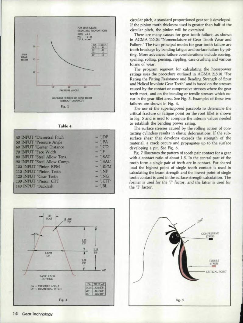
If the teeth versus pressure angle chart for natural. under-cut show-n in Fig .. 1 is examined,the choice will be guidedaway from the lower pinion teeth numbers and lower pressureangles because natural. undercutting causes poor gearoperating conditions and also reduces strength.
In the example case the first likely choice is a 16-64 toothgearset of8DP and 20 or 25° pressure angle. The next choicewould be 20-80. teeth of lODP in 20. or 25° pressure angie,and so on thru 20DP.
Actually 'there isa great deal of flexibility in gear designand long addendum pinions and short addendum gears. callbe used to avoid or reduce undercutting. It is also possibleto depart from the specified diarnetral pitch by a smallamount. resulting inan oversize or undersize operating con-dition on center distance,
A flexible computer program was written toaccomodateboth standard and non-standard conditions and to. freeze thetotal gear geometry for a particular gear set. The input valuesrequired to. run the program are listed in Table 4.
The program has a standard basic rack embedded withinit for 14.5 thru 25 PA as shown in Fig .. 2. This basic rackis used, along with the circular tooth thickness on the pinionand the backlash desired in the set to do a complete geardesign. If the pinlon tooth thickness is set at one half of the
May/June 1987' 13
fOR spuR GEARSSTANDARD PROPORTIONS
ADD. -1.0WD - Z.UTIP R. -.300
SPURCEARTEETH 20
10
15" ,ZQ 25-
PRESSURE ANGLE
MJNIMUM NllMBER Of CEAR TEETHWITliOUT UNDERCUT
Fig. 1
Table 4
- ",DP- ",PA
40 INPUT "Diametral PitchSO INPUT "Pressure Angle60 INPlTl" ''Center Distance70 INPUT "Face Width80 INPUT "Steel Allow Tens.90 INPUT "Steel Allow Compo100 INPUT "Pinion RPM110 INPUT ''Pinion Teeth120 INPUT "Gear Teeth130 INPUT "Pinion CIT140 INPUT '1Backlash
- ",CD- ",F- ",SAT- ",SAC- ",RPM- ",NP- ",NG- ",CTP- ",Bl
1.25DP
--~~---l.S-r06-----1~-------+'-- ~~
~-------~------~---~~[---L!-WBASIC RACK
CUTIING
PA - PRESSURE ANGLEDP - DIAMETRAL PITCH
PA TIP FLAT1405 I .924/DP2() I .bel/DP25 I .405/DP
Fig. 2
14 :Gear Technol'ogy
circular pitch, a standard proportioned gear set is developed.If the pinion tooth thickness used is grea ter than half of thecircular pitch" the pinion will be oversized.
There are many causes for gear tooth failure, as shownin AGMA 110.04 "Nomenclature of Cear Tooth Wear andFailure." The two principal modes for gear tooth failure aretooth breakage by bending fatigue and surface failure by pit-ting. More advanced failure considerations include scoring,spailing, rolling, peening, rippling, case crushing and variousforms of wear.
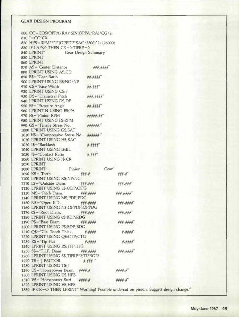
The program segment for calculating the horsepowerratings uses the procedure outlined in AGMA 218.01 "ForRating the Pitting Resistance and Bending Strength of Spurand Helical Involute Gear Teeth" and is based on the stressescaused by the contact or compressive stresses where the gearteeth meet, and on the bending 'Or tensile stresses which oc-cur in the gear fillet area. See Fig. 3. Examples of these twofailures are shown in Fig .. 4.
The use of the superimposed parabola to. determine thecritical fracture or fatigue point en the root fillet is shownin Fig. 5 and is used to compute the interim values neededto. establish the bending power rating ..
The surface stresses caused by the rolling action of con-tacting cylinders results in elastic deformations. If the sub-surface shear that develops exceeds the strength of thematerial, a crack occurs and propagates up to the surfacedeveloping a pit. See Fig. 6.
Fig. 7 illustrates the pattern of tooth pair contact for a gearwith a contact ratio of about 1.5.. In the centra] part of thetooth form a single pair of teeth are in contact. For sharedload the highest point of single tooth contact is used incalculating the beam strength and the lowest point of singletooth contact is used in the surface strength calculation. Theformer is used for the 'T' factor, and the latter is used :forthe 'T' factor.
fig . .3
TENSIL£STRfS5
---- CRITICAL POINT

fiB. 4- Types ofstress, failureson iI gear tooth
~ - Destructivepitting
b-SpaI]ing
fi . 5
HIGHEST POINTFOR SINGLE TOOTH
CONTACT
CRITICALPOINT
t
LOAD
[1~~TILOe<>RMAnON
"REA
,---..-
SUKIA([ CO!'-'TACTSTII:E55
fiB. 6
The AGMA equations for the bending and pitlingpowerratings are shown below, Hrst with all the K and C factorsand, then" in simplified form without these facl,ors.
PAT - np d Kv .' ~ '•. _1_ '.'SAT Kl
lZ6,OOO KA Pd KsKM KR KT
np - Pinion rpmd - Pinion Opel. p.d,F - Gear fa e
Pd - Diarnetral pitch1 - Geom. factor-bending
SAT - Tensile stress no.
PAT - np d. ~ • J .' SAT126.000 Pd
np F126,000
•
np - Pinion rpmF - Gear IaceI - Geom. factor- pittingd Pinion Oper. p.d.
SAC Surface camp. stress no.ep Elastic coeH.
(2)
The factorscan generally be used as 1.0 and can mainlybe considered as warning flags to induce some thought onthe part of the designer. The flags are as Iellows:.' Ka& Ca - application factor which considers the even
or shady nature of the prime mover and theabsorbing load;
• Kv &: Cv - ,related to, the effect that dynamicaJly inducedloads might cause, usually due to highervelocities;
l PAIRTOOTH CONT ....CT
HI(.HBT I I''T'>INGI • rAIR CDNT /lCT/ ~''''''".
SI'l1RrlNIONTOOTH
IFiR. 1

• Ks&: Cs - used in consideration of the effect that theactual physical size of the teeth might have;
.' Km &: Cm -warn. about theeffect of improper loaddistribution across the gear face;
• Kl & CI - related to gear life. Normal life is plannedfor many millions of stress cycles and ismodified for shorter life needs. See Fig. 8
• Kr&: Cr - reliability factors normally expecting lessthan 1 failure in 100;
• Kt &: 0 - temperature factors warning that gears nor-mally do not exceed 2S0"F;
• Cf - consideration factor for the effect of surfacefinish on the surface strength;
• Ch - is a factor for the ratio of hardness betweenthe gear and pinion.
Again, for simplicity the K &: C factors will be used as 1.0,although some consideration has to be given Ito the applica-tion factor Ka&: Caand the reliabiliry factor Kr &: Cr in thefinal selection, as they are important and significant.
For the gear material chosen, steel at 300 BHN,the AGMAsuggests the allowable tensile stress number as 40,000 andthe allowable compressive stress number as 130,000 for input,
The complete computer output for one gear set design isshown in Table S. At this point we can tell if the powercapacity of these designs will meet the needs and with wha.treliability or safety factor.
Noise Consid.erationsGear noise is complex and difficult to analyze, but is us-
ually related to gear accuracy. For equivalent accuracy amonggears with various pressure angles, it has been observed thatlower pressure angle gears are quieter and, conversely, hjgherpressure angles are noisier. The relationship is shown inFig. 9. If we have sufficient capacity in the gears designed,we could choose the lower pressure angle f.or a quieter set.This does not mean sets with higher pressure angles cannotbe quiet, but they will probably require a higher level or gearaccuracy.
~ENDJNG STRENGTHUFE FACTOR
GEAR MAIERIAb;STED.
JOO BHN
UFEFACTOR
111' 10' 10'10 10' 10'
NUMBER Of LOAO CYClES
Fig. 8
16 Gear Technologv
10'
IDEBIUIRRS 'GEARSFAST
* SET-UPSTAKE
SECONDS* INTERNJl\L-EXTERNALSPUR & HELICAL GEARS
~O' 20 INCHES D,IAMETER'11707 McBean Drive, EI Monte, CA 9'1732
181BJ 442-2898CIRCLE A-nON READER REPLYCARD
Table 5 - Complete Computer Output forOne GeM Set Design
Center Distance 5.0000Gear Ratio 4.0000Face Width 0.800Diametral Pitch 10.0000Pressure Angle 20.0000Pinion RPM 1800.00Tensile Stress No. 40000Compressive Stress No. 130000Backlash 0.0020Contact Ratio 1.691
Pinion GearTeeth 20.0 80.0Outside Diam. 2.200 8.200Pitch Diam. 2.0000 8.0000Oper. P.O. 2.0000 8.0000Root Diam. 1.750 7.744Base Diam. 1.8794 7.5175Cir. Tooth Thick. 0.1571 0.1551Tip Rat 0.0695 0.0778T.l.F. Diam. 1.8850 7.8547J FACTOR 0.368Horsepower Beam 33.6Horsepower Surf. 15.9

K1irlg,elr1bergintroduces the fastest. .. most accuratecomplex worm and thread 'grinder available ..... any-where in the world! TM CNC controlled HNC·35 storesdata for up to 9601 complex shapes, reducing set-upto 10·15 minutes ... a fra.ction of the time required withmechanic-aUy contro'lled ,grinders.The HNC-35 iSllersatll'e, too. It performs, c!reep·feedgrindingl from the solid, eliminating the needter pre-liminary milling of worms, threads and rotor:s. It's twomach,ines in 'one ... with the high de{lree IQfaccuracyyIQu'dexpect from Klingelnberg.
The CNC con'trol.led HNC-35,Wo:rm and 'Thread G'rind~e'r
The HNC·35 is available wi,th a mechanical dresser oran optional CNC dresser. f.or s,pecla!11forms and flanks.Whether you produce small quantities or long pr.od:uo-tion runs, the IFASTset-up ... IFAST cyclingl ... HINC-35 will improve yIQurwerm and thread;lprod:uctivity.For additional lnformarlon and a copy of our ,catalog,contact: Killingeinber,g Corporatlon,15200 FoltzIndustrial Parikway~.Clevela_ndl.,0HI44136. 'Or, phone'(21,6),572~2100 for an extra FAST response.

Another area of consideration if noise reduction is of greatimportance is the use of non-standard working depth gears,such as stub or shorter working depth or extended workingdepth. See Fig. 10..
Stub teeth are very rigid and tend to be noisier than thelonger extended tooth fOnTIS where more tooth flexure is pres-ent. These tooth depth systems require separate geometricalconsiderations for design especially in regard to the minimumnumber of teeth.
Strength ConsiderationsIf maximum strength is of significant importance, then
higher pressure angles. would be chosen.as is shown in Fig.11. Here the relationship is shown for strength versus pressureangle, where the strength increases with increasing pressureangle. This isaJso confirmed later using the AGMAhorsepower capacitycalculations.
For the gear material chosen, the computations forhorsepower show the bending strength of the pinion is greaterthan the surface strength. This is quite typical of steel or othermaterials with insufficient surface strength. Typically suchgears wear out rather than failing by fracture. It is preferable,obviously, to have a gear set fail progressively by wear ratherthan catastrophically by breakage.
The results of some 15 different program Funs are sum-marized in Table 6. The horsepower based on bending andsurface strength is tabulated, Several things can be noted ..First in the pitch range chosen all the sets have higher bend-ing strength than surface strength. Second, the surfacestrength goes up as the teeth get smaller, and third, the bend-ing strength goes down as the teeth get smaller. Fig. 12presents a graphical comparison of the computations for the20"PA group. In essence the surface strength is fairly levelacross the entire pitch range while the bending strengthdecreases with the finer pitches ..
ReliabilityTo reduce the chance of failure in the gear set, the Kr &
Gr factor as suggested by AGMA can be considered, The fac-tor for high reliability, less than 1 in 1000 failures, is 1.25,
RElATIVENOISE
2.0
2DPRESSURE ANGLE
II
I
--I
COMPARISON OF NOISEWITH PRESSURE ANGLE
Fig. 9
J' 8 Gear TechnologV
RELAT1VENOlSE
~ , -
l.~ 20 3.0 WORKING D,ErTHb- __ ~-L ~ _
CONTACT RATIO1.1 1.5 1.Z
-m--;.JI-\:-l
STUB EXTENDEDST...ND ...RD
WORKING DEPTH
Fig. 1.0
RElATlVCSTRENGIH:
PRESSURE ANGLE
COMPARISON Of STRENGTHWITH' PRESSURE ANGLE
fig. n
srun 20 P.....
HORSE-POWER
LSURF ...CE
10 1.8 zo12 14 16
OIAMETRAL PITCH
Fig. 12
(continued on page 42)

GEAR DESIGN OPTIONS .....(continued from page 18)
Table 6
PA DP HPC HPB I
10 12.7 26.7 I
12 13.4 24.1 ,
14.5 14 13.8 22.016 14.0 20.220 14.3 17.310 15.9 33.612 16.7 30.0
20 14 17.1 27.116 17.5 24.620 17.9 20.810 18.8 40.312 19.6 35.8
25 14 20.1 32.116 20.5 29.0
I20 21.0 24.4
and that for very high reliability or less than 1 in 10,000failures is 1.5. The computed capacity would be reduced inaccordance with the degree DE reliability desired.
CommentsThe opportunity to use a computer to assist in gear design
can present the designer with a large choice of possible can-didates. Exercising optionsand choices can help in zeroingin on a final selection, but obviously there is no one designthat fits all requirements. Many different. gear 5 ts can besuitable.
Designers are not restricted to standard pressure angles orpitches nor to standard tooth forms. Appropriate basic datacan be placed in the program if desired, for example, to useexisting tooling even if metric module, to reduce costs or 'timedelays.
No gear design is really considered final or so perfect thatthe parts can go into production without some model testingor pilot manufacturing. It is at this point that the unforseenfactors can be dealt with.
References·:1. AGMA 110.04-1980, "Nomenclature of Gear Tooth Failure
Modes:' American Gear Manufacturers Association, Arlington.Virginia.
2. AGMA 218.01-1982, "For Rating the Pitting Resistance andBending Strength of Spur and Helical Involute Gear Teeth.".AmericanGear Manufacturers Association, Arlington, Virginia.
This article was first presented at the SME Gear Processingand Manufactur-ing Clinic. Schaumburg, lL NOli. 11-13, 1986.
120 INPUT "Gear Teeth- • ,NG130 INPUT "Pinion CIT - • ,CTP140 INPUT "Backlash _. ,BL150 PRINT" Program in progress, turn printer on, please."160 HADD-1.25/DP:TIPR-.3/DP:HDED=1/DP:CLR-.25/DP170 HTF -1.570S/DP-.2 *HADD*TAN(PA/RA)180 TCD-(NP+NG)I2!DP190 PDP-NP/DP:PDG-NG/DP.:PRP-PDP/2:PRG-PDG/2200 BDP-PDP~COS(PA/RA):BDG-PDG*COS(PA/RA)210 OPPDP-2"'CD"'NPI (NP+NG):OPPDG-rCD"NG/(NP+NG)220 OPPRG-OPPDG/2:0PPRP-OPPDP/2230 CP-PI/DP:CSP=CP-CTP:BRG-BDG/2:BRP-BDP/2:BP-CP*COS(PA/RA)240 PDED-(CSP-HTF)/2/TAN(PA/RA)250 RDP-PDP-2*PDED
Gear Design Program
10 REM spurgear.bas20 CLS:KEY OFF30 PI-3.141592654tt:RA-180/PI40 INPUT "Diametral Pitch50 INPUT "Pressure Angle"60 INPUT "Center Distance"70 INPUT "Face Width80 INPUT "Steel Allow Tens.90 fNPUT "Steel Allow Compo100 INPUT "Pinion RPM110 INPUT "Pinion Teeth
-",DP"-·,PA-",CD-",F-",SAT-",SAC-",RPM-",NP
42 Gear Technology(continued on page 44)

Barber-Colman AnnouD,ces PDQ HobsThree week deliveryof special ..,formhobalWe're stocking machined blanks, coveringthe DP range of 3 to 100, ready for finishgrinding. (Refer to chart below.)
Call our toll-free hot line (800/435-4176) withyour order and tooth form details ..Or sendus your tooth form by FAX (815/877-o.264).W·e'J] CAD design the cutting tool, formthe grinding wheel, and ship the tools in2-1/2 weeks.
Scope: The program covers gear hobs, invo-lute spline hobs, straight sided serrationhobs, and parallel key spline hobs. Notcovered are shanks, tapered bores or periph-ery, or dutch keyways. And, there may betimes we'll have to limit your order size toassure fast delivery for everyone ... but we'llalways be able to start you cutting parts inthree weeks!
PDQ BLANKS
The Barber-Colman qualityyou've come to ,expect-
Now it's your.s inTHREE WEEKS
our full colorbrochure.For furtherinformationcall us today!.Bal'bsl'·Colman C13mpanL/
SP.ECJAl TY TOOLS DIVISION

GEAR DESIGN .PROGRAM
260 ODG-2*CD-RDP-2*CLR:ORG=ODG12270 ODP-RDP+2*(BADD+HDED):ORP=ODP/2280 COSOP-TCD*COS(PA/RA) ICD290 OPPA - RA"ATN(SQR(1-COSOpA2) /coson300 INVDP-TAN(OPPA/RA)-(OPPA/RA)310 INVPA-TAN(PJ\/RA)-(pA/RA)320 CTG-CP+2"TCD*INVDP-2"TCD*INVPA-CTP-BL330 GDED-(CP-CTG-HTf)/2/TAN(PA/RA)340 RDG-PDG-2*GDED350 WDG-(ODG-RDG)/2:WDP-(ODP-RDP)/2360 PX-BDP IODP:XA-ATN(SQR(l- PXAZ)/PX)370 INVXA-TAN(XA)-XA380 GX-BDG/ODG:XB -ATN(SQR(1-GXA2)/GX)390 INVXB-TAN(XB)-XB400 TFP-ODP"(CTP/PDP-INVXA+INVPA)410 TGF-ODC*(CTG/PDG-INVXB+INVPA)420 LA-SQR(CDA2-(BRG+BRP)A2)430 LAP-LA-SQR(ORGAZ-BRGA2)440 LAG-LA-SQR(ORPA2-BRPJ\2)450 WLRP-SQR«(LAP+BP)A2+BRpA2)460 TIFRP-SQR(BRFJ\2+LAPA2)470 TlfRG -SQR(BRGAz + LAGA2)480 CR-(lA-LAP-LAG)/BP490 Y -PDED- T]PR500 X-CTP/2+ Y"TAN(PA/RA)+ TIPR/COS(PA/RA)510 Q-BRP/WLRP:WlPA-ATN(SQR(l-QAZ)/Q)JNVWL-TAN(WLPJ\)-WLPA520 B-CTP/PDP-INVWL+INVPA:A=WLPA-B530 DL-BDP ICOS(A)540 PRINT" Program in progress."550 AL-P1I4S60 E-(X+Y ITAN(AL))/PRP570 BA-At-E580 KS-Y ISIN(AL):KE-KS+ TlPR590 TE-PRP*SIN(E)-(KE*COS(BA»600 NE-PRP*COS(E)-(KE~SIN(BA)610 HH-DLl2-NE620 YY-2*HH*TAN(BA)-TE630 IF ABS(YY)<.OOOIThen 670640 yyy -(2~HH/(CaS(BA)A2) - KE*SIN{BA»)*{l-KS/PRP ISIN(AL»+KS*SIN(BA)650 AL-AL- YY IY¥Y660 GOTO 560670 H-HH:TH-TS*Z680 X1-THAU4/H690 Y2 - DP I ((COS(A)/COS(PA/RA))"((l.SI xn - TAN(A) ITH))700 RM-YA2I(Y+PRP)+TIPR710 HS-.lS-.OO8"'(PA-20)720 15-H5-.03730 L5-.45+.01*(PA-20)740 KS-HS+(TH/RM)A15*(TH/H)AL5750 ]-Y2JKS760 BPB -RPM·OPPDP~PJ* SAT I 126000! lOP770 RI-LA-LAG-BP:R2.-LA-RI:R3~SIN(OPPA/RA)*OPPRP:R4-LA-R3780 eX-RI "R2IR3/R4790 CG-NG/(NG+NP)
44 Gear Techno'iogy
GEAR DESIGN PROGRAM
800 CC -COS(OPPJ\IRA)~SIN(OPPA/RA),wCG 12810I-CC*CX820 HPS - RPM *F*]"'(OPPDP" SAC I2300)A2 1126000r830 IF LAP<O THEN CR-O:TIFRP-O,840 LPRINT" Gear Design Summary"850 LPRINT860 LPRJNT870 A$-"Center Distance Htftf.HHHff"880 LPRINT USING A$:CD890 B$-"Gear Ratio 1111.11#;;1"900 lPRINT USING B$;NG/NP910 C$ - "Face Width 1111·lilt920 LPRJNT USING CS;F930 D$-"Diametral Pitch IIIIII-HUH"940 LPRINT USING D$;DP950 E$-"Pressure Angle IIN.IIIIII#"960 LPRINT N USING E$;PA970 F$-"Pinion RPM 11111111.#11"980 LPRINT USING F$;RPM990 G$-"TensiJe Stress No. IIIIIH."1000 LPRINT USING G$;SAT1010 H$-"Compressive Stress No. nUlllr1020 [PRINT USING H$;SAC1030 1$- "Backlash II· ;;#NfI"1040 [PRINT USfNG I$;BL1050 J$-"Contact Ratio 11.;;1111"1060 LPR[NT USING J$;CR1070 LPRINT1080 LPRJNT" Pinion Gear"1090 K$-'Teeth III111.N In· II"1100 [PRINT USING K$;NP;NG1110 L$-"Outside Diam. 111111.111111 HII#.IIII#"1120 LPRlNT USING L$;ODP;ODG1130 M$-"Pitch Diam, III'I·nllll #l1li·#111111"1140 LPRINT USING M$;PDP;PDG1150 N$-"Oper. P.D. 1111#·#111111 11#11.####"1160 LPRINT USING N$;OPPDP;OPPDG1170 O$-"Root Diam, #11#.### ###.###"1180 LPRINT USING O$;RDP;RDG1190 P$-"Base Diam, 111111,111111# 11##.####"1200 LPRINT USING P$;BDP;BDG1210 Q$-"Cir. Tooth Thick. 11.11### #.####"1220 LPRINT USING Q$;CTP;CTG1230 R$- "Tip Flat # ·111111# #.1111#11"1240 LPRINT USING R$;TFP;TFG1250 S$-"T.I.F. Diamll#Ii·;HI#1I #11#.#0#"1260 lPRINT USING S$;T[FRP"'2;TIFRG*21270 T$-"J FACTOR /1.### "1280 lPRINT USING T$;J1290 U$-"Horsepower Beam #1111#·11 11###·11"1300 LPRINT USING U$;HPB1310 V$-"Horsepower Surf. #11##·# HilliN-II"1320 LPRINT USING V$;HPS1330 IF CR-O THEN LPR]NT' Warning I Possible undercut on pinion. Suggest design change."
Ma-v/June 1987 45