GEA Compressor FK50 Documents/Bock...compressor happen to be used near the thresholds, we recommend...
26
GEA Compressor FK50 Assembly instructions 09704-06.2016-Gb Translation of the original instructions FK50/460 N FK50/555 N FK50/660 N FK50/775 N FK50/830 N FK50/980 N FK50/460 K FK50/555 K FK50/660 K FK50/775 K FK50/830 K FK50/980 K FK50/460 TK FK50/555 TK FK50/660 TK FK50/775 TK FKX50/460 N FKX50/555 N FKX50/660 N FKX50/775 N FKX50/830 N FKX50/980 N FKX50/460 K FKX50/555 K FKX50/660 K FKX50/775 K FKX50/830 K FKX50/980 K FKX50/460 TK FKX50/555 TK FKX50/660 TK FKX50/775 TK
Transcript of GEA Compressor FK50 Documents/Bock...compressor happen to be used near the thresholds, we recommend...
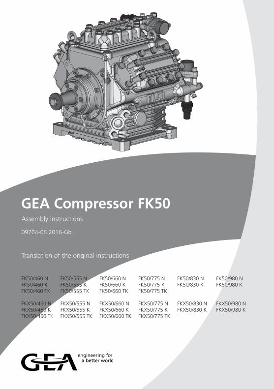
GEA Compressor FK50Assembly instructions
09704-06.2016-Gb
Translation of the original instructions
FK50/460 N FK50/555 N FK50/660 N FK50/775 N FK50/830 N FK50/980 NFK50/460 K FK50/555 K FK50/660 K FK50/775 K FK50/830 K FK50/980 KFK50/460 TK FK50/555 TK FK50/660 TK FK50/775 TK
FKX50/460 N FKX50/555 N FKX50/660 N FKX50/775 N FKX50/830 N FKX50/980 NFKX50/460 K FKX50/555 K FKX50/660 K FKX50/775 K FKX50/830 K FKX50/980 KFKX50/460 TK FKX50/555 TK FKX50/660 TK FKX50/775 TK

2 0970
4-06
.201
6-DG
bFIT
rCn
D
GB
F
I
TR
CN
About these instructionsRead these instructions before assembly and before using the compressor. This will avoid misunderstandings and prevent damage. Improper assembly and use of the compressor can lead to serious or fatal injury. Observe the safety instructions contained in these instructions.These instructions must be passed onto the end customer along with the unit in which the compressor is installed.
GEA Bock GmbH
72636 Frickenhausen
GEA Bock GmbH
Benzstraße 7
72636 Frickenhausen
Germany
Telephone +49 7022 9454 0
Fax +49 7022 9454 137
www.gea.com
Manufacturer
Contact
30970
4-06
.201
6-DG
bFIT
rCn
D
GB
F
I
TR
CN
Contents Page
1 Safety 4 1.1 Identificationofsafetyinstructions 1.2 Qualificationsrequiredofpersonnel 1.3 General safety instructions 1.4 Intended use 2 Product description 6 2.1 Brief description 2.2 Name plate 2.3 Type key 3 Areas of application 8 3.1 Refrigerants 3.2 Oil charge 3.3 Limits of application 3.4 N and K versions 3.4.1 Limits of application R134a 3.4.2 Limits of application R407C 3.5 TK version 3.5.1 Limits of application R404A/R507 3.5.2 Limits of application R22 4 Compressor assembly 11 4.1 Setting up 4.2 Maximum permissible inclination 4.3 V-belt drive 4.4 Main bearing load 4.5 Electromagnetic clutch assembly 4.6 Pipe connections 4.7 Pipes 4.8 Operating the shut-off valves 4.9 Operating mode of the lockable service connections 5 Commissioning 15 5.1 Preparations for start-up 5.2 Pressure strength test 5.3 Leak test 5.4 Evacuation 5.5 Refrigerant charge 5.6 Oil level check 5.7 Shaft seal 5.8 Shaft seal, emptying the oil reservoir 5.9 Avoidingliquidshocks 6 Maintenance 18 6.1 Preparation 6.2 Work to be carried out 6.3 Recommended spare parts 6.4 Integrated decompression valves 6.5 Extract from the lubricants table 6.6 Decommissioning 7 Accessories 20 7.1 Capacity regulator 7.2 Thermi protection thermostat 8 Technical Data 21 9 Dimensions and Connections 22 10 Installationcertificate 24 11 Service 25
4 0970
4-06
.201
6-DG
bFIT
rCn
D
GB
F
I
TR
CN
1.1 Identificationofsafetyinstructions:
DANGER! Indicates a dangerous situation which, if not avoided, will cause
immediate fatal or serious injury.
WARNING! Indicates a dangerous situation which, if not
avoided, may cause fatal or serious injury.
CAUTION! Indicates a dangerous situation which, if not
avoided, may cause fairly severe or minor injury.
ATTENTION! Indicates a situation which, if not
avoided, may cause property damage.
INFO! Important information or tips on simplifying work.
1| Safety
1.2 Qualificationsrequiredofpersonnel
WARNING! Inadequatelyqualifiedpersonnelposestheriskofaccidents,the consequencebeingseriousorfatalinjury.Workoncompressorsis thereforereservedforpersonnelwiththequalificationslisted below: • For example, a refrigeration technician, refrigeration mechatronic engineer. As well as professions with comparable training, which enables personnel to assemble, install, maintain and repair refrigeration and air-conditioning systems. Personnel must be capable of assessing the work to be carried out and recognising any potential dangers.
50970
4-06
.201
6-DG
bFIT
rCn
D
GB
F
I
TR
CN
1| Safety
These assembly instructions describe the standard version of the FK50 manufactured by GEA. The compressor is intended for use in refrigeration systems in compliance with the limits of application. Onlytherefrigerantspecifiedintheseinstructionsmaybeused. Any other use of the compressor is prohibited!
The GEA refrigerating compressor named in the title is intended for installation in a machine (within the EU according to the EU Directives 2006/42/EC Machinery Directive, 97/23/EC Pressure EquipmentDirective).Commissioning is permissible only if the compressor has been installed in accordance with these assembly instructions and the entire system into which it is integrated has been inspected and approved in accordance with legal regulations.
1.4 Intended use
1.3 General safety instructions
DANGER! • Refrigerating compressors are pressurised machines and as such call for heightened caution and care in handling. The maximum permissible overpressure must not be exceeded, even for testing purposes.
WARNING! • Risk of burns! Depending on the operating conditions, surface temperatures of over 60 °C on the discharge side or below 0 °C on the suction side can be reached.
6 0970
4-06
.201
6-DG
bFIT
rCn
D
GB
F
I
TR
CN
2| Product description
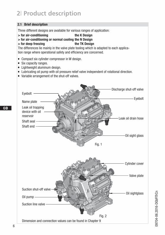
Three different designs are available for various ranges of application:> for air-conditioning the K Design> for air-conditioning or normal cooling the N Design> for deep freezing the TK DesignThe differences lie mainly in the valve plate tooling which is adapted to each applica-tion range where operational safety and efficiency are concerned.
Compact six cylinder compressor in W design. Six capacity ranges. Lightweight aluminum design. Lubricating oil pump with oil pressure relief valve independent of rotational direction. Variable arrangement of the shut-off valves.
Fig. 1
2.1 Brief description
Fig. 2
Valve plate
Cylinder cover
Shaft endShaft seal
Suction shut-off valve
Suction line valve
Oil pump
Dimension and connection values can be found in Chapter 9
Eyebolt
Leak oil trapping device with oil reservoir
Name plate
Eyebolt
Oil sight glass
Oil sightglass
Discharge shut-off valve
Leak oil drain hose
70970
4-06
.201
6-DG
bFIT
rCn
D
GB
F
I
TR
CN
2| Product description
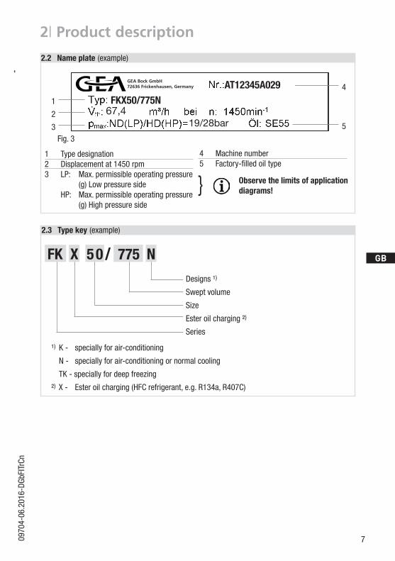
/FK 05 775 NX
1 Type designation2 Displacement at 1450 rpm3 LP: Max. permissible operating pressure (g)Lowpressureside HP: Max. permissible operating pressure (g)Highpressureside
4 Machine number5 Factory-filledoiltype
Fig. 3
2.2 Name plate (example)
2.3 Type key (example)
¹)K - specially for air-conditioning
N - specially for air-conditioning or normal cooling
TK - specially for deep freezing
²)X- Esteroilcharging(HFCrefrigerant,e.g.R134a,R407C)
Designs ¹)
Swept volume
Size
Ester oil charging ²)
Series
1
2
3
4
5
AT12345A029
19/28bar
Observe the limits of applicationdiagrams!}
FKX50/775N67,4
GEA Bock GmbH72636 Frickenhausen, Germany
8 0970
4-06
.201
6-DG
bFIT
rCn
D
GB
F
I
TR
CN
3| Areas of application
ATTENTION! Compressor operation is possible within the limits of application showninthediagrams.Pleasenotethesignificanceofthe shaded areas. The limits of application must be observed. Thresholds should not be selected as design or continuous operating points.
-Max.permissibledischargeendtemperature:140°C -Max.permissibleambienttemperature:100°C -Max.permissibleswitchingfrequency:12x/h -Aminimumrunningtimeof2min.atequilibrium (continuous operation) must be achieved.
Avoid continuous operation near the threshold. Should the compressor happen to be used near the thresholds, we recommend the use of a thermal protection thermostat (Accessories, Chap. 7).
Foroperationwithcapacityregulator: - Continuous operation, when the capacity regulator is activated, is
not permissible and can cause damage to the compressor. - The suction gas superheat temperature may need to be reduced or
set individually when operating near to the threshold. - When the capacity regulator is activated, the gas velocity in the
systemcannotundercertaincircumstancesensurethatsuffici-ent oil is transported back to the compressor.
When operating in the vacuum range, there is a danger of air entering on the suction side. This can cause chemical reactions, a pressure rise in the condenser and an elevated compressed- gas temperature. Prevent the ingress of air at all costs!
Thecompressorsarefactory-filledwiththefollowingoiltype: - for R134a, R404A/R507, R407C FUCHS Reniso Triton SE 55 - for R22 FUCHS Reniso SP 46 Compressorswithesteroilcharge(FUCHSRenisoTritonSE55)aremarkedwithanXinthetypedesignation (e.g. FKX50/775N).
3.1 Refrigerants• HFKW / HFC: R134a, R404A/R507, R407C• (H)FCKW/(H)CFC: R22
3.2 Oil charge
3.3 Limits of application
INFO! Forrecharging,werecommendtheaboveoiltypes.Alternativesare: see lubricants table, Chapter 6.5.
90970
4-06
.201
6-DG
bFIT
rCn
D
GB
F
I
TR
CN
3| Areas of application
Designforotherrangesonrequest
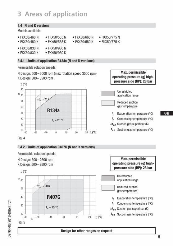
Max. permissible operating pressure (g) high-pressureside(HP):28bar
Max. permissible operating pressure (g) high-pressureside(HP):28bar
Unrestrictedapplication range
Unrestrictedapplication range
Reduced suction gas temperature
Reduced suction gas temperature
Evaporationtemperature(°C)
Evaporationtemperature(°C)
Condensingtemperature(°C)
Condensingtemperature(°C)
Suctiongassuperheat(K)
Suctiongassuperheat(K)
Suctiongastemperature(°C)
Suctiongastemperature(°C)
Fig. 4
Fig. 5
20
30
50
70
80
-20 -10 100 20 30 t (°C)o
t (°C)c
82
-30
40
60
90
t + 25 °Coh
< ? toh 20 K
R134a
20
30
50
-20 -10 100 20 t (°C)o
t (°C)c
61
-30
40
60
-25
< ? toh 20 K
t + 25 °Coh
R407C
3.4.1 Limits of application R134a (N and K versions)
3.4 N and K versionsModels available:
• FKX50/460 N • FKX50/555 N • FKX50/660 N • FKX50/775 N • FKX50/460 K • FKX50/555 K • FKX50/660 K • FKX50/775 K
• FKX50/830 N • FKX50/980 N • FKX50/830 K • FKX50/980 K
Permissible rotation speeds:
N Design: 500 – 3000 rpm (maxrotationspeed3500rpm)K Design: 500 – 3500 rpm
3.4.2 Limits of application R407C (N and K versions)
Permissible rotation speeds:
N Design: 500 – 2600 rpmK Design: 500 – 3500 rpm
10 0970
4-06
.201
6-DG
bFIT
rCn
D
GB
F
I
TR
CN
3| Areas of application
3.5 TK version
Models available: • FK50/460 TK • FK50/555 TK • FK50/660 TK • FK50/775 TK • FKX50/460 TK • FKX50/555 TK • FKX50/660 TK • FKX50/775 TK
3.5.1 Limits of application R404A/R507 (TK version)
3.5.2 Limits of application R22 (TK version)
Permissible rotation speeds:
TK design: 500 – 2600 rpm
Permissible rotation speeds:
TK design: 500 – 2600 rpm
FK
100-10-20-30-40-5020
30
40
50
60
70
t (°C)o
t (°C)c
Dtoh<20K
t +20°Coh
58
-45
R404A/R507
R404A/R507 TK
t c
t 0
toh
Dt oh
Verdampfungstemperatur (°C)
Verflüssigungstemperatur (°C)
Sauggasüberhitzung (K)
Sauggastemperatur (°C)
UneingeschränkterAnwendungsbereich
reduzierte Sauggastemperatur
FK
R22
t c
t 0
toh
Dt oh
Verdampfungstemperatur (°C)
Verflüssigungstemperatur (°C)
Sauggasüberhitzung (K)
Sauggastemperatur (°C)
UneingeschränkterAnwendungsbereich
reduzierte Sauggastemperatur
R22 TK
100-10-20-30-40-5020
30
40
50
60
70
t (°C)o
t (°C)c
Dtoh<20K
t +25°Coh
66
-45
Max. permissible operating pressure (g) high-pressureside(HP):28bar
Unrestrictedapplication range
Reduced suction gas tempera-ture
Evaporationtemperature(°C)
Condensingtemperature(°C)
Suctiongassuperheat(K)
Suctiongastemperature(°C)
Fig. 6
R404A/R507
R22
Max. permissible operating pressure (g) high-pressureside(HP):28bar
Unrestrictedapplication range
Reduced suction gas tempera-ture
Evaporationtemperature(°C)
Condensingtemperature(°C)
Suctiongassuperheat(K)
Suctiongastemperature(°C)
Designforotherrangesonrequest
Fig. 7
110970
4-06
.201
6-DG
bFIT
rCn
D
GB
F
I
TR
CN
4| Compressor assembly
4.1 Setting up
4.2 Maximum permissible inclination
A max. 30°, max. 2 minutes
a max. 15°, continuous operation
ATTENTION! Poor lubrication can damage the compressor. Respect the stated values.
INFO! Newcompressorsarefactory-filledwithinertgas(3barnitrogen). Leave this service charge in the compressor for as long as possible and prevent the ingress of air.
Check the compressor for transport damage before starting any work.
Fig. 8
Transportandsuspensionunitonbotheyebolts(Fig.8).
Fittings(e.g.pipeholders,additionalunitsetc.)onthecompressorarepermissibleonlyfollowing consultation with GEA.
Setuponanevensurfaceorframewithsufficientload-bearingcapacity.Useall4fasteningpoints.
Correct setup of the compressor and mounting of the belt drive are decisive for running comfort, operating safety and the service life of the compressor.
WARNING! Movecompressorsonlywithhoiststhathaveadequateload-bearing capacity.
A Aa a
A Aa a
Fig. 9
12 0970
4-06
.201
6-DG
bFIT
rCn
D
GB
F
I
TR
CN
4| Compressor assembly
Duringoperationwith capacity controllers (Accessories,Chap.7), the changing load can causeincreased running noises and belt drive vibrations.
4.3 V-belt drive
4.5 Electromagnetic clutch assembly
ATTENTION! Inappropriately designed belt drives, especially belt knocking or excessive tensioning forces can cause compressor damage! Make sure that the drive belt is designed correctly, e.g. by using tensionersandselectingthebeltprofileandthebeltlength.
The following description applies for an electromagnetic clutch secured to a shaft. To absorb themagnetic field of the electromagnetic clutch, the front bearing flange has asnugfit148h8(seeFig.11).
Toconnectthemagneticfield,loosenthe4cheeseheadscrewsM8onthebearingflange(seeFig.11).
Slidethemagneticfieldtoasnugfitandre-attachusingthefourcheeseheadscrewsM8(Fig.12).Screwtorque=34Nm.
Further assembly of the electromagnetic clutch according to the clutch manufacturer.
Fig. 11
Bearingflange,front
Magneticfield
Fig. 12148 h8
4.4 Main bearing load
To prevent the belt drive overloading the compressor main bearing, ensure that:
The engagement force applied by the belt tension (centre of shafttaper,seeFig.10)mustnotexceedFmax per.=2750N.
If the force engagement point shifts to the right (see Fig.10, smallpoint),theforceFmax per. reduces as per the following formula:
Fmax per.= 245 kNmm
(90 mm + L1[mm])
Fmax= 2750 NMbmax= 245kNmm
L1 (mm)
Fig. 10
130970
4-06
.201
6-DG
bFIT
rCn
D
GB
F
I
TR
CN
4| Compressor assembly
4.7 Pipes
Pipes and system components must be clean and dry inside and free of scale, swarf and layers of rust and phosphate. Only use air-tight parts.
Lay pipes correctly. Suitable vibration compensators must be provided to prevent pipes being cracked and broken by severe vibrations.
Ensure a proper oil return. Keep pressure losses to an absolute minimum.
The discharge and suction line valves have stepped internal diameters, enabling the use of pipes with standard millimetre and inch dimensions. The depth of pipe insertion will depend on the dimension. The connection diameters of the shut-off valves are designed for
maximum compressor output. Therequiredpipecross-section must be matched to the capacity. The same applies for non-return valves.
Fig. 13: Stepped internal diameters
4.6 Pipe connections
4.8 Operating the shut-off valves
Before opening or closing the shut-off valve, release the valve spindle seal by approx. ¼ of a turn counter-clockwise.
After activating the shut-off valve, re-tighten the adjustable valve spindle seal clockwise.
Fig. 14 Fig. 15
ATTENTION! Overheating can damage the valve. Therefore, remove the pipe supports from the valve before soldering.
Solder only using inert gas to inhibit oxidation products.
Therequiredtighteningtorquefortheflangeconnectionis60Nm.
Valve spindle seal
Release
Tighten
14 0970
4-06
.201
6-DG
bFIT
rCn
D
GB
F
I
TR
CN
4| Compressor assembly
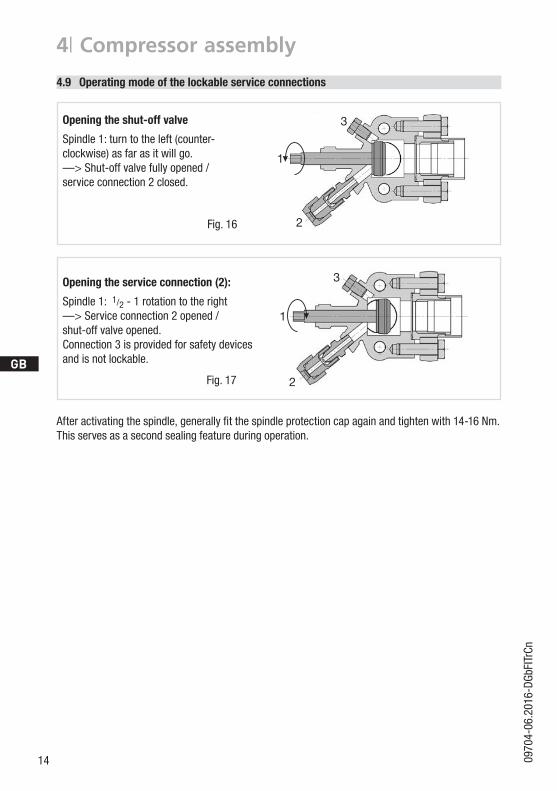
4.9 Operating mode of the lockable service connections
Fig. 16
Fig. 17
Opening the shut-off valve
Spindle 1: turn to the left (counter-clockwise)asfarasitwillgo. —> Shut-off valve fully opened / service connection 2 closed.
Openingtheserviceconnection(2):
Spindle 1: 1/2 - 1 rotation to the right —> Service connection 2 opened / shut-off valve opened.Connection 3 is provided for safety devices and is not lockable.
1
1
3
3
2
2
Afteractivatingthespindle,generallyfitthespindleprotectioncapagainandtightenwith14-16Nm.This serves as a second sealing feature during operation.
150970
4-06
.201
6-DG
bFIT
rCn
D
GB
F
I
TR
CN
5| Commissioning
5.1 Preparations for start-up
5.4 Evacuation
First evacuate the system and then includethe compressor in the evacuation process. Relieve the compressor pressure. Open the suction and discharge line valves. Evacuate the suction and discharge pressure sides using the vacuum pump. At the end of the evacuation process, the vacuum should be < 1.5 mbar when the pump is switched off. Repeattheprocessasoftenasisrequired.
INFO! To protect the compressor against inadmissible operating conditions, high-pressure and low-pressure pressostats are mandatory on the installation side.
The compressor has undergone trials in the factory and all functions have been tested. There are therefore no special running-in instructions.
Check the compressor for transport damage!
5.3 Leak test
Carry out the leak test on the refrigerating plant in accordance with EN 378-2 or a corresponding safety standard, while always observing the maximum permissible overpressure for the compressor.
DANGER Risk of bursting! The compressor must only be pressurised using nitrogen (N2). Never pressurise with oxygen or other gases!The maximum permissible overpressure of the compressor must not be exceeded at any time during the testing process (see name plate data)! Do not mix any refrigerant with the nitrogen as this could cause the ignition limit to shift into the critical range.
5.2 Pressure strength test
The compressor has been tested in the factory for pressure integrity. If however the entire system is to be subjected to a pressure integrity test, this should be carried out in accordance with EN 378-2 or a corresponding safety standard without the inclusion of the compressor.
16 0970
4-06
.201
6-DG
bFIT
rCn
D
GB
F
I
TR
CN
5| Commissioning
CAUTION! Wear personal protective clothing such as goggles and protective gloves!
Make sure that the suction and discharge line valves are open.
Withthecompressorswitchedoff,addtheliquidrefrigerantdirectlytothecondenserorreceiver,breaking the vacuum.
If the refrigerant needs topping up after starting the compressor, it can be topped up in vapour formonthesuctionside,or,takingsuitableprecautions,alsoinliquidformattheinlettotheevaporator.
After starting, check the compressor's oil level. Drive motor in operating condition "High idle". Compressor run time min. 10 minutes. The system should have reached operating points. Checkoillevel.Astheinstallationlocationofthecompressorcandifferinpractice(inclinations),
it is recommended that the oil level is checked in both sightglasses. The oil level must be visible in at least one sightglass.
ATTENTION! Avoidoverfillingthesystemwithrefrigerant! To avoid shifts in concentration, zeotropic refrigerant blends (e.g. R407C) must always be added to the refrigerating plant in liquidform. Donotpourliquidrefrigerantthroughthesuctionlinevalveon the compressor. It is not permissible to mix additives with the oil and refrigerant.
5.5 Refrigerant charge
5.6 Oil level check
5.7 Shaft seal
ATTENTION! Failure to observe the following instructions can cause loss of refrigerant and damage to the shaft seal!
INFO! The shaft seal seals and lubricates with oil. An oil leakage of 0.05 ml per operating hour is therefore normal. This applies particularly during the run-in phase (200 – 300 h). Totrapandcollectleakedoil,theFK50isfittedwithan integrated leak oil trapping device with oil reservoir (P.6, Fig. 1).
ATTENTION! After a compressor is replaced, the oil level must be checked again. If the level is too high, oil must be drained off (risk of oil impact, reduced performance of the air-conditioning system).
170970
4-06
.201
6-DG
bFIT
rCn
D
GB
F
I
TR
CN
5| Commissioning
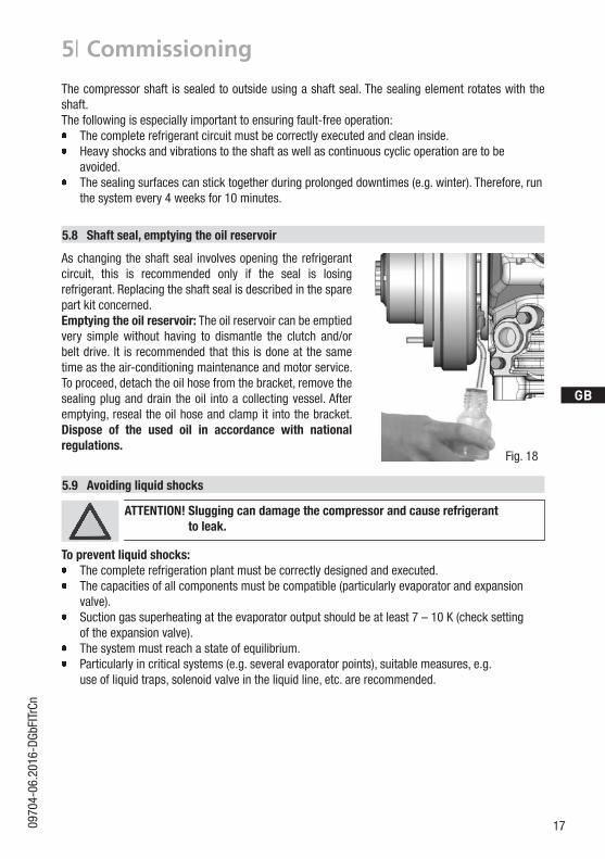
As changing the shaft seal involves opening the refrigerant circuit, this is recommended only if the seal is losing refrigerant. Replacing the shaft seal is described in the spare part kit concerned.Emptyingtheoilreservoir: The oil reservoir can be emptied very simple without having to dismantle the clutch and/or belt drive. It is recommended that this is done at the same time as the air-conditioning maintenance and motor service. To proceed, detach the oil hose from the bracket, remove the sealing plug and drain the oil into a collecting vessel. After emptying, reseal the oil hose and clamp it into the bracket. Dispose of the used oil in accordance with national regulations.
The compressor shaft is sealed to outside using a shaft seal. The sealing element rotates with the shaft. The following is especially important to ensuring fault-free operation: The complete refrigerant circuit must be correctly executed and clean inside. Heavy shocks and vibrations to the shaft as well as continuous cyclic operation are to be
avoided. Thesealingsurfacescansticktogetherduringprolongeddowntimes(e.g.winter).Therefore,run
the system every 4 weeks for 10 minutes.
5.8 Shaft seal, emptying the oil reservoir
5.9 Avoidingliquidshocks
ATTENTION! Slugging can damage the compressor and cause refrigerant to leak.
Topreventliquidshocks: The complete refrigeration plant must be correctly designed and executed. The capacities of all components must be compatible (particularly evaporator and expansion valve). Suction gas superheating at the evaporator output should be at least 7 – 10 K (check setting oftheexpansionvalve). Thesystemmustreachastateofequilibrium. Particularlyincriticalsystems(e.g.severalevaporatorpoints),suitablemeasures,e.g. useofliquidtraps,solenoidvalveintheliquidline,etc.arerecommended.
Fig. 18
18 0970
4-06
.201
6-DG
bFIT
rCn
D
GB
F
I
TR
CN
6.1 Preparation
6.2 Work to be carried out
6| Maintenance
FK50 / ... 460 N, TK555 N, TK
660 N, TK775 N, TK830 N980 N
460 K, 555 K660 K, 775 K830 K, 980 K
Designation Art. No. Art. No. Art. No.
Set of gaskets 80231 80089
Valve plate kit 80243 80244 08926
Set of shaft seals 80023
Oil SP 46, 1 litre 02279
Oil SE 55, 1 litre 02282
Oilchange:In principle, an oil change is not mandatory if the system is correctly manufactured and operated. However, based on decades of experience we recommend that the following oil change/service work is carried out: - Firstoilchangeduringthefirstmaintenanceofthevehicle. - Then after every 5,000 operating hours, though no more than 3 years, clean the oil strainer at the same time. If necessary, also empty the oil reservoir at the shaft seal.
Annualchecks: Oil level, tightness of the compressor, running noise, pressures, temperatures, function of auxiliary devices such as checking the capacity control.
The valves are fundamentally maintenance-free.
However, constant leakage can occur after repeated blowing off due to abnormal operating conditions. This leads to reduced performance and increases the compressed gas temperature. In this case check the valves and replace as necessary.
6.4 Integrated decompression valves
Only use genuine GEA spare parts!
6.3 Recommended spare parts
WARNING! Beforestartinganyworkonthecompressor: Switch off the compressor and secure it to prevent a restart. Relieve compressor of system pressure. Preventairfrominfiltratingthesystem! Aftermaintenancehasbeenperformed: Connect safety switch. Evacuate compressor. Release switch lock.
190970
4-06
.201
6-DG
bFIT
rCn
D
GB
F
I
TR
CN
6.6 Decommissioning
Close the shut-off valve on the compressor. Drain the refrigerant (it must not be discharged directly into the environment) and dispose of it according to the regulations. When the compressor isdepressurised, undo the fastening screws of the shut-off valves. Remove the compressor using an appropriate hoist. Dispose of the oil inside in accordance with the valid national regulations.
6| Maintenance
6.5 Extract from the lubricants table
The oil type charged as standard in the factory is marked on the name plate. This oil type should be used as a preference. Alternatives are stated in the extract from our lubricants table below.
Refrigerants GEA standard oil types Recommended alternatives
HFC(e.g. R134a, R407, R404A)
Fuchs Reniso Triton SE 55(seealsochap.6.3)
Fuchs SEZ 32/68/80Esso/Mobil EAL Arctic 46
HCFC(e.g.R22) Fuchs Reniso SP 46(seealsochap.6.3)
BP Energol LPT 46Sunoco Suniso 3.5GSTexaco Capella WF 46
20 0970
4-06
.201
6-DG
bFIT
rCn
D
GB
F
I
TR
CN
7| Accessories
7.1 Capacity regulation
FK50 / ... ... N + TK ... K
Designation Item No. Item No.
Special accessory 12 V 08703 08708
Special accessory 24 V 08704 08709
Foradescription,seetechnicalinformation"Capacityregulation"(ItemNo.09900)
Ifthecapacityregulatorisfactory-fitted,itisintegratedintoanextra,dedicatedcylindercover.Forretrofits,itissuppliedwiththecylindercover.Theregulatorclosesonecylinderbankatatime(capacityregulationapprox.33%).Tworetrofitkitsarerequiredforacapacityregulationofapprox.66%.
A screw-in option is provided for the sensor element on the hot gas side of the compressor housing(seeChap.9).Connectthethermalprotectionthermostatinserieswiththecontrolline.
Technical Data:
Switching voltage max. : 24 V DC Switching current max. : 2.5 A at 24 V DCSwitch-off temperature : 145 °C ± 5 KSwitch-on temperature : approx. 115 °C
7.2 Thermal protection thermostat (Item No. 07595)
ATTENTION! Capacity-regulated operation alters the gas speeds and pressure ratiosoftherefrigeratingplant:Adjustthesuctionlineroutingand dimensioning accordingly, do not set the control intervals too close and do not let the system switch more than 12 times per hour (refriger-atingplantmusthavereachedastateofequilibrium).Continuousoperation in the control stage is not recommended as the gas velocity in the plant system under certain circumstances does not guaranteesufficientoil return to thecompressorwithactivated capacity regulator for a compressor speed below 1200 - 1500 rpm.
We recommend switching to unregulated operation (100% capacity) for at least 5 minutes per capacity-regulated operating hour. An assuredoilreturncanalsoberealisedbya100%capacityrequire- ment after each compressor restart as otherwise the compressor can also be shut down in the regulated operating time by the thermostat. Electricalactuationofthesolenoidvalve:Normallyopen,(corre-
sponds to 100 % compressor capacity). Cylinder covers for capacity regulation are marked with the
designation "CR" (Capacity Regulator).
210970
4-06
.201
6-DG
bFIT
rCn
D
GB
F
I
TR
CN
8| Technical dataTy
pe
No. of cylinders
Disp
lace
-m
ent
cm3
Swep
t vo
lum
e(1
450 rpm)
m3 /
h
Wei
ght
kg
Disc
harg
e lin
eDV
mm
/ in
ch
Suct
ion
line
SV
mm
/ in
ch
Oil
char
ge
Ltr.
Iner
tia
mom
ent
of th
e dr
ivin
g un
it[k
gm2 ]
Lubr
icat
ion
Oil p
ump
FK50
/460
6
459
40,1
44,0
28 /
1 1
/ 835
/ 1
3/ 8
2,5
0,00
47
Forc
ed
lubr
icat
ion
Rota
tion
dire
ctio
nin
depe
nden
t
FK50
/555
556
48,3
43,0
28 /
1 1
/ 835
/ 1
3/ 8
FK50
/660
662
57,6
42,0
35 /
1 3
/ 82
x 35
/ 1
3/ 8
FK50
/775
776
67,6
41,0
35 /
1 3
/ 82
x 35
/ 1
3/ 8
FK50
/830
831
72,3
43,0
35 /
1 3
/ 82
x 35
/ 1
3/ 8
0,00
56FK
50/9
8097
684
,941
,035
/ 1
3/ 8
2 x
35 /
1 3
/ 8
Conn
ectio
ns
The
tech
nica
l dat
a fo
r the
diff
eren
t des
igns
K, N
and
TK
are
iden
tical
. Th
e co
mpr
esso
r typ
e da
ta th
eref
ore
do n
ot m
entio
n th
ese
addi
tions
.
22 0970
4-06
.201
6-DG
bFIT
rCn
D
GB
F
I
TR
CN
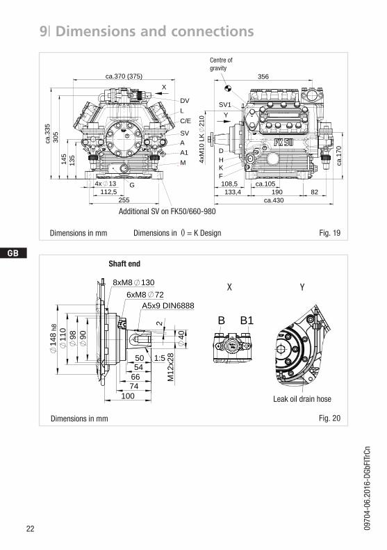
9| Dimensions and connections
Dimensions in ()=KDesign
Shaft end
X Y
Dimensions in mm
Dimensions in mm
Fig. 19
Fig. 20
Leak oil drain hose
ca.1
70
ca.105
4xM
10 L
K21
0
ca.370 (375)
t
0,05 Rz 1,60,30,71,62 Rz 166,3 Rz 63 Rz 6,3Rz 12,5
Abnehmer oder Dritte ist nicht gestattet.
schutz, Verpackung für sicheren Transport).
F
E
D
C
B
A
F
E
D
C
4 3 2 1
A u
678
±0.3
B
5
2345678 1
Zeichn.-Nr. / Drawing no. /Numéro de plan:
Tol.-Ang. DIN ISO 2768-mK
Ra Rz
Neue Modelleinrichtung, Gehäuse wurde optimiertMaß Passung Freigabe
Alternativbezug:Baumustergeprüft
Teil inaktiv
Lieferantenzeichnung
Wir behalten uns alle Rechte, gemäß DIN ISO 16016
-Zeichnung ungültig
Entwicklungsstand
120
Teil keine Serie
PL:K.-Auftrag:
-
w x y z
25
±0.5
über 0.5bis 6
GEA Bock GmbH - Benzstraße 7 - 72636 Frickenhausen - Germany
-
Bau
400
28.10.11--
-
-
Unbemaßte Radien:
an dieser Zeichnung vor.
Bearb.DatumÄnderungs-Nr.
Werkstoff:- -
Ausgangsteil, bzw. Rohteil:
-
Gepr.
Datum Name
28.10.28.10.
DIN ISO 13715
Ersatz für:
Ersetzt durch:
Erstellt2011
Geprüft
1.0851-13863.0 0o CAD
Gneiting
Werkstückkanten
Zone
1/3
Oberflächenbehandlung / Härte:-
Blatt:
Änderungsbeschreibung
Bauknecht
Benennung:
±0.8
1000 30 6 400
-
12030
±0.2
Zeichn.-Nr. Teile-Nr.
Oberflächenangaben ISO 1302
1.0851-13918.0
Zust.
Gußtoleranzen:
Gewicht: (kg)
±0.1
Maßstab:
%
FK50/980 N
Rz 25Rz 160
s
Diese Zeichnung ist unser Eigentum!Sie darf ohne unsere Genehmigung weder nach-gebildet, vervielfältigt, oder Dritten Personen zu-gänglich gemacht werden. Der Nachbau nachdieser Zeichnung, oder an Hand der nach dieserZeichnung hergestellten Gegenstände durch den
Der Lieferant muß sicherstellen, dass die Ware ineinwandfreiem Zustand angeliefert wird (Korrosions-
G:\U
ser\B
aukn
echt
\Pro
jekt
e\FK
50\Z
eich
nung
en\1
3918
-1
721308xM8
6xM8A5x9 DIN6888
1:5 x28
66
100
90
74
110
50
2
54
98 40M
12
148
h8
Y
Lecköl-Ablass SchlauchLeak oil drain hose
Tuyau d'évacuation d'huile de fuite
XB B1
HKF
SV1
D
Y
356
108,5133,4 190 82
ca.430
ZollSight glass 2 x 1 1/8 “ – 18 UNEFK
Raccord de thermostat de protection thermique
Opt. Anschlußmöglichkeit Saugabsperrventil -mm
1) = Nur ab Werk möglich(L)* = Lötanschluß
M22x1,5Bouchon de remplissage d’huile
Anschluß Wärmeschutzthermostat
1) = Only possible ex factory
Oil charge plug
Raccord opt. vanne d'arrêt d'aspiration
Connection thermal protection thermostat
-H
Ölsieb
Schauglas Zoll1/8“ NPTF
Oil filter
Opt. connection oil sump heater 1)
M
(L)* = Raccord à braser1) = Ne possible qu 'ex usine
Opt. connection suction line valveSV1
Opt. Anschlußmöglichkeit Ölsumpfheizung 1)
-M22x1,5
L
Raccord opt. chauffage de carter d'huile 1)
(L)* = Brazing connection
Stopfen Ölfüllung mm-
Voyant
Filtre à huile
Anschlüsse Connections Raccords FK(X)50/460 FK(X)50/555 FK(X)50/660 FK(X)50/775 FK(X)50/830 FK(X)50/980SV Saugabsperrventil, Rohr (L)* Suction line valve, tube (L)* Vanne d’arrêt d’aspiration, de tuyau (L)* mm-Zoll 35 - 1 3/8" 2x35 - 1 3/8"DV Druckabsperrventil, Rohr (L)* Discharge line valve, tube (L)* Vanne d’arrêt de refoulement, de tuyau (L)* mm-Zoll 28 - 1 1/8" 35 - 1 3/8"A Anschluß Saugseite, nicht absperrbar Connection suction side, not lockable Raccord côté aspiration, non obturable Zoll 1/8“ NPTFA1 Anschluß Saugseite, absperrbar Connection suction side, lockable Raccord côté aspiration, obturable Zoll 7/16“ UNFB Anschluß Druckseite, nicht absperrbar Connection discharge side, not lockable Raccord côté refoulement, non obturable Zoll 1/8“ NPTFB1 Anschluß Druckseite, absperrbar Connection discharge side, lockable Raccord côté refoulement, obturable Zoll 7/16“ UNFC Anschluß Öldrucksicherheitsschalter OIL Connection oil pressure safety switch OIL Raccord pressostat de sécurité d’huile OIL Zoll 1/8“ NPTFD Anschluß Öldrucksicherheitsschalter LP Connection oil pressure safety switch LP Raccord pressostat de sécurité d’huile LP Zoll 1/8“ NPTFE Anschluß Öldruckmanometer Connection oil pressure gauge Raccord du manomètre de pression d’huile Zoll 1/8“ NPTFF Ölablaß Oil drain Vidange d’huile Zoll 1/4“ NPTFG
Typ Teile Nr. Typ Teile Nr. Typ Teile Nr. Typ Teile-Nr.FK(X)50/460 N 13863 (13871) * FK(X)50/460 K 13864 (13872) * FK(X)50/830 N 13916 (13923) FK(X)50/460 TK 14347 (14351) *FK(X)50/555 N 13865 (13873) * FK(X)50/555 K 13866 (13874) * FK(X)50/980 N 13918 (13925) FK(X)50/555 TK 14348 (14352) *FK(X)50/660 N 13867 (13875) FK(X)50/660 K 13868 (13876) FK(X)50/830 K 13917 (13924) FK(X)50/660 TK 14349 (14353)FK(X)50/775 N 13869 (13877) FK(X)50/775 K 13870 (13878) FK(X)50/980 K 13919 (13926) FK(X)50/775 TK 14350 (14354)* Keine Serie / No series / Pas de séries
( ) K version( ) K Ausführung
Änderungen vorbehalten
( ) Version K
Sous réserve de toutes modifications
Fahrzeugverdichter / Vehicle Compressor / Compresseur pour automobiles
1.0851-13918.0
Subject to change without notice
MassenschwerpunktCentre of gravityCentre de gravitéMaße in mmDimensions in mmCotes en mm
AA1M
G
SV
DVLC/E
Zusätzliches SV bei FK50/660-980Additional SV on FK50/660-980SV additionel sur FK50/660-980
X
145
ca.3
35
112,5255
305
4x 13
135
Centre of gravity
Additional SV on FK50/660-980
ca.1
70
ca.105
4xM
10 L
K21
0
ca.370 (375)
t
0,05 Rz 1,60,30,71,62 Rz 166,3 Rz 63 Rz 6,3Rz 12,5
Abnehmer oder Dritte ist nicht gestattet.
schutz, Verpackung für sicheren Transport).
F
E
D
C
B
A
F
E
D
C
4 3 2 1
A u
678
±0.3
B
5
2345678 1
Zeichn.-Nr. / Drawing no. /Numéro de plan:
Tol.-Ang. DIN ISO 2768-mK
Ra Rz
Neue Modelleinrichtung, Gehäuse wurde optimiertMaß Passung Freigabe
Alternativbezug:Baumustergeprüft
Teil inaktiv
Lieferantenzeichnung
Wir behalten uns alle Rechte, gemäß DIN ISO 16016
-Zeichnung ungültig
Entwicklungsstand
120
Teil keine Serie
PL:K.-Auftrag:
-
w x y z
25
±0.5
über 0.5bis 6
GEA Bock GmbH - Benzstraße 7 - 72636 Frickenhausen - Germany
-
Bau
400
28.10.11--
-
-
Unbemaßte Radien:
an dieser Zeichnung vor.
Bearb.DatumÄnderungs-Nr.
Werkstoff:- -
Ausgangsteil, bzw. Rohteil:
-
Gepr.
Datum Name
28.10.28.10.
DIN ISO 13715
Ersatz für:
Ersetzt durch:
Erstellt2011
Geprüft
1.0851-13863.0 0o CAD
Gneiting
Werkstückkanten
Zone
1/3
Oberflächenbehandlung / Härte:-
Blatt:
Änderungsbeschreibung
Bauknecht
Benennung:
±0.8
1000 30 6 400
-
12030
±0.2
Zeichn.-Nr. Teile-Nr.
Oberflächenangaben ISO 1302
1.0851-13918.0
Zust.
Gußtoleranzen:
Gewicht: (kg)
±0.1
Maßstab:
%
FK50/980 N
Rz 25Rz 160
s
Diese Zeichnung ist unser Eigentum!Sie darf ohne unsere Genehmigung weder nach-gebildet, vervielfältigt, oder Dritten Personen zu-gänglich gemacht werden. Der Nachbau nachdieser Zeichnung, oder an Hand der nach dieserZeichnung hergestellten Gegenstände durch den
Der Lieferant muß sicherstellen, dass die Ware ineinwandfreiem Zustand angeliefert wird (Korrosions-
G:\U
ser\B
aukn
echt
\Pro
jekt
e\FK
50\Z
eich
nung
en\1
3918
-1
721308xM8
6xM8A5x9 DIN6888
1:5 x28
66
100
90
74
110
50
2
54
98 40M
12
148
h8
Y
Lecköl-Ablass SchlauchLeak oil drain hose
Tuyau d'évacuation d'huile de fuite
XB B1
HKF
SV1
D
Y
356
108,5133,4 190 82
ca.430
ZollSight glass 2 x 1 1/8 “ – 18 UNEFK
Raccord de thermostat de protection thermique
Opt. Anschlußmöglichkeit Saugabsperrventil -mm
1) = Nur ab Werk möglich(L)* = Lötanschluß
M22x1,5Bouchon de remplissage d’huile
Anschluß Wärmeschutzthermostat
1) = Only possible ex factory
Oil charge plug
Raccord opt. vanne d'arrêt d'aspiration
Connection thermal protection thermostat
-H
Ölsieb
Schauglas Zoll1/8“ NPTF
Oil filter
Opt. connection oil sump heater 1)
M
(L)* = Raccord à braser1) = Ne possible qu 'ex usine
Opt. connection suction line valveSV1
Opt. Anschlußmöglichkeit Ölsumpfheizung 1)
-M22x1,5
L
Raccord opt. chauffage de carter d'huile 1)
(L)* = Brazing connection
Stopfen Ölfüllung mm-
Voyant
Filtre à huile
Anschlüsse Connections Raccords FK(X)50/460 FK(X)50/555 FK(X)50/660 FK(X)50/775 FK(X)50/830 FK(X)50/980SV Saugabsperrventil, Rohr (L)* Suction line valve, tube (L)* Vanne d’arrêt d’aspiration, de tuyau (L)* mm-Zoll 35 - 1 3/8" 2x35 - 1 3/8"DV Druckabsperrventil, Rohr (L)* Discharge line valve, tube (L)* Vanne d’arrêt de refoulement, de tuyau (L)* mm-Zoll 28 - 1 1/8" 35 - 1 3/8"A Anschluß Saugseite, nicht absperrbar Connection suction side, not lockable Raccord côté aspiration, non obturable Zoll 1/8“ NPTFA1 Anschluß Saugseite, absperrbar Connection suction side, lockable Raccord côté aspiration, obturable Zoll 7/16“ UNFB Anschluß Druckseite, nicht absperrbar Connection discharge side, not lockable Raccord côté refoulement, non obturable Zoll 1/8“ NPTFB1 Anschluß Druckseite, absperrbar Connection discharge side, lockable Raccord côté refoulement, obturable Zoll 7/16“ UNFC Anschluß Öldrucksicherheitsschalter OIL Connection oil pressure safety switch OIL Raccord pressostat de sécurité d’huile OIL Zoll 1/8“ NPTFD Anschluß Öldrucksicherheitsschalter LP Connection oil pressure safety switch LP Raccord pressostat de sécurité d’huile LP Zoll 1/8“ NPTFE Anschluß Öldruckmanometer Connection oil pressure gauge Raccord du manomètre de pression d’huile Zoll 1/8“ NPTFF Ölablaß Oil drain Vidange d’huile Zoll 1/4“ NPTFG
Typ Teile Nr. Typ Teile Nr. Typ Teile Nr. Typ Teile-Nr.FK(X)50/460 N 13863 (13871) * FK(X)50/460 K 13864 (13872) * FK(X)50/830 N 13916 (13923) FK(X)50/460 TK 14347 (14351) *FK(X)50/555 N 13865 (13873) * FK(X)50/555 K 13866 (13874) * FK(X)50/980 N 13918 (13925) FK(X)50/555 TK 14348 (14352) *FK(X)50/660 N 13867 (13875) FK(X)50/660 K 13868 (13876) FK(X)50/830 K 13917 (13924) FK(X)50/660 TK 14349 (14353)FK(X)50/775 N 13869 (13877) FK(X)50/775 K 13870 (13878) FK(X)50/980 K 13919 (13926) FK(X)50/775 TK 14350 (14354)* Keine Serie / No series / Pas de séries
( ) K version( ) K Ausführung
Änderungen vorbehalten
( ) Version K
Sous réserve de toutes modifications
Fahrzeugverdichter / Vehicle Compressor / Compresseur pour automobiles
1.0851-13918.0
Subject to change without notice
MassenschwerpunktCentre of gravityCentre de gravitéMaße in mmDimensions in mmCotes en mm
AA1M
G
SV
DVLC/E
Zusätzliches SV bei FK50/660-980Additional SV on FK50/660-980SV additionel sur FK50/660-980
X
145
ca.3
35
112,5255
305
4x 13
135
230970
4-06
.201
6-DG
bFIT
rCn
D
GB
F
I
TR
CN
9| Dimensions and connections
SVDV
Suction lineDischarge line see technical data, Chapter 8
A Connection suction side, not lockable 1/8" NPTF
A1 Connection suction side, lockable 7/16" UNF
B Connection discharge side, not lockable 1/8" NPTF
B1 Connection discharge side, lockable 7/16" UNF
C Connection oil pressure safety switch OIL 1/8" NPTF
D Connection oil pressure safety switch LP 1/8" NPTF
E Connection oil pressure gauge 1/8" NPTF
F Oil drain 1/4" NPTF
G Opt. connection for oil sump heater 1)
H Oil charge plug 1/4“ NPTF
K Sight glass 2 x 1 1/8"- 18 UNEF
L Connection thermal protection thermostat 1/8" NPTF
M Oil strainer M22 x 1.5
SV1 Opt. connection for suction line valve - -
1)No connection available as standard. Availableonrequest(ConnectionM22x1.5)
24 0970
4-06
.201
6-DG
bFIT
rCn
D
GB
F
I
TR
CN
10| Installation certificate
INSTALLATION CERTIFICATE
for using the compressors within the European Union(inaccordancewithMachineryDirective2006/42/EC)
The manufacturer: GEA Bock GmbH, Benzstraße 7 D-72636 Frickenhausen, Tel.: 07022/9454-0
hereby declares that the refrigerating compressor FK50conformstotheessentialrequirementsof Annex II 1B of the Machinery Directive 2006/42/EC. Applied harmonised standard:
EN 12693:2008 and the corresponding standards referenced
A partly completed machine may only be put into operation when it has been established that the machine, into which the partly completed machine is to be installed, conforms to the regulationsoftheMachineryDirective(2006/42/EC).
Themanufacturerundertakestotransmitelectronicallythespecialdocumentationrequiredbyindividualstatesforpartlycompletedmachineryuponrequest.
Thespecialtechnicaldocumentationrequiredforpartlycompletedmachineryhasbeencreated in accordance with Annex VII Part B.
Person responsible for documentation is: Wolfgang Sandkötter, Benzstraße 7, 72636 Frickenhausen.
Frickenhausen, 01.11.2011 ppa. Wolfgang Sandkötter, ChiefDevelopmentOfficer
250970
4-06
.201
6-DG
bFIT
rCn
D
GB
F
I
TR
CN
Dear customer,
GEAcompressorsaretop-quality,reliableandservice-friendlyqualityproducts. Ifyouhaveanyquestionsaboutinstallation,operationandaccessories,pleasecontactourtechnicalservice or specialist wholesaler and/or our representative. The GEA service team can be contacted by phone with a toll-free hotline 00 800 / 800 000 88 or via e-mail:[email protected]
Yours faithfully
GEA Bock GmbH
Benzstraße 7
72636 Frickenhausen
Germany
11| Service

We live our values.Excellence • Passion • Integrity • Responsibility • GEA-versity
GEA Bock GmbH
Benzstraße 7
72636 Frickenhausen, Germany
Phone +49 (0)7022 9454-0
Fax +49 (0)7022 9454-137
gea.com
GEA Group is a global engineering company with multi-billion euro sales and operations in more
than 50 countries. Founded in 1881, the company is one of the largest providers of innovative
equipment and process technology. GEA Group is listed in the STOXX® Europe 600 index.