GE Selection and Application Guide for SB Control and ...
77
' GET-6169E • . $electfon and Application Guide for sa:,,pontrol and Transfer Switches - ' \ ) ) - '
Transcript of GE Selection and Application Guide for SB Control and ...

GET-6169E
bull $electfon and Application Guide for sapontrol and Transfer Switches
-
) ) -
Control and Transfer Switches Mulii-siage-1ersaiile-reliable
The SBM Switch - rotary cam-operated compact -for middotpanel mounting only Two electrically separate and mechanically independent contacts per stage These small vershysatile switches mount close and wire easily on your switchboard Common types are warehouse stock
Instruction Book-GEH-2038
Renewal Parts-GEF-4167
The SB-1 Switch -rotary cam-operated slightly larger than the SBM switch and capable of
Instruction Book-GEH-908 more design flexibility Can be indeshyRenewal Parts-GEF-2357pendently mounted and housed Many
common types warehoused
====================================================================================================JI
The SB-9 Switch -a heavier-duty switch than the SB-1-for applications requiring unusually high
Instruction Book-GEH-908numbers of repetitive operations but otherwise similarmiddot in optional features Renewal Parts-GEF-3481
and design capability
The SB-10 Switch -in addition to the rotary operation like the SB-1 switchmiddot the SB-10 is capable
Instruction Book-GEH-908of opening and closing contacts with a
Renewal Parts-GEF-3482lateral push or pull of the handle
The SBE Switch -this switch may not only be manually
Instruction Book-GEK-99289operated locally but may also be electrically
Renewal Parts-GEF-ope~ated remotely
(8919388)
I
I
This publication provides descriptive technical selection and ordering information on control and transfer switches manufactured by General Electric Company
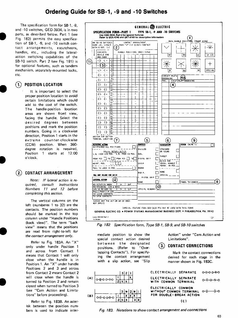
To aid selection and specification general arrangements and contact diagrams are included for the many models of the standard switches described on the opposite page Several standard circuits are illustrated for the common applications such as circuit breaker control and ammeter-voltmeter transfer Select the model which applies and order by model number only using the appropriate ordering guide If the standard switch is satisfactory except for some minor exception specify the exception along with the appropriate catalog number
If a standard model does not meet your application follow the ordering instructions given in this publication to specify the functions you need or order by similar to except (state the exception) Use one of the following forms to place your order
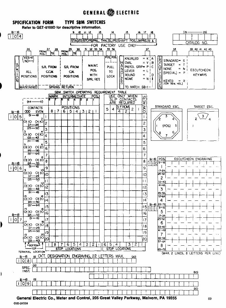
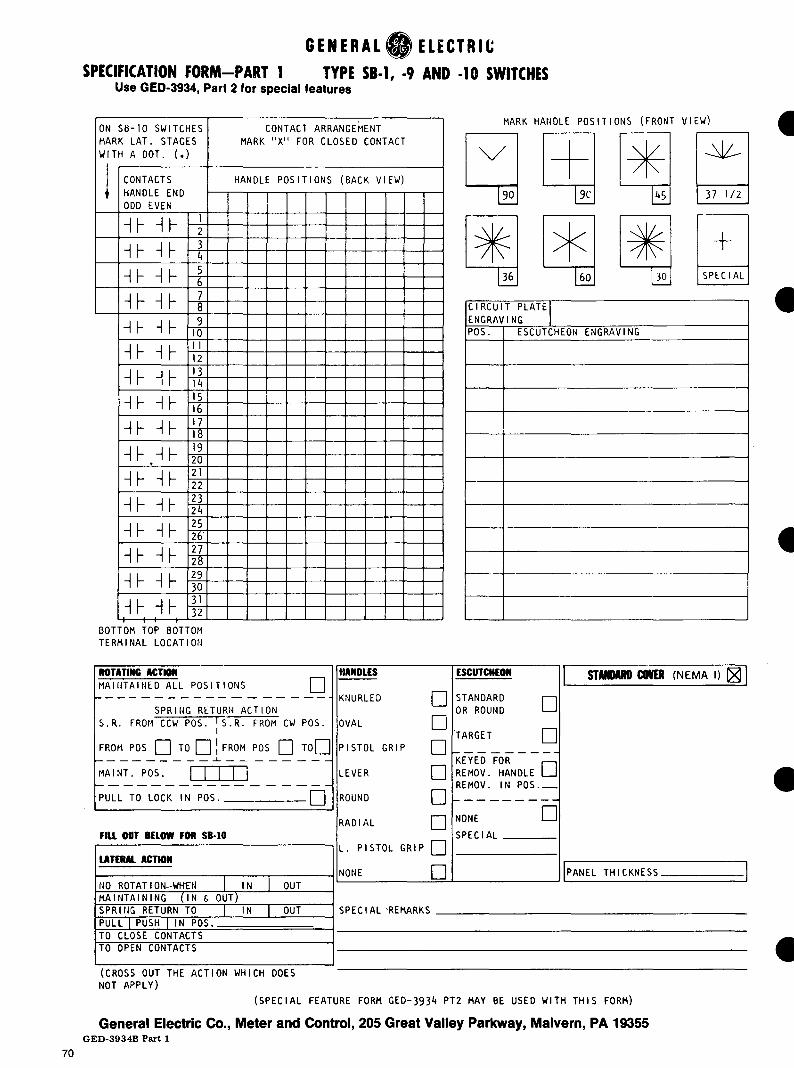
Form GED-3933-for SBM switches only Form GED-3934-for SB-1-9-10 switches
Part 1-Standard features Part 2-Optional features
For convenience copies of these forms have been included in this publication which can be reproduced in lieu of the forms
GE Meter and Control 205 Great Valley Parkway Malvern Pa 19355
Introduction
3
I
PAGE
TYPE SBM SWITCH FEATURES 5 -TYPE SB-1 SWITCH FEATURES 8
OPTIONAL FEATURES-_
SBE ELECTRIC OR HAND OPERATEDCAM ACTION AND LIMITATIONS
OVERLAPPING CONTACTS
REMOVABLE HANDLES
TEMPERATURE METER SWITCHES
OUTLINE DIMENSIONS
TYPE SB-9 SWITCH FEATURES 9
TYPE SB-10 SWITCH FEATURES - middot10
SPECIAL FEATURES SB-1 SB-9 SB-10 middot11
TANDEM SWITCHES 14
PULL-TO-TURN middot 14
PAILADIUM CONTACTS 14
LOCK TYPE SWITCHES _14
(SBM SB-1 SB-9 SB-10) middot16
(SBM SB-1 SB-9 SB-10) middot ~ ~ 18
(SBM SB-1 SB-9) 20
(SB-1) middot- 22
(SBM SB-1 SB-9 SB-10) 23
OUTLINE DIMENSIONS FOR TANDEM SWITCHES 27
OUTLINE DIMENSIONS FOR LOCKED SWITCHES 28
CONTACT DIAGRAMS_FOR SBM SWITCHES 29
CONTACT DIAGRAMS FOR SB-1 SWITCHES 43
ORDERING GUIDE FOR SBM SWITCHES 60
ORDERING GUIDE FOR SB-1-9-10 SWITCHES 63
FORM GED-3933 SPECIFICATION FORM TYPE SBM SWITCHES 69
FORM GED-3934 PART 1 SPECIFICATION FORM SB-1 SWITCHES STANDARD FEATURES 70
FORM GED-3934 PART 2 SPECIFICATION FORM SB-1 SWITCHES SPECIAL FEATURES 71
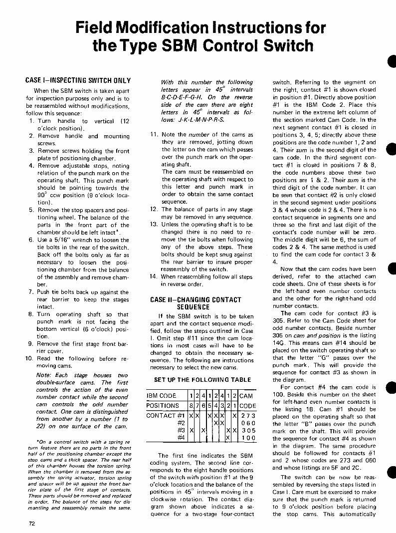
FIELD MODIFICATION INSTRUCTIONS FOR THE TYPE SBM CONTROL SWITCH 72
NOMENCLATURE GUIDE TYPE SBM SWITCHES 74
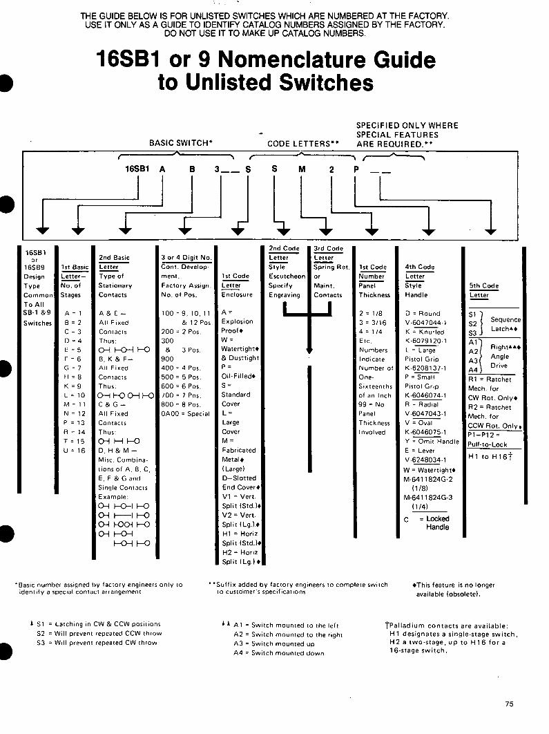
NOMENCLATURE GUIDE TYPE SB-1 AND SB-9 SWITCHES 75
I
4
I Construction Features
Escutcheons Two basic types of escutcheons are available the standard and the target The standard type shown on the left is a molded black phenolic material with white lettering for clear reading of the positions A target type escutcheon shown in the middle is normally furshynished on breaker control switches An aluminum front plate houses the target mechanism with a window in the center to show green for the trip posishytion red for the closed position and black for the pull-to-lock position The
a PISTOL GRIP OVAL
Handles Four types of molded black phenolic handles shaped for easy gripping are available with the SBM switch pistol grip oval knurled and lever Any of the standard handles except the lever may be adapted for removable handle keying A fixed handle may be easily removed for replacement by a screw in the front of the handle A white
KEYED
target has a slip action so that it will remain green when the handle returns to NORMAL from the TRIP position and red when it returns from the CLOSE position This shows the operator the last operation of the switch
On the right a modified standard is shown with keyways for use with a removable type handle
Aluminum circuit designation plates are available for all three types
4KNURLED LEVER
pointer furnished with the handles (except the lever) and mounted near the escutcheon give a clear identishyfication of the position that the handle is in For match and line up with SB-1 switches type SB-1 pistol grip oval knurled and round handles can be furshynished for use with SBM switches
Cams and Contacts The silver to silver contacts of the SBM switch are of double-break design as seen at left which reduces arcing and subsequent pitting of contacts Each contact is operated by a double surface cam one surface for closing the other surface for opening This construction provides opening and closing action not dependent on springs
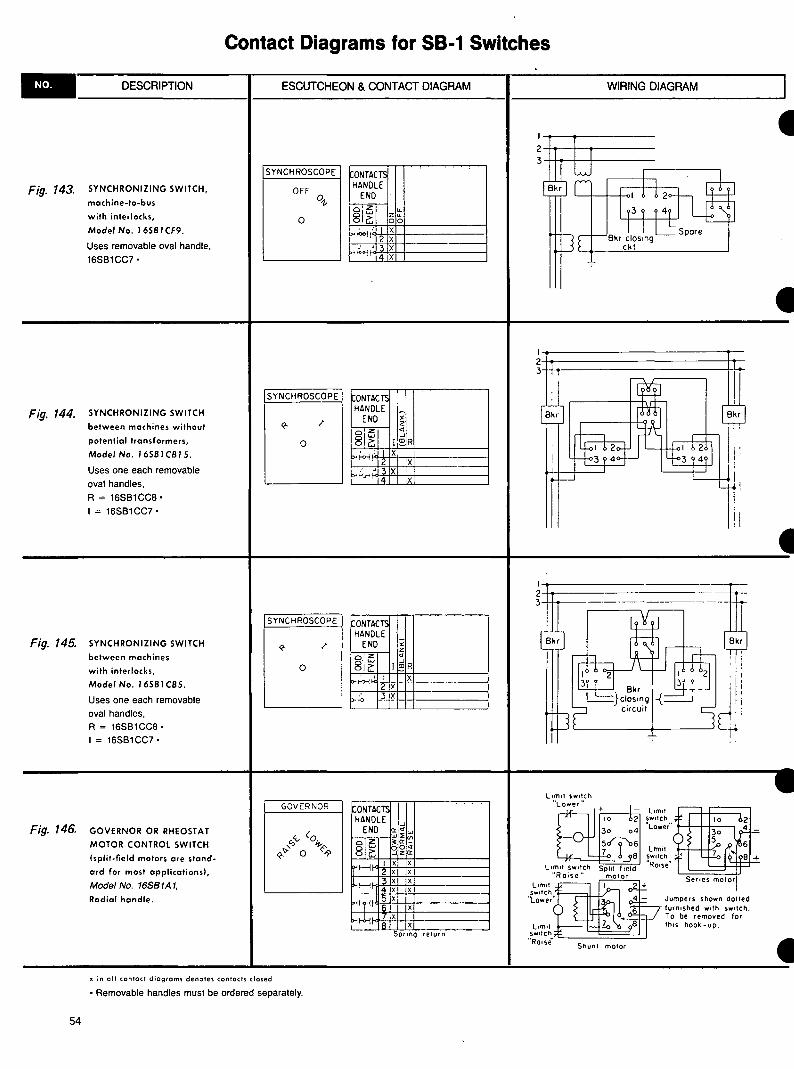
Keyed Escutcheons and Removable Handles -The removable handle commonly used in synshychronizing switches can be made to be reshymoved in any one of the eight positions There are three keys set in front of the handle so that they fit the designated keyways in the escutcshyheon in a desired position The escutcheon can be keyed so that a handle is interchangeshyable or non-interchangeable with another switch If this is desired the catalogue number of the other switch and the position in which the handle is to be removed must be given The removable handle is not furnished with the switch but as a separate item
-Slip Cams The slip cam is basically used on breaker conshytrol switches The slip action enables a contact to remain closed or open after returning to the normal (12 oclock) position from either the CW or CCW positions
I
I
6
I
- Positioning Contacts of the SBM switch are positively positioned by a detent wheel mounted on a square shaft and acted upon by a springshyloaded roller arm If the shaft of the 45deg switch is not rotated more than one-half the distance between positions it will snap back to its prior position If rotated more than half the distance between positions it will snap to the next posishytion The 90deg switch has this same positive detent action when in position but the snapshyping action is not as prominent Up to eight positions are available with 45deg or 90deg between positions
-Terminal Connections Terminal connections are brought to the corners of each stage allowing screw connections to be made over a large angle This angular displacement of connection points allows the switches to be mounted on three-inch centers or less
Jumpers Jumpers are furnished assembled where required on all standard listed switches For special switches or unshylisted switches separate jumpers can be ordered-
-~ 1T)
Jumper Jumper 307V515P1 307V512P1 (Same Stage) (Adjacent
Stage)
Contacts Positions Handle End 3 2 1
1 X
o-t I-ltgt egt-11-ltgt X2
o-tl--0 X3 X
Break-Before-Make Contacts Contacts on SBM switches are normally non-overlapping (break-before-make) This sequence is illustrated above which shows that contact No 1 opens before contact No 2 closes
Another normal function is illustrated by contact No 3 which is shown closed in two adjacent positions When switching between these positions this contact will always remain closed
Spring Action Torsion springs return the switch handle to or towards the 12 oclock or No 3 position The travel of the handle is limited to 90deg to either side of posshyition 3 The switches may be furshynished with spring return both ways or only one way with maintaining action in the opposite direction You can also have spring return from posishytion No 1 (9 oclock) to position No 2 (10 oclock) andor spring return from position No 5 (3 oclock) to position No 4 (2 oclock) with maintained action in the other positions Torsion springs are housed in the rear half of the posishytioning chamber There is no need to modify the chamber to accommodate the springs
Add-A-Stage A one-half inch exentsion is provided on the rear of all switches with one to eight stages This extension enables a maximum of two adshyditional stages to be easily and economically coupled to the existing switch in the event more contacts are required Maximum number of stages including Add-A-Stage unit is 10 (20 contacts)
I I IContacts Handle End
i~IC~ cu tNrt) Oodj I xx xxxx X~inimiddot 2 XXX 3 X xx xxxx~1661 4 xx X
xx xx5 X xx~fl11bull 6X xx
Overlapping Contacts Overlapping contacts (make-before-break) contribute to the versatility of the SBM switch
Typical overlapping contacts are shown on model switch 10AA009 The asterisk () indishycates an intermediate (non-feel) position and shows the contacts overlapping In the 10AA009 when turning from the OFF position to reading position 1 (Phase 1) contact 2 doses at the intermediate position and before contact 1 which remained dosed through the intermediate position opens
Pull-To-Lock A pull-to-lock mechanism is designed for spring-return switches When the handle is turned to the 9 oclock posishytion it can be pulled out and locked in that position When the handle is pushed in the handle spring returns to the normal position This pull-to-lock feature does not actuate contacts but merely prevents the spring return of the handle
7
I Contacts numbered for easy identification
Circuit designation plate is marked for easy identification of switch functions
Good selection handles
Escutcheon plates of pershymanent-finish molded material are neat in appearance and uniform in size
Front aupport spaces body of switch ~ inch from rear of the pane allowing ample room for inaerting leads into the switch
Protective cover (not shown) completely covers all live parts meets NEMA 1 requireshyments for panel mounted switches
Type SB-1 Switch With Cover Removed
SB-1 Switch Provides Flexible Dependable Control for
Electrically-operated Equipment Type SB-1 switches are rotary camshyoperated devices for the control of electrically-operated circuit breakers small motors magnetic switches and similar devices and for the transfer of meters instruments and relays The Type SB-1 switch has molded cams assembled on a square shaft to prevent slipping Rotation of the shaft moves cams directly against contact arms so that positive high pressure results at the contact Contact action is not dependent on springs
Silver-To-Silver Contacts Silver-to-silver contacts operate with
a positive wiping action to provide lowshyresistance current flow Contacts can be removed independently of other switch parts Barriers between adjacenl conshytacts prevent arcing between circuits The switch complete with cover can be obtained with up to 16 stages two electrically separate contacts per stage and for mounting on panels from 1e to 2 thick The panel thickness should be specified when the switch is ordered if it is not the switch will be furnished for mounting on panels up to frac34t thick The SB-1 switch which has a standard insulating cover meets NEMA I requireshyments for panel mounting
Standard Parts Flexibility and low initial cost are the results of standardizing a basically -simple design Standard SB-1 switches are available for most applications For special applications switches can be built from standard parts The long~ wearing cams positive wiping action of silver-to-silver contacts and positive contact opening and closing action all contribute to a switch which is high in quality and will give you many years of dependable service
SB-1 is recognized under the component proshygram of Underwriters Laboratories Inc
I
8
I
Silver-to-siver contacts-opershy Permanent-finish molded es-ate with positive wiping action cutcheon
Contacts numbered identification
for easy Large pistol grip recommended _
handle is
Heavy-duty shunt connections can withstand millions of conshytact operations
Heavy-duty posilionfng wheel is held in place by compresshysion spring to assure positive positioning Type SB-9 Switch with Cover Removed
Removable cover (not shown) encloses all live parts
SB-9 Control Switch Designed for Highly Repetitive Service
-
-
The Type SB-9 switch for heavy-duty service is used where repetitive operashytions run into many thousands per week The SB-9 switch is similar to the SB-1 except that it has a more positive posishytioning device better insulation to ground and more substantial bearings The contact development diagrams for specific applications follow the same general form as for the SB-1
Ratings
Type SB-1 9 amp 10 switches are rated 600 volts 20 amps continuous or 250 amps for three seconds The interruptshying rating depends upon the voltage and character of the circuit and the number of contacts connected in series as
Circuit Volts 1
24 D-c 6
548 D-c
25125 D-c
75250 D-c
25600 D-c
115 A-c 40
220 A-c 25
440 A-c 12
Inductive Circuit Non-Inductive Circuit
Number of Contacts
2 in Series 4 in Series2 In Series 1 4 in Series
Interrupting Rating in Amperes
20 430 30
1540 3 2525
62511 25 2 95
7 1752 8 65
135 15 35 12545
75 24 50
12 25 4050
1225 5 20
1512 104indicated in the table Contacts can be 550 A-c 6 paralleled when current exceeds 20
Values of inductance equal to that of the average trip circuit For circuits having high values ofamps inductance refer application to your General Electric representative for recommendations
SB-1 amp 9 are recognized under the component program of Underwriters Laboratories Inc 9
Removable cover (not shown) Lateral stage contacts open Rotary stages contacts open encloses all live parts and close with push or pull of and close with rotation of
handle handle left or right
Molded escutcheon plate has durable finish and clear markshying
Type SB-1 oSwitch Without Cover
Lateral contacts give SB-10 switch increased versatility
The SB-10 Switch contacts The lateral contacts which The S8-10 switch is similar to the SB-1 provide two electrically separate and switch except for the addition of lateral mechanically independent switches in
Lateral action of SB-10 switch One Lateral Stage
Pull to open contacts 1-2 Maintaining or spring return in or out Pull to close contacts 1-2 Maintaining or spring return in or out
Two Lateral Stages Pull to open contacts 1-4 Maintaining or spring return in or out Pull to close contacts 1-4 Maintaining or spring return in or out Pull to open contacts 1-2 and close 3-4 Maintaining or spring return in or out
Three Lateral Stages Pull to open contacts 1-6 Maintaining or spring return in Pull to close contacts 1-6 Maintaining or spring return out Pull to open contacts 1-4 and close 5-6 Maintaining or spring return in Pull to open contacts 1-2 and close 3-6 Maintaining or spring return out
Four Lateral Stages middot Pull to open contacts 1-8 Maintaining or spring return in
Pull to close contacts 1-8 Maintaining or spring return out Pull to open contacts 1-6 and close 7-8 Maintaining or spring return in Pull to open contacts 1-2 and close 3-8 Maintaining or spring return out Pull to open contacts 1-4 and close 5-8 - Maintaining or spring return in or out
Pull to open denotes the same contact action as push to close Pull to close denotes the same contact action as push to open
-
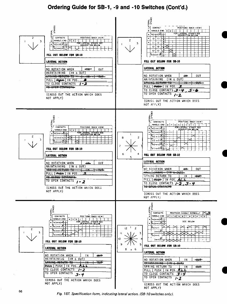
one device are located at the handle end of the switch The lateral contacts operate independently of the rotary I contacts There may be as many as four stages of lateral contacts (two contacts per stage) The lateral action capabilities of SB-10 switches are given in the table The maximum number of stages including rotary contacts is 12 Lateral contacts on the same stage must open and close together There are only two lateral positions IN or OUT Contacts may be closed in either position A spring can be furshynished so that one of the positions is momentary Rotary contacts may have a spring to return the switch to neutral rotary position When a switch is furnished with both lateral and rotary spring reshy -turn the lateral spring can be loaded in the neutral rotary position only Interlocks may be provided so that the lateral action can be made in one or more rotary positions Interlocks may also be provided to prevent rotary action in the IN or OUT positions or to permit rotary action in both the IN or OUT positions The same types of fixed handles and escutcheons used on S8-1 switches may also be used with the SB-10 switches -Drilling dimensions are the same as the SB-1
silver contacts
Barriers between adjacent conshytacts prevents arcing between circuits
10
bull Special Features se-1 9 10
-
-
PositionsA The maximum number of positions is 12B Position locations and throws are availashyC ble as shownD
E F
Handles
A Round 6047044-1 B Oval 6046075-1 C Radial 6047043-1 D Knurled 6079120-1
Handles Seven different types of fixed handles are shown The handles are designed for durability comfortable grip and pleasing appearance An arrow is embedded in the oval and pistol-grip handles for visual aid in positioning A white pointer is furnished with the knurled and round handles To prevent inadvertent operation of equipshyment by unauthorized persons a removable type handle is available for the SB-1 or SB-9 switches The removable handle is keyed to fit the escutcheon in a specific position All but the radial and the lever type handles can be furnished with keyed shanks as removable type handles The handle can be removed in any one or two positions and such positions should be specified when the switch is ordered
Escutcheons The escutcheon is made of molded black phenolic material with white lettering for clear reading of position labels
G
E Large Pistol Grip 6208137-1 F Lever 6248034-1 G Pistol Grip 6046074-1 H Removable Oval
Types of escutcheons 1 The standard type C or E or F above is used when all positions are at the horishyzontal or above 2 The round type A or D above is used when there are positions below the horishyzontal
3 A target-type escutcheon B amp G above normally used on breaker control switches has a red and green target to indicate the last position to which the switch was turned Pull-to-lock target esshycutcheons are shown to the right (Note that maximum throw is 75 degrees counter-clockwise and 45 degrees clockwise)
4 Both the standard and the round type escutcheons can be furnished with keyshyways to interlock with the removable type handles so that the handle is removable only in a specific position
A separate circuit designation plate when furnished is mounted at the top of the escutcheon and is easily removable
2 POSITIONS 90deg APART bull
2 TO 4 POSITIONS 90deg APART 83
2 TO 5 POSITIONS 37 frac120 APART
2 TO 6 POSITIONS 60deg APART
2 TO 8 POSITIONS 45deg APART
2 TO 10 POSITIONS 36deg APART
2 TO 12 POSITIONS 30deg APART
Handle positions
A B
C
11
I Special Features ccoNT)
CLOSING CAM FOR ----H---t----- NO 2 CONTACT
CAM OPERATED CONTACTS
(FIG 10A)
Contacts and Jumpers Rotary contacts on SB-1 9 and 10 switches are normally break-beforeshymake Over-lapping contacts makeshybefore-break) are available and are used basically in ammeter switching applishycations Slip contact operation is availshyable for breaker control application Moving contacts are cam operated for positive opening and closing (Fig 10A) Stationary contacts are assembled on a common support mounted at the top of the switch for easy replacement Three types of stationary contacts are availshyable (Fig 10B)
A Electrlcally common with center binding post which affords single-break single-pole double-throw operation for two electrically common circuits
B Electrically separate Each stage affords single-break single-pole service for two electrically separate circuits
C Electrically common without a center binding post affording two contacts for double-break action Greater switch flexibility can be achieved by use of jumpers (Fig 10C) Four difshyferent types are illustrated When jumpers are ordered with the switch they are supplied unassembled without additional cost They may also be purshychased separately and assembled on existing switches
Spring Return Action
3
Spring return can be adapted to any SB-1 9 and 10 switch providing these limitations are adhered to 1 The handle must return to or toward the 12 oclock position but not pass it 2 The maximum throw is 90deg to either side of the 12 oclock position 3 You cannot have a maintained posishytion pas a spring return position Example if spring return from pos 2 to pos 3 is desired pos 1 cannot be a maintained position However the funcshytional equivalent can be obtained by specifying a pull-to-lock action in place of the maintained position Spring return from both directions to NORMAL or spring return with mainshytained action can be provided on the same switch Example A Spring return from position 1 and 2 to 3 maintaining in positions 3 4 and 5 or spring return from 5 to 4 to 3 maintaining in positions 1 2 and 3
A
B o---U---o o---U--o
C o-lHt--o
(FIG 10B)
atgt flt ~ (SAME STAGE) (ALTERNATE STAGE) 307V512PI 6244177PI
ff Qnnu() 6149141 Pl 1455504PI (ADJACENT STAGE) (FLEXIBLE)
(FIG 10C)
IB A five position switch can be furshynished with partial spring return from positions 1 to 2 and or 5 to 4 with maintaining action in the remaining positions SB-9 only)
Pull-To-Lock A pull-to-lock may be added to lock the switch against spring return action Lockshying is accomplished by pulling the handle out in the pull-to-lock position to engage a latch which arrests the spring return The switch will remain in the locked posshyition until the handle is pushed in Note This pull-to-lock feature does not actuate contacts when pulled
The following are standard pull-to-lock combinations available with a standard target type escutcheon -A Spring return from all positions to NORMAL except when middot locked pull handle to lock at 75deg CCW
B Spring return from 45deg CW and CCW to NORMAL pull to initiate locking at 45deg CCW then turn to 75deg CCW and pull-to-lock
C Spring return from 45deg CW and CCW except when pulled-to-lock at 45deg CCW Special pull-to-lock switches can be I furnished however spring return action from the pull-to-lock position is reshyquired
12
Optional Features se-1 9 10
PullTo-Turn A pull-to-turn feature can be incorporatshyed in a SB-1 or SB-9 switch to prevent accidental operation The handle is locked against turning when it is in the in position and must be pulled out to unlock and turn to the selected positions it is equipped with a lateral spring that pulls the handle to the in position
The handle can be locked against turning in one or more positions or can be free to rotate between certain positions while in the in QOsition
Locks Two different types of locks are availshyable Each allows the switch to be locked in one or more positions One lock is built into the operating handle The other lock is separately mounted on the panel above the switch and when necessary can be coordinated with a Kirk key-interlock scheme When it is necessary to lock switches in more than one position a 45-degree space must be provided between adjashycent locking positions Therefore eight is the maximum number of lock posishytions that can be furnished
Rotary spring action is not recommended with pull-to-turn because the lateral spring may not always overcome the roshytary spring and automatic return to neushytral may not always occur
Push-To-Turn The push-to-turn feature is almost the exact opposite of the above-shown pullshyto-turn feature and the same restriction as to the use of rotary spring return applies
Palladium Cltgtntacts Available for temperature meter switches Palladium contacts have a constant resistance factor which is necessary because calibrated leads are normally used in temperature meter cirshycuits Silver contacts would result in a variable resistance factor and cause fluctuations in meter readings
13
Hand And Electrically Operated Switch Type SBE
~middot-
DESCRIPTION The SBE switch is basically a hand or electrically operarted SB-1 switch The electrical operation is acshycomplished by the use of a high-torshyque vdc motor regulated by the use of an electronic controller and atshytached to the switch by a clutch mechanism
The SB-1 switch portion consists of up to twelve customer-usable silver to silver cam operated contacts with a positive high pressure self-wiping action See Figure 2 for typical conshytact arrangement
The SBE is available for mounting on panels 1 16 to 1 8 thick
APPLICATION SBE switches can be used in place of
the manual-only circuit breaker control switches which can allow remote SCADA supervisory control Even though the SBE switch is longer than the standard SB-1 breaker control switch the panel space for either device is the same Therefore retrofitting manual-only locations with reshymote control is relatively easy
A typical contact wiring diagram is shown in Figure 2 Additional contacts can be used with a white indicating light or alarm to indicate a protective (not operator) trip Also provided are contact to be used with an automatic recloser interlock circuit
This same switch may also be used with different position engraving for opshyeration of motor-operated disconnect switches small motor contactors and similar bi-directional devices The applishycation should be checked for operation with a contact dwell time of 1 second in each direction (CW and CCW) when the SBE is operated electrically
BREAKER CONTROL
D$- middotmiddotmiddot- lto
i middot r-
~ ---
CONTACTS POSITIONS HANDLE
END CLOSE NORMAL AflER CLOSE
NORMAL AFHR TRIP
TRIP
1 2 1 X o--tHI--() 2 X
3 4 3 X X OmiddotH-0 o-H-o 4 X
5 6 5 X X o--l 1-o o--l 1-o 6 X X
Fig 1 SBE switch with cover removed
BURDENS For 125 VDC Motor at 150 VDC
bull 1 amp for 200 ms bull 07 amps for the second dwell period
RATINGS Operating Range of 125 VDC Motor Fig 2 SBE switch
bull 785 to 150 vdc Contact Arrangement
CONTACT RATING -NON-INDUCTIVE CIRCUIT INDUCTIVE CIRCUIT NUMBER OF CONTACTS NUMBER OF CONTACTSCIRCUIT
VOLTS 42 4 2 11 INININ IN
SERIES SERIESSERIES SERIES
300 48 DC
40 20030024 DC 60 250
125 DC 400 30 150025050
95 250 DC
250 20 62511026 65
600 DC 80 07 17520075
125015 035135025 045
500 220 AC
2405004000115 AC 500 2502500 120 400
440 AC 2501200 200 550 AC
50 120 120 15 0600 40 100
The interrupting ratings of the conshy The contacts will carry 20 amps conshytacts vary with the inductance of the cirshy tinuously or 50 amps for 1 minute The cuit The values given above for de inshy contacts will close on 50 amps for volshyductivemiddot circuits are based on the avershy tages 600 volts or less age trip coil currents
14
I
I
(i) ---~--------------r---------------r--------125VOC
CLOSE TRIP 52CS(CW) (CCW)tl_ 52CS C
~ NAC NAT rcsTB Tl3 I 0 TB6
52CSJ_ 52CS 522E0 CIRCUJTC NAC CLOSE CJRCUITS
TBS52 b
PROTECTJVE TRIP ALARM
ANO OR INDICATING
LIGHT
52 a
~ 5CS 52 ~CNAC TC
AUTO RECLDSER INTLK
Fig 3 Typical Control Circuit with SBE (286A3555)
(-) ___j____________j______________________125VOC
15
The operating cam of SB-1 -9 and Cam Action and Limitations -10 switches is based on a 30-degree cut to each side of the center (Fig 1 ) A standard-profile cam will fully open or close a contact in 30 degrees making or breaking 15 degrees from
Fig 1 Operating cam for SB-1 -9 and -10 switches
NO I CONTACT r==== a OR
COMMON OPENING CAM
coR CLOSINGFRONT VIEW HANDLE CAM FOR NQIIN 12OdegCLOCK POSITION CONTACT NOT SHOWN
Fig 2 Composite view of contacts and cams
C B
Fig 3 Individual arrangements of cams in Fig 2
( BACK)POSITIONCONTACTS VIEW HANDLE END
3 2 I
1 I Xo-u--0-11--0 I 2 X X
Fig 4 Contact arrangement back view
the fully open or fully closed position Fig 2 is a composite view of I
contacts and cams assembled on a stage of a switch This figure shows that odd-numbered contacts are on the right side of the switch (viewed from the front) and are closed by the C cam Even-numbered contacts are on the left side and are closed by action of the A cam Both contacts are opened by the B cam
Fig 4 is the contact diagram for Fig 2 with Fig 3 showing the individual arrangement of cams
0 n e cam limitation must be -considered when the switch rotates 180 degrees or more Referring to Fig 3 you see that when cam B is rotated 180 degrees the same relationship occurs between the periphery of Cam B and the contact mechanism of Conshytact No 1 as occurred between the periphery and contact mechanism of Contact No 2 before rotation thereshyfore whatever happens to one contact at any point in the switch rotation must happen to its companion contact in the same stage when the switch is rotated 180 degrees Fig 5 shows the diagram of an unworkable and a I correct arrangement
When contacts on the same stage cannot be arranged to avoid this 180-degree cam limitation one contact per stage is used (See Fig 6) On five-position switches 37-1 2 degrees can be used instead of 45 degrees to avoid this limitation
SLIP CAMS Slip cams increase the flexibility of
the switch They allow a contact to be closed in the NORMAL position after returning from either the CW or CCW position and also to be open in the NORMAL position after returning from the opposite direction This -action is accomplished by allowing the cam to slip 45 degrees as shown in Fig 7 Once the shaft actuates the cam the shaft wil I then slip 45 degrees in the opposite direction without actuating the cam
This type of action is commonly used for circuit-breaker control applishycations Fig 8 shows a breaker conshytrol switch Model 16S8182 which has slip action on Contacts 7 and 8 With this slip action there are some -limitations Three of these limitations and how to avoid them are shown Limitation No 1 does not apply to the SBM switch because of the indepenshydent cams for each contact
16
I
Cam Action and Limitations (Contd) INCORRECT CORRECT
POSITIONS (BACK VIEW) POSITIONS (BACK VIEW) ICONTACTSCONTACTS HANDLE END HANDLE END8 7 6 5 4 2 I3 8 7 5 4 3 2 I6
I 2 o-H-0 0-11--0
3 4 o-n-o o-11--0 5 6ltgtbullHo o-H-o 7 8 o~ o-H-o
Fig 7 Diagram showing
( I NCORRECTl
2 2N IN I
I 2 11 XX o-H--o o-H-o I 2 X X- (CORRECT)
2N IN I2
I I X X o-j l--0----
4
1-ltgt--lkgt 4 X X
Limitation No 1 (SB-1 -9 amp -10)
A slip contact and standard-
I
2
3
4
5
6
7
8 X X
X X
X
Fig 5
I
7
SLIP
STANDARD
X X
5
ESCUTCHEON ( FRONT VIEW)
X
Diagram
3
4
I 2 o-O-o o1-o 3 4 o-H-o o-H-o 5 6o-H-0 o1-o 7 8 o-11-o ~l-0
I
2
3
4
5 6
7 8 X
X
X
X
X
X
X
X
of unworkable and correct arrangement
POSITIONS (BACK VIEW CONTACTS HANDLE END 8 7
ol--0--I
~k)
~l-o-1
1-o-11-0
I
4 X X 5X
8
6 5 4
X
X
X X
3
X
X Fig 6 Contact arrangement to meet cam limitations
CONTACTS HANDLE END
I 2 0-11-0 rH-o
1~4o-1 ~ 5 o-r- __1ry
I~ ao-1 o-j~
I
2 3
4
5
7
8
45-degree slip action of cam Fig 8 Breaker control switch model 16SB182
( INCORRECT l
3 3N
I 2 11 ~1--o o-U-o 12
(CORRECT)
I 2 I )gt-i l-0 0- 2
3~ f--0 0- 4 ) 4
3 3N
X X
2N
X X
2N
X X X X
2
X X
2
X X X X
I
I
X X
2 I
X
X
37
4 5
ESCUTCHEON (FRONT VIEW)
POSITIONS
Close
X
X X
X X
Norm Norm ofter ofter Trip close trip
X X
X X
X X
( INCORRECT)
2
I 2 I I o-n--o o f--0 I2
( CORRECT)
2
I 2 )(jgtmiddotH--0 0
~ 4_I f--0 o-f gt
I 2
3
4
2N
2N
X X
IN
X X
IN
X X X X
I
i X X
Limitation No 2 ( SBMS81 -9 amp -10)
contact On a 4-position pull-to-lock switch tht A contact cannot be closed in the
Limitation No 3 (SBM SB--1 -9 amp -10)
cannot be on the same stage as shown in slip contact cannot be closed in the 2N and normal after position without also closing in the top diagram 2 positions (As shown in the top diagram) the position itself as shown in the top
A stage must be added and contacts split without closing in position 1 To accomplish diagram To accomplish this a stage must be up as shown in the bottom diagram one this a stage is added and the contacts are added and the contacts set up as shown in contact per stage (Does not apply to SBM) connect in series as shown in the bottom the bottom diagram with the contacts
diagram placed in series by jumpers Jumpers required are shipped loose with the switch
17
Overlapping Contacts mediate position is identified by an degrees between positions by use of aGENERAL X in the block above this position in special cam
Contacts on Type SB switches are the operating requirement table ConshySB-1 -9 AND -10 SWITCHESnormally non-overlapping (breakshy tacts 1 and 2 are shown overlapping in
before-make) This sequence is the intermediate Positions 4 and 6 illustrated in Fig 10 which shows that Contact 2 is shown making in intershyContact No 1 opens before Contact mediate Position 4 before Contact 1 No 2 closes when turning from breaks when going from Position 3 Position 1 to Position 2 Another (OFF) to Position 5 (PHASE 1 ) and normal function is illustrated by Contact 1 will make before Contact 2 Contact No 3 which is shown closed breaks when going from Position 5 to in two adjacent positions (Positions 2 Position 7 and 3) When switching between these Figure 12 illustrates an ammeter positions the contact will always switch for three independent current remain closed There are some circuits transformers (similar to Model where this action is not desired such 10AA013) This switch also has overshyas switching current transformers to an lapping contacts and intermediates at ammeter Here the contacts must Positions 2 4 6 and 8 however the overlap (make-before-break) to overlapping action takes place between prevent damaging the meter the intermediate position and the
actual position The X on the lineSBM SWITCH between the positions of thl contacts
To get this overlapping action on identifies this action When turning the contacts 90 degrees between from Position 5 (PHASE I) to Position pos1t1ons is required Figure 11 7 (PHASE 11)Contact 1 makes before illustrates an ammeter switch (similar Contacts 2 and 3 break Also Contact to Model 10AA009) with overlapping 2 and 3 break before Contacts 4 and 5 contacts The overlapping action takes make and Contacts 4 and 5 make place in the intermediate positions before Contact 6 breaks All this (Positions 2 4 6 and 8) The inter- action takes place within the 90
Fg 10 Typical non-overlappingPOSITIONS HANDLE END CONTACTS
(break-before-make) sequence 3 2 I I 2 I Xo-H-o o-H-o 2 X
3 X X~1--o AMMETER
OFF
INTER POSITION
~ 7 IJltI 5 1( 3 I
3
2
AMMETER CONTACTS POSITIONS OFF ODD EVEN 8 7 6 5 4 3 2 I
3 o-U-o o-H--o I
2 X X rx ~ X X -~-
(V 1
2 o-U--ltgt ltgt41--o
3 4 oc
kX
o-11--o ltgt41--o 5 6 x
)( ~
Kx Iv
o-0--o ltgt41--o 7
8 X gtL00 -
~-
o-11--o o-H-o 9 ex
Basically the overlapping action is the same as with the SBM switch but Iit is not limited to positions which are 90-degrees apart
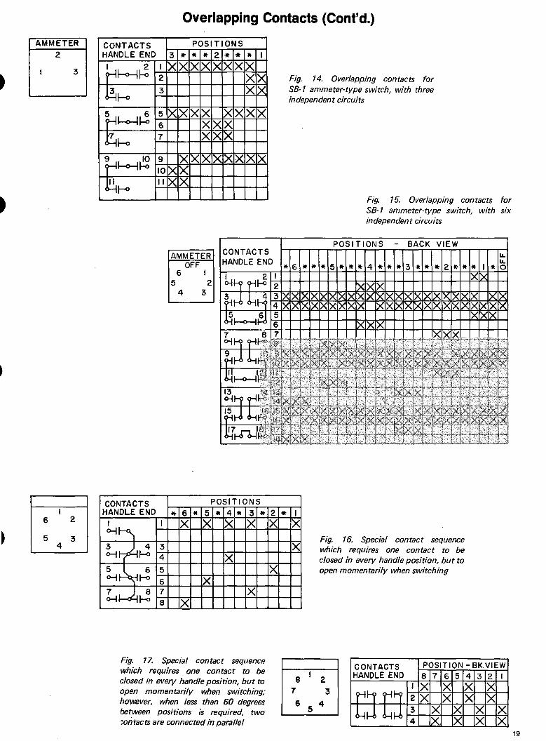
To get a make-before-break action as shown in Fig 13 a minimum of 37frac12 degrees between positions is required To get a make-before-break as shown in Fig 14 a minimum of 60 degrees is required The flexibility of the SB-1 -9 and -10 switch allows the comshybination of 37frac12 degrees and 60 deshygrees in the same switch to give you an ammeter switch which reads as many as six independent current transshy -formers with either 1 or 2 0 F Fs (see Fig 15)
A special contact sequence which requires a contact to close in adjacent positions but to open momentarily between them is shown by Contact 1 in Figure 16 A minimum of 60 degrees between positions is required When less than 60 degrees is required use two contacts in parallel as shown in Fig 17
I INTER POSITION
7531 POSITIONS
ODD EVEN CONTACTS
4 3 2 I
I
8 7 6 5 X XX XX X Xo-11--0 o-H-o 2 XX X
3X XX X XX Xo-H--o o-t f-o 4X XX
sx X X X XX Xo-11--o ltgt41-o 6 X XX
Fig 11 Overlapping contacts for SBM ammeter-type switch connected at end of secondary -
Fig 12 Overlapping contacts for AMMETER POSITIONSCONTACTS SBM ammeter-type switch with three HANDLE ENO Inter Inter I3 22 3 independent circuits I X IX
2 X XX Xt~~ 3 XXH~ 4 X XX X
Fig 13 Overlapping contacts for SB-1 ammeter-type switch 18 connected at end of secondary (two current transformers)
2
Overlapping Contacts (Contd)
AMMETER CONTACTS HANDLE END
3 ~hgt--4~
~1--o
~~~ ~~
~hgt--4~
~rltgt
CONTACTS HANDLE END
6 2 I o-H-~
5 3 4
3~ 40- 1-o
51~ 6o-j rltgt
7 ~ 8 ~ I-ltgt
I
2
3
5
6 7
9 10
II
I
3 4
5
6 7 8
3
X
X
X X
6 5
4
6 X
X
POSITIONS
X X
XX
X X X
X
X
X X X
X
AMMETER OFF
I 2
3
2
X
X X
X
X
X X X
X
XX X X
X X
XX
I
X X
X
X
CONTACTS HANDLE END
POSITIONS
5 X
X
4
X
X
3 X
X
2 X
X
Fig 14 Overlapping contacts for SB-1 ammeter-type switch with three independent circuits
I X
X
Fig 15 Overlapping contacts for SB-1 ammeter-type switch with six independent circuits
POSITIONS - BACK VIEW u
u 0
Fig 16 Special contact sequence which requires one contact to be closed in every handle position but to open momentarily when switching
Fig 17 Special contact sequence POSITION - BKVIEWCONTACTSwhich requires one contact to be
HANDLE END 876543218 2closed in every handle position but to IX XX X7 3open momentarily when switching 2X XX Xhowever when less than 60 degrees 6 4
5 X X X Xbetween positions is required two ~ontacts are connected in parallel X X X
19
To prevent operation ofequipment by unauthorized persons switches with removable handles are available The handle is keyed to a specific escutcheon to be inserted and reshymoved in a designated pos1t1on Handles can also be mutually keyed to other escutcheons so that they are either interchangeable or non-intershychangeable with other switches
This feature is available for SBM SB-1 and SB-9 switches but ordering procedures differ
SBM SWITCHES
0 3 0
5I 0 6 0 7 0
Fig 18 SBM switch keyed escutchshyeon with eight available keyway locashytions Keyways 1-3-5 are shown
The keyed escutcheon on the SBM switch ( Fig 18) has eight possible keyway locations Three are normally used and are assigned by the factory The choice is influenced by several factors
a If the handle is to be intershychangeable with that of another switch the position in which each handle is to be removeable must be considered
b If the handle is to be non-intershychangeable the keyways assigned to other removeable handles in the same panel must be considered
c If no special instruction is given by the customer when he orders the factory will assign keyways at random if more than one SBM switch has a removable handle they will be keyed to be non-interchangeable
A removable handle is furnished as a separate item not with the switch it operates because in some cases the single handle operates many switches The handle is keyed so that it will fit through the keyways on the escutcheon in a specific position
When ordering a removable handle specify the type the position in which it is to be removable and the switch or switches it will be used with The factory will assign the handle To
Removable Handles TABLE 1 Nomenclature guide for SBM removable handles
1st 2nd 5th Number 1st 2nd 3rd 4th
Letter LetterNumber NoNo No
Action ofRemovable Common Escutcheon Type Handle
Rotation Keywaysin Position Code
W=CWampCCW 11 = Knurled 1 w 1 1
L = CCW (special) thru thru thru2 = Oval thru
R = CW (special) 8 grip
3 = Pistol 8 88
Example 1 21WW135
This oval handle has keys at positioos which when it is in position 1 or nine oclock will line up with escutcheon keyways 1 3 and 5 It is therefore removable in position 1
identify SBM removable handles see Table 1
SB-1 amp SB-9 SWITCH
The keyed escutcheon for the SB-1 amp
SB-9 switch is normally furnished with two keys and three keyways (see Fig 19) The circumferential location of the keys and keyways will vary depending on the location etc in which the handle is to be removable The location of the keyways is assigned by the factory
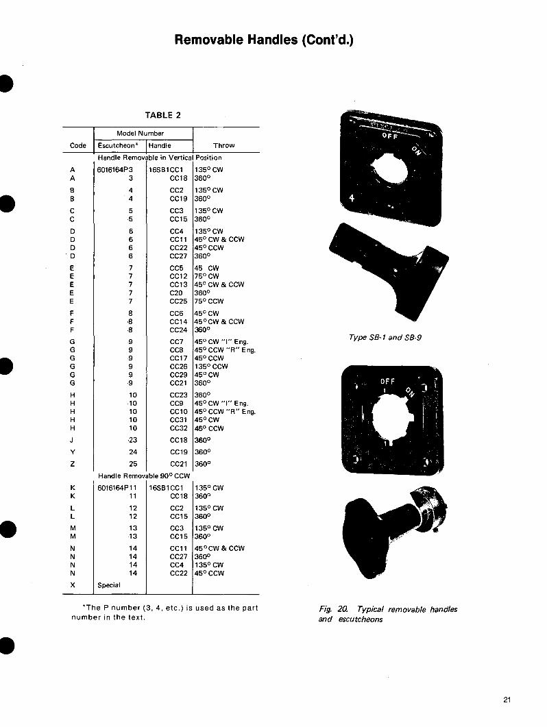
Table 2 gives a list of standard keyed escutcheons and the proper removable handle for removing the handle in both the vertical ( 12 oclock) position and 90deg ccw (9 oclock) pos1t1on Escutcheons 6016164P-2 thru P-14 are used on switches if the throw does not exceed 90deg on either side of the vertical ( 12 oclock) position and P-23 24 and 25 are used when the throw does exceed this limit
0
Fig 19 SB-1 escutcheon for use with removable handle
-
-Oval handles 16S81CC1 thru 32 are
listed with direction and degree of throw from the positions in which they are removable The code letters A thru Z in the left hand column identify the escutcheons used on the basic unlisted switches
I Example 16S81AB300S~M3Y the 2nd form letter ~ identifies a keyed escutcheon 6016164P 3
When a special keyed escutcheon is required different from any of those listed the code letter X is used followed by the part number
Example 16S81AB300SX34M2Y
All keyed escutcheons will now have the part number stamped at the bottom left hand corner instead of the code letters previously stamped at the bottom righthand corner If the code letter or other indentification is deshy -sired it will be stamped at the bottom righthand corner by requisition only (three characters maximum) The 16S81CC oval type removable handle will now have the form number only stamped on the lower face of the handle Those removable handles which have metal shanks (6119745G) will have the group number stamped on the shank When a switch with a Ikeyed escutcheon for a removable handle is ordered be sure to specify the position in which the handle is to be removable If an existing handle will be used give the number of the existing handle
20
Removable Handles (Contd)
I TABLE 2
Model Number
Code Escutcheonbull Handle Throw
Handle Removable in Vertical Position
I
A 6016164P3 16S81CC1 A 3 CC18
B 4 CC2 4 CC19
C
B
5 CC3 5 CC15
D
C
6 CC4 D 6 CC11 D 6 CC22 D 6 CC27
E 7 CC5 7 CC12E
E 7 CC13 7E C20 7E CC25
F 8 CC6 F -8 CC14 F CC248
CC7G 9 G 9 CC8
CC17G 9 G 9 CC26 G 9 CC29
9 CC21
H
G
10 CC23 H 10 CC9 H 10 CC10
10H CC31 10H CC32
J 23 CC18
y 24 CC19
z 25 CC21
Handle Removable 90deg CCW
K 6016164P11 16S81CC1 K 11 CC18
L 12 CC2 12L CC15
M 13 CC3 13M CC15
N 14 CC11 N 14 CC27
14N CC4 14N CC22
SpecialX
135deg cw 360deg
135deg cw 360deg
135degCW 360deg
135deg cw 45degCW amp ccw 45degCCW 360deg
45 cw 75degCW 45degCWamp ccw 360deg 75degCCW
45degCW 45degcw amp ccw 36QO
Type SB-1 and SB-945deg CW I Eng 45deg CCW R Eng 45degccw 135deg CCW 45degCW 360deg OFF
360deg 45deg CW I Eng 45deg CCW R Eng
1
)j~bullbullo+ 45degCW 45deg ccw
I 360deg
360deg
360deg
135degCW 360deg
135degCW 360deg
135deg cw 360deg
45degCW amp ccw 360deg 135deg cw 45degCCW
The P number (3 4 etc) is used as the part Fig 20 Typical removable handles number in the text and escutcheons
21
I
Temperature-Meter Switches
Temperature-meter switches are Fig 21 shows a temperature-meter circuit with a TEST and an OFF furnished with palladium contacts switch Model 16SB 1 CE52 reading position On a three-wire circuit you which have a constant resistance factor This is necessary because calibrated leads are normally used in a temperature-meter circuit and silver contacts would result in a variable resistance factor and cause fluctuation in meter readings
TEST METER Off ~
~ jQr
Ii-2
four RTDs on a two-wire circuit with a TEST and an OFF position On a two-wire circuit you can transfer up to seven coils with an OFF position or six coils with a TEST and an OFF position
Fig 22 shows a Model 16SB1CE55 reading three RTDs
TEMPERATURE METER TRANSFER SWITCH
TRANSFERS TWO WI RES TO FOUR COILS WITH TEST a OFF
MODEL NO 16SBICE52
POSITIONSCONTACTS HANDLE END GI Ill =-C
I-4 i ICs co~ 2~ -
I I X o~ ~~ 2 X
43 3 X XX l-0~ r - 4 X X X
55 Xo-H-~ 6
6-- 1-o X 7 X X X1~LJ 8l-0o-1 r 8 X X X
~ 9 XI 109 II - 1-o 10 X II X X XI 12II
o-i - ~ 12 X XX 115 V A-C SOURCE
X y
FUSES
TEST RESISTOR
C B
4 3 2 DETECTOR COILS IN MACHINE
Fig 21 Temperature meter switch Model 16S81CE52
on a three-wire
TEST METER Off ~
~
can transfer up to six coils with an OFF position or five coils with a TEST and an OFF position When it is required to transfer more RTDs than the maximum for a given switch two switches with a removable handle may be used
TEMPERATURE METER TRANSFER SWITCH
TRANSFERS THREE WIRES TO THREE COILS WITH TEST 8 OFF
MODEL NO 16SBICE55
POSITIONSCONTACTS - 3
- Ill
pound CU
0HANDLE ENO - iC 2 c cl C Ci i I 2 I X 0-1-0-11-0 2 X 3 4 3 X X X 0-l-0-if-0 4 X XX 5 6 5 XX X ltgt-it-o-lrO 6 XX X 7 8 7 Xo-H-ltgt-Hmiddoto 8 X 9 10 9 X XX o-l~r-6 10 X X X II 12 II XX Xo-lkgt-1~ 12 X XX
115 V A-C SOURCE X y
FUSES
TEST RESISTOR
C
3 2 I DETECTOR COILS IN MACHINE
Fig 22 Temperature meter switch Model 16S81CE55
I
22
Outline Dimensions Type SBM Control and Transfer Switches
Hgndi11
li7bull
1-8
Standard ____ Oval SwitchNoof
Stages A B
gbull2
16 1 31 21e 2 4frac12 2v 3 51e 21e
4 51 2v 5 6frac34 2v 6 7 21a
7 7 2v 8 8frac14 21 9 8frac12 2v
10 91a 2v
Knurled
f28
Lever
SHIPPING WEIGHTS
When panel is 1bullthick -add l2to A and B dimensions
Pull-to-Lock Removable Switch Handle Switch
A B A BI I
4) 211 4frac34 3) SJ 27e 5o 3) 5frac34 21a 6 3)
6 271 65a 3) 7) 21 7frac14 3) 7frac126 21o 77e 3)
8) 211 8frac12 3) 8) 21o 91 3) 8frac34 211 91 9) 9 211 9frac34 3)
Approx weights are listed below All weights listed apply to SB switches consisting of one stage Add 6 ounces for each additional stage
Type SBM (1 Stage) 1frac12 lb
(This data is subject to change without notice)
23
---- --- --- --- ---
Outline Dimensions ccoNTgt
Type SB-1 Control and Transfer Switches
(For estimating only) Panel
311
~lt-- Handles 1321--t 1 f-- frac12 drill (3 holes)
T ~~cutcheonmiddotf -~-middot- l--r11
3_] aI 132
-A-_j - 8 -- To1
I Oval I
I I
I I
No of
Stages
Radial
Round 12-8
Ti 1 514 2s 6
7
B
9
10
11
12
13 Locked
14handle
4 15
16
remove cover
SB-1 switch with fixed handles (Outline 116A 130)
Dimension in Inches
Standard Cover
Standard Cover 12 Wires Out Top
and 24 Wires Out Bottom
A I B
5 1316 10116
11 16 20 156
11 136 22 716
13 frac126 25 76
14 1316 28 76
I C
4 frac12
Lorge Cover
Large Cover 24 Wires Out Top
and Bottom
6 116 10 116
4 1116
10 916 19 1116
11frac126 21 316
For spring-return switches when more than three and less than seven contacts close in the normal handle position add frac34 to A and 1frac12 to B When seven or more contacts close in the normal handle position add 1frac12 to A and 3 to B
Note Removable handles are similar to fixed handles and availshyable in all styles except radial and locked They do not alter switch dimensions or panel drilling
SHIPPING WEIGHTS Approx weights are listed below All weights listed apply to SB-1 switches consisting of one stage Add 6 ounces for each additional stage
Type SB-1 (1 Stage) 2 lb (This data is subject to change without notice)
I
I
24
-----
-----
----------
-----
-----
------
-----
---------
---------
---
---
------
---
---
---
---
---
------
------
---
---
---
---
---------------------
---
I
-
No of Stages
I 1
2
3
4
5
6
7
8
9
10
11
12
13
14
15
16-
Outline Dimensions ccoNT)
Type SB-9 Control and Transfer Switches
(For estimating only)
Panel-mounted Type SB-9 switch (Outline 116A139)
PANEL-MOUNTED TYPE SB-9 Dimension ir Inches
Standard Cover 12 Wires out Top and 24 Wires out Bottom
A 8 CI I
41a
51a
61a
71 -~--
71
81a
91a
101a
101e
111a
121a
131a
131e
141a
151o
161
83a
91a
111a
121
141
151e
171
181a
201a
middot211a
231a
241e
261
271e
291a
301e
4frac12
Lorge Cover 24 Wires out
Top and Bottom
A 8 CI I
51a
51
61a
71
81a
81a
91a
10
111a
111e
121a
131a
141a
141e
151a
16 lo
8frac14
101
111a
131a
14frac14
161
17frac14
191a 4l5Ji6
201a
221a
23frac14
251
261a
281a
291a
311a
For spring-return switches when more than three and less than seven contacts close in the normal handle position add frac34 to A and 1frac12 to B When seven or more contacts close in the normal handle position add 1frac12 to A and 3 to B
Note Removable handles are similar to fixed handles and availshyable in all styles except radial and locked They do not alter switch dimensions or panel drilling
SHIPPING WEIGHTS Approx weights are listed below All weights listed apply to SB-9
- switches consisting of one stage Add 6 ounces for each additional stage
Type SB-9 (1 Stage) 3 lb
25
-----
------
----------------
I Outline Dimensions ccoNT)
Type SB-10 Control and Transfer Switches
(For estimating only)
Panel
bull ICx2 16 wide
11or8
n3
-----A----- Panel Ori I ling ---B to Remove Cover (front view)
No of Stoges
1
2t
3t
4t
5
6
7
8
9
10
11
12
Panel-mounted Type SBmiddot10 switch
Dimension in Inches
Standard Cover Large Cover
A B C A B CI I I I I 6frac34
6frac34
7frac12
8frac14
9
9frac34
10frac12
11frac14
12
12frac34
13frac12
Ufrac14
12frac12
12frac12
14
15frac12
17
18frac12
20
21frac12
23
24frac12
26
27frac12
4frac12
12frac347
7 12frac34
7frac34 14frac14
8frac12 15frac34
9frac14 17frac14
10 18frac34 4 15i6
10frac34 20frac14
11frac12 21frac34
12frac14 23frac14
13 24frac34
13frac34 26frac14
14frac12 27frac34
bull Includes both lateral and rotary stages
(Outline 0l65A6122)
SHIPPING WEIGHTS Approx weights are listed below All weights listed apply to Type SB-10 switches consisting of one stage Add 6 ounces for each additional stage
Type SB-10 (1 Stage) 3frac12 lb
(This data is subject to change without notice)
I
I 26
I
-
- ADD 14 TO A amp B DIM
FOR LARGE COVER
NOOF STAGES A B
1 5-116 7-7 16
2 5-1316 8-1516
3 6-916 10-716 - 4 7-516 11-1516
5 8-1 16 13-716
6 8-1316 14-1516
7 9-916 16-716
8 10-516 17-1516
9 11-1 16 19-716
10 11-1316 20-1516
11 12-916 22-716
12 13-516 23-1516
13 14-116 25-716
14 14-1316 26-1516- 15 15-916 28-716
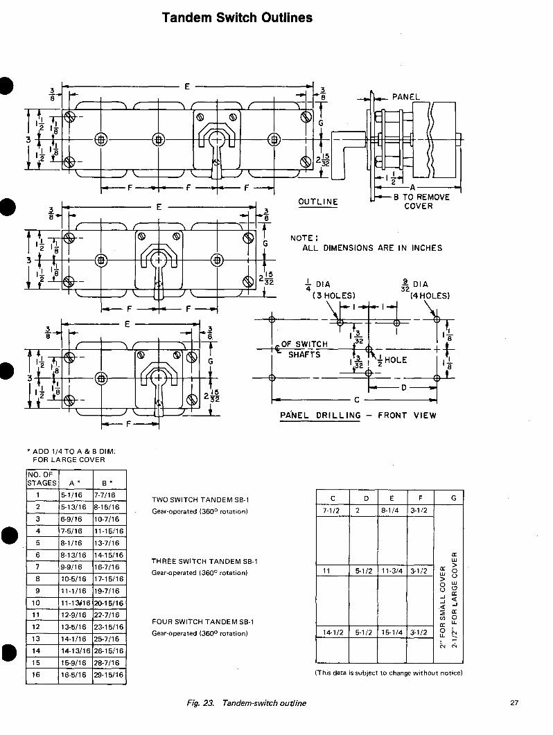
Tandem Switch Outlines
PANEL
frac121 il 11 F--~--F-----F ----A~
B TO REMOVEOUTLINE COVER
NOTE ALL DIMENSIONS ARE IN INCHES
i---------c-------i PANEL
TWO SWITCH TANDEM SB-1
Gear-operated (360deg rotation)
THREE SWITCH TANDEM SB-1
Gear-operated (360deg rotation)
FOUR SWITCH TANDEM SB-1
Gear-operated (360deg rotation)
DRILLING -
C
7-12
11
14-1 2
D
2
5-12
5-1 2
FRONT
E
8-14
11-34
15-1 4
VIEW
F G
3-1 2
a w gta3-12 0w ugt w0 ()u aI ltI Ilt a~
() 0 ua
03-1 2 u ~
N
(This data is subject to change without notice)16 16-516 29-1516
Fig 23 Tandem-switch outline 27
Outline Dimensions for Locked Handle Switches
3116 DI A--- + -r--------
~ 1gttl~1
f DIA--1-4-----fyen-l 3
t 32-rDIA(3l___ PANEL DRILLING (FRONT VIEW)
l middotcbullx2 1
16
WIDE
t~omiddot--1 32 FOR frac14-ifrac14 PANEL
~ FOR I a 2 PANEL
~ FOR 1-t PA~~~-----~
~18
11 TO REMOVE COVER
SB-switch with Yale Lock above the switch ForA and B use standard dimensions plus D depending on panel thickness
SB-9 SWITCHES
STANDARD DIMENSIONS IN INCHES
STANDARD COVER 12 WIRES OUT TOP LARGE COVER
NOOF AND 24WIRES 24WIRES OUT STAGES OUT BOTTOM TOP AND BOTTOM
A B C A B C
1 4-78 8-38 5middot18 8-58
2 5-58 9middot78 5middot78 10middot18
3 6-38 11-38 6-58 11-58
4 7-18 12-78 7middot38 13middot18
5 7-78 14-38 8-18 14-58
6 8-38 15-78 8middot78 16middot1 8
7 9-38 17-38 9-58 17-58
8 10-1 8 18-78 10-38 19middot1 8 4 12 4 15169 10-78 20-38 11-18 20-58
10 11-58 21-78 11-78 22-18
11 12-38 22-38 12-58 23-58
12 13-1 8 24middot78 13middot38 25-1 8
13 13-78 26-38 14middot1 8 2amp58
14 14-58 27-78 14-78 28-1 8
15 15-38 29-38 15middot58 29-58-16 16-18 30middot78 16middot38 31-18
(This data is subject to change without notice)
28 Fig 24 Dimensions control switches with Yale or Kirk Lock
I
Contact Diagrams for SBM Switch
-I VOLTMETER Source Voltmeter
POSITIONS Fig 25 VOLTMETER SWITCH OFF
0-idouble-pole single-throw ON OFF0Model No IOAAOOI 2X
XKnurled handle
VoltmeterVOLTMETER ~ONTACTI POSITIONSHANDLE - OFF ENDFig 26 VOLTMETER SWITCH ltgt I-
0 double-pole double-throw
2 l5 I ~cModel No 10AA002 2
ltgtl~fo I X 2 XKnurled handle
3 43 Xltgtl~fo14 X
VOLTMETER ONTACTI POSITIONSFig 27 VOLTMETER TRANSFER HANDLE N 3 2 I2 ENDSWITCH three-phase
J -transfers lour wires -shy 8Jffic 3 2 lo- 0
I phase-to-neutral 0 IXltgt1tpifo I XModel No 10AA003
3 Xltgtl~ltgtifoKnurled handle 14 IY IX
VOLTMETER tONTACT5 HANDLEFig 28 VOLTMETER SWITCH
END1 2-3
JPhase-to-phase or _ N-cjffi-phase-to-neutral l)N - Move this-08 c0- jumper0 I X IXModeNo 10AA004 3-phose 3-wirP to 1-2 whenrot xx
connectingKnurled handle 3 X switch 3 ltjgt4w~~ 4 X 3-phose 4-wire (future
alternate connection)
Ivo mete I VOLTMETER ~ONTACTI
HANDLE 4 3 2 I 2 END I ~o 2 6I J u
ucJffiFig 29 VOLTMETER SWITCH 8 c 2 I 04 3OFF 0 4 I- n 4 3Xfour circuits two wires Iltgtl~fo~ XModel No 10AA005 IIX - 5 dltgtI~- 4 -
IX I f6Knurled handle X Iltgtiffdeglo ~ h7 8X IX7ltgti~lo 8 X
x in all contact diagrams denotes contacts closed
29
Contact Diagrams for SBM Switch
DESCRIPTION
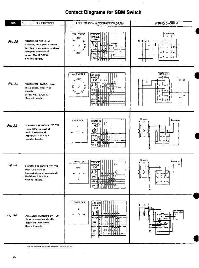
VOLTMETER TRANSFER
SWITCH three-phase transshy
fers four wires phase-to-phase
and phase-to-neutral
Model No I 0AA006
Knurled handle
Fig 30
Fig 31 VOLTMETER SWITCH two
three-phase three-wire
circuits Model No 10AA007
Knurled handle
Fig 32 AMMETER TRANSFER SWITCH
three CTs (connect at
end of secondary I
Model No I 0AA00B
Knurled handle
Fig 33 AMMETER TRANSFER SWITCH
three Cls with off
connect at end of secondary)
Model No 10AA009
Knurled handle
Fig 34 AMMETER TRANSFER SWITCH
three independent circuits
Model No I 0AA01 0
Knurled handle
ESCUTCHEON ampCONTACT DIAGRAM
VOLTMETER CONTACTI HANDLE
OFF
lt ENO u u~las(J 0 3 2 lo
X
8~ ~tooj
XXX OFF 5 X ~~ X~tooj
VOLTMETER CONTACTS HANDLE
ENO _ Ibull u
8~ I uI Ilas N-o I~tooj 3~iltOI 14 5 XX~ool 6 xx
_ NU
I I I U N-o X X
IX X
X X
_ -I I I-N -0
IXX xx X
X
7 IX~ool 8 X
AMMETER lONTACT HANDLE
ENO2
las8i0 XXIpf~ 2 I~ XX
~~ X14
-X X
X X X X
XX XX X X
i6 5 ioi
XX
AMMETER CONTACT HANDLE
OFF ENO
JINsectI~ 0 - -XX XXXr-iteol XX
XX 2
X XXHi6oi XX X X XX XX1-itltgti XX X
AMMETER ~ONTACTI HANDLE
ENO2
I8 asc
u
~ xx X XX
XX
-0 XX XI X XX XX
H~ XX XX~ 14 XX X
XX X5 ~~ X X X X X X XX6 r X XX X XX IX XH~ I XX
WIRING DIAGRAM
-
Source 3 2 I
Source 3 2 I
3 2
9 XXHfltgt ~
x in all contact diagrams denotes contacts closed
I
I
30
I
Contact Diagrams for SBM Switch
- DESCRIPTION
Fig 35 AMMETER TRANSFER SWITCH
two CTs
(connect at end of secondary)
Model No I 0AA0I I
Knurled handle
-AMMETER TRANSFER SWITCH
two CTs with off
(connect al end of secondary
Model No I0AA012
Fig 36
Knurled handle
I Fig 37 AMMETER TRANSFER SWITCH
three independent circuits
with off
Model No 10AA013
Knurled handle
Fig 38 AMMETER-VOLTMETER -TRANSFER SWITCH threeshy
phase three wires phase-toshyphase plus three independent current transformer circuits
Model No I0AA014
Knurled handle
ESCUTCHEON amp CONTACT DIAGRAM
AMMETER toNTAC~ HANDLE
2 END
lz lN bull-8~0 I XX
lliltgt1 ) X X X X ~ X X gti~ 14 XX X X
AMMETER CONTACTS HANDLE
OFF END 018 i5
i N - trltl 0 I XX X XX~tobi ) X X X XX ~ IX
2 XX X XgtI~ 4 X X X XX
AMMETER tONTAC~ HANDLE
ENDOFF lOli5 lN8 irltl O - ill -
X X X XX XXXX X X ~fool2 X X X X X XgtiiSol X X X
X XXlgtitltSoi XX X X X X X X X X X X X X XX XX X X X XtilltRgti XX X XX XOjfo H-___
AMMETER ~ONTACTSVOLTMETER HANDLE
OFF END
lO~1i58 irltl 0 lI2I IY
l3 lIY IY IY
xxxx xxlltltloito i2 X xx XXX2 oitloi11~ XXX
ltgtitoolI 5 X xx 6 X xx XX X XX X 7
xx X X XIX XIX XIX XXXlltloito A X xx
QI xxoi1o II Xli fool~ IX12
XIX xxx11oi1oltgt1~ Iti XIX XXX
WIRING DIAGRAM
Source 3 2
Source 3 2
3 2
3 2 I
x in all contact diagrams denotes contacts closed
31
Contact Diagrams for SBM Switch
DESCRIPTION___________________ESClJTCHEON amp CONTACT DIAGRAM WIRING DIAGRAM
-
Fig 39 AMMETER-VOLTMETER
TRANSFER SWITCH threeshy
phase four wires phase-toshy
neulral plus three independshy
ent current transformer circuits
ModeNo I0AA015
Knurled handle
Fig 40 AMMETER-VOLTMETER
TRANSFER SWITCH
three-phase three wires
phase-to-phase plus
three current transformers
connect al end of secondary)
Model No 10AA016
Knurled handle
Fig 41 AMMETER-VOLTMETER
TRANSFER SWITCH
three-phase four wires
phase-to-neutral plus
three current transformers
(connect at end of secondary)
Model No 10AA0 I 7
Knurled handle
AMMETER VOLTMETER
OFF
0
2
AMMETER VOLTMETER
OFF
0
2
AMMETER VOLTMETER
OFF
0
2
ONTACTS HANDLE
ENO
8~i5 litooito
61~l
ltgtI~~
9lt6ofto
bilo~to I
oi~lol IX I2 IX
~ONTACTI HANDLE
ENO
i58~ 3 2 I I XI~ X xx~t6o
~t6o II
lrH1 1Mt6ofbull1 I
ONTACTI HANDLE
ENO
Ji58~ ~~
~~
4~
ltgtitfiio
oiigt r
u u
lO ~ 0I XIX
2 xx IX IX ~ IX XX) XX~
IX XX XXX X
X xx IX X
xx xx XXX XXX
xx xxxx xx XIX XIX
IX
u u
o xx
2 XXX1x1x1x13 X XIX~t6o XXX14
5 X xx xx xx X xx
IX IX
X XX
X X
u u
l(O2 llf I3x
IX IX X
XXX XIX) X xx
IX X xx xx xx XXX
X X
X I
N321
32 I
N 3 2 I
Ammeter
2
4
6
8
Voltmeter
Ammeter
Voltmeter ti Ammeter
2
4
6
8
Voltmeter
--------+----------If---------u
middot= i -+ D ~u -+-BREAKER CONTROL
Fig 42 CIRCUIT-BREAKER CONTROL
SWITCH
Model No 1OAA100
Pistol-grip handle --+----++--~---- +Fuse ---4----++--------~~------ or
y
---+-~T-ri--p-p-ng~b-us- +Operating bus+c ------- y
-----------------------------------------------ti ~ in all contact diagrams denotes contacts closed
32
X
Contact Diagrams for SBM Switch
NO ~ DESCRIPTl0N ESCUTCHEON amp CONTACli DIAGRAM
c u - ~ ~
c ~ -~BREAKER CONTROL ~I~ ~6 ~ 0CONTACTS aa -+ 0 ~u -+- a 0 0 u - HANDLE t
01~ END -laquo ~
i I 0
0 8 c ~ ~~Fig 43 CIRCUIT-BREAKER CONTROL X
SWITCH ltgtI tor to X X XModel No 10AA101 ~~to Bell
Pistol-grip handle X
XX -t+++-t------++-+ X o~ +-++-=cc_cc_-+ - or y
~~-IIltgt 7 XX -++--+=--~----+-+8 xx
Spring return
BREAKER CONTROL ONTACTS HANDLE
J ltlENDFig 44 TRIP SWITCH a_a
contacts normally open ao01~8 c gt-Z Model No 1OAA102
f-ltuj I X 2 XPistol-grip handle
Spring return
I BREAKER CONTROL ~ONTACTS
HANDLE END
J
Fig 45 TRIP SWITCH =acontacts normally closed 01~ ao8 c gt-Z
Model No 1OAA103 X~ I 2 XPistol-grip handle
Spring return
BREAKER CONTROL
1+ Trip coillFig 46 Cl RCU IT-BREAKER CONTROL
SWITCH for operating Trip coil4two breakers
Model No 1OAA104 Closing coil 5 Closing coil6
J ti2
Pistol-grip handle
Con tac tor BREAKER CONTROL coil~ONTACTS
HANDLE ENO wlaquo
J
Fig 47 SWITCH SUBSTITUTE sectff-~~~ ~oafor push-button station c vZgt-
~~i I X X Model No I 0AA 105 2 X X
Pistol-grip handle 3 X~i
Spring return
x in oll contact diagrams denotes contacts closed
33
Contact Diagrams for SBM Switch
DESCRIPTION ESCUTCHEON amp CONTACT DIAGRAM~--------------------
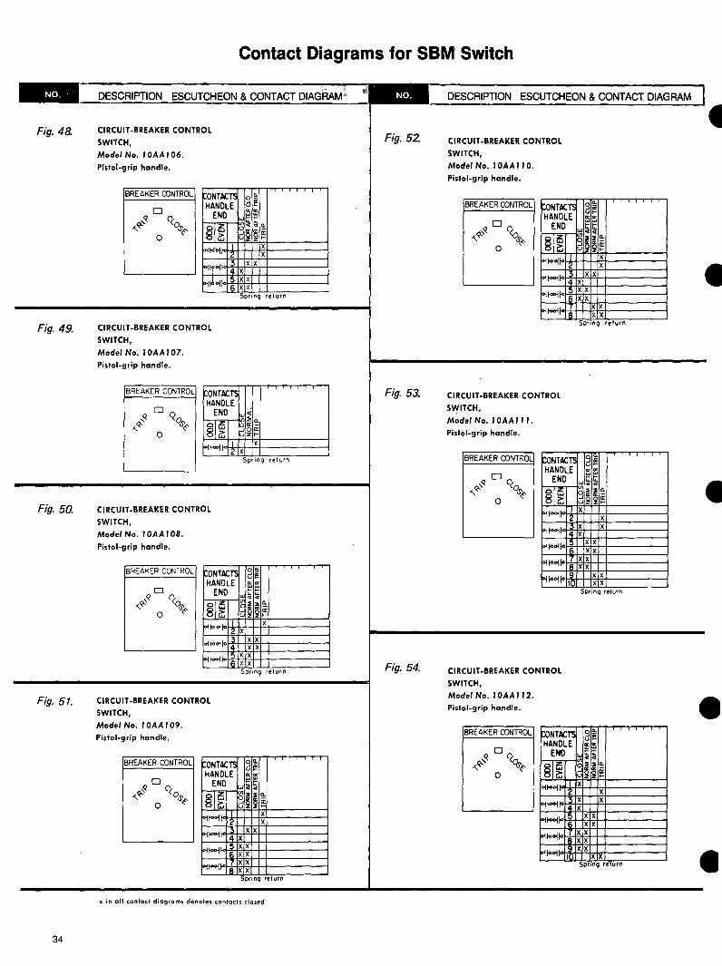
Fig 48 CIRCUIT-BREAKER CONTROL SWITCH Model No I 0AA I 06
Pistol-grip handle
BREAKER CONTROL CONTACTS O
HANDLE g~ ENO ~ ~
~I~ ~~Cl
811 dsectsect~
Spring return
Fig 49 CIRCUIT-BREAKER CONTROL
SWITCH Model No I0AAl07
Pistol-grip handle
BREAKER CONTROL ONTACTS HANDLE J
-E~N=-0-Vli Cl
sl~ g~ Spring return
Fig 50 CIRCUIT-BREAKER CONTROL SWITCH Model No I0AAI0B
Pistol-grip handle
BREAKER CON IROL ONTACTS ~ i HANDLE ~ ~
ENO ~ ~
sl~ J ~lltgtoiio I X
2 X
Spring return
Fig 51 CIRCUIT-BREAKER CONTROL SWITCH Model No I0AA109
Pistol-grip handle
BREAKER CONTROL CONTACTS ~ ~ HANDLE
ENO $S 01~ ~2ECl
811 ~Hr~
DESCRIPTION ESCUTCHEON amp CONTACT DIAGRAM I t
Fig 52 CIRCUIT-BREAKER CONTROL
SWITCH Model No 10AA 110
Pistol-grip handle
BREAKER CONTROL
~~1ltgtmiddotmicrobull4-x~x~xe+--1-----~ I Spring return
Fig 53 CIRCUIT-BREAKER CONTROL SWITCH
Model No I0AA 111
Pistol-grip handle
BREAKER CONTROL
lt DC
lto ~ ~lt
0 I filitltgtHc+xc+--+-x+------i
~1ltgt~ltgtif--+x+x+-1-----~XX
Sprinq return
Fig 54 CIRCUIT-BREAKER CONTROL SWITCH Model No 10AA 112
Pistol-grip handle
BREAKER CONTROL
XX~1ltgt~1ltgtmiddot~1stt+x+-xt-----~ Sprinq return
Spring return
x in all contact diagrams denotes contacts closed
I
34
Contact Diagrams for SBM Switch
DESCRIPTION ESCUTCHEON amp CONTACT DIAGBAIVI DESClUPTION ESCUTCHEON amp CONTACT DIAGRAM-------~~~ -
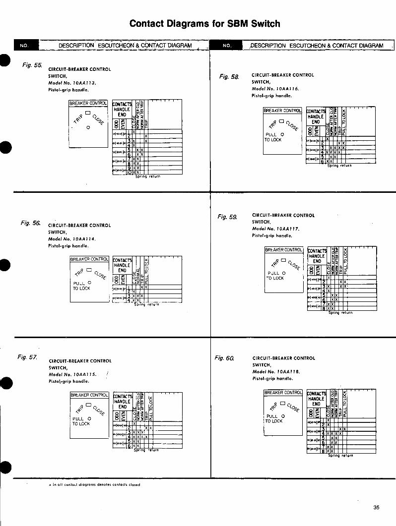
Fig 55 CIRCUIT-BREAKER CONTROL - CIRCUIT-BREAKER CONTROLSWITCH Fig 58 Model No 1OAA11 3 SWITCH
Pistol-grip handle Mode No 1 OAA 116
Pistol-grip handle
BREAKER O)NTROL 9 ~NTACTS ulHANDLE BREAKER CONTROL IdCONTACTSD ENDq (lto ~n HANDLE 8 J
__~ S~ O END 12~~I Cltoli5 ~s~8 i z Q J0 -lt s~ ~s l X p~sectI~ltgtltoltgti PULL 0X
XTO LOCKX ltgtltoltgtijoX XXltgtI toltgtI Iltgt X XX XXX X ltgtltoltgtljo xx XXltgtltoltgtifo XX XXxx ltgtI toltgtI fo xx- Ptoltgtifo xx Spring returnxx
P1ltgtltgt11ltgt1 JXX SpnnQ return
CIRCUIT-BREAKER CONTROLFig 59 SWITCHFig 56 CIRCUIT-BREAKER CONTROL Model No 1 OAA 1 1 7
SWITCH Pistol-grip handle
Mode No 1OAA114
Pistol-grip hondle BREAKER O)NTR0L CtoNTACTS ul u
HANDLE 15 lli 0 J
BREAKER CONTROL ~ONTACTS u END $5 12 D ltHANDLE g -lt qs-e ~s rJ - J0END gwlaquo sectI~ 3 QPULL 0u
oo1~j XTO LOCKQ 0 ltgtlfltgtoi-I i5 XX8 i QuzPULL 0 XXXXITO LOCK ltgtI toltgtljo X
ltgtltoltgtI jo X 3 2 X
XX ~toltgtI
X XX ltgtI toltgtI fo XX4 XX Spring return ltgtltoltgtijo XX
XX pring return
Fig 57 Fig 60 CIRCUIT-BREAKER CONTROLCIRCUIT-BREAKER CONTROL
SWITCHSWITCH
Mode No I OAA 11 8Model No 1OAA 11 5
Pistol-grip handlePistol-grip handle
BREAKER CONTROLBREAKER CONTROL 9~toNTACTS Ugt-- uHANDLE 9~~ ENO I O ltocs D (lto w~a g -lt s-e__~ s~ ll Q Ja1d - PULL 0PULL 0 sl~ ~efi
J
TO LOCKXTO LOCK o-toltgti XX XX XX lltgtiiootX XX XX X X
ltgtlfooljo X X XX
XX ltgtlloltgtifo XXlo-ioltgti XX XXlgttoolspring return XX
prinQ return
x in all contact diagrams denotes contacts closed
35
------
Contact Diagrams for SBM Switch
DESCRIPTION ESCUTCHEON amp CONTACT DIAGRAM DESCRIPTION ESCUTCHEON amp CONTACT DIAGRAM
-
Fig 61 CIRCUIT-BREAKER CONTROL Fig 64 CIRCUIT-BREAKER CONTROL SWITCH SWITCH Model No 1 OAA 119 Model No 10AA122
Pistol-grip handle Pistol-grip handle
ooBREAKER CONTROL BREAKER CONTROLCONTACTS ud~ CONTACTS a~ gHANDLE 5 ~HANDLE ~~tt0 fENO 0 ENO~DC _lt- clos1 sect2 ~ (os 2 Q _J2i~g lt ~ 0
8~ - _J_J 01i5 _J i 0 asectI~ ~ Q PULL 0 z QzPULL 0
XmiddotTO LOCK XTO LOCKltgttooito 1togtitoXX XX XX X X XX X X11ltgt1to ltgtlltgtotoXX XX
X X X X ioitooi ltgttooiloX XX XX XXltgttooito XX 0 0degoifo I xx SpnnQ return prin return
CIRCUIT-BREAKER CONTROLFig 65 SWITCHCIRCUIT-BREAKER CONTROLFig 62
SWITCH Model No 1 OAA 123
Model No 1 OAA 120 Pistol-grip handle
Pistol-grip handle
BREAKER CONTROL CONTACTS ~~ g oeBREAKER CONTROL j0 u HANDLECONTACTS _Jw~v~ ~~ 9HANDLE ENO IWW
5 deg 0 ()IENO 2 Q _J~ D $ Co 0 -~
2 Q _J~ 0I i5c Q0 - _J 8~PULL 0 1dsect0 a_Jli5 u
Xz Q8~ TO LOCKPULL 0 oitooi X XXTO LOCK lltgtilltgtoilltgt X X X XX X otoltgtIltgt X XXXX Xfoltoltgtlo X X XX 1toollo XXXX
1-itoollo X X XX oltoollo XXX Xltgttooilltgt I XXXX ltgtltoltgtto I XXSpring return
Spring return
Cl RCU IT-BREAKER CONTROLFig 66CIRCUIT-BREAKER CONTROLFig 63 SWITCHSWITCH Model No 1 OAA 124
Model No 1 OAA 121 Pistol-grip handle
Pistol-grip handle
oe02 BREAKER CONTROLBREAKER CONTROL CONTACTSjo u d~ uCONTACTS v~ 0 g_J HANDLE liHANDLE 0 t tD END IEND t ~ ~ D clt ~~ Qo()_lt Q _J~ I 2Q _J -lt s~ - _J0 IOJlt a -sect 0sectI~li5 Qdsect 2ccI- 5 PULL 0Q8~PULL 0
XTO LOCKI XTO LOCK ltgttooi1to-gtito X2
1 X
X XX X rgtitooi11oltgtilltgt XX X X XX
XX XX X5 X otlooiloltgtltoltgtito XXX X 6
XXXX7 loioololtgtfool XX8 XX XXSpring return follooito I xx 5pr1n re urn
x in all contact diagrams denotes contacts closed
36
Contact Diagrams for SBM Switch
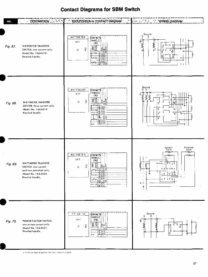
I Fig 67 WATTMETER TRANSFER
SWITCH two current coils
Model No 10AA018
Knurled handle
WATTMETER TRANSFERFig 68 SWITCH three current coils
Model No 10AA019 Knurled handle
I
WATTMETER TRANSFERFig 69 SWITCH two current
and two potential coils
Model No 1 0AA020
Knurled handle
Fig 70 POWER-FACTOR SWITCH
one or two current coils
Model No 10AA021 Knurled handle
WATTMETER ONTACTS HANDLE
OFF END
1-0 i0 z I
I Joi lo 2 ~
biiltgto 4 5ltgtI~ 6
WATTMETER ONTACTS HANDLEOFF ENO
0 rnrn-i0 z IliOltgtli Z ~
IIltgt 4 5
ol ifdeg 6 7~inllltgt R q
Iiiltgt
WATT METER
OFF
0 0 z
PF SWITCH ONTACTS HANDLE
OFF END
01~0 8 i0 z Il~Iltgt Z
LL Z LLoo
XX X X XX XX XX
XX
LL
~~ xx
X X XX XX XX
XX XX
X X XX
LL
5~ xx
X X
Source 3 2
Source 3 2 I
Current Potential Coils Coils
Source 3 2
~ XX ltgtltIltgt
x in all contact diagrams denotes contacts closed
37
---
Contact Diagrams for SBM Switch
_____D_Es_c_R_1PT_1o_N__$ -1---E_sc_u_r_c_HE_o_N_amp_co_NT_A_cr_o_1_AG __ _____w_1_R1_NG_o_1A_G_RA_M______I__RA_M
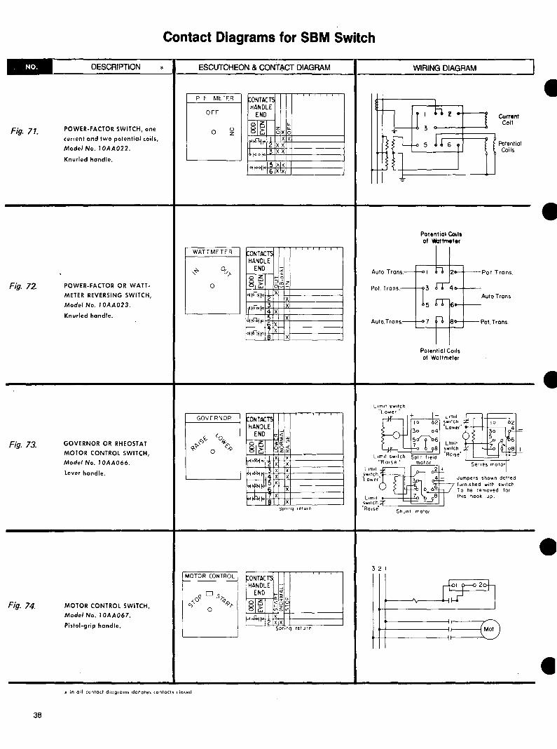
POWER-FACTOR SWITCH oneFig 71 current and two potential coils
ModeNo I0AA022
Knurled handle
Fig 72 POWER-FACTOR OR WATTshy
METER REVERSING SWITCH
Model No I 0AA023
Knurled handle
Fig 73 GOVERNOR OR RHEOSTAT
MOTOR CONTROL SWITCH
Model No I 0AA066
Lever handle
Fig 14 MOTOR CONTROL SWITCH
Model No I 0AA067
Pistol-grip handle
p F METER 0NTACTS HANDLE
OFF END 11 z ~1~0 I~8 G OJ( O0 z
I xx~r 2 XX
XXbqo~to
OifoltgtHbull 5 X X6 XX
WATT METER 0NTACTS HANDLE
END
3 IX-~IOiomicrol44-X+-l-+--------I
GOVERNOP 0NTACTI HANDLE
END kt ~---1~1 1
q~ ~~~ 8ic JZCl
deg 1 X
I X
Spring return
MOTOR CONTROL
I I n l w Current~n--Li 3
I
Coll
~~t---6 Potential Coils
n_i-0 5 l s y n I
0
I
-Potontial Coils of wattmeter
AutoTrans--ltgt n 2--PotTrans
Pol Trans- 3 4--Auto Trans
5 rr-~----_-AutaTrons-f-07 gt6 IAltgt--+--PotTrans
Potential Coils of Wattmeter
I lomot r=
switch r I IO 02 Lower
3o ~-= Umlt ~-Qi ( ~G
switch -~ ~ ~ + Rose ~ -L1m1t switch Split field 1
lomt ~Roise2 + Seoes motorImotor
SWtlCh Lower 4 - Jumpers shown dotted3
furnished with switch6 To be removed for
Limt 7 8 ths hook- up switch Ro1sf
Shunt motor
-3 2 I
x in all contact diagrams denotes contacts closed
I
38
Contact Diagrams for SBM Switch
__bull____DE_s_c_R_tP_T_IO_N__-1--Es_c_u_T_C_HE_O_N_+amp_C_O_NT_A_c_T_D_IA_G_RA_M__-tmiddot------w_t_R_tN_G_D_IA_G_RA_M____~
I
I
SYNCHRONIZING SWITCH
machine-to-bus
with interlocks
Model No 1 OAA 024
Fig 75
Uses removable oval handle
23WW145 bull
Fig 16 SYNCHRONIZING SWITCH
running and incoming
ModeNo 10AA025
Uses one each removable
oval handle
R = 23WL235 bull
I= 23WR235 bull
Fig 77 SYNCHRONIZING SWITCH
between machines without
potential transformers
Model No 10AA026
Uses removable oval handle
23WW123bull
Fig 78 MOTOR CONTROL SWITCH
for split-field motors
Model No 1OAA065
Pistol-grip handle
x in all contact diagrams denotes contacts closed
bull Removable handles must be ordered separately
SYNCHRONIZING CONTACTS HANDLE
ENDOFF 01 u z uI~8 G oo0
I Ioi1ooiro 2 X
31)ot iootro14 1
SYNCHRONIZING
OFF ~ -I
0
SYNCHRONIZING] ONTAC~ HANDLE
END z ltf -
0 1lz I ltDR8~
I X~r X ltgtltni ~ X
Ill~ 4
MOTOR CONTROL CONTACTS HANDLE
-END Clltfw
~~~ 15~~sl~
I Xloi~ 2 X Spring return
2-+-+---+-----------31-+~--+-+----------
----------------2-+--------------++--3-+-h-------------++--
1-----------------+-2-+--------------+--3 -+-h----------------1+
Limit switch 11 +Lower
0
Limit switch 11
Raise11
split ferd motor
39
I
Contact Diagrams for SBM Switch
DESCRIPTION ESCUTCHEON amp CONTACT DIAGRAM DESCRIPTION ESCUTCHEON amp CONTACT DIAGRAM
SINGLE- OR DOUBLE-POLE
Fig 79 single-throw maintain contact
Model No 10AA027
With spring return
Model No 10AA028
Oval handle
OFF Q 11
0
THREE- OR FOUR-POLE Fig 80 single-throw maintain contact
Model No 1 0AA029
With spring return_
Model No 10AA030
Oval handle
CONTACTS HANDLE
END OFF Q -
3 -0 1 0sl~ I Xoft- Z X 3 X
ioftoI 14 X
FIVE- OR SIX-POLEFig 81 single-throw maintain contact
Model No 10AA031
With spring return
Model No 10AA032
Oval handle
OFF Qz_
0
B SEVEN- OR EIGHTshyPOLE single-throw maintained Model No 10AA033 With spring return Model No 10AA034
CONTACT5 HANDLE
END
01i58~ bullHbullltgtito
ltgtilltgtol
ltgtiloolio
zt 0
X X X
X X X
C NINE-OATEN-POLE D ELEVEN- OR single-throw maintained TWELVE-POLE singleshyModel No 10AA035 throw maintained With spring return Model No 10AA0037 Model No 10AA036 With spring return
Model No 10AA038
SINGLE-POLE doubleshy
Fig 82 throw with off maintain contact
Model No 1 0AA039
With spring return
Model No 10AA040
Oval handle
~NTACTS HANDLE
END OFF 2 -
-NO-
I
sl~0 X
oft6lgtifo 12 X
DOUBLE-POLE double-throw Fig 83 with off maintain contact
Model No 10AA041
With spring return
Model No 10AA042
Oval handle
OFFlt
0
THREE-POLE double-throw Fig 84 with off maintain contact
Model No 10AA068
With spring return
Model No 10AA043
Oval handle
OFF 2
0
B FOUR-POLE doubleshythrow with off maintained Model No 10AA044 With spring return Model No 10AA045
~TACTS HANDLE
END -I
NO-sl~ I Xolpoundj 2 X I XPtooi
~TACTS HANDLE
END
sl~ ltgtil6bifo
il6gtito
ltgtil6bllo ~
I
14 X
-I
NO-
X
X
X
X
X
X
C FIVE-POLE doubleshythrow with off maintained Model No 10AA046 With spring return Model No 10AA047
D SIX-POLE doubleshythrow with off maintained Model No 10AA048 With spring return Model No 10AA049
x in oil contact diagrams denotes confects closed
I
I
40
--
Contact 1Diagrams for SBM Switch
Fig 85 SINGLE-POLE double-throw
Model No 1OAAOSO
Oval handle
~NTACTS HANDLE
ENO
li5 N-8 Gi0 I
ol~ ~
Fig 86 DOUBLE-POLE double-throw
Model No 10AA051
Oval handle
~ONTACTS HANDLE
END lt
0 018 i5
Gi Iltgtl~jo 2 3
ltgtl~lo 14
Fig 87 THREE-POLE double-throw
Model No 1OAA052
Oval handle
ONTACTS HANDLE
ENO
lt I8 i5Gi0 Iloi~i 2 3
Oifbb1 4
fllltfbljo 5 n X
B FOUR-POLE double-throw Model No 1QAA053
C FIVE-POLE double-throw Model No I 0AA054
X X
N-
X X
X X
N-
X X
X X
X
x in all contact diagrams denotes contacts closed
D SIX-POLE double-throw Model No I 0AA055
E SEVEN-POLE double-throw Model No I QAA056
SINGLE-POLE three-throw maintain contact Fig 88 Model No 1QAA057
Oval handle
~ONTACTS HANDLE
ENO 2 J 0115
CN-8 Gi Oil-6gtjjo I
0 X
2 X 3 Xpile
~
SINGLE-POLE four-throwFig 89 Model No 10AAQ58
Oval handle
3
i-ONTACTSHANDLE
ENO
I 8 i51 N- X
loi~i~ X X3
IOi~lo 4 X
Fig 90 SINGLE-POLE five-throw maintain contact Model No 1OAA059
Oval handle
i-ONTACTS HANDLE
ENO 1 3 fl Wf~
-N-- 0 (JI 1 XOi~i
X XOi~lo X
Xltgtiiltgt
41
I
Contact Diagrams for SBM Switch
DESCRIPTION ESCUTCHEON amp CONTACT DIAGRAM DESCRIPTION ESCUTCHEON amp CONTACT DIAG~--------------
SINGLE-POLE six-throwFig 91 Model No 1 0AA060
Oval handle
kONTACTS HANDLE
END
~8 Gj N-
I Xoi~lo 2 X
Xloitolgtito ~ X
5 Xltgt116bito i c X
Fig 92
Fig 93
Fig 94 DOUBLE-POLE four-throw
Model No I 0AA063
Oval handle
3
tONTACTS HANDLE
END-~Gi oltampbj
oijolgtjto-bjjolgtjfoll
loitampgtifol I
1N-17
X X
X X
X X
X X
SINGLE-POLE seven-throw
Model No 1 0AA061
Oval handle
tONTACTS HANDLE
END
N-rnrn -Gi Xoifolgtjlo6 5 i X
Xfol tolgtito X Xloi~to Fig 95 DOUBLE-POLE eight-throw
X X
Model No 1 0AA064ltgtIto
Oval handle
t(JNTACTIHANDLE
END
SINGLE-POLE eight-throw
Model No I0AA062
Oval handle
ONTACTS HANDLE
END
~8 Gj
loitltgtoito
pildoito
loi ldoi to
ol tampgtito
X X
X X
X
X
N-
X X
~ I s
I- 0 (gtI sectI~ deg M-
6 5
I XltgtI fool tomiddotHcH--IH-+-+x4-IH-+---i12
x in all contact diagrams denotes contacts closed
42
I
I
I
I
Contact Diagrams for SB-1 Switches
____o_E_sc_R_I_PT_I_O_N__--1--_E_s_cu_r_c_H_E_O_N_amp_CO_NT_A_C_T_D_IA_G_RAM_--11--------W_I_R_IN_G_D_IA_G_RA_M______
VOLTMETER SWITCH Fig 96 double-pole single-throw
Model No 16581 CA I
Knurled handle
VOLTMETER I ONTACTS HANDLE
OFF
LJ END
loJZ-81~
Ip-Kgtltgt 2
I SourceI I Voltmeter I
5t00 XI 2 XI
VOLTMETER SWITCH - ig 97
double-pole double-throw
Mode No I 6S81CE27
Knurled handle
VOLTMETER SWITCH Fig 98 phase-to-phase or
phase-to-neutral
Model No 16S81 CFI I
Knurled handle
Fig 99 VOLTMETER SWITCH threeshy
phase phase-to-phase
phase-to-neutral
Model No 16S81 CFI 6
Knurled handle
Fig 100 VOLTMETER TRANSFER
SWITCH three-phase
four wires phase-to-neutral
Mode No 16S8 I CF22
Knurlltd handle
x in all contact diagrams denotes contacts closed
VOLTMETER (ONTACTHANDLE
END I N-
I I Ui58 i 32 I N-0
ltgtI X xx middotmiddot-I gtI~1-0-1 4 xx
xx Xfrac121o ~ X
7 X X~
VOLTMETER ONTACTI HANDLE
2 END f -
shy -- 0 i5 32 lo 0
8 i IX~ffit i~ X
J ~ 3 I~ M 14 XXX
VoltmeterSource 2
3 4
Source 4321
I 3-phose 3-wire
Move this Jumper to 1-2 when connecting
Jumper not furnished with switches
switch 3ltgt 4 sw
3-phost 4-wore (future alternate connection)
Source N 3 2 I
2 3
Voltmeter
N 3 2 I
2
43
VOLTMETER
OFF ~
0
VOLTMETER
It 0 0
ONTACT HANDLE
END
lz8~ olt1bull01to I
2
~
ltgt~to
ONTACTS HANDLE
END
2 cj I X
x X I I
IX 1
N-
l
-
-~ -o~1i58 i _I Iv ltgtllooi xx
I X ~~ 14 X
43
_ ___ __ ___
I I
Contact Diagrams for SB-1 Switches
__t_middot_middot__o_E_s_cR_I_PT_I_O_N__middotmiddot~iiJ4if---_E_sc_UT_middot_C_HE_O_N_amp_co_N_middot-A_CT_middot_0_1AG_RA_M_middot__middot-ll---~-1__middot ____middot_middot~w1_11_1N_C3___D 1AG_RA__M______
VOLTMETER Voltmeter
Fig 101 VOLTMETER TRANSFER
SWITCH two three-phase
three-wire circuits
Model No I 6S8 I CF23
Knurled handle
Fig 102 AMMETER TRANSFER SWITCH
three independent circuits
Model No 16SBICA7
Knurled handle
Fig 103 AMMETER TRANSFER SWITCH
three independent circuits
with off
Model No 16SB 1 CA 1 5
Knurled handle
Fig 104 AMMETER TRANSFER SWITCH (connect at end of secondary)
Model No 16S81CA18
Knurled handle
~ ~ OFF
II middot1 i t 1 bull Il I 1
I I i I i
1 I 1 i I ~ i
3))2 I X xx X XIX XbullX
IX X XX
XX X XX xx XXX XXX
X
xx xx xxXX X X XX
LL LL
3~2 I~ flE I xx xx XIX IXIX
xx XX
XX X X ~ XX X X X )
XIX X X X X XXX
~IX
21 I3 lgtltIXX
IX
XXX xx xx
xx
3 2 I 3 2
--t----i--ltgt3
--t---t-----t-lt5
7
For three independent circuits remove jumpers 1C-SC and 5C-9C
For three independent circuits remove jumpers 1C-SC and 5C-9C
Source Ammeter 3 2
AMMETER
2
0
AMMETER
2lt o 0
0
AMMETER
2 J
0
oNTACTS HANDLE
END
olz8~ ~middot17-
(i ldegI
~~middot frac12flt
ri81deg ~~
I IZ I~
5 16
I
~ II I I
~NTACT HANDLE
END
middotw~8~ plli
Ir- I rbull I
ri tJ -
lflodeg
l 3
6
~ I II
ONTACTI HANDLE
END
las8~ lotbulli
iof-01
oitbulli
-
x in all contact diagrams denotes contacts closed
44
I
I
Contact Diagrams for SB-1 Switches
ESCUTCHEON amp CONTACT DIAGRAM WIRING DIAGRAMDECRIPTION frac34if -et~ lj i
Fig 105 AMMETER TRANSFER SWITCH three current transformers
with off
(connect at end of secondary)
Model No 16S81 CA 19
Knurled handle
AMMETER TRANSFER SWITCHFig 106 two current transformers
with off
(connect at end of secondary)
Model No 16S81 CA20
I Fig 107 AMMETER TRANSFER SWITCH
two current transformers
(connect at end of secondary)
Model No 16S8 I CE2 5
Knurled handle
ig 108 AMMETER TRANSFER SWITCH four independent circuits -plus off
Mode Ne 16SBICF17
Knurled handle
AMMETER r-ONTACTS HANDLE
2 END J
ILm-shy I~ 0
23~- 0 I X XIXXXX~f-0 2 XXX 3 XX xx XXOirltgt-1 14 XXX
xx xx xx5Pl~ 6 XX
IAMMETER -ONTACTS IHANDLE I2 END
J I IL~1 i5- 3f I~
0 28~- 0
I X-X xxgtIt-ltgt 2 iX xx xx
xx IX X3 Ibir0 4 XIX xx
AMMETER
2
J
0
Positions HANDLE
CONTACTSAMMETER
OFF END M4M ~- 3Mil 2 ~middot~I) XXX~~y-H-o~ XXX
3XX XXX XX XXXX x~I XXri~~ 4XX XXX XXX XXX xmiddotxx x XXX~~-H-o--l
6 XXX 7 XXX
ltgtitHH-ltgt ex xx 9X XXX XXX xx XiX X XXX ~~~ IC X X XXX xx xix x XXX II XX XbullmiddotHmiddot-ltgt--l 12X xx I
Source Ammeter 3 2
Source Ammeter3 2
Source 3 2 Ammeter
Ammeter
Source 4 3 2 I
x in all contact diagrams denotes contacts closed
45
Contact Diagrams for SB-1 Switches
DESCRIPTION ESCUTCHEON amp CONTACT DIAGRAM WIRING DIAGRAM
Fig 109 AMMETER-VOLTMETER
TRANSFER SWITCH threeshy
phase three wire phase-toshy
phase plus three independent
current-transformer circuits
Model No 16S81 CA21
Knurled handle
Fig 110 AMMETER-VOLTMETER TRANSFER SWITCH threeshy
phase four-wire phase-toshy
neutral plus three independshy
ent current-transformer circuits
Model No 16S8 ICA23
Knurled handle
Fig 111 AMMETER-VOLTMETER TRANSFER SWITCH
three-phase three-wire
phase-to-phase plus
three current transformers
(connect at end of secondary)
Model No 16S81 CA24
Knurled handle
Ammeter 3 2 I
AMMETER toNTACTI VOLTMETER HANDLE
ENDOFF
2 ~t ~0 15
8 i 3~ I IX XIX XIX XIX X X xx0 i H 2 X xx xx xx xx xx I I X XX~ f 14 XXX2 1X XX5~- ih XXX 7 X xx xx X XIX XXX ~~ I
fO II XXX 11 XIX X Ifrac12i
i I IX~~ I I
I XIX XIX X I Ilt X
~iio
oi 118
AMMETER ONTACTI VOLTMETER HANDLE
ENDOFF
0 15 8 i 3
bull I x X xx0
I 4
2 5 cbull h 7rf-ltl
( IC II~-fo
fi~III
~middot lh
AMMETER QNTACTIVOLTMETER HANDLE
END2 J
t 0 0
X xx XXX
XX X
2 xx XX
X xx IXIX
xx xx
~
I I
xx XIX X
X
fffltgt-i I~ X ~ X~ X X X
gtif-0-i 5 X XIX XIXIX xx
N 3 2 I
II iI I I 1 ~11Lf I 1
xbullxbullx IXIX X XXXIXX
bullX XIXI
iX XXI
i I bull x xx1x I I I I I
XI XI
I I I I I
I I I I
XI I I I I I i I i
Voltmeter
3 2 I
x in all contact diagrams denotes contacts closed
46
7
I
Contact Diagrams for SB-1 Switchesr___D_E_S_C_R_IP_T_IO_N_________ES_C_U_T_C_H_EO_N_amp_C_O_NT_AC_T_DI_A_G_RA_M__-II_______W_IR_IN_G_D_IA_G_RA_M__o______
AMMETER N 3 2 Ir-ONTACTSVOLTMETER HANDLEFig 112 AMMETER-VOLTMETER
2TRANSFER SWITCH ) three-phase four-wire
0phase-to-neutral plus
three current transformers
(connect at end of secondary)
Mode No l6SBICA25 Knurled handle
END 01~
1 I~28~ 3 xx xx IX Xril-o-i XX X
X XXX2X~1-ltgt-i~ X xx IY IYo l(ll(~rltgt
IX X Xlgt1 7 r s IX
IXpitlt
Voltmeter
AMMETER
AMMETER
0FF I6
six current transformers with
Fig 113 AMMETER TRANSFER SWITCH 5 o 2
4 3off (Connect at end of
secondary)
Model No J6SBJCA28 Knurled handle
AMMETER
0FF I6Fig 114 I O 2AMMETER TRANSFER SWITCH - 4 3six independent circuits plus
off Model No 16S81CA29 Knurled handle
x in all contact diagrams denotes contacts closed
I
47
I
Contact Diagrams for SB-1 Switches
0
____D_E_s_c_R_1P_r_1o_N__-11-----E-sc_ur_CH_Eo_N_amp_c_o_NT_A_c_r_o_1A_G_RA_M_--1-------w-1A_1N_G_D_1_AG_RA_M______I
-
Fig 115 CIRCUIT-BREAKER CONTROL
SWITCH
Model No I 6S81 81
Pistol-grip handle
Fig 116 CIRCUIT-BREAKER CONTROL
SWITCH Model No I 6S8182
Pistol-grip handle
----------ti---------+----------
Fig 117 CIRCUIT-BREAKER TRIP
SWITCH contacts normally open
Model No 16S81 83
Pistol-grip handle
-Fig 118 CIRCUIT-BREAKER TRIP
SWITCH contacts normally closed
Model No I 658184
Pistol-grip handle
BREAKER CONTROL CONTACT~ Positions HANDLE
END TripClose Normol~ Cl
0 01lt Xoil-ltgt rbull~ X
X Xi~~i X Spring return
BREAKER CONTROL CONTACT~ Posrons HANDLEi---~N_o_m~o~N~~-m~o--
END Close g1~ o~ir rrip I z I X~ r2~ middotmiddotmiddot- ----gt-x
~~~~3-~X-+--t--t~X~ ~4 X
Sprong return
BREAKER CONTROL CONTACTS HANDLE
ENO
0 I X 2 X
SPRING RETURN
BREAKER CONTROL ONTACTS HANDLE -
ENO t--0-ili5=r-H
0 811 gt-zltgtiHlohH--tx_______ 1 2 X
Spring return
-+- 0
I I Lamps R
I middot ResLamps G
Res
ol o 2 3 4 i )l)IJ Fuse
-HH-f----- + XIll Fuse Closina bus _ or y
~----+ X --Hgt-----+middotOperating bus or y Tripp---+-~~---
x in all contact diagrams denotes contacts closed
48
I
I Contact Diagrams for SB-1 Switches
DESCRIPTION ESCUTCHEON amp CONTACT DIAGRAM WIRING DIAGRAM
I Fig 119 CIRCUIT-BREAKER CONTROL
SWITCH
for operating two breakers
Model No 16S8 I 86
Pistol-grip handle
Fig 120 CIRCUIT-BREAKER CONTROL
SWITCH substitute
for push-button station
Model No I 658 I 87
Pistol-grip handle
I Fig 121 CIRCUIT-BREAKER CONTROL
SWITCH
Model No I 6S8 I 89 Pistol-grip handle
-
Fig 122 CIRCUIT-BREAKER CONTROL
SWITCH
Model No 1658 I 8 I 0 Pistol-grip handle
-
BREAKER CONTROL CONTACT~ Positions HANDLE
END CJ
TripNormolClose
I Cgt X0$$ X
igtifltgtrlfltgt ~ X XXI X
ltgtif-J-H~ 6 5 X
X
I 4
Spring return
BREAKER CONTROL CONTACTlt Positions HANDLE=~ END Close Normal Trip__-$1 1s_
XXiH~IImiddot12 X X gtiRgt 13 X
I Spring return
BREAKER CONTROL CONTACT~ Positions HANDLECJ Norrnol Norrnol
___q ( ofterClose ofterEND TripI lt1p 10
0$$ X~Hfo I
2 X X X~1ltgtiAgti X
X X~~ bull 5ltgtif-06 X X Spring return
wBREAKER CONTROL CONTACTS 0 uHANDLE
DC w 0 END
0~ ~
__I $lt clij 8$8 C ii0 Xltgtil-11lt X
xxltgti~~o X xxltgti~ltgtlilt xx
XXOOoilt I xx ~oring return
x in ell contact diagrams denotes contacts closed
1+ Trip coil Trip1middot ( coil
Closing Closing5 6
coil coil
f ContoctorI I 0 2 coil
13 y
rc-f + -
OT Closing
gt relay
b1 2 ) W lamp+ 3 b 40b _i---o-~- ~ 5 y60-
Bell alarm I b or recloser
+ -
49
Contact Diagrams for SB-1 Switches
ig 126
SCRIPTI middot
Fig 123 CIRCUIT-BREAKER CONTROL
SWITCH
Model No I 6SBI Bl I
Pistol-grip handle
BREAKER CONTROL
D
0
Fig 124 CIRCUIT-BREAKER CONTROL SWITCH
Model No 16SB 1814
Pistol-grip handle
BREAKER CONTROL
D
0
Fig 125 CIRCUIT-BREAKER CONTROL SWITCH
Model No 16581815
Pistol-grip handle
BREAKER CONTROL
bull C 0
s 0
middotTi I
Sprini return
IONTACTS I
HANDLE END
lz8~ I
oiitole
o1ltgt0-to 1
5OilltgtOii 16
ONTACTS HANDLE
END
lz8~ ltgtlttltgtolto ~
gtlo-JoOilo14
5riiooi 6 loltJoojio
18
I
j~ a0 Iu XI
X I XX I XX i
XX l XX I
pr1nq return
I 1 I dl
Jtl ~~middot~j~Ul~I~
x I IX XIXI
X X X i X X I XX I I Xx I I
Spring_ return
DESGRIPTION ESGUTGHEON amp CONTACTi DIAGRAM
CIRCUIT-BREAKER CONTROL
SWITCH
Model No 16S81 8 I 6
Pistol-grip handle
BREAKER CONTROL
0
ONTACTI HANDLE lhlt
END II ~ oo ~ El Ebullbull ~i]2 IC8~ i ~
II Xltgtiltgtltgtlto XI
3 X 2
XltlltgtOi 14 X xx
lltloltgtliol 5 XX Xxlo1ooito XX
l X XoltlltgtOiio xxI
Spr1nQ return
ig 127 CIRCUIT-BREAKER CONTROL
SWITCH
Model No 16S81 B 17
Pistol-grip handle
BREAKER CONTROL
D C
OS
0
C
HANDLE ONTACTS
~Ii END ff
vlo o~z b sect ~ ~ u o o 1-8~ zz IXoltJOltgtIlt I
XI X X
c o-Joolo ~ 1 X
XXoltiooltlo15 XX
XXioioolo XX
Xx ~I -
XX SprinQ reLiLJl
Fig 128 CIRCUIT-BREAKER CONTROL SWITCH
Model No 16S81818
Pistol-grip handle
BREAKER CONTROL
D
0
ONTACTS ~I~ HANDLE I~~ENO
afOO b ~i ~ -wrnrn~ Uj~~~ IX
~
ltgtlttooto ~ X x 1yen I
fgtlltgtot-1~
X XX XmiddotX
IX X
~1lto1r 5
1ltgtltgt11ltgt XmiddotXmiddot XX I
oltiooliltgt I IXIXI Soring return
x in all contact diagrams denotes contacts closed
I
50
------
I
--Contact Diagrams for SB-1 Switches
Fig 132
Fig 129 CIRCUIT-BREAKER CONTROL
SWITCH
Model No 16S8 I B19
Pistol-grip handle
BREAKER CONTROL
D Q c - Osgt
Pull O to Lock
Fig 130 CIRCUIT-BREAKER CONTROL
SWITCH
Model No 16S8 I B20
Pistol-grip handle
BREAKER CONTROL
D
Pull 0 o Lock
Fig 131 CIRCUIT-BREAKER CONTROL
SWITCH
Model No I 6S8 I B21
Pistol-grip handle
BREAKER CONTROL
D
-Q
Pull 0 to Leck
tONTACTS HANDLE
END ~-middot
Sprng return
i i[
r Iltgtiiltgtltgtli 2
3ltgtilltgtolto
ltgtiiltgtollltgt ~ 7
ltgtI iltgto i R
8 ~ = f- a
X XX
X XX
X xx xx
XX XX
Soring rPturn
CIRCUIT-BREAKER CONTROL
Model No 16SB I B22
Pistol-grip handle
BREAKER CONTROL
bull _Q
Pull O to lock
CIRCUIT-BREAKER CONTROLFig 133
Fig 134 SWITCH
Model No I 6S8 I B24
Pistol-grip handle
BREAKER CONTROL
D -Q
Pull O to Lock
SWITCH
ModeNo 16SB1B23
Pistol-grip handle
BREAKER CONTROL
D
-Q
Pull O to Lock
HANDLE END
oJz8~
lo o-qoofO
okgtltgtfo
iooi
o[Z8~
laquotoojr
ltgtI lo ltgtIto
ltgti tooj fo
iltgtltgtllo
CIRCUIT-BREAKER CONTROL
T oJ IONTACTS
I
2 3 ~
~fl I _ I u 1 1-9
~ 010 iP ~ EE~0 +1- = - 0 O _ I U ZZI_ Q
X X i
xx x xmiddotxmiddotx 1
XX I xx I
7XX I R Xxmiddot I
Spring return
1~ONTACTI HANDLE
END It ~ i
ltONTACTS ~19i01 ~ ~[
- - u HANDLE
END ~f ~IoJz ~1~t9-- o-o ~Iuzz_CL
I 8~
Xltgti loltgtl i T X Xr
I XIX XXltgtliltgtltgtito 4 xx
XX1iltgtltgtlfo ~ iX X
xTx Iltgtitoolto R XIXI Spring return
E gt2bull10E Uj ~~ a
T X 2 XX 3 X XX X
xx XX5 f X 7 XX R XX
Spring return
x in all contact diagrams denotes contacts closed
51
Contact Diagrams for SB-1 Switches
DESCRIPTION ESCUTCHEON ampCONT~CT DIAGRAM WIRING DIAGRAM bull
I
bull
BREAKER CONTROL rONTACT5 ~
0 ti JHANDLE u uD EEND-(() Co
SIgt E ile Elz
0 ~ ~Pull zgt- tl8~ ~~ to Lock O
Xolooito ~CIRCUIT-BREAKER CONTROLFig 135 X XI
SWITCH 3 X X XIXlolltgtltgtito 4 XX
Model No l 6SB I B25 5 lllllol loltgtic xxPistol-grip-handle xx Iltgtiloofc Ixx
xx ltgtiloltgti le I XX I Soring return
BREAKER CONTROL ONTACT5 HANDLE 1~1~ uD
END C ~i~Ir i
-g
Osltgt I~ El Ei~ ~I i5Pull O ~1~1~ ~8 ito Lock X
foilooj IX
XXCIRCUIT-BREAKER CONTROL lof ioltgtilltgtFig 136 Ixxxx SWITCH X X1
foiloolo x-xModel No 16SB 1B26 xxltoltgtilo XXPistol-grip handle xx
ltgtI loo I xx xx
loiloltgtiio 2XX pnng return
WATTMETER ONTACT5
Fig 137 WATTMETER TRANSFER
SWITCH three current coils
OFF
0
01
HANDLE END
oli58 i --
~~ Model No 16SBICB13
Fixed knurled handle 71--0--j
Olltgtltgti
XX 2 XX 3 XX 4 XX
Model No 16SBICF8
Uses removable oval handle 16581CC6bull
gt-1ft1 11~
Oil-
5 XX 6 X X 7 xx 8 XX 9 xix
WATTMETER roNTACTI Fig 138 WATTMETER TRANSFER HANDLE
OFF ENDSWITCH two current coils Oz --Model No 16SBIC812 olz z8~ oo--0Fixed knurled handle xx~-ltgt-iiltgt X X
Model No 16S81CF7 3XX ~ o-~ 4 XXUses removable oval handle 5 XXolfltgt-116S81 CC6bull 6 xx
Source 3 2 I
J 1 Igt J J
I 2Igt bull gt Lf3J 6 4 09 9- __
~ 05 gt-- 0y 8 ~
__ ~r -)
Source 3 2 I
I~ I LI Igt I 1 2bulll Dgt--
5Y
~ 6
rY7 1 c____J
t x in all contact diagrams denotes contacts closed
bullRemovable handles must be ordered separately
I
52
Contact Diagrams for SB-1 Switches
DESCRIPTION ESCUTCHEON amp CONTACT DIAGRAM WIRING DIAGRAM
- 4 I-
Potentiol coi Is of Wattmeter
WATTMETER ONTACTS
Fig 739
-WATTMETER
OFF 0z Fig 140 WATTMETER TRANSFER
0 SWITCH two current
and two potential coils
Model No 16S81CB14 Knurled handle
-
POWER-FACTOR OR WA TT-
METER REVERSING SWITCH
Model No 16S81CA10 Two Position
Knurled handle
Model No 16S81CB4 Three Position
Engraved W - off - RVA
Oe_ 0
Fig 141 POWER-FACTOR SWITCH one
current and two potential coils
Model No 16S81CA26 Fixed knurled handle
Model No 16S81CF6 Uses removable oval handle
16SB1CC5 bull
p F METER
OFF O 1-
0
Fig 742 POWER-FACTOR SWITCH
one or two current coils
Model No 16S81CA22 Knurled handle
PF METER
OFF 0z
0
Model No 16S81CA8 Uses removable oval handle
HANDLE _ END 2rm- gt-lt
iizo_ -~ ~M I X
2 X (jfo4 I
4 X X
i~ 5 16 X
X
pjilt-( 7 X 18 X
ONTACTS
I
HANDLE i END Iim- i luuJ
6~~ XXgtHmiddotltgti 2 X Xi
3 XX 14 Xxmiddot 5 XIXbull
~ ~rltgt-1
bullXX 1 x1x1~toltgti IR X XI
I ONTACTI HANDLE
END
m 6~ -
~ xx-ltgt 2 XX
3 XX
- 5 XX -
egtlltXgtj XX
ONTACTI HANDLE
END
1[5 flj XX
8~ gtH-0 1 XX
I XXOj~ 14
Pot IronAuto Irons -I 2
i 0- 4
Pot trans Auto Iron 0- 6
Pot trans Auto trans 7 8
Potential coils of Wottmeter
Current Potential coils cells
le middotvv y
3 2 I
~ I 2
fL _l Ll~ 4y
95 0 6bJ
7 6 8
I I
-
3 2 I
u
J 6 I
2ltrrlCurrent coiln
Potential~~~ coils6sf~ +
Source 3 2 I
J
~ I ~ rti middot I lil 16SB1CC5 bull
x in 011 contact diagrams denotes contacts closed
bull Removable handles must be ordered separately
53
Contact Diagrams for SB-1 Switches
DESCRIPTION ESCUTCHEON amp CONTACT DIAGRAM WIRING DIAGRAM -------bull----------- bull------------
-
SYNCHROSCOPE ONTACTS HANDLEFig 143 SYNCHRONIZING SWITCH OFF END01machine-to-bus aZ
Ziwith interlocks 81~ 000 I X 2
Model No 16SB 1 CF9 -iraquo X
Uses removable oval handle ~ X 4 X
bull ~ol l
16SB1CC7 bull
lSYNCHROSCOPE ONTACTS HANDLEFig 144 SYNCHRONIZING SWITCH ENDIbetween machines without ~- Iii
potential transformers sectI~ r~R0 I XModeNo 16S81C815 ii-o- 2 I X
Uses one each removable ~ XI middot J O-J-
14 I Xoval handles
R = 16SB1CC8 bull
I = 16SB1CC7 bull
SYNCHROSCOPE ONTACTS HANDLE -XFig 145 SYNCHRONIZING SWITCH ENDI z
ltIamiddotzbetween machines J81~ l~R0with interlocks XIgt--gt-iModel No 16SBIC85 2 X _]_ XUses one each removable
oval handles R = 16SB1CC8 bull
I = 16SB1CC7 bull
GOVERNOR ONTACTI HANDLE
J a ltI w wE
ENDFig 146 GOVERNOR OR RHEOSTAT ~ a -MOTOR CONTROL SWITCH alz 00lt1 J z a8~(split-field motors are standshy
XI XgtltH 2 X Xard for most applications)
I-+---+-------
2-+gt--+-------shy3-+f-+--+--1-----
L1m1t switch Low-er
~--+--~ L1m1 2 switch
Lower t-t-+-t----
3 X X~HModel No 16SB1A 1 4 X X
5 XRadial handle T n X I X
XL 8 Spring return
bull in oil conloct diagrams denotes contacts closed
bull Removable handles must be ordered separately
54
I
__ __
Contact Diagrams for SB-1 Switches
___D_e_s_c_RI_PT_I_ON_e_s_cur_c_H_e_o_N_amp_c_o_N_TA_C_T_D_IA G_RA_M DESCRIPTION ESCUTCHEON amp CONTACT DIAGRAM
- Fig 141 MOTOR-CONTROL SWITCH
for split-field motors
Mode No 16SB 1 AA 1
Pistol-grip handle
MOTOR CONTROL
Fig 148 TEMPERATURE-METER TRANSshy
FER SWITCH transfers two
wires to five coils and test
Palladium contacts
ModeNo 16SB1CE33
Knurled handle
TEMP METER
TEST
0 d
3
-ONTACTIHANDLE I
END I I-VJ~-
~
tgtirltgt~
~H~
lgt-1 ~~
lgt-1 ~H
lgt-1 ~1
H~
~ff i N -~ XI
X2 X Xj X
X X X4 X5
X6 X X X7
X X XB Xl
I( X X X XII
XX12 X
Fig 149 TEMPERATURE-METER TRANSshy
FER SWITCH transfers two
wires to three coils and test
Palladium contacts
Model No 1 6SB 1 CE28
Knurled handle
TEMP METER
TEST
rlt) 0
2
ONTACTI HANDLE
END I-
0 VJ15 N8~ -
X tgti~
I X
3 X 2
XX ~ H X X X
5 4
X H lJ1
X 7 6
X X X ~~ X X X 1B
Fig 150 TEMPERATURE-METER TRANSshy
FER SWITCH transfers three
wires to three coils and test
Palladium contacts
Mode No 16S81CE29
Knurled handle
TEMP METER
TEST
rlt) 0 -
2
Fig 151
~ONTACTI HANDLE
ENO
ram-~ 1gt-11ltgt-i
lt j XHi-ltgt
4 5 X1gt-1-ltgt
11
lgt-11ltgt-1
111ltgt-1 X I I
p-lf-o-i X12
TEMPERATURE-METER TRANSshy
FER SWITCH transfers two
wires to four coils
with test and off
Palladium contacts
Model No 16S81CE52 Uses removable oval handle
16SB1CC19 bull
With fixed knurled handle
Model No 16S81 CE61
TEMP METER
OFF _
~A
0
2
ONTACTI HANDLE
END 0 15
8~ p-1~~ I~ X I j
l_I 5
~
lgt-1 XI
HI~ I
12 X XX
X
XX
XX
X
X X
N - X
X XX
X XX
l(N
X
X X
X
X
XX X
XX X
I-
- VJ
X X
I-
VJ
X
X X
X X
-0
X
X X
X XX
X
X XX
x in all contact diagrams denotes contacts closed
bull Removable handles must be ordered separately
55
-------
Contact Diagrams for SB-1 Switches
DESCRIPTION ESCUTCHEON amp CONTACT DIAGRAM DESCRIPTION ESCUTCHEON amp CONTACT DIAGRAM
TEMPERATURE-METER TRANSshyFig 152-FER SWITCH transfers three
wires to three coils
with test and off
Palladium contacts
Model No 16SB1CE55 Uses removable oval handle
16SB1CC19 bull
For fixed knurled handle
ModeNo 16S81CE63
TEMP METER CONTACTI HANDLE
OFF END -lt 0 i5rn
8 c0 Xc 1gt11-ltgt-itoI
X X X lgti-0-l X X X
X X X gti-0-i X X XI
~ X X XgtiJ-o~lktxbx+x+-+-+-+++--+-+-+-+~
Fig 153 TEMPERATURE-METER TRANSshy
FER SWITCH transfers two
wires to three coils
with test and off
Model No 16S81CE57
Uses removable oval handle
TtMPMETER CONTACTS--_0SITI0NS - BACK VIEW IFig 155 6 OF~EST H~~LE 6 5 4 3 2 I ~ ~
5 o I 4 2 1-o-1 ~ 1pound4--+-+--1--1--HHx+--l--i-+-H-+-+~
3
TEMPERATURE METER TRANS- 1-o-1~~t-1--+-+-H-+-+xhx+x1-+-H-+-+-+--I 1
FER SWITCH transfers two ~ 1-o-l i1-~-+--+-+-+-+-h-7t-i1-t--+-+-+-+---t--X-+--t-1 wires to six coils and test 1-~---~+=+-+-+-t-t-txgt+--+-+-+-+--+--+=+JC=+JC-+JC--1
7 8 7Palladium Contacts 1-o-ll-o-ll-o-+1-=+-+-++-+JC+JCgt+Ixgt+-+-+-+--++-+-+-+-l Model No 16S8 I CE67 ~1-o-l ~i~ci---+-+-t-x+-+-+-~-+-+---+IX-gt+-+-+-+-4
1Knurled handle It J2 It X X X
o-l lmiddotltgtmiddotUltgt i-t2=+--+-~11lt-rtx-+x=+x-+-+-+-+--+Jt-Lt-gt+--+--+-- l-~__f-o-l-1plusmn-+-1-X~+u-ir-+-+-+--t-+Art--t-+-t--+-+-t
15 1615 X XIXo-l lmiddotltgtmiddotUbullol1s++x-+xx-+--+-+-+-1--t+-Lgti-gt+--+-+-+- -Fig 156 SINGLE- OR DOUBLE-POLE
single-throw maintain contact
Model No 16581 CG I
With spring return
ModeNo 16581CG2
Oval handle
CONTACTI HANDLE
END OFF O u~115 z
0081c0
16SB1CC19 bull
For fixed knurled handle
Model No 16581 CE62
TEMP METER
OFF -lt rn
0 ~
I
ONTACT5HANDLE
END ~- ~ u
181~ -~-~N-bull-bullmiddot=-~ lgtit~i~+-+2--+-gt--+--+-x+---+-+-+---+----+~
X XX~ to-X X X4
X5gtiio X6
X XX A 7 1-j
X X X
Fig 157 THREE- OR FOUR-POLE
single-throw maintain contact ModeNo 16S81CGJ
With spring return
Model No 16S81 CG4
Oval handle
ONTACT5 HANDLE
END OFF 01 LL
ZLL0 i5 8 c 1000
TEMPMETERFig 154
5 OF~EST 4 or
3 2
TEMPERATURE METER TRANSbull
FER SWITCH transfers three
wires to five coils and test
Palladium Contacts
Model No I6S8 I CE66
Knurled handle
CONTACTS POSITIONS - BACK VIEW
HANDLE Ill
END 1t51tlllll-41111111311112111t1tliw
~fltgt-i ~l-~+-ll-l-+1-++1-++t-++-1-++-lf-+-t-l--t~IP+-Y+i
7 87 JCoH-o-ll-o_+-+-+-1-1-+~+-+-+-+-++-1-+-++-+-ii-+-1-+-+-+-t8
9 10 9 o-jfltgt-lf-o fQ IYIY
13 J4~13fl-+t-+++-+-+-+-t-+-t-H~JC+-+-+-t-++-t--t-+-t-o-t 1-ltgtmiddotlbullo 14 X
15 1615 ltgt-11-ltgtil-ltgt 61JC ll
Fig 158 A FIVEbull OR SIX-POLE B 7-ORBmiddotPOLE C 9middot OR 10middot D 11middot OR 12- -single-throw maintained single-throw POLE POLE 1 throw Model No 16S81CG5 maintained With spring return
maintained single-throw 16SB1CG11
Model No 16S81CG6 16S81CG7 maintained Wspr rel 16S81CG9 Wspr rel
Oval handle 16S81CG12 16SB1CG10
16S81CG8 Wspr ret
~NTACT5 HANDLE
END OFF 01 LL
Z LLsect~ 00 Xotto-ito X X
ottootto X X
oiloltgtllo X
x in all contact diagrams denotes contacts closed
I
I
56
I l
Contact Diagrams for SB-1 Switches
_iOEspR1JgtTPtJ1~spu1bfQNamp comAc101f-GAAM
Fig 159 SINGLE-POLE double-throw
with off maintain contact
Model No J6SBICGJ3
With spring return
Model No 16SB1CG14
Oval handle
lONTACTI HANDLE
ENDOFF lt 1i58~0
Iltgtlt-ltgt-i 12
DOUBLE-POLE double-throwFig 160 with off maintain contact
Model No I 6S81 CG 15
With spring return
Model No 16S81 CG 16
Oval handle
0NTACTI HANDLE
END
OFF
0 lt 01i58~
olrltgti I 2 3
ltgtifltgt-)o 4
-
I Fig 161 A THREE-POLE double-
throw with off maintain
Model No 16SB1CG17
With spring return
Model No 16S81CG18 Oval handle
OFF lt
0
-
B
u u
NO-
X X
u u
NO-
X X
X X
C D 4P-dt wloff SP-dt wfoff 6P-dt wloff maintain maintain maintain
16SB1CG19 16S81CG21 16SB1CG23
Wlspr rel Wlspr rel Wispr ret 16SB1CG20 16SB1CG22 16S81CG24
r-0NTACTI HANDLE
END u0 i5 u
IN o -8~ I X~fo-i 7 X
Xlol ro-ito 13 14 X 5 X
ltgtI rltgtiio 16 X
Fig 162 SINGLE-POLE double-throw Model No 16SB1CG25
Oval handle
t0NTACTI HANDLE
END lt 0 i5
-bull-
X 0 8~
PltH 7 I
X
-
DESCRIPTION ESCUTCHEON ampCONTACT DIAGRAf-1
Fig 163 DOUBLE-POLE double-throw Model No 16SB1CG26
Oval handle
lt
0
A164Fig
Fig 165 SINGLE-POLE triple-throw
THREE-POLE double-throw
Model No 16S81 CG27
Oval handle
lt
0
Model No 165B 1 CG32
Oval handle
2 J
0
Fig 166 SINGLE-POLE four-throw Model No 16B 1 CG33
Oval handle
I
ltt 0 N
3
Fig 167 SINGLE-POLE five-throw Model No 16S81 CG34
Oval handle
31 9
- 0 u
l0NTACTI HANDLE
END
~-~ -
I XoH-o-Hltgt - X I X
ltgti-0-- 14 X
B 4P-dt 16SB1CG28 C SP-dt 16SBICG29
QNTACTS HANDLE
ENO
~-N-~
Xkgtltt-o--to - X Xkgtltrto 4
I X
5 Xltgt1-0--fo f X
-0NTACTS HANDLE
ENO
~-IN-
I ~
XfgtiH X
~xltgtllo
toNTACTS HANDLE
ENO
0 i5 N-8~ XltgtIH X12
I XiolH 14 X
CQNTACTI HANDLE
END
_sect~ W1 X~H X
X~fltgt-lto X Xloio
D 6P-dt 16SB 1 CG30 E 7P-dt 16S81 CGJI
x in all contact diagrams denotes contacts closed
57
------- I
Contact Diagrams for SB-1 Switches
DESCRIPTION ESCUTCHEON amp CONTACT DIAGRAM DESCRIPTION ESCUTCHEON amp CONTACT DIAGRAM
-Fig 168 SINGLE-POLE six-throw
Model No 1658 I CG35
Omiddotal handle
QNTACTS HANDLE
ENO (o ~ C j5
0 8 G c I~H-i z4
ltgtil-ltgt-lfol~ 5ioiH fi
Fig 169 SINGLE-POLE seven-throw
Model No 1658 I CGJ6
Oval handle
4 s I cS
__0
Fig 170 SINGLE-POLE eight-throw
Model No 16S81CG37
Oval handle
~
- (l0 ltls
5
Fig 171 SINGLE-POLE 10-throw
Model No 16S81CG38
Oval handle
)12 0) v
ct) 0 -A
lt C6
X
X
~ONTACTI HANDLE
ENO
N- X
X X
X
li5 N-8 G - XI~1-ltgt-l
2 X
Xbit-ofo1 ~ X X5ioiHto X6
7 Xltgtiiltgt
ONTACTS HANDLE
ENO
la_ N-I8 i5G X
oHfo~ X
ltgtil-ltgt-li1~
ltgtI t-o 5 X i6 X
ltgtHi18 7
X
ONTACTS HANDLE
END C j5
a_ N-Qa ltrl8 G X
ltgt1Hfo~ X 3 Xjojt-o 4 X
Xltgtil-ltgt-lfo 5 X
Xlltgtil-ltgt-lto X
X oil-ltgt-li1 X
x in ell contact diagrams denotes contacts closed
58
SINGLE-POLE 12-throwFig 172 Model No 1658 I CGJ9
Oval handle
l I 2 ~
Q O t
cS c amp 7 ~
ONTACTI HANDLE
ENO 9Ji581i
Iltgtif--gt-l lt 1ltgt1-ltgt-l 14
5
lo t-o
1-it-ltgt-i
fgtll-ltgt-li1 X
fHto II2 X
DOUBLE-POLE lour-throwFig 173 ModeNo 16SBICG40
Oval handle
Sf 0 N
3
ONTACTS HANDLE
END
lz 1 8~ pr-0-j
lt ~pl-ltgt-1
14 5
tgtil-ltgt-1 b X I
tgtil-ltgt-l 18 X
Fig 174 DOUBLE-POLE six-throw
Model No 16581 CG41
Oval handle
~ONTACTS HANDLE
END (o ~~ G 0
Pf-07 I 24 3P-l-ltgt-1 4 5p-1-ltgt-l I X
tgtit-oi X
p1-ltgt-l I X
p 1-ltgt-l I 12 X
X X
X X
X X I
X
X
N-
X
X
X
X
X
X
N-
X
X
Contact Diagrams for SB-1 Switches
____D_Es_c_R_1_Pr_1o_N___-1---Es_c_u_r_c_H_E_o_N_amp_c_o_NT_Ac_r_o_1A_G_RA_M_________w_1R_1N_G_D_1A_G_RA_M______I
-
-
I
-
I
DOUBLE-POLE eight-throwFig 175 Model No 16SB 1CG42
Oval handle
DOUBLE-POLE 12-throwFig 116 Model No 16SB 1CG43
Oval handle
Fig 117 MOTOR CONTROL SWITCH
Model No 16S81 CG44
Pistol-grip handle
~ONTACTS HANDLE
ENO
~-ICX_IOOsfN-
X~-0-i X
X~-0-i X
X ~-0-i X
X~i-o-1 I X
I X11-o-1 12 X X
gtii-o-1 I~ X gt-0-i If X
X
ONTACTI HANDLE
ENOl- I 2 ltY
Q O Jgt
CS V) il -0-i fltHH---1---l-l-+X+--i-++-t-lHX e 7 ~
~ -0-i f-ltH1f+-1-+x+-1-++-i-+x+-+--i-
321
MOTOR CONTROL ONTACTI HANDLE
o- bull s c-lt -1-5gt I i---E-N-D--1d Q_ - ) g~ ~~~ 0
~-0-i IXL 2 XX H---~60Soring return
x in oll contoct diogrom5 denotes contacts closed
59
bull bull
- - - - - - - -
- - - - - -- -
- - - - - - -
-------
- - - - - -- -
- - - - - -
- - - - - -- -
Ordering Guide for SBM Switches
Specification Form GED-3933 has been designed for data-processing equipment and also to make it easier to fill out Refer to Fig 178 and proceed as follows to fill out the form
CD FOR FACTORY USE ONL y (Blocks 9 through 18)
These blocks are for factory use only and should be left blank
CATALOG NUMBER (Blocks 19 through 25)
This number is assigned at the factory and these blocks should be left blank
ACTION
This part of the form is broken into five sections detailed under the five following points (4-8)
MAINTAINED ALL POSITIONS (Block 26)
Put an X in this block if all the positions are maintained and put in a dash (-) if they are not maintained
reg SPRING RETURN FROM COUNTER-CLOCKWISE POSITIONS (Blocks 27 and 28)
Put the number of the position the spring return action is from in Block 27 and the position the spring return is to in Block 28 Put in a dash when this action does not apply
SPRING RETURN FROM CLOCKWISE POSITIONS
(Blocks 29 and 30)
Put the number of the position the spring return action is from in Block 29 and the position the spring return is to in Block 30 Put in a dash when this action does not apply
MAINTAINED POSITION WITH SPRING RETURN (Blocks 31 through 34)
GENERAL fl ELECTRIC
SPECIFICATION FORM TYPE SBM SWITCHES 17 Refer to GEAbull4746 and GETamp169 lor descriptive Information 1)-
YES=X I KNURLED = Ilt I A STANDARDbull S INO- I H OVAL = V 18
C TARGET = T
~ SR FROM Sll FROM MAINlt PULL ~ PISTOL GRIP= P I C y NONE = N I ESCUTCHEONT ALL CclOl I CJI POs TO D LEVER = L
(SPECIAL) = P I KEYWAVS6 POSITIONS POSITIONS I POSITIONS WITH LOCK L ROUND D
N 1 gJtREt ~NONE =N ~ KEYED = R b FOR R[M KOL) I MAI NTAt NED - - SPRING RETURN TO MATCH SB-1- N I
LC==~-~=SB~M=S~WIT~CH~oPE~RA-T-ING-RE-QU~IR~EM-EN~T TABLE 12 USE OILY WHENMARK INTFRtiDIATE POS
1--- -- ~SUP CONTACTS~ (4-~) lARE REQUIREDI r r r r r I
gt-- STANDARD ESC TARGET ESC 5
zPOSITIONSCCNTACTS I2 078 I 4 ~26 4 2 u5 3000 EVENlbull 8l (9 I~
2 I ~ ~~ ~to 2 2
12S-32l 3 3 6
Ol Ill to ~16 4 74 0 D(41-48) 5 5
OI~ _(IO 6 6 )(57-64) 7 8
8 7l POS ESCUTCHEON ENGRAVING 8)
(6-8) OI~ ~to 8 9-~ I I I I I I IllW19- I99 I I I I I I
~to jto 10 middot16)
10 17~4~ Li I I I I middot1 t--2
10 ~ 07 (ZS-JlJ 11 II I I I I I I I33-ltC
41-lt8 I I I I I I~to 0~12 12W-41 I -3 (41-48) I I I I I I I13 13 I I I I I I I
14Oillt deg ~
14 4 -I I I I I I I
1615 (6-8) 165-72(57-64) 15 9--16 I I I I I I III ill
5 -1-- ---1-1-oir iO 16 16 $ 8)
9 16) 17 lgt-32 I I I I I I I17 17 18 ~ 6OI IO OI IO 18 18 I I I I I I I(17-24) ~-141-41 I I I I I I I125-32) 192019 -79
I I I I I I I149-sbullOlllt Jlltlgc 120 ~7 I I I I I
I 18171615141312111 61514 I I 3 I 2 I I I 8 STOP LOCATIClIS I 155-7~_J STOP LOCATIONS r r I I I I I I I
TERMINAL LOCATION-- -r-t (MAX 2 LINES 8 LETTERS PER UNO (6-Sl ClltT DESIGNATIOII ENGRAVING 222 TIERS MAX (JO)
~ lI 7~~~ I I I I I ~a)
I II ~ ~
TTL1Ql91[ I I I I I I I I L (80
11 Ill ll GENERAL ELECTRIC CO bull POWER SYSTEMS MANAG MENT BUSINESS DEPT bull PHILADELPHIA PA 19142 GE0-39338 12-75(JM)
Fig 178 Specification form Type SBM switches
starting with Block 31 and the HANDLES lowest position number Put a (Block 37) dash in the blocks that remain
Select the proper code letter NOTE With maintained- and (K V P Lor N) to identify the spring-return action if Position type of handle desired Indicate 3 is being used Position 3 is the appropriate letter in this always a maintained position block The code letters A B C
amp D are used when a matching Type SB-1 handle is requested PULL-TO-LOCK
(Blocks 35 and 36) NOTE For removable-typeshy
When Pull-to-Lock is desired handle switches the code N the positions in which the for none is used since removable
When you have the combishy handle is to be pulled and locked handles are furnished as a nation of maintainecJ springshy are indicated in these blocks A separate item and are not return action the maintained dash is indicated in both blocks furnished with the switch See positions are put in these blocks when Pull-to-Lock is not desired Removable-Handles Section
0 I
60
I
Ordering Guide for SBM Switches (Contd)
( ESCUTCHEONS (Block 38)
Select the proper code letter (S T N P or R) for the desired escutcheon and put it in this block When a keyed escutcheon is required for a removable handle use the letter R and refer to Point 11 Escutcheon Keyways It should be noted that code P is a special escutcheon This code is used when Lamicoid escutcheons are required The description Lamicoid must also be specified in Special Instrucshytions on the form as described in Point 17
ESCUTCHEON KEYWAYS (Blocks 39 through 43)
These blocks are used only when a keyed escutcheon (Code R) is specified Three keyways are normally used and informashytion in these blocks is generally assigned at the factory See Removable-Handles Section
INTERMEDIATE POSITIONS (Blocks 44 through 51)
The SBM switch has eight pos1t1on locations with 45 degrees between positions When 90-degree pos1t1oning is reshyquired the 45-degree position location becomes an intershymediate (non-feel) position An X in one of the eight blocks above the positions indicates this position to be an intermediate position See the section on Over I a pp i ng (make-beforeshybreak) Contacts
OPERATING REQUIREMENT TABLE - The vertical numbers 1 to 20 are the contact numbers The horizontal numbers 1 through 8 are the position locations
Put an X in the block under the position in which you want that contact to close If that contact is to be open leave the block blank As the right of the table is sketch of a standard escutcheon to aid in identifying the position locations on the switch
When slip contacts are reshyquired use the table on the right showing Position locations 1 through 5 only (as indicated) Under Position 3 there are two columns (2 and 4) to show if a contact is to be closed in Position 3 only when coming from Position 2 or when coming from Position 4 Whatever conshytact action occurs in only Position 3 from 2 will also occur in Position 2 and 1 (when used) and whatever contact action occurs in only a from 4 will also occur in Positon 4 and 5 (when used) Refer to Slip Limitashytions and how to overcome them before completing this part of the form
If a contact is not a slip contact and you want it to close in Position 3 put an X in both columns under Position 3
STOP LOCATIONS - At the bottom of the switch operating tables are Blocks number 1 through 8 and 1 through 6 which identify the stop locations The stop locations vertical lines positions
are bet
under ween
the the
Example When using Positions 2 3 and 4 circle stop location Number 2 to show that the handle is not to go to Position 1 from Position 2 and circle stop location Number 5 to show that the handle is not to go to Position 5 from Position 4 For 360-degree rotation do not circle any stops
reg CIRCUIT DESIGNATION ENshyGRAVING - Specify the circuit designation desired in the 22 blocks following the blocks marked 108 A maximum of 22 characters can be specified
ESCUTCHEON ENGRAVING There are two lines of engraving available for each position ( 1 through 8) and a maximum of eight characters per line If only one line is required use the top line
If a position is to be blank write (BLANK) for that position When a target escutcheon is specified leave Position 3 blank
If the entire escutcheon is to be blank write BLANK ESCUTCHEON under Special Instructions (Point 17) at the bottom of the form
SPECIAL INSTRUCTIONS
There are four rows of blocks to be used for any special inshystructions such as the handle painted red Lamicoid escutcheon for thick panel blank escutcheon jumpers etc
There are two types of Jumpers available for the SBM switch Jumper 307V515 for contacts on the same stage and Jumper 307V512 for jumpering contacts on adjacent stages
NOTE Jumpers are only furnished assembled where reshyquired on all standard listed switches For unlisted switches separate jumpers can be ordered
EXAMPLES OF FILLED-OUT
SPECIFICATION FORMS
Fig 179 A specification form for SBM switches four-position pull-toshylock switch with pistol-grip handle and standard escutcheon Action is spring return from Positions 1 and 2 to Position 3 maintained action in Posishytions 3 and 4 with handle locked against turning when it is pulled out in Position 1 The handle will stay in position till it is pushed back to the IN position Contacts 3 4 7 8 9 and 10 qre slip contacts Note Conshytacts in Position 1 do not change when the handle is pulled out Under Special Instructions 2 jumpers (307V515) are to be furnished loose with the switch
Fig 180 A specification form for a three-position breaker-control switch with spring return from Posishytion 2 to Position 3 and from Position 4 to Position 3 pistol-grip handle and target escutcheon required for thick panel (1-inch or 1-12 inch) slip conshytacts 1 2 1 8 and 9 Note that Position 3 is not engraved when a target escutcheon is used
Fig 181 A specification form for a four-position switch with maintained action no handle keyed escutcheon for removable handle with keys at Positions 2 3 and 4 and 360-degree rotation (no stops) using only Posishytions 1 3 5 and 7 (intermediates at Positions 2 4 6 and 8)
61
I
Ordering Guide for SBM Switches (Contd)
GENERAL ELECTRIC
SPECIFICATION FORM TYPE SBM SWITCHES Refer toGEA-4746 and GET-1119 tor ctescrlptln ln1orm11Uc1
rI LLJ 1 II
fjl ~ I~ STA~RObull s I C TARGETbull r yNONE N I ESCUTCHEON
C (SPECI-L)bull K[YWAtS
~ KEYED bull A 1 0 obull l-OOl N
~~] 1_Jbull~S10Pc7~~=~5-4---3--2--IL6ST~ ~OCAroi 2 I
TEIIMINAL LOATIOHL (tlAX2LINESBLETTE~PElI LIN) ~ a1 OCT C61GNATIOII ~ 22 LETTERS MAX omLWlbull1I I I I I I I ITIU I I I I I I I I I I
~r lflulRWltlampINI 121 jJIVWIPlllelSj l3lt7IV)illjsj OO
11111111 11 1111111 111 001deg11111111111111 11111111111111111111
11111111111111 IJlillll11 1TTTTCi GENERAL ELECTRIC CObull POWERmiddotSYSTEMS MANAGEMENT BUSINESS DEPTbull PHILADELPHIA PA 19142
Fig 180 Example of completed specification form
GENERAL ELECTRIC
SPECIFICATION FORM TYPE SBM SWITCHES Reier toGEA-4746 and GETbull 1H for dMcrfptlve mtormatlon
LI t11 11 CATAl(X N
rii (~)
A
Alt2T POSITIONS
1- I I I I a 1 6 5 3 2 1 6 5 ltI 3 2 I 8 -- --- - -shy
5TOPLQCATIQNS middot- SiOP LOCATICNS tradeAt2 LINES B LETTERS PER UN)
001n~aM~~w1~~~~ ~~~i ~ IAIEl lk1ElgtIEIPI IFjoje( IR1l=oflov1Al6~jEj lol
~ (9) WiAWOILIE 2 i3lw~2l3l41 je(eb40 IVIEDI I 00f7fM7PJols[illj]TCiJNrl3TT I 1 ) I i I i I I I I I I I I I I I
11111111111111 111 l(llltlTTTTD GENERAL ELECTRIC CObull POWER SYSTEMS MANAGEMENT BUSINESS DEPTbull PHILADELPHIA PA 19142
Fig 179 Example of completed specification form
GENERAL ELECTRIC
SPICIFICATION FORM TYPI SBM SWITCHES Reier to GEA-47C6 llnd QET-111t for dncrlptfM lnfommkm
bull-bull ltbull--r1ITIsectill 11 I I 11 ICATAlX NO
I I 111
(IThlii( I I I I I I I I I I I I I 111111111111 11 111 I 1 I 11111II1111 11 111 1111111111TTTTCi
GENERAL ELECTRIC CO bull POWER SYSTEMS MANAGEMENT BUSINESS DEPT bull PHILADELPHIA PA 19l42
Fig 181 Example of completed specification form
- --
--------------------
Ordering Guide for SB-1 -9 and -10 Switches
The specification form for SB-1 -9 GENERAL fj ELECTRIC and -10 switches GED-3934 is in two
SPECIFICATION FORM-PART 1 TYPE SB-1 -9 AND -10 SWITCHES parts as described below Part 1 (see Use GED-3934 Part 2 for special features
Fig 182) permits the easy specificashytion of SB-1 -9 and -10 switch conshytact arrangements escutcheons handles etc including the lateralshyaction switching capabilities of the SB-10 switch Part 2 (see Fig 191) is for optional features such as tandem mechanism separately-mounted locks
-etc
CD POSITION LOCATION
I
It is important to select the proper position location to avoid certain limitations which could add to the cost of the switch The handle-position location areas are shollm front view facing the handle Select the desired degrees between positions and mark the position numbers Going in a clockwise direction Position 1 starts in the extreme counter-clockwise (CCW) position When 360-degree rotation is required Position 1 starts at 1200 oclock
(I) CONTACT ARRANGEMENT
Note If lateral action is re-quired consult instructions Numbers 11 and 12 before completing this section
The vertical columns on the left (numberes 1 to 32) are the contacts The position numbers should be marked in the top column under Handie Positions
I
Reier to GEA-4746 and GET-6169 lor descriptive information
CONTACT ARRANGEMENT MARK LAT STAGES l(2)MARK Xdeg FOR CLOSED CONTACT ON SB-10 SWITCHES
WITH A DOT ()
I
CONTACTS HANDLE ENO OOD EVEN
-H- -H---1 E3~1--II- --1 I---1 f- --1 f--If- -I---1 I- -H-
--1 I- --1 f--II- -II--II- -H---11- -If---11- --11-
--lf--H -II- -II---If- -ll--ll- --11-
-II- --11-BOTTOM TOP BOTTOM TERMINAL LOCATION 0 ROTATllfG ACTICNI
2 HANDLE POSITIONS (BACK VIEW)
I 2 3 4 5 6 7 8 9
10 II 12 13 14 15 16 17 I B 19 20 21 22 23 24 25 2bull 27 2R 29 30 JI 32
MAIITTAINEDALL POSITIONS1----------- - - --
SPRING RETURN ACT I ON
bull S R FROM CCW POS S R FROM CW POS
KNURLED
OVAL
FROM POS bull TO bull FROM bull TobullPOS p I STOL GR Ip --------~--------~~N~ ~0-=- __IT[IJ_ _ _ _ _ LEVER
PULL TO LOCK IN POS ----bull ROUND
RADIAL
bullbull
MARK HANDLE POSI~ (FRONT _VIEW)
CIRCUIT PLATE (4A)ENGRAVING POS ESCUTCHEONmiddot tNGRAVI NG
(41-
reg JCOYER (NEMA I) DI
TARGETbull --------bull bull ~~~~~ F~NOLE bull D ~~~--~o~-=shyD NONE bull
STANDARD OR ROUND bull
SPECIAL ___FUl OUT BROW FOi 58-10 c_ L PISTOL GRIP bull -----1
UTOW ACTIOII Q2J bull ~---~reg~----__r--r--jN~ONE~__lJJ______J PANEL THICKNESS INo ROTATION WHEN I IN I OUT MAINTAINING (IN amp OUT) ~Q)
sdegPR~INccG-R~ETccUR-N~T~O~----N-~10-UT_ __ SPEC I AL REMARKS~~--------------shyPUL L I PUSH I IN POS TO CLOSE CONTACTS
hT~OcOPENcoNT~ACTS=---------1
(CROSS OUT THE ACTION WHICH DOES NOT APPLY)
(SPECIAL FEATURE FORM GED-3934 PT2 MAY BE USED WITH THIS FORM)
GENERAL ELECTRIC CO bull POWER SYSTEMS MANAGEMENT BUSINESS DEPT bull PHILADELPHIA PA 19142
GE0-3934B Part l
12-78t2MI
(back view) The term back view means that the positions are read from right-to-left for the contact arrangement only
Refer to Fig 183A An X only under handle Position 1 and across from Contact 1 means that Contact 1 will only close when the handle is in Position 1 An X under handle Positions 2 and 3 and across from Contact 2 means Contact 2 will close when the handle is turned to Position 2 and remain closed when turned to Position 3 (see Cam Action and Limitashytions before proceeding)
Refer to Fig 1838 An astershyisk between the position numshybers is used to indicate inter-
Fig 182 Specification form Type SB-1 SB-9 and SB-10 switches
mediate position to show the Action under Cam Action and special contact action desired Limitations between the designated CONTACT CONNECTIONSpos1t1ons (Refer to Overshylapping Contacts) For specifyshy Mark the contact connections ing the contact arrangement desired for each stage in the with a slip action see Slip manner shown in Fig_ 183C
ELECTRICALLY SEPARATE o-H-o o--11--0
ELECTRICALLY SEPARATE o-11-o--11-0WITH COMMON TERMINAL
ELECTRICALLY COMMON WITHOUT COMMON TERMINAL o-11--11-o3 21 FOR DOUBLE- BREAK ACTIONX X(Bl Xo-J 1-o o-H--o I I
X X X X12 (C)
Fig 183 Notations to show contact arrangement and connections
63
-----------------
Ordering Guide for SB-1 -9 and -10 Switches (Contd)
Some examples of correct and incorrect notation are shown in Fig 184
A common mistake is to show double-break contacts when they are not desired (a) Here the requirement is clearly
HANDLE POSITIONS
(FV)
~
ROTATIIIC ACTION MAINTAINED ALL POSITIONS bull
SPRING RETURN ACTION SR FROM CCW PQS Sf FROM CW POS
FROM P0S [I] TO [ZllFROM P0S ~ TO~
~---~ _0 __ITIIJ_ - - - -PULL TO LOCK IN P0S ____bull
HANDLE POSITIONS
(FV)
2- i3 4 I~~
37 12
ROTATIIIC ACTION MAINTAINED ALL POSITIONS bull
SPRING RETURN ACTION SR FROH CCW POS SR FROM CW POS
FROM P0S [I] TO ~ FRON P0S ~ TO~
~--------~-------~HA---N~_Omiddot __ITIIJ____ _ PULL TO LOCK IN POS ----bull
that Contact 1 is closed in (AJ (BJPosition 1 that Contacts 1 and 2
are open in Position 2 and that Contact 2 closes in Position 3 However with no common terminal neither Position 1 nor Position 3 will make a circuit closure There must be a common terminal as shown in (b)
If double-break action is reshyquired use the notation shown in (c)
RIGHT l~~~~IJH( B)
1RIGHT 1~H~~1~l2 l I ( C)
Fig 184 Correct and incorrect notashytion ofcontact connections
ESCUTCHEON ENGRAVING
Under POS indicate the pos1t1on numbers which are marked in the handle-position blocks portion of the form Indicate the desired engraving for the position next to it under Escutcheon Engraving
The circuit designation if desired is marked in the circuit plate engraving block above the escutcheon engraving
HANDLES
Check the appropriate block to indicate the design of handles desired Available handle types are shown in GEA-4746
ROTATINC ACTION ROTATING ACTIOflllHANDLEHANDLE MAINTAINED ALL POSITIONSMAINTAINED All POSITIONS bull POSITIONSPOSITIONS bull
(FV) SPRING RETURN ACT I ON SPRING RETURN ACTION SR FROM ccw POS lSR FROM cw POS SR FROM CCW PCS SR FROM CW P0S
FROM Pos [I] TO ~ iFRON Pos O ToO FROM P0S bull TO bull FRON ~P0S To[l]N2l rnt---------~-------MAINT P0S ~11AINT PCS ITillITIIJLJ t---------------- ~---------------bull LiPULL TO LOCK IN POS ____ PULL TO LOCK IN P0S bull
(CJ (DJ
IOTATING lCTIOfll ROTATIIC ICTIOIIHANDLE HANDLE MAINTAINED ALL POSITIONS MAINTAINED ALL POSITIONS bullPOSITIONS POSITIONSbull
(FV) SPRING RETURN ACTION (FV) rn SPRING RETURN ACTION SR FROM CCW PCS sF FROM CW P0S $A FROM CCW POS SR FROM CW POS
2 134 FRON P0S O TO O iFRON Pos ~ Tolll FROM P0S (I] TO ~ FRON P0S ~ TO~1~5u ~--------~-------
~INTPOS 11Zh11 - HAINT POS ~
bull SPECIAL PULL TO LOCK IN Pasmiddot ULL TO LOCK POS ----0IN
(EJ (FJ
bull ROTATIIIC ACTIONROTATIIIC ACTIONHANDLE HANDLE HAINTAINEO ALL POSITIONSMAINTAINED ALL POSITIONS DPOSITIONS POSITIONS
(FV) SPRING RETURN ACT I ON SR FROM CCW P0S sR FROM CW P0S bull
SPRING RETURN ACTION SR FROM CCW P0S SR FROM CW POS
bull~4 FROM Pos [Z] TO II] iFRON Pos Ii] To[sj FROM P0S [I] TO ~ lFRON P0S ~ Toi21 ~ ---------~-------HA I NT P0S ITIIJHAINT P0S ITIIJSPECIAL u
LILL TO LOCK IN POS fl]
(G) (HJ
Fig 185 Specification form indicating rotating action
Check the block next to the direction to NORMAL (see exshydesired escutcheon When a amples C and D Fig 185) keyed escutcheon is checked the position in which the handle Maintaining Position - When is to be removable must be spring-return and maintained given along with any other action is desired both the necessary information ( Refer to spring-return positions as per Removable Handles) above and the maintained posishy
tions are marked (see examples E and F Fig 185)(J) ROTATING ACTION
Pull-to-Lock-In Position This portion of the form is When a pull-to-lock action is
broken into four separate secshy desired (see GEA-4746) fill-in tions Please refer to Fig 185 the position in which the handle
is to be pulled and latch (seeMaintained All Positions examples G and H Fig 185)When the handle is maintained
in all positions check this block
ESCUTCHEONS PANEL THICKNESSSpring Return Action - Can For information and illustrashy be provided from both direcshy Give the panel thickness ir1
tions of the available tions to NORMAL (see examples inches This information is very escutcheons refer to GEA-4746 A and B Fig 185) or from one important in selecting the proper
I
64
Ordering Guide for SB-1 -9 and -10 Switches (Contd)
CONTACT ARRANGEMENTON SBmiddot 10 SIITCHES MARK X FOR CLOSED CONTACTMARK LAT STAGES
I shaft and spacers however it is frequently not specified If the panel thickness is not given the switch will be furnished for mounting on panels up to 316-inch thick Most switches can be furnished for mounting in panels up to two-inches thick
COVER (NEMA I)
The switch will be furnished with an extruded vinyl cover which meets NEMA I requireshyments Switches with one to twelve top terminals on the fixed-contact support assembly will be furnished with a standard cover Switches with 13 to 32 top terminals will be furnished with larger covers to allow more room for the additional wires
) SPECIAL REMARKS
This space is provided for any additional information which may be required in the design of the switch When GED-3934 Part 2 is used with Part 1 a notation should be made to indicate that both parts of the specification form have been used
8 LATERAL CONTACT ACTION (SB-10 Switches oaly)
Complete this section only when ordering a Type S8-10 Switch which has both lateral and rotary contacts To identify the lateral stages mark a dot in the designated blocks to the far left of the contact arrangement (Maximum four lateral stages two contacts per stage) Note Do not put an X under the handle positions for these conshytacts An X is used only for the rotary contacts ( Fig 186A)
I The action of the lateral conshy
tacts is described in the Lateral Action blocks Refer to Fig 1868
If you want to prevent rotary action in one of the lateral positions (either IN or OUT)
111TH A DOT ()
j CONTACTS
reg HANDLE END OOD EVEN
-H- -H--H- 1f--H- 1 f-1f- 1f--H 1 f-
HANDLE POSITIONS (BACK VIEW)
I 2 3 4
5 6 7 8 9
10
(A)
Fill OUT BELOW FOR SB-10
LATpoundRAL ACTION
reg NO ROTATION IHEN I IN I OUT MAINTAINING I IN amp OUTJ SPRING RETURN TO I IN I OUT PULL I PUSH I IN POS TO CLOSE CONTACTS TO OPEN CONTACTS
(CROSS OUT THE ACTION WHICH DOES NOT APPLY)
(Bl
OPERATIONS OF SB-10 SWITCHES
One Lateral Stage
Pull to open contacts 1-2 Maintaining or spring return in or out Pull to close contacts 1-2 Maintaining or spring return in or out
Two Lateral Stages
Pull to open contacts 1-4 Maintaining or spring return in or out Pull to close contacts 1-4 Maintaining or spring return in or out Pull to open contacts 1-2
and close 3-4 Maintaining or spring return in or out
Three Lateral Stages
Pull to open contacts 1-6 Maintaining or spring return in Pull to close contacts 1-6 Maintaining or spring return out Pull to open contacts 1-4
and close 5-6 Maintaining or spring return in Pull to open contacts 1-2
and close 3-6 Maintaining or spring return out
Four Lateral Stages
Pull to open contacts 1-8 Maintaining or spring return in Pull to close contacts 1-8 Maintaining or spring return out Pull to open contacts 1-6
and close 7-8 Maintaining or spring return in Pull to open contacts 1-2
and close 3-8 Maintaining or spring return out Pull to open contacts 1-4
and close 5-8 Maintaining or spring return in or out
Pull to open denotes the same contact action as push to close Pull to close denotes the same contact action as push to open
(Cl
Fig 186 Notation for specifying Type SB-10 switch action
cross out the other position If spring-return action when the you want rotary action in both lateral action is in the NORMAL the IN and OUT positions cross (rotary spring released) position out the word NO and add the The maximum number of lateral designation amp on the line contacts that can be provided to between the words IN and open with the lateral spring OUT action is four
If the handle is to be mainshytained in both the IN and OUT First select the proper action positions cross out Spring Reshy (Pull or Push) and write in the turn To INOUT If the handle position in which this actinn is is to spring return to either the to take place then write in the IN or OUT position cross out contact number with the desired
the undesired pos1t1on and contact action Refer to Fig Maintaining IN amp OUT 186C for the lateral action
When rotary action is spring available Refer to Fig 187 return you can only have lateral for examples
65
- - --
--------
I
Ordering Guide for SB-1 -9 and -10 Switches (Contd)
_ 01-
All OUT BELOW FOR SB-10
_______ LATERAL ACTION 1
OUT
(CROSS OUT THE ACTION WHICH DOES NOT APPLY)
2 3
Fill OUT BELOW FOR SB-10
LATERAL ACTION
NO ROTATION WHEN I ~ OUT MAINTAINING (IN amp OUT) UA ~~ Ao~
PULL I~ I IN POS 2 i9 6~96~ 68H~~6~ TO OPEN CONTACTS -2 (CROSS OUT THE ACTION WHICH DOES NOT APPLY)
I-_ CONTACTS
~ HANDLE ENO
bull ltgti J-oltgtil-lti rt-bull deg 1-ltgtltgti
~f-oltgtif-8 7ltgti ~ f
POSITIONS (BACK VIEW I
4 3 2 I I I I FOR LATERAL STAGES SEE
DESCRIPTION BELOW
X
X
Fill OUT BELOW FOR SB-10
LATERAL ACTION
I-_ CONTACT HANOLE ENO
bull 1ltgtil-ltgtltgtil~ r+ -n-ii-2 ii-
i I-
ii-
ii-
11- 11-
11f-oo-i~
Fill OUT BELOW FOR SB-10
LATERAL ACTION
NO ROTATION WHEN I ~ I OUT MAINTAINING l IN amp OUTJ
~ n - - middot- - - -PULL l~I IN POS z TO CLOSE CONTACTS 1-yen S-6 TO OPEN CONTACTS -2-
(CROSS OUT THE NOT AFP1Y)
I- CONTACTS HANDLE END
bull o-11-oltgt1t-l r+ bull o-11-oo-1~ ~
5ltgt-il-ltgt-H-6 ~ 8 2
I 1--o-l o
l~ltgtil--o-lI 9 )Q
~H-o-ll 1J ~
8
-Iii-ltgt-12 I 2 --~
~1--o-l
i-o--1~
5
~~~
4 6 7 8 9
ID II Ilt
ACTION WHICH DOES
POSITIONS (BACK VIEW)
7 6 5 4 3 I 2 I I I I - LAlaquoRAL STAGES SEE
~
-46 Fill OUT BELOW FOR SB-10
5
LAURAL ACTION
(CROSS OUT THE ACTION WHICH NOT tiPPL Y)
I-
CONTACTS POSITIONS-HANDLE NORMALLY 12 II 10 9 8 7 6 I 5 Ibull 3 2 I 1HANDLE ENO
bull ltgtif-oltgti~ SEE BELOW-ei1-oo-t~
~
X ~ ~ ~
8 ~~x - ~ -X9 X
Ilt ~~
Fill OUT BELOW FOR SB-10 8 7 6
________ LATERAL ACTION
POSITIONS (BACK VIEW l
3 2 I FOR LATERAL STAGES SEE
DESCRIPTION BELOW
~
= ~ --
n1 ~(I PTION
-IX
~
DCI nw
~
--~
DOES
middotmiddot~--
~- ~--
(CROSS OUT NOT APPLY)
THE ACTION WHICH DOES (CROSS OUT NOT APPLY)
THE ACTION WHICH DOES
66 Fig 187 Specification form indicating lateral action (SB-10 switches only)
---
-----
-----------------
------
--
-- -------
-----------------
--- - - - - - - - - - - - - - - - -
Ordering Guide for SB-1 -9 and -10 Switches (Contd) ~-----~~~~--~~~~--------------- --
GENERAL 1JI ELECTRIC
SPECIFICATION FORM-PART 1 TYPE SB-I 9 AND -10 SWITCHES Ute GED-3934 Part 2 for special features Reier to GEA-4746 and GET-6169 lor descriptive information I ON S~- 10 SWI lCHES CONTACT ARRANGEHENT
HA~K LAT STAUS lIARK X FOR CLOSED COtlACT WITH A DOT I CONTACTS HANDLE POSITIONS (BACKVl(W)
HANDLE U0I 1- I3 ~
~Li~~~
-
I
I
HIRK 11lllOLE POSITIOtJS U~ONT VliW) Fig 188 Example of completed specification form calling for a 3-stage SB-1 switch 3-position maintained action pistol grip handle standard cover and panel thickness of 18 inch
~
f-~1-0GJIC -l=Pif-O()jl-0 5
middot~middot-i --f ~~~~~~N~LIIH 1-1oroR SWITCH1f H gtO bullos ESCUTCHEOIJ[NGRAVING
fH II
Tr~ 13 Oft1- 23H 1c I
I)
if 1f 20
3_ - -
i231f 1 f
[i- f ~~ ~~i1 c H ) 2lli H
~I )0iil-1~ 29
)1~ir )I
OOTIOMTOP BOTTOM Ol~Hllllll L0(11 IOll
ltOllllllt llCTIOII STWIII COID (NEMA IJ (8j I ~lPQSITIOIIS igi
QStANOARD SPRlllC RlTUR1A(JION OR PourlO
~-Ii fRO~~- CW PO oVAL bull DTARGET FP011 Pos_D 10_bull rROM PCS O roO PISTOL GRIP ~ -------
LEVpoundR bull ~~~~ r~NDlt bull - ---- _C00_ - - -- REIDVINPOS_ PULL 10 LOCK IN POS-----0 bull -------
NONpound
iu OtlT IUOW fOI 58-IG SPECIAL --
bull bull r------------~IL PISTOL GRIP o _____ c----~=~-1
NOUpound IPANHTHICKN(Ss~0 SP((IAL REMARKS ______________SPRIIIG RETURN TO
PULL PUStl INPOS TO CLOS[ CONTACTS TOOPpoundNCONTACTS
(CROSS OUT TH[ ACT I ON HI CH DOES flOT iPPLY)
(SPECIAL HATUR( FORM GED-)93~ PT2 HAY 8pound USED WITH THIS fORM)
GENERAL ELECTRIC CObull POWER SYSTEMS MANAGEMENT BUSINESS DEPTbull PHILADELPHIA PA 19142
GENERAL$ ELECTRIC
SPECIFICATION FORM-PART 1 TYPE SB-1 -9 AND -10 SWITCHES Ubulle GED-3934 Part 2 for Ipeclal featurebull Reier to GEA-4746 and GET-6169 lor descriptive information
MARK HAIJQL[ POSITIONS (rRONT VI[)Oil sa-10 SIITCHES COHTACT ARRANGEMENT tlARKLAT STAGES MARKXfORCLOSpound0CONTACT IIITtlt- A DOT ()
I CONTACTS HANDLE POSITIONS (BACK VI[) HAlDlE END ODD EVEN
bull 3 I5 4 ~~fC()jf ~middot1-0GJ i-0 ) -- s= __ l)j f-O()j 0
- = ~ )01 f46j f
~~~~~~N~LAHI PvHP sw1 reI l)jltll)jlltI PCS ES(Ul(H[Oll [GRAVING- ~deg1 fDO-lf--D H- ~ P1P II
~
PtMP -~i-001 i-0 ~
PMP 3~-~~t 3 PtMP 4-I c -I PtMP[5H Tomiddot
if if 21
2)i f ~---~ -~~ -H ir -
H H 2
)0 )I
-Iflit
001TOHTDPBOT10M lLRtllUAL LDCATIO
ltOUTIIIC ampCTIIPI siiiiiiiicaru (NEMAl]~I~LPOSITIQIIS 0
SPRIIJGRllURJACTIOH ~-RfROll~~ClPDS
HtOt1POS [Zj To~[fROH POS ~ TD[3j PISTOL GRIP
11A~l~ __0_ __C00 _ _ _ _ _ LEV(R
PULL TO LOCK IN POS-----0
GENERAL$ ELECTRIC
SPECIFICATION FORM-PART 1 TYPE SB-1 9 AND -10 SWITCHES UIe GED-3934 Part 2 tor special featurebull Reier to GEA-4746 snd GET-8169 for debullcrlptlve inlormatton
ONSb-lOS(llCHES COUTAC1 A~RANGEtl(NT MARK LAT HAGES MARK X roP ~LOSpoundD CONTACT IIITHAOOT ()
HANDLE POSITIONS (BACKVl[W) HAN0l[ END OD0poundVEN
j CONTACTS
z I pj i-001 fC
( 7 I~ l-3 -IX
I f-O()j fo l ~ -5 ~ fO()j fO -)
-= p ~deg l-0 middot~=
~~~~~~~N~LAHMoPE SpoundLECroR pJI-OOlfl i ESCUlCHEONOIGRAVING - H H II
i
]H H 3 3
-If 1f 4~ [
51 ~ 1~
IDH H 7 7 H H 2 Ir 1if H 2
27H 1c 2
1c 1c 79 )C
r )1
00TTOMTOP BOTTOM TERIIUAL tO(AIIOTI
~ IIIMIIUS naw COID (NEMA 1i ~ I 11AIIITAlIEO ALL POSITIOllS ~
KIUIILED SPRlilG RI TURJ ACT I0~
~-RfROll~~CIIPOS OVAL
FROU Pas_bull To bull rRO~ bull TobullPOS PISTOL GRIP
MAIIT POS [II[] LEVER
PU~L TO LOCK IN PO$ ____ [] ROUND
bull NON[ fill OUT lllOW fOII Sl-10 SPECIAL __
~---------~IL PISTOL GRIP bull -----ir-----=~- NOrlE 0 jPANELlHtCKNESs~
SPECIAL REMARKS ______________
(SPECIAL FEHJRE FORM GED-393~ PT2 MAY BE USED WITH THIS FORt1)
GENERAL ELECTRIC CO bull POW~R SYSTEMS MANAGEMENT BUSINESS DEPTbull PHILADELPHIA PA 19142
Fig 190 Example of completed specification form calling for a 5-stage 8-position SB-1 switch with maintained action knurled handle and 1 4 inch panel thickness
SP[CIAL REMARKS ______________
Fig 189 Example of completed specification form calling for an 8-stage SB-1 switch 5-position spring return action
(CROSS OUT HI( A[TIQNIHICHD0poundS tlOT IIPPLY) (both directions) oval handle standard cover and panel
(SPECIAL HATURE f0RM GED-393~ PT2 MAY BE USED WITH THIS FOAM)
GENERAL ELECTRIC CO bull POWER SYSTEMS MANAGEMENT BUSINESS DEPTbull PHILADELPHIA PA 19142 thickness of 18 inch
67
I
Ordering Guide for SB-1 -9 and -10 Switches (Contd)
SPECIFYING OPTIONAL FEATURES (GED-3934 Part 2)
Certain optional features are available with the SB-1 -9 and -10 switches but not necessarily to all of them Determine whether the option you require is available with the type of switch _you are specifying and check the appropriate block as described belGw
LOCK-IN HANDLE Specify the position or
pos1t1ons in which the handle is to lock All locks will be furnished with two keys unless otherwise specified
SEPARATELY MOUNTED LOCK
SB switches are available with a standard lock and key or with a Kirk key-interlock system Two keys are furnished with each lock Check the proper block If Kirk key interlock is checked fill out the co-ordinashytion information Be sure the panel thickness is given The switch is furnished with the lock for mounting above the switch as shown under standard mountshyings and identified as Lock No
1 Complete the description Lock No 1 locks and key is removable in Pos ___ If mounting the lock above the switch is not feasible or when two locks (each locking in a different position) are requirec the locks can be mounted to the right to the left or below the switch
To identify the location the locks are numbers 2 3 and 4 under Special Mounting Fill in the lock number in the description below and the position in which each lock is to lock
Coordination Information Reshyquired for Kirk Interlock Scheme
To ensure a designated key change is furnished only to the customer and equipment assigned the following inforshymation is required
1 Ultimate customers name and address Also the substation or building when required
2 Purchase order of coshyordinating locks already placed If we are the first to place the
GENERAL~ ELECTRIC
regSPICIFICATION FORM-PART 2 TYPE SB-1 -9 AND -10 SWITCHES use with GED-3934 Part 1 Refer lo GEA-4746 and GET-6169 for descriptive information
(~II-I Ofl Q) (ii)SA-1 9 OA 10)
LOCK IN HANIXE amprANDEM SWITCH D UNOLE LOCKS AND KEY REMOVABLE IN POSITIOM _ _ _ _ VERTICALLY MOUN TEO DSPECI Al ___ __________________ _
HORIZOWULLY MOUNTED D
reg ~l~-~RA~E 0
(y 1
~NTED LCCK D STANDARD LdCK AND KEY D Kl RK K~Y INTERLOCK 0 (COORDINATION INFO ( anow) MUST BE CONPLpoundT[O lftEN KIRK LOCK IS CHECKED)
PANEL THICKNESS _ middot-
STD tolJNTI NG SPECIAL toUNTING 110 2 110 3(lN01 liJ[ij]copy
copy11raquo~
LOCK NO__ LOCKS AND K[Y REMOVABLE Ill POS __ _
lOCk 110 __ -middot LOCKS ANO KEY REMOVABLE Ill POS _
COORDI-NATION 1NFOi1AfliiN ilElj)IRED FOR KIRK INTERl00lt SCHEME
I ULTIMATE CUSTOMERS NAME amp ADDRESS __ _
2- PURCHilSE ORDER OF COORDINATING LOCKS
CHECK PROPER 8l0CK 1110 C0MPl[T[ REQUIRED
llllk TANDEM (MO 7So THROW EITHER
SIDE OF CENTER Pf)S) D GEAR THOEN D
ADD IIAIIOLE TO DESI RED SWITCH AND SW NO SW 110 TO CORRESPOND WI TH SW 110 ON SPECIFICATION FORMf-J (CltraquoITACT ARRG 1MT FORM) CROSS OUT THE SWITCH WHICtl IS NOT REQUIRED- FOR AOOITIDIUL $WITCHES USE A SEPARATE SHEET SHOWING TIIE PROPER SWITCH ARRAIIGpoundNOIT
(SR- I OR lt1)
PULL TO 11JRN bull TURK IN PO$ __ WHEN Ill
PULL IN PO$ __ ___ TO TlJRII TO PO$ ___ _
SR-I tI OH JOgt
PALLADILl-1 CONTACTS 0
IIHOIIUTIOII WRITE NONE WHERE APPLICABLE
GENERAL ELECTRIC COMPANY POWER SYSTEMS MANAGEMENT BUSINESS DEPT
PHILADELPHIA PA 19142
GENERALfli ELECTRIC
IFig 191 Specification form optional features
order so state and we will so advise on the purchase order that we will place for the locks
3 The drawings of any Kirk scheme already submitted or a copy of the drawing If the key change has a I ready been assigned as on reorders specify the key change number
Be sure this information is complete and correct when placing the order
TANDEM SWITCHES When a switch with more
than 16 stages is required two or more switches can be assembled in tandem operating with one handle The switches are normally mounted horizontally but can also be furnished vertically mounted A link mechanism is normally furnished when the throw on either side of the center position does not exceed 75 degrees A gear me chanism is used when the throw exceeds 75 degrees Show the location of the switches and handle on the sketch provided for up to four switches in tandem The middotcorresponding
switch numbers on the sketch should also be on the contactshyarrangement specification form Draw in the handle to show its location or specify the switch number on which the handle will be mounted When more than four switches or a different arrangement is required use a separate sheet showing the proper switch arrangement
PULL-TO-TURN
If the handle is to turn in the IN position indicate what positions or positions if it is not -to turn in the IN position write none Fill in the position the handle will be pulled in and state to what position or positions you will be turning to
PALLADIUM CONTACTS Check this block if required
Palladium contacts are available for temperature-meter switches ( see Temperature-meter Switches) If for a special applishycation where some of the conshytacts are palladium but not all specify requirement in this block or on the contact arrangement
i-
I
68
------
- - - - - - - -
- - - - - - - -
- - - - - - - -
- - - - - - - -
- - - - - - - -
- - - - - -- -
- - - - - - - -
- - - - - - - -
GENERAL ELECTRIC
SPECIFICATION FORM TYPE SBM SWITCHES Refer to GET-6169D for descriptive information
(6-8) 9 10 11 12 13 14 15 16 17 18 (19 25)
I I 10141 I I I IlsrA~ESjsJJPNLJHKlsGJs1sHAPPosGlJR11 CATALOG NO6 FOR FACTORY USE ONLY------- 26 32 33 34 38 39 40 41 42 43 n
I KNURLED = K A STANDARD= S II HOVAL =VIBIA C TARGET = T MAINT PULL ~ PISTOL GRIP= P I C SR FROM I SR FROM y NONE = N 1 ESCUTCHEONPOS TO D LEVER = L ICCW I cwy ALL C (SPECIAL) = P III KEYWAYSWITH L ROUND = D POSITIONS POSITIONS I POSITIONS I0 I SPRREt
LOCK E NONE =NI t KEYED = R I N I $ I ~ (FOR REM HDL~ I
SPRING RETURN - -I
TO MATCH SB-I -MAINTAINED N I
SBM SWITCH OPERATING REQUIREMENT TABLE MARK INTERMEDIATE middotpoc
~ USE OJLY WHEN ~ I SUP CONTACTSI ~
(44--51) ARE REQUIREDI ~ STANDARD ESC TARGET ESCt3 FROM zPOSITIONSCONTACTS I45 2 C8 7 I(6-8) 6 5 4 2 4 2000 EVEN 3 u (9-16) 3III lol 5 2 I1 2042 4Of ~to 2217-24 (POS) 5 III(25-32) 3 3
3 4 6 Olfo ~IO
8 ___J_____4 4(33-40
(41-48) 5 5
6J IO ~~ 6 6(49-56 (57-64) 77
7 8 (6-8) ESCUTCHEONmiddot ENGRAVINGPOSOlfo OIIO 8 8 9-16(6-8) (65-72) I I l I I I IlUJQ(9-16) I9 9II 1016 9 10 1724 I I I I I I
OI r_~IO 25-32 I I T I I I -t-10 10 2(25-~
I I II 33---40 I I I I I I III bull 12 I41-48 T T I I I IOlfO OIIO 12 12(33-40) 3
(41-48) 149--56 I I I I I I I13 13 13 14 51-64 I I I I I I I Oj~-~fo 1414 4
(6-8) 65-72 I I I I I II(57-64) 15 9-1616 15 I I I I I I I15 LLlili 5OlfO OIIO 16 16(65-72)(6-8) 17-24 I I i I I I I
(9-16) 125-32 I I I I I II17I I 1017 17 18 17 6OI fo Ol lO 18 18 t33-40 I I I I I I I(17-24) 41-48 I I l I I I(25-32)
19 1919 20 7OjfO ojfo12c 19--56 I I I I I I I20 (33-401 57-64 I I I I I I I ~T~~ l I I 8 I 7 I 6 I 5 I 4 I 3 l 2 I I J 16 Is 14 I I 3 I 2 I I l 8
TOP bullL STOP LOCATIONS I I STOP LOCATIONS I ~-72 I I I I I I I TERMINAL LOCATION (MAX 2 LINES 8 LETTERS PER LINE) (6-8) l9l CKT DESIGNATION ENGRAVING 22 LETTERS MAX C3ol
I1101 s11 I I I I I I I I I I I I I I I I I I I I (31)
f~~~- I I I I (80) ~ ( ) ---------1--------------------------~-------------c---r--=1I
9
~1 I I Imiddot I I I (80)
I I I I I I I I General Electric Co Meter and Control 205 Great Valley Parkway Malvern PA 19355
GED-3933B
69
-- --
--
l
I
GENERAL ELECTRlt SPECIFICATION FORM-PART 1 TYPE SB-1 -9 AND -10 SWITCHES
Use GED-3934 Part 2 for special features
ON SB-10 SWITCHES MARK LAT STAGES WI TH A DOT ( bull)
CONTACTS HANDLE END ODD EVEN
-H- - f--H- --1 ~
-n- --1 I-- f- - I--H- ~ f--
- ~ - f---1 I- 7 I---l f-- -H--4 f-- --1 f--
--11---lf--
--1 f-- --1 I---11- -H---l f-- --l 1-7 I- --1 I---1 f-- --1 f--
- f- --1 f-
I 2 3 4 5 6 7 8 9
10 11 12 13 14 15 16 17 18 19 20 21 22 23 24 25 26 27 28 29 30 31 32
BOTTOM TOP BOTTOM TERMINAL LOCATION
ROTATING ACTION MAIIJTAlllED ALL POSITIOl~S
CONTACT ARRANGEMENT MARK X FOR CLOSED CONTACT
HANDLE POSITIONS (BACK VIEW)
~---------- - -SPRING RETURN ACTION
- bull S R FROM CCW POS I SR FROM CW POS
I
FROM POS bull TO bull i FROM POS bull Tobull
RANDLES
KNURLED
OVAL
PISTOL GRIP ~--------~--------
MAI NT POS LEVERI I I I i ~----------------PULL TO LOCK IN POS ROUNDbull
RADIAL
MARK HANDLE POSITIONS (FRONT VIEW)
CIRCUIT PLATE ENGRAVING -POS ESCUTCHEON ENGRAVING
ESCUTCHEON STAMtARD COVER (NEMA I) t8l II bull STANDARD
OR ROUND bullbull TARGET bullbull 1---------
KEYED FOR REMOV tiANDLE bullbull REMOV IN POS_
bull 1---------
bull NONE bull -SPECIALFill OUT BELOW FOR SB-10
L PISTOL GRIP bull LATERAL ACTION IPANEL TH ICKNESSNONE IbullIla ROTATION--WttEN I IN I OUT MAINTAINING (IN amp OUT) SPRI llG RETURN TO I IN I OUT SPEC IAL middotREMARKS PULL I PUSH I IN POS TO CLOSE CONTACTS TO OPEN CONTACTS I (CROSS OUT THE ACTION WHICH DOES NOT APPLY)
(SPECIAL FEATURE FORM GED-3934 PT2 MAY BE USED WITH THIS FORM)
General Electric Co Meter and Control 205 Great Valley Parkway Malvern PA 19355 GED-3934B Part 1
I
70
GENERAL-) ELECTRIC SPECIFICATION FORM-PART 2 TYPE SB-1 -9 AND -10 SWITCHES
I
-
I
Use with GED-3934 Part 1
(SH-1 on CJ)
LCCK IN HANDLE bullHANDLE LOCKS AND KEY REMOVABLE IN POSITION ___ _
SPEC I AL ________________________ _
( SB-1 CJ OR 10
SEPARATELY MJUNTED LOCK bull STANDARD LOCK AND KEY bull KIRK KEY INTERLOCK 0 (COORDINATION INFO ( BELOW) MUST BE
COMPLETED WHEN KIRK LOCK is CHECKED)
PANEL THICKNESS ____________ _
STD t-OUNTI NG SPECIAL t-OUNTING NO 2 NO 3(1) NO I
CD [ijJ copy
WNO~
LOCK NO_l _ LOCKS AND _KEY REMOVABLE IN POS __ _
LOCK NO ___ LOCKS ~ND KEY REMOVABLE IN POS ___ _
COORDINATION INFOR-~ATION RE(JJIREDFOR KIRK INTERLOCK S(IEME
I ULTIMATE CUSTOMERS NAME amp ADDRESS _________ _
2 PURCHASE ORDER OF COORDINATING LOCKS _____ _
3 COORDINATING INFO (KNOWN KEY NO amp PRINT)___ _
( SB- l 9 OR 10 )
TANDEM SWITCH bull VERTICALLY MOUIHED bull HOR I ZONTALLY MOUNTED bull LINK TANDEM (MAX 75deg THROW El THER
SIDE OF CENTER POS) bull GEAR TANDEM bull
I0 0 ()
I 0 I
ADD HANDLE TO DESlRED SWITCH AND SW NO SW NO TO CORRESPOND WITH SW NO ON SPECIFICATION FORMl-l_ (CONTACT ARRG 1MT FORM) CROSS OUT THE SWITCH WHICH IS NOT RfQUIRED FOR ADDITIONAL SWITCHES USE A SEPARATE SHEET SHOWING THE PROPER SWITCH ARRANGEMENT
(SB-1 OR 9)
PULL TO TURN bull TURN IN POS------ _____ WHEN IN
PULL IN Pos _________ TO TURN TO POS __ --
( SB- 1 9 OR 10)
PALLADIUM CONTACTS bull CHECK PROPER BLOCK AND COMPLETE REQUIRED INFORMATION WRITE NONE WHERE APPLICABLE
GE Meter and Control 205 Great Valley Parkway
Malvern Pa 19355
GED-3934B Part 2 71
Field Modification Instructions for the Type SBM Control Switch
CASE I-INSPECTING SWITCH ONLY When the SBM switch is taken apart
for inspection purposes only and is to be reassembled without modifications follow this sequence
1 Turn handle to vertical ( 12 oclock position)
2 Remove handle and mounting screws
3 Remove screws holding the front plate of positioning chamber
4 Remove adjustable stops noting relation of the punch mark on the operating shaft This punch mark should be pointing towards the 90deg ccw position (9 oclock locashytion)
5 Remove the stop spacers and posishytioning wheel The balance of the parts in the front part of the chamber should be left intact
6 Use a 516 wrench to loosen the tie bolts in the rear of the switch Back off the bolts only as far as necessary to loosen the posishytioning chamber from the balance of the assembly and remove chamshyber
7 Push tie bolts back up against the rear barrier to keep the stages intact
8 Turn operating shaft so that punch mark is not facing the bottom vertical (6 oclock) posishytion
9 Remove the first stage front barshyrier cover
10 Read the following before reshymoving cams
Note Each stage houses two double-surface cams The first controls the action of the even number contact while the second cam controls the odd number contact One cam is distinguished from another by a number (1 to 22) on one surface of the cam
On a control switch with a spring reshyturn feature there are no parts in the front half of the positioning chamber except the stop cams and a thick spacer The rear half of this chamber houses the torsion spring When the chamber is removed from the asshysembly the spring actuator torsion spring
With this number the following letters appear in 45deg intervals 8-C-D-E-F-G-H On the reverse side of the cam there are eight letters in 45deg intervals as folshylows J-K-L-M-N-P-R-S
11 Note the number of the cams as they are removed jotting down the letter on the cam which passes over the punch mark on the opershyating shaft The cam must be reassembled on the operating shaft with respect to this letter and punch mark in order to obtain the same contact sequence
12 The balance of parts in any stage may be removed in any sequence
13 Unless the operating shaft is to be changed there is no need to reshymove the tie bolts when following any of the above steps These bolts should be kept snug against the rear barrier to insure proper reassembly of the switch
14 When reassembling follow all steps in reverse order
CASE II-CHANGING CONTACT SEQUENCE
If the SBM switch is to be taken apart and the contact sequence modishyfied follow the steps outlined in Case I Omit step 11 since the cam locashytions in most cases will have to be changed to obtain the necessary seshyquence The following are instructions necessary to select the new cams
SET UP THE FOLLOWING TABLE
IBM CODE 4 1 2 4 1 2 1 2 CAM
POSITIONS 8 7 6 5 4 3 2 1 CODE
CONTACT 1 xx xx X X 273 2 xx 060 3 X X xx 305
X 1 0 0 4
The first line indicates the SBM coding system The second line corshyresponds to the eight handle positions of the switch with position 1 at the 9
switch Referring to the segment on the right contact 1 is shown closed in position 1 Directly above position 1 is the IBM Code 2 Place this number in the extreme left column of the section marked Cam Code In the next segment contact 1 is closed in positions 3 4 5 directly above these positions are the code number 1 2 and 4 Their sum is the second digit of the e cam code In the third segment conshytact 1 is closed in positions 7 amp 8 the code numbers above these two positions are 1 amp 2 Their sum is the third digit of the code number It can be seen that contact 2 is only closed in the second segment under positions 3 amp 4 whose code is 2 amp 4 There is no contact sequence in segments one and three so the first and last digit of the contacts code number will be zero The middle digit will be 6 the sum of codes 2 amp 4 The same method is used to find the cam code for contact 3 amp 4
tiNow that the cam codes have been derived refer to the attached cam code sheets One of these sheets is for the left-hand even number contacts and the other for the right-hand odd number contacts
The cam code for contact 3 is 305 Refer to the Cam Code sheet for odd number contacts Beside number 305 on cam and position is the listing 14G This means cam 14 should be placed on the switch operating shaft so that the letter G passes over the punch mark This will provide the sequence for contact 3 as shown in the diagram
For contact 4 the cam code is 100 Beside th is number on the sheet for left-hand even number contacts is -the listing 18 Cam 1 should be placed on the operating shaft so that the letter B passes over the punch mark on the shaft This will provide the sequence for contact 4 as shown in the diagram The same procedure should be followed for contacts 1 and 2 whose codes are 273 and 060 and whose listings are 5F and 2C
The switch can be now be reasshyand spacer will be up against the front barshy oclock location and the balance of the sembled by reversing the steps listed in rier plate of the first stage of contacts positions in 45deg intervals moving in a Case I Care must be exercised to make These parts should be removed and replaced
clockwise rotati9n The contact diashy sure that the punch mark is returnedin order The balance of the steps for disshymantling and reassembly remain the same gram shown above indicates a seshy to 9 oclock position before placing
quence for a two-stage four-contact the stop cams This automatically
I
72
I 2
places the handles in the 12 oclock tact sequence When a slip cam is code sheets Requests for changes of position and insures a correct sequence required to actuate a sequence as this type shou Id be referred back to for the contacts contact 1 or 2 in the table below the factory
22K is the cam code When the seshyquence is to be as shown for contactSLIP CAMS 3 FROM WHEN USED 43 the cam code is 220
4 2 1 quence is the slip cam for breaker before-break (overlapping) sequence 1
One cam not covered by this seshy Switches which require a makeshy
X X 22K control switches require special cams only when three
2 XX X 22KThis cam is number 22 and can intermediate steps are required beshyX X 220
shaft in two locations for proper con- not be modified therefore by using the only be mounted on the operating tween each handle position They canshy 3
SBM SWITCH CAM CODE ODD NUMBER CONTACTS)
Contact CamContact Cam Contact Cam Contact Cam Contact Cam Sequence amp
Contact CamConlact Cam Contact Cam Sequence amp Sequence amp Sequence ampSequence amp Sequence amp
Number Position Sequence amp Sequence amp
Number Position Number Position Number PositionNumber Position Number PositionNumber Position Number Position
240 3L140 2L 200 lJ 300 2K 340 6L 001 1 S
040 1l 100 1K000 241 lOJ 341 13H
002 1 R 141 7L 201 2J 301 6K041 4L 101 3K 142 SL 202 3J 242 1ll 302 7K 342 14H
003 2S 042 5L 102 4K
243 21 H 343 6H043 9S 143 15H 203 6J 303 13G103 lOS 244 12L204 304 BK 344 15L 005 3S
144 9L044 4P 104 5K004 1p 245 16F 345 7H
006 2R 145 20E 205 7J 305 14G045 12S 105 11K
246 17f 346 8H 007 6S
146 18E 206 l0R 306 15G046 SR 106 9R 247 10H 347 2H147 9H 207 13F 307 6G047 15S 107 21G
150 lOL 210 5J 250 11N 310 9K 350 218 011 4S 010 IN 050 3N 110 4N
111 12K 151 16H 211 SJ 251 17H051 12N 311 15K 351 108 012 311 252 19F052 11 R 152 178 212 llJ 312 20D 352 11H 013 7S
112 12R 253 11 F053 208 113 16E 153 12H 213 14F 313 7G 353 3H
014 2P 254 20H154 15C 354 9C 015 10P
054 7P 114 8P 214 9P 314 18H 155 12C 215 15F 255 12F 315 8G 355 4H
016 6R 055 16C 115 17E
156 8D 216 21 F 256 11D 316 9G 356 SH 017 13E
056 14D 116 15R 257 JF157 4E 217 6f 317 2G 357 1H057 7E 117 10G
120 3M 160 6M 220 4M 260 7M 320 10K 360 13A 021 5M 020 lM 060 2M
161 14A 221 9J 261 15A 321 21A 361 6A 022 4R
061 8M 121 11M 362 middot 7A
023 es 162 15M 262 20F 322 16G062 9M 122 12M 222 12J 163 8A 223 15J 263 9A 323 10A 363 2A
024 3P 063 18F 123 17G
124 11 p 164 21C 224 12P 264 16A 324 17A 364 lOC 025 llS
064 10M 125 19E 165 11A 225 20C 265 12A 325 11G 365 3A
026 7R 065 17C
166 90 266 12D066 15D 126 20A 226 16D 326 12G 366 4A 027 14E 167 5E 267 4f 367 IA227 7F 327 JG067 SE 127 11 E
170 1J8 270 148 370 68 031 9N
070 6N 130 7N 230 8N 330 158030 2N 171 78 271 88 371 28
032 ION 131 20G 231 18G 331 98071 15N
172 100 272 118 372 38 033 15E
072 21D 132 168 232 17D 332 128 173 48133 12E 233 SF 273 5f 373 18
034 6P 073 9E 333 4G
174 6C 274 7C 334 8C 374 2C 035 21 E
074 13C 134 14C 234 15P 175 3C 275 4C 335 5G 375 IC
036 13D 075 lOE 135 11 C 235 9f
176 2D 276 3D 376 1D 037 6E
076 6D 136 7D 236 lOF 336 4D 177 1E 277 1f 377077 2E 137 3E 237 2F 337 lG
NOTE When cam code specifies the 11e of cam 1A 2A 3A etc th number on the cam 1hould pan over the punch mark on the operation shaft since the letter A does not appear on the cams
SBM SWITCH CAM CODE EVEN NUMBER CONTACTS)
Contact Cam Contact Cam Contact CamContact Cam Contact Cam Contact Cam Contact Cam rContact Cam Sequence amp
Number Position Sequence amp Sequence amp Sequence amp Sequence amp Sequence amp Sequence ampSequence
Number PDsition Number Position Number Position Number PositionNumber Position Number Posilton Number Position
340 6A040 IC 100 18 140 28 240 3A 300 2A000 200 lA 341 13H
002 1G 141 108 241 7H 301 6H001 lH 041 4H 101 3H 201 2H
242 11G 342 21A 003 2G
042 SC 102 4G 142 91 302 10A202 3G 243 14G 343 61(
004 1 F 103 7G 143 15K 303 13G043 8G 203 6G 104 5B 144 BB 244 12A 344 UA
005 Jf 044 4C 204 304 9A 045 12F 105 11 f 145 17H 245 16f 305 21H 34 lOJ
006 2F 205 ION
146 18C 346 9J046 9f 106 SF 206 7f 246 20C 306 15J 147 SJ 347 2J047 15F 107 14F 207 13f 247 7J 307 6J007 6f
150 78010 1 050 JC 110 48 210 5A 250 11A 310 8A 350 14A 011 4 111 12H 151 16H 211 9H 251 20 351 7L 012 3
051 12C 311 15H 152 20G052 llC 112 12 212 11 252 19A 312 17G 352 11M
013 IOG 053 17E 113 16E 153 12K 213 21G 253 11K 313 105 353 3K 014 2 114 9E 154 15N 254 17C 314 188 354 8M 015 7
054 10 214 8 055 16C 115 208 155 12N 215 15S 255 125 315 95 355 4L
016 6 056 21 E 156 9N 356 55 017 13E
116 lSE 216 14 256 115 316 85 057 10P 117 7S 157 4S 217 6S 257 3S 317 2S 357 15
020 1D 060 2C 120 38 160 68 220 4A 260 lOC 320 7A 360 13A 021 5D 121 11H 161 218 261 15L061 9C 221 8H 321 14H 361 6l 022 4D 062 SC 122 12B 162 158 262 17A 322 16G 362 10K 023 9G
222 12G 163 9K 263 8K063 18D 123 20D 223 15G 323 7K 363 2K
024 3D 064 7C 124 118 164 148 224 12D 264 16A 324 20F 364 7M 025 11D 065 20H 125 19B 165 11N 265 12L 325 1ll225 17F 365 3L 026 lOF 066 15P 126 17D 166 8N 226 16D 266 12P 326 125 366 4M 027 21 f 127067 9P 167 5N 267 4JllJ 227 lOR 327 3J 367 lJ
030 2D 070 6C 130 10D 170 138 270 21C230 9D 330 15M 370 6M 031 8D 071 15C 131 178 171 lOL 231 18A 271 9l 331 8L 371 2L 032 7D 072 14C 132 168 172 7N 272 11 P232 20A 332 12M 372 3M 033 15R 073 BP 133 12R 173 4N 233 9R 273 SP 333 4K 373 lK 034 6D 074 13C 134 21D 174 6N 234 15D 274 lOM 334 9M 374 2M 035 14D 075 7P 135 11 R 175 3N 235 SR 275 4P 335 SR 375 1L 036 13D 076 6P 136 ION 176 2N 236 7R 276 3P 336 4R 376 IM 037 6R 077 2P 137 JR 177 1N 277 1p237 2R 337 1R 377
NOTE Whbulln cam code specifibullbull the use of cam 1A 2A 3A etc the number on the cam should pon over the punch mork on the operattOn shaft since the letter A does not oppeor on the cams
73
I THE GUIDE BELOW IS FOR UNLISTED SWITCHES WHICH ARE NUMBERED AT THE FACTORY
USE IT ONLY AS A GUIDE TO IDENTIFY CATALOG NUMBERS ASSIGNED BY THE FACTORY DO NOT USE IT TO MAKE UP CATALOG NUMBERS
SBM Nomenclature Guide to Unlisted Switches
SBM SWITCH NOMENCLATURE EXPLANATION
16SBM A 3 s 1A 2 p 1 No of No of Seq 1st Stop Panel Escutcheon Stages Positions No Escutcheon Action Position Thickness Keyways
A= 1 2 = 2 F A S = STANDARD s K = KNURLED 1 = 0 - 14 FACTORY ASSIGNED B = 2 3 = 3 A S T = TARGET E V = OVAL 2 = 115 (Used with C = 3 4 = 4 C S P = TARGET E P = PISTOL GRIP Escutcheon R only) 0=4 5 = 5 T I (PULL TO LOCK) L = LEVER E = 5 6 = 6 0 G N = NONE B A = SB1 KNURLED F = 6 7 = 7 R N R = REMOVABLE E B = SB1 OVAL G = 7 8 = 8 y E HANDLE L C = SB1 PISTOL GRIP H = 8 D 0 D = SB1 ROUND K=9 w N = NONE L = 10
+ 3
1 5
6 7
POSITION DIAGRAM FRONT VIEW
DESCRIPTION OF ACTION
MAINTAINED BOTH DIRECTIONS SPRING RETURN TO POSITION 3 - CCW ONLY 1A Positions 1 2 3 4 5 6 7 8 1 W - From position 2 2A - Positions 1 3 5 7 2W - From position 1 3A - Positions 2 4 6 8 3W - From position 1 (feel position 2)
SPRING RETURN TO POSITION 3 FROM BOTH DIRECTIONS SPRING RETURN TO POSITION 3 FROM CW MAINTAIN POSITION AT CCW
1 S - Positions 2 4 1 H - From position 4 maintain position 1 2 2S - Positions 1 5 2H - From position 4 maintain position 1 3S - Positions 1 5 (feel position 2) 3H - From position 5 maintain position 2 4S - Positions 1 5 (feel position 4) 4H - From position 5 (feel pos 4) maintain pos 2 5S - Positions 1 5 (feel positions 2 amp 4) 5H - From position 5 maintain position 1 1 F - Pull to lock in position 1 (feel position 2) 6H - From position 5 (feel pos 4) maintain pos 1 2F - Pull to lock in position 2
SPRING RETURN TO POSITION 3 - FROM CW ONLY SPRING RETURN TO POSITION 3 FROM CCW MAINTAIN POSITION AT CW
1 C - From position 4 1 K - From position 2 maintain position 4 5 2C - From position 5 2K - From position 2 maintain position 5 3C - From position 5 (feel position 4) 3K - From position 1 maintain position 4
4K - From position 1 (feel pos 2) maintain pos 4 5K - From position 1 maintain position 5 6K - From position 1 (feel pos 2) maintain pos 5
74
THE GUIDE BELOW IS FOR UNLISTED SWITCHES WHICH ARE NUMBERED AT THE FACTORY USE IT ONLY AS A GUIDE TO IDENTIFY CATALOG NUMBERS ASSIGNED BY THE FACTORY
DO NOT USE IT TO MAKE UP CATALOG NUMBERS
16S81 or 9 Nomenclature Guide to Unlisted Switches
16SB1 or
16SB9 Design
Type
Common
To All SB-1 amp9
Switches
SPECIFIED ONLY WHERE SPECIAL FEATURES
BASIC SWITCH CODE LETTERS ARE REQUIRED
I
16S81 A B 3 __ S s M
2nd Code
2nd Basic 3 or 4 Digit No Letter
1st Basic Letter Cont Develop- Style
Letter- Type of ment 1st Code Escutcheon
No of Stationary Factory Assign Letter Specify
Stages Contacts No of Pos Enclosure Engraving
A=A=l AampE- 100 = 9 10 11 B = 2 All Fixed amp 12Pos Explosion
C = 3 Contacts 200 = 2 Pos Proof bull
0=4 Thus 300 W= E = 5 0-- f--0-1 l--0 amp 3 Pos Watertight bull
F = 6 B K amp F- 900 amp Dusttight
I G=7 All Fixed 400 = 4 Pos P=
H = 8 Contacts 500 = 5 Pos Oil-Filledbull
K=9 Thus 600 = 6 Pos S=
L = 10 0-- l--0 0-- l--0 700 = 7 Pos Standard
M = 11 CampG- 800 = 8 Pos Cover
N = 12 All Fixed OAOO = Special L=
P = 13 Contacts Large
R = 14 Thus Cover
T = 15 o--1 H l--0 M= U = 16 D H amp M - Fabricated
Misc Combina- Metal bull
tions of A B C ( Large)
E F amp G anc1 D-Slotted
Single Contacts End Cover bull
Example V1 = Vert
0-f l--0-1 l--0 Split (Std)bull
0--l 1--1 l--0 V2 = Vert
0--l f-00 f--0 Split ( Lg) bull
0--l t--0-l H1 = Horiz
r-0--l r-0 Split (Std)bull
H2 = Horiz
Split (Lg) bull
I
2 p
3rd Code
Letter
Spring Ret 1st Code 4th Code
or Number Letter
Maint Panel Styi Contacts Thickness Handle
2 = 18 D = Round
3=316 V-604 7044-1 4 = 14 K = Knurled Etc K-6079120-1 Numbers L = Large Indicate Pistol Grip Number of K-6208137-1 One- P = Small
Sixteenths Pistol Grip
of an Inch K-6046074-1 99 = No R = Radial
Panel V-6047043-1
Thickness V = Oval
Involved K-6046075-1
Y = Omit Handle E = Lever
V-6248034-1
W = Watertightbull
M-6411 824Gmiddot 2 ( 1 8)
M-6411824G-3 ( 1 4)
C = Locked Handle
5th Code
Letter
S1 SequenceS2
Latchbull bull S3
Rightbullbull bullA2 AngleAllA3 Drive
A4 R1 = Ratchet Mech for
CW Rot Only bull
R2 = Ratchet
Mech for
CCW Rot Onlyt P1-P12 =
Pull-to-Lock
H 1 to H 16t
bull Basic number assigned by factory engineers only to bull bullSuffix added by factory engineers to complete switch bull This feature is no longer identify a special contact arrangement to customiddotmermiddots specifications available (obsolete)
i Sl = Latching in CW amp CCW positions l A A 1 = Switch mounted to the left tPalladium contacts are available S2 = Will prevent repeated CCW throw A2 = Switch mounted to the right H 1 designates a single-stage switch S3 = Will prevent repeated CW throw A3 = Switch mounted up H2 a two-stage up to H 16 for a
16-stage switchA4 = Switch mounted down
75
I
SB-9SB-1 or SB-9 SB-1 2nd Form Letter 3rd Form LeHer 3rd Form Leiter
ESCUTCHEON
Escutcheon Typical Model ThrowCode Number Handle No
Handle Removable in Vertical Position
6016164-3 16SB1CC1 135deg cwA -3 CC18 360degA
CC2 135deg CW-48 -4 CC19 360deg
C
8
CC3 135deg cw-5 -5 CC15 360degC
CC4 135deg cw-6D CCl 1 45deg CW amp CCW-6D CC22 45deg CCW-6D
-6 CC27 360deg
E
D
CC5 45deg CW-7 CC12 75deg cw-7E CC13 45deg cw amp ccw-7E
-7 CC20 360degE CC25 75deg CCW
F
-7E
CC6 45deg CW-8 CC14 45deg CW amp CCW-8F
-8 CC24 360deg
G
F
CC7 45deg CW I Eng -9 CC8 45deg CCW R Eng-9G CC17 45deg CCW-9G CC26 135deg CCW-9G CC29 45deg CW-9G
-9 CC21 360deg
H
G
-10 CC23 360deg CC9 45deg CW I Eng-10H CC10 45deg CCW R Eng -10H CC31 45deg CWH -10 CC32 45deg CCW-10H
c18 360degJ -23
y -24 CC19 360deg
z ~ ~ -25 CC21 360deg
Handle Removable-90deg CCW
K 6016164-11 16SB1CC1 135deg CW -11 CC18 360degK
~middot~ -12 CC2 135degCWL L CC19 360deg
M
- 1 2
-13 CC3 135deg CW M -13 CC15 360deg
-14N CCl 1 45deg CW amp CCW N -14 CC27 360deg N -14 CC4 135deg cw
1N -14 CC22 45deg ccw
Fixed Handle
p 6016164-60 Pull to Lock (Target) 6016164-15 RaundR 6016164-1 Standards
T 6402670G Target Omit Escutcheonu
V Special Escutcheon
Removable Handle
w Omit Escutcheon Special Escutcheon(00)
Code
A
8
C
D
E
F
G
H
K
L
M
p
R
s
T
u
SPRING RETURN AND MAINTAINING
Description
Combination of Spring Return and Maintaining Contact
SR from 45deg CW to Normal
SR from 45deg CCW to Normal
SR from 45deg CW to Normal (One Extra Stage) 6
SR from 45deg CCW to Normal (One Extra ~toge) 6
SR from 90deg CW to Normal
SR from 90deg CCW to Normal
SR from 90deg CW to Normal (One Extra Stage) 6
SR from 90deg CCW to Normal 6(One Extra Stage)
SR from 45deg CW to Normal 6 (Two Extra Stages)
SR from 45deg CCW to Normal 6 (Two Extra Stages)
Maintaining Contacts
Pull To Lock
SR from 45deg CW amp CCW to Normal Pull ta Lack in 45deg CCW Then Turn ta 75deg CCW amp Pull to Lock
SR all Positions Except When Locked Pull ta Lock at 75deg CCW
Spring Return Only
SR from all Positions to Normal
SR from all Positions to NormalD (One Extra Stage)
SR from all Positions to Normalfil (Two Extra Stages)
Abbreviations
SR = Spring Return cw =Clockwise CCW = Counterclockwise
Symbols
D = One Extra Stage for Torsion Spring
6 =Two Extra Stages for Additional Torsion Springs
Code
A
8
C
D
J
M
N
K
V
L
E
F
X
s
T
u
w
y
z
Description
Maintaining Except
SR from 45deg CW to Normol
SR from 45deg CCW to Normal
Some as A-See bull
Some as 8-See bull
SR from 75deg CW to 45deg CW amp from 75deg
CCW to 45deg CCW
Has 1 Extra Stage for Extra Spring
Maintaining
Maintaining Contact for al I 45deg Positions
Maintaining Contact for al I 30deg Positions
Maintaining Contact for 60deg Positions
Maintaining Contact for all 37 frac120 Positions
Maintaining Contact for all 75deg Positions
Maintaining Contact ior Two Positions 90deg Apart Arranged V
Maintaining Contact for Four Positions 90deg Apart Arranged +
Special
Spring Return
SR for all Combinations of 30deg 37 frac12 0 45deg
60 middot 7 5deg 90deg cw amp ccw
Same as S-See Has 1 Extra Stage for Extra Spring
Spring Return with Provision for Intermediate Temporary Contact Position at the Half
Woy Point
SR-90deg CW amp CCW Temp Feel 30deg amp 60deg
SR from 90deg CW or CCW or both
SR from 60deg CW or CCW or both
SR from 75deg CW or CCW or both
Abbreviations
SR = Spring Return
cw =Clockwise
CCW = Counterclockwise
SPRING RETURN AND MAINTAINING
-
-
[Number to be assigned]
76
I
bull
e GE Meter and Control-----~-~~~--------------~---72~0~5QGEreat Valley Parkway
Malvern PA 19355
IP-792-SM
I

Control and Transfer Switches Mulii-siage-1ersaiile-reliable
The SBM Switch - rotary cam-operated compact -for middotpanel mounting only Two electrically separate and mechanically independent contacts per stage These small vershysatile switches mount close and wire easily on your switchboard Common types are warehouse stock
Instruction Book-GEH-2038
Renewal Parts-GEF-4167
The SB-1 Switch -rotary cam-operated slightly larger than the SBM switch and capable of
Instruction Book-GEH-908 more design flexibility Can be indeshyRenewal Parts-GEF-2357pendently mounted and housed Many
common types warehoused
====================================================================================================JI
The SB-9 Switch -a heavier-duty switch than the SB-1-for applications requiring unusually high
Instruction Book-GEH-908numbers of repetitive operations but otherwise similarmiddot in optional features Renewal Parts-GEF-3481
and design capability
The SB-10 Switch -in addition to the rotary operation like the SB-1 switchmiddot the SB-10 is capable
Instruction Book-GEH-908of opening and closing contacts with a
Renewal Parts-GEF-3482lateral push or pull of the handle
The SBE Switch -this switch may not only be manually
Instruction Book-GEK-99289operated locally but may also be electrically
Renewal Parts-GEF-ope~ated remotely
(8919388)
I
I
This publication provides descriptive technical selection and ordering information on control and transfer switches manufactured by General Electric Company
To aid selection and specification general arrangements and contact diagrams are included for the many models of the standard switches described on the opposite page Several standard circuits are illustrated for the common applications such as circuit breaker control and ammeter-voltmeter transfer Select the model which applies and order by model number only using the appropriate ordering guide If the standard switch is satisfactory except for some minor exception specify the exception along with the appropriate catalog number
If a standard model does not meet your application follow the ordering instructions given in this publication to specify the functions you need or order by similar to except (state the exception) Use one of the following forms to place your order
Form GED-3933-for SBM switches only Form GED-3934-for SB-1-9-10 switches
Part 1-Standard features Part 2-Optional features
For convenience copies of these forms have been included in this publication which can be reproduced in lieu of the forms
GE Meter and Control 205 Great Valley Parkway Malvern Pa 19355
Introduction
3
I
PAGE
TYPE SBM SWITCH FEATURES 5 -TYPE SB-1 SWITCH FEATURES 8
OPTIONAL FEATURES-_
SBE ELECTRIC OR HAND OPERATEDCAM ACTION AND LIMITATIONS
OVERLAPPING CONTACTS
REMOVABLE HANDLES
TEMPERATURE METER SWITCHES
OUTLINE DIMENSIONS
TYPE SB-9 SWITCH FEATURES 9
TYPE SB-10 SWITCH FEATURES - middot10
SPECIAL FEATURES SB-1 SB-9 SB-10 middot11
TANDEM SWITCHES 14
PULL-TO-TURN middot 14
PAILADIUM CONTACTS 14
LOCK TYPE SWITCHES _14
(SBM SB-1 SB-9 SB-10) middot16
(SBM SB-1 SB-9 SB-10) middot ~ ~ 18
(SBM SB-1 SB-9) 20
(SB-1) middot- 22
(SBM SB-1 SB-9 SB-10) 23
OUTLINE DIMENSIONS FOR TANDEM SWITCHES 27
OUTLINE DIMENSIONS FOR LOCKED SWITCHES 28
CONTACT DIAGRAMS_FOR SBM SWITCHES 29
CONTACT DIAGRAMS FOR SB-1 SWITCHES 43
ORDERING GUIDE FOR SBM SWITCHES 60
ORDERING GUIDE FOR SB-1-9-10 SWITCHES 63
FORM GED-3933 SPECIFICATION FORM TYPE SBM SWITCHES 69
FORM GED-3934 PART 1 SPECIFICATION FORM SB-1 SWITCHES STANDARD FEATURES 70
FORM GED-3934 PART 2 SPECIFICATION FORM SB-1 SWITCHES SPECIAL FEATURES 71
FIELD MODIFICATION INSTRUCTIONS FOR THE TYPE SBM CONTROL SWITCH 72
NOMENCLATURE GUIDE TYPE SBM SWITCHES 74
NOMENCLATURE GUIDE TYPE SB-1 AND SB-9 SWITCHES 75
I
4
I Construction Features
Escutcheons Two basic types of escutcheons are available the standard and the target The standard type shown on the left is a molded black phenolic material with white lettering for clear reading of the positions A target type escutcheon shown in the middle is normally furshynished on breaker control switches An aluminum front plate houses the target mechanism with a window in the center to show green for the trip posishytion red for the closed position and black for the pull-to-lock position The
a PISTOL GRIP OVAL
Handles Four types of molded black phenolic handles shaped for easy gripping are available with the SBM switch pistol grip oval knurled and lever Any of the standard handles except the lever may be adapted for removable handle keying A fixed handle may be easily removed for replacement by a screw in the front of the handle A white
KEYED
target has a slip action so that it will remain green when the handle returns to NORMAL from the TRIP position and red when it returns from the CLOSE position This shows the operator the last operation of the switch
On the right a modified standard is shown with keyways for use with a removable type handle
Aluminum circuit designation plates are available for all three types
4KNURLED LEVER
pointer furnished with the handles (except the lever) and mounted near the escutcheon give a clear identishyfication of the position that the handle is in For match and line up with SB-1 switches type SB-1 pistol grip oval knurled and round handles can be furshynished for use with SBM switches
Cams and Contacts The silver to silver contacts of the SBM switch are of double-break design as seen at left which reduces arcing and subsequent pitting of contacts Each contact is operated by a double surface cam one surface for closing the other surface for opening This construction provides opening and closing action not dependent on springs
Keyed Escutcheons and Removable Handles -The removable handle commonly used in synshychronizing switches can be made to be reshymoved in any one of the eight positions There are three keys set in front of the handle so that they fit the designated keyways in the escutcshyheon in a desired position The escutcheon can be keyed so that a handle is interchangeshyable or non-interchangeable with another switch If this is desired the catalogue number of the other switch and the position in which the handle is to be removed must be given The removable handle is not furnished with the switch but as a separate item
-Slip Cams The slip cam is basically used on breaker conshytrol switches The slip action enables a contact to remain closed or open after returning to the normal (12 oclock) position from either the CW or CCW positions
I
I
6
I
- Positioning Contacts of the SBM switch are positively positioned by a detent wheel mounted on a square shaft and acted upon by a springshyloaded roller arm If the shaft of the 45deg switch is not rotated more than one-half the distance between positions it will snap back to its prior position If rotated more than half the distance between positions it will snap to the next posishytion The 90deg switch has this same positive detent action when in position but the snapshyping action is not as prominent Up to eight positions are available with 45deg or 90deg between positions
-Terminal Connections Terminal connections are brought to the corners of each stage allowing screw connections to be made over a large angle This angular displacement of connection points allows the switches to be mounted on three-inch centers or less
Jumpers Jumpers are furnished assembled where required on all standard listed switches For special switches or unshylisted switches separate jumpers can be ordered-
-~ 1T)
Jumper Jumper 307V515P1 307V512P1 (Same Stage) (Adjacent
Stage)
Contacts Positions Handle End 3 2 1
1 X
o-t I-ltgt egt-11-ltgt X2
o-tl--0 X3 X
Break-Before-Make Contacts Contacts on SBM switches are normally non-overlapping (break-before-make) This sequence is illustrated above which shows that contact No 1 opens before contact No 2 closes
Another normal function is illustrated by contact No 3 which is shown closed in two adjacent positions When switching between these positions this contact will always remain closed
Spring Action Torsion springs return the switch handle to or towards the 12 oclock or No 3 position The travel of the handle is limited to 90deg to either side of posshyition 3 The switches may be furshynished with spring return both ways or only one way with maintaining action in the opposite direction You can also have spring return from posishytion No 1 (9 oclock) to position No 2 (10 oclock) andor spring return from position No 5 (3 oclock) to position No 4 (2 oclock) with maintained action in the other positions Torsion springs are housed in the rear half of the posishytioning chamber There is no need to modify the chamber to accommodate the springs
Add-A-Stage A one-half inch exentsion is provided on the rear of all switches with one to eight stages This extension enables a maximum of two adshyditional stages to be easily and economically coupled to the existing switch in the event more contacts are required Maximum number of stages including Add-A-Stage unit is 10 (20 contacts)
I I IContacts Handle End
i~IC~ cu tNrt) Oodj I xx xxxx X~inimiddot 2 XXX 3 X xx xxxx~1661 4 xx X
xx xx5 X xx~fl11bull 6X xx
Overlapping Contacts Overlapping contacts (make-before-break) contribute to the versatility of the SBM switch
Typical overlapping contacts are shown on model switch 10AA009 The asterisk () indishycates an intermediate (non-feel) position and shows the contacts overlapping In the 10AA009 when turning from the OFF position to reading position 1 (Phase 1) contact 2 doses at the intermediate position and before contact 1 which remained dosed through the intermediate position opens
Pull-To-Lock A pull-to-lock mechanism is designed for spring-return switches When the handle is turned to the 9 oclock posishytion it can be pulled out and locked in that position When the handle is pushed in the handle spring returns to the normal position This pull-to-lock feature does not actuate contacts but merely prevents the spring return of the handle
7
I Contacts numbered for easy identification
Circuit designation plate is marked for easy identification of switch functions
Good selection handles
Escutcheon plates of pershymanent-finish molded material are neat in appearance and uniform in size
Front aupport spaces body of switch ~ inch from rear of the pane allowing ample room for inaerting leads into the switch
Protective cover (not shown) completely covers all live parts meets NEMA 1 requireshyments for panel mounted switches
Type SB-1 Switch With Cover Removed
SB-1 Switch Provides Flexible Dependable Control for
Electrically-operated Equipment Type SB-1 switches are rotary camshyoperated devices for the control of electrically-operated circuit breakers small motors magnetic switches and similar devices and for the transfer of meters instruments and relays The Type SB-1 switch has molded cams assembled on a square shaft to prevent slipping Rotation of the shaft moves cams directly against contact arms so that positive high pressure results at the contact Contact action is not dependent on springs
Silver-To-Silver Contacts Silver-to-silver contacts operate with
a positive wiping action to provide lowshyresistance current flow Contacts can be removed independently of other switch parts Barriers between adjacenl conshytacts prevent arcing between circuits The switch complete with cover can be obtained with up to 16 stages two electrically separate contacts per stage and for mounting on panels from 1e to 2 thick The panel thickness should be specified when the switch is ordered if it is not the switch will be furnished for mounting on panels up to frac34t thick The SB-1 switch which has a standard insulating cover meets NEMA I requireshyments for panel mounting
Standard Parts Flexibility and low initial cost are the results of standardizing a basically -simple design Standard SB-1 switches are available for most applications For special applications switches can be built from standard parts The long~ wearing cams positive wiping action of silver-to-silver contacts and positive contact opening and closing action all contribute to a switch which is high in quality and will give you many years of dependable service
SB-1 is recognized under the component proshygram of Underwriters Laboratories Inc
I
8
I
Silver-to-siver contacts-opershy Permanent-finish molded es-ate with positive wiping action cutcheon
Contacts numbered identification
for easy Large pistol grip recommended _
handle is
Heavy-duty shunt connections can withstand millions of conshytact operations
Heavy-duty posilionfng wheel is held in place by compresshysion spring to assure positive positioning Type SB-9 Switch with Cover Removed
Removable cover (not shown) encloses all live parts
SB-9 Control Switch Designed for Highly Repetitive Service
-
-
The Type SB-9 switch for heavy-duty service is used where repetitive operashytions run into many thousands per week The SB-9 switch is similar to the SB-1 except that it has a more positive posishytioning device better insulation to ground and more substantial bearings The contact development diagrams for specific applications follow the same general form as for the SB-1
Ratings
Type SB-1 9 amp 10 switches are rated 600 volts 20 amps continuous or 250 amps for three seconds The interruptshying rating depends upon the voltage and character of the circuit and the number of contacts connected in series as
Circuit Volts 1
24 D-c 6
548 D-c
25125 D-c
75250 D-c
25600 D-c
115 A-c 40
220 A-c 25
440 A-c 12
Inductive Circuit Non-Inductive Circuit
Number of Contacts
2 in Series 4 in Series2 In Series 1 4 in Series
Interrupting Rating in Amperes
20 430 30
1540 3 2525
62511 25 2 95
7 1752 8 65
135 15 35 12545
75 24 50
12 25 4050
1225 5 20
1512 104indicated in the table Contacts can be 550 A-c 6 paralleled when current exceeds 20
Values of inductance equal to that of the average trip circuit For circuits having high values ofamps inductance refer application to your General Electric representative for recommendations
SB-1 amp 9 are recognized under the component program of Underwriters Laboratories Inc 9
Removable cover (not shown) Lateral stage contacts open Rotary stages contacts open encloses all live parts and close with push or pull of and close with rotation of
handle handle left or right
Molded escutcheon plate has durable finish and clear markshying
Type SB-1 oSwitch Without Cover
Lateral contacts give SB-10 switch increased versatility
The SB-10 Switch contacts The lateral contacts which The S8-10 switch is similar to the SB-1 provide two electrically separate and switch except for the addition of lateral mechanically independent switches in
Lateral action of SB-10 switch One Lateral Stage
Pull to open contacts 1-2 Maintaining or spring return in or out Pull to close contacts 1-2 Maintaining or spring return in or out
Two Lateral Stages Pull to open contacts 1-4 Maintaining or spring return in or out Pull to close contacts 1-4 Maintaining or spring return in or out Pull to open contacts 1-2 and close 3-4 Maintaining or spring return in or out
Three Lateral Stages Pull to open contacts 1-6 Maintaining or spring return in Pull to close contacts 1-6 Maintaining or spring return out Pull to open contacts 1-4 and close 5-6 Maintaining or spring return in Pull to open contacts 1-2 and close 3-6 Maintaining or spring return out
Four Lateral Stages middot Pull to open contacts 1-8 Maintaining or spring return in
Pull to close contacts 1-8 Maintaining or spring return out Pull to open contacts 1-6 and close 7-8 Maintaining or spring return in Pull to open contacts 1-2 and close 3-8 Maintaining or spring return out Pull to open contacts 1-4 and close 5-8 - Maintaining or spring return in or out
Pull to open denotes the same contact action as push to close Pull to close denotes the same contact action as push to open
-
one device are located at the handle end of the switch The lateral contacts operate independently of the rotary I contacts There may be as many as four stages of lateral contacts (two contacts per stage) The lateral action capabilities of SB-10 switches are given in the table The maximum number of stages including rotary contacts is 12 Lateral contacts on the same stage must open and close together There are only two lateral positions IN or OUT Contacts may be closed in either position A spring can be furshynished so that one of the positions is momentary Rotary contacts may have a spring to return the switch to neutral rotary position When a switch is furnished with both lateral and rotary spring reshy -turn the lateral spring can be loaded in the neutral rotary position only Interlocks may be provided so that the lateral action can be made in one or more rotary positions Interlocks may also be provided to prevent rotary action in the IN or OUT positions or to permit rotary action in both the IN or OUT positions The same types of fixed handles and escutcheons used on S8-1 switches may also be used with the SB-10 switches -Drilling dimensions are the same as the SB-1
silver contacts
Barriers between adjacent conshytacts prevents arcing between circuits
10
bull Special Features se-1 9 10
-
-
PositionsA The maximum number of positions is 12B Position locations and throws are availashyC ble as shownD
E F
Handles
A Round 6047044-1 B Oval 6046075-1 C Radial 6047043-1 D Knurled 6079120-1
Handles Seven different types of fixed handles are shown The handles are designed for durability comfortable grip and pleasing appearance An arrow is embedded in the oval and pistol-grip handles for visual aid in positioning A white pointer is furnished with the knurled and round handles To prevent inadvertent operation of equipshyment by unauthorized persons a removable type handle is available for the SB-1 or SB-9 switches The removable handle is keyed to fit the escutcheon in a specific position All but the radial and the lever type handles can be furnished with keyed shanks as removable type handles The handle can be removed in any one or two positions and such positions should be specified when the switch is ordered
Escutcheons The escutcheon is made of molded black phenolic material with white lettering for clear reading of position labels
G
E Large Pistol Grip 6208137-1 F Lever 6248034-1 G Pistol Grip 6046074-1 H Removable Oval
Types of escutcheons 1 The standard type C or E or F above is used when all positions are at the horishyzontal or above 2 The round type A or D above is used when there are positions below the horishyzontal
3 A target-type escutcheon B amp G above normally used on breaker control switches has a red and green target to indicate the last position to which the switch was turned Pull-to-lock target esshycutcheons are shown to the right (Note that maximum throw is 75 degrees counter-clockwise and 45 degrees clockwise)
4 Both the standard and the round type escutcheons can be furnished with keyshyways to interlock with the removable type handles so that the handle is removable only in a specific position
A separate circuit designation plate when furnished is mounted at the top of the escutcheon and is easily removable
2 POSITIONS 90deg APART bull
2 TO 4 POSITIONS 90deg APART 83
2 TO 5 POSITIONS 37 frac120 APART
2 TO 6 POSITIONS 60deg APART
2 TO 8 POSITIONS 45deg APART
2 TO 10 POSITIONS 36deg APART
2 TO 12 POSITIONS 30deg APART
Handle positions
A B
C
11
I Special Features ccoNT)
CLOSING CAM FOR ----H---t----- NO 2 CONTACT
CAM OPERATED CONTACTS
(FIG 10A)
Contacts and Jumpers Rotary contacts on SB-1 9 and 10 switches are normally break-beforeshymake Over-lapping contacts makeshybefore-break) are available and are used basically in ammeter switching applishycations Slip contact operation is availshyable for breaker control application Moving contacts are cam operated for positive opening and closing (Fig 10A) Stationary contacts are assembled on a common support mounted at the top of the switch for easy replacement Three types of stationary contacts are availshyable (Fig 10B)
A Electrlcally common with center binding post which affords single-break single-pole double-throw operation for two electrically common circuits
B Electrically separate Each stage affords single-break single-pole service for two electrically separate circuits
C Electrically common without a center binding post affording two contacts for double-break action Greater switch flexibility can be achieved by use of jumpers (Fig 10C) Four difshyferent types are illustrated When jumpers are ordered with the switch they are supplied unassembled without additional cost They may also be purshychased separately and assembled on existing switches
Spring Return Action
3
Spring return can be adapted to any SB-1 9 and 10 switch providing these limitations are adhered to 1 The handle must return to or toward the 12 oclock position but not pass it 2 The maximum throw is 90deg to either side of the 12 oclock position 3 You cannot have a maintained posishytion pas a spring return position Example if spring return from pos 2 to pos 3 is desired pos 1 cannot be a maintained position However the funcshytional equivalent can be obtained by specifying a pull-to-lock action in place of the maintained position Spring return from both directions to NORMAL or spring return with mainshytained action can be provided on the same switch Example A Spring return from position 1 and 2 to 3 maintaining in positions 3 4 and 5 or spring return from 5 to 4 to 3 maintaining in positions 1 2 and 3
A
B o---U---o o---U--o
C o-lHt--o
(FIG 10B)
atgt flt ~ (SAME STAGE) (ALTERNATE STAGE) 307V512PI 6244177PI
ff Qnnu() 6149141 Pl 1455504PI (ADJACENT STAGE) (FLEXIBLE)
(FIG 10C)
IB A five position switch can be furshynished with partial spring return from positions 1 to 2 and or 5 to 4 with maintaining action in the remaining positions SB-9 only)
Pull-To-Lock A pull-to-lock may be added to lock the switch against spring return action Lockshying is accomplished by pulling the handle out in the pull-to-lock position to engage a latch which arrests the spring return The switch will remain in the locked posshyition until the handle is pushed in Note This pull-to-lock feature does not actuate contacts when pulled
The following are standard pull-to-lock combinations available with a standard target type escutcheon -A Spring return from all positions to NORMAL except when middot locked pull handle to lock at 75deg CCW
B Spring return from 45deg CW and CCW to NORMAL pull to initiate locking at 45deg CCW then turn to 75deg CCW and pull-to-lock
C Spring return from 45deg CW and CCW except when pulled-to-lock at 45deg CCW Special pull-to-lock switches can be I furnished however spring return action from the pull-to-lock position is reshyquired
12
Optional Features se-1 9 10
PullTo-Turn A pull-to-turn feature can be incorporatshyed in a SB-1 or SB-9 switch to prevent accidental operation The handle is locked against turning when it is in the in position and must be pulled out to unlock and turn to the selected positions it is equipped with a lateral spring that pulls the handle to the in position
The handle can be locked against turning in one or more positions or can be free to rotate between certain positions while in the in QOsition
Locks Two different types of locks are availshyable Each allows the switch to be locked in one or more positions One lock is built into the operating handle The other lock is separately mounted on the panel above the switch and when necessary can be coordinated with a Kirk key-interlock scheme When it is necessary to lock switches in more than one position a 45-degree space must be provided between adjashycent locking positions Therefore eight is the maximum number of lock posishytions that can be furnished
Rotary spring action is not recommended with pull-to-turn because the lateral spring may not always overcome the roshytary spring and automatic return to neushytral may not always occur
Push-To-Turn The push-to-turn feature is almost the exact opposite of the above-shown pullshyto-turn feature and the same restriction as to the use of rotary spring return applies
Palladium Cltgtntacts Available for temperature meter switches Palladium contacts have a constant resistance factor which is necessary because calibrated leads are normally used in temperature meter cirshycuits Silver contacts would result in a variable resistance factor and cause fluctuations in meter readings
13
Hand And Electrically Operated Switch Type SBE
~middot-
DESCRIPTION The SBE switch is basically a hand or electrically operarted SB-1 switch The electrical operation is acshycomplished by the use of a high-torshyque vdc motor regulated by the use of an electronic controller and atshytached to the switch by a clutch mechanism
The SB-1 switch portion consists of up to twelve customer-usable silver to silver cam operated contacts with a positive high pressure self-wiping action See Figure 2 for typical conshytact arrangement
The SBE is available for mounting on panels 1 16 to 1 8 thick
APPLICATION SBE switches can be used in place of
the manual-only circuit breaker control switches which can allow remote SCADA supervisory control Even though the SBE switch is longer than the standard SB-1 breaker control switch the panel space for either device is the same Therefore retrofitting manual-only locations with reshymote control is relatively easy
A typical contact wiring diagram is shown in Figure 2 Additional contacts can be used with a white indicating light or alarm to indicate a protective (not operator) trip Also provided are contact to be used with an automatic recloser interlock circuit
This same switch may also be used with different position engraving for opshyeration of motor-operated disconnect switches small motor contactors and similar bi-directional devices The applishycation should be checked for operation with a contact dwell time of 1 second in each direction (CW and CCW) when the SBE is operated electrically
BREAKER CONTROL
D$- middotmiddotmiddot- lto
i middot r-
~ ---
CONTACTS POSITIONS HANDLE
END CLOSE NORMAL AflER CLOSE
NORMAL AFHR TRIP
TRIP
1 2 1 X o--tHI--() 2 X
3 4 3 X X OmiddotH-0 o-H-o 4 X
5 6 5 X X o--l 1-o o--l 1-o 6 X X
Fig 1 SBE switch with cover removed
BURDENS For 125 VDC Motor at 150 VDC
bull 1 amp for 200 ms bull 07 amps for the second dwell period
RATINGS Operating Range of 125 VDC Motor Fig 2 SBE switch
bull 785 to 150 vdc Contact Arrangement
CONTACT RATING -NON-INDUCTIVE CIRCUIT INDUCTIVE CIRCUIT NUMBER OF CONTACTS NUMBER OF CONTACTSCIRCUIT
VOLTS 42 4 2 11 INININ IN
SERIES SERIESSERIES SERIES
300 48 DC
40 20030024 DC 60 250
125 DC 400 30 150025050
95 250 DC
250 20 62511026 65
600 DC 80 07 17520075
125015 035135025 045
500 220 AC
2405004000115 AC 500 2502500 120 400
440 AC 2501200 200 550 AC
50 120 120 15 0600 40 100
The interrupting ratings of the conshy The contacts will carry 20 amps conshytacts vary with the inductance of the cirshy tinuously or 50 amps for 1 minute The cuit The values given above for de inshy contacts will close on 50 amps for volshyductivemiddot circuits are based on the avershy tages 600 volts or less age trip coil currents
14
I
I
(i) ---~--------------r---------------r--------125VOC
CLOSE TRIP 52CS(CW) (CCW)tl_ 52CS C
~ NAC NAT rcsTB Tl3 I 0 TB6
52CSJ_ 52CS 522E0 CIRCUJTC NAC CLOSE CJRCUITS
TBS52 b
PROTECTJVE TRIP ALARM
ANO OR INDICATING
LIGHT
52 a
~ 5CS 52 ~CNAC TC
AUTO RECLDSER INTLK
Fig 3 Typical Control Circuit with SBE (286A3555)
(-) ___j____________j______________________125VOC
15
The operating cam of SB-1 -9 and Cam Action and Limitations -10 switches is based on a 30-degree cut to each side of the center (Fig 1 ) A standard-profile cam will fully open or close a contact in 30 degrees making or breaking 15 degrees from
Fig 1 Operating cam for SB-1 -9 and -10 switches
NO I CONTACT r==== a OR
COMMON OPENING CAM
coR CLOSINGFRONT VIEW HANDLE CAM FOR NQIIN 12OdegCLOCK POSITION CONTACT NOT SHOWN
Fig 2 Composite view of contacts and cams
C B
Fig 3 Individual arrangements of cams in Fig 2
( BACK)POSITIONCONTACTS VIEW HANDLE END
3 2 I
1 I Xo-u--0-11--0 I 2 X X
Fig 4 Contact arrangement back view
the fully open or fully closed position Fig 2 is a composite view of I
contacts and cams assembled on a stage of a switch This figure shows that odd-numbered contacts are on the right side of the switch (viewed from the front) and are closed by the C cam Even-numbered contacts are on the left side and are closed by action of the A cam Both contacts are opened by the B cam
Fig 4 is the contact diagram for Fig 2 with Fig 3 showing the individual arrangement of cams
0 n e cam limitation must be -considered when the switch rotates 180 degrees or more Referring to Fig 3 you see that when cam B is rotated 180 degrees the same relationship occurs between the periphery of Cam B and the contact mechanism of Conshytact No 1 as occurred between the periphery and contact mechanism of Contact No 2 before rotation thereshyfore whatever happens to one contact at any point in the switch rotation must happen to its companion contact in the same stage when the switch is rotated 180 degrees Fig 5 shows the diagram of an unworkable and a I correct arrangement
When contacts on the same stage cannot be arranged to avoid this 180-degree cam limitation one contact per stage is used (See Fig 6) On five-position switches 37-1 2 degrees can be used instead of 45 degrees to avoid this limitation
SLIP CAMS Slip cams increase the flexibility of
the switch They allow a contact to be closed in the NORMAL position after returning from either the CW or CCW position and also to be open in the NORMAL position after returning from the opposite direction This -action is accomplished by allowing the cam to slip 45 degrees as shown in Fig 7 Once the shaft actuates the cam the shaft wil I then slip 45 degrees in the opposite direction without actuating the cam
This type of action is commonly used for circuit-breaker control applishycations Fig 8 shows a breaker conshytrol switch Model 16S8182 which has slip action on Contacts 7 and 8 With this slip action there are some -limitations Three of these limitations and how to avoid them are shown Limitation No 1 does not apply to the SBM switch because of the indepenshydent cams for each contact
16
I
Cam Action and Limitations (Contd) INCORRECT CORRECT
POSITIONS (BACK VIEW) POSITIONS (BACK VIEW) ICONTACTSCONTACTS HANDLE END HANDLE END8 7 6 5 4 2 I3 8 7 5 4 3 2 I6
I 2 o-H-0 0-11--0
3 4 o-n-o o-11--0 5 6ltgtbullHo o-H-o 7 8 o~ o-H-o
Fig 7 Diagram showing
( I NCORRECTl
2 2N IN I
I 2 11 XX o-H--o o-H-o I 2 X X- (CORRECT)
2N IN I2
I I X X o-j l--0----
4
1-ltgt--lkgt 4 X X
Limitation No 1 (SB-1 -9 amp -10)
A slip contact and standard-
I
2
3
4
5
6
7
8 X X
X X
X
Fig 5
I
7
SLIP
STANDARD
X X
5
ESCUTCHEON ( FRONT VIEW)
X
Diagram
3
4
I 2 o-O-o o1-o 3 4 o-H-o o-H-o 5 6o-H-0 o1-o 7 8 o-11-o ~l-0
I
2
3
4
5 6
7 8 X
X
X
X
X
X
X
X
of unworkable and correct arrangement
POSITIONS (BACK VIEW CONTACTS HANDLE END 8 7
ol--0--I
~k)
~l-o-1
1-o-11-0
I
4 X X 5X
8
6 5 4
X
X
X X
3
X
X Fig 6 Contact arrangement to meet cam limitations
CONTACTS HANDLE END
I 2 0-11-0 rH-o
1~4o-1 ~ 5 o-r- __1ry
I~ ao-1 o-j~
I
2 3
4
5
7
8
45-degree slip action of cam Fig 8 Breaker control switch model 16SB182
( INCORRECT l
3 3N
I 2 11 ~1--o o-U-o 12
(CORRECT)
I 2 I )gt-i l-0 0- 2
3~ f--0 0- 4 ) 4
3 3N
X X
2N
X X
2N
X X X X
2
X X
2
X X X X
I
I
X X
2 I
X
X
37
4 5
ESCUTCHEON (FRONT VIEW)
POSITIONS
Close
X
X X
X X
Norm Norm ofter ofter Trip close trip
X X
X X
X X
( INCORRECT)
2
I 2 I I o-n--o o f--0 I2
( CORRECT)
2
I 2 )(jgtmiddotH--0 0
~ 4_I f--0 o-f gt
I 2
3
4
2N
2N
X X
IN
X X
IN
X X X X
I
i X X
Limitation No 2 ( SBMS81 -9 amp -10)
contact On a 4-position pull-to-lock switch tht A contact cannot be closed in the
Limitation No 3 (SBM SB--1 -9 amp -10)
cannot be on the same stage as shown in slip contact cannot be closed in the 2N and normal after position without also closing in the top diagram 2 positions (As shown in the top diagram) the position itself as shown in the top
A stage must be added and contacts split without closing in position 1 To accomplish diagram To accomplish this a stage must be up as shown in the bottom diagram one this a stage is added and the contacts are added and the contacts set up as shown in contact per stage (Does not apply to SBM) connect in series as shown in the bottom the bottom diagram with the contacts
diagram placed in series by jumpers Jumpers required are shipped loose with the switch
17
Overlapping Contacts mediate position is identified by an degrees between positions by use of aGENERAL X in the block above this position in special cam
Contacts on Type SB switches are the operating requirement table ConshySB-1 -9 AND -10 SWITCHESnormally non-overlapping (breakshy tacts 1 and 2 are shown overlapping in
before-make) This sequence is the intermediate Positions 4 and 6 illustrated in Fig 10 which shows that Contact 2 is shown making in intershyContact No 1 opens before Contact mediate Position 4 before Contact 1 No 2 closes when turning from breaks when going from Position 3 Position 1 to Position 2 Another (OFF) to Position 5 (PHASE 1 ) and normal function is illustrated by Contact 1 will make before Contact 2 Contact No 3 which is shown closed breaks when going from Position 5 to in two adjacent positions (Positions 2 Position 7 and 3) When switching between these Figure 12 illustrates an ammeter positions the contact will always switch for three independent current remain closed There are some circuits transformers (similar to Model where this action is not desired such 10AA013) This switch also has overshyas switching current transformers to an lapping contacts and intermediates at ammeter Here the contacts must Positions 2 4 6 and 8 however the overlap (make-before-break) to overlapping action takes place between prevent damaging the meter the intermediate position and the
actual position The X on the lineSBM SWITCH between the positions of thl contacts
To get this overlapping action on identifies this action When turning the contacts 90 degrees between from Position 5 (PHASE I) to Position pos1t1ons is required Figure 11 7 (PHASE 11)Contact 1 makes before illustrates an ammeter switch (similar Contacts 2 and 3 break Also Contact to Model 10AA009) with overlapping 2 and 3 break before Contacts 4 and 5 contacts The overlapping action takes make and Contacts 4 and 5 make place in the intermediate positions before Contact 6 breaks All this (Positions 2 4 6 and 8) The inter- action takes place within the 90
Fg 10 Typical non-overlappingPOSITIONS HANDLE END CONTACTS
(break-before-make) sequence 3 2 I I 2 I Xo-H-o o-H-o 2 X
3 X X~1--o AMMETER
OFF
INTER POSITION
~ 7 IJltI 5 1( 3 I
3
2
AMMETER CONTACTS POSITIONS OFF ODD EVEN 8 7 6 5 4 3 2 I
3 o-U-o o-H--o I
2 X X rx ~ X X -~-
(V 1
2 o-U--ltgt ltgt41--o
3 4 oc
kX
o-11--o ltgt41--o 5 6 x
)( ~
Kx Iv
o-0--o ltgt41--o 7
8 X gtL00 -
~-
o-11--o o-H-o 9 ex
Basically the overlapping action is the same as with the SBM switch but Iit is not limited to positions which are 90-degrees apart
To get a make-before-break action as shown in Fig 13 a minimum of 37frac12 degrees between positions is required To get a make-before-break as shown in Fig 14 a minimum of 60 degrees is required The flexibility of the SB-1 -9 and -10 switch allows the comshybination of 37frac12 degrees and 60 deshygrees in the same switch to give you an ammeter switch which reads as many as six independent current transshy -formers with either 1 or 2 0 F Fs (see Fig 15)
A special contact sequence which requires a contact to close in adjacent positions but to open momentarily between them is shown by Contact 1 in Figure 16 A minimum of 60 degrees between positions is required When less than 60 degrees is required use two contacts in parallel as shown in Fig 17
I INTER POSITION
7531 POSITIONS
ODD EVEN CONTACTS
4 3 2 I
I
8 7 6 5 X XX XX X Xo-11--0 o-H-o 2 XX X
3X XX X XX Xo-H--o o-t f-o 4X XX
sx X X X XX Xo-11--o ltgt41-o 6 X XX
Fig 11 Overlapping contacts for SBM ammeter-type switch connected at end of secondary -
Fig 12 Overlapping contacts for AMMETER POSITIONSCONTACTS SBM ammeter-type switch with three HANDLE ENO Inter Inter I3 22 3 independent circuits I X IX
2 X XX Xt~~ 3 XXH~ 4 X XX X
Fig 13 Overlapping contacts for SB-1 ammeter-type switch 18 connected at end of secondary (two current transformers)
2
Overlapping Contacts (Contd)
AMMETER CONTACTS HANDLE END
3 ~hgt--4~
~1--o
~~~ ~~
~hgt--4~
~rltgt
CONTACTS HANDLE END
6 2 I o-H-~
5 3 4
3~ 40- 1-o
51~ 6o-j rltgt
7 ~ 8 ~ I-ltgt
I
2
3
5
6 7
9 10
II
I
3 4
5
6 7 8
3
X
X
X X
6 5
4
6 X
X
POSITIONS
X X
XX
X X X
X
X
X X X
X
AMMETER OFF
I 2
3
2
X
X X
X
X
X X X
X
XX X X
X X
XX
I
X X
X
X
CONTACTS HANDLE END
POSITIONS
5 X
X
4
X
X
3 X
X
2 X
X
Fig 14 Overlapping contacts for SB-1 ammeter-type switch with three independent circuits
I X
X
Fig 15 Overlapping contacts for SB-1 ammeter-type switch with six independent circuits
POSITIONS - BACK VIEW u
u 0
Fig 16 Special contact sequence which requires one contact to be closed in every handle position but to open momentarily when switching
Fig 17 Special contact sequence POSITION - BKVIEWCONTACTSwhich requires one contact to be
HANDLE END 876543218 2closed in every handle position but to IX XX X7 3open momentarily when switching 2X XX Xhowever when less than 60 degrees 6 4
5 X X X Xbetween positions is required two ~ontacts are connected in parallel X X X
19
To prevent operation ofequipment by unauthorized persons switches with removable handles are available The handle is keyed to a specific escutcheon to be inserted and reshymoved in a designated pos1t1on Handles can also be mutually keyed to other escutcheons so that they are either interchangeable or non-intershychangeable with other switches
This feature is available for SBM SB-1 and SB-9 switches but ordering procedures differ
SBM SWITCHES
0 3 0
5I 0 6 0 7 0
Fig 18 SBM switch keyed escutchshyeon with eight available keyway locashytions Keyways 1-3-5 are shown
The keyed escutcheon on the SBM switch ( Fig 18) has eight possible keyway locations Three are normally used and are assigned by the factory The choice is influenced by several factors
a If the handle is to be intershychangeable with that of another switch the position in which each handle is to be removeable must be considered
b If the handle is to be non-intershychangeable the keyways assigned to other removeable handles in the same panel must be considered
c If no special instruction is given by the customer when he orders the factory will assign keyways at random if more than one SBM switch has a removable handle they will be keyed to be non-interchangeable
A removable handle is furnished as a separate item not with the switch it operates because in some cases the single handle operates many switches The handle is keyed so that it will fit through the keyways on the escutcheon in a specific position
When ordering a removable handle specify the type the position in which it is to be removable and the switch or switches it will be used with The factory will assign the handle To
Removable Handles TABLE 1 Nomenclature guide for SBM removable handles
1st 2nd 5th Number 1st 2nd 3rd 4th
Letter LetterNumber NoNo No
Action ofRemovable Common Escutcheon Type Handle
Rotation Keywaysin Position Code
W=CWampCCW 11 = Knurled 1 w 1 1
L = CCW (special) thru thru thru2 = Oval thru
R = CW (special) 8 grip
3 = Pistol 8 88
Example 1 21WW135
This oval handle has keys at positioos which when it is in position 1 or nine oclock will line up with escutcheon keyways 1 3 and 5 It is therefore removable in position 1
identify SBM removable handles see Table 1
SB-1 amp SB-9 SWITCH
The keyed escutcheon for the SB-1 amp
SB-9 switch is normally furnished with two keys and three keyways (see Fig 19) The circumferential location of the keys and keyways will vary depending on the location etc in which the handle is to be removable The location of the keyways is assigned by the factory
Table 2 gives a list of standard keyed escutcheons and the proper removable handle for removing the handle in both the vertical ( 12 oclock) position and 90deg ccw (9 oclock) pos1t1on Escutcheons 6016164P-2 thru P-14 are used on switches if the throw does not exceed 90deg on either side of the vertical ( 12 oclock) position and P-23 24 and 25 are used when the throw does exceed this limit
0
Fig 19 SB-1 escutcheon for use with removable handle
-
-Oval handles 16S81CC1 thru 32 are
listed with direction and degree of throw from the positions in which they are removable The code letters A thru Z in the left hand column identify the escutcheons used on the basic unlisted switches
I Example 16S81AB300S~M3Y the 2nd form letter ~ identifies a keyed escutcheon 6016164P 3
When a special keyed escutcheon is required different from any of those listed the code letter X is used followed by the part number
Example 16S81AB300SX34M2Y
All keyed escutcheons will now have the part number stamped at the bottom left hand corner instead of the code letters previously stamped at the bottom righthand corner If the code letter or other indentification is deshy -sired it will be stamped at the bottom righthand corner by requisition only (three characters maximum) The 16S81CC oval type removable handle will now have the form number only stamped on the lower face of the handle Those removable handles which have metal shanks (6119745G) will have the group number stamped on the shank When a switch with a Ikeyed escutcheon for a removable handle is ordered be sure to specify the position in which the handle is to be removable If an existing handle will be used give the number of the existing handle
20
Removable Handles (Contd)
I TABLE 2
Model Number
Code Escutcheonbull Handle Throw
Handle Removable in Vertical Position
I
A 6016164P3 16S81CC1 A 3 CC18
B 4 CC2 4 CC19
C
B
5 CC3 5 CC15
D
C
6 CC4 D 6 CC11 D 6 CC22 D 6 CC27
E 7 CC5 7 CC12E
E 7 CC13 7E C20 7E CC25
F 8 CC6 F -8 CC14 F CC248
CC7G 9 G 9 CC8
CC17G 9 G 9 CC26 G 9 CC29
9 CC21
H
G
10 CC23 H 10 CC9 H 10 CC10
10H CC31 10H CC32
J 23 CC18
y 24 CC19
z 25 CC21
Handle Removable 90deg CCW
K 6016164P11 16S81CC1 K 11 CC18
L 12 CC2 12L CC15
M 13 CC3 13M CC15
N 14 CC11 N 14 CC27
14N CC4 14N CC22
SpecialX
135deg cw 360deg
135deg cw 360deg
135degCW 360deg
135deg cw 45degCW amp ccw 45degCCW 360deg
45 cw 75degCW 45degCWamp ccw 360deg 75degCCW
45degCW 45degcw amp ccw 36QO
Type SB-1 and SB-945deg CW I Eng 45deg CCW R Eng 45degccw 135deg CCW 45degCW 360deg OFF
360deg 45deg CW I Eng 45deg CCW R Eng
1
)j~bullbullo+ 45degCW 45deg ccw
I 360deg
360deg
360deg
135degCW 360deg
135degCW 360deg
135deg cw 360deg
45degCW amp ccw 360deg 135deg cw 45degCCW
The P number (3 4 etc) is used as the part Fig 20 Typical removable handles number in the text and escutcheons
21
I
Temperature-Meter Switches
Temperature-meter switches are Fig 21 shows a temperature-meter circuit with a TEST and an OFF furnished with palladium contacts switch Model 16SB 1 CE52 reading position On a three-wire circuit you which have a constant resistance factor This is necessary because calibrated leads are normally used in a temperature-meter circuit and silver contacts would result in a variable resistance factor and cause fluctuation in meter readings
TEST METER Off ~
~ jQr
Ii-2
four RTDs on a two-wire circuit with a TEST and an OFF position On a two-wire circuit you can transfer up to seven coils with an OFF position or six coils with a TEST and an OFF position
Fig 22 shows a Model 16SB1CE55 reading three RTDs
TEMPERATURE METER TRANSFER SWITCH
TRANSFERS TWO WI RES TO FOUR COILS WITH TEST a OFF
MODEL NO 16SBICE52
POSITIONSCONTACTS HANDLE END GI Ill =-C
I-4 i ICs co~ 2~ -
I I X o~ ~~ 2 X
43 3 X XX l-0~ r - 4 X X X
55 Xo-H-~ 6
6-- 1-o X 7 X X X1~LJ 8l-0o-1 r 8 X X X
~ 9 XI 109 II - 1-o 10 X II X X XI 12II
o-i - ~ 12 X XX 115 V A-C SOURCE
X y
FUSES
TEST RESISTOR
C B
4 3 2 DETECTOR COILS IN MACHINE
Fig 21 Temperature meter switch Model 16S81CE52
on a three-wire
TEST METER Off ~
~
can transfer up to six coils with an OFF position or five coils with a TEST and an OFF position When it is required to transfer more RTDs than the maximum for a given switch two switches with a removable handle may be used
TEMPERATURE METER TRANSFER SWITCH
TRANSFERS THREE WIRES TO THREE COILS WITH TEST 8 OFF
MODEL NO 16SBICE55
POSITIONSCONTACTS - 3
- Ill
pound CU
0HANDLE ENO - iC 2 c cl C Ci i I 2 I X 0-1-0-11-0 2 X 3 4 3 X X X 0-l-0-if-0 4 X XX 5 6 5 XX X ltgt-it-o-lrO 6 XX X 7 8 7 Xo-H-ltgt-Hmiddoto 8 X 9 10 9 X XX o-l~r-6 10 X X X II 12 II XX Xo-lkgt-1~ 12 X XX
115 V A-C SOURCE X y
FUSES
TEST RESISTOR
C
3 2 I DETECTOR COILS IN MACHINE
Fig 22 Temperature meter switch Model 16S81CE55
I
22
Outline Dimensions Type SBM Control and Transfer Switches
Hgndi11
li7bull
1-8
Standard ____ Oval SwitchNoof
Stages A B
gbull2
16 1 31 21e 2 4frac12 2v 3 51e 21e
4 51 2v 5 6frac34 2v 6 7 21a
7 7 2v 8 8frac14 21 9 8frac12 2v
10 91a 2v
Knurled
f28
Lever
SHIPPING WEIGHTS
When panel is 1bullthick -add l2to A and B dimensions
Pull-to-Lock Removable Switch Handle Switch
A B A BI I
4) 211 4frac34 3) SJ 27e 5o 3) 5frac34 21a 6 3)
6 271 65a 3) 7) 21 7frac14 3) 7frac126 21o 77e 3)
8) 211 8frac12 3) 8) 21o 91 3) 8frac34 211 91 9) 9 211 9frac34 3)
Approx weights are listed below All weights listed apply to SB switches consisting of one stage Add 6 ounces for each additional stage
Type SBM (1 Stage) 1frac12 lb
(This data is subject to change without notice)
23
---- --- --- --- ---
Outline Dimensions ccoNTgt
Type SB-1 Control and Transfer Switches
(For estimating only) Panel
311
~lt-- Handles 1321--t 1 f-- frac12 drill (3 holes)
T ~~cutcheonmiddotf -~-middot- l--r11
3_] aI 132
-A-_j - 8 -- To1
I Oval I
I I
I I
No of
Stages
Radial
Round 12-8
Ti 1 514 2s 6
7
B
9
10
11
12
13 Locked
14handle
4 15
16
remove cover
SB-1 switch with fixed handles (Outline 116A 130)
Dimension in Inches
Standard Cover
Standard Cover 12 Wires Out Top
and 24 Wires Out Bottom
A I B
5 1316 10116
11 16 20 156
11 136 22 716
13 frac126 25 76
14 1316 28 76
I C
4 frac12
Lorge Cover
Large Cover 24 Wires Out Top
and Bottom
6 116 10 116
4 1116
10 916 19 1116
11frac126 21 316
For spring-return switches when more than three and less than seven contacts close in the normal handle position add frac34 to A and 1frac12 to B When seven or more contacts close in the normal handle position add 1frac12 to A and 3 to B
Note Removable handles are similar to fixed handles and availshyable in all styles except radial and locked They do not alter switch dimensions or panel drilling
SHIPPING WEIGHTS Approx weights are listed below All weights listed apply to SB-1 switches consisting of one stage Add 6 ounces for each additional stage
Type SB-1 (1 Stage) 2 lb (This data is subject to change without notice)
I
I
24
-----
-----
----------
-----
-----
------
-----
---------
---------
---
---
------
---
---
---
---
---
------
------
---
---
---
---
---------------------
---
I
-
No of Stages
I 1
2
3
4
5
6
7
8
9
10
11
12
13
14
15
16-
Outline Dimensions ccoNT)
Type SB-9 Control and Transfer Switches
(For estimating only)
Panel-mounted Type SB-9 switch (Outline 116A139)
PANEL-MOUNTED TYPE SB-9 Dimension ir Inches
Standard Cover 12 Wires out Top and 24 Wires out Bottom
A 8 CI I
41a
51a
61a
71 -~--
71
81a
91a
101a
101e
111a
121a
131a
131e
141a
151o
161
83a
91a
111a
121
141
151e
171
181a
201a
middot211a
231a
241e
261
271e
291a
301e
4frac12
Lorge Cover 24 Wires out
Top and Bottom
A 8 CI I
51a
51
61a
71
81a
81a
91a
10
111a
111e
121a
131a
141a
141e
151a
16 lo
8frac14
101
111a
131a
14frac14
161
17frac14
191a 4l5Ji6
201a
221a
23frac14
251
261a
281a
291a
311a
For spring-return switches when more than three and less than seven contacts close in the normal handle position add frac34 to A and 1frac12 to B When seven or more contacts close in the normal handle position add 1frac12 to A and 3 to B
Note Removable handles are similar to fixed handles and availshyable in all styles except radial and locked They do not alter switch dimensions or panel drilling
SHIPPING WEIGHTS Approx weights are listed below All weights listed apply to SB-9
- switches consisting of one stage Add 6 ounces for each additional stage
Type SB-9 (1 Stage) 3 lb
25
-----
------
----------------
I Outline Dimensions ccoNT)
Type SB-10 Control and Transfer Switches
(For estimating only)
Panel
bull ICx2 16 wide
11or8
n3
-----A----- Panel Ori I ling ---B to Remove Cover (front view)
No of Stoges
1
2t
3t
4t
5
6
7
8
9
10
11
12
Panel-mounted Type SBmiddot10 switch
Dimension in Inches
Standard Cover Large Cover
A B C A B CI I I I I 6frac34
6frac34
7frac12
8frac14
9
9frac34
10frac12
11frac14
12
12frac34
13frac12
Ufrac14
12frac12
12frac12
14
15frac12
17
18frac12
20
21frac12
23
24frac12
26
27frac12
4frac12
12frac347
7 12frac34
7frac34 14frac14
8frac12 15frac34
9frac14 17frac14
10 18frac34 4 15i6
10frac34 20frac14
11frac12 21frac34
12frac14 23frac14
13 24frac34
13frac34 26frac14
14frac12 27frac34
bull Includes both lateral and rotary stages
(Outline 0l65A6122)
SHIPPING WEIGHTS Approx weights are listed below All weights listed apply to Type SB-10 switches consisting of one stage Add 6 ounces for each additional stage
Type SB-10 (1 Stage) 3frac12 lb
(This data is subject to change without notice)
I
I 26
I
-
- ADD 14 TO A amp B DIM
FOR LARGE COVER
NOOF STAGES A B
1 5-116 7-7 16
2 5-1316 8-1516
3 6-916 10-716 - 4 7-516 11-1516
5 8-1 16 13-716
6 8-1316 14-1516
7 9-916 16-716
8 10-516 17-1516
9 11-1 16 19-716
10 11-1316 20-1516
11 12-916 22-716
12 13-516 23-1516
13 14-116 25-716
14 14-1316 26-1516- 15 15-916 28-716
Tandem Switch Outlines
PANEL
frac121 il 11 F--~--F-----F ----A~
B TO REMOVEOUTLINE COVER
NOTE ALL DIMENSIONS ARE IN INCHES
i---------c-------i PANEL
TWO SWITCH TANDEM SB-1
Gear-operated (360deg rotation)
THREE SWITCH TANDEM SB-1
Gear-operated (360deg rotation)
FOUR SWITCH TANDEM SB-1
Gear-operated (360deg rotation)
DRILLING -
C
7-12
11
14-1 2
D
2
5-12
5-1 2
FRONT
E
8-14
11-34
15-1 4
VIEW
F G
3-1 2
a w gta3-12 0w ugt w0 ()u aI ltI Ilt a~
() 0 ua
03-1 2 u ~
N
(This data is subject to change without notice)16 16-516 29-1516
Fig 23 Tandem-switch outline 27
Outline Dimensions for Locked Handle Switches
3116 DI A--- + -r--------
~ 1gttl~1
f DIA--1-4-----fyen-l 3
t 32-rDIA(3l___ PANEL DRILLING (FRONT VIEW)
l middotcbullx2 1
16
WIDE
t~omiddot--1 32 FOR frac14-ifrac14 PANEL
~ FOR I a 2 PANEL
~ FOR 1-t PA~~~-----~
~18
11 TO REMOVE COVER
SB-switch with Yale Lock above the switch ForA and B use standard dimensions plus D depending on panel thickness
SB-9 SWITCHES
STANDARD DIMENSIONS IN INCHES
STANDARD COVER 12 WIRES OUT TOP LARGE COVER
NOOF AND 24WIRES 24WIRES OUT STAGES OUT BOTTOM TOP AND BOTTOM
A B C A B C
1 4-78 8-38 5middot18 8-58
2 5-58 9middot78 5middot78 10middot18
3 6-38 11-38 6-58 11-58
4 7-18 12-78 7middot38 13middot18
5 7-78 14-38 8-18 14-58
6 8-38 15-78 8middot78 16middot1 8
7 9-38 17-38 9-58 17-58
8 10-1 8 18-78 10-38 19middot1 8 4 12 4 15169 10-78 20-38 11-18 20-58
10 11-58 21-78 11-78 22-18
11 12-38 22-38 12-58 23-58
12 13-1 8 24middot78 13middot38 25-1 8
13 13-78 26-38 14middot1 8 2amp58
14 14-58 27-78 14-78 28-1 8
15 15-38 29-38 15middot58 29-58-16 16-18 30middot78 16middot38 31-18
(This data is subject to change without notice)
28 Fig 24 Dimensions control switches with Yale or Kirk Lock
I
Contact Diagrams for SBM Switch
-I VOLTMETER Source Voltmeter
POSITIONS Fig 25 VOLTMETER SWITCH OFF
0-idouble-pole single-throw ON OFF0Model No IOAAOOI 2X
XKnurled handle
VoltmeterVOLTMETER ~ONTACTI POSITIONSHANDLE - OFF ENDFig 26 VOLTMETER SWITCH ltgt I-
0 double-pole double-throw
2 l5 I ~cModel No 10AA002 2
ltgtl~fo I X 2 XKnurled handle
3 43 Xltgtl~fo14 X
VOLTMETER ONTACTI POSITIONSFig 27 VOLTMETER TRANSFER HANDLE N 3 2 I2 ENDSWITCH three-phase
J -transfers lour wires -shy 8Jffic 3 2 lo- 0
I phase-to-neutral 0 IXltgt1tpifo I XModel No 10AA003
3 Xltgtl~ltgtifoKnurled handle 14 IY IX
VOLTMETER tONTACT5 HANDLEFig 28 VOLTMETER SWITCH
END1 2-3
JPhase-to-phase or _ N-cjffi-phase-to-neutral l)N - Move this-08 c0- jumper0 I X IXModeNo 10AA004 3-phose 3-wirP to 1-2 whenrot xx
connectingKnurled handle 3 X switch 3 ltjgt4w~~ 4 X 3-phose 4-wire (future
alternate connection)
Ivo mete I VOLTMETER ~ONTACTI
HANDLE 4 3 2 I 2 END I ~o 2 6I J u
ucJffiFig 29 VOLTMETER SWITCH 8 c 2 I 04 3OFF 0 4 I- n 4 3Xfour circuits two wires Iltgtl~fo~ XModel No 10AA005 IIX - 5 dltgtI~- 4 -
IX I f6Knurled handle X Iltgtiffdeglo ~ h7 8X IX7ltgti~lo 8 X
x in all contact diagrams denotes contacts closed
29
Contact Diagrams for SBM Switch
DESCRIPTION
VOLTMETER TRANSFER
SWITCH three-phase transshy
fers four wires phase-to-phase
and phase-to-neutral
Model No I 0AA006
Knurled handle
Fig 30
Fig 31 VOLTMETER SWITCH two
three-phase three-wire
circuits Model No 10AA007
Knurled handle
Fig 32 AMMETER TRANSFER SWITCH
three CTs (connect at
end of secondary I
Model No I 0AA00B
Knurled handle
Fig 33 AMMETER TRANSFER SWITCH
three Cls with off
connect at end of secondary)
Model No 10AA009
Knurled handle
Fig 34 AMMETER TRANSFER SWITCH
three independent circuits
Model No I 0AA01 0
Knurled handle
ESCUTCHEON ampCONTACT DIAGRAM
VOLTMETER CONTACTI HANDLE
OFF
lt ENO u u~las(J 0 3 2 lo
X
8~ ~tooj
XXX OFF 5 X ~~ X~tooj
VOLTMETER CONTACTS HANDLE
ENO _ Ibull u
8~ I uI Ilas N-o I~tooj 3~iltOI 14 5 XX~ool 6 xx
_ NU
I I I U N-o X X
IX X
X X
_ -I I I-N -0
IXX xx X
X
7 IX~ool 8 X
AMMETER lONTACT HANDLE
ENO2
las8i0 XXIpf~ 2 I~ XX
~~ X14
-X X
X X X X
XX XX X X
i6 5 ioi
XX
AMMETER CONTACT HANDLE
OFF ENO
JINsectI~ 0 - -XX XXXr-iteol XX
XX 2
X XXHi6oi XX X X XX XX1-itltgti XX X
AMMETER ~ONTACTI HANDLE
ENO2
I8 asc
u
~ xx X XX
XX
-0 XX XI X XX XX
H~ XX XX~ 14 XX X
XX X5 ~~ X X X X X X XX6 r X XX X XX IX XH~ I XX
WIRING DIAGRAM
-
Source 3 2 I
Source 3 2 I
3 2
9 XXHfltgt ~
x in all contact diagrams denotes contacts closed
I
I
30
I
Contact Diagrams for SBM Switch
- DESCRIPTION
Fig 35 AMMETER TRANSFER SWITCH
two CTs
(connect at end of secondary)
Model No I 0AA0I I
Knurled handle
-AMMETER TRANSFER SWITCH
two CTs with off
(connect al end of secondary
Model No I0AA012
Fig 36
Knurled handle
I Fig 37 AMMETER TRANSFER SWITCH
three independent circuits
with off
Model No 10AA013
Knurled handle
Fig 38 AMMETER-VOLTMETER -TRANSFER SWITCH threeshy
phase three wires phase-toshyphase plus three independent current transformer circuits
Model No I0AA014
Knurled handle
ESCUTCHEON amp CONTACT DIAGRAM
AMMETER toNTAC~ HANDLE
2 END
lz lN bull-8~0 I XX
lliltgt1 ) X X X X ~ X X gti~ 14 XX X X
AMMETER CONTACTS HANDLE
OFF END 018 i5
i N - trltl 0 I XX X XX~tobi ) X X X XX ~ IX
2 XX X XgtI~ 4 X X X XX
AMMETER tONTAC~ HANDLE
ENDOFF lOli5 lN8 irltl O - ill -
X X X XX XXXX X X ~fool2 X X X X X XgtiiSol X X X
X XXlgtitltSoi XX X X X X X X X X X X X X XX XX X X X XtilltRgti XX X XX XOjfo H-___
AMMETER ~ONTACTSVOLTMETER HANDLE
OFF END
lO~1i58 irltl 0 lI2I IY
l3 lIY IY IY
xxxx xxlltltloito i2 X xx XXX2 oitloi11~ XXX
ltgtitoolI 5 X xx 6 X xx XX X XX X 7
xx X X XIX XIX XIX XXXlltloito A X xx
QI xxoi1o II Xli fool~ IX12
XIX xxx11oi1oltgt1~ Iti XIX XXX
WIRING DIAGRAM
Source 3 2
Source 3 2
3 2
3 2 I
x in all contact diagrams denotes contacts closed
31
Contact Diagrams for SBM Switch
DESCRIPTION___________________ESClJTCHEON amp CONTACT DIAGRAM WIRING DIAGRAM
-
Fig 39 AMMETER-VOLTMETER
TRANSFER SWITCH threeshy
phase four wires phase-toshy
neulral plus three independshy
ent current transformer circuits
ModeNo I0AA015
Knurled handle
Fig 40 AMMETER-VOLTMETER
TRANSFER SWITCH
three-phase three wires
phase-to-phase plus
three current transformers
connect al end of secondary)
Model No 10AA016
Knurled handle
Fig 41 AMMETER-VOLTMETER
TRANSFER SWITCH
three-phase four wires
phase-to-neutral plus
three current transformers
(connect at end of secondary)
Model No 10AA0 I 7
Knurled handle
AMMETER VOLTMETER
OFF
0
2
AMMETER VOLTMETER
OFF
0
2
AMMETER VOLTMETER
OFF
0
2
ONTACTS HANDLE
ENO
8~i5 litooito
61~l
ltgtI~~
9lt6ofto
bilo~to I
oi~lol IX I2 IX
~ONTACTI HANDLE
ENO
i58~ 3 2 I I XI~ X xx~t6o
~t6o II
lrH1 1Mt6ofbull1 I
ONTACTI HANDLE
ENO
Ji58~ ~~
~~
4~
ltgtitfiio
oiigt r
u u
lO ~ 0I XIX
2 xx IX IX ~ IX XX) XX~
IX XX XXX X
X xx IX X
xx xx XXX XXX
xx xxxx xx XIX XIX
IX
u u
o xx
2 XXX1x1x1x13 X XIX~t6o XXX14
5 X xx xx xx X xx
IX IX
X XX
X X
u u
l(O2 llf I3x
IX IX X
XXX XIX) X xx
IX X xx xx xx XXX
X X
X I
N321
32 I
N 3 2 I
Ammeter
2
4
6
8
Voltmeter
Ammeter
Voltmeter ti Ammeter
2
4
6
8
Voltmeter
--------+----------If---------u
middot= i -+ D ~u -+-BREAKER CONTROL
Fig 42 CIRCUIT-BREAKER CONTROL
SWITCH
Model No 1OAA100
Pistol-grip handle --+----++--~---- +Fuse ---4----++--------~~------ or
y
---+-~T-ri--p-p-ng~b-us- +Operating bus+c ------- y
-----------------------------------------------ti ~ in all contact diagrams denotes contacts closed
32
X
Contact Diagrams for SBM Switch
NO ~ DESCRIPTl0N ESCUTCHEON amp CONTACli DIAGRAM
c u - ~ ~
c ~ -~BREAKER CONTROL ~I~ ~6 ~ 0CONTACTS aa -+ 0 ~u -+- a 0 0 u - HANDLE t
01~ END -laquo ~
i I 0
0 8 c ~ ~~Fig 43 CIRCUIT-BREAKER CONTROL X
SWITCH ltgtI tor to X X XModel No 10AA101 ~~to Bell
Pistol-grip handle X
XX -t+++-t------++-+ X o~ +-++-=cc_cc_-+ - or y
~~-IIltgt 7 XX -++--+=--~----+-+8 xx
Spring return
BREAKER CONTROL ONTACTS HANDLE
J ltlENDFig 44 TRIP SWITCH a_a
contacts normally open ao01~8 c gt-Z Model No 1OAA102
f-ltuj I X 2 XPistol-grip handle
Spring return
I BREAKER CONTROL ~ONTACTS
HANDLE END
J
Fig 45 TRIP SWITCH =acontacts normally closed 01~ ao8 c gt-Z
Model No 1OAA103 X~ I 2 XPistol-grip handle
Spring return
BREAKER CONTROL
1+ Trip coillFig 46 Cl RCU IT-BREAKER CONTROL
SWITCH for operating Trip coil4two breakers
Model No 1OAA104 Closing coil 5 Closing coil6
J ti2
Pistol-grip handle
Con tac tor BREAKER CONTROL coil~ONTACTS
HANDLE ENO wlaquo
J
Fig 47 SWITCH SUBSTITUTE sectff-~~~ ~oafor push-button station c vZgt-
~~i I X X Model No I 0AA 105 2 X X
Pistol-grip handle 3 X~i
Spring return
x in oll contact diagrams denotes contacts closed
33
Contact Diagrams for SBM Switch
DESCRIPTION ESCUTCHEON amp CONTACT DIAGRAM~--------------------
Fig 48 CIRCUIT-BREAKER CONTROL SWITCH Model No I 0AA I 06
Pistol-grip handle
BREAKER CONTROL CONTACTS O
HANDLE g~ ENO ~ ~
~I~ ~~Cl
811 dsectsect~
Spring return
Fig 49 CIRCUIT-BREAKER CONTROL
SWITCH Model No I0AAl07
Pistol-grip handle
BREAKER CONTROL ONTACTS HANDLE J
-E~N=-0-Vli Cl
sl~ g~ Spring return
Fig 50 CIRCUIT-BREAKER CONTROL SWITCH Model No I0AAI0B
Pistol-grip handle
BREAKER CON IROL ONTACTS ~ i HANDLE ~ ~
ENO ~ ~
sl~ J ~lltgtoiio I X
2 X
Spring return
Fig 51 CIRCUIT-BREAKER CONTROL SWITCH Model No I0AA109
Pistol-grip handle
BREAKER CONTROL CONTACTS ~ ~ HANDLE
ENO $S 01~ ~2ECl
811 ~Hr~
DESCRIPTION ESCUTCHEON amp CONTACT DIAGRAM I t
Fig 52 CIRCUIT-BREAKER CONTROL
SWITCH Model No 10AA 110
Pistol-grip handle
BREAKER CONTROL
~~1ltgtmiddotmicrobull4-x~x~xe+--1-----~ I Spring return
Fig 53 CIRCUIT-BREAKER CONTROL SWITCH
Model No I0AA 111
Pistol-grip handle
BREAKER CONTROL
lt DC
lto ~ ~lt
0 I filitltgtHc+xc+--+-x+------i
~1ltgt~ltgtif--+x+x+-1-----~XX
Sprinq return
Fig 54 CIRCUIT-BREAKER CONTROL SWITCH Model No 10AA 112
Pistol-grip handle
BREAKER CONTROL
XX~1ltgt~1ltgtmiddot~1stt+x+-xt-----~ Sprinq return
Spring return
x in all contact diagrams denotes contacts closed
I
34
Contact Diagrams for SBM Switch
DESCRIPTION ESCUTCHEON amp CONTACT DIAGBAIVI DESClUPTION ESCUTCHEON amp CONTACT DIAGRAM-------~~~ -
Fig 55 CIRCUIT-BREAKER CONTROL - CIRCUIT-BREAKER CONTROLSWITCH Fig 58 Model No 1OAA11 3 SWITCH
Pistol-grip handle Mode No 1 OAA 116
Pistol-grip handle
BREAKER O)NTROL 9 ~NTACTS ulHANDLE BREAKER CONTROL IdCONTACTSD ENDq (lto ~n HANDLE 8 J
__~ S~ O END 12~~I Cltoli5 ~s~8 i z Q J0 -lt s~ ~s l X p~sectI~ltgtltoltgti PULL 0X
XTO LOCKX ltgtltoltgtijoX XXltgtI toltgtI Iltgt X XX XXX X ltgtltoltgtljo xx XXltgtltoltgtifo XX XXxx ltgtI toltgtI fo xx- Ptoltgtifo xx Spring returnxx
P1ltgtltgt11ltgt1 JXX SpnnQ return
CIRCUIT-BREAKER CONTROLFig 59 SWITCHFig 56 CIRCUIT-BREAKER CONTROL Model No 1 OAA 1 1 7
SWITCH Pistol-grip handle
Mode No 1OAA114
Pistol-grip hondle BREAKER O)NTR0L CtoNTACTS ul u
HANDLE 15 lli 0 J
BREAKER CONTROL ~ONTACTS u END $5 12 D ltHANDLE g -lt qs-e ~s rJ - J0END gwlaquo sectI~ 3 QPULL 0u
oo1~j XTO LOCKQ 0 ltgtlfltgtoi-I i5 XX8 i QuzPULL 0 XXXXITO LOCK ltgtI toltgtljo X
ltgtltoltgtI jo X 3 2 X
XX ~toltgtI
X XX ltgtI toltgtI fo XX4 XX Spring return ltgtltoltgtijo XX
XX pring return
Fig 57 Fig 60 CIRCUIT-BREAKER CONTROLCIRCUIT-BREAKER CONTROL
SWITCHSWITCH
Mode No I OAA 11 8Model No 1OAA 11 5
Pistol-grip handlePistol-grip handle
BREAKER CONTROLBREAKER CONTROL 9~toNTACTS Ugt-- uHANDLE 9~~ ENO I O ltocs D (lto w~a g -lt s-e__~ s~ ll Q Ja1d - PULL 0PULL 0 sl~ ~efi
J
TO LOCKXTO LOCK o-toltgti XX XX XX lltgtiiootX XX XX X X
ltgtlfooljo X X XX
XX ltgtlloltgtifo XXlo-ioltgti XX XXlgttoolspring return XX
prinQ return
x in all contact diagrams denotes contacts closed
35
------
Contact Diagrams for SBM Switch
DESCRIPTION ESCUTCHEON amp CONTACT DIAGRAM DESCRIPTION ESCUTCHEON amp CONTACT DIAGRAM
-
Fig 61 CIRCUIT-BREAKER CONTROL Fig 64 CIRCUIT-BREAKER CONTROL SWITCH SWITCH Model No 1 OAA 119 Model No 10AA122
Pistol-grip handle Pistol-grip handle
ooBREAKER CONTROL BREAKER CONTROLCONTACTS ud~ CONTACTS a~ gHANDLE 5 ~HANDLE ~~tt0 fENO 0 ENO~DC _lt- clos1 sect2 ~ (os 2 Q _J2i~g lt ~ 0
8~ - _J_J 01i5 _J i 0 asectI~ ~ Q PULL 0 z QzPULL 0
XmiddotTO LOCK XTO LOCKltgttooito 1togtitoXX XX XX X X XX X X11ltgt1to ltgtlltgtotoXX XX
X X X X ioitooi ltgttooiloX XX XX XXltgttooito XX 0 0degoifo I xx SpnnQ return prin return
CIRCUIT-BREAKER CONTROLFig 65 SWITCHCIRCUIT-BREAKER CONTROLFig 62
SWITCH Model No 1 OAA 123
Model No 1 OAA 120 Pistol-grip handle
Pistol-grip handle
BREAKER CONTROL CONTACTS ~~ g oeBREAKER CONTROL j0 u HANDLECONTACTS _Jw~v~ ~~ 9HANDLE ENO IWW
5 deg 0 ()IENO 2 Q _J~ D $ Co 0 -~
2 Q _J~ 0I i5c Q0 - _J 8~PULL 0 1dsect0 a_Jli5 u
Xz Q8~ TO LOCKPULL 0 oitooi X XXTO LOCK lltgtilltgtoilltgt X X X XX X otoltgtIltgt X XXXX Xfoltoltgtlo X X XX 1toollo XXXX
1-itoollo X X XX oltoollo XXX Xltgttooilltgt I XXXX ltgtltoltgtto I XXSpring return
Spring return
Cl RCU IT-BREAKER CONTROLFig 66CIRCUIT-BREAKER CONTROLFig 63 SWITCHSWITCH Model No 1 OAA 124
Model No 1 OAA 121 Pistol-grip handle
Pistol-grip handle
oe02 BREAKER CONTROLBREAKER CONTROL CONTACTSjo u d~ uCONTACTS v~ 0 g_J HANDLE liHANDLE 0 t tD END IEND t ~ ~ D clt ~~ Qo()_lt Q _J~ I 2Q _J -lt s~ - _J0 IOJlt a -sect 0sectI~li5 Qdsect 2ccI- 5 PULL 0Q8~PULL 0
XTO LOCKI XTO LOCK ltgttooi1to-gtito X2
1 X
X XX X rgtitooi11oltgtilltgt XX X X XX
XX XX X5 X otlooiloltgtltoltgtito XXX X 6
XXXX7 loioololtgtfool XX8 XX XXSpring return follooito I xx 5pr1n re urn
x in all contact diagrams denotes contacts closed
36
Contact Diagrams for SBM Switch
I Fig 67 WATTMETER TRANSFER
SWITCH two current coils
Model No 10AA018
Knurled handle
WATTMETER TRANSFERFig 68 SWITCH three current coils
Model No 10AA019 Knurled handle
I
WATTMETER TRANSFERFig 69 SWITCH two current
and two potential coils
Model No 1 0AA020
Knurled handle
Fig 70 POWER-FACTOR SWITCH
one or two current coils
Model No 10AA021 Knurled handle
WATTMETER ONTACTS HANDLE
OFF END
1-0 i0 z I
I Joi lo 2 ~
biiltgto 4 5ltgtI~ 6
WATTMETER ONTACTS HANDLEOFF ENO
0 rnrn-i0 z IliOltgtli Z ~
IIltgt 4 5
ol ifdeg 6 7~inllltgt R q
Iiiltgt
WATT METER
OFF
0 0 z
PF SWITCH ONTACTS HANDLE
OFF END
01~0 8 i0 z Il~Iltgt Z
LL Z LLoo
XX X X XX XX XX
XX
LL
~~ xx
X X XX XX XX
XX XX
X X XX
LL
5~ xx
X X
Source 3 2
Source 3 2 I
Current Potential Coils Coils
Source 3 2
~ XX ltgtltIltgt
x in all contact diagrams denotes contacts closed
37
---
Contact Diagrams for SBM Switch
_____D_Es_c_R_1PT_1o_N__$ -1---E_sc_u_r_c_HE_o_N_amp_co_NT_A_cr_o_1_AG __ _____w_1_R1_NG_o_1A_G_RA_M______I__RA_M
POWER-FACTOR SWITCH oneFig 71 current and two potential coils
ModeNo I0AA022
Knurled handle
Fig 72 POWER-FACTOR OR WATTshy
METER REVERSING SWITCH
Model No I 0AA023
Knurled handle
Fig 73 GOVERNOR OR RHEOSTAT
MOTOR CONTROL SWITCH
Model No I 0AA066
Lever handle
Fig 14 MOTOR CONTROL SWITCH
Model No I 0AA067
Pistol-grip handle
p F METER 0NTACTS HANDLE
OFF END 11 z ~1~0 I~8 G OJ( O0 z
I xx~r 2 XX
XXbqo~to
OifoltgtHbull 5 X X6 XX
WATT METER 0NTACTS HANDLE
END
3 IX-~IOiomicrol44-X+-l-+--------I
GOVERNOP 0NTACTI HANDLE
END kt ~---1~1 1
q~ ~~~ 8ic JZCl
deg 1 X
I X
Spring return
MOTOR CONTROL
I I n l w Current~n--Li 3
I
Coll
~~t---6 Potential Coils
n_i-0 5 l s y n I
0
I
-Potontial Coils of wattmeter
AutoTrans--ltgt n 2--PotTrans
Pol Trans- 3 4--Auto Trans
5 rr-~----_-AutaTrons-f-07 gt6 IAltgt--+--PotTrans
Potential Coils of Wattmeter
I lomot r=
switch r I IO 02 Lower
3o ~-= Umlt ~-Qi ( ~G
switch -~ ~ ~ + Rose ~ -L1m1t switch Split field 1
lomt ~Roise2 + Seoes motorImotor
SWtlCh Lower 4 - Jumpers shown dotted3
furnished with switch6 To be removed for
Limt 7 8 ths hook- up switch Ro1sf
Shunt motor
-3 2 I
x in all contact diagrams denotes contacts closed
I
38
Contact Diagrams for SBM Switch
__bull____DE_s_c_R_tP_T_IO_N__-1--Es_c_u_T_C_HE_O_N_+amp_C_O_NT_A_c_T_D_IA_G_RA_M__-tmiddot------w_t_R_tN_G_D_IA_G_RA_M____~
I
I
SYNCHRONIZING SWITCH
machine-to-bus
with interlocks
Model No 1 OAA 024
Fig 75
Uses removable oval handle
23WW145 bull
Fig 16 SYNCHRONIZING SWITCH
running and incoming
ModeNo 10AA025
Uses one each removable
oval handle
R = 23WL235 bull
I= 23WR235 bull
Fig 77 SYNCHRONIZING SWITCH
between machines without
potential transformers
Model No 10AA026
Uses removable oval handle
23WW123bull
Fig 78 MOTOR CONTROL SWITCH
for split-field motors
Model No 1OAA065
Pistol-grip handle
x in all contact diagrams denotes contacts closed
bull Removable handles must be ordered separately
SYNCHRONIZING CONTACTS HANDLE
ENDOFF 01 u z uI~8 G oo0
I Ioi1ooiro 2 X
31)ot iootro14 1
SYNCHRONIZING
OFF ~ -I
0
SYNCHRONIZING] ONTAC~ HANDLE
END z ltf -
0 1lz I ltDR8~
I X~r X ltgtltni ~ X
Ill~ 4
MOTOR CONTROL CONTACTS HANDLE
-END Clltfw
~~~ 15~~sl~
I Xloi~ 2 X Spring return
2-+-+---+-----------31-+~--+-+----------
----------------2-+--------------++--3-+-h-------------++--
1-----------------+-2-+--------------+--3 -+-h----------------1+
Limit switch 11 +Lower
0
Limit switch 11
Raise11
split ferd motor
39
I
Contact Diagrams for SBM Switch
DESCRIPTION ESCUTCHEON amp CONTACT DIAGRAM DESCRIPTION ESCUTCHEON amp CONTACT DIAGRAM
SINGLE- OR DOUBLE-POLE
Fig 79 single-throw maintain contact
Model No 10AA027
With spring return
Model No 10AA028
Oval handle
OFF Q 11
0
THREE- OR FOUR-POLE Fig 80 single-throw maintain contact
Model No 1 0AA029
With spring return_
Model No 10AA030
Oval handle
CONTACTS HANDLE
END OFF Q -
3 -0 1 0sl~ I Xoft- Z X 3 X
ioftoI 14 X
FIVE- OR SIX-POLEFig 81 single-throw maintain contact
Model No 10AA031
With spring return
Model No 10AA032
Oval handle
OFF Qz_
0
B SEVEN- OR EIGHTshyPOLE single-throw maintained Model No 10AA033 With spring return Model No 10AA034
CONTACT5 HANDLE
END
01i58~ bullHbullltgtito
ltgtilltgtol
ltgtiloolio
zt 0
X X X
X X X
C NINE-OATEN-POLE D ELEVEN- OR single-throw maintained TWELVE-POLE singleshyModel No 10AA035 throw maintained With spring return Model No 10AA0037 Model No 10AA036 With spring return
Model No 10AA038
SINGLE-POLE doubleshy
Fig 82 throw with off maintain contact
Model No 1 0AA039
With spring return
Model No 10AA040
Oval handle
~NTACTS HANDLE
END OFF 2 -
-NO-
I
sl~0 X
oft6lgtifo 12 X
DOUBLE-POLE double-throw Fig 83 with off maintain contact
Model No 10AA041
With spring return
Model No 10AA042
Oval handle
OFFlt
0
THREE-POLE double-throw Fig 84 with off maintain contact
Model No 10AA068
With spring return
Model No 10AA043
Oval handle
OFF 2
0
B FOUR-POLE doubleshythrow with off maintained Model No 10AA044 With spring return Model No 10AA045
~TACTS HANDLE
END -I
NO-sl~ I Xolpoundj 2 X I XPtooi
~TACTS HANDLE
END
sl~ ltgtil6bifo
il6gtito
ltgtil6bllo ~
I
14 X
-I
NO-
X
X
X
X
X
X
C FIVE-POLE doubleshythrow with off maintained Model No 10AA046 With spring return Model No 10AA047
D SIX-POLE doubleshythrow with off maintained Model No 10AA048 With spring return Model No 10AA049
x in oil contact diagrams denotes confects closed
I
I
40
--
Contact 1Diagrams for SBM Switch
Fig 85 SINGLE-POLE double-throw
Model No 1OAAOSO
Oval handle
~NTACTS HANDLE
ENO
li5 N-8 Gi0 I
ol~ ~
Fig 86 DOUBLE-POLE double-throw
Model No 10AA051
Oval handle
~ONTACTS HANDLE
END lt
0 018 i5
Gi Iltgtl~jo 2 3
ltgtl~lo 14
Fig 87 THREE-POLE double-throw
Model No 1OAA052
Oval handle
ONTACTS HANDLE
ENO
lt I8 i5Gi0 Iloi~i 2 3
Oifbb1 4
fllltfbljo 5 n X
B FOUR-POLE double-throw Model No 1QAA053
C FIVE-POLE double-throw Model No I 0AA054
X X
N-
X X
X X
N-
X X
X X
X
x in all contact diagrams denotes contacts closed
D SIX-POLE double-throw Model No I 0AA055
E SEVEN-POLE double-throw Model No I QAA056
SINGLE-POLE three-throw maintain contact Fig 88 Model No 1QAA057
Oval handle
~ONTACTS HANDLE
ENO 2 J 0115
CN-8 Gi Oil-6gtjjo I
0 X
2 X 3 Xpile
~
SINGLE-POLE four-throwFig 89 Model No 10AAQ58
Oval handle
3
i-ONTACTSHANDLE
ENO
I 8 i51 N- X
loi~i~ X X3
IOi~lo 4 X
Fig 90 SINGLE-POLE five-throw maintain contact Model No 1OAA059
Oval handle
i-ONTACTS HANDLE
ENO 1 3 fl Wf~
-N-- 0 (JI 1 XOi~i
X XOi~lo X
Xltgtiiltgt
41
I
Contact Diagrams for SBM Switch
DESCRIPTION ESCUTCHEON amp CONTACT DIAGRAM DESCRIPTION ESCUTCHEON amp CONTACT DIAG~--------------
SINGLE-POLE six-throwFig 91 Model No 1 0AA060
Oval handle
kONTACTS HANDLE
END
~8 Gj N-
I Xoi~lo 2 X
Xloitolgtito ~ X
5 Xltgt116bito i c X
Fig 92
Fig 93
Fig 94 DOUBLE-POLE four-throw
Model No I 0AA063
Oval handle
3
tONTACTS HANDLE
END-~Gi oltampbj
oijolgtjto-bjjolgtjfoll
loitampgtifol I
1N-17
X X
X X
X X
X X
SINGLE-POLE seven-throw
Model No 1 0AA061
Oval handle
tONTACTS HANDLE
END
N-rnrn -Gi Xoifolgtjlo6 5 i X
Xfol tolgtito X Xloi~to Fig 95 DOUBLE-POLE eight-throw
X X
Model No 1 0AA064ltgtIto
Oval handle
t(JNTACTIHANDLE
END
SINGLE-POLE eight-throw
Model No I0AA062
Oval handle
ONTACTS HANDLE
END
~8 Gj
loitltgtoito
pildoito
loi ldoi to
ol tampgtito
X X
X X
X
X
N-
X X
~ I s
I- 0 (gtI sectI~ deg M-
6 5
I XltgtI fool tomiddotHcH--IH-+-+x4-IH-+---i12
x in all contact diagrams denotes contacts closed
42
I
I
I
I
Contact Diagrams for SB-1 Switches
____o_E_sc_R_I_PT_I_O_N__--1--_E_s_cu_r_c_H_E_O_N_amp_CO_NT_A_C_T_D_IA_G_RAM_--11--------W_I_R_IN_G_D_IA_G_RA_M______
VOLTMETER SWITCH Fig 96 double-pole single-throw
Model No 16581 CA I
Knurled handle
VOLTMETER I ONTACTS HANDLE
OFF
LJ END
loJZ-81~
Ip-Kgtltgt 2
I SourceI I Voltmeter I
5t00 XI 2 XI
VOLTMETER SWITCH - ig 97
double-pole double-throw
Mode No I 6S81CE27
Knurled handle
VOLTMETER SWITCH Fig 98 phase-to-phase or
phase-to-neutral
Model No 16S81 CFI I
Knurled handle
Fig 99 VOLTMETER SWITCH threeshy
phase phase-to-phase
phase-to-neutral
Model No 16S81 CFI 6
Knurled handle
Fig 100 VOLTMETER TRANSFER
SWITCH three-phase
four wires phase-to-neutral
Mode No 16S8 I CF22
Knurlltd handle
x in all contact diagrams denotes contacts closed
VOLTMETER (ONTACTHANDLE
END I N-
I I Ui58 i 32 I N-0
ltgtI X xx middotmiddot-I gtI~1-0-1 4 xx
xx Xfrac121o ~ X
7 X X~
VOLTMETER ONTACTI HANDLE
2 END f -
shy -- 0 i5 32 lo 0
8 i IX~ffit i~ X
J ~ 3 I~ M 14 XXX
VoltmeterSource 2
3 4
Source 4321
I 3-phose 3-wire
Move this Jumper to 1-2 when connecting
Jumper not furnished with switches
switch 3ltgt 4 sw
3-phost 4-wore (future alternate connection)
Source N 3 2 I
2 3
Voltmeter
N 3 2 I
2
43
VOLTMETER
OFF ~
0
VOLTMETER
It 0 0
ONTACT HANDLE
END
lz8~ olt1bull01to I
2
~
ltgt~to
ONTACTS HANDLE
END
2 cj I X
x X I I
IX 1
N-
l
-
-~ -o~1i58 i _I Iv ltgtllooi xx
I X ~~ 14 X
43
_ ___ __ ___
I I
Contact Diagrams for SB-1 Switches
__t_middot_middot__o_E_s_cR_I_PT_I_O_N__middotmiddot~iiJ4if---_E_sc_UT_middot_C_HE_O_N_amp_co_N_middot-A_CT_middot_0_1AG_RA_M_middot__middot-ll---~-1__middot ____middot_middot~w1_11_1N_C3___D 1AG_RA__M______
VOLTMETER Voltmeter
Fig 101 VOLTMETER TRANSFER
SWITCH two three-phase
three-wire circuits
Model No I 6S8 I CF23
Knurled handle
Fig 102 AMMETER TRANSFER SWITCH
three independent circuits
Model No 16SBICA7
Knurled handle
Fig 103 AMMETER TRANSFER SWITCH
three independent circuits
with off
Model No 16SB 1 CA 1 5
Knurled handle
Fig 104 AMMETER TRANSFER SWITCH (connect at end of secondary)
Model No 16S81CA18
Knurled handle
~ ~ OFF
II middot1 i t 1 bull Il I 1
I I i I i
1 I 1 i I ~ i
3))2 I X xx X XIX XbullX
IX X XX
XX X XX xx XXX XXX
X
xx xx xxXX X X XX
LL LL
3~2 I~ flE I xx xx XIX IXIX
xx XX
XX X X ~ XX X X X )
XIX X X X X XXX
~IX
21 I3 lgtltIXX
IX
XXX xx xx
xx
3 2 I 3 2
--t----i--ltgt3
--t---t-----t-lt5
7
For three independent circuits remove jumpers 1C-SC and 5C-9C
For three independent circuits remove jumpers 1C-SC and 5C-9C
Source Ammeter 3 2
AMMETER
2
0
AMMETER
2lt o 0
0
AMMETER
2 J
0
oNTACTS HANDLE
END
olz8~ ~middot17-
(i ldegI
~~middot frac12flt
ri81deg ~~
I IZ I~
5 16
I
~ II I I
~NTACT HANDLE
END
middotw~8~ plli
Ir- I rbull I
ri tJ -
lflodeg
l 3
6
~ I II
ONTACTI HANDLE
END
las8~ lotbulli
iof-01
oitbulli
-
x in all contact diagrams denotes contacts closed
44
I
I
Contact Diagrams for SB-1 Switches
ESCUTCHEON amp CONTACT DIAGRAM WIRING DIAGRAMDECRIPTION frac34if -et~ lj i
Fig 105 AMMETER TRANSFER SWITCH three current transformers
with off
(connect at end of secondary)
Model No 16S81 CA 19
Knurled handle
AMMETER TRANSFER SWITCHFig 106 two current transformers
with off
(connect at end of secondary)
Model No 16S81 CA20
I Fig 107 AMMETER TRANSFER SWITCH
two current transformers
(connect at end of secondary)
Model No 16S8 I CE2 5
Knurled handle
ig 108 AMMETER TRANSFER SWITCH four independent circuits -plus off
Mode Ne 16SBICF17
Knurled handle
AMMETER r-ONTACTS HANDLE
2 END J
ILm-shy I~ 0
23~- 0 I X XIXXXX~f-0 2 XXX 3 XX xx XXOirltgt-1 14 XXX
xx xx xx5Pl~ 6 XX
IAMMETER -ONTACTS IHANDLE I2 END
J I IL~1 i5- 3f I~
0 28~- 0
I X-X xxgtIt-ltgt 2 iX xx xx
xx IX X3 Ibir0 4 XIX xx
AMMETER
2
J
0
Positions HANDLE
CONTACTSAMMETER
OFF END M4M ~- 3Mil 2 ~middot~I) XXX~~y-H-o~ XXX
3XX XXX XX XXXX x~I XXri~~ 4XX XXX XXX XXX xmiddotxx x XXX~~-H-o--l
6 XXX 7 XXX
ltgtitHH-ltgt ex xx 9X XXX XXX xx XiX X XXX ~~~ IC X X XXX xx xix x XXX II XX XbullmiddotHmiddot-ltgt--l 12X xx I
Source Ammeter 3 2
Source Ammeter3 2
Source 3 2 Ammeter
Ammeter
Source 4 3 2 I
x in all contact diagrams denotes contacts closed
45
Contact Diagrams for SB-1 Switches
DESCRIPTION ESCUTCHEON amp CONTACT DIAGRAM WIRING DIAGRAM
Fig 109 AMMETER-VOLTMETER
TRANSFER SWITCH threeshy
phase three wire phase-toshy
phase plus three independent
current-transformer circuits
Model No 16S81 CA21
Knurled handle
Fig 110 AMMETER-VOLTMETER TRANSFER SWITCH threeshy
phase four-wire phase-toshy
neutral plus three independshy
ent current-transformer circuits
Model No 16S8 ICA23
Knurled handle
Fig 111 AMMETER-VOLTMETER TRANSFER SWITCH
three-phase three-wire
phase-to-phase plus
three current transformers
(connect at end of secondary)
Model No 16S81 CA24
Knurled handle
Ammeter 3 2 I
AMMETER toNTACTI VOLTMETER HANDLE
ENDOFF
2 ~t ~0 15
8 i 3~ I IX XIX XIX XIX X X xx0 i H 2 X xx xx xx xx xx I I X XX~ f 14 XXX2 1X XX5~- ih XXX 7 X xx xx X XIX XXX ~~ I
fO II XXX 11 XIX X Ifrac12i
i I IX~~ I I
I XIX XIX X I Ilt X
~iio
oi 118
AMMETER ONTACTI VOLTMETER HANDLE
ENDOFF
0 15 8 i 3
bull I x X xx0
I 4
2 5 cbull h 7rf-ltl
( IC II~-fo
fi~III
~middot lh
AMMETER QNTACTIVOLTMETER HANDLE
END2 J
t 0 0
X xx XXX
XX X
2 xx XX
X xx IXIX
xx xx
~
I I
xx XIX X
X
fffltgt-i I~ X ~ X~ X X X
gtif-0-i 5 X XIX XIXIX xx
N 3 2 I
II iI I I 1 ~11Lf I 1
xbullxbullx IXIX X XXXIXX
bullX XIXI
iX XXI
i I bull x xx1x I I I I I
XI XI
I I I I I
I I I I
XI I I I I I i I i
Voltmeter
3 2 I
x in all contact diagrams denotes contacts closed
46
7
I
Contact Diagrams for SB-1 Switchesr___D_E_S_C_R_IP_T_IO_N_________ES_C_U_T_C_H_EO_N_amp_C_O_NT_AC_T_DI_A_G_RA_M__-II_______W_IR_IN_G_D_IA_G_RA_M__o______
AMMETER N 3 2 Ir-ONTACTSVOLTMETER HANDLEFig 112 AMMETER-VOLTMETER
2TRANSFER SWITCH ) three-phase four-wire
0phase-to-neutral plus
three current transformers
(connect at end of secondary)
Mode No l6SBICA25 Knurled handle
END 01~
1 I~28~ 3 xx xx IX Xril-o-i XX X
X XXX2X~1-ltgt-i~ X xx IY IYo l(ll(~rltgt
IX X Xlgt1 7 r s IX
IXpitlt
Voltmeter
AMMETER
AMMETER
0FF I6
six current transformers with
Fig 113 AMMETER TRANSFER SWITCH 5 o 2
4 3off (Connect at end of
secondary)
Model No J6SBJCA28 Knurled handle
AMMETER
0FF I6Fig 114 I O 2AMMETER TRANSFER SWITCH - 4 3six independent circuits plus
off Model No 16S81CA29 Knurled handle
x in all contact diagrams denotes contacts closed
I
47
I
Contact Diagrams for SB-1 Switches
0
____D_E_s_c_R_1P_r_1o_N__-11-----E-sc_ur_CH_Eo_N_amp_c_o_NT_A_c_r_o_1A_G_RA_M_--1-------w-1A_1N_G_D_1_AG_RA_M______I
-
Fig 115 CIRCUIT-BREAKER CONTROL
SWITCH
Model No I 6S81 81
Pistol-grip handle
Fig 116 CIRCUIT-BREAKER CONTROL
SWITCH Model No I 6S8182
Pistol-grip handle
----------ti---------+----------
Fig 117 CIRCUIT-BREAKER TRIP
SWITCH contacts normally open
Model No 16S81 83
Pistol-grip handle
-Fig 118 CIRCUIT-BREAKER TRIP
SWITCH contacts normally closed
Model No I 658184
Pistol-grip handle
BREAKER CONTROL CONTACT~ Positions HANDLE
END TripClose Normol~ Cl
0 01lt Xoil-ltgt rbull~ X
X Xi~~i X Spring return
BREAKER CONTROL CONTACT~ Posrons HANDLEi---~N_o_m~o~N~~-m~o--
END Close g1~ o~ir rrip I z I X~ r2~ middotmiddotmiddot- ----gt-x
~~~~3-~X-+--t--t~X~ ~4 X
Sprong return
BREAKER CONTROL CONTACTS HANDLE
ENO
0 I X 2 X
SPRING RETURN
BREAKER CONTROL ONTACTS HANDLE -
ENO t--0-ili5=r-H
0 811 gt-zltgtiHlohH--tx_______ 1 2 X
Spring return
-+- 0
I I Lamps R
I middot ResLamps G
Res
ol o 2 3 4 i )l)IJ Fuse
-HH-f----- + XIll Fuse Closina bus _ or y
~----+ X --Hgt-----+middotOperating bus or y Tripp---+-~~---
x in all contact diagrams denotes contacts closed
48
I
I Contact Diagrams for SB-1 Switches
DESCRIPTION ESCUTCHEON amp CONTACT DIAGRAM WIRING DIAGRAM
I Fig 119 CIRCUIT-BREAKER CONTROL
SWITCH
for operating two breakers
Model No 16S8 I 86
Pistol-grip handle
Fig 120 CIRCUIT-BREAKER CONTROL
SWITCH substitute
for push-button station
Model No I 658 I 87
Pistol-grip handle
I Fig 121 CIRCUIT-BREAKER CONTROL
SWITCH
Model No I 6S8 I 89 Pistol-grip handle
-
Fig 122 CIRCUIT-BREAKER CONTROL
SWITCH
Model No 1658 I 8 I 0 Pistol-grip handle
-
BREAKER CONTROL CONTACT~ Positions HANDLE
END CJ
TripNormolClose
I Cgt X0$$ X
igtifltgtrlfltgt ~ X XXI X
ltgtif-J-H~ 6 5 X
X
I 4
Spring return
BREAKER CONTROL CONTACTlt Positions HANDLE=~ END Close Normal Trip__-$1 1s_
XXiH~IImiddot12 X X gtiRgt 13 X
I Spring return
BREAKER CONTROL CONTACT~ Positions HANDLECJ Norrnol Norrnol
___q ( ofterClose ofterEND TripI lt1p 10
0$$ X~Hfo I
2 X X X~1ltgtiAgti X
X X~~ bull 5ltgtif-06 X X Spring return
wBREAKER CONTROL CONTACTS 0 uHANDLE
DC w 0 END
0~ ~
__I $lt clij 8$8 C ii0 Xltgtil-11lt X
xxltgti~~o X xxltgti~ltgtlilt xx
XXOOoilt I xx ~oring return
x in ell contact diagrams denotes contacts closed
1+ Trip coil Trip1middot ( coil
Closing Closing5 6
coil coil
f ContoctorI I 0 2 coil
13 y
rc-f + -
OT Closing
gt relay
b1 2 ) W lamp+ 3 b 40b _i---o-~- ~ 5 y60-
Bell alarm I b or recloser
+ -
49
Contact Diagrams for SB-1 Switches
ig 126
SCRIPTI middot
Fig 123 CIRCUIT-BREAKER CONTROL
SWITCH
Model No I 6SBI Bl I
Pistol-grip handle
BREAKER CONTROL
D
0
Fig 124 CIRCUIT-BREAKER CONTROL SWITCH
Model No 16SB 1814
Pistol-grip handle
BREAKER CONTROL
D
0
Fig 125 CIRCUIT-BREAKER CONTROL SWITCH
Model No 16581815
Pistol-grip handle
BREAKER CONTROL
bull C 0
s 0
middotTi I
Sprini return
IONTACTS I
HANDLE END
lz8~ I
oiitole
o1ltgt0-to 1
5OilltgtOii 16
ONTACTS HANDLE
END
lz8~ ltgtlttltgtolto ~
gtlo-JoOilo14
5riiooi 6 loltJoojio
18
I
j~ a0 Iu XI
X I XX I XX i
XX l XX I
pr1nq return
I 1 I dl
Jtl ~~middot~j~Ul~I~
x I IX XIXI
X X X i X X I XX I I Xx I I
Spring_ return
DESGRIPTION ESGUTGHEON amp CONTACTi DIAGRAM
CIRCUIT-BREAKER CONTROL
SWITCH
Model No 16S81 8 I 6
Pistol-grip handle
BREAKER CONTROL
0
ONTACTI HANDLE lhlt
END II ~ oo ~ El Ebullbull ~i]2 IC8~ i ~
II Xltgtiltgtltgtlto XI
3 X 2
XltlltgtOi 14 X xx
lltloltgtliol 5 XX Xxlo1ooito XX
l X XoltlltgtOiio xxI
Spr1nQ return
ig 127 CIRCUIT-BREAKER CONTROL
SWITCH
Model No 16S81 B 17
Pistol-grip handle
BREAKER CONTROL
D C
OS
0
C
HANDLE ONTACTS
~Ii END ff
vlo o~z b sect ~ ~ u o o 1-8~ zz IXoltJOltgtIlt I
XI X X
c o-Joolo ~ 1 X
XXoltiooltlo15 XX
XXioioolo XX
Xx ~I -
XX SprinQ reLiLJl
Fig 128 CIRCUIT-BREAKER CONTROL SWITCH
Model No 16S81818
Pistol-grip handle
BREAKER CONTROL
D
0
ONTACTS ~I~ HANDLE I~~ENO
afOO b ~i ~ -wrnrn~ Uj~~~ IX
~
ltgtlttooto ~ X x 1yen I
fgtlltgtot-1~
X XX XmiddotX
IX X
~1lto1r 5
1ltgtltgt11ltgt XmiddotXmiddot XX I
oltiooliltgt I IXIXI Soring return
x in all contact diagrams denotes contacts closed
I
50
------
I
--Contact Diagrams for SB-1 Switches
Fig 132
Fig 129 CIRCUIT-BREAKER CONTROL
SWITCH
Model No 16S8 I B19
Pistol-grip handle
BREAKER CONTROL
D Q c - Osgt
Pull O to Lock
Fig 130 CIRCUIT-BREAKER CONTROL
SWITCH
Model No 16S8 I B20
Pistol-grip handle
BREAKER CONTROL
D
Pull 0 o Lock
Fig 131 CIRCUIT-BREAKER CONTROL
SWITCH
Model No I 6S8 I B21
Pistol-grip handle
BREAKER CONTROL
D
-Q
Pull 0 to Leck
tONTACTS HANDLE
END ~-middot
Sprng return
i i[
r Iltgtiiltgtltgtli 2
3ltgtilltgtolto
ltgtiiltgtollltgt ~ 7
ltgtI iltgto i R
8 ~ = f- a
X XX
X XX
X xx xx
XX XX
Soring rPturn
CIRCUIT-BREAKER CONTROL
Model No 16SB I B22
Pistol-grip handle
BREAKER CONTROL
bull _Q
Pull O to lock
CIRCUIT-BREAKER CONTROLFig 133
Fig 134 SWITCH
Model No I 6S8 I B24
Pistol-grip handle
BREAKER CONTROL
D -Q
Pull O to Lock
SWITCH
ModeNo 16SB1B23
Pistol-grip handle
BREAKER CONTROL
D
-Q
Pull O to Lock
HANDLE END
oJz8~
lo o-qoofO
okgtltgtfo
iooi
o[Z8~
laquotoojr
ltgtI lo ltgtIto
ltgti tooj fo
iltgtltgtllo
CIRCUIT-BREAKER CONTROL
T oJ IONTACTS
I
2 3 ~
~fl I _ I u 1 1-9
~ 010 iP ~ EE~0 +1- = - 0 O _ I U ZZI_ Q
X X i
xx x xmiddotxmiddotx 1
XX I xx I
7XX I R Xxmiddot I
Spring return
1~ONTACTI HANDLE
END It ~ i
ltONTACTS ~19i01 ~ ~[
- - u HANDLE
END ~f ~IoJz ~1~t9-- o-o ~Iuzz_CL
I 8~
Xltgti loltgtl i T X Xr
I XIX XXltgtliltgtltgtito 4 xx
XX1iltgtltgtlfo ~ iX X
xTx Iltgtitoolto R XIXI Spring return
E gt2bull10E Uj ~~ a
T X 2 XX 3 X XX X
xx XX5 f X 7 XX R XX
Spring return
x in all contact diagrams denotes contacts closed
51
Contact Diagrams for SB-1 Switches
DESCRIPTION ESCUTCHEON ampCONT~CT DIAGRAM WIRING DIAGRAM bull
I
bull
BREAKER CONTROL rONTACT5 ~
0 ti JHANDLE u uD EEND-(() Co
SIgt E ile Elz
0 ~ ~Pull zgt- tl8~ ~~ to Lock O
Xolooito ~CIRCUIT-BREAKER CONTROLFig 135 X XI
SWITCH 3 X X XIXlolltgtltgtito 4 XX
Model No l 6SB I B25 5 lllllol loltgtic xxPistol-grip-handle xx Iltgtiloofc Ixx
xx ltgtiloltgti le I XX I Soring return
BREAKER CONTROL ONTACT5 HANDLE 1~1~ uD
END C ~i~Ir i
-g
Osltgt I~ El Ei~ ~I i5Pull O ~1~1~ ~8 ito Lock X
foilooj IX
XXCIRCUIT-BREAKER CONTROL lof ioltgtilltgtFig 136 Ixxxx SWITCH X X1
foiloolo x-xModel No 16SB 1B26 xxltoltgtilo XXPistol-grip handle xx
ltgtI loo I xx xx
loiloltgtiio 2XX pnng return
WATTMETER ONTACT5
Fig 137 WATTMETER TRANSFER
SWITCH three current coils
OFF
0
01
HANDLE END
oli58 i --
~~ Model No 16SBICB13
Fixed knurled handle 71--0--j
Olltgtltgti
XX 2 XX 3 XX 4 XX
Model No 16SBICF8
Uses removable oval handle 16581CC6bull
gt-1ft1 11~
Oil-
5 XX 6 X X 7 xx 8 XX 9 xix
WATTMETER roNTACTI Fig 138 WATTMETER TRANSFER HANDLE
OFF ENDSWITCH two current coils Oz --Model No 16SBIC812 olz z8~ oo--0Fixed knurled handle xx~-ltgt-iiltgt X X
Model No 16S81CF7 3XX ~ o-~ 4 XXUses removable oval handle 5 XXolfltgt-116S81 CC6bull 6 xx
Source 3 2 I
J 1 Igt J J
I 2Igt bull gt Lf3J 6 4 09 9- __
~ 05 gt-- 0y 8 ~
__ ~r -)
Source 3 2 I
I~ I LI Igt I 1 2bulll Dgt--
5Y
~ 6
rY7 1 c____J
t x in all contact diagrams denotes contacts closed
bullRemovable handles must be ordered separately
I
52
Contact Diagrams for SB-1 Switches
DESCRIPTION ESCUTCHEON amp CONTACT DIAGRAM WIRING DIAGRAM
- 4 I-
Potentiol coi Is of Wattmeter
WATTMETER ONTACTS
Fig 739
-WATTMETER
OFF 0z Fig 140 WATTMETER TRANSFER
0 SWITCH two current
and two potential coils
Model No 16S81CB14 Knurled handle
-
POWER-FACTOR OR WA TT-
METER REVERSING SWITCH
Model No 16S81CA10 Two Position
Knurled handle
Model No 16S81CB4 Three Position
Engraved W - off - RVA
Oe_ 0
Fig 141 POWER-FACTOR SWITCH one
current and two potential coils
Model No 16S81CA26 Fixed knurled handle
Model No 16S81CF6 Uses removable oval handle
16SB1CC5 bull
p F METER
OFF O 1-
0
Fig 742 POWER-FACTOR SWITCH
one or two current coils
Model No 16S81CA22 Knurled handle
PF METER
OFF 0z
0
Model No 16S81CA8 Uses removable oval handle
HANDLE _ END 2rm- gt-lt
iizo_ -~ ~M I X
2 X (jfo4 I
4 X X
i~ 5 16 X
X
pjilt-( 7 X 18 X
ONTACTS
I
HANDLE i END Iim- i luuJ
6~~ XXgtHmiddotltgti 2 X Xi
3 XX 14 Xxmiddot 5 XIXbull
~ ~rltgt-1
bullXX 1 x1x1~toltgti IR X XI
I ONTACTI HANDLE
END
m 6~ -
~ xx-ltgt 2 XX
3 XX
- 5 XX -
egtlltXgtj XX
ONTACTI HANDLE
END
1[5 flj XX
8~ gtH-0 1 XX
I XXOj~ 14
Pot IronAuto Irons -I 2
i 0- 4
Pot trans Auto Iron 0- 6
Pot trans Auto trans 7 8
Potential coils of Wottmeter
Current Potential coils cells
le middotvv y
3 2 I
~ I 2
fL _l Ll~ 4y
95 0 6bJ
7 6 8
I I
-
3 2 I
u
J 6 I
2ltrrlCurrent coiln
Potential~~~ coils6sf~ +
Source 3 2 I
J
~ I ~ rti middot I lil 16SB1CC5 bull
x in 011 contact diagrams denotes contacts closed
bull Removable handles must be ordered separately
53
Contact Diagrams for SB-1 Switches
DESCRIPTION ESCUTCHEON amp CONTACT DIAGRAM WIRING DIAGRAM -------bull----------- bull------------
-
SYNCHROSCOPE ONTACTS HANDLEFig 143 SYNCHRONIZING SWITCH OFF END01machine-to-bus aZ
Ziwith interlocks 81~ 000 I X 2
Model No 16SB 1 CF9 -iraquo X
Uses removable oval handle ~ X 4 X
bull ~ol l
16SB1CC7 bull
lSYNCHROSCOPE ONTACTS HANDLEFig 144 SYNCHRONIZING SWITCH ENDIbetween machines without ~- Iii
potential transformers sectI~ r~R0 I XModeNo 16S81C815 ii-o- 2 I X
Uses one each removable ~ XI middot J O-J-
14 I Xoval handles
R = 16SB1CC8 bull
I = 16SB1CC7 bull
SYNCHROSCOPE ONTACTS HANDLE -XFig 145 SYNCHRONIZING SWITCH ENDI z
ltIamiddotzbetween machines J81~ l~R0with interlocks XIgt--gt-iModel No 16SBIC85 2 X _]_ XUses one each removable
oval handles R = 16SB1CC8 bull
I = 16SB1CC7 bull
GOVERNOR ONTACTI HANDLE
J a ltI w wE
ENDFig 146 GOVERNOR OR RHEOSTAT ~ a -MOTOR CONTROL SWITCH alz 00lt1 J z a8~(split-field motors are standshy
XI XgtltH 2 X Xard for most applications)
I-+---+-------
2-+gt--+-------shy3-+f-+--+--1-----
L1m1t switch Low-er
~--+--~ L1m1 2 switch
Lower t-t-+-t----
3 X X~HModel No 16SB1A 1 4 X X
5 XRadial handle T n X I X
XL 8 Spring return
bull in oil conloct diagrams denotes contacts closed
bull Removable handles must be ordered separately
54
I
__ __
Contact Diagrams for SB-1 Switches
___D_e_s_c_RI_PT_I_ON_e_s_cur_c_H_e_o_N_amp_c_o_N_TA_C_T_D_IA G_RA_M DESCRIPTION ESCUTCHEON amp CONTACT DIAGRAM
- Fig 141 MOTOR-CONTROL SWITCH
for split-field motors
Mode No 16SB 1 AA 1
Pistol-grip handle
MOTOR CONTROL
Fig 148 TEMPERATURE-METER TRANSshy
FER SWITCH transfers two
wires to five coils and test
Palladium contacts
ModeNo 16SB1CE33
Knurled handle
TEMP METER
TEST
0 d
3
-ONTACTIHANDLE I
END I I-VJ~-
~
tgtirltgt~
~H~
lgt-1 ~~
lgt-1 ~H
lgt-1 ~1
H~
~ff i N -~ XI
X2 X Xj X
X X X4 X5
X6 X X X7
X X XB Xl
I( X X X XII
XX12 X
Fig 149 TEMPERATURE-METER TRANSshy
FER SWITCH transfers two
wires to three coils and test
Palladium contacts
Model No 1 6SB 1 CE28
Knurled handle
TEMP METER
TEST
rlt) 0
2
ONTACTI HANDLE
END I-
0 VJ15 N8~ -
X tgti~
I X
3 X 2
XX ~ H X X X
5 4
X H lJ1
X 7 6
X X X ~~ X X X 1B
Fig 150 TEMPERATURE-METER TRANSshy
FER SWITCH transfers three
wires to three coils and test
Palladium contacts
Mode No 16S81CE29
Knurled handle
TEMP METER
TEST
rlt) 0 -
2
Fig 151
~ONTACTI HANDLE
ENO
ram-~ 1gt-11ltgt-i
lt j XHi-ltgt
4 5 X1gt-1-ltgt
11
lgt-11ltgt-1
111ltgt-1 X I I
p-lf-o-i X12
TEMPERATURE-METER TRANSshy
FER SWITCH transfers two
wires to four coils
with test and off
Palladium contacts
Model No 16S81CE52 Uses removable oval handle
16SB1CC19 bull
With fixed knurled handle
Model No 16S81 CE61
TEMP METER
OFF _
~A
0
2
ONTACTI HANDLE
END 0 15
8~ p-1~~ I~ X I j
l_I 5
~
lgt-1 XI
HI~ I
12 X XX
X
XX
XX
X
X X
N - X
X XX
X XX
l(N
X
X X
X
X
XX X
XX X
I-
- VJ
X X
I-
VJ
X
X X
X X
-0
X
X X
X XX
X
X XX
x in all contact diagrams denotes contacts closed
bull Removable handles must be ordered separately
55
-------
Contact Diagrams for SB-1 Switches
DESCRIPTION ESCUTCHEON amp CONTACT DIAGRAM DESCRIPTION ESCUTCHEON amp CONTACT DIAGRAM
TEMPERATURE-METER TRANSshyFig 152-FER SWITCH transfers three
wires to three coils
with test and off
Palladium contacts
Model No 16SB1CE55 Uses removable oval handle
16SB1CC19 bull
For fixed knurled handle
ModeNo 16S81CE63
TEMP METER CONTACTI HANDLE
OFF END -lt 0 i5rn
8 c0 Xc 1gt11-ltgt-itoI
X X X lgti-0-l X X X
X X X gti-0-i X X XI
~ X X XgtiJ-o~lktxbx+x+-+-+-+++--+-+-+-+~
Fig 153 TEMPERATURE-METER TRANSshy
FER SWITCH transfers two
wires to three coils
with test and off
Model No 16S81CE57
Uses removable oval handle
TtMPMETER CONTACTS--_0SITI0NS - BACK VIEW IFig 155 6 OF~EST H~~LE 6 5 4 3 2 I ~ ~
5 o I 4 2 1-o-1 ~ 1pound4--+-+--1--1--HHx+--l--i-+-H-+-+~
3
TEMPERATURE METER TRANS- 1-o-1~~t-1--+-+-H-+-+xhx+x1-+-H-+-+-+--I 1
FER SWITCH transfers two ~ 1-o-l i1-~-+--+-+-+-+-h-7t-i1-t--+-+-+-+---t--X-+--t-1 wires to six coils and test 1-~---~+=+-+-+-t-t-txgt+--+-+-+-+--+--+=+JC=+JC-+JC--1
7 8 7Palladium Contacts 1-o-ll-o-ll-o-+1-=+-+-++-+JC+JCgt+Ixgt+-+-+-+--++-+-+-+-l Model No 16S8 I CE67 ~1-o-l ~i~ci---+-+-t-x+-+-+-~-+-+---+IX-gt+-+-+-+-4
1Knurled handle It J2 It X X X
o-l lmiddotltgtmiddotUltgt i-t2=+--+-~11lt-rtx-+x=+x-+-+-+-+--+Jt-Lt-gt+--+--+-- l-~__f-o-l-1plusmn-+-1-X~+u-ir-+-+-+--t-+Art--t-+-t--+-+-t
15 1615 X XIXo-l lmiddotltgtmiddotUbullol1s++x-+xx-+--+-+-+-1--t+-Lgti-gt+--+-+-+- -Fig 156 SINGLE- OR DOUBLE-POLE
single-throw maintain contact
Model No 16581 CG I
With spring return
ModeNo 16581CG2
Oval handle
CONTACTI HANDLE
END OFF O u~115 z
0081c0
16SB1CC19 bull
For fixed knurled handle
Model No 16581 CE62
TEMP METER
OFF -lt rn
0 ~
I
ONTACT5HANDLE
END ~- ~ u
181~ -~-~N-bull-bullmiddot=-~ lgtit~i~+-+2--+-gt--+--+-x+---+-+-+---+----+~
X XX~ to-X X X4
X5gtiio X6
X XX A 7 1-j
X X X
Fig 157 THREE- OR FOUR-POLE
single-throw maintain contact ModeNo 16S81CGJ
With spring return
Model No 16S81 CG4
Oval handle
ONTACT5 HANDLE
END OFF 01 LL
ZLL0 i5 8 c 1000
TEMPMETERFig 154
5 OF~EST 4 or
3 2
TEMPERATURE METER TRANSbull
FER SWITCH transfers three
wires to five coils and test
Palladium Contacts
Model No I6S8 I CE66
Knurled handle
CONTACTS POSITIONS - BACK VIEW
HANDLE Ill
END 1t51tlllll-41111111311112111t1tliw
~fltgt-i ~l-~+-ll-l-+1-++1-++t-++-1-++-lf-+-t-l--t~IP+-Y+i
7 87 JCoH-o-ll-o_+-+-+-1-1-+~+-+-+-+-++-1-+-++-+-ii-+-1-+-+-+-t8
9 10 9 o-jfltgt-lf-o fQ IYIY
13 J4~13fl-+t-+++-+-+-+-t-+-t-H~JC+-+-+-t-++-t--t-+-t-o-t 1-ltgtmiddotlbullo 14 X
15 1615 ltgt-11-ltgtil-ltgt 61JC ll
Fig 158 A FIVEbull OR SIX-POLE B 7-ORBmiddotPOLE C 9middot OR 10middot D 11middot OR 12- -single-throw maintained single-throw POLE POLE 1 throw Model No 16S81CG5 maintained With spring return
maintained single-throw 16SB1CG11
Model No 16S81CG6 16S81CG7 maintained Wspr rel 16S81CG9 Wspr rel
Oval handle 16S81CG12 16SB1CG10
16S81CG8 Wspr ret
~NTACT5 HANDLE
END OFF 01 LL
Z LLsect~ 00 Xotto-ito X X
ottootto X X
oiloltgtllo X
x in all contact diagrams denotes contacts closed
I
I
56
I l
Contact Diagrams for SB-1 Switches
_iOEspR1JgtTPtJ1~spu1bfQNamp comAc101f-GAAM
Fig 159 SINGLE-POLE double-throw
with off maintain contact
Model No J6SBICGJ3
With spring return
Model No 16SB1CG14
Oval handle
lONTACTI HANDLE
ENDOFF lt 1i58~0
Iltgtlt-ltgt-i 12
DOUBLE-POLE double-throwFig 160 with off maintain contact
Model No I 6S81 CG 15
With spring return
Model No 16S81 CG 16
Oval handle
0NTACTI HANDLE
END
OFF
0 lt 01i58~
olrltgti I 2 3
ltgtifltgt-)o 4
-
I Fig 161 A THREE-POLE double-
throw with off maintain
Model No 16SB1CG17
With spring return
Model No 16S81CG18 Oval handle
OFF lt
0
-
B
u u
NO-
X X
u u
NO-
X X
X X
C D 4P-dt wloff SP-dt wfoff 6P-dt wloff maintain maintain maintain
16SB1CG19 16S81CG21 16SB1CG23
Wlspr rel Wlspr rel Wispr ret 16SB1CG20 16SB1CG22 16S81CG24
r-0NTACTI HANDLE
END u0 i5 u
IN o -8~ I X~fo-i 7 X
Xlol ro-ito 13 14 X 5 X
ltgtI rltgtiio 16 X
Fig 162 SINGLE-POLE double-throw Model No 16SB1CG25
Oval handle
t0NTACTI HANDLE
END lt 0 i5
-bull-
X 0 8~
PltH 7 I
X
-
DESCRIPTION ESCUTCHEON ampCONTACT DIAGRAf-1
Fig 163 DOUBLE-POLE double-throw Model No 16SB1CG26
Oval handle
lt
0
A164Fig
Fig 165 SINGLE-POLE triple-throw
THREE-POLE double-throw
Model No 16S81 CG27
Oval handle
lt
0
Model No 165B 1 CG32
Oval handle
2 J
0
Fig 166 SINGLE-POLE four-throw Model No 16B 1 CG33
Oval handle
I
ltt 0 N
3
Fig 167 SINGLE-POLE five-throw Model No 16S81 CG34
Oval handle
31 9
- 0 u
l0NTACTI HANDLE
END
~-~ -
I XoH-o-Hltgt - X I X
ltgti-0-- 14 X
B 4P-dt 16SB1CG28 C SP-dt 16SBICG29
QNTACTS HANDLE
ENO
~-N-~
Xkgtltt-o--to - X Xkgtltrto 4
I X
5 Xltgt1-0--fo f X
-0NTACTS HANDLE
ENO
~-IN-
I ~
XfgtiH X
~xltgtllo
toNTACTS HANDLE
ENO
0 i5 N-8~ XltgtIH X12
I XiolH 14 X
CQNTACTI HANDLE
END
_sect~ W1 X~H X
X~fltgt-lto X Xloio
D 6P-dt 16SB 1 CG30 E 7P-dt 16S81 CGJI
x in all contact diagrams denotes contacts closed
57
------- I
Contact Diagrams for SB-1 Switches
DESCRIPTION ESCUTCHEON amp CONTACT DIAGRAM DESCRIPTION ESCUTCHEON amp CONTACT DIAGRAM
-Fig 168 SINGLE-POLE six-throw
Model No 1658 I CG35
Omiddotal handle
QNTACTS HANDLE
ENO (o ~ C j5
0 8 G c I~H-i z4
ltgtil-ltgt-lfol~ 5ioiH fi
Fig 169 SINGLE-POLE seven-throw
Model No 1658 I CGJ6
Oval handle
4 s I cS
__0
Fig 170 SINGLE-POLE eight-throw
Model No 16S81CG37
Oval handle
~
- (l0 ltls
5
Fig 171 SINGLE-POLE 10-throw
Model No 16S81CG38
Oval handle
)12 0) v
ct) 0 -A
lt C6
X
X
~ONTACTI HANDLE
ENO
N- X
X X
X
li5 N-8 G - XI~1-ltgt-l
2 X
Xbit-ofo1 ~ X X5ioiHto X6
7 Xltgtiiltgt
ONTACTS HANDLE
ENO
la_ N-I8 i5G X
oHfo~ X
ltgtil-ltgt-li1~
ltgtI t-o 5 X i6 X
ltgtHi18 7
X
ONTACTS HANDLE
END C j5
a_ N-Qa ltrl8 G X
ltgt1Hfo~ X 3 Xjojt-o 4 X
Xltgtil-ltgt-lfo 5 X
Xlltgtil-ltgt-lto X
X oil-ltgt-li1 X
x in ell contact diagrams denotes contacts closed
58
SINGLE-POLE 12-throwFig 172 Model No 1658 I CGJ9
Oval handle
l I 2 ~
Q O t
cS c amp 7 ~
ONTACTI HANDLE
ENO 9Ji581i
Iltgtif--gt-l lt 1ltgt1-ltgt-l 14
5
lo t-o
1-it-ltgt-i
fgtll-ltgt-li1 X
fHto II2 X
DOUBLE-POLE lour-throwFig 173 ModeNo 16SBICG40
Oval handle
Sf 0 N
3
ONTACTS HANDLE
END
lz 1 8~ pr-0-j
lt ~pl-ltgt-1
14 5
tgtil-ltgt-1 b X I
tgtil-ltgt-l 18 X
Fig 174 DOUBLE-POLE six-throw
Model No 16581 CG41
Oval handle
~ONTACTS HANDLE
END (o ~~ G 0
Pf-07 I 24 3P-l-ltgt-1 4 5p-1-ltgt-l I X
tgtit-oi X
p1-ltgt-l I X
p 1-ltgt-l I 12 X
X X
X X
X X I
X
X
N-
X
X
X
X
X
X
N-
X
X
Contact Diagrams for SB-1 Switches
____D_Es_c_R_1_Pr_1o_N___-1---Es_c_u_r_c_H_E_o_N_amp_c_o_NT_Ac_r_o_1A_G_RA_M_________w_1R_1N_G_D_1A_G_RA_M______I
-
-
I
-
I
DOUBLE-POLE eight-throwFig 175 Model No 16SB 1CG42
Oval handle
DOUBLE-POLE 12-throwFig 116 Model No 16SB 1CG43
Oval handle
Fig 117 MOTOR CONTROL SWITCH
Model No 16S81 CG44
Pistol-grip handle
~ONTACTS HANDLE
ENO
~-ICX_IOOsfN-
X~-0-i X
X~-0-i X
X ~-0-i X
X~i-o-1 I X
I X11-o-1 12 X X
gtii-o-1 I~ X gt-0-i If X
X
ONTACTI HANDLE
ENOl- I 2 ltY
Q O Jgt
CS V) il -0-i fltHH---1---l-l-+X+--i-++-t-lHX e 7 ~
~ -0-i f-ltH1f+-1-+x+-1-++-i-+x+-+--i-
321
MOTOR CONTROL ONTACTI HANDLE
o- bull s c-lt -1-5gt I i---E-N-D--1d Q_ - ) g~ ~~~ 0
~-0-i IXL 2 XX H---~60Soring return
x in oll contoct diogrom5 denotes contacts closed
59
bull bull
- - - - - - - -
- - - - - -- -
- - - - - - -
-------
- - - - - -- -
- - - - - -
- - - - - -- -
Ordering Guide for SBM Switches
Specification Form GED-3933 has been designed for data-processing equipment and also to make it easier to fill out Refer to Fig 178 and proceed as follows to fill out the form
CD FOR FACTORY USE ONL y (Blocks 9 through 18)
These blocks are for factory use only and should be left blank
CATALOG NUMBER (Blocks 19 through 25)
This number is assigned at the factory and these blocks should be left blank
ACTION
This part of the form is broken into five sections detailed under the five following points (4-8)
MAINTAINED ALL POSITIONS (Block 26)
Put an X in this block if all the positions are maintained and put in a dash (-) if they are not maintained
reg SPRING RETURN FROM COUNTER-CLOCKWISE POSITIONS (Blocks 27 and 28)
Put the number of the position the spring return action is from in Block 27 and the position the spring return is to in Block 28 Put in a dash when this action does not apply
SPRING RETURN FROM CLOCKWISE POSITIONS
(Blocks 29 and 30)
Put the number of the position the spring return action is from in Block 29 and the position the spring return is to in Block 30 Put in a dash when this action does not apply
MAINTAINED POSITION WITH SPRING RETURN (Blocks 31 through 34)
GENERAL fl ELECTRIC
SPECIFICATION FORM TYPE SBM SWITCHES 17 Refer to GEAbull4746 and GETamp169 lor descriptive Information 1)-
YES=X I KNURLED = Ilt I A STANDARDbull S INO- I H OVAL = V 18
C TARGET = T
~ SR FROM Sll FROM MAINlt PULL ~ PISTOL GRIP= P I C y NONE = N I ESCUTCHEONT ALL CclOl I CJI POs TO D LEVER = L
(SPECIAL) = P I KEYWAVS6 POSITIONS POSITIONS I POSITIONS WITH LOCK L ROUND D
N 1 gJtREt ~NONE =N ~ KEYED = R b FOR R[M KOL) I MAI NTAt NED - - SPRING RETURN TO MATCH SB-1- N I
LC==~-~=SB~M=S~WIT~CH~oPE~RA-T-ING-RE-QU~IR~EM-EN~T TABLE 12 USE OILY WHENMARK INTFRtiDIATE POS
1--- -- ~SUP CONTACTS~ (4-~) lARE REQUIREDI r r r r r I
gt-- STANDARD ESC TARGET ESC 5
zPOSITIONSCCNTACTS I2 078 I 4 ~26 4 2 u5 3000 EVENlbull 8l (9 I~
2 I ~ ~~ ~to 2 2
12S-32l 3 3 6
Ol Ill to ~16 4 74 0 D(41-48) 5 5
OI~ _(IO 6 6 )(57-64) 7 8
8 7l POS ESCUTCHEON ENGRAVING 8)
(6-8) OI~ ~to 8 9-~ I I I I I I IllW19- I99 I I I I I I
~to jto 10 middot16)
10 17~4~ Li I I I I middot1 t--2
10 ~ 07 (ZS-JlJ 11 II I I I I I I I33-ltC
41-lt8 I I I I I I~to 0~12 12W-41 I -3 (41-48) I I I I I I I13 13 I I I I I I I
14Oillt deg ~
14 4 -I I I I I I I
1615 (6-8) 165-72(57-64) 15 9--16 I I I I I I III ill
5 -1-- ---1-1-oir iO 16 16 $ 8)
9 16) 17 lgt-32 I I I I I I I17 17 18 ~ 6OI IO OI IO 18 18 I I I I I I I(17-24) ~-141-41 I I I I I I I125-32) 192019 -79
I I I I I I I149-sbullOlllt Jlltlgc 120 ~7 I I I I I
I 18171615141312111 61514 I I 3 I 2 I I I 8 STOP LOCATIClIS I 155-7~_J STOP LOCATIONS r r I I I I I I I
TERMINAL LOCATION-- -r-t (MAX 2 LINES 8 LETTERS PER UNO (6-Sl ClltT DESIGNATIOII ENGRAVING 222 TIERS MAX (JO)
~ lI 7~~~ I I I I I ~a)
I II ~ ~
TTL1Ql91[ I I I I I I I I L (80
11 Ill ll GENERAL ELECTRIC CO bull POWER SYSTEMS MANAG MENT BUSINESS DEPT bull PHILADELPHIA PA 19142 GE0-39338 12-75(JM)
Fig 178 Specification form Type SBM switches
starting with Block 31 and the HANDLES lowest position number Put a (Block 37) dash in the blocks that remain
Select the proper code letter NOTE With maintained- and (K V P Lor N) to identify the spring-return action if Position type of handle desired Indicate 3 is being used Position 3 is the appropriate letter in this always a maintained position block The code letters A B C
amp D are used when a matching Type SB-1 handle is requested PULL-TO-LOCK
(Blocks 35 and 36) NOTE For removable-typeshy
When Pull-to-Lock is desired handle switches the code N the positions in which the for none is used since removable
When you have the combishy handle is to be pulled and locked handles are furnished as a nation of maintainecJ springshy are indicated in these blocks A separate item and are not return action the maintained dash is indicated in both blocks furnished with the switch See positions are put in these blocks when Pull-to-Lock is not desired Removable-Handles Section
0 I
60
I
Ordering Guide for SBM Switches (Contd)
( ESCUTCHEONS (Block 38)
Select the proper code letter (S T N P or R) for the desired escutcheon and put it in this block When a keyed escutcheon is required for a removable handle use the letter R and refer to Point 11 Escutcheon Keyways It should be noted that code P is a special escutcheon This code is used when Lamicoid escutcheons are required The description Lamicoid must also be specified in Special Instrucshytions on the form as described in Point 17
ESCUTCHEON KEYWAYS (Blocks 39 through 43)
These blocks are used only when a keyed escutcheon (Code R) is specified Three keyways are normally used and informashytion in these blocks is generally assigned at the factory See Removable-Handles Section
INTERMEDIATE POSITIONS (Blocks 44 through 51)
The SBM switch has eight pos1t1on locations with 45 degrees between positions When 90-degree pos1t1oning is reshyquired the 45-degree position location becomes an intershymediate (non-feel) position An X in one of the eight blocks above the positions indicates this position to be an intermediate position See the section on Over I a pp i ng (make-beforeshybreak) Contacts
OPERATING REQUIREMENT TABLE - The vertical numbers 1 to 20 are the contact numbers The horizontal numbers 1 through 8 are the position locations
Put an X in the block under the position in which you want that contact to close If that contact is to be open leave the block blank As the right of the table is sketch of a standard escutcheon to aid in identifying the position locations on the switch
When slip contacts are reshyquired use the table on the right showing Position locations 1 through 5 only (as indicated) Under Position 3 there are two columns (2 and 4) to show if a contact is to be closed in Position 3 only when coming from Position 2 or when coming from Position 4 Whatever conshytact action occurs in only Position 3 from 2 will also occur in Position 2 and 1 (when used) and whatever contact action occurs in only a from 4 will also occur in Positon 4 and 5 (when used) Refer to Slip Limitashytions and how to overcome them before completing this part of the form
If a contact is not a slip contact and you want it to close in Position 3 put an X in both columns under Position 3
STOP LOCATIONS - At the bottom of the switch operating tables are Blocks number 1 through 8 and 1 through 6 which identify the stop locations The stop locations vertical lines positions
are bet
under ween
the the
Example When using Positions 2 3 and 4 circle stop location Number 2 to show that the handle is not to go to Position 1 from Position 2 and circle stop location Number 5 to show that the handle is not to go to Position 5 from Position 4 For 360-degree rotation do not circle any stops
reg CIRCUIT DESIGNATION ENshyGRAVING - Specify the circuit designation desired in the 22 blocks following the blocks marked 108 A maximum of 22 characters can be specified
ESCUTCHEON ENGRAVING There are two lines of engraving available for each position ( 1 through 8) and a maximum of eight characters per line If only one line is required use the top line
If a position is to be blank write (BLANK) for that position When a target escutcheon is specified leave Position 3 blank
If the entire escutcheon is to be blank write BLANK ESCUTCHEON under Special Instructions (Point 17) at the bottom of the form
SPECIAL INSTRUCTIONS
There are four rows of blocks to be used for any special inshystructions such as the handle painted red Lamicoid escutcheon for thick panel blank escutcheon jumpers etc
There are two types of Jumpers available for the SBM switch Jumper 307V515 for contacts on the same stage and Jumper 307V512 for jumpering contacts on adjacent stages
NOTE Jumpers are only furnished assembled where reshyquired on all standard listed switches For unlisted switches separate jumpers can be ordered
EXAMPLES OF FILLED-OUT
SPECIFICATION FORMS
Fig 179 A specification form for SBM switches four-position pull-toshylock switch with pistol-grip handle and standard escutcheon Action is spring return from Positions 1 and 2 to Position 3 maintained action in Posishytions 3 and 4 with handle locked against turning when it is pulled out in Position 1 The handle will stay in position till it is pushed back to the IN position Contacts 3 4 7 8 9 and 10 qre slip contacts Note Conshytacts in Position 1 do not change when the handle is pulled out Under Special Instructions 2 jumpers (307V515) are to be furnished loose with the switch
Fig 180 A specification form for a three-position breaker-control switch with spring return from Posishytion 2 to Position 3 and from Position 4 to Position 3 pistol-grip handle and target escutcheon required for thick panel (1-inch or 1-12 inch) slip conshytacts 1 2 1 8 and 9 Note that Position 3 is not engraved when a target escutcheon is used
Fig 181 A specification form for a four-position switch with maintained action no handle keyed escutcheon for removable handle with keys at Positions 2 3 and 4 and 360-degree rotation (no stops) using only Posishytions 1 3 5 and 7 (intermediates at Positions 2 4 6 and 8)
61
I
Ordering Guide for SBM Switches (Contd)
GENERAL ELECTRIC
SPECIFICATION FORM TYPE SBM SWITCHES Refer toGEA-4746 and GET-1119 tor ctescrlptln ln1orm11Uc1
rI LLJ 1 II
fjl ~ I~ STA~RObull s I C TARGETbull r yNONE N I ESCUTCHEON
C (SPECI-L)bull K[YWAtS
~ KEYED bull A 1 0 obull l-OOl N
~~] 1_Jbull~S10Pc7~~=~5-4---3--2--IL6ST~ ~OCAroi 2 I
TEIIMINAL LOATIOHL (tlAX2LINESBLETTE~PElI LIN) ~ a1 OCT C61GNATIOII ~ 22 LETTERS MAX omLWlbull1I I I I I I I ITIU I I I I I I I I I I
~r lflulRWltlampINI 121 jJIVWIPlllelSj l3lt7IV)illjsj OO
11111111 11 1111111 111 001deg11111111111111 11111111111111111111
11111111111111 IJlillll11 1TTTTCi GENERAL ELECTRIC CObull POWERmiddotSYSTEMS MANAGEMENT BUSINESS DEPTbull PHILADELPHIA PA 19142
Fig 180 Example of completed specification form
GENERAL ELECTRIC
SPECIFICATION FORM TYPE SBM SWITCHES Reier toGEA-4746 and GETbull 1H for dMcrfptlve mtormatlon
LI t11 11 CATAl(X N
rii (~)
A
Alt2T POSITIONS
1- I I I I a 1 6 5 3 2 1 6 5 ltI 3 2 I 8 -- --- - -shy
5TOPLQCATIQNS middot- SiOP LOCATICNS tradeAt2 LINES B LETTERS PER UN)
001n~aM~~w1~~~~ ~~~i ~ IAIEl lk1ElgtIEIPI IFjoje( IR1l=oflov1Al6~jEj lol
~ (9) WiAWOILIE 2 i3lw~2l3l41 je(eb40 IVIEDI I 00f7fM7PJols[illj]TCiJNrl3TT I 1 ) I i I i I I I I I I I I I I I
11111111111111 111 l(llltlTTTTD GENERAL ELECTRIC CObull POWER SYSTEMS MANAGEMENT BUSINESS DEPTbull PHILADELPHIA PA 19142
Fig 179 Example of completed specification form
GENERAL ELECTRIC
SPICIFICATION FORM TYPI SBM SWITCHES Reier to GEA-47C6 llnd QET-111t for dncrlptfM lnfommkm
bull-bull ltbull--r1ITIsectill 11 I I 11 ICATAlX NO
I I 111
(IThlii( I I I I I I I I I I I I I 111111111111 11 111 I 1 I 11111II1111 11 111 1111111111TTTTCi
GENERAL ELECTRIC CO bull POWER SYSTEMS MANAGEMENT BUSINESS DEPT bull PHILADELPHIA PA 19l42
Fig 181 Example of completed specification form
- --
--------------------
Ordering Guide for SB-1 -9 and -10 Switches
The specification form for SB-1 -9 GENERAL fj ELECTRIC and -10 switches GED-3934 is in two
SPECIFICATION FORM-PART 1 TYPE SB-1 -9 AND -10 SWITCHES parts as described below Part 1 (see Use GED-3934 Part 2 for special features
Fig 182) permits the easy specificashytion of SB-1 -9 and -10 switch conshytact arrangements escutcheons handles etc including the lateralshyaction switching capabilities of the SB-10 switch Part 2 (see Fig 191) is for optional features such as tandem mechanism separately-mounted locks
-etc
CD POSITION LOCATION
I
It is important to select the proper position location to avoid certain limitations which could add to the cost of the switch The handle-position location areas are shollm front view facing the handle Select the desired degrees between positions and mark the position numbers Going in a clockwise direction Position 1 starts in the extreme counter-clockwise (CCW) position When 360-degree rotation is required Position 1 starts at 1200 oclock
(I) CONTACT ARRANGEMENT
Note If lateral action is re-quired consult instructions Numbers 11 and 12 before completing this section
The vertical columns on the left (numberes 1 to 32) are the contacts The position numbers should be marked in the top column under Handie Positions
I
Reier to GEA-4746 and GET-6169 lor descriptive information
CONTACT ARRANGEMENT MARK LAT STAGES l(2)MARK Xdeg FOR CLOSED CONTACT ON SB-10 SWITCHES
WITH A DOT ()
I
CONTACTS HANDLE ENO OOD EVEN
-H- -H---1 E3~1--II- --1 I---1 f- --1 f--If- -I---1 I- -H-
--1 I- --1 f--II- -II--II- -H---11- -If---11- --11-
--lf--H -II- -II---If- -ll--ll- --11-
-II- --11-BOTTOM TOP BOTTOM TERMINAL LOCATION 0 ROTATllfG ACTICNI
2 HANDLE POSITIONS (BACK VIEW)
I 2 3 4 5 6 7 8 9
10 II 12 13 14 15 16 17 I B 19 20 21 22 23 24 25 2bull 27 2R 29 30 JI 32
MAIITTAINEDALL POSITIONS1----------- - - --
SPRING RETURN ACT I ON
bull S R FROM CCW POS S R FROM CW POS
KNURLED
OVAL
FROM POS bull TO bull FROM bull TobullPOS p I STOL GR Ip --------~--------~~N~ ~0-=- __IT[IJ_ _ _ _ _ LEVER
PULL TO LOCK IN POS ----bull ROUND
RADIAL
bullbull
MARK HANDLE POSI~ (FRONT _VIEW)
CIRCUIT PLATE (4A)ENGRAVING POS ESCUTCHEONmiddot tNGRAVI NG
(41-
reg JCOYER (NEMA I) DI
TARGETbull --------bull bull ~~~~~ F~NOLE bull D ~~~--~o~-=shyD NONE bull
STANDARD OR ROUND bull
SPECIAL ___FUl OUT BROW FOi 58-10 c_ L PISTOL GRIP bull -----1
UTOW ACTIOII Q2J bull ~---~reg~----__r--r--jN~ONE~__lJJ______J PANEL THICKNESS INo ROTATION WHEN I IN I OUT MAINTAINING (IN amp OUT) ~Q)
sdegPR~INccG-R~ETccUR-N~T~O~----N-~10-UT_ __ SPEC I AL REMARKS~~--------------shyPUL L I PUSH I IN POS TO CLOSE CONTACTS
hT~OcOPENcoNT~ACTS=---------1
(CROSS OUT THE ACTION WHICH DOES NOT APPLY)
(SPECIAL FEATURE FORM GED-3934 PT2 MAY BE USED WITH THIS FORM)
GENERAL ELECTRIC CO bull POWER SYSTEMS MANAGEMENT BUSINESS DEPT bull PHILADELPHIA PA 19142
GE0-3934B Part l
12-78t2MI
(back view) The term back view means that the positions are read from right-to-left for the contact arrangement only
Refer to Fig 183A An X only under handle Position 1 and across from Contact 1 means that Contact 1 will only close when the handle is in Position 1 An X under handle Positions 2 and 3 and across from Contact 2 means Contact 2 will close when the handle is turned to Position 2 and remain closed when turned to Position 3 (see Cam Action and Limitashytions before proceeding)
Refer to Fig 1838 An astershyisk between the position numshybers is used to indicate inter-
Fig 182 Specification form Type SB-1 SB-9 and SB-10 switches
mediate position to show the Action under Cam Action and special contact action desired Limitations between the designated CONTACT CONNECTIONSpos1t1ons (Refer to Overshylapping Contacts) For specifyshy Mark the contact connections ing the contact arrangement desired for each stage in the with a slip action see Slip manner shown in Fig_ 183C
ELECTRICALLY SEPARATE o-H-o o--11--0
ELECTRICALLY SEPARATE o-11-o--11-0WITH COMMON TERMINAL
ELECTRICALLY COMMON WITHOUT COMMON TERMINAL o-11--11-o3 21 FOR DOUBLE- BREAK ACTIONX X(Bl Xo-J 1-o o-H--o I I
X X X X12 (C)
Fig 183 Notations to show contact arrangement and connections
63
-----------------
Ordering Guide for SB-1 -9 and -10 Switches (Contd)
Some examples of correct and incorrect notation are shown in Fig 184
A common mistake is to show double-break contacts when they are not desired (a) Here the requirement is clearly
HANDLE POSITIONS
(FV)
~
ROTATIIIC ACTION MAINTAINED ALL POSITIONS bull
SPRING RETURN ACTION SR FROM CCW PQS Sf FROM CW POS
FROM P0S [I] TO [ZllFROM P0S ~ TO~
~---~ _0 __ITIIJ_ - - - -PULL TO LOCK IN P0S ____bull
HANDLE POSITIONS
(FV)
2- i3 4 I~~
37 12
ROTATIIIC ACTION MAINTAINED ALL POSITIONS bull
SPRING RETURN ACTION SR FROH CCW POS SR FROM CW POS
FROM P0S [I] TO ~ FRON P0S ~ TO~
~--------~-------~HA---N~_Omiddot __ITIIJ____ _ PULL TO LOCK IN POS ----bull
that Contact 1 is closed in (AJ (BJPosition 1 that Contacts 1 and 2
are open in Position 2 and that Contact 2 closes in Position 3 However with no common terminal neither Position 1 nor Position 3 will make a circuit closure There must be a common terminal as shown in (b)
If double-break action is reshyquired use the notation shown in (c)
RIGHT l~~~~IJH( B)
1RIGHT 1~H~~1~l2 l I ( C)
Fig 184 Correct and incorrect notashytion ofcontact connections
ESCUTCHEON ENGRAVING
Under POS indicate the pos1t1on numbers which are marked in the handle-position blocks portion of the form Indicate the desired engraving for the position next to it under Escutcheon Engraving
The circuit designation if desired is marked in the circuit plate engraving block above the escutcheon engraving
HANDLES
Check the appropriate block to indicate the design of handles desired Available handle types are shown in GEA-4746
ROTATINC ACTION ROTATING ACTIOflllHANDLEHANDLE MAINTAINED ALL POSITIONSMAINTAINED All POSITIONS bull POSITIONSPOSITIONS bull
(FV) SPRING RETURN ACT I ON SPRING RETURN ACTION SR FROM ccw POS lSR FROM cw POS SR FROM CCW PCS SR FROM CW P0S
FROM Pos [I] TO ~ iFRON Pos O ToO FROM P0S bull TO bull FRON ~P0S To[l]N2l rnt---------~-------MAINT P0S ~11AINT PCS ITillITIIJLJ t---------------- ~---------------bull LiPULL TO LOCK IN POS ____ PULL TO LOCK IN P0S bull
(CJ (DJ
IOTATING lCTIOfll ROTATIIC ICTIOIIHANDLE HANDLE MAINTAINED ALL POSITIONS MAINTAINED ALL POSITIONS bullPOSITIONS POSITIONSbull
(FV) SPRING RETURN ACTION (FV) rn SPRING RETURN ACTION SR FROM CCW PCS sF FROM CW P0S $A FROM CCW POS SR FROM CW POS
2 134 FRON P0S O TO O iFRON Pos ~ Tolll FROM P0S (I] TO ~ FRON P0S ~ TO~1~5u ~--------~-------
~INTPOS 11Zh11 - HAINT POS ~
bull SPECIAL PULL TO LOCK IN Pasmiddot ULL TO LOCK POS ----0IN
(EJ (FJ
bull ROTATIIIC ACTIONROTATIIIC ACTIONHANDLE HANDLE HAINTAINEO ALL POSITIONSMAINTAINED ALL POSITIONS DPOSITIONS POSITIONS
(FV) SPRING RETURN ACT I ON SR FROM CCW P0S sR FROM CW P0S bull
SPRING RETURN ACTION SR FROM CCW P0S SR FROM CW POS
bull~4 FROM Pos [Z] TO II] iFRON Pos Ii] To[sj FROM P0S [I] TO ~ lFRON P0S ~ Toi21 ~ ---------~-------HA I NT P0S ITIIJHAINT P0S ITIIJSPECIAL u
LILL TO LOCK IN POS fl]
(G) (HJ
Fig 185 Specification form indicating rotating action
Check the block next to the direction to NORMAL (see exshydesired escutcheon When a amples C and D Fig 185) keyed escutcheon is checked the position in which the handle Maintaining Position - When is to be removable must be spring-return and maintained given along with any other action is desired both the necessary information ( Refer to spring-return positions as per Removable Handles) above and the maintained posishy
tions are marked (see examples E and F Fig 185)(J) ROTATING ACTION
Pull-to-Lock-In Position This portion of the form is When a pull-to-lock action is
broken into four separate secshy desired (see GEA-4746) fill-in tions Please refer to Fig 185 the position in which the handle
is to be pulled and latch (seeMaintained All Positions examples G and H Fig 185)When the handle is maintained
in all positions check this block
ESCUTCHEONS PANEL THICKNESSSpring Return Action - Can For information and illustrashy be provided from both direcshy Give the panel thickness ir1
tions of the available tions to NORMAL (see examples inches This information is very escutcheons refer to GEA-4746 A and B Fig 185) or from one important in selecting the proper
I
64
Ordering Guide for SB-1 -9 and -10 Switches (Contd)
CONTACT ARRANGEMENTON SBmiddot 10 SIITCHES MARK X FOR CLOSED CONTACTMARK LAT STAGES
I shaft and spacers however it is frequently not specified If the panel thickness is not given the switch will be furnished for mounting on panels up to 316-inch thick Most switches can be furnished for mounting in panels up to two-inches thick
COVER (NEMA I)
The switch will be furnished with an extruded vinyl cover which meets NEMA I requireshyments Switches with one to twelve top terminals on the fixed-contact support assembly will be furnished with a standard cover Switches with 13 to 32 top terminals will be furnished with larger covers to allow more room for the additional wires
) SPECIAL REMARKS
This space is provided for any additional information which may be required in the design of the switch When GED-3934 Part 2 is used with Part 1 a notation should be made to indicate that both parts of the specification form have been used
8 LATERAL CONTACT ACTION (SB-10 Switches oaly)
Complete this section only when ordering a Type S8-10 Switch which has both lateral and rotary contacts To identify the lateral stages mark a dot in the designated blocks to the far left of the contact arrangement (Maximum four lateral stages two contacts per stage) Note Do not put an X under the handle positions for these conshytacts An X is used only for the rotary contacts ( Fig 186A)
I The action of the lateral conshy
tacts is described in the Lateral Action blocks Refer to Fig 1868
If you want to prevent rotary action in one of the lateral positions (either IN or OUT)
111TH A DOT ()
j CONTACTS
reg HANDLE END OOD EVEN
-H- -H--H- 1f--H- 1 f-1f- 1f--H 1 f-
HANDLE POSITIONS (BACK VIEW)
I 2 3 4
5 6 7 8 9
10
(A)
Fill OUT BELOW FOR SB-10
LATpoundRAL ACTION
reg NO ROTATION IHEN I IN I OUT MAINTAINING I IN amp OUTJ SPRING RETURN TO I IN I OUT PULL I PUSH I IN POS TO CLOSE CONTACTS TO OPEN CONTACTS
(CROSS OUT THE ACTION WHICH DOES NOT APPLY)
(Bl
OPERATIONS OF SB-10 SWITCHES
One Lateral Stage
Pull to open contacts 1-2 Maintaining or spring return in or out Pull to close contacts 1-2 Maintaining or spring return in or out
Two Lateral Stages
Pull to open contacts 1-4 Maintaining or spring return in or out Pull to close contacts 1-4 Maintaining or spring return in or out Pull to open contacts 1-2
and close 3-4 Maintaining or spring return in or out
Three Lateral Stages
Pull to open contacts 1-6 Maintaining or spring return in Pull to close contacts 1-6 Maintaining or spring return out Pull to open contacts 1-4
and close 5-6 Maintaining or spring return in Pull to open contacts 1-2
and close 3-6 Maintaining or spring return out
Four Lateral Stages
Pull to open contacts 1-8 Maintaining or spring return in Pull to close contacts 1-8 Maintaining or spring return out Pull to open contacts 1-6
and close 7-8 Maintaining or spring return in Pull to open contacts 1-2
and close 3-8 Maintaining or spring return out Pull to open contacts 1-4
and close 5-8 Maintaining or spring return in or out
Pull to open denotes the same contact action as push to close Pull to close denotes the same contact action as push to open
(Cl
Fig 186 Notation for specifying Type SB-10 switch action
cross out the other position If spring-return action when the you want rotary action in both lateral action is in the NORMAL the IN and OUT positions cross (rotary spring released) position out the word NO and add the The maximum number of lateral designation amp on the line contacts that can be provided to between the words IN and open with the lateral spring OUT action is four
If the handle is to be mainshytained in both the IN and OUT First select the proper action positions cross out Spring Reshy (Pull or Push) and write in the turn To INOUT If the handle position in which this actinn is is to spring return to either the to take place then write in the IN or OUT position cross out contact number with the desired
the undesired pos1t1on and contact action Refer to Fig Maintaining IN amp OUT 186C for the lateral action
When rotary action is spring available Refer to Fig 187 return you can only have lateral for examples
65
- - --
--------
I
Ordering Guide for SB-1 -9 and -10 Switches (Contd)
_ 01-
All OUT BELOW FOR SB-10
_______ LATERAL ACTION 1
OUT
(CROSS OUT THE ACTION WHICH DOES NOT APPLY)
2 3
Fill OUT BELOW FOR SB-10
LATERAL ACTION
NO ROTATION WHEN I ~ OUT MAINTAINING (IN amp OUT) UA ~~ Ao~
PULL I~ I IN POS 2 i9 6~96~ 68H~~6~ TO OPEN CONTACTS -2 (CROSS OUT THE ACTION WHICH DOES NOT APPLY)
I-_ CONTACTS
~ HANDLE ENO
bull ltgti J-oltgtil-lti rt-bull deg 1-ltgtltgti
~f-oltgtif-8 7ltgti ~ f
POSITIONS (BACK VIEW I
4 3 2 I I I I FOR LATERAL STAGES SEE
DESCRIPTION BELOW
X
X
Fill OUT BELOW FOR SB-10
LATERAL ACTION
I-_ CONTACT HANOLE ENO
bull 1ltgtil-ltgtltgtil~ r+ -n-ii-2 ii-
i I-
ii-
ii-
11- 11-
11f-oo-i~
Fill OUT BELOW FOR SB-10
LATERAL ACTION
NO ROTATION WHEN I ~ I OUT MAINTAINING l IN amp OUTJ
~ n - - middot- - - -PULL l~I IN POS z TO CLOSE CONTACTS 1-yen S-6 TO OPEN CONTACTS -2-
(CROSS OUT THE NOT AFP1Y)
I- CONTACTS HANDLE END
bull o-11-oltgt1t-l r+ bull o-11-oo-1~ ~
5ltgt-il-ltgt-H-6 ~ 8 2
I 1--o-l o
l~ltgtil--o-lI 9 )Q
~H-o-ll 1J ~
8
-Iii-ltgt-12 I 2 --~
~1--o-l
i-o--1~
5
~~~
4 6 7 8 9
ID II Ilt
ACTION WHICH DOES
POSITIONS (BACK VIEW)
7 6 5 4 3 I 2 I I I I - LAlaquoRAL STAGES SEE
~
-46 Fill OUT BELOW FOR SB-10
5
LAURAL ACTION
(CROSS OUT THE ACTION WHICH NOT tiPPL Y)
I-
CONTACTS POSITIONS-HANDLE NORMALLY 12 II 10 9 8 7 6 I 5 Ibull 3 2 I 1HANDLE ENO
bull ltgtif-oltgti~ SEE BELOW-ei1-oo-t~
~
X ~ ~ ~
8 ~~x - ~ -X9 X
Ilt ~~
Fill OUT BELOW FOR SB-10 8 7 6
________ LATERAL ACTION
POSITIONS (BACK VIEW l
3 2 I FOR LATERAL STAGES SEE
DESCRIPTION BELOW
~
= ~ --
n1 ~(I PTION
-IX
~
DCI nw
~
--~
DOES
middotmiddot~--
~- ~--
(CROSS OUT NOT APPLY)
THE ACTION WHICH DOES (CROSS OUT NOT APPLY)
THE ACTION WHICH DOES
66 Fig 187 Specification form indicating lateral action (SB-10 switches only)
---
-----
-----------------
------
--
-- -------
-----------------
--- - - - - - - - - - - - - - - - -
Ordering Guide for SB-1 -9 and -10 Switches (Contd) ~-----~~~~--~~~~--------------- --
GENERAL 1JI ELECTRIC
SPECIFICATION FORM-PART 1 TYPE SB-I 9 AND -10 SWITCHES Ute GED-3934 Part 2 for special features Reier to GEA-4746 and GET-6169 lor descriptive information I ON S~- 10 SWI lCHES CONTACT ARRANGEHENT
HA~K LAT STAUS lIARK X FOR CLOSED COtlACT WITH A DOT I CONTACTS HANDLE POSITIONS (BACKVl(W)
HANDLE U0I 1- I3 ~
~Li~~~
-
I
I
HIRK 11lllOLE POSITIOtJS U~ONT VliW) Fig 188 Example of completed specification form calling for a 3-stage SB-1 switch 3-position maintained action pistol grip handle standard cover and panel thickness of 18 inch
~
f-~1-0GJIC -l=Pif-O()jl-0 5
middot~middot-i --f ~~~~~~N~LIIH 1-1oroR SWITCH1f H gtO bullos ESCUTCHEOIJ[NGRAVING
fH II
Tr~ 13 Oft1- 23H 1c I
I)
if 1f 20
3_ - -
i231f 1 f
[i- f ~~ ~~i1 c H ) 2lli H
~I )0iil-1~ 29
)1~ir )I
OOTIOMTOP BOTTOM Ol~Hllllll L0(11 IOll
ltOllllllt llCTIOII STWIII COID (NEMA IJ (8j I ~lPQSITIOIIS igi
QStANOARD SPRlllC RlTUR1A(JION OR PourlO
~-Ii fRO~~- CW PO oVAL bull DTARGET FP011 Pos_D 10_bull rROM PCS O roO PISTOL GRIP ~ -------
LEVpoundR bull ~~~~ r~NDlt bull - ---- _C00_ - - -- REIDVINPOS_ PULL 10 LOCK IN POS-----0 bull -------
NONpound
iu OtlT IUOW fOI 58-IG SPECIAL --
bull bull r------------~IL PISTOL GRIP o _____ c----~=~-1
NOUpound IPANHTHICKN(Ss~0 SP((IAL REMARKS ______________SPRIIIG RETURN TO
PULL PUStl INPOS TO CLOS[ CONTACTS TOOPpoundNCONTACTS
(CROSS OUT TH[ ACT I ON HI CH DOES flOT iPPLY)
(SPECIAL HATUR( FORM GED-)93~ PT2 HAY 8pound USED WITH THIS fORM)
GENERAL ELECTRIC CObull POWER SYSTEMS MANAGEMENT BUSINESS DEPTbull PHILADELPHIA PA 19142
GENERAL$ ELECTRIC
SPECIFICATION FORM-PART 1 TYPE SB-1 -9 AND -10 SWITCHES Ubulle GED-3934 Part 2 for Ipeclal featurebull Reier to GEA-4746 and GET-6169 lor descriptive information
MARK HAIJQL[ POSITIONS (rRONT VI[)Oil sa-10 SIITCHES COHTACT ARRANGEMENT tlARKLAT STAGES MARKXfORCLOSpound0CONTACT IIITtlt- A DOT ()
I CONTACTS HANDLE POSITIONS (BACK VI[) HAlDlE END ODD EVEN
bull 3 I5 4 ~~fC()jf ~middot1-0GJ i-0 ) -- s= __ l)j f-O()j 0
- = ~ )01 f46j f
~~~~~~N~LAHI PvHP sw1 reI l)jltll)jlltI PCS ES(Ul(H[Oll [GRAVING- ~deg1 fDO-lf--D H- ~ P1P II
~
PtMP -~i-001 i-0 ~
PMP 3~-~~t 3 PtMP 4-I c -I PtMP[5H Tomiddot
if if 21
2)i f ~---~ -~~ -H ir -
H H 2
)0 )I
-Iflit
001TOHTDPBOT10M lLRtllUAL LDCATIO
ltOUTIIIC ampCTIIPI siiiiiiiicaru (NEMAl]~I~LPOSITIQIIS 0
SPRIIJGRllURJACTIOH ~-RfROll~~ClPDS
HtOt1POS [Zj To~[fROH POS ~ TD[3j PISTOL GRIP
11A~l~ __0_ __C00 _ _ _ _ _ LEV(R
PULL TO LOCK IN POS-----0
GENERAL$ ELECTRIC
SPECIFICATION FORM-PART 1 TYPE SB-1 9 AND -10 SWITCHES UIe GED-3934 Part 2 tor special featurebull Reier to GEA-4746 snd GET-8169 for debullcrlptlve inlormatton
ONSb-lOS(llCHES COUTAC1 A~RANGEtl(NT MARK LAT HAGES MARK X roP ~LOSpoundD CONTACT IIITHAOOT ()
HANDLE POSITIONS (BACKVl[W) HAN0l[ END OD0poundVEN
j CONTACTS
z I pj i-001 fC
( 7 I~ l-3 -IX
I f-O()j fo l ~ -5 ~ fO()j fO -)
-= p ~deg l-0 middot~=
~~~~~~~N~LAHMoPE SpoundLECroR pJI-OOlfl i ESCUlCHEONOIGRAVING - H H II
i
]H H 3 3
-If 1f 4~ [
51 ~ 1~
IDH H 7 7 H H 2 Ir 1if H 2
27H 1c 2
1c 1c 79 )C
r )1
00TTOMTOP BOTTOM TERIIUAL tO(AIIOTI
~ IIIMIIUS naw COID (NEMA 1i ~ I 11AIIITAlIEO ALL POSITIOllS ~
KIUIILED SPRlilG RI TURJ ACT I0~
~-RfROll~~CIIPOS OVAL
FROU Pas_bull To bull rRO~ bull TobullPOS PISTOL GRIP
MAIIT POS [II[] LEVER
PU~L TO LOCK IN PO$ ____ [] ROUND
bull NON[ fill OUT lllOW fOII Sl-10 SPECIAL __
~---------~IL PISTOL GRIP bull -----ir-----=~- NOrlE 0 jPANELlHtCKNESs~
SPECIAL REMARKS ______________
(SPECIAL FEHJRE FORM GED-393~ PT2 MAY BE USED WITH THIS FORt1)
GENERAL ELECTRIC CO bull POW~R SYSTEMS MANAGEMENT BUSINESS DEPTbull PHILADELPHIA PA 19142
Fig 190 Example of completed specification form calling for a 5-stage 8-position SB-1 switch with maintained action knurled handle and 1 4 inch panel thickness
SP[CIAL REMARKS ______________
Fig 189 Example of completed specification form calling for an 8-stage SB-1 switch 5-position spring return action
(CROSS OUT HI( A[TIQNIHICHD0poundS tlOT IIPPLY) (both directions) oval handle standard cover and panel
(SPECIAL HATURE f0RM GED-393~ PT2 MAY BE USED WITH THIS FOAM)
GENERAL ELECTRIC CO bull POWER SYSTEMS MANAGEMENT BUSINESS DEPTbull PHILADELPHIA PA 19142 thickness of 18 inch
67
I
Ordering Guide for SB-1 -9 and -10 Switches (Contd)
SPECIFYING OPTIONAL FEATURES (GED-3934 Part 2)
Certain optional features are available with the SB-1 -9 and -10 switches but not necessarily to all of them Determine whether the option you require is available with the type of switch _you are specifying and check the appropriate block as described belGw
LOCK-IN HANDLE Specify the position or
pos1t1ons in which the handle is to lock All locks will be furnished with two keys unless otherwise specified
SEPARATELY MOUNTED LOCK
SB switches are available with a standard lock and key or with a Kirk key-interlock system Two keys are furnished with each lock Check the proper block If Kirk key interlock is checked fill out the co-ordinashytion information Be sure the panel thickness is given The switch is furnished with the lock for mounting above the switch as shown under standard mountshyings and identified as Lock No
1 Complete the description Lock No 1 locks and key is removable in Pos ___ If mounting the lock above the switch is not feasible or when two locks (each locking in a different position) are requirec the locks can be mounted to the right to the left or below the switch
To identify the location the locks are numbers 2 3 and 4 under Special Mounting Fill in the lock number in the description below and the position in which each lock is to lock
Coordination Information Reshyquired for Kirk Interlock Scheme
To ensure a designated key change is furnished only to the customer and equipment assigned the following inforshymation is required
1 Ultimate customers name and address Also the substation or building when required
2 Purchase order of coshyordinating locks already placed If we are the first to place the
GENERAL~ ELECTRIC
regSPICIFICATION FORM-PART 2 TYPE SB-1 -9 AND -10 SWITCHES use with GED-3934 Part 1 Refer lo GEA-4746 and GET-6169 for descriptive information
(~II-I Ofl Q) (ii)SA-1 9 OA 10)
LOCK IN HANIXE amprANDEM SWITCH D UNOLE LOCKS AND KEY REMOVABLE IN POSITIOM _ _ _ _ VERTICALLY MOUN TEO DSPECI Al ___ __________________ _
HORIZOWULLY MOUNTED D
reg ~l~-~RA~E 0
(y 1
~NTED LCCK D STANDARD LdCK AND KEY D Kl RK K~Y INTERLOCK 0 (COORDINATION INFO ( anow) MUST BE CONPLpoundT[O lftEN KIRK LOCK IS CHECKED)
PANEL THICKNESS _ middot-
STD tolJNTI NG SPECIAL toUNTING 110 2 110 3(lN01 liJ[ij]copy
copy11raquo~
LOCK NO__ LOCKS AND K[Y REMOVABLE Ill POS __ _
lOCk 110 __ -middot LOCKS ANO KEY REMOVABLE Ill POS _
COORDI-NATION 1NFOi1AfliiN ilElj)IRED FOR KIRK INTERl00lt SCHEME
I ULTIMATE CUSTOMERS NAME amp ADDRESS __ _
2- PURCHilSE ORDER OF COORDINATING LOCKS
CHECK PROPER 8l0CK 1110 C0MPl[T[ REQUIRED
llllk TANDEM (MO 7So THROW EITHER
SIDE OF CENTER Pf)S) D GEAR THOEN D
ADD IIAIIOLE TO DESI RED SWITCH AND SW NO SW 110 TO CORRESPOND WI TH SW 110 ON SPECIFICATION FORMf-J (CltraquoITACT ARRG 1MT FORM) CROSS OUT THE SWITCH WHICtl IS NOT REQUIRED- FOR AOOITIDIUL $WITCHES USE A SEPARATE SHEET SHOWING TIIE PROPER SWITCH ARRAIIGpoundNOIT
(SR- I OR lt1)
PULL TO 11JRN bull TURK IN PO$ __ WHEN Ill
PULL IN PO$ __ ___ TO TlJRII TO PO$ ___ _
SR-I tI OH JOgt
PALLADILl-1 CONTACTS 0
IIHOIIUTIOII WRITE NONE WHERE APPLICABLE
GENERAL ELECTRIC COMPANY POWER SYSTEMS MANAGEMENT BUSINESS DEPT
PHILADELPHIA PA 19142
GENERALfli ELECTRIC
IFig 191 Specification form optional features
order so state and we will so advise on the purchase order that we will place for the locks
3 The drawings of any Kirk scheme already submitted or a copy of the drawing If the key change has a I ready been assigned as on reorders specify the key change number
Be sure this information is complete and correct when placing the order
TANDEM SWITCHES When a switch with more
than 16 stages is required two or more switches can be assembled in tandem operating with one handle The switches are normally mounted horizontally but can also be furnished vertically mounted A link mechanism is normally furnished when the throw on either side of the center position does not exceed 75 degrees A gear me chanism is used when the throw exceeds 75 degrees Show the location of the switches and handle on the sketch provided for up to four switches in tandem The middotcorresponding
switch numbers on the sketch should also be on the contactshyarrangement specification form Draw in the handle to show its location or specify the switch number on which the handle will be mounted When more than four switches or a different arrangement is required use a separate sheet showing the proper switch arrangement
PULL-TO-TURN
If the handle is to turn in the IN position indicate what positions or positions if it is not -to turn in the IN position write none Fill in the position the handle will be pulled in and state to what position or positions you will be turning to
PALLADIUM CONTACTS Check this block if required
Palladium contacts are available for temperature-meter switches ( see Temperature-meter Switches) If for a special applishycation where some of the conshytacts are palladium but not all specify requirement in this block or on the contact arrangement
i-
I
68
------
- - - - - - - -
- - - - - - - -
- - - - - - - -
- - - - - - - -
- - - - - - - -
- - - - - -- -
- - - - - - - -
- - - - - - - -
GENERAL ELECTRIC
SPECIFICATION FORM TYPE SBM SWITCHES Refer to GET-6169D for descriptive information
(6-8) 9 10 11 12 13 14 15 16 17 18 (19 25)
I I 10141 I I I IlsrA~ESjsJJPNLJHKlsGJs1sHAPPosGlJR11 CATALOG NO6 FOR FACTORY USE ONLY------- 26 32 33 34 38 39 40 41 42 43 n
I KNURLED = K A STANDARD= S II HOVAL =VIBIA C TARGET = T MAINT PULL ~ PISTOL GRIP= P I C SR FROM I SR FROM y NONE = N 1 ESCUTCHEONPOS TO D LEVER = L ICCW I cwy ALL C (SPECIAL) = P III KEYWAYSWITH L ROUND = D POSITIONS POSITIONS I POSITIONS I0 I SPRREt
LOCK E NONE =NI t KEYED = R I N I $ I ~ (FOR REM HDL~ I
SPRING RETURN - -I
TO MATCH SB-I -MAINTAINED N I
SBM SWITCH OPERATING REQUIREMENT TABLE MARK INTERMEDIATE middotpoc
~ USE OJLY WHEN ~ I SUP CONTACTSI ~
(44--51) ARE REQUIREDI ~ STANDARD ESC TARGET ESCt3 FROM zPOSITIONSCONTACTS I45 2 C8 7 I(6-8) 6 5 4 2 4 2000 EVEN 3 u (9-16) 3III lol 5 2 I1 2042 4Of ~to 2217-24 (POS) 5 III(25-32) 3 3
3 4 6 Olfo ~IO
8 ___J_____4 4(33-40
(41-48) 5 5
6J IO ~~ 6 6(49-56 (57-64) 77
7 8 (6-8) ESCUTCHEONmiddot ENGRAVINGPOSOlfo OIIO 8 8 9-16(6-8) (65-72) I I l I I I IlUJQ(9-16) I9 9II 1016 9 10 1724 I I I I I I
OI r_~IO 25-32 I I T I I I -t-10 10 2(25-~
I I II 33---40 I I I I I I III bull 12 I41-48 T T I I I IOlfO OIIO 12 12(33-40) 3
(41-48) 149--56 I I I I I I I13 13 13 14 51-64 I I I I I I I Oj~-~fo 1414 4
(6-8) 65-72 I I I I I II(57-64) 15 9-1616 15 I I I I I I I15 LLlili 5OlfO OIIO 16 16(65-72)(6-8) 17-24 I I i I I I I
(9-16) 125-32 I I I I I II17I I 1017 17 18 17 6OI fo Ol lO 18 18 t33-40 I I I I I I I(17-24) 41-48 I I l I I I(25-32)
19 1919 20 7OjfO ojfo12c 19--56 I I I I I I I20 (33-401 57-64 I I I I I I I ~T~~ l I I 8 I 7 I 6 I 5 I 4 I 3 l 2 I I J 16 Is 14 I I 3 I 2 I I l 8
TOP bullL STOP LOCATIONS I I STOP LOCATIONS I ~-72 I I I I I I I TERMINAL LOCATION (MAX 2 LINES 8 LETTERS PER LINE) (6-8) l9l CKT DESIGNATION ENGRAVING 22 LETTERS MAX C3ol
I1101 s11 I I I I I I I I I I I I I I I I I I I I (31)
f~~~- I I I I (80) ~ ( ) ---------1--------------------------~-------------c---r--=1I
9
~1 I I Imiddot I I I (80)
I I I I I I I I General Electric Co Meter and Control 205 Great Valley Parkway Malvern PA 19355
GED-3933B
69
-- --
--
l
I
GENERAL ELECTRlt SPECIFICATION FORM-PART 1 TYPE SB-1 -9 AND -10 SWITCHES
Use GED-3934 Part 2 for special features
ON SB-10 SWITCHES MARK LAT STAGES WI TH A DOT ( bull)
CONTACTS HANDLE END ODD EVEN
-H- - f--H- --1 ~
-n- --1 I-- f- - I--H- ~ f--
- ~ - f---1 I- 7 I---l f-- -H--4 f-- --1 f--
--11---lf--
--1 f-- --1 I---11- -H---l f-- --l 1-7 I- --1 I---1 f-- --1 f--
- f- --1 f-
I 2 3 4 5 6 7 8 9
10 11 12 13 14 15 16 17 18 19 20 21 22 23 24 25 26 27 28 29 30 31 32
BOTTOM TOP BOTTOM TERMINAL LOCATION
ROTATING ACTION MAIIJTAlllED ALL POSITIOl~S
CONTACT ARRANGEMENT MARK X FOR CLOSED CONTACT
HANDLE POSITIONS (BACK VIEW)
~---------- - -SPRING RETURN ACTION
- bull S R FROM CCW POS I SR FROM CW POS
I
FROM POS bull TO bull i FROM POS bull Tobull
RANDLES
KNURLED
OVAL
PISTOL GRIP ~--------~--------
MAI NT POS LEVERI I I I i ~----------------PULL TO LOCK IN POS ROUNDbull
RADIAL
MARK HANDLE POSITIONS (FRONT VIEW)
CIRCUIT PLATE ENGRAVING -POS ESCUTCHEON ENGRAVING
ESCUTCHEON STAMtARD COVER (NEMA I) t8l II bull STANDARD
OR ROUND bullbull TARGET bullbull 1---------
KEYED FOR REMOV tiANDLE bullbull REMOV IN POS_
bull 1---------
bull NONE bull -SPECIALFill OUT BELOW FOR SB-10
L PISTOL GRIP bull LATERAL ACTION IPANEL TH ICKNESSNONE IbullIla ROTATION--WttEN I IN I OUT MAINTAINING (IN amp OUT) SPRI llG RETURN TO I IN I OUT SPEC IAL middotREMARKS PULL I PUSH I IN POS TO CLOSE CONTACTS TO OPEN CONTACTS I (CROSS OUT THE ACTION WHICH DOES NOT APPLY)
(SPECIAL FEATURE FORM GED-3934 PT2 MAY BE USED WITH THIS FORM)
General Electric Co Meter and Control 205 Great Valley Parkway Malvern PA 19355 GED-3934B Part 1
I
70
GENERAL-) ELECTRIC SPECIFICATION FORM-PART 2 TYPE SB-1 -9 AND -10 SWITCHES
I
-
I
Use with GED-3934 Part 1
(SH-1 on CJ)
LCCK IN HANDLE bullHANDLE LOCKS AND KEY REMOVABLE IN POSITION ___ _
SPEC I AL ________________________ _
( SB-1 CJ OR 10
SEPARATELY MJUNTED LOCK bull STANDARD LOCK AND KEY bull KIRK KEY INTERLOCK 0 (COORDINATION INFO ( BELOW) MUST BE
COMPLETED WHEN KIRK LOCK is CHECKED)
PANEL THICKNESS ____________ _
STD t-OUNTI NG SPECIAL t-OUNTING NO 2 NO 3(1) NO I
CD [ijJ copy
WNO~
LOCK NO_l _ LOCKS AND _KEY REMOVABLE IN POS __ _
LOCK NO ___ LOCKS ~ND KEY REMOVABLE IN POS ___ _
COORDINATION INFOR-~ATION RE(JJIREDFOR KIRK INTERLOCK S(IEME
I ULTIMATE CUSTOMERS NAME amp ADDRESS _________ _
2 PURCHASE ORDER OF COORDINATING LOCKS _____ _
3 COORDINATING INFO (KNOWN KEY NO amp PRINT)___ _
( SB- l 9 OR 10 )
TANDEM SWITCH bull VERTICALLY MOUIHED bull HOR I ZONTALLY MOUNTED bull LINK TANDEM (MAX 75deg THROW El THER
SIDE OF CENTER POS) bull GEAR TANDEM bull
I0 0 ()
I 0 I
ADD HANDLE TO DESlRED SWITCH AND SW NO SW NO TO CORRESPOND WITH SW NO ON SPECIFICATION FORMl-l_ (CONTACT ARRG 1MT FORM) CROSS OUT THE SWITCH WHICH IS NOT RfQUIRED FOR ADDITIONAL SWITCHES USE A SEPARATE SHEET SHOWING THE PROPER SWITCH ARRANGEMENT
(SB-1 OR 9)
PULL TO TURN bull TURN IN POS------ _____ WHEN IN
PULL IN Pos _________ TO TURN TO POS __ --
( SB- 1 9 OR 10)
PALLADIUM CONTACTS bull CHECK PROPER BLOCK AND COMPLETE REQUIRED INFORMATION WRITE NONE WHERE APPLICABLE
GE Meter and Control 205 Great Valley Parkway
Malvern Pa 19355
GED-3934B Part 2 71
Field Modification Instructions for the Type SBM Control Switch
CASE I-INSPECTING SWITCH ONLY When the SBM switch is taken apart
for inspection purposes only and is to be reassembled without modifications follow this sequence
1 Turn handle to vertical ( 12 oclock position)
2 Remove handle and mounting screws
3 Remove screws holding the front plate of positioning chamber
4 Remove adjustable stops noting relation of the punch mark on the operating shaft This punch mark should be pointing towards the 90deg ccw position (9 oclock locashytion)
5 Remove the stop spacers and posishytioning wheel The balance of the parts in the front part of the chamber should be left intact
6 Use a 516 wrench to loosen the tie bolts in the rear of the switch Back off the bolts only as far as necessary to loosen the posishytioning chamber from the balance of the assembly and remove chamshyber
7 Push tie bolts back up against the rear barrier to keep the stages intact
8 Turn operating shaft so that punch mark is not facing the bottom vertical (6 oclock) posishytion
9 Remove the first stage front barshyrier cover
10 Read the following before reshymoving cams
Note Each stage houses two double-surface cams The first controls the action of the even number contact while the second cam controls the odd number contact One cam is distinguished from another by a number (1 to 22) on one surface of the cam
On a control switch with a spring reshyturn feature there are no parts in the front half of the positioning chamber except the stop cams and a thick spacer The rear half of this chamber houses the torsion spring When the chamber is removed from the asshysembly the spring actuator torsion spring
With this number the following letters appear in 45deg intervals 8-C-D-E-F-G-H On the reverse side of the cam there are eight letters in 45deg intervals as folshylows J-K-L-M-N-P-R-S
11 Note the number of the cams as they are removed jotting down the letter on the cam which passes over the punch mark on the opershyating shaft The cam must be reassembled on the operating shaft with respect to this letter and punch mark in order to obtain the same contact sequence
12 The balance of parts in any stage may be removed in any sequence
13 Unless the operating shaft is to be changed there is no need to reshymove the tie bolts when following any of the above steps These bolts should be kept snug against the rear barrier to insure proper reassembly of the switch
14 When reassembling follow all steps in reverse order
CASE II-CHANGING CONTACT SEQUENCE
If the SBM switch is to be taken apart and the contact sequence modishyfied follow the steps outlined in Case I Omit step 11 since the cam locashytions in most cases will have to be changed to obtain the necessary seshyquence The following are instructions necessary to select the new cams
SET UP THE FOLLOWING TABLE
IBM CODE 4 1 2 4 1 2 1 2 CAM
POSITIONS 8 7 6 5 4 3 2 1 CODE
CONTACT 1 xx xx X X 273 2 xx 060 3 X X xx 305
X 1 0 0 4
The first line indicates the SBM coding system The second line corshyresponds to the eight handle positions of the switch with position 1 at the 9
switch Referring to the segment on the right contact 1 is shown closed in position 1 Directly above position 1 is the IBM Code 2 Place this number in the extreme left column of the section marked Cam Code In the next segment contact 1 is closed in positions 3 4 5 directly above these positions are the code number 1 2 and 4 Their sum is the second digit of the e cam code In the third segment conshytact 1 is closed in positions 7 amp 8 the code numbers above these two positions are 1 amp 2 Their sum is the third digit of the code number It can be seen that contact 2 is only closed in the second segment under positions 3 amp 4 whose code is 2 amp 4 There is no contact sequence in segments one and three so the first and last digit of the contacts code number will be zero The middle digit will be 6 the sum of codes 2 amp 4 The same method is used to find the cam code for contact 3 amp 4
tiNow that the cam codes have been derived refer to the attached cam code sheets One of these sheets is for the left-hand even number contacts and the other for the right-hand odd number contacts
The cam code for contact 3 is 305 Refer to the Cam Code sheet for odd number contacts Beside number 305 on cam and position is the listing 14G This means cam 14 should be placed on the switch operating shaft so that the letter G passes over the punch mark This will provide the sequence for contact 3 as shown in the diagram
For contact 4 the cam code is 100 Beside th is number on the sheet for left-hand even number contacts is -the listing 18 Cam 1 should be placed on the operating shaft so that the letter B passes over the punch mark on the shaft This will provide the sequence for contact 4 as shown in the diagram The same procedure should be followed for contacts 1 and 2 whose codes are 273 and 060 and whose listings are 5F and 2C
The switch can be now be reasshyand spacer will be up against the front barshy oclock location and the balance of the sembled by reversing the steps listed in rier plate of the first stage of contacts positions in 45deg intervals moving in a Case I Care must be exercised to make These parts should be removed and replaced
clockwise rotati9n The contact diashy sure that the punch mark is returnedin order The balance of the steps for disshymantling and reassembly remain the same gram shown above indicates a seshy to 9 oclock position before placing
quence for a two-stage four-contact the stop cams This automatically
I
72
I 2
places the handles in the 12 oclock tact sequence When a slip cam is code sheets Requests for changes of position and insures a correct sequence required to actuate a sequence as this type shou Id be referred back to for the contacts contact 1 or 2 in the table below the factory
22K is the cam code When the seshyquence is to be as shown for contactSLIP CAMS 3 FROM WHEN USED 43 the cam code is 220
4 2 1 quence is the slip cam for breaker before-break (overlapping) sequence 1
One cam not covered by this seshy Switches which require a makeshy
X X 22K control switches require special cams only when three
2 XX X 22KThis cam is number 22 and can intermediate steps are required beshyX X 220
shaft in two locations for proper con- not be modified therefore by using the only be mounted on the operating tween each handle position They canshy 3
SBM SWITCH CAM CODE ODD NUMBER CONTACTS)
Contact CamContact Cam Contact Cam Contact Cam Contact Cam Sequence amp
Contact CamConlact Cam Contact Cam Sequence amp Sequence amp Sequence ampSequence amp Sequence amp
Number Position Sequence amp Sequence amp
Number Position Number Position Number PositionNumber Position Number PositionNumber Position Number Position
240 3L140 2L 200 lJ 300 2K 340 6L 001 1 S
040 1l 100 1K000 241 lOJ 341 13H
002 1 R 141 7L 201 2J 301 6K041 4L 101 3K 142 SL 202 3J 242 1ll 302 7K 342 14H
003 2S 042 5L 102 4K
243 21 H 343 6H043 9S 143 15H 203 6J 303 13G103 lOS 244 12L204 304 BK 344 15L 005 3S
144 9L044 4P 104 5K004 1p 245 16F 345 7H
006 2R 145 20E 205 7J 305 14G045 12S 105 11K
246 17f 346 8H 007 6S
146 18E 206 l0R 306 15G046 SR 106 9R 247 10H 347 2H147 9H 207 13F 307 6G047 15S 107 21G
150 lOL 210 5J 250 11N 310 9K 350 218 011 4S 010 IN 050 3N 110 4N
111 12K 151 16H 211 SJ 251 17H051 12N 311 15K 351 108 012 311 252 19F052 11 R 152 178 212 llJ 312 20D 352 11H 013 7S
112 12R 253 11 F053 208 113 16E 153 12H 213 14F 313 7G 353 3H
014 2P 254 20H154 15C 354 9C 015 10P
054 7P 114 8P 214 9P 314 18H 155 12C 215 15F 255 12F 315 8G 355 4H
016 6R 055 16C 115 17E
156 8D 216 21 F 256 11D 316 9G 356 SH 017 13E
056 14D 116 15R 257 JF157 4E 217 6f 317 2G 357 1H057 7E 117 10G
120 3M 160 6M 220 4M 260 7M 320 10K 360 13A 021 5M 020 lM 060 2M
161 14A 221 9J 261 15A 321 21A 361 6A 022 4R
061 8M 121 11M 362 middot 7A
023 es 162 15M 262 20F 322 16G062 9M 122 12M 222 12J 163 8A 223 15J 263 9A 323 10A 363 2A
024 3P 063 18F 123 17G
124 11 p 164 21C 224 12P 264 16A 324 17A 364 lOC 025 llS
064 10M 125 19E 165 11A 225 20C 265 12A 325 11G 365 3A
026 7R 065 17C
166 90 266 12D066 15D 126 20A 226 16D 326 12G 366 4A 027 14E 167 5E 267 4f 367 IA227 7F 327 JG067 SE 127 11 E
170 1J8 270 148 370 68 031 9N
070 6N 130 7N 230 8N 330 158030 2N 171 78 271 88 371 28
032 ION 131 20G 231 18G 331 98071 15N
172 100 272 118 372 38 033 15E
072 21D 132 168 232 17D 332 128 173 48133 12E 233 SF 273 5f 373 18
034 6P 073 9E 333 4G
174 6C 274 7C 334 8C 374 2C 035 21 E
074 13C 134 14C 234 15P 175 3C 275 4C 335 5G 375 IC
036 13D 075 lOE 135 11 C 235 9f
176 2D 276 3D 376 1D 037 6E
076 6D 136 7D 236 lOF 336 4D 177 1E 277 1f 377077 2E 137 3E 237 2F 337 lG
NOTE When cam code specifies the 11e of cam 1A 2A 3A etc th number on the cam 1hould pan over the punch mark on the operation shaft since the letter A does not appear on the cams
SBM SWITCH CAM CODE EVEN NUMBER CONTACTS)
Contact Cam Contact Cam Contact CamContact Cam Contact Cam Contact Cam Contact Cam rContact Cam Sequence amp
Number Position Sequence amp Sequence amp Sequence amp Sequence amp Sequence amp Sequence ampSequence
Number PDsition Number Position Number Position Number PositionNumber Position Number Posilton Number Position
340 6A040 IC 100 18 140 28 240 3A 300 2A000 200 lA 341 13H
002 1G 141 108 241 7H 301 6H001 lH 041 4H 101 3H 201 2H
242 11G 342 21A 003 2G
042 SC 102 4G 142 91 302 10A202 3G 243 14G 343 61(
004 1 F 103 7G 143 15K 303 13G043 8G 203 6G 104 5B 144 BB 244 12A 344 UA
005 Jf 044 4C 204 304 9A 045 12F 105 11 f 145 17H 245 16f 305 21H 34 lOJ
006 2F 205 ION
146 18C 346 9J046 9f 106 SF 206 7f 246 20C 306 15J 147 SJ 347 2J047 15F 107 14F 207 13f 247 7J 307 6J007 6f
150 78010 1 050 JC 110 48 210 5A 250 11A 310 8A 350 14A 011 4 111 12H 151 16H 211 9H 251 20 351 7L 012 3
051 12C 311 15H 152 20G052 llC 112 12 212 11 252 19A 312 17G 352 11M
013 IOG 053 17E 113 16E 153 12K 213 21G 253 11K 313 105 353 3K 014 2 114 9E 154 15N 254 17C 314 188 354 8M 015 7
054 10 214 8 055 16C 115 208 155 12N 215 15S 255 125 315 95 355 4L
016 6 056 21 E 156 9N 356 55 017 13E
116 lSE 216 14 256 115 316 85 057 10P 117 7S 157 4S 217 6S 257 3S 317 2S 357 15
020 1D 060 2C 120 38 160 68 220 4A 260 lOC 320 7A 360 13A 021 5D 121 11H 161 218 261 15L061 9C 221 8H 321 14H 361 6l 022 4D 062 SC 122 12B 162 158 262 17A 322 16G 362 10K 023 9G
222 12G 163 9K 263 8K063 18D 123 20D 223 15G 323 7K 363 2K
024 3D 064 7C 124 118 164 148 224 12D 264 16A 324 20F 364 7M 025 11D 065 20H 125 19B 165 11N 265 12L 325 1ll225 17F 365 3L 026 lOF 066 15P 126 17D 166 8N 226 16D 266 12P 326 125 366 4M 027 21 f 127067 9P 167 5N 267 4JllJ 227 lOR 327 3J 367 lJ
030 2D 070 6C 130 10D 170 138 270 21C230 9D 330 15M 370 6M 031 8D 071 15C 131 178 171 lOL 231 18A 271 9l 331 8L 371 2L 032 7D 072 14C 132 168 172 7N 272 11 P232 20A 332 12M 372 3M 033 15R 073 BP 133 12R 173 4N 233 9R 273 SP 333 4K 373 lK 034 6D 074 13C 134 21D 174 6N 234 15D 274 lOM 334 9M 374 2M 035 14D 075 7P 135 11 R 175 3N 235 SR 275 4P 335 SR 375 1L 036 13D 076 6P 136 ION 176 2N 236 7R 276 3P 336 4R 376 IM 037 6R 077 2P 137 JR 177 1N 277 1p237 2R 337 1R 377
NOTE Whbulln cam code specifibullbull the use of cam 1A 2A 3A etc the number on the cam should pon over the punch mork on the operattOn shaft since the letter A does not oppeor on the cams
73
I THE GUIDE BELOW IS FOR UNLISTED SWITCHES WHICH ARE NUMBERED AT THE FACTORY
USE IT ONLY AS A GUIDE TO IDENTIFY CATALOG NUMBERS ASSIGNED BY THE FACTORY DO NOT USE IT TO MAKE UP CATALOG NUMBERS
SBM Nomenclature Guide to Unlisted Switches
SBM SWITCH NOMENCLATURE EXPLANATION
16SBM A 3 s 1A 2 p 1 No of No of Seq 1st Stop Panel Escutcheon Stages Positions No Escutcheon Action Position Thickness Keyways
A= 1 2 = 2 F A S = STANDARD s K = KNURLED 1 = 0 - 14 FACTORY ASSIGNED B = 2 3 = 3 A S T = TARGET E V = OVAL 2 = 115 (Used with C = 3 4 = 4 C S P = TARGET E P = PISTOL GRIP Escutcheon R only) 0=4 5 = 5 T I (PULL TO LOCK) L = LEVER E = 5 6 = 6 0 G N = NONE B A = SB1 KNURLED F = 6 7 = 7 R N R = REMOVABLE E B = SB1 OVAL G = 7 8 = 8 y E HANDLE L C = SB1 PISTOL GRIP H = 8 D 0 D = SB1 ROUND K=9 w N = NONE L = 10
+ 3
1 5
6 7
POSITION DIAGRAM FRONT VIEW
DESCRIPTION OF ACTION
MAINTAINED BOTH DIRECTIONS SPRING RETURN TO POSITION 3 - CCW ONLY 1A Positions 1 2 3 4 5 6 7 8 1 W - From position 2 2A - Positions 1 3 5 7 2W - From position 1 3A - Positions 2 4 6 8 3W - From position 1 (feel position 2)
SPRING RETURN TO POSITION 3 FROM BOTH DIRECTIONS SPRING RETURN TO POSITION 3 FROM CW MAINTAIN POSITION AT CCW
1 S - Positions 2 4 1 H - From position 4 maintain position 1 2 2S - Positions 1 5 2H - From position 4 maintain position 1 3S - Positions 1 5 (feel position 2) 3H - From position 5 maintain position 2 4S - Positions 1 5 (feel position 4) 4H - From position 5 (feel pos 4) maintain pos 2 5S - Positions 1 5 (feel positions 2 amp 4) 5H - From position 5 maintain position 1 1 F - Pull to lock in position 1 (feel position 2) 6H - From position 5 (feel pos 4) maintain pos 1 2F - Pull to lock in position 2
SPRING RETURN TO POSITION 3 - FROM CW ONLY SPRING RETURN TO POSITION 3 FROM CCW MAINTAIN POSITION AT CW
1 C - From position 4 1 K - From position 2 maintain position 4 5 2C - From position 5 2K - From position 2 maintain position 5 3C - From position 5 (feel position 4) 3K - From position 1 maintain position 4
4K - From position 1 (feel pos 2) maintain pos 4 5K - From position 1 maintain position 5 6K - From position 1 (feel pos 2) maintain pos 5
74
THE GUIDE BELOW IS FOR UNLISTED SWITCHES WHICH ARE NUMBERED AT THE FACTORY USE IT ONLY AS A GUIDE TO IDENTIFY CATALOG NUMBERS ASSIGNED BY THE FACTORY
DO NOT USE IT TO MAKE UP CATALOG NUMBERS
16S81 or 9 Nomenclature Guide to Unlisted Switches
16SB1 or
16SB9 Design
Type
Common
To All SB-1 amp9
Switches
SPECIFIED ONLY WHERE SPECIAL FEATURES
BASIC SWITCH CODE LETTERS ARE REQUIRED
I
16S81 A B 3 __ S s M
2nd Code
2nd Basic 3 or 4 Digit No Letter
1st Basic Letter Cont Develop- Style
Letter- Type of ment 1st Code Escutcheon
No of Stationary Factory Assign Letter Specify
Stages Contacts No of Pos Enclosure Engraving
A=A=l AampE- 100 = 9 10 11 B = 2 All Fixed amp 12Pos Explosion
C = 3 Contacts 200 = 2 Pos Proof bull
0=4 Thus 300 W= E = 5 0-- f--0-1 l--0 amp 3 Pos Watertight bull
F = 6 B K amp F- 900 amp Dusttight
I G=7 All Fixed 400 = 4 Pos P=
H = 8 Contacts 500 = 5 Pos Oil-Filledbull
K=9 Thus 600 = 6 Pos S=
L = 10 0-- l--0 0-- l--0 700 = 7 Pos Standard
M = 11 CampG- 800 = 8 Pos Cover
N = 12 All Fixed OAOO = Special L=
P = 13 Contacts Large
R = 14 Thus Cover
T = 15 o--1 H l--0 M= U = 16 D H amp M - Fabricated
Misc Combina- Metal bull
tions of A B C ( Large)
E F amp G anc1 D-Slotted
Single Contacts End Cover bull
Example V1 = Vert
0-f l--0-1 l--0 Split (Std)bull
0--l 1--1 l--0 V2 = Vert
0--l f-00 f--0 Split ( Lg) bull
0--l t--0-l H1 = Horiz
r-0--l r-0 Split (Std)bull
H2 = Horiz
Split (Lg) bull
I
2 p
3rd Code
Letter
Spring Ret 1st Code 4th Code
or Number Letter
Maint Panel Styi Contacts Thickness Handle
2 = 18 D = Round
3=316 V-604 7044-1 4 = 14 K = Knurled Etc K-6079120-1 Numbers L = Large Indicate Pistol Grip Number of K-6208137-1 One- P = Small
Sixteenths Pistol Grip
of an Inch K-6046074-1 99 = No R = Radial
Panel V-6047043-1
Thickness V = Oval
Involved K-6046075-1
Y = Omit Handle E = Lever
V-6248034-1
W = Watertightbull
M-6411 824Gmiddot 2 ( 1 8)
M-6411824G-3 ( 1 4)
C = Locked Handle
5th Code
Letter
S1 SequenceS2
Latchbull bull S3
Rightbullbull bullA2 AngleAllA3 Drive
A4 R1 = Ratchet Mech for
CW Rot Only bull
R2 = Ratchet
Mech for
CCW Rot Onlyt P1-P12 =
Pull-to-Lock
H 1 to H 16t
bull Basic number assigned by factory engineers only to bull bullSuffix added by factory engineers to complete switch bull This feature is no longer identify a special contact arrangement to customiddotmermiddots specifications available (obsolete)
i Sl = Latching in CW amp CCW positions l A A 1 = Switch mounted to the left tPalladium contacts are available S2 = Will prevent repeated CCW throw A2 = Switch mounted to the right H 1 designates a single-stage switch S3 = Will prevent repeated CW throw A3 = Switch mounted up H2 a two-stage up to H 16 for a
16-stage switchA4 = Switch mounted down
75
I
SB-9SB-1 or SB-9 SB-1 2nd Form Letter 3rd Form LeHer 3rd Form Leiter
ESCUTCHEON
Escutcheon Typical Model ThrowCode Number Handle No
Handle Removable in Vertical Position
6016164-3 16SB1CC1 135deg cwA -3 CC18 360degA
CC2 135deg CW-48 -4 CC19 360deg
C
8
CC3 135deg cw-5 -5 CC15 360degC
CC4 135deg cw-6D CCl 1 45deg CW amp CCW-6D CC22 45deg CCW-6D
-6 CC27 360deg
E
D
CC5 45deg CW-7 CC12 75deg cw-7E CC13 45deg cw amp ccw-7E
-7 CC20 360degE CC25 75deg CCW
F
-7E
CC6 45deg CW-8 CC14 45deg CW amp CCW-8F
-8 CC24 360deg
G
F
CC7 45deg CW I Eng -9 CC8 45deg CCW R Eng-9G CC17 45deg CCW-9G CC26 135deg CCW-9G CC29 45deg CW-9G
-9 CC21 360deg
H
G
-10 CC23 360deg CC9 45deg CW I Eng-10H CC10 45deg CCW R Eng -10H CC31 45deg CWH -10 CC32 45deg CCW-10H
c18 360degJ -23
y -24 CC19 360deg
z ~ ~ -25 CC21 360deg
Handle Removable-90deg CCW
K 6016164-11 16SB1CC1 135deg CW -11 CC18 360degK
~middot~ -12 CC2 135degCWL L CC19 360deg
M
- 1 2
-13 CC3 135deg CW M -13 CC15 360deg
-14N CCl 1 45deg CW amp CCW N -14 CC27 360deg N -14 CC4 135deg cw
1N -14 CC22 45deg ccw
Fixed Handle
p 6016164-60 Pull to Lock (Target) 6016164-15 RaundR 6016164-1 Standards
T 6402670G Target Omit Escutcheonu
V Special Escutcheon
Removable Handle
w Omit Escutcheon Special Escutcheon(00)
Code
A
8
C
D
E
F
G
H
K
L
M
p
R
s
T
u
SPRING RETURN AND MAINTAINING
Description
Combination of Spring Return and Maintaining Contact
SR from 45deg CW to Normal
SR from 45deg CCW to Normal
SR from 45deg CW to Normal (One Extra Stage) 6
SR from 45deg CCW to Normal (One Extra ~toge) 6
SR from 90deg CW to Normal
SR from 90deg CCW to Normal
SR from 90deg CW to Normal (One Extra Stage) 6
SR from 90deg CCW to Normal 6(One Extra Stage)
SR from 45deg CW to Normal 6 (Two Extra Stages)
SR from 45deg CCW to Normal 6 (Two Extra Stages)
Maintaining Contacts
Pull To Lock
SR from 45deg CW amp CCW to Normal Pull ta Lack in 45deg CCW Then Turn ta 75deg CCW amp Pull to Lock
SR all Positions Except When Locked Pull ta Lock at 75deg CCW
Spring Return Only
SR from all Positions to Normal
SR from all Positions to NormalD (One Extra Stage)
SR from all Positions to Normalfil (Two Extra Stages)
Abbreviations
SR = Spring Return cw =Clockwise CCW = Counterclockwise
Symbols
D = One Extra Stage for Torsion Spring
6 =Two Extra Stages for Additional Torsion Springs
Code
A
8
C
D
J
M
N
K
V
L
E
F
X
s
T
u
w
y
z
Description
Maintaining Except
SR from 45deg CW to Normol
SR from 45deg CCW to Normal
Some as A-See bull
Some as 8-See bull
SR from 75deg CW to 45deg CW amp from 75deg
CCW to 45deg CCW
Has 1 Extra Stage for Extra Spring
Maintaining
Maintaining Contact for al I 45deg Positions
Maintaining Contact for al I 30deg Positions
Maintaining Contact for 60deg Positions
Maintaining Contact for all 37 frac120 Positions
Maintaining Contact for all 75deg Positions
Maintaining Contact ior Two Positions 90deg Apart Arranged V
Maintaining Contact for Four Positions 90deg Apart Arranged +
Special
Spring Return
SR for all Combinations of 30deg 37 frac12 0 45deg
60 middot 7 5deg 90deg cw amp ccw
Same as S-See Has 1 Extra Stage for Extra Spring
Spring Return with Provision for Intermediate Temporary Contact Position at the Half
Woy Point
SR-90deg CW amp CCW Temp Feel 30deg amp 60deg
SR from 90deg CW or CCW or both
SR from 60deg CW or CCW or both
SR from 75deg CW or CCW or both
Abbreviations
SR = Spring Return
cw =Clockwise
CCW = Counterclockwise
SPRING RETURN AND MAINTAINING
-
-
[Number to be assigned]
76
I
bull
e GE Meter and Control-----~-~~~--------------~---72~0~5QGEreat Valley Parkway
Malvern PA 19355
IP-792-SM
I

I
This publication provides descriptive technical selection and ordering information on control and transfer switches manufactured by General Electric Company
To aid selection and specification general arrangements and contact diagrams are included for the many models of the standard switches described on the opposite page Several standard circuits are illustrated for the common applications such as circuit breaker control and ammeter-voltmeter transfer Select the model which applies and order by model number only using the appropriate ordering guide If the standard switch is satisfactory except for some minor exception specify the exception along with the appropriate catalog number
If a standard model does not meet your application follow the ordering instructions given in this publication to specify the functions you need or order by similar to except (state the exception) Use one of the following forms to place your order
Form GED-3933-for SBM switches only Form GED-3934-for SB-1-9-10 switches
Part 1-Standard features Part 2-Optional features
For convenience copies of these forms have been included in this publication which can be reproduced in lieu of the forms
GE Meter and Control 205 Great Valley Parkway Malvern Pa 19355
Introduction
3
I
PAGE
TYPE SBM SWITCH FEATURES 5 -TYPE SB-1 SWITCH FEATURES 8
OPTIONAL FEATURES-_
SBE ELECTRIC OR HAND OPERATEDCAM ACTION AND LIMITATIONS
OVERLAPPING CONTACTS
REMOVABLE HANDLES
TEMPERATURE METER SWITCHES
OUTLINE DIMENSIONS
TYPE SB-9 SWITCH FEATURES 9
TYPE SB-10 SWITCH FEATURES - middot10
SPECIAL FEATURES SB-1 SB-9 SB-10 middot11
TANDEM SWITCHES 14
PULL-TO-TURN middot 14
PAILADIUM CONTACTS 14
LOCK TYPE SWITCHES _14
(SBM SB-1 SB-9 SB-10) middot16
(SBM SB-1 SB-9 SB-10) middot ~ ~ 18
(SBM SB-1 SB-9) 20
(SB-1) middot- 22
(SBM SB-1 SB-9 SB-10) 23
OUTLINE DIMENSIONS FOR TANDEM SWITCHES 27
OUTLINE DIMENSIONS FOR LOCKED SWITCHES 28
CONTACT DIAGRAMS_FOR SBM SWITCHES 29
CONTACT DIAGRAMS FOR SB-1 SWITCHES 43
ORDERING GUIDE FOR SBM SWITCHES 60
ORDERING GUIDE FOR SB-1-9-10 SWITCHES 63
FORM GED-3933 SPECIFICATION FORM TYPE SBM SWITCHES 69
FORM GED-3934 PART 1 SPECIFICATION FORM SB-1 SWITCHES STANDARD FEATURES 70
FORM GED-3934 PART 2 SPECIFICATION FORM SB-1 SWITCHES SPECIAL FEATURES 71
FIELD MODIFICATION INSTRUCTIONS FOR THE TYPE SBM CONTROL SWITCH 72
NOMENCLATURE GUIDE TYPE SBM SWITCHES 74
NOMENCLATURE GUIDE TYPE SB-1 AND SB-9 SWITCHES 75
I
4
I Construction Features
Escutcheons Two basic types of escutcheons are available the standard and the target The standard type shown on the left is a molded black phenolic material with white lettering for clear reading of the positions A target type escutcheon shown in the middle is normally furshynished on breaker control switches An aluminum front plate houses the target mechanism with a window in the center to show green for the trip posishytion red for the closed position and black for the pull-to-lock position The
a PISTOL GRIP OVAL
Handles Four types of molded black phenolic handles shaped for easy gripping are available with the SBM switch pistol grip oval knurled and lever Any of the standard handles except the lever may be adapted for removable handle keying A fixed handle may be easily removed for replacement by a screw in the front of the handle A white
KEYED
target has a slip action so that it will remain green when the handle returns to NORMAL from the TRIP position and red when it returns from the CLOSE position This shows the operator the last operation of the switch
On the right a modified standard is shown with keyways for use with a removable type handle
Aluminum circuit designation plates are available for all three types
4KNURLED LEVER
pointer furnished with the handles (except the lever) and mounted near the escutcheon give a clear identishyfication of the position that the handle is in For match and line up with SB-1 switches type SB-1 pistol grip oval knurled and round handles can be furshynished for use with SBM switches
Cams and Contacts The silver to silver contacts of the SBM switch are of double-break design as seen at left which reduces arcing and subsequent pitting of contacts Each contact is operated by a double surface cam one surface for closing the other surface for opening This construction provides opening and closing action not dependent on springs
Keyed Escutcheons and Removable Handles -The removable handle commonly used in synshychronizing switches can be made to be reshymoved in any one of the eight positions There are three keys set in front of the handle so that they fit the designated keyways in the escutcshyheon in a desired position The escutcheon can be keyed so that a handle is interchangeshyable or non-interchangeable with another switch If this is desired the catalogue number of the other switch and the position in which the handle is to be removed must be given The removable handle is not furnished with the switch but as a separate item
-Slip Cams The slip cam is basically used on breaker conshytrol switches The slip action enables a contact to remain closed or open after returning to the normal (12 oclock) position from either the CW or CCW positions
I
I
6
I
- Positioning Contacts of the SBM switch are positively positioned by a detent wheel mounted on a square shaft and acted upon by a springshyloaded roller arm If the shaft of the 45deg switch is not rotated more than one-half the distance between positions it will snap back to its prior position If rotated more than half the distance between positions it will snap to the next posishytion The 90deg switch has this same positive detent action when in position but the snapshyping action is not as prominent Up to eight positions are available with 45deg or 90deg between positions
-Terminal Connections Terminal connections are brought to the corners of each stage allowing screw connections to be made over a large angle This angular displacement of connection points allows the switches to be mounted on three-inch centers or less
Jumpers Jumpers are furnished assembled where required on all standard listed switches For special switches or unshylisted switches separate jumpers can be ordered-
-~ 1T)
Jumper Jumper 307V515P1 307V512P1 (Same Stage) (Adjacent
Stage)
Contacts Positions Handle End 3 2 1
1 X
o-t I-ltgt egt-11-ltgt X2
o-tl--0 X3 X
Break-Before-Make Contacts Contacts on SBM switches are normally non-overlapping (break-before-make) This sequence is illustrated above which shows that contact No 1 opens before contact No 2 closes
Another normal function is illustrated by contact No 3 which is shown closed in two adjacent positions When switching between these positions this contact will always remain closed
Spring Action Torsion springs return the switch handle to or towards the 12 oclock or No 3 position The travel of the handle is limited to 90deg to either side of posshyition 3 The switches may be furshynished with spring return both ways or only one way with maintaining action in the opposite direction You can also have spring return from posishytion No 1 (9 oclock) to position No 2 (10 oclock) andor spring return from position No 5 (3 oclock) to position No 4 (2 oclock) with maintained action in the other positions Torsion springs are housed in the rear half of the posishytioning chamber There is no need to modify the chamber to accommodate the springs
Add-A-Stage A one-half inch exentsion is provided on the rear of all switches with one to eight stages This extension enables a maximum of two adshyditional stages to be easily and economically coupled to the existing switch in the event more contacts are required Maximum number of stages including Add-A-Stage unit is 10 (20 contacts)
I I IContacts Handle End
i~IC~ cu tNrt) Oodj I xx xxxx X~inimiddot 2 XXX 3 X xx xxxx~1661 4 xx X
xx xx5 X xx~fl11bull 6X xx
Overlapping Contacts Overlapping contacts (make-before-break) contribute to the versatility of the SBM switch
Typical overlapping contacts are shown on model switch 10AA009 The asterisk () indishycates an intermediate (non-feel) position and shows the contacts overlapping In the 10AA009 when turning from the OFF position to reading position 1 (Phase 1) contact 2 doses at the intermediate position and before contact 1 which remained dosed through the intermediate position opens
Pull-To-Lock A pull-to-lock mechanism is designed for spring-return switches When the handle is turned to the 9 oclock posishytion it can be pulled out and locked in that position When the handle is pushed in the handle spring returns to the normal position This pull-to-lock feature does not actuate contacts but merely prevents the spring return of the handle
7
I Contacts numbered for easy identification
Circuit designation plate is marked for easy identification of switch functions
Good selection handles
Escutcheon plates of pershymanent-finish molded material are neat in appearance and uniform in size
Front aupport spaces body of switch ~ inch from rear of the pane allowing ample room for inaerting leads into the switch
Protective cover (not shown) completely covers all live parts meets NEMA 1 requireshyments for panel mounted switches
Type SB-1 Switch With Cover Removed
SB-1 Switch Provides Flexible Dependable Control for
Electrically-operated Equipment Type SB-1 switches are rotary camshyoperated devices for the control of electrically-operated circuit breakers small motors magnetic switches and similar devices and for the transfer of meters instruments and relays The Type SB-1 switch has molded cams assembled on a square shaft to prevent slipping Rotation of the shaft moves cams directly against contact arms so that positive high pressure results at the contact Contact action is not dependent on springs
Silver-To-Silver Contacts Silver-to-silver contacts operate with
a positive wiping action to provide lowshyresistance current flow Contacts can be removed independently of other switch parts Barriers between adjacenl conshytacts prevent arcing between circuits The switch complete with cover can be obtained with up to 16 stages two electrically separate contacts per stage and for mounting on panels from 1e to 2 thick The panel thickness should be specified when the switch is ordered if it is not the switch will be furnished for mounting on panels up to frac34t thick The SB-1 switch which has a standard insulating cover meets NEMA I requireshyments for panel mounting
Standard Parts Flexibility and low initial cost are the results of standardizing a basically -simple design Standard SB-1 switches are available for most applications For special applications switches can be built from standard parts The long~ wearing cams positive wiping action of silver-to-silver contacts and positive contact opening and closing action all contribute to a switch which is high in quality and will give you many years of dependable service
SB-1 is recognized under the component proshygram of Underwriters Laboratories Inc
I
8
I
Silver-to-siver contacts-opershy Permanent-finish molded es-ate with positive wiping action cutcheon
Contacts numbered identification
for easy Large pistol grip recommended _
handle is
Heavy-duty shunt connections can withstand millions of conshytact operations
Heavy-duty posilionfng wheel is held in place by compresshysion spring to assure positive positioning Type SB-9 Switch with Cover Removed
Removable cover (not shown) encloses all live parts
SB-9 Control Switch Designed for Highly Repetitive Service
-
-
The Type SB-9 switch for heavy-duty service is used where repetitive operashytions run into many thousands per week The SB-9 switch is similar to the SB-1 except that it has a more positive posishytioning device better insulation to ground and more substantial bearings The contact development diagrams for specific applications follow the same general form as for the SB-1
Ratings
Type SB-1 9 amp 10 switches are rated 600 volts 20 amps continuous or 250 amps for three seconds The interruptshying rating depends upon the voltage and character of the circuit and the number of contacts connected in series as
Circuit Volts 1
24 D-c 6
548 D-c
25125 D-c
75250 D-c
25600 D-c
115 A-c 40
220 A-c 25
440 A-c 12
Inductive Circuit Non-Inductive Circuit
Number of Contacts
2 in Series 4 in Series2 In Series 1 4 in Series
Interrupting Rating in Amperes
20 430 30
1540 3 2525
62511 25 2 95
7 1752 8 65
135 15 35 12545
75 24 50
12 25 4050
1225 5 20
1512 104indicated in the table Contacts can be 550 A-c 6 paralleled when current exceeds 20
Values of inductance equal to that of the average trip circuit For circuits having high values ofamps inductance refer application to your General Electric representative for recommendations
SB-1 amp 9 are recognized under the component program of Underwriters Laboratories Inc 9
Removable cover (not shown) Lateral stage contacts open Rotary stages contacts open encloses all live parts and close with push or pull of and close with rotation of
handle handle left or right
Molded escutcheon plate has durable finish and clear markshying
Type SB-1 oSwitch Without Cover
Lateral contacts give SB-10 switch increased versatility
The SB-10 Switch contacts The lateral contacts which The S8-10 switch is similar to the SB-1 provide two electrically separate and switch except for the addition of lateral mechanically independent switches in
Lateral action of SB-10 switch One Lateral Stage
Pull to open contacts 1-2 Maintaining or spring return in or out Pull to close contacts 1-2 Maintaining or spring return in or out
Two Lateral Stages Pull to open contacts 1-4 Maintaining or spring return in or out Pull to close contacts 1-4 Maintaining or spring return in or out Pull to open contacts 1-2 and close 3-4 Maintaining or spring return in or out
Three Lateral Stages Pull to open contacts 1-6 Maintaining or spring return in Pull to close contacts 1-6 Maintaining or spring return out Pull to open contacts 1-4 and close 5-6 Maintaining or spring return in Pull to open contacts 1-2 and close 3-6 Maintaining or spring return out
Four Lateral Stages middot Pull to open contacts 1-8 Maintaining or spring return in
Pull to close contacts 1-8 Maintaining or spring return out Pull to open contacts 1-6 and close 7-8 Maintaining or spring return in Pull to open contacts 1-2 and close 3-8 Maintaining or spring return out Pull to open contacts 1-4 and close 5-8 - Maintaining or spring return in or out
Pull to open denotes the same contact action as push to close Pull to close denotes the same contact action as push to open
-
one device are located at the handle end of the switch The lateral contacts operate independently of the rotary I contacts There may be as many as four stages of lateral contacts (two contacts per stage) The lateral action capabilities of SB-10 switches are given in the table The maximum number of stages including rotary contacts is 12 Lateral contacts on the same stage must open and close together There are only two lateral positions IN or OUT Contacts may be closed in either position A spring can be furshynished so that one of the positions is momentary Rotary contacts may have a spring to return the switch to neutral rotary position When a switch is furnished with both lateral and rotary spring reshy -turn the lateral spring can be loaded in the neutral rotary position only Interlocks may be provided so that the lateral action can be made in one or more rotary positions Interlocks may also be provided to prevent rotary action in the IN or OUT positions or to permit rotary action in both the IN or OUT positions The same types of fixed handles and escutcheons used on S8-1 switches may also be used with the SB-10 switches -Drilling dimensions are the same as the SB-1
silver contacts
Barriers between adjacent conshytacts prevents arcing between circuits
10
bull Special Features se-1 9 10
-
-
PositionsA The maximum number of positions is 12B Position locations and throws are availashyC ble as shownD
E F
Handles
A Round 6047044-1 B Oval 6046075-1 C Radial 6047043-1 D Knurled 6079120-1
Handles Seven different types of fixed handles are shown The handles are designed for durability comfortable grip and pleasing appearance An arrow is embedded in the oval and pistol-grip handles for visual aid in positioning A white pointer is furnished with the knurled and round handles To prevent inadvertent operation of equipshyment by unauthorized persons a removable type handle is available for the SB-1 or SB-9 switches The removable handle is keyed to fit the escutcheon in a specific position All but the radial and the lever type handles can be furnished with keyed shanks as removable type handles The handle can be removed in any one or two positions and such positions should be specified when the switch is ordered
Escutcheons The escutcheon is made of molded black phenolic material with white lettering for clear reading of position labels
G
E Large Pistol Grip 6208137-1 F Lever 6248034-1 G Pistol Grip 6046074-1 H Removable Oval
Types of escutcheons 1 The standard type C or E or F above is used when all positions are at the horishyzontal or above 2 The round type A or D above is used when there are positions below the horishyzontal
3 A target-type escutcheon B amp G above normally used on breaker control switches has a red and green target to indicate the last position to which the switch was turned Pull-to-lock target esshycutcheons are shown to the right (Note that maximum throw is 75 degrees counter-clockwise and 45 degrees clockwise)
4 Both the standard and the round type escutcheons can be furnished with keyshyways to interlock with the removable type handles so that the handle is removable only in a specific position
A separate circuit designation plate when furnished is mounted at the top of the escutcheon and is easily removable
2 POSITIONS 90deg APART bull
2 TO 4 POSITIONS 90deg APART 83
2 TO 5 POSITIONS 37 frac120 APART
2 TO 6 POSITIONS 60deg APART
2 TO 8 POSITIONS 45deg APART
2 TO 10 POSITIONS 36deg APART
2 TO 12 POSITIONS 30deg APART
Handle positions
A B
C
11
I Special Features ccoNT)
CLOSING CAM FOR ----H---t----- NO 2 CONTACT
CAM OPERATED CONTACTS
(FIG 10A)
Contacts and Jumpers Rotary contacts on SB-1 9 and 10 switches are normally break-beforeshymake Over-lapping contacts makeshybefore-break) are available and are used basically in ammeter switching applishycations Slip contact operation is availshyable for breaker control application Moving contacts are cam operated for positive opening and closing (Fig 10A) Stationary contacts are assembled on a common support mounted at the top of the switch for easy replacement Three types of stationary contacts are availshyable (Fig 10B)
A Electrlcally common with center binding post which affords single-break single-pole double-throw operation for two electrically common circuits
B Electrically separate Each stage affords single-break single-pole service for two electrically separate circuits
C Electrically common without a center binding post affording two contacts for double-break action Greater switch flexibility can be achieved by use of jumpers (Fig 10C) Four difshyferent types are illustrated When jumpers are ordered with the switch they are supplied unassembled without additional cost They may also be purshychased separately and assembled on existing switches
Spring Return Action
3
Spring return can be adapted to any SB-1 9 and 10 switch providing these limitations are adhered to 1 The handle must return to or toward the 12 oclock position but not pass it 2 The maximum throw is 90deg to either side of the 12 oclock position 3 You cannot have a maintained posishytion pas a spring return position Example if spring return from pos 2 to pos 3 is desired pos 1 cannot be a maintained position However the funcshytional equivalent can be obtained by specifying a pull-to-lock action in place of the maintained position Spring return from both directions to NORMAL or spring return with mainshytained action can be provided on the same switch Example A Spring return from position 1 and 2 to 3 maintaining in positions 3 4 and 5 or spring return from 5 to 4 to 3 maintaining in positions 1 2 and 3
A
B o---U---o o---U--o
C o-lHt--o
(FIG 10B)
atgt flt ~ (SAME STAGE) (ALTERNATE STAGE) 307V512PI 6244177PI
ff Qnnu() 6149141 Pl 1455504PI (ADJACENT STAGE) (FLEXIBLE)
(FIG 10C)
IB A five position switch can be furshynished with partial spring return from positions 1 to 2 and or 5 to 4 with maintaining action in the remaining positions SB-9 only)
Pull-To-Lock A pull-to-lock may be added to lock the switch against spring return action Lockshying is accomplished by pulling the handle out in the pull-to-lock position to engage a latch which arrests the spring return The switch will remain in the locked posshyition until the handle is pushed in Note This pull-to-lock feature does not actuate contacts when pulled
The following are standard pull-to-lock combinations available with a standard target type escutcheon -A Spring return from all positions to NORMAL except when middot locked pull handle to lock at 75deg CCW
B Spring return from 45deg CW and CCW to NORMAL pull to initiate locking at 45deg CCW then turn to 75deg CCW and pull-to-lock
C Spring return from 45deg CW and CCW except when pulled-to-lock at 45deg CCW Special pull-to-lock switches can be I furnished however spring return action from the pull-to-lock position is reshyquired
12
Optional Features se-1 9 10
PullTo-Turn A pull-to-turn feature can be incorporatshyed in a SB-1 or SB-9 switch to prevent accidental operation The handle is locked against turning when it is in the in position and must be pulled out to unlock and turn to the selected positions it is equipped with a lateral spring that pulls the handle to the in position
The handle can be locked against turning in one or more positions or can be free to rotate between certain positions while in the in QOsition
Locks Two different types of locks are availshyable Each allows the switch to be locked in one or more positions One lock is built into the operating handle The other lock is separately mounted on the panel above the switch and when necessary can be coordinated with a Kirk key-interlock scheme When it is necessary to lock switches in more than one position a 45-degree space must be provided between adjashycent locking positions Therefore eight is the maximum number of lock posishytions that can be furnished
Rotary spring action is not recommended with pull-to-turn because the lateral spring may not always overcome the roshytary spring and automatic return to neushytral may not always occur
Push-To-Turn The push-to-turn feature is almost the exact opposite of the above-shown pullshyto-turn feature and the same restriction as to the use of rotary spring return applies
Palladium Cltgtntacts Available for temperature meter switches Palladium contacts have a constant resistance factor which is necessary because calibrated leads are normally used in temperature meter cirshycuits Silver contacts would result in a variable resistance factor and cause fluctuations in meter readings
13
Hand And Electrically Operated Switch Type SBE
~middot-
DESCRIPTION The SBE switch is basically a hand or electrically operarted SB-1 switch The electrical operation is acshycomplished by the use of a high-torshyque vdc motor regulated by the use of an electronic controller and atshytached to the switch by a clutch mechanism
The SB-1 switch portion consists of up to twelve customer-usable silver to silver cam operated contacts with a positive high pressure self-wiping action See Figure 2 for typical conshytact arrangement
The SBE is available for mounting on panels 1 16 to 1 8 thick
APPLICATION SBE switches can be used in place of
the manual-only circuit breaker control switches which can allow remote SCADA supervisory control Even though the SBE switch is longer than the standard SB-1 breaker control switch the panel space for either device is the same Therefore retrofitting manual-only locations with reshymote control is relatively easy
A typical contact wiring diagram is shown in Figure 2 Additional contacts can be used with a white indicating light or alarm to indicate a protective (not operator) trip Also provided are contact to be used with an automatic recloser interlock circuit
This same switch may also be used with different position engraving for opshyeration of motor-operated disconnect switches small motor contactors and similar bi-directional devices The applishycation should be checked for operation with a contact dwell time of 1 second in each direction (CW and CCW) when the SBE is operated electrically
BREAKER CONTROL
D$- middotmiddotmiddot- lto
i middot r-
~ ---
CONTACTS POSITIONS HANDLE
END CLOSE NORMAL AflER CLOSE
NORMAL AFHR TRIP
TRIP
1 2 1 X o--tHI--() 2 X
3 4 3 X X OmiddotH-0 o-H-o 4 X
5 6 5 X X o--l 1-o o--l 1-o 6 X X
Fig 1 SBE switch with cover removed
BURDENS For 125 VDC Motor at 150 VDC
bull 1 amp for 200 ms bull 07 amps for the second dwell period
RATINGS Operating Range of 125 VDC Motor Fig 2 SBE switch
bull 785 to 150 vdc Contact Arrangement
CONTACT RATING -NON-INDUCTIVE CIRCUIT INDUCTIVE CIRCUIT NUMBER OF CONTACTS NUMBER OF CONTACTSCIRCUIT
VOLTS 42 4 2 11 INININ IN
SERIES SERIESSERIES SERIES
300 48 DC
40 20030024 DC 60 250
125 DC 400 30 150025050
95 250 DC
250 20 62511026 65
600 DC 80 07 17520075
125015 035135025 045
500 220 AC
2405004000115 AC 500 2502500 120 400
440 AC 2501200 200 550 AC
50 120 120 15 0600 40 100
The interrupting ratings of the conshy The contacts will carry 20 amps conshytacts vary with the inductance of the cirshy tinuously or 50 amps for 1 minute The cuit The values given above for de inshy contacts will close on 50 amps for volshyductivemiddot circuits are based on the avershy tages 600 volts or less age trip coil currents
14
I
I
(i) ---~--------------r---------------r--------125VOC
CLOSE TRIP 52CS(CW) (CCW)tl_ 52CS C
~ NAC NAT rcsTB Tl3 I 0 TB6
52CSJ_ 52CS 522E0 CIRCUJTC NAC CLOSE CJRCUITS
TBS52 b
PROTECTJVE TRIP ALARM
ANO OR INDICATING
LIGHT
52 a
~ 5CS 52 ~CNAC TC
AUTO RECLDSER INTLK
Fig 3 Typical Control Circuit with SBE (286A3555)
(-) ___j____________j______________________125VOC
15
The operating cam of SB-1 -9 and Cam Action and Limitations -10 switches is based on a 30-degree cut to each side of the center (Fig 1 ) A standard-profile cam will fully open or close a contact in 30 degrees making or breaking 15 degrees from
Fig 1 Operating cam for SB-1 -9 and -10 switches
NO I CONTACT r==== a OR
COMMON OPENING CAM
coR CLOSINGFRONT VIEW HANDLE CAM FOR NQIIN 12OdegCLOCK POSITION CONTACT NOT SHOWN
Fig 2 Composite view of contacts and cams
C B
Fig 3 Individual arrangements of cams in Fig 2
( BACK)POSITIONCONTACTS VIEW HANDLE END
3 2 I
1 I Xo-u--0-11--0 I 2 X X
Fig 4 Contact arrangement back view
the fully open or fully closed position Fig 2 is a composite view of I
contacts and cams assembled on a stage of a switch This figure shows that odd-numbered contacts are on the right side of the switch (viewed from the front) and are closed by the C cam Even-numbered contacts are on the left side and are closed by action of the A cam Both contacts are opened by the B cam
Fig 4 is the contact diagram for Fig 2 with Fig 3 showing the individual arrangement of cams
0 n e cam limitation must be -considered when the switch rotates 180 degrees or more Referring to Fig 3 you see that when cam B is rotated 180 degrees the same relationship occurs between the periphery of Cam B and the contact mechanism of Conshytact No 1 as occurred between the periphery and contact mechanism of Contact No 2 before rotation thereshyfore whatever happens to one contact at any point in the switch rotation must happen to its companion contact in the same stage when the switch is rotated 180 degrees Fig 5 shows the diagram of an unworkable and a I correct arrangement
When contacts on the same stage cannot be arranged to avoid this 180-degree cam limitation one contact per stage is used (See Fig 6) On five-position switches 37-1 2 degrees can be used instead of 45 degrees to avoid this limitation
SLIP CAMS Slip cams increase the flexibility of
the switch They allow a contact to be closed in the NORMAL position after returning from either the CW or CCW position and also to be open in the NORMAL position after returning from the opposite direction This -action is accomplished by allowing the cam to slip 45 degrees as shown in Fig 7 Once the shaft actuates the cam the shaft wil I then slip 45 degrees in the opposite direction without actuating the cam
This type of action is commonly used for circuit-breaker control applishycations Fig 8 shows a breaker conshytrol switch Model 16S8182 which has slip action on Contacts 7 and 8 With this slip action there are some -limitations Three of these limitations and how to avoid them are shown Limitation No 1 does not apply to the SBM switch because of the indepenshydent cams for each contact
16
I
Cam Action and Limitations (Contd) INCORRECT CORRECT
POSITIONS (BACK VIEW) POSITIONS (BACK VIEW) ICONTACTSCONTACTS HANDLE END HANDLE END8 7 6 5 4 2 I3 8 7 5 4 3 2 I6
I 2 o-H-0 0-11--0
3 4 o-n-o o-11--0 5 6ltgtbullHo o-H-o 7 8 o~ o-H-o
Fig 7 Diagram showing
( I NCORRECTl
2 2N IN I
I 2 11 XX o-H--o o-H-o I 2 X X- (CORRECT)
2N IN I2
I I X X o-j l--0----
4
1-ltgt--lkgt 4 X X
Limitation No 1 (SB-1 -9 amp -10)
A slip contact and standard-
I
2
3
4
5
6
7
8 X X
X X
X
Fig 5
I
7
SLIP
STANDARD
X X
5
ESCUTCHEON ( FRONT VIEW)
X
Diagram
3
4
I 2 o-O-o o1-o 3 4 o-H-o o-H-o 5 6o-H-0 o1-o 7 8 o-11-o ~l-0
I
2
3
4
5 6
7 8 X
X
X
X
X
X
X
X
of unworkable and correct arrangement
POSITIONS (BACK VIEW CONTACTS HANDLE END 8 7
ol--0--I
~k)
~l-o-1
1-o-11-0
I
4 X X 5X
8
6 5 4
X
X
X X
3
X
X Fig 6 Contact arrangement to meet cam limitations
CONTACTS HANDLE END
I 2 0-11-0 rH-o
1~4o-1 ~ 5 o-r- __1ry
I~ ao-1 o-j~
I
2 3
4
5
7
8
45-degree slip action of cam Fig 8 Breaker control switch model 16SB182
( INCORRECT l
3 3N
I 2 11 ~1--o o-U-o 12
(CORRECT)
I 2 I )gt-i l-0 0- 2
3~ f--0 0- 4 ) 4
3 3N
X X
2N
X X
2N
X X X X
2
X X
2
X X X X
I
I
X X
2 I
X
X
37
4 5
ESCUTCHEON (FRONT VIEW)
POSITIONS
Close
X
X X
X X
Norm Norm ofter ofter Trip close trip
X X
X X
X X
( INCORRECT)
2
I 2 I I o-n--o o f--0 I2
( CORRECT)
2
I 2 )(jgtmiddotH--0 0
~ 4_I f--0 o-f gt
I 2
3
4
2N
2N
X X
IN
X X
IN
X X X X
I
i X X
Limitation No 2 ( SBMS81 -9 amp -10)
contact On a 4-position pull-to-lock switch tht A contact cannot be closed in the
Limitation No 3 (SBM SB--1 -9 amp -10)
cannot be on the same stage as shown in slip contact cannot be closed in the 2N and normal after position without also closing in the top diagram 2 positions (As shown in the top diagram) the position itself as shown in the top
A stage must be added and contacts split without closing in position 1 To accomplish diagram To accomplish this a stage must be up as shown in the bottom diagram one this a stage is added and the contacts are added and the contacts set up as shown in contact per stage (Does not apply to SBM) connect in series as shown in the bottom the bottom diagram with the contacts
diagram placed in series by jumpers Jumpers required are shipped loose with the switch
17
Overlapping Contacts mediate position is identified by an degrees between positions by use of aGENERAL X in the block above this position in special cam
Contacts on Type SB switches are the operating requirement table ConshySB-1 -9 AND -10 SWITCHESnormally non-overlapping (breakshy tacts 1 and 2 are shown overlapping in
before-make) This sequence is the intermediate Positions 4 and 6 illustrated in Fig 10 which shows that Contact 2 is shown making in intershyContact No 1 opens before Contact mediate Position 4 before Contact 1 No 2 closes when turning from breaks when going from Position 3 Position 1 to Position 2 Another (OFF) to Position 5 (PHASE 1 ) and normal function is illustrated by Contact 1 will make before Contact 2 Contact No 3 which is shown closed breaks when going from Position 5 to in two adjacent positions (Positions 2 Position 7 and 3) When switching between these Figure 12 illustrates an ammeter positions the contact will always switch for three independent current remain closed There are some circuits transformers (similar to Model where this action is not desired such 10AA013) This switch also has overshyas switching current transformers to an lapping contacts and intermediates at ammeter Here the contacts must Positions 2 4 6 and 8 however the overlap (make-before-break) to overlapping action takes place between prevent damaging the meter the intermediate position and the
actual position The X on the lineSBM SWITCH between the positions of thl contacts
To get this overlapping action on identifies this action When turning the contacts 90 degrees between from Position 5 (PHASE I) to Position pos1t1ons is required Figure 11 7 (PHASE 11)Contact 1 makes before illustrates an ammeter switch (similar Contacts 2 and 3 break Also Contact to Model 10AA009) with overlapping 2 and 3 break before Contacts 4 and 5 contacts The overlapping action takes make and Contacts 4 and 5 make place in the intermediate positions before Contact 6 breaks All this (Positions 2 4 6 and 8) The inter- action takes place within the 90
Fg 10 Typical non-overlappingPOSITIONS HANDLE END CONTACTS
(break-before-make) sequence 3 2 I I 2 I Xo-H-o o-H-o 2 X
3 X X~1--o AMMETER
OFF
INTER POSITION
~ 7 IJltI 5 1( 3 I
3
2
AMMETER CONTACTS POSITIONS OFF ODD EVEN 8 7 6 5 4 3 2 I
3 o-U-o o-H--o I
2 X X rx ~ X X -~-
(V 1
2 o-U--ltgt ltgt41--o
3 4 oc
kX
o-11--o ltgt41--o 5 6 x
)( ~
Kx Iv
o-0--o ltgt41--o 7
8 X gtL00 -
~-
o-11--o o-H-o 9 ex
Basically the overlapping action is the same as with the SBM switch but Iit is not limited to positions which are 90-degrees apart
To get a make-before-break action as shown in Fig 13 a minimum of 37frac12 degrees between positions is required To get a make-before-break as shown in Fig 14 a minimum of 60 degrees is required The flexibility of the SB-1 -9 and -10 switch allows the comshybination of 37frac12 degrees and 60 deshygrees in the same switch to give you an ammeter switch which reads as many as six independent current transshy -formers with either 1 or 2 0 F Fs (see Fig 15)
A special contact sequence which requires a contact to close in adjacent positions but to open momentarily between them is shown by Contact 1 in Figure 16 A minimum of 60 degrees between positions is required When less than 60 degrees is required use two contacts in parallel as shown in Fig 17
I INTER POSITION
7531 POSITIONS
ODD EVEN CONTACTS
4 3 2 I
I
8 7 6 5 X XX XX X Xo-11--0 o-H-o 2 XX X
3X XX X XX Xo-H--o o-t f-o 4X XX
sx X X X XX Xo-11--o ltgt41-o 6 X XX
Fig 11 Overlapping contacts for SBM ammeter-type switch connected at end of secondary -
Fig 12 Overlapping contacts for AMMETER POSITIONSCONTACTS SBM ammeter-type switch with three HANDLE ENO Inter Inter I3 22 3 independent circuits I X IX
2 X XX Xt~~ 3 XXH~ 4 X XX X
Fig 13 Overlapping contacts for SB-1 ammeter-type switch 18 connected at end of secondary (two current transformers)
2
Overlapping Contacts (Contd)
AMMETER CONTACTS HANDLE END
3 ~hgt--4~
~1--o
~~~ ~~
~hgt--4~
~rltgt
CONTACTS HANDLE END
6 2 I o-H-~
5 3 4
3~ 40- 1-o
51~ 6o-j rltgt
7 ~ 8 ~ I-ltgt
I
2
3
5
6 7
9 10
II
I
3 4
5
6 7 8
3
X
X
X X
6 5
4
6 X
X
POSITIONS
X X
XX
X X X
X
X
X X X
X
AMMETER OFF
I 2
3
2
X
X X
X
X
X X X
X
XX X X
X X
XX
I
X X
X
X
CONTACTS HANDLE END
POSITIONS
5 X
X
4
X
X
3 X
X
2 X
X
Fig 14 Overlapping contacts for SB-1 ammeter-type switch with three independent circuits
I X
X
Fig 15 Overlapping contacts for SB-1 ammeter-type switch with six independent circuits
POSITIONS - BACK VIEW u
u 0
Fig 16 Special contact sequence which requires one contact to be closed in every handle position but to open momentarily when switching
Fig 17 Special contact sequence POSITION - BKVIEWCONTACTSwhich requires one contact to be
HANDLE END 876543218 2closed in every handle position but to IX XX X7 3open momentarily when switching 2X XX Xhowever when less than 60 degrees 6 4
5 X X X Xbetween positions is required two ~ontacts are connected in parallel X X X
19
To prevent operation ofequipment by unauthorized persons switches with removable handles are available The handle is keyed to a specific escutcheon to be inserted and reshymoved in a designated pos1t1on Handles can also be mutually keyed to other escutcheons so that they are either interchangeable or non-intershychangeable with other switches
This feature is available for SBM SB-1 and SB-9 switches but ordering procedures differ
SBM SWITCHES
0 3 0
5I 0 6 0 7 0
Fig 18 SBM switch keyed escutchshyeon with eight available keyway locashytions Keyways 1-3-5 are shown
The keyed escutcheon on the SBM switch ( Fig 18) has eight possible keyway locations Three are normally used and are assigned by the factory The choice is influenced by several factors
a If the handle is to be intershychangeable with that of another switch the position in which each handle is to be removeable must be considered
b If the handle is to be non-intershychangeable the keyways assigned to other removeable handles in the same panel must be considered
c If no special instruction is given by the customer when he orders the factory will assign keyways at random if more than one SBM switch has a removable handle they will be keyed to be non-interchangeable
A removable handle is furnished as a separate item not with the switch it operates because in some cases the single handle operates many switches The handle is keyed so that it will fit through the keyways on the escutcheon in a specific position
When ordering a removable handle specify the type the position in which it is to be removable and the switch or switches it will be used with The factory will assign the handle To
Removable Handles TABLE 1 Nomenclature guide for SBM removable handles
1st 2nd 5th Number 1st 2nd 3rd 4th
Letter LetterNumber NoNo No
Action ofRemovable Common Escutcheon Type Handle
Rotation Keywaysin Position Code
W=CWampCCW 11 = Knurled 1 w 1 1
L = CCW (special) thru thru thru2 = Oval thru
R = CW (special) 8 grip
3 = Pistol 8 88
Example 1 21WW135
This oval handle has keys at positioos which when it is in position 1 or nine oclock will line up with escutcheon keyways 1 3 and 5 It is therefore removable in position 1
identify SBM removable handles see Table 1
SB-1 amp SB-9 SWITCH
The keyed escutcheon for the SB-1 amp
SB-9 switch is normally furnished with two keys and three keyways (see Fig 19) The circumferential location of the keys and keyways will vary depending on the location etc in which the handle is to be removable The location of the keyways is assigned by the factory
Table 2 gives a list of standard keyed escutcheons and the proper removable handle for removing the handle in both the vertical ( 12 oclock) position and 90deg ccw (9 oclock) pos1t1on Escutcheons 6016164P-2 thru P-14 are used on switches if the throw does not exceed 90deg on either side of the vertical ( 12 oclock) position and P-23 24 and 25 are used when the throw does exceed this limit
0
Fig 19 SB-1 escutcheon for use with removable handle
-
-Oval handles 16S81CC1 thru 32 are
listed with direction and degree of throw from the positions in which they are removable The code letters A thru Z in the left hand column identify the escutcheons used on the basic unlisted switches
I Example 16S81AB300S~M3Y the 2nd form letter ~ identifies a keyed escutcheon 6016164P 3
When a special keyed escutcheon is required different from any of those listed the code letter X is used followed by the part number
Example 16S81AB300SX34M2Y
All keyed escutcheons will now have the part number stamped at the bottom left hand corner instead of the code letters previously stamped at the bottom righthand corner If the code letter or other indentification is deshy -sired it will be stamped at the bottom righthand corner by requisition only (three characters maximum) The 16S81CC oval type removable handle will now have the form number only stamped on the lower face of the handle Those removable handles which have metal shanks (6119745G) will have the group number stamped on the shank When a switch with a Ikeyed escutcheon for a removable handle is ordered be sure to specify the position in which the handle is to be removable If an existing handle will be used give the number of the existing handle
20
Removable Handles (Contd)
I TABLE 2
Model Number
Code Escutcheonbull Handle Throw
Handle Removable in Vertical Position
I
A 6016164P3 16S81CC1 A 3 CC18
B 4 CC2 4 CC19
C
B
5 CC3 5 CC15
D
C
6 CC4 D 6 CC11 D 6 CC22 D 6 CC27
E 7 CC5 7 CC12E
E 7 CC13 7E C20 7E CC25
F 8 CC6 F -8 CC14 F CC248
CC7G 9 G 9 CC8
CC17G 9 G 9 CC26 G 9 CC29
9 CC21
H
G
10 CC23 H 10 CC9 H 10 CC10
10H CC31 10H CC32
J 23 CC18
y 24 CC19
z 25 CC21
Handle Removable 90deg CCW
K 6016164P11 16S81CC1 K 11 CC18
L 12 CC2 12L CC15
M 13 CC3 13M CC15
N 14 CC11 N 14 CC27
14N CC4 14N CC22
SpecialX
135deg cw 360deg
135deg cw 360deg
135degCW 360deg
135deg cw 45degCW amp ccw 45degCCW 360deg
45 cw 75degCW 45degCWamp ccw 360deg 75degCCW
45degCW 45degcw amp ccw 36QO
Type SB-1 and SB-945deg CW I Eng 45deg CCW R Eng 45degccw 135deg CCW 45degCW 360deg OFF
360deg 45deg CW I Eng 45deg CCW R Eng
1
)j~bullbullo+ 45degCW 45deg ccw
I 360deg
360deg
360deg
135degCW 360deg
135degCW 360deg
135deg cw 360deg
45degCW amp ccw 360deg 135deg cw 45degCCW
The P number (3 4 etc) is used as the part Fig 20 Typical removable handles number in the text and escutcheons
21
I
Temperature-Meter Switches
Temperature-meter switches are Fig 21 shows a temperature-meter circuit with a TEST and an OFF furnished with palladium contacts switch Model 16SB 1 CE52 reading position On a three-wire circuit you which have a constant resistance factor This is necessary because calibrated leads are normally used in a temperature-meter circuit and silver contacts would result in a variable resistance factor and cause fluctuation in meter readings
TEST METER Off ~
~ jQr
Ii-2
four RTDs on a two-wire circuit with a TEST and an OFF position On a two-wire circuit you can transfer up to seven coils with an OFF position or six coils with a TEST and an OFF position
Fig 22 shows a Model 16SB1CE55 reading three RTDs
TEMPERATURE METER TRANSFER SWITCH
TRANSFERS TWO WI RES TO FOUR COILS WITH TEST a OFF
MODEL NO 16SBICE52
POSITIONSCONTACTS HANDLE END GI Ill =-C
I-4 i ICs co~ 2~ -
I I X o~ ~~ 2 X
43 3 X XX l-0~ r - 4 X X X
55 Xo-H-~ 6
6-- 1-o X 7 X X X1~LJ 8l-0o-1 r 8 X X X
~ 9 XI 109 II - 1-o 10 X II X X XI 12II
o-i - ~ 12 X XX 115 V A-C SOURCE
X y
FUSES
TEST RESISTOR
C B
4 3 2 DETECTOR COILS IN MACHINE
Fig 21 Temperature meter switch Model 16S81CE52
on a three-wire
TEST METER Off ~
~
can transfer up to six coils with an OFF position or five coils with a TEST and an OFF position When it is required to transfer more RTDs than the maximum for a given switch two switches with a removable handle may be used
TEMPERATURE METER TRANSFER SWITCH
TRANSFERS THREE WIRES TO THREE COILS WITH TEST 8 OFF
MODEL NO 16SBICE55
POSITIONSCONTACTS - 3
- Ill
pound CU
0HANDLE ENO - iC 2 c cl C Ci i I 2 I X 0-1-0-11-0 2 X 3 4 3 X X X 0-l-0-if-0 4 X XX 5 6 5 XX X ltgt-it-o-lrO 6 XX X 7 8 7 Xo-H-ltgt-Hmiddoto 8 X 9 10 9 X XX o-l~r-6 10 X X X II 12 II XX Xo-lkgt-1~ 12 X XX
115 V A-C SOURCE X y
FUSES
TEST RESISTOR
C
3 2 I DETECTOR COILS IN MACHINE
Fig 22 Temperature meter switch Model 16S81CE55
I
22
Outline Dimensions Type SBM Control and Transfer Switches
Hgndi11
li7bull
1-8
Standard ____ Oval SwitchNoof
Stages A B
gbull2
16 1 31 21e 2 4frac12 2v 3 51e 21e
4 51 2v 5 6frac34 2v 6 7 21a
7 7 2v 8 8frac14 21 9 8frac12 2v
10 91a 2v
Knurled
f28
Lever
SHIPPING WEIGHTS
When panel is 1bullthick -add l2to A and B dimensions
Pull-to-Lock Removable Switch Handle Switch
A B A BI I
4) 211 4frac34 3) SJ 27e 5o 3) 5frac34 21a 6 3)
6 271 65a 3) 7) 21 7frac14 3) 7frac126 21o 77e 3)
8) 211 8frac12 3) 8) 21o 91 3) 8frac34 211 91 9) 9 211 9frac34 3)
Approx weights are listed below All weights listed apply to SB switches consisting of one stage Add 6 ounces for each additional stage
Type SBM (1 Stage) 1frac12 lb
(This data is subject to change without notice)
23
---- --- --- --- ---
Outline Dimensions ccoNTgt
Type SB-1 Control and Transfer Switches
(For estimating only) Panel
311
~lt-- Handles 1321--t 1 f-- frac12 drill (3 holes)
T ~~cutcheonmiddotf -~-middot- l--r11
3_] aI 132
-A-_j - 8 -- To1
I Oval I
I I
I I
No of
Stages
Radial
Round 12-8
Ti 1 514 2s 6
7
B
9
10
11
12
13 Locked
14handle
4 15
16
remove cover
SB-1 switch with fixed handles (Outline 116A 130)
Dimension in Inches
Standard Cover
Standard Cover 12 Wires Out Top
and 24 Wires Out Bottom
A I B
5 1316 10116
11 16 20 156
11 136 22 716
13 frac126 25 76
14 1316 28 76
I C
4 frac12
Lorge Cover
Large Cover 24 Wires Out Top
and Bottom
6 116 10 116
4 1116
10 916 19 1116
11frac126 21 316
For spring-return switches when more than three and less than seven contacts close in the normal handle position add frac34 to A and 1frac12 to B When seven or more contacts close in the normal handle position add 1frac12 to A and 3 to B
Note Removable handles are similar to fixed handles and availshyable in all styles except radial and locked They do not alter switch dimensions or panel drilling
SHIPPING WEIGHTS Approx weights are listed below All weights listed apply to SB-1 switches consisting of one stage Add 6 ounces for each additional stage
Type SB-1 (1 Stage) 2 lb (This data is subject to change without notice)
I
I
24
-----
-----
----------
-----
-----
------
-----
---------
---------
---
---
------
---
---
---
---
---
------
------
---
---
---
---
---------------------
---
I
-
No of Stages
I 1
2
3
4
5
6
7
8
9
10
11
12
13
14
15
16-
Outline Dimensions ccoNT)
Type SB-9 Control and Transfer Switches
(For estimating only)
Panel-mounted Type SB-9 switch (Outline 116A139)
PANEL-MOUNTED TYPE SB-9 Dimension ir Inches
Standard Cover 12 Wires out Top and 24 Wires out Bottom
A 8 CI I
41a
51a
61a
71 -~--
71
81a
91a
101a
101e
111a
121a
131a
131e
141a
151o
161
83a
91a
111a
121
141
151e
171
181a
201a
middot211a
231a
241e
261
271e
291a
301e
4frac12
Lorge Cover 24 Wires out
Top and Bottom
A 8 CI I
51a
51
61a
71
81a
81a
91a
10
111a
111e
121a
131a
141a
141e
151a
16 lo
8frac14
101
111a
131a
14frac14
161
17frac14
191a 4l5Ji6
201a
221a
23frac14
251
261a
281a
291a
311a
For spring-return switches when more than three and less than seven contacts close in the normal handle position add frac34 to A and 1frac12 to B When seven or more contacts close in the normal handle position add 1frac12 to A and 3 to B
Note Removable handles are similar to fixed handles and availshyable in all styles except radial and locked They do not alter switch dimensions or panel drilling
SHIPPING WEIGHTS Approx weights are listed below All weights listed apply to SB-9
- switches consisting of one stage Add 6 ounces for each additional stage
Type SB-9 (1 Stage) 3 lb
25
-----
------
----------------
I Outline Dimensions ccoNT)
Type SB-10 Control and Transfer Switches
(For estimating only)
Panel
bull ICx2 16 wide
11or8
n3
-----A----- Panel Ori I ling ---B to Remove Cover (front view)
No of Stoges
1
2t
3t
4t
5
6
7
8
9
10
11
12
Panel-mounted Type SBmiddot10 switch
Dimension in Inches
Standard Cover Large Cover
A B C A B CI I I I I 6frac34
6frac34
7frac12
8frac14
9
9frac34
10frac12
11frac14
12
12frac34
13frac12
Ufrac14
12frac12
12frac12
14
15frac12
17
18frac12
20
21frac12
23
24frac12
26
27frac12
4frac12
12frac347
7 12frac34
7frac34 14frac14
8frac12 15frac34
9frac14 17frac14
10 18frac34 4 15i6
10frac34 20frac14
11frac12 21frac34
12frac14 23frac14
13 24frac34
13frac34 26frac14
14frac12 27frac34
bull Includes both lateral and rotary stages
(Outline 0l65A6122)
SHIPPING WEIGHTS Approx weights are listed below All weights listed apply to Type SB-10 switches consisting of one stage Add 6 ounces for each additional stage
Type SB-10 (1 Stage) 3frac12 lb
(This data is subject to change without notice)
I
I 26
I
-
- ADD 14 TO A amp B DIM
FOR LARGE COVER
NOOF STAGES A B
1 5-116 7-7 16
2 5-1316 8-1516
3 6-916 10-716 - 4 7-516 11-1516
5 8-1 16 13-716
6 8-1316 14-1516
7 9-916 16-716
8 10-516 17-1516
9 11-1 16 19-716
10 11-1316 20-1516
11 12-916 22-716
12 13-516 23-1516
13 14-116 25-716
14 14-1316 26-1516- 15 15-916 28-716
Tandem Switch Outlines
PANEL
frac121 il 11 F--~--F-----F ----A~
B TO REMOVEOUTLINE COVER
NOTE ALL DIMENSIONS ARE IN INCHES
i---------c-------i PANEL
TWO SWITCH TANDEM SB-1
Gear-operated (360deg rotation)
THREE SWITCH TANDEM SB-1
Gear-operated (360deg rotation)
FOUR SWITCH TANDEM SB-1
Gear-operated (360deg rotation)
DRILLING -
C
7-12
11
14-1 2
D
2
5-12
5-1 2
FRONT
E
8-14
11-34
15-1 4
VIEW
F G
3-1 2
a w gta3-12 0w ugt w0 ()u aI ltI Ilt a~
() 0 ua
03-1 2 u ~
N
(This data is subject to change without notice)16 16-516 29-1516
Fig 23 Tandem-switch outline 27
Outline Dimensions for Locked Handle Switches
3116 DI A--- + -r--------
~ 1gttl~1
f DIA--1-4-----fyen-l 3
t 32-rDIA(3l___ PANEL DRILLING (FRONT VIEW)
l middotcbullx2 1
16
WIDE
t~omiddot--1 32 FOR frac14-ifrac14 PANEL
~ FOR I a 2 PANEL
~ FOR 1-t PA~~~-----~
~18
11 TO REMOVE COVER
SB-switch with Yale Lock above the switch ForA and B use standard dimensions plus D depending on panel thickness
SB-9 SWITCHES
STANDARD DIMENSIONS IN INCHES
STANDARD COVER 12 WIRES OUT TOP LARGE COVER
NOOF AND 24WIRES 24WIRES OUT STAGES OUT BOTTOM TOP AND BOTTOM
A B C A B C
1 4-78 8-38 5middot18 8-58
2 5-58 9middot78 5middot78 10middot18
3 6-38 11-38 6-58 11-58
4 7-18 12-78 7middot38 13middot18
5 7-78 14-38 8-18 14-58
6 8-38 15-78 8middot78 16middot1 8
7 9-38 17-38 9-58 17-58
8 10-1 8 18-78 10-38 19middot1 8 4 12 4 15169 10-78 20-38 11-18 20-58
10 11-58 21-78 11-78 22-18
11 12-38 22-38 12-58 23-58
12 13-1 8 24middot78 13middot38 25-1 8
13 13-78 26-38 14middot1 8 2amp58
14 14-58 27-78 14-78 28-1 8
15 15-38 29-38 15middot58 29-58-16 16-18 30middot78 16middot38 31-18
(This data is subject to change without notice)
28 Fig 24 Dimensions control switches with Yale or Kirk Lock
I
Contact Diagrams for SBM Switch
-I VOLTMETER Source Voltmeter
POSITIONS Fig 25 VOLTMETER SWITCH OFF
0-idouble-pole single-throw ON OFF0Model No IOAAOOI 2X
XKnurled handle
VoltmeterVOLTMETER ~ONTACTI POSITIONSHANDLE - OFF ENDFig 26 VOLTMETER SWITCH ltgt I-
0 double-pole double-throw
2 l5 I ~cModel No 10AA002 2
ltgtl~fo I X 2 XKnurled handle
3 43 Xltgtl~fo14 X
VOLTMETER ONTACTI POSITIONSFig 27 VOLTMETER TRANSFER HANDLE N 3 2 I2 ENDSWITCH three-phase
J -transfers lour wires -shy 8Jffic 3 2 lo- 0
I phase-to-neutral 0 IXltgt1tpifo I XModel No 10AA003
3 Xltgtl~ltgtifoKnurled handle 14 IY IX
VOLTMETER tONTACT5 HANDLEFig 28 VOLTMETER SWITCH
END1 2-3
JPhase-to-phase or _ N-cjffi-phase-to-neutral l)N - Move this-08 c0- jumper0 I X IXModeNo 10AA004 3-phose 3-wirP to 1-2 whenrot xx
connectingKnurled handle 3 X switch 3 ltjgt4w~~ 4 X 3-phose 4-wire (future
alternate connection)
Ivo mete I VOLTMETER ~ONTACTI
HANDLE 4 3 2 I 2 END I ~o 2 6I J u
ucJffiFig 29 VOLTMETER SWITCH 8 c 2 I 04 3OFF 0 4 I- n 4 3Xfour circuits two wires Iltgtl~fo~ XModel No 10AA005 IIX - 5 dltgtI~- 4 -
IX I f6Knurled handle X Iltgtiffdeglo ~ h7 8X IX7ltgti~lo 8 X
x in all contact diagrams denotes contacts closed
29
Contact Diagrams for SBM Switch
DESCRIPTION
VOLTMETER TRANSFER
SWITCH three-phase transshy
fers four wires phase-to-phase
and phase-to-neutral
Model No I 0AA006
Knurled handle
Fig 30
Fig 31 VOLTMETER SWITCH two
three-phase three-wire
circuits Model No 10AA007
Knurled handle
Fig 32 AMMETER TRANSFER SWITCH
three CTs (connect at
end of secondary I
Model No I 0AA00B
Knurled handle
Fig 33 AMMETER TRANSFER SWITCH
three Cls with off
connect at end of secondary)
Model No 10AA009
Knurled handle
Fig 34 AMMETER TRANSFER SWITCH
three independent circuits
Model No I 0AA01 0
Knurled handle
ESCUTCHEON ampCONTACT DIAGRAM
VOLTMETER CONTACTI HANDLE
OFF
lt ENO u u~las(J 0 3 2 lo
X
8~ ~tooj
XXX OFF 5 X ~~ X~tooj
VOLTMETER CONTACTS HANDLE
ENO _ Ibull u
8~ I uI Ilas N-o I~tooj 3~iltOI 14 5 XX~ool 6 xx
_ NU
I I I U N-o X X
IX X
X X
_ -I I I-N -0
IXX xx X
X
7 IX~ool 8 X
AMMETER lONTACT HANDLE
ENO2
las8i0 XXIpf~ 2 I~ XX
~~ X14
-X X
X X X X
XX XX X X
i6 5 ioi
XX
AMMETER CONTACT HANDLE
OFF ENO
JINsectI~ 0 - -XX XXXr-iteol XX
XX 2
X XXHi6oi XX X X XX XX1-itltgti XX X
AMMETER ~ONTACTI HANDLE
ENO2
I8 asc
u
~ xx X XX
XX
-0 XX XI X XX XX
H~ XX XX~ 14 XX X
XX X5 ~~ X X X X X X XX6 r X XX X XX IX XH~ I XX
WIRING DIAGRAM
-
Source 3 2 I
Source 3 2 I
3 2
9 XXHfltgt ~
x in all contact diagrams denotes contacts closed
I
I
30
I
Contact Diagrams for SBM Switch
- DESCRIPTION
Fig 35 AMMETER TRANSFER SWITCH
two CTs
(connect at end of secondary)
Model No I 0AA0I I
Knurled handle
-AMMETER TRANSFER SWITCH
two CTs with off
(connect al end of secondary
Model No I0AA012
Fig 36
Knurled handle
I Fig 37 AMMETER TRANSFER SWITCH
three independent circuits
with off
Model No 10AA013
Knurled handle
Fig 38 AMMETER-VOLTMETER -TRANSFER SWITCH threeshy
phase three wires phase-toshyphase plus three independent current transformer circuits
Model No I0AA014
Knurled handle
ESCUTCHEON amp CONTACT DIAGRAM
AMMETER toNTAC~ HANDLE
2 END
lz lN bull-8~0 I XX
lliltgt1 ) X X X X ~ X X gti~ 14 XX X X
AMMETER CONTACTS HANDLE
OFF END 018 i5
i N - trltl 0 I XX X XX~tobi ) X X X XX ~ IX
2 XX X XgtI~ 4 X X X XX
AMMETER tONTAC~ HANDLE
ENDOFF lOli5 lN8 irltl O - ill -
X X X XX XXXX X X ~fool2 X X X X X XgtiiSol X X X
X XXlgtitltSoi XX X X X X X X X X X X X X XX XX X X X XtilltRgti XX X XX XOjfo H-___
AMMETER ~ONTACTSVOLTMETER HANDLE
OFF END
lO~1i58 irltl 0 lI2I IY
l3 lIY IY IY
xxxx xxlltltloito i2 X xx XXX2 oitloi11~ XXX
ltgtitoolI 5 X xx 6 X xx XX X XX X 7
xx X X XIX XIX XIX XXXlltloito A X xx
QI xxoi1o II Xli fool~ IX12
XIX xxx11oi1oltgt1~ Iti XIX XXX
WIRING DIAGRAM
Source 3 2
Source 3 2
3 2
3 2 I
x in all contact diagrams denotes contacts closed
31
Contact Diagrams for SBM Switch
DESCRIPTION___________________ESClJTCHEON amp CONTACT DIAGRAM WIRING DIAGRAM
-
Fig 39 AMMETER-VOLTMETER
TRANSFER SWITCH threeshy
phase four wires phase-toshy
neulral plus three independshy
ent current transformer circuits
ModeNo I0AA015
Knurled handle
Fig 40 AMMETER-VOLTMETER
TRANSFER SWITCH
three-phase three wires
phase-to-phase plus
three current transformers
connect al end of secondary)
Model No 10AA016
Knurled handle
Fig 41 AMMETER-VOLTMETER
TRANSFER SWITCH
three-phase four wires
phase-to-neutral plus
three current transformers
(connect at end of secondary)
Model No 10AA0 I 7
Knurled handle
AMMETER VOLTMETER
OFF
0
2
AMMETER VOLTMETER
OFF
0
2
AMMETER VOLTMETER
OFF
0
2
ONTACTS HANDLE
ENO
8~i5 litooito
61~l
ltgtI~~
9lt6ofto
bilo~to I
oi~lol IX I2 IX
~ONTACTI HANDLE
ENO
i58~ 3 2 I I XI~ X xx~t6o
~t6o II
lrH1 1Mt6ofbull1 I
ONTACTI HANDLE
ENO
Ji58~ ~~
~~
4~
ltgtitfiio
oiigt r
u u
lO ~ 0I XIX
2 xx IX IX ~ IX XX) XX~
IX XX XXX X
X xx IX X
xx xx XXX XXX
xx xxxx xx XIX XIX
IX
u u
o xx
2 XXX1x1x1x13 X XIX~t6o XXX14
5 X xx xx xx X xx
IX IX
X XX
X X
u u
l(O2 llf I3x
IX IX X
XXX XIX) X xx
IX X xx xx xx XXX
X X
X I
N321
32 I
N 3 2 I
Ammeter
2
4
6
8
Voltmeter
Ammeter
Voltmeter ti Ammeter
2
4
6
8
Voltmeter
--------+----------If---------u
middot= i -+ D ~u -+-BREAKER CONTROL
Fig 42 CIRCUIT-BREAKER CONTROL
SWITCH
Model No 1OAA100
Pistol-grip handle --+----++--~---- +Fuse ---4----++--------~~------ or
y
---+-~T-ri--p-p-ng~b-us- +Operating bus+c ------- y
-----------------------------------------------ti ~ in all contact diagrams denotes contacts closed
32
X
Contact Diagrams for SBM Switch
NO ~ DESCRIPTl0N ESCUTCHEON amp CONTACli DIAGRAM
c u - ~ ~
c ~ -~BREAKER CONTROL ~I~ ~6 ~ 0CONTACTS aa -+ 0 ~u -+- a 0 0 u - HANDLE t
01~ END -laquo ~
i I 0
0 8 c ~ ~~Fig 43 CIRCUIT-BREAKER CONTROL X
SWITCH ltgtI tor to X X XModel No 10AA101 ~~to Bell
Pistol-grip handle X
XX -t+++-t------++-+ X o~ +-++-=cc_cc_-+ - or y
~~-IIltgt 7 XX -++--+=--~----+-+8 xx
Spring return
BREAKER CONTROL ONTACTS HANDLE
J ltlENDFig 44 TRIP SWITCH a_a
contacts normally open ao01~8 c gt-Z Model No 1OAA102
f-ltuj I X 2 XPistol-grip handle
Spring return
I BREAKER CONTROL ~ONTACTS
HANDLE END
J
Fig 45 TRIP SWITCH =acontacts normally closed 01~ ao8 c gt-Z
Model No 1OAA103 X~ I 2 XPistol-grip handle
Spring return
BREAKER CONTROL
1+ Trip coillFig 46 Cl RCU IT-BREAKER CONTROL
SWITCH for operating Trip coil4two breakers
Model No 1OAA104 Closing coil 5 Closing coil6
J ti2
Pistol-grip handle
Con tac tor BREAKER CONTROL coil~ONTACTS
HANDLE ENO wlaquo
J
Fig 47 SWITCH SUBSTITUTE sectff-~~~ ~oafor push-button station c vZgt-
~~i I X X Model No I 0AA 105 2 X X
Pistol-grip handle 3 X~i
Spring return
x in oll contact diagrams denotes contacts closed
33
Contact Diagrams for SBM Switch
DESCRIPTION ESCUTCHEON amp CONTACT DIAGRAM~--------------------
Fig 48 CIRCUIT-BREAKER CONTROL SWITCH Model No I 0AA I 06
Pistol-grip handle
BREAKER CONTROL CONTACTS O
HANDLE g~ ENO ~ ~
~I~ ~~Cl
811 dsectsect~
Spring return
Fig 49 CIRCUIT-BREAKER CONTROL
SWITCH Model No I0AAl07
Pistol-grip handle
BREAKER CONTROL ONTACTS HANDLE J
-E~N=-0-Vli Cl
sl~ g~ Spring return
Fig 50 CIRCUIT-BREAKER CONTROL SWITCH Model No I0AAI0B
Pistol-grip handle
BREAKER CON IROL ONTACTS ~ i HANDLE ~ ~
ENO ~ ~
sl~ J ~lltgtoiio I X
2 X
Spring return
Fig 51 CIRCUIT-BREAKER CONTROL SWITCH Model No I0AA109
Pistol-grip handle
BREAKER CONTROL CONTACTS ~ ~ HANDLE
ENO $S 01~ ~2ECl
811 ~Hr~
DESCRIPTION ESCUTCHEON amp CONTACT DIAGRAM I t
Fig 52 CIRCUIT-BREAKER CONTROL
SWITCH Model No 10AA 110
Pistol-grip handle
BREAKER CONTROL
~~1ltgtmiddotmicrobull4-x~x~xe+--1-----~ I Spring return
Fig 53 CIRCUIT-BREAKER CONTROL SWITCH
Model No I0AA 111
Pistol-grip handle
BREAKER CONTROL
lt DC
lto ~ ~lt
0 I filitltgtHc+xc+--+-x+------i
~1ltgt~ltgtif--+x+x+-1-----~XX
Sprinq return
Fig 54 CIRCUIT-BREAKER CONTROL SWITCH Model No 10AA 112
Pistol-grip handle
BREAKER CONTROL
XX~1ltgt~1ltgtmiddot~1stt+x+-xt-----~ Sprinq return
Spring return
x in all contact diagrams denotes contacts closed
I
34
Contact Diagrams for SBM Switch
DESCRIPTION ESCUTCHEON amp CONTACT DIAGBAIVI DESClUPTION ESCUTCHEON amp CONTACT DIAGRAM-------~~~ -
Fig 55 CIRCUIT-BREAKER CONTROL - CIRCUIT-BREAKER CONTROLSWITCH Fig 58 Model No 1OAA11 3 SWITCH
Pistol-grip handle Mode No 1 OAA 116
Pistol-grip handle
BREAKER O)NTROL 9 ~NTACTS ulHANDLE BREAKER CONTROL IdCONTACTSD ENDq (lto ~n HANDLE 8 J
__~ S~ O END 12~~I Cltoli5 ~s~8 i z Q J0 -lt s~ ~s l X p~sectI~ltgtltoltgti PULL 0X
XTO LOCKX ltgtltoltgtijoX XXltgtI toltgtI Iltgt X XX XXX X ltgtltoltgtljo xx XXltgtltoltgtifo XX XXxx ltgtI toltgtI fo xx- Ptoltgtifo xx Spring returnxx
P1ltgtltgt11ltgt1 JXX SpnnQ return
CIRCUIT-BREAKER CONTROLFig 59 SWITCHFig 56 CIRCUIT-BREAKER CONTROL Model No 1 OAA 1 1 7
SWITCH Pistol-grip handle
Mode No 1OAA114
Pistol-grip hondle BREAKER O)NTR0L CtoNTACTS ul u
HANDLE 15 lli 0 J
BREAKER CONTROL ~ONTACTS u END $5 12 D ltHANDLE g -lt qs-e ~s rJ - J0END gwlaquo sectI~ 3 QPULL 0u
oo1~j XTO LOCKQ 0 ltgtlfltgtoi-I i5 XX8 i QuzPULL 0 XXXXITO LOCK ltgtI toltgtljo X
ltgtltoltgtI jo X 3 2 X
XX ~toltgtI
X XX ltgtI toltgtI fo XX4 XX Spring return ltgtltoltgtijo XX
XX pring return
Fig 57 Fig 60 CIRCUIT-BREAKER CONTROLCIRCUIT-BREAKER CONTROL
SWITCHSWITCH
Mode No I OAA 11 8Model No 1OAA 11 5
Pistol-grip handlePistol-grip handle
BREAKER CONTROLBREAKER CONTROL 9~toNTACTS Ugt-- uHANDLE 9~~ ENO I O ltocs D (lto w~a g -lt s-e__~ s~ ll Q Ja1d - PULL 0PULL 0 sl~ ~efi
J
TO LOCKXTO LOCK o-toltgti XX XX XX lltgtiiootX XX XX X X
ltgtlfooljo X X XX
XX ltgtlloltgtifo XXlo-ioltgti XX XXlgttoolspring return XX
prinQ return
x in all contact diagrams denotes contacts closed
35
------
Contact Diagrams for SBM Switch
DESCRIPTION ESCUTCHEON amp CONTACT DIAGRAM DESCRIPTION ESCUTCHEON amp CONTACT DIAGRAM
-
Fig 61 CIRCUIT-BREAKER CONTROL Fig 64 CIRCUIT-BREAKER CONTROL SWITCH SWITCH Model No 1 OAA 119 Model No 10AA122
Pistol-grip handle Pistol-grip handle
ooBREAKER CONTROL BREAKER CONTROLCONTACTS ud~ CONTACTS a~ gHANDLE 5 ~HANDLE ~~tt0 fENO 0 ENO~DC _lt- clos1 sect2 ~ (os 2 Q _J2i~g lt ~ 0
8~ - _J_J 01i5 _J i 0 asectI~ ~ Q PULL 0 z QzPULL 0
XmiddotTO LOCK XTO LOCKltgttooito 1togtitoXX XX XX X X XX X X11ltgt1to ltgtlltgtotoXX XX
X X X X ioitooi ltgttooiloX XX XX XXltgttooito XX 0 0degoifo I xx SpnnQ return prin return
CIRCUIT-BREAKER CONTROLFig 65 SWITCHCIRCUIT-BREAKER CONTROLFig 62
SWITCH Model No 1 OAA 123
Model No 1 OAA 120 Pistol-grip handle
Pistol-grip handle
BREAKER CONTROL CONTACTS ~~ g oeBREAKER CONTROL j0 u HANDLECONTACTS _Jw~v~ ~~ 9HANDLE ENO IWW
5 deg 0 ()IENO 2 Q _J~ D $ Co 0 -~
2 Q _J~ 0I i5c Q0 - _J 8~PULL 0 1dsect0 a_Jli5 u
Xz Q8~ TO LOCKPULL 0 oitooi X XXTO LOCK lltgtilltgtoilltgt X X X XX X otoltgtIltgt X XXXX Xfoltoltgtlo X X XX 1toollo XXXX
1-itoollo X X XX oltoollo XXX Xltgttooilltgt I XXXX ltgtltoltgtto I XXSpring return
Spring return
Cl RCU IT-BREAKER CONTROLFig 66CIRCUIT-BREAKER CONTROLFig 63 SWITCHSWITCH Model No 1 OAA 124
Model No 1 OAA 121 Pistol-grip handle
Pistol-grip handle
oe02 BREAKER CONTROLBREAKER CONTROL CONTACTSjo u d~ uCONTACTS v~ 0 g_J HANDLE liHANDLE 0 t tD END IEND t ~ ~ D clt ~~ Qo()_lt Q _J~ I 2Q _J -lt s~ - _J0 IOJlt a -sect 0sectI~li5 Qdsect 2ccI- 5 PULL 0Q8~PULL 0
XTO LOCKI XTO LOCK ltgttooi1to-gtito X2
1 X
X XX X rgtitooi11oltgtilltgt XX X X XX
XX XX X5 X otlooiloltgtltoltgtito XXX X 6
XXXX7 loioololtgtfool XX8 XX XXSpring return follooito I xx 5pr1n re urn
x in all contact diagrams denotes contacts closed
36
Contact Diagrams for SBM Switch
I Fig 67 WATTMETER TRANSFER
SWITCH two current coils
Model No 10AA018
Knurled handle
WATTMETER TRANSFERFig 68 SWITCH three current coils
Model No 10AA019 Knurled handle
I
WATTMETER TRANSFERFig 69 SWITCH two current
and two potential coils
Model No 1 0AA020
Knurled handle
Fig 70 POWER-FACTOR SWITCH
one or two current coils
Model No 10AA021 Knurled handle
WATTMETER ONTACTS HANDLE
OFF END
1-0 i0 z I
I Joi lo 2 ~
biiltgto 4 5ltgtI~ 6
WATTMETER ONTACTS HANDLEOFF ENO
0 rnrn-i0 z IliOltgtli Z ~
IIltgt 4 5
ol ifdeg 6 7~inllltgt R q
Iiiltgt
WATT METER
OFF
0 0 z
PF SWITCH ONTACTS HANDLE
OFF END
01~0 8 i0 z Il~Iltgt Z
LL Z LLoo
XX X X XX XX XX
XX
LL
~~ xx
X X XX XX XX
XX XX
X X XX
LL
5~ xx
X X
Source 3 2
Source 3 2 I
Current Potential Coils Coils
Source 3 2
~ XX ltgtltIltgt
x in all contact diagrams denotes contacts closed
37
---
Contact Diagrams for SBM Switch
_____D_Es_c_R_1PT_1o_N__$ -1---E_sc_u_r_c_HE_o_N_amp_co_NT_A_cr_o_1_AG __ _____w_1_R1_NG_o_1A_G_RA_M______I__RA_M
POWER-FACTOR SWITCH oneFig 71 current and two potential coils
ModeNo I0AA022
Knurled handle
Fig 72 POWER-FACTOR OR WATTshy
METER REVERSING SWITCH
Model No I 0AA023
Knurled handle
Fig 73 GOVERNOR OR RHEOSTAT
MOTOR CONTROL SWITCH
Model No I 0AA066
Lever handle
Fig 14 MOTOR CONTROL SWITCH
Model No I 0AA067
Pistol-grip handle
p F METER 0NTACTS HANDLE
OFF END 11 z ~1~0 I~8 G OJ( O0 z
I xx~r 2 XX
XXbqo~to
OifoltgtHbull 5 X X6 XX
WATT METER 0NTACTS HANDLE
END
3 IX-~IOiomicrol44-X+-l-+--------I
GOVERNOP 0NTACTI HANDLE
END kt ~---1~1 1
q~ ~~~ 8ic JZCl
deg 1 X
I X
Spring return
MOTOR CONTROL
I I n l w Current~n--Li 3
I
Coll
~~t---6 Potential Coils
n_i-0 5 l s y n I
0
I
-Potontial Coils of wattmeter
AutoTrans--ltgt n 2--PotTrans
Pol Trans- 3 4--Auto Trans
5 rr-~----_-AutaTrons-f-07 gt6 IAltgt--+--PotTrans
Potential Coils of Wattmeter
I lomot r=
switch r I IO 02 Lower
3o ~-= Umlt ~-Qi ( ~G
switch -~ ~ ~ + Rose ~ -L1m1t switch Split field 1
lomt ~Roise2 + Seoes motorImotor
SWtlCh Lower 4 - Jumpers shown dotted3
furnished with switch6 To be removed for
Limt 7 8 ths hook- up switch Ro1sf
Shunt motor
-3 2 I
x in all contact diagrams denotes contacts closed
I
38
Contact Diagrams for SBM Switch
__bull____DE_s_c_R_tP_T_IO_N__-1--Es_c_u_T_C_HE_O_N_+amp_C_O_NT_A_c_T_D_IA_G_RA_M__-tmiddot------w_t_R_tN_G_D_IA_G_RA_M____~
I
I
SYNCHRONIZING SWITCH
machine-to-bus
with interlocks
Model No 1 OAA 024
Fig 75
Uses removable oval handle
23WW145 bull
Fig 16 SYNCHRONIZING SWITCH
running and incoming
ModeNo 10AA025
Uses one each removable
oval handle
R = 23WL235 bull
I= 23WR235 bull
Fig 77 SYNCHRONIZING SWITCH
between machines without
potential transformers
Model No 10AA026
Uses removable oval handle
23WW123bull
Fig 78 MOTOR CONTROL SWITCH
for split-field motors
Model No 1OAA065
Pistol-grip handle
x in all contact diagrams denotes contacts closed
bull Removable handles must be ordered separately
SYNCHRONIZING CONTACTS HANDLE
ENDOFF 01 u z uI~8 G oo0
I Ioi1ooiro 2 X
31)ot iootro14 1
SYNCHRONIZING
OFF ~ -I
0
SYNCHRONIZING] ONTAC~ HANDLE
END z ltf -
0 1lz I ltDR8~
I X~r X ltgtltni ~ X
Ill~ 4
MOTOR CONTROL CONTACTS HANDLE
-END Clltfw
~~~ 15~~sl~
I Xloi~ 2 X Spring return
2-+-+---+-----------31-+~--+-+----------
----------------2-+--------------++--3-+-h-------------++--
1-----------------+-2-+--------------+--3 -+-h----------------1+
Limit switch 11 +Lower
0
Limit switch 11
Raise11
split ferd motor
39
I
Contact Diagrams for SBM Switch
DESCRIPTION ESCUTCHEON amp CONTACT DIAGRAM DESCRIPTION ESCUTCHEON amp CONTACT DIAGRAM
SINGLE- OR DOUBLE-POLE
Fig 79 single-throw maintain contact
Model No 10AA027
With spring return
Model No 10AA028
Oval handle
OFF Q 11
0
THREE- OR FOUR-POLE Fig 80 single-throw maintain contact
Model No 1 0AA029
With spring return_
Model No 10AA030
Oval handle
CONTACTS HANDLE
END OFF Q -
3 -0 1 0sl~ I Xoft- Z X 3 X
ioftoI 14 X
FIVE- OR SIX-POLEFig 81 single-throw maintain contact
Model No 10AA031
With spring return
Model No 10AA032
Oval handle
OFF Qz_
0
B SEVEN- OR EIGHTshyPOLE single-throw maintained Model No 10AA033 With spring return Model No 10AA034
CONTACT5 HANDLE
END
01i58~ bullHbullltgtito
ltgtilltgtol
ltgtiloolio
zt 0
X X X
X X X
C NINE-OATEN-POLE D ELEVEN- OR single-throw maintained TWELVE-POLE singleshyModel No 10AA035 throw maintained With spring return Model No 10AA0037 Model No 10AA036 With spring return
Model No 10AA038
SINGLE-POLE doubleshy
Fig 82 throw with off maintain contact
Model No 1 0AA039
With spring return
Model No 10AA040
Oval handle
~NTACTS HANDLE
END OFF 2 -
-NO-
I
sl~0 X
oft6lgtifo 12 X
DOUBLE-POLE double-throw Fig 83 with off maintain contact
Model No 10AA041
With spring return
Model No 10AA042
Oval handle
OFFlt
0
THREE-POLE double-throw Fig 84 with off maintain contact
Model No 10AA068
With spring return
Model No 10AA043
Oval handle
OFF 2
0
B FOUR-POLE doubleshythrow with off maintained Model No 10AA044 With spring return Model No 10AA045
~TACTS HANDLE
END -I
NO-sl~ I Xolpoundj 2 X I XPtooi
~TACTS HANDLE
END
sl~ ltgtil6bifo
il6gtito
ltgtil6bllo ~
I
14 X
-I
NO-
X
X
X
X
X
X
C FIVE-POLE doubleshythrow with off maintained Model No 10AA046 With spring return Model No 10AA047
D SIX-POLE doubleshythrow with off maintained Model No 10AA048 With spring return Model No 10AA049
x in oil contact diagrams denotes confects closed
I
I
40
--
Contact 1Diagrams for SBM Switch
Fig 85 SINGLE-POLE double-throw
Model No 1OAAOSO
Oval handle
~NTACTS HANDLE
ENO
li5 N-8 Gi0 I
ol~ ~
Fig 86 DOUBLE-POLE double-throw
Model No 10AA051
Oval handle
~ONTACTS HANDLE
END lt
0 018 i5
Gi Iltgtl~jo 2 3
ltgtl~lo 14
Fig 87 THREE-POLE double-throw
Model No 1OAA052
Oval handle
ONTACTS HANDLE
ENO
lt I8 i5Gi0 Iloi~i 2 3
Oifbb1 4
fllltfbljo 5 n X
B FOUR-POLE double-throw Model No 1QAA053
C FIVE-POLE double-throw Model No I 0AA054
X X
N-
X X
X X
N-
X X
X X
X
x in all contact diagrams denotes contacts closed
D SIX-POLE double-throw Model No I 0AA055
E SEVEN-POLE double-throw Model No I QAA056
SINGLE-POLE three-throw maintain contact Fig 88 Model No 1QAA057
Oval handle
~ONTACTS HANDLE
ENO 2 J 0115
CN-8 Gi Oil-6gtjjo I
0 X
2 X 3 Xpile
~
SINGLE-POLE four-throwFig 89 Model No 10AAQ58
Oval handle
3
i-ONTACTSHANDLE
ENO
I 8 i51 N- X
loi~i~ X X3
IOi~lo 4 X
Fig 90 SINGLE-POLE five-throw maintain contact Model No 1OAA059
Oval handle
i-ONTACTS HANDLE
ENO 1 3 fl Wf~
-N-- 0 (JI 1 XOi~i
X XOi~lo X
Xltgtiiltgt
41
I
Contact Diagrams for SBM Switch
DESCRIPTION ESCUTCHEON amp CONTACT DIAGRAM DESCRIPTION ESCUTCHEON amp CONTACT DIAG~--------------
SINGLE-POLE six-throwFig 91 Model No 1 0AA060
Oval handle
kONTACTS HANDLE
END
~8 Gj N-
I Xoi~lo 2 X
Xloitolgtito ~ X
5 Xltgt116bito i c X
Fig 92
Fig 93
Fig 94 DOUBLE-POLE four-throw
Model No I 0AA063
Oval handle
3
tONTACTS HANDLE
END-~Gi oltampbj
oijolgtjto-bjjolgtjfoll
loitampgtifol I
1N-17
X X
X X
X X
X X
SINGLE-POLE seven-throw
Model No 1 0AA061
Oval handle
tONTACTS HANDLE
END
N-rnrn -Gi Xoifolgtjlo6 5 i X
Xfol tolgtito X Xloi~to Fig 95 DOUBLE-POLE eight-throw
X X
Model No 1 0AA064ltgtIto
Oval handle
t(JNTACTIHANDLE
END
SINGLE-POLE eight-throw
Model No I0AA062
Oval handle
ONTACTS HANDLE
END
~8 Gj
loitltgtoito
pildoito
loi ldoi to
ol tampgtito
X X
X X
X
X
N-
X X
~ I s
I- 0 (gtI sectI~ deg M-
6 5
I XltgtI fool tomiddotHcH--IH-+-+x4-IH-+---i12
x in all contact diagrams denotes contacts closed
42
I
I
I
I
Contact Diagrams for SB-1 Switches
____o_E_sc_R_I_PT_I_O_N__--1--_E_s_cu_r_c_H_E_O_N_amp_CO_NT_A_C_T_D_IA_G_RAM_--11--------W_I_R_IN_G_D_IA_G_RA_M______
VOLTMETER SWITCH Fig 96 double-pole single-throw
Model No 16581 CA I
Knurled handle
VOLTMETER I ONTACTS HANDLE
OFF
LJ END
loJZ-81~
Ip-Kgtltgt 2
I SourceI I Voltmeter I
5t00 XI 2 XI
VOLTMETER SWITCH - ig 97
double-pole double-throw
Mode No I 6S81CE27
Knurled handle
VOLTMETER SWITCH Fig 98 phase-to-phase or
phase-to-neutral
Model No 16S81 CFI I
Knurled handle
Fig 99 VOLTMETER SWITCH threeshy
phase phase-to-phase
phase-to-neutral
Model No 16S81 CFI 6
Knurled handle
Fig 100 VOLTMETER TRANSFER
SWITCH three-phase
four wires phase-to-neutral
Mode No 16S8 I CF22
Knurlltd handle
x in all contact diagrams denotes contacts closed
VOLTMETER (ONTACTHANDLE
END I N-
I I Ui58 i 32 I N-0
ltgtI X xx middotmiddot-I gtI~1-0-1 4 xx
xx Xfrac121o ~ X
7 X X~
VOLTMETER ONTACTI HANDLE
2 END f -
shy -- 0 i5 32 lo 0
8 i IX~ffit i~ X
J ~ 3 I~ M 14 XXX
VoltmeterSource 2
3 4
Source 4321
I 3-phose 3-wire
Move this Jumper to 1-2 when connecting
Jumper not furnished with switches
switch 3ltgt 4 sw
3-phost 4-wore (future alternate connection)
Source N 3 2 I
2 3
Voltmeter
N 3 2 I
2
43
VOLTMETER
OFF ~
0
VOLTMETER
It 0 0
ONTACT HANDLE
END
lz8~ olt1bull01to I
2
~
ltgt~to
ONTACTS HANDLE
END
2 cj I X
x X I I
IX 1
N-
l
-
-~ -o~1i58 i _I Iv ltgtllooi xx
I X ~~ 14 X
43
_ ___ __ ___
I I
Contact Diagrams for SB-1 Switches
__t_middot_middot__o_E_s_cR_I_PT_I_O_N__middotmiddot~iiJ4if---_E_sc_UT_middot_C_HE_O_N_amp_co_N_middot-A_CT_middot_0_1AG_RA_M_middot__middot-ll---~-1__middot ____middot_middot~w1_11_1N_C3___D 1AG_RA__M______
VOLTMETER Voltmeter
Fig 101 VOLTMETER TRANSFER
SWITCH two three-phase
three-wire circuits
Model No I 6S8 I CF23
Knurled handle
Fig 102 AMMETER TRANSFER SWITCH
three independent circuits
Model No 16SBICA7
Knurled handle
Fig 103 AMMETER TRANSFER SWITCH
three independent circuits
with off
Model No 16SB 1 CA 1 5
Knurled handle
Fig 104 AMMETER TRANSFER SWITCH (connect at end of secondary)
Model No 16S81CA18
Knurled handle
~ ~ OFF
II middot1 i t 1 bull Il I 1
I I i I i
1 I 1 i I ~ i
3))2 I X xx X XIX XbullX
IX X XX
XX X XX xx XXX XXX
X
xx xx xxXX X X XX
LL LL
3~2 I~ flE I xx xx XIX IXIX
xx XX
XX X X ~ XX X X X )
XIX X X X X XXX
~IX
21 I3 lgtltIXX
IX
XXX xx xx
xx
3 2 I 3 2
--t----i--ltgt3
--t---t-----t-lt5
7
For three independent circuits remove jumpers 1C-SC and 5C-9C
For three independent circuits remove jumpers 1C-SC and 5C-9C
Source Ammeter 3 2
AMMETER
2
0
AMMETER
2lt o 0
0
AMMETER
2 J
0
oNTACTS HANDLE
END
olz8~ ~middot17-
(i ldegI
~~middot frac12flt
ri81deg ~~
I IZ I~
5 16
I
~ II I I
~NTACT HANDLE
END
middotw~8~ plli
Ir- I rbull I
ri tJ -
lflodeg
l 3
6
~ I II
ONTACTI HANDLE
END
las8~ lotbulli
iof-01
oitbulli
-
x in all contact diagrams denotes contacts closed
44
I
I
Contact Diagrams for SB-1 Switches
ESCUTCHEON amp CONTACT DIAGRAM WIRING DIAGRAMDECRIPTION frac34if -et~ lj i
Fig 105 AMMETER TRANSFER SWITCH three current transformers
with off
(connect at end of secondary)
Model No 16S81 CA 19
Knurled handle
AMMETER TRANSFER SWITCHFig 106 two current transformers
with off
(connect at end of secondary)
Model No 16S81 CA20
I Fig 107 AMMETER TRANSFER SWITCH
two current transformers
(connect at end of secondary)
Model No 16S8 I CE2 5
Knurled handle
ig 108 AMMETER TRANSFER SWITCH four independent circuits -plus off
Mode Ne 16SBICF17
Knurled handle
AMMETER r-ONTACTS HANDLE
2 END J
ILm-shy I~ 0
23~- 0 I X XIXXXX~f-0 2 XXX 3 XX xx XXOirltgt-1 14 XXX
xx xx xx5Pl~ 6 XX
IAMMETER -ONTACTS IHANDLE I2 END
J I IL~1 i5- 3f I~
0 28~- 0
I X-X xxgtIt-ltgt 2 iX xx xx
xx IX X3 Ibir0 4 XIX xx
AMMETER
2
J
0
Positions HANDLE
CONTACTSAMMETER
OFF END M4M ~- 3Mil 2 ~middot~I) XXX~~y-H-o~ XXX
3XX XXX XX XXXX x~I XXri~~ 4XX XXX XXX XXX xmiddotxx x XXX~~-H-o--l
6 XXX 7 XXX
ltgtitHH-ltgt ex xx 9X XXX XXX xx XiX X XXX ~~~ IC X X XXX xx xix x XXX II XX XbullmiddotHmiddot-ltgt--l 12X xx I
Source Ammeter 3 2
Source Ammeter3 2
Source 3 2 Ammeter
Ammeter
Source 4 3 2 I
x in all contact diagrams denotes contacts closed
45
Contact Diagrams for SB-1 Switches
DESCRIPTION ESCUTCHEON amp CONTACT DIAGRAM WIRING DIAGRAM
Fig 109 AMMETER-VOLTMETER
TRANSFER SWITCH threeshy
phase three wire phase-toshy
phase plus three independent
current-transformer circuits
Model No 16S81 CA21
Knurled handle
Fig 110 AMMETER-VOLTMETER TRANSFER SWITCH threeshy
phase four-wire phase-toshy
neutral plus three independshy
ent current-transformer circuits
Model No 16S8 ICA23
Knurled handle
Fig 111 AMMETER-VOLTMETER TRANSFER SWITCH
three-phase three-wire
phase-to-phase plus
three current transformers
(connect at end of secondary)
Model No 16S81 CA24
Knurled handle
Ammeter 3 2 I
AMMETER toNTACTI VOLTMETER HANDLE
ENDOFF
2 ~t ~0 15
8 i 3~ I IX XIX XIX XIX X X xx0 i H 2 X xx xx xx xx xx I I X XX~ f 14 XXX2 1X XX5~- ih XXX 7 X xx xx X XIX XXX ~~ I
fO II XXX 11 XIX X Ifrac12i
i I IX~~ I I
I XIX XIX X I Ilt X
~iio
oi 118
AMMETER ONTACTI VOLTMETER HANDLE
ENDOFF
0 15 8 i 3
bull I x X xx0
I 4
2 5 cbull h 7rf-ltl
( IC II~-fo
fi~III
~middot lh
AMMETER QNTACTIVOLTMETER HANDLE
END2 J
t 0 0
X xx XXX
XX X
2 xx XX
X xx IXIX
xx xx
~
I I
xx XIX X
X
fffltgt-i I~ X ~ X~ X X X
gtif-0-i 5 X XIX XIXIX xx
N 3 2 I
II iI I I 1 ~11Lf I 1
xbullxbullx IXIX X XXXIXX
bullX XIXI
iX XXI
i I bull x xx1x I I I I I
XI XI
I I I I I
I I I I
XI I I I I I i I i
Voltmeter
3 2 I
x in all contact diagrams denotes contacts closed
46
7
I
Contact Diagrams for SB-1 Switchesr___D_E_S_C_R_IP_T_IO_N_________ES_C_U_T_C_H_EO_N_amp_C_O_NT_AC_T_DI_A_G_RA_M__-II_______W_IR_IN_G_D_IA_G_RA_M__o______
AMMETER N 3 2 Ir-ONTACTSVOLTMETER HANDLEFig 112 AMMETER-VOLTMETER
2TRANSFER SWITCH ) three-phase four-wire
0phase-to-neutral plus
three current transformers
(connect at end of secondary)
Mode No l6SBICA25 Knurled handle
END 01~
1 I~28~ 3 xx xx IX Xril-o-i XX X
X XXX2X~1-ltgt-i~ X xx IY IYo l(ll(~rltgt
IX X Xlgt1 7 r s IX
IXpitlt
Voltmeter
AMMETER
AMMETER
0FF I6
six current transformers with
Fig 113 AMMETER TRANSFER SWITCH 5 o 2
4 3off (Connect at end of
secondary)
Model No J6SBJCA28 Knurled handle
AMMETER
0FF I6Fig 114 I O 2AMMETER TRANSFER SWITCH - 4 3six independent circuits plus
off Model No 16S81CA29 Knurled handle
x in all contact diagrams denotes contacts closed
I
47
I
Contact Diagrams for SB-1 Switches
0
____D_E_s_c_R_1P_r_1o_N__-11-----E-sc_ur_CH_Eo_N_amp_c_o_NT_A_c_r_o_1A_G_RA_M_--1-------w-1A_1N_G_D_1_AG_RA_M______I
-
Fig 115 CIRCUIT-BREAKER CONTROL
SWITCH
Model No I 6S81 81
Pistol-grip handle
Fig 116 CIRCUIT-BREAKER CONTROL
SWITCH Model No I 6S8182
Pistol-grip handle
----------ti---------+----------
Fig 117 CIRCUIT-BREAKER TRIP
SWITCH contacts normally open
Model No 16S81 83
Pistol-grip handle
-Fig 118 CIRCUIT-BREAKER TRIP
SWITCH contacts normally closed
Model No I 658184
Pistol-grip handle
BREAKER CONTROL CONTACT~ Positions HANDLE
END TripClose Normol~ Cl
0 01lt Xoil-ltgt rbull~ X
X Xi~~i X Spring return
BREAKER CONTROL CONTACT~ Posrons HANDLEi---~N_o_m~o~N~~-m~o--
END Close g1~ o~ir rrip I z I X~ r2~ middotmiddotmiddot- ----gt-x
~~~~3-~X-+--t--t~X~ ~4 X
Sprong return
BREAKER CONTROL CONTACTS HANDLE
ENO
0 I X 2 X
SPRING RETURN
BREAKER CONTROL ONTACTS HANDLE -
ENO t--0-ili5=r-H
0 811 gt-zltgtiHlohH--tx_______ 1 2 X
Spring return
-+- 0
I I Lamps R
I middot ResLamps G
Res
ol o 2 3 4 i )l)IJ Fuse
-HH-f----- + XIll Fuse Closina bus _ or y
~----+ X --Hgt-----+middotOperating bus or y Tripp---+-~~---
x in all contact diagrams denotes contacts closed
48
I
I Contact Diagrams for SB-1 Switches
DESCRIPTION ESCUTCHEON amp CONTACT DIAGRAM WIRING DIAGRAM
I Fig 119 CIRCUIT-BREAKER CONTROL
SWITCH
for operating two breakers
Model No 16S8 I 86
Pistol-grip handle
Fig 120 CIRCUIT-BREAKER CONTROL
SWITCH substitute
for push-button station
Model No I 658 I 87
Pistol-grip handle
I Fig 121 CIRCUIT-BREAKER CONTROL
SWITCH
Model No I 6S8 I 89 Pistol-grip handle
-
Fig 122 CIRCUIT-BREAKER CONTROL
SWITCH
Model No 1658 I 8 I 0 Pistol-grip handle
-
BREAKER CONTROL CONTACT~ Positions HANDLE
END CJ
TripNormolClose
I Cgt X0$$ X
igtifltgtrlfltgt ~ X XXI X
ltgtif-J-H~ 6 5 X
X
I 4
Spring return
BREAKER CONTROL CONTACTlt Positions HANDLE=~ END Close Normal Trip__-$1 1s_
XXiH~IImiddot12 X X gtiRgt 13 X
I Spring return
BREAKER CONTROL CONTACT~ Positions HANDLECJ Norrnol Norrnol
___q ( ofterClose ofterEND TripI lt1p 10
0$$ X~Hfo I
2 X X X~1ltgtiAgti X
X X~~ bull 5ltgtif-06 X X Spring return
wBREAKER CONTROL CONTACTS 0 uHANDLE
DC w 0 END
0~ ~
__I $lt clij 8$8 C ii0 Xltgtil-11lt X
xxltgti~~o X xxltgti~ltgtlilt xx
XXOOoilt I xx ~oring return
x in ell contact diagrams denotes contacts closed
1+ Trip coil Trip1middot ( coil
Closing Closing5 6
coil coil
f ContoctorI I 0 2 coil
13 y
rc-f + -
OT Closing
gt relay
b1 2 ) W lamp+ 3 b 40b _i---o-~- ~ 5 y60-
Bell alarm I b or recloser
+ -
49
Contact Diagrams for SB-1 Switches
ig 126
SCRIPTI middot
Fig 123 CIRCUIT-BREAKER CONTROL
SWITCH
Model No I 6SBI Bl I
Pistol-grip handle
BREAKER CONTROL
D
0
Fig 124 CIRCUIT-BREAKER CONTROL SWITCH
Model No 16SB 1814
Pistol-grip handle
BREAKER CONTROL
D
0
Fig 125 CIRCUIT-BREAKER CONTROL SWITCH
Model No 16581815
Pistol-grip handle
BREAKER CONTROL
bull C 0
s 0
middotTi I
Sprini return
IONTACTS I
HANDLE END
lz8~ I
oiitole
o1ltgt0-to 1
5OilltgtOii 16
ONTACTS HANDLE
END
lz8~ ltgtlttltgtolto ~
gtlo-JoOilo14
5riiooi 6 loltJoojio
18
I
j~ a0 Iu XI
X I XX I XX i
XX l XX I
pr1nq return
I 1 I dl
Jtl ~~middot~j~Ul~I~
x I IX XIXI
X X X i X X I XX I I Xx I I
Spring_ return
DESGRIPTION ESGUTGHEON amp CONTACTi DIAGRAM
CIRCUIT-BREAKER CONTROL
SWITCH
Model No 16S81 8 I 6
Pistol-grip handle
BREAKER CONTROL
0
ONTACTI HANDLE lhlt
END II ~ oo ~ El Ebullbull ~i]2 IC8~ i ~
II Xltgtiltgtltgtlto XI
3 X 2
XltlltgtOi 14 X xx
lltloltgtliol 5 XX Xxlo1ooito XX
l X XoltlltgtOiio xxI
Spr1nQ return
ig 127 CIRCUIT-BREAKER CONTROL
SWITCH
Model No 16S81 B 17
Pistol-grip handle
BREAKER CONTROL
D C
OS
0
C
HANDLE ONTACTS
~Ii END ff
vlo o~z b sect ~ ~ u o o 1-8~ zz IXoltJOltgtIlt I
XI X X
c o-Joolo ~ 1 X
XXoltiooltlo15 XX
XXioioolo XX
Xx ~I -
XX SprinQ reLiLJl
Fig 128 CIRCUIT-BREAKER CONTROL SWITCH
Model No 16S81818
Pistol-grip handle
BREAKER CONTROL
D
0
ONTACTS ~I~ HANDLE I~~ENO
afOO b ~i ~ -wrnrn~ Uj~~~ IX
~
ltgtlttooto ~ X x 1yen I
fgtlltgtot-1~
X XX XmiddotX
IX X
~1lto1r 5
1ltgtltgt11ltgt XmiddotXmiddot XX I
oltiooliltgt I IXIXI Soring return
x in all contact diagrams denotes contacts closed
I
50
------
I
--Contact Diagrams for SB-1 Switches
Fig 132
Fig 129 CIRCUIT-BREAKER CONTROL
SWITCH
Model No 16S8 I B19
Pistol-grip handle
BREAKER CONTROL
D Q c - Osgt
Pull O to Lock
Fig 130 CIRCUIT-BREAKER CONTROL
SWITCH
Model No 16S8 I B20
Pistol-grip handle
BREAKER CONTROL
D
Pull 0 o Lock
Fig 131 CIRCUIT-BREAKER CONTROL
SWITCH
Model No I 6S8 I B21
Pistol-grip handle
BREAKER CONTROL
D
-Q
Pull 0 to Leck
tONTACTS HANDLE
END ~-middot
Sprng return
i i[
r Iltgtiiltgtltgtli 2
3ltgtilltgtolto
ltgtiiltgtollltgt ~ 7
ltgtI iltgto i R
8 ~ = f- a
X XX
X XX
X xx xx
XX XX
Soring rPturn
CIRCUIT-BREAKER CONTROL
Model No 16SB I B22
Pistol-grip handle
BREAKER CONTROL
bull _Q
Pull O to lock
CIRCUIT-BREAKER CONTROLFig 133
Fig 134 SWITCH
Model No I 6S8 I B24
Pistol-grip handle
BREAKER CONTROL
D -Q
Pull O to Lock
SWITCH
ModeNo 16SB1B23
Pistol-grip handle
BREAKER CONTROL
D
-Q
Pull O to Lock
HANDLE END
oJz8~
lo o-qoofO
okgtltgtfo
iooi
o[Z8~
laquotoojr
ltgtI lo ltgtIto
ltgti tooj fo
iltgtltgtllo
CIRCUIT-BREAKER CONTROL
T oJ IONTACTS
I
2 3 ~
~fl I _ I u 1 1-9
~ 010 iP ~ EE~0 +1- = - 0 O _ I U ZZI_ Q
X X i
xx x xmiddotxmiddotx 1
XX I xx I
7XX I R Xxmiddot I
Spring return
1~ONTACTI HANDLE
END It ~ i
ltONTACTS ~19i01 ~ ~[
- - u HANDLE
END ~f ~IoJz ~1~t9-- o-o ~Iuzz_CL
I 8~
Xltgti loltgtl i T X Xr
I XIX XXltgtliltgtltgtito 4 xx
XX1iltgtltgtlfo ~ iX X
xTx Iltgtitoolto R XIXI Spring return
E gt2bull10E Uj ~~ a
T X 2 XX 3 X XX X
xx XX5 f X 7 XX R XX
Spring return
x in all contact diagrams denotes contacts closed
51
Contact Diagrams for SB-1 Switches
DESCRIPTION ESCUTCHEON ampCONT~CT DIAGRAM WIRING DIAGRAM bull
I
bull
BREAKER CONTROL rONTACT5 ~
0 ti JHANDLE u uD EEND-(() Co
SIgt E ile Elz
0 ~ ~Pull zgt- tl8~ ~~ to Lock O
Xolooito ~CIRCUIT-BREAKER CONTROLFig 135 X XI
SWITCH 3 X X XIXlolltgtltgtito 4 XX
Model No l 6SB I B25 5 lllllol loltgtic xxPistol-grip-handle xx Iltgtiloofc Ixx
xx ltgtiloltgti le I XX I Soring return
BREAKER CONTROL ONTACT5 HANDLE 1~1~ uD
END C ~i~Ir i
-g
Osltgt I~ El Ei~ ~I i5Pull O ~1~1~ ~8 ito Lock X
foilooj IX
XXCIRCUIT-BREAKER CONTROL lof ioltgtilltgtFig 136 Ixxxx SWITCH X X1
foiloolo x-xModel No 16SB 1B26 xxltoltgtilo XXPistol-grip handle xx
ltgtI loo I xx xx
loiloltgtiio 2XX pnng return
WATTMETER ONTACT5
Fig 137 WATTMETER TRANSFER
SWITCH three current coils
OFF
0
01
HANDLE END
oli58 i --
~~ Model No 16SBICB13
Fixed knurled handle 71--0--j
Olltgtltgti
XX 2 XX 3 XX 4 XX
Model No 16SBICF8
Uses removable oval handle 16581CC6bull
gt-1ft1 11~
Oil-
5 XX 6 X X 7 xx 8 XX 9 xix
WATTMETER roNTACTI Fig 138 WATTMETER TRANSFER HANDLE
OFF ENDSWITCH two current coils Oz --Model No 16SBIC812 olz z8~ oo--0Fixed knurled handle xx~-ltgt-iiltgt X X
Model No 16S81CF7 3XX ~ o-~ 4 XXUses removable oval handle 5 XXolfltgt-116S81 CC6bull 6 xx
Source 3 2 I
J 1 Igt J J
I 2Igt bull gt Lf3J 6 4 09 9- __
~ 05 gt-- 0y 8 ~
__ ~r -)
Source 3 2 I
I~ I LI Igt I 1 2bulll Dgt--
5Y
~ 6
rY7 1 c____J
t x in all contact diagrams denotes contacts closed
bullRemovable handles must be ordered separately
I
52
Contact Diagrams for SB-1 Switches
DESCRIPTION ESCUTCHEON amp CONTACT DIAGRAM WIRING DIAGRAM
- 4 I-
Potentiol coi Is of Wattmeter
WATTMETER ONTACTS
Fig 739
-WATTMETER
OFF 0z Fig 140 WATTMETER TRANSFER
0 SWITCH two current
and two potential coils
Model No 16S81CB14 Knurled handle
-
POWER-FACTOR OR WA TT-
METER REVERSING SWITCH
Model No 16S81CA10 Two Position
Knurled handle
Model No 16S81CB4 Three Position
Engraved W - off - RVA
Oe_ 0
Fig 141 POWER-FACTOR SWITCH one
current and two potential coils
Model No 16S81CA26 Fixed knurled handle
Model No 16S81CF6 Uses removable oval handle
16SB1CC5 bull
p F METER
OFF O 1-
0
Fig 742 POWER-FACTOR SWITCH
one or two current coils
Model No 16S81CA22 Knurled handle
PF METER
OFF 0z
0
Model No 16S81CA8 Uses removable oval handle
HANDLE _ END 2rm- gt-lt
iizo_ -~ ~M I X
2 X (jfo4 I
4 X X
i~ 5 16 X
X
pjilt-( 7 X 18 X
ONTACTS
I
HANDLE i END Iim- i luuJ
6~~ XXgtHmiddotltgti 2 X Xi
3 XX 14 Xxmiddot 5 XIXbull
~ ~rltgt-1
bullXX 1 x1x1~toltgti IR X XI
I ONTACTI HANDLE
END
m 6~ -
~ xx-ltgt 2 XX
3 XX
- 5 XX -
egtlltXgtj XX
ONTACTI HANDLE
END
1[5 flj XX
8~ gtH-0 1 XX
I XXOj~ 14
Pot IronAuto Irons -I 2
i 0- 4
Pot trans Auto Iron 0- 6
Pot trans Auto trans 7 8
Potential coils of Wottmeter
Current Potential coils cells
le middotvv y
3 2 I
~ I 2
fL _l Ll~ 4y
95 0 6bJ
7 6 8
I I
-
3 2 I
u
J 6 I
2ltrrlCurrent coiln
Potential~~~ coils6sf~ +
Source 3 2 I
J
~ I ~ rti middot I lil 16SB1CC5 bull
x in 011 contact diagrams denotes contacts closed
bull Removable handles must be ordered separately
53
Contact Diagrams for SB-1 Switches
DESCRIPTION ESCUTCHEON amp CONTACT DIAGRAM WIRING DIAGRAM -------bull----------- bull------------
-
SYNCHROSCOPE ONTACTS HANDLEFig 143 SYNCHRONIZING SWITCH OFF END01machine-to-bus aZ
Ziwith interlocks 81~ 000 I X 2
Model No 16SB 1 CF9 -iraquo X
Uses removable oval handle ~ X 4 X
bull ~ol l
16SB1CC7 bull
lSYNCHROSCOPE ONTACTS HANDLEFig 144 SYNCHRONIZING SWITCH ENDIbetween machines without ~- Iii
potential transformers sectI~ r~R0 I XModeNo 16S81C815 ii-o- 2 I X
Uses one each removable ~ XI middot J O-J-
14 I Xoval handles
R = 16SB1CC8 bull
I = 16SB1CC7 bull
SYNCHROSCOPE ONTACTS HANDLE -XFig 145 SYNCHRONIZING SWITCH ENDI z
ltIamiddotzbetween machines J81~ l~R0with interlocks XIgt--gt-iModel No 16SBIC85 2 X _]_ XUses one each removable
oval handles R = 16SB1CC8 bull
I = 16SB1CC7 bull
GOVERNOR ONTACTI HANDLE
J a ltI w wE
ENDFig 146 GOVERNOR OR RHEOSTAT ~ a -MOTOR CONTROL SWITCH alz 00lt1 J z a8~(split-field motors are standshy
XI XgtltH 2 X Xard for most applications)
I-+---+-------
2-+gt--+-------shy3-+f-+--+--1-----
L1m1t switch Low-er
~--+--~ L1m1 2 switch
Lower t-t-+-t----
3 X X~HModel No 16SB1A 1 4 X X
5 XRadial handle T n X I X
XL 8 Spring return
bull in oil conloct diagrams denotes contacts closed
bull Removable handles must be ordered separately
54
I
__ __
Contact Diagrams for SB-1 Switches
___D_e_s_c_RI_PT_I_ON_e_s_cur_c_H_e_o_N_amp_c_o_N_TA_C_T_D_IA G_RA_M DESCRIPTION ESCUTCHEON amp CONTACT DIAGRAM
- Fig 141 MOTOR-CONTROL SWITCH
for split-field motors
Mode No 16SB 1 AA 1
Pistol-grip handle
MOTOR CONTROL
Fig 148 TEMPERATURE-METER TRANSshy
FER SWITCH transfers two
wires to five coils and test
Palladium contacts
ModeNo 16SB1CE33
Knurled handle
TEMP METER
TEST
0 d
3
-ONTACTIHANDLE I
END I I-VJ~-
~
tgtirltgt~
~H~
lgt-1 ~~
lgt-1 ~H
lgt-1 ~1
H~
~ff i N -~ XI
X2 X Xj X
X X X4 X5
X6 X X X7
X X XB Xl
I( X X X XII
XX12 X
Fig 149 TEMPERATURE-METER TRANSshy
FER SWITCH transfers two
wires to three coils and test
Palladium contacts
Model No 1 6SB 1 CE28
Knurled handle
TEMP METER
TEST
rlt) 0
2
ONTACTI HANDLE
END I-
0 VJ15 N8~ -
X tgti~
I X
3 X 2
XX ~ H X X X
5 4
X H lJ1
X 7 6
X X X ~~ X X X 1B
Fig 150 TEMPERATURE-METER TRANSshy
FER SWITCH transfers three
wires to three coils and test
Palladium contacts
Mode No 16S81CE29
Knurled handle
TEMP METER
TEST
rlt) 0 -
2
Fig 151
~ONTACTI HANDLE
ENO
ram-~ 1gt-11ltgt-i
lt j XHi-ltgt
4 5 X1gt-1-ltgt
11
lgt-11ltgt-1
111ltgt-1 X I I
p-lf-o-i X12
TEMPERATURE-METER TRANSshy
FER SWITCH transfers two
wires to four coils
with test and off
Palladium contacts
Model No 16S81CE52 Uses removable oval handle
16SB1CC19 bull
With fixed knurled handle
Model No 16S81 CE61
TEMP METER
OFF _
~A
0
2
ONTACTI HANDLE
END 0 15
8~ p-1~~ I~ X I j
l_I 5
~
lgt-1 XI
HI~ I
12 X XX
X
XX
XX
X
X X
N - X
X XX
X XX
l(N
X
X X
X
X
XX X
XX X
I-
- VJ
X X
I-
VJ
X
X X
X X
-0
X
X X
X XX
X
X XX
x in all contact diagrams denotes contacts closed
bull Removable handles must be ordered separately
55
-------
Contact Diagrams for SB-1 Switches
DESCRIPTION ESCUTCHEON amp CONTACT DIAGRAM DESCRIPTION ESCUTCHEON amp CONTACT DIAGRAM
TEMPERATURE-METER TRANSshyFig 152-FER SWITCH transfers three
wires to three coils
with test and off
Palladium contacts
Model No 16SB1CE55 Uses removable oval handle
16SB1CC19 bull
For fixed knurled handle
ModeNo 16S81CE63
TEMP METER CONTACTI HANDLE
OFF END -lt 0 i5rn
8 c0 Xc 1gt11-ltgt-itoI
X X X lgti-0-l X X X
X X X gti-0-i X X XI
~ X X XgtiJ-o~lktxbx+x+-+-+-+++--+-+-+-+~
Fig 153 TEMPERATURE-METER TRANSshy
FER SWITCH transfers two
wires to three coils
with test and off
Model No 16S81CE57
Uses removable oval handle
TtMPMETER CONTACTS--_0SITI0NS - BACK VIEW IFig 155 6 OF~EST H~~LE 6 5 4 3 2 I ~ ~
5 o I 4 2 1-o-1 ~ 1pound4--+-+--1--1--HHx+--l--i-+-H-+-+~
3
TEMPERATURE METER TRANS- 1-o-1~~t-1--+-+-H-+-+xhx+x1-+-H-+-+-+--I 1
FER SWITCH transfers two ~ 1-o-l i1-~-+--+-+-+-+-h-7t-i1-t--+-+-+-+---t--X-+--t-1 wires to six coils and test 1-~---~+=+-+-+-t-t-txgt+--+-+-+-+--+--+=+JC=+JC-+JC--1
7 8 7Palladium Contacts 1-o-ll-o-ll-o-+1-=+-+-++-+JC+JCgt+Ixgt+-+-+-+--++-+-+-+-l Model No 16S8 I CE67 ~1-o-l ~i~ci---+-+-t-x+-+-+-~-+-+---+IX-gt+-+-+-+-4
1Knurled handle It J2 It X X X
o-l lmiddotltgtmiddotUltgt i-t2=+--+-~11lt-rtx-+x=+x-+-+-+-+--+Jt-Lt-gt+--+--+-- l-~__f-o-l-1plusmn-+-1-X~+u-ir-+-+-+--t-+Art--t-+-t--+-+-t
15 1615 X XIXo-l lmiddotltgtmiddotUbullol1s++x-+xx-+--+-+-+-1--t+-Lgti-gt+--+-+-+- -Fig 156 SINGLE- OR DOUBLE-POLE
single-throw maintain contact
Model No 16581 CG I
With spring return
ModeNo 16581CG2
Oval handle
CONTACTI HANDLE
END OFF O u~115 z
0081c0
16SB1CC19 bull
For fixed knurled handle
Model No 16581 CE62
TEMP METER
OFF -lt rn
0 ~
I
ONTACT5HANDLE
END ~- ~ u
181~ -~-~N-bull-bullmiddot=-~ lgtit~i~+-+2--+-gt--+--+-x+---+-+-+---+----+~
X XX~ to-X X X4
X5gtiio X6
X XX A 7 1-j
X X X
Fig 157 THREE- OR FOUR-POLE
single-throw maintain contact ModeNo 16S81CGJ
With spring return
Model No 16S81 CG4
Oval handle
ONTACT5 HANDLE
END OFF 01 LL
ZLL0 i5 8 c 1000
TEMPMETERFig 154
5 OF~EST 4 or
3 2
TEMPERATURE METER TRANSbull
FER SWITCH transfers three
wires to five coils and test
Palladium Contacts
Model No I6S8 I CE66
Knurled handle
CONTACTS POSITIONS - BACK VIEW
HANDLE Ill
END 1t51tlllll-41111111311112111t1tliw
~fltgt-i ~l-~+-ll-l-+1-++1-++t-++-1-++-lf-+-t-l--t~IP+-Y+i
7 87 JCoH-o-ll-o_+-+-+-1-1-+~+-+-+-+-++-1-+-++-+-ii-+-1-+-+-+-t8
9 10 9 o-jfltgt-lf-o fQ IYIY
13 J4~13fl-+t-+++-+-+-+-t-+-t-H~JC+-+-+-t-++-t--t-+-t-o-t 1-ltgtmiddotlbullo 14 X
15 1615 ltgt-11-ltgtil-ltgt 61JC ll
Fig 158 A FIVEbull OR SIX-POLE B 7-ORBmiddotPOLE C 9middot OR 10middot D 11middot OR 12- -single-throw maintained single-throw POLE POLE 1 throw Model No 16S81CG5 maintained With spring return
maintained single-throw 16SB1CG11
Model No 16S81CG6 16S81CG7 maintained Wspr rel 16S81CG9 Wspr rel
Oval handle 16S81CG12 16SB1CG10
16S81CG8 Wspr ret
~NTACT5 HANDLE
END OFF 01 LL
Z LLsect~ 00 Xotto-ito X X
ottootto X X
oiloltgtllo X
x in all contact diagrams denotes contacts closed
I
I
56
I l
Contact Diagrams for SB-1 Switches
_iOEspR1JgtTPtJ1~spu1bfQNamp comAc101f-GAAM
Fig 159 SINGLE-POLE double-throw
with off maintain contact
Model No J6SBICGJ3
With spring return
Model No 16SB1CG14
Oval handle
lONTACTI HANDLE
ENDOFF lt 1i58~0
Iltgtlt-ltgt-i 12
DOUBLE-POLE double-throwFig 160 with off maintain contact
Model No I 6S81 CG 15
With spring return
Model No 16S81 CG 16
Oval handle
0NTACTI HANDLE
END
OFF
0 lt 01i58~
olrltgti I 2 3
ltgtifltgt-)o 4
-
I Fig 161 A THREE-POLE double-
throw with off maintain
Model No 16SB1CG17
With spring return
Model No 16S81CG18 Oval handle
OFF lt
0
-
B
u u
NO-
X X
u u
NO-
X X
X X
C D 4P-dt wloff SP-dt wfoff 6P-dt wloff maintain maintain maintain
16SB1CG19 16S81CG21 16SB1CG23
Wlspr rel Wlspr rel Wispr ret 16SB1CG20 16SB1CG22 16S81CG24
r-0NTACTI HANDLE
END u0 i5 u
IN o -8~ I X~fo-i 7 X
Xlol ro-ito 13 14 X 5 X
ltgtI rltgtiio 16 X
Fig 162 SINGLE-POLE double-throw Model No 16SB1CG25
Oval handle
t0NTACTI HANDLE
END lt 0 i5
-bull-
X 0 8~
PltH 7 I
X
-
DESCRIPTION ESCUTCHEON ampCONTACT DIAGRAf-1
Fig 163 DOUBLE-POLE double-throw Model No 16SB1CG26
Oval handle
lt
0
A164Fig
Fig 165 SINGLE-POLE triple-throw
THREE-POLE double-throw
Model No 16S81 CG27
Oval handle
lt
0
Model No 165B 1 CG32
Oval handle
2 J
0
Fig 166 SINGLE-POLE four-throw Model No 16B 1 CG33
Oval handle
I
ltt 0 N
3
Fig 167 SINGLE-POLE five-throw Model No 16S81 CG34
Oval handle
31 9
- 0 u
l0NTACTI HANDLE
END
~-~ -
I XoH-o-Hltgt - X I X
ltgti-0-- 14 X
B 4P-dt 16SB1CG28 C SP-dt 16SBICG29
QNTACTS HANDLE
ENO
~-N-~
Xkgtltt-o--to - X Xkgtltrto 4
I X
5 Xltgt1-0--fo f X
-0NTACTS HANDLE
ENO
~-IN-
I ~
XfgtiH X
~xltgtllo
toNTACTS HANDLE
ENO
0 i5 N-8~ XltgtIH X12
I XiolH 14 X
CQNTACTI HANDLE
END
_sect~ W1 X~H X
X~fltgt-lto X Xloio
D 6P-dt 16SB 1 CG30 E 7P-dt 16S81 CGJI
x in all contact diagrams denotes contacts closed
57
------- I
Contact Diagrams for SB-1 Switches
DESCRIPTION ESCUTCHEON amp CONTACT DIAGRAM DESCRIPTION ESCUTCHEON amp CONTACT DIAGRAM
-Fig 168 SINGLE-POLE six-throw
Model No 1658 I CG35
Omiddotal handle
QNTACTS HANDLE
ENO (o ~ C j5
0 8 G c I~H-i z4
ltgtil-ltgt-lfol~ 5ioiH fi
Fig 169 SINGLE-POLE seven-throw
Model No 1658 I CGJ6
Oval handle
4 s I cS
__0
Fig 170 SINGLE-POLE eight-throw
Model No 16S81CG37
Oval handle
~
- (l0 ltls
5
Fig 171 SINGLE-POLE 10-throw
Model No 16S81CG38
Oval handle
)12 0) v
ct) 0 -A
lt C6
X
X
~ONTACTI HANDLE
ENO
N- X
X X
X
li5 N-8 G - XI~1-ltgt-l
2 X
Xbit-ofo1 ~ X X5ioiHto X6
7 Xltgtiiltgt
ONTACTS HANDLE
ENO
la_ N-I8 i5G X
oHfo~ X
ltgtil-ltgt-li1~
ltgtI t-o 5 X i6 X
ltgtHi18 7
X
ONTACTS HANDLE
END C j5
a_ N-Qa ltrl8 G X
ltgt1Hfo~ X 3 Xjojt-o 4 X
Xltgtil-ltgt-lfo 5 X
Xlltgtil-ltgt-lto X
X oil-ltgt-li1 X
x in ell contact diagrams denotes contacts closed
58
SINGLE-POLE 12-throwFig 172 Model No 1658 I CGJ9
Oval handle
l I 2 ~
Q O t
cS c amp 7 ~
ONTACTI HANDLE
ENO 9Ji581i
Iltgtif--gt-l lt 1ltgt1-ltgt-l 14
5
lo t-o
1-it-ltgt-i
fgtll-ltgt-li1 X
fHto II2 X
DOUBLE-POLE lour-throwFig 173 ModeNo 16SBICG40
Oval handle
Sf 0 N
3
ONTACTS HANDLE
END
lz 1 8~ pr-0-j
lt ~pl-ltgt-1
14 5
tgtil-ltgt-1 b X I
tgtil-ltgt-l 18 X
Fig 174 DOUBLE-POLE six-throw
Model No 16581 CG41
Oval handle
~ONTACTS HANDLE
END (o ~~ G 0
Pf-07 I 24 3P-l-ltgt-1 4 5p-1-ltgt-l I X
tgtit-oi X
p1-ltgt-l I X
p 1-ltgt-l I 12 X
X X
X X
X X I
X
X
N-
X
X
X
X
X
X
N-
X
X
Contact Diagrams for SB-1 Switches
____D_Es_c_R_1_Pr_1o_N___-1---Es_c_u_r_c_H_E_o_N_amp_c_o_NT_Ac_r_o_1A_G_RA_M_________w_1R_1N_G_D_1A_G_RA_M______I
-
-
I
-
I
DOUBLE-POLE eight-throwFig 175 Model No 16SB 1CG42
Oval handle
DOUBLE-POLE 12-throwFig 116 Model No 16SB 1CG43
Oval handle
Fig 117 MOTOR CONTROL SWITCH
Model No 16S81 CG44
Pistol-grip handle
~ONTACTS HANDLE
ENO
~-ICX_IOOsfN-
X~-0-i X
X~-0-i X
X ~-0-i X
X~i-o-1 I X
I X11-o-1 12 X X
gtii-o-1 I~ X gt-0-i If X
X
ONTACTI HANDLE
ENOl- I 2 ltY
Q O Jgt
CS V) il -0-i fltHH---1---l-l-+X+--i-++-t-lHX e 7 ~
~ -0-i f-ltH1f+-1-+x+-1-++-i-+x+-+--i-
321
MOTOR CONTROL ONTACTI HANDLE
o- bull s c-lt -1-5gt I i---E-N-D--1d Q_ - ) g~ ~~~ 0
~-0-i IXL 2 XX H---~60Soring return
x in oll contoct diogrom5 denotes contacts closed
59
bull bull
- - - - - - - -
- - - - - -- -
- - - - - - -
-------
- - - - - -- -
- - - - - -
- - - - - -- -
Ordering Guide for SBM Switches
Specification Form GED-3933 has been designed for data-processing equipment and also to make it easier to fill out Refer to Fig 178 and proceed as follows to fill out the form
CD FOR FACTORY USE ONL y (Blocks 9 through 18)
These blocks are for factory use only and should be left blank
CATALOG NUMBER (Blocks 19 through 25)
This number is assigned at the factory and these blocks should be left blank
ACTION
This part of the form is broken into five sections detailed under the five following points (4-8)
MAINTAINED ALL POSITIONS (Block 26)
Put an X in this block if all the positions are maintained and put in a dash (-) if they are not maintained
reg SPRING RETURN FROM COUNTER-CLOCKWISE POSITIONS (Blocks 27 and 28)
Put the number of the position the spring return action is from in Block 27 and the position the spring return is to in Block 28 Put in a dash when this action does not apply
SPRING RETURN FROM CLOCKWISE POSITIONS
(Blocks 29 and 30)
Put the number of the position the spring return action is from in Block 29 and the position the spring return is to in Block 30 Put in a dash when this action does not apply
MAINTAINED POSITION WITH SPRING RETURN (Blocks 31 through 34)
GENERAL fl ELECTRIC
SPECIFICATION FORM TYPE SBM SWITCHES 17 Refer to GEAbull4746 and GETamp169 lor descriptive Information 1)-
YES=X I KNURLED = Ilt I A STANDARDbull S INO- I H OVAL = V 18
C TARGET = T
~ SR FROM Sll FROM MAINlt PULL ~ PISTOL GRIP= P I C y NONE = N I ESCUTCHEONT ALL CclOl I CJI POs TO D LEVER = L
(SPECIAL) = P I KEYWAVS6 POSITIONS POSITIONS I POSITIONS WITH LOCK L ROUND D
N 1 gJtREt ~NONE =N ~ KEYED = R b FOR R[M KOL) I MAI NTAt NED - - SPRING RETURN TO MATCH SB-1- N I
LC==~-~=SB~M=S~WIT~CH~oPE~RA-T-ING-RE-QU~IR~EM-EN~T TABLE 12 USE OILY WHENMARK INTFRtiDIATE POS
1--- -- ~SUP CONTACTS~ (4-~) lARE REQUIREDI r r r r r I
gt-- STANDARD ESC TARGET ESC 5
zPOSITIONSCCNTACTS I2 078 I 4 ~26 4 2 u5 3000 EVENlbull 8l (9 I~
2 I ~ ~~ ~to 2 2
12S-32l 3 3 6
Ol Ill to ~16 4 74 0 D(41-48) 5 5
OI~ _(IO 6 6 )(57-64) 7 8
8 7l POS ESCUTCHEON ENGRAVING 8)
(6-8) OI~ ~to 8 9-~ I I I I I I IllW19- I99 I I I I I I
~to jto 10 middot16)
10 17~4~ Li I I I I middot1 t--2
10 ~ 07 (ZS-JlJ 11 II I I I I I I I33-ltC
41-lt8 I I I I I I~to 0~12 12W-41 I -3 (41-48) I I I I I I I13 13 I I I I I I I
14Oillt deg ~
14 4 -I I I I I I I
1615 (6-8) 165-72(57-64) 15 9--16 I I I I I I III ill
5 -1-- ---1-1-oir iO 16 16 $ 8)
9 16) 17 lgt-32 I I I I I I I17 17 18 ~ 6OI IO OI IO 18 18 I I I I I I I(17-24) ~-141-41 I I I I I I I125-32) 192019 -79
I I I I I I I149-sbullOlllt Jlltlgc 120 ~7 I I I I I
I 18171615141312111 61514 I I 3 I 2 I I I 8 STOP LOCATIClIS I 155-7~_J STOP LOCATIONS r r I I I I I I I
TERMINAL LOCATION-- -r-t (MAX 2 LINES 8 LETTERS PER UNO (6-Sl ClltT DESIGNATIOII ENGRAVING 222 TIERS MAX (JO)
~ lI 7~~~ I I I I I ~a)
I II ~ ~
TTL1Ql91[ I I I I I I I I L (80
11 Ill ll GENERAL ELECTRIC CO bull POWER SYSTEMS MANAG MENT BUSINESS DEPT bull PHILADELPHIA PA 19142 GE0-39338 12-75(JM)
Fig 178 Specification form Type SBM switches
starting with Block 31 and the HANDLES lowest position number Put a (Block 37) dash in the blocks that remain
Select the proper code letter NOTE With maintained- and (K V P Lor N) to identify the spring-return action if Position type of handle desired Indicate 3 is being used Position 3 is the appropriate letter in this always a maintained position block The code letters A B C
amp D are used when a matching Type SB-1 handle is requested PULL-TO-LOCK
(Blocks 35 and 36) NOTE For removable-typeshy
When Pull-to-Lock is desired handle switches the code N the positions in which the for none is used since removable
When you have the combishy handle is to be pulled and locked handles are furnished as a nation of maintainecJ springshy are indicated in these blocks A separate item and are not return action the maintained dash is indicated in both blocks furnished with the switch See positions are put in these blocks when Pull-to-Lock is not desired Removable-Handles Section
0 I
60
I
Ordering Guide for SBM Switches (Contd)
( ESCUTCHEONS (Block 38)
Select the proper code letter (S T N P or R) for the desired escutcheon and put it in this block When a keyed escutcheon is required for a removable handle use the letter R and refer to Point 11 Escutcheon Keyways It should be noted that code P is a special escutcheon This code is used when Lamicoid escutcheons are required The description Lamicoid must also be specified in Special Instrucshytions on the form as described in Point 17
ESCUTCHEON KEYWAYS (Blocks 39 through 43)
These blocks are used only when a keyed escutcheon (Code R) is specified Three keyways are normally used and informashytion in these blocks is generally assigned at the factory See Removable-Handles Section
INTERMEDIATE POSITIONS (Blocks 44 through 51)
The SBM switch has eight pos1t1on locations with 45 degrees between positions When 90-degree pos1t1oning is reshyquired the 45-degree position location becomes an intershymediate (non-feel) position An X in one of the eight blocks above the positions indicates this position to be an intermediate position See the section on Over I a pp i ng (make-beforeshybreak) Contacts
OPERATING REQUIREMENT TABLE - The vertical numbers 1 to 20 are the contact numbers The horizontal numbers 1 through 8 are the position locations
Put an X in the block under the position in which you want that contact to close If that contact is to be open leave the block blank As the right of the table is sketch of a standard escutcheon to aid in identifying the position locations on the switch
When slip contacts are reshyquired use the table on the right showing Position locations 1 through 5 only (as indicated) Under Position 3 there are two columns (2 and 4) to show if a contact is to be closed in Position 3 only when coming from Position 2 or when coming from Position 4 Whatever conshytact action occurs in only Position 3 from 2 will also occur in Position 2 and 1 (when used) and whatever contact action occurs in only a from 4 will also occur in Positon 4 and 5 (when used) Refer to Slip Limitashytions and how to overcome them before completing this part of the form
If a contact is not a slip contact and you want it to close in Position 3 put an X in both columns under Position 3
STOP LOCATIONS - At the bottom of the switch operating tables are Blocks number 1 through 8 and 1 through 6 which identify the stop locations The stop locations vertical lines positions
are bet
under ween
the the
Example When using Positions 2 3 and 4 circle stop location Number 2 to show that the handle is not to go to Position 1 from Position 2 and circle stop location Number 5 to show that the handle is not to go to Position 5 from Position 4 For 360-degree rotation do not circle any stops
reg CIRCUIT DESIGNATION ENshyGRAVING - Specify the circuit designation desired in the 22 blocks following the blocks marked 108 A maximum of 22 characters can be specified
ESCUTCHEON ENGRAVING There are two lines of engraving available for each position ( 1 through 8) and a maximum of eight characters per line If only one line is required use the top line
If a position is to be blank write (BLANK) for that position When a target escutcheon is specified leave Position 3 blank
If the entire escutcheon is to be blank write BLANK ESCUTCHEON under Special Instructions (Point 17) at the bottom of the form
SPECIAL INSTRUCTIONS
There are four rows of blocks to be used for any special inshystructions such as the handle painted red Lamicoid escutcheon for thick panel blank escutcheon jumpers etc
There are two types of Jumpers available for the SBM switch Jumper 307V515 for contacts on the same stage and Jumper 307V512 for jumpering contacts on adjacent stages
NOTE Jumpers are only furnished assembled where reshyquired on all standard listed switches For unlisted switches separate jumpers can be ordered
EXAMPLES OF FILLED-OUT
SPECIFICATION FORMS
Fig 179 A specification form for SBM switches four-position pull-toshylock switch with pistol-grip handle and standard escutcheon Action is spring return from Positions 1 and 2 to Position 3 maintained action in Posishytions 3 and 4 with handle locked against turning when it is pulled out in Position 1 The handle will stay in position till it is pushed back to the IN position Contacts 3 4 7 8 9 and 10 qre slip contacts Note Conshytacts in Position 1 do not change when the handle is pulled out Under Special Instructions 2 jumpers (307V515) are to be furnished loose with the switch
Fig 180 A specification form for a three-position breaker-control switch with spring return from Posishytion 2 to Position 3 and from Position 4 to Position 3 pistol-grip handle and target escutcheon required for thick panel (1-inch or 1-12 inch) slip conshytacts 1 2 1 8 and 9 Note that Position 3 is not engraved when a target escutcheon is used
Fig 181 A specification form for a four-position switch with maintained action no handle keyed escutcheon for removable handle with keys at Positions 2 3 and 4 and 360-degree rotation (no stops) using only Posishytions 1 3 5 and 7 (intermediates at Positions 2 4 6 and 8)
61
I
Ordering Guide for SBM Switches (Contd)
GENERAL ELECTRIC
SPECIFICATION FORM TYPE SBM SWITCHES Refer toGEA-4746 and GET-1119 tor ctescrlptln ln1orm11Uc1
rI LLJ 1 II
fjl ~ I~ STA~RObull s I C TARGETbull r yNONE N I ESCUTCHEON
C (SPECI-L)bull K[YWAtS
~ KEYED bull A 1 0 obull l-OOl N
~~] 1_Jbull~S10Pc7~~=~5-4---3--2--IL6ST~ ~OCAroi 2 I
TEIIMINAL LOATIOHL (tlAX2LINESBLETTE~PElI LIN) ~ a1 OCT C61GNATIOII ~ 22 LETTERS MAX omLWlbull1I I I I I I I ITIU I I I I I I I I I I
~r lflulRWltlampINI 121 jJIVWIPlllelSj l3lt7IV)illjsj OO
11111111 11 1111111 111 001deg11111111111111 11111111111111111111
11111111111111 IJlillll11 1TTTTCi GENERAL ELECTRIC CObull POWERmiddotSYSTEMS MANAGEMENT BUSINESS DEPTbull PHILADELPHIA PA 19142
Fig 180 Example of completed specification form
GENERAL ELECTRIC
SPECIFICATION FORM TYPE SBM SWITCHES Reier toGEA-4746 and GETbull 1H for dMcrfptlve mtormatlon
LI t11 11 CATAl(X N
rii (~)
A
Alt2T POSITIONS
1- I I I I a 1 6 5 3 2 1 6 5 ltI 3 2 I 8 -- --- - -shy
5TOPLQCATIQNS middot- SiOP LOCATICNS tradeAt2 LINES B LETTERS PER UN)
001n~aM~~w1~~~~ ~~~i ~ IAIEl lk1ElgtIEIPI IFjoje( IR1l=oflov1Al6~jEj lol
~ (9) WiAWOILIE 2 i3lw~2l3l41 je(eb40 IVIEDI I 00f7fM7PJols[illj]TCiJNrl3TT I 1 ) I i I i I I I I I I I I I I I
11111111111111 111 l(llltlTTTTD GENERAL ELECTRIC CObull POWER SYSTEMS MANAGEMENT BUSINESS DEPTbull PHILADELPHIA PA 19142
Fig 179 Example of completed specification form
GENERAL ELECTRIC
SPICIFICATION FORM TYPI SBM SWITCHES Reier to GEA-47C6 llnd QET-111t for dncrlptfM lnfommkm
bull-bull ltbull--r1ITIsectill 11 I I 11 ICATAlX NO
I I 111
(IThlii( I I I I I I I I I I I I I 111111111111 11 111 I 1 I 11111II1111 11 111 1111111111TTTTCi
GENERAL ELECTRIC CO bull POWER SYSTEMS MANAGEMENT BUSINESS DEPT bull PHILADELPHIA PA 19l42
Fig 181 Example of completed specification form
- --
--------------------
Ordering Guide for SB-1 -9 and -10 Switches
The specification form for SB-1 -9 GENERAL fj ELECTRIC and -10 switches GED-3934 is in two
SPECIFICATION FORM-PART 1 TYPE SB-1 -9 AND -10 SWITCHES parts as described below Part 1 (see Use GED-3934 Part 2 for special features
Fig 182) permits the easy specificashytion of SB-1 -9 and -10 switch conshytact arrangements escutcheons handles etc including the lateralshyaction switching capabilities of the SB-10 switch Part 2 (see Fig 191) is for optional features such as tandem mechanism separately-mounted locks
-etc
CD POSITION LOCATION
I
It is important to select the proper position location to avoid certain limitations which could add to the cost of the switch The handle-position location areas are shollm front view facing the handle Select the desired degrees between positions and mark the position numbers Going in a clockwise direction Position 1 starts in the extreme counter-clockwise (CCW) position When 360-degree rotation is required Position 1 starts at 1200 oclock
(I) CONTACT ARRANGEMENT
Note If lateral action is re-quired consult instructions Numbers 11 and 12 before completing this section
The vertical columns on the left (numberes 1 to 32) are the contacts The position numbers should be marked in the top column under Handie Positions
I
Reier to GEA-4746 and GET-6169 lor descriptive information
CONTACT ARRANGEMENT MARK LAT STAGES l(2)MARK Xdeg FOR CLOSED CONTACT ON SB-10 SWITCHES
WITH A DOT ()
I
CONTACTS HANDLE ENO OOD EVEN
-H- -H---1 E3~1--II- --1 I---1 f- --1 f--If- -I---1 I- -H-
--1 I- --1 f--II- -II--II- -H---11- -If---11- --11-
--lf--H -II- -II---If- -ll--ll- --11-
-II- --11-BOTTOM TOP BOTTOM TERMINAL LOCATION 0 ROTATllfG ACTICNI
2 HANDLE POSITIONS (BACK VIEW)
I 2 3 4 5 6 7 8 9
10 II 12 13 14 15 16 17 I B 19 20 21 22 23 24 25 2bull 27 2R 29 30 JI 32
MAIITTAINEDALL POSITIONS1----------- - - --
SPRING RETURN ACT I ON
bull S R FROM CCW POS S R FROM CW POS
KNURLED
OVAL
FROM POS bull TO bull FROM bull TobullPOS p I STOL GR Ip --------~--------~~N~ ~0-=- __IT[IJ_ _ _ _ _ LEVER
PULL TO LOCK IN POS ----bull ROUND
RADIAL
bullbull
MARK HANDLE POSI~ (FRONT _VIEW)
CIRCUIT PLATE (4A)ENGRAVING POS ESCUTCHEONmiddot tNGRAVI NG
(41-
reg JCOYER (NEMA I) DI
TARGETbull --------bull bull ~~~~~ F~NOLE bull D ~~~--~o~-=shyD NONE bull
STANDARD OR ROUND bull
SPECIAL ___FUl OUT BROW FOi 58-10 c_ L PISTOL GRIP bull -----1
UTOW ACTIOII Q2J bull ~---~reg~----__r--r--jN~ONE~__lJJ______J PANEL THICKNESS INo ROTATION WHEN I IN I OUT MAINTAINING (IN amp OUT) ~Q)
sdegPR~INccG-R~ETccUR-N~T~O~----N-~10-UT_ __ SPEC I AL REMARKS~~--------------shyPUL L I PUSH I IN POS TO CLOSE CONTACTS
hT~OcOPENcoNT~ACTS=---------1
(CROSS OUT THE ACTION WHICH DOES NOT APPLY)
(SPECIAL FEATURE FORM GED-3934 PT2 MAY BE USED WITH THIS FORM)
GENERAL ELECTRIC CO bull POWER SYSTEMS MANAGEMENT BUSINESS DEPT bull PHILADELPHIA PA 19142
GE0-3934B Part l
12-78t2MI
(back view) The term back view means that the positions are read from right-to-left for the contact arrangement only
Refer to Fig 183A An X only under handle Position 1 and across from Contact 1 means that Contact 1 will only close when the handle is in Position 1 An X under handle Positions 2 and 3 and across from Contact 2 means Contact 2 will close when the handle is turned to Position 2 and remain closed when turned to Position 3 (see Cam Action and Limitashytions before proceeding)
Refer to Fig 1838 An astershyisk between the position numshybers is used to indicate inter-
Fig 182 Specification form Type SB-1 SB-9 and SB-10 switches
mediate position to show the Action under Cam Action and special contact action desired Limitations between the designated CONTACT CONNECTIONSpos1t1ons (Refer to Overshylapping Contacts) For specifyshy Mark the contact connections ing the contact arrangement desired for each stage in the with a slip action see Slip manner shown in Fig_ 183C
ELECTRICALLY SEPARATE o-H-o o--11--0
ELECTRICALLY SEPARATE o-11-o--11-0WITH COMMON TERMINAL
ELECTRICALLY COMMON WITHOUT COMMON TERMINAL o-11--11-o3 21 FOR DOUBLE- BREAK ACTIONX X(Bl Xo-J 1-o o-H--o I I
X X X X12 (C)
Fig 183 Notations to show contact arrangement and connections
63
-----------------
Ordering Guide for SB-1 -9 and -10 Switches (Contd)
Some examples of correct and incorrect notation are shown in Fig 184
A common mistake is to show double-break contacts when they are not desired (a) Here the requirement is clearly
HANDLE POSITIONS
(FV)
~
ROTATIIIC ACTION MAINTAINED ALL POSITIONS bull
SPRING RETURN ACTION SR FROM CCW PQS Sf FROM CW POS
FROM P0S [I] TO [ZllFROM P0S ~ TO~
~---~ _0 __ITIIJ_ - - - -PULL TO LOCK IN P0S ____bull
HANDLE POSITIONS
(FV)
2- i3 4 I~~
37 12
ROTATIIIC ACTION MAINTAINED ALL POSITIONS bull
SPRING RETURN ACTION SR FROH CCW POS SR FROM CW POS
FROM P0S [I] TO ~ FRON P0S ~ TO~
~--------~-------~HA---N~_Omiddot __ITIIJ____ _ PULL TO LOCK IN POS ----bull
that Contact 1 is closed in (AJ (BJPosition 1 that Contacts 1 and 2
are open in Position 2 and that Contact 2 closes in Position 3 However with no common terminal neither Position 1 nor Position 3 will make a circuit closure There must be a common terminal as shown in (b)
If double-break action is reshyquired use the notation shown in (c)
RIGHT l~~~~IJH( B)
1RIGHT 1~H~~1~l2 l I ( C)
Fig 184 Correct and incorrect notashytion ofcontact connections
ESCUTCHEON ENGRAVING
Under POS indicate the pos1t1on numbers which are marked in the handle-position blocks portion of the form Indicate the desired engraving for the position next to it under Escutcheon Engraving
The circuit designation if desired is marked in the circuit plate engraving block above the escutcheon engraving
HANDLES
Check the appropriate block to indicate the design of handles desired Available handle types are shown in GEA-4746
ROTATINC ACTION ROTATING ACTIOflllHANDLEHANDLE MAINTAINED ALL POSITIONSMAINTAINED All POSITIONS bull POSITIONSPOSITIONS bull
(FV) SPRING RETURN ACT I ON SPRING RETURN ACTION SR FROM ccw POS lSR FROM cw POS SR FROM CCW PCS SR FROM CW P0S
FROM Pos [I] TO ~ iFRON Pos O ToO FROM P0S bull TO bull FRON ~P0S To[l]N2l rnt---------~-------MAINT P0S ~11AINT PCS ITillITIIJLJ t---------------- ~---------------bull LiPULL TO LOCK IN POS ____ PULL TO LOCK IN P0S bull
(CJ (DJ
IOTATING lCTIOfll ROTATIIC ICTIOIIHANDLE HANDLE MAINTAINED ALL POSITIONS MAINTAINED ALL POSITIONS bullPOSITIONS POSITIONSbull
(FV) SPRING RETURN ACTION (FV) rn SPRING RETURN ACTION SR FROM CCW PCS sF FROM CW P0S $A FROM CCW POS SR FROM CW POS
2 134 FRON P0S O TO O iFRON Pos ~ Tolll FROM P0S (I] TO ~ FRON P0S ~ TO~1~5u ~--------~-------
~INTPOS 11Zh11 - HAINT POS ~
bull SPECIAL PULL TO LOCK IN Pasmiddot ULL TO LOCK POS ----0IN
(EJ (FJ
bull ROTATIIIC ACTIONROTATIIIC ACTIONHANDLE HANDLE HAINTAINEO ALL POSITIONSMAINTAINED ALL POSITIONS DPOSITIONS POSITIONS
(FV) SPRING RETURN ACT I ON SR FROM CCW P0S sR FROM CW P0S bull
SPRING RETURN ACTION SR FROM CCW P0S SR FROM CW POS
bull~4 FROM Pos [Z] TO II] iFRON Pos Ii] To[sj FROM P0S [I] TO ~ lFRON P0S ~ Toi21 ~ ---------~-------HA I NT P0S ITIIJHAINT P0S ITIIJSPECIAL u
LILL TO LOCK IN POS fl]
(G) (HJ
Fig 185 Specification form indicating rotating action
Check the block next to the direction to NORMAL (see exshydesired escutcheon When a amples C and D Fig 185) keyed escutcheon is checked the position in which the handle Maintaining Position - When is to be removable must be spring-return and maintained given along with any other action is desired both the necessary information ( Refer to spring-return positions as per Removable Handles) above and the maintained posishy
tions are marked (see examples E and F Fig 185)(J) ROTATING ACTION
Pull-to-Lock-In Position This portion of the form is When a pull-to-lock action is
broken into four separate secshy desired (see GEA-4746) fill-in tions Please refer to Fig 185 the position in which the handle
is to be pulled and latch (seeMaintained All Positions examples G and H Fig 185)When the handle is maintained
in all positions check this block
ESCUTCHEONS PANEL THICKNESSSpring Return Action - Can For information and illustrashy be provided from both direcshy Give the panel thickness ir1
tions of the available tions to NORMAL (see examples inches This information is very escutcheons refer to GEA-4746 A and B Fig 185) or from one important in selecting the proper
I
64
Ordering Guide for SB-1 -9 and -10 Switches (Contd)
CONTACT ARRANGEMENTON SBmiddot 10 SIITCHES MARK X FOR CLOSED CONTACTMARK LAT STAGES
I shaft and spacers however it is frequently not specified If the panel thickness is not given the switch will be furnished for mounting on panels up to 316-inch thick Most switches can be furnished for mounting in panels up to two-inches thick
COVER (NEMA I)
The switch will be furnished with an extruded vinyl cover which meets NEMA I requireshyments Switches with one to twelve top terminals on the fixed-contact support assembly will be furnished with a standard cover Switches with 13 to 32 top terminals will be furnished with larger covers to allow more room for the additional wires
) SPECIAL REMARKS
This space is provided for any additional information which may be required in the design of the switch When GED-3934 Part 2 is used with Part 1 a notation should be made to indicate that both parts of the specification form have been used
8 LATERAL CONTACT ACTION (SB-10 Switches oaly)
Complete this section only when ordering a Type S8-10 Switch which has both lateral and rotary contacts To identify the lateral stages mark a dot in the designated blocks to the far left of the contact arrangement (Maximum four lateral stages two contacts per stage) Note Do not put an X under the handle positions for these conshytacts An X is used only for the rotary contacts ( Fig 186A)
I The action of the lateral conshy
tacts is described in the Lateral Action blocks Refer to Fig 1868
If you want to prevent rotary action in one of the lateral positions (either IN or OUT)
111TH A DOT ()
j CONTACTS
reg HANDLE END OOD EVEN
-H- -H--H- 1f--H- 1 f-1f- 1f--H 1 f-
HANDLE POSITIONS (BACK VIEW)
I 2 3 4
5 6 7 8 9
10
(A)
Fill OUT BELOW FOR SB-10
LATpoundRAL ACTION
reg NO ROTATION IHEN I IN I OUT MAINTAINING I IN amp OUTJ SPRING RETURN TO I IN I OUT PULL I PUSH I IN POS TO CLOSE CONTACTS TO OPEN CONTACTS
(CROSS OUT THE ACTION WHICH DOES NOT APPLY)
(Bl
OPERATIONS OF SB-10 SWITCHES
One Lateral Stage
Pull to open contacts 1-2 Maintaining or spring return in or out Pull to close contacts 1-2 Maintaining or spring return in or out
Two Lateral Stages
Pull to open contacts 1-4 Maintaining or spring return in or out Pull to close contacts 1-4 Maintaining or spring return in or out Pull to open contacts 1-2
and close 3-4 Maintaining or spring return in or out
Three Lateral Stages
Pull to open contacts 1-6 Maintaining or spring return in Pull to close contacts 1-6 Maintaining or spring return out Pull to open contacts 1-4
and close 5-6 Maintaining or spring return in Pull to open contacts 1-2
and close 3-6 Maintaining or spring return out
Four Lateral Stages
Pull to open contacts 1-8 Maintaining or spring return in Pull to close contacts 1-8 Maintaining or spring return out Pull to open contacts 1-6
and close 7-8 Maintaining or spring return in Pull to open contacts 1-2
and close 3-8 Maintaining or spring return out Pull to open contacts 1-4
and close 5-8 Maintaining or spring return in or out
Pull to open denotes the same contact action as push to close Pull to close denotes the same contact action as push to open
(Cl
Fig 186 Notation for specifying Type SB-10 switch action
cross out the other position If spring-return action when the you want rotary action in both lateral action is in the NORMAL the IN and OUT positions cross (rotary spring released) position out the word NO and add the The maximum number of lateral designation amp on the line contacts that can be provided to between the words IN and open with the lateral spring OUT action is four
If the handle is to be mainshytained in both the IN and OUT First select the proper action positions cross out Spring Reshy (Pull or Push) and write in the turn To INOUT If the handle position in which this actinn is is to spring return to either the to take place then write in the IN or OUT position cross out contact number with the desired
the undesired pos1t1on and contact action Refer to Fig Maintaining IN amp OUT 186C for the lateral action
When rotary action is spring available Refer to Fig 187 return you can only have lateral for examples
65
- - --
--------
I
Ordering Guide for SB-1 -9 and -10 Switches (Contd)
_ 01-
All OUT BELOW FOR SB-10
_______ LATERAL ACTION 1
OUT
(CROSS OUT THE ACTION WHICH DOES NOT APPLY)
2 3
Fill OUT BELOW FOR SB-10
LATERAL ACTION
NO ROTATION WHEN I ~ OUT MAINTAINING (IN amp OUT) UA ~~ Ao~
PULL I~ I IN POS 2 i9 6~96~ 68H~~6~ TO OPEN CONTACTS -2 (CROSS OUT THE ACTION WHICH DOES NOT APPLY)
I-_ CONTACTS
~ HANDLE ENO
bull ltgti J-oltgtil-lti rt-bull deg 1-ltgtltgti
~f-oltgtif-8 7ltgti ~ f
POSITIONS (BACK VIEW I
4 3 2 I I I I FOR LATERAL STAGES SEE
DESCRIPTION BELOW
X
X
Fill OUT BELOW FOR SB-10
LATERAL ACTION
I-_ CONTACT HANOLE ENO
bull 1ltgtil-ltgtltgtil~ r+ -n-ii-2 ii-
i I-
ii-
ii-
11- 11-
11f-oo-i~
Fill OUT BELOW FOR SB-10
LATERAL ACTION
NO ROTATION WHEN I ~ I OUT MAINTAINING l IN amp OUTJ
~ n - - middot- - - -PULL l~I IN POS z TO CLOSE CONTACTS 1-yen S-6 TO OPEN CONTACTS -2-
(CROSS OUT THE NOT AFP1Y)
I- CONTACTS HANDLE END
bull o-11-oltgt1t-l r+ bull o-11-oo-1~ ~
5ltgt-il-ltgt-H-6 ~ 8 2
I 1--o-l o
l~ltgtil--o-lI 9 )Q
~H-o-ll 1J ~
8
-Iii-ltgt-12 I 2 --~
~1--o-l
i-o--1~
5
~~~
4 6 7 8 9
ID II Ilt
ACTION WHICH DOES
POSITIONS (BACK VIEW)
7 6 5 4 3 I 2 I I I I - LAlaquoRAL STAGES SEE
~
-46 Fill OUT BELOW FOR SB-10
5
LAURAL ACTION
(CROSS OUT THE ACTION WHICH NOT tiPPL Y)
I-
CONTACTS POSITIONS-HANDLE NORMALLY 12 II 10 9 8 7 6 I 5 Ibull 3 2 I 1HANDLE ENO
bull ltgtif-oltgti~ SEE BELOW-ei1-oo-t~
~
X ~ ~ ~
8 ~~x - ~ -X9 X
Ilt ~~
Fill OUT BELOW FOR SB-10 8 7 6
________ LATERAL ACTION
POSITIONS (BACK VIEW l
3 2 I FOR LATERAL STAGES SEE
DESCRIPTION BELOW
~
= ~ --
n1 ~(I PTION
-IX
~
DCI nw
~
--~
DOES
middotmiddot~--
~- ~--
(CROSS OUT NOT APPLY)
THE ACTION WHICH DOES (CROSS OUT NOT APPLY)
THE ACTION WHICH DOES
66 Fig 187 Specification form indicating lateral action (SB-10 switches only)
---
-----
-----------------
------
--
-- -------
-----------------
--- - - - - - - - - - - - - - - - -
Ordering Guide for SB-1 -9 and -10 Switches (Contd) ~-----~~~~--~~~~--------------- --
GENERAL 1JI ELECTRIC
SPECIFICATION FORM-PART 1 TYPE SB-I 9 AND -10 SWITCHES Ute GED-3934 Part 2 for special features Reier to GEA-4746 and GET-6169 lor descriptive information I ON S~- 10 SWI lCHES CONTACT ARRANGEHENT
HA~K LAT STAUS lIARK X FOR CLOSED COtlACT WITH A DOT I CONTACTS HANDLE POSITIONS (BACKVl(W)
HANDLE U0I 1- I3 ~
~Li~~~
-
I
I
HIRK 11lllOLE POSITIOtJS U~ONT VliW) Fig 188 Example of completed specification form calling for a 3-stage SB-1 switch 3-position maintained action pistol grip handle standard cover and panel thickness of 18 inch
~
f-~1-0GJIC -l=Pif-O()jl-0 5
middot~middot-i --f ~~~~~~N~LIIH 1-1oroR SWITCH1f H gtO bullos ESCUTCHEOIJ[NGRAVING
fH II
Tr~ 13 Oft1- 23H 1c I
I)
if 1f 20
3_ - -
i231f 1 f
[i- f ~~ ~~i1 c H ) 2lli H
~I )0iil-1~ 29
)1~ir )I
OOTIOMTOP BOTTOM Ol~Hllllll L0(11 IOll
ltOllllllt llCTIOII STWIII COID (NEMA IJ (8j I ~lPQSITIOIIS igi
QStANOARD SPRlllC RlTUR1A(JION OR PourlO
~-Ii fRO~~- CW PO oVAL bull DTARGET FP011 Pos_D 10_bull rROM PCS O roO PISTOL GRIP ~ -------
LEVpoundR bull ~~~~ r~NDlt bull - ---- _C00_ - - -- REIDVINPOS_ PULL 10 LOCK IN POS-----0 bull -------
NONpound
iu OtlT IUOW fOI 58-IG SPECIAL --
bull bull r------------~IL PISTOL GRIP o _____ c----~=~-1
NOUpound IPANHTHICKN(Ss~0 SP((IAL REMARKS ______________SPRIIIG RETURN TO
PULL PUStl INPOS TO CLOS[ CONTACTS TOOPpoundNCONTACTS
(CROSS OUT TH[ ACT I ON HI CH DOES flOT iPPLY)
(SPECIAL HATUR( FORM GED-)93~ PT2 HAY 8pound USED WITH THIS fORM)
GENERAL ELECTRIC CObull POWER SYSTEMS MANAGEMENT BUSINESS DEPTbull PHILADELPHIA PA 19142
GENERAL$ ELECTRIC
SPECIFICATION FORM-PART 1 TYPE SB-1 -9 AND -10 SWITCHES Ubulle GED-3934 Part 2 for Ipeclal featurebull Reier to GEA-4746 and GET-6169 lor descriptive information
MARK HAIJQL[ POSITIONS (rRONT VI[)Oil sa-10 SIITCHES COHTACT ARRANGEMENT tlARKLAT STAGES MARKXfORCLOSpound0CONTACT IIITtlt- A DOT ()
I CONTACTS HANDLE POSITIONS (BACK VI[) HAlDlE END ODD EVEN
bull 3 I5 4 ~~fC()jf ~middot1-0GJ i-0 ) -- s= __ l)j f-O()j 0
- = ~ )01 f46j f
~~~~~~N~LAHI PvHP sw1 reI l)jltll)jlltI PCS ES(Ul(H[Oll [GRAVING- ~deg1 fDO-lf--D H- ~ P1P II
~
PtMP -~i-001 i-0 ~
PMP 3~-~~t 3 PtMP 4-I c -I PtMP[5H Tomiddot
if if 21
2)i f ~---~ -~~ -H ir -
H H 2
)0 )I
-Iflit
001TOHTDPBOT10M lLRtllUAL LDCATIO
ltOUTIIIC ampCTIIPI siiiiiiiicaru (NEMAl]~I~LPOSITIQIIS 0
SPRIIJGRllURJACTIOH ~-RfROll~~ClPDS
HtOt1POS [Zj To~[fROH POS ~ TD[3j PISTOL GRIP
11A~l~ __0_ __C00 _ _ _ _ _ LEV(R
PULL TO LOCK IN POS-----0
GENERAL$ ELECTRIC
SPECIFICATION FORM-PART 1 TYPE SB-1 9 AND -10 SWITCHES UIe GED-3934 Part 2 tor special featurebull Reier to GEA-4746 snd GET-8169 for debullcrlptlve inlormatton
ONSb-lOS(llCHES COUTAC1 A~RANGEtl(NT MARK LAT HAGES MARK X roP ~LOSpoundD CONTACT IIITHAOOT ()
HANDLE POSITIONS (BACKVl[W) HAN0l[ END OD0poundVEN
j CONTACTS
z I pj i-001 fC
( 7 I~ l-3 -IX
I f-O()j fo l ~ -5 ~ fO()j fO -)
-= p ~deg l-0 middot~=
~~~~~~~N~LAHMoPE SpoundLECroR pJI-OOlfl i ESCUlCHEONOIGRAVING - H H II
i
]H H 3 3
-If 1f 4~ [
51 ~ 1~
IDH H 7 7 H H 2 Ir 1if H 2
27H 1c 2
1c 1c 79 )C
r )1
00TTOMTOP BOTTOM TERIIUAL tO(AIIOTI
~ IIIMIIUS naw COID (NEMA 1i ~ I 11AIIITAlIEO ALL POSITIOllS ~
KIUIILED SPRlilG RI TURJ ACT I0~
~-RfROll~~CIIPOS OVAL
FROU Pas_bull To bull rRO~ bull TobullPOS PISTOL GRIP
MAIIT POS [II[] LEVER
PU~L TO LOCK IN PO$ ____ [] ROUND
bull NON[ fill OUT lllOW fOII Sl-10 SPECIAL __
~---------~IL PISTOL GRIP bull -----ir-----=~- NOrlE 0 jPANELlHtCKNESs~
SPECIAL REMARKS ______________
(SPECIAL FEHJRE FORM GED-393~ PT2 MAY BE USED WITH THIS FORt1)
GENERAL ELECTRIC CO bull POW~R SYSTEMS MANAGEMENT BUSINESS DEPTbull PHILADELPHIA PA 19142
Fig 190 Example of completed specification form calling for a 5-stage 8-position SB-1 switch with maintained action knurled handle and 1 4 inch panel thickness
SP[CIAL REMARKS ______________
Fig 189 Example of completed specification form calling for an 8-stage SB-1 switch 5-position spring return action
(CROSS OUT HI( A[TIQNIHICHD0poundS tlOT IIPPLY) (both directions) oval handle standard cover and panel
(SPECIAL HATURE f0RM GED-393~ PT2 MAY BE USED WITH THIS FOAM)
GENERAL ELECTRIC CO bull POWER SYSTEMS MANAGEMENT BUSINESS DEPTbull PHILADELPHIA PA 19142 thickness of 18 inch
67
I
Ordering Guide for SB-1 -9 and -10 Switches (Contd)
SPECIFYING OPTIONAL FEATURES (GED-3934 Part 2)
Certain optional features are available with the SB-1 -9 and -10 switches but not necessarily to all of them Determine whether the option you require is available with the type of switch _you are specifying and check the appropriate block as described belGw
LOCK-IN HANDLE Specify the position or
pos1t1ons in which the handle is to lock All locks will be furnished with two keys unless otherwise specified
SEPARATELY MOUNTED LOCK
SB switches are available with a standard lock and key or with a Kirk key-interlock system Two keys are furnished with each lock Check the proper block If Kirk key interlock is checked fill out the co-ordinashytion information Be sure the panel thickness is given The switch is furnished with the lock for mounting above the switch as shown under standard mountshyings and identified as Lock No
1 Complete the description Lock No 1 locks and key is removable in Pos ___ If mounting the lock above the switch is not feasible or when two locks (each locking in a different position) are requirec the locks can be mounted to the right to the left or below the switch
To identify the location the locks are numbers 2 3 and 4 under Special Mounting Fill in the lock number in the description below and the position in which each lock is to lock
Coordination Information Reshyquired for Kirk Interlock Scheme
To ensure a designated key change is furnished only to the customer and equipment assigned the following inforshymation is required
1 Ultimate customers name and address Also the substation or building when required
2 Purchase order of coshyordinating locks already placed If we are the first to place the
GENERAL~ ELECTRIC
regSPICIFICATION FORM-PART 2 TYPE SB-1 -9 AND -10 SWITCHES use with GED-3934 Part 1 Refer lo GEA-4746 and GET-6169 for descriptive information
(~II-I Ofl Q) (ii)SA-1 9 OA 10)
LOCK IN HANIXE amprANDEM SWITCH D UNOLE LOCKS AND KEY REMOVABLE IN POSITIOM _ _ _ _ VERTICALLY MOUN TEO DSPECI Al ___ __________________ _
HORIZOWULLY MOUNTED D
reg ~l~-~RA~E 0
(y 1
~NTED LCCK D STANDARD LdCK AND KEY D Kl RK K~Y INTERLOCK 0 (COORDINATION INFO ( anow) MUST BE CONPLpoundT[O lftEN KIRK LOCK IS CHECKED)
PANEL THICKNESS _ middot-
STD tolJNTI NG SPECIAL toUNTING 110 2 110 3(lN01 liJ[ij]copy
copy11raquo~
LOCK NO__ LOCKS AND K[Y REMOVABLE Ill POS __ _
lOCk 110 __ -middot LOCKS ANO KEY REMOVABLE Ill POS _
COORDI-NATION 1NFOi1AfliiN ilElj)IRED FOR KIRK INTERl00lt SCHEME
I ULTIMATE CUSTOMERS NAME amp ADDRESS __ _
2- PURCHilSE ORDER OF COORDINATING LOCKS
CHECK PROPER 8l0CK 1110 C0MPl[T[ REQUIRED
llllk TANDEM (MO 7So THROW EITHER
SIDE OF CENTER Pf)S) D GEAR THOEN D
ADD IIAIIOLE TO DESI RED SWITCH AND SW NO SW 110 TO CORRESPOND WI TH SW 110 ON SPECIFICATION FORMf-J (CltraquoITACT ARRG 1MT FORM) CROSS OUT THE SWITCH WHICtl IS NOT REQUIRED- FOR AOOITIDIUL $WITCHES USE A SEPARATE SHEET SHOWING TIIE PROPER SWITCH ARRAIIGpoundNOIT
(SR- I OR lt1)
PULL TO 11JRN bull TURK IN PO$ __ WHEN Ill
PULL IN PO$ __ ___ TO TlJRII TO PO$ ___ _
SR-I tI OH JOgt
PALLADILl-1 CONTACTS 0
IIHOIIUTIOII WRITE NONE WHERE APPLICABLE
GENERAL ELECTRIC COMPANY POWER SYSTEMS MANAGEMENT BUSINESS DEPT
PHILADELPHIA PA 19142
GENERALfli ELECTRIC
IFig 191 Specification form optional features
order so state and we will so advise on the purchase order that we will place for the locks
3 The drawings of any Kirk scheme already submitted or a copy of the drawing If the key change has a I ready been assigned as on reorders specify the key change number
Be sure this information is complete and correct when placing the order
TANDEM SWITCHES When a switch with more
than 16 stages is required two or more switches can be assembled in tandem operating with one handle The switches are normally mounted horizontally but can also be furnished vertically mounted A link mechanism is normally furnished when the throw on either side of the center position does not exceed 75 degrees A gear me chanism is used when the throw exceeds 75 degrees Show the location of the switches and handle on the sketch provided for up to four switches in tandem The middotcorresponding
switch numbers on the sketch should also be on the contactshyarrangement specification form Draw in the handle to show its location or specify the switch number on which the handle will be mounted When more than four switches or a different arrangement is required use a separate sheet showing the proper switch arrangement
PULL-TO-TURN
If the handle is to turn in the IN position indicate what positions or positions if it is not -to turn in the IN position write none Fill in the position the handle will be pulled in and state to what position or positions you will be turning to
PALLADIUM CONTACTS Check this block if required
Palladium contacts are available for temperature-meter switches ( see Temperature-meter Switches) If for a special applishycation where some of the conshytacts are palladium but not all specify requirement in this block or on the contact arrangement
i-
I
68
------
- - - - - - - -
- - - - - - - -
- - - - - - - -
- - - - - - - -
- - - - - - - -
- - - - - -- -
- - - - - - - -
- - - - - - - -
GENERAL ELECTRIC
SPECIFICATION FORM TYPE SBM SWITCHES Refer to GET-6169D for descriptive information
(6-8) 9 10 11 12 13 14 15 16 17 18 (19 25)
I I 10141 I I I IlsrA~ESjsJJPNLJHKlsGJs1sHAPPosGlJR11 CATALOG NO6 FOR FACTORY USE ONLY------- 26 32 33 34 38 39 40 41 42 43 n
I KNURLED = K A STANDARD= S II HOVAL =VIBIA C TARGET = T MAINT PULL ~ PISTOL GRIP= P I C SR FROM I SR FROM y NONE = N 1 ESCUTCHEONPOS TO D LEVER = L ICCW I cwy ALL C (SPECIAL) = P III KEYWAYSWITH L ROUND = D POSITIONS POSITIONS I POSITIONS I0 I SPRREt
LOCK E NONE =NI t KEYED = R I N I $ I ~ (FOR REM HDL~ I
SPRING RETURN - -I
TO MATCH SB-I -MAINTAINED N I
SBM SWITCH OPERATING REQUIREMENT TABLE MARK INTERMEDIATE middotpoc
~ USE OJLY WHEN ~ I SUP CONTACTSI ~
(44--51) ARE REQUIREDI ~ STANDARD ESC TARGET ESCt3 FROM zPOSITIONSCONTACTS I45 2 C8 7 I(6-8) 6 5 4 2 4 2000 EVEN 3 u (9-16) 3III lol 5 2 I1 2042 4Of ~to 2217-24 (POS) 5 III(25-32) 3 3
3 4 6 Olfo ~IO
8 ___J_____4 4(33-40
(41-48) 5 5
6J IO ~~ 6 6(49-56 (57-64) 77
7 8 (6-8) ESCUTCHEONmiddot ENGRAVINGPOSOlfo OIIO 8 8 9-16(6-8) (65-72) I I l I I I IlUJQ(9-16) I9 9II 1016 9 10 1724 I I I I I I
OI r_~IO 25-32 I I T I I I -t-10 10 2(25-~
I I II 33---40 I I I I I I III bull 12 I41-48 T T I I I IOlfO OIIO 12 12(33-40) 3
(41-48) 149--56 I I I I I I I13 13 13 14 51-64 I I I I I I I Oj~-~fo 1414 4
(6-8) 65-72 I I I I I II(57-64) 15 9-1616 15 I I I I I I I15 LLlili 5OlfO OIIO 16 16(65-72)(6-8) 17-24 I I i I I I I
(9-16) 125-32 I I I I I II17I I 1017 17 18 17 6OI fo Ol lO 18 18 t33-40 I I I I I I I(17-24) 41-48 I I l I I I(25-32)
19 1919 20 7OjfO ojfo12c 19--56 I I I I I I I20 (33-401 57-64 I I I I I I I ~T~~ l I I 8 I 7 I 6 I 5 I 4 I 3 l 2 I I J 16 Is 14 I I 3 I 2 I I l 8
TOP bullL STOP LOCATIONS I I STOP LOCATIONS I ~-72 I I I I I I I TERMINAL LOCATION (MAX 2 LINES 8 LETTERS PER LINE) (6-8) l9l CKT DESIGNATION ENGRAVING 22 LETTERS MAX C3ol
I1101 s11 I I I I I I I I I I I I I I I I I I I I (31)
f~~~- I I I I (80) ~ ( ) ---------1--------------------------~-------------c---r--=1I
9
~1 I I Imiddot I I I (80)
I I I I I I I I General Electric Co Meter and Control 205 Great Valley Parkway Malvern PA 19355
GED-3933B
69
-- --
--
l
I
GENERAL ELECTRlt SPECIFICATION FORM-PART 1 TYPE SB-1 -9 AND -10 SWITCHES
Use GED-3934 Part 2 for special features
ON SB-10 SWITCHES MARK LAT STAGES WI TH A DOT ( bull)
CONTACTS HANDLE END ODD EVEN
-H- - f--H- --1 ~
-n- --1 I-- f- - I--H- ~ f--
- ~ - f---1 I- 7 I---l f-- -H--4 f-- --1 f--
--11---lf--
--1 f-- --1 I---11- -H---l f-- --l 1-7 I- --1 I---1 f-- --1 f--
- f- --1 f-
I 2 3 4 5 6 7 8 9
10 11 12 13 14 15 16 17 18 19 20 21 22 23 24 25 26 27 28 29 30 31 32
BOTTOM TOP BOTTOM TERMINAL LOCATION
ROTATING ACTION MAIIJTAlllED ALL POSITIOl~S
CONTACT ARRANGEMENT MARK X FOR CLOSED CONTACT
HANDLE POSITIONS (BACK VIEW)
~---------- - -SPRING RETURN ACTION
- bull S R FROM CCW POS I SR FROM CW POS
I
FROM POS bull TO bull i FROM POS bull Tobull
RANDLES
KNURLED
OVAL
PISTOL GRIP ~--------~--------
MAI NT POS LEVERI I I I i ~----------------PULL TO LOCK IN POS ROUNDbull
RADIAL
MARK HANDLE POSITIONS (FRONT VIEW)
CIRCUIT PLATE ENGRAVING -POS ESCUTCHEON ENGRAVING
ESCUTCHEON STAMtARD COVER (NEMA I) t8l II bull STANDARD
OR ROUND bullbull TARGET bullbull 1---------
KEYED FOR REMOV tiANDLE bullbull REMOV IN POS_
bull 1---------
bull NONE bull -SPECIALFill OUT BELOW FOR SB-10
L PISTOL GRIP bull LATERAL ACTION IPANEL TH ICKNESSNONE IbullIla ROTATION--WttEN I IN I OUT MAINTAINING (IN amp OUT) SPRI llG RETURN TO I IN I OUT SPEC IAL middotREMARKS PULL I PUSH I IN POS TO CLOSE CONTACTS TO OPEN CONTACTS I (CROSS OUT THE ACTION WHICH DOES NOT APPLY)
(SPECIAL FEATURE FORM GED-3934 PT2 MAY BE USED WITH THIS FORM)
General Electric Co Meter and Control 205 Great Valley Parkway Malvern PA 19355 GED-3934B Part 1
I
70
GENERAL-) ELECTRIC SPECIFICATION FORM-PART 2 TYPE SB-1 -9 AND -10 SWITCHES
I
-
I
Use with GED-3934 Part 1
(SH-1 on CJ)
LCCK IN HANDLE bullHANDLE LOCKS AND KEY REMOVABLE IN POSITION ___ _
SPEC I AL ________________________ _
( SB-1 CJ OR 10
SEPARATELY MJUNTED LOCK bull STANDARD LOCK AND KEY bull KIRK KEY INTERLOCK 0 (COORDINATION INFO ( BELOW) MUST BE
COMPLETED WHEN KIRK LOCK is CHECKED)
PANEL THICKNESS ____________ _
STD t-OUNTI NG SPECIAL t-OUNTING NO 2 NO 3(1) NO I
CD [ijJ copy
WNO~
LOCK NO_l _ LOCKS AND _KEY REMOVABLE IN POS __ _
LOCK NO ___ LOCKS ~ND KEY REMOVABLE IN POS ___ _
COORDINATION INFOR-~ATION RE(JJIREDFOR KIRK INTERLOCK S(IEME
I ULTIMATE CUSTOMERS NAME amp ADDRESS _________ _
2 PURCHASE ORDER OF COORDINATING LOCKS _____ _
3 COORDINATING INFO (KNOWN KEY NO amp PRINT)___ _
( SB- l 9 OR 10 )
TANDEM SWITCH bull VERTICALLY MOUIHED bull HOR I ZONTALLY MOUNTED bull LINK TANDEM (MAX 75deg THROW El THER
SIDE OF CENTER POS) bull GEAR TANDEM bull
I0 0 ()
I 0 I
ADD HANDLE TO DESlRED SWITCH AND SW NO SW NO TO CORRESPOND WITH SW NO ON SPECIFICATION FORMl-l_ (CONTACT ARRG 1MT FORM) CROSS OUT THE SWITCH WHICH IS NOT RfQUIRED FOR ADDITIONAL SWITCHES USE A SEPARATE SHEET SHOWING THE PROPER SWITCH ARRANGEMENT
(SB-1 OR 9)
PULL TO TURN bull TURN IN POS------ _____ WHEN IN
PULL IN Pos _________ TO TURN TO POS __ --
( SB- 1 9 OR 10)
PALLADIUM CONTACTS bull CHECK PROPER BLOCK AND COMPLETE REQUIRED INFORMATION WRITE NONE WHERE APPLICABLE
GE Meter and Control 205 Great Valley Parkway
Malvern Pa 19355
GED-3934B Part 2 71
Field Modification Instructions for the Type SBM Control Switch
CASE I-INSPECTING SWITCH ONLY When the SBM switch is taken apart
for inspection purposes only and is to be reassembled without modifications follow this sequence
1 Turn handle to vertical ( 12 oclock position)
2 Remove handle and mounting screws
3 Remove screws holding the front plate of positioning chamber
4 Remove adjustable stops noting relation of the punch mark on the operating shaft This punch mark should be pointing towards the 90deg ccw position (9 oclock locashytion)
5 Remove the stop spacers and posishytioning wheel The balance of the parts in the front part of the chamber should be left intact
6 Use a 516 wrench to loosen the tie bolts in the rear of the switch Back off the bolts only as far as necessary to loosen the posishytioning chamber from the balance of the assembly and remove chamshyber
7 Push tie bolts back up against the rear barrier to keep the stages intact
8 Turn operating shaft so that punch mark is not facing the bottom vertical (6 oclock) posishytion
9 Remove the first stage front barshyrier cover
10 Read the following before reshymoving cams
Note Each stage houses two double-surface cams The first controls the action of the even number contact while the second cam controls the odd number contact One cam is distinguished from another by a number (1 to 22) on one surface of the cam
On a control switch with a spring reshyturn feature there are no parts in the front half of the positioning chamber except the stop cams and a thick spacer The rear half of this chamber houses the torsion spring When the chamber is removed from the asshysembly the spring actuator torsion spring
With this number the following letters appear in 45deg intervals 8-C-D-E-F-G-H On the reverse side of the cam there are eight letters in 45deg intervals as folshylows J-K-L-M-N-P-R-S
11 Note the number of the cams as they are removed jotting down the letter on the cam which passes over the punch mark on the opershyating shaft The cam must be reassembled on the operating shaft with respect to this letter and punch mark in order to obtain the same contact sequence
12 The balance of parts in any stage may be removed in any sequence
13 Unless the operating shaft is to be changed there is no need to reshymove the tie bolts when following any of the above steps These bolts should be kept snug against the rear barrier to insure proper reassembly of the switch
14 When reassembling follow all steps in reverse order
CASE II-CHANGING CONTACT SEQUENCE
If the SBM switch is to be taken apart and the contact sequence modishyfied follow the steps outlined in Case I Omit step 11 since the cam locashytions in most cases will have to be changed to obtain the necessary seshyquence The following are instructions necessary to select the new cams
SET UP THE FOLLOWING TABLE
IBM CODE 4 1 2 4 1 2 1 2 CAM
POSITIONS 8 7 6 5 4 3 2 1 CODE
CONTACT 1 xx xx X X 273 2 xx 060 3 X X xx 305
X 1 0 0 4
The first line indicates the SBM coding system The second line corshyresponds to the eight handle positions of the switch with position 1 at the 9
switch Referring to the segment on the right contact 1 is shown closed in position 1 Directly above position 1 is the IBM Code 2 Place this number in the extreme left column of the section marked Cam Code In the next segment contact 1 is closed in positions 3 4 5 directly above these positions are the code number 1 2 and 4 Their sum is the second digit of the e cam code In the third segment conshytact 1 is closed in positions 7 amp 8 the code numbers above these two positions are 1 amp 2 Their sum is the third digit of the code number It can be seen that contact 2 is only closed in the second segment under positions 3 amp 4 whose code is 2 amp 4 There is no contact sequence in segments one and three so the first and last digit of the contacts code number will be zero The middle digit will be 6 the sum of codes 2 amp 4 The same method is used to find the cam code for contact 3 amp 4
tiNow that the cam codes have been derived refer to the attached cam code sheets One of these sheets is for the left-hand even number contacts and the other for the right-hand odd number contacts
The cam code for contact 3 is 305 Refer to the Cam Code sheet for odd number contacts Beside number 305 on cam and position is the listing 14G This means cam 14 should be placed on the switch operating shaft so that the letter G passes over the punch mark This will provide the sequence for contact 3 as shown in the diagram
For contact 4 the cam code is 100 Beside th is number on the sheet for left-hand even number contacts is -the listing 18 Cam 1 should be placed on the operating shaft so that the letter B passes over the punch mark on the shaft This will provide the sequence for contact 4 as shown in the diagram The same procedure should be followed for contacts 1 and 2 whose codes are 273 and 060 and whose listings are 5F and 2C
The switch can be now be reasshyand spacer will be up against the front barshy oclock location and the balance of the sembled by reversing the steps listed in rier plate of the first stage of contacts positions in 45deg intervals moving in a Case I Care must be exercised to make These parts should be removed and replaced
clockwise rotati9n The contact diashy sure that the punch mark is returnedin order The balance of the steps for disshymantling and reassembly remain the same gram shown above indicates a seshy to 9 oclock position before placing
quence for a two-stage four-contact the stop cams This automatically
I
72
I 2
places the handles in the 12 oclock tact sequence When a slip cam is code sheets Requests for changes of position and insures a correct sequence required to actuate a sequence as this type shou Id be referred back to for the contacts contact 1 or 2 in the table below the factory
22K is the cam code When the seshyquence is to be as shown for contactSLIP CAMS 3 FROM WHEN USED 43 the cam code is 220
4 2 1 quence is the slip cam for breaker before-break (overlapping) sequence 1
One cam not covered by this seshy Switches which require a makeshy
X X 22K control switches require special cams only when three
2 XX X 22KThis cam is number 22 and can intermediate steps are required beshyX X 220
shaft in two locations for proper con- not be modified therefore by using the only be mounted on the operating tween each handle position They canshy 3
SBM SWITCH CAM CODE ODD NUMBER CONTACTS)
Contact CamContact Cam Contact Cam Contact Cam Contact Cam Sequence amp
Contact CamConlact Cam Contact Cam Sequence amp Sequence amp Sequence ampSequence amp Sequence amp
Number Position Sequence amp Sequence amp
Number Position Number Position Number PositionNumber Position Number PositionNumber Position Number Position
240 3L140 2L 200 lJ 300 2K 340 6L 001 1 S
040 1l 100 1K000 241 lOJ 341 13H
002 1 R 141 7L 201 2J 301 6K041 4L 101 3K 142 SL 202 3J 242 1ll 302 7K 342 14H
003 2S 042 5L 102 4K
243 21 H 343 6H043 9S 143 15H 203 6J 303 13G103 lOS 244 12L204 304 BK 344 15L 005 3S
144 9L044 4P 104 5K004 1p 245 16F 345 7H
006 2R 145 20E 205 7J 305 14G045 12S 105 11K
246 17f 346 8H 007 6S
146 18E 206 l0R 306 15G046 SR 106 9R 247 10H 347 2H147 9H 207 13F 307 6G047 15S 107 21G
150 lOL 210 5J 250 11N 310 9K 350 218 011 4S 010 IN 050 3N 110 4N
111 12K 151 16H 211 SJ 251 17H051 12N 311 15K 351 108 012 311 252 19F052 11 R 152 178 212 llJ 312 20D 352 11H 013 7S
112 12R 253 11 F053 208 113 16E 153 12H 213 14F 313 7G 353 3H
014 2P 254 20H154 15C 354 9C 015 10P
054 7P 114 8P 214 9P 314 18H 155 12C 215 15F 255 12F 315 8G 355 4H
016 6R 055 16C 115 17E
156 8D 216 21 F 256 11D 316 9G 356 SH 017 13E
056 14D 116 15R 257 JF157 4E 217 6f 317 2G 357 1H057 7E 117 10G
120 3M 160 6M 220 4M 260 7M 320 10K 360 13A 021 5M 020 lM 060 2M
161 14A 221 9J 261 15A 321 21A 361 6A 022 4R
061 8M 121 11M 362 middot 7A
023 es 162 15M 262 20F 322 16G062 9M 122 12M 222 12J 163 8A 223 15J 263 9A 323 10A 363 2A
024 3P 063 18F 123 17G
124 11 p 164 21C 224 12P 264 16A 324 17A 364 lOC 025 llS
064 10M 125 19E 165 11A 225 20C 265 12A 325 11G 365 3A
026 7R 065 17C
166 90 266 12D066 15D 126 20A 226 16D 326 12G 366 4A 027 14E 167 5E 267 4f 367 IA227 7F 327 JG067 SE 127 11 E
170 1J8 270 148 370 68 031 9N
070 6N 130 7N 230 8N 330 158030 2N 171 78 271 88 371 28
032 ION 131 20G 231 18G 331 98071 15N
172 100 272 118 372 38 033 15E
072 21D 132 168 232 17D 332 128 173 48133 12E 233 SF 273 5f 373 18
034 6P 073 9E 333 4G
174 6C 274 7C 334 8C 374 2C 035 21 E
074 13C 134 14C 234 15P 175 3C 275 4C 335 5G 375 IC
036 13D 075 lOE 135 11 C 235 9f
176 2D 276 3D 376 1D 037 6E
076 6D 136 7D 236 lOF 336 4D 177 1E 277 1f 377077 2E 137 3E 237 2F 337 lG
NOTE When cam code specifies the 11e of cam 1A 2A 3A etc th number on the cam 1hould pan over the punch mark on the operation shaft since the letter A does not appear on the cams
SBM SWITCH CAM CODE EVEN NUMBER CONTACTS)
Contact Cam Contact Cam Contact CamContact Cam Contact Cam Contact Cam Contact Cam rContact Cam Sequence amp
Number Position Sequence amp Sequence amp Sequence amp Sequence amp Sequence amp Sequence ampSequence
Number PDsition Number Position Number Position Number PositionNumber Position Number Posilton Number Position
340 6A040 IC 100 18 140 28 240 3A 300 2A000 200 lA 341 13H
002 1G 141 108 241 7H 301 6H001 lH 041 4H 101 3H 201 2H
242 11G 342 21A 003 2G
042 SC 102 4G 142 91 302 10A202 3G 243 14G 343 61(
004 1 F 103 7G 143 15K 303 13G043 8G 203 6G 104 5B 144 BB 244 12A 344 UA
005 Jf 044 4C 204 304 9A 045 12F 105 11 f 145 17H 245 16f 305 21H 34 lOJ
006 2F 205 ION
146 18C 346 9J046 9f 106 SF 206 7f 246 20C 306 15J 147 SJ 347 2J047 15F 107 14F 207 13f 247 7J 307 6J007 6f
150 78010 1 050 JC 110 48 210 5A 250 11A 310 8A 350 14A 011 4 111 12H 151 16H 211 9H 251 20 351 7L 012 3
051 12C 311 15H 152 20G052 llC 112 12 212 11 252 19A 312 17G 352 11M
013 IOG 053 17E 113 16E 153 12K 213 21G 253 11K 313 105 353 3K 014 2 114 9E 154 15N 254 17C 314 188 354 8M 015 7
054 10 214 8 055 16C 115 208 155 12N 215 15S 255 125 315 95 355 4L
016 6 056 21 E 156 9N 356 55 017 13E
116 lSE 216 14 256 115 316 85 057 10P 117 7S 157 4S 217 6S 257 3S 317 2S 357 15
020 1D 060 2C 120 38 160 68 220 4A 260 lOC 320 7A 360 13A 021 5D 121 11H 161 218 261 15L061 9C 221 8H 321 14H 361 6l 022 4D 062 SC 122 12B 162 158 262 17A 322 16G 362 10K 023 9G
222 12G 163 9K 263 8K063 18D 123 20D 223 15G 323 7K 363 2K
024 3D 064 7C 124 118 164 148 224 12D 264 16A 324 20F 364 7M 025 11D 065 20H 125 19B 165 11N 265 12L 325 1ll225 17F 365 3L 026 lOF 066 15P 126 17D 166 8N 226 16D 266 12P 326 125 366 4M 027 21 f 127067 9P 167 5N 267 4JllJ 227 lOR 327 3J 367 lJ
030 2D 070 6C 130 10D 170 138 270 21C230 9D 330 15M 370 6M 031 8D 071 15C 131 178 171 lOL 231 18A 271 9l 331 8L 371 2L 032 7D 072 14C 132 168 172 7N 272 11 P232 20A 332 12M 372 3M 033 15R 073 BP 133 12R 173 4N 233 9R 273 SP 333 4K 373 lK 034 6D 074 13C 134 21D 174 6N 234 15D 274 lOM 334 9M 374 2M 035 14D 075 7P 135 11 R 175 3N 235 SR 275 4P 335 SR 375 1L 036 13D 076 6P 136 ION 176 2N 236 7R 276 3P 336 4R 376 IM 037 6R 077 2P 137 JR 177 1N 277 1p237 2R 337 1R 377
NOTE Whbulln cam code specifibullbull the use of cam 1A 2A 3A etc the number on the cam should pon over the punch mork on the operattOn shaft since the letter A does not oppeor on the cams
73
I THE GUIDE BELOW IS FOR UNLISTED SWITCHES WHICH ARE NUMBERED AT THE FACTORY
USE IT ONLY AS A GUIDE TO IDENTIFY CATALOG NUMBERS ASSIGNED BY THE FACTORY DO NOT USE IT TO MAKE UP CATALOG NUMBERS
SBM Nomenclature Guide to Unlisted Switches
SBM SWITCH NOMENCLATURE EXPLANATION
16SBM A 3 s 1A 2 p 1 No of No of Seq 1st Stop Panel Escutcheon Stages Positions No Escutcheon Action Position Thickness Keyways
A= 1 2 = 2 F A S = STANDARD s K = KNURLED 1 = 0 - 14 FACTORY ASSIGNED B = 2 3 = 3 A S T = TARGET E V = OVAL 2 = 115 (Used with C = 3 4 = 4 C S P = TARGET E P = PISTOL GRIP Escutcheon R only) 0=4 5 = 5 T I (PULL TO LOCK) L = LEVER E = 5 6 = 6 0 G N = NONE B A = SB1 KNURLED F = 6 7 = 7 R N R = REMOVABLE E B = SB1 OVAL G = 7 8 = 8 y E HANDLE L C = SB1 PISTOL GRIP H = 8 D 0 D = SB1 ROUND K=9 w N = NONE L = 10
+ 3
1 5
6 7
POSITION DIAGRAM FRONT VIEW
DESCRIPTION OF ACTION
MAINTAINED BOTH DIRECTIONS SPRING RETURN TO POSITION 3 - CCW ONLY 1A Positions 1 2 3 4 5 6 7 8 1 W - From position 2 2A - Positions 1 3 5 7 2W - From position 1 3A - Positions 2 4 6 8 3W - From position 1 (feel position 2)
SPRING RETURN TO POSITION 3 FROM BOTH DIRECTIONS SPRING RETURN TO POSITION 3 FROM CW MAINTAIN POSITION AT CCW
1 S - Positions 2 4 1 H - From position 4 maintain position 1 2 2S - Positions 1 5 2H - From position 4 maintain position 1 3S - Positions 1 5 (feel position 2) 3H - From position 5 maintain position 2 4S - Positions 1 5 (feel position 4) 4H - From position 5 (feel pos 4) maintain pos 2 5S - Positions 1 5 (feel positions 2 amp 4) 5H - From position 5 maintain position 1 1 F - Pull to lock in position 1 (feel position 2) 6H - From position 5 (feel pos 4) maintain pos 1 2F - Pull to lock in position 2
SPRING RETURN TO POSITION 3 - FROM CW ONLY SPRING RETURN TO POSITION 3 FROM CCW MAINTAIN POSITION AT CW
1 C - From position 4 1 K - From position 2 maintain position 4 5 2C - From position 5 2K - From position 2 maintain position 5 3C - From position 5 (feel position 4) 3K - From position 1 maintain position 4
4K - From position 1 (feel pos 2) maintain pos 4 5K - From position 1 maintain position 5 6K - From position 1 (feel pos 2) maintain pos 5
74
THE GUIDE BELOW IS FOR UNLISTED SWITCHES WHICH ARE NUMBERED AT THE FACTORY USE IT ONLY AS A GUIDE TO IDENTIFY CATALOG NUMBERS ASSIGNED BY THE FACTORY
DO NOT USE IT TO MAKE UP CATALOG NUMBERS
16S81 or 9 Nomenclature Guide to Unlisted Switches
16SB1 or
16SB9 Design
Type
Common
To All SB-1 amp9
Switches
SPECIFIED ONLY WHERE SPECIAL FEATURES
BASIC SWITCH CODE LETTERS ARE REQUIRED
I
16S81 A B 3 __ S s M
2nd Code
2nd Basic 3 or 4 Digit No Letter
1st Basic Letter Cont Develop- Style
Letter- Type of ment 1st Code Escutcheon
No of Stationary Factory Assign Letter Specify
Stages Contacts No of Pos Enclosure Engraving
A=A=l AampE- 100 = 9 10 11 B = 2 All Fixed amp 12Pos Explosion
C = 3 Contacts 200 = 2 Pos Proof bull
0=4 Thus 300 W= E = 5 0-- f--0-1 l--0 amp 3 Pos Watertight bull
F = 6 B K amp F- 900 amp Dusttight
I G=7 All Fixed 400 = 4 Pos P=
H = 8 Contacts 500 = 5 Pos Oil-Filledbull
K=9 Thus 600 = 6 Pos S=
L = 10 0-- l--0 0-- l--0 700 = 7 Pos Standard
M = 11 CampG- 800 = 8 Pos Cover
N = 12 All Fixed OAOO = Special L=
P = 13 Contacts Large
R = 14 Thus Cover
T = 15 o--1 H l--0 M= U = 16 D H amp M - Fabricated
Misc Combina- Metal bull
tions of A B C ( Large)
E F amp G anc1 D-Slotted
Single Contacts End Cover bull
Example V1 = Vert
0-f l--0-1 l--0 Split (Std)bull
0--l 1--1 l--0 V2 = Vert
0--l f-00 f--0 Split ( Lg) bull
0--l t--0-l H1 = Horiz
r-0--l r-0 Split (Std)bull
H2 = Horiz
Split (Lg) bull
I
2 p
3rd Code
Letter
Spring Ret 1st Code 4th Code
or Number Letter
Maint Panel Styi Contacts Thickness Handle
2 = 18 D = Round
3=316 V-604 7044-1 4 = 14 K = Knurled Etc K-6079120-1 Numbers L = Large Indicate Pistol Grip Number of K-6208137-1 One- P = Small
Sixteenths Pistol Grip
of an Inch K-6046074-1 99 = No R = Radial
Panel V-6047043-1
Thickness V = Oval
Involved K-6046075-1
Y = Omit Handle E = Lever
V-6248034-1
W = Watertightbull
M-6411 824Gmiddot 2 ( 1 8)
M-6411824G-3 ( 1 4)
C = Locked Handle
5th Code
Letter
S1 SequenceS2
Latchbull bull S3
Rightbullbull bullA2 AngleAllA3 Drive
A4 R1 = Ratchet Mech for
CW Rot Only bull
R2 = Ratchet
Mech for
CCW Rot Onlyt P1-P12 =
Pull-to-Lock
H 1 to H 16t
bull Basic number assigned by factory engineers only to bull bullSuffix added by factory engineers to complete switch bull This feature is no longer identify a special contact arrangement to customiddotmermiddots specifications available (obsolete)
i Sl = Latching in CW amp CCW positions l A A 1 = Switch mounted to the left tPalladium contacts are available S2 = Will prevent repeated CCW throw A2 = Switch mounted to the right H 1 designates a single-stage switch S3 = Will prevent repeated CW throw A3 = Switch mounted up H2 a two-stage up to H 16 for a
16-stage switchA4 = Switch mounted down
75
I
SB-9SB-1 or SB-9 SB-1 2nd Form Letter 3rd Form LeHer 3rd Form Leiter
ESCUTCHEON
Escutcheon Typical Model ThrowCode Number Handle No
Handle Removable in Vertical Position
6016164-3 16SB1CC1 135deg cwA -3 CC18 360degA
CC2 135deg CW-48 -4 CC19 360deg
C
8
CC3 135deg cw-5 -5 CC15 360degC
CC4 135deg cw-6D CCl 1 45deg CW amp CCW-6D CC22 45deg CCW-6D
-6 CC27 360deg
E
D
CC5 45deg CW-7 CC12 75deg cw-7E CC13 45deg cw amp ccw-7E
-7 CC20 360degE CC25 75deg CCW
F
-7E
CC6 45deg CW-8 CC14 45deg CW amp CCW-8F
-8 CC24 360deg
G
F
CC7 45deg CW I Eng -9 CC8 45deg CCW R Eng-9G CC17 45deg CCW-9G CC26 135deg CCW-9G CC29 45deg CW-9G
-9 CC21 360deg
H
G
-10 CC23 360deg CC9 45deg CW I Eng-10H CC10 45deg CCW R Eng -10H CC31 45deg CWH -10 CC32 45deg CCW-10H
c18 360degJ -23
y -24 CC19 360deg
z ~ ~ -25 CC21 360deg
Handle Removable-90deg CCW
K 6016164-11 16SB1CC1 135deg CW -11 CC18 360degK
~middot~ -12 CC2 135degCWL L CC19 360deg
M
- 1 2
-13 CC3 135deg CW M -13 CC15 360deg
-14N CCl 1 45deg CW amp CCW N -14 CC27 360deg N -14 CC4 135deg cw
1N -14 CC22 45deg ccw
Fixed Handle
p 6016164-60 Pull to Lock (Target) 6016164-15 RaundR 6016164-1 Standards
T 6402670G Target Omit Escutcheonu
V Special Escutcheon
Removable Handle
w Omit Escutcheon Special Escutcheon(00)
Code
A
8
C
D
E
F
G
H
K
L
M
p
R
s
T
u
SPRING RETURN AND MAINTAINING
Description
Combination of Spring Return and Maintaining Contact
SR from 45deg CW to Normal
SR from 45deg CCW to Normal
SR from 45deg CW to Normal (One Extra Stage) 6
SR from 45deg CCW to Normal (One Extra ~toge) 6
SR from 90deg CW to Normal
SR from 90deg CCW to Normal
SR from 90deg CW to Normal (One Extra Stage) 6
SR from 90deg CCW to Normal 6(One Extra Stage)
SR from 45deg CW to Normal 6 (Two Extra Stages)
SR from 45deg CCW to Normal 6 (Two Extra Stages)
Maintaining Contacts
Pull To Lock
SR from 45deg CW amp CCW to Normal Pull ta Lack in 45deg CCW Then Turn ta 75deg CCW amp Pull to Lock
SR all Positions Except When Locked Pull ta Lock at 75deg CCW
Spring Return Only
SR from all Positions to Normal
SR from all Positions to NormalD (One Extra Stage)
SR from all Positions to Normalfil (Two Extra Stages)
Abbreviations
SR = Spring Return cw =Clockwise CCW = Counterclockwise
Symbols
D = One Extra Stage for Torsion Spring
6 =Two Extra Stages for Additional Torsion Springs
Code
A
8
C
D
J
M
N
K
V
L
E
F
X
s
T
u
w
y
z
Description
Maintaining Except
SR from 45deg CW to Normol
SR from 45deg CCW to Normal
Some as A-See bull
Some as 8-See bull
SR from 75deg CW to 45deg CW amp from 75deg
CCW to 45deg CCW
Has 1 Extra Stage for Extra Spring
Maintaining
Maintaining Contact for al I 45deg Positions
Maintaining Contact for al I 30deg Positions
Maintaining Contact for 60deg Positions
Maintaining Contact for all 37 frac120 Positions
Maintaining Contact for all 75deg Positions
Maintaining Contact ior Two Positions 90deg Apart Arranged V
Maintaining Contact for Four Positions 90deg Apart Arranged +
Special
Spring Return
SR for all Combinations of 30deg 37 frac12 0 45deg
60 middot 7 5deg 90deg cw amp ccw
Same as S-See Has 1 Extra Stage for Extra Spring
Spring Return with Provision for Intermediate Temporary Contact Position at the Half
Woy Point
SR-90deg CW amp CCW Temp Feel 30deg amp 60deg
SR from 90deg CW or CCW or both
SR from 60deg CW or CCW or both
SR from 75deg CW or CCW or both
Abbreviations
SR = Spring Return
cw =Clockwise
CCW = Counterclockwise
SPRING RETURN AND MAINTAINING
-
-
[Number to be assigned]
76
I
bull
e GE Meter and Control-----~-~~~--------------~---72~0~5QGEreat Valley Parkway
Malvern PA 19355
IP-792-SM
I
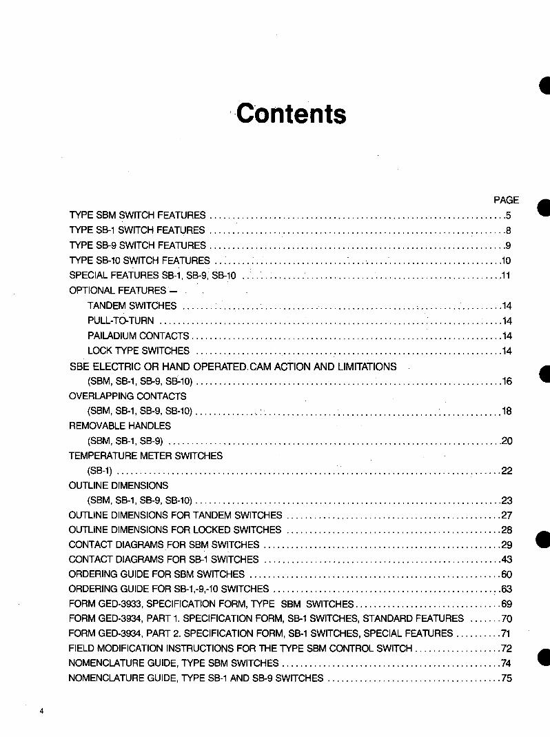
I
PAGE
TYPE SBM SWITCH FEATURES 5 -TYPE SB-1 SWITCH FEATURES 8
OPTIONAL FEATURES-_
SBE ELECTRIC OR HAND OPERATEDCAM ACTION AND LIMITATIONS
OVERLAPPING CONTACTS
REMOVABLE HANDLES
TEMPERATURE METER SWITCHES
OUTLINE DIMENSIONS
TYPE SB-9 SWITCH FEATURES 9
TYPE SB-10 SWITCH FEATURES - middot10
SPECIAL FEATURES SB-1 SB-9 SB-10 middot11
TANDEM SWITCHES 14
PULL-TO-TURN middot 14
PAILADIUM CONTACTS 14
LOCK TYPE SWITCHES _14
(SBM SB-1 SB-9 SB-10) middot16
(SBM SB-1 SB-9 SB-10) middot ~ ~ 18
(SBM SB-1 SB-9) 20
(SB-1) middot- 22
(SBM SB-1 SB-9 SB-10) 23
OUTLINE DIMENSIONS FOR TANDEM SWITCHES 27
OUTLINE DIMENSIONS FOR LOCKED SWITCHES 28
CONTACT DIAGRAMS_FOR SBM SWITCHES 29
CONTACT DIAGRAMS FOR SB-1 SWITCHES 43
ORDERING GUIDE FOR SBM SWITCHES 60
ORDERING GUIDE FOR SB-1-9-10 SWITCHES 63
FORM GED-3933 SPECIFICATION FORM TYPE SBM SWITCHES 69
FORM GED-3934 PART 1 SPECIFICATION FORM SB-1 SWITCHES STANDARD FEATURES 70
FORM GED-3934 PART 2 SPECIFICATION FORM SB-1 SWITCHES SPECIAL FEATURES 71
FIELD MODIFICATION INSTRUCTIONS FOR THE TYPE SBM CONTROL SWITCH 72
NOMENCLATURE GUIDE TYPE SBM SWITCHES 74
NOMENCLATURE GUIDE TYPE SB-1 AND SB-9 SWITCHES 75
I
4
I Construction Features
Escutcheons Two basic types of escutcheons are available the standard and the target The standard type shown on the left is a molded black phenolic material with white lettering for clear reading of the positions A target type escutcheon shown in the middle is normally furshynished on breaker control switches An aluminum front plate houses the target mechanism with a window in the center to show green for the trip posishytion red for the closed position and black for the pull-to-lock position The
a PISTOL GRIP OVAL
Handles Four types of molded black phenolic handles shaped for easy gripping are available with the SBM switch pistol grip oval knurled and lever Any of the standard handles except the lever may be adapted for removable handle keying A fixed handle may be easily removed for replacement by a screw in the front of the handle A white
KEYED
target has a slip action so that it will remain green when the handle returns to NORMAL from the TRIP position and red when it returns from the CLOSE position This shows the operator the last operation of the switch
On the right a modified standard is shown with keyways for use with a removable type handle
Aluminum circuit designation plates are available for all three types
4KNURLED LEVER
pointer furnished with the handles (except the lever) and mounted near the escutcheon give a clear identishyfication of the position that the handle is in For match and line up with SB-1 switches type SB-1 pistol grip oval knurled and round handles can be furshynished for use with SBM switches
Cams and Contacts The silver to silver contacts of the SBM switch are of double-break design as seen at left which reduces arcing and subsequent pitting of contacts Each contact is operated by a double surface cam one surface for closing the other surface for opening This construction provides opening and closing action not dependent on springs
Keyed Escutcheons and Removable Handles -The removable handle commonly used in synshychronizing switches can be made to be reshymoved in any one of the eight positions There are three keys set in front of the handle so that they fit the designated keyways in the escutcshyheon in a desired position The escutcheon can be keyed so that a handle is interchangeshyable or non-interchangeable with another switch If this is desired the catalogue number of the other switch and the position in which the handle is to be removed must be given The removable handle is not furnished with the switch but as a separate item
-Slip Cams The slip cam is basically used on breaker conshytrol switches The slip action enables a contact to remain closed or open after returning to the normal (12 oclock) position from either the CW or CCW positions
I
I
6
I
- Positioning Contacts of the SBM switch are positively positioned by a detent wheel mounted on a square shaft and acted upon by a springshyloaded roller arm If the shaft of the 45deg switch is not rotated more than one-half the distance between positions it will snap back to its prior position If rotated more than half the distance between positions it will snap to the next posishytion The 90deg switch has this same positive detent action when in position but the snapshyping action is not as prominent Up to eight positions are available with 45deg or 90deg between positions
-Terminal Connections Terminal connections are brought to the corners of each stage allowing screw connections to be made over a large angle This angular displacement of connection points allows the switches to be mounted on three-inch centers or less
Jumpers Jumpers are furnished assembled where required on all standard listed switches For special switches or unshylisted switches separate jumpers can be ordered-
-~ 1T)
Jumper Jumper 307V515P1 307V512P1 (Same Stage) (Adjacent
Stage)
Contacts Positions Handle End 3 2 1
1 X
o-t I-ltgt egt-11-ltgt X2
o-tl--0 X3 X
Break-Before-Make Contacts Contacts on SBM switches are normally non-overlapping (break-before-make) This sequence is illustrated above which shows that contact No 1 opens before contact No 2 closes
Another normal function is illustrated by contact No 3 which is shown closed in two adjacent positions When switching between these positions this contact will always remain closed
Spring Action Torsion springs return the switch handle to or towards the 12 oclock or No 3 position The travel of the handle is limited to 90deg to either side of posshyition 3 The switches may be furshynished with spring return both ways or only one way with maintaining action in the opposite direction You can also have spring return from posishytion No 1 (9 oclock) to position No 2 (10 oclock) andor spring return from position No 5 (3 oclock) to position No 4 (2 oclock) with maintained action in the other positions Torsion springs are housed in the rear half of the posishytioning chamber There is no need to modify the chamber to accommodate the springs
Add-A-Stage A one-half inch exentsion is provided on the rear of all switches with one to eight stages This extension enables a maximum of two adshyditional stages to be easily and economically coupled to the existing switch in the event more contacts are required Maximum number of stages including Add-A-Stage unit is 10 (20 contacts)
I I IContacts Handle End
i~IC~ cu tNrt) Oodj I xx xxxx X~inimiddot 2 XXX 3 X xx xxxx~1661 4 xx X
xx xx5 X xx~fl11bull 6X xx
Overlapping Contacts Overlapping contacts (make-before-break) contribute to the versatility of the SBM switch
Typical overlapping contacts are shown on model switch 10AA009 The asterisk () indishycates an intermediate (non-feel) position and shows the contacts overlapping In the 10AA009 when turning from the OFF position to reading position 1 (Phase 1) contact 2 doses at the intermediate position and before contact 1 which remained dosed through the intermediate position opens
Pull-To-Lock A pull-to-lock mechanism is designed for spring-return switches When the handle is turned to the 9 oclock posishytion it can be pulled out and locked in that position When the handle is pushed in the handle spring returns to the normal position This pull-to-lock feature does not actuate contacts but merely prevents the spring return of the handle
7
I Contacts numbered for easy identification
Circuit designation plate is marked for easy identification of switch functions
Good selection handles
Escutcheon plates of pershymanent-finish molded material are neat in appearance and uniform in size
Front aupport spaces body of switch ~ inch from rear of the pane allowing ample room for inaerting leads into the switch
Protective cover (not shown) completely covers all live parts meets NEMA 1 requireshyments for panel mounted switches
Type SB-1 Switch With Cover Removed
SB-1 Switch Provides Flexible Dependable Control for
Electrically-operated Equipment Type SB-1 switches are rotary camshyoperated devices for the control of electrically-operated circuit breakers small motors magnetic switches and similar devices and for the transfer of meters instruments and relays The Type SB-1 switch has molded cams assembled on a square shaft to prevent slipping Rotation of the shaft moves cams directly against contact arms so that positive high pressure results at the contact Contact action is not dependent on springs
Silver-To-Silver Contacts Silver-to-silver contacts operate with
a positive wiping action to provide lowshyresistance current flow Contacts can be removed independently of other switch parts Barriers between adjacenl conshytacts prevent arcing between circuits The switch complete with cover can be obtained with up to 16 stages two electrically separate contacts per stage and for mounting on panels from 1e to 2 thick The panel thickness should be specified when the switch is ordered if it is not the switch will be furnished for mounting on panels up to frac34t thick The SB-1 switch which has a standard insulating cover meets NEMA I requireshyments for panel mounting
Standard Parts Flexibility and low initial cost are the results of standardizing a basically -simple design Standard SB-1 switches are available for most applications For special applications switches can be built from standard parts The long~ wearing cams positive wiping action of silver-to-silver contacts and positive contact opening and closing action all contribute to a switch which is high in quality and will give you many years of dependable service
SB-1 is recognized under the component proshygram of Underwriters Laboratories Inc
I
8
I
Silver-to-siver contacts-opershy Permanent-finish molded es-ate with positive wiping action cutcheon
Contacts numbered identification
for easy Large pistol grip recommended _
handle is
Heavy-duty shunt connections can withstand millions of conshytact operations
Heavy-duty posilionfng wheel is held in place by compresshysion spring to assure positive positioning Type SB-9 Switch with Cover Removed
Removable cover (not shown) encloses all live parts
SB-9 Control Switch Designed for Highly Repetitive Service
-
-
The Type SB-9 switch for heavy-duty service is used where repetitive operashytions run into many thousands per week The SB-9 switch is similar to the SB-1 except that it has a more positive posishytioning device better insulation to ground and more substantial bearings The contact development diagrams for specific applications follow the same general form as for the SB-1
Ratings
Type SB-1 9 amp 10 switches are rated 600 volts 20 amps continuous or 250 amps for three seconds The interruptshying rating depends upon the voltage and character of the circuit and the number of contacts connected in series as
Circuit Volts 1
24 D-c 6
548 D-c
25125 D-c
75250 D-c
25600 D-c
115 A-c 40
220 A-c 25
440 A-c 12
Inductive Circuit Non-Inductive Circuit
Number of Contacts
2 in Series 4 in Series2 In Series 1 4 in Series
Interrupting Rating in Amperes
20 430 30
1540 3 2525
62511 25 2 95
7 1752 8 65
135 15 35 12545
75 24 50
12 25 4050
1225 5 20
1512 104indicated in the table Contacts can be 550 A-c 6 paralleled when current exceeds 20
Values of inductance equal to that of the average trip circuit For circuits having high values ofamps inductance refer application to your General Electric representative for recommendations
SB-1 amp 9 are recognized under the component program of Underwriters Laboratories Inc 9
Removable cover (not shown) Lateral stage contacts open Rotary stages contacts open encloses all live parts and close with push or pull of and close with rotation of
handle handle left or right
Molded escutcheon plate has durable finish and clear markshying
Type SB-1 oSwitch Without Cover
Lateral contacts give SB-10 switch increased versatility
The SB-10 Switch contacts The lateral contacts which The S8-10 switch is similar to the SB-1 provide two electrically separate and switch except for the addition of lateral mechanically independent switches in
Lateral action of SB-10 switch One Lateral Stage
Pull to open contacts 1-2 Maintaining or spring return in or out Pull to close contacts 1-2 Maintaining or spring return in or out
Two Lateral Stages Pull to open contacts 1-4 Maintaining or spring return in or out Pull to close contacts 1-4 Maintaining or spring return in or out Pull to open contacts 1-2 and close 3-4 Maintaining or spring return in or out
Three Lateral Stages Pull to open contacts 1-6 Maintaining or spring return in Pull to close contacts 1-6 Maintaining or spring return out Pull to open contacts 1-4 and close 5-6 Maintaining or spring return in Pull to open contacts 1-2 and close 3-6 Maintaining or spring return out
Four Lateral Stages middot Pull to open contacts 1-8 Maintaining or spring return in
Pull to close contacts 1-8 Maintaining or spring return out Pull to open contacts 1-6 and close 7-8 Maintaining or spring return in Pull to open contacts 1-2 and close 3-8 Maintaining or spring return out Pull to open contacts 1-4 and close 5-8 - Maintaining or spring return in or out
Pull to open denotes the same contact action as push to close Pull to close denotes the same contact action as push to open
-
one device are located at the handle end of the switch The lateral contacts operate independently of the rotary I contacts There may be as many as four stages of lateral contacts (two contacts per stage) The lateral action capabilities of SB-10 switches are given in the table The maximum number of stages including rotary contacts is 12 Lateral contacts on the same stage must open and close together There are only two lateral positions IN or OUT Contacts may be closed in either position A spring can be furshynished so that one of the positions is momentary Rotary contacts may have a spring to return the switch to neutral rotary position When a switch is furnished with both lateral and rotary spring reshy -turn the lateral spring can be loaded in the neutral rotary position only Interlocks may be provided so that the lateral action can be made in one or more rotary positions Interlocks may also be provided to prevent rotary action in the IN or OUT positions or to permit rotary action in both the IN or OUT positions The same types of fixed handles and escutcheons used on S8-1 switches may also be used with the SB-10 switches -Drilling dimensions are the same as the SB-1
silver contacts
Barriers between adjacent conshytacts prevents arcing between circuits
10
bull Special Features se-1 9 10
-
-
PositionsA The maximum number of positions is 12B Position locations and throws are availashyC ble as shownD
E F
Handles
A Round 6047044-1 B Oval 6046075-1 C Radial 6047043-1 D Knurled 6079120-1
Handles Seven different types of fixed handles are shown The handles are designed for durability comfortable grip and pleasing appearance An arrow is embedded in the oval and pistol-grip handles for visual aid in positioning A white pointer is furnished with the knurled and round handles To prevent inadvertent operation of equipshyment by unauthorized persons a removable type handle is available for the SB-1 or SB-9 switches The removable handle is keyed to fit the escutcheon in a specific position All but the radial and the lever type handles can be furnished with keyed shanks as removable type handles The handle can be removed in any one or two positions and such positions should be specified when the switch is ordered
Escutcheons The escutcheon is made of molded black phenolic material with white lettering for clear reading of position labels
G
E Large Pistol Grip 6208137-1 F Lever 6248034-1 G Pistol Grip 6046074-1 H Removable Oval
Types of escutcheons 1 The standard type C or E or F above is used when all positions are at the horishyzontal or above 2 The round type A or D above is used when there are positions below the horishyzontal
3 A target-type escutcheon B amp G above normally used on breaker control switches has a red and green target to indicate the last position to which the switch was turned Pull-to-lock target esshycutcheons are shown to the right (Note that maximum throw is 75 degrees counter-clockwise and 45 degrees clockwise)
4 Both the standard and the round type escutcheons can be furnished with keyshyways to interlock with the removable type handles so that the handle is removable only in a specific position
A separate circuit designation plate when furnished is mounted at the top of the escutcheon and is easily removable
2 POSITIONS 90deg APART bull
2 TO 4 POSITIONS 90deg APART 83
2 TO 5 POSITIONS 37 frac120 APART
2 TO 6 POSITIONS 60deg APART
2 TO 8 POSITIONS 45deg APART
2 TO 10 POSITIONS 36deg APART
2 TO 12 POSITIONS 30deg APART
Handle positions
A B
C
11
I Special Features ccoNT)
CLOSING CAM FOR ----H---t----- NO 2 CONTACT
CAM OPERATED CONTACTS
(FIG 10A)
Contacts and Jumpers Rotary contacts on SB-1 9 and 10 switches are normally break-beforeshymake Over-lapping contacts makeshybefore-break) are available and are used basically in ammeter switching applishycations Slip contact operation is availshyable for breaker control application Moving contacts are cam operated for positive opening and closing (Fig 10A) Stationary contacts are assembled on a common support mounted at the top of the switch for easy replacement Three types of stationary contacts are availshyable (Fig 10B)
A Electrlcally common with center binding post which affords single-break single-pole double-throw operation for two electrically common circuits
B Electrically separate Each stage affords single-break single-pole service for two electrically separate circuits
C Electrically common without a center binding post affording two contacts for double-break action Greater switch flexibility can be achieved by use of jumpers (Fig 10C) Four difshyferent types are illustrated When jumpers are ordered with the switch they are supplied unassembled without additional cost They may also be purshychased separately and assembled on existing switches
Spring Return Action
3
Spring return can be adapted to any SB-1 9 and 10 switch providing these limitations are adhered to 1 The handle must return to or toward the 12 oclock position but not pass it 2 The maximum throw is 90deg to either side of the 12 oclock position 3 You cannot have a maintained posishytion pas a spring return position Example if spring return from pos 2 to pos 3 is desired pos 1 cannot be a maintained position However the funcshytional equivalent can be obtained by specifying a pull-to-lock action in place of the maintained position Spring return from both directions to NORMAL or spring return with mainshytained action can be provided on the same switch Example A Spring return from position 1 and 2 to 3 maintaining in positions 3 4 and 5 or spring return from 5 to 4 to 3 maintaining in positions 1 2 and 3
A
B o---U---o o---U--o
C o-lHt--o
(FIG 10B)
atgt flt ~ (SAME STAGE) (ALTERNATE STAGE) 307V512PI 6244177PI
ff Qnnu() 6149141 Pl 1455504PI (ADJACENT STAGE) (FLEXIBLE)
(FIG 10C)
IB A five position switch can be furshynished with partial spring return from positions 1 to 2 and or 5 to 4 with maintaining action in the remaining positions SB-9 only)
Pull-To-Lock A pull-to-lock may be added to lock the switch against spring return action Lockshying is accomplished by pulling the handle out in the pull-to-lock position to engage a latch which arrests the spring return The switch will remain in the locked posshyition until the handle is pushed in Note This pull-to-lock feature does not actuate contacts when pulled
The following are standard pull-to-lock combinations available with a standard target type escutcheon -A Spring return from all positions to NORMAL except when middot locked pull handle to lock at 75deg CCW
B Spring return from 45deg CW and CCW to NORMAL pull to initiate locking at 45deg CCW then turn to 75deg CCW and pull-to-lock
C Spring return from 45deg CW and CCW except when pulled-to-lock at 45deg CCW Special pull-to-lock switches can be I furnished however spring return action from the pull-to-lock position is reshyquired
12
Optional Features se-1 9 10
PullTo-Turn A pull-to-turn feature can be incorporatshyed in a SB-1 or SB-9 switch to prevent accidental operation The handle is locked against turning when it is in the in position and must be pulled out to unlock and turn to the selected positions it is equipped with a lateral spring that pulls the handle to the in position
The handle can be locked against turning in one or more positions or can be free to rotate between certain positions while in the in QOsition
Locks Two different types of locks are availshyable Each allows the switch to be locked in one or more positions One lock is built into the operating handle The other lock is separately mounted on the panel above the switch and when necessary can be coordinated with a Kirk key-interlock scheme When it is necessary to lock switches in more than one position a 45-degree space must be provided between adjashycent locking positions Therefore eight is the maximum number of lock posishytions that can be furnished
Rotary spring action is not recommended with pull-to-turn because the lateral spring may not always overcome the roshytary spring and automatic return to neushytral may not always occur
Push-To-Turn The push-to-turn feature is almost the exact opposite of the above-shown pullshyto-turn feature and the same restriction as to the use of rotary spring return applies
Palladium Cltgtntacts Available for temperature meter switches Palladium contacts have a constant resistance factor which is necessary because calibrated leads are normally used in temperature meter cirshycuits Silver contacts would result in a variable resistance factor and cause fluctuations in meter readings
13
Hand And Electrically Operated Switch Type SBE
~middot-
DESCRIPTION The SBE switch is basically a hand or electrically operarted SB-1 switch The electrical operation is acshycomplished by the use of a high-torshyque vdc motor regulated by the use of an electronic controller and atshytached to the switch by a clutch mechanism
The SB-1 switch portion consists of up to twelve customer-usable silver to silver cam operated contacts with a positive high pressure self-wiping action See Figure 2 for typical conshytact arrangement
The SBE is available for mounting on panels 1 16 to 1 8 thick
APPLICATION SBE switches can be used in place of
the manual-only circuit breaker control switches which can allow remote SCADA supervisory control Even though the SBE switch is longer than the standard SB-1 breaker control switch the panel space for either device is the same Therefore retrofitting manual-only locations with reshymote control is relatively easy
A typical contact wiring diagram is shown in Figure 2 Additional contacts can be used with a white indicating light or alarm to indicate a protective (not operator) trip Also provided are contact to be used with an automatic recloser interlock circuit
This same switch may also be used with different position engraving for opshyeration of motor-operated disconnect switches small motor contactors and similar bi-directional devices The applishycation should be checked for operation with a contact dwell time of 1 second in each direction (CW and CCW) when the SBE is operated electrically
BREAKER CONTROL
D$- middotmiddotmiddot- lto
i middot r-
~ ---
CONTACTS POSITIONS HANDLE
END CLOSE NORMAL AflER CLOSE
NORMAL AFHR TRIP
TRIP
1 2 1 X o--tHI--() 2 X
3 4 3 X X OmiddotH-0 o-H-o 4 X
5 6 5 X X o--l 1-o o--l 1-o 6 X X
Fig 1 SBE switch with cover removed
BURDENS For 125 VDC Motor at 150 VDC
bull 1 amp for 200 ms bull 07 amps for the second dwell period
RATINGS Operating Range of 125 VDC Motor Fig 2 SBE switch
bull 785 to 150 vdc Contact Arrangement
CONTACT RATING -NON-INDUCTIVE CIRCUIT INDUCTIVE CIRCUIT NUMBER OF CONTACTS NUMBER OF CONTACTSCIRCUIT
VOLTS 42 4 2 11 INININ IN
SERIES SERIESSERIES SERIES
300 48 DC
40 20030024 DC 60 250
125 DC 400 30 150025050
95 250 DC
250 20 62511026 65
600 DC 80 07 17520075
125015 035135025 045
500 220 AC
2405004000115 AC 500 2502500 120 400
440 AC 2501200 200 550 AC
50 120 120 15 0600 40 100
The interrupting ratings of the conshy The contacts will carry 20 amps conshytacts vary with the inductance of the cirshy tinuously or 50 amps for 1 minute The cuit The values given above for de inshy contacts will close on 50 amps for volshyductivemiddot circuits are based on the avershy tages 600 volts or less age trip coil currents
14
I
I
(i) ---~--------------r---------------r--------125VOC
CLOSE TRIP 52CS(CW) (CCW)tl_ 52CS C
~ NAC NAT rcsTB Tl3 I 0 TB6
52CSJ_ 52CS 522E0 CIRCUJTC NAC CLOSE CJRCUITS
TBS52 b
PROTECTJVE TRIP ALARM
ANO OR INDICATING
LIGHT
52 a
~ 5CS 52 ~CNAC TC
AUTO RECLDSER INTLK
Fig 3 Typical Control Circuit with SBE (286A3555)
(-) ___j____________j______________________125VOC
15
The operating cam of SB-1 -9 and Cam Action and Limitations -10 switches is based on a 30-degree cut to each side of the center (Fig 1 ) A standard-profile cam will fully open or close a contact in 30 degrees making or breaking 15 degrees from
Fig 1 Operating cam for SB-1 -9 and -10 switches
NO I CONTACT r==== a OR
COMMON OPENING CAM
coR CLOSINGFRONT VIEW HANDLE CAM FOR NQIIN 12OdegCLOCK POSITION CONTACT NOT SHOWN
Fig 2 Composite view of contacts and cams
C B
Fig 3 Individual arrangements of cams in Fig 2
( BACK)POSITIONCONTACTS VIEW HANDLE END
3 2 I
1 I Xo-u--0-11--0 I 2 X X
Fig 4 Contact arrangement back view
the fully open or fully closed position Fig 2 is a composite view of I
contacts and cams assembled on a stage of a switch This figure shows that odd-numbered contacts are on the right side of the switch (viewed from the front) and are closed by the C cam Even-numbered contacts are on the left side and are closed by action of the A cam Both contacts are opened by the B cam
Fig 4 is the contact diagram for Fig 2 with Fig 3 showing the individual arrangement of cams
0 n e cam limitation must be -considered when the switch rotates 180 degrees or more Referring to Fig 3 you see that when cam B is rotated 180 degrees the same relationship occurs between the periphery of Cam B and the contact mechanism of Conshytact No 1 as occurred between the periphery and contact mechanism of Contact No 2 before rotation thereshyfore whatever happens to one contact at any point in the switch rotation must happen to its companion contact in the same stage when the switch is rotated 180 degrees Fig 5 shows the diagram of an unworkable and a I correct arrangement
When contacts on the same stage cannot be arranged to avoid this 180-degree cam limitation one contact per stage is used (See Fig 6) On five-position switches 37-1 2 degrees can be used instead of 45 degrees to avoid this limitation
SLIP CAMS Slip cams increase the flexibility of
the switch They allow a contact to be closed in the NORMAL position after returning from either the CW or CCW position and also to be open in the NORMAL position after returning from the opposite direction This -action is accomplished by allowing the cam to slip 45 degrees as shown in Fig 7 Once the shaft actuates the cam the shaft wil I then slip 45 degrees in the opposite direction without actuating the cam
This type of action is commonly used for circuit-breaker control applishycations Fig 8 shows a breaker conshytrol switch Model 16S8182 which has slip action on Contacts 7 and 8 With this slip action there are some -limitations Three of these limitations and how to avoid them are shown Limitation No 1 does not apply to the SBM switch because of the indepenshydent cams for each contact
16
I
Cam Action and Limitations (Contd) INCORRECT CORRECT
POSITIONS (BACK VIEW) POSITIONS (BACK VIEW) ICONTACTSCONTACTS HANDLE END HANDLE END8 7 6 5 4 2 I3 8 7 5 4 3 2 I6
I 2 o-H-0 0-11--0
3 4 o-n-o o-11--0 5 6ltgtbullHo o-H-o 7 8 o~ o-H-o
Fig 7 Diagram showing
( I NCORRECTl
2 2N IN I
I 2 11 XX o-H--o o-H-o I 2 X X- (CORRECT)
2N IN I2
I I X X o-j l--0----
4
1-ltgt--lkgt 4 X X
Limitation No 1 (SB-1 -9 amp -10)
A slip contact and standard-
I
2
3
4
5
6
7
8 X X
X X
X
Fig 5
I
7
SLIP
STANDARD
X X
5
ESCUTCHEON ( FRONT VIEW)
X
Diagram
3
4
I 2 o-O-o o1-o 3 4 o-H-o o-H-o 5 6o-H-0 o1-o 7 8 o-11-o ~l-0
I
2
3
4
5 6
7 8 X
X
X
X
X
X
X
X
of unworkable and correct arrangement
POSITIONS (BACK VIEW CONTACTS HANDLE END 8 7
ol--0--I
~k)
~l-o-1
1-o-11-0
I
4 X X 5X
8
6 5 4
X
X
X X
3
X
X Fig 6 Contact arrangement to meet cam limitations
CONTACTS HANDLE END
I 2 0-11-0 rH-o
1~4o-1 ~ 5 o-r- __1ry
I~ ao-1 o-j~
I
2 3
4
5
7
8
45-degree slip action of cam Fig 8 Breaker control switch model 16SB182
( INCORRECT l
3 3N
I 2 11 ~1--o o-U-o 12
(CORRECT)
I 2 I )gt-i l-0 0- 2
3~ f--0 0- 4 ) 4
3 3N
X X
2N
X X
2N
X X X X
2
X X
2
X X X X
I
I
X X
2 I
X
X
37
4 5
ESCUTCHEON (FRONT VIEW)
POSITIONS
Close
X
X X
X X
Norm Norm ofter ofter Trip close trip
X X
X X
X X
( INCORRECT)
2
I 2 I I o-n--o o f--0 I2
( CORRECT)
2
I 2 )(jgtmiddotH--0 0
~ 4_I f--0 o-f gt
I 2
3
4
2N
2N
X X
IN
X X
IN
X X X X
I
i X X
Limitation No 2 ( SBMS81 -9 amp -10)
contact On a 4-position pull-to-lock switch tht A contact cannot be closed in the
Limitation No 3 (SBM SB--1 -9 amp -10)
cannot be on the same stage as shown in slip contact cannot be closed in the 2N and normal after position without also closing in the top diagram 2 positions (As shown in the top diagram) the position itself as shown in the top
A stage must be added and contacts split without closing in position 1 To accomplish diagram To accomplish this a stage must be up as shown in the bottom diagram one this a stage is added and the contacts are added and the contacts set up as shown in contact per stage (Does not apply to SBM) connect in series as shown in the bottom the bottom diagram with the contacts
diagram placed in series by jumpers Jumpers required are shipped loose with the switch
17
Overlapping Contacts mediate position is identified by an degrees between positions by use of aGENERAL X in the block above this position in special cam
Contacts on Type SB switches are the operating requirement table ConshySB-1 -9 AND -10 SWITCHESnormally non-overlapping (breakshy tacts 1 and 2 are shown overlapping in
before-make) This sequence is the intermediate Positions 4 and 6 illustrated in Fig 10 which shows that Contact 2 is shown making in intershyContact No 1 opens before Contact mediate Position 4 before Contact 1 No 2 closes when turning from breaks when going from Position 3 Position 1 to Position 2 Another (OFF) to Position 5 (PHASE 1 ) and normal function is illustrated by Contact 1 will make before Contact 2 Contact No 3 which is shown closed breaks when going from Position 5 to in two adjacent positions (Positions 2 Position 7 and 3) When switching between these Figure 12 illustrates an ammeter positions the contact will always switch for three independent current remain closed There are some circuits transformers (similar to Model where this action is not desired such 10AA013) This switch also has overshyas switching current transformers to an lapping contacts and intermediates at ammeter Here the contacts must Positions 2 4 6 and 8 however the overlap (make-before-break) to overlapping action takes place between prevent damaging the meter the intermediate position and the
actual position The X on the lineSBM SWITCH between the positions of thl contacts
To get this overlapping action on identifies this action When turning the contacts 90 degrees between from Position 5 (PHASE I) to Position pos1t1ons is required Figure 11 7 (PHASE 11)Contact 1 makes before illustrates an ammeter switch (similar Contacts 2 and 3 break Also Contact to Model 10AA009) with overlapping 2 and 3 break before Contacts 4 and 5 contacts The overlapping action takes make and Contacts 4 and 5 make place in the intermediate positions before Contact 6 breaks All this (Positions 2 4 6 and 8) The inter- action takes place within the 90
Fg 10 Typical non-overlappingPOSITIONS HANDLE END CONTACTS
(break-before-make) sequence 3 2 I I 2 I Xo-H-o o-H-o 2 X
3 X X~1--o AMMETER
OFF
INTER POSITION
~ 7 IJltI 5 1( 3 I
3
2
AMMETER CONTACTS POSITIONS OFF ODD EVEN 8 7 6 5 4 3 2 I
3 o-U-o o-H--o I
2 X X rx ~ X X -~-
(V 1
2 o-U--ltgt ltgt41--o
3 4 oc
kX
o-11--o ltgt41--o 5 6 x
)( ~
Kx Iv
o-0--o ltgt41--o 7
8 X gtL00 -
~-
o-11--o o-H-o 9 ex
Basically the overlapping action is the same as with the SBM switch but Iit is not limited to positions which are 90-degrees apart
To get a make-before-break action as shown in Fig 13 a minimum of 37frac12 degrees between positions is required To get a make-before-break as shown in Fig 14 a minimum of 60 degrees is required The flexibility of the SB-1 -9 and -10 switch allows the comshybination of 37frac12 degrees and 60 deshygrees in the same switch to give you an ammeter switch which reads as many as six independent current transshy -formers with either 1 or 2 0 F Fs (see Fig 15)
A special contact sequence which requires a contact to close in adjacent positions but to open momentarily between them is shown by Contact 1 in Figure 16 A minimum of 60 degrees between positions is required When less than 60 degrees is required use two contacts in parallel as shown in Fig 17
I INTER POSITION
7531 POSITIONS
ODD EVEN CONTACTS
4 3 2 I
I
8 7 6 5 X XX XX X Xo-11--0 o-H-o 2 XX X
3X XX X XX Xo-H--o o-t f-o 4X XX
sx X X X XX Xo-11--o ltgt41-o 6 X XX
Fig 11 Overlapping contacts for SBM ammeter-type switch connected at end of secondary -
Fig 12 Overlapping contacts for AMMETER POSITIONSCONTACTS SBM ammeter-type switch with three HANDLE ENO Inter Inter I3 22 3 independent circuits I X IX
2 X XX Xt~~ 3 XXH~ 4 X XX X
Fig 13 Overlapping contacts for SB-1 ammeter-type switch 18 connected at end of secondary (two current transformers)
2
Overlapping Contacts (Contd)
AMMETER CONTACTS HANDLE END
3 ~hgt--4~
~1--o
~~~ ~~
~hgt--4~
~rltgt
CONTACTS HANDLE END
6 2 I o-H-~
5 3 4
3~ 40- 1-o
51~ 6o-j rltgt
7 ~ 8 ~ I-ltgt
I
2
3
5
6 7
9 10
II
I
3 4
5
6 7 8
3
X
X
X X
6 5
4
6 X
X
POSITIONS
X X
XX
X X X
X
X
X X X
X
AMMETER OFF
I 2
3
2
X
X X
X
X
X X X
X
XX X X
X X
XX
I
X X
X
X
CONTACTS HANDLE END
POSITIONS
5 X
X
4
X
X
3 X
X
2 X
X
Fig 14 Overlapping contacts for SB-1 ammeter-type switch with three independent circuits
I X
X
Fig 15 Overlapping contacts for SB-1 ammeter-type switch with six independent circuits
POSITIONS - BACK VIEW u
u 0
Fig 16 Special contact sequence which requires one contact to be closed in every handle position but to open momentarily when switching
Fig 17 Special contact sequence POSITION - BKVIEWCONTACTSwhich requires one contact to be
HANDLE END 876543218 2closed in every handle position but to IX XX X7 3open momentarily when switching 2X XX Xhowever when less than 60 degrees 6 4
5 X X X Xbetween positions is required two ~ontacts are connected in parallel X X X
19
To prevent operation ofequipment by unauthorized persons switches with removable handles are available The handle is keyed to a specific escutcheon to be inserted and reshymoved in a designated pos1t1on Handles can also be mutually keyed to other escutcheons so that they are either interchangeable or non-intershychangeable with other switches
This feature is available for SBM SB-1 and SB-9 switches but ordering procedures differ
SBM SWITCHES
0 3 0
5I 0 6 0 7 0
Fig 18 SBM switch keyed escutchshyeon with eight available keyway locashytions Keyways 1-3-5 are shown
The keyed escutcheon on the SBM switch ( Fig 18) has eight possible keyway locations Three are normally used and are assigned by the factory The choice is influenced by several factors
a If the handle is to be intershychangeable with that of another switch the position in which each handle is to be removeable must be considered
b If the handle is to be non-intershychangeable the keyways assigned to other removeable handles in the same panel must be considered
c If no special instruction is given by the customer when he orders the factory will assign keyways at random if more than one SBM switch has a removable handle they will be keyed to be non-interchangeable
A removable handle is furnished as a separate item not with the switch it operates because in some cases the single handle operates many switches The handle is keyed so that it will fit through the keyways on the escutcheon in a specific position
When ordering a removable handle specify the type the position in which it is to be removable and the switch or switches it will be used with The factory will assign the handle To
Removable Handles TABLE 1 Nomenclature guide for SBM removable handles
1st 2nd 5th Number 1st 2nd 3rd 4th
Letter LetterNumber NoNo No
Action ofRemovable Common Escutcheon Type Handle
Rotation Keywaysin Position Code
W=CWampCCW 11 = Knurled 1 w 1 1
L = CCW (special) thru thru thru2 = Oval thru
R = CW (special) 8 grip
3 = Pistol 8 88
Example 1 21WW135
This oval handle has keys at positioos which when it is in position 1 or nine oclock will line up with escutcheon keyways 1 3 and 5 It is therefore removable in position 1
identify SBM removable handles see Table 1
SB-1 amp SB-9 SWITCH
The keyed escutcheon for the SB-1 amp
SB-9 switch is normally furnished with two keys and three keyways (see Fig 19) The circumferential location of the keys and keyways will vary depending on the location etc in which the handle is to be removable The location of the keyways is assigned by the factory
Table 2 gives a list of standard keyed escutcheons and the proper removable handle for removing the handle in both the vertical ( 12 oclock) position and 90deg ccw (9 oclock) pos1t1on Escutcheons 6016164P-2 thru P-14 are used on switches if the throw does not exceed 90deg on either side of the vertical ( 12 oclock) position and P-23 24 and 25 are used when the throw does exceed this limit
0
Fig 19 SB-1 escutcheon for use with removable handle
-
-Oval handles 16S81CC1 thru 32 are
listed with direction and degree of throw from the positions in which they are removable The code letters A thru Z in the left hand column identify the escutcheons used on the basic unlisted switches
I Example 16S81AB300S~M3Y the 2nd form letter ~ identifies a keyed escutcheon 6016164P 3
When a special keyed escutcheon is required different from any of those listed the code letter X is used followed by the part number
Example 16S81AB300SX34M2Y
All keyed escutcheons will now have the part number stamped at the bottom left hand corner instead of the code letters previously stamped at the bottom righthand corner If the code letter or other indentification is deshy -sired it will be stamped at the bottom righthand corner by requisition only (three characters maximum) The 16S81CC oval type removable handle will now have the form number only stamped on the lower face of the handle Those removable handles which have metal shanks (6119745G) will have the group number stamped on the shank When a switch with a Ikeyed escutcheon for a removable handle is ordered be sure to specify the position in which the handle is to be removable If an existing handle will be used give the number of the existing handle
20
Removable Handles (Contd)
I TABLE 2
Model Number
Code Escutcheonbull Handle Throw
Handle Removable in Vertical Position
I
A 6016164P3 16S81CC1 A 3 CC18
B 4 CC2 4 CC19
C
B
5 CC3 5 CC15
D
C
6 CC4 D 6 CC11 D 6 CC22 D 6 CC27
E 7 CC5 7 CC12E
E 7 CC13 7E C20 7E CC25
F 8 CC6 F -8 CC14 F CC248
CC7G 9 G 9 CC8
CC17G 9 G 9 CC26 G 9 CC29
9 CC21
H
G
10 CC23 H 10 CC9 H 10 CC10
10H CC31 10H CC32
J 23 CC18
y 24 CC19
z 25 CC21
Handle Removable 90deg CCW
K 6016164P11 16S81CC1 K 11 CC18
L 12 CC2 12L CC15
M 13 CC3 13M CC15
N 14 CC11 N 14 CC27
14N CC4 14N CC22
SpecialX
135deg cw 360deg
135deg cw 360deg
135degCW 360deg
135deg cw 45degCW amp ccw 45degCCW 360deg
45 cw 75degCW 45degCWamp ccw 360deg 75degCCW
45degCW 45degcw amp ccw 36QO
Type SB-1 and SB-945deg CW I Eng 45deg CCW R Eng 45degccw 135deg CCW 45degCW 360deg OFF
360deg 45deg CW I Eng 45deg CCW R Eng
1
)j~bullbullo+ 45degCW 45deg ccw
I 360deg
360deg
360deg
135degCW 360deg
135degCW 360deg
135deg cw 360deg
45degCW amp ccw 360deg 135deg cw 45degCCW
The P number (3 4 etc) is used as the part Fig 20 Typical removable handles number in the text and escutcheons
21
I
Temperature-Meter Switches
Temperature-meter switches are Fig 21 shows a temperature-meter circuit with a TEST and an OFF furnished with palladium contacts switch Model 16SB 1 CE52 reading position On a three-wire circuit you which have a constant resistance factor This is necessary because calibrated leads are normally used in a temperature-meter circuit and silver contacts would result in a variable resistance factor and cause fluctuation in meter readings
TEST METER Off ~
~ jQr
Ii-2
four RTDs on a two-wire circuit with a TEST and an OFF position On a two-wire circuit you can transfer up to seven coils with an OFF position or six coils with a TEST and an OFF position
Fig 22 shows a Model 16SB1CE55 reading three RTDs
TEMPERATURE METER TRANSFER SWITCH
TRANSFERS TWO WI RES TO FOUR COILS WITH TEST a OFF
MODEL NO 16SBICE52
POSITIONSCONTACTS HANDLE END GI Ill =-C
I-4 i ICs co~ 2~ -
I I X o~ ~~ 2 X
43 3 X XX l-0~ r - 4 X X X
55 Xo-H-~ 6
6-- 1-o X 7 X X X1~LJ 8l-0o-1 r 8 X X X
~ 9 XI 109 II - 1-o 10 X II X X XI 12II
o-i - ~ 12 X XX 115 V A-C SOURCE
X y
FUSES
TEST RESISTOR
C B
4 3 2 DETECTOR COILS IN MACHINE
Fig 21 Temperature meter switch Model 16S81CE52
on a three-wire
TEST METER Off ~
~
can transfer up to six coils with an OFF position or five coils with a TEST and an OFF position When it is required to transfer more RTDs than the maximum for a given switch two switches with a removable handle may be used
TEMPERATURE METER TRANSFER SWITCH
TRANSFERS THREE WIRES TO THREE COILS WITH TEST 8 OFF
MODEL NO 16SBICE55
POSITIONSCONTACTS - 3
- Ill
pound CU
0HANDLE ENO - iC 2 c cl C Ci i I 2 I X 0-1-0-11-0 2 X 3 4 3 X X X 0-l-0-if-0 4 X XX 5 6 5 XX X ltgt-it-o-lrO 6 XX X 7 8 7 Xo-H-ltgt-Hmiddoto 8 X 9 10 9 X XX o-l~r-6 10 X X X II 12 II XX Xo-lkgt-1~ 12 X XX
115 V A-C SOURCE X y
FUSES
TEST RESISTOR
C
3 2 I DETECTOR COILS IN MACHINE
Fig 22 Temperature meter switch Model 16S81CE55
I
22
Outline Dimensions Type SBM Control and Transfer Switches
Hgndi11
li7bull
1-8
Standard ____ Oval SwitchNoof
Stages A B
gbull2
16 1 31 21e 2 4frac12 2v 3 51e 21e
4 51 2v 5 6frac34 2v 6 7 21a
7 7 2v 8 8frac14 21 9 8frac12 2v
10 91a 2v
Knurled
f28
Lever
SHIPPING WEIGHTS
When panel is 1bullthick -add l2to A and B dimensions
Pull-to-Lock Removable Switch Handle Switch
A B A BI I
4) 211 4frac34 3) SJ 27e 5o 3) 5frac34 21a 6 3)
6 271 65a 3) 7) 21 7frac14 3) 7frac126 21o 77e 3)
8) 211 8frac12 3) 8) 21o 91 3) 8frac34 211 91 9) 9 211 9frac34 3)
Approx weights are listed below All weights listed apply to SB switches consisting of one stage Add 6 ounces for each additional stage
Type SBM (1 Stage) 1frac12 lb
(This data is subject to change without notice)
23
---- --- --- --- ---
Outline Dimensions ccoNTgt
Type SB-1 Control and Transfer Switches
(For estimating only) Panel
311
~lt-- Handles 1321--t 1 f-- frac12 drill (3 holes)
T ~~cutcheonmiddotf -~-middot- l--r11
3_] aI 132
-A-_j - 8 -- To1
I Oval I
I I
I I
No of
Stages
Radial
Round 12-8
Ti 1 514 2s 6
7
B
9
10
11
12
13 Locked
14handle
4 15
16
remove cover
SB-1 switch with fixed handles (Outline 116A 130)
Dimension in Inches
Standard Cover
Standard Cover 12 Wires Out Top
and 24 Wires Out Bottom
A I B
5 1316 10116
11 16 20 156
11 136 22 716
13 frac126 25 76
14 1316 28 76
I C
4 frac12
Lorge Cover
Large Cover 24 Wires Out Top
and Bottom
6 116 10 116
4 1116
10 916 19 1116
11frac126 21 316
For spring-return switches when more than three and less than seven contacts close in the normal handle position add frac34 to A and 1frac12 to B When seven or more contacts close in the normal handle position add 1frac12 to A and 3 to B
Note Removable handles are similar to fixed handles and availshyable in all styles except radial and locked They do not alter switch dimensions or panel drilling
SHIPPING WEIGHTS Approx weights are listed below All weights listed apply to SB-1 switches consisting of one stage Add 6 ounces for each additional stage
Type SB-1 (1 Stage) 2 lb (This data is subject to change without notice)
I
I
24
-----
-----
----------
-----
-----
------
-----
---------
---------
---
---
------
---
---
---
---
---
------
------
---
---
---
---
---------------------
---
I
-
No of Stages
I 1
2
3
4
5
6
7
8
9
10
11
12
13
14
15
16-
Outline Dimensions ccoNT)
Type SB-9 Control and Transfer Switches
(For estimating only)
Panel-mounted Type SB-9 switch (Outline 116A139)
PANEL-MOUNTED TYPE SB-9 Dimension ir Inches
Standard Cover 12 Wires out Top and 24 Wires out Bottom
A 8 CI I
41a
51a
61a
71 -~--
71
81a
91a
101a
101e
111a
121a
131a
131e
141a
151o
161
83a
91a
111a
121
141
151e
171
181a
201a
middot211a
231a
241e
261
271e
291a
301e
4frac12
Lorge Cover 24 Wires out
Top and Bottom
A 8 CI I
51a
51
61a
71
81a
81a
91a
10
111a
111e
121a
131a
141a
141e
151a
16 lo
8frac14
101
111a
131a
14frac14
161
17frac14
191a 4l5Ji6
201a
221a
23frac14
251
261a
281a
291a
311a
For spring-return switches when more than three and less than seven contacts close in the normal handle position add frac34 to A and 1frac12 to B When seven or more contacts close in the normal handle position add 1frac12 to A and 3 to B
Note Removable handles are similar to fixed handles and availshyable in all styles except radial and locked They do not alter switch dimensions or panel drilling
SHIPPING WEIGHTS Approx weights are listed below All weights listed apply to SB-9
- switches consisting of one stage Add 6 ounces for each additional stage
Type SB-9 (1 Stage) 3 lb
25
-----
------
----------------
I Outline Dimensions ccoNT)
Type SB-10 Control and Transfer Switches
(For estimating only)
Panel
bull ICx2 16 wide
11or8
n3
-----A----- Panel Ori I ling ---B to Remove Cover (front view)
No of Stoges
1
2t
3t
4t
5
6
7
8
9
10
11
12
Panel-mounted Type SBmiddot10 switch
Dimension in Inches
Standard Cover Large Cover
A B C A B CI I I I I 6frac34
6frac34
7frac12
8frac14
9
9frac34
10frac12
11frac14
12
12frac34
13frac12
Ufrac14
12frac12
12frac12
14
15frac12
17
18frac12
20
21frac12
23
24frac12
26
27frac12
4frac12
12frac347
7 12frac34
7frac34 14frac14
8frac12 15frac34
9frac14 17frac14
10 18frac34 4 15i6
10frac34 20frac14
11frac12 21frac34
12frac14 23frac14
13 24frac34
13frac34 26frac14
14frac12 27frac34
bull Includes both lateral and rotary stages
(Outline 0l65A6122)
SHIPPING WEIGHTS Approx weights are listed below All weights listed apply to Type SB-10 switches consisting of one stage Add 6 ounces for each additional stage
Type SB-10 (1 Stage) 3frac12 lb
(This data is subject to change without notice)
I
I 26
I
-
- ADD 14 TO A amp B DIM
FOR LARGE COVER
NOOF STAGES A B
1 5-116 7-7 16
2 5-1316 8-1516
3 6-916 10-716 - 4 7-516 11-1516
5 8-1 16 13-716
6 8-1316 14-1516
7 9-916 16-716
8 10-516 17-1516
9 11-1 16 19-716
10 11-1316 20-1516
11 12-916 22-716
12 13-516 23-1516
13 14-116 25-716
14 14-1316 26-1516- 15 15-916 28-716
Tandem Switch Outlines
PANEL
frac121 il 11 F--~--F-----F ----A~
B TO REMOVEOUTLINE COVER
NOTE ALL DIMENSIONS ARE IN INCHES
i---------c-------i PANEL
TWO SWITCH TANDEM SB-1
Gear-operated (360deg rotation)
THREE SWITCH TANDEM SB-1
Gear-operated (360deg rotation)
FOUR SWITCH TANDEM SB-1
Gear-operated (360deg rotation)
DRILLING -
C
7-12
11
14-1 2
D
2
5-12
5-1 2
FRONT
E
8-14
11-34
15-1 4
VIEW
F G
3-1 2
a w gta3-12 0w ugt w0 ()u aI ltI Ilt a~
() 0 ua
03-1 2 u ~
N
(This data is subject to change without notice)16 16-516 29-1516
Fig 23 Tandem-switch outline 27
Outline Dimensions for Locked Handle Switches
3116 DI A--- + -r--------
~ 1gttl~1
f DIA--1-4-----fyen-l 3
t 32-rDIA(3l___ PANEL DRILLING (FRONT VIEW)
l middotcbullx2 1
16
WIDE
t~omiddot--1 32 FOR frac14-ifrac14 PANEL
~ FOR I a 2 PANEL
~ FOR 1-t PA~~~-----~
~18
11 TO REMOVE COVER
SB-switch with Yale Lock above the switch ForA and B use standard dimensions plus D depending on panel thickness
SB-9 SWITCHES
STANDARD DIMENSIONS IN INCHES
STANDARD COVER 12 WIRES OUT TOP LARGE COVER
NOOF AND 24WIRES 24WIRES OUT STAGES OUT BOTTOM TOP AND BOTTOM
A B C A B C
1 4-78 8-38 5middot18 8-58
2 5-58 9middot78 5middot78 10middot18
3 6-38 11-38 6-58 11-58
4 7-18 12-78 7middot38 13middot18
5 7-78 14-38 8-18 14-58
6 8-38 15-78 8middot78 16middot1 8
7 9-38 17-38 9-58 17-58
8 10-1 8 18-78 10-38 19middot1 8 4 12 4 15169 10-78 20-38 11-18 20-58
10 11-58 21-78 11-78 22-18
11 12-38 22-38 12-58 23-58
12 13-1 8 24middot78 13middot38 25-1 8
13 13-78 26-38 14middot1 8 2amp58
14 14-58 27-78 14-78 28-1 8
15 15-38 29-38 15middot58 29-58-16 16-18 30middot78 16middot38 31-18
(This data is subject to change without notice)
28 Fig 24 Dimensions control switches with Yale or Kirk Lock
I
Contact Diagrams for SBM Switch
-I VOLTMETER Source Voltmeter
POSITIONS Fig 25 VOLTMETER SWITCH OFF
0-idouble-pole single-throw ON OFF0Model No IOAAOOI 2X
XKnurled handle
VoltmeterVOLTMETER ~ONTACTI POSITIONSHANDLE - OFF ENDFig 26 VOLTMETER SWITCH ltgt I-
0 double-pole double-throw
2 l5 I ~cModel No 10AA002 2
ltgtl~fo I X 2 XKnurled handle
3 43 Xltgtl~fo14 X
VOLTMETER ONTACTI POSITIONSFig 27 VOLTMETER TRANSFER HANDLE N 3 2 I2 ENDSWITCH three-phase
J -transfers lour wires -shy 8Jffic 3 2 lo- 0
I phase-to-neutral 0 IXltgt1tpifo I XModel No 10AA003
3 Xltgtl~ltgtifoKnurled handle 14 IY IX
VOLTMETER tONTACT5 HANDLEFig 28 VOLTMETER SWITCH
END1 2-3
JPhase-to-phase or _ N-cjffi-phase-to-neutral l)N - Move this-08 c0- jumper0 I X IXModeNo 10AA004 3-phose 3-wirP to 1-2 whenrot xx
connectingKnurled handle 3 X switch 3 ltjgt4w~~ 4 X 3-phose 4-wire (future
alternate connection)
Ivo mete I VOLTMETER ~ONTACTI
HANDLE 4 3 2 I 2 END I ~o 2 6I J u
ucJffiFig 29 VOLTMETER SWITCH 8 c 2 I 04 3OFF 0 4 I- n 4 3Xfour circuits two wires Iltgtl~fo~ XModel No 10AA005 IIX - 5 dltgtI~- 4 -
IX I f6Knurled handle X Iltgtiffdeglo ~ h7 8X IX7ltgti~lo 8 X
x in all contact diagrams denotes contacts closed
29
Contact Diagrams for SBM Switch
DESCRIPTION
VOLTMETER TRANSFER
SWITCH three-phase transshy
fers four wires phase-to-phase
and phase-to-neutral
Model No I 0AA006
Knurled handle
Fig 30
Fig 31 VOLTMETER SWITCH two
three-phase three-wire
circuits Model No 10AA007
Knurled handle
Fig 32 AMMETER TRANSFER SWITCH
three CTs (connect at
end of secondary I
Model No I 0AA00B
Knurled handle
Fig 33 AMMETER TRANSFER SWITCH
three Cls with off
connect at end of secondary)
Model No 10AA009
Knurled handle
Fig 34 AMMETER TRANSFER SWITCH
three independent circuits
Model No I 0AA01 0
Knurled handle
ESCUTCHEON ampCONTACT DIAGRAM
VOLTMETER CONTACTI HANDLE
OFF
lt ENO u u~las(J 0 3 2 lo
X
8~ ~tooj
XXX OFF 5 X ~~ X~tooj
VOLTMETER CONTACTS HANDLE
ENO _ Ibull u
8~ I uI Ilas N-o I~tooj 3~iltOI 14 5 XX~ool 6 xx
_ NU
I I I U N-o X X
IX X
X X
_ -I I I-N -0
IXX xx X
X
7 IX~ool 8 X
AMMETER lONTACT HANDLE
ENO2
las8i0 XXIpf~ 2 I~ XX
~~ X14
-X X
X X X X
XX XX X X
i6 5 ioi
XX
AMMETER CONTACT HANDLE
OFF ENO
JINsectI~ 0 - -XX XXXr-iteol XX
XX 2
X XXHi6oi XX X X XX XX1-itltgti XX X
AMMETER ~ONTACTI HANDLE
ENO2
I8 asc
u
~ xx X XX
XX
-0 XX XI X XX XX
H~ XX XX~ 14 XX X
XX X5 ~~ X X X X X X XX6 r X XX X XX IX XH~ I XX
WIRING DIAGRAM
-
Source 3 2 I
Source 3 2 I
3 2
9 XXHfltgt ~
x in all contact diagrams denotes contacts closed
I
I
30
I
Contact Diagrams for SBM Switch
- DESCRIPTION
Fig 35 AMMETER TRANSFER SWITCH
two CTs
(connect at end of secondary)
Model No I 0AA0I I
Knurled handle
-AMMETER TRANSFER SWITCH
two CTs with off
(connect al end of secondary
Model No I0AA012
Fig 36
Knurled handle
I Fig 37 AMMETER TRANSFER SWITCH
three independent circuits
with off
Model No 10AA013
Knurled handle
Fig 38 AMMETER-VOLTMETER -TRANSFER SWITCH threeshy
phase three wires phase-toshyphase plus three independent current transformer circuits
Model No I0AA014
Knurled handle
ESCUTCHEON amp CONTACT DIAGRAM
AMMETER toNTAC~ HANDLE
2 END
lz lN bull-8~0 I XX
lliltgt1 ) X X X X ~ X X gti~ 14 XX X X
AMMETER CONTACTS HANDLE
OFF END 018 i5
i N - trltl 0 I XX X XX~tobi ) X X X XX ~ IX
2 XX X XgtI~ 4 X X X XX
AMMETER tONTAC~ HANDLE
ENDOFF lOli5 lN8 irltl O - ill -
X X X XX XXXX X X ~fool2 X X X X X XgtiiSol X X X
X XXlgtitltSoi XX X X X X X X X X X X X X XX XX X X X XtilltRgti XX X XX XOjfo H-___
AMMETER ~ONTACTSVOLTMETER HANDLE
OFF END
lO~1i58 irltl 0 lI2I IY
l3 lIY IY IY
xxxx xxlltltloito i2 X xx XXX2 oitloi11~ XXX
ltgtitoolI 5 X xx 6 X xx XX X XX X 7
xx X X XIX XIX XIX XXXlltloito A X xx
QI xxoi1o II Xli fool~ IX12
XIX xxx11oi1oltgt1~ Iti XIX XXX
WIRING DIAGRAM
Source 3 2
Source 3 2
3 2
3 2 I
x in all contact diagrams denotes contacts closed
31
Contact Diagrams for SBM Switch
DESCRIPTION___________________ESClJTCHEON amp CONTACT DIAGRAM WIRING DIAGRAM
-
Fig 39 AMMETER-VOLTMETER
TRANSFER SWITCH threeshy
phase four wires phase-toshy
neulral plus three independshy
ent current transformer circuits
ModeNo I0AA015
Knurled handle
Fig 40 AMMETER-VOLTMETER
TRANSFER SWITCH
three-phase three wires
phase-to-phase plus
three current transformers
connect al end of secondary)
Model No 10AA016
Knurled handle
Fig 41 AMMETER-VOLTMETER
TRANSFER SWITCH
three-phase four wires
phase-to-neutral plus
three current transformers
(connect at end of secondary)
Model No 10AA0 I 7
Knurled handle
AMMETER VOLTMETER
OFF
0
2
AMMETER VOLTMETER
OFF
0
2
AMMETER VOLTMETER
OFF
0
2
ONTACTS HANDLE
ENO
8~i5 litooito
61~l
ltgtI~~
9lt6ofto
bilo~to I
oi~lol IX I2 IX
~ONTACTI HANDLE
ENO
i58~ 3 2 I I XI~ X xx~t6o
~t6o II
lrH1 1Mt6ofbull1 I
ONTACTI HANDLE
ENO
Ji58~ ~~
~~
4~
ltgtitfiio
oiigt r
u u
lO ~ 0I XIX
2 xx IX IX ~ IX XX) XX~
IX XX XXX X
X xx IX X
xx xx XXX XXX
xx xxxx xx XIX XIX
IX
u u
o xx
2 XXX1x1x1x13 X XIX~t6o XXX14
5 X xx xx xx X xx
IX IX
X XX
X X
u u
l(O2 llf I3x
IX IX X
XXX XIX) X xx
IX X xx xx xx XXX
X X
X I
N321
32 I
N 3 2 I
Ammeter
2
4
6
8
Voltmeter
Ammeter
Voltmeter ti Ammeter
2
4
6
8
Voltmeter
--------+----------If---------u
middot= i -+ D ~u -+-BREAKER CONTROL
Fig 42 CIRCUIT-BREAKER CONTROL
SWITCH
Model No 1OAA100
Pistol-grip handle --+----++--~---- +Fuse ---4----++--------~~------ or
y
---+-~T-ri--p-p-ng~b-us- +Operating bus+c ------- y
-----------------------------------------------ti ~ in all contact diagrams denotes contacts closed
32
X
Contact Diagrams for SBM Switch
NO ~ DESCRIPTl0N ESCUTCHEON amp CONTACli DIAGRAM
c u - ~ ~
c ~ -~BREAKER CONTROL ~I~ ~6 ~ 0CONTACTS aa -+ 0 ~u -+- a 0 0 u - HANDLE t
01~ END -laquo ~
i I 0
0 8 c ~ ~~Fig 43 CIRCUIT-BREAKER CONTROL X
SWITCH ltgtI tor to X X XModel No 10AA101 ~~to Bell
Pistol-grip handle X
XX -t+++-t------++-+ X o~ +-++-=cc_cc_-+ - or y
~~-IIltgt 7 XX -++--+=--~----+-+8 xx
Spring return
BREAKER CONTROL ONTACTS HANDLE
J ltlENDFig 44 TRIP SWITCH a_a
contacts normally open ao01~8 c gt-Z Model No 1OAA102
f-ltuj I X 2 XPistol-grip handle
Spring return
I BREAKER CONTROL ~ONTACTS
HANDLE END
J
Fig 45 TRIP SWITCH =acontacts normally closed 01~ ao8 c gt-Z
Model No 1OAA103 X~ I 2 XPistol-grip handle
Spring return
BREAKER CONTROL
1+ Trip coillFig 46 Cl RCU IT-BREAKER CONTROL
SWITCH for operating Trip coil4two breakers
Model No 1OAA104 Closing coil 5 Closing coil6
J ti2
Pistol-grip handle
Con tac tor BREAKER CONTROL coil~ONTACTS
HANDLE ENO wlaquo
J
Fig 47 SWITCH SUBSTITUTE sectff-~~~ ~oafor push-button station c vZgt-
~~i I X X Model No I 0AA 105 2 X X
Pistol-grip handle 3 X~i
Spring return
x in oll contact diagrams denotes contacts closed
33
Contact Diagrams for SBM Switch
DESCRIPTION ESCUTCHEON amp CONTACT DIAGRAM~--------------------
Fig 48 CIRCUIT-BREAKER CONTROL SWITCH Model No I 0AA I 06
Pistol-grip handle
BREAKER CONTROL CONTACTS O
HANDLE g~ ENO ~ ~
~I~ ~~Cl
811 dsectsect~
Spring return
Fig 49 CIRCUIT-BREAKER CONTROL
SWITCH Model No I0AAl07
Pistol-grip handle
BREAKER CONTROL ONTACTS HANDLE J
-E~N=-0-Vli Cl
sl~ g~ Spring return
Fig 50 CIRCUIT-BREAKER CONTROL SWITCH Model No I0AAI0B
Pistol-grip handle
BREAKER CON IROL ONTACTS ~ i HANDLE ~ ~
ENO ~ ~
sl~ J ~lltgtoiio I X
2 X
Spring return
Fig 51 CIRCUIT-BREAKER CONTROL SWITCH Model No I0AA109
Pistol-grip handle
BREAKER CONTROL CONTACTS ~ ~ HANDLE
ENO $S 01~ ~2ECl
811 ~Hr~
DESCRIPTION ESCUTCHEON amp CONTACT DIAGRAM I t
Fig 52 CIRCUIT-BREAKER CONTROL
SWITCH Model No 10AA 110
Pistol-grip handle
BREAKER CONTROL
~~1ltgtmiddotmicrobull4-x~x~xe+--1-----~ I Spring return
Fig 53 CIRCUIT-BREAKER CONTROL SWITCH
Model No I0AA 111
Pistol-grip handle
BREAKER CONTROL
lt DC
lto ~ ~lt
0 I filitltgtHc+xc+--+-x+------i
~1ltgt~ltgtif--+x+x+-1-----~XX
Sprinq return
Fig 54 CIRCUIT-BREAKER CONTROL SWITCH Model No 10AA 112
Pistol-grip handle
BREAKER CONTROL
XX~1ltgt~1ltgtmiddot~1stt+x+-xt-----~ Sprinq return
Spring return
x in all contact diagrams denotes contacts closed
I
34
Contact Diagrams for SBM Switch
DESCRIPTION ESCUTCHEON amp CONTACT DIAGBAIVI DESClUPTION ESCUTCHEON amp CONTACT DIAGRAM-------~~~ -
Fig 55 CIRCUIT-BREAKER CONTROL - CIRCUIT-BREAKER CONTROLSWITCH Fig 58 Model No 1OAA11 3 SWITCH
Pistol-grip handle Mode No 1 OAA 116
Pistol-grip handle
BREAKER O)NTROL 9 ~NTACTS ulHANDLE BREAKER CONTROL IdCONTACTSD ENDq (lto ~n HANDLE 8 J
__~ S~ O END 12~~I Cltoli5 ~s~8 i z Q J0 -lt s~ ~s l X p~sectI~ltgtltoltgti PULL 0X
XTO LOCKX ltgtltoltgtijoX XXltgtI toltgtI Iltgt X XX XXX X ltgtltoltgtljo xx XXltgtltoltgtifo XX XXxx ltgtI toltgtI fo xx- Ptoltgtifo xx Spring returnxx
P1ltgtltgt11ltgt1 JXX SpnnQ return
CIRCUIT-BREAKER CONTROLFig 59 SWITCHFig 56 CIRCUIT-BREAKER CONTROL Model No 1 OAA 1 1 7
SWITCH Pistol-grip handle
Mode No 1OAA114
Pistol-grip hondle BREAKER O)NTR0L CtoNTACTS ul u
HANDLE 15 lli 0 J
BREAKER CONTROL ~ONTACTS u END $5 12 D ltHANDLE g -lt qs-e ~s rJ - J0END gwlaquo sectI~ 3 QPULL 0u
oo1~j XTO LOCKQ 0 ltgtlfltgtoi-I i5 XX8 i QuzPULL 0 XXXXITO LOCK ltgtI toltgtljo X
ltgtltoltgtI jo X 3 2 X
XX ~toltgtI
X XX ltgtI toltgtI fo XX4 XX Spring return ltgtltoltgtijo XX
XX pring return
Fig 57 Fig 60 CIRCUIT-BREAKER CONTROLCIRCUIT-BREAKER CONTROL
SWITCHSWITCH
Mode No I OAA 11 8Model No 1OAA 11 5
Pistol-grip handlePistol-grip handle
BREAKER CONTROLBREAKER CONTROL 9~toNTACTS Ugt-- uHANDLE 9~~ ENO I O ltocs D (lto w~a g -lt s-e__~ s~ ll Q Ja1d - PULL 0PULL 0 sl~ ~efi
J
TO LOCKXTO LOCK o-toltgti XX XX XX lltgtiiootX XX XX X X
ltgtlfooljo X X XX
XX ltgtlloltgtifo XXlo-ioltgti XX XXlgttoolspring return XX
prinQ return
x in all contact diagrams denotes contacts closed
35
------
Contact Diagrams for SBM Switch
DESCRIPTION ESCUTCHEON amp CONTACT DIAGRAM DESCRIPTION ESCUTCHEON amp CONTACT DIAGRAM
-
Fig 61 CIRCUIT-BREAKER CONTROL Fig 64 CIRCUIT-BREAKER CONTROL SWITCH SWITCH Model No 1 OAA 119 Model No 10AA122
Pistol-grip handle Pistol-grip handle
ooBREAKER CONTROL BREAKER CONTROLCONTACTS ud~ CONTACTS a~ gHANDLE 5 ~HANDLE ~~tt0 fENO 0 ENO~DC _lt- clos1 sect2 ~ (os 2 Q _J2i~g lt ~ 0
8~ - _J_J 01i5 _J i 0 asectI~ ~ Q PULL 0 z QzPULL 0
XmiddotTO LOCK XTO LOCKltgttooito 1togtitoXX XX XX X X XX X X11ltgt1to ltgtlltgtotoXX XX
X X X X ioitooi ltgttooiloX XX XX XXltgttooito XX 0 0degoifo I xx SpnnQ return prin return
CIRCUIT-BREAKER CONTROLFig 65 SWITCHCIRCUIT-BREAKER CONTROLFig 62
SWITCH Model No 1 OAA 123
Model No 1 OAA 120 Pistol-grip handle
Pistol-grip handle
BREAKER CONTROL CONTACTS ~~ g oeBREAKER CONTROL j0 u HANDLECONTACTS _Jw~v~ ~~ 9HANDLE ENO IWW
5 deg 0 ()IENO 2 Q _J~ D $ Co 0 -~
2 Q _J~ 0I i5c Q0 - _J 8~PULL 0 1dsect0 a_Jli5 u
Xz Q8~ TO LOCKPULL 0 oitooi X XXTO LOCK lltgtilltgtoilltgt X X X XX X otoltgtIltgt X XXXX Xfoltoltgtlo X X XX 1toollo XXXX
1-itoollo X X XX oltoollo XXX Xltgttooilltgt I XXXX ltgtltoltgtto I XXSpring return
Spring return
Cl RCU IT-BREAKER CONTROLFig 66CIRCUIT-BREAKER CONTROLFig 63 SWITCHSWITCH Model No 1 OAA 124
Model No 1 OAA 121 Pistol-grip handle
Pistol-grip handle
oe02 BREAKER CONTROLBREAKER CONTROL CONTACTSjo u d~ uCONTACTS v~ 0 g_J HANDLE liHANDLE 0 t tD END IEND t ~ ~ D clt ~~ Qo()_lt Q _J~ I 2Q _J -lt s~ - _J0 IOJlt a -sect 0sectI~li5 Qdsect 2ccI- 5 PULL 0Q8~PULL 0
XTO LOCKI XTO LOCK ltgttooi1to-gtito X2
1 X
X XX X rgtitooi11oltgtilltgt XX X X XX
XX XX X5 X otlooiloltgtltoltgtito XXX X 6
XXXX7 loioololtgtfool XX8 XX XXSpring return follooito I xx 5pr1n re urn
x in all contact diagrams denotes contacts closed
36
Contact Diagrams for SBM Switch
I Fig 67 WATTMETER TRANSFER
SWITCH two current coils
Model No 10AA018
Knurled handle
WATTMETER TRANSFERFig 68 SWITCH three current coils
Model No 10AA019 Knurled handle
I
WATTMETER TRANSFERFig 69 SWITCH two current
and two potential coils
Model No 1 0AA020
Knurled handle
Fig 70 POWER-FACTOR SWITCH
one or two current coils
Model No 10AA021 Knurled handle
WATTMETER ONTACTS HANDLE
OFF END
1-0 i0 z I
I Joi lo 2 ~
biiltgto 4 5ltgtI~ 6
WATTMETER ONTACTS HANDLEOFF ENO
0 rnrn-i0 z IliOltgtli Z ~
IIltgt 4 5
ol ifdeg 6 7~inllltgt R q
Iiiltgt
WATT METER
OFF
0 0 z
PF SWITCH ONTACTS HANDLE
OFF END
01~0 8 i0 z Il~Iltgt Z
LL Z LLoo
XX X X XX XX XX
XX
LL
~~ xx
X X XX XX XX
XX XX
X X XX
LL
5~ xx
X X
Source 3 2
Source 3 2 I
Current Potential Coils Coils
Source 3 2
~ XX ltgtltIltgt
x in all contact diagrams denotes contacts closed
37
---
Contact Diagrams for SBM Switch
_____D_Es_c_R_1PT_1o_N__$ -1---E_sc_u_r_c_HE_o_N_amp_co_NT_A_cr_o_1_AG __ _____w_1_R1_NG_o_1A_G_RA_M______I__RA_M
POWER-FACTOR SWITCH oneFig 71 current and two potential coils
ModeNo I0AA022
Knurled handle
Fig 72 POWER-FACTOR OR WATTshy
METER REVERSING SWITCH
Model No I 0AA023
Knurled handle
Fig 73 GOVERNOR OR RHEOSTAT
MOTOR CONTROL SWITCH
Model No I 0AA066
Lever handle
Fig 14 MOTOR CONTROL SWITCH
Model No I 0AA067
Pistol-grip handle
p F METER 0NTACTS HANDLE
OFF END 11 z ~1~0 I~8 G OJ( O0 z
I xx~r 2 XX
XXbqo~to
OifoltgtHbull 5 X X6 XX
WATT METER 0NTACTS HANDLE
END
3 IX-~IOiomicrol44-X+-l-+--------I
GOVERNOP 0NTACTI HANDLE
END kt ~---1~1 1
q~ ~~~ 8ic JZCl
deg 1 X
I X
Spring return
MOTOR CONTROL
I I n l w Current~n--Li 3
I
Coll
~~t---6 Potential Coils
n_i-0 5 l s y n I
0
I
-Potontial Coils of wattmeter
AutoTrans--ltgt n 2--PotTrans
Pol Trans- 3 4--Auto Trans
5 rr-~----_-AutaTrons-f-07 gt6 IAltgt--+--PotTrans
Potential Coils of Wattmeter
I lomot r=
switch r I IO 02 Lower
3o ~-= Umlt ~-Qi ( ~G
switch -~ ~ ~ + Rose ~ -L1m1t switch Split field 1
lomt ~Roise2 + Seoes motorImotor
SWtlCh Lower 4 - Jumpers shown dotted3
furnished with switch6 To be removed for
Limt 7 8 ths hook- up switch Ro1sf
Shunt motor
-3 2 I
x in all contact diagrams denotes contacts closed
I
38
Contact Diagrams for SBM Switch
__bull____DE_s_c_R_tP_T_IO_N__-1--Es_c_u_T_C_HE_O_N_+amp_C_O_NT_A_c_T_D_IA_G_RA_M__-tmiddot------w_t_R_tN_G_D_IA_G_RA_M____~
I
I
SYNCHRONIZING SWITCH
machine-to-bus
with interlocks
Model No 1 OAA 024
Fig 75
Uses removable oval handle
23WW145 bull
Fig 16 SYNCHRONIZING SWITCH
running and incoming
ModeNo 10AA025
Uses one each removable
oval handle
R = 23WL235 bull
I= 23WR235 bull
Fig 77 SYNCHRONIZING SWITCH
between machines without
potential transformers
Model No 10AA026
Uses removable oval handle
23WW123bull
Fig 78 MOTOR CONTROL SWITCH
for split-field motors
Model No 1OAA065
Pistol-grip handle
x in all contact diagrams denotes contacts closed
bull Removable handles must be ordered separately
SYNCHRONIZING CONTACTS HANDLE
ENDOFF 01 u z uI~8 G oo0
I Ioi1ooiro 2 X
31)ot iootro14 1
SYNCHRONIZING
OFF ~ -I
0
SYNCHRONIZING] ONTAC~ HANDLE
END z ltf -
0 1lz I ltDR8~
I X~r X ltgtltni ~ X
Ill~ 4
MOTOR CONTROL CONTACTS HANDLE
-END Clltfw
~~~ 15~~sl~
I Xloi~ 2 X Spring return
2-+-+---+-----------31-+~--+-+----------
----------------2-+--------------++--3-+-h-------------++--
1-----------------+-2-+--------------+--3 -+-h----------------1+
Limit switch 11 +Lower
0
Limit switch 11
Raise11
split ferd motor
39
I
Contact Diagrams for SBM Switch
DESCRIPTION ESCUTCHEON amp CONTACT DIAGRAM DESCRIPTION ESCUTCHEON amp CONTACT DIAGRAM
SINGLE- OR DOUBLE-POLE
Fig 79 single-throw maintain contact
Model No 10AA027
With spring return
Model No 10AA028
Oval handle
OFF Q 11
0
THREE- OR FOUR-POLE Fig 80 single-throw maintain contact
Model No 1 0AA029
With spring return_
Model No 10AA030
Oval handle
CONTACTS HANDLE
END OFF Q -
3 -0 1 0sl~ I Xoft- Z X 3 X
ioftoI 14 X
FIVE- OR SIX-POLEFig 81 single-throw maintain contact
Model No 10AA031
With spring return
Model No 10AA032
Oval handle
OFF Qz_
0
B SEVEN- OR EIGHTshyPOLE single-throw maintained Model No 10AA033 With spring return Model No 10AA034
CONTACT5 HANDLE
END
01i58~ bullHbullltgtito
ltgtilltgtol
ltgtiloolio
zt 0
X X X
X X X
C NINE-OATEN-POLE D ELEVEN- OR single-throw maintained TWELVE-POLE singleshyModel No 10AA035 throw maintained With spring return Model No 10AA0037 Model No 10AA036 With spring return
Model No 10AA038
SINGLE-POLE doubleshy
Fig 82 throw with off maintain contact
Model No 1 0AA039
With spring return
Model No 10AA040
Oval handle
~NTACTS HANDLE
END OFF 2 -
-NO-
I
sl~0 X
oft6lgtifo 12 X
DOUBLE-POLE double-throw Fig 83 with off maintain contact
Model No 10AA041
With spring return
Model No 10AA042
Oval handle
OFFlt
0
THREE-POLE double-throw Fig 84 with off maintain contact
Model No 10AA068
With spring return
Model No 10AA043
Oval handle
OFF 2
0
B FOUR-POLE doubleshythrow with off maintained Model No 10AA044 With spring return Model No 10AA045
~TACTS HANDLE
END -I
NO-sl~ I Xolpoundj 2 X I XPtooi
~TACTS HANDLE
END
sl~ ltgtil6bifo
il6gtito
ltgtil6bllo ~
I
14 X
-I
NO-
X
X
X
X
X
X
C FIVE-POLE doubleshythrow with off maintained Model No 10AA046 With spring return Model No 10AA047
D SIX-POLE doubleshythrow with off maintained Model No 10AA048 With spring return Model No 10AA049
x in oil contact diagrams denotes confects closed
I
I
40
--
Contact 1Diagrams for SBM Switch
Fig 85 SINGLE-POLE double-throw
Model No 1OAAOSO
Oval handle
~NTACTS HANDLE
ENO
li5 N-8 Gi0 I
ol~ ~
Fig 86 DOUBLE-POLE double-throw
Model No 10AA051
Oval handle
~ONTACTS HANDLE
END lt
0 018 i5
Gi Iltgtl~jo 2 3
ltgtl~lo 14
Fig 87 THREE-POLE double-throw
Model No 1OAA052
Oval handle
ONTACTS HANDLE
ENO
lt I8 i5Gi0 Iloi~i 2 3
Oifbb1 4
fllltfbljo 5 n X
B FOUR-POLE double-throw Model No 1QAA053
C FIVE-POLE double-throw Model No I 0AA054
X X
N-
X X
X X
N-
X X
X X
X
x in all contact diagrams denotes contacts closed
D SIX-POLE double-throw Model No I 0AA055
E SEVEN-POLE double-throw Model No I QAA056
SINGLE-POLE three-throw maintain contact Fig 88 Model No 1QAA057
Oval handle
~ONTACTS HANDLE
ENO 2 J 0115
CN-8 Gi Oil-6gtjjo I
0 X
2 X 3 Xpile
~
SINGLE-POLE four-throwFig 89 Model No 10AAQ58
Oval handle
3
i-ONTACTSHANDLE
ENO
I 8 i51 N- X
loi~i~ X X3
IOi~lo 4 X
Fig 90 SINGLE-POLE five-throw maintain contact Model No 1OAA059
Oval handle
i-ONTACTS HANDLE
ENO 1 3 fl Wf~
-N-- 0 (JI 1 XOi~i
X XOi~lo X
Xltgtiiltgt
41
I
Contact Diagrams for SBM Switch
DESCRIPTION ESCUTCHEON amp CONTACT DIAGRAM DESCRIPTION ESCUTCHEON amp CONTACT DIAG~--------------
SINGLE-POLE six-throwFig 91 Model No 1 0AA060
Oval handle
kONTACTS HANDLE
END
~8 Gj N-
I Xoi~lo 2 X
Xloitolgtito ~ X
5 Xltgt116bito i c X
Fig 92
Fig 93
Fig 94 DOUBLE-POLE four-throw
Model No I 0AA063
Oval handle
3
tONTACTS HANDLE
END-~Gi oltampbj
oijolgtjto-bjjolgtjfoll
loitampgtifol I
1N-17
X X
X X
X X
X X
SINGLE-POLE seven-throw
Model No 1 0AA061
Oval handle
tONTACTS HANDLE
END
N-rnrn -Gi Xoifolgtjlo6 5 i X
Xfol tolgtito X Xloi~to Fig 95 DOUBLE-POLE eight-throw
X X
Model No 1 0AA064ltgtIto
Oval handle
t(JNTACTIHANDLE
END
SINGLE-POLE eight-throw
Model No I0AA062
Oval handle
ONTACTS HANDLE
END
~8 Gj
loitltgtoito
pildoito
loi ldoi to
ol tampgtito
X X
X X
X
X
N-
X X
~ I s
I- 0 (gtI sectI~ deg M-
6 5
I XltgtI fool tomiddotHcH--IH-+-+x4-IH-+---i12
x in all contact diagrams denotes contacts closed
42
I
I
I
I
Contact Diagrams for SB-1 Switches
____o_E_sc_R_I_PT_I_O_N__--1--_E_s_cu_r_c_H_E_O_N_amp_CO_NT_A_C_T_D_IA_G_RAM_--11--------W_I_R_IN_G_D_IA_G_RA_M______
VOLTMETER SWITCH Fig 96 double-pole single-throw
Model No 16581 CA I
Knurled handle
VOLTMETER I ONTACTS HANDLE
OFF
LJ END
loJZ-81~
Ip-Kgtltgt 2
I SourceI I Voltmeter I
5t00 XI 2 XI
VOLTMETER SWITCH - ig 97
double-pole double-throw
Mode No I 6S81CE27
Knurled handle
VOLTMETER SWITCH Fig 98 phase-to-phase or
phase-to-neutral
Model No 16S81 CFI I
Knurled handle
Fig 99 VOLTMETER SWITCH threeshy
phase phase-to-phase
phase-to-neutral
Model No 16S81 CFI 6
Knurled handle
Fig 100 VOLTMETER TRANSFER
SWITCH three-phase
four wires phase-to-neutral
Mode No 16S8 I CF22
Knurlltd handle
x in all contact diagrams denotes contacts closed
VOLTMETER (ONTACTHANDLE
END I N-
I I Ui58 i 32 I N-0
ltgtI X xx middotmiddot-I gtI~1-0-1 4 xx
xx Xfrac121o ~ X
7 X X~
VOLTMETER ONTACTI HANDLE
2 END f -
shy -- 0 i5 32 lo 0
8 i IX~ffit i~ X
J ~ 3 I~ M 14 XXX
VoltmeterSource 2
3 4
Source 4321
I 3-phose 3-wire
Move this Jumper to 1-2 when connecting
Jumper not furnished with switches
switch 3ltgt 4 sw
3-phost 4-wore (future alternate connection)
Source N 3 2 I
2 3
Voltmeter
N 3 2 I
2
43
VOLTMETER
OFF ~
0
VOLTMETER
It 0 0
ONTACT HANDLE
END
lz8~ olt1bull01to I
2
~
ltgt~to
ONTACTS HANDLE
END
2 cj I X
x X I I
IX 1
N-
l
-
-~ -o~1i58 i _I Iv ltgtllooi xx
I X ~~ 14 X
43
_ ___ __ ___
I I
Contact Diagrams for SB-1 Switches
__t_middot_middot__o_E_s_cR_I_PT_I_O_N__middotmiddot~iiJ4if---_E_sc_UT_middot_C_HE_O_N_amp_co_N_middot-A_CT_middot_0_1AG_RA_M_middot__middot-ll---~-1__middot ____middot_middot~w1_11_1N_C3___D 1AG_RA__M______
VOLTMETER Voltmeter
Fig 101 VOLTMETER TRANSFER
SWITCH two three-phase
three-wire circuits
Model No I 6S8 I CF23
Knurled handle
Fig 102 AMMETER TRANSFER SWITCH
three independent circuits
Model No 16SBICA7
Knurled handle
Fig 103 AMMETER TRANSFER SWITCH
three independent circuits
with off
Model No 16SB 1 CA 1 5
Knurled handle
Fig 104 AMMETER TRANSFER SWITCH (connect at end of secondary)
Model No 16S81CA18
Knurled handle
~ ~ OFF
II middot1 i t 1 bull Il I 1
I I i I i
1 I 1 i I ~ i
3))2 I X xx X XIX XbullX
IX X XX
XX X XX xx XXX XXX
X
xx xx xxXX X X XX
LL LL
3~2 I~ flE I xx xx XIX IXIX
xx XX
XX X X ~ XX X X X )
XIX X X X X XXX
~IX
21 I3 lgtltIXX
IX
XXX xx xx
xx
3 2 I 3 2
--t----i--ltgt3
--t---t-----t-lt5
7
For three independent circuits remove jumpers 1C-SC and 5C-9C
For three independent circuits remove jumpers 1C-SC and 5C-9C
Source Ammeter 3 2
AMMETER
2
0
AMMETER
2lt o 0
0
AMMETER
2 J
0
oNTACTS HANDLE
END
olz8~ ~middot17-
(i ldegI
~~middot frac12flt
ri81deg ~~
I IZ I~
5 16
I
~ II I I
~NTACT HANDLE
END
middotw~8~ plli
Ir- I rbull I
ri tJ -
lflodeg
l 3
6
~ I II
ONTACTI HANDLE
END
las8~ lotbulli
iof-01
oitbulli
-
x in all contact diagrams denotes contacts closed
44
I
I
Contact Diagrams for SB-1 Switches
ESCUTCHEON amp CONTACT DIAGRAM WIRING DIAGRAMDECRIPTION frac34if -et~ lj i
Fig 105 AMMETER TRANSFER SWITCH three current transformers
with off
(connect at end of secondary)
Model No 16S81 CA 19
Knurled handle
AMMETER TRANSFER SWITCHFig 106 two current transformers
with off
(connect at end of secondary)
Model No 16S81 CA20
I Fig 107 AMMETER TRANSFER SWITCH
two current transformers
(connect at end of secondary)
Model No 16S8 I CE2 5
Knurled handle
ig 108 AMMETER TRANSFER SWITCH four independent circuits -plus off
Mode Ne 16SBICF17
Knurled handle
AMMETER r-ONTACTS HANDLE
2 END J
ILm-shy I~ 0
23~- 0 I X XIXXXX~f-0 2 XXX 3 XX xx XXOirltgt-1 14 XXX
xx xx xx5Pl~ 6 XX
IAMMETER -ONTACTS IHANDLE I2 END
J I IL~1 i5- 3f I~
0 28~- 0
I X-X xxgtIt-ltgt 2 iX xx xx
xx IX X3 Ibir0 4 XIX xx
AMMETER
2
J
0
Positions HANDLE
CONTACTSAMMETER
OFF END M4M ~- 3Mil 2 ~middot~I) XXX~~y-H-o~ XXX
3XX XXX XX XXXX x~I XXri~~ 4XX XXX XXX XXX xmiddotxx x XXX~~-H-o--l
6 XXX 7 XXX
ltgtitHH-ltgt ex xx 9X XXX XXX xx XiX X XXX ~~~ IC X X XXX xx xix x XXX II XX XbullmiddotHmiddot-ltgt--l 12X xx I
Source Ammeter 3 2
Source Ammeter3 2
Source 3 2 Ammeter
Ammeter
Source 4 3 2 I
x in all contact diagrams denotes contacts closed
45
Contact Diagrams for SB-1 Switches
DESCRIPTION ESCUTCHEON amp CONTACT DIAGRAM WIRING DIAGRAM
Fig 109 AMMETER-VOLTMETER
TRANSFER SWITCH threeshy
phase three wire phase-toshy
phase plus three independent
current-transformer circuits
Model No 16S81 CA21
Knurled handle
Fig 110 AMMETER-VOLTMETER TRANSFER SWITCH threeshy
phase four-wire phase-toshy
neutral plus three independshy
ent current-transformer circuits
Model No 16S8 ICA23
Knurled handle
Fig 111 AMMETER-VOLTMETER TRANSFER SWITCH
three-phase three-wire
phase-to-phase plus
three current transformers
(connect at end of secondary)
Model No 16S81 CA24
Knurled handle
Ammeter 3 2 I
AMMETER toNTACTI VOLTMETER HANDLE
ENDOFF
2 ~t ~0 15
8 i 3~ I IX XIX XIX XIX X X xx0 i H 2 X xx xx xx xx xx I I X XX~ f 14 XXX2 1X XX5~- ih XXX 7 X xx xx X XIX XXX ~~ I
fO II XXX 11 XIX X Ifrac12i
i I IX~~ I I
I XIX XIX X I Ilt X
~iio
oi 118
AMMETER ONTACTI VOLTMETER HANDLE
ENDOFF
0 15 8 i 3
bull I x X xx0
I 4
2 5 cbull h 7rf-ltl
( IC II~-fo
fi~III
~middot lh
AMMETER QNTACTIVOLTMETER HANDLE
END2 J
t 0 0
X xx XXX
XX X
2 xx XX
X xx IXIX
xx xx
~
I I
xx XIX X
X
fffltgt-i I~ X ~ X~ X X X
gtif-0-i 5 X XIX XIXIX xx
N 3 2 I
II iI I I 1 ~11Lf I 1
xbullxbullx IXIX X XXXIXX
bullX XIXI
iX XXI
i I bull x xx1x I I I I I
XI XI
I I I I I
I I I I
XI I I I I I i I i
Voltmeter
3 2 I
x in all contact diagrams denotes contacts closed
46
7
I
Contact Diagrams for SB-1 Switchesr___D_E_S_C_R_IP_T_IO_N_________ES_C_U_T_C_H_EO_N_amp_C_O_NT_AC_T_DI_A_G_RA_M__-II_______W_IR_IN_G_D_IA_G_RA_M__o______
AMMETER N 3 2 Ir-ONTACTSVOLTMETER HANDLEFig 112 AMMETER-VOLTMETER
2TRANSFER SWITCH ) three-phase four-wire
0phase-to-neutral plus
three current transformers
(connect at end of secondary)
Mode No l6SBICA25 Knurled handle
END 01~
1 I~28~ 3 xx xx IX Xril-o-i XX X
X XXX2X~1-ltgt-i~ X xx IY IYo l(ll(~rltgt
IX X Xlgt1 7 r s IX
IXpitlt
Voltmeter
AMMETER
AMMETER
0FF I6
six current transformers with
Fig 113 AMMETER TRANSFER SWITCH 5 o 2
4 3off (Connect at end of
secondary)
Model No J6SBJCA28 Knurled handle
AMMETER
0FF I6Fig 114 I O 2AMMETER TRANSFER SWITCH - 4 3six independent circuits plus
off Model No 16S81CA29 Knurled handle
x in all contact diagrams denotes contacts closed
I
47
I
Contact Diagrams for SB-1 Switches
0
____D_E_s_c_R_1P_r_1o_N__-11-----E-sc_ur_CH_Eo_N_amp_c_o_NT_A_c_r_o_1A_G_RA_M_--1-------w-1A_1N_G_D_1_AG_RA_M______I
-
Fig 115 CIRCUIT-BREAKER CONTROL
SWITCH
Model No I 6S81 81
Pistol-grip handle
Fig 116 CIRCUIT-BREAKER CONTROL
SWITCH Model No I 6S8182
Pistol-grip handle
----------ti---------+----------
Fig 117 CIRCUIT-BREAKER TRIP
SWITCH contacts normally open
Model No 16S81 83
Pistol-grip handle
-Fig 118 CIRCUIT-BREAKER TRIP
SWITCH contacts normally closed
Model No I 658184
Pistol-grip handle
BREAKER CONTROL CONTACT~ Positions HANDLE
END TripClose Normol~ Cl
0 01lt Xoil-ltgt rbull~ X
X Xi~~i X Spring return
BREAKER CONTROL CONTACT~ Posrons HANDLEi---~N_o_m~o~N~~-m~o--
END Close g1~ o~ir rrip I z I X~ r2~ middotmiddotmiddot- ----gt-x
~~~~3-~X-+--t--t~X~ ~4 X
Sprong return
BREAKER CONTROL CONTACTS HANDLE
ENO
0 I X 2 X
SPRING RETURN
BREAKER CONTROL ONTACTS HANDLE -
ENO t--0-ili5=r-H
0 811 gt-zltgtiHlohH--tx_______ 1 2 X
Spring return
-+- 0
I I Lamps R
I middot ResLamps G
Res
ol o 2 3 4 i )l)IJ Fuse
-HH-f----- + XIll Fuse Closina bus _ or y
~----+ X --Hgt-----+middotOperating bus or y Tripp---+-~~---
x in all contact diagrams denotes contacts closed
48
I
I Contact Diagrams for SB-1 Switches
DESCRIPTION ESCUTCHEON amp CONTACT DIAGRAM WIRING DIAGRAM
I Fig 119 CIRCUIT-BREAKER CONTROL
SWITCH
for operating two breakers
Model No 16S8 I 86
Pistol-grip handle
Fig 120 CIRCUIT-BREAKER CONTROL
SWITCH substitute
for push-button station
Model No I 658 I 87
Pistol-grip handle
I Fig 121 CIRCUIT-BREAKER CONTROL
SWITCH
Model No I 6S8 I 89 Pistol-grip handle
-
Fig 122 CIRCUIT-BREAKER CONTROL
SWITCH
Model No 1658 I 8 I 0 Pistol-grip handle
-
BREAKER CONTROL CONTACT~ Positions HANDLE
END CJ
TripNormolClose
I Cgt X0$$ X
igtifltgtrlfltgt ~ X XXI X
ltgtif-J-H~ 6 5 X
X
I 4
Spring return
BREAKER CONTROL CONTACTlt Positions HANDLE=~ END Close Normal Trip__-$1 1s_
XXiH~IImiddot12 X X gtiRgt 13 X
I Spring return
BREAKER CONTROL CONTACT~ Positions HANDLECJ Norrnol Norrnol
___q ( ofterClose ofterEND TripI lt1p 10
0$$ X~Hfo I
2 X X X~1ltgtiAgti X
X X~~ bull 5ltgtif-06 X X Spring return
wBREAKER CONTROL CONTACTS 0 uHANDLE
DC w 0 END
0~ ~
__I $lt clij 8$8 C ii0 Xltgtil-11lt X
xxltgti~~o X xxltgti~ltgtlilt xx
XXOOoilt I xx ~oring return
x in ell contact diagrams denotes contacts closed
1+ Trip coil Trip1middot ( coil
Closing Closing5 6
coil coil
f ContoctorI I 0 2 coil
13 y
rc-f + -
OT Closing
gt relay
b1 2 ) W lamp+ 3 b 40b _i---o-~- ~ 5 y60-
Bell alarm I b or recloser
+ -
49
Contact Diagrams for SB-1 Switches
ig 126
SCRIPTI middot
Fig 123 CIRCUIT-BREAKER CONTROL
SWITCH
Model No I 6SBI Bl I
Pistol-grip handle
BREAKER CONTROL
D
0
Fig 124 CIRCUIT-BREAKER CONTROL SWITCH
Model No 16SB 1814
Pistol-grip handle
BREAKER CONTROL
D
0
Fig 125 CIRCUIT-BREAKER CONTROL SWITCH
Model No 16581815
Pistol-grip handle
BREAKER CONTROL
bull C 0
s 0
middotTi I
Sprini return
IONTACTS I
HANDLE END
lz8~ I
oiitole
o1ltgt0-to 1
5OilltgtOii 16
ONTACTS HANDLE
END
lz8~ ltgtlttltgtolto ~
gtlo-JoOilo14
5riiooi 6 loltJoojio
18
I
j~ a0 Iu XI
X I XX I XX i
XX l XX I
pr1nq return
I 1 I dl
Jtl ~~middot~j~Ul~I~
x I IX XIXI
X X X i X X I XX I I Xx I I
Spring_ return
DESGRIPTION ESGUTGHEON amp CONTACTi DIAGRAM
CIRCUIT-BREAKER CONTROL
SWITCH
Model No 16S81 8 I 6
Pistol-grip handle
BREAKER CONTROL
0
ONTACTI HANDLE lhlt
END II ~ oo ~ El Ebullbull ~i]2 IC8~ i ~
II Xltgtiltgtltgtlto XI
3 X 2
XltlltgtOi 14 X xx
lltloltgtliol 5 XX Xxlo1ooito XX
l X XoltlltgtOiio xxI
Spr1nQ return
ig 127 CIRCUIT-BREAKER CONTROL
SWITCH
Model No 16S81 B 17
Pistol-grip handle
BREAKER CONTROL
D C
OS
0
C
HANDLE ONTACTS
~Ii END ff
vlo o~z b sect ~ ~ u o o 1-8~ zz IXoltJOltgtIlt I
XI X X
c o-Joolo ~ 1 X
XXoltiooltlo15 XX
XXioioolo XX
Xx ~I -
XX SprinQ reLiLJl
Fig 128 CIRCUIT-BREAKER CONTROL SWITCH
Model No 16S81818
Pistol-grip handle
BREAKER CONTROL
D
0
ONTACTS ~I~ HANDLE I~~ENO
afOO b ~i ~ -wrnrn~ Uj~~~ IX
~
ltgtlttooto ~ X x 1yen I
fgtlltgtot-1~
X XX XmiddotX
IX X
~1lto1r 5
1ltgtltgt11ltgt XmiddotXmiddot XX I
oltiooliltgt I IXIXI Soring return
x in all contact diagrams denotes contacts closed
I
50
------
I
--Contact Diagrams for SB-1 Switches
Fig 132
Fig 129 CIRCUIT-BREAKER CONTROL
SWITCH
Model No 16S8 I B19
Pistol-grip handle
BREAKER CONTROL
D Q c - Osgt
Pull O to Lock
Fig 130 CIRCUIT-BREAKER CONTROL
SWITCH
Model No 16S8 I B20
Pistol-grip handle
BREAKER CONTROL
D
Pull 0 o Lock
Fig 131 CIRCUIT-BREAKER CONTROL
SWITCH
Model No I 6S8 I B21
Pistol-grip handle
BREAKER CONTROL
D
-Q
Pull 0 to Leck
tONTACTS HANDLE
END ~-middot
Sprng return
i i[
r Iltgtiiltgtltgtli 2
3ltgtilltgtolto
ltgtiiltgtollltgt ~ 7
ltgtI iltgto i R
8 ~ = f- a
X XX
X XX
X xx xx
XX XX
Soring rPturn
CIRCUIT-BREAKER CONTROL
Model No 16SB I B22
Pistol-grip handle
BREAKER CONTROL
bull _Q
Pull O to lock
CIRCUIT-BREAKER CONTROLFig 133
Fig 134 SWITCH
Model No I 6S8 I B24
Pistol-grip handle
BREAKER CONTROL
D -Q
Pull O to Lock
SWITCH
ModeNo 16SB1B23
Pistol-grip handle
BREAKER CONTROL
D
-Q
Pull O to Lock
HANDLE END
oJz8~
lo o-qoofO
okgtltgtfo
iooi
o[Z8~
laquotoojr
ltgtI lo ltgtIto
ltgti tooj fo
iltgtltgtllo
CIRCUIT-BREAKER CONTROL
T oJ IONTACTS
I
2 3 ~
~fl I _ I u 1 1-9
~ 010 iP ~ EE~0 +1- = - 0 O _ I U ZZI_ Q
X X i
xx x xmiddotxmiddotx 1
XX I xx I
7XX I R Xxmiddot I
Spring return
1~ONTACTI HANDLE
END It ~ i
ltONTACTS ~19i01 ~ ~[
- - u HANDLE
END ~f ~IoJz ~1~t9-- o-o ~Iuzz_CL
I 8~
Xltgti loltgtl i T X Xr
I XIX XXltgtliltgtltgtito 4 xx
XX1iltgtltgtlfo ~ iX X
xTx Iltgtitoolto R XIXI Spring return
E gt2bull10E Uj ~~ a
T X 2 XX 3 X XX X
xx XX5 f X 7 XX R XX
Spring return
x in all contact diagrams denotes contacts closed
51
Contact Diagrams for SB-1 Switches
DESCRIPTION ESCUTCHEON ampCONT~CT DIAGRAM WIRING DIAGRAM bull
I
bull
BREAKER CONTROL rONTACT5 ~
0 ti JHANDLE u uD EEND-(() Co
SIgt E ile Elz
0 ~ ~Pull zgt- tl8~ ~~ to Lock O
Xolooito ~CIRCUIT-BREAKER CONTROLFig 135 X XI
SWITCH 3 X X XIXlolltgtltgtito 4 XX
Model No l 6SB I B25 5 lllllol loltgtic xxPistol-grip-handle xx Iltgtiloofc Ixx
xx ltgtiloltgti le I XX I Soring return
BREAKER CONTROL ONTACT5 HANDLE 1~1~ uD
END C ~i~Ir i
-g
Osltgt I~ El Ei~ ~I i5Pull O ~1~1~ ~8 ito Lock X
foilooj IX
XXCIRCUIT-BREAKER CONTROL lof ioltgtilltgtFig 136 Ixxxx SWITCH X X1
foiloolo x-xModel No 16SB 1B26 xxltoltgtilo XXPistol-grip handle xx
ltgtI loo I xx xx
loiloltgtiio 2XX pnng return
WATTMETER ONTACT5
Fig 137 WATTMETER TRANSFER
SWITCH three current coils
OFF
0
01
HANDLE END
oli58 i --
~~ Model No 16SBICB13
Fixed knurled handle 71--0--j
Olltgtltgti
XX 2 XX 3 XX 4 XX
Model No 16SBICF8
Uses removable oval handle 16581CC6bull
gt-1ft1 11~
Oil-
5 XX 6 X X 7 xx 8 XX 9 xix
WATTMETER roNTACTI Fig 138 WATTMETER TRANSFER HANDLE
OFF ENDSWITCH two current coils Oz --Model No 16SBIC812 olz z8~ oo--0Fixed knurled handle xx~-ltgt-iiltgt X X
Model No 16S81CF7 3XX ~ o-~ 4 XXUses removable oval handle 5 XXolfltgt-116S81 CC6bull 6 xx
Source 3 2 I
J 1 Igt J J
I 2Igt bull gt Lf3J 6 4 09 9- __
~ 05 gt-- 0y 8 ~
__ ~r -)
Source 3 2 I
I~ I LI Igt I 1 2bulll Dgt--
5Y
~ 6
rY7 1 c____J
t x in all contact diagrams denotes contacts closed
bullRemovable handles must be ordered separately
I
52
Contact Diagrams for SB-1 Switches
DESCRIPTION ESCUTCHEON amp CONTACT DIAGRAM WIRING DIAGRAM
- 4 I-
Potentiol coi Is of Wattmeter
WATTMETER ONTACTS
Fig 739
-WATTMETER
OFF 0z Fig 140 WATTMETER TRANSFER
0 SWITCH two current
and two potential coils
Model No 16S81CB14 Knurled handle
-
POWER-FACTOR OR WA TT-
METER REVERSING SWITCH
Model No 16S81CA10 Two Position
Knurled handle
Model No 16S81CB4 Three Position
Engraved W - off - RVA
Oe_ 0
Fig 141 POWER-FACTOR SWITCH one
current and two potential coils
Model No 16S81CA26 Fixed knurled handle
Model No 16S81CF6 Uses removable oval handle
16SB1CC5 bull
p F METER
OFF O 1-
0
Fig 742 POWER-FACTOR SWITCH
one or two current coils
Model No 16S81CA22 Knurled handle
PF METER
OFF 0z
0
Model No 16S81CA8 Uses removable oval handle
HANDLE _ END 2rm- gt-lt
iizo_ -~ ~M I X
2 X (jfo4 I
4 X X
i~ 5 16 X
X
pjilt-( 7 X 18 X
ONTACTS
I
HANDLE i END Iim- i luuJ
6~~ XXgtHmiddotltgti 2 X Xi
3 XX 14 Xxmiddot 5 XIXbull
~ ~rltgt-1
bullXX 1 x1x1~toltgti IR X XI
I ONTACTI HANDLE
END
m 6~ -
~ xx-ltgt 2 XX
3 XX
- 5 XX -
egtlltXgtj XX
ONTACTI HANDLE
END
1[5 flj XX
8~ gtH-0 1 XX
I XXOj~ 14
Pot IronAuto Irons -I 2
i 0- 4
Pot trans Auto Iron 0- 6
Pot trans Auto trans 7 8
Potential coils of Wottmeter
Current Potential coils cells
le middotvv y
3 2 I
~ I 2
fL _l Ll~ 4y
95 0 6bJ
7 6 8
I I
-
3 2 I
u
J 6 I
2ltrrlCurrent coiln
Potential~~~ coils6sf~ +
Source 3 2 I
J
~ I ~ rti middot I lil 16SB1CC5 bull
x in 011 contact diagrams denotes contacts closed
bull Removable handles must be ordered separately
53
Contact Diagrams for SB-1 Switches
DESCRIPTION ESCUTCHEON amp CONTACT DIAGRAM WIRING DIAGRAM -------bull----------- bull------------
-
SYNCHROSCOPE ONTACTS HANDLEFig 143 SYNCHRONIZING SWITCH OFF END01machine-to-bus aZ
Ziwith interlocks 81~ 000 I X 2
Model No 16SB 1 CF9 -iraquo X
Uses removable oval handle ~ X 4 X
bull ~ol l
16SB1CC7 bull
lSYNCHROSCOPE ONTACTS HANDLEFig 144 SYNCHRONIZING SWITCH ENDIbetween machines without ~- Iii
potential transformers sectI~ r~R0 I XModeNo 16S81C815 ii-o- 2 I X
Uses one each removable ~ XI middot J O-J-
14 I Xoval handles
R = 16SB1CC8 bull
I = 16SB1CC7 bull
SYNCHROSCOPE ONTACTS HANDLE -XFig 145 SYNCHRONIZING SWITCH ENDI z
ltIamiddotzbetween machines J81~ l~R0with interlocks XIgt--gt-iModel No 16SBIC85 2 X _]_ XUses one each removable
oval handles R = 16SB1CC8 bull
I = 16SB1CC7 bull
GOVERNOR ONTACTI HANDLE
J a ltI w wE
ENDFig 146 GOVERNOR OR RHEOSTAT ~ a -MOTOR CONTROL SWITCH alz 00lt1 J z a8~(split-field motors are standshy
XI XgtltH 2 X Xard for most applications)
I-+---+-------
2-+gt--+-------shy3-+f-+--+--1-----
L1m1t switch Low-er
~--+--~ L1m1 2 switch
Lower t-t-+-t----
3 X X~HModel No 16SB1A 1 4 X X
5 XRadial handle T n X I X
XL 8 Spring return
bull in oil conloct diagrams denotes contacts closed
bull Removable handles must be ordered separately
54
I
__ __
Contact Diagrams for SB-1 Switches
___D_e_s_c_RI_PT_I_ON_e_s_cur_c_H_e_o_N_amp_c_o_N_TA_C_T_D_IA G_RA_M DESCRIPTION ESCUTCHEON amp CONTACT DIAGRAM
- Fig 141 MOTOR-CONTROL SWITCH
for split-field motors
Mode No 16SB 1 AA 1
Pistol-grip handle
MOTOR CONTROL
Fig 148 TEMPERATURE-METER TRANSshy
FER SWITCH transfers two
wires to five coils and test
Palladium contacts
ModeNo 16SB1CE33
Knurled handle
TEMP METER
TEST
0 d
3
-ONTACTIHANDLE I
END I I-VJ~-
~
tgtirltgt~
~H~
lgt-1 ~~
lgt-1 ~H
lgt-1 ~1
H~
~ff i N -~ XI
X2 X Xj X
X X X4 X5
X6 X X X7
X X XB Xl
I( X X X XII
XX12 X
Fig 149 TEMPERATURE-METER TRANSshy
FER SWITCH transfers two
wires to three coils and test
Palladium contacts
Model No 1 6SB 1 CE28
Knurled handle
TEMP METER
TEST
rlt) 0
2
ONTACTI HANDLE
END I-
0 VJ15 N8~ -
X tgti~
I X
3 X 2
XX ~ H X X X
5 4
X H lJ1
X 7 6
X X X ~~ X X X 1B
Fig 150 TEMPERATURE-METER TRANSshy
FER SWITCH transfers three
wires to three coils and test
Palladium contacts
Mode No 16S81CE29
Knurled handle
TEMP METER
TEST
rlt) 0 -
2
Fig 151
~ONTACTI HANDLE
ENO
ram-~ 1gt-11ltgt-i
lt j XHi-ltgt
4 5 X1gt-1-ltgt
11
lgt-11ltgt-1
111ltgt-1 X I I
p-lf-o-i X12
TEMPERATURE-METER TRANSshy
FER SWITCH transfers two
wires to four coils
with test and off
Palladium contacts
Model No 16S81CE52 Uses removable oval handle
16SB1CC19 bull
With fixed knurled handle
Model No 16S81 CE61
TEMP METER
OFF _
~A
0
2
ONTACTI HANDLE
END 0 15
8~ p-1~~ I~ X I j
l_I 5
~
lgt-1 XI
HI~ I
12 X XX
X
XX
XX
X
X X
N - X
X XX
X XX
l(N
X
X X
X
X
XX X
XX X
I-
- VJ
X X
I-
VJ
X
X X
X X
-0
X
X X
X XX
X
X XX
x in all contact diagrams denotes contacts closed
bull Removable handles must be ordered separately
55
-------
Contact Diagrams for SB-1 Switches
DESCRIPTION ESCUTCHEON amp CONTACT DIAGRAM DESCRIPTION ESCUTCHEON amp CONTACT DIAGRAM
TEMPERATURE-METER TRANSshyFig 152-FER SWITCH transfers three
wires to three coils
with test and off
Palladium contacts
Model No 16SB1CE55 Uses removable oval handle
16SB1CC19 bull
For fixed knurled handle
ModeNo 16S81CE63
TEMP METER CONTACTI HANDLE
OFF END -lt 0 i5rn
8 c0 Xc 1gt11-ltgt-itoI
X X X lgti-0-l X X X
X X X gti-0-i X X XI
~ X X XgtiJ-o~lktxbx+x+-+-+-+++--+-+-+-+~
Fig 153 TEMPERATURE-METER TRANSshy
FER SWITCH transfers two
wires to three coils
with test and off
Model No 16S81CE57
Uses removable oval handle
TtMPMETER CONTACTS--_0SITI0NS - BACK VIEW IFig 155 6 OF~EST H~~LE 6 5 4 3 2 I ~ ~
5 o I 4 2 1-o-1 ~ 1pound4--+-+--1--1--HHx+--l--i-+-H-+-+~
3
TEMPERATURE METER TRANS- 1-o-1~~t-1--+-+-H-+-+xhx+x1-+-H-+-+-+--I 1
FER SWITCH transfers two ~ 1-o-l i1-~-+--+-+-+-+-h-7t-i1-t--+-+-+-+---t--X-+--t-1 wires to six coils and test 1-~---~+=+-+-+-t-t-txgt+--+-+-+-+--+--+=+JC=+JC-+JC--1
7 8 7Palladium Contacts 1-o-ll-o-ll-o-+1-=+-+-++-+JC+JCgt+Ixgt+-+-+-+--++-+-+-+-l Model No 16S8 I CE67 ~1-o-l ~i~ci---+-+-t-x+-+-+-~-+-+---+IX-gt+-+-+-+-4
1Knurled handle It J2 It X X X
o-l lmiddotltgtmiddotUltgt i-t2=+--+-~11lt-rtx-+x=+x-+-+-+-+--+Jt-Lt-gt+--+--+-- l-~__f-o-l-1plusmn-+-1-X~+u-ir-+-+-+--t-+Art--t-+-t--+-+-t
15 1615 X XIXo-l lmiddotltgtmiddotUbullol1s++x-+xx-+--+-+-+-1--t+-Lgti-gt+--+-+-+- -Fig 156 SINGLE- OR DOUBLE-POLE
single-throw maintain contact
Model No 16581 CG I
With spring return
ModeNo 16581CG2
Oval handle
CONTACTI HANDLE
END OFF O u~115 z
0081c0
16SB1CC19 bull
For fixed knurled handle
Model No 16581 CE62
TEMP METER
OFF -lt rn
0 ~
I
ONTACT5HANDLE
END ~- ~ u
181~ -~-~N-bull-bullmiddot=-~ lgtit~i~+-+2--+-gt--+--+-x+---+-+-+---+----+~
X XX~ to-X X X4
X5gtiio X6
X XX A 7 1-j
X X X
Fig 157 THREE- OR FOUR-POLE
single-throw maintain contact ModeNo 16S81CGJ
With spring return
Model No 16S81 CG4
Oval handle
ONTACT5 HANDLE
END OFF 01 LL
ZLL0 i5 8 c 1000
TEMPMETERFig 154
5 OF~EST 4 or
3 2
TEMPERATURE METER TRANSbull
FER SWITCH transfers three
wires to five coils and test
Palladium Contacts
Model No I6S8 I CE66
Knurled handle
CONTACTS POSITIONS - BACK VIEW
HANDLE Ill
END 1t51tlllll-41111111311112111t1tliw
~fltgt-i ~l-~+-ll-l-+1-++1-++t-++-1-++-lf-+-t-l--t~IP+-Y+i
7 87 JCoH-o-ll-o_+-+-+-1-1-+~+-+-+-+-++-1-+-++-+-ii-+-1-+-+-+-t8
9 10 9 o-jfltgt-lf-o fQ IYIY
13 J4~13fl-+t-+++-+-+-+-t-+-t-H~JC+-+-+-t-++-t--t-+-t-o-t 1-ltgtmiddotlbullo 14 X
15 1615 ltgt-11-ltgtil-ltgt 61JC ll
Fig 158 A FIVEbull OR SIX-POLE B 7-ORBmiddotPOLE C 9middot OR 10middot D 11middot OR 12- -single-throw maintained single-throw POLE POLE 1 throw Model No 16S81CG5 maintained With spring return
maintained single-throw 16SB1CG11
Model No 16S81CG6 16S81CG7 maintained Wspr rel 16S81CG9 Wspr rel
Oval handle 16S81CG12 16SB1CG10
16S81CG8 Wspr ret
~NTACT5 HANDLE
END OFF 01 LL
Z LLsect~ 00 Xotto-ito X X
ottootto X X
oiloltgtllo X
x in all contact diagrams denotes contacts closed
I
I
56
I l
Contact Diagrams for SB-1 Switches
_iOEspR1JgtTPtJ1~spu1bfQNamp comAc101f-GAAM
Fig 159 SINGLE-POLE double-throw
with off maintain contact
Model No J6SBICGJ3
With spring return
Model No 16SB1CG14
Oval handle
lONTACTI HANDLE
ENDOFF lt 1i58~0
Iltgtlt-ltgt-i 12
DOUBLE-POLE double-throwFig 160 with off maintain contact
Model No I 6S81 CG 15
With spring return
Model No 16S81 CG 16
Oval handle
0NTACTI HANDLE
END
OFF
0 lt 01i58~
olrltgti I 2 3
ltgtifltgt-)o 4
-
I Fig 161 A THREE-POLE double-
throw with off maintain
Model No 16SB1CG17
With spring return
Model No 16S81CG18 Oval handle
OFF lt
0
-
B
u u
NO-
X X
u u
NO-
X X
X X
C D 4P-dt wloff SP-dt wfoff 6P-dt wloff maintain maintain maintain
16SB1CG19 16S81CG21 16SB1CG23
Wlspr rel Wlspr rel Wispr ret 16SB1CG20 16SB1CG22 16S81CG24
r-0NTACTI HANDLE
END u0 i5 u
IN o -8~ I X~fo-i 7 X
Xlol ro-ito 13 14 X 5 X
ltgtI rltgtiio 16 X
Fig 162 SINGLE-POLE double-throw Model No 16SB1CG25
Oval handle
t0NTACTI HANDLE
END lt 0 i5
-bull-
X 0 8~
PltH 7 I
X
-
DESCRIPTION ESCUTCHEON ampCONTACT DIAGRAf-1
Fig 163 DOUBLE-POLE double-throw Model No 16SB1CG26
Oval handle
lt
0
A164Fig
Fig 165 SINGLE-POLE triple-throw
THREE-POLE double-throw
Model No 16S81 CG27
Oval handle
lt
0
Model No 165B 1 CG32
Oval handle
2 J
0
Fig 166 SINGLE-POLE four-throw Model No 16B 1 CG33
Oval handle
I
ltt 0 N
3
Fig 167 SINGLE-POLE five-throw Model No 16S81 CG34
Oval handle
31 9
- 0 u
l0NTACTI HANDLE
END
~-~ -
I XoH-o-Hltgt - X I X
ltgti-0-- 14 X
B 4P-dt 16SB1CG28 C SP-dt 16SBICG29
QNTACTS HANDLE
ENO
~-N-~
Xkgtltt-o--to - X Xkgtltrto 4
I X
5 Xltgt1-0--fo f X
-0NTACTS HANDLE
ENO
~-IN-
I ~
XfgtiH X
~xltgtllo
toNTACTS HANDLE
ENO
0 i5 N-8~ XltgtIH X12
I XiolH 14 X
CQNTACTI HANDLE
END
_sect~ W1 X~H X
X~fltgt-lto X Xloio
D 6P-dt 16SB 1 CG30 E 7P-dt 16S81 CGJI
x in all contact diagrams denotes contacts closed
57
------- I
Contact Diagrams for SB-1 Switches
DESCRIPTION ESCUTCHEON amp CONTACT DIAGRAM DESCRIPTION ESCUTCHEON amp CONTACT DIAGRAM
-Fig 168 SINGLE-POLE six-throw
Model No 1658 I CG35
Omiddotal handle
QNTACTS HANDLE
ENO (o ~ C j5
0 8 G c I~H-i z4
ltgtil-ltgt-lfol~ 5ioiH fi
Fig 169 SINGLE-POLE seven-throw
Model No 1658 I CGJ6
Oval handle
4 s I cS
__0
Fig 170 SINGLE-POLE eight-throw
Model No 16S81CG37
Oval handle
~
- (l0 ltls
5
Fig 171 SINGLE-POLE 10-throw
Model No 16S81CG38
Oval handle
)12 0) v
ct) 0 -A
lt C6
X
X
~ONTACTI HANDLE
ENO
N- X
X X
X
li5 N-8 G - XI~1-ltgt-l
2 X
Xbit-ofo1 ~ X X5ioiHto X6
7 Xltgtiiltgt
ONTACTS HANDLE
ENO
la_ N-I8 i5G X
oHfo~ X
ltgtil-ltgt-li1~
ltgtI t-o 5 X i6 X
ltgtHi18 7
X
ONTACTS HANDLE
END C j5
a_ N-Qa ltrl8 G X
ltgt1Hfo~ X 3 Xjojt-o 4 X
Xltgtil-ltgt-lfo 5 X
Xlltgtil-ltgt-lto X
X oil-ltgt-li1 X
x in ell contact diagrams denotes contacts closed
58
SINGLE-POLE 12-throwFig 172 Model No 1658 I CGJ9
Oval handle
l I 2 ~
Q O t
cS c amp 7 ~
ONTACTI HANDLE
ENO 9Ji581i
Iltgtif--gt-l lt 1ltgt1-ltgt-l 14
5
lo t-o
1-it-ltgt-i
fgtll-ltgt-li1 X
fHto II2 X
DOUBLE-POLE lour-throwFig 173 ModeNo 16SBICG40
Oval handle
Sf 0 N
3
ONTACTS HANDLE
END
lz 1 8~ pr-0-j
lt ~pl-ltgt-1
14 5
tgtil-ltgt-1 b X I
tgtil-ltgt-l 18 X
Fig 174 DOUBLE-POLE six-throw
Model No 16581 CG41
Oval handle
~ONTACTS HANDLE
END (o ~~ G 0
Pf-07 I 24 3P-l-ltgt-1 4 5p-1-ltgt-l I X
tgtit-oi X
p1-ltgt-l I X
p 1-ltgt-l I 12 X
X X
X X
X X I
X
X
N-
X
X
X
X
X
X
N-
X
X
Contact Diagrams for SB-1 Switches
____D_Es_c_R_1_Pr_1o_N___-1---Es_c_u_r_c_H_E_o_N_amp_c_o_NT_Ac_r_o_1A_G_RA_M_________w_1R_1N_G_D_1A_G_RA_M______I
-
-
I
-
I
DOUBLE-POLE eight-throwFig 175 Model No 16SB 1CG42
Oval handle
DOUBLE-POLE 12-throwFig 116 Model No 16SB 1CG43
Oval handle
Fig 117 MOTOR CONTROL SWITCH
Model No 16S81 CG44
Pistol-grip handle
~ONTACTS HANDLE
ENO
~-ICX_IOOsfN-
X~-0-i X
X~-0-i X
X ~-0-i X
X~i-o-1 I X
I X11-o-1 12 X X
gtii-o-1 I~ X gt-0-i If X
X
ONTACTI HANDLE
ENOl- I 2 ltY
Q O Jgt
CS V) il -0-i fltHH---1---l-l-+X+--i-++-t-lHX e 7 ~
~ -0-i f-ltH1f+-1-+x+-1-++-i-+x+-+--i-
321
MOTOR CONTROL ONTACTI HANDLE
o- bull s c-lt -1-5gt I i---E-N-D--1d Q_ - ) g~ ~~~ 0
~-0-i IXL 2 XX H---~60Soring return
x in oll contoct diogrom5 denotes contacts closed
59
bull bull
- - - - - - - -
- - - - - -- -
- - - - - - -
-------
- - - - - -- -
- - - - - -
- - - - - -- -
Ordering Guide for SBM Switches
Specification Form GED-3933 has been designed for data-processing equipment and also to make it easier to fill out Refer to Fig 178 and proceed as follows to fill out the form
CD FOR FACTORY USE ONL y (Blocks 9 through 18)
These blocks are for factory use only and should be left blank
CATALOG NUMBER (Blocks 19 through 25)
This number is assigned at the factory and these blocks should be left blank
ACTION
This part of the form is broken into five sections detailed under the five following points (4-8)
MAINTAINED ALL POSITIONS (Block 26)
Put an X in this block if all the positions are maintained and put in a dash (-) if they are not maintained
reg SPRING RETURN FROM COUNTER-CLOCKWISE POSITIONS (Blocks 27 and 28)
Put the number of the position the spring return action is from in Block 27 and the position the spring return is to in Block 28 Put in a dash when this action does not apply
SPRING RETURN FROM CLOCKWISE POSITIONS
(Blocks 29 and 30)
Put the number of the position the spring return action is from in Block 29 and the position the spring return is to in Block 30 Put in a dash when this action does not apply
MAINTAINED POSITION WITH SPRING RETURN (Blocks 31 through 34)
GENERAL fl ELECTRIC
SPECIFICATION FORM TYPE SBM SWITCHES 17 Refer to GEAbull4746 and GETamp169 lor descriptive Information 1)-
YES=X I KNURLED = Ilt I A STANDARDbull S INO- I H OVAL = V 18
C TARGET = T
~ SR FROM Sll FROM MAINlt PULL ~ PISTOL GRIP= P I C y NONE = N I ESCUTCHEONT ALL CclOl I CJI POs TO D LEVER = L
(SPECIAL) = P I KEYWAVS6 POSITIONS POSITIONS I POSITIONS WITH LOCK L ROUND D
N 1 gJtREt ~NONE =N ~ KEYED = R b FOR R[M KOL) I MAI NTAt NED - - SPRING RETURN TO MATCH SB-1- N I
LC==~-~=SB~M=S~WIT~CH~oPE~RA-T-ING-RE-QU~IR~EM-EN~T TABLE 12 USE OILY WHENMARK INTFRtiDIATE POS
1--- -- ~SUP CONTACTS~ (4-~) lARE REQUIREDI r r r r r I
gt-- STANDARD ESC TARGET ESC 5
zPOSITIONSCCNTACTS I2 078 I 4 ~26 4 2 u5 3000 EVENlbull 8l (9 I~
2 I ~ ~~ ~to 2 2
12S-32l 3 3 6
Ol Ill to ~16 4 74 0 D(41-48) 5 5
OI~ _(IO 6 6 )(57-64) 7 8
8 7l POS ESCUTCHEON ENGRAVING 8)
(6-8) OI~ ~to 8 9-~ I I I I I I IllW19- I99 I I I I I I
~to jto 10 middot16)
10 17~4~ Li I I I I middot1 t--2
10 ~ 07 (ZS-JlJ 11 II I I I I I I I33-ltC
41-lt8 I I I I I I~to 0~12 12W-41 I -3 (41-48) I I I I I I I13 13 I I I I I I I
14Oillt deg ~
14 4 -I I I I I I I
1615 (6-8) 165-72(57-64) 15 9--16 I I I I I I III ill
5 -1-- ---1-1-oir iO 16 16 $ 8)
9 16) 17 lgt-32 I I I I I I I17 17 18 ~ 6OI IO OI IO 18 18 I I I I I I I(17-24) ~-141-41 I I I I I I I125-32) 192019 -79
I I I I I I I149-sbullOlllt Jlltlgc 120 ~7 I I I I I
I 18171615141312111 61514 I I 3 I 2 I I I 8 STOP LOCATIClIS I 155-7~_J STOP LOCATIONS r r I I I I I I I
TERMINAL LOCATION-- -r-t (MAX 2 LINES 8 LETTERS PER UNO (6-Sl ClltT DESIGNATIOII ENGRAVING 222 TIERS MAX (JO)
~ lI 7~~~ I I I I I ~a)
I II ~ ~
TTL1Ql91[ I I I I I I I I L (80
11 Ill ll GENERAL ELECTRIC CO bull POWER SYSTEMS MANAG MENT BUSINESS DEPT bull PHILADELPHIA PA 19142 GE0-39338 12-75(JM)
Fig 178 Specification form Type SBM switches
starting with Block 31 and the HANDLES lowest position number Put a (Block 37) dash in the blocks that remain
Select the proper code letter NOTE With maintained- and (K V P Lor N) to identify the spring-return action if Position type of handle desired Indicate 3 is being used Position 3 is the appropriate letter in this always a maintained position block The code letters A B C
amp D are used when a matching Type SB-1 handle is requested PULL-TO-LOCK
(Blocks 35 and 36) NOTE For removable-typeshy
When Pull-to-Lock is desired handle switches the code N the positions in which the for none is used since removable
When you have the combishy handle is to be pulled and locked handles are furnished as a nation of maintainecJ springshy are indicated in these blocks A separate item and are not return action the maintained dash is indicated in both blocks furnished with the switch See positions are put in these blocks when Pull-to-Lock is not desired Removable-Handles Section
0 I
60
I
Ordering Guide for SBM Switches (Contd)
( ESCUTCHEONS (Block 38)
Select the proper code letter (S T N P or R) for the desired escutcheon and put it in this block When a keyed escutcheon is required for a removable handle use the letter R and refer to Point 11 Escutcheon Keyways It should be noted that code P is a special escutcheon This code is used when Lamicoid escutcheons are required The description Lamicoid must also be specified in Special Instrucshytions on the form as described in Point 17
ESCUTCHEON KEYWAYS (Blocks 39 through 43)
These blocks are used only when a keyed escutcheon (Code R) is specified Three keyways are normally used and informashytion in these blocks is generally assigned at the factory See Removable-Handles Section
INTERMEDIATE POSITIONS (Blocks 44 through 51)
The SBM switch has eight pos1t1on locations with 45 degrees between positions When 90-degree pos1t1oning is reshyquired the 45-degree position location becomes an intershymediate (non-feel) position An X in one of the eight blocks above the positions indicates this position to be an intermediate position See the section on Over I a pp i ng (make-beforeshybreak) Contacts
OPERATING REQUIREMENT TABLE - The vertical numbers 1 to 20 are the contact numbers The horizontal numbers 1 through 8 are the position locations
Put an X in the block under the position in which you want that contact to close If that contact is to be open leave the block blank As the right of the table is sketch of a standard escutcheon to aid in identifying the position locations on the switch
When slip contacts are reshyquired use the table on the right showing Position locations 1 through 5 only (as indicated) Under Position 3 there are two columns (2 and 4) to show if a contact is to be closed in Position 3 only when coming from Position 2 or when coming from Position 4 Whatever conshytact action occurs in only Position 3 from 2 will also occur in Position 2 and 1 (when used) and whatever contact action occurs in only a from 4 will also occur in Positon 4 and 5 (when used) Refer to Slip Limitashytions and how to overcome them before completing this part of the form
If a contact is not a slip contact and you want it to close in Position 3 put an X in both columns under Position 3
STOP LOCATIONS - At the bottom of the switch operating tables are Blocks number 1 through 8 and 1 through 6 which identify the stop locations The stop locations vertical lines positions
are bet
under ween
the the
Example When using Positions 2 3 and 4 circle stop location Number 2 to show that the handle is not to go to Position 1 from Position 2 and circle stop location Number 5 to show that the handle is not to go to Position 5 from Position 4 For 360-degree rotation do not circle any stops
reg CIRCUIT DESIGNATION ENshyGRAVING - Specify the circuit designation desired in the 22 blocks following the blocks marked 108 A maximum of 22 characters can be specified
ESCUTCHEON ENGRAVING There are two lines of engraving available for each position ( 1 through 8) and a maximum of eight characters per line If only one line is required use the top line
If a position is to be blank write (BLANK) for that position When a target escutcheon is specified leave Position 3 blank
If the entire escutcheon is to be blank write BLANK ESCUTCHEON under Special Instructions (Point 17) at the bottom of the form
SPECIAL INSTRUCTIONS
There are four rows of blocks to be used for any special inshystructions such as the handle painted red Lamicoid escutcheon for thick panel blank escutcheon jumpers etc
There are two types of Jumpers available for the SBM switch Jumper 307V515 for contacts on the same stage and Jumper 307V512 for jumpering contacts on adjacent stages
NOTE Jumpers are only furnished assembled where reshyquired on all standard listed switches For unlisted switches separate jumpers can be ordered
EXAMPLES OF FILLED-OUT
SPECIFICATION FORMS
Fig 179 A specification form for SBM switches four-position pull-toshylock switch with pistol-grip handle and standard escutcheon Action is spring return from Positions 1 and 2 to Position 3 maintained action in Posishytions 3 and 4 with handle locked against turning when it is pulled out in Position 1 The handle will stay in position till it is pushed back to the IN position Contacts 3 4 7 8 9 and 10 qre slip contacts Note Conshytacts in Position 1 do not change when the handle is pulled out Under Special Instructions 2 jumpers (307V515) are to be furnished loose with the switch
Fig 180 A specification form for a three-position breaker-control switch with spring return from Posishytion 2 to Position 3 and from Position 4 to Position 3 pistol-grip handle and target escutcheon required for thick panel (1-inch or 1-12 inch) slip conshytacts 1 2 1 8 and 9 Note that Position 3 is not engraved when a target escutcheon is used
Fig 181 A specification form for a four-position switch with maintained action no handle keyed escutcheon for removable handle with keys at Positions 2 3 and 4 and 360-degree rotation (no stops) using only Posishytions 1 3 5 and 7 (intermediates at Positions 2 4 6 and 8)
61
I
Ordering Guide for SBM Switches (Contd)
GENERAL ELECTRIC
SPECIFICATION FORM TYPE SBM SWITCHES Refer toGEA-4746 and GET-1119 tor ctescrlptln ln1orm11Uc1
rI LLJ 1 II
fjl ~ I~ STA~RObull s I C TARGETbull r yNONE N I ESCUTCHEON
C (SPECI-L)bull K[YWAtS
~ KEYED bull A 1 0 obull l-OOl N
~~] 1_Jbull~S10Pc7~~=~5-4---3--2--IL6ST~ ~OCAroi 2 I
TEIIMINAL LOATIOHL (tlAX2LINESBLETTE~PElI LIN) ~ a1 OCT C61GNATIOII ~ 22 LETTERS MAX omLWlbull1I I I I I I I ITIU I I I I I I I I I I
~r lflulRWltlampINI 121 jJIVWIPlllelSj l3lt7IV)illjsj OO
11111111 11 1111111 111 001deg11111111111111 11111111111111111111
11111111111111 IJlillll11 1TTTTCi GENERAL ELECTRIC CObull POWERmiddotSYSTEMS MANAGEMENT BUSINESS DEPTbull PHILADELPHIA PA 19142
Fig 180 Example of completed specification form
GENERAL ELECTRIC
SPECIFICATION FORM TYPE SBM SWITCHES Reier toGEA-4746 and GETbull 1H for dMcrfptlve mtormatlon
LI t11 11 CATAl(X N
rii (~)
A
Alt2T POSITIONS
1- I I I I a 1 6 5 3 2 1 6 5 ltI 3 2 I 8 -- --- - -shy
5TOPLQCATIQNS middot- SiOP LOCATICNS tradeAt2 LINES B LETTERS PER UN)
001n~aM~~w1~~~~ ~~~i ~ IAIEl lk1ElgtIEIPI IFjoje( IR1l=oflov1Al6~jEj lol
~ (9) WiAWOILIE 2 i3lw~2l3l41 je(eb40 IVIEDI I 00f7fM7PJols[illj]TCiJNrl3TT I 1 ) I i I i I I I I I I I I I I I
11111111111111 111 l(llltlTTTTD GENERAL ELECTRIC CObull POWER SYSTEMS MANAGEMENT BUSINESS DEPTbull PHILADELPHIA PA 19142
Fig 179 Example of completed specification form
GENERAL ELECTRIC
SPICIFICATION FORM TYPI SBM SWITCHES Reier to GEA-47C6 llnd QET-111t for dncrlptfM lnfommkm
bull-bull ltbull--r1ITIsectill 11 I I 11 ICATAlX NO
I I 111
(IThlii( I I I I I I I I I I I I I 111111111111 11 111 I 1 I 11111II1111 11 111 1111111111TTTTCi
GENERAL ELECTRIC CO bull POWER SYSTEMS MANAGEMENT BUSINESS DEPT bull PHILADELPHIA PA 19l42
Fig 181 Example of completed specification form
- --
--------------------
Ordering Guide for SB-1 -9 and -10 Switches
The specification form for SB-1 -9 GENERAL fj ELECTRIC and -10 switches GED-3934 is in two
SPECIFICATION FORM-PART 1 TYPE SB-1 -9 AND -10 SWITCHES parts as described below Part 1 (see Use GED-3934 Part 2 for special features
Fig 182) permits the easy specificashytion of SB-1 -9 and -10 switch conshytact arrangements escutcheons handles etc including the lateralshyaction switching capabilities of the SB-10 switch Part 2 (see Fig 191) is for optional features such as tandem mechanism separately-mounted locks
-etc
CD POSITION LOCATION
I
It is important to select the proper position location to avoid certain limitations which could add to the cost of the switch The handle-position location areas are shollm front view facing the handle Select the desired degrees between positions and mark the position numbers Going in a clockwise direction Position 1 starts in the extreme counter-clockwise (CCW) position When 360-degree rotation is required Position 1 starts at 1200 oclock
(I) CONTACT ARRANGEMENT
Note If lateral action is re-quired consult instructions Numbers 11 and 12 before completing this section
The vertical columns on the left (numberes 1 to 32) are the contacts The position numbers should be marked in the top column under Handie Positions
I
Reier to GEA-4746 and GET-6169 lor descriptive information
CONTACT ARRANGEMENT MARK LAT STAGES l(2)MARK Xdeg FOR CLOSED CONTACT ON SB-10 SWITCHES
WITH A DOT ()
I
CONTACTS HANDLE ENO OOD EVEN
-H- -H---1 E3~1--II- --1 I---1 f- --1 f--If- -I---1 I- -H-
--1 I- --1 f--II- -II--II- -H---11- -If---11- --11-
--lf--H -II- -II---If- -ll--ll- --11-
-II- --11-BOTTOM TOP BOTTOM TERMINAL LOCATION 0 ROTATllfG ACTICNI
2 HANDLE POSITIONS (BACK VIEW)
I 2 3 4 5 6 7 8 9
10 II 12 13 14 15 16 17 I B 19 20 21 22 23 24 25 2bull 27 2R 29 30 JI 32
MAIITTAINEDALL POSITIONS1----------- - - --
SPRING RETURN ACT I ON
bull S R FROM CCW POS S R FROM CW POS
KNURLED
OVAL
FROM POS bull TO bull FROM bull TobullPOS p I STOL GR Ip --------~--------~~N~ ~0-=- __IT[IJ_ _ _ _ _ LEVER
PULL TO LOCK IN POS ----bull ROUND
RADIAL
bullbull
MARK HANDLE POSI~ (FRONT _VIEW)
CIRCUIT PLATE (4A)ENGRAVING POS ESCUTCHEONmiddot tNGRAVI NG
(41-
reg JCOYER (NEMA I) DI
TARGETbull --------bull bull ~~~~~ F~NOLE bull D ~~~--~o~-=shyD NONE bull
STANDARD OR ROUND bull
SPECIAL ___FUl OUT BROW FOi 58-10 c_ L PISTOL GRIP bull -----1
UTOW ACTIOII Q2J bull ~---~reg~----__r--r--jN~ONE~__lJJ______J PANEL THICKNESS INo ROTATION WHEN I IN I OUT MAINTAINING (IN amp OUT) ~Q)
sdegPR~INccG-R~ETccUR-N~T~O~----N-~10-UT_ __ SPEC I AL REMARKS~~--------------shyPUL L I PUSH I IN POS TO CLOSE CONTACTS
hT~OcOPENcoNT~ACTS=---------1
(CROSS OUT THE ACTION WHICH DOES NOT APPLY)
(SPECIAL FEATURE FORM GED-3934 PT2 MAY BE USED WITH THIS FORM)
GENERAL ELECTRIC CO bull POWER SYSTEMS MANAGEMENT BUSINESS DEPT bull PHILADELPHIA PA 19142
GE0-3934B Part l
12-78t2MI
(back view) The term back view means that the positions are read from right-to-left for the contact arrangement only
Refer to Fig 183A An X only under handle Position 1 and across from Contact 1 means that Contact 1 will only close when the handle is in Position 1 An X under handle Positions 2 and 3 and across from Contact 2 means Contact 2 will close when the handle is turned to Position 2 and remain closed when turned to Position 3 (see Cam Action and Limitashytions before proceeding)
Refer to Fig 1838 An astershyisk between the position numshybers is used to indicate inter-
Fig 182 Specification form Type SB-1 SB-9 and SB-10 switches
mediate position to show the Action under Cam Action and special contact action desired Limitations between the designated CONTACT CONNECTIONSpos1t1ons (Refer to Overshylapping Contacts) For specifyshy Mark the contact connections ing the contact arrangement desired for each stage in the with a slip action see Slip manner shown in Fig_ 183C
ELECTRICALLY SEPARATE o-H-o o--11--0
ELECTRICALLY SEPARATE o-11-o--11-0WITH COMMON TERMINAL
ELECTRICALLY COMMON WITHOUT COMMON TERMINAL o-11--11-o3 21 FOR DOUBLE- BREAK ACTIONX X(Bl Xo-J 1-o o-H--o I I
X X X X12 (C)
Fig 183 Notations to show contact arrangement and connections
63
-----------------
Ordering Guide for SB-1 -9 and -10 Switches (Contd)
Some examples of correct and incorrect notation are shown in Fig 184
A common mistake is to show double-break contacts when they are not desired (a) Here the requirement is clearly
HANDLE POSITIONS
(FV)
~
ROTATIIIC ACTION MAINTAINED ALL POSITIONS bull
SPRING RETURN ACTION SR FROM CCW PQS Sf FROM CW POS
FROM P0S [I] TO [ZllFROM P0S ~ TO~
~---~ _0 __ITIIJ_ - - - -PULL TO LOCK IN P0S ____bull
HANDLE POSITIONS
(FV)
2- i3 4 I~~
37 12
ROTATIIIC ACTION MAINTAINED ALL POSITIONS bull
SPRING RETURN ACTION SR FROH CCW POS SR FROM CW POS
FROM P0S [I] TO ~ FRON P0S ~ TO~
~--------~-------~HA---N~_Omiddot __ITIIJ____ _ PULL TO LOCK IN POS ----bull
that Contact 1 is closed in (AJ (BJPosition 1 that Contacts 1 and 2
are open in Position 2 and that Contact 2 closes in Position 3 However with no common terminal neither Position 1 nor Position 3 will make a circuit closure There must be a common terminal as shown in (b)
If double-break action is reshyquired use the notation shown in (c)
RIGHT l~~~~IJH( B)
1RIGHT 1~H~~1~l2 l I ( C)
Fig 184 Correct and incorrect notashytion ofcontact connections
ESCUTCHEON ENGRAVING
Under POS indicate the pos1t1on numbers which are marked in the handle-position blocks portion of the form Indicate the desired engraving for the position next to it under Escutcheon Engraving
The circuit designation if desired is marked in the circuit plate engraving block above the escutcheon engraving
HANDLES
Check the appropriate block to indicate the design of handles desired Available handle types are shown in GEA-4746
ROTATINC ACTION ROTATING ACTIOflllHANDLEHANDLE MAINTAINED ALL POSITIONSMAINTAINED All POSITIONS bull POSITIONSPOSITIONS bull
(FV) SPRING RETURN ACT I ON SPRING RETURN ACTION SR FROM ccw POS lSR FROM cw POS SR FROM CCW PCS SR FROM CW P0S
FROM Pos [I] TO ~ iFRON Pos O ToO FROM P0S bull TO bull FRON ~P0S To[l]N2l rnt---------~-------MAINT P0S ~11AINT PCS ITillITIIJLJ t---------------- ~---------------bull LiPULL TO LOCK IN POS ____ PULL TO LOCK IN P0S bull
(CJ (DJ
IOTATING lCTIOfll ROTATIIC ICTIOIIHANDLE HANDLE MAINTAINED ALL POSITIONS MAINTAINED ALL POSITIONS bullPOSITIONS POSITIONSbull
(FV) SPRING RETURN ACTION (FV) rn SPRING RETURN ACTION SR FROM CCW PCS sF FROM CW P0S $A FROM CCW POS SR FROM CW POS
2 134 FRON P0S O TO O iFRON Pos ~ Tolll FROM P0S (I] TO ~ FRON P0S ~ TO~1~5u ~--------~-------
~INTPOS 11Zh11 - HAINT POS ~
bull SPECIAL PULL TO LOCK IN Pasmiddot ULL TO LOCK POS ----0IN
(EJ (FJ
bull ROTATIIIC ACTIONROTATIIIC ACTIONHANDLE HANDLE HAINTAINEO ALL POSITIONSMAINTAINED ALL POSITIONS DPOSITIONS POSITIONS
(FV) SPRING RETURN ACT I ON SR FROM CCW P0S sR FROM CW P0S bull
SPRING RETURN ACTION SR FROM CCW P0S SR FROM CW POS
bull~4 FROM Pos [Z] TO II] iFRON Pos Ii] To[sj FROM P0S [I] TO ~ lFRON P0S ~ Toi21 ~ ---------~-------HA I NT P0S ITIIJHAINT P0S ITIIJSPECIAL u
LILL TO LOCK IN POS fl]
(G) (HJ
Fig 185 Specification form indicating rotating action
Check the block next to the direction to NORMAL (see exshydesired escutcheon When a amples C and D Fig 185) keyed escutcheon is checked the position in which the handle Maintaining Position - When is to be removable must be spring-return and maintained given along with any other action is desired both the necessary information ( Refer to spring-return positions as per Removable Handles) above and the maintained posishy
tions are marked (see examples E and F Fig 185)(J) ROTATING ACTION
Pull-to-Lock-In Position This portion of the form is When a pull-to-lock action is
broken into four separate secshy desired (see GEA-4746) fill-in tions Please refer to Fig 185 the position in which the handle
is to be pulled and latch (seeMaintained All Positions examples G and H Fig 185)When the handle is maintained
in all positions check this block
ESCUTCHEONS PANEL THICKNESSSpring Return Action - Can For information and illustrashy be provided from both direcshy Give the panel thickness ir1
tions of the available tions to NORMAL (see examples inches This information is very escutcheons refer to GEA-4746 A and B Fig 185) or from one important in selecting the proper
I
64
Ordering Guide for SB-1 -9 and -10 Switches (Contd)
CONTACT ARRANGEMENTON SBmiddot 10 SIITCHES MARK X FOR CLOSED CONTACTMARK LAT STAGES
I shaft and spacers however it is frequently not specified If the panel thickness is not given the switch will be furnished for mounting on panels up to 316-inch thick Most switches can be furnished for mounting in panels up to two-inches thick
COVER (NEMA I)
The switch will be furnished with an extruded vinyl cover which meets NEMA I requireshyments Switches with one to twelve top terminals on the fixed-contact support assembly will be furnished with a standard cover Switches with 13 to 32 top terminals will be furnished with larger covers to allow more room for the additional wires
) SPECIAL REMARKS
This space is provided for any additional information which may be required in the design of the switch When GED-3934 Part 2 is used with Part 1 a notation should be made to indicate that both parts of the specification form have been used
8 LATERAL CONTACT ACTION (SB-10 Switches oaly)
Complete this section only when ordering a Type S8-10 Switch which has both lateral and rotary contacts To identify the lateral stages mark a dot in the designated blocks to the far left of the contact arrangement (Maximum four lateral stages two contacts per stage) Note Do not put an X under the handle positions for these conshytacts An X is used only for the rotary contacts ( Fig 186A)
I The action of the lateral conshy
tacts is described in the Lateral Action blocks Refer to Fig 1868
If you want to prevent rotary action in one of the lateral positions (either IN or OUT)
111TH A DOT ()
j CONTACTS
reg HANDLE END OOD EVEN
-H- -H--H- 1f--H- 1 f-1f- 1f--H 1 f-
HANDLE POSITIONS (BACK VIEW)
I 2 3 4
5 6 7 8 9
10
(A)
Fill OUT BELOW FOR SB-10
LATpoundRAL ACTION
reg NO ROTATION IHEN I IN I OUT MAINTAINING I IN amp OUTJ SPRING RETURN TO I IN I OUT PULL I PUSH I IN POS TO CLOSE CONTACTS TO OPEN CONTACTS
(CROSS OUT THE ACTION WHICH DOES NOT APPLY)
(Bl
OPERATIONS OF SB-10 SWITCHES
One Lateral Stage
Pull to open contacts 1-2 Maintaining or spring return in or out Pull to close contacts 1-2 Maintaining or spring return in or out
Two Lateral Stages
Pull to open contacts 1-4 Maintaining or spring return in or out Pull to close contacts 1-4 Maintaining or spring return in or out Pull to open contacts 1-2
and close 3-4 Maintaining or spring return in or out
Three Lateral Stages
Pull to open contacts 1-6 Maintaining or spring return in Pull to close contacts 1-6 Maintaining or spring return out Pull to open contacts 1-4
and close 5-6 Maintaining or spring return in Pull to open contacts 1-2
and close 3-6 Maintaining or spring return out
Four Lateral Stages
Pull to open contacts 1-8 Maintaining or spring return in Pull to close contacts 1-8 Maintaining or spring return out Pull to open contacts 1-6
and close 7-8 Maintaining or spring return in Pull to open contacts 1-2
and close 3-8 Maintaining or spring return out Pull to open contacts 1-4
and close 5-8 Maintaining or spring return in or out
Pull to open denotes the same contact action as push to close Pull to close denotes the same contact action as push to open
(Cl
Fig 186 Notation for specifying Type SB-10 switch action
cross out the other position If spring-return action when the you want rotary action in both lateral action is in the NORMAL the IN and OUT positions cross (rotary spring released) position out the word NO and add the The maximum number of lateral designation amp on the line contacts that can be provided to between the words IN and open with the lateral spring OUT action is four
If the handle is to be mainshytained in both the IN and OUT First select the proper action positions cross out Spring Reshy (Pull or Push) and write in the turn To INOUT If the handle position in which this actinn is is to spring return to either the to take place then write in the IN or OUT position cross out contact number with the desired
the undesired pos1t1on and contact action Refer to Fig Maintaining IN amp OUT 186C for the lateral action
When rotary action is spring available Refer to Fig 187 return you can only have lateral for examples
65
- - --
--------
I
Ordering Guide for SB-1 -9 and -10 Switches (Contd)
_ 01-
All OUT BELOW FOR SB-10
_______ LATERAL ACTION 1
OUT
(CROSS OUT THE ACTION WHICH DOES NOT APPLY)
2 3
Fill OUT BELOW FOR SB-10
LATERAL ACTION
NO ROTATION WHEN I ~ OUT MAINTAINING (IN amp OUT) UA ~~ Ao~
PULL I~ I IN POS 2 i9 6~96~ 68H~~6~ TO OPEN CONTACTS -2 (CROSS OUT THE ACTION WHICH DOES NOT APPLY)
I-_ CONTACTS
~ HANDLE ENO
bull ltgti J-oltgtil-lti rt-bull deg 1-ltgtltgti
~f-oltgtif-8 7ltgti ~ f
POSITIONS (BACK VIEW I
4 3 2 I I I I FOR LATERAL STAGES SEE
DESCRIPTION BELOW
X
X
Fill OUT BELOW FOR SB-10
LATERAL ACTION
I-_ CONTACT HANOLE ENO
bull 1ltgtil-ltgtltgtil~ r+ -n-ii-2 ii-
i I-
ii-
ii-
11- 11-
11f-oo-i~
Fill OUT BELOW FOR SB-10
LATERAL ACTION
NO ROTATION WHEN I ~ I OUT MAINTAINING l IN amp OUTJ
~ n - - middot- - - -PULL l~I IN POS z TO CLOSE CONTACTS 1-yen S-6 TO OPEN CONTACTS -2-
(CROSS OUT THE NOT AFP1Y)
I- CONTACTS HANDLE END
bull o-11-oltgt1t-l r+ bull o-11-oo-1~ ~
5ltgt-il-ltgt-H-6 ~ 8 2
I 1--o-l o
l~ltgtil--o-lI 9 )Q
~H-o-ll 1J ~
8
-Iii-ltgt-12 I 2 --~
~1--o-l
i-o--1~
5
~~~
4 6 7 8 9
ID II Ilt
ACTION WHICH DOES
POSITIONS (BACK VIEW)
7 6 5 4 3 I 2 I I I I - LAlaquoRAL STAGES SEE
~
-46 Fill OUT BELOW FOR SB-10
5
LAURAL ACTION
(CROSS OUT THE ACTION WHICH NOT tiPPL Y)
I-
CONTACTS POSITIONS-HANDLE NORMALLY 12 II 10 9 8 7 6 I 5 Ibull 3 2 I 1HANDLE ENO
bull ltgtif-oltgti~ SEE BELOW-ei1-oo-t~
~
X ~ ~ ~
8 ~~x - ~ -X9 X
Ilt ~~
Fill OUT BELOW FOR SB-10 8 7 6
________ LATERAL ACTION
POSITIONS (BACK VIEW l
3 2 I FOR LATERAL STAGES SEE
DESCRIPTION BELOW
~
= ~ --
n1 ~(I PTION
-IX
~
DCI nw
~
--~
DOES
middotmiddot~--
~- ~--
(CROSS OUT NOT APPLY)
THE ACTION WHICH DOES (CROSS OUT NOT APPLY)
THE ACTION WHICH DOES
66 Fig 187 Specification form indicating lateral action (SB-10 switches only)
---
-----
-----------------
------
--
-- -------
-----------------
--- - - - - - - - - - - - - - - - -
Ordering Guide for SB-1 -9 and -10 Switches (Contd) ~-----~~~~--~~~~--------------- --
GENERAL 1JI ELECTRIC
SPECIFICATION FORM-PART 1 TYPE SB-I 9 AND -10 SWITCHES Ute GED-3934 Part 2 for special features Reier to GEA-4746 and GET-6169 lor descriptive information I ON S~- 10 SWI lCHES CONTACT ARRANGEHENT
HA~K LAT STAUS lIARK X FOR CLOSED COtlACT WITH A DOT I CONTACTS HANDLE POSITIONS (BACKVl(W)
HANDLE U0I 1- I3 ~
~Li~~~
-
I
I
HIRK 11lllOLE POSITIOtJS U~ONT VliW) Fig 188 Example of completed specification form calling for a 3-stage SB-1 switch 3-position maintained action pistol grip handle standard cover and panel thickness of 18 inch
~
f-~1-0GJIC -l=Pif-O()jl-0 5
middot~middot-i --f ~~~~~~N~LIIH 1-1oroR SWITCH1f H gtO bullos ESCUTCHEOIJ[NGRAVING
fH II
Tr~ 13 Oft1- 23H 1c I
I)
if 1f 20
3_ - -
i231f 1 f
[i- f ~~ ~~i1 c H ) 2lli H
~I )0iil-1~ 29
)1~ir )I
OOTIOMTOP BOTTOM Ol~Hllllll L0(11 IOll
ltOllllllt llCTIOII STWIII COID (NEMA IJ (8j I ~lPQSITIOIIS igi
QStANOARD SPRlllC RlTUR1A(JION OR PourlO
~-Ii fRO~~- CW PO oVAL bull DTARGET FP011 Pos_D 10_bull rROM PCS O roO PISTOL GRIP ~ -------
LEVpoundR bull ~~~~ r~NDlt bull - ---- _C00_ - - -- REIDVINPOS_ PULL 10 LOCK IN POS-----0 bull -------
NONpound
iu OtlT IUOW fOI 58-IG SPECIAL --
bull bull r------------~IL PISTOL GRIP o _____ c----~=~-1
NOUpound IPANHTHICKN(Ss~0 SP((IAL REMARKS ______________SPRIIIG RETURN TO
PULL PUStl INPOS TO CLOS[ CONTACTS TOOPpoundNCONTACTS
(CROSS OUT TH[ ACT I ON HI CH DOES flOT iPPLY)
(SPECIAL HATUR( FORM GED-)93~ PT2 HAY 8pound USED WITH THIS fORM)
GENERAL ELECTRIC CObull POWER SYSTEMS MANAGEMENT BUSINESS DEPTbull PHILADELPHIA PA 19142
GENERAL$ ELECTRIC
SPECIFICATION FORM-PART 1 TYPE SB-1 -9 AND -10 SWITCHES Ubulle GED-3934 Part 2 for Ipeclal featurebull Reier to GEA-4746 and GET-6169 lor descriptive information
MARK HAIJQL[ POSITIONS (rRONT VI[)Oil sa-10 SIITCHES COHTACT ARRANGEMENT tlARKLAT STAGES MARKXfORCLOSpound0CONTACT IIITtlt- A DOT ()
I CONTACTS HANDLE POSITIONS (BACK VI[) HAlDlE END ODD EVEN
bull 3 I5 4 ~~fC()jf ~middot1-0GJ i-0 ) -- s= __ l)j f-O()j 0
- = ~ )01 f46j f
~~~~~~N~LAHI PvHP sw1 reI l)jltll)jlltI PCS ES(Ul(H[Oll [GRAVING- ~deg1 fDO-lf--D H- ~ P1P II
~
PtMP -~i-001 i-0 ~
PMP 3~-~~t 3 PtMP 4-I c -I PtMP[5H Tomiddot
if if 21
2)i f ~---~ -~~ -H ir -
H H 2
)0 )I
-Iflit
001TOHTDPBOT10M lLRtllUAL LDCATIO
ltOUTIIIC ampCTIIPI siiiiiiiicaru (NEMAl]~I~LPOSITIQIIS 0
SPRIIJGRllURJACTIOH ~-RfROll~~ClPDS
HtOt1POS [Zj To~[fROH POS ~ TD[3j PISTOL GRIP
11A~l~ __0_ __C00 _ _ _ _ _ LEV(R
PULL TO LOCK IN POS-----0
GENERAL$ ELECTRIC
SPECIFICATION FORM-PART 1 TYPE SB-1 9 AND -10 SWITCHES UIe GED-3934 Part 2 tor special featurebull Reier to GEA-4746 snd GET-8169 for debullcrlptlve inlormatton
ONSb-lOS(llCHES COUTAC1 A~RANGEtl(NT MARK LAT HAGES MARK X roP ~LOSpoundD CONTACT IIITHAOOT ()
HANDLE POSITIONS (BACKVl[W) HAN0l[ END OD0poundVEN
j CONTACTS
z I pj i-001 fC
( 7 I~ l-3 -IX
I f-O()j fo l ~ -5 ~ fO()j fO -)
-= p ~deg l-0 middot~=
~~~~~~~N~LAHMoPE SpoundLECroR pJI-OOlfl i ESCUlCHEONOIGRAVING - H H II
i
]H H 3 3
-If 1f 4~ [
51 ~ 1~
IDH H 7 7 H H 2 Ir 1if H 2
27H 1c 2
1c 1c 79 )C
r )1
00TTOMTOP BOTTOM TERIIUAL tO(AIIOTI
~ IIIMIIUS naw COID (NEMA 1i ~ I 11AIIITAlIEO ALL POSITIOllS ~
KIUIILED SPRlilG RI TURJ ACT I0~
~-RfROll~~CIIPOS OVAL
FROU Pas_bull To bull rRO~ bull TobullPOS PISTOL GRIP
MAIIT POS [II[] LEVER
PU~L TO LOCK IN PO$ ____ [] ROUND
bull NON[ fill OUT lllOW fOII Sl-10 SPECIAL __
~---------~IL PISTOL GRIP bull -----ir-----=~- NOrlE 0 jPANELlHtCKNESs~
SPECIAL REMARKS ______________
(SPECIAL FEHJRE FORM GED-393~ PT2 MAY BE USED WITH THIS FORt1)
GENERAL ELECTRIC CO bull POW~R SYSTEMS MANAGEMENT BUSINESS DEPTbull PHILADELPHIA PA 19142
Fig 190 Example of completed specification form calling for a 5-stage 8-position SB-1 switch with maintained action knurled handle and 1 4 inch panel thickness
SP[CIAL REMARKS ______________
Fig 189 Example of completed specification form calling for an 8-stage SB-1 switch 5-position spring return action
(CROSS OUT HI( A[TIQNIHICHD0poundS tlOT IIPPLY) (both directions) oval handle standard cover and panel
(SPECIAL HATURE f0RM GED-393~ PT2 MAY BE USED WITH THIS FOAM)
GENERAL ELECTRIC CO bull POWER SYSTEMS MANAGEMENT BUSINESS DEPTbull PHILADELPHIA PA 19142 thickness of 18 inch
67
I
Ordering Guide for SB-1 -9 and -10 Switches (Contd)
SPECIFYING OPTIONAL FEATURES (GED-3934 Part 2)
Certain optional features are available with the SB-1 -9 and -10 switches but not necessarily to all of them Determine whether the option you require is available with the type of switch _you are specifying and check the appropriate block as described belGw
LOCK-IN HANDLE Specify the position or
pos1t1ons in which the handle is to lock All locks will be furnished with two keys unless otherwise specified
SEPARATELY MOUNTED LOCK
SB switches are available with a standard lock and key or with a Kirk key-interlock system Two keys are furnished with each lock Check the proper block If Kirk key interlock is checked fill out the co-ordinashytion information Be sure the panel thickness is given The switch is furnished with the lock for mounting above the switch as shown under standard mountshyings and identified as Lock No
1 Complete the description Lock No 1 locks and key is removable in Pos ___ If mounting the lock above the switch is not feasible or when two locks (each locking in a different position) are requirec the locks can be mounted to the right to the left or below the switch
To identify the location the locks are numbers 2 3 and 4 under Special Mounting Fill in the lock number in the description below and the position in which each lock is to lock
Coordination Information Reshyquired for Kirk Interlock Scheme
To ensure a designated key change is furnished only to the customer and equipment assigned the following inforshymation is required
1 Ultimate customers name and address Also the substation or building when required
2 Purchase order of coshyordinating locks already placed If we are the first to place the
GENERAL~ ELECTRIC
regSPICIFICATION FORM-PART 2 TYPE SB-1 -9 AND -10 SWITCHES use with GED-3934 Part 1 Refer lo GEA-4746 and GET-6169 for descriptive information
(~II-I Ofl Q) (ii)SA-1 9 OA 10)
LOCK IN HANIXE amprANDEM SWITCH D UNOLE LOCKS AND KEY REMOVABLE IN POSITIOM _ _ _ _ VERTICALLY MOUN TEO DSPECI Al ___ __________________ _
HORIZOWULLY MOUNTED D
reg ~l~-~RA~E 0
(y 1
~NTED LCCK D STANDARD LdCK AND KEY D Kl RK K~Y INTERLOCK 0 (COORDINATION INFO ( anow) MUST BE CONPLpoundT[O lftEN KIRK LOCK IS CHECKED)
PANEL THICKNESS _ middot-
STD tolJNTI NG SPECIAL toUNTING 110 2 110 3(lN01 liJ[ij]copy
copy11raquo~
LOCK NO__ LOCKS AND K[Y REMOVABLE Ill POS __ _
lOCk 110 __ -middot LOCKS ANO KEY REMOVABLE Ill POS _
COORDI-NATION 1NFOi1AfliiN ilElj)IRED FOR KIRK INTERl00lt SCHEME
I ULTIMATE CUSTOMERS NAME amp ADDRESS __ _
2- PURCHilSE ORDER OF COORDINATING LOCKS
CHECK PROPER 8l0CK 1110 C0MPl[T[ REQUIRED
llllk TANDEM (MO 7So THROW EITHER
SIDE OF CENTER Pf)S) D GEAR THOEN D
ADD IIAIIOLE TO DESI RED SWITCH AND SW NO SW 110 TO CORRESPOND WI TH SW 110 ON SPECIFICATION FORMf-J (CltraquoITACT ARRG 1MT FORM) CROSS OUT THE SWITCH WHICtl IS NOT REQUIRED- FOR AOOITIDIUL $WITCHES USE A SEPARATE SHEET SHOWING TIIE PROPER SWITCH ARRAIIGpoundNOIT
(SR- I OR lt1)
PULL TO 11JRN bull TURK IN PO$ __ WHEN Ill
PULL IN PO$ __ ___ TO TlJRII TO PO$ ___ _
SR-I tI OH JOgt
PALLADILl-1 CONTACTS 0
IIHOIIUTIOII WRITE NONE WHERE APPLICABLE
GENERAL ELECTRIC COMPANY POWER SYSTEMS MANAGEMENT BUSINESS DEPT
PHILADELPHIA PA 19142
GENERALfli ELECTRIC
IFig 191 Specification form optional features
order so state and we will so advise on the purchase order that we will place for the locks
3 The drawings of any Kirk scheme already submitted or a copy of the drawing If the key change has a I ready been assigned as on reorders specify the key change number
Be sure this information is complete and correct when placing the order
TANDEM SWITCHES When a switch with more
than 16 stages is required two or more switches can be assembled in tandem operating with one handle The switches are normally mounted horizontally but can also be furnished vertically mounted A link mechanism is normally furnished when the throw on either side of the center position does not exceed 75 degrees A gear me chanism is used when the throw exceeds 75 degrees Show the location of the switches and handle on the sketch provided for up to four switches in tandem The middotcorresponding
switch numbers on the sketch should also be on the contactshyarrangement specification form Draw in the handle to show its location or specify the switch number on which the handle will be mounted When more than four switches or a different arrangement is required use a separate sheet showing the proper switch arrangement
PULL-TO-TURN
If the handle is to turn in the IN position indicate what positions or positions if it is not -to turn in the IN position write none Fill in the position the handle will be pulled in and state to what position or positions you will be turning to
PALLADIUM CONTACTS Check this block if required
Palladium contacts are available for temperature-meter switches ( see Temperature-meter Switches) If for a special applishycation where some of the conshytacts are palladium but not all specify requirement in this block or on the contact arrangement
i-
I
68
------
- - - - - - - -
- - - - - - - -
- - - - - - - -
- - - - - - - -
- - - - - - - -
- - - - - -- -
- - - - - - - -
- - - - - - - -
GENERAL ELECTRIC
SPECIFICATION FORM TYPE SBM SWITCHES Refer to GET-6169D for descriptive information
(6-8) 9 10 11 12 13 14 15 16 17 18 (19 25)
I I 10141 I I I IlsrA~ESjsJJPNLJHKlsGJs1sHAPPosGlJR11 CATALOG NO6 FOR FACTORY USE ONLY------- 26 32 33 34 38 39 40 41 42 43 n
I KNURLED = K A STANDARD= S II HOVAL =VIBIA C TARGET = T MAINT PULL ~ PISTOL GRIP= P I C SR FROM I SR FROM y NONE = N 1 ESCUTCHEONPOS TO D LEVER = L ICCW I cwy ALL C (SPECIAL) = P III KEYWAYSWITH L ROUND = D POSITIONS POSITIONS I POSITIONS I0 I SPRREt
LOCK E NONE =NI t KEYED = R I N I $ I ~ (FOR REM HDL~ I
SPRING RETURN - -I
TO MATCH SB-I -MAINTAINED N I
SBM SWITCH OPERATING REQUIREMENT TABLE MARK INTERMEDIATE middotpoc
~ USE OJLY WHEN ~ I SUP CONTACTSI ~
(44--51) ARE REQUIREDI ~ STANDARD ESC TARGET ESCt3 FROM zPOSITIONSCONTACTS I45 2 C8 7 I(6-8) 6 5 4 2 4 2000 EVEN 3 u (9-16) 3III lol 5 2 I1 2042 4Of ~to 2217-24 (POS) 5 III(25-32) 3 3
3 4 6 Olfo ~IO
8 ___J_____4 4(33-40
(41-48) 5 5
6J IO ~~ 6 6(49-56 (57-64) 77
7 8 (6-8) ESCUTCHEONmiddot ENGRAVINGPOSOlfo OIIO 8 8 9-16(6-8) (65-72) I I l I I I IlUJQ(9-16) I9 9II 1016 9 10 1724 I I I I I I
OI r_~IO 25-32 I I T I I I -t-10 10 2(25-~
I I II 33---40 I I I I I I III bull 12 I41-48 T T I I I IOlfO OIIO 12 12(33-40) 3
(41-48) 149--56 I I I I I I I13 13 13 14 51-64 I I I I I I I Oj~-~fo 1414 4
(6-8) 65-72 I I I I I II(57-64) 15 9-1616 15 I I I I I I I15 LLlili 5OlfO OIIO 16 16(65-72)(6-8) 17-24 I I i I I I I
(9-16) 125-32 I I I I I II17I I 1017 17 18 17 6OI fo Ol lO 18 18 t33-40 I I I I I I I(17-24) 41-48 I I l I I I(25-32)
19 1919 20 7OjfO ojfo12c 19--56 I I I I I I I20 (33-401 57-64 I I I I I I I ~T~~ l I I 8 I 7 I 6 I 5 I 4 I 3 l 2 I I J 16 Is 14 I I 3 I 2 I I l 8
TOP bullL STOP LOCATIONS I I STOP LOCATIONS I ~-72 I I I I I I I TERMINAL LOCATION (MAX 2 LINES 8 LETTERS PER LINE) (6-8) l9l CKT DESIGNATION ENGRAVING 22 LETTERS MAX C3ol
I1101 s11 I I I I I I I I I I I I I I I I I I I I (31)
f~~~- I I I I (80) ~ ( ) ---------1--------------------------~-------------c---r--=1I
9
~1 I I Imiddot I I I (80)
I I I I I I I I General Electric Co Meter and Control 205 Great Valley Parkway Malvern PA 19355
GED-3933B
69
-- --
--
l
I
GENERAL ELECTRlt SPECIFICATION FORM-PART 1 TYPE SB-1 -9 AND -10 SWITCHES
Use GED-3934 Part 2 for special features
ON SB-10 SWITCHES MARK LAT STAGES WI TH A DOT ( bull)
CONTACTS HANDLE END ODD EVEN
-H- - f--H- --1 ~
-n- --1 I-- f- - I--H- ~ f--
- ~ - f---1 I- 7 I---l f-- -H--4 f-- --1 f--
--11---lf--
--1 f-- --1 I---11- -H---l f-- --l 1-7 I- --1 I---1 f-- --1 f--
- f- --1 f-
I 2 3 4 5 6 7 8 9
10 11 12 13 14 15 16 17 18 19 20 21 22 23 24 25 26 27 28 29 30 31 32
BOTTOM TOP BOTTOM TERMINAL LOCATION
ROTATING ACTION MAIIJTAlllED ALL POSITIOl~S
CONTACT ARRANGEMENT MARK X FOR CLOSED CONTACT
HANDLE POSITIONS (BACK VIEW)
~---------- - -SPRING RETURN ACTION
- bull S R FROM CCW POS I SR FROM CW POS
I
FROM POS bull TO bull i FROM POS bull Tobull
RANDLES
KNURLED
OVAL
PISTOL GRIP ~--------~--------
MAI NT POS LEVERI I I I i ~----------------PULL TO LOCK IN POS ROUNDbull
RADIAL
MARK HANDLE POSITIONS (FRONT VIEW)
CIRCUIT PLATE ENGRAVING -POS ESCUTCHEON ENGRAVING
ESCUTCHEON STAMtARD COVER (NEMA I) t8l II bull STANDARD
OR ROUND bullbull TARGET bullbull 1---------
KEYED FOR REMOV tiANDLE bullbull REMOV IN POS_
bull 1---------
bull NONE bull -SPECIALFill OUT BELOW FOR SB-10
L PISTOL GRIP bull LATERAL ACTION IPANEL TH ICKNESSNONE IbullIla ROTATION--WttEN I IN I OUT MAINTAINING (IN amp OUT) SPRI llG RETURN TO I IN I OUT SPEC IAL middotREMARKS PULL I PUSH I IN POS TO CLOSE CONTACTS TO OPEN CONTACTS I (CROSS OUT THE ACTION WHICH DOES NOT APPLY)
(SPECIAL FEATURE FORM GED-3934 PT2 MAY BE USED WITH THIS FORM)
General Electric Co Meter and Control 205 Great Valley Parkway Malvern PA 19355 GED-3934B Part 1
I
70
GENERAL-) ELECTRIC SPECIFICATION FORM-PART 2 TYPE SB-1 -9 AND -10 SWITCHES
I
-
I
Use with GED-3934 Part 1
(SH-1 on CJ)
LCCK IN HANDLE bullHANDLE LOCKS AND KEY REMOVABLE IN POSITION ___ _
SPEC I AL ________________________ _
( SB-1 CJ OR 10
SEPARATELY MJUNTED LOCK bull STANDARD LOCK AND KEY bull KIRK KEY INTERLOCK 0 (COORDINATION INFO ( BELOW) MUST BE
COMPLETED WHEN KIRK LOCK is CHECKED)
PANEL THICKNESS ____________ _
STD t-OUNTI NG SPECIAL t-OUNTING NO 2 NO 3(1) NO I
CD [ijJ copy
WNO~
LOCK NO_l _ LOCKS AND _KEY REMOVABLE IN POS __ _
LOCK NO ___ LOCKS ~ND KEY REMOVABLE IN POS ___ _
COORDINATION INFOR-~ATION RE(JJIREDFOR KIRK INTERLOCK S(IEME
I ULTIMATE CUSTOMERS NAME amp ADDRESS _________ _
2 PURCHASE ORDER OF COORDINATING LOCKS _____ _
3 COORDINATING INFO (KNOWN KEY NO amp PRINT)___ _
( SB- l 9 OR 10 )
TANDEM SWITCH bull VERTICALLY MOUIHED bull HOR I ZONTALLY MOUNTED bull LINK TANDEM (MAX 75deg THROW El THER
SIDE OF CENTER POS) bull GEAR TANDEM bull
I0 0 ()
I 0 I
ADD HANDLE TO DESlRED SWITCH AND SW NO SW NO TO CORRESPOND WITH SW NO ON SPECIFICATION FORMl-l_ (CONTACT ARRG 1MT FORM) CROSS OUT THE SWITCH WHICH IS NOT RfQUIRED FOR ADDITIONAL SWITCHES USE A SEPARATE SHEET SHOWING THE PROPER SWITCH ARRANGEMENT
(SB-1 OR 9)
PULL TO TURN bull TURN IN POS------ _____ WHEN IN
PULL IN Pos _________ TO TURN TO POS __ --
( SB- 1 9 OR 10)
PALLADIUM CONTACTS bull CHECK PROPER BLOCK AND COMPLETE REQUIRED INFORMATION WRITE NONE WHERE APPLICABLE
GE Meter and Control 205 Great Valley Parkway
Malvern Pa 19355
GED-3934B Part 2 71
Field Modification Instructions for the Type SBM Control Switch
CASE I-INSPECTING SWITCH ONLY When the SBM switch is taken apart
for inspection purposes only and is to be reassembled without modifications follow this sequence
1 Turn handle to vertical ( 12 oclock position)
2 Remove handle and mounting screws
3 Remove screws holding the front plate of positioning chamber
4 Remove adjustable stops noting relation of the punch mark on the operating shaft This punch mark should be pointing towards the 90deg ccw position (9 oclock locashytion)
5 Remove the stop spacers and posishytioning wheel The balance of the parts in the front part of the chamber should be left intact
6 Use a 516 wrench to loosen the tie bolts in the rear of the switch Back off the bolts only as far as necessary to loosen the posishytioning chamber from the balance of the assembly and remove chamshyber
7 Push tie bolts back up against the rear barrier to keep the stages intact
8 Turn operating shaft so that punch mark is not facing the bottom vertical (6 oclock) posishytion
9 Remove the first stage front barshyrier cover
10 Read the following before reshymoving cams
Note Each stage houses two double-surface cams The first controls the action of the even number contact while the second cam controls the odd number contact One cam is distinguished from another by a number (1 to 22) on one surface of the cam
On a control switch with a spring reshyturn feature there are no parts in the front half of the positioning chamber except the stop cams and a thick spacer The rear half of this chamber houses the torsion spring When the chamber is removed from the asshysembly the spring actuator torsion spring
With this number the following letters appear in 45deg intervals 8-C-D-E-F-G-H On the reverse side of the cam there are eight letters in 45deg intervals as folshylows J-K-L-M-N-P-R-S
11 Note the number of the cams as they are removed jotting down the letter on the cam which passes over the punch mark on the opershyating shaft The cam must be reassembled on the operating shaft with respect to this letter and punch mark in order to obtain the same contact sequence
12 The balance of parts in any stage may be removed in any sequence
13 Unless the operating shaft is to be changed there is no need to reshymove the tie bolts when following any of the above steps These bolts should be kept snug against the rear barrier to insure proper reassembly of the switch
14 When reassembling follow all steps in reverse order
CASE II-CHANGING CONTACT SEQUENCE
If the SBM switch is to be taken apart and the contact sequence modishyfied follow the steps outlined in Case I Omit step 11 since the cam locashytions in most cases will have to be changed to obtain the necessary seshyquence The following are instructions necessary to select the new cams
SET UP THE FOLLOWING TABLE
IBM CODE 4 1 2 4 1 2 1 2 CAM
POSITIONS 8 7 6 5 4 3 2 1 CODE
CONTACT 1 xx xx X X 273 2 xx 060 3 X X xx 305
X 1 0 0 4
The first line indicates the SBM coding system The second line corshyresponds to the eight handle positions of the switch with position 1 at the 9
switch Referring to the segment on the right contact 1 is shown closed in position 1 Directly above position 1 is the IBM Code 2 Place this number in the extreme left column of the section marked Cam Code In the next segment contact 1 is closed in positions 3 4 5 directly above these positions are the code number 1 2 and 4 Their sum is the second digit of the e cam code In the third segment conshytact 1 is closed in positions 7 amp 8 the code numbers above these two positions are 1 amp 2 Their sum is the third digit of the code number It can be seen that contact 2 is only closed in the second segment under positions 3 amp 4 whose code is 2 amp 4 There is no contact sequence in segments one and three so the first and last digit of the contacts code number will be zero The middle digit will be 6 the sum of codes 2 amp 4 The same method is used to find the cam code for contact 3 amp 4
tiNow that the cam codes have been derived refer to the attached cam code sheets One of these sheets is for the left-hand even number contacts and the other for the right-hand odd number contacts
The cam code for contact 3 is 305 Refer to the Cam Code sheet for odd number contacts Beside number 305 on cam and position is the listing 14G This means cam 14 should be placed on the switch operating shaft so that the letter G passes over the punch mark This will provide the sequence for contact 3 as shown in the diagram
For contact 4 the cam code is 100 Beside th is number on the sheet for left-hand even number contacts is -the listing 18 Cam 1 should be placed on the operating shaft so that the letter B passes over the punch mark on the shaft This will provide the sequence for contact 4 as shown in the diagram The same procedure should be followed for contacts 1 and 2 whose codes are 273 and 060 and whose listings are 5F and 2C
The switch can be now be reasshyand spacer will be up against the front barshy oclock location and the balance of the sembled by reversing the steps listed in rier plate of the first stage of contacts positions in 45deg intervals moving in a Case I Care must be exercised to make These parts should be removed and replaced
clockwise rotati9n The contact diashy sure that the punch mark is returnedin order The balance of the steps for disshymantling and reassembly remain the same gram shown above indicates a seshy to 9 oclock position before placing
quence for a two-stage four-contact the stop cams This automatically
I
72
I 2
places the handles in the 12 oclock tact sequence When a slip cam is code sheets Requests for changes of position and insures a correct sequence required to actuate a sequence as this type shou Id be referred back to for the contacts contact 1 or 2 in the table below the factory
22K is the cam code When the seshyquence is to be as shown for contactSLIP CAMS 3 FROM WHEN USED 43 the cam code is 220
4 2 1 quence is the slip cam for breaker before-break (overlapping) sequence 1
One cam not covered by this seshy Switches which require a makeshy
X X 22K control switches require special cams only when three
2 XX X 22KThis cam is number 22 and can intermediate steps are required beshyX X 220
shaft in two locations for proper con- not be modified therefore by using the only be mounted on the operating tween each handle position They canshy 3
SBM SWITCH CAM CODE ODD NUMBER CONTACTS)
Contact CamContact Cam Contact Cam Contact Cam Contact Cam Sequence amp
Contact CamConlact Cam Contact Cam Sequence amp Sequence amp Sequence ampSequence amp Sequence amp
Number Position Sequence amp Sequence amp
Number Position Number Position Number PositionNumber Position Number PositionNumber Position Number Position
240 3L140 2L 200 lJ 300 2K 340 6L 001 1 S
040 1l 100 1K000 241 lOJ 341 13H
002 1 R 141 7L 201 2J 301 6K041 4L 101 3K 142 SL 202 3J 242 1ll 302 7K 342 14H
003 2S 042 5L 102 4K
243 21 H 343 6H043 9S 143 15H 203 6J 303 13G103 lOS 244 12L204 304 BK 344 15L 005 3S
144 9L044 4P 104 5K004 1p 245 16F 345 7H
006 2R 145 20E 205 7J 305 14G045 12S 105 11K
246 17f 346 8H 007 6S
146 18E 206 l0R 306 15G046 SR 106 9R 247 10H 347 2H147 9H 207 13F 307 6G047 15S 107 21G
150 lOL 210 5J 250 11N 310 9K 350 218 011 4S 010 IN 050 3N 110 4N
111 12K 151 16H 211 SJ 251 17H051 12N 311 15K 351 108 012 311 252 19F052 11 R 152 178 212 llJ 312 20D 352 11H 013 7S
112 12R 253 11 F053 208 113 16E 153 12H 213 14F 313 7G 353 3H
014 2P 254 20H154 15C 354 9C 015 10P
054 7P 114 8P 214 9P 314 18H 155 12C 215 15F 255 12F 315 8G 355 4H
016 6R 055 16C 115 17E
156 8D 216 21 F 256 11D 316 9G 356 SH 017 13E
056 14D 116 15R 257 JF157 4E 217 6f 317 2G 357 1H057 7E 117 10G
120 3M 160 6M 220 4M 260 7M 320 10K 360 13A 021 5M 020 lM 060 2M
161 14A 221 9J 261 15A 321 21A 361 6A 022 4R
061 8M 121 11M 362 middot 7A
023 es 162 15M 262 20F 322 16G062 9M 122 12M 222 12J 163 8A 223 15J 263 9A 323 10A 363 2A
024 3P 063 18F 123 17G
124 11 p 164 21C 224 12P 264 16A 324 17A 364 lOC 025 llS
064 10M 125 19E 165 11A 225 20C 265 12A 325 11G 365 3A
026 7R 065 17C
166 90 266 12D066 15D 126 20A 226 16D 326 12G 366 4A 027 14E 167 5E 267 4f 367 IA227 7F 327 JG067 SE 127 11 E
170 1J8 270 148 370 68 031 9N
070 6N 130 7N 230 8N 330 158030 2N 171 78 271 88 371 28
032 ION 131 20G 231 18G 331 98071 15N
172 100 272 118 372 38 033 15E
072 21D 132 168 232 17D 332 128 173 48133 12E 233 SF 273 5f 373 18
034 6P 073 9E 333 4G
174 6C 274 7C 334 8C 374 2C 035 21 E
074 13C 134 14C 234 15P 175 3C 275 4C 335 5G 375 IC
036 13D 075 lOE 135 11 C 235 9f
176 2D 276 3D 376 1D 037 6E
076 6D 136 7D 236 lOF 336 4D 177 1E 277 1f 377077 2E 137 3E 237 2F 337 lG
NOTE When cam code specifies the 11e of cam 1A 2A 3A etc th number on the cam 1hould pan over the punch mark on the operation shaft since the letter A does not appear on the cams
SBM SWITCH CAM CODE EVEN NUMBER CONTACTS)
Contact Cam Contact Cam Contact CamContact Cam Contact Cam Contact Cam Contact Cam rContact Cam Sequence amp
Number Position Sequence amp Sequence amp Sequence amp Sequence amp Sequence amp Sequence ampSequence
Number PDsition Number Position Number Position Number PositionNumber Position Number Posilton Number Position
340 6A040 IC 100 18 140 28 240 3A 300 2A000 200 lA 341 13H
002 1G 141 108 241 7H 301 6H001 lH 041 4H 101 3H 201 2H
242 11G 342 21A 003 2G
042 SC 102 4G 142 91 302 10A202 3G 243 14G 343 61(
004 1 F 103 7G 143 15K 303 13G043 8G 203 6G 104 5B 144 BB 244 12A 344 UA
005 Jf 044 4C 204 304 9A 045 12F 105 11 f 145 17H 245 16f 305 21H 34 lOJ
006 2F 205 ION
146 18C 346 9J046 9f 106 SF 206 7f 246 20C 306 15J 147 SJ 347 2J047 15F 107 14F 207 13f 247 7J 307 6J007 6f
150 78010 1 050 JC 110 48 210 5A 250 11A 310 8A 350 14A 011 4 111 12H 151 16H 211 9H 251 20 351 7L 012 3
051 12C 311 15H 152 20G052 llC 112 12 212 11 252 19A 312 17G 352 11M
013 IOG 053 17E 113 16E 153 12K 213 21G 253 11K 313 105 353 3K 014 2 114 9E 154 15N 254 17C 314 188 354 8M 015 7
054 10 214 8 055 16C 115 208 155 12N 215 15S 255 125 315 95 355 4L
016 6 056 21 E 156 9N 356 55 017 13E
116 lSE 216 14 256 115 316 85 057 10P 117 7S 157 4S 217 6S 257 3S 317 2S 357 15
020 1D 060 2C 120 38 160 68 220 4A 260 lOC 320 7A 360 13A 021 5D 121 11H 161 218 261 15L061 9C 221 8H 321 14H 361 6l 022 4D 062 SC 122 12B 162 158 262 17A 322 16G 362 10K 023 9G
222 12G 163 9K 263 8K063 18D 123 20D 223 15G 323 7K 363 2K
024 3D 064 7C 124 118 164 148 224 12D 264 16A 324 20F 364 7M 025 11D 065 20H 125 19B 165 11N 265 12L 325 1ll225 17F 365 3L 026 lOF 066 15P 126 17D 166 8N 226 16D 266 12P 326 125 366 4M 027 21 f 127067 9P 167 5N 267 4JllJ 227 lOR 327 3J 367 lJ
030 2D 070 6C 130 10D 170 138 270 21C230 9D 330 15M 370 6M 031 8D 071 15C 131 178 171 lOL 231 18A 271 9l 331 8L 371 2L 032 7D 072 14C 132 168 172 7N 272 11 P232 20A 332 12M 372 3M 033 15R 073 BP 133 12R 173 4N 233 9R 273 SP 333 4K 373 lK 034 6D 074 13C 134 21D 174 6N 234 15D 274 lOM 334 9M 374 2M 035 14D 075 7P 135 11 R 175 3N 235 SR 275 4P 335 SR 375 1L 036 13D 076 6P 136 ION 176 2N 236 7R 276 3P 336 4R 376 IM 037 6R 077 2P 137 JR 177 1N 277 1p237 2R 337 1R 377
NOTE Whbulln cam code specifibullbull the use of cam 1A 2A 3A etc the number on the cam should pon over the punch mork on the operattOn shaft since the letter A does not oppeor on the cams
73
I THE GUIDE BELOW IS FOR UNLISTED SWITCHES WHICH ARE NUMBERED AT THE FACTORY
USE IT ONLY AS A GUIDE TO IDENTIFY CATALOG NUMBERS ASSIGNED BY THE FACTORY DO NOT USE IT TO MAKE UP CATALOG NUMBERS
SBM Nomenclature Guide to Unlisted Switches
SBM SWITCH NOMENCLATURE EXPLANATION
16SBM A 3 s 1A 2 p 1 No of No of Seq 1st Stop Panel Escutcheon Stages Positions No Escutcheon Action Position Thickness Keyways
A= 1 2 = 2 F A S = STANDARD s K = KNURLED 1 = 0 - 14 FACTORY ASSIGNED B = 2 3 = 3 A S T = TARGET E V = OVAL 2 = 115 (Used with C = 3 4 = 4 C S P = TARGET E P = PISTOL GRIP Escutcheon R only) 0=4 5 = 5 T I (PULL TO LOCK) L = LEVER E = 5 6 = 6 0 G N = NONE B A = SB1 KNURLED F = 6 7 = 7 R N R = REMOVABLE E B = SB1 OVAL G = 7 8 = 8 y E HANDLE L C = SB1 PISTOL GRIP H = 8 D 0 D = SB1 ROUND K=9 w N = NONE L = 10
+ 3
1 5
6 7
POSITION DIAGRAM FRONT VIEW
DESCRIPTION OF ACTION
MAINTAINED BOTH DIRECTIONS SPRING RETURN TO POSITION 3 - CCW ONLY 1A Positions 1 2 3 4 5 6 7 8 1 W - From position 2 2A - Positions 1 3 5 7 2W - From position 1 3A - Positions 2 4 6 8 3W - From position 1 (feel position 2)
SPRING RETURN TO POSITION 3 FROM BOTH DIRECTIONS SPRING RETURN TO POSITION 3 FROM CW MAINTAIN POSITION AT CCW
1 S - Positions 2 4 1 H - From position 4 maintain position 1 2 2S - Positions 1 5 2H - From position 4 maintain position 1 3S - Positions 1 5 (feel position 2) 3H - From position 5 maintain position 2 4S - Positions 1 5 (feel position 4) 4H - From position 5 (feel pos 4) maintain pos 2 5S - Positions 1 5 (feel positions 2 amp 4) 5H - From position 5 maintain position 1 1 F - Pull to lock in position 1 (feel position 2) 6H - From position 5 (feel pos 4) maintain pos 1 2F - Pull to lock in position 2
SPRING RETURN TO POSITION 3 - FROM CW ONLY SPRING RETURN TO POSITION 3 FROM CCW MAINTAIN POSITION AT CW
1 C - From position 4 1 K - From position 2 maintain position 4 5 2C - From position 5 2K - From position 2 maintain position 5 3C - From position 5 (feel position 4) 3K - From position 1 maintain position 4
4K - From position 1 (feel pos 2) maintain pos 4 5K - From position 1 maintain position 5 6K - From position 1 (feel pos 2) maintain pos 5
74
THE GUIDE BELOW IS FOR UNLISTED SWITCHES WHICH ARE NUMBERED AT THE FACTORY USE IT ONLY AS A GUIDE TO IDENTIFY CATALOG NUMBERS ASSIGNED BY THE FACTORY
DO NOT USE IT TO MAKE UP CATALOG NUMBERS
16S81 or 9 Nomenclature Guide to Unlisted Switches
16SB1 or
16SB9 Design
Type
Common
To All SB-1 amp9
Switches
SPECIFIED ONLY WHERE SPECIAL FEATURES
BASIC SWITCH CODE LETTERS ARE REQUIRED
I
16S81 A B 3 __ S s M
2nd Code
2nd Basic 3 or 4 Digit No Letter
1st Basic Letter Cont Develop- Style
Letter- Type of ment 1st Code Escutcheon
No of Stationary Factory Assign Letter Specify
Stages Contacts No of Pos Enclosure Engraving
A=A=l AampE- 100 = 9 10 11 B = 2 All Fixed amp 12Pos Explosion
C = 3 Contacts 200 = 2 Pos Proof bull
0=4 Thus 300 W= E = 5 0-- f--0-1 l--0 amp 3 Pos Watertight bull
F = 6 B K amp F- 900 amp Dusttight
I G=7 All Fixed 400 = 4 Pos P=
H = 8 Contacts 500 = 5 Pos Oil-Filledbull
K=9 Thus 600 = 6 Pos S=
L = 10 0-- l--0 0-- l--0 700 = 7 Pos Standard
M = 11 CampG- 800 = 8 Pos Cover
N = 12 All Fixed OAOO = Special L=
P = 13 Contacts Large
R = 14 Thus Cover
T = 15 o--1 H l--0 M= U = 16 D H amp M - Fabricated
Misc Combina- Metal bull
tions of A B C ( Large)
E F amp G anc1 D-Slotted
Single Contacts End Cover bull
Example V1 = Vert
0-f l--0-1 l--0 Split (Std)bull
0--l 1--1 l--0 V2 = Vert
0--l f-00 f--0 Split ( Lg) bull
0--l t--0-l H1 = Horiz
r-0--l r-0 Split (Std)bull
H2 = Horiz
Split (Lg) bull
I
2 p
3rd Code
Letter
Spring Ret 1st Code 4th Code
or Number Letter
Maint Panel Styi Contacts Thickness Handle
2 = 18 D = Round
3=316 V-604 7044-1 4 = 14 K = Knurled Etc K-6079120-1 Numbers L = Large Indicate Pistol Grip Number of K-6208137-1 One- P = Small
Sixteenths Pistol Grip
of an Inch K-6046074-1 99 = No R = Radial
Panel V-6047043-1
Thickness V = Oval
Involved K-6046075-1
Y = Omit Handle E = Lever
V-6248034-1
W = Watertightbull
M-6411 824Gmiddot 2 ( 1 8)
M-6411824G-3 ( 1 4)
C = Locked Handle
5th Code
Letter
S1 SequenceS2
Latchbull bull S3
Rightbullbull bullA2 AngleAllA3 Drive
A4 R1 = Ratchet Mech for
CW Rot Only bull
R2 = Ratchet
Mech for
CCW Rot Onlyt P1-P12 =
Pull-to-Lock
H 1 to H 16t
bull Basic number assigned by factory engineers only to bull bullSuffix added by factory engineers to complete switch bull This feature is no longer identify a special contact arrangement to customiddotmermiddots specifications available (obsolete)
i Sl = Latching in CW amp CCW positions l A A 1 = Switch mounted to the left tPalladium contacts are available S2 = Will prevent repeated CCW throw A2 = Switch mounted to the right H 1 designates a single-stage switch S3 = Will prevent repeated CW throw A3 = Switch mounted up H2 a two-stage up to H 16 for a
16-stage switchA4 = Switch mounted down
75
I
SB-9SB-1 or SB-9 SB-1 2nd Form Letter 3rd Form LeHer 3rd Form Leiter
ESCUTCHEON
Escutcheon Typical Model ThrowCode Number Handle No
Handle Removable in Vertical Position
6016164-3 16SB1CC1 135deg cwA -3 CC18 360degA
CC2 135deg CW-48 -4 CC19 360deg
C
8
CC3 135deg cw-5 -5 CC15 360degC
CC4 135deg cw-6D CCl 1 45deg CW amp CCW-6D CC22 45deg CCW-6D
-6 CC27 360deg
E
D
CC5 45deg CW-7 CC12 75deg cw-7E CC13 45deg cw amp ccw-7E
-7 CC20 360degE CC25 75deg CCW
F
-7E
CC6 45deg CW-8 CC14 45deg CW amp CCW-8F
-8 CC24 360deg
G
F
CC7 45deg CW I Eng -9 CC8 45deg CCW R Eng-9G CC17 45deg CCW-9G CC26 135deg CCW-9G CC29 45deg CW-9G
-9 CC21 360deg
H
G
-10 CC23 360deg CC9 45deg CW I Eng-10H CC10 45deg CCW R Eng -10H CC31 45deg CWH -10 CC32 45deg CCW-10H
c18 360degJ -23
y -24 CC19 360deg
z ~ ~ -25 CC21 360deg
Handle Removable-90deg CCW
K 6016164-11 16SB1CC1 135deg CW -11 CC18 360degK
~middot~ -12 CC2 135degCWL L CC19 360deg
M
- 1 2
-13 CC3 135deg CW M -13 CC15 360deg
-14N CCl 1 45deg CW amp CCW N -14 CC27 360deg N -14 CC4 135deg cw
1N -14 CC22 45deg ccw
Fixed Handle
p 6016164-60 Pull to Lock (Target) 6016164-15 RaundR 6016164-1 Standards
T 6402670G Target Omit Escutcheonu
V Special Escutcheon
Removable Handle
w Omit Escutcheon Special Escutcheon(00)
Code
A
8
C
D
E
F
G
H
K
L
M
p
R
s
T
u
SPRING RETURN AND MAINTAINING
Description
Combination of Spring Return and Maintaining Contact
SR from 45deg CW to Normal
SR from 45deg CCW to Normal
SR from 45deg CW to Normal (One Extra Stage) 6
SR from 45deg CCW to Normal (One Extra ~toge) 6
SR from 90deg CW to Normal
SR from 90deg CCW to Normal
SR from 90deg CW to Normal (One Extra Stage) 6
SR from 90deg CCW to Normal 6(One Extra Stage)
SR from 45deg CW to Normal 6 (Two Extra Stages)
SR from 45deg CCW to Normal 6 (Two Extra Stages)
Maintaining Contacts
Pull To Lock
SR from 45deg CW amp CCW to Normal Pull ta Lack in 45deg CCW Then Turn ta 75deg CCW amp Pull to Lock
SR all Positions Except When Locked Pull ta Lock at 75deg CCW
Spring Return Only
SR from all Positions to Normal
SR from all Positions to NormalD (One Extra Stage)
SR from all Positions to Normalfil (Two Extra Stages)
Abbreviations
SR = Spring Return cw =Clockwise CCW = Counterclockwise
Symbols
D = One Extra Stage for Torsion Spring
6 =Two Extra Stages for Additional Torsion Springs
Code
A
8
C
D
J
M
N
K
V
L
E
F
X
s
T
u
w
y
z
Description
Maintaining Except
SR from 45deg CW to Normol
SR from 45deg CCW to Normal
Some as A-See bull
Some as 8-See bull
SR from 75deg CW to 45deg CW amp from 75deg
CCW to 45deg CCW
Has 1 Extra Stage for Extra Spring
Maintaining
Maintaining Contact for al I 45deg Positions
Maintaining Contact for al I 30deg Positions
Maintaining Contact for 60deg Positions
Maintaining Contact for all 37 frac120 Positions
Maintaining Contact for all 75deg Positions
Maintaining Contact ior Two Positions 90deg Apart Arranged V
Maintaining Contact for Four Positions 90deg Apart Arranged +
Special
Spring Return
SR for all Combinations of 30deg 37 frac12 0 45deg
60 middot 7 5deg 90deg cw amp ccw
Same as S-See Has 1 Extra Stage for Extra Spring
Spring Return with Provision for Intermediate Temporary Contact Position at the Half
Woy Point
SR-90deg CW amp CCW Temp Feel 30deg amp 60deg
SR from 90deg CW or CCW or both
SR from 60deg CW or CCW or both
SR from 75deg CW or CCW or both
Abbreviations
SR = Spring Return
cw =Clockwise
CCW = Counterclockwise
SPRING RETURN AND MAINTAINING
-
-
[Number to be assigned]
76
I
bull
e GE Meter and Control-----~-~~~--------------~---72~0~5QGEreat Valley Parkway
Malvern PA 19355
IP-792-SM
I
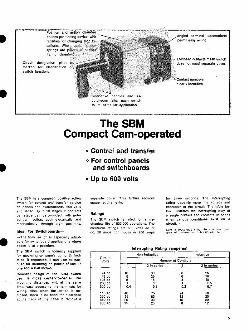
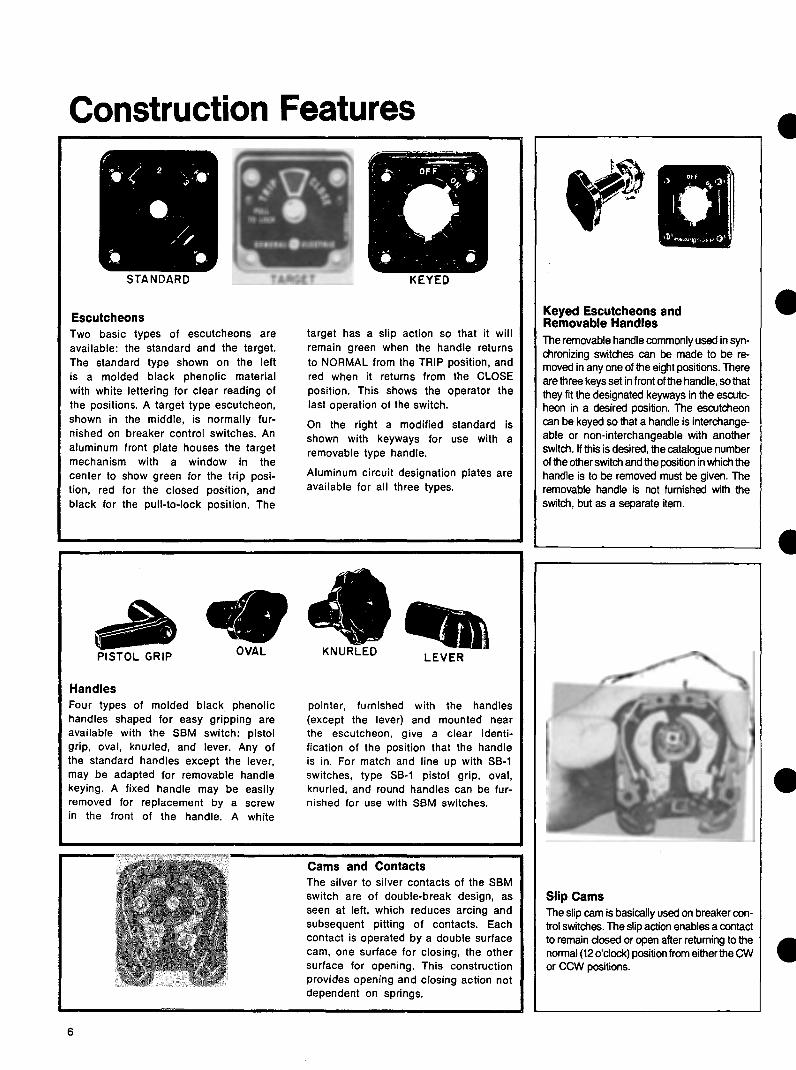
I
- Positioning Contacts of the SBM switch are positively positioned by a detent wheel mounted on a square shaft and acted upon by a springshyloaded roller arm If the shaft of the 45deg switch is not rotated more than one-half the distance between positions it will snap back to its prior position If rotated more than half the distance between positions it will snap to the next posishytion The 90deg switch has this same positive detent action when in position but the snapshyping action is not as prominent Up to eight positions are available with 45deg or 90deg between positions
-Terminal Connections Terminal connections are brought to the corners of each stage allowing screw connections to be made over a large angle This angular displacement of connection points allows the switches to be mounted on three-inch centers or less
Jumpers Jumpers are furnished assembled where required on all standard listed switches For special switches or unshylisted switches separate jumpers can be ordered-
-~ 1T)
Jumper Jumper 307V515P1 307V512P1 (Same Stage) (Adjacent
Stage)
Contacts Positions Handle End 3 2 1
1 X
o-t I-ltgt egt-11-ltgt X2
o-tl--0 X3 X
Break-Before-Make Contacts Contacts on SBM switches are normally non-overlapping (break-before-make) This sequence is illustrated above which shows that contact No 1 opens before contact No 2 closes
Another normal function is illustrated by contact No 3 which is shown closed in two adjacent positions When switching between these positions this contact will always remain closed
Spring Action Torsion springs return the switch handle to or towards the 12 oclock or No 3 position The travel of the handle is limited to 90deg to either side of posshyition 3 The switches may be furshynished with spring return both ways or only one way with maintaining action in the opposite direction You can also have spring return from posishytion No 1 (9 oclock) to position No 2 (10 oclock) andor spring return from position No 5 (3 oclock) to position No 4 (2 oclock) with maintained action in the other positions Torsion springs are housed in the rear half of the posishytioning chamber There is no need to modify the chamber to accommodate the springs
Add-A-Stage A one-half inch exentsion is provided on the rear of all switches with one to eight stages This extension enables a maximum of two adshyditional stages to be easily and economically coupled to the existing switch in the event more contacts are required Maximum number of stages including Add-A-Stage unit is 10 (20 contacts)
I I IContacts Handle End
i~IC~ cu tNrt) Oodj I xx xxxx X~inimiddot 2 XXX 3 X xx xxxx~1661 4 xx X
xx xx5 X xx~fl11bull 6X xx
Overlapping Contacts Overlapping contacts (make-before-break) contribute to the versatility of the SBM switch
Typical overlapping contacts are shown on model switch 10AA009 The asterisk () indishycates an intermediate (non-feel) position and shows the contacts overlapping In the 10AA009 when turning from the OFF position to reading position 1 (Phase 1) contact 2 doses at the intermediate position and before contact 1 which remained dosed through the intermediate position opens
Pull-To-Lock A pull-to-lock mechanism is designed for spring-return switches When the handle is turned to the 9 oclock posishytion it can be pulled out and locked in that position When the handle is pushed in the handle spring returns to the normal position This pull-to-lock feature does not actuate contacts but merely prevents the spring return of the handle
7
I Contacts numbered for easy identification
Circuit designation plate is marked for easy identification of switch functions
Good selection handles
Escutcheon plates of pershymanent-finish molded material are neat in appearance and uniform in size
Front aupport spaces body of switch ~ inch from rear of the pane allowing ample room for inaerting leads into the switch
Protective cover (not shown) completely covers all live parts meets NEMA 1 requireshyments for panel mounted switches
Type SB-1 Switch With Cover Removed
SB-1 Switch Provides Flexible Dependable Control for
Electrically-operated Equipment Type SB-1 switches are rotary camshyoperated devices for the control of electrically-operated circuit breakers small motors magnetic switches and similar devices and for the transfer of meters instruments and relays The Type SB-1 switch has molded cams assembled on a square shaft to prevent slipping Rotation of the shaft moves cams directly against contact arms so that positive high pressure results at the contact Contact action is not dependent on springs
Silver-To-Silver Contacts Silver-to-silver contacts operate with
a positive wiping action to provide lowshyresistance current flow Contacts can be removed independently of other switch parts Barriers between adjacenl conshytacts prevent arcing between circuits The switch complete with cover can be obtained with up to 16 stages two electrically separate contacts per stage and for mounting on panels from 1e to 2 thick The panel thickness should be specified when the switch is ordered if it is not the switch will be furnished for mounting on panels up to frac34t thick The SB-1 switch which has a standard insulating cover meets NEMA I requireshyments for panel mounting
Standard Parts Flexibility and low initial cost are the results of standardizing a basically -simple design Standard SB-1 switches are available for most applications For special applications switches can be built from standard parts The long~ wearing cams positive wiping action of silver-to-silver contacts and positive contact opening and closing action all contribute to a switch which is high in quality and will give you many years of dependable service
SB-1 is recognized under the component proshygram of Underwriters Laboratories Inc
I
8
I
Silver-to-siver contacts-opershy Permanent-finish molded es-ate with positive wiping action cutcheon
Contacts numbered identification
for easy Large pistol grip recommended _
handle is
Heavy-duty shunt connections can withstand millions of conshytact operations
Heavy-duty posilionfng wheel is held in place by compresshysion spring to assure positive positioning Type SB-9 Switch with Cover Removed
Removable cover (not shown) encloses all live parts
SB-9 Control Switch Designed for Highly Repetitive Service
-
-
The Type SB-9 switch for heavy-duty service is used where repetitive operashytions run into many thousands per week The SB-9 switch is similar to the SB-1 except that it has a more positive posishytioning device better insulation to ground and more substantial bearings The contact development diagrams for specific applications follow the same general form as for the SB-1
Ratings
Type SB-1 9 amp 10 switches are rated 600 volts 20 amps continuous or 250 amps for three seconds The interruptshying rating depends upon the voltage and character of the circuit and the number of contacts connected in series as
Circuit Volts 1
24 D-c 6
548 D-c
25125 D-c
75250 D-c
25600 D-c
115 A-c 40
220 A-c 25
440 A-c 12
Inductive Circuit Non-Inductive Circuit
Number of Contacts
2 in Series 4 in Series2 In Series 1 4 in Series
Interrupting Rating in Amperes
20 430 30
1540 3 2525
62511 25 2 95
7 1752 8 65
135 15 35 12545
75 24 50
12 25 4050
1225 5 20
1512 104indicated in the table Contacts can be 550 A-c 6 paralleled when current exceeds 20
Values of inductance equal to that of the average trip circuit For circuits having high values ofamps inductance refer application to your General Electric representative for recommendations
SB-1 amp 9 are recognized under the component program of Underwriters Laboratories Inc 9
Removable cover (not shown) Lateral stage contacts open Rotary stages contacts open encloses all live parts and close with push or pull of and close with rotation of
handle handle left or right
Molded escutcheon plate has durable finish and clear markshying
Type SB-1 oSwitch Without Cover
Lateral contacts give SB-10 switch increased versatility
The SB-10 Switch contacts The lateral contacts which The S8-10 switch is similar to the SB-1 provide two electrically separate and switch except for the addition of lateral mechanically independent switches in
Lateral action of SB-10 switch One Lateral Stage
Pull to open contacts 1-2 Maintaining or spring return in or out Pull to close contacts 1-2 Maintaining or spring return in or out
Two Lateral Stages Pull to open contacts 1-4 Maintaining or spring return in or out Pull to close contacts 1-4 Maintaining or spring return in or out Pull to open contacts 1-2 and close 3-4 Maintaining or spring return in or out
Three Lateral Stages Pull to open contacts 1-6 Maintaining or spring return in Pull to close contacts 1-6 Maintaining or spring return out Pull to open contacts 1-4 and close 5-6 Maintaining or spring return in Pull to open contacts 1-2 and close 3-6 Maintaining or spring return out
Four Lateral Stages middot Pull to open contacts 1-8 Maintaining or spring return in
Pull to close contacts 1-8 Maintaining or spring return out Pull to open contacts 1-6 and close 7-8 Maintaining or spring return in Pull to open contacts 1-2 and close 3-8 Maintaining or spring return out Pull to open contacts 1-4 and close 5-8 - Maintaining or spring return in or out
Pull to open denotes the same contact action as push to close Pull to close denotes the same contact action as push to open
-
one device are located at the handle end of the switch The lateral contacts operate independently of the rotary I contacts There may be as many as four stages of lateral contacts (two contacts per stage) The lateral action capabilities of SB-10 switches are given in the table The maximum number of stages including rotary contacts is 12 Lateral contacts on the same stage must open and close together There are only two lateral positions IN or OUT Contacts may be closed in either position A spring can be furshynished so that one of the positions is momentary Rotary contacts may have a spring to return the switch to neutral rotary position When a switch is furnished with both lateral and rotary spring reshy -turn the lateral spring can be loaded in the neutral rotary position only Interlocks may be provided so that the lateral action can be made in one or more rotary positions Interlocks may also be provided to prevent rotary action in the IN or OUT positions or to permit rotary action in both the IN or OUT positions The same types of fixed handles and escutcheons used on S8-1 switches may also be used with the SB-10 switches -Drilling dimensions are the same as the SB-1
silver contacts
Barriers between adjacent conshytacts prevents arcing between circuits
10
bull Special Features se-1 9 10
-
-
PositionsA The maximum number of positions is 12B Position locations and throws are availashyC ble as shownD
E F
Handles
A Round 6047044-1 B Oval 6046075-1 C Radial 6047043-1 D Knurled 6079120-1
Handles Seven different types of fixed handles are shown The handles are designed for durability comfortable grip and pleasing appearance An arrow is embedded in the oval and pistol-grip handles for visual aid in positioning A white pointer is furnished with the knurled and round handles To prevent inadvertent operation of equipshyment by unauthorized persons a removable type handle is available for the SB-1 or SB-9 switches The removable handle is keyed to fit the escutcheon in a specific position All but the radial and the lever type handles can be furnished with keyed shanks as removable type handles The handle can be removed in any one or two positions and such positions should be specified when the switch is ordered
Escutcheons The escutcheon is made of molded black phenolic material with white lettering for clear reading of position labels
G
E Large Pistol Grip 6208137-1 F Lever 6248034-1 G Pistol Grip 6046074-1 H Removable Oval
Types of escutcheons 1 The standard type C or E or F above is used when all positions are at the horishyzontal or above 2 The round type A or D above is used when there are positions below the horishyzontal
3 A target-type escutcheon B amp G above normally used on breaker control switches has a red and green target to indicate the last position to which the switch was turned Pull-to-lock target esshycutcheons are shown to the right (Note that maximum throw is 75 degrees counter-clockwise and 45 degrees clockwise)
4 Both the standard and the round type escutcheons can be furnished with keyshyways to interlock with the removable type handles so that the handle is removable only in a specific position
A separate circuit designation plate when furnished is mounted at the top of the escutcheon and is easily removable
2 POSITIONS 90deg APART bull
2 TO 4 POSITIONS 90deg APART 83
2 TO 5 POSITIONS 37 frac120 APART
2 TO 6 POSITIONS 60deg APART
2 TO 8 POSITIONS 45deg APART
2 TO 10 POSITIONS 36deg APART
2 TO 12 POSITIONS 30deg APART
Handle positions
A B
C
11
I Special Features ccoNT)
CLOSING CAM FOR ----H---t----- NO 2 CONTACT
CAM OPERATED CONTACTS
(FIG 10A)
Contacts and Jumpers Rotary contacts on SB-1 9 and 10 switches are normally break-beforeshymake Over-lapping contacts makeshybefore-break) are available and are used basically in ammeter switching applishycations Slip contact operation is availshyable for breaker control application Moving contacts are cam operated for positive opening and closing (Fig 10A) Stationary contacts are assembled on a common support mounted at the top of the switch for easy replacement Three types of stationary contacts are availshyable (Fig 10B)
A Electrlcally common with center binding post which affords single-break single-pole double-throw operation for two electrically common circuits
B Electrically separate Each stage affords single-break single-pole service for two electrically separate circuits
C Electrically common without a center binding post affording two contacts for double-break action Greater switch flexibility can be achieved by use of jumpers (Fig 10C) Four difshyferent types are illustrated When jumpers are ordered with the switch they are supplied unassembled without additional cost They may also be purshychased separately and assembled on existing switches
Spring Return Action
3
Spring return can be adapted to any SB-1 9 and 10 switch providing these limitations are adhered to 1 The handle must return to or toward the 12 oclock position but not pass it 2 The maximum throw is 90deg to either side of the 12 oclock position 3 You cannot have a maintained posishytion pas a spring return position Example if spring return from pos 2 to pos 3 is desired pos 1 cannot be a maintained position However the funcshytional equivalent can be obtained by specifying a pull-to-lock action in place of the maintained position Spring return from both directions to NORMAL or spring return with mainshytained action can be provided on the same switch Example A Spring return from position 1 and 2 to 3 maintaining in positions 3 4 and 5 or spring return from 5 to 4 to 3 maintaining in positions 1 2 and 3
A
B o---U---o o---U--o
C o-lHt--o
(FIG 10B)
atgt flt ~ (SAME STAGE) (ALTERNATE STAGE) 307V512PI 6244177PI
ff Qnnu() 6149141 Pl 1455504PI (ADJACENT STAGE) (FLEXIBLE)
(FIG 10C)
IB A five position switch can be furshynished with partial spring return from positions 1 to 2 and or 5 to 4 with maintaining action in the remaining positions SB-9 only)
Pull-To-Lock A pull-to-lock may be added to lock the switch against spring return action Lockshying is accomplished by pulling the handle out in the pull-to-lock position to engage a latch which arrests the spring return The switch will remain in the locked posshyition until the handle is pushed in Note This pull-to-lock feature does not actuate contacts when pulled
The following are standard pull-to-lock combinations available with a standard target type escutcheon -A Spring return from all positions to NORMAL except when middot locked pull handle to lock at 75deg CCW
B Spring return from 45deg CW and CCW to NORMAL pull to initiate locking at 45deg CCW then turn to 75deg CCW and pull-to-lock
C Spring return from 45deg CW and CCW except when pulled-to-lock at 45deg CCW Special pull-to-lock switches can be I furnished however spring return action from the pull-to-lock position is reshyquired
12
Optional Features se-1 9 10
PullTo-Turn A pull-to-turn feature can be incorporatshyed in a SB-1 or SB-9 switch to prevent accidental operation The handle is locked against turning when it is in the in position and must be pulled out to unlock and turn to the selected positions it is equipped with a lateral spring that pulls the handle to the in position
The handle can be locked against turning in one or more positions or can be free to rotate between certain positions while in the in QOsition
Locks Two different types of locks are availshyable Each allows the switch to be locked in one or more positions One lock is built into the operating handle The other lock is separately mounted on the panel above the switch and when necessary can be coordinated with a Kirk key-interlock scheme When it is necessary to lock switches in more than one position a 45-degree space must be provided between adjashycent locking positions Therefore eight is the maximum number of lock posishytions that can be furnished
Rotary spring action is not recommended with pull-to-turn because the lateral spring may not always overcome the roshytary spring and automatic return to neushytral may not always occur
Push-To-Turn The push-to-turn feature is almost the exact opposite of the above-shown pullshyto-turn feature and the same restriction as to the use of rotary spring return applies
Palladium Cltgtntacts Available for temperature meter switches Palladium contacts have a constant resistance factor which is necessary because calibrated leads are normally used in temperature meter cirshycuits Silver contacts would result in a variable resistance factor and cause fluctuations in meter readings
13
Hand And Electrically Operated Switch Type SBE
~middot-
DESCRIPTION The SBE switch is basically a hand or electrically operarted SB-1 switch The electrical operation is acshycomplished by the use of a high-torshyque vdc motor regulated by the use of an electronic controller and atshytached to the switch by a clutch mechanism
The SB-1 switch portion consists of up to twelve customer-usable silver to silver cam operated contacts with a positive high pressure self-wiping action See Figure 2 for typical conshytact arrangement
The SBE is available for mounting on panels 1 16 to 1 8 thick
APPLICATION SBE switches can be used in place of
the manual-only circuit breaker control switches which can allow remote SCADA supervisory control Even though the SBE switch is longer than the standard SB-1 breaker control switch the panel space for either device is the same Therefore retrofitting manual-only locations with reshymote control is relatively easy
A typical contact wiring diagram is shown in Figure 2 Additional contacts can be used with a white indicating light or alarm to indicate a protective (not operator) trip Also provided are contact to be used with an automatic recloser interlock circuit
This same switch may also be used with different position engraving for opshyeration of motor-operated disconnect switches small motor contactors and similar bi-directional devices The applishycation should be checked for operation with a contact dwell time of 1 second in each direction (CW and CCW) when the SBE is operated electrically
BREAKER CONTROL
D$- middotmiddotmiddot- lto
i middot r-
~ ---
CONTACTS POSITIONS HANDLE
END CLOSE NORMAL AflER CLOSE
NORMAL AFHR TRIP
TRIP
1 2 1 X o--tHI--() 2 X
3 4 3 X X OmiddotH-0 o-H-o 4 X
5 6 5 X X o--l 1-o o--l 1-o 6 X X
Fig 1 SBE switch with cover removed
BURDENS For 125 VDC Motor at 150 VDC
bull 1 amp for 200 ms bull 07 amps for the second dwell period
RATINGS Operating Range of 125 VDC Motor Fig 2 SBE switch
bull 785 to 150 vdc Contact Arrangement
CONTACT RATING -NON-INDUCTIVE CIRCUIT INDUCTIVE CIRCUIT NUMBER OF CONTACTS NUMBER OF CONTACTSCIRCUIT
VOLTS 42 4 2 11 INININ IN
SERIES SERIESSERIES SERIES
300 48 DC
40 20030024 DC 60 250
125 DC 400 30 150025050
95 250 DC
250 20 62511026 65
600 DC 80 07 17520075
125015 035135025 045
500 220 AC
2405004000115 AC 500 2502500 120 400
440 AC 2501200 200 550 AC
50 120 120 15 0600 40 100
The interrupting ratings of the conshy The contacts will carry 20 amps conshytacts vary with the inductance of the cirshy tinuously or 50 amps for 1 minute The cuit The values given above for de inshy contacts will close on 50 amps for volshyductivemiddot circuits are based on the avershy tages 600 volts or less age trip coil currents
14
I
I
(i) ---~--------------r---------------r--------125VOC
CLOSE TRIP 52CS(CW) (CCW)tl_ 52CS C
~ NAC NAT rcsTB Tl3 I 0 TB6
52CSJ_ 52CS 522E0 CIRCUJTC NAC CLOSE CJRCUITS
TBS52 b
PROTECTJVE TRIP ALARM
ANO OR INDICATING
LIGHT
52 a
~ 5CS 52 ~CNAC TC
AUTO RECLDSER INTLK
Fig 3 Typical Control Circuit with SBE (286A3555)
(-) ___j____________j______________________125VOC
15
The operating cam of SB-1 -9 and Cam Action and Limitations -10 switches is based on a 30-degree cut to each side of the center (Fig 1 ) A standard-profile cam will fully open or close a contact in 30 degrees making or breaking 15 degrees from
Fig 1 Operating cam for SB-1 -9 and -10 switches
NO I CONTACT r==== a OR
COMMON OPENING CAM
coR CLOSINGFRONT VIEW HANDLE CAM FOR NQIIN 12OdegCLOCK POSITION CONTACT NOT SHOWN
Fig 2 Composite view of contacts and cams
C B
Fig 3 Individual arrangements of cams in Fig 2
( BACK)POSITIONCONTACTS VIEW HANDLE END
3 2 I
1 I Xo-u--0-11--0 I 2 X X
Fig 4 Contact arrangement back view
the fully open or fully closed position Fig 2 is a composite view of I
contacts and cams assembled on a stage of a switch This figure shows that odd-numbered contacts are on the right side of the switch (viewed from the front) and are closed by the C cam Even-numbered contacts are on the left side and are closed by action of the A cam Both contacts are opened by the B cam
Fig 4 is the contact diagram for Fig 2 with Fig 3 showing the individual arrangement of cams
0 n e cam limitation must be -considered when the switch rotates 180 degrees or more Referring to Fig 3 you see that when cam B is rotated 180 degrees the same relationship occurs between the periphery of Cam B and the contact mechanism of Conshytact No 1 as occurred between the periphery and contact mechanism of Contact No 2 before rotation thereshyfore whatever happens to one contact at any point in the switch rotation must happen to its companion contact in the same stage when the switch is rotated 180 degrees Fig 5 shows the diagram of an unworkable and a I correct arrangement
When contacts on the same stage cannot be arranged to avoid this 180-degree cam limitation one contact per stage is used (See Fig 6) On five-position switches 37-1 2 degrees can be used instead of 45 degrees to avoid this limitation
SLIP CAMS Slip cams increase the flexibility of
the switch They allow a contact to be closed in the NORMAL position after returning from either the CW or CCW position and also to be open in the NORMAL position after returning from the opposite direction This -action is accomplished by allowing the cam to slip 45 degrees as shown in Fig 7 Once the shaft actuates the cam the shaft wil I then slip 45 degrees in the opposite direction without actuating the cam
This type of action is commonly used for circuit-breaker control applishycations Fig 8 shows a breaker conshytrol switch Model 16S8182 which has slip action on Contacts 7 and 8 With this slip action there are some -limitations Three of these limitations and how to avoid them are shown Limitation No 1 does not apply to the SBM switch because of the indepenshydent cams for each contact
16
I
Cam Action and Limitations (Contd) INCORRECT CORRECT
POSITIONS (BACK VIEW) POSITIONS (BACK VIEW) ICONTACTSCONTACTS HANDLE END HANDLE END8 7 6 5 4 2 I3 8 7 5 4 3 2 I6
I 2 o-H-0 0-11--0
3 4 o-n-o o-11--0 5 6ltgtbullHo o-H-o 7 8 o~ o-H-o
Fig 7 Diagram showing
( I NCORRECTl
2 2N IN I
I 2 11 XX o-H--o o-H-o I 2 X X- (CORRECT)
2N IN I2
I I X X o-j l--0----
4
1-ltgt--lkgt 4 X X
Limitation No 1 (SB-1 -9 amp -10)
A slip contact and standard-
I
2
3
4
5
6
7
8 X X
X X
X
Fig 5
I
7
SLIP
STANDARD
X X
5
ESCUTCHEON ( FRONT VIEW)
X
Diagram
3
4
I 2 o-O-o o1-o 3 4 o-H-o o-H-o 5 6o-H-0 o1-o 7 8 o-11-o ~l-0
I
2
3
4
5 6
7 8 X
X
X
X
X
X
X
X
of unworkable and correct arrangement
POSITIONS (BACK VIEW CONTACTS HANDLE END 8 7
ol--0--I
~k)
~l-o-1
1-o-11-0
I
4 X X 5X
8
6 5 4
X
X
X X
3
X
X Fig 6 Contact arrangement to meet cam limitations
CONTACTS HANDLE END
I 2 0-11-0 rH-o
1~4o-1 ~ 5 o-r- __1ry
I~ ao-1 o-j~
I
2 3
4
5
7
8
45-degree slip action of cam Fig 8 Breaker control switch model 16SB182
( INCORRECT l
3 3N
I 2 11 ~1--o o-U-o 12
(CORRECT)
I 2 I )gt-i l-0 0- 2
3~ f--0 0- 4 ) 4
3 3N
X X
2N
X X
2N
X X X X
2
X X
2
X X X X
I
I
X X
2 I
X
X
37
4 5
ESCUTCHEON (FRONT VIEW)
POSITIONS
Close
X
X X
X X
Norm Norm ofter ofter Trip close trip
X X
X X
X X
( INCORRECT)
2
I 2 I I o-n--o o f--0 I2
( CORRECT)
2
I 2 )(jgtmiddotH--0 0
~ 4_I f--0 o-f gt
I 2
3
4
2N
2N
X X
IN
X X
IN
X X X X
I
i X X
Limitation No 2 ( SBMS81 -9 amp -10)
contact On a 4-position pull-to-lock switch tht A contact cannot be closed in the
Limitation No 3 (SBM SB--1 -9 amp -10)
cannot be on the same stage as shown in slip contact cannot be closed in the 2N and normal after position without also closing in the top diagram 2 positions (As shown in the top diagram) the position itself as shown in the top
A stage must be added and contacts split without closing in position 1 To accomplish diagram To accomplish this a stage must be up as shown in the bottom diagram one this a stage is added and the contacts are added and the contacts set up as shown in contact per stage (Does not apply to SBM) connect in series as shown in the bottom the bottom diagram with the contacts
diagram placed in series by jumpers Jumpers required are shipped loose with the switch
17
Overlapping Contacts mediate position is identified by an degrees between positions by use of aGENERAL X in the block above this position in special cam
Contacts on Type SB switches are the operating requirement table ConshySB-1 -9 AND -10 SWITCHESnormally non-overlapping (breakshy tacts 1 and 2 are shown overlapping in
before-make) This sequence is the intermediate Positions 4 and 6 illustrated in Fig 10 which shows that Contact 2 is shown making in intershyContact No 1 opens before Contact mediate Position 4 before Contact 1 No 2 closes when turning from breaks when going from Position 3 Position 1 to Position 2 Another (OFF) to Position 5 (PHASE 1 ) and normal function is illustrated by Contact 1 will make before Contact 2 Contact No 3 which is shown closed breaks when going from Position 5 to in two adjacent positions (Positions 2 Position 7 and 3) When switching between these Figure 12 illustrates an ammeter positions the contact will always switch for three independent current remain closed There are some circuits transformers (similar to Model where this action is not desired such 10AA013) This switch also has overshyas switching current transformers to an lapping contacts and intermediates at ammeter Here the contacts must Positions 2 4 6 and 8 however the overlap (make-before-break) to overlapping action takes place between prevent damaging the meter the intermediate position and the
actual position The X on the lineSBM SWITCH between the positions of thl contacts
To get this overlapping action on identifies this action When turning the contacts 90 degrees between from Position 5 (PHASE I) to Position pos1t1ons is required Figure 11 7 (PHASE 11)Contact 1 makes before illustrates an ammeter switch (similar Contacts 2 and 3 break Also Contact to Model 10AA009) with overlapping 2 and 3 break before Contacts 4 and 5 contacts The overlapping action takes make and Contacts 4 and 5 make place in the intermediate positions before Contact 6 breaks All this (Positions 2 4 6 and 8) The inter- action takes place within the 90
Fg 10 Typical non-overlappingPOSITIONS HANDLE END CONTACTS
(break-before-make) sequence 3 2 I I 2 I Xo-H-o o-H-o 2 X
3 X X~1--o AMMETER
OFF
INTER POSITION
~ 7 IJltI 5 1( 3 I
3
2
AMMETER CONTACTS POSITIONS OFF ODD EVEN 8 7 6 5 4 3 2 I
3 o-U-o o-H--o I
2 X X rx ~ X X -~-
(V 1
2 o-U--ltgt ltgt41--o
3 4 oc
kX
o-11--o ltgt41--o 5 6 x
)( ~
Kx Iv
o-0--o ltgt41--o 7
8 X gtL00 -
~-
o-11--o o-H-o 9 ex
Basically the overlapping action is the same as with the SBM switch but Iit is not limited to positions which are 90-degrees apart
To get a make-before-break action as shown in Fig 13 a minimum of 37frac12 degrees between positions is required To get a make-before-break as shown in Fig 14 a minimum of 60 degrees is required The flexibility of the SB-1 -9 and -10 switch allows the comshybination of 37frac12 degrees and 60 deshygrees in the same switch to give you an ammeter switch which reads as many as six independent current transshy -formers with either 1 or 2 0 F Fs (see Fig 15)
A special contact sequence which requires a contact to close in adjacent positions but to open momentarily between them is shown by Contact 1 in Figure 16 A minimum of 60 degrees between positions is required When less than 60 degrees is required use two contacts in parallel as shown in Fig 17
I INTER POSITION
7531 POSITIONS
ODD EVEN CONTACTS
4 3 2 I
I
8 7 6 5 X XX XX X Xo-11--0 o-H-o 2 XX X
3X XX X XX Xo-H--o o-t f-o 4X XX
sx X X X XX Xo-11--o ltgt41-o 6 X XX
Fig 11 Overlapping contacts for SBM ammeter-type switch connected at end of secondary -
Fig 12 Overlapping contacts for AMMETER POSITIONSCONTACTS SBM ammeter-type switch with three HANDLE ENO Inter Inter I3 22 3 independent circuits I X IX
2 X XX Xt~~ 3 XXH~ 4 X XX X
Fig 13 Overlapping contacts for SB-1 ammeter-type switch 18 connected at end of secondary (two current transformers)
2
Overlapping Contacts (Contd)
AMMETER CONTACTS HANDLE END
3 ~hgt--4~
~1--o
~~~ ~~
~hgt--4~
~rltgt
CONTACTS HANDLE END
6 2 I o-H-~
5 3 4
3~ 40- 1-o
51~ 6o-j rltgt
7 ~ 8 ~ I-ltgt
I
2
3
5
6 7
9 10
II
I
3 4
5
6 7 8
3
X
X
X X
6 5
4
6 X
X
POSITIONS
X X
XX
X X X
X
X
X X X
X
AMMETER OFF
I 2
3
2
X
X X
X
X
X X X
X
XX X X
X X
XX
I
X X
X
X
CONTACTS HANDLE END
POSITIONS
5 X
X
4
X
X
3 X
X
2 X
X
Fig 14 Overlapping contacts for SB-1 ammeter-type switch with three independent circuits
I X
X
Fig 15 Overlapping contacts for SB-1 ammeter-type switch with six independent circuits
POSITIONS - BACK VIEW u
u 0
Fig 16 Special contact sequence which requires one contact to be closed in every handle position but to open momentarily when switching
Fig 17 Special contact sequence POSITION - BKVIEWCONTACTSwhich requires one contact to be
HANDLE END 876543218 2closed in every handle position but to IX XX X7 3open momentarily when switching 2X XX Xhowever when less than 60 degrees 6 4
5 X X X Xbetween positions is required two ~ontacts are connected in parallel X X X
19
To prevent operation ofequipment by unauthorized persons switches with removable handles are available The handle is keyed to a specific escutcheon to be inserted and reshymoved in a designated pos1t1on Handles can also be mutually keyed to other escutcheons so that they are either interchangeable or non-intershychangeable with other switches
This feature is available for SBM SB-1 and SB-9 switches but ordering procedures differ
SBM SWITCHES
0 3 0
5I 0 6 0 7 0
Fig 18 SBM switch keyed escutchshyeon with eight available keyway locashytions Keyways 1-3-5 are shown
The keyed escutcheon on the SBM switch ( Fig 18) has eight possible keyway locations Three are normally used and are assigned by the factory The choice is influenced by several factors
a If the handle is to be intershychangeable with that of another switch the position in which each handle is to be removeable must be considered
b If the handle is to be non-intershychangeable the keyways assigned to other removeable handles in the same panel must be considered
c If no special instruction is given by the customer when he orders the factory will assign keyways at random if more than one SBM switch has a removable handle they will be keyed to be non-interchangeable
A removable handle is furnished as a separate item not with the switch it operates because in some cases the single handle operates many switches The handle is keyed so that it will fit through the keyways on the escutcheon in a specific position
When ordering a removable handle specify the type the position in which it is to be removable and the switch or switches it will be used with The factory will assign the handle To
Removable Handles TABLE 1 Nomenclature guide for SBM removable handles
1st 2nd 5th Number 1st 2nd 3rd 4th
Letter LetterNumber NoNo No
Action ofRemovable Common Escutcheon Type Handle
Rotation Keywaysin Position Code
W=CWampCCW 11 = Knurled 1 w 1 1
L = CCW (special) thru thru thru2 = Oval thru
R = CW (special) 8 grip
3 = Pistol 8 88
Example 1 21WW135
This oval handle has keys at positioos which when it is in position 1 or nine oclock will line up with escutcheon keyways 1 3 and 5 It is therefore removable in position 1
identify SBM removable handles see Table 1
SB-1 amp SB-9 SWITCH
The keyed escutcheon for the SB-1 amp
SB-9 switch is normally furnished with two keys and three keyways (see Fig 19) The circumferential location of the keys and keyways will vary depending on the location etc in which the handle is to be removable The location of the keyways is assigned by the factory
Table 2 gives a list of standard keyed escutcheons and the proper removable handle for removing the handle in both the vertical ( 12 oclock) position and 90deg ccw (9 oclock) pos1t1on Escutcheons 6016164P-2 thru P-14 are used on switches if the throw does not exceed 90deg on either side of the vertical ( 12 oclock) position and P-23 24 and 25 are used when the throw does exceed this limit
0
Fig 19 SB-1 escutcheon for use with removable handle
-
-Oval handles 16S81CC1 thru 32 are
listed with direction and degree of throw from the positions in which they are removable The code letters A thru Z in the left hand column identify the escutcheons used on the basic unlisted switches
I Example 16S81AB300S~M3Y the 2nd form letter ~ identifies a keyed escutcheon 6016164P 3
When a special keyed escutcheon is required different from any of those listed the code letter X is used followed by the part number
Example 16S81AB300SX34M2Y
All keyed escutcheons will now have the part number stamped at the bottom left hand corner instead of the code letters previously stamped at the bottom righthand corner If the code letter or other indentification is deshy -sired it will be stamped at the bottom righthand corner by requisition only (three characters maximum) The 16S81CC oval type removable handle will now have the form number only stamped on the lower face of the handle Those removable handles which have metal shanks (6119745G) will have the group number stamped on the shank When a switch with a Ikeyed escutcheon for a removable handle is ordered be sure to specify the position in which the handle is to be removable If an existing handle will be used give the number of the existing handle
20
Removable Handles (Contd)
I TABLE 2
Model Number
Code Escutcheonbull Handle Throw
Handle Removable in Vertical Position
I
A 6016164P3 16S81CC1 A 3 CC18
B 4 CC2 4 CC19
C
B
5 CC3 5 CC15
D
C
6 CC4 D 6 CC11 D 6 CC22 D 6 CC27
E 7 CC5 7 CC12E
E 7 CC13 7E C20 7E CC25
F 8 CC6 F -8 CC14 F CC248
CC7G 9 G 9 CC8
CC17G 9 G 9 CC26 G 9 CC29
9 CC21
H
G
10 CC23 H 10 CC9 H 10 CC10
10H CC31 10H CC32
J 23 CC18
y 24 CC19
z 25 CC21
Handle Removable 90deg CCW
K 6016164P11 16S81CC1 K 11 CC18
L 12 CC2 12L CC15
M 13 CC3 13M CC15
N 14 CC11 N 14 CC27
14N CC4 14N CC22
SpecialX
135deg cw 360deg
135deg cw 360deg
135degCW 360deg
135deg cw 45degCW amp ccw 45degCCW 360deg
45 cw 75degCW 45degCWamp ccw 360deg 75degCCW
45degCW 45degcw amp ccw 36QO
Type SB-1 and SB-945deg CW I Eng 45deg CCW R Eng 45degccw 135deg CCW 45degCW 360deg OFF
360deg 45deg CW I Eng 45deg CCW R Eng
1
)j~bullbullo+ 45degCW 45deg ccw
I 360deg
360deg
360deg
135degCW 360deg
135degCW 360deg
135deg cw 360deg
45degCW amp ccw 360deg 135deg cw 45degCCW
The P number (3 4 etc) is used as the part Fig 20 Typical removable handles number in the text and escutcheons
21
I
Temperature-Meter Switches
Temperature-meter switches are Fig 21 shows a temperature-meter circuit with a TEST and an OFF furnished with palladium contacts switch Model 16SB 1 CE52 reading position On a three-wire circuit you which have a constant resistance factor This is necessary because calibrated leads are normally used in a temperature-meter circuit and silver contacts would result in a variable resistance factor and cause fluctuation in meter readings
TEST METER Off ~
~ jQr
Ii-2
four RTDs on a two-wire circuit with a TEST and an OFF position On a two-wire circuit you can transfer up to seven coils with an OFF position or six coils with a TEST and an OFF position
Fig 22 shows a Model 16SB1CE55 reading three RTDs
TEMPERATURE METER TRANSFER SWITCH
TRANSFERS TWO WI RES TO FOUR COILS WITH TEST a OFF
MODEL NO 16SBICE52
POSITIONSCONTACTS HANDLE END GI Ill =-C
I-4 i ICs co~ 2~ -
I I X o~ ~~ 2 X
43 3 X XX l-0~ r - 4 X X X
55 Xo-H-~ 6
6-- 1-o X 7 X X X1~LJ 8l-0o-1 r 8 X X X
~ 9 XI 109 II - 1-o 10 X II X X XI 12II
o-i - ~ 12 X XX 115 V A-C SOURCE
X y
FUSES
TEST RESISTOR
C B
4 3 2 DETECTOR COILS IN MACHINE
Fig 21 Temperature meter switch Model 16S81CE52
on a three-wire
TEST METER Off ~
~
can transfer up to six coils with an OFF position or five coils with a TEST and an OFF position When it is required to transfer more RTDs than the maximum for a given switch two switches with a removable handle may be used
TEMPERATURE METER TRANSFER SWITCH
TRANSFERS THREE WIRES TO THREE COILS WITH TEST 8 OFF
MODEL NO 16SBICE55
POSITIONSCONTACTS - 3
- Ill
pound CU
0HANDLE ENO - iC 2 c cl C Ci i I 2 I X 0-1-0-11-0 2 X 3 4 3 X X X 0-l-0-if-0 4 X XX 5 6 5 XX X ltgt-it-o-lrO 6 XX X 7 8 7 Xo-H-ltgt-Hmiddoto 8 X 9 10 9 X XX o-l~r-6 10 X X X II 12 II XX Xo-lkgt-1~ 12 X XX
115 V A-C SOURCE X y
FUSES
TEST RESISTOR
C
3 2 I DETECTOR COILS IN MACHINE
Fig 22 Temperature meter switch Model 16S81CE55
I
22
Outline Dimensions Type SBM Control and Transfer Switches
Hgndi11
li7bull
1-8
Standard ____ Oval SwitchNoof
Stages A B
gbull2
16 1 31 21e 2 4frac12 2v 3 51e 21e
4 51 2v 5 6frac34 2v 6 7 21a
7 7 2v 8 8frac14 21 9 8frac12 2v
10 91a 2v
Knurled
f28
Lever
SHIPPING WEIGHTS
When panel is 1bullthick -add l2to A and B dimensions
Pull-to-Lock Removable Switch Handle Switch
A B A BI I
4) 211 4frac34 3) SJ 27e 5o 3) 5frac34 21a 6 3)
6 271 65a 3) 7) 21 7frac14 3) 7frac126 21o 77e 3)
8) 211 8frac12 3) 8) 21o 91 3) 8frac34 211 91 9) 9 211 9frac34 3)
Approx weights are listed below All weights listed apply to SB switches consisting of one stage Add 6 ounces for each additional stage
Type SBM (1 Stage) 1frac12 lb
(This data is subject to change without notice)
23
---- --- --- --- ---
Outline Dimensions ccoNTgt
Type SB-1 Control and Transfer Switches
(For estimating only) Panel
311
~lt-- Handles 1321--t 1 f-- frac12 drill (3 holes)
T ~~cutcheonmiddotf -~-middot- l--r11
3_] aI 132
-A-_j - 8 -- To1
I Oval I
I I
I I
No of
Stages
Radial
Round 12-8
Ti 1 514 2s 6
7
B
9
10
11
12
13 Locked
14handle
4 15
16
remove cover
SB-1 switch with fixed handles (Outline 116A 130)
Dimension in Inches
Standard Cover
Standard Cover 12 Wires Out Top
and 24 Wires Out Bottom
A I B
5 1316 10116
11 16 20 156
11 136 22 716
13 frac126 25 76
14 1316 28 76
I C
4 frac12
Lorge Cover
Large Cover 24 Wires Out Top
and Bottom
6 116 10 116
4 1116
10 916 19 1116
11frac126 21 316
For spring-return switches when more than three and less than seven contacts close in the normal handle position add frac34 to A and 1frac12 to B When seven or more contacts close in the normal handle position add 1frac12 to A and 3 to B
Note Removable handles are similar to fixed handles and availshyable in all styles except radial and locked They do not alter switch dimensions or panel drilling
SHIPPING WEIGHTS Approx weights are listed below All weights listed apply to SB-1 switches consisting of one stage Add 6 ounces for each additional stage
Type SB-1 (1 Stage) 2 lb (This data is subject to change without notice)
I
I
24
-----
-----
----------
-----
-----
------
-----
---------
---------
---
---
------
---
---
---
---
---
------
------
---
---
---
---
---------------------
---
I
-
No of Stages
I 1
2
3
4
5
6
7
8
9
10
11
12
13
14
15
16-
Outline Dimensions ccoNT)
Type SB-9 Control and Transfer Switches
(For estimating only)
Panel-mounted Type SB-9 switch (Outline 116A139)
PANEL-MOUNTED TYPE SB-9 Dimension ir Inches
Standard Cover 12 Wires out Top and 24 Wires out Bottom
A 8 CI I
41a
51a
61a
71 -~--
71
81a
91a
101a
101e
111a
121a
131a
131e
141a
151o
161
83a
91a
111a
121
141
151e
171
181a
201a
middot211a
231a
241e
261
271e
291a
301e
4frac12
Lorge Cover 24 Wires out
Top and Bottom
A 8 CI I
51a
51
61a
71
81a
81a
91a
10
111a
111e
121a
131a
141a
141e
151a
16 lo
8frac14
101
111a
131a
14frac14
161
17frac14
191a 4l5Ji6
201a
221a
23frac14
251
261a
281a
291a
311a
For spring-return switches when more than three and less than seven contacts close in the normal handle position add frac34 to A and 1frac12 to B When seven or more contacts close in the normal handle position add 1frac12 to A and 3 to B
Note Removable handles are similar to fixed handles and availshyable in all styles except radial and locked They do not alter switch dimensions or panel drilling
SHIPPING WEIGHTS Approx weights are listed below All weights listed apply to SB-9
- switches consisting of one stage Add 6 ounces for each additional stage
Type SB-9 (1 Stage) 3 lb
25
-----
------
----------------
I Outline Dimensions ccoNT)
Type SB-10 Control and Transfer Switches
(For estimating only)
Panel
bull ICx2 16 wide
11or8
n3
-----A----- Panel Ori I ling ---B to Remove Cover (front view)
No of Stoges
1
2t
3t
4t
5
6
7
8
9
10
11
12
Panel-mounted Type SBmiddot10 switch
Dimension in Inches
Standard Cover Large Cover
A B C A B CI I I I I 6frac34
6frac34
7frac12
8frac14
9
9frac34
10frac12
11frac14
12
12frac34
13frac12
Ufrac14
12frac12
12frac12
14
15frac12
17
18frac12
20
21frac12
23
24frac12
26
27frac12
4frac12
12frac347
7 12frac34
7frac34 14frac14
8frac12 15frac34
9frac14 17frac14
10 18frac34 4 15i6
10frac34 20frac14
11frac12 21frac34
12frac14 23frac14
13 24frac34
13frac34 26frac14
14frac12 27frac34
bull Includes both lateral and rotary stages
(Outline 0l65A6122)
SHIPPING WEIGHTS Approx weights are listed below All weights listed apply to Type SB-10 switches consisting of one stage Add 6 ounces for each additional stage
Type SB-10 (1 Stage) 3frac12 lb
(This data is subject to change without notice)
I
I 26
I
-
- ADD 14 TO A amp B DIM
FOR LARGE COVER
NOOF STAGES A B
1 5-116 7-7 16
2 5-1316 8-1516
3 6-916 10-716 - 4 7-516 11-1516
5 8-1 16 13-716
6 8-1316 14-1516
7 9-916 16-716
8 10-516 17-1516
9 11-1 16 19-716
10 11-1316 20-1516
11 12-916 22-716
12 13-516 23-1516
13 14-116 25-716
14 14-1316 26-1516- 15 15-916 28-716
Tandem Switch Outlines
PANEL
frac121 il 11 F--~--F-----F ----A~
B TO REMOVEOUTLINE COVER
NOTE ALL DIMENSIONS ARE IN INCHES
i---------c-------i PANEL
TWO SWITCH TANDEM SB-1
Gear-operated (360deg rotation)
THREE SWITCH TANDEM SB-1
Gear-operated (360deg rotation)
FOUR SWITCH TANDEM SB-1
Gear-operated (360deg rotation)
DRILLING -
C
7-12
11
14-1 2
D
2
5-12
5-1 2
FRONT
E
8-14
11-34
15-1 4
VIEW
F G
3-1 2
a w gta3-12 0w ugt w0 ()u aI ltI Ilt a~
() 0 ua
03-1 2 u ~
N
(This data is subject to change without notice)16 16-516 29-1516
Fig 23 Tandem-switch outline 27
Outline Dimensions for Locked Handle Switches
3116 DI A--- + -r--------
~ 1gttl~1
f DIA--1-4-----fyen-l 3
t 32-rDIA(3l___ PANEL DRILLING (FRONT VIEW)
l middotcbullx2 1
16
WIDE
t~omiddot--1 32 FOR frac14-ifrac14 PANEL
~ FOR I a 2 PANEL
~ FOR 1-t PA~~~-----~
~18
11 TO REMOVE COVER
SB-switch with Yale Lock above the switch ForA and B use standard dimensions plus D depending on panel thickness
SB-9 SWITCHES
STANDARD DIMENSIONS IN INCHES
STANDARD COVER 12 WIRES OUT TOP LARGE COVER
NOOF AND 24WIRES 24WIRES OUT STAGES OUT BOTTOM TOP AND BOTTOM
A B C A B C
1 4-78 8-38 5middot18 8-58
2 5-58 9middot78 5middot78 10middot18
3 6-38 11-38 6-58 11-58
4 7-18 12-78 7middot38 13middot18
5 7-78 14-38 8-18 14-58
6 8-38 15-78 8middot78 16middot1 8
7 9-38 17-38 9-58 17-58
8 10-1 8 18-78 10-38 19middot1 8 4 12 4 15169 10-78 20-38 11-18 20-58
10 11-58 21-78 11-78 22-18
11 12-38 22-38 12-58 23-58
12 13-1 8 24middot78 13middot38 25-1 8
13 13-78 26-38 14middot1 8 2amp58
14 14-58 27-78 14-78 28-1 8
15 15-38 29-38 15middot58 29-58-16 16-18 30middot78 16middot38 31-18
(This data is subject to change without notice)
28 Fig 24 Dimensions control switches with Yale or Kirk Lock
I
Contact Diagrams for SBM Switch
-I VOLTMETER Source Voltmeter
POSITIONS Fig 25 VOLTMETER SWITCH OFF
0-idouble-pole single-throw ON OFF0Model No IOAAOOI 2X
XKnurled handle
VoltmeterVOLTMETER ~ONTACTI POSITIONSHANDLE - OFF ENDFig 26 VOLTMETER SWITCH ltgt I-
0 double-pole double-throw
2 l5 I ~cModel No 10AA002 2
ltgtl~fo I X 2 XKnurled handle
3 43 Xltgtl~fo14 X
VOLTMETER ONTACTI POSITIONSFig 27 VOLTMETER TRANSFER HANDLE N 3 2 I2 ENDSWITCH three-phase
J -transfers lour wires -shy 8Jffic 3 2 lo- 0
I phase-to-neutral 0 IXltgt1tpifo I XModel No 10AA003
3 Xltgtl~ltgtifoKnurled handle 14 IY IX
VOLTMETER tONTACT5 HANDLEFig 28 VOLTMETER SWITCH
END1 2-3
JPhase-to-phase or _ N-cjffi-phase-to-neutral l)N - Move this-08 c0- jumper0 I X IXModeNo 10AA004 3-phose 3-wirP to 1-2 whenrot xx
connectingKnurled handle 3 X switch 3 ltjgt4w~~ 4 X 3-phose 4-wire (future
alternate connection)
Ivo mete I VOLTMETER ~ONTACTI
HANDLE 4 3 2 I 2 END I ~o 2 6I J u
ucJffiFig 29 VOLTMETER SWITCH 8 c 2 I 04 3OFF 0 4 I- n 4 3Xfour circuits two wires Iltgtl~fo~ XModel No 10AA005 IIX - 5 dltgtI~- 4 -
IX I f6Knurled handle X Iltgtiffdeglo ~ h7 8X IX7ltgti~lo 8 X
x in all contact diagrams denotes contacts closed
29
Contact Diagrams for SBM Switch
DESCRIPTION
VOLTMETER TRANSFER
SWITCH three-phase transshy
fers four wires phase-to-phase
and phase-to-neutral
Model No I 0AA006
Knurled handle
Fig 30
Fig 31 VOLTMETER SWITCH two
three-phase three-wire
circuits Model No 10AA007
Knurled handle
Fig 32 AMMETER TRANSFER SWITCH
three CTs (connect at
end of secondary I
Model No I 0AA00B
Knurled handle
Fig 33 AMMETER TRANSFER SWITCH
three Cls with off
connect at end of secondary)
Model No 10AA009
Knurled handle
Fig 34 AMMETER TRANSFER SWITCH
three independent circuits
Model No I 0AA01 0
Knurled handle
ESCUTCHEON ampCONTACT DIAGRAM
VOLTMETER CONTACTI HANDLE
OFF
lt ENO u u~las(J 0 3 2 lo
X
8~ ~tooj
XXX OFF 5 X ~~ X~tooj
VOLTMETER CONTACTS HANDLE
ENO _ Ibull u
8~ I uI Ilas N-o I~tooj 3~iltOI 14 5 XX~ool 6 xx
_ NU
I I I U N-o X X
IX X
X X
_ -I I I-N -0
IXX xx X
X
7 IX~ool 8 X
AMMETER lONTACT HANDLE
ENO2
las8i0 XXIpf~ 2 I~ XX
~~ X14
-X X
X X X X
XX XX X X
i6 5 ioi
XX
AMMETER CONTACT HANDLE
OFF ENO
JINsectI~ 0 - -XX XXXr-iteol XX
XX 2
X XXHi6oi XX X X XX XX1-itltgti XX X
AMMETER ~ONTACTI HANDLE
ENO2
I8 asc
u
~ xx X XX
XX
-0 XX XI X XX XX
H~ XX XX~ 14 XX X
XX X5 ~~ X X X X X X XX6 r X XX X XX IX XH~ I XX
WIRING DIAGRAM
-
Source 3 2 I
Source 3 2 I
3 2
9 XXHfltgt ~
x in all contact diagrams denotes contacts closed
I
I
30
I
Contact Diagrams for SBM Switch
- DESCRIPTION
Fig 35 AMMETER TRANSFER SWITCH
two CTs
(connect at end of secondary)
Model No I 0AA0I I
Knurled handle
-AMMETER TRANSFER SWITCH
two CTs with off
(connect al end of secondary
Model No I0AA012
Fig 36
Knurled handle
I Fig 37 AMMETER TRANSFER SWITCH
three independent circuits
with off
Model No 10AA013
Knurled handle
Fig 38 AMMETER-VOLTMETER -TRANSFER SWITCH threeshy
phase three wires phase-toshyphase plus three independent current transformer circuits
Model No I0AA014
Knurled handle
ESCUTCHEON amp CONTACT DIAGRAM
AMMETER toNTAC~ HANDLE
2 END
lz lN bull-8~0 I XX
lliltgt1 ) X X X X ~ X X gti~ 14 XX X X
AMMETER CONTACTS HANDLE
OFF END 018 i5
i N - trltl 0 I XX X XX~tobi ) X X X XX ~ IX
2 XX X XgtI~ 4 X X X XX
AMMETER tONTAC~ HANDLE
ENDOFF lOli5 lN8 irltl O - ill -
X X X XX XXXX X X ~fool2 X X X X X XgtiiSol X X X
X XXlgtitltSoi XX X X X X X X X X X X X X XX XX X X X XtilltRgti XX X XX XOjfo H-___
AMMETER ~ONTACTSVOLTMETER HANDLE
OFF END
lO~1i58 irltl 0 lI2I IY
l3 lIY IY IY
xxxx xxlltltloito i2 X xx XXX2 oitloi11~ XXX
ltgtitoolI 5 X xx 6 X xx XX X XX X 7
xx X X XIX XIX XIX XXXlltloito A X xx
QI xxoi1o II Xli fool~ IX12
XIX xxx11oi1oltgt1~ Iti XIX XXX
WIRING DIAGRAM
Source 3 2
Source 3 2
3 2
3 2 I
x in all contact diagrams denotes contacts closed
31
Contact Diagrams for SBM Switch
DESCRIPTION___________________ESClJTCHEON amp CONTACT DIAGRAM WIRING DIAGRAM
-
Fig 39 AMMETER-VOLTMETER
TRANSFER SWITCH threeshy
phase four wires phase-toshy
neulral plus three independshy
ent current transformer circuits
ModeNo I0AA015
Knurled handle
Fig 40 AMMETER-VOLTMETER
TRANSFER SWITCH
three-phase three wires
phase-to-phase plus
three current transformers
connect al end of secondary)
Model No 10AA016
Knurled handle
Fig 41 AMMETER-VOLTMETER
TRANSFER SWITCH
three-phase four wires
phase-to-neutral plus
three current transformers
(connect at end of secondary)
Model No 10AA0 I 7
Knurled handle
AMMETER VOLTMETER
OFF
0
2
AMMETER VOLTMETER
OFF
0
2
AMMETER VOLTMETER
OFF
0
2
ONTACTS HANDLE
ENO
8~i5 litooito
61~l
ltgtI~~
9lt6ofto
bilo~to I
oi~lol IX I2 IX
~ONTACTI HANDLE
ENO
i58~ 3 2 I I XI~ X xx~t6o
~t6o II
lrH1 1Mt6ofbull1 I
ONTACTI HANDLE
ENO
Ji58~ ~~
~~
4~
ltgtitfiio
oiigt r
u u
lO ~ 0I XIX
2 xx IX IX ~ IX XX) XX~
IX XX XXX X
X xx IX X
xx xx XXX XXX
xx xxxx xx XIX XIX
IX
u u
o xx
2 XXX1x1x1x13 X XIX~t6o XXX14
5 X xx xx xx X xx
IX IX
X XX
X X
u u
l(O2 llf I3x
IX IX X
XXX XIX) X xx
IX X xx xx xx XXX
X X
X I
N321
32 I
N 3 2 I
Ammeter
2
4
6
8
Voltmeter
Ammeter
Voltmeter ti Ammeter
2
4
6
8
Voltmeter
--------+----------If---------u
middot= i -+ D ~u -+-BREAKER CONTROL
Fig 42 CIRCUIT-BREAKER CONTROL
SWITCH
Model No 1OAA100
Pistol-grip handle --+----++--~---- +Fuse ---4----++--------~~------ or
y
---+-~T-ri--p-p-ng~b-us- +Operating bus+c ------- y
-----------------------------------------------ti ~ in all contact diagrams denotes contacts closed
32
X
Contact Diagrams for SBM Switch
NO ~ DESCRIPTl0N ESCUTCHEON amp CONTACli DIAGRAM
c u - ~ ~
c ~ -~BREAKER CONTROL ~I~ ~6 ~ 0CONTACTS aa -+ 0 ~u -+- a 0 0 u - HANDLE t
01~ END -laquo ~
i I 0
0 8 c ~ ~~Fig 43 CIRCUIT-BREAKER CONTROL X
SWITCH ltgtI tor to X X XModel No 10AA101 ~~to Bell
Pistol-grip handle X
XX -t+++-t------++-+ X o~ +-++-=cc_cc_-+ - or y
~~-IIltgt 7 XX -++--+=--~----+-+8 xx
Spring return
BREAKER CONTROL ONTACTS HANDLE
J ltlENDFig 44 TRIP SWITCH a_a
contacts normally open ao01~8 c gt-Z Model No 1OAA102
f-ltuj I X 2 XPistol-grip handle
Spring return
I BREAKER CONTROL ~ONTACTS
HANDLE END
J
Fig 45 TRIP SWITCH =acontacts normally closed 01~ ao8 c gt-Z
Model No 1OAA103 X~ I 2 XPistol-grip handle
Spring return
BREAKER CONTROL
1+ Trip coillFig 46 Cl RCU IT-BREAKER CONTROL
SWITCH for operating Trip coil4two breakers
Model No 1OAA104 Closing coil 5 Closing coil6
J ti2
Pistol-grip handle
Con tac tor BREAKER CONTROL coil~ONTACTS
HANDLE ENO wlaquo
J
Fig 47 SWITCH SUBSTITUTE sectff-~~~ ~oafor push-button station c vZgt-
~~i I X X Model No I 0AA 105 2 X X
Pistol-grip handle 3 X~i
Spring return
x in oll contact diagrams denotes contacts closed
33
Contact Diagrams for SBM Switch
DESCRIPTION ESCUTCHEON amp CONTACT DIAGRAM~--------------------
Fig 48 CIRCUIT-BREAKER CONTROL SWITCH Model No I 0AA I 06
Pistol-grip handle
BREAKER CONTROL CONTACTS O
HANDLE g~ ENO ~ ~
~I~ ~~Cl
811 dsectsect~
Spring return
Fig 49 CIRCUIT-BREAKER CONTROL
SWITCH Model No I0AAl07
Pistol-grip handle
BREAKER CONTROL ONTACTS HANDLE J
-E~N=-0-Vli Cl
sl~ g~ Spring return
Fig 50 CIRCUIT-BREAKER CONTROL SWITCH Model No I0AAI0B
Pistol-grip handle
BREAKER CON IROL ONTACTS ~ i HANDLE ~ ~
ENO ~ ~
sl~ J ~lltgtoiio I X
2 X
Spring return
Fig 51 CIRCUIT-BREAKER CONTROL SWITCH Model No I0AA109
Pistol-grip handle
BREAKER CONTROL CONTACTS ~ ~ HANDLE
ENO $S 01~ ~2ECl
811 ~Hr~
DESCRIPTION ESCUTCHEON amp CONTACT DIAGRAM I t
Fig 52 CIRCUIT-BREAKER CONTROL
SWITCH Model No 10AA 110
Pistol-grip handle
BREAKER CONTROL
~~1ltgtmiddotmicrobull4-x~x~xe+--1-----~ I Spring return
Fig 53 CIRCUIT-BREAKER CONTROL SWITCH
Model No I0AA 111
Pistol-grip handle
BREAKER CONTROL
lt DC
lto ~ ~lt
0 I filitltgtHc+xc+--+-x+------i
~1ltgt~ltgtif--+x+x+-1-----~XX
Sprinq return
Fig 54 CIRCUIT-BREAKER CONTROL SWITCH Model No 10AA 112
Pistol-grip handle
BREAKER CONTROL
XX~1ltgt~1ltgtmiddot~1stt+x+-xt-----~ Sprinq return
Spring return
x in all contact diagrams denotes contacts closed
I
34
Contact Diagrams for SBM Switch
DESCRIPTION ESCUTCHEON amp CONTACT DIAGBAIVI DESClUPTION ESCUTCHEON amp CONTACT DIAGRAM-------~~~ -
Fig 55 CIRCUIT-BREAKER CONTROL - CIRCUIT-BREAKER CONTROLSWITCH Fig 58 Model No 1OAA11 3 SWITCH
Pistol-grip handle Mode No 1 OAA 116
Pistol-grip handle
BREAKER O)NTROL 9 ~NTACTS ulHANDLE BREAKER CONTROL IdCONTACTSD ENDq (lto ~n HANDLE 8 J
__~ S~ O END 12~~I Cltoli5 ~s~8 i z Q J0 -lt s~ ~s l X p~sectI~ltgtltoltgti PULL 0X
XTO LOCKX ltgtltoltgtijoX XXltgtI toltgtI Iltgt X XX XXX X ltgtltoltgtljo xx XXltgtltoltgtifo XX XXxx ltgtI toltgtI fo xx- Ptoltgtifo xx Spring returnxx
P1ltgtltgt11ltgt1 JXX SpnnQ return
CIRCUIT-BREAKER CONTROLFig 59 SWITCHFig 56 CIRCUIT-BREAKER CONTROL Model No 1 OAA 1 1 7
SWITCH Pistol-grip handle
Mode No 1OAA114
Pistol-grip hondle BREAKER O)NTR0L CtoNTACTS ul u
HANDLE 15 lli 0 J
BREAKER CONTROL ~ONTACTS u END $5 12 D ltHANDLE g -lt qs-e ~s rJ - J0END gwlaquo sectI~ 3 QPULL 0u
oo1~j XTO LOCKQ 0 ltgtlfltgtoi-I i5 XX8 i QuzPULL 0 XXXXITO LOCK ltgtI toltgtljo X
ltgtltoltgtI jo X 3 2 X
XX ~toltgtI
X XX ltgtI toltgtI fo XX4 XX Spring return ltgtltoltgtijo XX
XX pring return
Fig 57 Fig 60 CIRCUIT-BREAKER CONTROLCIRCUIT-BREAKER CONTROL
SWITCHSWITCH
Mode No I OAA 11 8Model No 1OAA 11 5
Pistol-grip handlePistol-grip handle
BREAKER CONTROLBREAKER CONTROL 9~toNTACTS Ugt-- uHANDLE 9~~ ENO I O ltocs D (lto w~a g -lt s-e__~ s~ ll Q Ja1d - PULL 0PULL 0 sl~ ~efi
J
TO LOCKXTO LOCK o-toltgti XX XX XX lltgtiiootX XX XX X X
ltgtlfooljo X X XX
XX ltgtlloltgtifo XXlo-ioltgti XX XXlgttoolspring return XX
prinQ return
x in all contact diagrams denotes contacts closed
35
------
Contact Diagrams for SBM Switch
DESCRIPTION ESCUTCHEON amp CONTACT DIAGRAM DESCRIPTION ESCUTCHEON amp CONTACT DIAGRAM
-
Fig 61 CIRCUIT-BREAKER CONTROL Fig 64 CIRCUIT-BREAKER CONTROL SWITCH SWITCH Model No 1 OAA 119 Model No 10AA122
Pistol-grip handle Pistol-grip handle
ooBREAKER CONTROL BREAKER CONTROLCONTACTS ud~ CONTACTS a~ gHANDLE 5 ~HANDLE ~~tt0 fENO 0 ENO~DC _lt- clos1 sect2 ~ (os 2 Q _J2i~g lt ~ 0
8~ - _J_J 01i5 _J i 0 asectI~ ~ Q PULL 0 z QzPULL 0
XmiddotTO LOCK XTO LOCKltgttooito 1togtitoXX XX XX X X XX X X11ltgt1to ltgtlltgtotoXX XX
X X X X ioitooi ltgttooiloX XX XX XXltgttooito XX 0 0degoifo I xx SpnnQ return prin return
CIRCUIT-BREAKER CONTROLFig 65 SWITCHCIRCUIT-BREAKER CONTROLFig 62
SWITCH Model No 1 OAA 123
Model No 1 OAA 120 Pistol-grip handle
Pistol-grip handle
BREAKER CONTROL CONTACTS ~~ g oeBREAKER CONTROL j0 u HANDLECONTACTS _Jw~v~ ~~ 9HANDLE ENO IWW
5 deg 0 ()IENO 2 Q _J~ D $ Co 0 -~
2 Q _J~ 0I i5c Q0 - _J 8~PULL 0 1dsect0 a_Jli5 u
Xz Q8~ TO LOCKPULL 0 oitooi X XXTO LOCK lltgtilltgtoilltgt X X X XX X otoltgtIltgt X XXXX Xfoltoltgtlo X X XX 1toollo XXXX
1-itoollo X X XX oltoollo XXX Xltgttooilltgt I XXXX ltgtltoltgtto I XXSpring return
Spring return
Cl RCU IT-BREAKER CONTROLFig 66CIRCUIT-BREAKER CONTROLFig 63 SWITCHSWITCH Model No 1 OAA 124
Model No 1 OAA 121 Pistol-grip handle
Pistol-grip handle
oe02 BREAKER CONTROLBREAKER CONTROL CONTACTSjo u d~ uCONTACTS v~ 0 g_J HANDLE liHANDLE 0 t tD END IEND t ~ ~ D clt ~~ Qo()_lt Q _J~ I 2Q _J -lt s~ - _J0 IOJlt a -sect 0sectI~li5 Qdsect 2ccI- 5 PULL 0Q8~PULL 0
XTO LOCKI XTO LOCK ltgttooi1to-gtito X2
1 X
X XX X rgtitooi11oltgtilltgt XX X X XX
XX XX X5 X otlooiloltgtltoltgtito XXX X 6
XXXX7 loioololtgtfool XX8 XX XXSpring return follooito I xx 5pr1n re urn
x in all contact diagrams denotes contacts closed
36
Contact Diagrams for SBM Switch
I Fig 67 WATTMETER TRANSFER
SWITCH two current coils
Model No 10AA018
Knurled handle
WATTMETER TRANSFERFig 68 SWITCH three current coils
Model No 10AA019 Knurled handle
I
WATTMETER TRANSFERFig 69 SWITCH two current
and two potential coils
Model No 1 0AA020
Knurled handle
Fig 70 POWER-FACTOR SWITCH
one or two current coils
Model No 10AA021 Knurled handle
WATTMETER ONTACTS HANDLE
OFF END
1-0 i0 z I
I Joi lo 2 ~
biiltgto 4 5ltgtI~ 6
WATTMETER ONTACTS HANDLEOFF ENO
0 rnrn-i0 z IliOltgtli Z ~
IIltgt 4 5
ol ifdeg 6 7~inllltgt R q
Iiiltgt
WATT METER
OFF
0 0 z
PF SWITCH ONTACTS HANDLE
OFF END
01~0 8 i0 z Il~Iltgt Z
LL Z LLoo
XX X X XX XX XX
XX
LL
~~ xx
X X XX XX XX
XX XX
X X XX
LL
5~ xx
X X
Source 3 2
Source 3 2 I
Current Potential Coils Coils
Source 3 2
~ XX ltgtltIltgt
x in all contact diagrams denotes contacts closed
37
---
Contact Diagrams for SBM Switch
_____D_Es_c_R_1PT_1o_N__$ -1---E_sc_u_r_c_HE_o_N_amp_co_NT_A_cr_o_1_AG __ _____w_1_R1_NG_o_1A_G_RA_M______I__RA_M
POWER-FACTOR SWITCH oneFig 71 current and two potential coils
ModeNo I0AA022
Knurled handle
Fig 72 POWER-FACTOR OR WATTshy
METER REVERSING SWITCH
Model No I 0AA023
Knurled handle
Fig 73 GOVERNOR OR RHEOSTAT
MOTOR CONTROL SWITCH
Model No I 0AA066
Lever handle
Fig 14 MOTOR CONTROL SWITCH
Model No I 0AA067
Pistol-grip handle
p F METER 0NTACTS HANDLE
OFF END 11 z ~1~0 I~8 G OJ( O0 z
I xx~r 2 XX
XXbqo~to
OifoltgtHbull 5 X X6 XX
WATT METER 0NTACTS HANDLE
END
3 IX-~IOiomicrol44-X+-l-+--------I
GOVERNOP 0NTACTI HANDLE
END kt ~---1~1 1
q~ ~~~ 8ic JZCl
deg 1 X
I X
Spring return
MOTOR CONTROL
I I n l w Current~n--Li 3
I
Coll
~~t---6 Potential Coils
n_i-0 5 l s y n I
0
I
-Potontial Coils of wattmeter
AutoTrans--ltgt n 2--PotTrans
Pol Trans- 3 4--Auto Trans
5 rr-~----_-AutaTrons-f-07 gt6 IAltgt--+--PotTrans
Potential Coils of Wattmeter
I lomot r=
switch r I IO 02 Lower
3o ~-= Umlt ~-Qi ( ~G
switch -~ ~ ~ + Rose ~ -L1m1t switch Split field 1
lomt ~Roise2 + Seoes motorImotor
SWtlCh Lower 4 - Jumpers shown dotted3
furnished with switch6 To be removed for
Limt 7 8 ths hook- up switch Ro1sf
Shunt motor
-3 2 I
x in all contact diagrams denotes contacts closed
I
38
Contact Diagrams for SBM Switch
__bull____DE_s_c_R_tP_T_IO_N__-1--Es_c_u_T_C_HE_O_N_+amp_C_O_NT_A_c_T_D_IA_G_RA_M__-tmiddot------w_t_R_tN_G_D_IA_G_RA_M____~
I
I
SYNCHRONIZING SWITCH
machine-to-bus
with interlocks
Model No 1 OAA 024
Fig 75
Uses removable oval handle
23WW145 bull
Fig 16 SYNCHRONIZING SWITCH
running and incoming
ModeNo 10AA025
Uses one each removable
oval handle
R = 23WL235 bull
I= 23WR235 bull
Fig 77 SYNCHRONIZING SWITCH
between machines without
potential transformers
Model No 10AA026
Uses removable oval handle
23WW123bull
Fig 78 MOTOR CONTROL SWITCH
for split-field motors
Model No 1OAA065
Pistol-grip handle
x in all contact diagrams denotes contacts closed
bull Removable handles must be ordered separately
SYNCHRONIZING CONTACTS HANDLE
ENDOFF 01 u z uI~8 G oo0
I Ioi1ooiro 2 X
31)ot iootro14 1
SYNCHRONIZING
OFF ~ -I
0
SYNCHRONIZING] ONTAC~ HANDLE
END z ltf -
0 1lz I ltDR8~
I X~r X ltgtltni ~ X
Ill~ 4
MOTOR CONTROL CONTACTS HANDLE
-END Clltfw
~~~ 15~~sl~
I Xloi~ 2 X Spring return
2-+-+---+-----------31-+~--+-+----------
----------------2-+--------------++--3-+-h-------------++--
1-----------------+-2-+--------------+--3 -+-h----------------1+
Limit switch 11 +Lower
0
Limit switch 11
Raise11
split ferd motor
39
I
Contact Diagrams for SBM Switch
DESCRIPTION ESCUTCHEON amp CONTACT DIAGRAM DESCRIPTION ESCUTCHEON amp CONTACT DIAGRAM
SINGLE- OR DOUBLE-POLE
Fig 79 single-throw maintain contact
Model No 10AA027
With spring return
Model No 10AA028
Oval handle
OFF Q 11
0
THREE- OR FOUR-POLE Fig 80 single-throw maintain contact
Model No 1 0AA029
With spring return_
Model No 10AA030
Oval handle
CONTACTS HANDLE
END OFF Q -
3 -0 1 0sl~ I Xoft- Z X 3 X
ioftoI 14 X
FIVE- OR SIX-POLEFig 81 single-throw maintain contact
Model No 10AA031
With spring return
Model No 10AA032
Oval handle
OFF Qz_
0
B SEVEN- OR EIGHTshyPOLE single-throw maintained Model No 10AA033 With spring return Model No 10AA034
CONTACT5 HANDLE
END
01i58~ bullHbullltgtito
ltgtilltgtol
ltgtiloolio
zt 0
X X X
X X X
C NINE-OATEN-POLE D ELEVEN- OR single-throw maintained TWELVE-POLE singleshyModel No 10AA035 throw maintained With spring return Model No 10AA0037 Model No 10AA036 With spring return
Model No 10AA038
SINGLE-POLE doubleshy
Fig 82 throw with off maintain contact
Model No 1 0AA039
With spring return
Model No 10AA040
Oval handle
~NTACTS HANDLE
END OFF 2 -
-NO-
I
sl~0 X
oft6lgtifo 12 X
DOUBLE-POLE double-throw Fig 83 with off maintain contact
Model No 10AA041
With spring return
Model No 10AA042
Oval handle
OFFlt
0
THREE-POLE double-throw Fig 84 with off maintain contact
Model No 10AA068
With spring return
Model No 10AA043
Oval handle
OFF 2
0
B FOUR-POLE doubleshythrow with off maintained Model No 10AA044 With spring return Model No 10AA045
~TACTS HANDLE
END -I
NO-sl~ I Xolpoundj 2 X I XPtooi
~TACTS HANDLE
END
sl~ ltgtil6bifo
il6gtito
ltgtil6bllo ~
I
14 X
-I
NO-
X
X
X
X
X
X
C FIVE-POLE doubleshythrow with off maintained Model No 10AA046 With spring return Model No 10AA047
D SIX-POLE doubleshythrow with off maintained Model No 10AA048 With spring return Model No 10AA049
x in oil contact diagrams denotes confects closed
I
I
40
--
Contact 1Diagrams for SBM Switch
Fig 85 SINGLE-POLE double-throw
Model No 1OAAOSO
Oval handle
~NTACTS HANDLE
ENO
li5 N-8 Gi0 I
ol~ ~
Fig 86 DOUBLE-POLE double-throw
Model No 10AA051
Oval handle
~ONTACTS HANDLE
END lt
0 018 i5
Gi Iltgtl~jo 2 3
ltgtl~lo 14
Fig 87 THREE-POLE double-throw
Model No 1OAA052
Oval handle
ONTACTS HANDLE
ENO
lt I8 i5Gi0 Iloi~i 2 3
Oifbb1 4
fllltfbljo 5 n X
B FOUR-POLE double-throw Model No 1QAA053
C FIVE-POLE double-throw Model No I 0AA054
X X
N-
X X
X X
N-
X X
X X
X
x in all contact diagrams denotes contacts closed
D SIX-POLE double-throw Model No I 0AA055
E SEVEN-POLE double-throw Model No I QAA056
SINGLE-POLE three-throw maintain contact Fig 88 Model No 1QAA057
Oval handle
~ONTACTS HANDLE
ENO 2 J 0115
CN-8 Gi Oil-6gtjjo I
0 X
2 X 3 Xpile
~
SINGLE-POLE four-throwFig 89 Model No 10AAQ58
Oval handle
3
i-ONTACTSHANDLE
ENO
I 8 i51 N- X
loi~i~ X X3
IOi~lo 4 X
Fig 90 SINGLE-POLE five-throw maintain contact Model No 1OAA059
Oval handle
i-ONTACTS HANDLE
ENO 1 3 fl Wf~
-N-- 0 (JI 1 XOi~i
X XOi~lo X
Xltgtiiltgt
41
I
Contact Diagrams for SBM Switch
DESCRIPTION ESCUTCHEON amp CONTACT DIAGRAM DESCRIPTION ESCUTCHEON amp CONTACT DIAG~--------------
SINGLE-POLE six-throwFig 91 Model No 1 0AA060
Oval handle
kONTACTS HANDLE
END
~8 Gj N-
I Xoi~lo 2 X
Xloitolgtito ~ X
5 Xltgt116bito i c X
Fig 92
Fig 93
Fig 94 DOUBLE-POLE four-throw
Model No I 0AA063
Oval handle
3
tONTACTS HANDLE
END-~Gi oltampbj
oijolgtjto-bjjolgtjfoll
loitampgtifol I
1N-17
X X
X X
X X
X X
SINGLE-POLE seven-throw
Model No 1 0AA061
Oval handle
tONTACTS HANDLE
END
N-rnrn -Gi Xoifolgtjlo6 5 i X
Xfol tolgtito X Xloi~to Fig 95 DOUBLE-POLE eight-throw
X X
Model No 1 0AA064ltgtIto
Oval handle
t(JNTACTIHANDLE
END
SINGLE-POLE eight-throw
Model No I0AA062
Oval handle
ONTACTS HANDLE
END
~8 Gj
loitltgtoito
pildoito
loi ldoi to
ol tampgtito
X X
X X
X
X
N-
X X
~ I s
I- 0 (gtI sectI~ deg M-
6 5
I XltgtI fool tomiddotHcH--IH-+-+x4-IH-+---i12
x in all contact diagrams denotes contacts closed
42
I
I
I
I
Contact Diagrams for SB-1 Switches
____o_E_sc_R_I_PT_I_O_N__--1--_E_s_cu_r_c_H_E_O_N_amp_CO_NT_A_C_T_D_IA_G_RAM_--11--------W_I_R_IN_G_D_IA_G_RA_M______
VOLTMETER SWITCH Fig 96 double-pole single-throw
Model No 16581 CA I
Knurled handle
VOLTMETER I ONTACTS HANDLE
OFF
LJ END
loJZ-81~
Ip-Kgtltgt 2
I SourceI I Voltmeter I
5t00 XI 2 XI
VOLTMETER SWITCH - ig 97
double-pole double-throw
Mode No I 6S81CE27
Knurled handle
VOLTMETER SWITCH Fig 98 phase-to-phase or
phase-to-neutral
Model No 16S81 CFI I
Knurled handle
Fig 99 VOLTMETER SWITCH threeshy
phase phase-to-phase
phase-to-neutral
Model No 16S81 CFI 6
Knurled handle
Fig 100 VOLTMETER TRANSFER
SWITCH three-phase
four wires phase-to-neutral
Mode No 16S8 I CF22
Knurlltd handle
x in all contact diagrams denotes contacts closed
VOLTMETER (ONTACTHANDLE
END I N-
I I Ui58 i 32 I N-0
ltgtI X xx middotmiddot-I gtI~1-0-1 4 xx
xx Xfrac121o ~ X
7 X X~
VOLTMETER ONTACTI HANDLE
2 END f -
shy -- 0 i5 32 lo 0
8 i IX~ffit i~ X
J ~ 3 I~ M 14 XXX
VoltmeterSource 2
3 4
Source 4321
I 3-phose 3-wire
Move this Jumper to 1-2 when connecting
Jumper not furnished with switches
switch 3ltgt 4 sw
3-phost 4-wore (future alternate connection)
Source N 3 2 I
2 3
Voltmeter
N 3 2 I
2
43
VOLTMETER
OFF ~
0
VOLTMETER
It 0 0
ONTACT HANDLE
END
lz8~ olt1bull01to I
2
~
ltgt~to
ONTACTS HANDLE
END
2 cj I X
x X I I
IX 1
N-
l
-
-~ -o~1i58 i _I Iv ltgtllooi xx
I X ~~ 14 X
43
_ ___ __ ___
I I
Contact Diagrams for SB-1 Switches
__t_middot_middot__o_E_s_cR_I_PT_I_O_N__middotmiddot~iiJ4if---_E_sc_UT_middot_C_HE_O_N_amp_co_N_middot-A_CT_middot_0_1AG_RA_M_middot__middot-ll---~-1__middot ____middot_middot~w1_11_1N_C3___D 1AG_RA__M______
VOLTMETER Voltmeter
Fig 101 VOLTMETER TRANSFER
SWITCH two three-phase
three-wire circuits
Model No I 6S8 I CF23
Knurled handle
Fig 102 AMMETER TRANSFER SWITCH
three independent circuits
Model No 16SBICA7
Knurled handle
Fig 103 AMMETER TRANSFER SWITCH
three independent circuits
with off
Model No 16SB 1 CA 1 5
Knurled handle
Fig 104 AMMETER TRANSFER SWITCH (connect at end of secondary)
Model No 16S81CA18
Knurled handle
~ ~ OFF
II middot1 i t 1 bull Il I 1
I I i I i
1 I 1 i I ~ i
3))2 I X xx X XIX XbullX
IX X XX
XX X XX xx XXX XXX
X
xx xx xxXX X X XX
LL LL
3~2 I~ flE I xx xx XIX IXIX
xx XX
XX X X ~ XX X X X )
XIX X X X X XXX
~IX
21 I3 lgtltIXX
IX
XXX xx xx
xx
3 2 I 3 2
--t----i--ltgt3
--t---t-----t-lt5
7
For three independent circuits remove jumpers 1C-SC and 5C-9C
For three independent circuits remove jumpers 1C-SC and 5C-9C
Source Ammeter 3 2
AMMETER
2
0
AMMETER
2lt o 0
0
AMMETER
2 J
0
oNTACTS HANDLE
END
olz8~ ~middot17-
(i ldegI
~~middot frac12flt
ri81deg ~~
I IZ I~
5 16
I
~ II I I
~NTACT HANDLE
END
middotw~8~ plli
Ir- I rbull I
ri tJ -
lflodeg
l 3
6
~ I II
ONTACTI HANDLE
END
las8~ lotbulli
iof-01
oitbulli
-
x in all contact diagrams denotes contacts closed
44
I
I
Contact Diagrams for SB-1 Switches
ESCUTCHEON amp CONTACT DIAGRAM WIRING DIAGRAMDECRIPTION frac34if -et~ lj i
Fig 105 AMMETER TRANSFER SWITCH three current transformers
with off
(connect at end of secondary)
Model No 16S81 CA 19
Knurled handle
AMMETER TRANSFER SWITCHFig 106 two current transformers
with off
(connect at end of secondary)
Model No 16S81 CA20
I Fig 107 AMMETER TRANSFER SWITCH
two current transformers
(connect at end of secondary)
Model No 16S8 I CE2 5
Knurled handle
ig 108 AMMETER TRANSFER SWITCH four independent circuits -plus off
Mode Ne 16SBICF17
Knurled handle
AMMETER r-ONTACTS HANDLE
2 END J
ILm-shy I~ 0
23~- 0 I X XIXXXX~f-0 2 XXX 3 XX xx XXOirltgt-1 14 XXX
xx xx xx5Pl~ 6 XX
IAMMETER -ONTACTS IHANDLE I2 END
J I IL~1 i5- 3f I~
0 28~- 0
I X-X xxgtIt-ltgt 2 iX xx xx
xx IX X3 Ibir0 4 XIX xx
AMMETER
2
J
0
Positions HANDLE
CONTACTSAMMETER
OFF END M4M ~- 3Mil 2 ~middot~I) XXX~~y-H-o~ XXX
3XX XXX XX XXXX x~I XXri~~ 4XX XXX XXX XXX xmiddotxx x XXX~~-H-o--l
6 XXX 7 XXX
ltgtitHH-ltgt ex xx 9X XXX XXX xx XiX X XXX ~~~ IC X X XXX xx xix x XXX II XX XbullmiddotHmiddot-ltgt--l 12X xx I
Source Ammeter 3 2
Source Ammeter3 2
Source 3 2 Ammeter
Ammeter
Source 4 3 2 I
x in all contact diagrams denotes contacts closed
45
Contact Diagrams for SB-1 Switches
DESCRIPTION ESCUTCHEON amp CONTACT DIAGRAM WIRING DIAGRAM
Fig 109 AMMETER-VOLTMETER
TRANSFER SWITCH threeshy
phase three wire phase-toshy
phase plus three independent
current-transformer circuits
Model No 16S81 CA21
Knurled handle
Fig 110 AMMETER-VOLTMETER TRANSFER SWITCH threeshy
phase four-wire phase-toshy
neutral plus three independshy
ent current-transformer circuits
Model No 16S8 ICA23
Knurled handle
Fig 111 AMMETER-VOLTMETER TRANSFER SWITCH
three-phase three-wire
phase-to-phase plus
three current transformers
(connect at end of secondary)
Model No 16S81 CA24
Knurled handle
Ammeter 3 2 I
AMMETER toNTACTI VOLTMETER HANDLE
ENDOFF
2 ~t ~0 15
8 i 3~ I IX XIX XIX XIX X X xx0 i H 2 X xx xx xx xx xx I I X XX~ f 14 XXX2 1X XX5~- ih XXX 7 X xx xx X XIX XXX ~~ I
fO II XXX 11 XIX X Ifrac12i
i I IX~~ I I
I XIX XIX X I Ilt X
~iio
oi 118
AMMETER ONTACTI VOLTMETER HANDLE
ENDOFF
0 15 8 i 3
bull I x X xx0
I 4
2 5 cbull h 7rf-ltl
( IC II~-fo
fi~III
~middot lh
AMMETER QNTACTIVOLTMETER HANDLE
END2 J
t 0 0
X xx XXX
XX X
2 xx XX
X xx IXIX
xx xx
~
I I
xx XIX X
X
fffltgt-i I~ X ~ X~ X X X
gtif-0-i 5 X XIX XIXIX xx
N 3 2 I
II iI I I 1 ~11Lf I 1
xbullxbullx IXIX X XXXIXX
bullX XIXI
iX XXI
i I bull x xx1x I I I I I
XI XI
I I I I I
I I I I
XI I I I I I i I i
Voltmeter
3 2 I
x in all contact diagrams denotes contacts closed
46
7
I
Contact Diagrams for SB-1 Switchesr___D_E_S_C_R_IP_T_IO_N_________ES_C_U_T_C_H_EO_N_amp_C_O_NT_AC_T_DI_A_G_RA_M__-II_______W_IR_IN_G_D_IA_G_RA_M__o______
AMMETER N 3 2 Ir-ONTACTSVOLTMETER HANDLEFig 112 AMMETER-VOLTMETER
2TRANSFER SWITCH ) three-phase four-wire
0phase-to-neutral plus
three current transformers
(connect at end of secondary)
Mode No l6SBICA25 Knurled handle
END 01~
1 I~28~ 3 xx xx IX Xril-o-i XX X
X XXX2X~1-ltgt-i~ X xx IY IYo l(ll(~rltgt
IX X Xlgt1 7 r s IX
IXpitlt
Voltmeter
AMMETER
AMMETER
0FF I6
six current transformers with
Fig 113 AMMETER TRANSFER SWITCH 5 o 2
4 3off (Connect at end of
secondary)
Model No J6SBJCA28 Knurled handle
AMMETER
0FF I6Fig 114 I O 2AMMETER TRANSFER SWITCH - 4 3six independent circuits plus
off Model No 16S81CA29 Knurled handle
x in all contact diagrams denotes contacts closed
I
47
I
Contact Diagrams for SB-1 Switches
0
____D_E_s_c_R_1P_r_1o_N__-11-----E-sc_ur_CH_Eo_N_amp_c_o_NT_A_c_r_o_1A_G_RA_M_--1-------w-1A_1N_G_D_1_AG_RA_M______I
-
Fig 115 CIRCUIT-BREAKER CONTROL
SWITCH
Model No I 6S81 81
Pistol-grip handle
Fig 116 CIRCUIT-BREAKER CONTROL
SWITCH Model No I 6S8182
Pistol-grip handle
----------ti---------+----------
Fig 117 CIRCUIT-BREAKER TRIP
SWITCH contacts normally open
Model No 16S81 83
Pistol-grip handle
-Fig 118 CIRCUIT-BREAKER TRIP
SWITCH contacts normally closed
Model No I 658184
Pistol-grip handle
BREAKER CONTROL CONTACT~ Positions HANDLE
END TripClose Normol~ Cl
0 01lt Xoil-ltgt rbull~ X
X Xi~~i X Spring return
BREAKER CONTROL CONTACT~ Posrons HANDLEi---~N_o_m~o~N~~-m~o--
END Close g1~ o~ir rrip I z I X~ r2~ middotmiddotmiddot- ----gt-x
~~~~3-~X-+--t--t~X~ ~4 X
Sprong return
BREAKER CONTROL CONTACTS HANDLE
ENO
0 I X 2 X
SPRING RETURN
BREAKER CONTROL ONTACTS HANDLE -
ENO t--0-ili5=r-H
0 811 gt-zltgtiHlohH--tx_______ 1 2 X
Spring return
-+- 0
I I Lamps R
I middot ResLamps G
Res
ol o 2 3 4 i )l)IJ Fuse
-HH-f----- + XIll Fuse Closina bus _ or y
~----+ X --Hgt-----+middotOperating bus or y Tripp---+-~~---
x in all contact diagrams denotes contacts closed
48
I
I Contact Diagrams for SB-1 Switches
DESCRIPTION ESCUTCHEON amp CONTACT DIAGRAM WIRING DIAGRAM
I Fig 119 CIRCUIT-BREAKER CONTROL
SWITCH
for operating two breakers
Model No 16S8 I 86
Pistol-grip handle
Fig 120 CIRCUIT-BREAKER CONTROL
SWITCH substitute
for push-button station
Model No I 658 I 87
Pistol-grip handle
I Fig 121 CIRCUIT-BREAKER CONTROL
SWITCH
Model No I 6S8 I 89 Pistol-grip handle
-
Fig 122 CIRCUIT-BREAKER CONTROL
SWITCH
Model No 1658 I 8 I 0 Pistol-grip handle
-
BREAKER CONTROL CONTACT~ Positions HANDLE
END CJ
TripNormolClose
I Cgt X0$$ X
igtifltgtrlfltgt ~ X XXI X
ltgtif-J-H~ 6 5 X
X
I 4
Spring return
BREAKER CONTROL CONTACTlt Positions HANDLE=~ END Close Normal Trip__-$1 1s_
XXiH~IImiddot12 X X gtiRgt 13 X
I Spring return
BREAKER CONTROL CONTACT~ Positions HANDLECJ Norrnol Norrnol
___q ( ofterClose ofterEND TripI lt1p 10
0$$ X~Hfo I
2 X X X~1ltgtiAgti X
X X~~ bull 5ltgtif-06 X X Spring return
wBREAKER CONTROL CONTACTS 0 uHANDLE
DC w 0 END
0~ ~
__I $lt clij 8$8 C ii0 Xltgtil-11lt X
xxltgti~~o X xxltgti~ltgtlilt xx
XXOOoilt I xx ~oring return
x in ell contact diagrams denotes contacts closed
1+ Trip coil Trip1middot ( coil
Closing Closing5 6
coil coil
f ContoctorI I 0 2 coil
13 y
rc-f + -
OT Closing
gt relay
b1 2 ) W lamp+ 3 b 40b _i---o-~- ~ 5 y60-
Bell alarm I b or recloser
+ -
49
Contact Diagrams for SB-1 Switches
ig 126
SCRIPTI middot
Fig 123 CIRCUIT-BREAKER CONTROL
SWITCH
Model No I 6SBI Bl I
Pistol-grip handle
BREAKER CONTROL
D
0
Fig 124 CIRCUIT-BREAKER CONTROL SWITCH
Model No 16SB 1814
Pistol-grip handle
BREAKER CONTROL
D
0
Fig 125 CIRCUIT-BREAKER CONTROL SWITCH
Model No 16581815
Pistol-grip handle
BREAKER CONTROL
bull C 0
s 0
middotTi I
Sprini return
IONTACTS I
HANDLE END
lz8~ I
oiitole
o1ltgt0-to 1
5OilltgtOii 16
ONTACTS HANDLE
END
lz8~ ltgtlttltgtolto ~
gtlo-JoOilo14
5riiooi 6 loltJoojio
18
I
j~ a0 Iu XI
X I XX I XX i
XX l XX I
pr1nq return
I 1 I dl
Jtl ~~middot~j~Ul~I~
x I IX XIXI
X X X i X X I XX I I Xx I I
Spring_ return
DESGRIPTION ESGUTGHEON amp CONTACTi DIAGRAM
CIRCUIT-BREAKER CONTROL
SWITCH
Model No 16S81 8 I 6
Pistol-grip handle
BREAKER CONTROL
0
ONTACTI HANDLE lhlt
END II ~ oo ~ El Ebullbull ~i]2 IC8~ i ~
II Xltgtiltgtltgtlto XI
3 X 2
XltlltgtOi 14 X xx
lltloltgtliol 5 XX Xxlo1ooito XX
l X XoltlltgtOiio xxI
Spr1nQ return
ig 127 CIRCUIT-BREAKER CONTROL
SWITCH
Model No 16S81 B 17
Pistol-grip handle
BREAKER CONTROL
D C
OS
0
C
HANDLE ONTACTS
~Ii END ff
vlo o~z b sect ~ ~ u o o 1-8~ zz IXoltJOltgtIlt I
XI X X
c o-Joolo ~ 1 X
XXoltiooltlo15 XX
XXioioolo XX
Xx ~I -
XX SprinQ reLiLJl
Fig 128 CIRCUIT-BREAKER CONTROL SWITCH
Model No 16S81818
Pistol-grip handle
BREAKER CONTROL
D
0
ONTACTS ~I~ HANDLE I~~ENO
afOO b ~i ~ -wrnrn~ Uj~~~ IX
~
ltgtlttooto ~ X x 1yen I
fgtlltgtot-1~
X XX XmiddotX
IX X
~1lto1r 5
1ltgtltgt11ltgt XmiddotXmiddot XX I
oltiooliltgt I IXIXI Soring return
x in all contact diagrams denotes contacts closed
I
50
------
I
--Contact Diagrams for SB-1 Switches
Fig 132
Fig 129 CIRCUIT-BREAKER CONTROL
SWITCH
Model No 16S8 I B19
Pistol-grip handle
BREAKER CONTROL
D Q c - Osgt
Pull O to Lock
Fig 130 CIRCUIT-BREAKER CONTROL
SWITCH
Model No 16S8 I B20
Pistol-grip handle
BREAKER CONTROL
D
Pull 0 o Lock
Fig 131 CIRCUIT-BREAKER CONTROL
SWITCH
Model No I 6S8 I B21
Pistol-grip handle
BREAKER CONTROL
D
-Q
Pull 0 to Leck
tONTACTS HANDLE
END ~-middot
Sprng return
i i[
r Iltgtiiltgtltgtli 2
3ltgtilltgtolto
ltgtiiltgtollltgt ~ 7
ltgtI iltgto i R
8 ~ = f- a
X XX
X XX
X xx xx
XX XX
Soring rPturn
CIRCUIT-BREAKER CONTROL
Model No 16SB I B22
Pistol-grip handle
BREAKER CONTROL
bull _Q
Pull O to lock
CIRCUIT-BREAKER CONTROLFig 133
Fig 134 SWITCH
Model No I 6S8 I B24
Pistol-grip handle
BREAKER CONTROL
D -Q
Pull O to Lock
SWITCH
ModeNo 16SB1B23
Pistol-grip handle
BREAKER CONTROL
D
-Q
Pull O to Lock
HANDLE END
oJz8~
lo o-qoofO
okgtltgtfo
iooi
o[Z8~
laquotoojr
ltgtI lo ltgtIto
ltgti tooj fo
iltgtltgtllo
CIRCUIT-BREAKER CONTROL
T oJ IONTACTS
I
2 3 ~
~fl I _ I u 1 1-9
~ 010 iP ~ EE~0 +1- = - 0 O _ I U ZZI_ Q
X X i
xx x xmiddotxmiddotx 1
XX I xx I
7XX I R Xxmiddot I
Spring return
1~ONTACTI HANDLE
END It ~ i
ltONTACTS ~19i01 ~ ~[
- - u HANDLE
END ~f ~IoJz ~1~t9-- o-o ~Iuzz_CL
I 8~
Xltgti loltgtl i T X Xr
I XIX XXltgtliltgtltgtito 4 xx
XX1iltgtltgtlfo ~ iX X
xTx Iltgtitoolto R XIXI Spring return
E gt2bull10E Uj ~~ a
T X 2 XX 3 X XX X
xx XX5 f X 7 XX R XX
Spring return
x in all contact diagrams denotes contacts closed
51
Contact Diagrams for SB-1 Switches
DESCRIPTION ESCUTCHEON ampCONT~CT DIAGRAM WIRING DIAGRAM bull
I
bull
BREAKER CONTROL rONTACT5 ~
0 ti JHANDLE u uD EEND-(() Co
SIgt E ile Elz
0 ~ ~Pull zgt- tl8~ ~~ to Lock O
Xolooito ~CIRCUIT-BREAKER CONTROLFig 135 X XI
SWITCH 3 X X XIXlolltgtltgtito 4 XX
Model No l 6SB I B25 5 lllllol loltgtic xxPistol-grip-handle xx Iltgtiloofc Ixx
xx ltgtiloltgti le I XX I Soring return
BREAKER CONTROL ONTACT5 HANDLE 1~1~ uD
END C ~i~Ir i
-g
Osltgt I~ El Ei~ ~I i5Pull O ~1~1~ ~8 ito Lock X
foilooj IX
XXCIRCUIT-BREAKER CONTROL lof ioltgtilltgtFig 136 Ixxxx SWITCH X X1
foiloolo x-xModel No 16SB 1B26 xxltoltgtilo XXPistol-grip handle xx
ltgtI loo I xx xx
loiloltgtiio 2XX pnng return
WATTMETER ONTACT5
Fig 137 WATTMETER TRANSFER
SWITCH three current coils
OFF
0
01
HANDLE END
oli58 i --
~~ Model No 16SBICB13
Fixed knurled handle 71--0--j
Olltgtltgti
XX 2 XX 3 XX 4 XX
Model No 16SBICF8
Uses removable oval handle 16581CC6bull
gt-1ft1 11~
Oil-
5 XX 6 X X 7 xx 8 XX 9 xix
WATTMETER roNTACTI Fig 138 WATTMETER TRANSFER HANDLE
OFF ENDSWITCH two current coils Oz --Model No 16SBIC812 olz z8~ oo--0Fixed knurled handle xx~-ltgt-iiltgt X X
Model No 16S81CF7 3XX ~ o-~ 4 XXUses removable oval handle 5 XXolfltgt-116S81 CC6bull 6 xx
Source 3 2 I
J 1 Igt J J
I 2Igt bull gt Lf3J 6 4 09 9- __
~ 05 gt-- 0y 8 ~
__ ~r -)
Source 3 2 I
I~ I LI Igt I 1 2bulll Dgt--
5Y
~ 6
rY7 1 c____J
t x in all contact diagrams denotes contacts closed
bullRemovable handles must be ordered separately
I
52
Contact Diagrams for SB-1 Switches
DESCRIPTION ESCUTCHEON amp CONTACT DIAGRAM WIRING DIAGRAM
- 4 I-
Potentiol coi Is of Wattmeter
WATTMETER ONTACTS
Fig 739
-WATTMETER
OFF 0z Fig 140 WATTMETER TRANSFER
0 SWITCH two current
and two potential coils
Model No 16S81CB14 Knurled handle
-
POWER-FACTOR OR WA TT-
METER REVERSING SWITCH
Model No 16S81CA10 Two Position
Knurled handle
Model No 16S81CB4 Three Position
Engraved W - off - RVA
Oe_ 0
Fig 141 POWER-FACTOR SWITCH one
current and two potential coils
Model No 16S81CA26 Fixed knurled handle
Model No 16S81CF6 Uses removable oval handle
16SB1CC5 bull
p F METER
OFF O 1-
0
Fig 742 POWER-FACTOR SWITCH
one or two current coils
Model No 16S81CA22 Knurled handle
PF METER
OFF 0z
0
Model No 16S81CA8 Uses removable oval handle
HANDLE _ END 2rm- gt-lt
iizo_ -~ ~M I X
2 X (jfo4 I
4 X X
i~ 5 16 X
X
pjilt-( 7 X 18 X
ONTACTS
I
HANDLE i END Iim- i luuJ
6~~ XXgtHmiddotltgti 2 X Xi
3 XX 14 Xxmiddot 5 XIXbull
~ ~rltgt-1
bullXX 1 x1x1~toltgti IR X XI
I ONTACTI HANDLE
END
m 6~ -
~ xx-ltgt 2 XX
3 XX
- 5 XX -
egtlltXgtj XX
ONTACTI HANDLE
END
1[5 flj XX
8~ gtH-0 1 XX
I XXOj~ 14
Pot IronAuto Irons -I 2
i 0- 4
Pot trans Auto Iron 0- 6
Pot trans Auto trans 7 8
Potential coils of Wottmeter
Current Potential coils cells
le middotvv y
3 2 I
~ I 2
fL _l Ll~ 4y
95 0 6bJ
7 6 8
I I
-
3 2 I
u
J 6 I
2ltrrlCurrent coiln
Potential~~~ coils6sf~ +
Source 3 2 I
J
~ I ~ rti middot I lil 16SB1CC5 bull
x in 011 contact diagrams denotes contacts closed
bull Removable handles must be ordered separately
53
Contact Diagrams for SB-1 Switches
DESCRIPTION ESCUTCHEON amp CONTACT DIAGRAM WIRING DIAGRAM -------bull----------- bull------------
-
SYNCHROSCOPE ONTACTS HANDLEFig 143 SYNCHRONIZING SWITCH OFF END01machine-to-bus aZ
Ziwith interlocks 81~ 000 I X 2
Model No 16SB 1 CF9 -iraquo X
Uses removable oval handle ~ X 4 X
bull ~ol l
16SB1CC7 bull
lSYNCHROSCOPE ONTACTS HANDLEFig 144 SYNCHRONIZING SWITCH ENDIbetween machines without ~- Iii
potential transformers sectI~ r~R0 I XModeNo 16S81C815 ii-o- 2 I X
Uses one each removable ~ XI middot J O-J-
14 I Xoval handles
R = 16SB1CC8 bull
I = 16SB1CC7 bull
SYNCHROSCOPE ONTACTS HANDLE -XFig 145 SYNCHRONIZING SWITCH ENDI z
ltIamiddotzbetween machines J81~ l~R0with interlocks XIgt--gt-iModel No 16SBIC85 2 X _]_ XUses one each removable
oval handles R = 16SB1CC8 bull
I = 16SB1CC7 bull
GOVERNOR ONTACTI HANDLE
J a ltI w wE
ENDFig 146 GOVERNOR OR RHEOSTAT ~ a -MOTOR CONTROL SWITCH alz 00lt1 J z a8~(split-field motors are standshy
XI XgtltH 2 X Xard for most applications)
I-+---+-------
2-+gt--+-------shy3-+f-+--+--1-----
L1m1t switch Low-er
~--+--~ L1m1 2 switch
Lower t-t-+-t----
3 X X~HModel No 16SB1A 1 4 X X
5 XRadial handle T n X I X
XL 8 Spring return
bull in oil conloct diagrams denotes contacts closed
bull Removable handles must be ordered separately
54
I
__ __
Contact Diagrams for SB-1 Switches
___D_e_s_c_RI_PT_I_ON_e_s_cur_c_H_e_o_N_amp_c_o_N_TA_C_T_D_IA G_RA_M DESCRIPTION ESCUTCHEON amp CONTACT DIAGRAM
- Fig 141 MOTOR-CONTROL SWITCH
for split-field motors
Mode No 16SB 1 AA 1
Pistol-grip handle
MOTOR CONTROL
Fig 148 TEMPERATURE-METER TRANSshy
FER SWITCH transfers two
wires to five coils and test
Palladium contacts
ModeNo 16SB1CE33
Knurled handle
TEMP METER
TEST
0 d
3
-ONTACTIHANDLE I
END I I-VJ~-
~
tgtirltgt~
~H~
lgt-1 ~~
lgt-1 ~H
lgt-1 ~1
H~
~ff i N -~ XI
X2 X Xj X
X X X4 X5
X6 X X X7
X X XB Xl
I( X X X XII
XX12 X
Fig 149 TEMPERATURE-METER TRANSshy
FER SWITCH transfers two
wires to three coils and test
Palladium contacts
Model No 1 6SB 1 CE28
Knurled handle
TEMP METER
TEST
rlt) 0
2
ONTACTI HANDLE
END I-
0 VJ15 N8~ -
X tgti~
I X
3 X 2
XX ~ H X X X
5 4
X H lJ1
X 7 6
X X X ~~ X X X 1B
Fig 150 TEMPERATURE-METER TRANSshy
FER SWITCH transfers three
wires to three coils and test
Palladium contacts
Mode No 16S81CE29
Knurled handle
TEMP METER
TEST
rlt) 0 -
2
Fig 151
~ONTACTI HANDLE
ENO
ram-~ 1gt-11ltgt-i
lt j XHi-ltgt
4 5 X1gt-1-ltgt
11
lgt-11ltgt-1
111ltgt-1 X I I
p-lf-o-i X12
TEMPERATURE-METER TRANSshy
FER SWITCH transfers two
wires to four coils
with test and off
Palladium contacts
Model No 16S81CE52 Uses removable oval handle
16SB1CC19 bull
With fixed knurled handle
Model No 16S81 CE61
TEMP METER
OFF _
~A
0
2
ONTACTI HANDLE
END 0 15
8~ p-1~~ I~ X I j
l_I 5
~
lgt-1 XI
HI~ I
12 X XX
X
XX
XX
X
X X
N - X
X XX
X XX
l(N
X
X X
X
X
XX X
XX X
I-
- VJ
X X
I-
VJ
X
X X
X X
-0
X
X X
X XX
X
X XX
x in all contact diagrams denotes contacts closed
bull Removable handles must be ordered separately
55
-------
Contact Diagrams for SB-1 Switches
DESCRIPTION ESCUTCHEON amp CONTACT DIAGRAM DESCRIPTION ESCUTCHEON amp CONTACT DIAGRAM
TEMPERATURE-METER TRANSshyFig 152-FER SWITCH transfers three
wires to three coils
with test and off
Palladium contacts
Model No 16SB1CE55 Uses removable oval handle
16SB1CC19 bull
For fixed knurled handle
ModeNo 16S81CE63
TEMP METER CONTACTI HANDLE
OFF END -lt 0 i5rn
8 c0 Xc 1gt11-ltgt-itoI
X X X lgti-0-l X X X
X X X gti-0-i X X XI
~ X X XgtiJ-o~lktxbx+x+-+-+-+++--+-+-+-+~
Fig 153 TEMPERATURE-METER TRANSshy
FER SWITCH transfers two
wires to three coils
with test and off
Model No 16S81CE57
Uses removable oval handle
TtMPMETER CONTACTS--_0SITI0NS - BACK VIEW IFig 155 6 OF~EST H~~LE 6 5 4 3 2 I ~ ~
5 o I 4 2 1-o-1 ~ 1pound4--+-+--1--1--HHx+--l--i-+-H-+-+~
3
TEMPERATURE METER TRANS- 1-o-1~~t-1--+-+-H-+-+xhx+x1-+-H-+-+-+--I 1
FER SWITCH transfers two ~ 1-o-l i1-~-+--+-+-+-+-h-7t-i1-t--+-+-+-+---t--X-+--t-1 wires to six coils and test 1-~---~+=+-+-+-t-t-txgt+--+-+-+-+--+--+=+JC=+JC-+JC--1
7 8 7Palladium Contacts 1-o-ll-o-ll-o-+1-=+-+-++-+JC+JCgt+Ixgt+-+-+-+--++-+-+-+-l Model No 16S8 I CE67 ~1-o-l ~i~ci---+-+-t-x+-+-+-~-+-+---+IX-gt+-+-+-+-4
1Knurled handle It J2 It X X X
o-l lmiddotltgtmiddotUltgt i-t2=+--+-~11lt-rtx-+x=+x-+-+-+-+--+Jt-Lt-gt+--+--+-- l-~__f-o-l-1plusmn-+-1-X~+u-ir-+-+-+--t-+Art--t-+-t--+-+-t
15 1615 X XIXo-l lmiddotltgtmiddotUbullol1s++x-+xx-+--+-+-+-1--t+-Lgti-gt+--+-+-+- -Fig 156 SINGLE- OR DOUBLE-POLE
single-throw maintain contact
Model No 16581 CG I
With spring return
ModeNo 16581CG2
Oval handle
CONTACTI HANDLE
END OFF O u~115 z
0081c0
16SB1CC19 bull
For fixed knurled handle
Model No 16581 CE62
TEMP METER
OFF -lt rn
0 ~
I
ONTACT5HANDLE
END ~- ~ u
181~ -~-~N-bull-bullmiddot=-~ lgtit~i~+-+2--+-gt--+--+-x+---+-+-+---+----+~
X XX~ to-X X X4
X5gtiio X6
X XX A 7 1-j
X X X
Fig 157 THREE- OR FOUR-POLE
single-throw maintain contact ModeNo 16S81CGJ
With spring return
Model No 16S81 CG4
Oval handle
ONTACT5 HANDLE
END OFF 01 LL
ZLL0 i5 8 c 1000
TEMPMETERFig 154
5 OF~EST 4 or
3 2
TEMPERATURE METER TRANSbull
FER SWITCH transfers three
wires to five coils and test
Palladium Contacts
Model No I6S8 I CE66
Knurled handle
CONTACTS POSITIONS - BACK VIEW
HANDLE Ill
END 1t51tlllll-41111111311112111t1tliw
~fltgt-i ~l-~+-ll-l-+1-++1-++t-++-1-++-lf-+-t-l--t~IP+-Y+i
7 87 JCoH-o-ll-o_+-+-+-1-1-+~+-+-+-+-++-1-+-++-+-ii-+-1-+-+-+-t8
9 10 9 o-jfltgt-lf-o fQ IYIY
13 J4~13fl-+t-+++-+-+-+-t-+-t-H~JC+-+-+-t-++-t--t-+-t-o-t 1-ltgtmiddotlbullo 14 X
15 1615 ltgt-11-ltgtil-ltgt 61JC ll
Fig 158 A FIVEbull OR SIX-POLE B 7-ORBmiddotPOLE C 9middot OR 10middot D 11middot OR 12- -single-throw maintained single-throw POLE POLE 1 throw Model No 16S81CG5 maintained With spring return
maintained single-throw 16SB1CG11
Model No 16S81CG6 16S81CG7 maintained Wspr rel 16S81CG9 Wspr rel
Oval handle 16S81CG12 16SB1CG10
16S81CG8 Wspr ret
~NTACT5 HANDLE
END OFF 01 LL
Z LLsect~ 00 Xotto-ito X X
ottootto X X
oiloltgtllo X
x in all contact diagrams denotes contacts closed
I
I
56
I l
Contact Diagrams for SB-1 Switches
_iOEspR1JgtTPtJ1~spu1bfQNamp comAc101f-GAAM
Fig 159 SINGLE-POLE double-throw
with off maintain contact
Model No J6SBICGJ3
With spring return
Model No 16SB1CG14
Oval handle
lONTACTI HANDLE
ENDOFF lt 1i58~0
Iltgtlt-ltgt-i 12
DOUBLE-POLE double-throwFig 160 with off maintain contact
Model No I 6S81 CG 15
With spring return
Model No 16S81 CG 16
Oval handle
0NTACTI HANDLE
END
OFF
0 lt 01i58~
olrltgti I 2 3
ltgtifltgt-)o 4
-
I Fig 161 A THREE-POLE double-
throw with off maintain
Model No 16SB1CG17
With spring return
Model No 16S81CG18 Oval handle
OFF lt
0
-
B
u u
NO-
X X
u u
NO-
X X
X X
C D 4P-dt wloff SP-dt wfoff 6P-dt wloff maintain maintain maintain
16SB1CG19 16S81CG21 16SB1CG23
Wlspr rel Wlspr rel Wispr ret 16SB1CG20 16SB1CG22 16S81CG24
r-0NTACTI HANDLE
END u0 i5 u
IN o -8~ I X~fo-i 7 X
Xlol ro-ito 13 14 X 5 X
ltgtI rltgtiio 16 X
Fig 162 SINGLE-POLE double-throw Model No 16SB1CG25
Oval handle
t0NTACTI HANDLE
END lt 0 i5
-bull-
X 0 8~
PltH 7 I
X
-
DESCRIPTION ESCUTCHEON ampCONTACT DIAGRAf-1
Fig 163 DOUBLE-POLE double-throw Model No 16SB1CG26
Oval handle
lt
0
A164Fig
Fig 165 SINGLE-POLE triple-throw
THREE-POLE double-throw
Model No 16S81 CG27
Oval handle
lt
0
Model No 165B 1 CG32
Oval handle
2 J
0
Fig 166 SINGLE-POLE four-throw Model No 16B 1 CG33
Oval handle
I
ltt 0 N
3
Fig 167 SINGLE-POLE five-throw Model No 16S81 CG34
Oval handle
31 9
- 0 u
l0NTACTI HANDLE
END
~-~ -
I XoH-o-Hltgt - X I X
ltgti-0-- 14 X
B 4P-dt 16SB1CG28 C SP-dt 16SBICG29
QNTACTS HANDLE
ENO
~-N-~
Xkgtltt-o--to - X Xkgtltrto 4
I X
5 Xltgt1-0--fo f X
-0NTACTS HANDLE
ENO
~-IN-
I ~
XfgtiH X
~xltgtllo
toNTACTS HANDLE
ENO
0 i5 N-8~ XltgtIH X12
I XiolH 14 X
CQNTACTI HANDLE
END
_sect~ W1 X~H X
X~fltgt-lto X Xloio
D 6P-dt 16SB 1 CG30 E 7P-dt 16S81 CGJI
x in all contact diagrams denotes contacts closed
57
------- I
Contact Diagrams for SB-1 Switches
DESCRIPTION ESCUTCHEON amp CONTACT DIAGRAM DESCRIPTION ESCUTCHEON amp CONTACT DIAGRAM
-Fig 168 SINGLE-POLE six-throw
Model No 1658 I CG35
Omiddotal handle
QNTACTS HANDLE
ENO (o ~ C j5
0 8 G c I~H-i z4
ltgtil-ltgt-lfol~ 5ioiH fi
Fig 169 SINGLE-POLE seven-throw
Model No 1658 I CGJ6
Oval handle
4 s I cS
__0
Fig 170 SINGLE-POLE eight-throw
Model No 16S81CG37
Oval handle
~
- (l0 ltls
5
Fig 171 SINGLE-POLE 10-throw
Model No 16S81CG38
Oval handle
)12 0) v
ct) 0 -A
lt C6
X
X
~ONTACTI HANDLE
ENO
N- X
X X
X
li5 N-8 G - XI~1-ltgt-l
2 X
Xbit-ofo1 ~ X X5ioiHto X6
7 Xltgtiiltgt
ONTACTS HANDLE
ENO
la_ N-I8 i5G X
oHfo~ X
ltgtil-ltgt-li1~
ltgtI t-o 5 X i6 X
ltgtHi18 7
X
ONTACTS HANDLE
END C j5
a_ N-Qa ltrl8 G X
ltgt1Hfo~ X 3 Xjojt-o 4 X
Xltgtil-ltgt-lfo 5 X
Xlltgtil-ltgt-lto X
X oil-ltgt-li1 X
x in ell contact diagrams denotes contacts closed
58
SINGLE-POLE 12-throwFig 172 Model No 1658 I CGJ9
Oval handle
l I 2 ~
Q O t
cS c amp 7 ~
ONTACTI HANDLE
ENO 9Ji581i
Iltgtif--gt-l lt 1ltgt1-ltgt-l 14
5
lo t-o
1-it-ltgt-i
fgtll-ltgt-li1 X
fHto II2 X
DOUBLE-POLE lour-throwFig 173 ModeNo 16SBICG40
Oval handle
Sf 0 N
3
ONTACTS HANDLE
END
lz 1 8~ pr-0-j
lt ~pl-ltgt-1
14 5
tgtil-ltgt-1 b X I
tgtil-ltgt-l 18 X
Fig 174 DOUBLE-POLE six-throw
Model No 16581 CG41
Oval handle
~ONTACTS HANDLE
END (o ~~ G 0
Pf-07 I 24 3P-l-ltgt-1 4 5p-1-ltgt-l I X
tgtit-oi X
p1-ltgt-l I X
p 1-ltgt-l I 12 X
X X
X X
X X I
X
X
N-
X
X
X
X
X
X
N-
X
X
Contact Diagrams for SB-1 Switches
____D_Es_c_R_1_Pr_1o_N___-1---Es_c_u_r_c_H_E_o_N_amp_c_o_NT_Ac_r_o_1A_G_RA_M_________w_1R_1N_G_D_1A_G_RA_M______I
-
-
I
-
I
DOUBLE-POLE eight-throwFig 175 Model No 16SB 1CG42
Oval handle
DOUBLE-POLE 12-throwFig 116 Model No 16SB 1CG43
Oval handle
Fig 117 MOTOR CONTROL SWITCH
Model No 16S81 CG44
Pistol-grip handle
~ONTACTS HANDLE
ENO
~-ICX_IOOsfN-
X~-0-i X
X~-0-i X
X ~-0-i X
X~i-o-1 I X
I X11-o-1 12 X X
gtii-o-1 I~ X gt-0-i If X
X
ONTACTI HANDLE
ENOl- I 2 ltY
Q O Jgt
CS V) il -0-i fltHH---1---l-l-+X+--i-++-t-lHX e 7 ~
~ -0-i f-ltH1f+-1-+x+-1-++-i-+x+-+--i-
321
MOTOR CONTROL ONTACTI HANDLE
o- bull s c-lt -1-5gt I i---E-N-D--1d Q_ - ) g~ ~~~ 0
~-0-i IXL 2 XX H---~60Soring return
x in oll contoct diogrom5 denotes contacts closed
59
bull bull
- - - - - - - -
- - - - - -- -
- - - - - - -
-------
- - - - - -- -
- - - - - -
- - - - - -- -
Ordering Guide for SBM Switches
Specification Form GED-3933 has been designed for data-processing equipment and also to make it easier to fill out Refer to Fig 178 and proceed as follows to fill out the form
CD FOR FACTORY USE ONL y (Blocks 9 through 18)
These blocks are for factory use only and should be left blank
CATALOG NUMBER (Blocks 19 through 25)
This number is assigned at the factory and these blocks should be left blank
ACTION
This part of the form is broken into five sections detailed under the five following points (4-8)
MAINTAINED ALL POSITIONS (Block 26)
Put an X in this block if all the positions are maintained and put in a dash (-) if they are not maintained
reg SPRING RETURN FROM COUNTER-CLOCKWISE POSITIONS (Blocks 27 and 28)
Put the number of the position the spring return action is from in Block 27 and the position the spring return is to in Block 28 Put in a dash when this action does not apply
SPRING RETURN FROM CLOCKWISE POSITIONS
(Blocks 29 and 30)
Put the number of the position the spring return action is from in Block 29 and the position the spring return is to in Block 30 Put in a dash when this action does not apply
MAINTAINED POSITION WITH SPRING RETURN (Blocks 31 through 34)
GENERAL fl ELECTRIC
SPECIFICATION FORM TYPE SBM SWITCHES 17 Refer to GEAbull4746 and GETamp169 lor descriptive Information 1)-
YES=X I KNURLED = Ilt I A STANDARDbull S INO- I H OVAL = V 18
C TARGET = T
~ SR FROM Sll FROM MAINlt PULL ~ PISTOL GRIP= P I C y NONE = N I ESCUTCHEONT ALL CclOl I CJI POs TO D LEVER = L
(SPECIAL) = P I KEYWAVS6 POSITIONS POSITIONS I POSITIONS WITH LOCK L ROUND D
N 1 gJtREt ~NONE =N ~ KEYED = R b FOR R[M KOL) I MAI NTAt NED - - SPRING RETURN TO MATCH SB-1- N I
LC==~-~=SB~M=S~WIT~CH~oPE~RA-T-ING-RE-QU~IR~EM-EN~T TABLE 12 USE OILY WHENMARK INTFRtiDIATE POS
1--- -- ~SUP CONTACTS~ (4-~) lARE REQUIREDI r r r r r I
gt-- STANDARD ESC TARGET ESC 5
zPOSITIONSCCNTACTS I2 078 I 4 ~26 4 2 u5 3000 EVENlbull 8l (9 I~
2 I ~ ~~ ~to 2 2
12S-32l 3 3 6
Ol Ill to ~16 4 74 0 D(41-48) 5 5
OI~ _(IO 6 6 )(57-64) 7 8
8 7l POS ESCUTCHEON ENGRAVING 8)
(6-8) OI~ ~to 8 9-~ I I I I I I IllW19- I99 I I I I I I
~to jto 10 middot16)
10 17~4~ Li I I I I middot1 t--2
10 ~ 07 (ZS-JlJ 11 II I I I I I I I33-ltC
41-lt8 I I I I I I~to 0~12 12W-41 I -3 (41-48) I I I I I I I13 13 I I I I I I I
14Oillt deg ~
14 4 -I I I I I I I
1615 (6-8) 165-72(57-64) 15 9--16 I I I I I I III ill
5 -1-- ---1-1-oir iO 16 16 $ 8)
9 16) 17 lgt-32 I I I I I I I17 17 18 ~ 6OI IO OI IO 18 18 I I I I I I I(17-24) ~-141-41 I I I I I I I125-32) 192019 -79
I I I I I I I149-sbullOlllt Jlltlgc 120 ~7 I I I I I
I 18171615141312111 61514 I I 3 I 2 I I I 8 STOP LOCATIClIS I 155-7~_J STOP LOCATIONS r r I I I I I I I
TERMINAL LOCATION-- -r-t (MAX 2 LINES 8 LETTERS PER UNO (6-Sl ClltT DESIGNATIOII ENGRAVING 222 TIERS MAX (JO)
~ lI 7~~~ I I I I I ~a)
I II ~ ~
TTL1Ql91[ I I I I I I I I L (80
11 Ill ll GENERAL ELECTRIC CO bull POWER SYSTEMS MANAG MENT BUSINESS DEPT bull PHILADELPHIA PA 19142 GE0-39338 12-75(JM)
Fig 178 Specification form Type SBM switches
starting with Block 31 and the HANDLES lowest position number Put a (Block 37) dash in the blocks that remain
Select the proper code letter NOTE With maintained- and (K V P Lor N) to identify the spring-return action if Position type of handle desired Indicate 3 is being used Position 3 is the appropriate letter in this always a maintained position block The code letters A B C
amp D are used when a matching Type SB-1 handle is requested PULL-TO-LOCK
(Blocks 35 and 36) NOTE For removable-typeshy
When Pull-to-Lock is desired handle switches the code N the positions in which the for none is used since removable
When you have the combishy handle is to be pulled and locked handles are furnished as a nation of maintainecJ springshy are indicated in these blocks A separate item and are not return action the maintained dash is indicated in both blocks furnished with the switch See positions are put in these blocks when Pull-to-Lock is not desired Removable-Handles Section
0 I
60
I
Ordering Guide for SBM Switches (Contd)
( ESCUTCHEONS (Block 38)
Select the proper code letter (S T N P or R) for the desired escutcheon and put it in this block When a keyed escutcheon is required for a removable handle use the letter R and refer to Point 11 Escutcheon Keyways It should be noted that code P is a special escutcheon This code is used when Lamicoid escutcheons are required The description Lamicoid must also be specified in Special Instrucshytions on the form as described in Point 17
ESCUTCHEON KEYWAYS (Blocks 39 through 43)
These blocks are used only when a keyed escutcheon (Code R) is specified Three keyways are normally used and informashytion in these blocks is generally assigned at the factory See Removable-Handles Section
INTERMEDIATE POSITIONS (Blocks 44 through 51)
The SBM switch has eight pos1t1on locations with 45 degrees between positions When 90-degree pos1t1oning is reshyquired the 45-degree position location becomes an intershymediate (non-feel) position An X in one of the eight blocks above the positions indicates this position to be an intermediate position See the section on Over I a pp i ng (make-beforeshybreak) Contacts
OPERATING REQUIREMENT TABLE - The vertical numbers 1 to 20 are the contact numbers The horizontal numbers 1 through 8 are the position locations
Put an X in the block under the position in which you want that contact to close If that contact is to be open leave the block blank As the right of the table is sketch of a standard escutcheon to aid in identifying the position locations on the switch
When slip contacts are reshyquired use the table on the right showing Position locations 1 through 5 only (as indicated) Under Position 3 there are two columns (2 and 4) to show if a contact is to be closed in Position 3 only when coming from Position 2 or when coming from Position 4 Whatever conshytact action occurs in only Position 3 from 2 will also occur in Position 2 and 1 (when used) and whatever contact action occurs in only a from 4 will also occur in Positon 4 and 5 (when used) Refer to Slip Limitashytions and how to overcome them before completing this part of the form
If a contact is not a slip contact and you want it to close in Position 3 put an X in both columns under Position 3
STOP LOCATIONS - At the bottom of the switch operating tables are Blocks number 1 through 8 and 1 through 6 which identify the stop locations The stop locations vertical lines positions
are bet
under ween
the the
Example When using Positions 2 3 and 4 circle stop location Number 2 to show that the handle is not to go to Position 1 from Position 2 and circle stop location Number 5 to show that the handle is not to go to Position 5 from Position 4 For 360-degree rotation do not circle any stops
reg CIRCUIT DESIGNATION ENshyGRAVING - Specify the circuit designation desired in the 22 blocks following the blocks marked 108 A maximum of 22 characters can be specified
ESCUTCHEON ENGRAVING There are two lines of engraving available for each position ( 1 through 8) and a maximum of eight characters per line If only one line is required use the top line
If a position is to be blank write (BLANK) for that position When a target escutcheon is specified leave Position 3 blank
If the entire escutcheon is to be blank write BLANK ESCUTCHEON under Special Instructions (Point 17) at the bottom of the form
SPECIAL INSTRUCTIONS
There are four rows of blocks to be used for any special inshystructions such as the handle painted red Lamicoid escutcheon for thick panel blank escutcheon jumpers etc
There are two types of Jumpers available for the SBM switch Jumper 307V515 for contacts on the same stage and Jumper 307V512 for jumpering contacts on adjacent stages
NOTE Jumpers are only furnished assembled where reshyquired on all standard listed switches For unlisted switches separate jumpers can be ordered
EXAMPLES OF FILLED-OUT
SPECIFICATION FORMS
Fig 179 A specification form for SBM switches four-position pull-toshylock switch with pistol-grip handle and standard escutcheon Action is spring return from Positions 1 and 2 to Position 3 maintained action in Posishytions 3 and 4 with handle locked against turning when it is pulled out in Position 1 The handle will stay in position till it is pushed back to the IN position Contacts 3 4 7 8 9 and 10 qre slip contacts Note Conshytacts in Position 1 do not change when the handle is pulled out Under Special Instructions 2 jumpers (307V515) are to be furnished loose with the switch
Fig 180 A specification form for a three-position breaker-control switch with spring return from Posishytion 2 to Position 3 and from Position 4 to Position 3 pistol-grip handle and target escutcheon required for thick panel (1-inch or 1-12 inch) slip conshytacts 1 2 1 8 and 9 Note that Position 3 is not engraved when a target escutcheon is used
Fig 181 A specification form for a four-position switch with maintained action no handle keyed escutcheon for removable handle with keys at Positions 2 3 and 4 and 360-degree rotation (no stops) using only Posishytions 1 3 5 and 7 (intermediates at Positions 2 4 6 and 8)
61
I
Ordering Guide for SBM Switches (Contd)
GENERAL ELECTRIC
SPECIFICATION FORM TYPE SBM SWITCHES Refer toGEA-4746 and GET-1119 tor ctescrlptln ln1orm11Uc1
rI LLJ 1 II
fjl ~ I~ STA~RObull s I C TARGETbull r yNONE N I ESCUTCHEON
C (SPECI-L)bull K[YWAtS
~ KEYED bull A 1 0 obull l-OOl N
~~] 1_Jbull~S10Pc7~~=~5-4---3--2--IL6ST~ ~OCAroi 2 I
TEIIMINAL LOATIOHL (tlAX2LINESBLETTE~PElI LIN) ~ a1 OCT C61GNATIOII ~ 22 LETTERS MAX omLWlbull1I I I I I I I ITIU I I I I I I I I I I
~r lflulRWltlampINI 121 jJIVWIPlllelSj l3lt7IV)illjsj OO
11111111 11 1111111 111 001deg11111111111111 11111111111111111111
11111111111111 IJlillll11 1TTTTCi GENERAL ELECTRIC CObull POWERmiddotSYSTEMS MANAGEMENT BUSINESS DEPTbull PHILADELPHIA PA 19142
Fig 180 Example of completed specification form
GENERAL ELECTRIC
SPECIFICATION FORM TYPE SBM SWITCHES Reier toGEA-4746 and GETbull 1H for dMcrfptlve mtormatlon
LI t11 11 CATAl(X N
rii (~)
A
Alt2T POSITIONS
1- I I I I a 1 6 5 3 2 1 6 5 ltI 3 2 I 8 -- --- - -shy
5TOPLQCATIQNS middot- SiOP LOCATICNS tradeAt2 LINES B LETTERS PER UN)
001n~aM~~w1~~~~ ~~~i ~ IAIEl lk1ElgtIEIPI IFjoje( IR1l=oflov1Al6~jEj lol
~ (9) WiAWOILIE 2 i3lw~2l3l41 je(eb40 IVIEDI I 00f7fM7PJols[illj]TCiJNrl3TT I 1 ) I i I i I I I I I I I I I I I
11111111111111 111 l(llltlTTTTD GENERAL ELECTRIC CObull POWER SYSTEMS MANAGEMENT BUSINESS DEPTbull PHILADELPHIA PA 19142
Fig 179 Example of completed specification form
GENERAL ELECTRIC
SPICIFICATION FORM TYPI SBM SWITCHES Reier to GEA-47C6 llnd QET-111t for dncrlptfM lnfommkm
bull-bull ltbull--r1ITIsectill 11 I I 11 ICATAlX NO
I I 111
(IThlii( I I I I I I I I I I I I I 111111111111 11 111 I 1 I 11111II1111 11 111 1111111111TTTTCi
GENERAL ELECTRIC CO bull POWER SYSTEMS MANAGEMENT BUSINESS DEPT bull PHILADELPHIA PA 19l42
Fig 181 Example of completed specification form
- --
--------------------
Ordering Guide for SB-1 -9 and -10 Switches
The specification form for SB-1 -9 GENERAL fj ELECTRIC and -10 switches GED-3934 is in two
SPECIFICATION FORM-PART 1 TYPE SB-1 -9 AND -10 SWITCHES parts as described below Part 1 (see Use GED-3934 Part 2 for special features
Fig 182) permits the easy specificashytion of SB-1 -9 and -10 switch conshytact arrangements escutcheons handles etc including the lateralshyaction switching capabilities of the SB-10 switch Part 2 (see Fig 191) is for optional features such as tandem mechanism separately-mounted locks
-etc
CD POSITION LOCATION
I
It is important to select the proper position location to avoid certain limitations which could add to the cost of the switch The handle-position location areas are shollm front view facing the handle Select the desired degrees between positions and mark the position numbers Going in a clockwise direction Position 1 starts in the extreme counter-clockwise (CCW) position When 360-degree rotation is required Position 1 starts at 1200 oclock
(I) CONTACT ARRANGEMENT
Note If lateral action is re-quired consult instructions Numbers 11 and 12 before completing this section
The vertical columns on the left (numberes 1 to 32) are the contacts The position numbers should be marked in the top column under Handie Positions
I
Reier to GEA-4746 and GET-6169 lor descriptive information
CONTACT ARRANGEMENT MARK LAT STAGES l(2)MARK Xdeg FOR CLOSED CONTACT ON SB-10 SWITCHES
WITH A DOT ()
I
CONTACTS HANDLE ENO OOD EVEN
-H- -H---1 E3~1--II- --1 I---1 f- --1 f--If- -I---1 I- -H-
--1 I- --1 f--II- -II--II- -H---11- -If---11- --11-
--lf--H -II- -II---If- -ll--ll- --11-
-II- --11-BOTTOM TOP BOTTOM TERMINAL LOCATION 0 ROTATllfG ACTICNI
2 HANDLE POSITIONS (BACK VIEW)
I 2 3 4 5 6 7 8 9
10 II 12 13 14 15 16 17 I B 19 20 21 22 23 24 25 2bull 27 2R 29 30 JI 32
MAIITTAINEDALL POSITIONS1----------- - - --
SPRING RETURN ACT I ON
bull S R FROM CCW POS S R FROM CW POS
KNURLED
OVAL
FROM POS bull TO bull FROM bull TobullPOS p I STOL GR Ip --------~--------~~N~ ~0-=- __IT[IJ_ _ _ _ _ LEVER
PULL TO LOCK IN POS ----bull ROUND
RADIAL
bullbull
MARK HANDLE POSI~ (FRONT _VIEW)
CIRCUIT PLATE (4A)ENGRAVING POS ESCUTCHEONmiddot tNGRAVI NG
(41-
reg JCOYER (NEMA I) DI
TARGETbull --------bull bull ~~~~~ F~NOLE bull D ~~~--~o~-=shyD NONE bull
STANDARD OR ROUND bull
SPECIAL ___FUl OUT BROW FOi 58-10 c_ L PISTOL GRIP bull -----1
UTOW ACTIOII Q2J bull ~---~reg~----__r--r--jN~ONE~__lJJ______J PANEL THICKNESS INo ROTATION WHEN I IN I OUT MAINTAINING (IN amp OUT) ~Q)
sdegPR~INccG-R~ETccUR-N~T~O~----N-~10-UT_ __ SPEC I AL REMARKS~~--------------shyPUL L I PUSH I IN POS TO CLOSE CONTACTS
hT~OcOPENcoNT~ACTS=---------1
(CROSS OUT THE ACTION WHICH DOES NOT APPLY)
(SPECIAL FEATURE FORM GED-3934 PT2 MAY BE USED WITH THIS FORM)
GENERAL ELECTRIC CO bull POWER SYSTEMS MANAGEMENT BUSINESS DEPT bull PHILADELPHIA PA 19142
GE0-3934B Part l
12-78t2MI
(back view) The term back view means that the positions are read from right-to-left for the contact arrangement only
Refer to Fig 183A An X only under handle Position 1 and across from Contact 1 means that Contact 1 will only close when the handle is in Position 1 An X under handle Positions 2 and 3 and across from Contact 2 means Contact 2 will close when the handle is turned to Position 2 and remain closed when turned to Position 3 (see Cam Action and Limitashytions before proceeding)
Refer to Fig 1838 An astershyisk between the position numshybers is used to indicate inter-
Fig 182 Specification form Type SB-1 SB-9 and SB-10 switches
mediate position to show the Action under Cam Action and special contact action desired Limitations between the designated CONTACT CONNECTIONSpos1t1ons (Refer to Overshylapping Contacts) For specifyshy Mark the contact connections ing the contact arrangement desired for each stage in the with a slip action see Slip manner shown in Fig_ 183C
ELECTRICALLY SEPARATE o-H-o o--11--0
ELECTRICALLY SEPARATE o-11-o--11-0WITH COMMON TERMINAL
ELECTRICALLY COMMON WITHOUT COMMON TERMINAL o-11--11-o3 21 FOR DOUBLE- BREAK ACTIONX X(Bl Xo-J 1-o o-H--o I I
X X X X12 (C)
Fig 183 Notations to show contact arrangement and connections
63
-----------------
Ordering Guide for SB-1 -9 and -10 Switches (Contd)
Some examples of correct and incorrect notation are shown in Fig 184
A common mistake is to show double-break contacts when they are not desired (a) Here the requirement is clearly
HANDLE POSITIONS
(FV)
~
ROTATIIIC ACTION MAINTAINED ALL POSITIONS bull
SPRING RETURN ACTION SR FROM CCW PQS Sf FROM CW POS
FROM P0S [I] TO [ZllFROM P0S ~ TO~
~---~ _0 __ITIIJ_ - - - -PULL TO LOCK IN P0S ____bull
HANDLE POSITIONS
(FV)
2- i3 4 I~~
37 12
ROTATIIIC ACTION MAINTAINED ALL POSITIONS bull
SPRING RETURN ACTION SR FROH CCW POS SR FROM CW POS
FROM P0S [I] TO ~ FRON P0S ~ TO~
~--------~-------~HA---N~_Omiddot __ITIIJ____ _ PULL TO LOCK IN POS ----bull
that Contact 1 is closed in (AJ (BJPosition 1 that Contacts 1 and 2
are open in Position 2 and that Contact 2 closes in Position 3 However with no common terminal neither Position 1 nor Position 3 will make a circuit closure There must be a common terminal as shown in (b)
If double-break action is reshyquired use the notation shown in (c)
RIGHT l~~~~IJH( B)
1RIGHT 1~H~~1~l2 l I ( C)
Fig 184 Correct and incorrect notashytion ofcontact connections
ESCUTCHEON ENGRAVING
Under POS indicate the pos1t1on numbers which are marked in the handle-position blocks portion of the form Indicate the desired engraving for the position next to it under Escutcheon Engraving
The circuit designation if desired is marked in the circuit plate engraving block above the escutcheon engraving
HANDLES
Check the appropriate block to indicate the design of handles desired Available handle types are shown in GEA-4746
ROTATINC ACTION ROTATING ACTIOflllHANDLEHANDLE MAINTAINED ALL POSITIONSMAINTAINED All POSITIONS bull POSITIONSPOSITIONS bull
(FV) SPRING RETURN ACT I ON SPRING RETURN ACTION SR FROM ccw POS lSR FROM cw POS SR FROM CCW PCS SR FROM CW P0S
FROM Pos [I] TO ~ iFRON Pos O ToO FROM P0S bull TO bull FRON ~P0S To[l]N2l rnt---------~-------MAINT P0S ~11AINT PCS ITillITIIJLJ t---------------- ~---------------bull LiPULL TO LOCK IN POS ____ PULL TO LOCK IN P0S bull
(CJ (DJ
IOTATING lCTIOfll ROTATIIC ICTIOIIHANDLE HANDLE MAINTAINED ALL POSITIONS MAINTAINED ALL POSITIONS bullPOSITIONS POSITIONSbull
(FV) SPRING RETURN ACTION (FV) rn SPRING RETURN ACTION SR FROM CCW PCS sF FROM CW P0S $A FROM CCW POS SR FROM CW POS
2 134 FRON P0S O TO O iFRON Pos ~ Tolll FROM P0S (I] TO ~ FRON P0S ~ TO~1~5u ~--------~-------
~INTPOS 11Zh11 - HAINT POS ~
bull SPECIAL PULL TO LOCK IN Pasmiddot ULL TO LOCK POS ----0IN
(EJ (FJ
bull ROTATIIIC ACTIONROTATIIIC ACTIONHANDLE HANDLE HAINTAINEO ALL POSITIONSMAINTAINED ALL POSITIONS DPOSITIONS POSITIONS
(FV) SPRING RETURN ACT I ON SR FROM CCW P0S sR FROM CW P0S bull
SPRING RETURN ACTION SR FROM CCW P0S SR FROM CW POS
bull~4 FROM Pos [Z] TO II] iFRON Pos Ii] To[sj FROM P0S [I] TO ~ lFRON P0S ~ Toi21 ~ ---------~-------HA I NT P0S ITIIJHAINT P0S ITIIJSPECIAL u
LILL TO LOCK IN POS fl]
(G) (HJ
Fig 185 Specification form indicating rotating action
Check the block next to the direction to NORMAL (see exshydesired escutcheon When a amples C and D Fig 185) keyed escutcheon is checked the position in which the handle Maintaining Position - When is to be removable must be spring-return and maintained given along with any other action is desired both the necessary information ( Refer to spring-return positions as per Removable Handles) above and the maintained posishy
tions are marked (see examples E and F Fig 185)(J) ROTATING ACTION
Pull-to-Lock-In Position This portion of the form is When a pull-to-lock action is
broken into four separate secshy desired (see GEA-4746) fill-in tions Please refer to Fig 185 the position in which the handle
is to be pulled and latch (seeMaintained All Positions examples G and H Fig 185)When the handle is maintained
in all positions check this block
ESCUTCHEONS PANEL THICKNESSSpring Return Action - Can For information and illustrashy be provided from both direcshy Give the panel thickness ir1
tions of the available tions to NORMAL (see examples inches This information is very escutcheons refer to GEA-4746 A and B Fig 185) or from one important in selecting the proper
I
64
Ordering Guide for SB-1 -9 and -10 Switches (Contd)
CONTACT ARRANGEMENTON SBmiddot 10 SIITCHES MARK X FOR CLOSED CONTACTMARK LAT STAGES
I shaft and spacers however it is frequently not specified If the panel thickness is not given the switch will be furnished for mounting on panels up to 316-inch thick Most switches can be furnished for mounting in panels up to two-inches thick
COVER (NEMA I)
The switch will be furnished with an extruded vinyl cover which meets NEMA I requireshyments Switches with one to twelve top terminals on the fixed-contact support assembly will be furnished with a standard cover Switches with 13 to 32 top terminals will be furnished with larger covers to allow more room for the additional wires
) SPECIAL REMARKS
This space is provided for any additional information which may be required in the design of the switch When GED-3934 Part 2 is used with Part 1 a notation should be made to indicate that both parts of the specification form have been used
8 LATERAL CONTACT ACTION (SB-10 Switches oaly)
Complete this section only when ordering a Type S8-10 Switch which has both lateral and rotary contacts To identify the lateral stages mark a dot in the designated blocks to the far left of the contact arrangement (Maximum four lateral stages two contacts per stage) Note Do not put an X under the handle positions for these conshytacts An X is used only for the rotary contacts ( Fig 186A)
I The action of the lateral conshy
tacts is described in the Lateral Action blocks Refer to Fig 1868
If you want to prevent rotary action in one of the lateral positions (either IN or OUT)
111TH A DOT ()
j CONTACTS
reg HANDLE END OOD EVEN
-H- -H--H- 1f--H- 1 f-1f- 1f--H 1 f-
HANDLE POSITIONS (BACK VIEW)
I 2 3 4
5 6 7 8 9
10
(A)
Fill OUT BELOW FOR SB-10
LATpoundRAL ACTION
reg NO ROTATION IHEN I IN I OUT MAINTAINING I IN amp OUTJ SPRING RETURN TO I IN I OUT PULL I PUSH I IN POS TO CLOSE CONTACTS TO OPEN CONTACTS
(CROSS OUT THE ACTION WHICH DOES NOT APPLY)
(Bl
OPERATIONS OF SB-10 SWITCHES
One Lateral Stage
Pull to open contacts 1-2 Maintaining or spring return in or out Pull to close contacts 1-2 Maintaining or spring return in or out
Two Lateral Stages
Pull to open contacts 1-4 Maintaining or spring return in or out Pull to close contacts 1-4 Maintaining or spring return in or out Pull to open contacts 1-2
and close 3-4 Maintaining or spring return in or out
Three Lateral Stages
Pull to open contacts 1-6 Maintaining or spring return in Pull to close contacts 1-6 Maintaining or spring return out Pull to open contacts 1-4
and close 5-6 Maintaining or spring return in Pull to open contacts 1-2
and close 3-6 Maintaining or spring return out
Four Lateral Stages
Pull to open contacts 1-8 Maintaining or spring return in Pull to close contacts 1-8 Maintaining or spring return out Pull to open contacts 1-6
and close 7-8 Maintaining or spring return in Pull to open contacts 1-2
and close 3-8 Maintaining or spring return out Pull to open contacts 1-4
and close 5-8 Maintaining or spring return in or out
Pull to open denotes the same contact action as push to close Pull to close denotes the same contact action as push to open
(Cl
Fig 186 Notation for specifying Type SB-10 switch action
cross out the other position If spring-return action when the you want rotary action in both lateral action is in the NORMAL the IN and OUT positions cross (rotary spring released) position out the word NO and add the The maximum number of lateral designation amp on the line contacts that can be provided to between the words IN and open with the lateral spring OUT action is four
If the handle is to be mainshytained in both the IN and OUT First select the proper action positions cross out Spring Reshy (Pull or Push) and write in the turn To INOUT If the handle position in which this actinn is is to spring return to either the to take place then write in the IN or OUT position cross out contact number with the desired
the undesired pos1t1on and contact action Refer to Fig Maintaining IN amp OUT 186C for the lateral action
When rotary action is spring available Refer to Fig 187 return you can only have lateral for examples
65
- - --
--------
I
Ordering Guide for SB-1 -9 and -10 Switches (Contd)
_ 01-
All OUT BELOW FOR SB-10
_______ LATERAL ACTION 1
OUT
(CROSS OUT THE ACTION WHICH DOES NOT APPLY)
2 3
Fill OUT BELOW FOR SB-10
LATERAL ACTION
NO ROTATION WHEN I ~ OUT MAINTAINING (IN amp OUT) UA ~~ Ao~
PULL I~ I IN POS 2 i9 6~96~ 68H~~6~ TO OPEN CONTACTS -2 (CROSS OUT THE ACTION WHICH DOES NOT APPLY)
I-_ CONTACTS
~ HANDLE ENO
bull ltgti J-oltgtil-lti rt-bull deg 1-ltgtltgti
~f-oltgtif-8 7ltgti ~ f
POSITIONS (BACK VIEW I
4 3 2 I I I I FOR LATERAL STAGES SEE
DESCRIPTION BELOW
X
X
Fill OUT BELOW FOR SB-10
LATERAL ACTION
I-_ CONTACT HANOLE ENO
bull 1ltgtil-ltgtltgtil~ r+ -n-ii-2 ii-
i I-
ii-
ii-
11- 11-
11f-oo-i~
Fill OUT BELOW FOR SB-10
LATERAL ACTION
NO ROTATION WHEN I ~ I OUT MAINTAINING l IN amp OUTJ
~ n - - middot- - - -PULL l~I IN POS z TO CLOSE CONTACTS 1-yen S-6 TO OPEN CONTACTS -2-
(CROSS OUT THE NOT AFP1Y)
I- CONTACTS HANDLE END
bull o-11-oltgt1t-l r+ bull o-11-oo-1~ ~
5ltgt-il-ltgt-H-6 ~ 8 2
I 1--o-l o
l~ltgtil--o-lI 9 )Q
~H-o-ll 1J ~
8
-Iii-ltgt-12 I 2 --~
~1--o-l
i-o--1~
5
~~~
4 6 7 8 9
ID II Ilt
ACTION WHICH DOES
POSITIONS (BACK VIEW)
7 6 5 4 3 I 2 I I I I - LAlaquoRAL STAGES SEE
~
-46 Fill OUT BELOW FOR SB-10
5
LAURAL ACTION
(CROSS OUT THE ACTION WHICH NOT tiPPL Y)
I-
CONTACTS POSITIONS-HANDLE NORMALLY 12 II 10 9 8 7 6 I 5 Ibull 3 2 I 1HANDLE ENO
bull ltgtif-oltgti~ SEE BELOW-ei1-oo-t~
~
X ~ ~ ~
8 ~~x - ~ -X9 X
Ilt ~~
Fill OUT BELOW FOR SB-10 8 7 6
________ LATERAL ACTION
POSITIONS (BACK VIEW l
3 2 I FOR LATERAL STAGES SEE
DESCRIPTION BELOW
~
= ~ --
n1 ~(I PTION
-IX
~
DCI nw
~
--~
DOES
middotmiddot~--
~- ~--
(CROSS OUT NOT APPLY)
THE ACTION WHICH DOES (CROSS OUT NOT APPLY)
THE ACTION WHICH DOES
66 Fig 187 Specification form indicating lateral action (SB-10 switches only)
---
-----
-----------------
------
--
-- -------
-----------------
--- - - - - - - - - - - - - - - - -
Ordering Guide for SB-1 -9 and -10 Switches (Contd) ~-----~~~~--~~~~--------------- --
GENERAL 1JI ELECTRIC
SPECIFICATION FORM-PART 1 TYPE SB-I 9 AND -10 SWITCHES Ute GED-3934 Part 2 for special features Reier to GEA-4746 and GET-6169 lor descriptive information I ON S~- 10 SWI lCHES CONTACT ARRANGEHENT
HA~K LAT STAUS lIARK X FOR CLOSED COtlACT WITH A DOT I CONTACTS HANDLE POSITIONS (BACKVl(W)
HANDLE U0I 1- I3 ~
~Li~~~
-
I
I
HIRK 11lllOLE POSITIOtJS U~ONT VliW) Fig 188 Example of completed specification form calling for a 3-stage SB-1 switch 3-position maintained action pistol grip handle standard cover and panel thickness of 18 inch
~
f-~1-0GJIC -l=Pif-O()jl-0 5
middot~middot-i --f ~~~~~~N~LIIH 1-1oroR SWITCH1f H gtO bullos ESCUTCHEOIJ[NGRAVING
fH II
Tr~ 13 Oft1- 23H 1c I
I)
if 1f 20
3_ - -
i231f 1 f
[i- f ~~ ~~i1 c H ) 2lli H
~I )0iil-1~ 29
)1~ir )I
OOTIOMTOP BOTTOM Ol~Hllllll L0(11 IOll
ltOllllllt llCTIOII STWIII COID (NEMA IJ (8j I ~lPQSITIOIIS igi
QStANOARD SPRlllC RlTUR1A(JION OR PourlO
~-Ii fRO~~- CW PO oVAL bull DTARGET FP011 Pos_D 10_bull rROM PCS O roO PISTOL GRIP ~ -------
LEVpoundR bull ~~~~ r~NDlt bull - ---- _C00_ - - -- REIDVINPOS_ PULL 10 LOCK IN POS-----0 bull -------
NONpound
iu OtlT IUOW fOI 58-IG SPECIAL --
bull bull r------------~IL PISTOL GRIP o _____ c----~=~-1
NOUpound IPANHTHICKN(Ss~0 SP((IAL REMARKS ______________SPRIIIG RETURN TO
PULL PUStl INPOS TO CLOS[ CONTACTS TOOPpoundNCONTACTS
(CROSS OUT TH[ ACT I ON HI CH DOES flOT iPPLY)
(SPECIAL HATUR( FORM GED-)93~ PT2 HAY 8pound USED WITH THIS fORM)
GENERAL ELECTRIC CObull POWER SYSTEMS MANAGEMENT BUSINESS DEPTbull PHILADELPHIA PA 19142
GENERAL$ ELECTRIC
SPECIFICATION FORM-PART 1 TYPE SB-1 -9 AND -10 SWITCHES Ubulle GED-3934 Part 2 for Ipeclal featurebull Reier to GEA-4746 and GET-6169 lor descriptive information
MARK HAIJQL[ POSITIONS (rRONT VI[)Oil sa-10 SIITCHES COHTACT ARRANGEMENT tlARKLAT STAGES MARKXfORCLOSpound0CONTACT IIITtlt- A DOT ()
I CONTACTS HANDLE POSITIONS (BACK VI[) HAlDlE END ODD EVEN
bull 3 I5 4 ~~fC()jf ~middot1-0GJ i-0 ) -- s= __ l)j f-O()j 0
- = ~ )01 f46j f
~~~~~~N~LAHI PvHP sw1 reI l)jltll)jlltI PCS ES(Ul(H[Oll [GRAVING- ~deg1 fDO-lf--D H- ~ P1P II
~
PtMP -~i-001 i-0 ~
PMP 3~-~~t 3 PtMP 4-I c -I PtMP[5H Tomiddot
if if 21
2)i f ~---~ -~~ -H ir -
H H 2
)0 )I
-Iflit
001TOHTDPBOT10M lLRtllUAL LDCATIO
ltOUTIIIC ampCTIIPI siiiiiiiicaru (NEMAl]~I~LPOSITIQIIS 0
SPRIIJGRllURJACTIOH ~-RfROll~~ClPDS
HtOt1POS [Zj To~[fROH POS ~ TD[3j PISTOL GRIP
11A~l~ __0_ __C00 _ _ _ _ _ LEV(R
PULL TO LOCK IN POS-----0
GENERAL$ ELECTRIC
SPECIFICATION FORM-PART 1 TYPE SB-1 9 AND -10 SWITCHES UIe GED-3934 Part 2 tor special featurebull Reier to GEA-4746 snd GET-8169 for debullcrlptlve inlormatton
ONSb-lOS(llCHES COUTAC1 A~RANGEtl(NT MARK LAT HAGES MARK X roP ~LOSpoundD CONTACT IIITHAOOT ()
HANDLE POSITIONS (BACKVl[W) HAN0l[ END OD0poundVEN
j CONTACTS
z I pj i-001 fC
( 7 I~ l-3 -IX
I f-O()j fo l ~ -5 ~ fO()j fO -)
-= p ~deg l-0 middot~=
~~~~~~~N~LAHMoPE SpoundLECroR pJI-OOlfl i ESCUlCHEONOIGRAVING - H H II
i
]H H 3 3
-If 1f 4~ [
51 ~ 1~
IDH H 7 7 H H 2 Ir 1if H 2
27H 1c 2
1c 1c 79 )C
r )1
00TTOMTOP BOTTOM TERIIUAL tO(AIIOTI
~ IIIMIIUS naw COID (NEMA 1i ~ I 11AIIITAlIEO ALL POSITIOllS ~
KIUIILED SPRlilG RI TURJ ACT I0~
~-RfROll~~CIIPOS OVAL
FROU Pas_bull To bull rRO~ bull TobullPOS PISTOL GRIP
MAIIT POS [II[] LEVER
PU~L TO LOCK IN PO$ ____ [] ROUND
bull NON[ fill OUT lllOW fOII Sl-10 SPECIAL __
~---------~IL PISTOL GRIP bull -----ir-----=~- NOrlE 0 jPANELlHtCKNESs~
SPECIAL REMARKS ______________
(SPECIAL FEHJRE FORM GED-393~ PT2 MAY BE USED WITH THIS FORt1)
GENERAL ELECTRIC CO bull POW~R SYSTEMS MANAGEMENT BUSINESS DEPTbull PHILADELPHIA PA 19142
Fig 190 Example of completed specification form calling for a 5-stage 8-position SB-1 switch with maintained action knurled handle and 1 4 inch panel thickness
SP[CIAL REMARKS ______________
Fig 189 Example of completed specification form calling for an 8-stage SB-1 switch 5-position spring return action
(CROSS OUT HI( A[TIQNIHICHD0poundS tlOT IIPPLY) (both directions) oval handle standard cover and panel
(SPECIAL HATURE f0RM GED-393~ PT2 MAY BE USED WITH THIS FOAM)
GENERAL ELECTRIC CO bull POWER SYSTEMS MANAGEMENT BUSINESS DEPTbull PHILADELPHIA PA 19142 thickness of 18 inch
67
I
Ordering Guide for SB-1 -9 and -10 Switches (Contd)
SPECIFYING OPTIONAL FEATURES (GED-3934 Part 2)
Certain optional features are available with the SB-1 -9 and -10 switches but not necessarily to all of them Determine whether the option you require is available with the type of switch _you are specifying and check the appropriate block as described belGw
LOCK-IN HANDLE Specify the position or
pos1t1ons in which the handle is to lock All locks will be furnished with two keys unless otherwise specified
SEPARATELY MOUNTED LOCK
SB switches are available with a standard lock and key or with a Kirk key-interlock system Two keys are furnished with each lock Check the proper block If Kirk key interlock is checked fill out the co-ordinashytion information Be sure the panel thickness is given The switch is furnished with the lock for mounting above the switch as shown under standard mountshyings and identified as Lock No
1 Complete the description Lock No 1 locks and key is removable in Pos ___ If mounting the lock above the switch is not feasible or when two locks (each locking in a different position) are requirec the locks can be mounted to the right to the left or below the switch
To identify the location the locks are numbers 2 3 and 4 under Special Mounting Fill in the lock number in the description below and the position in which each lock is to lock
Coordination Information Reshyquired for Kirk Interlock Scheme
To ensure a designated key change is furnished only to the customer and equipment assigned the following inforshymation is required
1 Ultimate customers name and address Also the substation or building when required
2 Purchase order of coshyordinating locks already placed If we are the first to place the
GENERAL~ ELECTRIC
regSPICIFICATION FORM-PART 2 TYPE SB-1 -9 AND -10 SWITCHES use with GED-3934 Part 1 Refer lo GEA-4746 and GET-6169 for descriptive information
(~II-I Ofl Q) (ii)SA-1 9 OA 10)
LOCK IN HANIXE amprANDEM SWITCH D UNOLE LOCKS AND KEY REMOVABLE IN POSITIOM _ _ _ _ VERTICALLY MOUN TEO DSPECI Al ___ __________________ _
HORIZOWULLY MOUNTED D
reg ~l~-~RA~E 0
(y 1
~NTED LCCK D STANDARD LdCK AND KEY D Kl RK K~Y INTERLOCK 0 (COORDINATION INFO ( anow) MUST BE CONPLpoundT[O lftEN KIRK LOCK IS CHECKED)
PANEL THICKNESS _ middot-
STD tolJNTI NG SPECIAL toUNTING 110 2 110 3(lN01 liJ[ij]copy
copy11raquo~
LOCK NO__ LOCKS AND K[Y REMOVABLE Ill POS __ _
lOCk 110 __ -middot LOCKS ANO KEY REMOVABLE Ill POS _
COORDI-NATION 1NFOi1AfliiN ilElj)IRED FOR KIRK INTERl00lt SCHEME
I ULTIMATE CUSTOMERS NAME amp ADDRESS __ _
2- PURCHilSE ORDER OF COORDINATING LOCKS
CHECK PROPER 8l0CK 1110 C0MPl[T[ REQUIRED
llllk TANDEM (MO 7So THROW EITHER
SIDE OF CENTER Pf)S) D GEAR THOEN D
ADD IIAIIOLE TO DESI RED SWITCH AND SW NO SW 110 TO CORRESPOND WI TH SW 110 ON SPECIFICATION FORMf-J (CltraquoITACT ARRG 1MT FORM) CROSS OUT THE SWITCH WHICtl IS NOT REQUIRED- FOR AOOITIDIUL $WITCHES USE A SEPARATE SHEET SHOWING TIIE PROPER SWITCH ARRAIIGpoundNOIT
(SR- I OR lt1)
PULL TO 11JRN bull TURK IN PO$ __ WHEN Ill
PULL IN PO$ __ ___ TO TlJRII TO PO$ ___ _
SR-I tI OH JOgt
PALLADILl-1 CONTACTS 0
IIHOIIUTIOII WRITE NONE WHERE APPLICABLE
GENERAL ELECTRIC COMPANY POWER SYSTEMS MANAGEMENT BUSINESS DEPT
PHILADELPHIA PA 19142
GENERALfli ELECTRIC
IFig 191 Specification form optional features
order so state and we will so advise on the purchase order that we will place for the locks
3 The drawings of any Kirk scheme already submitted or a copy of the drawing If the key change has a I ready been assigned as on reorders specify the key change number
Be sure this information is complete and correct when placing the order
TANDEM SWITCHES When a switch with more
than 16 stages is required two or more switches can be assembled in tandem operating with one handle The switches are normally mounted horizontally but can also be furnished vertically mounted A link mechanism is normally furnished when the throw on either side of the center position does not exceed 75 degrees A gear me chanism is used when the throw exceeds 75 degrees Show the location of the switches and handle on the sketch provided for up to four switches in tandem The middotcorresponding
switch numbers on the sketch should also be on the contactshyarrangement specification form Draw in the handle to show its location or specify the switch number on which the handle will be mounted When more than four switches or a different arrangement is required use a separate sheet showing the proper switch arrangement
PULL-TO-TURN
If the handle is to turn in the IN position indicate what positions or positions if it is not -to turn in the IN position write none Fill in the position the handle will be pulled in and state to what position or positions you will be turning to
PALLADIUM CONTACTS Check this block if required
Palladium contacts are available for temperature-meter switches ( see Temperature-meter Switches) If for a special applishycation where some of the conshytacts are palladium but not all specify requirement in this block or on the contact arrangement
i-
I
68
------
- - - - - - - -
- - - - - - - -
- - - - - - - -
- - - - - - - -
- - - - - - - -
- - - - - -- -
- - - - - - - -
- - - - - - - -
GENERAL ELECTRIC
SPECIFICATION FORM TYPE SBM SWITCHES Refer to GET-6169D for descriptive information
(6-8) 9 10 11 12 13 14 15 16 17 18 (19 25)
I I 10141 I I I IlsrA~ESjsJJPNLJHKlsGJs1sHAPPosGlJR11 CATALOG NO6 FOR FACTORY USE ONLY------- 26 32 33 34 38 39 40 41 42 43 n
I KNURLED = K A STANDARD= S II HOVAL =VIBIA C TARGET = T MAINT PULL ~ PISTOL GRIP= P I C SR FROM I SR FROM y NONE = N 1 ESCUTCHEONPOS TO D LEVER = L ICCW I cwy ALL C (SPECIAL) = P III KEYWAYSWITH L ROUND = D POSITIONS POSITIONS I POSITIONS I0 I SPRREt
LOCK E NONE =NI t KEYED = R I N I $ I ~ (FOR REM HDL~ I
SPRING RETURN - -I
TO MATCH SB-I -MAINTAINED N I
SBM SWITCH OPERATING REQUIREMENT TABLE MARK INTERMEDIATE middotpoc
~ USE OJLY WHEN ~ I SUP CONTACTSI ~
(44--51) ARE REQUIREDI ~ STANDARD ESC TARGET ESCt3 FROM zPOSITIONSCONTACTS I45 2 C8 7 I(6-8) 6 5 4 2 4 2000 EVEN 3 u (9-16) 3III lol 5 2 I1 2042 4Of ~to 2217-24 (POS) 5 III(25-32) 3 3
3 4 6 Olfo ~IO
8 ___J_____4 4(33-40
(41-48) 5 5
6J IO ~~ 6 6(49-56 (57-64) 77
7 8 (6-8) ESCUTCHEONmiddot ENGRAVINGPOSOlfo OIIO 8 8 9-16(6-8) (65-72) I I l I I I IlUJQ(9-16) I9 9II 1016 9 10 1724 I I I I I I
OI r_~IO 25-32 I I T I I I -t-10 10 2(25-~
I I II 33---40 I I I I I I III bull 12 I41-48 T T I I I IOlfO OIIO 12 12(33-40) 3
(41-48) 149--56 I I I I I I I13 13 13 14 51-64 I I I I I I I Oj~-~fo 1414 4
(6-8) 65-72 I I I I I II(57-64) 15 9-1616 15 I I I I I I I15 LLlili 5OlfO OIIO 16 16(65-72)(6-8) 17-24 I I i I I I I
(9-16) 125-32 I I I I I II17I I 1017 17 18 17 6OI fo Ol lO 18 18 t33-40 I I I I I I I(17-24) 41-48 I I l I I I(25-32)
19 1919 20 7OjfO ojfo12c 19--56 I I I I I I I20 (33-401 57-64 I I I I I I I ~T~~ l I I 8 I 7 I 6 I 5 I 4 I 3 l 2 I I J 16 Is 14 I I 3 I 2 I I l 8
TOP bullL STOP LOCATIONS I I STOP LOCATIONS I ~-72 I I I I I I I TERMINAL LOCATION (MAX 2 LINES 8 LETTERS PER LINE) (6-8) l9l CKT DESIGNATION ENGRAVING 22 LETTERS MAX C3ol
I1101 s11 I I I I I I I I I I I I I I I I I I I I (31)
f~~~- I I I I (80) ~ ( ) ---------1--------------------------~-------------c---r--=1I
9
~1 I I Imiddot I I I (80)
I I I I I I I I General Electric Co Meter and Control 205 Great Valley Parkway Malvern PA 19355
GED-3933B
69
-- --
--
l
I
GENERAL ELECTRlt SPECIFICATION FORM-PART 1 TYPE SB-1 -9 AND -10 SWITCHES
Use GED-3934 Part 2 for special features
ON SB-10 SWITCHES MARK LAT STAGES WI TH A DOT ( bull)
CONTACTS HANDLE END ODD EVEN
-H- - f--H- --1 ~
-n- --1 I-- f- - I--H- ~ f--
- ~ - f---1 I- 7 I---l f-- -H--4 f-- --1 f--
--11---lf--
--1 f-- --1 I---11- -H---l f-- --l 1-7 I- --1 I---1 f-- --1 f--
- f- --1 f-
I 2 3 4 5 6 7 8 9
10 11 12 13 14 15 16 17 18 19 20 21 22 23 24 25 26 27 28 29 30 31 32
BOTTOM TOP BOTTOM TERMINAL LOCATION
ROTATING ACTION MAIIJTAlllED ALL POSITIOl~S
CONTACT ARRANGEMENT MARK X FOR CLOSED CONTACT
HANDLE POSITIONS (BACK VIEW)
~---------- - -SPRING RETURN ACTION
- bull S R FROM CCW POS I SR FROM CW POS
I
FROM POS bull TO bull i FROM POS bull Tobull
RANDLES
KNURLED
OVAL
PISTOL GRIP ~--------~--------
MAI NT POS LEVERI I I I i ~----------------PULL TO LOCK IN POS ROUNDbull
RADIAL
MARK HANDLE POSITIONS (FRONT VIEW)
CIRCUIT PLATE ENGRAVING -POS ESCUTCHEON ENGRAVING
ESCUTCHEON STAMtARD COVER (NEMA I) t8l II bull STANDARD
OR ROUND bullbull TARGET bullbull 1---------
KEYED FOR REMOV tiANDLE bullbull REMOV IN POS_
bull 1---------
bull NONE bull -SPECIALFill OUT BELOW FOR SB-10
L PISTOL GRIP bull LATERAL ACTION IPANEL TH ICKNESSNONE IbullIla ROTATION--WttEN I IN I OUT MAINTAINING (IN amp OUT) SPRI llG RETURN TO I IN I OUT SPEC IAL middotREMARKS PULL I PUSH I IN POS TO CLOSE CONTACTS TO OPEN CONTACTS I (CROSS OUT THE ACTION WHICH DOES NOT APPLY)
(SPECIAL FEATURE FORM GED-3934 PT2 MAY BE USED WITH THIS FORM)
General Electric Co Meter and Control 205 Great Valley Parkway Malvern PA 19355 GED-3934B Part 1
I
70
GENERAL-) ELECTRIC SPECIFICATION FORM-PART 2 TYPE SB-1 -9 AND -10 SWITCHES
I
-
I
Use with GED-3934 Part 1
(SH-1 on CJ)
LCCK IN HANDLE bullHANDLE LOCKS AND KEY REMOVABLE IN POSITION ___ _
SPEC I AL ________________________ _
( SB-1 CJ OR 10
SEPARATELY MJUNTED LOCK bull STANDARD LOCK AND KEY bull KIRK KEY INTERLOCK 0 (COORDINATION INFO ( BELOW) MUST BE
COMPLETED WHEN KIRK LOCK is CHECKED)
PANEL THICKNESS ____________ _
STD t-OUNTI NG SPECIAL t-OUNTING NO 2 NO 3(1) NO I
CD [ijJ copy
WNO~
LOCK NO_l _ LOCKS AND _KEY REMOVABLE IN POS __ _
LOCK NO ___ LOCKS ~ND KEY REMOVABLE IN POS ___ _
COORDINATION INFOR-~ATION RE(JJIREDFOR KIRK INTERLOCK S(IEME
I ULTIMATE CUSTOMERS NAME amp ADDRESS _________ _
2 PURCHASE ORDER OF COORDINATING LOCKS _____ _
3 COORDINATING INFO (KNOWN KEY NO amp PRINT)___ _
( SB- l 9 OR 10 )
TANDEM SWITCH bull VERTICALLY MOUIHED bull HOR I ZONTALLY MOUNTED bull LINK TANDEM (MAX 75deg THROW El THER
SIDE OF CENTER POS) bull GEAR TANDEM bull
I0 0 ()
I 0 I
ADD HANDLE TO DESlRED SWITCH AND SW NO SW NO TO CORRESPOND WITH SW NO ON SPECIFICATION FORMl-l_ (CONTACT ARRG 1MT FORM) CROSS OUT THE SWITCH WHICH IS NOT RfQUIRED FOR ADDITIONAL SWITCHES USE A SEPARATE SHEET SHOWING THE PROPER SWITCH ARRANGEMENT
(SB-1 OR 9)
PULL TO TURN bull TURN IN POS------ _____ WHEN IN
PULL IN Pos _________ TO TURN TO POS __ --
( SB- 1 9 OR 10)
PALLADIUM CONTACTS bull CHECK PROPER BLOCK AND COMPLETE REQUIRED INFORMATION WRITE NONE WHERE APPLICABLE
GE Meter and Control 205 Great Valley Parkway
Malvern Pa 19355
GED-3934B Part 2 71
Field Modification Instructions for the Type SBM Control Switch
CASE I-INSPECTING SWITCH ONLY When the SBM switch is taken apart
for inspection purposes only and is to be reassembled without modifications follow this sequence
1 Turn handle to vertical ( 12 oclock position)
2 Remove handle and mounting screws
3 Remove screws holding the front plate of positioning chamber
4 Remove adjustable stops noting relation of the punch mark on the operating shaft This punch mark should be pointing towards the 90deg ccw position (9 oclock locashytion)
5 Remove the stop spacers and posishytioning wheel The balance of the parts in the front part of the chamber should be left intact
6 Use a 516 wrench to loosen the tie bolts in the rear of the switch Back off the bolts only as far as necessary to loosen the posishytioning chamber from the balance of the assembly and remove chamshyber
7 Push tie bolts back up against the rear barrier to keep the stages intact
8 Turn operating shaft so that punch mark is not facing the bottom vertical (6 oclock) posishytion
9 Remove the first stage front barshyrier cover
10 Read the following before reshymoving cams
Note Each stage houses two double-surface cams The first controls the action of the even number contact while the second cam controls the odd number contact One cam is distinguished from another by a number (1 to 22) on one surface of the cam
On a control switch with a spring reshyturn feature there are no parts in the front half of the positioning chamber except the stop cams and a thick spacer The rear half of this chamber houses the torsion spring When the chamber is removed from the asshysembly the spring actuator torsion spring
With this number the following letters appear in 45deg intervals 8-C-D-E-F-G-H On the reverse side of the cam there are eight letters in 45deg intervals as folshylows J-K-L-M-N-P-R-S
11 Note the number of the cams as they are removed jotting down the letter on the cam which passes over the punch mark on the opershyating shaft The cam must be reassembled on the operating shaft with respect to this letter and punch mark in order to obtain the same contact sequence
12 The balance of parts in any stage may be removed in any sequence
13 Unless the operating shaft is to be changed there is no need to reshymove the tie bolts when following any of the above steps These bolts should be kept snug against the rear barrier to insure proper reassembly of the switch
14 When reassembling follow all steps in reverse order
CASE II-CHANGING CONTACT SEQUENCE
If the SBM switch is to be taken apart and the contact sequence modishyfied follow the steps outlined in Case I Omit step 11 since the cam locashytions in most cases will have to be changed to obtain the necessary seshyquence The following are instructions necessary to select the new cams
SET UP THE FOLLOWING TABLE
IBM CODE 4 1 2 4 1 2 1 2 CAM
POSITIONS 8 7 6 5 4 3 2 1 CODE
CONTACT 1 xx xx X X 273 2 xx 060 3 X X xx 305
X 1 0 0 4
The first line indicates the SBM coding system The second line corshyresponds to the eight handle positions of the switch with position 1 at the 9
switch Referring to the segment on the right contact 1 is shown closed in position 1 Directly above position 1 is the IBM Code 2 Place this number in the extreme left column of the section marked Cam Code In the next segment contact 1 is closed in positions 3 4 5 directly above these positions are the code number 1 2 and 4 Their sum is the second digit of the e cam code In the third segment conshytact 1 is closed in positions 7 amp 8 the code numbers above these two positions are 1 amp 2 Their sum is the third digit of the code number It can be seen that contact 2 is only closed in the second segment under positions 3 amp 4 whose code is 2 amp 4 There is no contact sequence in segments one and three so the first and last digit of the contacts code number will be zero The middle digit will be 6 the sum of codes 2 amp 4 The same method is used to find the cam code for contact 3 amp 4
tiNow that the cam codes have been derived refer to the attached cam code sheets One of these sheets is for the left-hand even number contacts and the other for the right-hand odd number contacts
The cam code for contact 3 is 305 Refer to the Cam Code sheet for odd number contacts Beside number 305 on cam and position is the listing 14G This means cam 14 should be placed on the switch operating shaft so that the letter G passes over the punch mark This will provide the sequence for contact 3 as shown in the diagram
For contact 4 the cam code is 100 Beside th is number on the sheet for left-hand even number contacts is -the listing 18 Cam 1 should be placed on the operating shaft so that the letter B passes over the punch mark on the shaft This will provide the sequence for contact 4 as shown in the diagram The same procedure should be followed for contacts 1 and 2 whose codes are 273 and 060 and whose listings are 5F and 2C
The switch can be now be reasshyand spacer will be up against the front barshy oclock location and the balance of the sembled by reversing the steps listed in rier plate of the first stage of contacts positions in 45deg intervals moving in a Case I Care must be exercised to make These parts should be removed and replaced
clockwise rotati9n The contact diashy sure that the punch mark is returnedin order The balance of the steps for disshymantling and reassembly remain the same gram shown above indicates a seshy to 9 oclock position before placing
quence for a two-stage four-contact the stop cams This automatically
I
72
I 2
places the handles in the 12 oclock tact sequence When a slip cam is code sheets Requests for changes of position and insures a correct sequence required to actuate a sequence as this type shou Id be referred back to for the contacts contact 1 or 2 in the table below the factory
22K is the cam code When the seshyquence is to be as shown for contactSLIP CAMS 3 FROM WHEN USED 43 the cam code is 220
4 2 1 quence is the slip cam for breaker before-break (overlapping) sequence 1
One cam not covered by this seshy Switches which require a makeshy
X X 22K control switches require special cams only when three
2 XX X 22KThis cam is number 22 and can intermediate steps are required beshyX X 220
shaft in two locations for proper con- not be modified therefore by using the only be mounted on the operating tween each handle position They canshy 3
SBM SWITCH CAM CODE ODD NUMBER CONTACTS)
Contact CamContact Cam Contact Cam Contact Cam Contact Cam Sequence amp
Contact CamConlact Cam Contact Cam Sequence amp Sequence amp Sequence ampSequence amp Sequence amp
Number Position Sequence amp Sequence amp
Number Position Number Position Number PositionNumber Position Number PositionNumber Position Number Position
240 3L140 2L 200 lJ 300 2K 340 6L 001 1 S
040 1l 100 1K000 241 lOJ 341 13H
002 1 R 141 7L 201 2J 301 6K041 4L 101 3K 142 SL 202 3J 242 1ll 302 7K 342 14H
003 2S 042 5L 102 4K
243 21 H 343 6H043 9S 143 15H 203 6J 303 13G103 lOS 244 12L204 304 BK 344 15L 005 3S
144 9L044 4P 104 5K004 1p 245 16F 345 7H
006 2R 145 20E 205 7J 305 14G045 12S 105 11K
246 17f 346 8H 007 6S
146 18E 206 l0R 306 15G046 SR 106 9R 247 10H 347 2H147 9H 207 13F 307 6G047 15S 107 21G
150 lOL 210 5J 250 11N 310 9K 350 218 011 4S 010 IN 050 3N 110 4N
111 12K 151 16H 211 SJ 251 17H051 12N 311 15K 351 108 012 311 252 19F052 11 R 152 178 212 llJ 312 20D 352 11H 013 7S
112 12R 253 11 F053 208 113 16E 153 12H 213 14F 313 7G 353 3H
014 2P 254 20H154 15C 354 9C 015 10P
054 7P 114 8P 214 9P 314 18H 155 12C 215 15F 255 12F 315 8G 355 4H
016 6R 055 16C 115 17E
156 8D 216 21 F 256 11D 316 9G 356 SH 017 13E
056 14D 116 15R 257 JF157 4E 217 6f 317 2G 357 1H057 7E 117 10G
120 3M 160 6M 220 4M 260 7M 320 10K 360 13A 021 5M 020 lM 060 2M
161 14A 221 9J 261 15A 321 21A 361 6A 022 4R
061 8M 121 11M 362 middot 7A
023 es 162 15M 262 20F 322 16G062 9M 122 12M 222 12J 163 8A 223 15J 263 9A 323 10A 363 2A
024 3P 063 18F 123 17G
124 11 p 164 21C 224 12P 264 16A 324 17A 364 lOC 025 llS
064 10M 125 19E 165 11A 225 20C 265 12A 325 11G 365 3A
026 7R 065 17C
166 90 266 12D066 15D 126 20A 226 16D 326 12G 366 4A 027 14E 167 5E 267 4f 367 IA227 7F 327 JG067 SE 127 11 E
170 1J8 270 148 370 68 031 9N
070 6N 130 7N 230 8N 330 158030 2N 171 78 271 88 371 28
032 ION 131 20G 231 18G 331 98071 15N
172 100 272 118 372 38 033 15E
072 21D 132 168 232 17D 332 128 173 48133 12E 233 SF 273 5f 373 18
034 6P 073 9E 333 4G
174 6C 274 7C 334 8C 374 2C 035 21 E
074 13C 134 14C 234 15P 175 3C 275 4C 335 5G 375 IC
036 13D 075 lOE 135 11 C 235 9f
176 2D 276 3D 376 1D 037 6E
076 6D 136 7D 236 lOF 336 4D 177 1E 277 1f 377077 2E 137 3E 237 2F 337 lG
NOTE When cam code specifies the 11e of cam 1A 2A 3A etc th number on the cam 1hould pan over the punch mark on the operation shaft since the letter A does not appear on the cams
SBM SWITCH CAM CODE EVEN NUMBER CONTACTS)
Contact Cam Contact Cam Contact CamContact Cam Contact Cam Contact Cam Contact Cam rContact Cam Sequence amp
Number Position Sequence amp Sequence amp Sequence amp Sequence amp Sequence amp Sequence ampSequence
Number PDsition Number Position Number Position Number PositionNumber Position Number Posilton Number Position
340 6A040 IC 100 18 140 28 240 3A 300 2A000 200 lA 341 13H
002 1G 141 108 241 7H 301 6H001 lH 041 4H 101 3H 201 2H
242 11G 342 21A 003 2G
042 SC 102 4G 142 91 302 10A202 3G 243 14G 343 61(
004 1 F 103 7G 143 15K 303 13G043 8G 203 6G 104 5B 144 BB 244 12A 344 UA
005 Jf 044 4C 204 304 9A 045 12F 105 11 f 145 17H 245 16f 305 21H 34 lOJ
006 2F 205 ION
146 18C 346 9J046 9f 106 SF 206 7f 246 20C 306 15J 147 SJ 347 2J047 15F 107 14F 207 13f 247 7J 307 6J007 6f
150 78010 1 050 JC 110 48 210 5A 250 11A 310 8A 350 14A 011 4 111 12H 151 16H 211 9H 251 20 351 7L 012 3
051 12C 311 15H 152 20G052 llC 112 12 212 11 252 19A 312 17G 352 11M
013 IOG 053 17E 113 16E 153 12K 213 21G 253 11K 313 105 353 3K 014 2 114 9E 154 15N 254 17C 314 188 354 8M 015 7
054 10 214 8 055 16C 115 208 155 12N 215 15S 255 125 315 95 355 4L
016 6 056 21 E 156 9N 356 55 017 13E
116 lSE 216 14 256 115 316 85 057 10P 117 7S 157 4S 217 6S 257 3S 317 2S 357 15
020 1D 060 2C 120 38 160 68 220 4A 260 lOC 320 7A 360 13A 021 5D 121 11H 161 218 261 15L061 9C 221 8H 321 14H 361 6l 022 4D 062 SC 122 12B 162 158 262 17A 322 16G 362 10K 023 9G
222 12G 163 9K 263 8K063 18D 123 20D 223 15G 323 7K 363 2K
024 3D 064 7C 124 118 164 148 224 12D 264 16A 324 20F 364 7M 025 11D 065 20H 125 19B 165 11N 265 12L 325 1ll225 17F 365 3L 026 lOF 066 15P 126 17D 166 8N 226 16D 266 12P 326 125 366 4M 027 21 f 127067 9P 167 5N 267 4JllJ 227 lOR 327 3J 367 lJ
030 2D 070 6C 130 10D 170 138 270 21C230 9D 330 15M 370 6M 031 8D 071 15C 131 178 171 lOL 231 18A 271 9l 331 8L 371 2L 032 7D 072 14C 132 168 172 7N 272 11 P232 20A 332 12M 372 3M 033 15R 073 BP 133 12R 173 4N 233 9R 273 SP 333 4K 373 lK 034 6D 074 13C 134 21D 174 6N 234 15D 274 lOM 334 9M 374 2M 035 14D 075 7P 135 11 R 175 3N 235 SR 275 4P 335 SR 375 1L 036 13D 076 6P 136 ION 176 2N 236 7R 276 3P 336 4R 376 IM 037 6R 077 2P 137 JR 177 1N 277 1p237 2R 337 1R 377
NOTE Whbulln cam code specifibullbull the use of cam 1A 2A 3A etc the number on the cam should pon over the punch mork on the operattOn shaft since the letter A does not oppeor on the cams
73
I THE GUIDE BELOW IS FOR UNLISTED SWITCHES WHICH ARE NUMBERED AT THE FACTORY
USE IT ONLY AS A GUIDE TO IDENTIFY CATALOG NUMBERS ASSIGNED BY THE FACTORY DO NOT USE IT TO MAKE UP CATALOG NUMBERS
SBM Nomenclature Guide to Unlisted Switches
SBM SWITCH NOMENCLATURE EXPLANATION
16SBM A 3 s 1A 2 p 1 No of No of Seq 1st Stop Panel Escutcheon Stages Positions No Escutcheon Action Position Thickness Keyways
A= 1 2 = 2 F A S = STANDARD s K = KNURLED 1 = 0 - 14 FACTORY ASSIGNED B = 2 3 = 3 A S T = TARGET E V = OVAL 2 = 115 (Used with C = 3 4 = 4 C S P = TARGET E P = PISTOL GRIP Escutcheon R only) 0=4 5 = 5 T I (PULL TO LOCK) L = LEVER E = 5 6 = 6 0 G N = NONE B A = SB1 KNURLED F = 6 7 = 7 R N R = REMOVABLE E B = SB1 OVAL G = 7 8 = 8 y E HANDLE L C = SB1 PISTOL GRIP H = 8 D 0 D = SB1 ROUND K=9 w N = NONE L = 10
+ 3
1 5
6 7
POSITION DIAGRAM FRONT VIEW
DESCRIPTION OF ACTION
MAINTAINED BOTH DIRECTIONS SPRING RETURN TO POSITION 3 - CCW ONLY 1A Positions 1 2 3 4 5 6 7 8 1 W - From position 2 2A - Positions 1 3 5 7 2W - From position 1 3A - Positions 2 4 6 8 3W - From position 1 (feel position 2)
SPRING RETURN TO POSITION 3 FROM BOTH DIRECTIONS SPRING RETURN TO POSITION 3 FROM CW MAINTAIN POSITION AT CCW
1 S - Positions 2 4 1 H - From position 4 maintain position 1 2 2S - Positions 1 5 2H - From position 4 maintain position 1 3S - Positions 1 5 (feel position 2) 3H - From position 5 maintain position 2 4S - Positions 1 5 (feel position 4) 4H - From position 5 (feel pos 4) maintain pos 2 5S - Positions 1 5 (feel positions 2 amp 4) 5H - From position 5 maintain position 1 1 F - Pull to lock in position 1 (feel position 2) 6H - From position 5 (feel pos 4) maintain pos 1 2F - Pull to lock in position 2
SPRING RETURN TO POSITION 3 - FROM CW ONLY SPRING RETURN TO POSITION 3 FROM CCW MAINTAIN POSITION AT CW
1 C - From position 4 1 K - From position 2 maintain position 4 5 2C - From position 5 2K - From position 2 maintain position 5 3C - From position 5 (feel position 4) 3K - From position 1 maintain position 4
4K - From position 1 (feel pos 2) maintain pos 4 5K - From position 1 maintain position 5 6K - From position 1 (feel pos 2) maintain pos 5
74
THE GUIDE BELOW IS FOR UNLISTED SWITCHES WHICH ARE NUMBERED AT THE FACTORY USE IT ONLY AS A GUIDE TO IDENTIFY CATALOG NUMBERS ASSIGNED BY THE FACTORY
DO NOT USE IT TO MAKE UP CATALOG NUMBERS
16S81 or 9 Nomenclature Guide to Unlisted Switches
16SB1 or
16SB9 Design
Type
Common
To All SB-1 amp9
Switches
SPECIFIED ONLY WHERE SPECIAL FEATURES
BASIC SWITCH CODE LETTERS ARE REQUIRED
I
16S81 A B 3 __ S s M
2nd Code
2nd Basic 3 or 4 Digit No Letter
1st Basic Letter Cont Develop- Style
Letter- Type of ment 1st Code Escutcheon
No of Stationary Factory Assign Letter Specify
Stages Contacts No of Pos Enclosure Engraving
A=A=l AampE- 100 = 9 10 11 B = 2 All Fixed amp 12Pos Explosion
C = 3 Contacts 200 = 2 Pos Proof bull
0=4 Thus 300 W= E = 5 0-- f--0-1 l--0 amp 3 Pos Watertight bull
F = 6 B K amp F- 900 amp Dusttight
I G=7 All Fixed 400 = 4 Pos P=
H = 8 Contacts 500 = 5 Pos Oil-Filledbull
K=9 Thus 600 = 6 Pos S=
L = 10 0-- l--0 0-- l--0 700 = 7 Pos Standard
M = 11 CampG- 800 = 8 Pos Cover
N = 12 All Fixed OAOO = Special L=
P = 13 Contacts Large
R = 14 Thus Cover
T = 15 o--1 H l--0 M= U = 16 D H amp M - Fabricated
Misc Combina- Metal bull
tions of A B C ( Large)
E F amp G anc1 D-Slotted
Single Contacts End Cover bull
Example V1 = Vert
0-f l--0-1 l--0 Split (Std)bull
0--l 1--1 l--0 V2 = Vert
0--l f-00 f--0 Split ( Lg) bull
0--l t--0-l H1 = Horiz
r-0--l r-0 Split (Std)bull
H2 = Horiz
Split (Lg) bull
I
2 p
3rd Code
Letter
Spring Ret 1st Code 4th Code
or Number Letter
Maint Panel Styi Contacts Thickness Handle
2 = 18 D = Round
3=316 V-604 7044-1 4 = 14 K = Knurled Etc K-6079120-1 Numbers L = Large Indicate Pistol Grip Number of K-6208137-1 One- P = Small
Sixteenths Pistol Grip
of an Inch K-6046074-1 99 = No R = Radial
Panel V-6047043-1
Thickness V = Oval
Involved K-6046075-1
Y = Omit Handle E = Lever
V-6248034-1
W = Watertightbull
M-6411 824Gmiddot 2 ( 1 8)
M-6411824G-3 ( 1 4)
C = Locked Handle
5th Code
Letter
S1 SequenceS2
Latchbull bull S3
Rightbullbull bullA2 AngleAllA3 Drive
A4 R1 = Ratchet Mech for
CW Rot Only bull
R2 = Ratchet
Mech for
CCW Rot Onlyt P1-P12 =
Pull-to-Lock
H 1 to H 16t
bull Basic number assigned by factory engineers only to bull bullSuffix added by factory engineers to complete switch bull This feature is no longer identify a special contact arrangement to customiddotmermiddots specifications available (obsolete)
i Sl = Latching in CW amp CCW positions l A A 1 = Switch mounted to the left tPalladium contacts are available S2 = Will prevent repeated CCW throw A2 = Switch mounted to the right H 1 designates a single-stage switch S3 = Will prevent repeated CW throw A3 = Switch mounted up H2 a two-stage up to H 16 for a
16-stage switchA4 = Switch mounted down
75
I
SB-9SB-1 or SB-9 SB-1 2nd Form Letter 3rd Form LeHer 3rd Form Leiter
ESCUTCHEON
Escutcheon Typical Model ThrowCode Number Handle No
Handle Removable in Vertical Position
6016164-3 16SB1CC1 135deg cwA -3 CC18 360degA
CC2 135deg CW-48 -4 CC19 360deg
C
8
CC3 135deg cw-5 -5 CC15 360degC
CC4 135deg cw-6D CCl 1 45deg CW amp CCW-6D CC22 45deg CCW-6D
-6 CC27 360deg
E
D
CC5 45deg CW-7 CC12 75deg cw-7E CC13 45deg cw amp ccw-7E
-7 CC20 360degE CC25 75deg CCW
F
-7E
CC6 45deg CW-8 CC14 45deg CW amp CCW-8F
-8 CC24 360deg
G
F
CC7 45deg CW I Eng -9 CC8 45deg CCW R Eng-9G CC17 45deg CCW-9G CC26 135deg CCW-9G CC29 45deg CW-9G
-9 CC21 360deg
H
G
-10 CC23 360deg CC9 45deg CW I Eng-10H CC10 45deg CCW R Eng -10H CC31 45deg CWH -10 CC32 45deg CCW-10H
c18 360degJ -23
y -24 CC19 360deg
z ~ ~ -25 CC21 360deg
Handle Removable-90deg CCW
K 6016164-11 16SB1CC1 135deg CW -11 CC18 360degK
~middot~ -12 CC2 135degCWL L CC19 360deg
M
- 1 2
-13 CC3 135deg CW M -13 CC15 360deg
-14N CCl 1 45deg CW amp CCW N -14 CC27 360deg N -14 CC4 135deg cw
1N -14 CC22 45deg ccw
Fixed Handle
p 6016164-60 Pull to Lock (Target) 6016164-15 RaundR 6016164-1 Standards
T 6402670G Target Omit Escutcheonu
V Special Escutcheon
Removable Handle
w Omit Escutcheon Special Escutcheon(00)
Code
A
8
C
D
E
F
G
H
K
L
M
p
R
s
T
u
SPRING RETURN AND MAINTAINING
Description
Combination of Spring Return and Maintaining Contact
SR from 45deg CW to Normal
SR from 45deg CCW to Normal
SR from 45deg CW to Normal (One Extra Stage) 6
SR from 45deg CCW to Normal (One Extra ~toge) 6
SR from 90deg CW to Normal
SR from 90deg CCW to Normal
SR from 90deg CW to Normal (One Extra Stage) 6
SR from 90deg CCW to Normal 6(One Extra Stage)
SR from 45deg CW to Normal 6 (Two Extra Stages)
SR from 45deg CCW to Normal 6 (Two Extra Stages)
Maintaining Contacts
Pull To Lock
SR from 45deg CW amp CCW to Normal Pull ta Lack in 45deg CCW Then Turn ta 75deg CCW amp Pull to Lock
SR all Positions Except When Locked Pull ta Lock at 75deg CCW
Spring Return Only
SR from all Positions to Normal
SR from all Positions to NormalD (One Extra Stage)
SR from all Positions to Normalfil (Two Extra Stages)
Abbreviations
SR = Spring Return cw =Clockwise CCW = Counterclockwise
Symbols
D = One Extra Stage for Torsion Spring
6 =Two Extra Stages for Additional Torsion Springs
Code
A
8
C
D
J
M
N
K
V
L
E
F
X
s
T
u
w
y
z
Description
Maintaining Except
SR from 45deg CW to Normol
SR from 45deg CCW to Normal
Some as A-See bull
Some as 8-See bull
SR from 75deg CW to 45deg CW amp from 75deg
CCW to 45deg CCW
Has 1 Extra Stage for Extra Spring
Maintaining
Maintaining Contact for al I 45deg Positions
Maintaining Contact for al I 30deg Positions
Maintaining Contact for 60deg Positions
Maintaining Contact for all 37 frac120 Positions
Maintaining Contact for all 75deg Positions
Maintaining Contact ior Two Positions 90deg Apart Arranged V
Maintaining Contact for Four Positions 90deg Apart Arranged +
Special
Spring Return
SR for all Combinations of 30deg 37 frac12 0 45deg
60 middot 7 5deg 90deg cw amp ccw
Same as S-See Has 1 Extra Stage for Extra Spring
Spring Return with Provision for Intermediate Temporary Contact Position at the Half
Woy Point
SR-90deg CW amp CCW Temp Feel 30deg amp 60deg
SR from 90deg CW or CCW or both
SR from 60deg CW or CCW or both
SR from 75deg CW or CCW or both
Abbreviations
SR = Spring Return
cw =Clockwise
CCW = Counterclockwise
SPRING RETURN AND MAINTAINING
-
-
[Number to be assigned]
76
I
bull
e GE Meter and Control-----~-~~~--------------~---72~0~5QGEreat Valley Parkway
Malvern PA 19355
IP-792-SM
I
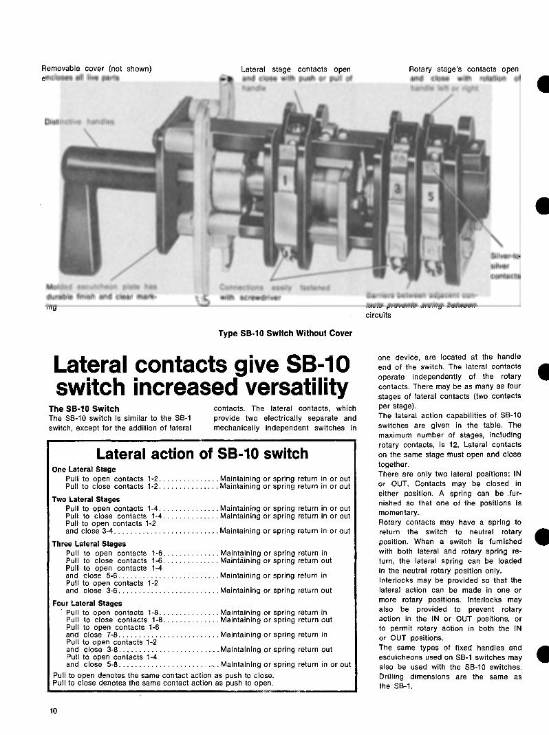
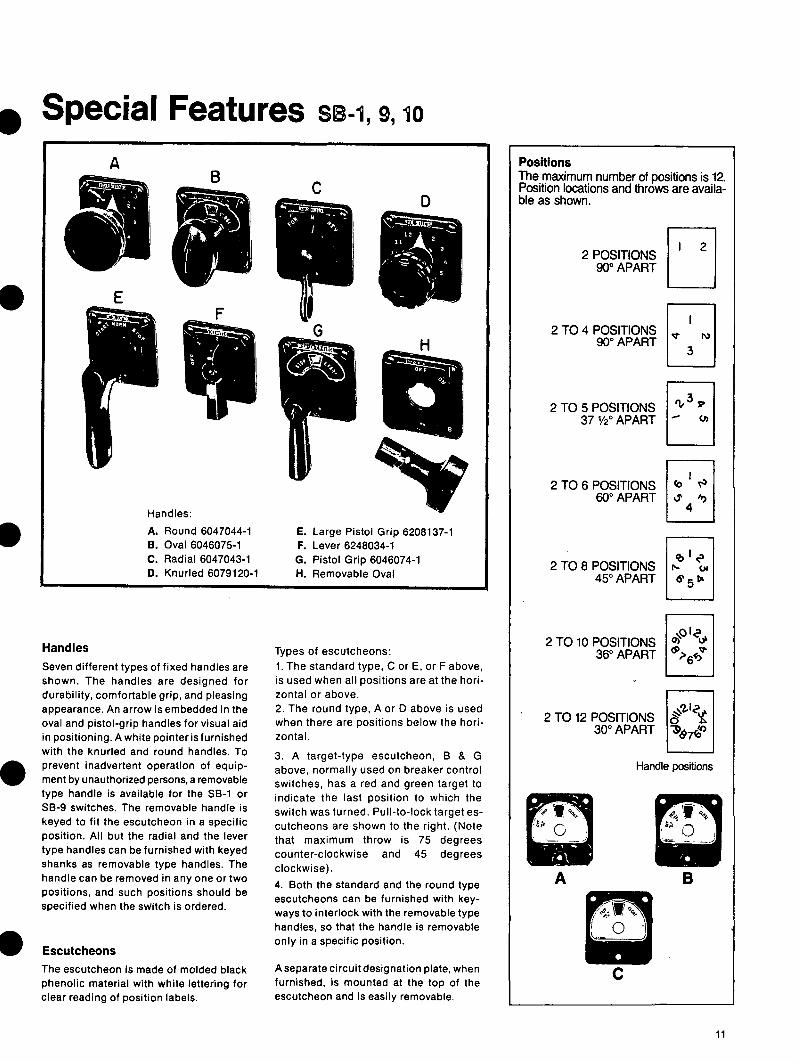