GE Power Plant Design with FOUNDATION™ Fieldbus …€¦ · GEA31803 GE Power Plant Design with...
12
© 2015 General Electric Company. All Rights Reserved. This material may not be copied or distributed in whole or in part, without prior permission of the copyright owner. GE Power Plant Design with FOUNDATION™ Fieldbus Technology Mark Disch Flor Rivas John Wainwright GE Power & Water GEA31803 June 2015
Transcript of GE Power Plant Design with FOUNDATION™ Fieldbus …€¦ · GEA31803 GE Power Plant Design with...

© 2015 General Electric Company. All Rights Reserved. This material may not be copied or distributed in whole or in part, without prior permission of the copyright owner.
GE Power Plant Design with FOUNDATION™ Fieldbus Technology
Mark Disch Flor Rivas John Wainwright
GE Power & Water GEA31803June 2015

2
GEA31803 GE Power Plant Design with FOUNDATION™ Fieldbus Technology
© 2015 General Electric Company. All Rights Reserved. This material may not be copied or distributed in whole or in part, without prior permission of the copyright owner.
Contents
Executive Summary . . . . . . . . . . . . . . . . . . . . . . . . . . . . . . . . . . . . . . . . . . . . . . . . . . . . . . . . . . . . . . . . . 3
Overview of Digital Bus Technology . . . . . . . . . . . . . . . . . . . . . . . . . . . . . . . . . . . . . . . . . . . . . . . . . . 3
GE’s Digital Bus Application Philosophy . . . . . . . . . . . . . . . . . . . . . . . . . . . . . . . . . . . . . . . . . . . . . . 3
Benefits of FOUNDATION™ Fieldbus vs Traditional Wiring . . . . . . . . . . . . . . . . . . . . . . . . . . . . 4
Application of FOUNDATION™ Fieldbus Across GE Power Plants . . . . . . . . . . . . . . . . . . . . . . 6
GE Experience with FOUNDATION™ Fieldbus . . . . . . . . . . . . . . . . . . . . . . . . . . . . . . . . . . . . . . . . 7
Conclusion . . . . . . . . . . . . . . . . . . . . . . . . . . . . . . . . . . . . . . . . . . . . . . . . . . . . . . . . . . . . . . . . . . . . . . . . . . 9
Appendix . . . . . . . . . . . . . . . . . . . . . . . . . . . . . . . . . . . . . . . . . . . . . . . . . . . . . . . . . . . . . . . . . . . . . . . . . . 10
3
GE Power Plant Design with FOUNDATION™ Fieldbus Technology GEA31803
© 2015 General Electric Company. All Rights Reserved. This material may not be copied or distributed in whole or in part, without prior permission of the copyright owner.
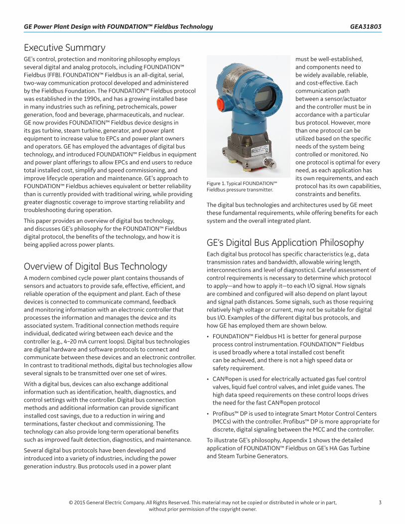
Executive SummaryGE’s control, protection and monitoring philosophy employs several digital and analog protocols, including FOUNDATION™ Fieldbus (FFB). FOUNDATION™ Fieldbus is an all-digital, serial, two-way communication protocol developed and administered by the Fieldbus Foundation. The FOUNDATION™ Fieldbus protocol was established in the 1990s, and has a growing installed base in many industries such as refining, petrochemicals, power generation, food and beverage, pharmaceuticals, and nuclear. GE now provides FOUNDATION™ Fieldbus device designs in its gas turbine, steam turbine, generator, and power plant equipment to increase value to EPCs and power plant owners and operators. GE has employed the advantages of digital bus technology, and introduced FOUNDATION™ Fieldbus in equipment and power plant offerings to allow EPCs and end users to reduce total installed cost, simplify and speed commissioning, and improve lifecycle operation and maintenance. GE’s approach to FOUNDATION™ Fieldbus achieves equivalent or better reliability than is currently provided with traditional wiring, while providing greater diagnostic coverage to improve starting reliability and troubleshooting during operation.
This paper provides an overview of digital bus technology, and discusses GE’s philosophy for the FOUNDATION™ Fieldbus digital protocol, the benefits of the technology, and how it is being applied across power plants.
Overview of Digital Bus TechnologyA modern combined cycle power plant contains thousands of sensors and actuators to provide safe, effective, efficient, and reliable operation of the equipment and plant. Each of these devices is connected to communicate command, feedback and monitoring information with an electronic controller that processes the information and manages the device and its associated system. Traditional connection methods require individual, dedicated wiring between each device and the controller (e.g., 4–20 mA current loops). Digital bus technologies are digital hardware and software protocols to connect and communicate between these devices and an electronic controller. In contrast to traditional methods, digital bus technologies allow several signals to be transmitted over one set of wires.
With a digital bus, devices can also exchange additional information such as identification, health, diagnostics, and control settings with the controller. Digital bus connection methods and additional information can provide significant installed cost savings, due to a reduction in wiring and terminations, faster checkout and commissioning. The technology can also provide long-term operational benefits such as improved fault detection, diagnostics, and maintenance.
Several digital bus protocols have been developed and introduced into a variety of industries, including the power generation industry. Bus protocols used in a power plant
must be well-established, and components need to be widely available, reliable, and cost-effective. Each communication path between a sensor/actuator and the controller must be in accordance with a particular bus protocol. However, more than one protocol can be utilized based on the specific needs of the system being controlled or monitored. No one protocol is optimal for every need, as each application has its own requirements, and each protocol has its own capabilities, constraints and benefits.
The digital bus technologies and architectures used by GE meet these fundamental requirements, while offering benefits for each system and the overall integrated plant.
GE’s Digital Bus Application PhilosophyEach digital bus protocol has specific characteristics (e.g., data transmission rates and bandwidth, allowable wiring length, interconnections and level of diagnostics). Careful assessment of control requirements is necessary to determine which protocol to apply—and how to apply it—to each I/O signal. How signals are combined and configured will also depend on plant layout and signal path distances. Some signals, such as those requiring relatively high voltage or current, may not be suitable for digital bus I/O. Examples of the different digital bus protocols, and how GE has employed them are shown below.
• FOUNDATION™ Fieldbus H1 is better for general purpose process control instrumentation. FOUNDATION™ Fieldbus is used broadly where a total installed cost benefit can be achieved, and there is not a high speed data or safety requirement.
• CAN®open is used for electrically actuated gas fuel control valves, liquid fuel control valves, and inlet guide vanes. The high data speed requirements on these control loops drives the need for the fast CAN®open protocol
• Profibus™ DP is used to integrate Smart Motor Control Centers (MCCs) with the controller. Profibus™ DP is more appropriate for discrete, digital signaling between the MCC and the controller.
To illustrate GE’s philosophy, Appendix 1 shows the detailed application of FOUNDATION™ Fieldbus on GE’s HA Gas Turbine and Steam Turbine Generators.
Figure 1. Typical FOUNDATION™ Fieldbus pressure transmitter.

4
GEA31803 GE Power Plant Design with FOUNDATION™ Fieldbus Technology
© 2015 General Electric Company. All Rights Reserved. This material may not be copied or distributed in whole or in part, without prior permission of the copyright owner.
Benefits of FOUNDATION™ Fieldbus vs Traditional WiringThe three key stages of a power plant lifecycle are planning, building, and operating. GE’s adoption of FOUNDATION™ Fieldbus provides benefits to EPCs and end users in the building and operating stages. The building stage includes installation and commissioning.
Installation
The objective of the installation phase is to safely construct the power plant in a predictable, short timeframe while minimizing material and labor costs.
Use of FOUNDATION™ Fieldbus reduces installation materials and labor costs by allowing multiple signals to be transmitted over a single pair of wires. Less wire is needed. Fewer terminations are required. Many terminations are made with simple plug-in connectors. At times, the cost differential can also lead to other changes that improve reliability and/or reduce maintenance costs.
For example, GE’s W86 Structured Product Line (SPL) generator uses FOUNDATION™ Fieldbus to connect 123 single and dual channel thermocouples and RTDs, providing 183 temperature signals, to the control. Where previously 300 wires would have been wired from the generator all the way to the controller, now temperature sensors are wired at the GE factory to FFB Temperature Transmitters and Device Couplers mounted on the generator, and only eight wires are run between the generator and the controller. This saves significant field installation material and labor costs, and time (see Figure 2 and Figure 3).
The cost of the high amount of traditional wiring previously led to a design where only one channel of a dual channel thermocouple was wired back to the controller. A failure in a dual-channel device would result in a reduced number of temperature signals and possibly a maintenance action to re-land connections to a working channel in a junction box mounted on the generator. FOUNDATION™ Fieldbus allows transition from the failed channel to an operating channel, providing continued full instrumentation coverage without a time consuming maintenance action.
Applying FOUNDATION™ Fieldbus broadly, a GE 1x1 single shaft 9HA power plant with can be built with approximately 60% less wiring and fewer, simpler terminations. With appropriate plant-level engineering, junction boxes are replaced by plug and play device couplers, cable trays are reduced in size, and conduits are replaced by wire baskets. These factors can achieve a total installed cost (TIC) savings of over $1M, compared to a plant with traditional device/control interconnections. FOUNDATION™ Fieldbus instruments may cost more than traditionally-wired devices, however the installation cost savings more than offsets increased component costs.
Commissioning
The objective of the commissioning phase is to safely bring the installed equipment and plant to commercial operation in a predictable, short timeframe while minimizing material and labor costs.
FOUNDATION™ Fieldbus reduces commissioning time and costs by facilitating the pre-commissioning of subsystem skids, enabling faster wiring checkout at the site, and speeding site commissioning. This reduces pre-commissioning time by approximately 20 to 30%, and cold loop checks (point to point wire signal checks) by 60%, as well as the likelihood and cost of any rework.
Generator temperature measurement with FOUNDATION™ FieldbusGenerator temperature measurement with traditional I/O
Figure 2. Comparison of interconnecting wiring between Traditional I/O and FOUNDATION™ Fieldbus I/O designs.
Figure 3. W86 SPL Generator temperature sensors factory-wired to generator-mounted FFB temperature transmitters.
5
GE Power Plant Design with FOUNDATION™ Fieldbus Technology GEA31803
© 2015 General Electric Company. All Rights Reserved. This material may not be copied or distributed in whole or in part, without prior permission of the copyright owner.
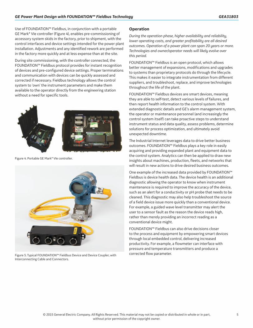
Use of FOUNDATION™ Fieldbus, in conjunction with a portable GE Mark* VIe controller (Figure 4), enables pre-commissioning of accessory system skids in the factory, prior to shipment, with the control interfaces and device settings intended for the power plant installation. Adjustments and any identified rework are performed in the factory more quickly and at less expense than at the site.
During site commissioning, with the controller connected, the FOUNDATION™ Fieldbus protocol provides for instant recognition of devices and pre-configured device settings. Proper terminations and communication with devices can be quickly assessed and corrected if necessary. Fieldbus technology allows the control system to ‘own’ the instrument parameters and make them available to the operator directly from the engineering station without a need for specific tools.
Operation
During the operation phase, higher availability and reliability, lower operating costs, and greater profitability are all desired outcomes. Operation of a power plant can span 20 years or more. Technologies and owner/operator needs will likely evolve over this period.
FOUNDATION™ Fieldbus is an open protocol, which allows better management of expansions, modifications and upgrades to systems than proprietary protocols do through the lifecycle. This makes it easier to integrate instrumentation from different suppliers, and troubleshoot, replace, and improve technologies throughout the life of the plant.
FOUNDATION™ Fieldbus devices are smart devices, meaning they are able to self-test, detect various levels of failures, and then report health information to the control system. With extended diagnostic details and GE’s alarm management system, the operator or maintenance personnel (and increasingly the control system itself) can take proactive steps to understand instrument status and data quality, assess problems, determine solutions for process optimization, and ultimately avoid unexpected downtime.
The Industrial Internet leverages data to drive better business outcomes. FOUNDATION™ Fieldbus plays a key role in easily acquiring and providing expanded plant and equipment data to the control system. Analytics can then be applied to draw new insights about machines, production, fleets, and networks that will result in new actions to drive desired business outcomes.
One example of the increased data provided by FOUNDATION™ Fieldbus is device health data. The device health is an additional diagnostic allowing the operator to know when instrument maintenance is required to improve the accuracy of the device, such as an alert for a conductivity or pH probe that needs to be cleaned. This diagnostic may also help troubleshoot the source of a field device issue more quickly than a conventional device. For example, a guided wave level transmitter may alert the user to a sensor fault as the reason the device reads high, rather than merely providing an incorrect reading as a conventional device might.
FOUNDATION™ Fieldbus can also drive decisions closer to the process and equipment by empowering smart devices through local embedded control, delivering increased productivity. For example, a flowmeter can interface with pressure and temperature transmitters and produce a corrected flow parameter.
Figure 4. Portable GE Mark* VIe controller.
Figure 5. Typical FOUNDATION™ Fieldbus Device and Device Coupler, with Interconnecting Cable and Connectors.

6
GEA31803 GE Power Plant Design with FOUNDATION™ Fieldbus Technology
© 2015 General Electric Company. All Rights Reserved. This material may not be copied or distributed in whole or in part, without prior permission of the copyright owner.
Application of FOUNDATION™ Fieldbus Across GE Power PlantsGE has selectively applied FOUNDATION™ Fieldbus technology across the power plant to create the most benefit for EPCs and power plant owners and operators. One of the goals of applying FOUNDATION™ Fieldbus is to reduce the overall total installed cost by reducing wiring. Therefore it may not make sense to apply FOUNDATION™ Fieldbus devices where an installation cost benefit cannot be achieved. Typically, an installation cost benefit can be achieved where there are at least 4 devices in proximity to each other (e.g. accessory skids).
For safety critical control loops and control loops that have very fast data rate requirements, traditional wiring is maintained since fieldbus technologies are intrinsically not as fast as hard-wiring. Fast data rates are typically a requirement of some gas turbine control loops. Most Steam Turbine and Balance of Plant control loops do not exceed the FOUNDATION™ Fieldbus data rate capability, so FOUNDATION™ Fieldbus is used more widely in these applications. Figure 6 shows an I/O breakdown for a typical 1x1 single shaft 9HA plant. FOUNDATION™ Fieldbus devices make up a large percentage of total I/O.
GE has standard guidelines for implementing FOUNDATION™ Fieldbus in Balance of Plant equipment not supplied by GE. Collaboration with EPCs and end customers is required to provide a reliable design, and to maximize the benefits of the technology for the BOP.
System Reliability
When choosing a digital bus technology such as FOUNDATION™ Fieldbus, the impact of system and component reliability must be considered. GE has developed an architecture to provide equivalent or better system reliability where FOUNDATION™
Fieldbus is used. Similar to a traditional hard-wired design, the system with digital bus technology is engineered with a component redundancy scheme so that no single point failure will interrupt plant operations.
GE has chosen not to modify existing SIL safety system designs, focusing on digital bus technology for other systems.
Architecture - Sensor to the Controller
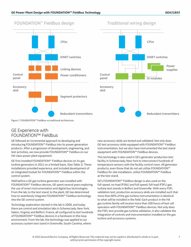
Figure 7 shows a side-by-side comparison of a typical FOUNDATION™ Fieldbus sensor-to-controller architecture with a traditional hard-wired architecture.
Looking at the two architectures side by side, the only differences are seen between the sensor/transmitter and the IONET switches in the controller.
At the accessory skid, redundant transmitters are wired to separate devices. Hard-wired transmitters are wired to a junction box where the signals are passed through, and the FOUNDATION™ Fieldbus transmitters are wired to a segment protector where the signals are passed through. In both scenarios, redundant power sources are located within the control panel. The primary difference in system reliability lies in the difference in reliability of a linking device versus that of an I/O processing module. GE’s approach is to make the linking devices hot-backup redundant to provide a highly reliable system.
The GE design with FOUNDATION™ Fieldbus maintains the same redundancy schemes as our traditional wired designs so that no single point failures will interrupt operation, but the component layout also provides equal or better reliability from sensor to controller.
FOUNDATION™ Fieldbus Traditional wiring Profibus™ CAN®open
Figure 6. GE 9HA Plant Control Element Type.
7
GE Power Plant Design with FOUNDATION™ Fieldbus Technology GEA31803
© 2015 General Electric Company. All Rights Reserved. This material may not be copied or distributed in whole or in part, without prior permission of the copyright owner.
GE Experience with FOUNDATION™ FieldbusGE followed an incremental approach to developing and introducing FOUNDATION™ Fieldbus into its power generation products. After a progression of development, engineering, and test activities, we now provide FOUNDATION™ Fieldbus on our HA-class power plant equipment.
GE first installed FOUNDATION™ Fieldbus devices on its gas turbine generators in 2011 on a limited basis. (See Table 1). These installations provided experience, and included development of an integrated toolset for FOUNDATION™ Fieldbus within the control system.
Well before a GE gas turbine generator was installed with FOUNDATION™ Fieldbus devices, GE spent several years exploring the use of smart instrumentation and digital bus technologies. From the lab, to the test stand, to the plant, GE has determined how to seamlessly integrate FOUNDATION™ Fieldbus technology into the GE control system.
Technology exploration started in the lab in 2000, and today there are control and simulation labs in Schenectady, New York; Salem, Virginia; and Belfort, France, all configured to test hundreds of FOUNDATION™ Fieldbus devices in a hardware-in-the-loop environment. From the lab, the technology was applied to our accessory system test stand in Greenville, South Carolina, where
new accessory skids are tested and validated. Not only does GE test accessory skids equipped with FOUNDATION™ Fieldbus instrumentation, but we also have instrumented the test stand equipment with FOUNDATION™ Fieldbus devices.
This technology is also used in GE’s generator production test facility in Schenectady, New York to interconnect hundreds of temperature sensors with the facility control room. All generator products, even those that do not yet utilize FOUNDATION™ Fieldbus for site installation, utilize FOUNDATION™ Fieldbus at the test stand.
GE’s FOUNDATION™ Fieldbus design is also used on the full-speed, no-load (FSNL) and full-speed, full-load (FSFL) gas turbine test stands in Belfort and Greenville. With every FSFL validation test, production accessory skids are installed such that more than 80% of the gas turbine instrumentation is identical to what will be installed in the field. Each product in the HA gas turbine family will receive more than 200 hours of test cell operation with FOUNDATION™ Fieldbus devices. Not only does the FSFL test provide gas turbine validation, it also validates the integration of controls and instrumentation installed on the gas turbine and accessory systems.
Figure 7. FOUNDATION™ Fieldbus vs traditional architecture.
8
GEA31803 GE Power Plant Design with FOUNDATION™ Fieldbus Technology
© 2015 General Electric Company. All Rights Reserved. This material may not be copied or distributed in whole or in part, without prior permission of the copyright owner.
In 2014, the first 9HA gas turbine was installed on the FSFL test stand, fully instrumented with over 150 FOUNDATION™ Fieldbus devices. During approximately 215 hours of testing, the troubleshooting and starting reliability benefits of FOUNDATION™ Fieldbus technology were illustrated multiple times. For example, the diagnostic information that is integrated into the control system provided insights into maintenance needs for a valve that was not properly getting instrument air. That diagnostic would not have been visible in the control system if the valve were not using
a smart FOUNDATION™ Fieldbus transmitter. This allowed the test stand team to correct the maintenance issue long before the start button was pressed.
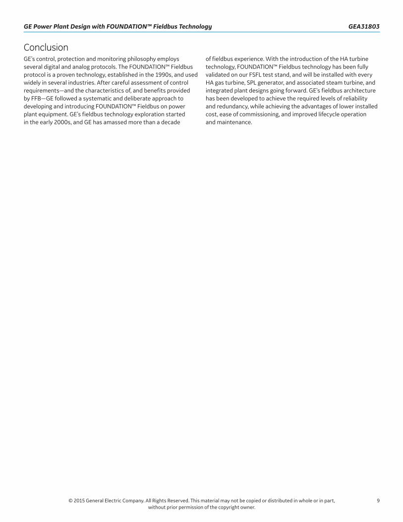
FOUNDATION™ Fieldbus is part of GE Power & Water and GE Oil & Gas control philosophy. Going forward in 2015 and beyond, the experience base for FOUNDATION™ Fieldbus on GE Power Plants will grow significantly. Table 1 summarizes GE’s existing and upcoming installations using FOUNDATION™ Fieldbus devices.
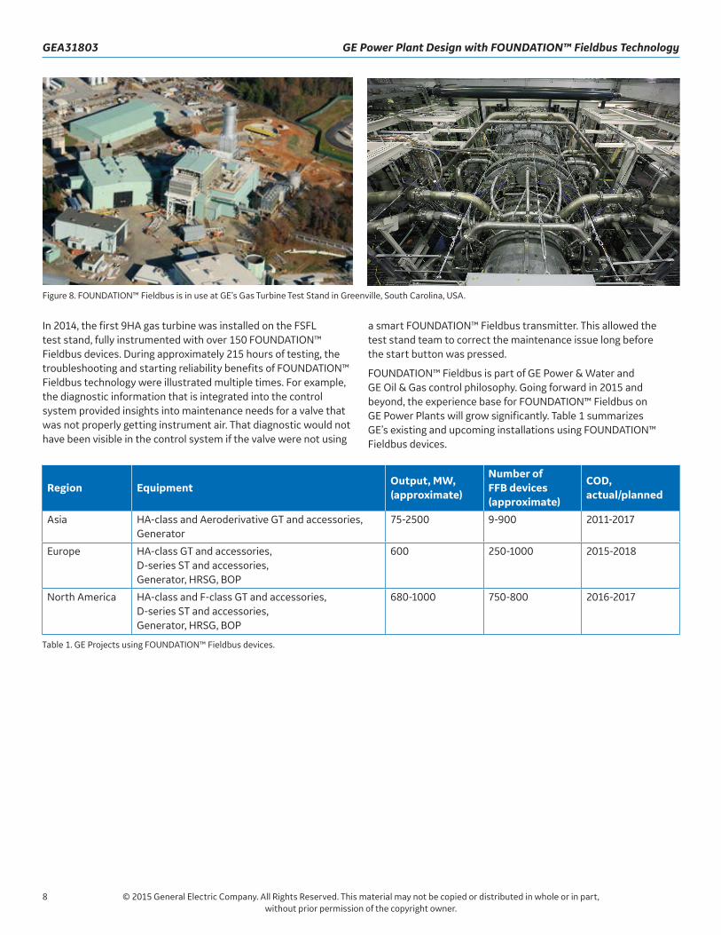
Figure 8. FOUNDATION™ Fieldbus is in use at GE’s Gas Turbine Test Stand in Greenville, South Carolina, USA.
Region EquipmentOutput, MW, (approximate)
Number of FFB devices (approximate)
COD, actual/planned
Asia HA-class and Aeroderivative GT and accessories, Generator
75-2500 9-900 2011-2017
Europe HA-class GT and accessories, D-series ST and accessories, Generator, HRSG, BOP
600 250-1000 2015-2018
North America HA-class and F-class GT and accessories, D-series ST and accessories, Generator, HRSG, BOP
680-1000 750-800 2016-2017
Table 1. GE Projects using FOUNDATION™ Fieldbus devices.
9
GE Power Plant Design with FOUNDATION™ Fieldbus Technology GEA31803
© 2015 General Electric Company. All Rights Reserved. This material may not be copied or distributed in whole or in part, without prior permission of the copyright owner.
ConclusionGE’s control, protection and monitoring philosophy employs several digital and analog protocols. The FOUNDATION™ Fieldbus protocol is a proven technology, established in the 1990s, and used widely in several industries. After careful assessment of control requirements—and the characteristics of, and benefits provided by FFB—GE followed a systematic and deliberate approach to developing and introducing FOUNDATION™ Fieldbus on power plant equipment. GE’s fieldbus technology exploration started in the early 2000s, and GE has amassed more than a decade
of fieldbus experience. With the introduction of the HA turbine technology, FOUNDATION™ Fieldbus technology has been fully validated on our FSFL test stand, and will be installed with every HA gas turbine, SPL generator, and associated steam turbine, and integrated plant designs going forward. GE’s fieldbus architecture has been developed to achieve the required levels of reliability and redundancy, while achieving the advantages of lower installed cost, ease of commissioning, and improved lifecycle operation and maintenance.

10
GEA31803 GE Power Plant Design with FOUNDATION™ Fieldbus Technology
© 2015 General Electric Company. All Rights Reserved. This material may not be copied or distributed in whole or in part, without prior permission of the copyright owner.
AppendixApplication of FOUNDATION™ Fieldbus in HA Gas Turbine Generator and Steam Turbine Generator
Gas Turbine and Generator
IO SystemFOUNDATION™ Fieldbus
CAN®open Profibus™ Traditional IO
Lube oil X X X
Cooling and sealing air X X X
Air processing unit X
Cooling water X X X
Fuel gas X X X
Liquid fuel X X X X
Inlet bleed heating X
Heating and ventilation X X X
Water wash/false start drain X
Inlet guide vanes/variable stator vanes X X
Inlet and exhaust pressure transmitters X X
Hazardous gas X
Gas fuel purge X X
Combustion dynamics monitoring X
Fuel performance heater X
Fuel gas absolute separator X
Gas scrubber X
Gas chromatograph X
Fire protection system X
Evaporative cooler X
Exhaust diffuser vent fans X
Temperature matching X
Inlet damper control X
Miscellaneous turbine devices X X
LCI X
Generator temperature monitoring X
Generator gas monitoring X

11
GE Power Plant Design with FOUNDATION™ Fieldbus Technology GEA31803
© 2015 General Electric Company. All Rights Reserved. This material may not be copied or distributed in whole or in part, without prior permission of the copyright owner.
Steam Turbine and Generator
IO SystemFOUNDATION™ Fieldbus
CAN®open Profibus™ Traditional IO
Lube oil X X X
Hydraulic/lift oil X X X
Seal, seal oil X X X
Steam valves X
Steam condition X X
Steam drains X
Steam turbine supervisory system X X
Steam turbine rotor speed X
Hood spray X
Turning gear X X
Generator temperature monitoring X
Generator gas monitoring X

*Trademark of General Electric CompanyFOUNDATION™ is a trademark of Fieldbus Inc.CAN®open is a trademark of the CAN in Automation User’s Group.Profibus™ is a trademark of the Profibus User Organization.
GEA31803 (6/2015)
Imagination at work