GE Infrastructure Water and Process Technologies · GE Infrastructure Water and Process...
37
GE Infrastructure Water and Process Technologies Merlin™ Point of Use Drinking Water System Application Guide for Water Treatment Professionals
Transcript of GE Infrastructure Water and Process Technologies · GE Infrastructure Water and Process...

GE Infrastructure Water and Process Technologies
Merlin™
Point of Use
Drinking Water SystemApplication Guide for Water Treatment Professionals
TABLE OF CONTENTSINTRODUCTION 3
MERLIN DESCRIPTION 4
SYSTEM PERFORMANCE 5
THE MERLIN FLOW SYSTEM 16
MERLIN BOOSTER PUMP 17
PREFILTER 18
MEMBRANE LIFE 20
MERLIN PERMEATE STORAGE SYSTEMS 22
SALT DIFFUSION 23
COMMERCIAL AND INDUSTRIAL APPLICATIONS 29
TROUBLESHOOTING 31
WARRANTY 33
FLOW ESTIMATION WORKSHEETS 34
2 TABLE OF CONTENTSRev B

INTRODUCTIONThis application guide presents guidelines and technical information on the Merlin, a continuous flow reverse osmosis (RO) water filtration system designed for residential and light commercial applications
Water treatment professionals should use this guide as an education tool to help determine the best application of the Merlin RO system.
Information is included on reverse osmosis systems in general. The Merlin differences are highlighted where appropriate.
This Application Guide is not intended to be used as an installation or maintenance manual.
An Installation and Mainenance Manual, PN 1262366, is available from your Merlin supplier.
The information provided here is not intended to be the answer to every question the water treatment professional will have. If you have applications that are unusual, we would like to hear from you.
INTRODUCTION 3Rev B

MERLIN DESCRIPTIONThe Merlin is a point of use reverse osmosis system that provides continuous, on-demand water. It features a breakthrough high flow-rate technology developed by GE Infrastructure Water & Process Technologies. The Merlin RO system is designed for residential use and light commercial applications including:
• Restaurants
• Coffee Shops
• Aquariums
• Grocery Misters.
The Merlin system is the most revolutionary innovation in point-of-use RO technology since the first such units were introduced. Water treatment professionals can now offer their residential and light commercial customers an exclusive improvement over other water purification methods.
Figure 1
4 MERLIN DESCRIPTIONRev B
SYSTEM PERFORMANCE
THE MERLIN SWEET SPOT
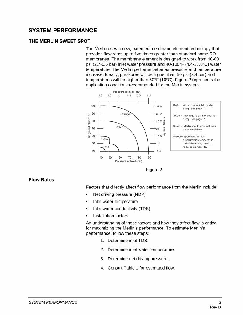
The Merlin uses a new, patented membrane element technology that provides flow rates up to five times greater than standard home RO membranes. The membrane element is designed to work from 40-80 psi (2.7-5.5 bar) inlet water pressure and 40-100°F (4.4-37.8°C) water temperature. The Merlin performs better as pressure and temperature increase. Ideally, pressures will be higher than 50 psi (3.4 bar) and temperatures will be higher than 50°F (10°C). Figure 2 represents the application conditions recommended for the Merlin system.
Figure 2
Flow Rates
Factors that directly affect flow performance from the Merlin include:
• Net driving pressure (NDP)
• Inlet water temperature
• Inlet water conductivity (TDS)
• Installation factors
An understanding of these factors and how they affect flow is critical for maximizing the Merlin’s performance. To estimate Merlin’s performance, follow these steps:
1. Determine inlet TDS.
2. Determine inlet water temperature.
3. Determine net driving pressure.
4. Consult Table 1 for estimated flow.
40 50 60 70 80 90
100
90
80
70
60
50
40
Pressure at Inlet (psi)
Deg
rees
Fah
renh
eit
Red
Yellow
Green
Orange
Red - will require an inlet booster pump. See page 11.
Yellow - may require an inlet booster pump. See page 11.
Green - Merlin should work well with these conditions.
Orange - application in high pressure/high temperature installations may result in reduced element life.
37.8
32.2
26.7
21.1
15.6
10
4.4
Deg
rees
Cel
sius
2.8 3.5 4.1 4.8 5.5 6.2 Pressure at Inlet (bar)
SYSTEM PERFORMANCE 5Rev B
Understanding Net Driving Pressure
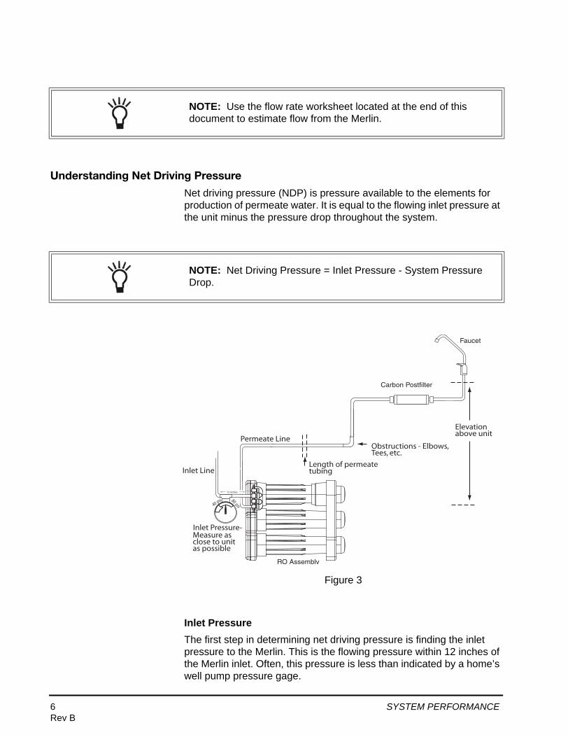
Net driving pressure (NDP) is pressure available to the elements for production of permeate water. It is equal to the flowing inlet pressure at the unit minus the pressure drop throughout the system.
Figure 3
Inlet PressureThe first step in determining net driving pressure is finding the inlet pressure to the Merlin. This is the flowing pressure within 12 inches of the Merlin inlet. Often, this pressure is less than indicated by a home’s well pump pressure gage.
NOTE: Use the flow rate worksheet located at the end of this document to estimate flow from the Merlin.
NOTE: Net Driving Pressure = Inlet Pressure - System Pressure Drop.
RO Assembly
Faucet
Carbon Postfilter
Elevation above unit
Length of permeate tubing
Permeate Line
Inlet Pressure-Measure as close to unit as possible
Obstructions - Elbows, Tees, etc.
40 psi 80 psi
12 inches
Inlet Line
6 SYSTEM PERFORMANCERev B
System Pressure DropEstimating system pressure drop is the second step in determining net driving pressure. Pressure drops are created by:
• Tubing friction losses• Obstructions• Elevation differences• Post Filter• Faucet• Osmonic pressure
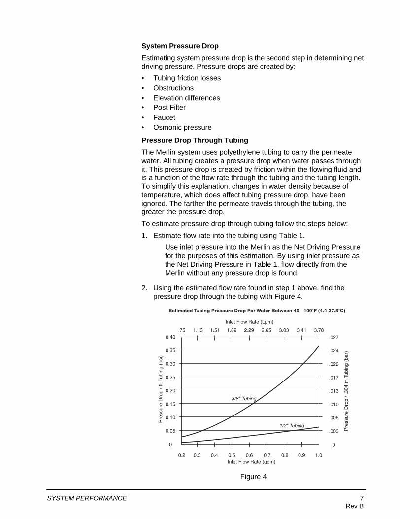
Pressure Drop Through TubingThe Merlin system uses polyethylene tubing to carry the permeate water. All tubing creates a pressure drop when water passes through it. This pressure drop is created by friction within the flowing fluid and is a function of the flow rate through the tubing and the tubing length. To simplify this explanation, changes in water density because of temperature, which does affect tubing pressure drop, have been ignored. The farther the permeate travels through the tubing, the greater the pressure drop.
To estimate pressure drop through tubing follow the steps below:
1. Estimate flow rate into the tubing using Table 1.
Use inlet pressure into the Merlin as the Net Driving Pressure for the purposes of this estimation. By using inlet pressure as the Net Driving Pressure in Table 1, flow directly from the Merlin without any pressure drop is found.
2. Using the estimated flow rate found in step 1 above, find the pressure drop through the tubing with Figure 4.
Figure 4
0.2 0.3 0.4 0.5 0.6 0.7 0.8 0.9 1.0
0.40
0.35
0.30
0.25
0.20
0.15
0.10
0.05
0
Inlet Flow Rate (gpm)
Pre
ssur
e D
rop
/ ft.
Tubi
ng (
psi)
1/2" Tubing
3/8" Tubing
.027
.024
.020
.017
.013
.010
.006
.003
0
.75 1.13 1.51 1.89 2.29 2.65 3.03 3.41 3.78
Inlet Flow Rate (Lpm)
Pre
ssur
e D
rop
/ .30
4 m
Tub
ing
(bar
)
Estimated Tubing Pressure Drop For Water Between 40 - 100˚F (4.4-37.8˚C)
SYSTEM PERFORMANCE 7Rev B

Pressure Drop Through ObstructionsEvery obstruction or fitting in the line will cause a small amount of pressure drop. We recommend keeping connections or obstructions in the permeate line to a minimum. These include items such as tees, valves, step-down adapters, elbows, compression fittings, etc.
We recommend subtracting 1/2 psi (0.034 bar) of pressure drop per fitting used.
Figure 5
NOTE: Do not use 1/4-inch OD tubing anwhere in the installation, including runs to ice makers. Larger tubing diameters produce less pressure drop and increase system performance.
EXAMPLE:Q: A Merlin will be installed with inlet conditions that will produce
0.5 gpm, based on Table 1. The installation requires 20 ft of permeate tubing. Find the tubing pressure drop.
A: Tubing pressure drop for this installation will be 0.11 psi/ft of 3/8-inch tubing or 0.02 psi/ft of 1/2-inch tubing according to Figure 4. Because 20 ft of tubing will be used, the total tubing pressure drop is:
For 3/8-inch tubing: 0.11 psi/ft X 20 ft = 2.2 psi tubing pressure dropFor 1/2-inch tubing: 0.02 psi/10 ft X 20 ft = 0.4 psi tubing pressure drop
weuro iefos qweru qweri uiroweurio wier
weuro iefos qweru qweri uiroweurio wier
weuro iefos qweru qweri uiroweurio wier
Tee ElbowStepdownFitting
CompressionFittingValve
8 SYSTEM PERFORMANCERev B

Pressure Drop Through ElevationFaucet elevation can play a major factor in Merlin performance. Faucet elevation produces a backpressure on the Merlin unit from the elevated column of water. We recommend minimizing elevation differences between the Merlin unit and water faucet. Estimate pressure drop due to elevation according to the following equation:
Pressure drop = 0.43 psi/ft X elevation in feet
(Pressure drop = 0.1 bar/m X elevation in meters)
Figure 6
EXAMPLE:Q: A Merlin will be installed with 1 tee, 2 valves, and 1 elbow.
Find the obstruction pressure drop.
A: The obstruction pressure drop is found as follows:
4 fittings X 1/2 psi (0.034 bar) each = 2 psi (0.137 bar) obstruction pressure drop
weuro iefos qweru qweri uiroweurio wier
weuro iefos qweru qweri uiroweurio wier
weuro iefos qweru qweri uiroweurio wier
Floor
Dispensing Faucet
RO Assembly
Elevation
SYSTEM PERFORMANCE 9Rev B

Pressure Drop Through Post FilterThe Merlin post filter is custom designed to reduce the amount of pressure drop as much as possible. The Merlin post filter is designed to provide no more than a 3 psi (0.21 bar) drop when brand new. Using other post filter/post treatment methods may cause significantly higher drops in pressure.
Figure 7
The Merlin post filter uses Granular Activation Carbon (GAC). Like all other RO systems, the post filter is critical for providing the best tasting permeate water.
Pressure Drop Through FaucetTo estimate pressure drop through the Merlin faucet follow the steps below:
1. Estimate flow rate into the faucet using Table 1.
Use inlet pressure into the Merlin minus the total pressure drop caused by tubing, elevation, post filter, and obstructions as the Net Driving Pressure for the purposes of this estimation.
2. Using the estimated flow rate found in step 1 above, find the pressure drop through the tubing with Figure 8.
EXAMPLE:Q: A Merlin will be installed with 8 feet (2.4 m) elevation difference
between the Merlin and the faucet. Find the elevation pressure drop.
A: The elevation pressure drop is found as follows:
8 feet X 0.43 psi/foot = 3.5 psi elevation pressure drop2.4 m X 0.1 bar/m = .24 bar elevation pressure drop
weuro iefos qweru qweri uiroweurio wier
weuro iefos qweru qweri uiroweurio wier
weuro iefos qweru qweri uiroweurio wier
EXAMPLE:Q: A Merlin will be installed with one post filter. Find the post filter
pressure drop.
A: The post filter pressure drop is found as follows:
1 post filter X 3 psi = 3 psi post filter pressure drop1 post filter X 0.21 bar = 2.1 bar elevation pressure drop
weuro iefos qweru qweri uiroweurio wier
weuro iefos qweru qweri uiroweurio wier
weuro iefos qweru qweri uiroweurio wier
10 SYSTEM PERFORMANCERev B

Figure 8
Flow InformationApproximate flow rates from the Merlin system are shown for certain net driving pressure and temperature conditions in Table 1. Data shown is based on water containing 750 ppm NaCl. Losses because of osmonic pressure are included in the Table 1 data. No further adjustment needs to be made to account for osmonic pressure losses.
0.2 0.3 0.4 0.5 0.6 0.7 0.8 0.9 1.0
16
14
12
10
8
6
4
2
0
Inlet Flow Rate (gpm)
Fauc
et P
ress
ure
Dro
p (p
si)
1.10
.97
.83
.69
.55
.41
.27
.14
0
.75 1.13 1.51 1.89 2.29 2.65 3.03 3.41 3.78
Inlet Flow Rate (Lpm)
Fauc
et P
ress
ure
Dro
p (b
ar)
Estimated Faucet Pressure Drop For Water Between 40 - 100˚F (4.5 - 38˚C)
EXAMPLE:Q: A Merlin will be installed with the estimated flow into a faucet at
0.4 gpm (0.27 bar). Find the faucet pressure drop.
A: According to Figure 8, the faucet pressure drop will be 3.8 psi (0.26 bar).
weuro iefos qweru qweri uiroweurio wier
weuro iefos qweru qweri uiroweurio wier
weuro iefos qweru qweri uiroweurio wier
SYSTEM PERFORMANCE 11Rev B

Use the flow rate worksheet located at the end of this document to estimate flow from the Merlin.
In The Followiing Example:A Merlin will be installed under the following conditions:
Table 1 - Merlin System Flow Rates (gpm), Based on 750 ppm NaCl Inlet Watera
Net Driving Pressureb, psi [bar]
Temperature °F [°C]
75[5.2]
70[4.8]
65[4.5]
60[4.1]
55[3.8]
50[3.4]
45[3.1]
40[2.8]
35[2.4]
80 [27] 1.03 0.95 0.88 0.81 0.74 0.67 0.60 0.53 0.46
70 [21] 0.89 0.83 0.77 0.71 0.65 0.58 0.52 0.46 0.40
60 [16] 0.77 0.72 0.66 0.61 0.55 0.50 0.44 0.39 0.33
50 [10] 0.63 0.59 0.54 0.49 0.45 0.40 0.36 0.31 0.26
a. To adjust data to actual conditions, multiply measured TDS by -0.0002 and add 0.15. Add answer to Table data to achieve actual flow rate. Estimated flow change from 750 ppm NaCl = -.0002 X measured TDS + 0.15
b. Net Driving Pressure = Flowing Inlet Pressure – System Pressure Drop
NOTE: Pressure drop throughout the system is caused by such things as frictional tubing losses, vertical tubing runs, post filter, faucet, and obstructions. See section on system pressure drop for more detailed information.
NOTE: Actual system performance may vary due to manufacturing tolerances and installation factors.
Inlet Water TDS 300 ppm
Inlet Water Temperature 50°F (10°C)
Flowing Inlet Pressure 60 psi (4.1bar)
3/8-inch Tubing Length 15 ft (4.6 m)
Obstruction(s) In Permeate Line One 90° elbow
Elevation Difference Between Merlin And Dispensing Location 6 ft (1.8 m)
Post Filter Used? Yes
Faucet Used? Yes
12 SYSTEM PERFORMANCERev B

HOW TO DETERMINE RATE OF FLOW FROM THE MERLIN SYSTEM - NORTH AMERICAN
Example
Inlet Water TDS (measured) 300 ppm
Inlet Water Temperature 50°F
Inlet Pressure 60 psi
3/8-inch Tubing 15 ft long
Obstructions in Permeate Line One 90° elbow
Elevation Difference Between Merlin and Faucet 6 ft.
Post Filter? Yes
Faucet? Yes
Assigned Values
Pressure Drop per Obstruction 0.5 psi
Pressure Drop per Postfilter 3 psi
Pressure Drop in Elevation 0.43 psi per ft
(feet Faucet is above Merlin)
1. Determine the Inlet TDS = 300 ppm
2. Determine the Inlet Water Temperature = 50 °F
3. Determine the Net Driving Pressure of the Merlin system
Net Driving Pressure = Inlet Pressure - System Pressure Drop (Follow instructions below)
3A. Calculate the Flow Rate Adjustment Factor
This factor will be used with Table 1 to adjust the TDS of Inlet Water from 750 ppm to 300 ppm.
-0.0002 (300 ppm) + 0.15 = 0.09 gpm
3B. Calculate the Tubing Pressure Drop
Inlet Pressure = 60 psi
Water Temp = 50°F
Use Table 1 to estimate flow rate, 750 ppm NaCl @ 50°F and 60 psi = 0.49 gpm
Adjust Table data for actual TDS using the Flow Rate Adjustment Factor 0.09 gpm
Tubing Flow Rate = 0.49 gpm + 0.09 gpm = 0.58 gpm @ 300 ppm NaCl
Use Figure 4 to determine the pressure drop for 1 ft. tubing = 0.138 psi
Tubing Pressure Drop for 15 ft = 15 x 0.138 psi = 2.07 psi
3C. Calculate the Obstruction Pressure Drop
1 obstruction (the elbow) X (0.5 psi) = 0.5 psi
3D. Calculate Elevation Pressure Drop
6 ft elevation X 0.43 psi/ft = 2.58 psi
3E. Calculate Postfilter Pressure Drop
1 postfilter X 3 psi = 3 psi
3F. Calculate Faucet Pressure Drop
60 psi - 2.07 psi - 0.5 psi - 2.58 psi - 3 psi = 51.85 psi
Use Table 1 to estimate flow rate, 750 ppm NaCl @ 50°F and 51.85 psi = 0.40 gpm
Adjust Table Data for actual TDS using the Flow Rate Adjustment Factor 0.09 gpm
0.36 gpm + 0.09 gpm = 0.45 gpm @ 300 ppm NaCl
e 8 and the Inlet Flow Rate of 0.49 gpm to estimate the Faucet Pressure Drop = 4.5 psi
3G. Calculate the System Pressure Drop
(System Pressure Drop = Tubing PD + Obstruction PD + Elevation PD + Postfilter PD + Faucet PD
2.07 psi + 0.5 psi + 2.58 psi + 3 psi + 4.5psi = 12.65 psi
3H. Determine the Net Driving Pressure Drop
(Net Driving Pressure = Merlin Inlet Pressure - System Pressure Drop)
60 psi - 12.65psi = 47.35 psi
4. Determine the Merlin Flow Rate
Use Table 1 to estimate flow rate, 750 ppm NaCl @ 47.35psi and 50°F = 0.38gpm
Adjust Table Data for actual TDS using the Flow Rate Adjustment Factor 0.09 gpm
0.38 gpm + 0.09 gpm = 0.47 gpm
TOTAL MERLIN FLOW RATE = 0.47 gpm
g gp p
p p p p p
p p
Actual results may vary.
SYSTEM PERFORMANCE 13Rev B

HOW TO DETERMINE RATE OF FLOW FROM THE MERLIN SYSTEM - WORLD
Example
Inlet Water TDS (measured) 300 ppm
Inlet Water Temperature 10°C
Inlet Pressure 4.1 bar
3/8-inch Tubing 4.6 m long
Obstructions in Permeate Line One 90° elbow
Elevation Difference Between Merlin and Faucet 1.8 m
Post Filter? Yes
Faucet? Yes
Assigned Values
Pressure Drop per Obstruction 0.03 bar
Pressure Drop per Postfilter 0.21 bar
Pressure Drop in Elevation 0.095 bar per meter
(meters Faucet is above Merlin)
1. Determine the Inlet TDS = 300 ppm
2. Determine the Inlet Water Temperature = 10°C
3. Determine the Net Driving Pressure of the Merlin system
Net Driving Pressure = Inlet Pressure - System Pressure Drop
3A. Calculate the Flow Rate Adjustment Factor
This factor will be used with Table 1 to adjust the TDS of Inlet Water from 750 ppm to 300 ppm.
-0.0002 (300 ppm) + 0.15 = 0.34 Lpm
3B. Calculate the Tubing Pressure Drop
Inlet Pressure = 4.1 bar
Water Temp = 10°C
Use Table 1 to estimate flow rate, 750 ppm NaCl @ 10°C and 4.1 bar = 1.85 Lpm
Adjust Table data for actual TDS using the Flow Rate Adjustment Factor 0.34 Lpm
Tubing Flow Rate = 1.85 Lpm + 0.34 Lpm = 2.19 Lpm @ 300 ppm NaCl
Use Figure 4 to determine the pressure drop for .304 meter tubing = 0.0095 bar
Tubing Pressure Drop for 4.6 m = 4.6/0.304 x 0.0095 bar = 0.143 bar
3C. Calculate the Obstruction Pressure Drop
1 obstruction (the elbow) X 0.03 bar = 0.03 bar
3D. Calculate Elevation Pressure Drop
1.83 m elevation X 0.095 bar = 0.18 bar
3E. Calculate Postfilter Pressure Drop
1 postfilter X 0.21 bar = 0.21 bar
3F. Calculate Faucet Pressure Drop
4.1 bar - 0.14 bar - 0.03 bar - 0.18 bar - 0.21 bar = 3.54 bar
Use Table 1 to estimate flow rate, 750 ppm NaCl @ 10°C and 3.54 bar = 1.32 Lpm
Adjust Table Data for actual TDS using the Flow Rate Adjustment Factor 0.34 Lpm
1.32 Lpm + 0.34 Lpm = 1.66 Lpm @ 300 ppm NaCl
Use Figure 8 and the Inlet Flow Rate of 1.66 Lpm to estimate the Faucet Pressure Drop = 0.31 bar
3G. Calculate the System Pressure Drop
(System Pressure Drop = Tubing PD + Obstruction PD + Elevation PD + Postfilter PD + Faucet PD
0.14 bar + 0.03 bar + 0.18 bar + 0.21 bar + 0.31 bar = 0.87bar
3H. Determine the Net Driving Pressure
(Net Driving Pressure = Merlin Inlet Pressure - System Pressure Drop)
4.1 bar - 0.87 bar = 3.23 bar
4. Determine the Merlin Flow Rate
Use Table 1 to estimate flow rate, 750 ppm NaCl @ 3.23 bar and 10°C = 1.44 Lpm
Adjust Table Data for actual TDS using the Flow Rate Adjustment Factor 0.34 Lpm
1.44 Lpm + 0.34 Lpm = 1.78 Lpm
TOTAL MERLIN FLOW RATE = 1.78 Lpm
Actual results may vary.
14 SYSTEM PERFORMANCERev B

Flow Information for Standard InstallationsFor typical single faucet under-the-sink Merlin installations using only the components shipped in the box, the following flow rates can be expected. This information assumes 4 feet of 3/8-inch permeate tubing, 2 feet elevation difference, use of the faucet as shipped, and no additional obstructions or pressure drop. Data shown is based on water containing 750 ppm NaCl.
Table 2 - Merlin System Flow Rates, gpm, based on 750 ppm NaCl Inlet Watera Typical Single Faucet Installation
Flowing Inlet Pressure psi [bar]
Temperature °F [°C]
80[5.5]
75[5.2]
70[4.8]
65[4.5]
60[4.1]
55[3.8]
50[3.4]
45[3.1]
40[2.8]
80 [27] 0.77 0.73 0.68 0.64 0.59 0.55 0.50 0.45 0.40
70 [21] 0.72 0.68 0.63 0.59 0.55 0.50 0.46 0.41 0.36
60 [16] 0.65 0.61 0.57 0.53 0.49 0.45 0.40 0.36 0.31
50 [10] 0.57 0.53 0.49 0.45 0.42 0.38 0.34 0.30 0.26
a. To adjust data to actual conditions, multiply measured TDS by -0.0002 and add 0.15. Add answer to Table data to achieve actual flow rate. Estimated flow change from 750 ppm NaCl = -.0002 X measured TDS + 0.15
NOTE: Actual system performance may vary because of manufacturing tolerances and installation factors.
SYSTEM PERFORMANCE 15Rev B
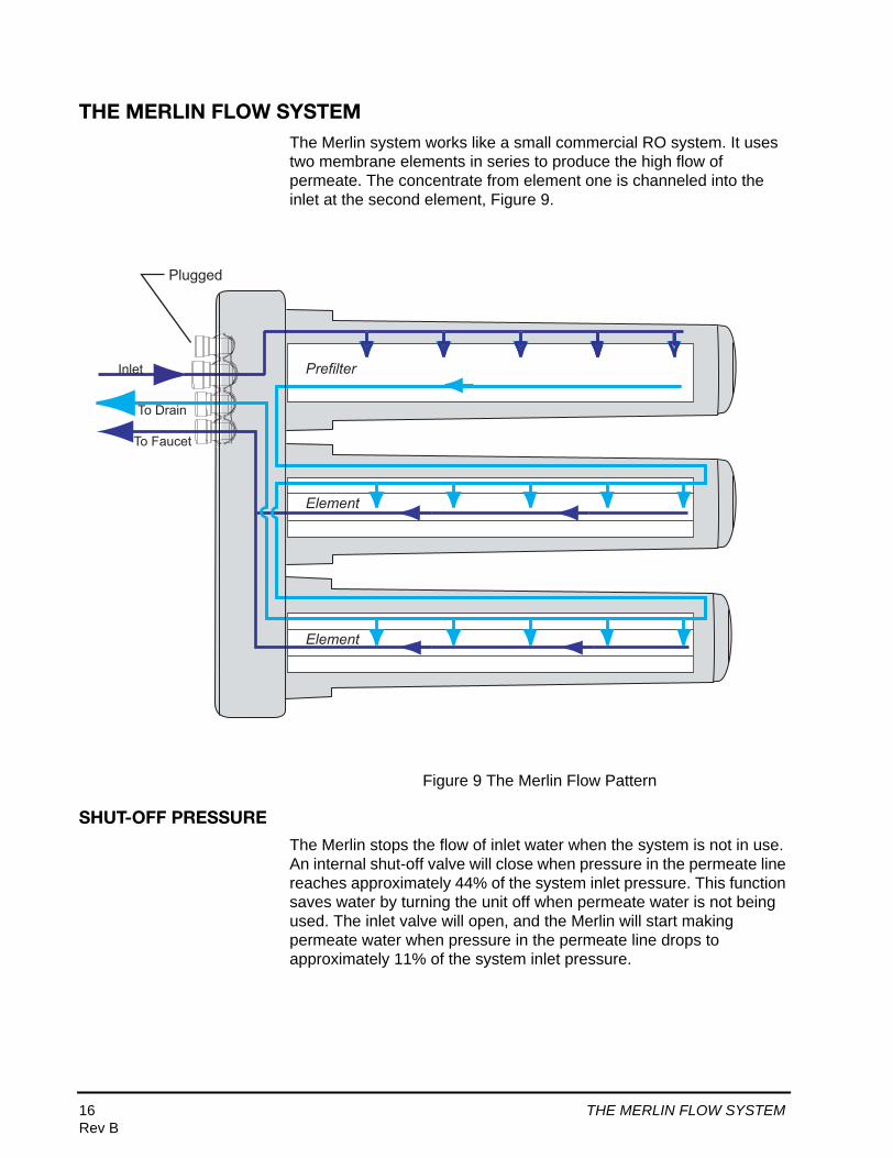
THE MERLIN FLOW SYSTEMThe Merlin system works like a small commercial RO system. It uses two membrane elements in series to produce the high flow of permeate. The concentrate from element one is channeled into the inlet at the second element, Figure 9.
Figure 9 The Merlin Flow Pattern
SHUT-OFF PRESSURE
The Merlin stops the flow of inlet water when the system is not in use. An internal shut-off valve will close when pressure in the permeate line reaches approximately 44% of the system inlet pressure. This function saves water by turning the unit off when permeate water is not being used. The inlet valve will open, and the Merlin will start making permeate water when pressure in the permeate line drops to approximately 11% of the system inlet pressure.
Prefilter
Plugged
Element
Element
Inlet
To Drain
To Faucet
16 THE MERLIN FLOW SYSTEMRev B

MERLIN BOOSTER PUMPFor lower pressure and/or low temperature applications, a pressure activated booster pump for Merlin is available. Refer to Figure 2 for help determining when applications may require a booster pump to improve system performance.
To install, connect the pump to the 1/2-inch inlet tubing, and plug in the motor. The pump will automatically turn on and off whenever the Merlin is producing water.
The Merlin booster pump is a variable speed pump designed to produce water pressure at 62 to 68 psi (4.27 to 4.69 bar) regardless of the inlet pressure. As with all pumps, make sure the water flow rate is at least 2 gpm (7.6 Lpm).
Pump SpecificationsInlet water pre-pump pressure range - 20 to 60 psi (1.38 to 4.14 bar)
Pump outlet pressure - 60 to 68 psi (4.14 to 4.69 bar)
Necessary water flow for proper pump operation - 2 to 4 gpm (7.6 to 15.1 Lpm)
Pump electrical ratings - 110 to 120 VAC, 60 Hz, 500 watt
Pump duty cycle - intermittent operation - 1 hour
Figure 10
We recommend using only the Merlin provided booster pump. Other pumps may result in reduced membrane element or system life.
Motor Shell at 1.5 AmpsThermal Shut-OffTemperature
0 10 20 30 40 50 60 70 80 90 100 110 120
200
180
160
140
120
100
80
60
TIME (Minutes)
Pum
p H
ou
sin
gTe
mp
erat
ure
(˚F)
PUMP HEAT RISE
NOTE: The Merlin booster pump is a great way to increase flow for low pressure applications. The pump will also help increase TDS rejection and system efficiency.
MERLIN BOOSTER PUMP 17Rev B

PREFILTERThe Merlin RO membrane elements will not tolerate long-term exposure to chlorine. All chlorine must be eliminated from the inlet water before contacting the RO elements.
Standard Carbon Block PrefilterThe standard Merlin prefilter is a carbon block with 5-micron nominal sediment reduction capability.
Limits For Standard Prefilter1 ppm chlorine—incoming water
3 NTU of sediment—incoming water
0 ppm of iron—incoming water
5 micron - nominal sediment removal capability
Prefilter Life CalculationThe Merlin filter is rated for 5000 gallons (18,900 liters) of inlet water. Use the following formula to estimate prefilter life:
Example:
Commercial ApplicationsCommercial applications will use far more water than most residential applications. In commercial applications, the prefilter may only last a few days. We recommend not using the standard carbon prefilter on applications that will use more than 20 gallons (75 liters) of permeate water per day, Figure 11.
Prefilter life(days)
50004 X Average Daily Permeate Usage (gals)
=
EXAMPLE:Q: A household uses 4 gallons permeate water per day.
Estimate the prefilter life.
A:weuro iefos qweru qweri uiroweurio wier
weuro iefos qweru qweri uiroweurio wier
weuro iefos qweru qweri uiroweurio wier
Prefilter life(days)
50004 X 4 gals
= = 312.5 days
18 PREFILTERRev B

For these higher water use commercial applications, we recommend using a high capacity carbon cartridge or backwash carbon filter as pretreatment to the Merlin. Remove the standard Merlin carbon block filter from the system.
An alternate 10-micron nominal high capacity sediment prefilter is available for Merlin. This filter can be used for commercial or well water applications where no chlorine is present in the Merlin inlet water.
This sediment filter is interchangeable with the standard Merlin carbon prefilter for applications without chlorine.
Figure 11
EXAMPLE:Q: A light commercial application uses 200 gals (757 liters)
permeate water per day. Estimate the prefilter life.
A:weuro iefos qweru qweri uiroweurio wier
weuro iefos qweru qweri uiroweurio wier
weuro iefos qweru qweri uiroweurio wier
Prefilter life(days)
50004 X 200 gals
= = 6.25 days
Standard Merlin Prefilter5-micron nominal3 NTU max turbidity5000 gal capacity
1 ppm chlorine max at inlet
Alternate Merlin Filter for Commercial or Well Applications10-micron nominalTBD NTU max turbidityTBD gal capacity
0 ppm chlorine max at inlet
NOTE: Some applications may have water turbidity or iron levels that negatively affect prefilter life. If a prefilter clogs very quickly, consider additional pretreatment before the system.
PREFILTER 19Rev B
MEMBRANE LIFEThe Merlin uses a new, patented, RO membrane technology, not an ultra or nanofiltration membrane.
It is a standard thin film membrane (TFM) style that is not tolerant of chlorine.
Maximizing Membrane Element LifePretreatment is the key to maximizing the Merlin membrane element life, like all reverse osmosis membranes. To maximize element life, adhere to the following inlet water conditions.
Chlorine at inlet to element — 0 ppm
Inlet hardness to system — less than 10 grain, 0 grain optimal
Inlet iron to system — less than .1 ppm, 0 ppm optimal
Inlet manganese — less than .05 ppm, 0 ppm optimal
Temperature — 40 to 100°F (4.4 to 37.8°C)
MERLIN RECOVERY VS. EFFICIENCY
One performance measure for a home RO system is the recovery/efficiency rate. This is a published amount of permeate water produced as a product of total inlet water used. The higher the recovery of an RO membrane system, the less waste water is sent to drain.
• Recovery is the measured permeate (product) water volume produced as a percentage of inlet water consumed. This is measured directly from the membrane element.
• Efficiency is the measured permeate (product) water volume produced as a percentage of inlet water consumed.
But,
Efficiency is measured taking into account the complete system. This measurement includes the storage tank and any other pressure drop in the system.
Efficiency is the real-world performance that the consumer will experience. Therefore it is the best measurement of system performance.
The Problem With Systems That Have Storage TanksTraditional home RO systems that utilize a tank may be able to boast 18-25% recovery, however, most operate at much lower efficiency.
As storage tank systems produce permeate water, the tank exerts pressure drop on the membrane as the tank fills and tank pressure increases. This pressure drop decreases the membrane elements recovery significantly as the tank fills. In many cases, the system’s efficiency will drop as low as 5% when the tank is near full.
20 MEMBRANE LIFERev B

The Merlin AdvantageSince the Merlin requires no storage tank, its membrane element performs at the optimal recovery rate at all times. This makes the Merlin’s efficiency the same as the Merlin’s recovery. Because of this, the Merlin sends significantly less waste water to the drain than tradional home RO systems with a tank.
This is a huge advantage in areas where water conservation is critical.
Figure 12 Merlin vs. RO Efficiency with Three Gallon Tank
The Proof Is In The NumbersBelow is a waste water calculation to show the amount of waste water produced to make 3 gallons of permeate water.
Which system is better for the environment?
Consider that the average consumer is using only 8-12 oz. of water at a time. An RO system with a storage tank generally is operating under 10% efficiency!
Table 3
Standard Home RO Merlin RO
Gallon 11 gallon of permeate water @ 20% efficiency = 4 gallons of water to drain
1 gallon permeate @ 25% efficiency = 3 gallons to drain
Gallon 21 gallon of permeate water at 10% efficiency =9 gallons of water to drain
1 gallon permeate @ 25% efficiency = 3 gallons to drain
Gallon 31 gallon of permeate water @ 5% efficiency =19 gallons of water to drain
1 gallon permeate @ 25% efficiency =3 gallons to drain
Results 32 total gallons of water to drain 9 total gallons to drain
1 2 3 4 5 6 7(3.8) (7.6) (11.4) (15.1) (18.9) (22.7) (26.5)
30
25
20
15
10
5
Gallons (Liters) of Permeate Water Produced
% E
ffic
iency
Tank is Full
Merlin RO System
RO System With Storage Tank
Tank is Empty
MEMBRANE LIFE 21Rev B

MERLIN PERMEATE STORAGE SYSTEMSThe Merlin is designed to provide an average 1/2 gpm (1.89 Lpm) continuous flow rate at NSF/ANSI 58 conditions. Some applications may require an intermittent flow rate higher than the 1/2 gpm rate. This can be accomplished by using a permeate storage tank.
Type Of Storage TankPressurized storage tanks create a backpressure on the system that will reduce performance. For this reason we recommend the use of an atmospheric storage tank with a float shutoff for storing permeate water as shown in Figure 13.
Figure 13
Merlin RO Assembly
Inlet
PressurePump
To Point of Use
Vented to atmosphere
22 MERLIN PERMEATE STORAGE SYSTEMSRev B
SALT DIFFUSIONLike all reverse osmosis systems, the Merlin uses semi-permeable membrane elements to filter contaminants. When pressurized, this membrane element allows water with low salt concentrations to pass through, leaving higher concentrations of salt on the opposite side of the element. Unpressurized, naturally occurring diffusion takes place between the low salt permeate water and higher salt concentrate water. This process, which happens in all RO systems when not in operation, begins to equalize salt concentrations on each side of the element. After approximately two hours of inactivity, measured TDS rejection of the permeate water held within the RO membrane elements and manifold will have dropped below steady-state rejection levels.
Salt Diffusion in Traditional RO SystemsIn a typical home RO system, the salt-diffused permeate water created through periods of inactivity is mixed into the storage tank. Over time, the salt concentration within the storage tank slightly increases. The end users are eventually forced to use salt-diffused water. This is one reason why most RO manufacturers recommend flushing holding tanks on a weekly basis — it minimizes, but does not eliminate, salt diffusion effects.
Salt Diffusion in the MerlinAfter extended periods of inactivity in the Merlin system, any salt-diffused water will be exhausted through the faucet when the system is operated. After this water is flushed from the system, the RO continues producing water at typical steady-state high rejection levels. The Merlin, therefore, allows users to eliminate the effects of salt diffusion by simply running their system for 1 to 3 minutes after extended periods of inactivity. For most end users, the salt diffusion will be undetectable. For those users who monitor rejection levels, a spike of water with higher conductivity may be seen when testing is conducted immediately after an extended period of inactivity. Because of salt diffusion, rejection levels should be tested when the system has reached steady-state operation.
Merlin Flush SystemFor highly demanding applications that require an alternate method to lessen the effects of salt diffusion, a Merlin flush kit is available. This kit includes a small tank that connects to the 1/4-inch light blue elbow on the Merlin. The kit forces permeate water to flush the high salt concentrate water from the membrane elements. By doing this, the system rests with low salt concentrations on both sides of the elements. Because low salt concentrations remain on each side of the membrane, salt diffusion is greatly reduced. The kit uses approximately 0.7 gallons (2.5 liters) of permeate water to flush the membrane elements each time it operates. Figure 14 through Figure 18 illustrate the flush kit operation.
SALT DIFFUSION 23Rev B
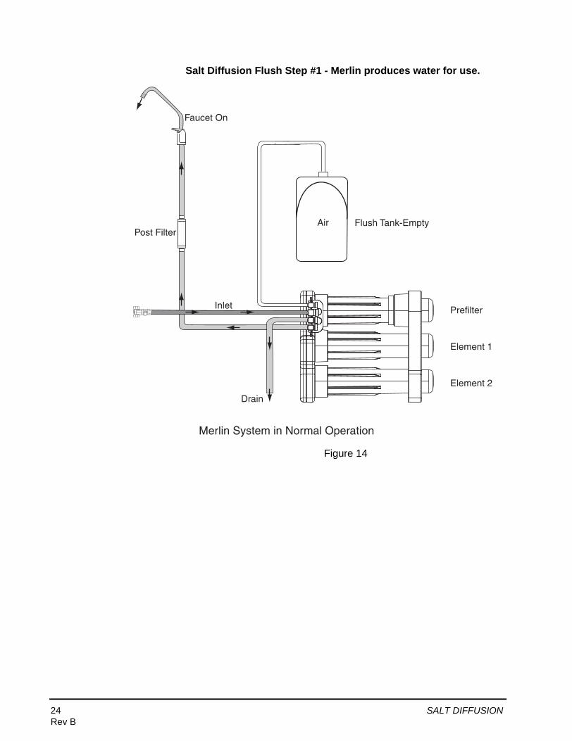
Salt Diffusion Flush Step #1 - Merlin produces water for use.
Figure 14
Flush Tank-Empty
Faucet On
Inlet
Drain
Merlin System in Normal Operation
Air
Prefilter
Element 1
Element 2
Post Filter
24 SALT DIFFUSIONRev B

Salt Diffusion Flush Step #2 - Accumulator begins to fill.
Figure 15
Flush Tank-Filling with Water
Faucet Off
Inlet
Drain
Merlin System is Producing Permeate Water for Flush
Prefilter
Element 1
Element 2
Post Filter
Air compresses
SALT DIFFUSION 25Rev B

Salt Diffusion Flush Step #3 - Accumulator is filled.
Figure 16
Flush Tank-FullPressure Equalizes
Faucet Off
Inlet
Drain
Merlin System Stops Producing Permeate Water
Prefilter
Element 1
Element 2
Post FilterWater
26 SALT DIFFUSIONRev B

Salt Diffusion Flush Step #4 - Membrane flush begins.
Figure 17
Faucet Off
Inlet
Drain
Merlin System Begins Flush
Prefilter
Element 1
Element 2
Water Permeate water is directed back to unit. Permeate water begins flushing high TDS water out of system to drain.
Post Filter
SALT DIFFUSION 27Rev B

Salt Diffusion Flush Step #5 - System stops.
Figure 18
Flush Tank-All water is purgedfrom Tank
Faucet Off
Inlet
Drain
Merlin System Is Off
Air
Prefilter
Element 1
Element 2
Low TDS water has flushed out the inlet side of the elements. Complete process may take 3 to 8 minutes.
Post Filter
28 SALT DIFFUSIONRev B
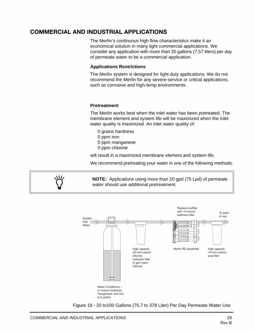
COMMERCIAL AND INDUSTRIAL APPLICATIONSThe Merlin’s continuous high flow characteristics make it an economical solution in many light commercial applications. We consider any application with more than 20 gallons (7.57 liters) per day of permeate water to be a commercial application.
Applications RestrictionsThe Merlin system is designed for light-duty applications. We do not recommend the Merlin for any severe-service or critical applications, such as corrosive and high-temp environments.
PretreatmentThe Merlin works best when the inlet water has been pretreated. The membrane element and system life will be maximized when the inlet water quality is maximized. An inlet water quality of:
0 grains hardness0 ppm iron0 ppm manganese0 ppm chlorine
will result in a maximized membrane element and system life.
We recommend pretreating your water in one of the following methods:
Figure 19 - 20 to100 Gallons (75.7 to 378 Liter) Per Day Permeate Water Use
NOTE: Applications using more than 20 gpd (75 Lpd) of permeate water should use additional pretreatment.
Merlin RO Assembly
Water Conditioner -to reduce hardness,manganese, and ironto 0 grains
SystemInlet Water
Replace prefilter with 10-micron sediment filter
High capacity 10-inch carbon post filter
To point of use
High capacity 20-inch carbon chlorine reduction filter to get 0 ppm chlorine
COMMERCIAL AND INDUSTRIAL APPLICATIONS 29Rev B

Figure 20 - 100 to 720 Gallons (378 to 2725 Liters) Per Day Permeate Water Use
Merlin RO Assembly
Carbon Backwash Filter -size according to wateruse needs - reduce to 0ppm chlorine
Water Softener - size according towater use needs - reduce hardness,manganese, and iron to 0 grains
SystemInlet Water
Replace prefilter with 10-micron sediment filter
High capacity post filter
Shutoff Valve-use when permeatesystems are in regeneration
To point of use
NOTE: Additional pretreatment may be necessary for high turbidity, high iron, or pH imbalanced water.
30 COMMERCIAL AND INDUSTRIAL APPLICATIONSRev B

TROUBLESHOOTING
Issue Possible Cause Corrective Action
Low permeate flow 1. Net driving pressure and/or inlet temperature too low.
2. Plugged prefilter.
3. Scaled or fouled RO membrane.
4. Faucet not adjusted properly.
5. Plugged postfilter.
6. Leak or kink in permeate line.
1. Measure and record actual flow rate from faucet.
2. Determine net driving pressure. Refer to page 6.
3. Using net driving pressure and inlet temperature, compare actual flow rate to predicted flow as shown in Table 1.
4. Reduce pressure losses due to tubing, elevation, and fittings.
5. Install booster pump for applications where an increase in inlet pressure will provide acceptable flow according to Figure 2.
6. Replace plugged prefilter. Consider sediment prefilter for non-chlorinated applications.
7. Replace membrane elements.
8. Adjust faucet t-bar setting as tight as possible without causing leaks from the faucet.
9. If flow into the postfilter is acceptable, replace postfilter.
10. Find and repair leak or kink.
Concentrate water runs to drain after faucet shut off
1. Pressure created by trapped air in the system affecting operation of the automatic shut off valve.
2. Clogged prefilter reducing pressure in permeate line.
3. Leak in permeate line reducing pressure.
1. Relieve air lock by removing prefilter sump, allowing water do drain from sump. Then reconnect prefilter sump.
2. Inspect prefilter. Replace clogged prefilter.
3. Find and repair leak.
COMMERCIAL AND INDUSTRIAL APPLICATIONS 31Rev B
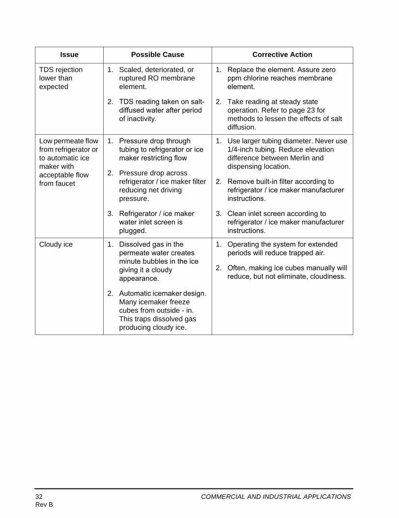
TDS rejection lower than expected
1. Scaled, deteriorated, or ruptured RO membrane element.
2. TDS reading taken on salt-diffused water after period of inactivity.
1. Replace the element. Assure zero ppm chlorine reaches membrane element.
2. Take reading at steady state operation. Refer to page 23 for methods to lessen the effects of salt diffusion.
Low permeate flow from refrigerator or to automatic ice maker with acceptable flow from faucet
1. Pressure drop through tubing to refrigerator or ice maker restricting flow
2. Pressure drop across refrigerator / ice maker filter reducing net driving pressure.
3. Refrigerator / ice maker water inlet screen is plugged.
1. Use larger tubing diameter. Never use 1/4-inch tubing. Reduce elevation difference between Merlin and dispensing location.
2. Remove built-in filter according to refrigerator / ice maker manufacturer instructions.
3. Clean inlet screen according to refrigerator / ice maker manufacturer instructions.
Cloudy ice 1. Dissolved gas in the permeate water creates minute bubbles in the ice giving it a cloudy appearance.
2. Automatic icemaker design. Many icemaker freeze cubes from outside - in. This traps dissolved gas producing cloudy ice.
1. Operating the system for extended periods will reduce trapped air.
2. Often, making ice cubes manually will reduce, but not eliminate, cloudiness.
Issue Possible Cause Corrective Action
32 COMMERCIAL AND INDUSTRIAL APPLICATIONSRev B

WARRANTY
Commercial Vs. Residential WarrantyThe Merlin is designed as a home RO system. The continuous flow nature of the Merlin system makes it a prime candidate for many light commercial applications. Most light commercial applications cause more wear-and-tear on the Merlin system. Because of this, we offer a commercial warranty to cover light commercial applications, as well as a residential warranty.
We consider any application that uses more than 20 gallons (7.57 liters) per day of permeate water to be a commercial application.
Residential applications—36-month warranty
Commercial applications—12-month warranty
System WarrantyGE Infrastructure Water & Process Technologies will replace any plastic component on the system that has failed because of a manufacturing or design defect. Failures caused by misapplication, or incorrect system installation by the installing dealer cannot be honored. GE Infrastructure Water & Process Technologies may require proof of correct application/installation before warranting the product.
Membrane Element WarrantyThe Merlin membrane element is warranted for manufacturing or design defects for a 12-month period from the date of manufacture, when installation inlet water conditions are within the published limits. Elements that fail prematurely due to fouling from iron, hardness, manganese or chlorine cannot be warranted.
Pre/post Filter Warranty
The Merlin pre/post carbon filters are not warranted due to the very high variability in inlet water conditions that may cause significant life deviation from the published carbon filter life.
COMMERCIAL AND INDUSTRIAL APPLICATIONS 33Rev B

GE Infrastructure Water & Process TechnologiesMerlin™ Point of Use Drinking Water System Limited Warranty
A. GE Infrastructure Water & Process Technologies (Manufacturer) warrants that the Merlin drinking water system sold hereunder will be free from defects in material or workmanship at the time of shipment from the GE Osmonics factory. The Manufacturer warrants the Merlin drinking water system in residential applications for a period of 36 months from the date of manufacture. This warranty does not extent to the system’s replaceable components including:
a. Carbon/sediment prefilter cartridgeb. Carbon post filter cartridge/housingc. Merlin membrane element cartridges will be warranted from a period of 12 months
from the date of shipment from the Manufacturer’s facility or 18 months from the date of manufacture of the membrane element. The membrane element warranty will not be valid if installed improperly, and must be operated on a chlorine, ozone, bromine and iodine-free domestic water supply in accordance with the published operating parameters for the Merlin system. The system’s prefilter, when used/serviced correctly, will protect the membrane elements from chlorine.
B. Before using the Merlin system, the user shall determine the suitability of the product for his/her intended purposes, and shall assume all risk and liability in connection of the system therewith. The Manufacturer shall not be liable for any injury, loss or damage, direct or indirect, special or consequential, arising out of the use of, misuse, misapplication or the inability to use the system.
a. The Manufacturer’s only obligation shall be to issue credit against the purchase or replacement of the equipment proved to be defective in material or workmanship.
b. The warranty is only applicable if upon demand by the Manufacturer, the Buyer proves to the Manufacturer’s satisfaction that:
c. No repairs or alterations were made to the system or goods without expressed written consent by the Manufacturer.
d. The defect is due solely to the materials or workmanship of the goods.e. The defect was not caused by any act of the Buyer or its agents.f. The defect was not caused by any manner beyond the reasonable control of the
Manufacturer, including, without limitation, accident or normal wear and tear.g. The system was installed in an application within the published operating specifi-
cations for the Merlin system.h. The system was installed using only supplied or recommended supplier compo-
nents as described in the Merlin system documentation.C. The warranty does not extend to any goods not manufactured by GE Infrastructure Water
& Process Technologies even though supplied by GE Infrastructure Water & Process Technologies, nor does it extend to any second-hand or reconditioned goods.
D. If the Merlin System is used for commercial or industrial purposes, GE Infrastructure Water & Process Technologies warrants the Merlin system will be free from defects in material and workmanship for a period of 12 months from the date manufactured. All other terms of this warranty other than duration shall apply.
34 COMMERCIAL AND INDUSTRIAL APPLICATIONSRev B

WORKSHEET - HOW TO DETERMINE RATE OF FLOW FROM THE MERLIN SYSTEM - NORTH AMERICAN
Enter Your Values
Inlet Water TDS (measured) ppm
Inlet Water Temperature °F
Inlet Pressure psi
3/8-inch Tubing feet long
Obstructions in Permeate Line
Elevation Difference Between Merlin and Faucet feet
Post Filter?
Faucet?
Assigned Values
Pressure Drop per Obstruction 0.5 psi
Pressure Drop per Postfilter 3 psi
Pressure Drop in Elevation 0.43 psi per ft
(feet Faucet is above Merlin)
1. Determine the Inlet TDS = ppm
2. Determine the Inlet Water Temperature = °F
3. Determine the Net Driving Pressure of the Merlin system
Net Driving Pressure = Inlet Pressure - System Pressure Drop (Follow instructions below)
3A. Calculate the Flow Rate Adjustment Factor
This factor will be used with Table 1 to adjust the TDS of Inlet Water from 750 ppm to ppm.
-0.0002 ( ppm) + 0.15 = gpm
3B. Calculate the Tubing Pressure Drop
Inlet Pressure = psi
Water Temp = °F
Use Table 1 to estimate flow rate, 750 ppm NaCl @ °F and psi = gpm
Adjust Table data for actual TDS using the Flow Rate Adjustment Factor gpm
Tubing Flow Rate = gpm + gpm = gpm @ ppm NaCl
Use Figure 4 to determine the pressure drop for 1 ft. tubing = psi
Tubing Pressure Drop for ft = ft x psi = psi
3C. Calculate the Obstruction Pressure Drop
obstructions X (0.5 psi) = psi
3D. Calculate Elevation Pressure Drop
feet elevation X 0.43 psi/ft = psi
3E. Calculate Postfilter Pressure Drop
postfilter X 3 psi = psi
3F. Calculate Faucet Pressure Drop
psi - psi - psi - psi - psi = psi
Use Table 1 to estimate flow rate, 750 ppm NaCl @ °F and psi = gpm
Adjust Table Data for actual TDS using the Flow Rate Adjustment Factor gpm
gpm + gpm = gpm @ ppm NaCl
Use Figure 8 and the Inlet Flow Rate of gpm to estimate the Faucet Pressure Drop = psi
3G. Calculate the System Pressure Drop
(System Pressure Drop = Tubing PD + Obstruction PD + Elevation PD + Postfilter PD + Faucet PD
psi + psi + psi + psi + psi = psi psi
3H. Determine the Net Driving Pressure
(Net Driving Pressure = Merlin Inlet Pressure - System Pressure Drop)
psi - psi = psi
4. Determine the Merlin Flow Rate
Use Table 1 to estimate flow rate, 750 ppm NaCl @ psi and °F = gpm
Adjust Table Data for actual TDS using the Flow Rate Adjustment Factor gpm
gpm + gpm = gpm
TOTAL MERLIN FLOW RATE = gpm
Actual results may vary.

WORKSHEET - HOW TO DETERMINE RATE OF FLOW FROM THE MERLIN SYSTEM - WORLD
Enter Your Values
Inlet Water TDS (measured) ppm
Inlet Water Temperature °C
Inlet Pressure bar
3/8-inch Tubing meters long
Obstructions in Permeate Line
Elevation Difference Between Merlin and Faucet meters
Post Filter?
Faucet?
Assigned Values
Pressure Drop per Obstruction 0.03 bar
Pressure Drop per Postfilter 0.21 bar
Pressure Drop in Elevation 0.095 bar per meter
(meters Faucet is above Merlin)
1. Determine the Inlet TDS = ppm
2. Determine the Inlet Water Temperature = °C
3. Determine the Net Driving Pressure of the Merlin system
Net Driving Pressure = Inlet Pressure - System Pressure Drop (Follow instructions below)
3A. Calculate the Flow Rate Adjustment Factor
This factor will be used with Table 1 to adjust the TDS of Inlet Water from 750 ppm to ppm.
-0.0002 ( ppm) + 0.15 = Lpm
3B. Calculate the Tubing Pressure Drop
Inlet Pressure = bar
Water Temp = °C
Use Table 1 to estimate flow rate, 750 ppm NaCl @ °C and bar = Lpm
Adjust Table data for actual TDS using the Flow Rate Adjustment Factor Lpm
Tubing Flow Rate = Lpm + Lpm = Lpm @ ppm NaCl
Use Figure 4 to determine the pressure drop for 0.304 m tubing = bar
Tubing Pressure Drop for m = 1 m/.0304 m x bar = bar
3C. Calculate the Obstruction Pressure Drop
obstructions X (0.5 bar)= bar
3D. Calculate Elevation Pressure Drop
meters elevation X 0.095 bar = bar
3E. Calculate Postfilter Pressure Drop
postfilter X 0.21 bar = bar
3F. Calculate Faucet Pressure Drop
bar - bar - bar - bar - bar = bar
Use Table 1 to estimate flow rate, 750 ppm NaCl @ °C and bar = Lpm
Adjust Table Data for actual TDS using the Flow Rate Adjustment Factor Lpm
Lpm + Lpm = Lpm @ ppm NaCl
Use Figure 8 and the Inlet Flow Rate of Lpm to estimate the Faucet Pressure Drop = bar
3G. Calculate the System Pressure Drop
(System Pressure Drop = Tubing PD + Obstruction PD + Elevation PD + Postfilter PD + Faucet PD)
bar + bar + bar + bar + bar = bar bar
3H. Determine the Net Driving Pressure
(Net Driving Pressure = Merlin Inlet Pressure - System Pressure Drop)
bar - bar = bar
4. Determine the Merlin Flow Rate
Use Table 1 to estimate flow rate, 750 ppm NaCl @ bar and °C = Lpm
Adjust Table Data for actual TDS using the Flow Rate Adjustment Factor Lpm
Lpm + Lpm = Lpm
TOTAL MERLIN FLOW RATE = Lpm
Actual results may vary.

©Copyright 2005 General Electric CompanyPrinted in the USA P/N 1266624 Rev B