GE Consumer & Industrial Multilin MLJ• Automatic reclosing of a breaker after a relay trip. The...
55
GE Multilin 215 Anderson Avenue L6E 1B3 Markham, ON -CANADA Tel: (905) 294 6222 Fax: (905) 294 8512 E-mail: [email protected] Internet: www.GEMultilin.com Copyright © 2007 GE Multilin MLJ Synchronism Check Relay Instruction manual GEK-106213C GE Multilin Avda. Pinoa, 10 48170 Zamudio SPAIN Tel: +34 94 485 88 00 Fax: +34 94 485 88 45 E-mail: [email protected] g GE Consumer & Industrial Multilin
Transcript of GE Consumer & Industrial Multilin MLJ• Automatic reclosing of a breaker after a relay trip. The...

GE Multilin215 Anderson AvenueL6E 1B3 Markham, ON -CANADATel: (905) 294 6222 Fax: (905) 294 8512E-mail: [email protected]
Internet: www.GEMultilin.com
Copyright © 2007 GE Multilin
MLJSynchronism Check Relay
Instruction manualGEK-106213C
GE MultilinAvda. Pinoa, 1048170 Zamudio SPAINTel: +34 94 485 88 00 Fax: +34 94 485 88 45E-mail: [email protected]
g GE Consumer & IndustrialMultilin

GEK – 106213C
MLJ Synchronism Check Relay 1
1. DESCRIPTION............................................................................................................................ 5
2. APPLICATION............................................................................................................................ 7
2.1 DESIGN CHARACTERISTICS ..................................................................................................... 7 2.2 APPLICATIONS........................................................................................................................ 9
3. OPERATION PRINCIPLES ...................................................................................................... 13
3.1 CONFIGURATION UNIT .......................................................................................................... 13 3.1.1 General Settings ........................................................................................................ 13
3.2 SYNCHRONISM CHECK UNIT.................................................................................................. 14 3.2.1 Mode of Operation ..................................................................................................... 14 3.2.2 Settings ....................................................................................................................... 14 3.2.3 Failure of Closure Conditions ..................................................................................... 15
3.3 UNDERVOLTAGE UNIT........................................................................................................... 16 3.3.1 Mode of Operation ..................................................................................................... 16 3.3.2 Settings ....................................................................................................................... 16
3.4 INPUT UNITS ........................................................................................................................ 18 3.5 SELF-CHECK UNIT ................................................................................................................ 19
3.5.1 Mode of Operation ...................................................................................................... 19 3.6 OUTPUT UNITS..................................................................................................................... 20
3.6.1 Mode of Operation ...................................................................................................... 20 3.6.2 Settings ....................................................................................................................... 20
3.7 POWER SUPPLY ................................................................................................................... 21
4. TECHNICAL CHARACTERISTICS.......................................................................................... 23
4.1 MODEL LIST ......................................................................................................................... 23 4.2 TECHNICAL CHARACTERISTICS.............................................................................................. 24 4.3 INSULATION.......................................................................................................................... 26 4.4 TYPE TESTS......................................................................................................................... 26
5. HARDWARE DESCRIPTION ................................................................................................... 27
5.1 CASE................................................................................................................................... 27 5.2 INTERNAL CONNECTIONS ...................................................................................................... 27 5.3 IDENTIFICATION .................................................................................................................... 27 5.4 MLJ FRONT DEVICES ........................................................................................................... 27
6. OPERATION OF MLJ (KEYPAD AND DISPLAY)................................................................... 29
6.1 READOUT SEQUENCE ........................................................................................................... 30 6.1.1 F0: State of Relay, Error Codes ................................................................................. 31 6.1.2 F1, F2: VL, VB, Voltage in Line and Bars................................................................... 31 6.1.3 F3:ΔV Voltage Difference .......................................................................................... 31 6.1.4 F4: Δθ Phase Angle ................................................................................................... 31 6.1.5 F5: Δf Frequency Slip ................................................................................................ 31 6.1.6 F6, F7, F8, F9, and F10 Magnitude Records ............................................................. 32 6.1.7 F11: TEST, Display and Inputs Test.......................................................................... 32 6.1.8 F12: VL VB Line and Busbars Status ......................................................................... 32
6.2 SEQUENCE OF SETTINGS ...................................................................................................... 33 6.3 SUMMARY OF SETTINGS........................................................................................................ 35
7. ACCEPTANCE TESTS............................................................................................................. 37
7.1 INTRODUCTION ..................................................................................................................... 37 7.2 VISUAL INSPECTION.............................................................................................................. 37 7.3 INSULATION.......................................................................................................................... 37 7.4 SYNCHRONISM UNIT ............................................................................................................. 37
7.4.1 Voltage Unit Test ........................................................................................................ 38 7.4.2 Angle Unit Test ........................................................................................................... 38

GEK – 106213C
2 MLJ Synchronism Check Relay
7.5 UNDERVOLTAGE UNIT ........................................................................................................... 38 7.6 CONTINUOUS AND MANUAL MODE TESTS............................................................................... 39 7.7 CALIBRATION........................................................................................................................ 39 7.8 GROUNDING ......................................................................................................................... 39
8. FREQUENTLY ASKED QUESTIONS ...................................................................................... 43
8.1 FREQUENCY SLIP SIGN. ........................................................................................................ 43 8.2 VOLTAGE DIFFERENCE CALCULATION .................................................................................... 43 8.3 MODBUS COMMUNICATIONS PROTOCOL.............................................................................. 44 8.4 PROTECTION SETTINGS ........................................................................................................ 44 8.5 TESTING............................................................................................................................... 44 8.6 52B INPUT ............................................................................................................................ 44 8.7 VOLTAGE CONNECTIONS....................................................................................................... 44

GEK – 106213C
MLJ Synchronism Check Relay 3
List of Figures FIGURE 1 LOGICAL DIAGRAM OF OPERATION (226B2202H2) .................................................................43 FIGURE 2 NAMEPLATE FOR MLJ1000/1005 MODELS (226B1276H1) .......................................................44 FIGURE 3 OUTLINE AND PANEL DRILLING FOR MLJ1000/1005 MODELS (226B6086H1) ......................45 FIGURE 4 REAR TERMINAL PLATE FOR MLJ1000/1005 MODELS (226B3205H1) ...................................46 FIGURE 5 EXTERNAL CONNECTIONS FOR MLJ1000/1005 MODELS (226B6265H1) ..............................47 FIGURE 6 INTERNAL SETTINGS (301A7408H1) ..........................................................................................48 FIGURE 7 BLOCK DIAGRAM (226B2201H1) .............................................................................................49 FIGURE 8 EXTERNAL CONNECTIONS FOR SPECIAL MODELS "02" .......................................................50 FIGURE 9 DIMENSIONS & DRILLING FOR MLJ1006/1007 MODELS.........................................................51 FIGURE 10 EXTERNAL CONNECTIONS FOR MLJ1006/1007 MODELS.....................................................52
The information provided herein does not intend to cover all details of variations of the described equipment nor does it take into account the circumstances that may be present in your installation, operating or maintenance activities. Should you wish to receive additional information, or for any particular problem which cannot be solved by referring to the information contained herein, please write to:
GENERAL ELECTRIC (USA) POWER MANAGEMENT, S.A. Avda. Pinoa, 10
48170 Zamudio (SPAIN)

GEK – 106213C
4 MLJ Synchronism Check Relay

GEK – 106213C
MLJ Synchronism Check Relay 5
1. DESCRIPTION
The main applications of the MLJ are:
• Connecting a generator to the system. • Re-establishing the connection between two parts of the system. • Manual closing of circuit breakers • Automatic reclosing of a breaker after a relay trip.
The MLJ is a digital synchronism-checking relay that measures bus and line voltages. It tests:
• Voltage difference • Frequency slip • The phase angle between both voltages
The equipment provides an output to enable to close the circuit breaker when all of the values fall within the set limits and remain there for the duration of time chosen for the setting. In the event that all the conditions have not been met, after one minute the equipment gives off a signal showing a failure of closing conditions.
The relay functions in two modes:
• Continuous mode: In this mode synchronism is checked continuously. • Manual mode: This is activated when voltage is applied through a manually activated input, thus
beginning synchronism control when voltage applied through another digital input for initial checking.
The function of synchronism (with voltage in the line and bus) can be controlled by two undervoltage units, which allow the synchronism operation when both voltages are higher than the set value.
Additionally, it is equipped with DLDB dead line-dead bus, DLLB dead line-live bus, and LLDB live line-dead bus, making it possible to select any combination thereof through independent settings.
The basic MLJ1000 equipment and the equipment linkable via RS-485 is mounted in a 2-inch module, compatible with industrial MID systems, or in a 1/8 rack as an individual relay.

GEK – 106213C
6 MLJ Synchronism Check Relay

GEK – 106213C
MLJ Synchronism Check Relay 7
2. APPLICATION
2.1 DESIGN CHARACTERISTICS
Measurement accuracy
The differential angle measurement of the MLJ is high precision and is limited solely by errors in available voltage transformers.
The measurement of the angle is practically independent of the voltage.
In the MLJ the measurement is obtained via a numerical calculation done on digital voltage samples, thus achieving high precision. This allows for a rating of 2º, which is clearly better than the possible rating using other technologies.
Influence of harmonics
The pillar of the MLJ measurement calculation is the discrete Fourier transform, which is in essence a harmonics filter. For this reason the voltage and line measurements are not affected by frequencies other than the fundamental.
The rejection of harmonics is added to the independence of measurements, both magnitude and phase, relative to frequency signal variations, which is very important in a synchronism checking relay which, by its own nature, works in variable frequencies.
Given that in power systems, synchronization or synchronism checking is carried out in a steady state, that is with voltage magnitudes near or equal to the rated value, close enable is not emitted for very low voltages. Therefore, for voltage of less than 9 volts, the relay stops measuring phase and frequency, not giving permission to close under such conditions.
The MLJ also offers additional insensitivity to frequency measurement concerning harmonics, since this is done via a hardware circuit, a zero-cross detector, with an intrinsic harmonics filter. Furthermore, it has a software filter which operates by double-period measurement, both between the rising and falling edges, averaging them out and allowing for better performance of algorithm frequency (improving security and response).
Closing time delay
The minimum closing time, set at 100 ms, is actually 160 ms, as it is necessary to add the time required by the measurement units and the operation of the output relays to the set 100 ms. It should be kept in mind that during the first cycles, from the time of a closure, the voltage is stabilizing both in the line as well as in the buses and it is no desirable to allow a closure under these conditions. What is more, it is necessary to take into consideration the response of both the high voltage transformers and the internal transformers of the relay.
There is also a time for sustaining the permission signal, which always has a fixed value of some 130 ms., being the result of a prefixed delay of 100 ms. added to the dropout time of the measurement units (one cycle = 20 ms. at 50 Hz.) and the deactivation of the output relay (10 ms.).
Raise time Dropout time

GEK – 106213C
8 MLJ Synchronism Check Relay
Minimum settings
Barring any special requirements, it is not recommended to use settings that near the minimum limits for the relays, (2 V for the voltage difference, 2º for the angle difference), so as to avoid being too restrictive in close enabling, given the real characteristics of accuracy in the installations, measurement transformers, etc.
Close enable
Close enable is defined by three conditions in the system:
• The difference in amplitude of the two voltage signals to be synchronized defines a circular sector shifted from the axis of abscissa a distance equal to the magnitude of the minimum vector and having a maximum anchor equal to the difference ΔV.
• The angular difference, allowed either in positive or negative, between the two approaching vectors,
forms a cone on which the close enable takes place. • The frequency slip, Δf = ⏐f1 - f2⏐, which has to be less than that specified, configures a third and basic
condition of closure, optimum for carrying out closure procedures in ideal conditions, with similarity between signals.
ΔVV1
V2
θ1 θ2
CLOSE ENABLE
Δf = ⏐f1 - f2⏐

GEK – 106213C
MLJ Synchronism Check Relay 9
2.2 APPLICATIONS
Synchronism
In general, synchronism check is intended primly for application where the two parts of a system to be joined by the closure of a circuit breaker are interconnected at other points throughout the system. Usually, performing synchronism check measurements is done with relatively long times in order to make sure the voltages are synchronized. Nevertheless, this long timer, which can be on the order of 10 to 20 seconds, is not appropriate when both ends of the line are to be reclosed at high speed. If the measurement time is lower, then the synchronism check can be done faster, although this means that the reclosing could be done under no-synchronism conditions, with greater frequency slip than for ideal condition.
It is essential to point out the intrinsic relation that invariably exists between time, frequency slip and angle of closure, in such a way that, for constant slip, the following expression is carried out:
S DT
=*
*1000
180
Where: D = angle of closure in degrees S = Frequency slip in mHz T = Total time in seconds
For applications where a preferred value for frequency slip does not exist, it is recommended to use the maximum. This way the behaviour of other synchronism relays which do not have this feature can be reproduced.
If a preferred value for the voltage difference does not exist, it is recommended to use the maximum rating; in doing so closure is permitted monitoring only conditions of phase, slip and time.
If the time of the circuit breaker closure is known, the maximum angle difference can be estimated by applying the above expression; it will be obtained during closure of the circuit breaker.
For example, let us take: a setting of 30º for the angle, a setting of 167 ms for the time, and that the time of operation of the circuit breaker to be 83 ms.
From the above equation we obtain the value of 1 Hz (360º/s) for frequency slip S. If we had frequency slip greater than 1 Hz, we would not have close enable.
If we adjust the maximum frequency slip to 330 mHz, then:
330 mHz ≅ 120º/s ⇒ 120º/s * 167 ms = 20º
and the movement in the difference of the angle during the circuit breaker closure will be:
83 ms * 120º/s = 10º
20º+10º=30º, which is the fixed phase setting, and therefore the closure occurs at the optimum moment, when the voltages in the line and bus are completely in phase.
In a large majority of cases, the typical slip can be set at around 20 to 40 mHz. This is the situation for short lines.

GEK – 106213C
10 MLJ Synchronism Check Relay
In lines with short “dead times”, that is, immediate reclosing in the remote end, with very similar operation in case of internal faults in both circuit breakers and channel transmission times less than 25 ms, the slip setting may be set at 200 to 250 mHz.
In any case, the order and operating times of the different elements involved should be observed; these are the elements with which the synchronism check relay must be coordinated, and whose typical magnitudes are shown on the following list.
t1 t2 t3 t4 t5 t6 t7 t8 t9 t10 t11 t12
t1 = Moment of detection of the fault in protections A and B.
t2 = Tripping order of circuit breakers A and B (it may not happen at the same time).
t3 = Opening of circuit breakers A and B (it may not happen at the same time).
t4 = Spark quenching of the arcs in circuit breakers A and B.
t5 = End of safety waiting period, in order to compensate error clear up discrepancies between circuit breakers A and B, and order reclosing of circuit breaker B.
t6 = Closure of circuit breaker B and initiation of stabilization of relay signals of synchronism relay A.
t7 = Initiation of the set time in synchronism relay A.
t8 = End of synchronism relay time delay and internal output of synchronization enable.
t9 = Reclose order of circuit breaker A.
t10 = Closure of circuit breaker A.
t11 = Resetting of synchronism relay A.
t12 = End of output enable of synchronism relay A.
Δ1 = Opening time of circuit breakers = 60 ms.
Δ2 = Spark quenching time = 20 ms.
Δ3 = Additional waiting time for discrepancies in opening of circuit breakers A and B.
Δ4 = Closure time of circuit breaker B = 80 ms.
Δ5 = Estabilization time of synchronism relay signals = 30 ms.
Δ6 = Time set in the synchronism relay for voltage checking (setting).
Λ3 Λ1 Λ2 Λ4 Λ6Λ5 Λ7 Λ8 Λ9 Λ10
A B

GEK – 106213C
MLJ Synchronism Check Relay 11
Δ7 = Time for action of output unit of the synchronism relay = 30 ms.
Δ8 = Closure time of circuit breaker A = 80 ms.
Δ9 = Reset time of the synchronism relay = 130 ms.
Δ10 = Sustained time of synchronism enable = 130 ms.
Application of voltage
As the MLJ is equipped with instantaneous undervoltage monitoring in two inputs (line and bus), and with undervoltage and overvoltage levels (live and dead), it can be used as a relay in a large number of applications such as:
• Undervoltage • Overvoltage • Voltage within the limits • Voltage outside of limits • Instantaneous or time delayed
In order to do so, the following should be set:
1. The desired settings for the presence or absence of voltage in line and bus (3-1 to 3-4). 2. The enable settings of the undervoltage unit (4-2 to 4-4). 3. The control setting for voltage in line and bus (2-2). 4. The enables for the synchronism unit and synchronism control (4-2 and 2-1). 5. The configured function for auxiliary relays (5-1 and 5-2). 6. The output contact jumpers (normally open or closed).

GEK – 106213C
12 MLJ Synchronism Check Relay
GEK – 106213C
MLJ Synchronism Check Relay 13
3. OPERATION PRINCIPLES
The MLJ can be described as the function of a group of different units, each being responsible for one part of the overall operation.
3.1 CONFIGURATION UNIT The configuration unit allows us to select and change the following parameters:
• Frequency (50 or 60 Hz). • Unit number. • Communication speed.
3.1.1 GENERAL SETTINGS
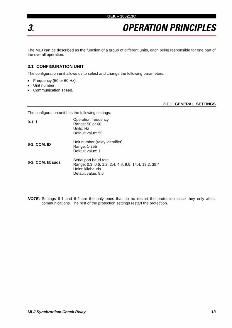
The configuration unit has the following settings:
0-1: f Operation frequency Range: 50 or 60 Units: Hz Default value: 50
6-1: COM. ID Unit number (relay identifier) Range: 1-255 Default value: 1
6-2: COM. kbauds Serial port baud rate Range: 0.3, 0.6, 1.2, 2.4, 4.8, 9.6, 14.4, 19.2, 38.4 Units: kilobauds Default value: 9.6
NOTE: Settings 6-1 and 6-2 are the only ones that do no restart the protection since they only affect communications. The rest of the protection settings restart the protection.

GEK – 106213C
14 MLJ Synchronism Check Relay
3.2 SYNCHRONISM CHECK UNIT
The main function of the MLJ is that of providing synchronism conditions for circuit breaker closures. The synchronism check unit analyses the voltage magnitudes at both side of the circuit breaker, and the status of inputs and the settings, giving a synchronism signal if the conditions are met.
Depending on the status of the Manual input, this unit has two modes of operation: Manual mode and Continuous mode. They are both described below.
3.2.1 MODE OF OPERATION
Using an analogue to digital converter, samples of line and bus voltages are acquired. From the samples, and applying the discrete Fourier transform (DFT), the module and argument of both magnitudes are obtained, and from them, the voltage and angle differences. With the measurement of the period, the frequency slip is obtained.
Once the basic fundamental magnitudes and their derivatives have been obtained, they are compared to the settings (see figure 7). The status of the external digital inputs is checked as well: circuit breaker 52b input, Manual mode input and Enable input. For the checking to begin, input 52b must be activated, showing that the circuit breaker is open.
If all the synchronism conditions are met, a time delay mechanism will be tripped and when the time limit is reached the synchronism signal SYNC will finally be obtained.
There are two different settings for the time delay mechanism:
• If Manual input is not activated, it will remain in Continuous mode and the time delay mechanism will work based on the first setting (setting 1-4 t cont). If, on the other hand, Manual input is activated, it will work in Manual mode and the setting of the time delay mechanism will be the second setting (setting 1-5 t man).
• If the relay is in Manual mode, checking synchronism will begin when the Enable input is activated.
However, in Continuous mode, the Enable input will not effect the relay.
The synchronism signal can be obtained in the Enable and Closure output relays, as well as in the auxiliary relays, if they have been configured for this purpose.
3.2.2 SETTINGS
The synchronism unit is assigned the following settings:
1-1: ΔV: Voltage difference (absolute value).
Range: from 2 to 90 in steps of 0.5 Units: volts Default value: 15
1-2: Δθ:
Angle Range: from 2 to 60º in steps of 1 Units: degrees Default value: 10
1-3: Δf; Difference in frequencies (frequency slip). Range: from 10 to 500 in steps of 10 Units: mHz Default value: 20
1-4:t cont: Time delay in continuous mode. Range: from 0.1 to 99.0 steps of 0.1 Units: seconds

GEK – 106213C
MLJ Synchronism Check Relay 15
Default value: 0.1
1-5: t man: Time delay in manual mode. Range: from 0.1 to 99.0 steps of 0.1 Units: seconds Default value: 10.0
2-1: SUP 27 ON-OFF: Undervoltage supervision enable Range: Enabled or disabled Units: -- Default value: OFF (Disabled)
2-2: SUP 27 V: Undervoltage threshold supervision. Range: from 10 to 180 in steps of 1 Units: volts Default value: 40
4-1: 25 ON-OFF: Activation of the synchronism check unit. Range: Enabled or disabled Units: -- Default value: OFF (Disabled)
3.2.3 FAILURE OF CLOSURE CONDITIONS
In order to make possible certain applications, the MLJ can provide a signal indicating Synchronism Failure if synchronism conditions have not been achieved 1 minute from having activated the Enable input when the Manual mode input is set (applying positive to the B4 terminal).
This signal showing a failure in closure conditions may be obtained via a suitable configuration of the auxiliary contacts. This unit does not have its own setting.

GEK – 106213C
16 MLJ Synchronism Check Relay
3.3 UNDERVOLTAGE UNIT Besides the undervoltage described in and linked with the synchronism unit, there is an independent unit which has various undervoltage and overvoltage functions to allow for the closure of the circuit breaker in dead lines and/or bus situations (see figure 1).
3.3.1 MODE OF OPERATION
The modulus are calculated from the line and bus voltage phasors and then compared with the settings. For each voltage two different levels can be set.
If the voltage is below the set undervoltage level, the corresponding line or bus is said to be dead. If the voltage is above the set overvoltage level, the line or bus is said to be live.
There can be three different situations of undervoltage: dead line and bus (DLDB), dead line and live bus (DLLB), or dead bus and live line (LLDB). By choosing settings we are able to make the undervoltage unit operate in any of these situations.
Similar to what has been stated in the case of the synchronism unit, if the Manual input is activated, in order for the undervoltage units to operate, it is necessary to also activate the Enable input. However, as opposed to the synchronism check unit, this undervoltage unit has no time delay whatsoever.
3.3.2 SETTINGS
The undervoltage unit has the following assigned settings:
3-1: VL↑: Level of voltage present in line (live line: LL). Range: from 40 to 245 in steps of 1. Units: volts Default value: 50
3-2: VL↓: Level of voltage absent in line (dead line: DL). Range: from 10 to 180 in steps of 1. Units: volts Default value: 30
3-3: VB↑: Level of voltage present in bus (live bus: LB). Range: from 40 to 245 in steps of 1. Units: volts Default value: 50
3-4: VB↓: Level of voltage absent in bus (dead bus: DB). Range: from 10 to 180 in steps of 1. Units: volts Default value: 30
4-2: DLDB ON-OFF: Activation condition: dead line and bus (DLDB). Range: Enabled or disabled. Units: -- Default value: OFF (Disabled)
4-3: DLLB ON-OFF: Activation condition: dead line with live bus (DLLB). Range: Enabled or disabled. Units: -- Default value: OFF (Disabled)
4-4: LLDB ON-OFF: Activation condition: live line with dead bus (LLDB). Range: Enabled or disabled. Units: -- Default value: OFF (Disabled)

GEK – 106213C
MLJ Synchronism Check Relay 17
NOTE: The relay does not check to see if the live line setting (3-1) is greater than the dead line setting (3-2). This is also applied to the bus settings (3-3 and 3-4). This allows for protection schemes for under or overvoltage, as well as inhibiting close enable in overvoltage situations.

GEK – 106213C
18 MLJ Synchronism Check Relay
3.4 INPUT UNITS
The three digital inputs are activated with D.C. voltages and with the same range of values as those of the auxiliary voltage.
The input unit not only reads the state of the inputs, but also filters the possible bounce or noise which may be present.
Input 52b indicates the state of the circuit breaker. If it is active it means that the circuit breaker is open. In this case the synchronism unit can give synchronism if the rest of the set conditions are met. If it is not used, voltage must be applied to this input in order to enable the synchronism unit.
The Manual mode input changes the time of the delay mechanism of the synchronism unit and gives way to the Enable input; if that input is not active, neither the synchronism nor the undervoltage will be activated.
When Manual mode is not desired, simply disconnect the Manual and Enable inputs, leaving the terminals corresponding to these two inputs free.

GEK – 106213C
MLJ Synchronism Check Relay 19
3.5 SELF-CHECK UNIT
While operating the synchronism and undervoltage units, the MLJ continuously carries out internal checks to verify the integrity of its components.
3.5.1 MODE OF OPERATION
During start-ups and regular operation, the MLJ monitors the following parameters without interfering with normal operation:
• Program memory (ROM). • Work memory (RAM). • Non-volatile setting memory (EEPROM). • Setting validity. • Analog measurement circuits.
A WATCHDOG internal system diagnosis the program sequences using task chaining - which provides a high level of security of the internal operation.
During start-up, a thorough check is carried out, during which the message “tSt” appears on the relay display.
This unit indicates possible failures detected using codes on the display. It also generates an Alarm signal, which can be obtained on an alarm contact (programmable) as well as an auxiliary contact.
Upon detection of a system failure, the outputs are deactivated in order to avoid misoperation of the relay.
The codes for failures are:
0.0. No defects 8.0. ROM failure. The program memory has failed. 8.1. Writing failure to EEPROM 8.2. RAM program failure 0.1. Setting failure. The settings stored are incorrect. This error is also shown when the EEPROM
memory is new (in which case the settings are stored by default). 0.4. Measurement error (defect in the analog circuits).
If there are multiple failures, only the one with top priority is shown. The above is listed from most to least important.

GEK – 106213C
20 MLJ Synchronism Check Relay
3.6 OUTPUT UNITS
The MLJ has 5 outputs which are relay contacts. The contacts can be configured as normally opened (N.O.) or normally closed (N.C.), by means of internal jumpers (welded in the printed circuit board). The contacts included are:
2 close enable contacts. Set in the factory as normally opened (N.O.) (non-configurable). 1 alarm contact. Set in the factory as normally closed (N.C.) (non-configurable). 1 auxiliary contact. Set in the factory as normally opened (N.O.) and configured in factory as function 25. 1 auxiliary contact. Set in the factory as normally opened (N.O.) and configured in factory as function 27.
3.6.1 MODE OF OPERATION
Internally, the MLJ reads the signals sent from the following units: the synchronism and synchronism failure signals supplied by the synchronism unit; the undervoltage, dead bus and line signals supplied by the undervoltage unit; and, finally, the alarm signal given by the self-check unit.
If there is a synchronism or undervoltage signal, this unit will activate the Close enable relays.
If there is an Alarm signal, or if the power fails, the Alarm relay will be deactivated. For this reason this contact is always configured as normally closed (N.C.) contact.
The auxiliary relays are activated depending on how they have previously been configured. The configuration is individual for each of them, and is done by selection using the following menu:
− Close enable (PEr) − Synchronism (25) − Undervoltage (27) − Dead line (_dL) − Dead bus (db_) − Failure of closure conditions (F25) − Alarm (ALA)
NOTE: the message that appears on the screen is shown in parenthesis.
The selection of the outputs as normally opened (N.O.) or normally closed (N.C.) can be done withdrawing the MLJ from its case and changing the jumpers to C for closed and A for opened, respectively (a solder gun is required for this operation).
3.6.2 SETTINGS
There are two settings, one for each of the auxiliary outputs:
5-1 ┤├ 1: Configuration: first auxiliary output Range: PEr, 25, 27, _dL, db_, F25, ALA Units: --
Default value: 25 (synchronism)
5-2 ┤├ 2: Configuration: second auxiliary output Range: PEr, 25, 27, _dL, db_, F25, ALA Units: -- Default value: 27 (undervoltage)

GEK – 106213C
MLJ Synchronism Check Relay 21
3.7 POWER SUPPLY
The power supply circuit of the MLJ generates, from the auxiliary voltage, the internal voltages necessary for the operation of the relay.
The power supply isolates the internal circuitry from external perturbations, for both industrial and high frequencies.
The power supply is effective over a wide range and is a switching type power supply.

GEK – 106213C
22 MLJ Synchronism Check Relay

GEK – 106213C
MLJ Synchronism Check Relay 23
4. TECHNICAL CHARACTERISTICS
4.1 MODEL LIST
Here is the information required to completely define the MLJ models. (See chart below):
MLJ 1 0 0 * B 0 1 0 * 0 0 * DESCRIPTION
Communications
5 RS-485
6 RS-485, 232, Plastic Optical Fibre
7 RS-485, 232, Glass Optical Fibre
Auxiliary and Inputs Voltage
F 24-48 VDC
G 48-125 VDC
H 110-250 VDC
Case
C Individual Case
S In MID system

GEK – 106213C
24 MLJ Synchronism Check Relay
4.2 TECHNICAL CHARACTERISTICS
• FREQUENCY
50 or 60 Hz, programmable by user.
• RATED VOLTAGE
63 to 220 Vac.
• AUXILIARY POWER
24 - 48 Vdc ± 20%
48 – 125 Vdc ± 20%
110 - 250 Vdc ± 20%
• MAXIMUM VOLTAGE ALLOWABLE
Continuous: 440 Vac.
• TEMPERATURE RANGES
Operating: -25ºC to +55ºC
Storage: -40ºC to +70ºC
Comply with IEC standard 255-6 (for the -25º to +55ºC interval) and ANSI C37.90 (specifying the -25º to +55ºC interval).
• AMBIENT HUMIDITY
Up to 95% without condensation.
• CLOSURE ENABLE CONTACTS
Break capacity: 4000 VA
Maximum continuous voltage: 300 Vdc
Maximum alternating voltage: 440 Vac
Carry continuously: 16 A
Make and carry: 30 A
• ALARM AND AUXILIARY CONTACTS
Break: 1760 VA
Maximum continuous voltage: 250 Vdc
Maximum alternating voltage: 380 Vac
Make and carry: 8 A
Carry continuously: 8 A
• ACCURACY
Voltage: 2% or 0.5 V
Voltage difference: 3% or 1 V
Angle difference: 1º (voltages between 20 and 220 Vac)
2.5º (voltages between 10 and 20 Vac and between 220 and 300 Vac)
Frequency slip: 5 mHz (range of 45 to 65 Hz)

GEK – 106213C
MLJ Synchronism Check Relay 25
Time: 1% or 30 ms (*)
The slip measurement unit may require up to 60 ms, which will be added to the time delay introduced by setting; this is typical behaviour.
• VOLTAGE CIRCUIT BURDEN
Less than 0.15 VA at 110 V and 50 Hz or at 120 V and 60 Hz.
• DIGITAL INPUTS BURDEN
24 to 48 Vdc model: 30 kOhm
110 to 220 Vdc model: 136 kOhm
• AUXILIARY POWER SUPPLY BURDEN
Idle: 3W (NC alarm relay activated only)
Tripped: 6W (all relays activated)
• WEIGHTS
Net: 3 kg.
Shipping: 4 kg.
GEK – 106213C
26 MLJ Synchronism Check Relay
4.3 INSULATION According to IEC 255-5.
Between each terminal and ground: 2000 Vac for 1 minute at industrial frequency.
Between independent circuits: 2000 Vac for 1 minute at industrial frequency.
4.4 TYPE TESTS
1 Mhz noise test
2.5 kV, 1 kV peak, class III according to IEC 255-4.
Impulse test
5 kV peak, 1.2/50 μs, 0.5 J according to IEC 255-4.
Electrostatic discharge
According to IEC 1000-1-2, IEC 255-22-2 class IV.
Radio interference
According to IEC 1000-1-3, IEC 255-22-3 class III.
Fast transients
According to IEC 1000-1-4, IEC 255-22-4 class IV.
Radiofrequency emission (radiated interference)
According to EN 55022, class B.
Magnetic fields
According to IEC 100-4-8, class V.
Sinusoidal vibrations
According to IEC 255-21-1, class II.
Shock test
According to IEC 255-21-2, class II.
The MLJ relay complies with these regulations, which include the GE standard of insulation and electromagnetic compatibility and the standards required for the Community Standard 89/336 for the European Community CE label, under the harmonised European regulations. It also complies with the European directive requirements for low voltage, and the environmental and operative requirements established in regulations ANSI C37.90, IEC 255-5, IEC 255-6 and IEC 68.

GEK – 106213C
MLJ Synchronism Check Relay 27
5. HARDWARE DESCRIPTION
5.1 CASE The case of the MLJ is made of steel plate, with an anti-corrosion treatment and painted with epoxy powder paint. The standard dimensions are shown in figure 3.
The front cover is made of a transparent plastic material fitted tightly to the case, forming a seal that prevents dust from entering and protects it from any accidental tampering. Included is a switch which allows access to the ENTER button without having to remove the cover. With this button the readout menu can be accessed allowing viewing of all the parameters indicated on the characteristic plate under the title DISPLAY.
The relay can be withdrawn completely from its case without having to disconnect any wires. Nevertheless, it is advisable to disconnect the voltage of the auxiliary feed before removing the relay, though it is not mandatory.
5.2 INTERNAL CONNECTIONS External wiring is carried out in the two terminal blocks mounted in the rear part of the case. Each terminal block contains 12 terminals with screws M3 (metric 3 mm diameter) (see figure 4).
There is no internal wiring, given that the relay is made up of a removable card with a connector designed for directed insertion into the terminal blocks.
5.3 IDENTIFICATION The complete relay model is indicated on the nameplate. (See figure 2).
The terminal blocks are identified by a letter located on the back plate, just above the left edge (looking at the relay from the back) of each block. There are two terminal blocks in each case, each identified by a letter: A or B.
In each terminal block, the terminals are labelled from 1 to 12.
5.4 MLJ FRONT DEVICES The following setting and signalling elements are located on the front plate of the MLJ:
Control pushbuttons
The MLJ comes with three push buttons to control all of the relay operations.
ENTER ↵
PLUS +
MINUS –

GEK – 106213C
28 MLJ Synchronism Check Relay
Displays
Three red seven segment displays (LED type) are used to supply information to the user and to make it easier to set the relay.
LEDs
In addition to the displays described above, there are three LEDs which provide the following information:
• READY: green LED. Relay available and protection enabled. • 52: Red LED indicating close enable condition. • 27: Red LED indicating undervoltage condition.

GEK – 106213C
MLJ Synchronism Check Relay 29
6. OPERATION OF MLJ (KEYPAD AND DISPLAY)
The MLJ is operated by means of three push-buttons located on the front. These buttons are lined up vertically and, from top to bottom; they are “ENTER”, “+”, and “-”.
The first button is indicated with an arrow (see figure 2), although throughout this manual it is referred to as ENTER. With the cover on, only this button can be accessed using a push button.
The relay supplies information by means of three displays of seven segments and using three LEDs, all of which are located on the front. The LEDs are lined up vertically and are marked, from top to bottom: “READY”, “52”, and “27”.
The MLJ can be set in one of the three following conditions:
• Readout Sequence: supplies information about the state of the relay, voltage values, frequency slip, registers of the last close enable, etc. To operate, simply push the ENTER button.
• Setting Sequence: allows consulting and changing of the operation settings of the MLJ. All three buttons
are used for this operation. • Calibration Sequence: this function gives the average of the line and bus voltages, to assist in
calibration.
Immediately after connecting the relay, it carries out a self-check test and the letters tSt appear. Upon completion of the self-check test, the relay becomes operative, in Readout Sequence, with the state of the line and bus shown on the display (live or dead).
CALIBRATIONS READINGS SETTINGS
Going from one sequence to another isdone by pressing either one button orsimultaneously pressing a combinationof buttons. As can be seen in thediagram, if no button is pressed for twominutes while in Setting Sequence, itwill return automatically to ReadoutSequence. minutes

GEK – 106213C
30 MLJ Synchronism Check Relay
6.1 READOUT SEQUENCE This is the typical sequence for the MLJ as well as the power-up sequence. It is divided into a series of “Functions”, each corresponding to different types of information. These functions are numbered from 1 to 12 and are identified by the letter F followed by the number of the function.
In normal operation, and shortly after being connected, the MLJ displays the state of the line and bus. The left-hand segment represents the state of the line and the right-hand segment, the state of the bus. If both are live, two horizontal upper segments will light up. This is the reading assigned to the last function, F12.
If the ENTER button is now pressed and held down, F0 will appear.
While the button is pressed, this code will remain on the display. It tells us that we are in Function 0 of the Readout Sequence. This function, which will appear as soon as the button is released, indicates the Status of the relay.
If the ENTER button is pressed a second time, the second function, F1 will appear. This function shows the value of
the line voltage, and will be seen as soon as the ENTER button is released.
In this fashion, pressing and releasing the ENTER button, we can go through the entire Readout Sequence. On the front of the relay, under the word “DISPLAY” there is a list of all of the functions. They are listed below:
F0: STATUS State of relay
F1: VL Line voltage
F2: VB Bus voltage
F3: ΔV Voltage difference
F4: Δθ Phase angle
F5: Δf Frequency slip
F6: LAST VL VL in the last close enable
F7: LAST VB VB in the last close enable
F8: LAST ΔV ΔV in the last close enable
F9: LAST Δθ Δθ in the last close enable
F10: LAST Δf Δf in the last close enable
F11: TEST Display test, LEDs and inputs
F12: VL VB State of line and bus
Each of these functions is covered in further detail.
ENT

GEK – 106213C
MLJ Synchronism Check Relay 31
6.1.1 F0: STATE OF RELAY, ERROR CODES
The state of the MLJ presented by a two-digit code. The decimal points remain lit so as to distinguish the code from other readings. A 00 code (everything correct) would be represented as follows:
The state codes for the MLJ, in order of priority, are:
0.0. No defects 8.0. ROM failure. The program memory has failed. 8.1. Failure in writing to EEPROM 8.2. RAM program failure 0.1. Setting failure. The settings stored are incorrect. This error is also produced when the EEPROM
memory is new (in which case the default settings are stored). 0.4. Measurement error (defect in the analog circuits).
The error 0.1. can be corrected by the user by simply modifying the value of any of the settings.
The rest of the errors indicate an electronic failure; if such errors are persistent, maintenance will be required. If the error is transitory and disappears, the MLJ will reset and start up in the normal fashion.
6.1.2 F1, F2: VL, VB, VOLTAGE IN LINE AND BARS
These readings supply the RMS values of voltages in real time.
6.1.3 F3:ΔV VOLTAGE DIFFERENCE
The relay subtracts the line and bus voltages; the absolute value of the subtraction is what is represented in this reading. See the graphic of phasors in the APPLICATION section.
6.1.4 F4: Δθ PHASE ANGLE
The phase angle is always given in absolute values which fall between 0 and 180º. The angle measurement is not influenced significantly by variations in voltage.
If the line or bus voltage is less than 9 volts, since the relay does not consider the angle measurements precise enough in such conditions, three horizontal lines will appear on the screen (overflow indicator).
6.1.5 F5: ΔF FREQUENCY SLIP
This reading supplies the frequency slip in mHz, calculated based on the difference in frequencies.
For the same reason mentioned in the previous section, if voltage is less than 9 volts, three horizontal lines will appear on the screen.

GEK – 106213C
32 MLJ Synchronism Check Relay
6.1.6 F6, F7, F8, F9, AND F10 MAGNITUDE RECORDS
When close enable is given, whether by synchronism or undervoltage, the relay registers of certain measured magnitudes at that moment. Later, when so desired, in the Reading Sequence they can be viewed with the following functions:
F6: LAST VL F7: LAST VB F8: LAST ΔV F9: LAST Δθ F10: LAST Δf
6.1.7 F11: TEST, DISPLAY AND INPUTS TEST
In this reading, all the segments of the displays will light up and blink in order to make sure there that none is defective.
The three LEDs will also light up, indicating they are not defective.
Additionally, the LEDs act as a control for the digital inputs. If these are active the LEDs will blink on and off; if they are not active, they will light up continuously. The are assigned the follows codes:
• MANUAL input → LED READY • ENABLE input → LED 52 • INPUT 52b → LED 27
6.1.8 F12: VL VB LINE AND BUSBARS STATUS
Through the horizontal segments of the display, the MLJ relay gives an indication as to whether the line (left-hand display) or the bus (right-hand display) are live or dead.
The upper segments indicate live; the lower, dead, and the middle segments show that the value of the voltage falls between the live and dead values. These limits are determined by the settings in 3-1 to 3-4.
The MLJ admits the live limit to be inferior to the dead limit. In these cases both the upper as well as the lower segments can be lit up.

GEK – 106213C
MLJ Synchronism Check Relay 33
6.2 SEQUENCE OF SETTINGS In order to introduce or modify the settings it is necessary for the relay to be in the Setting Sequence. To do this the protective cover must be removed as the three buttons will be used.
Supposing we are in the Readout Sequence. In order to enter in the Setting Sequence, the ENTER button must be pressed and, without releasing it, press the “-” button. After this operation has been done, (the buttons may be released), 1-1 will appear on the screen. This means that the 1-1 setting (voltage difference) can be changed.
Inversely, if you want to go back to the Readout Sequence from the Setting Sequence, both the “+” and the “-” buttons must be pressed simultaneously. In any case, if two minutes were to pass without any button being pressed, the MLJ will go automatically back to the Readout Sequence.
Let us suppose we are in the Setting Sequence. In this case the following can be done:
• Go to the next setting (1-2). Press the “+” button. • Go to the previous setting (0-1). Press the “-” button. • See or change the current setting (1-2). Press ENTER.
In the first two situations we can go forward or backward throughout the entire list of settings by simply pressing the “+” or the “-” button. On the nameplate, under the word “SETTINGS” a complete list can be found.
If on the other hand, ENTER is pressed, the value of the setting will be seen blinking; if ENTER is pressed again the setting will be left as it was and on the screen the name of the current setting will appear, for example 1-1.
If instead of having pressed the last ENTER, the “+” or the “-” button had been pressed, the setting would have been modified, either increasing or decreasing it by one step. This modification does not take place until it has been confirmed with an ENTER. At that moment the setting is stored in the non-volatile memory and protection with the new functioning parameters is started up.
In the BEGINNING OPERATION chapter of this book all of the operation units, settings, ranges, stages and units are described.
Here is an example:
Let us suppose that in setting 1-3 (frequency slip) we have 20 mHz and we wish to change it to 70 mHz.
• We begin with the Readout Sequence display, which gives us the line and bus activity, and go to the Setting Sequence:
Display: - - Press: ENTER (F0) appears on the display. Without releasing it press “-”) Display: 1-1 (the buttons can now be released)
• We now go to the setting 1-3:
Press: “+” Display: 1-2 Press: “+” Display: 1-3 (we have achieved the desired setting)
• Now we will modify it:
Press: ENTER Display: 20 - blinking (these are the current 20 mHz) Press: “+” (press 5 times since the pitch is 10) Display: 70 - blinking (we now have the desires setting) Press: ENTER (the change has been carried out) Display: 1-3

GEK – 106213C
34 MLJ Synchronism Check Relay
In brief, the process is the same for any desired setting modification: select the code for the desired setting modification, press ENTER, change it by pressing either “+” or “-”, and confirm the change with ENTER.
If when the setting is being changed, the “+” or “-” button is held constantly, acceleration will occur, speeding up the change in setting.
If the maximum allowed value for the setting appears on the display, pressing “+” will have no effect. The same will happen if the minimum allowed value appears on the display and “-” is pressed.
NOTE: a change in settings causes all the units to restart; if there is an output activated, is will be deactivated until the corresponding unit renews the activation.
GEK – 106213C
MLJ Synchronism Check Relay 35
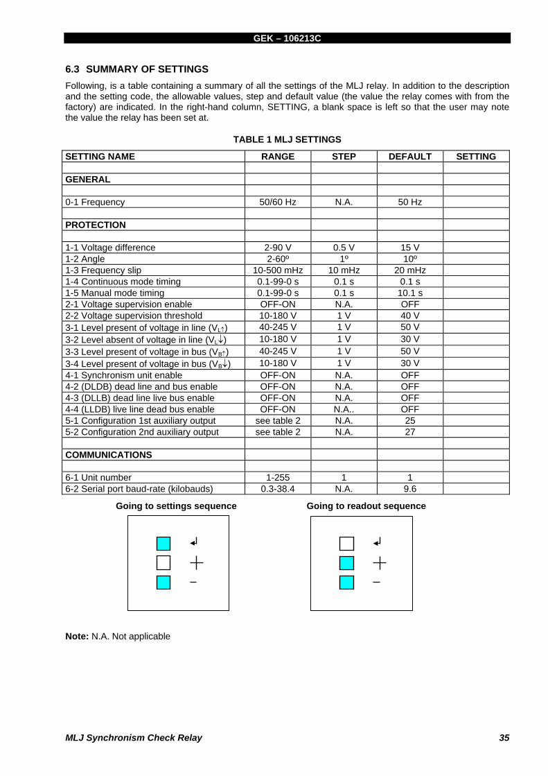
6.3 SUMMARY OF SETTINGS Following, is a table containing a summary of all the settings of the MLJ relay. In addition to the description and the setting code, the allowable values, step and default value (the value the relay comes with from the factory) are indicated. In the right-hand column, SETTING, a blank space is left so that the user may note the value the relay has been set at.
TABLE 1 MLJ SETTINGS
SETTING NAME RANGE STEP DEFAULT SETTING GENERAL 0-1 Frequency 50/60 Hz N.A. 50 Hz PROTECTION 1-1 Voltage difference 2-90 V 0.5 V 15 V 1-2 Angle 2-60º 1º 10º 1-3 Frequency slip 10-500 mHz 10 mHz 20 mHz 1-4 Continuous mode timing 0.1-99-0 s 0.1 s 0.1 s 1-5 Manual mode timing 0.1-99-0 s 0.1 s 10.1 s 2-1 Voltage supervision enable OFF-ON N.A. OFF 2-2 Voltage supervision threshold 10-180 V 1 V 40 V 3-1 Level present of voltage in line (VL↑) 40-245 V 1 V 50 V 3-2 Level absent of voltage in line (VL↓) 10-180 V 1 V 30 V 3-3 Level present of voltage in bus (VB↑) 40-245 V 1 V 50 V 3-4 Level present of voltage in bus (VB↓) 10-180 V 1 V 30 V 4-1 Synchronism unit enable OFF-ON N.A. OFF 4-2 (DLDB) dead line and bus enable OFF-ON N.A. OFF 4-3 (DLLB) dead line live bus enable OFF-ON N.A. OFF 4-4 (LLDB) live line dead bus enable OFF-ON N.A.. OFF 5-1 Configuration 1st auxiliary output see table 2 N.A. 25 5-2 Configuration 2nd auxiliary output see table 2 N.A. 27 COMMUNICATIONS 6-1 Unit number 1-255 1 1 6-2 Serial port baud-rate (kilobauds) 0.3-38.4 N.A. 9.6
Going to settings sequence Going to readout sequence
Note: N.A. Not applicable

GEK – 106213C
36 MLJ Synchronism Check Relay
TABLE 2 CONFIGURATION OF OUTPUTS
FUNCTION NAME FUNCTION OPERATION PEr Close enable 25 Synchronism 27 Undervoltage _dL Dead line db_ Dead bus F25 Fail to close ALA Alarm
If while in Readout Sequence, the ENTER and “+” buttons, are pressed simultaneously, the word CAL will appear briefly on the screen, followed immediately by the average value of the line and bus voltages.
By applying a known voltage, for example 60 RMS, to both the line and bus inputs, the trimmer is adjusted (see figure 5) until a reading of 60.0 on the display is obtained.
If we now press the ENTER button for a moment, we return to Readout Sequence.

GEK – 106213C
MLJ Synchronism Check Relay 37
7. ACCEPTANCE TESTS
7.1 INTRODUCTION Given the digital nature of this relay, in most occasions making sure that the relay measures correctly will guarantee proper performance, since all of the logic of measurement and protection is implemented by means of programming. In order to do this, the voltages in the line and bus need only to be measured with a multimeter and make sure they coincide, within the specified accuracy, with the reading indicated on the screen.
A phasemeter should be used in order to check the correct measurement of the voltage and phase difference (since the voltage difference is measured by vectors) if angle and voltage is required to be tested.
Finally, with an accurate and stable frequency meter the line and bus voltage frequency can be measured the difference between them calculated, which should coincide with the measurement that appears on the relay screen.
7.2 VISUAL INSPECTION Check the nameplate stamping to ensure that the model number and rating of the relay agree with the requisition. The relay should also be checked for scratches, dents, or loose components that may have been caused from negligent transport.
7.3 INSULATION Due to the presence of capacitors for immunising the relay from external interference, during the insulation test, approximately 7 mA for each capacitor is consumed. In the event that the apparatus used to carry out the insulation test does not permit such a consumption, the test will be done by grouping less terminals.
These tests are only carried out on new relays. A new relay means one that has not been in service, whose expedition date is not more than a year old, and one which has been stored in suitable conditions so as to prevent any deterioration.
NOTE: It is very important that the strip connected to the ground terminal on the back of the relay is tightened at all time. If this strip is loose, harmful transients could occur when the insulation test voltages are performed.
Short-circuit all the terminals except A11, A12, B11 and B12. Slowly apply 2000 V of alternating current to the chassis and then slowly reduce it back down to 0 V.
7.4 SYNCHRONISM UNIT For these tests, two independent voltage generators, adjustable in amplitude and phase, should be available.
In order to carry out these tests the synchronism unit should be activated and the undervoltage unit deactivated. This is done by putting the 4-1 setting on ON and settings 4-2, 4-3 and 4-4 on OFF.
Due to the complexity of the necessary equipment, it is not recommended to carry out the frequency difference test. To check that the measurement is correct, the slip on the readout menu (readout F5) is visualized by applying a voltage greater than 10 V to the line and the buses. The readout should be 0 mHz.

GEK – 106213C
38 MLJ Synchronism Check Relay
7.4.1 VOLTAGE UNIT TEST
The setting by default is used for the voltage difference; In this case 15 V.
Apply continuous voltage to input 52b (simulates open circuit breaker).
The Close enable contact should be closed and the red LED 52 lit up.
Reduce the voltage in the buses until the relay drops. At 44 V this drop should clearly occur, at which time the voltage difference is 16 V (60 V - 44 V = 16 V), which is greater than the 15V of the setting.
When two independent supplies are not available, it is recommended to use a variable autotransformer in order to be able to charge the bus voltage when so desired. If only voltages other than 60 V (63.5 V or 110 V for example) are available, the test can also be done although keeping in mind that the relay will trip when the voltage difference is less than the set value.
If a variable autotransformer is not available this unit can be tested by applying, for instance, 220 V to the line and 127 V to the bus by means of a simple 220/127 V transformer. In this case, Close enable will not be given, given that the voltage difference is very large. In order to generate Close enable, the same voltage (220 V for example) is simply applied to the line and bus inputs.
7.4.2 ANGLE UNIT TEST
For the angle difference, the default setting of 15º should be kept.
Apply continuous voltage to input 52b (simulates open circuit breaker).
Apply 60 V to the line and bus inputs (these should be in phase).
The Close enable contacts should be closed and the red LED 52 (Close enable) lit up.
Lag the bus voltage until the relay drops. This drop should clearly occur at 17º, greater than the set 15º.
When two independent supplies are not available, the test is done by reversing the polarity of the bus voltages, which means lagging it to 180º, and in which case the relay will not trip.
7.5 UNDERVOLTAGE UNIT
In order to carry out these tests the undervoltage unit should be enabled and the synchronism unit disabled. This is done by putting setting 4-1 on OFF, setting 4-2 on ON and settings 4-3 and 4-4 on OFF.
Apply 40 V both to line and bus. The middle segments corresponding to the line and bars will light up on the relay screen when the relay is in readout in the idle position.
The relay should not trip.
Reduce the voltage to 20 V. The lower segments on the screen will be activated. The relay should operate and the red LEDs 52 (Close enable) and 27 (undervoltage) lit up.
If there is no variable power supply available, the test can be done by applying and removing a known voltage (for example 63 V).

GEK – 106213C
MLJ Synchronism Check Relay 39
7.6 CONTINUOUS AND MANUAL MODE TESTS
With the default settings, the delay in continuous mode is 0.1 s and in manual mode it is 10 s. This helps to know when the relay acts in one mode or the other.
Manual mode
Apply continuous voltage to inputs MANUAL, ENABLE and 52b.
Apply 60 V in parallel to line and buses.
When approximately 10 seconds are up (plus some delay with the measurement units and output relays, which in any case, is less than 100 ms) the relay should function.
Remove the voltage to the ENABLE or 52b input. The relay should drop.
Continuous mode
Apply continuous voltage to input 52b.
Apply 60 V in parallel to line and buses.
When approximately 100 milliseconds are up (plus some delay with the measurement units and output relays, less than 80 ms in any case) the relay should operate.
Remove the voltage to input 52b (simulates closure of the circuit breaker). The relay should drop.
7.7 CALIBRATION The MLJ relay is based on a microprocessor and performs numerical processing of alternating voltages, with high resolution and accuracy. It uses an algorithm that is highly unaffected by distortion to measure the RMS value. Due to minimal usage of components and the reliability of the measurement, it not considered necessary to recalibrate the relay.
7.8 GROUNDING The MLJ has a terminal (B12) for grounding. Connected to this terminal there is also a strip that connects the terminal to the relay case. This strip improves the discharge path of interference and must always be connected; it must not be disconnected even when an insulation test is being performed.
Grounding is done with a cable that leads directly to ground of the panel or the cabinet; it should never go through disconnecting terminals (that might become disconnected), nor should grounding between equipment be linked. Each one or each case must have its own cable which is directly connected.
In relays with communications or if a cable with a shield is used, the shield should be connected to the terminal intended for this purpose (B11), without interrupting continuity, and not connecting to the ground. However, for personal safety, and in order to divert interference to ground, it must always be connected to the ground in at least one point. Generally the most convenient place is on the side of the communications controller. By doing this, grounding the cable is achieved as well as avoiding circulation of currents through the cable which could affect the correct operation of communications.

GEK – 106213C
40 MLJ Synchronism Check Relay
There are several reasons for grounding a relay such as the MLJ:
• Personal safety. A defect in insulation could allow the relay case to come in contact with conductors that may deliver dangerous ground voltages. The differences in voltage to ground are the dangerous ones since people are touching the ground, normally through their footwear and the floor of the installation.
• Protection of the relay’s internal circuits against overvoltage. Overvoltage which can reach the relay by connections (power supply circuit, output contacts, etc.) tend to be the so-called common or longitudinal mode; that is, they are overvoltages that try to make the circuit to ground. The filters in the inside of the relay short-circuit these overvoltages, directing them to ground through the filters themselves and through grounding.
• Protection of the relay against electrostatic discharge. When a person moves towards a relay, it is
possible that he or she is charged in respect to the ground (this is highly improbably in a substation, but is more likely in an office environment) Upon touching any part of the relay, the person will produce a discharge to the relay which will make a circuit to the ground until it reaches the person’s feet. The grounding of the relay will make the discharge travel through the person and thus avoid its leaving through the interior of the equipment, which could interfere with its normal operation.
• Deviation of leakage currents. In the wiring of any electrical equipment to its case, if the case is
metallic, there is always a capacity, which is the sum of the interference capacity and the capacities required for filtering. Although the currents that can circulate through these capacities may not be dangerous for people, they are always startling and annoying, and made worse when the ground is wet or when lightweight footwear is used.
• Avoiding spurious measures. If there are sensitive, high impedance input circuits which are left
disconnected, the leakage currents mentioned in the previous paragraph can make their own circuits, giving out “ghost” measurements. Grounding keeps the measurement circuits from floating and the leakage currents from making their own circuits.
A similar case might arise in which the ground, from the perspective of the relay, is more harmful than beneficial, since the equipment with the better ground will be the one that offers a better path for any overvoltage produced in the substation. The disturbance could even come from the very ground cable and make a circuit to a ground with less potential, through the interference capacities with the panels. In any case, for personal safety the equipment cases must always be grounded.
Doubts about the grounding of equipment often arise; not grounding can in some cases be the source of problems while on the other hand, in other circumstances, unnecessary grounding can also lead to problems.
When dealing with grounding problems, it is not wise to have set ideas which reduce problems to only a few possibilities; one must be aware of what problems can arise and why they have come about. The only set rule, for safety’s sake, should be that all equipment that is meant to be grounded should have a ground connection.
One of the main reasons for the difficulty in achieving proper grounding is that the equivalent electric circuit, which is generally a cable, is different according to the frequency of the voltages applied to the ground. At industrial frequency (50 or 60 Hz), a cable functions as a very low impedance, and therefore the voltage at the ends will never reach higher values. But as the voltage is increased, the cable will be more like an inductance, with more impedance, and at higher frequencies the cable functions as a transmission line. For determined lengths of cable, the situation might arise in which one of the ends finishes in a short-circuit (which is exactly the goal in grounding), while the same circuit on the other end is exactly the opposite, that is, an open circuit.
It is helpful to remember that an industrial frequency that undergoes a significant variation in maximum value, typical in installations in failure circumstances, generates a large amount of high frequency harmonics.
At industrial frequency it has been seen that the cable presents low impedance, limiting overvoltages in its ends, but this is at the cost of leading high intensities, which can cause problems in induction or radiation, to the equipment or to adjacent equipment. This is one of the reasons why loops in the grounding wires must be avoided.

GEK – 106213C
MLJ Synchronism Check Relay 41
In conclusion, it is necessary to always keep the recommendations of the manufacturers in mind as far as safety measures are concerned.

GEK – 106213C
42 MLJ Synchronism Check Relay

GEK – 106213C
MLJ Synchronism Check Relay 43
8. FREQUENTLY ASKED QUESTIONS
8.1 FREQUENCY SLIP SIGN. Is there any way to tell the difference between the speeds of the two voltages. For example does a positive (+) sign appear when the bus voltage is faster than the line voltage and a negative (-) sign for a slower voltage? The answer is no. The slip is calculated as the absolute value of the difference in frequency between bus and line voltage. The math formula is: S = | fb - fl | where S Slip in mHz (milihertz) |x| Absolute value of x fb Bus frequency in mHz fl Line frequency in mHz There is no way to know the sign of the slip, therefore the sign does not appear neither in the relay 7 segment display, neither in the computer screen through the communications program MLJ-Mlink. The MLJ has not been designed to SYNCRONIZE a generator (therefore it does not give you the sign to regulate generator velocity) it has been design only to check synchronism.
8.2 VOLTAGE DIFFERENCE CALCULATION When the relay gives the voltage difference (between bus and line) is the voltage quantity in vector or scalar form? The answer is SCALAR form. For MLJ100*B, the voltage difference is the absolute value of the difference in MODULUS of bus voltage and line voltage. The math formula is: D = | |Vb| - |Vl | where D Voltage difference in V (Volts) __ Vb Bus voltage vector in V __ |Vb| Bus voltage modulus (i.e. the RMS value of bus voltage in scalar form) __ Vl Line voltage vector __ |Vl| Line voltage modulus |x| Absolute value of x The reason for using scalar difference instead of vector difference is to ease settings calculations (because settings are independent when using scalar form) and because for generator sync check applications it is recommended using scalar difference (this is related with "velocity" difference between generator and network).
GEK – 106213C
44 MLJ Synchronism Check Relay
8.3 MODBUS COMMUNICATIONS PROTOCOL Has the MLJ Synchrocheck relay an option for ModBus RTU Protocol (19200 bps)? The answer is no. The only available protocol is our GE Mlink standard. That is an open standard. Its documentation may be supplied (in English or Spanish language) if required.
8.4 PROTECTION SETTINGS Which are the recommended settings for live line and live bus? The answer is the default settings (50 Vac). If the line to neutral voltage is being used (tipically 69 V), this represents aproximately 75% of rated voltage. In case line to line voltage is applied to the equipment (120 Vac) 50 Volts are roughly 40% of rated voltage.
8.5 TESTING I am testing the relay and the close permission output relay does not close. Am I doing something wrong? A common mistake when testing this relay is to forget applying a positive to the 52b digital input to inform the relay that the breaker is open and thus, to allow close permission relay activation. A positive must be applied to terminal A5 and a negative to terminal B5 (see external connections diagram).
8.6 52B INPUT Is it mandatory wiring a 52b contact to the 52b digital input? The answer is no. Nevertheless, in order to allow synch check unit function, a positive must be applied to terminal A5 and a negative to terminal B5. In case 52b input is not being used, you should connect a wire from B1 (auxiliary dc voltage positive) to A5 (52b digital input) and a wire from B2 (auxiliary dc voltage negative) to B5 (digital inputs common). In that way, when synch check conditions are met, the output relays will be permanently energized even though the breaker is closed. The relay is able to withstand all their output relays energized permanently and will maintain its reliability.
8.7 VOLTAGE CONNECTIONS Should I connect line to neutral or line to line voltage to the bus and line voltage inputs? The answer is that both connections will work fine. The voltage inputs have been designed to measure a wide range of voltages, therefore all ranges (line to neutral or line to line) are supported as far as maximum voltage applied permanently does not exceed 440 Vac. The only consideration is that the same phase must be applied for line and bus connections (i.e. phase A) in order to allow a proper measurement of the ANGLE between line and bus voltages.

GEK – 106213C
MLJ Synchronism Check Relay 45
Figure 1 Logical diagram of Operation (226B2202H2)

GEK – 106213C
46 MLJ Synchronism Check Relay
Figure 2 Nameplate for MLJ1000/1005 models (226B1276H1)

GEK – 106213C
MLJ Synchronism Check Relay 47
4 HOLES OF 7∅ FOR MOUNTING
Figure 3 Outline and panel drilling for MLJ1000/1005 models (226B6086H1)

GEK – 106213C
48 MLJ Synchronism Check Relay
Figure 4 Rear terminal plate for MLJ1000/1005 models (226B3205H1)

GEK – 106213C
MLJ Synchronism Check Relay 49
CAUTION: DO NOT FORGET TO WIRE THE 52b INPUT (TERMINALS A5-B5) BECAUSE IF THIS CONTACT IS NOT CLOSED(MAIN BREAKER OPEN) THE RELAY WILL NOT EMIT ACLOSE ENABLE
Figure 5 External connections for MLJ1000/1005 models (226B6265H1)
Note: The transformers can be connected to phase-to-phase or phase-to-ground voltage.

GEK – 106213C
50 MLJ Synchronism Check Relay
Figure 6 Internal settings (301A7408H1)

GEK – 106213C
MLJ Synchronism Check Relay 51
Figure 7 Block Diagram (226B2201H1)

GEK – 106213C
52 MLJ Synchronism Check Relay
Figure 8. External Connections Diagram for special models “02” (B6265f2)
A B C
A1
A2
BA
RR
AS
/BU
SLI
NEA
/LIN
E
B3
A3
CBA
TENSION SIMPLELN OPTION
UB
LU
B12PE
B1 B4
CO
NT.
/MA
N.
CO
NT.
/CO
MM
AN
D
(+)
A4
PER
MIS
O
ENA
BLE
FUENTE DE
ALIMENTACION
POWER SUPPLY
CC CC
B5
(-)
A8
B8
B6
A6
A7
B7
B10
A10
A9
B9
A11 A12 B11
COM+ COM- SHIELD
RS-485
ALARMASYSTEM READY
CLOSE ENABLEPERMISO CIERRE
AUX 1
AUX 2
CLOSE ENABLEPER. CIERRE
OPCIONAL
1 PERMISO CIERRE / CLOSE ENABLE
SUBTENSION / UNDERVOLTAGE
LINEA MUERTA / DEAD LINE
BARRA MUERTA / DEAD BUS
2
3
4
5 SINCRONISMO / SYNC.
FALLO SINC/ SYNC. FAILURE6
CONFIGURACION AUXILIARESAUX CONFIGURATION
CC
52b
A5
7 ALARMA / SYSTEM READY
(*)
(*)
OPTIONAL( )
(*) Recomendada por seguridad depersonas y equipos
Persons and devices safetyrecomendation
ATENCION NO OLVIDAR CABLEAR LA ENTRADA 52b (bornas A5-B5),YA QUE SI ESTE CONTACTO NO ESTA CERRADO (INTERRUPTORPRINCIPAL ABIERTO) EL RELE NO DARA PERMISO DE CIERRE.
CAUTION: DO NOT FORGET TO WIRE THE52b INPUT (TERMINALS A5-B5)BECAUSE IF THIS CONTACT IS NOT CLOSED (MAIN BREAKEROPEN) THE RELAY WILL NOT EMIT A CLOSE ENABLE

GEK – 106213C
MLJ Synchronism Check Relay 53
Figure 9 Dimensions and Drilling for models MLJ1006 and MLJ1007 (226B6086H2).

GEK – 106213C
54 MLJ Synchronism Check Relay
Figure 10 External connections for models MLJ1006 and MLJ1007 (189C4152H1).
AB
C
A1 A2
BARRAS/BUSLINEA/LINE
B3A3
CB
A
TEN
SIO
N S
IMPL
ELN
OPT
ION
UBL
U
B12
PE
B1B4CONT./MAN.
CONT./COMMAND
(+)
A4PERMISOENABLE
FUEN
TE D
EAL
IMEN
TAC
ION
POW
ER S
UPPL
Y
CC
CC
B2B5
(-)
A8 B8B6A6 A7 B7 B10
A10
A9 B9
A11
A12
B11
COM+
COM-
SHIE
LD
RS-4
85
ALAR
MA
SYST
EM R
EAD
Y
CLO
SE E
NA
BLE
PERM
ISO
CIE
RRE
AUX
1
AUX
2
CLO
SE E
NA
BLE
PER.
CIE
RRE
OPC
ION
AL
com
o N
A o
NC
med
iant
e p
uent
esin
tern
os
'Es
tos
cont
ac
tos
pue
den
sel
ecci
ona
rse
PEr
PERM
ISO
CIE
RRE
SUBT
ENSI
ON
LIN
EA M
UERT
A
BARR
A M
UERT
A/UN
DER
VOLT
AG
E
/DEA
D L
INE
/DEA
D B
US
25 27 _dL
dB_
SYN
C F
AILU
RE
SIN
CRO
NIS
MO
FALL
O S
INC
/F2
5
/SYN
C
/CLO
SE E
NAB
LE
CO
NFI
GUR
AC
ION
AUX
ILIA
RES
AUX
CO
NFI
GU
RATIO
N
CC52b
A5
ALA
ALAR
MA
/SYS
TEM
REA
DY
(*)
(*)
OPT
ION
AL(
)
sold
ado
s.
Inte
rna
l we
lde
d ju
mp
ers
allo
wN
O o
r NC
sel
ectio
n.
(*)
Rec
om
end
ad
a p
or s
eg
urid
ad
de
pe
rson
as
y eq
uip
os.
Pers
ons
and
dev
ice
s sa
fety
reco
men
da
tion.
ATEN
CIO
N:
NO
OLV
IDAR
CA
BLEA
R LA
EN
TRAD
A 52
b
(bo
rna
s A
5-B5
),YA
QU
E SI
EST
E C
ON
TAC
TO N
O E
STA
CER
RAD
O (I
NTE
RRUP
TOR
PRIN
CIP
AL A
BIER
TO)
EL R
ELE
NO
DA
RA P
ERM
ISO
DE
CIE
RRE.
CA
UTIO
N:
DO
NO
T FO
RGET
TO W
IRE
THE
52b
INPU
T(T
ERM
INA
LS A
5-B5
)BE
CA
USE
IF T
HIS
CO
NTA
CT
ISN
OT
CLO
SED
(MAI
N B
REA
KER
OPE
N) T
HE R
ELAY
WIL
L N
OT
EMIT
A C
LOSE
EN
ABL
E.
RXTXFI
BRA
OPT
ICA
CRI
STAL
O P
LAST
ICO
67
8
SDA
SDB
SG
RS-4
85
RX-2
TX-3
GND-
5
DEL
ANTE
RO
DB-
9 FE
MA
LERS
-232
GND-
5TX
-3
RX-2
RS-2
32D
B-9
FEM
ALE
FUEN
TE D
EAL
IMEN
TAC
ION
1 3
NO
TASO
LO P
UED
E C
ON
ECTA
RSE
UNRS
-232
(+)
(-)
FIBE
R O
PTIC
GLA
SS O
R PL
AST
IC
POW
ER S
UPPL
Y
FRO
NT
1: 1:RS
-232
ON
LY O
NE
NO
TE
NO
TEEX
TERN
AL W
IRIN
G2:2:
CA
BLEA
DO
EX
TERN
ON
OTA
PORT
CAN
BE
CO
NN
ECTE
D
*N
OTA
2N
OTE
2
PUER
TO
PORT
PUER
TOTR
ASER
ORE
AR
PORT
5-G
ND
3-TX
2-RX
2-RX
3-TX
5-G
NDNO
TA 1
NO
TE 1
()
PC
)N
OTE
1N
OTA
1(
PC
MLJ
DA
C30
0
DB-
9 H
EMBR
A
DB-
9 H
EMBR
A
(DTE
)
(DC
E)
( **
)
**()
( ***
)
***
()
***
()
***
()
***
()
)( *
*

![[2020] 10 MLJ 137](https://static.fdocuments.in/doc/165x107/6181fc4baa485550ee156c32/2020-10-mlj-137.jpg)

![INTERNATIONAL CENTRE FOR THE SETTLEMENT … Intelek Timur Sdn Bhd v Future Heritage Sdn. Bhd. [2004] 1 MLJ 401 70 Klockner Industries-Anlagen GmbH v Kien Tat Sdn Bhd [1990] 3 MLJ 183](https://static.fdocuments.in/doc/165x107/5ada039c7f8b9a86378cc569/international-centre-for-the-settlement-intelek-timur-sdn-bhd-v-future-heritage.jpg)


![[2011] 6 MLJ xci Malayan Law Journal Articlesjeraldgomez.com/pdf/88501e7a7c9a417d353522d0be8ee573.pdf · 2017-04-27 · 6 MLJ xci at xcii issues such as whether these rights extend](https://static.fdocuments.in/doc/165x107/5f432a83a5df0e4196756bb0/2011-6-mlj-xci-malayan-law-journal-2017-04-27-6-mlj-xci-at-xcii-issues-such.jpg)