GDiwheelravity Defi es - Mechanical...
3
Students and researchers in the School of Mechanical Engineering at the University of Adelaide have developed a so-called diwheel that allows a driver to travel in a conventional upright position and, for the more adventurous, in an upside down position. A dSPACE MicroAutoBox was used as the development and control platform. Gravity Diwheel Defies Down Under: Australian Students developed an Upside Down Vehicle DIWHEEL PAGE 6 PAGE 7
Transcript of GDiwheelravity Defi es - Mechanical...

Students and researchers in the School ofMechanical Engineering at the University ofAdelaide have developed a so-called diwheel that allows a driver to travel in a conventional upright position and, for the more adventurous, in an upside down position. A dSPACE MicroAutoBox was used as the development and control platform.
GravityDiwheel Defi es
Down Under:
Australian Students developedan Upside Down Vehicle
DIWHEELPAGE 6 PAGE 7
Free Rotation Fun Commencing in March 2009, honors students in the School of Mechanical Engineering at the University of Ade laide designed, built and tested an electric diwheel called EDWARD (Electric Diwheel With Active Rota-tion Damping). Diwheels, like their more popular cousins the monowheel, have been around for almost one and a half
systems are almost identical, the only difference being that theframe (pendulum arm) of a diwheel is smaller than the radius of the wheels, enabling the frame tocompletely rotate without striking the ground.
Overhead Locomotion The outer wheels are driven from the inner frame and forward motion
is achieved through a reaction torque generated by the eccentric-ity of the centre of gravity of the inner frame. During operation,diwheels experience slosh (when the inner frame oscillates) and tumbling (also known as gerbiling, when the inner frame completes a revolution). This can make driving the vehicle extremely diffi cult and
“ EDWARD not only rocks (literally) but it’s green too. It’s fully electric, and employs regenerative braking, so energy is recovered when slowing down. The MicroAutoBox has saved us so much time compared to programming an embedded micro controller. Connection of all theI/O was simple and it has allowed us to rapidly try alternative control strategies. And using ControlDesk to develop the HMI was a breeze.”
Jack Parsons, Student of The University of Adelaide
centuries. A diwheel is a vehicle that consists of two large coaxial wheels that completely encompass an inner frame containing a driver (Figure 1).The inner frame, suspended between the wheels, can rotate freely. The physical arrangement of a diwheel shares many similarities with two-wheeled inverted pendulum systems such as the Segway. In fact the dynamics of the two
Control Modes
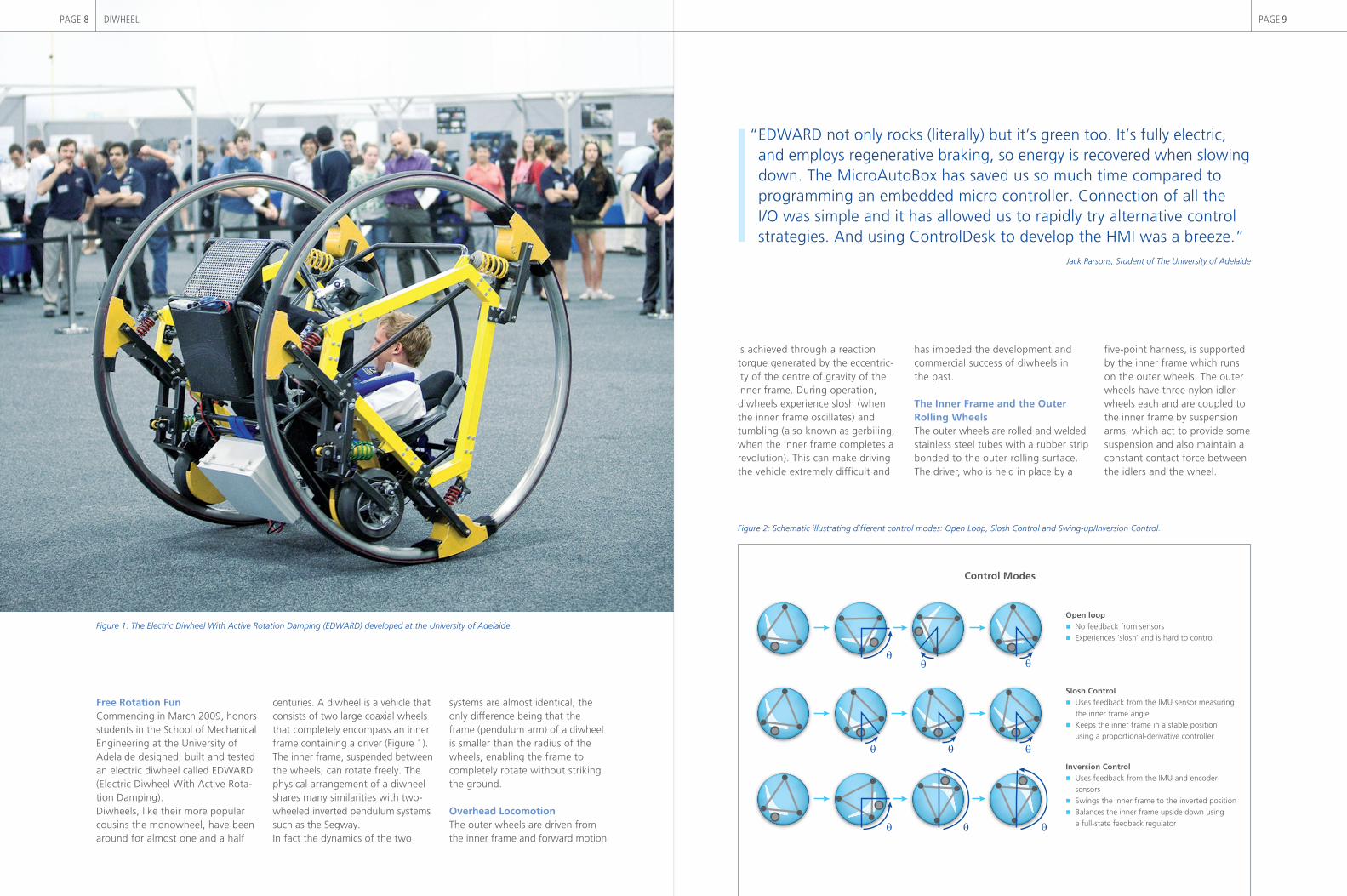
Open loop No feedback from sensors Experiences ‘slosh’ and is hard to control
Slosh Control Uses feedback from the IMU sensor measuring the inner frame angle Keeps the inner frame in a stable position using a proportional-derivative controller
Inversion Control Uses feedback from the IMU and encoder sensors Swings the inner frame to the inverted position Balances the inner frame upside down using a full-state feedback regulator
θ
θ θ
θ θ θ
θθ
θ
has impeded the development and commercial success of diwheels inthe past.
The Inner Frame and the Outer Rolling WheelsThe outer wheels are rolled and welded stainless steel tubes with a rubber strip bonded to the outer rolling surface. The driver, who is held in place by a
fi ve-point harness, is supported by the inner frame which runs on the outer wheels. The outer wheels have three nylon idler wheels each and are coupled to the inner frame by suspension arms, which act to provide some suspension and also maintain a constant contact force between the idlers and the wheel.
Figure 1: The Electric Diwheel With Active Rotation Damping (EDWARD) developed at the University of Adelaide.
Figure 2: Schematic illustrating different control modes: Open Loop, Slosh Control and Swing-up/Inversion Control.
DIWHEELPAGE 8 PAGE 9

Dr. Ben CazzolatoBen Cazzolato is Associate Professor at the University of Adelaide, teaching and researching in the fi elds of dynamics and control.
“ We often get asked why build it? Why build a roller coaster? ‘Cause it’s fun! Apart from the incredible exhilaration of driving EDWARD, there are some serious pedagogical reasons to build such a device. It teaches engi-neering students about modern system design and control techniques – the very methods they will use when working as graduate engineers.”
Dr. Ben Cazzolato, Associate Professor of The University of Adelaide
MicroAutoBox-DevelopedControl PlatformVia sprockets and chain, two 4kW brushed DC motors each drive a small motorcycle drive-wheel which contacts the inner radius of the outer wheel. Thus the vehicle can be driven forwards and backwards using a collective voltage appliedto the motors, and yaw is achieved when the motors are differentially
driven. The vehicle is drive-by-wire, with the driver controlling thevehicle via a joystick. A mechanical hand brake operates callipers on the drive-wheels for safety in case of electrical failure. There are three sensing systems onboard; an Inertial Measurement Unit (IMU) comprised of a solid state gyroscope for mea-suring pitch rate, a solid-state DC coupled accelerometer for state
The HMI: Displays information such as angle and speed to the driver, and allows for the selection of control mode
The processor: Contains software to control the diwheel Receives signals from inputs and sensors Sends signals to the motor controller which are then amplified by the motor controller to drive the motors to move the diwheel
Control System
Sensors
Input command(Joystick)
Processor
Motor controller
Electric motors
Diwheel system
Human machineinterface (HMI)
estimation of pitch angle and two incremental encoders on each of the two drive-wheels that measure the difference in angular ratebetween the inner frame and the wheels. A dSPACE Micro AutoBox provides the development and con-trol platform.A touch screen mounted in front of the driver provides feedback on the states of the vehicle (such as pitch angle, forward speed, battery charge) as well as allowing the driver to change the control modes.
From Simulation to Real-Time Control SystemThe fully-coupled differential equa-tions of a generic diwheel werederived in order to allow thedynamics of the plant and controlsystem to be simulated in MathWorks’ Simulink®. Once the control laws were developed and performed well in simulations, the controller was ported to a dSPACE MicroAutoBox via MathWorks’ Real-Time Workshop® for real-time control of the physical system.Figure 3 illustrates the signal fl ow for the functional operation of the EDWARD platform, which employs
Figure 4: Feedback control allows honors student Jack Parsons to drive around upside down.
drive-by-wire technology and control theory to aid the driver in piloting the vehicle. Such technology pre-vents the inner frame from rotating (sloshing back and forth) during operation (Figure 2), an inherent property that has limited the driv-ability of previous diwheels.And for the thrill seeker, the uniquedynamics of the vehicle can beexploited to invert the inner frame, so it is possible for the diwheel to be driven while the driver is upside down (Figure 4).
What About The Future?The driver can be orientated in any direction, and held in by a racing seat and harness, allowing for
intense accelerations of several G’s. For the fi rst time a complete mathe-matical model of a diwheel has been derived, which will enable extreme maneuvers and tricks to be per-formed at the press of a button. These tricks are to be coded in soft-ware by future honors studentsin 2011.
Dr. Ben CazzolatoThe University of Adelaide
Figure 3: Schematic illustrating the electroniccontrol system and HMI.
DIWHEELPAGE 10 PAGE 11