GCMT 13 MS CN FLR 001 1 Jun Rev.2 Flare Stack Calculation
28
FLARE STACK CALCULATION DOCUMENT NUMBER REV. CONTRACT NO. : EP37-M12LL0122D PAGE 1 of 28 GCMT-13-MS-CN-FLR-001 2 JOB NO. : 31-12008PO053 PT. PERTAMINA EP ASSET 2 PEMBELIAN & PEMASANGAN FASILITAS KOMPRESOR UNTUK GAS MUSI TIMUR FIELD PENDOPO 2 Issued for Construction 1-Jun-2015 MDY MDY HNK 1 Issued for Construction 12-May-2015 MDY MDY HNK 0 Issued for Construction 29-Apr-2015 MDY MDY HNK C Issued for Approval 10-Apr-2015 MDY MDY HNK B Issued for Approval 11-Mar-2015 MDY MDY HNK A Issued for Review 24-Feb-2015 MDY MDY HNK REV. DESCRIPTION DATE PREP'D CHK'D APV'D CHK'D APV'D PT. KOTAMINYAK INTERNUSA PT. INDOTURBINE/PT. PEP
description
Teknik mesin dan SIPIL
Transcript of GCMT 13 MS CN FLR 001 1 Jun Rev.2 Flare Stack Calculation

FLARE STACK CALCULATION
DOCUMENT NUMBER REV. CONTRACT NO. : EP37-M12LL0122D PAGE 1 of 28
GCMT-13-MS-CN-FLR-001 2 JOB NO. : 31-12008PO053
PT. PERTAMINA EP ASSET 2
PEMBELIAN & PEMASANGAN FASILITAS KOMPRESOR UNTUK GAS MUSI TIMUR
FIELD PENDOPO
2 Issued for Construction 1-Jun-2015 MDY
MDY
HNK
1 Issued for Construction 12-May-2015 MDY MDY HNK
0 Issued for Construction 29-Apr-2015 MDY MDY HNK
C Issued for Approval 10-Apr-2015 MDY MDY HNK
B Issued for Approval 11-Mar-2015 MDY MDY HNK
A Issued for Review 24-Feb-2015 MDY MDY HNK
REV. DESCRIPTION DATE PREP'D CHK'D APV'D CHK'D APV'D
PT. KOTAMINYAK INTERNUSA PT. INDOTURBINE/PT. PEP

FLARE STACK CALCULATION
DOCUMENT NUMBER REV. CONTRACT NO. : EP37-M12LL0122D Page 2 of 28 GCMT-13-MS-CN-FLR-001 2 JOB NO. : 31-12008PO053
REVISION SUMMARY
REV. DATE DESCRIPTION OF CHANGE

Comment Resolution Sheet
Document No. GCMT-13-MS-DS-FLR-001 Rev. 2
Document Title Flare Stack Calculation Date 1-Jun-15
No. Reference Description Clarification Remark &
Status
1
Check thickness diam.26” sch STD or SCH 20
Thickness diam. 26” as per request, n/a sch STD or Sch 20 For Flare Tip 26” thickness 6 mm For riser stack 26” thickness 9,52 mm

FLARE STACK CALCULATION
DOCUMENT NUMBER REV. CONTRACT NO. : EP37-M12LL0122D Page 3 of 28 GCMT-13-MS-CN-FLR-001 2 JOB NO. : 31-12008PO053
Table of Contents Page 1.0 SCOPE 4 2.0 REFERENCES 4 3.0 ANAYSIS CONDITIONS 4
3.1 Total Stack Height 4 3.2 Material Of Stack 4 3.3 Guy Wire Information 4 3.4 Deadman Information 5 3.5 Attachments at Stack 5 3.5.1 Piping 5 3.5.2 Platforms 5 3.5.3 Ladders 5 3.5.4 Flare Tip 5 3.6 Base Plate Information 5 3.7 Guy Lug Information 6 3.8 Damping Calculations 6 3.9 Deflection Limits 6 3.10 Fatigue 6 3.11 Along Wind Code : ASCE 7-05 6 3.12 Seismic Code: Uniform Building Code 1997 6 3.13 Pressure 6 3.14 External Load 7
4.0 APPLICATION SOFTWARE 7 5.0 RESULTS 7
5.1 Cable Loading (Maximum Load Summary) 7 5.2 Foundation Loading 8 5.2.1 Load Acting on Deadman Foundation 8 5.3 Guy Wire Hardware for Set # 1@ Elev 27,5 meter 9 5.4 Weight Summary 10 5.5 Wind Area Summary 10 5.6 Corroded Stack Properties 11 5.7 Summarized Worst Stresses Ratios 12 5.8 Deflection Summary 12 5.9 Stack Baseplate Summary 13 5.10 Guy Lug #1 Analysis @ 27,5 meter 14
ATTACHMENT 16

FLARE STACK CALCULATION
DOCUMENT NUMBER REV. CONTRACT NO. : EP37-M12LL0122D Page 4 of 28 GCMT-13-MS-CN-FLR-001 2 JOB NO. : 31-12008PO053
1.0 SCOPE
This report describes the result of Steel Stack Calculation for flare stack.
The purpose of a stack is to vent process exhaust gases to the atmosphere. The mechanical design of stacks is now controlled in part by air pollution rules and regulations. Heights and diameters are set by a balance between structural stability and function, while at the same time meeting the requirements for air pollution control dispersion of the gases to the atmosphere. The heights of steel stacks have increased to satisfy ambient air quality, and stack inlet gas temperatures have decreased as more heat energy is recovered. The importance of attention to stack heat losses has therefore increased. Stack minimum metal temperature should be held above the acid dew point of the vented gases, if possible. Stacks are being designed with many appurtenances to monitor the gases and make stack inspections.
2.0 REFERENCES
ASME STS-2011 Steel Stack
ASME Section IIA Material Properties
GCMT-13-MS-DB-001 Mechanical Design Basis
GCMT-13-PRO-DS-005 Process Data Sheet Flare Stack
GCMT-13-MS-DS-012 Mechanical Data Sheet For Flare Stack
3.0 ANALYSIS CONDITIONS
3.1 Total Stack Height : 32 m OUTER DIAMETERS STACK THICKNESS CORROSION ALLOWANCE Elevation Diameter Elevation Thickness Elevation Cor. Allow (m ) (mm) (m) (mm) (m) (mm) --------- -------- --------- --------- --------- ---------- 32 660,0 32,00 6,0 32,00 0,0 29 660,0 29,00 9,5 29,00 3,2
3.2 MATERIAL Of STACK: Elev Material Temp Fyld Elas Mod Alpha Allow Strs Density m Deg. C MPa MPa mm/mm/C MPa kg/m^3 ------ --------------- -------- ------- -------- ---------- ---------- ------- 32,00 310 SS 371 137,22 170998 1,74E-5 91,71 7849,0 35 206,84 195974 1,54E-5 137,90 7849,0 29,00 API-5L-B 100 220,41 196778 1,22E-5 100,66 7849,0 35 241,32 200007 1,22E-5 100,66 7849,0
3.3 GUY WIRE INFORMATION: Number of Sets of Guy Wires = 1 Each guy set consists of 3 guy wires evenly spaced 120 Deg. apart. Loads applied from 0 to 60 degrees in increments of 30 Deg, to find the worst case for the system. Installation Temperature = 35 Deg. C Elev DM # Dia Type Elas Mod Area Br Str Wt Pretens Effic. m mm MPa cm^2 KN kg/m KN % ------ -------- ------- ----------- -------- ------ -------- ------- ------- ------- 27,50 1-1 19,1 IWRC 93080 1,703 205,0 1,60 16,40 80,0 27,50 1-2 19,1 IWRC 93080 1,703 205,0 1,60 16,40 80,0 27,50 1-3 19,1 IWRC 93080 1,703 205,0 1,60 16,40 80,0

FLARE STACK CALCULATION
DOCUMENT NUMBER REV. CONTRACT NO. : EP37-M12LL0122D Page 5 of 28 GCMT-13-MS-CN-FLR-001 2 JOB NO. : 31-12008PO053
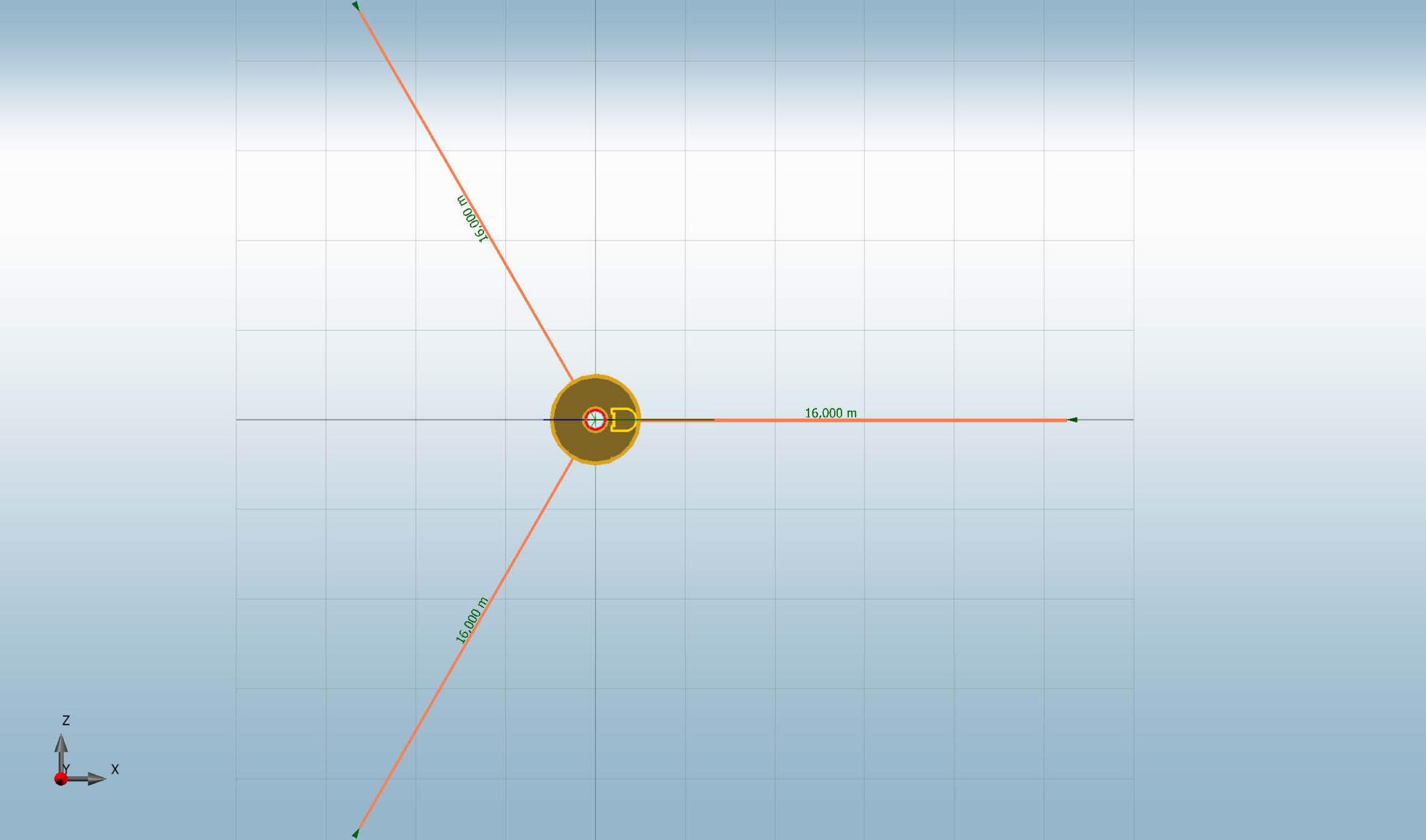
3.4 DEADMAN INFORMATION: MATERIAL: A36 Set # DM # Radius Elev Orien m m Deg ----- ---- ------- ------- ------ 1 1 16,00 0,00 0,0 1 2 16,00 0,00 120,0 1 3 16,00 0,00 240,0
3.5 Attachment at Stack 3.5.1 PIPING: Description Top El Bot El Nom Dia Qty Act Dia Pipe Thickness Insul Thk m m mm mm Schedule mm mm --------------- ------- ------- ------- ----- ------- -------- --------- --------- fuel gas pipe 29,00 5,00 25,400 1 33,4 80 4,5 0,0 conduit pipe 29,00 1,00 38,100 6 21,0 STD 3,7 0,0
3.5.2 PLATFORMS: Plat Elev Start Ang End Ang Width Stack OD Weight m Deg Deg m m kg --------- --------- ------- ------- -------- ------- 28,25 0 360 1,067 0,660 185 19,00 0 90 1,067 0,660 137 9,50 0 90 1,067 0,660 137 2,25 0 360 1,067 0,660 185
3.5.3 LADDERS: Top Elev Bot Elev Type of Ladder Weight Area m m kg/m m ^2 -------- -------- ------------------------ ------ ----- 29,00 19,00 Caged Ladder Only 34,2 0,07 20,00 9,50 Caged Ladder Only 34,2 0,07 10,50 2,25 Caged Ladder Only 34,2 0,07 3,25 0,00 0,0 0,00 3.5.4 FLARE TIP Outer Diameter = 26 inch Overall Length = 3000 mm Number of Pilots = 3 ea Flare Tip Weight = 6000 N
3.6 BASEPLATE INFORMATION: A 36 Ds: Outer Diameter of Stack at Base = 660,0 mm Di: Inside Diameter of Baseplate = 609,0 mm Dbc: Bolt Circle Diameter = 774,0 mm Do: Outside Diameter of Baseplate = 870,0 mm Tb: Thickness of Bottom Plate = 25,0 mm Fw: Fillet Welds = 6,0 mm Db: Nominal Bolt Diameter = 32,0 mm Dbh: Diameter of Bolt Hole = 38,0 mm Nb: Number of Bolts = 8 Fu: Ultimate Bolt Tensile Stress = 399898 KPa CA: Total Corrosion Allowance for Bolts and Baseplate = 1,0000 mm Ec: Modulus of Elasticity of Concrete = 20684400,0E+ KPa Fc: Allowable Compressive Stress of Concrete = 10561 KPa Fy: Yield Stress of Baseplate Material = 226536 KPa Es: Modulus of Elasticity of Baseplate = 197000000,0E+ KPa Dens: Density of Baseplate = 7849,0 kg/m^3 u: Poisons Ratio for Baseplate Material = 0,30

FLARE STACK CALCULATION
DOCUMENT NUMBER REV. CONTRACT NO. : EP37-M12LL0122D Page 6 of 28 GCMT-13-MS-CN-FLR-001 2 JOB NO. : 31-12008PO053
Ngus: Number of Gussets per Bolt = 2 hg: Height of Gusset = 152,0 mm tg: Thickness of Gusset = 12,0 mm wg: Spacing of Gussets = 127,0 mm 3.7 Guy Lug INFORMATION Single Ring : A36 Elev A B D Bt Hd Rt Rt1 Rs Pt Pd Tw m mm mm mm mm mm mm mm mm mm mm mm ------------------------------------------------------------------------------------ 27,50 102,0 64,0 102,0 17,0 38,0 19,0 19,0 25,0 10,0 114,0 10,0 Notes: Elev = Elevation of Guy Lug A = Pad OD to Center of Hole B = Radius of Corner D = Hole Center to Top of Lug Bt = Thickness of Guy Lug Hd = Diameter of Hole Rt = Thk of Top Stiffening Ring Rt1 = Thk of Reinf. Ring Rs = Top of Stiffener to Reinf. Ring Pt = Thickness of Repad Pd = Diameter of Repad Tw = Fillet Welds
3.8 DAMPING CALCULATIONS: Structural Damping Criteria: ASME STS-1-2011 Lining : UNLINED Support : RIGID Bs : 0,006 Log Decrement Damp : 0,0377 Aerodynamic Damping Criteria: ASME STS-1-2011
3.9 DEFLECTION LIMITS: DEFLECTION LIMITS: Ht/200 = 160 mm 3.10 FATIGUE: Design Code : American Institute of Steel Construction ASD 9th Ed. Fatigue Life : 20 Years Number of Cycles : Calculated per ASME STS-1-2011 Appendix E-5 Stress Category : C
VORTEX SHEDDING CODE: ASME STS-1-2011 Stack Arrangement : SINGLE 3.11 ALONG WIND CODE: ASCE 7-05 Wind Speed : 13,4 m/s Exposure : C Structural Category : 3 Importance Factor : 1,15 Shape Factor (Piping D*qz^0.5 > 2.5) : 0,700 Shape Factor (Piping D*qz^0.5 < 2.5) : 1,200 Shape Factor (L&P's) : 2,000 Stack Enclosed to Elev : 0,0 m (No wind below this elev) Stack Elev above Grade : 0,0 m (used for gust calculations) 3.12 SEISMIC CODE: Uniform Building Code 1997 Seismic Zone : 3 Site Coefficient : SE Importance Factor : 1,25 Rw : 2,9 Seismic Source Type : A Closest Dist to Source : 15KM 3.13 PRESSURE: Elevation Pressure Joint Eff Circum Joint Eff Longitudinal m KPa/psi --------- -------- ---------------- ---------------------- 32,00 248,20/36 0,850 0,850

FLARE STACK CALCULATION
DOCUMENT NUMBER REV. CONTRACT NO. : EP37-M12LL0122D Page 7 of 28 GCMT-13-MS-CN-FLR-001 2 JOB NO. : 31-12008PO053
3.14 EXTERNAL LOADS: Description Elev Shear Vertical Moment Load Type m N N N-m --------------------------- ------- -------- -------- -------- -------------------- Flare Header 2,60 3338 4673 2021 OPERATING 4.0 APPLICATION SOFTWARE
Mecastack 5.2.6.4, Flare Stack Calculation program, has been applied for this calculation.
5.0 RESULTS
5.1 C A B L E L O A D I N G S (M A X I M U M L O A D S U M M A R Y)
DETAILED GUY WIRE LOADS (Units in KN ) Positive Forces are Tensile Loads, and Negative are Reductions in Tensile Loads
Set Ld Load Case Dir Guy Guy Guy Max Unity Result (P)=Primary (C)=Combination Deg # 1 # 2 # 3 Tension Ratio ---------------------------------------------------------------------------------------- 1 1PASS ALL -0,18 -0,18 -0,18 0,00 0,00 PASS 1 2(P)PRETENSION GUY WIRE ALL 16,21 16,21 16,21 16,21 0,30 PASS 1 3(P)LIVE ALL -0,18 -0,18 -0,18 0,00 0,00 PASS 1 4(P)OPERATING ALL -0,07 0,03 0,03 0,03 0,00 PASS 1 5(P)THERMAL COLD ALL 2,03 2,03 2,03 2,03 0,04 PASS 1 6(P)THERMAL HOT ALL 11,15 11,15 11,15 11,15 0,20 PASS 1 7(P)WIND @ 0 Deg 0 -2,80 1,41 1,41 1,41 0,03 PASS 1 8(P)WIND @ 30 Deg 30 -2,43 0,00 2,44 2,44 0,04 PASS 1 9(P)WIND @ 60 Deg 60 -1,40 -1,40 2,81 2,81 0,05 PASS 1 10(P)SEISMIC @0 Deg 0 -15,12 18,57 18,57 18,57 0,34 PASS 1 11(P)SEISMIC @30 Deg 30 -14,89 4,40 25,05 25,05 0,46 PASS 1 12(P)SEISMIC @60 Deg 60 -10,94 -12,61 26,51 26,51 0,48 PASS 1 13(P)VORTEX STATIC @ 0 Deg* 0 0,00 0,61 -0,61 0,61 0,01 PASS 1 14(P)VORTEX STATIC @ 30 Deg* 30 -0,35 0,70 -0,35 0,70 0,01 PASS 1 15(P)VORTEX STATIC @ 60 Deg* 60 -0,60 0,61 -0,00 0,61 0,01 PASS 1 16(P)VORTEX FATIGUE @ 90 Deg 90 0,00 0,30 -0,30 0,30 0,01 PASS 1 17(P)VORTEX FATIGUE @ 120 Deg 120 -0,17 0,35 -0,18 0,35 0,01 PASS 1 18(P)VORTEX FATIGUE @ 150 Deg 150 -0,30 0,30 -0,00 0,30 0,01 PASS 1 19(C)Wind Comb Hot w Live 0 24,84 28,12 28,13 28,13 0,51 PASS 1 20(C)Wind Comb Hot w Live 30 25,12 27,06 28,90 28,90 0,53 PASS 1 21(C)Wind Comb Hot w Live 60 25,90 26,00 29,19 29,19 0,53 PASS 1 22(C)Wind Comb Hot no Live 0 24,27 28,61 28,61 28,61 0,52 PASS 1 23(C)Wind Comb Hot no Live 30 24,65 27,19 29,65 29,65 0,54 PASS 1 24(C)Wind Comb Hot no Live 60 25,68 25,78 30,02 30,02 0,55 PASS 1 25(C)Wind Comb Cold w Live 0 15,73 19,01 19,02 19,02 0,35 PASS 1 26(C)Wind Comb Cold w Live 30 16,02 17,95 19,79 19,79 0,36 PASS 1 27(C)Wind Comb Cold w Live 60 16,79 16,89 20,08 20,08 0,37 PASS 1 28(C)Wind Comb Cold no Live 0 15,17 19,50 19,50 19,50 0,36 PASS 1 29(C)Wind Comb Cold no Live 30 15,54 18,09 20,53 20,53 0,38 PASS 1 30(C)Wind Comb Cold no Live 60 16,58 16,68 20,91 20,91 0,38 PASS 1 31(C)Seismic Comb Hot 0 10,16 35,50 35,50 35,50 0,65 PASS 1 32(C)Seismic Comb Hot 30 12,39 27,06 41,63 41,63 0,76 PASS 1 33(C)Seismic Comb Hot 60 18,52 17,39 45,12 45,12 0,83 PASS 1 34(C)Seismic Comb Cold 0 2,48 27,43 27,43 27,43 0,50 PASS 1 35(C)Seismic Comb Cold 30 3,89 18,40 32,95 32,95 0,60 PASS 1 36(C)Seismic Comb Cold 60 9,58 8,46 36,11 36,11 0,66 PASS 1 37(C)Vortex Comb Hot 0 27,09 27,81 26,59 27,81 0,51 PASS 1 38(C)Vortex Comb Hot 30 26,74 27,90 26,84 27,90 0,51 PASS 1 39(C)Vortex Comb Hot 60 26,48 27,81 27,20 27,81 0,51 PASS 1 40(C)Vortex Comb Cold 0 17,98 18,69 17,48 18,69 0,34 PASS 1 41(C)Vortex Comb Cold 30 17,63 18,79 17,73 18,79 0,34 PASS 1 42(C)Vortex Comb Cold 60 17,37 18,70 18,09 18,70 0,34 PASS

FLARE STACK CALCULATION
DOCUMENT NUMBER REV. CONTRACT NO. : EP37-M12LL0122D Page 8 of 28 GCMT-13-MS-CN-FLR-001 2 JOB NO. : 31-12008PO053
5.2. Foundation Loading 5.2.1 Load Acting on Deadman Load Load Case Dir Fx Fy Fz Shear (P)=Primary, (C)=Combination Deg KN KN KN KN -------------------------------------------------------------------------------- 1 (P)DEAD ALL -0,00 -70,73 0,00 0,00 2 (P)PRETENSION GUY WIRE ALL 0,00 0,00 -0,00 0,00 3 (P)LIVE ALL 0,00 -72,36 0,00 0,00 4 (P)OPERATING ALL 3,34 -4,67 0,00 3,34 5 (P)THERMAL COLD ALL -0,00 -0,00 -0,00 0,00 6 (P)THERMAL HOT ALL -0,00 0,00 -0,00 0,00 7 (P)WIND @ 0 Deg 0 4,72 -0,00 0,00 4,72 8 (P)WIND @ 30 Deg 30 4,09 0,00 2,36 4,72 9 (P)WIND @ 60 Deg 60 2,36 -0,00 4,09 4,72 10 (P)SEISMIC @0 Deg 0 27,44 -0,00 0,00 27,44 11 (P)SEISMIC @30 Deg 30 23,76 0,00 13,72 27,44 12 (P)SEISMIC @60 Deg 60 13,72 0,00 25,14 28,64 13 (P)VORTEX STATIC @ 0 Deg* 0 0,00 0,00 0,81 0,81 14 (P)VORTEX STATIC @ 30 Deg* 30 -0,40 0,00 0,70 0,81 15 (P)VORTEX STATIC @ 60 Deg* 60 -0,70 -0,00 0,40 0,81 16 (P)VORTEX FATIGUE @ 90 Deg 90 -0,00 -0,00 0,40 0,40 17 (P)VORTEX FATIGUE @ 120 Deg 120 -0,20 -0,00 0,35 0,40 18 (P)VORTEX FATIGUE @ 150 Deg 150 -0,35 -0,00 0,20 0,40 19 (C)Wind Comb Hot w Live 0 6,88 -129,68 -0,00 6,88 20 (C)Wind Comb Hot w Live 30 6,40 -129,68 1,77 6,64 21 (C)Wind Comb Hot w Live 60 5,11 -129,68 3,06 5,96 22 (C)Wind Comb Hot no Live 0 8,06 -75,41 0,00 8,06 23 (C)Wind Comb Hot no Live 30 7,42 -75,41 2,36 7,79 24 (C)Wind Comb Hot no Live 60 5,70 -75,41 4,09 7,01 25 (C)Wind Comb Cold w Live 0 6,88 -129,68 -0,00 6,88 26 (C)Wind Comb Cold w Live 30 6,40 -129,68 1,77 6,64 27 (C)Wind Comb Cold w Live 60 5,11 -129,68 3,06 5,96 28 (C)Wind Comb Cold no Live 0 8,06 -75,41 0,00 8,06 29 (C)Wind Comb Cold no Live 30 7,42 -75,41 2,36 7,79 30 (C)Wind Comb Cold no Live 60 5,70 -75,41 4,09 7,01 31 (C)Seismic Comb Hot 0 22,55 -147,77 0,00 22,55 32 (C)Seismic Comb Hot 30 19,97 -147,77 9,60 22,16 33 (C)Seismic Comb Hot 60 12,94 -147,77 17,60 21,85 34 (C)Seismic Comb Cold 0 22,55 -147,77 -0,00 22,55 35 (C)Seismic Comb Cold 30 19,97 -147,77 9,60 22,16 36 (C)Seismic Comb Cold 60 12,94 -147,77 17,60 21,85 37 (C)Vortex Comb Hot 0 3,34 -75,41 0,81 3,43 38 (C)Vortex Comb Hot 30 2,93 -75,41 0,70 3,02 39 (C)Vortex Comb Hot 60 2,64 -75,41 0,40 2,67 40 (C)Vortex Comb Cold 0 3,34 -75,41 0,81 3,43 41 (C)Vortex Comb Cold 30 2,93 -75,41 0,70 3,02 42 (C)Vortex Comb Cold 60 2,64 -75,41 0,40 2,67 Notes: Vertical = Force acting in vertical direction (+ is acting upward, - is acting downard) Shear = Lateral force (Fx^2+Fz^2)^0.5 Moment = Overturning moment on foundation (Mx^2+Mz^2)^0.5 Torsion = Torsional moment about vertical axis (My).

FLARE STACK CALCULATION
DOCUMENT NUMBER REV. CONTRACT NO. : EP37-M12LL0122D Page 9 of 28 GCMT-13-MS-CN-FLR-001 2 JOB NO. : 31-12008PO053
5.3 GUY WIRE HARDWARE FOR SET # 1 @ ELEV.27,5 m Guy Wire to Stack Connection = Rope Clips Rope Clips: Wire Rope Clip Type = U-Bolt Rope Clips: Number of Wire Rope Clips per Guy = 4 Rope Clips: Cable Turnback = 457,20 mm Rope Clips: Clip Spacing (Wc) = 107,95 mm Rope Clips: Torque on U-bolts = 176,25 N-m Rope Clips: Clip Weight(each) = 0,64 kg Rope Clips: Clip - Crosby Model # = G-450 Thimble: Width (D) = 50,80 mm Thimble: Length (B) = 95,25 mm Thimble: Weight(each) = 0,72 kg Thimble: Model # = G-414 Shackle: Pin Diameter = 31,75 mm Shackle: Inside Clearance = 123,95 mm Shackle: Jaw Width = 45,97 mm Shackle: Weight(each) = 3,76 kg Shackle: Working Load = 42,26 KN Shackle: Model # = G-2130 Guy Wire to Deadman Connection = Turnbuckle Rope Clips: Wire Rope Clip Type = U-Bolt Rope Clips: Number of Wire Rope Clips per Guy = 4 Rope Clips: Cable Turnback = 457,20 mm Rope Clips: Clip Spacing (Wc) = 107,95 mm Rope Clips: Torque on U-bolts = 176,25 N-m Rope Clips: Clip Weight(each) = 0,64 kg Rope Clips: Clip - Crosby Model # = G-450 Thimble: Width (D) = 50,80 mm Thimble: Length (B) = 95,25 mm Thimble: Weight(each) = 0,72 kg Thimble: Model # = G-414 Turnbuckle Type = Jaw-Jaw Turnbuckle: Size = 1.50X24 Turnbuckle: Model # = HG-228 Turnbuckle: Weight # = 18,87 kg Turnbuckle: Capacity = 95195,8 N Turnbuckle: Half Length = 1355,9 mm Turnbuckle-Jaw Side: Pin Diameter = 35,05 mm Turnbuckle-Jaw Side: Jaw Width = 57,15 mm Turnbuckle-Jaw Side: Inside Clearance = 88,90 mm Both ends of the Turnbuckle(Jaw-Jaw) are exactly the same. DEADMAN: DM # Length Pin to Pin Purchased Cable Length m m ---- ----------------- ---------------------- 1 31,59 34,27 2 31,59 34,27 3 31,59 34,27 Notes: Assumes 1/2 open 'TakeUp' or 'Turnbuckle' Length Pin to Pin = Length of cable plus the 1/2 open turnbuckle length. Purchased Cable Length = Length from the Pin on the Stack to the thimble eye + Turnback + extra 10%

FLARE STACK CALCULATION
DOCUMENT NUMBER REV. CONTRACT NO. : EP37-M12LL0122D Page 10 of 28GCMT-13-MS-CN-FLR-001 2 JOB NO. : 31-12008PO053
5.4 WEIGHT SUMMARY Component Elev COG Weight m kg ------------------------------------- ---------- -------- Cylinders (Corroded Wt = 2959 lbs) 14,50 4433 Ladders 14,26 1081 Platforms 15,22 644 Piping 13,13 310 Flare Tip 30,50 612 Baseplate 0,03 76 Guy Lugs 27,50 154 ------------------------------------- ---------- -------- Total 15,93 7309
5.5 WIND AREA SUMMARY Elev Riser Ladder Platform Piping Attachment Ext Loads Total m m m m m m m m ------- ------- -------- ---------- -------- ------------ ----------- ------- 32,00 0,70 0,00 0,00 0,00 0,00 0,00 0,70 29,00 0,46 0,00 0,00 0,00 0,00 0,00 0,46 28,91 0,46 0,00 2,79 0,00 0,00 0,00 3,26 28,52 0,46 0,46 2,79 0,00 0,00 0,00 3,71 28,00 0,46 0,46 0,00 0,00 0,00 0,00 0,92 27,65 0,46 0,46 0,00 0,00 0,00 0,00 0,92 27,61 0,46 0,46 0,00 0,00 0,57 0,00 1,49 27,50 0,46 0,46 0,00 0,00 0,57 0,00 1,49 27,41 0,46 0,46 0,00 0,00 0,00 0,00 0,92 24,41 0,46 0,46 0,00 0,00 0,00 0,00 0,92 23,00 0,46 0,46 0,00 0,16 0,00 0,00 1,08 20,00 0,46 0,46 0,00 0,22 0,00 0,00 1,14 19,52 0,46 0,69 0,00 0,22 0,00 0,00 1,37 18,91 0,46 0,69 1,73 0,22 0,00 0,00 3,09 18,00 0,46 0,46 0,00 0,22 0,00 0,00 1,14 15,00 0,46 0,46 0,00 0,22 0,00 0,00 1,14 12,00 0,46 0,46 0,00 0,22 0,00 0,00 1,14 10,52 0,46 0,69 0,00 0,22 0,00 0,00 1,37 9,91 0,46 0,69 1,73 0,22 0,00 0,00 3,09 9,00 0,46 0,46 0,00 0,22 0,00 0,00 1,14 7,00 0,46 0,46 0,00 0,22 0,00 0,00 1,14 5,91 0,46 0,46 2,79 0,22 0,00 0,00 3,93 5,00 0,46 0,46 0,00 0,06 0,00 0,00 0,98 2,00 0,46 0,46 0,00 0,06 0,00 0,00 0,98 1,00 0,46 0,46 0,00 0,00 0,00 0,00 0,92 0,15 0,46 0,46 0,00 0,00 1,28 0,00 2,20 Notes: * All areas include appropriate shape factors * Any wind area due to external insulation/refractory included in Riser

FLARE STACK CALCULATION
DOCUMENT NUMBER REV. CONTRACT NO. : EP37-M12LL0122D Page 11 of 28GCMT-13-MS-CN-FLR-001 2 JOB NO. : 31-12008PO053
5.6 CORRODED STACK PROPERTIES Top El Bot El D Thick r Area Z Smod Imom m m m mm mm cm^2 cm^3 cm^3 cm^4 ------------------------------------------------------------------------------------ 32,00 29,00 0,66000 5,9999 231,234 123,24 2566,32 1997,37 65908,37 29,00 28,91 0,66000 6,3300 231,118 129,96 2704,78 2104,09 69429,90 28,91 28,52 0,66000 6,3300 231,118 129,96 2704,78 2104,09 69429,90 28,52 28,00 0,66000 6,3300 231,118 129,96 2704,78 2104,09 69429,90 28,00 27,65 0,66000 6,3300 231,118 129,96 2704,78 2104,09 69429,90 27,65 27,61 0,66000 6,3300 231,118 129,96 2704,78 2104,09 69429,90 27,61 27,50 0,66000 6,3300 231,118 129,96 2704,78 2104,09 69429,90 27,50 27,41 0,66000 6,3300 231,118 129,96 2704,78 2104,09 69429,90 27,41 24,41 0,66000 6,3300 231,118 129,96 2704,78 2104,09 69429,90 24,41 23,00 0,66000 6,3300 231,118 129,96 2704,78 2104,09 69429,90 23,00 20,00 0,66000 6,3300 231,118 129,96 2704,78 2104,09 69429,90 20,00 19,52 0,66000 6,3300 231,118 129,96 2704,78 2104,09 69429,90 19,52 18,91 0,66000 6,3300 231,118 129,96 2704,78 2104,09 69429,90 18,91 18,00 0,66000 6,3300 231,118 129,96 2704,78 2104,09 69429,90 18,00 15,00 0,66000 6,3300 231,118 129,96 2704,78 2104,09 69429,90 15,00 12,00 0,66000 6,3300 231,118 129,96 2704,78 2104,09 69429,90 12,00 10,52 0,66000 6,3300 231,118 129,96 2704,78 2104,09 69429,90 10,52 9,91 0,66000 6,3300 231,118 129,96 2704,78 2104,09 69429,90 9,91 9,00 0,66000 6,3300 231,118 129,96 2704,78 2104,09 69429,90 9,00 7,00 0,66000 6,3300 231,118 129,96 2704,78 2104,09 69429,90 7,00 5,91 0,66000 6,3300 231,118 129,96 2704,78 2104,09 69429,90 5,91 5,00 0,66000 6,3300 231,118 129,96 2704,78 2104,09 69429,90 5,00 2,00 0,66000 6,3300 231,118 129,96 2704,78 2104,09 69429,90 2,00 1,00 0,66000 6,3300 231,118 129,96 2704,78 2104,09 69429,90 1,00 0,15 0,66000 6,3300 231,118 129,96 2704,78 2104,09 69429,90 0,15 0,00 0,66000 6,3300 231,118 230,73 2704,78 3291,32 143162,30

FLARE STACK CALCULATION
DOCUMENT NUMBER REV. CONTRACT NO. : EP37-M12LL0122D Page 12 of 28GCMT-13-MS-CN-FLR-001 2 JOB NO. : 31-12008PO053
5.7 SUMMARIZED WORST STRESSES RATIOS
STACK STRESS WORST CASE SUMMARY Summary of the load and highest stress ratios for each stack element
Top El Bot El Load # Load Case Controlling Case Ratio Result m m --------------------------------------------------------------------------------------- 32,00 29,00 19 Wind Comb Hot w Live Circumferential Tensile 0,14 PASS 29,00 28,91 19 Wind Comb Hot w Live Circumferential Tensile 0,11 PASS 28,91 28,52 19 Wind Comb Hot w Live Circumferential Tensile 0,11 PASS 28,52 28,00 19 Wind Comb Hot w Live Circumferential Tensile 0,11 PASS 28,00 27,65 19 Wind Comb Hot w Live Circumferential Tensile 0,11 PASS 27,65 27,61 19 Wind Comb Hot w Live Circumferential Tensile 0,11 PASS 27,61 27,50 19 Wind Comb Hot w Live Circumferential Tensile 0,11 PASS 27,50 27,41 19 Wind Comb Hot w Live Circumferential Tensile 0,11 PASS 27,41 24,41 19 Wind Comb Hot w Live Circumferential Tensile 0,11 PASS 24,41 23,00 31 Bending, Comp & Circumfer 0,11 PASS 23,00 20,00 31 Bending, Comp & Circumfer 0,13 PASS 20,00 19,52 31 Bending, Comp & Circumfer 0,13 PASS 19,52 18,91 31 Bending, Comp & Circumfer 0,13 PASS 18,91 18,00 31 Bending, Comp & Circumfer 0,13 PASS 18,00 15,00 31 Bending, Comp & Circumfer 0,12 PASS 15,00 12,00 19 Wind Comb Hot w Live Circumferential Tensile 0,11 PASS 12,00 10,52 33 Bending, Comp & Circumfer 0,11 PASS 10,52 9,91 33 Bending, Comp & Circumfer 0,12 PASS 9,91 9,00 33 Bending, Comp & Circumfer 0,14 PASS 9,00 7,00 33 Bending, Comp & Circumfer 0,18 PASS 7,00 5,91 34 Bending, Comp & Circumfer 0,22 PASS 5,91 5,00 34 Bending, Comp & Circumfer 0,25 PASS 5,00 2,00 34 Bending, Comp & Circumfer 0,37 PASS 2,00 1,00 34 Bending, Comp & Circumfer 0,40 PASS 1,00 0,15 34 Bending, Comp & Circumfer 0,44 PASS 0,15 0,00 34 Bending, Comp & Circumfer 0,27 PASS 5.8 DEFLECTION SUMMARY Elev Load Load Case Max Lateral Defl Allowable Result m mm mm ------- ----- ----------------------------- ---------------- --------- ---------------- 32,00 34 Seismic Comb Cold 94,95 160,00 PASS 29,00 34 Seismic Comb Cold 86,30 145,00 PASS 28,91 34 Seismic Comb Cold 86,06 144,57 PASS 28,52 34 Seismic Comb Cold 84,97 142,62 PASS 28,00 34 Seismic Comb Cold 83,52 140,00 PASS 27,65 34 Seismic Comb Cold 82,55 138,23 PASS 27,61 34 Seismic Comb Cold 82,45 138,04 PASS 27,50 34 Seismic Comb Cold 82,16 137,50 PASS 27,41 34 Seismic Comb Cold 81,92 137,06 PASS 24,41 34 Seismic Comb Cold 73,83 122,06 PASS 23,00 34 Seismic Comb Cold 69,89 115,00 PASS 20,00 34 Seismic Comb Cold 60,82 100,00 PASS 19,52 34 Seismic Comb Cold 59,29 97,62 PASS 18,91 34 Seismic Comb Cold 57,28 94,57 PASS 18,00 34 Seismic Comb Cold 54,18 90,00 PASS 15,00 34 Seismic Comb Cold 43,35 75,00 PASS 12,00 34 Seismic Comb Cold 31,92 60,00 PASS 10,52 34 Seismic Comb Cold 26,29 52,62 PASS 9,91 34 Seismic Comb Cold 23,99 49,57 PASS 9,00 34 Seismic Comb Cold 20,61 45,00 PASS 7,00 34 Seismic Comb Cold 13,61 35,00 PASS 5,91 34 Seismic Comb Cold 10,15 29,57 PASS 5,00 34 Seismic Comb Cold 7,50 25,00 PASS 2,00 34 Seismic Comb Cold 1,29 10,00 PASS 1,00 34 Seismic Comb Cold 0,31 5,00 PASS 0,15 34 Seismic Comb Cold 0,00 0,76 PASS
FLARE STACK CALCULATION
DOCUMENT NUMBER REV. CONTRACT NO. : EP37-M12LL0122D Page 13 of 28GCMT-13-MS-CN-FLR-001 2 JOB NO. : 31-12008PO053
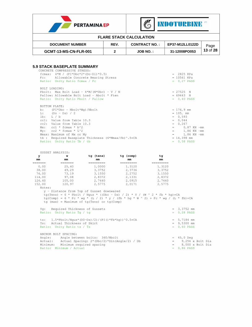
5.9 STACK BASEPLATE SUMMARY CONCRETE COMPRESSIVE STRESS: fcmax: 4*M / (PI*Dbc*2*(Do-Di)*0.5) = 2825 KPa Fc: Allowable Concrete Bearing Stress = 10561 KPa Ratio: Unity Ratio fcmax / Fc = 0,27 PASS BOLT LOADING: Pbolt: Max Bolt Load - 4*M/(N*Dbc) - V / N = 27525 N Pallow: Allowable Bolt Load - Abolt * Ften = 69443 N Ratio: Unity Ratio Pbolt / Pallow = 0,40 PASS BOTTOM PLATE: b: (PI*Dbc - Nbolt*Wg)/Nbolt = 176,9 mm L: (Do - Ds) / 2 = 105, mm lb: L / b = 0,593 cc1: Value from Table 10.3 = 0,044 cc2: Value from Table 10.3 = 0,267 Mx: cc1 * fcmax * b^2 = 0,87 KN -mm My: cc2 * fcmax * L^2 = 1,86 KN -mm Mmax: Maximum of Mx or My = 1,86 KN -mm tb : Required Baseplate Thickness (6*Mmax/fb)^.5+CA = 14,398 mm Ratio: Unity Ratio Tb / tb = 0,58 PASS GUSSET ANALYSIS: y w tg (tens) tg (comp) tg mm mm mm mm mm ------- ------- --------- --------- --------- 0,00 25,40 1,0000 1,3120 1,3120 38,00 49,29 3,3752 2,3736 3,3752 76,00 73,19 3,1550 2,2752 3,1550 114,00 97,08 2,8372 2,1331 2,8372 126,60 105,00 2,7440 2,0915 2,7440 152,00 120,97 2,5775 2,0171 2,5775 Notes: y - Distance from Top of Gusset downwared tg(Tens) = 6 * Pbolt / Ngus * ((Dbc - Ds) / 2) * Y / (W ^ 2 * fb * hg)+CA tg(Comp) = 6 * Fc * wg * (L / 2) * y / (fb * hg * W ^ 2) + Fc * wg / (L * fb)+CA tg (max) = Maximum of tg(Tens) or tg(Comp) Tg: Required Thickness of Gussets = 3,3752 mm Ratio: Unity Ratio Tg / tg = 0,28 PASS ts: 1.5*Pbolt/Ngus*(D0-Ds)/2)/(PI()*Fb*hg))^0.5+CA = 5,7184 mm Ts: Actual Thickness of Skirt = 9,5300 mm Ratio: Unity Ratio ts / Ts = 0,60 PASS ANCHOR BOLT SPACING: Angle: Angle between bolts: 360/Nbolt = 45,0 Deg Actual: Actual Spacing: 2*(Dbc/2)*Sin(Angle/2) / Db = 9,256 x Bolt Dia Minimum: Minimum required spacing = 8,000 x Bolt Dia Ratio: Minimum / Actual = 0,86 PASS

FLARE STACK CALCULATION
DOCUMENT NUMBER REV. CONTRACT NO. : EP37-M12LL0122D Page 14 of 28GCMT-13-MS-CN-FLR-001 2 JOB NO. : 31-12008PO053
5.10 Guy Lug #1 Analysis @ 27,5 m
Guy Single Lug Analysis - Guy Set # 1 Checked for the maximum cable load for this set of guy wires
Load: Maximum Cable Tensile Load = 45,3 KN Angle: Cable Angle to Horizontal = 59,8 Degrees CA: Cos (Angle) = 0,5 SA: Sin (Angle) = 0,9 HL: Horizontal Load Component (Pmax * CA) = 22,8 KN HV: Vertical Load Component (Pmax * SA) = 39,2 KN Ft: Allowable Tensile Stress: 0,600* Fy = 132,2 MPa Fv: Allowable Shear Stress: 0,400* Fy = 88,2 MPa Fb: Allowable Bending Stress: 0,660* Fy = 145,5 MPa Fbr: Allowable Bearing Stress (Fy) = 220,4 MPa Stresses on Plane a-a Aaa: Area of Section (B + D - Hd)*Bt = 2176,0 mm^2 ft: Tensile Stress (HL / Aaa) = 10,5 MPa Ratio: Unity Ratio ft / Ft = 0,08 PASS fv: Shear Stress (HV / Aaa) = 18,0 MPa PASS --> Shear Stress is Acceptable. Ratio: Unity Ratio = 0,20 PASS Stresses on Plane b-b Sbb: Sec Modulus (B + D)^2 * Bt / 6 = 78051, mm^3 Abb: Area of Section (B + D) * Bt = 2822,0 mm^2 Mbb: Bending Moment HV * (B + D) / 2 = 3998,5 KN-mm ft: Tensile Stress (Mbb / Sbb + HL / Abb) = 59,3 MPa Ratio: Unity Ratio = 0,45 PASS Check Welding of Lug: Aw: Weld Area: (B+D)*2*Tw*0.707 = 2347,2 mm^2 Sw: Section modulus of weld: 0.707*Tw*(B+D)^2 / 6 = 32460, mm^3 fw: Weld stress: Hl/Aw + Hv*A/Sw = 132,8 MPa Fw: Allowable weld stress: 0.3*70 ksi [482 MPa] = 144,8 MPa Ratio: Unity Ratio = 0,92 PASS fv: Shear Stress (HV / Abb) = 13,9 MPa Ratio: Unity Ratio = 0,16 PASS r: (OD/2) + (A+B)/2 + Rt1 = 432,0 mm w: HL / (2 * PI * r) = 0,0 KN /mm Mmax: 1.5 * w * r^2 = 2352,2 KN-mm Fmax: w * r / 2 = 1,8 KN Ring Properties Zg: Center of Gravity = 42,9 mm I: Moment of Inertia = 25193880,0E+ mm^4 S: Section Modulus = 586730,9 mm^3 A: Area = 8308,8 mm^2 fb: Ring Bending Stess (Max / S + Fmax / A) = 4,2 MPa Ratio: Unity Ratio = 0,03 PASS Check Shackle Type: Guy Wire Type = IWRC Dia: Guy Wire Diameter = 19,1 mm B: Shackle Pin Diameter = 31,8 mm Hd: Hole Diameter = 38,0 mm PASS --> Shackle Pin will work with this Lug. C+B/2: Shackle Inside Clearance = 124,0 mm B: Radius of corner of Lug = 64,0 mm PASS --> The Shackle has adequate clearance.

FLARE STACK CALCULATION
DOCUMENT NUMBER REV. CONTRACT NO. : EP37-M12LL0122D Page 15 of 28GCMT-13-MS-CN-FLR-001 2 JOB NO. : 31-12008PO053
Ttot: Total Thickness of Lug (Bt + 2 * Pt) = 37,0 mm A: Shackle Jaw Spacing = 46,0 mm PASS --> The clearance is adequate. Shackle Model # = G-2130 fbr: Bearing Stress (Pmax / (D * (Bt + 2 * Pt))) = 38,6 MPa Ratio: Unity Ratio = 0,18 PASS As: (B - Hd / 2)* Bt + (Pd / 2 -Hd / 2) * Pt = 1525,0 mm^2 fs: Shear Tearout (Pmax / (2 * As) = 14,9 MPa Ratio: Unity Ratio = 0,17 PASS Pmax: Maximum Tensile Load in Cable = 45,3 KN TCp: Turnbuckle Capacity = 95,2 KN PASS --> The Turnbuckle Capacity is Acceptable. Description Units Actual Allow SR Result ---------------------- -------- -------- -------- ------ -------- Plane a-a: Tension MPa 6,76 85,32 0,08 PASS Plane a-a: Shear MPa 11,62 56,88 0,20 PASS Plane b-b: Tension MPa 38,24 85,32 0,45 PASS Plane b-b: Shear MPa 8,96 56,88 0,16 PASS Ring Bending Stress MPa 2,73 93,86 0,03 PASS Pin Bearing Stress MPa 24,90 142,21 0,18 PASS Pin Shear Tearout MPa 9,59 56,88 0,17 PASS Weld Stress MPa 85,69 93,42 0,92 PASS Turnbuckle Capacity KN 45,34 95,20 0,48 PASS

FLARE STACK CALCULATION
DOCUMENT NUMBER REV. CONTRACT NO. : EP37-M12LL0122D Page 16 of 28GCMT-13-MS-CN-FLR-001 2 JOB NO. : 31-12008PO053
6.0 ATTACHMENT
Attachment – 1 : Drawing Output Software

GUY WIRE HARDWARE FOR SET # 1 @ ELEV. 27,50 m
Guy Wire to Stack Connection:
Cable Size = 19,05 mm
Pretension = 16,4 KN
Cable Type = IWRC
Cable Breaking Strength = 204,98 KN
Rope Clips: Wire Rope Clip Type = U-Bolt
Rope Clips: # of Wire Rope Clips per Guy = 4
Rope Clips: Cable Turnback = 457,2 mm
Rope Clips: Clip Spacing = 107,95 mm
Rope Clips: Torque on U-bolts = 176,254 N-m
Rope Clips: Clip Weight(each) = 0,644112 kg
Rope Clips: Clip - Crosby Model # = G-450
Thimble: Width (D) = 50,8 mm
Thimble: Length (B) = 95,25 mm
Thimble: Weight(each) = 0,716688 kg
Thimble: Model # = G-414
Shackle: Pin Diameter = 31,75 mm
Shackle: Inside Clearance = 123,952 mm
Shackle: Jaw Width = 45,974 mm
Shackle: Weight(each) = 3,76488 mm
Shackle: Working Load = 42,2598 KN
Shackle: Model # = G-2130
Guy Wire to Deadman Connection:
Rope Clips: Wire Rope Clip Type = U-Bolt
Rope Clips: # of Wire Rope Clips per Guy = 4
Rope Clips: Cable Turnback = 457,20 mm
Rope Clips: Clip Spacing (Wc) = 107,95 mm
Rope Clips: Torque on U-bolts = 176,25 N-m
Rope Clips: Clip Weight(each) = 0,64 kg
Rope Clips: Clip - Crosby Model # = G-450
Thimble: Width (D) = 50,80 mm
Thimble: Length (B) = 95,25 mm
Thimble: Weight(each) = 0,72 kg
Thimble: Model # = G-414
Turnbuckle Type = Jaw-Jaw
Turnbuckle: Size = 1.50X24
Turnbuckle: Model # = HG-228
Turnbuckle: Weight # = 18,87 kg
Turnbuckle: Capacity = 95195,8 N
Turnbuckle: Half Length = 1355,9 mm
Turnbuckle-Jaw Side: Pin Diameter = 35,05 mm
Turnbuckle-Jaw Side: Jaw Width = 57,15 mm
Turnbuckle-Jaw Side: Inside Clearance = 88,90 mm
Both ends of the Turnbuckle(Jaw-Jaw) are exactly the same.
Guy Wire Information:
DM # Length Pin to Pin Purchased Cable Length
m m
---- ----------------- ----------------------
1 31,6 34,27
2 31,6 34,27
3 31,6 34,27
Notes: Assumes 1/2 open 'TakeUp' or 'Turnbuckle'
Length Pin to Pin = Length of cable plus the 1/2 open turnbuckle length.
Purchased Cable Length = Length from the Pin on the Stack to the
thimble eye + Turnback + extra 10%


1 TAILING LUG ON FLARE STACK
Number of Lifting Lugs N = 2
Impact Factor I = 2
Lifting Angle ϴ = 60 degree
Weight of Riser We = 7309 kg
Load on each lug, Fy = I*We/N = 71701,29 N
Total Load on each Lug, F = Fy / Sin ϴ = 82793,51816 N
Details of Shackle
Make / Model = CROSBY / G2130
Capacity = 13,5 tons
Pin Diameter = 39 mm
O.D of eye = 84 mm
Jaw width = 57 mm
Inside length = 133 mm
Details of lifting lugs
Minimum yield, fy = 305 N/mm2
Radius of lug, R = 123 mm
diameter pin hole, d = 45 mm
thickness of lug, t = 25 mm
Diameter of Pin, dp = 39 mm
Allowable loads and factor of safety for lug
Shear
Allowable shear stress, fs = 0,4 x fy = 122,00 N/mm2
Shear area, = 5025 mm2
Allowable shear load, Fs = As x fs = 613050 N
Unity Check UC = F/Fs = 0,14
Tensile
Allowable tensile stress, ft = 0,45 x fy = 137,25 N/mm2
Tensile area, = 5025 mm2
Allowable tensile load, Ft = At x ft = 689681,25 N
Unity Check UC = F/Ft = 0,12
Bearing
Allowable bearing stress, fb = 0,9 x fy = 274,5 N/mm2
Bearing area, = 975 mm2
Allowable tensile load, Fb = Ab x fb = 267637,5 N
Unity Check UC = F/Fb = 0,31
As = (2R‐d)t + Nt'(d'‐d)
At = (2R‐d)t + Nt'(d'‐d)
Ab = dp(t + Nt')

2.0 Combined Stress at Base of Lug
l = 257 mm
h = 123 mm
Bending Stress in X‐direction,
Fx = Fy / tan ϴ = 41397,97344 N
Bending Moment at Base, Mx = Fx * h = 5091950,733 N
Available section modulus, Zx = t * l2 / 6 = 275204,1667 mm3
Bending stress at Base, fbx = Mx * Zx = 18,50 N/mm2
Shear stress, Fsx=Fx/(l*t) = 6,44 N/mm2
Bending stress in Z‐direction (perpendicular of Lug)
Assume, Fz = 0,1*F = 8279,35 N
Bending Moment at Base, Mz = Fz * h = 1018360,273 N
Available section modulus, Zz = l * t2 / 6 = 26770,83 mm3
Bending stress at Base, fbz = Mz * Zz = 38,04 N/mm2
Shear stress, Fsz=Fz/(l*t) = 1,29 N/mm2
Tensile Stress at base of Lug,
Force at Base, Fy = 71701,29 N
Area at base, Ab = t X l = 6425 mm2
Tensile Stress at Base, fa = Fy / Ab = 11,16 N/mm2
Stress Unity Check
fa / Fa + fbx / Fbx + fbz / Fbz = 0,32 < 1, OK

3.0 Combined Stress at Base of Lug
h = 123
lv = 150
l = 257
Fx = 41397,97 N
Fy = 71701,29 N
Weld Material E‐7018
fw= 137,93 N/mm2
Allowable Shear, S= 0,4fy = 122 N/mm2
Allowable Tensile, S= 0,3fw = 41,38 N/mm2
Assume size of fillet weld, t
Case 1,
Assume Fy is acting only on the vertical weld, induced shear is
S1 t = Fy / 2 lv 0,7 = 341,43 N/mm
Case 2,
Assume Fx is acting only on the horizontal weld, induced shear is
S2 t = Fx / 2 l 0,7 = 115,06 N/mm

Case 3,
Shear induced due to the moment from Fx to center of attachment,
S3 t = Fx (h+(lv/2)) / lv l 0,7 = 303,75 N/mm
S4 t = Fx (h+(lv/2)) / lv l 0,7 = 303,75 N/mm
Maximum Induced Shear,
S t = Max. {(S1 t + S4 t), (S2 t + S3 t)} = 645,19 N/mm
t = 5,29 mm
Filled Weld selected t = 10 mm
0,53 OK


![FIXED TYPE ULTRASONIC FLOWMETER (FLR-3) … · FIXED TYPE ULTRASONIC FLOWMETER (FLR-3) COMMUNICATION FUNCTIONS TYPE: FLR-3. ... M-Flow protocol (our M-Flow [Type: FLR]) Item Specification](https://static.fdocuments.in/doc/165x107/5c91f5ae09d3f26a458badd8/fixed-type-ultrasonic-flowmeter-flr-3-fixed-type-ultrasonic-flowmeter-flr-3.jpg)