GC9500 SERIES A.C. HYDRAULIC POWER SYSTEMS · GC9500 Series, AC hydraulic power units offer you the...
12
GC9500 SERIES A.C. HYDRAULIC POWER SYSTEMS HYDRAULIC SYSTEMS DIVISION Outstanding Hydraulic Products, Service and Expertise, Worldwide
Transcript of GC9500 SERIES A.C. HYDRAULIC POWER SYSTEMS · GC9500 Series, AC hydraulic power units offer you the...

GC9500 SERIESA.C. HYDRAULIC POWER SYSTEMS
HYDRAULIC SYSTEMS DIVISION Outstanding Hydraulic Products, Service and Expertise, Worldwide

The GC9500 Series ... Versatility, Flexibility, Performance
GC9500 Series, AC hydraulic power units offer you theultimate in design, versatility and ordering flexibility.You can order them completely assembled -- withpump, motor, reservoir, filters and all required valving -- from Haldex Hydraulics or our distributors. Or, if youalready have certain components available, you canorder an assembled, partial unit, or just the individualcomponent kits which enable you to create or modify aunit to meet your exact requirements. Individual com-ponent kits are available from our distributor stock.
The heart of a GC9500 power unit is a high quality, castiron pump. The Pressure Balanced pumps offer supe-rior performance -- up to 90% overall efficiency -- inhigh temperature and high duty-cycle applications.They are especially suitable for systems utilizing lowviscosity fluids. The Two Stage, High/Low pumps
provide high speed positioning, and then maximumworking pressure to complete the work in applicationssuch as clamping mechanisms, crimping machines,and metal forming machines.
All assembly is done on a versatile reservoir coverwhich is then secured to the reservoir to complete thesystem. This eliminates assembly and service withinthe reservoir, long hose runs, and multiple connections.The pump is attached to the underside of the reservoircover for ease of access, and being inside the reservoir,it provides quiet operation. All GC9500 systems andcomponents are manufactured to the most rigid spec-ifications, providing the highest quality and reliability.The following quality and design features are standardon all GC9500 power systems.
A COMPLETE, SELF-CONTAINED, MODULAR AC POWER SYSTEM
Product features and specifications described in this catalog are subject to change without notice.
DU® is a registered trademark of Garlock Bearings, Inc.2
• Hardened and ground alloy-steel gears and shafts.
• High strength, fine grain, cast iron housings.
• DU® bearings.• Filler screen.• Sight gauge.• Flexible coupling.
This catalog describes the GC9500 system in detail. Itprovides useful performance and necessary dimen-sional information along with an easy-to-follow orderingguide for complete systems or individual componentkits.
If you have questions, or require technical assistance,please call us Toll Free: 800-572-7867.

GC9500 SERIES AC HYDRAULIC POWER SYSTEMS
SPECIFY THE POWER UNIT YOU NEED FROM A RANGE OF STANDARD OPTIONS
81 motors, 1/2-5hp.TEFC, open, drip-proof,explosion-proof.
18 manifold options, D03, D05,series or parallel,lift-hold-lower circuits.
Adjustable cartridge relief valve.
4 reservoirs,5, 10, 15, 20 gal.
Sight gauge.
In-line check valve.
Low level drain plug.
Pressure gauge.
10 micron return line filter.
18 pumps, pressure balanced andhigh/low, flows to 28 gpm,pressures to 3500 psi.
100 MeshInlet strainer.
1 versatilereservoircover fitsall reservoirs.

Pressure Balanced Pump Options
4
Pressure Balanced pumps are counterclockwiserotation and are constructed of heavy-duty castiron with hardened steel gears and shafts.Volumetric efficiencies up to 99% are achievedthrough the use of floating pressure plates whichmaintain gear to sidewall clearances at elevatedpressures. Internal pressure passages permit oilfrom the high pressure side to enter a preciselycontrolled seal area, loading the plate against theseal surface. This assures maintenance of a con-trolled contact force between the plates and gearsets. Tip clearance is also controlled precisely.Pressure Balanced pumps offered for the GC9500power unit are shown below:
DDiissppllaacceemmeenntt
.129 in.
.194 in.
.258 in.
.323 in.
.388 in.
.453 in.
.517 in.
.581 in.
.647 in.
.711 in.
FFllooww11880000 RRPPMM
1.0 GPM
1.5 GPM
2.0 GPM
2.5 GPM
3.0 GPM
3.5 GPM
4.0 GPM
4.5 GPM
5.0 GPM
5.5 GPM
FFllooww33660000 RRPPMM
2.0 GPM
3.0 GPM
4.0 GPM
5.0 GPM
6.0 GPM
7.0 GPM
8.0 GPM
9.0 GPM
10.0 GPM
11.0 GPM
MMaaxx..CCoonnttiinnuuoouuss
PPrreessssuurree
3000 PSI
3000 PSI
3000 PSI
3000 PSI
3000 PSI
2750 PSI
2500 PSI
2250 PSI
2000 PSI
1800 PSI
MMaaxx..IInntteerrmmiitttteennttPPrreessssuurree
3500 PSI
3500 PSI
3500 PSI
3500 PSI
3300 PSI
3025 PSI
2750 PSI
2475 PSI
2200 PSI
2000 PSI
MMoouunnttiinnggPPaatttteerrnn
4-Bolt
4-Bolt
4-Bolt
4-Bolt
4-Bolt
4-Bolt
4-Bolt
4-Bolt
4-Bolt
4-Bolt
SShhaaffttDDiiaa..
.56
.56
.56
.56
.56
.56
.56
.56
.56
.56
OOrrddeerrCCooddee
A
B
C
D
E
F
G
H
I
J
PPuummpp KKiittPPaarrtt
NNuummbbeerr
1300427
1300428
1300429
1300430
1300431
1300432
1300433
1300527
1300528
1300529
PRESSURE BALANCED PUMPS (Pump rotation is CCW)
When specifying a pressure balanced pump, be sure toalso specify the correct inlet kit. The inlet kit containsthe inlet filter and all plumbing to connect to the pumpinlet, as well as an outlet fitting which connects the out-let hose. Select the outlet hose kit based on the outletflow of the pump. Inlet port equals rear 1/2-14 NPTF;outlet port equals side 7/8-14 SAE.
To determine the performance of these PressureBalanced pumps with different horsepower motors, referto the performance chart on Page 6. Determine theflow required (GPM) then follow the chart to the right todetermine the pressure capability at a given horsepower.

GC SERIES TWO STAGE HIGH/LOW PUMPS
TWO STAGE HIGH/LOW PUMPS (Pump rotation is CW)
D SERIES TWO STAGE HIGH/LOW PUMPS†
* All pumps factory preset at 650 PSI: For settings outside the range shown, consult factory.** 1” Inlet tube† For 1800 RPM operation only.
Two Stage, High/Low pumps are two-volume, externalgear pumps designed for use at elevated pressures.They provide high speed positioning, and then maximumworking pressure to complete the work. These ruggedpumps feature heavy-duty, cast iron construction, long-lifeneedle bearings and an integral unloading valve. TwoStage, High/Low pumps offered for the GC9500 powerunit are shown below:
Two Stage, High/Low Pump Options
5
When specifying a Two Stage High/Low pump, be sure to alsospecify the correct inlet kit. The inlet kit contains the inlet filterand all plumbing to connect to the pump inlet, as well as anoutlet fitting which connects the outlet hose. Select the outlethose kit based on the outlet flow of the pump.
To determine the performance of these Two Stage, High/Lowpumps with different horsepower motors, refer to the perform-ance chart on Page 6. Determine the flow required (GPM), thenfollow the chart to the right to determine the pressure capabilityat a given horsepower.
CCoommbbiinneeddSSeeccttiioonnss
NNoommiinnaall FFllooww11880000 RRPPMM
2.5
3.5
4.5
5.5
6.5
8.0
11.0
14.0
CCoommbbiinneeddSSeeccttiioonnss
NNoommiinnaall FFllooww33660000 RRPPMM
5
7
9
11
13
16
22
28
LLooww PPrreessssuurreeGGeeaarr
DDiissppllaacceemmeenntt
.258 in.
.388 in.
.388 in.
.517 in.
.647 in.
.776 in.
.930 in.
1.395 in.
HHiigghh PPrreessssuurreeGGeeaarr
DDiissppllaacceemmeenntt
.065 in.
.065 in.
.194 in.
.194 in.
.194 in.
.259 in.
.465 in.
.465 in.
MMaaxx.. PPSSII
3000 PSI
3000 PSI
3000 PSI
3000 PSI
3000 PSI
3000 PSI
3000 PSI
3000 PSI
UUnnllooaaddAAddjj..
RRaannggee((PPSSII))**
400-900
400-900
400-900
400-900
400-900
400-900
400-700
400-700
MMoouunnttiinnggPPaatttteerrnn
4-Bolt
4-Bolt
4-Bolt
4-Bolt
4-Bolt
4-Bolt
2-Bolt A
2-Bolt A
SShhaaffttDDiiaa..
.50
.50
.50
.50
.50
.50
.62
.62
OOrrddeerrCCooddee
K
L
M
N
O**
P**
Q
R
PPuummpp KKiitt PPaarrttNNuummbbeerr
1300483
1300484
1300485
1300356
1300486
1300487
1300488
1300489
A.C. Motor Options
6
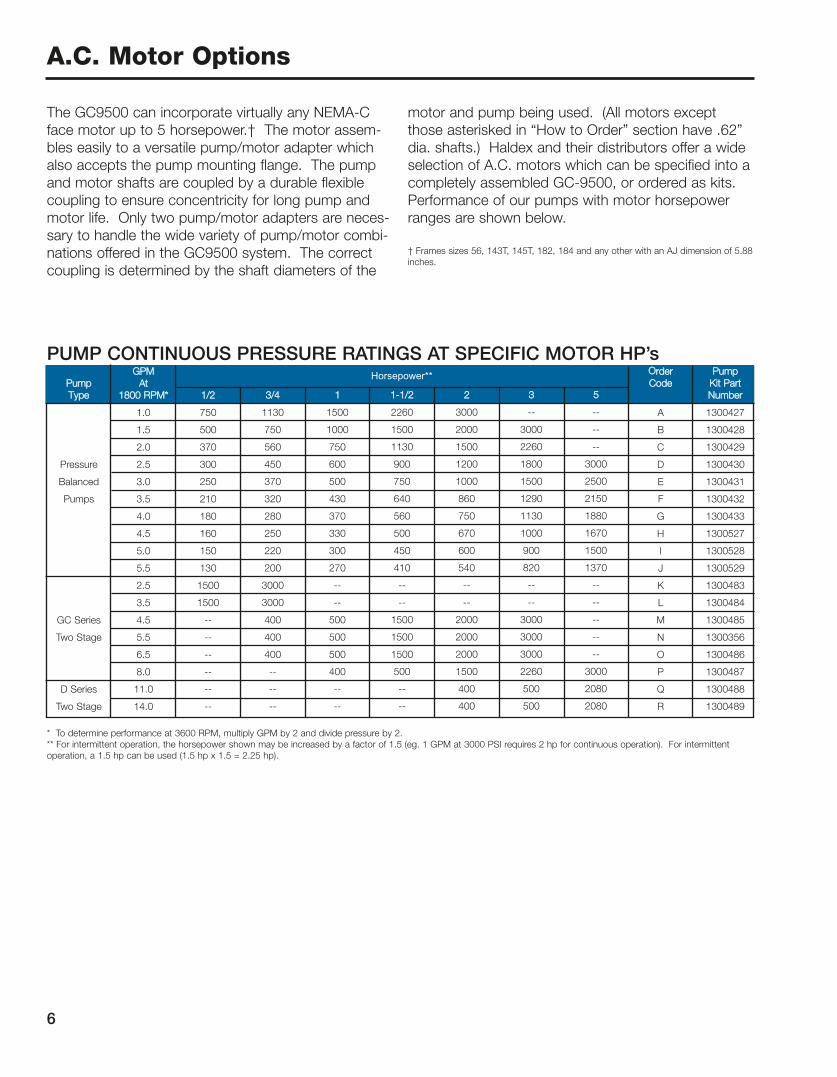
The GC9500 can incorporate virtually any NEMA-Cface motor up to 5 horsepower.† The motor assem-bles easily to a versatile pump/motor adapter whichalso accepts the pump mounting flange. The pumpand motor shafts are coupled by a durable flexiblecoupling to ensure concentricity for long pump andmotor life. Only two pump/motor adapters are neces-sary to handle the wide variety of pump/motor combi-nations offered in the GC9500 system. The correctcoupling is determined by the shaft diameters of the
motor and pump being used. (All motors exceptthose asterisked in “How to Order” section have .62”dia. shafts.) Haldex and their distributors offer a wideselection of A.C. motors which can be specified into acompletely assembled GC-9500, or ordered as kits.Performance of our pumps with motor horsepowerranges are shown below.
† Frames sizes 56, 143T, 145T, 182, 184 and any other with an AJ dimension of 5.88inches.
PUMP CONTINUOUS PRESSURE RATINGS AT SPECIFIC MOTOR HP’s
* To determine performance at 3600 RPM, multiply GPM by 2 and divide pressure by 2.** For intermittent operation, the horsepower shown may be increased by a factor of 1.5 (eg. 1 GPM at 3000 PSI requires 2 hp for continuous operation). For intermittentoperation, a 1.5 hp can be used (1.5 hp x 1.5 = 2.25 hp).
Horsepower**PPuummppTTyyppee
Pressure
Balanced
Pumps
GC Series
Two Stage
D Series
Two Stage
GGPPMMAAtt
11880000 RRPPMM**
1.0
1.5
2.0
2.5
3.0
3.5
4.0
4.5
5.0
5.5
2.5
3.5
4.5
5.5
6.5
8.0
11.0
14.0
11//22
750
500
370
300
250
210
180
160
150
130
1500
1500
--
--
--
--
--
--
33//44
1130
750
560
450
370
320
280
250
220
200
3000
3000
400
400
400
--
--
--
11
1500
1000
750
600
500
430
370
330
300
270
--
--
500
500
500
400
--
--
11--11//22
2260
1500
1130
900
750
640
560
500
450
410
--
--
1500
1500
1500
500
--
--
22
3000
2000
1500
1200
1000
860
750
670
600
540
--
--
2000
2000
2000
1500
400
400
33
--
3000
2260
1800
1500
1290
1130
1000
900
820
--
--
3000
3000
3000
2260
500
500
55
--
--
--
3000
2500
2150
1880
1670
1500
1370
--
--
--
--
--
3000
2080
2080
OOrrddeerr CCooddee
A
B
C
D
E
F
G
H
I
J
K
L
M
N
O
P
Q
R
PPuummpp KKiitt PPaarrttNNuummbbeerr
1300427
1300428
1300429
1300430
1300431
1300432
1300433
1300527
1300528
1300529
1300483
1300484
1300485
1300356
1300486
1300487
1300488
1300489

Size
1/2 Hp
3/4 Hp
1 Hp
1-1/2 Hp
2 Hp
3 Hp
5 Hp
Max.F
10.562”
10.437”
10.562”
12.187”
12.375”
12.187”
12.375”
Max.G
7.875”
7.875”
7.875”
7.875”
7.875”
7.875”
7.875”
For 0-6 GPMManifold
For 7-20 GPMManifold
For 0-6 GPMBulkheadFittings
For 7-20 GPMBulkheadFittings
OrderingCode
1
2
3
4
KitP/N
1300530
1300531
1300610
1300611
7
GC-9500 power systems are available with 5, 10, 15 and20 gallon reservoirs. These reservoirs are made of cold-rolled steel and incorporate a sight gauge, a ferrous contaminant collector and an easily accessible drain plug.Each reservoir is gasketed for reliable sealing and the 10,15 and 20 gallon units are raised off the floor to reducevibration and enhance cooling. When selecting a reservoir, be sure to select the proper reservoir coverbased on the flow rate of the selected pump. A key feature of the GC-9500 is that one reservoir cover will fitall 4 reservoir sizes. In addition, the GC-9500 can beordered with a 10 micron spin-on type return line filterwith 15 PSI bypass.
Reservoir Options
RESERVOIR COVERS
MOTORS (ALL MAX. DIM.*)
Size
5 gal.
10 gal.
15 gal.
20 gal.
A
11.25”
16.75”
23.75”
31.75”
B
11.25”
12.62”
12.62”
12.62”
C
12.00”
17.75”
24.75”
32.75”
D
12.00”
14.00”
14.00”
14.00”
E
13.50”
14.50”
14.50”
14.50”
OrderCode
A
B
C
D
KitP/N
1300387
1300388
1300389
1300390
RESERVOIRS (ALL MAX. DIM.*)
* All are max. dimensions. Contact factory for specificmotor/reservoir dimensions.
RESERVOIR DIMENSIONS

Dry Pressure Gauge
Glycerine Pressure Gauge
No Gauge
†Gauge Hardware (supply own gauge)
Control Bases/Interfaces
8
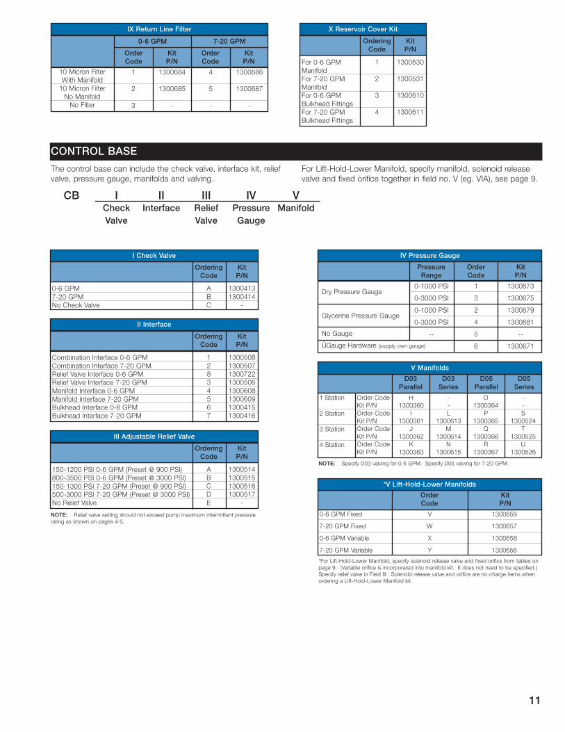
CONTROL BASES/INTERFACESThe GC-9500 can be specified with a wide variety of con-trol bases. These modular bases are assembled right onthe reservoir cover and range in complexity from simplebulkhead fittings to a four station manifold with relief valveblock, pressure gauge, and in-line check valve. Reliefvalve settings range from 0 - 3600 PSI.
To specify a control base, first determine the output flowof the pump being used. Then determine the interfacerequired based on that flow. An interface is the hardwareused to mount the valve configuration required. If a reliefvalve and directional valves are required, a combinationinterface is used. If a relief valve only is required, a reliefvalve interface is used. *If directional valves only arerequired, a manifold interface is used. If no valving isrequired, a bulkhead interface is used.
Both combination and relief valve interfaces incorporategauge ports to accept a 2.5” dry or glycerine-filled pres-sure gauge. All hardware required to assemble the inter-face is included in each individual kit.
NOTE: All of the above control base configurations canbe specified with one of two in-line check valves whichare sized based on pump output flow.
* The relief valve is not included in the interface.
After determining the correct interface, complete the con-trol base by selecting the manifold (if required) to acceptthe necessary directional control valves. Two basic mani-folds are available in multiple stations with circuits inseries or parallel. Manifolds with circuits in parallel areavailable in one to four station configurations and mani-folds with circuits in series are available in two, three, andfour section configurations. See page 11, Field V for kitpart numbers.
D03 Relief Valve Manifold
D03 Relief Valve Manifold
D03 Directional Control Valve
Manifold
D05 Directional Control Valve
Manifold
Lift-Hold-Lower Manifolds
(0-6 GPM)
Lift-Hold-Lower Manifolds
(7-20 GPM)
9/16-18 SAE
7/8-14 SAE
9/16-18 SAE
34-16 SAE
9/16-18 SAE
7/8-14 SAE
MANIFOLD PORTING SIZES
PRESSURE GAUGES
0-1000 PSI
0-3000 PSI
0-1000 PSI
0-3000 PSI
--
1
3
2
4
5
6
1300673
1300675
1300679
1300681
--
1300671
PressureRange
OrderCode
KitP/N
*Other gauges available -- Contact factory.† 1/4 NPT connector
INTERFACE KITS
1
8
4
6
1300508
1300722
1300608
1300415
2
3
5
7
1300507
130506
1300609
1300416
Combination Interface
Relief Valve Interface
Manifold Interface
Bulkhead Interface
OrderCode
KitP/N
OrderCode
KitP/N
0-6 GPM 7-20 GPM

0-6 gpm
7-20 gpm
OrderCode
V
W
ManifoldKit P/N
1300659
1300657
0-6 gpm
7-20 gpm
OrderCode
X
Y
ManifoldKit P/N
1300658
1300656
9
LIFT-HOLD-LOWER MANIFOLDSFour standard manifolds for lift-hold-lower circuits areavailable. These manifolds include cartridge, relief, checkand flow control valves as well as a solenoid release valvefor remote control of the lift-hold-lower function.
and Valve Options
LIFT-HOLD-LOWER CIRCUITS
LIFT-HOLD-LOWER MANIFOLDS
SOLENOID RELEASE VALVES FORLIFT-HOLD-LOWER MANIFOLDS
Voltages
12 VDC
24 VDC
115 VAC
230 VAC
1
2
3
4
1300725
1300726
1300723
1300724
5
6
7
8
1300667
1300668
1300669
1300670
0-6 GPM
Order Code Kit P/N7-20 GPM
Order Code Kit P/N
FIXED ORIFICES FOR LIFT-HOLD-LOWER MANIFOLDS
OrderCode
Kit P/N
A
1300660
B
1300661
C
1300662
D
1300663
E
1300664
F
1300665
1 GPM 2 GPM 3 GPM 4 GPM 5 GPM 6 GPM
NOTE: Solenoid release valve and orifice kits are no-charge items when ordering alift-hold-lower manifold kit.

OrderingCode
A
B
KitP/N
1300384
1300640
TEFCOpen Drip ProofExplosion Proof
No Motor
OrderingCode
TOXZ
For 0-6 GPMFor 7-20 GPM
KitP/N
1300572 1300573
OrderingCode
AB
For PressureBalanced PumpFor GC Two Stage PumpFor GC Two StagePump W/Inlet TubeFor D Series Two Stage Pump
KitP/N
1300480
1300641
1300642
1300643
OrderingCode
1
2
3
4
PressureBalanced Pumps
.129 cu. in. displ.
.194 cu. in. displ.
.258 cu. in. displ.
.323 cu. in. displ.
.388 cu. in. displ.
.453 cu. in. displ.
.517 cu. in. displ.
.581 cu. in. displ.
.647 cu. in. displ.
.711 cu. in. displ.
Two StageHigh Low Pumps
.259/.065 cu. in. displ.GC Two Stage Pumps.388/.065 cu. in. displ.GC Two Stage Pumps.388/.194 cu. in. displ.GC Two Stage Pumps.517/.194 cu. in. displ.GC Two Stage Pumps.646/.194 cu. in. displ.GC Two Stage Pumps.776/.259 cu. in. displ.GC Two Stage Pumps.930/.465 cu. in. displ.D Two Stage Pumps
1.395/.465 cu. in. displ.D Two Stage Pumps
OrderingCode
ABCDEFGHIJ
K
L
M
N
O
P
Q
R
How to Order GC-9500 Power Systems
10
The modular GC 9500 system may be ordered four ways depend-ing on your requirements. It may be ordered completely assem-bled, partially assembled and in complete or partial kits. Whenordering a complete or partially assembled GC 9500 power sys-tems, utilize the ordering code designations assigned to eachcomponent or sub-assembly shown below. When ordering acomplete or partial set of kits, utilize the seven digit part numberassigned to each kit.
Sepcify the GC 9500 system in two parts. First specify the powerunit which will include the pump, motor type, motor code, adapter,coupling, inlet piping, outlet hose, reservoir, return line filter andreservoir cover. Then specify the control base and valving options.The control base includes the check valve, interface, relief valve,pressure gauge and manifold.
POWER UNIT
95 IPump
IIInlet
Piping
IIIOutletHose
IVMotorType
VMotorCode
VIAdapter
VIICoupling
VIIIReservoir
IXReturn
LineFilter
XReservoir
Cover
I Pump Options
II Inlet Piping
IV Motor Type
1121314151122232425213233343531424344454152535455536*4637*47*
13004381300439130044013004411300533130044213004431300444130044513005341300446130044713004481300449130053513004501300451130045213004541300453130045513004561300457130045813005361300490130049113004921300493
1121314151122232425213233343531424344454152535455536*4637*-
1300544130054513005461300547130054813005491300550130055113005521300553130055413005551300556130055713005581300559130056013005611300562130056313005641300565130056613005671300568130056913005701300571
-
11213141511222324252132333435314243444*54*--
3545*55*-
46*--
13004631300464130046513004661300603130046713004681300469130047013006041300471130047213004731300474130060513004751300494130047613004771300606
-
130047813004791300607
-1300495
--
OrderCode
KitP/N
OrderCode
KitP/N
OrderCode
KitP/N
V Motor Code
EXPLOSIONPROOF Motors
1/2 HP, 1725 RPM, 115/230, 1 PH, 60 Hz.1/2 HP, 3450 RPM, 115/230, 1 PH, 60 Hz.1/2 HP, 1725 RPM, 230/480, 3 PH, 60 Hz.1/2 HP, 3450 RPM, 230/480, 3 PH, 60 Hz.1/2 HP, 1725 RPM, 575, 3 PH, 60 Hz.3/4 HP, 1725 RPM, 115/230, 1 PH, 60 Hz.3/4 HP, 3450 RPM, 115/230, 1 PH, 60 Hz.3/4 HP, 1725 RPM, 230/480, 3 PH, 60 Hz.3/4 HP, 3450 RPM, 230/480, 3 PH, 60 Hz.3/4 HP, 1725 RPM, 575, 3 PH, 60 Hz.1 HP, 1725 RPM, 115/230, 1 PH, 60 Hz.1 HP, 3450 RPM, 115/230, 1 PH, 60 Hz.1 HP, 1725 RPM, 230/480, 3 PH, 60 Hz.1 HP, 3450 RPM, 230/480, 3 PH, 60 Hz.1 HP, 1725 RPM, 575, 3 PH, 60 Hz.1-1/2 HP, 1725 RPM, 115/230, 1 PH, 60 Hz.1-1/2 HP, 3450 RPM, 115/230, 1 PH, 60 Hz.1-1/2 HP, 1725 RPM, 230/480, 3 PH, 60 Hz.1-1/2 HP, 3450 RPM, 230/480, 3 PH, 60 Hz.1-1/2 HP, 1725 RPM, 575, 3 PH, 60 Hz.2 HP, 1725 RPM, 115/230, 1 PH, 60 Hz.2 HP, 3450 RPM, 115/230, 1 PH, 60 Hz.2 HP, 1725 RPM, 230/480, 3 PH, 60 Hz.2 HP, 3450 RPM, 230/480, 3 PH, 60 Hz.2 HP, 1725 RPM, 575, 3 PH, 60 Hz.3 HP, 1725 RPM, 230/480, 3 PH, 60 Hz.3 HP, 3450 RPM, 230/480, 3 PH, 60 Hz.5 HP, 1725 RPM, 230/480, 3 PH, 60 Hz.5 HP, 3450 RPM, 230/480, 3 PH, 60 Hz.*.88 Dia. Shaft. All others have .62 Dia. Shaft.
OPEN DRIPPROOF Motors
TEFC Motors
.62”
.62”
.62”
.88”
.88”
.88”
.50”
.56”
.62”
.50”
.56”
.62”
123456
130063913003911300392130063813003931300394
MotorShaft Dia.
PumpShaft Dia.
OrderingCode
KitP/N
KitP/N
1300427130042813004291300430130043113004321300433130052713005281300529
1300483
1300484
1300485
1300356
1300486
1300487
1300488
1300489
KitP/N
1300387130038813003891300390
5 Gal. Capacity10 Gal. Capacity15 Gal. Capacity20 Gal. Capacity
OrderingCode
ABCD
For Four (4) BoltPumpFor Two (2) BoltA Pump
III Outlet Hoses
VII Coupling
VI Adapter Kit VIII Reservoir Kit
Some items are not available in small quantities, please contactfactory for quotation.
laurieb
Line
laurieb
Line
laurieb
Text Box
Explosion Proof Motors no longer available from stock.
lêÇÉê`çÇÉ
háí mLk
aMPm~ê~ääÉä
aMP pÉêáÉë
aMRm~ê~ääÉä
aMRpÉêáÉë
MJS dmjTJOM dmjkç `ÜÉÅâ s~äîÉ
cçê MJS dmjj~åáÑçäÇcçê TJOM dmjj~åáÑçäÇcçê MJS dmj_ìäâÜÉ~Ç cáííáåÖëcçê TJOM dmj_ìäâÜÉ~Ç cáííáåÖë
MJS dmj TJOM dmj
N
O
P
NPMMSUQ
NPMMSUR
J
Q
R
J
NPMMSUS
NPMMSUT
J
lêÇÉê`çÇÉ
háímLk
lêÇÉê`çÇÉ
háímLk
aêó mêÉëëìêÉ d~ìÖÉ
däóÅÉêáåÉ mêÉëëìêÉ d~ìÖÉ
kç d~ìÖÉ
§d~ìÖÉ e~êÇï~êÉ Eëìééäó çïå Ö~ìÖÉF
MJNMMM mpf
MJPMMM mpf
MJNMMM mpf
MJPMMM mpf
JJ
N
P
O
Q
R
S
NPMMSTP
NPMMSTR
NPMMSTV
NPMMSUN
JJ
NPMMSTN
mêÉëëìêÉo~åÖÉ
lêÇÉê`çÇÉ
háímLk
`çãÄáå~íáçå fåíÉêÑ~ÅÉ MJS dmj`çãÄáå~íáçå fåíÉêÑ~ÅÉ TJOM dmjoÉäáÉÑ s~äîÉ fåíÉêÑ~ÅÉ MJS dmjoÉäáÉÑ s~äîÉ fåíÉêÑ~ÅÉ TJOM dmjj~åáÑçäÇ fåíÉêÑ~ÅÉ MJS dmjj~åáÑçäÇ fåíÉêÑ~ÅÉ TJOM dmj_ìäâÜÉ~Ç fåíÉêÑ~ÅÉ MJS dmj_ìäâÜÉ~Ç fåíÉêÑ~ÅÉ TJOM dmj
háímLk
NPMMRPM
NPMMRPN
NPMMSNM
NPMMSNN
lêÇÉêáåÖ`çÇÉ
N
O
P
Q
NN
u oÉëÉêîçáê `çîÉê háífu oÉíìêå iáåÉ cáäíÉê
NM jáÅêçå cáäíÉêtáíÜ j~åáÑçäÇNM jáÅêçå cáäíÉêkç j~åáÑçäÇkç cáäíÉê
`lkqoli _^pb
`_ f`ÜÉÅâs~äîÉ
fffåíÉêÑ~ÅÉ
fffoÉäáÉÑs~äîÉ
fsmêÉëëìêÉd~ìÖÉ
sj~åáÑçäÇ
háímLk
NPMMQNPNPMMQNQ
J
lêÇÉêáåÖ`çÇÉ
^_`
f `ÜÉÅâ s~äîÉ
qÜÉ Åçåíêçä Ä~ëÉ Å~å áåÅäìÇÉ íÜÉ ÅÜÉÅâ î~äîÉI áåíÉêÑ~ÅÉ âáíI êÉäáÉÑî~äîÉI éêÉëëìêÉ Ö~ìÖÉI ã~åáÑçäÇë ~åÇ î~äîáåÖK
cçê iáÑíJeçäÇJiçïÉê j~åáÑçäÇI ëéÉÅáÑó ã~åáÑçäÇI ëçäÉåçáÇ êÉäÉ~ëÉî~äîÉ ~åÇ ÑáñÉÇ çêáÑáÅÉ íçÖÉíÜÉê áå ÑáÉäÇ åçK s EÉÖK sf^FI ëÉÉ é~ÖÉ VK
háímLk
NPMMRMUNPMMRMTNPMMTOONPMMRMSNPMMSMUNPMMSMVNPMMQNRNPMMQNS
lêÇÉêáåÖ`çÇÉ
NOUPQRST
ff fåíÉêÑ~ÅÉ
NRMJNOMM mpf MJS dmj EmêÉëÉí ] VMM mpfFUMMJPRMM mpf MJS dmj EmêÉëÉí ] PMMM mpfFNRMJNPMM mpf TJOM dmj EmêÉëÉí ] VMM mpfFRMMJPMMM mpf TJOM dmj EmêÉëÉí ] PMMM mpfFkç oÉäáÉÑ s~äîÉ
háímLk
NPMMRNQNPMMRNRNPMMRNSNPMMRNT
J
lêÇÉêáåÖ`çÇÉ
^_`ab
fff ^Çàìëí~ÄäÉ oÉäáÉÑ s~äîÉ
klqbW oÉäáÉÑ î~äîÉ ëÉííáåÖ ëÜçìäÇ åçí ÉñÅÉÉÇ éìãé ã~ñáãìã áåíÉêãáííÉåí éêÉëëìêÉê~íáåÖ ~ë ëÜçïå çå é~ÖÉë QJRK
fs mêÉëëìêÉ d~ìÖÉ
N pí~íáçå
O pí~íáçå
P pí~íáçå
Q pí~íáçå
lêÇÉê `çÇÉháí mLklêÇÉê `çÇÉháí mLklêÇÉê `çÇÉháí mLklêÇÉê `çÇÉháí mLk
eNPMMPSM
fNPMMPSN
gNPMMPSO
hNPMMPSP
JJi
NPMMSNPj
NPMMSNQk
NPMMSNR
lNPMMPSQ
mNPMMPSR
nNPMMPSS
oNPMMPST
JJp
NPMMROQq
NPMMRORr
NPMMROS
s j~åáÑçäÇë
klqbW péÉÅáÑó aMP î~äîáåÖ Ñçê MJS dmjK péÉÅáÑó aMR î~äîáåÖ Ñçê TJOM dmjK
MJS dmj cáñÉÇ
TJOM dmj cáñÉÇ
MJS dmj s~êá~ÄäÉ
TJOM dmj s~êá~ÄäÉ
s
t
u
v
NPMMSRV
NPMMSRT
NPMMSRU
NPMMSRS
Gs iáÑíJeçäÇJiçïÉê j~åáÑçäÇë
Gcçê iáÑíJeçäÇJiçïÉê j~åáÑçäÇI ëéÉÅáÑó ëçäÉåçáÇ êÉäÉ~ëÉ î~äîÉ ~åÇ ÑáñÉÇ çêáÑáÅÉ Ñêçã í~ÄäÉë çåé~ÖÉ VK Es~êá~ÄäÉ çêáÑáÅÉ áë áåÅçêéçê~íÉÇ áåíç ã~åáÑçäÇ âáíK fí ÇçÉë åçí åÉÉÇ íç ÄÉ ëéÉÅáÑáÉÇKFpéÉÅáÑó êÉäáÉÑ î~äîÉ áå cáÉäÇ fffK pçäÉåçáÇ êÉäÉ~ëÉ î~äîÉ ~åÇ çêáÑáÅÉ ~êÉ åçJÅÜ~êÖÉ áíÉãë ïÜÉåçêÇÉêáåÖ ~ iáÑíJeçäÇJiçïÉê j~åáÑçäÇ âáíK
Haldex (www.haldex.com),headquartered in Stockholm,Sweden, is a provider of
proprietary and innovative solutions to theglobal vehicle industry, with focus on products in vehicles that enhance safety,environment and vehicle dynamics. Haldexis listed on the Stockholm Stock Exchangeand has annual sales of nearly 7 billion SEKwith 4,400 employees. The right to modification for technical improvements is reserved. Printed in USA.
GC9500 1/06
PRODUCT RANGE
He Power Packs12/24/48 VDC 0.8 - 3.5 kW and 0.75- 3 kW AC modular power packs
Pressure Switches5 - 350 bar connecting /disconnecting
He Classic Power Packs12/24/48 VDC modular powerpacks in weatherproof boxes
W100 Hydraulic Pumps0.5 - 2.0 cc/section, 227 bar
W300 Hydraulic Pumps0.8 - 5.7 cc/section, 230 bar
W600 Hydraulic Pumps4 - 12 cc/section, 276 bar
WM600 Hydraulic Motors4 - 12 cc/section, 276 bar
W900 Hydraulic Pumps5 - 31 cc/section, 276 bar
WM900 Hydraulic Motors5 - 31 cc/section, 276 bar
WQ900 The Quiet Pump5 - 27 cc/section, 230 bar
W1500 Hydraulic Pumps19 - 50 cc/section, 276 bar
WM1500 Hydraulic Motors19 - 50 cc/section, 276 bar
G25 Hydraulic Pumps23 - 87 cc/section, 250 bar
GM25 Hydraulic Motors23 - 87 cc/section, 250 bar
GPA Internal Gear Pumps1.7 - 63 cc/section, 100 bar
GC Hydraulic Pumps/Fluid Motors1.06 - 11.65 cc/section, 276 bar
II-Stage Hydraulic Pumps4.2 - 22.8 cc/section, 276 bar
Rotary Flow Dividers3.8 - 13.3 cc/section, 300 bar
D Hydraulic Pumps3.8 - 22.9 cc/section, 207 bar
H Hydraulic Pumps9.8 - 39.4 cc/section, 207 bar
G20/G30 Hydraulic Pumps23 - 161 cc/section, 276 bar
GM20/GM30 Hydraulic Motors23 - 161 cc/section, 276 bar
G20/G30 (LS) Hydraulic Pumps23 - 161 cc/section, 276 bar
Transmission Pumps
Fuel Pumps
www.hbus.haldex.com
Haldex Hydraulics Corp.2222 15th StreetROCKFORD, IL 61104USATel: +1-815 398 4400Fax: +1-815 398 5977E-mail: [email protected]
Haldex Hydraulics Corp.214 James Farm RoadSTATESVILLE, NC 28625USATel: +1-704 873 2587Fax: +1-704 878 0530E-mail: [email protected]
Haldex Hydraulics ABBox 95SE-280 40 SK. FAGERHULTSwedenTel: +46-433 32400Fax: +46-433 30546E-mail: [email protected]
Haldex Hydraulics ABNymarsta Grand 6SE-195 30 MÅRTSASwedenTel: +46-8 591 288 50Fax: +46-8 591 288 60E-mail: [email protected]
Haldex Hydraulics GmbHPostfach 1507D-95014 HOFGermanyTel: +49-9281 895-0Fax: +49-9281 87133E-mail: [email protected]