GC(05)/INF/41 - Small power reactor projects of the United ...
88
International Atomic Energy Agency General Conference GC(V)/INF/41 28 September 1961 GENERAL Distr. Original: ENGLISH Fifth regular session SMALL POWER REACTOR PROJECTS OF THE UNITED STATES ATOMIC ENERGY COMMISSION Information gathered as a result of the United States offer inviting the Agency's participation TABLE OF CONTENTS Section List of abbreviations I. INTRODUCTION II. INFORMATION CONCERNING THE PROJECTS AS A WHOLE A. General B. Management of the projects C. Interest of the utilities in the projects D. Operating staff and training E. Nuclear superheat III. THE ELK RIVER POWER REACTOR A. General B. Important design features C. Safety D. Fuel cycle E. Construction experience F. Cost data G. Operating personnel and training H. Integration of the reactor in the utility system I. Selected references Paragraphs 1 - 9 - 9 - 18 - 37 - 40 - 47 - 54 - 54 - 57 - 72 - 88 - 107 - 121 - 130 - 138 - 8 53 17 36 39 46 53 143 56 71 87 106 120 129 137 142 143 Pages 4-5 7-8 9-16 9 - 10 10 - 13 13 13 - 15 15 - 16 17 - 31 17 17 - 19 19 - 21 21 - 23 24 - 26 26 - 28 28 - 30 30 31
Transcript of GC(05)/INF/41 - Small power reactor projects of the United ...

International Atomic Energy Agency
General Conference
GC(V)/INF/41 28 September 1961 GENERAL Distr .
Original: ENGLISH
Fifth regular session
SMALL POWER REACTOR PROJECTS OF THE UNITED STATES ATOMIC ENERGY COMMISSION
Information gathered as a result of the United States offer inviting the Agency's participation
TABLE OF CONTENTS
Section
List of abbreviations
I. INTRODUCTION
II. INFORMATION CONCERNING THE PROJECTS AS A WHOLE
A. General
B. Management of the projects
C. Interest of the utilities in the projects
D. Operating staff and training
E. Nuclear superheat
III. THE ELK RIVER POWER REACTOR
A. General
B. Important design features
C. Safety
D. Fuel cycle
E. Construction experience
F . Cost data
G. Operating personnel and training
H. Integration of the reactor in the utility system
I. Selected references
Paragraphs
1 -
9 -
9 -
18 -
37 -
40 -
47 -
54 -
54 -
57 -
72 -
88 -
107 -
121 -
130 -
138 -
8
53
17
36
39
46
53
143
56
71
87
106
120
129
137
142
143
Pages
4 - 5
7 - 8
9-16
9 - 10
10 - 13
13
13 - 15
15 - 16
17 - 31
17
17 - 19
19 - 21
21 - 23
24 - 26
26 - 28
28 - 30
30
31

GC(V)/INF/41 page 2
Section
IV.
V.
VI.
VII.
THE PIQUA NUCLEAR POWER FACILITY
A.
B .
C.
D.
E .
F .
G.
H.
I.
General
Important design features
Safety
Operating personnel and training
Construction experience
Fuel cycle
Cost data
Integration of the reactor in the utility system
Selected references
THE BONUS POWER REACTOR
A.
B .
C.
D.
E .
F .
G.
H.
General
Important design features
Safety
Operating personnel and training
Construction experience
Fuel cycle
Cost data
Selected references
THE PATHFINDER POWER REACTOR
A.
B .
C.
D.
E .
F .
G.
General
Important design features
Safety
Fuel cycle
Cost data
Operating personnel and training
Selected references
THE SMALL-SIZE PRESSURIZED WATER POWER REACTOR
A.
B .
C.
D.
E .
F .
General
Selection of the size and type of reactor
Important design features
Difficulties in the selection of the site
Present position
Selected references
Paragraphs
144 - 237
144 - -145
146 - 175
176 - 199
200 - 208
209 - 212
213 - 221
222 - 227
228 - 236
237
238 - 288
238 - 239
240 - 258
259 - 274
275 - 278
279 - 280
281 - 286
287
288
289 - 342
289 - 293
294 - 303
304 - 314
315 - 329
330 - 331
332 - 341
342
343 - 361
343
344 - 349
350 - 352
353 - 357
358 - 360
361

Section
VIII. THE EXPERIMENTAL LOW-POWER PROCESS HEAT REACTOR
A. General
B. Summary of technical aspects
Paragraphs
362 - 368
362 - 363
364 - 368
GC(V)/INF/41 page 3
Pages
71
71
71
ANNEXES
ANNEX I
ANNEX II
ANNEX III
ANNEX IV
Important design features of the Elk River power reactor
Important design features of the Piqua nuclear power facility-Important design features of the BONUS power reactor
Important design features of the Pathfinder power reactor
FIGURES
FIGURE 1
FIGURE 2
FIGURE 3
FIGURE 4
Schematic flow diagram of the Elk River power reactor
Schematic flow diagram of the Piqua nuclear power facility
Simplified schematic diagram of the BONUS power reactor
Schematic diagram of the Pathfinder power reactor
GC(V)/INF/41 page 4
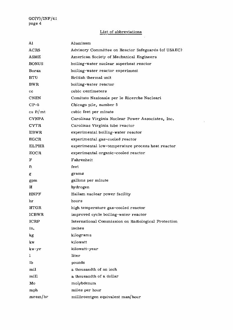
List of abbreviations
Al
ACRS
ASME
BONUS
Borax
BTU
BWR
cc
CNEN
CP-5
cu ft/mt
CVNPA
CVTR
EBWR
EGCR
ELPHR
EOCR
F
ft
g
gpm
H
HNPF
hr
HTGR
ICBWR
ICRP
in.
kg
kw
kw-yr
1
lb
mil
mill
Mo
mph
m r e m / h r
Aluminum
Advisory Committee on Reactor Safeguards (of USAEC)
American Society of Mechanical Engineers
boiling-water nuclear superheat reactor
boiling-water reactor experiment
British thermal unit
boiling-water reactor
cubic centimeters
Comitato Nazionale per le Ricerche Nucleari
Chicago pile, number 5
cubic feet per minute
Carolinas Virginia Nuclear Power Associates, Inc.
Carolinas Virginia tube reactor
experimental boiling-water reactor
experimental gas-cooled reactor
experimental low-temperature process heat reactor
experimental organic-cooled reactor
Fahrenheit
feet
grams
gallons per minute
hydrogen
Hallam nuclear power facility
hours
high temperature gas-cooled reactor
improved cycle boiling-water reactor
International Commission on Radiological Protection
inches
kilograms
kilowatt
kilowatt-year
liter
pounds
a thousandth of an inch
a thousandth of a dollar
molybdenum
miles per hour
milliroentgen equivalent man/hour

GC(V)/INF/41 page 5
mt
MTU
Mwd
Mwe
Mwth
NSPC
OMR
OMRE
PNPF
PRWRA
psia
psig
PWR
r
RCPA
rem
rep
sec
SGR
Si
SL-1
sq
SRE
SS
SSPWR
t
Th
U
USAEC
VBWR
VESR
yr
Zr
minute
metric ton uranium
Megawatt day-
Megawatt electrical
Megawatt thermal
Northern States Power Company-
organic-moderated reactor
organic-moderated reactor experiment
Piqua nuclear power facility
Puerto Rico Water Resources Authority
pound per square inch absolute
pound per square inch gauge
pressurized water reactor
roentgen
Rural Cooperative Power Association
roentgen equivalent man
roentgen equivalent physical
second
sodium graphite reactor
silicon
stationary low power reactor , number 1
square
sodium reactor experiment
stainless steel
small-size pressurized water reactor
ton
thorium
uranium
United States Atomic Energy Commission
Vallecitos boiling-water reactor
Vallecitos experimental superheat reactor
year
zirconium
NOTE
Except where otherwise stated all sums of money are expressed in United States currency.

GC(V)/INF/41 page 7
I. INTRODUCTION
1. As part of its activities in connection with the development of nuclear power, and in response to the resolutions adopted by the General Conference [1 ] , the Agency has been undertaking a continuing study of the technology and economics of small and medium sized power reactors , particularly with reference to the needs of the less-developed countries. The information gathered as a re_sult of the opportunity afforded by the United States of America to follow the development of some of the small power reactor projects in that country [2 ] is summarized in this report .
2. In discussions with officials of USAEC for the purpose of working out a program that would enable the Agency to make the best use of the offer by the United States Government, the Secretariat indicated that it was interested in obtaining essential data on the following:
(a) The Elk River 22 Mwe boiling-water reactor with a coal-fired superheater;
(b) The Piqua 11.4 Mwe organic-moderated reactor;
(c) The BONUS 16.2 Mwe boiling-water reactor with integral superheat;
(d) The Pathfinder 62 Mwe boiling-water reactor with integral superheat;
(e) The SSPWR 20 Mwe pressurized-water reactor; and
(f) The ELPHR 40 Mwth pressurized-water reactor for process heat and desalinization.
3. The Agency also expressed a desire to be kept informed about the progress of cer tain other projects such as the Hallam nuclear power facility (HNPF), the high temperature gas-cooled reactor (HTGR) at Philadelphia, and the improved cycle boiling-water reactor (ICBWR) at Michigan.
4. On each of the reactor projects listed above, information was requested from USAEC on the following:
(a) Basic design features with emphasis on design objectives;
(b) Construction experience;
(c) Safety of reactors (design, siting, containment, hazard reports);
(d) Fuel cycle (fabrication of fuel elements, fuel handling, fuel management and shipping for reprocessing);
(e) Training of the operating staff;
(f) Start-up;
(g) Cost data;
(h) Operation and maintenance experience; and
(i) Integration of the nuclear plant within the existing power network.
5. It was decided that the Agency's staff would first study all available reports on the projects and then gather further information on matters not covered by the reports but of special interest to Member States. This is being done by two staff members of the Secretariat who visit at appropriate intervals the reactor sites and hold discussions with the officials of USAEC responsible for directing the projects, and with reactor designers and manufacturers, building and construction contractors, and representatives of utility companies.
[1 ] GC(II)/RES/27, GC(III)/RES/57 and GC(IV)/RES/86.
[2 ] See also document GC(V)/161.

GC(V)/INF/41 page 8
6. It was recognized that because of differences in the time schedules for the completion of individual projects, their execution as a whole would be spread over three to four years and at any particular time during that period the Agency would be particularly interested in these projects which were then at an active stage of development.
7. The present report deals mainly with the Elk River, BONUS, Piqua and Pathfinder projects, and briefly with some others. It is mostly concerned with a discussion of basic design features, safety, experience in construction, training of personnel, and the cost, operation and maintenance of the reac tors . A list of selected references has been provided in each case.
8. USAEC has extended the fullest co-operation to the Agency's staff; reactor designers and the utility companies concerned have also been most helpful in providing necessary information. In order to carry out the program more effectively USAEC has designated a project officer for the transmittal of technical information and relevant material who is directly in touch with a counterpart in the Secretariat.
GC(V) / INF/41 page 9
H. INFORMATION CONCERNING THE PROJECTS AS A WHOLE
A. G e n e r a l
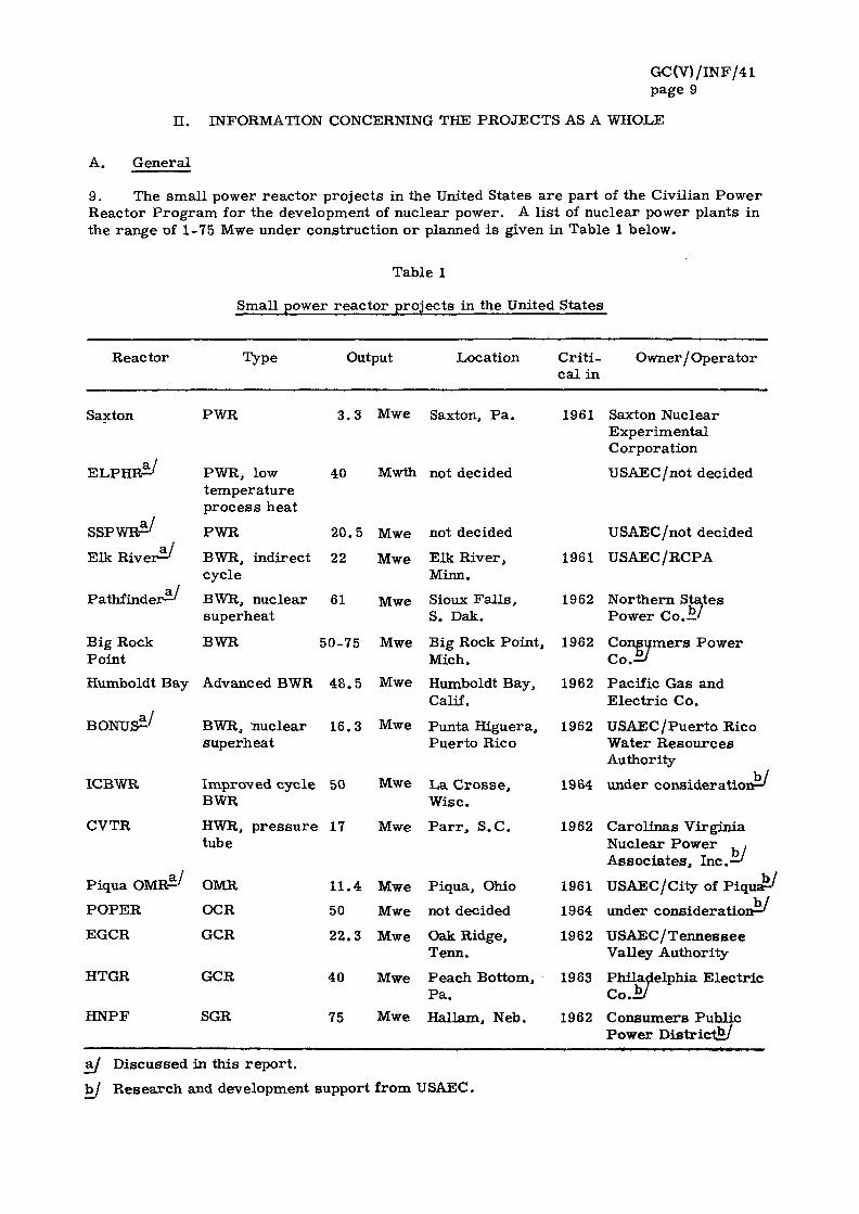
9. The s m a l l power r e a c t o r p ro j ec t s in the United States a r e pa r t of the Civil ian P o w e r Reac to r Program, for the development of nuc lea r power . A l i s t of nuc lea r power plants in the r a n g e of 1-75 Mwe under cons t ruc t ion o r planned i s given in Tab le 1 below.
Table 1
Smal l power r e a c t o r p ro jec t s in the United Sta tes
Reac to r Type Output Locat ion C r i t i - O w n e r / O p e r a t o r c a l in
Saxton PWR 3 . 3 Mwe Saxton, P a .
W& ELP:
S S P W B ^
Elk R i v e r ^
P a t h f i n d e r ^
Big Rock Point
PWR, low 40 t e m p e r a t u r e p r o c e s s hea t
PWR 20 .5
BWR, ind i rec t 22 cyc le
BWR, nuc lea r 61 superhea t
BWR 50-75
Humboldt Bay Advanced BWR 48 .5
BONUS^/ BWR, nuc lea r 16 .3 supe rhea t
Mwth not decided
Mwe not decided
Mwe Elk R ive r , Minn.
Mwe Sioux F a l l s , S. Dak.
Mwe Big Rock Poin t , Mich.
Mwe Humboldt Bay, Calif.
Mwe Punta Higuera , P u e r t o Rico
ICBWR
CVTR
Improved cyc l e 50 Mwe L a C r o s s e , BWR Wise .
HWR, p r e s s u r e 17 Mwe P a r r , S . C . tube
W Piqua OMR- ' OMR
P O P E R OCR
11 .4 Mwe Piqua , Ohio
50 Mwe not decided
1961 Saxton Nuclear E x p e r i m e n t a l Corpora t ion
USAEC/not dec ided
USAEC/not decided
1961 USAEC/RCPA
1962 Nor the rn Sta tes Power Co. ! ! /
1962 C o n s u m e r s P o w e r
1962 Paci f ic Gas and E l e c t r i c Co .
1962 U S A E C / P u e r t o Rico Water R e s o u r c e s Authori ty
1964 under consideration—^
1962 Ca ro l i na s Vi rg in ia Nuc lea r P o w e r , , A s s o c i a t e s , Inc.—'
1961 USAEC/City of P i q u a ^
1964 under consideration—'
EGCR
HTGR
H N P F
GCR
GCR
SGR
2 2 . 3
40
75
Mwe
Mwe
Mwe
Oak Ridge, Tenn.
P e a c h Bot tom, P a .
Hal lam, Neb .
1962
1963
1962
U S A E C / T e n n e s s e e Valley Author i ty
Phi lade lphia E l e c t r i c C o . * /
C o n s u m e r s Publ ic P o w e r District**/
&j D i scussed in th i s r e p o r t .
b / R e s e a r c h and development suppor t f rom USAEC.
GC(V) /INF/41 page 10
10. The small power reactor projects have two main objectives. As experimental r e actors , the plants provide basic technical data needed for large power plants and, as power producers optimized for small s izes, they furnish information on the extent to which such plants can be competitive with conventional plants in high fuel cost areas in the country.
11. Before constructing a large nuclear power plant, it is preferable to build a small sized prototype or an experimental reactor to obtain the necessary data on design and operating characteris t ics . Such plants cost much less and yield most of the information needed. For instance, the Dresden reactor was preceded by EBWR, Borax-1 - 4 and VBWK; HNPF by SRE; and PNPF by OMRE. Now, Borax-5, BONUS and Pathfinder are under construction and will lead to large sized nuclear superheat reactors .
12. Small power reactors are not always just a step towards the construction of bigger ones. In some cases such as that of the Elk River plant, where they are to be integrated into a power system, they a re built for that purpose and a re optimized for commercial power production.
13. In the United States the incentive to achieve competitive power from small nuclear plants stems from the need of a large number of small public utilities some of which are run as rura l co-operatives. They enjoy the benefits of very low interest rates and if any of these utilities is in a high-fuel-cost area, then the combination of these factors offers a promising situation for the use of a small nuclear plant. There are some similarit ies between the situation that is faced by rural co-operatives in the United States and the power companies in some of the less-developed countries in as much as both have systems with small units, low load factors and low capital charges. USAEC feels that the experience gained in the technology and economics of small plants in the United States can be of considerable benefit to these developing countries in which fuel costs a re high and where such plants could be of use.
14. Each USAEC power reactor project has specific and well-defined objectives which are determined before a decision is made to go ahead with the construction. For instance the Elk River project is for the purpose of studying thoria-urania fuel; BONUS is for studying nuclear superheat. Sometimes USAEC builds the reactors at one of its research centers - Borax-1 - 5 and EBWR at Argonne, EGCR at Oak Ridge.
15. In certain instances, experimental power reactors are built by private manufacturers under contract with USAEC. An instance is that of SRE (sodium reactor experiment), which was built at Santa Susana, California, by Atomics International. Some power reactors are built in co-operation with utility companies; USAEC pays for the reactor and retains its ownership, while the utility provides among other things the site and turbogenerator, and buys the steam at an agreed ra te . In this category fall such projects as the Elk River, Piqua and BONUS.
16. For some other projects USAEC provides the necessary funds for research and development and may even supply the fuel free of charge during a certain period, but the reactor is built and owned by a private utility company. The Pathfinder is such an example. In such cases USAEC has the right to receive all the design and operating information developed through the project.
17. Lastly, there a r e some privately owned reactors which do not have any financial support from USAEC. These include the Dresden and the Saxton plants.
B . Management of the projects
18. The proper management of a reactor project is of special importance. As in the case of any industrial plant it helps to reduce construction time and total cost and ensures adherence to the desired specifications; in the case of nuclear plants, however, additional care is necessary to assure that the installation is safe and the design and construction is according to established regulations. It is not enough, for instance, to select a contractor for a turn-key job and leave the entire responsibility to him.

GC(V)/INF/41 page 11
19. In the United States a typical power reactor project usually involves three par t ies , namely the reactor supplier, the utility company and USAEC. The reactor designer and manufacturer may also be the prime contractor employing a number of sub-contractors. His organization usually consists of a project engineer in charge of co-ordinating all technical matters including design, engineering and fabrication; an officer in charge of the implementation of contracts and a resident construction engineer who supervises the work at the si te.
20. The utility company, which is the customer, has its own separate organization, consisting of the contract officer and a reactor plant manager supported by a group of technical men. The contract officer handles all negotiations for revisions and changes in the contracts and looks after the interests of the customer in the implementation of the agreement with the prime contractor.
21. The reactor plant manager, who is usually selected ahead of t ime, is assisted by a group of engineers and operators who will ultimately take, over the plant and run it . This group must follow all the necessary technical details of the design and construction of the plant and learn the operating techniques. Sometimes it may be desirable to seek outside advice from an architect-engineer or firm of consulting engineers to ensure that the plant meets all the requirements of the utility company. The customer also has to make the necessary arrangements for the training of the operating staff in co-operation with the r e actor supplier. Another important responsibility of the utility is to have an effective public relations program to educate and inform the population in the area .
22. USAEC is particularly concerned with the safety of the plant. As the national regulating and licensing authority it approves the site, construction and operation of the plant according to its safety cr i ter ia . Where USAEC also owns the plant or provides part of the finances, its responsibilities are proportionately greater . For instance, it handles the Elk River project through its field office known as the Operations Office, which adminis ters and co-ordinates all activities in connection with a USAEC reactor project and works closely with the reactor designer, building and construction contractor, the utility company and local and state authorities. Its job is to ensure that all objectives of the project are fulfilled, specifications met, schedules adhered to, and above all that the plant meets the safety standards established by USAEC. The Operations Office has various divisions which actively participate in the implementation of the project. Usually, a project coordinator is designated for each project who is in close touch with all the divisions of the Operations Office, the contractor and the utility and provides guidance and co-ordination for the speedy and satisfactory completion of the project. There is also a site represent ative from this office who follows the progress of work on the spot and reports to the Operations Office.
23. The Reactor Engineering Division i s responsible for the programing of all technical activities (excluding construction) for placing the reactor in operation, and for a continuing technical evaluation of reactor operation and performance. The Contracts Division has primary responsibility for the administration of the prime contracts with the design and operating contractors and for co-ordination of all matters concerning these contracts. The Engineering and Construction Division has primary responsibility for the administration of construction contracts and for the co-ordination of all matters concerning them. The Health and Safety Division develops and recommends safety policies and procedures and undertakes the safety review with which the Operations Office is charged.
24. The safety problems of a reactor project a re of paramount importance and a summary of the main tasks carr ied out, in collaboration with the reactor designer and the utility company, as a part of the safety evaluation of a typical power reactor installation is given in paragraphs 25 to 36 below.

GC(V>/INF/41 page 12
25. Site location and description. To site a reactor, necessary data on hydrology, geology, climatology, meteorology, seismology, topography, ecology, population and industrial density must be collected because of their effect on construction, effluent control, reactor operations and safety. These data a re also needed for the preliminary hazards summary report .
26. Public relations and information. The construction of a reactor near a community ra i ses many questions and it is essential to educate and inform the public so that it is not perturbed by rumors about radiation hazards. Through local civic organizations, the population has to be fully informed of all relevant facts concerning the plant and the measures taken to ensure its safe operation.
27. Preliminary hazards summary report . The preparation of this report should star t when the conceptual design ends. It has to include in addition to the information mentioned in paragraph 25 above, a description of the reactor, the auxiliary systems, the facilities, the housing, and an analysis of the possible hazards. Although this report has to be p re pared by the reactor designer, the Operations Office plays an important advisory role . It gives an outline of the subjects which should be discussed, reviews the draft and suggests revision, wherever necessary. The report is then usually sent to the Reactor Hazards Evaluation Branch of USAEC at Washington through the Division of Reactor Developments, which makes its own comments, and further improves it before presenting it to the Advisory Committee on Reactor Safeguards (ACRS) for approval. The construction of the reactor cannot s tar t unless the site has been favorably reviewed by this Committee.
28. Pre-operational environmental monitoring program. While the reactor is being built, a complete survey of the radiation levels and of the soil and vegetation in the area has to be carr ied out so that the ambient conditions a re fully established, and any departures from these, after the reactor start-up, can be observed. This requires the preparation of a monitoring plan, the fixing of sample points, the collection and analysis of samples, etc. The Operations Office works with the utility to organize this program.
29. Radiological physics. A health physicist has to be hired by the utility well in advance (about two years) of the date on which the reactor is expected to be cri t ical . He sets up the health physics laboratory, prepares the health physics operating manual, and helps to give training in radiation protection. The Operations Office advises in the selection of the man and the organization of the health physics program.
30. Safety and fire protection. The design and construction of the buildings and facilities a re reviewed by the Operations Office, in consultation with the contractors, to ensure compliance with the safety and fire codes.
31. Reactor operators training program. This program is initiated about two years before the reactor becomes cri t ical . The reactor designer is responsible for this program but receives much help and advice from the Operations Office, in the selection of personnel, selection of courses to be held, and the training to be imparted. The Operations Office also reviews the operating manual, and makes arrangements for the Division of Licensing and Regulations to hold the operators licensing examination for supervisory and operating personnel.
32. Final hazards summary report . This report contains the final description of the facility emphasis being laid on those features which result from changes in the preliminary design. It also gives details of the administration, the organization, the plans and the procedures concerning the project, and a final estimate of the potential radiation hazard from the maximum credible accident. The final hazards summary report has to be completed at least four months in advance of s tar t-up. As in the case of the preliminary hazards summary report , the Operations Office advises on i ts contents and reviews it before forwarding it to the Division of Reactor Development for further action. ACRS has to approve the report before permission is granted to make the reactor crit ical . For cer tain reactors the review by ACRS is followed by open public hearings.

GC(V) /INF/41 page 13
33. Operating manual and emergency procedures. This is prepared by the designer in consultation with the Operations Office.
34. Initial criticality. The procedures for start-up and fuel management (handling, loading and unloading) a re prepared by the designer and reviewed by the Operations Office.
35. Environmental monitoring. The pre-operational environmental monitoring program is reviewed with the assistance of the utility concerned and arrangements a re made for a continued monitoring survey to keep a check on any increases in the radiation level in the surrounding area.
36. Continued safety review program. To ensure that the reactor is operated safely and in accordance with the approved procedures, a reactor safety review committee is constituted by the contractor. This committee carr ies out a pre-operational review and inspection of the reactor and evaluates the operating procedures and the influence of any significant changes in the system. After full power has been achieved, the Operations Office conducts periodic surveys for safety and fire protection, radiological physics, and reactor operational safety.
C. Interest of the utilities in the projects
37. Utilities, operating as co-operatives and serving in small municipalities, have evinced great interest in the future of small nuclear power plants. They feel that there is a strong justification for devoting much effort to the development of units in the range of 20 - 75 Mwe capable of producing power at competitive pr ices . According to them, there are not many utilities in the United States that could use large size power reactors in the 300 Mwe range. On the other hand, there are hundreds of smaller utilities which have a great need for smaller plants.
38. The experience of the utilities now building reactor plants indicates that great importance should be attached to contractual arrangements and negotiations in connection with a power reactor . Because of the far-reaching implications in building such plants, a great deal of legal and administrative work has to be done, the extent of which is not generally recognized in the beginning. Sufficient funds should be earmarked for this purpose.
39. With regard to the integration of the nuclear plant, the utilities tend to treat the r e actors in the same way as a conventional station. For instance, in one case, it is planned to use the same operating staff for conventional and nuclear units on the same s i te . They are receiving training in the handling of nuclear plants, and will then pass the required licensing examination after which they will run the conventional as well as the nuclear units. This approach is based upon a desire on the part of the utilities to reduce the operating expenses to a minimum. In any case, it is necessary for USAEC to approve the staffing plan of the reactor station.
D. Operating staff and training
40. After the essential safety requirements have been incorporated in the design of a reactor, the proper and safe operation of the plant is in the hands of the operating personnel. USAEC exercises great care in the selection and training of the reactor staff so as to reduce to a minimum the possibility of an accident because of an operator 's e r r o r . Although a large number of reactors have already been put into operation in the United States, no standardized training program for operators has been evolved. This is perhaps due to the fact that every reactor system has its special features and requirements which do not lend themselves to a common approach. Moreover, operating experience of the various types is not sufficient to enable the establishment of rules which would be applicable in all cases .
GC(V) /INF/41 page 14
4 1 . The present approach, therefore, is to find individual solutions to the problem of staffing each reactor . For instance, in the case of the Dresden, Yankee and Indian Point reac tors , the companies concerned developed special training programs for their personnel in consultation with USAEC. For the projects under direct USAEC control, some operators are recruited from among staff already trained at various s i tes , while others come from utilities, and are given necessary theoretical and practical training. It may be mentioned that the reactors operations course at Oak Kidge and the operators training schemes at Shippingport have proved to be very useful, although the number of the persons thus trained is not sufficient to meet the requirements of the reactor projects now under way.
42. USAEC insists that for each reactor plant a detailed operating manual be prepared to cover all situations. This manual is a part of the final hazards summary report and has to be duly approved. USAEC representatives also visit the reactor sites unannounced to se,e if all the rules are being fully observed. Should they notice anything contrary to provisions of the license, the operation of the facility can be suspended until corrective action has been taken.
43. The operating staff for a reactor plant can be divided into three main categories, namely:
(a) Operators;
(b) Supervisors; and
(c) Specialists.
Some of the basic qualifications of each of these, together with their training programs, a re discussed in paragraphs 44 to 46 below.
44. Operators. In the case of those reactors the licensing of which is subject to public hearings, operators are required to obtain a license which is granted by USAEC after a thorough theoretical and practical examination given at the reactor si te. A power reactor operator must have at least a high school diploma, and in addition it is desirable that he should have several years ' operating experience in a conventional or nuclear power plant. He should have an aptitude for physics, mathematics and technology. It is considered preferable not to employ persons with an advanced degree because they may have a tendency to depart from the established operating procedures. Moreover, the job is too much of a routine to hold their interest for long.
45. Supervisors. The supervisors should be senior persons with long experience in running and managing a conventional or nuclear power plant. They should have received advanced theoretical and practical training in all problems relating to operation and safety of the reactor . The plant manager in particular should have training in health physics so that he fully understands the importance of the health and safety regulations which must be observed by all persons working in the plant.
46. Specialists. Finally, specialists a r e needed to provide the following essential services:
(a) Health physics services
It is most desirable for the health physicist to have basic training in radiological physics together with practical experience with a reactor health physics group. He should also have a good knowledge of instruments used for measurements and detection of radiation. The health physicist should be assisted by at least one technician to help in radiation surveys and monitoring, and to keep a complete record of the exposures received by the staff. He should be a high school graduate with some training in a reactor plant;

GC(V)/INF/41 page 15
(b) Reactor safety and fuel handling and management
The presence of nuclear fuel, whether inside or outside a reactor , presents many special problems which should be looked after by a well qualified and responsible person. He should be particularly familiar with criticality hazards connected with fuel storage. He can also carry out fuel management and account for the fissionable material going in and out of the plant;
(c) Instrumentation, repai rs and maintenance
The recruitment of qualified instrumentation men poses a rea l problem. There a re relatively few people available who a r e familiar with the use of pulse circuits , counters, detectors and other equipment associated with the electronics and control of a reactor . If an experienced man is not available, a good electronics man can be selected and given at least a year" s training in the types of instruments and controls used in the plant; and
(d) Chemical analysis
The control of the quality of water or organic liquid going into the reactor and the analysis of reactor wastes is very important for the safe and proper operation of the plant. This requires an experienced chemical analyst. For general maintenance of the plant, it is preferable to s tar t with a person having experience in similar work in a conventional plant. He should receive on-the-job training at the power reactor, and indoctrination in the principles of radiation protection.
E . Nuclear superheat
47. General. A considerable amount of work i s being done in the United States of America, the Union of Soviet Socialist Republics, the Federal Republic of Germany and Japan on the development of nuclear superheat reactors in which there is now a growing interest . These reactors can be of various types such as the graphite or D2O moderated pressure tube type; the non-integral boiling-water type having two separate cores , one for boiling and the other for superheating; and the integral type, using only one core with one zone for boiling and the other for superheating.
48. Four nuclear superheat power reactors a re currently under construction in the United States, namely the Borax-5 at Argonne, Idaho; the Pathfinder at Sioux Fal ls , South Dakota; BONUS at Punta Higuera, Puerto Rico; and the Vallecitos experimental superheat reactor (VESR) at San Jose, California.
49. The Borax-5 is a flexible reactor which is expected to be ready by the end of 1961 and will be used to test various nuclear superheat concepts using different core a r rangements and to study the stability of boiling reactors at high power densities. VESR which is expected to be in operation by June 1962, i s a steam-cooled flexible test-bed capable of testing a large number of superheated fuel elements. It will get its steam supply from a separate conventional boiler or from the Vallecitos boiling-water reactor (VBWR). The Pathfinder and BONUS reac tors a re full scale integral superheat power plants and a r e discussed in detail in this report .
50. Besides the above mentioned reactors several conceptional design studies on large sized nuclear superheat reac tors a re being undertaken. These cover integral and non-integral (steam-cooled) types including mixed spectrum and Zr-H moderated reac to r s .
GC(V)/INF/41 page 16
51. Incentive for nuclear superheat. The basic incentive for nuclear superheat is economic. Water reactors which produce low temperature saturated steam require, at p resent, large specially-made turbines which a re costly and not very efficient. If reactors can produce superheated steam at high pressures , smaller and more economical turbogenerators of the standard type - which are to be preferred - can be used in the power plants. This will lead to a gain in plant efficiency that could be increased to 40% and could be comparable with that of the most efficient conventional stations. The result will be savings in nuclear fuel, reduction in piping and pumping requirements, and other auxiliary services, and a lowering of the cost of containment. The total savings in generation costs for a large plant may be about 0.5 mill/kwh for future plants, which is equal to about 7 - 10% of the generating costs for water reactors without superheat.
52. Major problems. Although nuclear superheat reactors hold forth the promise of cheaper nuclear power, there are a number of technical problems which must still be solved. All the design problems associated with the boiling-water reactors have to be overcome, in addition to those associated with nuclear superheat itself. An integral superheat reactor, for instance, exhibits the characteristics of a boiling-water reactor (in the boiling region) and a gas-cooled reactor (in the superheater region) and, as such, inherits the problems of both.
53. Some of the basic problems concerning nuclear superheat a re :
(a) Fuel element. The success of nuclear superheat is largely dependent on the development of a satisfactory fuel element having long-term integrity and designed with due regard to neutron economy and net costs . This fuel element must be capable of achieving high burn-ups under the severe temperature and pressure conditions characteristic of a nuclear superheater;
(b) Radioactivity. Since the superheated steam will be used directly, the amount of radioactive material carried over to the turbine and condenser should be within tolerable l imits . The corrosion of highly active stainless steel fuel cladding and of the surfaces is a matter of particular concern. The residue resulting from evaporation of the moisture contained in the steam and its deposition on the fuel elements in the superheat should be kept to a minimum;
(c) Operational safety.
(i) The potential hazards associated with the flooding and unflooding of the superheater section should be avoided;
(ii) The proper power distribution between the boiling and superheating regions must be maintained without introducing other problems such as intolerable hot spots and instability; and
(iii) Adequate shut-down cooling for the nuclear superheater elements must be guaranteed even if the flow of steam to the turbine is interrupted; and
(d) Materials. It is essential to develop alloys and materials for fuel cladding and for the superheater section having good mechanical strength at high temperatures and pressures , resistance to radiation damage and corrosion, and good heat transfer propert ies.
GC(V)/INF/41 page 17
III. THE ELK RIVER POWER REACTOR
A. General
54. The Elk River reactor is a natural circulation, indirect cycle, boiling-water reactor having a thermal output of 58 Mw, supplemented by 14 Mw from a coal-fired superheater, to give a net electrical output of 22 Mwe. This reactor has been built as a part of the power demonstration program of USAEC to gather practical experience on the operation and cost of this type of plant as a source of power for base load operation in a grid.
55. The reactor is located next to an existing steam plant of the Rural Co-operative Power Association of Elk River, Minnesota (RCPA), which is a small utility serving a population of 60 000. The contract between RCPA and USAEC stipulates that RCPA will furnish the turbogenerator facilities and the site, whereas all expenses in connection with the reactor will be borne by USAEC. RCPA will operate the reactor for USAEC and purchase the steam generated from the reactor at a rate which is comparable with the cost of power from its conventional stations. After five years of operation, RCPA has the option to purchase the reactor.
56. The prime contractor for the reactor is Allis-Chalmers Manufacturing Company, which is responsible for the design, engineering, construction, s tart-up and test operation of the reactor and associated plant, and training of the operating personnel. The work is being performed on a cost type contract with a maximum ceiling and a fixed fee. The formal contract was signed in June 1958 and construction began in August 1958.
B. Important design features
57. A summary of important data concerning the reactor is set out in Annex I, and a schematic diagram of the reactor system is shown in Figure 1.
58. Objectives. The object of building this reactor is not to advance boiling-water reactor technology as such, but by keeping the design innovations to a minimum, to construct a plant which will operate with maximum reliability and safety and continuously supply power to a small utility system. Elk River reactor is essentially a modified version of EBWR, with the same basic design features. The essence of its design is simplicity and safety. The distinguishing feature of this reactor is the fuel which, unlike that of EBWR, consists of a mixture of 4. 3% enriched UO2 (Urania) and Th02 (Thoria) in the form of pellets contained in stainless steel tubes. It is one of the first commercial nuclear power plants to use a urania-thoria mixture although samples of this type of fuel have already been tested successfully in EBWR core. The experience gained in this type of fuel cycle will greatly add to the know-how in the use of thorium as a fuel, and several countries which have large deposits of thorium will watch with interest the results obtained.
59. The reactor operates on an indirect cycle using an intermediate heat exchanger so as to eliminate the carry-over of any radioactivity into the turbine. This is a very conservative approach because it has already been demonstrated that the transfer of steam from the reactor directly into the turbine does not pose any significant hazard. Nevertheless, an intermediate heat exchanger has been added, as an extra precaution.
60. A coal-fired superheater is used to improve the quality of the secondary steam to 825°F in order to permit the use of a preferred standard efficiency turbine. The over-al l effect of the use of the superheater will be a lowering of generating costs.
61. The stability of the reactor has been assured by having a relatively low average power density of 39. 6 kw/l of the coolant, and a high pressure of 936 psia, as opposed to Borax and EBWR, which have proved to be stable at higher power densities and lower pressures . Borax-4 had a power density of 67. 5 kw/l and a pressure of 300 psig. The corresponding values for EBWR were 65 kw/l and 600 psig.
GC(V)/INF/41 page 18
62. The plant has been designed for eventual operation at twice the initial power level by using forced circulation. Thus, the containment shell, reactor vessel, shielding, heat transfer equipment, emergency condenser and other permanent fixtures are designed for 116 Mwth. Space has also been provided for the installation of an additional steam generator, sub-coolers and other auxiliary equipment.
63. Core. The reactor core is a cylinder approximately 5 ft. in diameter and 5 ft. high. It contains 148 fuel elements with room for 16 more. It has 13 cruciform-type control rods. Water entering at the bottom at 450 F moves up by natural convection through the reactor core as it becomes heated and leaves the reactor in the form of steam at 536°F.
64. P ressure vessel. The pressure vessel is a 7 ft. diameter cylinder 25 ft. high with a removable elliptical head having four 12 in. nozzles. It is made of 3 in. thick grade B carbon steel as base metal, with a 304 stainless steel internal cladding of 0. 109 in. thickness, capable of withstanding a design pressure of 1250 psig with a margin of safety of four. In designing the number of steam outlets and water inlets, provisions have been made for doubling the output of the reactor with forced circulation.
65. Shielding. A combination of a 3. 75 in. lead and steel thermal shield with an 8.5 ft. ordinary concrete having a density of 2. 4 g/cc is used for biological shield to reduce the activity around the reactor to less than 2.5 mrem/hr at 116 Mwth. Provisions have been made for stacking additional 1 ft. concrete shielding, if necessary, around the reactor . At 58 Mwth operation it is not necessary to shield the primary system piping.
66. Containment shell. The reactor containment shell serves the purpose of containing any release of fissionable material from the reactor in case of an accident. It houses the reactor, steam generator and other auxiliary equipment associated with the nuclear plant. The reactor control room and turbogenerator are located outside the containment shell in an adjoining conventional building. Suitable gas-tight penetrations in the shell have been provided for steam pipes and cables. The cylindrical containment building, with a hemispherical top, is 115 ft. high with an internal diameter of 74 ft. and a total free volume of 287 000 cu ft. It is made of carbon silicon steel plates welded together, which have thicknesses varying from 0. 87 in. on the sides to 0. 5 in. at the top. It is lined inside with ordinary concrete of thickness varying from 2 ft. on the sides to 4 in. at the top. Outside of the shell is covered with 2 in. of insulation. Important design conditions for the containment vessel are:
(a) Maximum internal pressure of 21 psig and maximum negative pressure of .5 psig;
(b) Maximum leakage rate of . 1% of free volume per day at an internal pressure of 21 psig; and
(c) All welds with a joint efficiency of 90%.
Calculations indicate that at 116 Mwth operation pressure build-up after sudden primary system rupture and instantaneous flashing of water will be 20. 3 psig which is less than the designed value.
67. Fuel handling and storage. Fuel handling has been greatly simplified in this reactor. The loading of new fuel and unloading of spent elements is done manually under water. There is no need for a special coffin and the operation can be carried out by three persons (including a health physics technician) using simple tools. Firs t the reactor is shut down and after about eight hours for the reactor to cool, the top shield plug is removed. The steel lined cavity, which is linked with the adjoining fuel storage valve, is filled with water, and lights and viewing equipment are lowered for good visibility. The bridge which runs over rai ls is positioned over the reactor. After proper indexing, the fuel handling tool is lowered into the fuel element to be removed by a steel cable. The tool engages the fuel element securely which is then raised up and transferred via the canal to the storage area. At all t imes the fuel element remains under a minimum of 8 ft. of water. Fresh fuel elements which are kept around the storage pool are picked up and lowered into the core in a similar manner.

GC(V)/INF/41 page 19
68. Allowing about 12 hours for the reactor water to cool and make preparations for refueling, it would take about 36 hours in all to unload and reload one-third of the core. The resulting dose received by the operators carrying out fuel will not exceed the weekly tolerances. The spent fuel elements are stored on racks in the storage pit and kept under 25 to 32 ft. of water. After 120 days these fuel elements are put into a special cask the tolerance rate around which is not expected to be more than 2. 5 mrem/hr. The present indications are that the loaded cask will be transported by a truck to the processing si te.
69. Waste disposal system. The design of the Elk River reactor is such that only very small quantities of radioactive waste material should accumulate in the course of operation at full power. Since natural circulation is used instead of pumps in the primary system, there is no pump leakage. In view of this, no facilities are planned at the site for concentration and local disposal of high level radioactive waste materials . All suspect materials will be stored inside the containment vessel for batch disposal later on.
70. Radioactive primary water is not expected to leak from the system at a rate of more than three gallons a day. Two retention tanks, each with a capacity of 3 000 gallons, are provided for collecting and storing all waste water. Active material from this water is removed by passage through the purification system. Water will be discharged to the building drain system and be carr ied to the river only when prior radio chemical analysis has shown the concentration of radioactivity to be well within tolerances corresponding to one tenth of the maximum permissible concentration. Solid wastes accumulating from primary purification loop and residue filling are placed, after proper cooling, in drums to be filled with concrete. The drums can then be shipped from the site for burial.
71. The building air conditioning system filters 3 000 cu ft/mt of air continuously and after proper monitoring, it is released through an air stack, if the radioactivity is less than the permissible level.
C. Safety
72. Safety in design. Great emphasis has been placed on making this plant as safe as possible without increasing the costs beyond a reasonable limit. The Elk River reactor , like other boiling-water reactors (Borax, EBWR, VBWR, Dresden, etc. ) has a large negative void coefficient (at operating level 0. 19%=*;) which assures inherent safety against fairly rapid and reasonably large reactivity additions. However, the use of thoria-urania-ceramic fuel, with its low conductivity and large time constant, partly reduces the effectiveness of the negative void coefficient because it prevents the prompt formation of such voids. In spite of this, the steam void coefficient alone is sufficient to take care of transients with periods down to 100 milliseconds or reactivity insertions up to 0. 65%—. For rapid reactivity increases, greater than 0. 65%=£ and up to 0. 9%£&. and shorter periods, reliance has been placed on the large metal temperature coefficient which compensates for the weaker void coefficient.
73. An auxiliary boric acid injection system, that is operated manually, has been p ro vided for use in emergencies. Boric acid solution at 200°F and 2 000 psig capable of giving 2% shut-down margin with all rods out can be inserted into the core in 10 seconds.
74. In designing the reactor pressure vessel piping, primary steam generators and sub-auxiliaries, ASME codes are followed, which give a margin of safety of four between the design pressures and that required for rupture. Similar high factors of safety were used in the design of mechanical equipment in the plant.
75. Control. The control of the reactor is so arranged that all situations which require immediate remedial action to prevent a serious accident will cause an automatic shut-down. Under conditions which can lead to dangerous situations but which are not hazardous in themselves, alarm signals are used. Failure of the operator to take immediate action on these alarm signals will not result in an accident, although the operator should correct the dangerous situation as soon as possible.

GC(V)/INF/41 page 20
76. Reactivity control is obtained by 13 cruciform-type control rods and the use of boron as burnable poison in stainless steel fuel cladding. The maximum excess reactivity in the cold clean core is 12. 7%—£•, which is controlled by the negative reactivity of 13 control rods having 18. 3%—£, ana of burnable poison having 5. 8%=^, leaving a minimum net negative reactivity of 11. 4%—g for safety under all operating conditions. Even if the central control rod should fail to enter the core, the reactor would be sub-critical by at least 2. 6%^j| at all temperatures. The maximum rate of reactivity insertion due to the withdrawal of the central control rod is 0. 06%—r-.
77. Use of boron as burnable poison in fuel cladding serves two purposes. In the beginning it helps to control the excess reactivity in the core; later on, as the fuel is used up, it also burns away and partly compensates for the loss of reactivity in the fuel.
78. Also available are removable boron steel pins and spiked fuel elements enriched to 5. 2% which may be used for reactivity changes if necessary.
79. Site. The reactor is located on the site of an existing steam plant alongside a r iver near the village of Elk River (population 1 400), which is a small farm-type community. It is 30 miles from the cities of Saint Paul and Minneapolis (population 1 million). The exclusion area is 240 acres . The population distribution as a function of the distance from the reactor is shown in Table 2 below.
Table 2
Population distribution
Distance in miles Population density/sq. mile
0.25 0
0.50 60
1.00 200
5.00 2 656
10.00 7 700
80. The site is accessible by road and rai l . The surface drainage is from the reactor site towards the river and the nearest water supply intake for the City of Minneapolis is about 21 miles down river.
81. A detailed survey of the geology and hydrology of the site and the vicinity was per formed to estimate the time it would take for a large liquid spill at the reactor site to reach the river water, either by surface flow or by percolation through the ground.
82. An exhaustive meteorological analysis of the area, based upon several years of available data, was made to determine how any accidental release of activity might be spread over the surroundings.
83. Analysis of maximum credible accident. The hazards summary report for the Elk River reactor gives the detailed analysis of the possible consequences of a maximum credible accident, based upon the assumption that the 16 in. diameter water inlet pipe suddenly ruptures and the entire core is drained off in 10 seconds. Under the worst circumstances, when there is a delay of 6. 83 minutes in initiating the emergency cooling water flow from the 30 000 gallon overhead storage tank, the claddings of 8. 62% of the fuel pins might melt and release fission products.

GC(V)/INF/41 page 21
84. As a result of this rupture in the primary system and consequent steam flashing, the pressure build-up in the containment shell would be 20. 3 psig for 116 Mwth operation. This is less than the rating of the containment shell, which is 21 psig. Therefore, the leakage rate will not exceed the designed value of . 1% of the volume in 24 hours.
85. In Table 3 below is shown the direct radiation dose rate at various distances from the containment shell, which would result if all the volatile fission products and 5% of the strontium contained in the melted fuel pins were to be released.
Table 3
Elk River plant: direct radiation dose rate at various distances
Distance Total rem/f i r s t hour
200 ft. 0.692
£ mile (exclusion area) 0. 037
| mile 0.009
86. The resulting radiation effects in the surrounding area, under the worst meteorological conditions, are shown in Table 4.
Table 4
Elk River plant: integrated dose rates
Whole body Integrated iodine Strontium Distance gamma dose inhalation (dose) inhalation (dose)
rem/8 hours rem/first hour rem/first hour
200 ft. 0.87
£mi l e 0.20 28.3 0.420
(exclusion area)
| mile 0.11 8.5 0.126
1 mile 0.07 2.5 0.030
87. The normally accepted emergency doses are 25 rem for the whole body and 300 r em due to iodine inhalation. The expected doses are well below these values.
D. Fuel cycle
88. Objectives. There has been considerable interest in the use of thorium bearing fuels because of the favorable nuclear properties of U which is produced from the thorium, and recently a symposium was held on the subject [3 ] . To provide experience in such use the Elk River reactor is being fueled with a mixture of thorium and uranium with a u content of 4. 3% of the weight of uranium and thorium. Twenty-two spiked fuel assemblies containing 5.2% u ^ 5 have also been fabricated for use as a standby.
[ 3 ] Symposium on "Uranium-Thorium Cycle", CNEN, Rome, 13-15 June 1961.

GC(V)/INF/41 page 22
89. The fissile fuel content of the spent fuel can be returned to USAEC for credit. However, since the price and demand for this material must eventually be based upon the cost of its recovery and re-use in a reactor, a study has been made by the Allis-Chalmers Manufacturing Company for CNEN on the construction of a pilot plant (capacity 15 kg of fuel/day) for the processing and fabrication into fuel elements of this and similar fuels, to provide information on the economics of the cycle.
90. Fuel element design. There are 148 standard fuel elements in a core loading of the reactor . Twenty-two spiked fuel elements have also been fabricated for standby, which contain 24 spiked rods and one center standard rod. The fuel elements are 815/8 in. long, about 3^ in. square, and weigh 85 lbs. each. Each one consists of 25 stainless steel rods, 61 in. long and 0. 452 outer diameter containing about 600 parts per million of boron as a burnable poison. The center pin of a fuel bundle is interchangeable with a borated stainless steel pin. Each fuel rod is filled with 120 ceramic oxide pellets of thorium and uranium. Grid castings at the ends hold the rods in a 5 by 5 array; top and bottom fittings support and position the elements in the core, and clamps maintain the correct spacing between the rods over the length of the assembly.
91. The fuel pellets are solid right cylinders 0. 4075 _+ 0. 002 in. in diameter, with pellet faces perpendicular and parallel to within 0. 005 in. The standard fuel pellet contains 95. 4% thorium, 4. 3% U 2 3 5 and 0. 3% U 2 3 8 (4. 6% of approximately 93% of U 2 3 5 ) . The pellets may contain up to 0. 4% of a densifier such as calcium oxide or titanium oxide, replacing an equal weight of thorium oxide. The density of each pellet is a minimum of 9. 46 g/cc (94% theoretical).
92. Each rod contains a 60 + £ in. stack of fuel pellets whose total oxide fuel weight is 1226 + 10 grams, containing 46. 3 jf 0.5 grams of U 2 3 5 (1227+ 10 grams containing 56. 06 _+ 0. 56 grams U2 3^ in the case of spiked rods).
93. The seller of the fuel is not liable for the uranium use charge up to 110% of the amount of UO2 present in the fabricated fuel elements and for non-recoverable UO2 losses up to 1. 5%, but is liable for excesses above these amounts.
94. The contract warranty on the fuel elements provides for 6 700 Mwd/t of thorium and uranium peak exposure. This will result in 4 800 Mwd/t average exposure. The est i mated maximum burn-up is 28 200 Mwd/t, and theoretical average batch exposure is 8 600 Mwd/t. The expected average exposure of the fuel discharged is 9 500 Mwd/t (0. 22 atom per cent burn-up).
95. Burn-out at high heat fluxes is estimated to occur at 1 million BTU/hr-ft2 whereas the maximum expected heat flux is 313 000 BTU/hr-ft at 58 Mw of reactor power output.
96. Fuel element fabrication. Very high standards of precision are maintained in fuel fabrication. The fabrication of the fuel elements consists of four stages, namely:
(a) Fuel rod fabrication;
(b) Upper-end fitting;
(c) Lower-end fitting; and
(d) Fuel element assembly.
97. All fuel rod tubes must conform to tolerances on length, straightness, ovalness and squareness, and an eddy current test which detects irregulari t ies. Ten per cent of the tubes are given a rigorous visual examination to determine intergranular attack of the inside and outside surfaces.
GC(V)/INF/41 page 23
98. A threaded end-plug is automatically fusion -heliarc welded to the bottom of a fuel-rod tube. The weld is radiographed and leak tested at this point or after the top plug is welded to the tube. Each fuel pellet is then visually inspected (any cracks or chips exceeding 5% of the total area is a cause for rejection of the pellet), and then loaded into a tube to a length of 60 + ^ in. The tube is evacuated to 500 microns or less and then filled with 99. 9% grade helium at one atmosphere. The top threaded end-plug is then automatically fusion -heliarc welded to the fuel rod in a helium atmosphere specified previously. Two radiographs are taken of each fuel rod weld and compared with those taken simultaneously of standard defective end-plug welds (i. e. welds containing two 0. 02 in. deep radially drilled holes 120° apart, one hole being filled with lead). For radiographic inspection of the pellets in the rods, 20% of all rods are selected at random and radiographed over their full length.
99. All rods are then leak tested with a mass spectrometer helium leak detector. Any rod or assembly having a leakage of greater than 1. 5 x 10 - t ) cc/sec at 550_+_50°F over its entire length, is rejected.
100. The box for the upper-end fitting is fabricated from 304 stainless steel sheet, all seams being resistance welded. An adaptor for the fuel rods is then welded to the box with an inert-gas shielded arc . The fitting is cleaned by vapor-degreasing and rinsing in hot water followed by methyl alcohol and air-drying.
101. The transition piece, tube, and nose fitting of the lower-end fitting is also resistance welded in an inert gas, the necessary surfaces machined, and welds cleaned as above, after removal of welding scale with a stainless steel brush.
102. For the fuel element assembly, five-rod fuel element sub-assemblies are fabricated by placing five rods in a fixture that holds them in a plane with spacing clips of adjacent rods overlapping. Fuel elements are then assembled from five five-rod sub-assemblies and two 5 x 5 grids. Nuts are placed on the threaded end-plugs to hold the grid plates in place, and then tack welded. The grids of the fuel element and the end-fittings are welded together, and the welds of the final fuel assembly cleaned as previously described.
103. Fuel management. The initial loading of the reactor is 148 standard fuel elements, about 40% of which will contain borated center pins, with 22 spiked fuel elements for standby and start-up versatility. The core can accommodate 164 elements. In normal operation the reactor will be shut down for removal of spent fuel at intervals of approximately one year (12 to 15 months). The fuel handling, both loading and unloading, will be carr ied out manually under water, as has been described previously.
104. Only a third of the 148 elements having an expected exposure of 9500 Mwd/MTU will be replaced annually. They will be removed from the center of the core, elements in the outer regions will be moved in radially to the center, and new elements placed in the outer perimeter. The reactor is expected to operate about 4750 Mwd/MTU (320 days) before the boron pins must be replaced. After pin replacement the reactor is expected to operate an additional 4750 Mwd/MTU (320 days). The irradiated fuel elements will be stored in the adjacent cooling pond for 120-180 days.
105. Plans have not yet been finalized for the shipment and processing of these elements. However a contract has been negotiated for the design and fabrication of a shipping cask weighing about 30 tons which could accommodate 24 Elk River or 13 Piqua fuel elements. The expected delivery is July 1962 and the estimated cost is $85 000.
106. Consideration is being given to the processing and re-fabrication of the fuel elements in the pilot plant facility proposed for construction by CNEN. Under equilibrium conditions these elements might achieve an average exposure of 18 500 Mwd/MTU.

GC(V)/INF/41 page 24
E. Construction experience
107. The ground was broken for this plant in August 1958 and it was estimated that construction would be completed in 30 months and that the reactor would be critical by the end of 1960. In November 1960 the construction was virtually complete but the start-up had to be delayed for a number of reasons. In general no major problems were encountered in the actual construction of this plant except for the usual difficulties normally associated with any industrial or conventional power plant. The construction contractor estimates that it took about 300 000 man hours to build the plant. It would normally take 29 to 36 months to complete a reactor of the Elk River type in the United States compared with 24 to 30 months for a conventional plant of the same size. Details concerning the time schedule for the project are given in Table 5.
Table 5
Elk River plant: time schedule for the project
Item Initial estimate Actual
Start of construction Containment shell erection Reactor vessel
(fabrication and delivery) Control rod drives Reactor building Completion of construction Fuel elements delivery Initial criticality Full power testing
August 1958 January 1959
January 1959 February 1959 April 1959 November 1960 November 1960 December 1960 March 1961
August 1958 March 1959
July 1959 July 1959 August 1959 December 1960 September 1961 October 1961?^ December 196l2'
_a/ Expected.
108. The original schedule called for plant start-up by the end of 1960. Later the date was revised to March 1961. The latest estimate is that the reactor will become critical in October 1961. It appears, therefore, that the start-up has been put off by about nine months. This delay has been caused by a combination of factors including a steel strike, the redesigning of the fuel elements and their re-fabrication, and re-work on the pressure vessel and control rods. All of these problems are conventional in nature rather than nuclear. It may be pointed out that whenever any changes are made in a component of the reactor plant extensive reviews are required to ensure that the change has not affected the safety of the reactor as a whole. Such reviews or hearings, though necessary, take time and delay the completion or operation of the plant. It appears that as more experience is gained in building and operating nuclear reactors it may be possible to make certain a l terations during construction without raising any doubts about their effect on the safety of the system.
109. Some comments on certain important phases in the construction of this project are as follows:
(a) Reactor vessel
110. The delivery of the vessel was delayed by three to four weeks on account of a steel s tr ike. An X-ray examination of the nozzles indicated some cracks in one of them; it had to be sawed off and a new transition piece was welded in its place. Visual examination of the pressure vessel showed a few cracks in a section of the cladding surface. This area
GC(V)/INF/41 page 25
was grounded away to base metal and re-clad with a richer alloy, thus necessitating a review of the ability of the vessel to meet the specifications and code requirements. The review committee has reached the conclusion that the work will not affect the ability of the vessel to meet the design specifications.
111. It may be mentioned that stainless steel clad pressure vessels are also used in several industrial plants but in the case of a nuclear reactor the tolerances are closer and inspection more rigid which can lead to further work in case of doubt.
(b) Fuel elements
112. The original design of the fuel elements involved the use of grid wire for spacing the fuel rods and to ensure the mechanical stability of the assembly. This was considered unsatisfactory and replaced by straps located at between a third and two-thirds of the distance along the length of the fuel assembly. Spot welding of the straps to the fuel rods resulted in leakage under test. The new design provided for pressure clamping of the straps to the fuel rod and welding to each other instead of to the rods. The fuel element redesign, re-fabrication and consequent reviews were factors in delaying the start-up of the plant.
(c) Control rods
113. The original 17-4 PH steel control rod drives were returned for re-heat treatment in the light of experience with such drives on the Dresden reactor.
(d) Skills required
114. In general most of the skills needed for building the plant, excluding the core, were conventional and similar to those needed for an ordinary steam plant. The installation of the core components, which is high precision work, was accomplished by the engineers of the reactor designer and manufacturer.
115. The construction of the carbon steel containment shell required 15 expert welders experienced in carbon arc welding who had passed the required code tests. Five ordinary welders assisted them. The welders worked under the guidance of a superintendent, a foreman and a lead man and finished the job in seven months. All welds were X-rayed and only 10% had to be re-done.
116. Stainless steel pipe welding was carried out by six qualified welders in about six months under the direction of a supervisor and a foreman.
117. All carbon and stainless steel welds were radiographed by an X-ray man and two assistants.
118. With regard to the training of the welders, it is felt that a person with some welding experience can qualify for this work after three months of specialized training under a good instructor.
(e) Concrete pouring
119. All concrete pouring work in the plant, including shielding, containment shell lining, floors, etc. , took about eight months using on an average 35 men. Heavy concrete pouring required extra care and some persons were given on-the-job training for this purpose. This work normally takes twice the time needed for ordinary concrete pouring.

GC(V) / INF/41 page 26
(f) P r e s e n t s t a tus
120. The cons t ruc t ion of the plant has a lmos t been completed . One hundred and seven fuel e lement a s s e m b l i e s have a l ready been de l ivered to the s i te and the r e s t a r e expected by October 1961. Open public hea r ings in connection with the l icens ing of the plant m a y take p lace in September 1961. Ini t ial loading and c r i t i ca l i ty t e s t s will be c a r r i e d out a s soon as the hea r ings a r e over . P r e s e n t indicat ions a r e that the plant may become c r i t i c a l by October 1961 and full power may be r eached four to s ix months l a t e r .
F . Cost data
121. Const ruct ion . At the t ime the pro jec t was ini t ia ted, the e s t ima ted design and cons t ruc t ion cos t s for the r e a c t o r plant to be borne by USAEC w e r e $9. 4 mi l l ion . This included the cost of the s u p e r h e a t e r . As of May 1961, the total e s t ima ted projec t cos t s were ,g iven as $9. 01 mil l ion although the ac tual cost may be somewhat h igher . The b reakdown of these c o s t s i s given in Table 6.
Table 6
Elk River plant: cost breakdown
(In thousands of US do l l a r s )
Cost of m a t e r i a l s Cost of labor or „, . , I tem . t . , . , - . , . • Tota l
or equipment instal la t ion
Reac tor plant s t r u c t u r e s and s e r v i c e s 1 216 234 1 450
Reac to r equipment 1 006 36 1 042 ( con t ro l s , v e s s e l , shielding, e t c . , excluding fuel)
P r o c e s s s y s t e m 1 022 37 1 059 ( e v a p o r a t o r s , pumps , tanks , heat exchange r s , e t c . )
Superhea te r s y s t e m 734 73 807 ( s u p e r h e a t e r , s t r u c t u r e s and s e r v i c e s )
Sub-total 3 978 380 4 358
Engineer ing and design 1 034
Indi rec t and genera l project c o s t s 2 993
Sub-total 8 385
Fuel fabr icat ion (including development) 630
TOTAL 9 015
122. Excluding the fuel and fabricat ion cos t s of $630 000 but including the RCPA cost of $1 .59 mi l l ion ( s t r u c t u r e and s i te improvemen t s , tu rbogenera to r , a c c e s s o r y e l ec t r i ca l equipment , and misce l l aneous plant t r a n s m i s s i o n ) the total cost i s about $10 mil l ion. This g ives a unit capi ta l cost for the 22 Mwe plant (58. 2 and 14. 0 Mwth of nuc lear and fossi l - fuel heat r e spec t ive ly ) of $455 pe r kilowatt.
123. T h e r e is the possibi l i ty that the r e a c t o r may eventually achieve double the design power , and provis ion has been made to accommoda te the addit ional equipment which would be needed. The achievement of th is power output would significantly r educe the unit capi ta l cos t .
GC(V) / INF/41 page 27
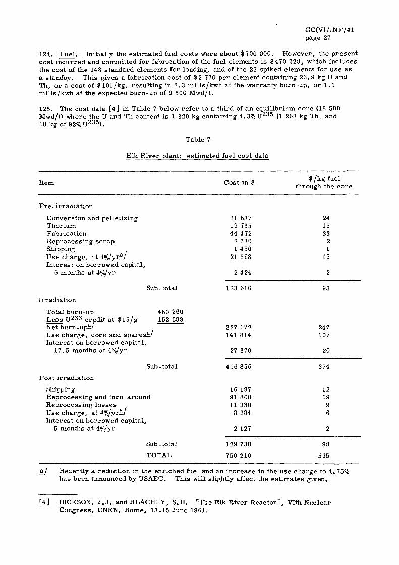
124. F u e l . Init ially the e s t ima ted fuel c o s t s w e r e about $700 000. However , the p r e s e n t cos t i n c u r r e d and committed for fabr icat ion of the fuel elements i s $470 728, which inc ludes the cos t of the 148 s t andard e lements for loading, and of the 22 spiked e l emen t s for u s e a s a s tandby. This gives a fabr ica t ion cost of $2 770 pe r e lement containing 26 .9 kg U and Th, or a cos t of $ 1 0 l / k g , r e su l t i ng in 2 .3 mi l l s /kwh at the wa r r an ty b u r n - u p , or 1.1 mi l l s / kwh at the expected b u r n - u p of 9 500 Mwd/ t .
125. The cost data [ 4 ] in Table 7 below r e f e r to a th i rd of an equi l ib r ium c o r e (18 500 Mwd/t) where the U and Th content i s 1 329 kg containing 4 . 3 % U 2 3 5 (1 268 kg Th, and 68 kg of 93% U 2 3 5 ) .
Table 7
Elk River plant: es t imated fuel cos t data
I tem r ^ o + i r , * $ / k g fuel Cost m $ ,. ' . .,
through the c o r e
P r e - i r r a d i a t i o n
Convers ion and pel le t iz ing 31 637 24 Thor ium 19 735 15 Fabr i ca t ion 44 472 33 Reprocess ing s c r a p 2 330 2 Shipping 1 450 1 Use cha rge , at 4%/yrj*/ 21 568 16 In t e r e s t on bo r rowed capital,
6 months at 4%/yr 2 424 2
Sub-total 123 616 93
I r r ad ia t ion
Tota l bu rn -up 480 260 L e s s U 2 3 3 c red i t at $ 1 5 / g 152 588 Net b u r n - u p ! ' 327 672 247 Use c h a r g e , c o r e and s p a r e s t . ' 141 814 107 In t e re s t on bo r rowed capi ta l ,
17 .5 months at 4%/yr 27 370 20
Sub-total 496 856 374
P o s t i r r ad i a t i on
Shipping 16 197 12 Rep roces s ing and t u rn - a round 91 800 69 R e p r o c e s s i n g l o s s e s 11 330 9 Use cha rge , at 4%/yrJL/ 8 284 6 I n t e r e s t on bo r rowed capi ta l ,
5 months at 4%/yr 2 127 2
496 856
16 91 11 8
197 800 330 284
Sub-tota l 129 738 98
TOTAL 750 210 565
BJ Recent ly a reduct ion in the enr iched fuel and an i n c r e a s e in the use c h a r g e to 4 . 75% h a s been announced by USAEC. This will s l ightly affect the e s t i m a t e s g iven.
[4] DICKSON, J . J . a n d B L A C H L Y , S .H. "The Elk River R e a c t o r " , Vlth Nuc lea r C o n g r e s s , CNEN, R o m e , 13-15 June 1961.

GC(V) /INF/41 page 28
126. Based upon the given nuclear core cost of $750 210 for 10 080 hours of full power operation, this yields $74/hr or 3.4 mills/kwh for the nuclear cost. Adding the cost of the coal for the superheater at $25/hr, or 1.1 mills, gives a total fuel cost of 4.5 mills/kwh.
127. It has been estimated by CNEN that their pilot plant facility would cost about $4 million, which would have a capacity about twice that required for the Elk River reactor, and that thorium bearing fuel from a reactor could be processed and re-fabricated for about $200/kg of fuel. For a fuel exposure of 20 000 Mwd/t, which is expected from this type of fuel, the generating cost would be 2 to 3 mills/kwh, which includes costs for chemical conversion, make-up of U 2 ^ , inventory and losses.
128. Operation and maintenance. No definite costs on the operation and maintenance are available although estimates have been made. An annual estimate given by the Allis-Chalmers Manufacturing Company is given in Table 8 below.
Table 8
Elk River plant: operation and maintenance costs
Item Cost in $
1 Superintendent 12 Operators
Overhead at 20% Material
Sub-total
TOTAL
10 800 86 400
97 200
19 440 30 000
146 640
The above cost is the equivalent of $6.7/kw/yr or 1.0 mills/kwh at 80%plant factor, but does not include the cost of an additional staff of about 14 persons (shift-supervisors, health physicist, maintenance personnel, etc.) which will increase the operating costs to about 2 mills/kwh.
129. The control rods may have to be replaced after one or two core lives (the initial 13 control rods cost about $90 000). Thus the replacement of the control rods may contribute 0.1 to 0. 2 mills/kwh to the cost of electricity generation.
Operating personnel and training
130. The staffing plan for the Elk River reactor is shown in Table 9.
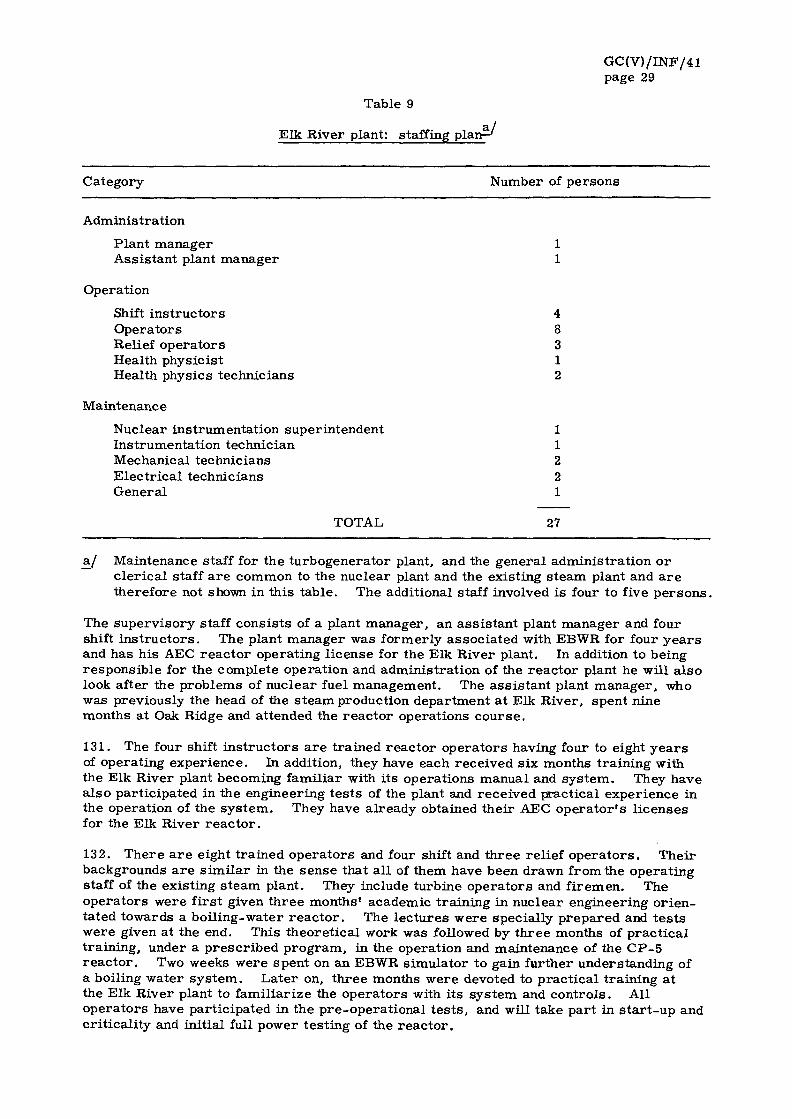
GC(V) / INF/41 page 29
Table 9
a / E lk River plant: staffing p l a n - '
Ca tegory Number of p e r s o n s
Admin is t ra t ion
P lan t manage r 1 Ass i s t an t plant m a n a g e r 1
Operat ion
Shift i n s t r u c t o r s 4 O p e r a t o r s 8 Relief o p e r a t o r s 3 Health phys ic is t 1 Health phys ics technic ians 2
Maintenance
Nuc lea r ins t rumenta t ion super in tendent 1 Ins t rumenta t ion technic ian 1 Mechanical technic ians 2 E l e c t r i c a l technic ians 2 Gene ra l 1
TOTAL, 27
aj Maintenance staff for the t u rbogene ra to r plant, and the gene ra l admin i s t r a t i on o r c l e r i c a l staff a r e common to the nuc lea r plant and the exis t ing s t e a m plant and a r e the re fo re not shown in th i s t ab le . The addit ional staff involved is four to five p e r s o n s .
The s u p e r v i s o r y staff cons i s t s of a plant manage r , an a s s i s t a n t plant manage r and four shift i n s t r u c t o r s . The plant manage r was f o r mer ly a s soc ia t ed with EBWR for four y e a r s and has h i s AEC r e a c t o r opera t ing l i cense for the Elk River plant . In addit ion to being r e spons ib l e for the comple te opera t ion and admin i s t r a t ion of the r e a c t o r plant he will a l so look after the p rob lems of nuc lea r fuel management . The a s s i s t a n t plant m a n a g e r , who was previous ly the head of the s t e a m product ion depa r tmen t a t Elk River , spent nine months at Oak Ridge and at tended the r e a c t o r opera t ions c o u r s e .
131 . The four shift i n s t r u c t o r s a r e t r a ined r e a c t o r o p e r a t o r s having four to eight y e a r s of opera t ing expe r i ence . In addit ion, they have each rece ived s ix months t r a in ing with the Elk River plant becoming fami l ia r with i t s opera t ions manua l and s y s t e m . They have a l so par t i c ipa ted in the engineer ing t e s t s of the plant and r e c e i v e d pract ica l expe r i ence in the opera t ion of the s y s t e m . They have a l r eady obtained the i r AEC o p e r a t o r ' s l i c ense s for the Elk River r e a c t o r .
132. T h e r e a r e eight t r a ined o p e r a t o r s and four shift and t h r e e re l ie f o p e r a t o r s . The i r backgrounds a r e s i m i l a r in the s e n s e that a l l of them have been drawn f rom the opera t ing staff of the exis t ing s t e a m plant . They include turb ine o p e r a t o r s and f i r emen . The o p e r a t o r s were f i r s t given t h r e e months ' academic t r a in ing in nuc lea r engineer ing o r i e n ta ted towards a bo i l ing-wa te r r e a c t o r . The l e c t u r e s w e r e spec ia l ly p r e p a r e d and t e s t s w e r e given at the end. This t heo re t i ca l work was followed by t h r e e months of p r a c t i c a l t r a in ing , under a p r e s c r i b e d p r o g r a m , in the opera t ion and main tenance of the C P - 5 r e a c t o r . Two weeks w e r e spent on an EBWR s imula to r to gain fur ther unders tand ing of a boil ing wa te r s y s t e m . L a t e r on, t h r e e months w e r e devoted to p r a c t i c a l t r a in ing at the Elk R ive r plant to f ami l i a r i ze the o p e r a t o r s with i t s s y s t e m and c o n t r o l s . All o p e r a t o r s have par t i c ipa ted in the p r e -ope ra t i ona l t e s t s , and will take p a r t in s t a r t - u p and c r i t i ca l i ty and ini t ia l full power tes t ing of the r e a c t o r .

GC(V)/INF/41 page 30
133. In the initial stages, the responsibility for the operation of the reactor will be with the prime contractor, who will give further training to the staff for a period of 60 days.
134. Before RCPA takes over the operation of the plant, USAEC will examine each of the 11 operators and assistant plant manager and award licenses to those who qualify.
135. The instrumentation superintendent has had four years experience with reactors at Hanford. He has undergone nine months special study and training to obtain a thorough understanding of the controls of this reactor . He wiH be assisted by two instrumentation men, one of which also looks after conventional power units at the si te.
136. The health physicist for the reactor is a trained radiological physicist who graduated from the University of Rochester under an AEC fellowship. He received additional t raining on the CP-5 reactor and attended various courses to become familiar with standards and procedures of reactor health physics and radiochemistry. The person acting as assistant health physicist attended a brief course in health physics and received further training at the si te. The health physics technician is receiving on-the-job training. Chemical analysis and water quality control will be carried out by the technician connected with the conventional power units at Elk River.
137. The existence of a conventional steam plant at the same location will be of considerable help. This eliminates the need for hiring extra turbine operators and maintenance men to look after the conventional equipment. Similarly, the clerical work will be performed by existing staff of the steam plant.
H. Integration of the reactor into the utility system
138. The Elk River plant is a part of the power system operated by RCPA which has an installed capacity of 70 Mw (excluding that of the nuclear plant). The peak demand of the system was 52 Mw in 1960 with a load factor of 42%. The load is growing at the rate of about 8|% per year.
139. The system is not isolated and is interconnected with four adjoining systems run by other utilities, from which it receives power in case of need. The generating costs a r e greatly influenced by the very low rate of interest (about 2%) which is available to rura l co-operatives in the United States. The fuel costs in the area are 39^ and 33̂ 1 per million BTU respectively for coal and gas. Interrupted gas supplies are available at even lower r a t e s . The average generating cost in the system is 8.4 mills/kwh and dump power is available from the adjoining systems at 4 .5 mills/kwh. The average sale price is 15.2 mills/kwh, which compares favorably with that in the surrounding a reas .
140. The addition of the nuclear plant will not increase the generating costs for RCPA, who will simply buy the steam from USAEC at a cost comparable to that of producing the steam from their own existing steam plants. The Elk River reactor will operate at base load and will be used to its full availability.
141. RCPA is very enthusiastic about the nuclear plant and is proud of the fact that it is expected to be the first small utility to use such a plant in its system. It feels that if the experience of doing so is satisfactory, the contemplated addition in the near future of 50 Mw to its capacity might be achieved by the installation of a nuclear power plant.
142. The utility company has attached great significance to an active public relations program to inform the community of the implications of installing a nuclear plant. The people in their turn have generally accepted the plant and are proud of it. After the SL-1 accident, no repercussions were noted in the Elk River a rea . There appears to be a realization that this plant has been designed with great emphasis on safety and every p re caution has been taken to protect the people from any hazards.
GC(V)/INF/41 page 31
I. Selected references
143. A list of selected references concerning the Elk River power reactor is given below:
"Project Highlight Report", covering period August 1958 - August 1961, issued monthly by Allis-Chalmers Manufacturing Company, Milwaukee, Wis.
"Preliminary Hazards Report for the RCPA Elk River Reactor at Elk River, Minnesota", Nuclear Products, ERCO, Division of ACF Industries, Inc . , Riverdale, Md. (March 1959).
RCPA - Job descriptions ERR, Rural Cooperative Power Association (June 1960).
"Allis-Chalmers Organization for Design, Preoperational Nuclear Testing of the Elk River Reactor", Allis-Chalmers Manufacturing Company, Milwaukee, Wis. (September 1960).
"Operations Manual, "Vol. I: Operating Procedures for the RCPA Elk River Reactor", Allis-Chalmers Manufacturing Company, Milwaukee, Wis. (8 July 1960).
"Operations Manual, Vol. II: Plant Specification for the RCPA Elk River Reactor", Allis-Chalmers Manufacturing Company, Milwaukee, Wis. (8 July 1960).
"Fuel Element Report - Elk River Reactor", Allis-Chalmers Manufacturing Company, Milwaukee, Wis. (September 1960).
"Final Safeguards Report - Elk River Reactor", Allis-Chalmers Manufacturing Company, Milwaukee, Wis. (April 1961).

GC(V)/INF/41 page 32
IV. THE PIQUA NUCLEAR POWER FACILITY
A. General
144. The 11.4 Mwe Piqua organic-moderated reactor is a part of USAEC's Demonstration Power Program. It is intended to extend the knowledge gained from the design, construction and operation of OMRE on the technical and economic feasibility of this type of plant under actual operating conditions of a utility system. This is the first organic-moderated power reactor to be used commercially, and will serve as a prototype of a medium size nuclear power plant. It is expected to yield very valuable data on all matters concerning such plants.
145. The reactor is located on the east bank of the Miami River and will supply steam to the Piqua Municipal Power Station, on the other side, by overhead pipes bridging the r iver . The reactor is owned by USAEC, under a contract with whom the City of Piqua has to supply the site and turbogenerator, and will also operate the plant for the first five years and purchase the steam produced by the reactor at a price to be mutually agreed upon. The plant is being built under a fixed price contract and the prime contractor for design and construction is Atomics International. Frank Messer and Co. is the building contractor.
B. Important design features
146. A summary of important data concerning the Piqua reactor is set out in Annex II, and a schematic diagram of the reactor system is shown in Figure 2.
147. Objectives. This reactor has been designed to fit into the Piqua municipal system and provide steam to an existing turbine. This consideration established the temperature and pressure conditions of the outlet steam from the reactor at 550 F and 435 psig. It is a load-following plant in the range of 20 to 100% of its rated capacity, and is capable of being fully integrated into the small system of which it is a part . In addition, it can supply processed steam to the local industries within a radius of 3 000 ft. The main consideration in the design is to use steam equipment with the minimum possible variation from the conventional type and to employ carbon steel in the primary loop.
148. The Piqua reactor has been developed on the basis of the experience gained with OMRE, which has established the technical feasibility of this type of reactor. Actual construction was preceded by two years of research and development to explore and study some additional problems connected with fuel element control, safety rods, the fuel handling system, and the various organic process systems to pave the way for the design of this reactor . The accumulated experience of the chemical processing and petroleum refining industries, which have employed organic materials as coolants under high temperature and pressure conditions, was used with great advantage. The Piqua reactor represents the next step in the development of organic reactor technology. An experimental organic reactor, the 40 Mwth EOCR, is currently under construction at the Idaho Reactor Testing Station. It is an experimental plant designed to study the behavior of fuel elements and organic coolants under high temperature and flux conditions. A 50 Mwe OMR, which will serve as a prototype for a 300 Mwe nuclear power plant, is under consideration for possible completion by 1964.
149. Interest in this type of reactor system stems from several possible advantages in using organic fluid as moderator and/or coolant in a reactor. Conventional materials and equipment such as carbon steel, pumps and valves can be used, which are cheaper and easier to handle. The reactor is inherently safe and operates at low pressure . The corrosion in the vessel core and piping due to coolant flow is negligible, and there is no danger of any chemical reaction with the cladding or uranium. A negative temperature coefficient shows good stability during load variations and the low level of coolant activity permits easy access to heat transfer components during operation.

GC(V) /INF/41 page 33
150. Among the disadvantages are the chemical decomposition of the organic fluid under radiation, and the substantial cost of make-up (58 lbs /hr at full power for Piqua). The poor heat transfer characteristics of organic fluids necessitate the use of a special type of fuel element to increase the effective heat transfer area. The organic liquids tend to leave a film deposit on the fuel element surfaces, and although this in itself does not pose any problem, if a thick deposit is formed by particulates it interferes with heat transfer and steps have to be taken to prevent it.
151. Core. The reactor core i s 4 . 8 ft. in diameter and 4.5 ft. long and consists of 85 aluminum-clad fuel elements and 13 control rods and 2 neutron sources. It is located at the bottom of the core tank and is surrounded by an annular thermal shield. Steel grid plates located above and below the core support the fuel elements and control rod. The organic moderator and coolant is an isomeric mixture of terphenyls commercially available as Santowax R. The flow through the core is maintained by forced circulation using two 6 000 gpm pumps. The heat output of the core is 45. 5 Mwth. The coolant enters the core from above at 519 F and leaves the core through the bottom plenum at 575°F. Organic fluid fills all the available space in the tank and serves as moderator, coolant, reflector and shielding for the core.
152. P ressu re vessel. The reactor vessel is made of low carbon steel and has an internal diameter of 7 ft. 8 in . , an overall height of 27 ft. 3 in . , and a thickness varying from 1 1/8 in. to 2 1/4 in. It is designed according to ASME specifications for an internal pressure of 300 psia and 750°F. The operating conditions are 120 psia and 575 F . Coolant inlet and outlet nozzles penetrate the vessel near its upper end. Six other nozzles are provided for thermo-couple leads, organic sample lines and control rod cables. The head is bolted to the vessel and sealed by a soft metal gasket. The reactor vessel is located below ground level and is supported on a ledge inside the core cavity liner, which is made of 1 in. thick mild steel. The reactor foundations are built around the cavity liner. In the event of core tank rupture, the cavity liner will serve as a secondary tank to retain the coolant at a level above the top of the reactor core.
153. Reactor heat transfer system. The organic coolant is pumped through the core at a constant rate of 5.5 x 10^ lbs/hr at all power levels. To vary the reactor output, a part of the coolant is by-passed around the boiler. Two 6 000 gpm pumps are used in parallel , which are made of carbon steel with stainless steel shafts and impellers, and are designed to minimize leakage. The coolant enters the core at 519 F and leaves at 575 F . After leaving the core, it first passes through the superheater and then the boiler. Both boiler and superheater are of the standard shell- and tube-type with double wall tube-sheet construction to facilitate leak detection. The coolant enters the superheater at 575°F and leaves at 571°F, producing 150 000 lbs /hr of steam at 550 F and 435 psia under full load conditions. After leaving the superheater, the coolant goes to the boiler where its temperature drops from 572°F to 519°F, while it generates saturated steam. It is then returned to the core to start the cycle again.
154. Shielding. Radial shielding consists of the coolant, the core tank wall which is 1.5 in. thick, a thermal shield 4 in. thick surrounding the core tank, the reactor vessel wall which is 1 1/8 in. thick, the cavity liner of 1 in. thick steel and 8 ft. of ordinary concrete which serves as the biological shield. Vertical shielding consists of the coolant, the upper grid plate, a 9 in. thick core tank head, and the top shield plug.
155. Radiation level in areas with uncontrolled access is less than . 75 m r e m / h r (1.5 r em/yr ) . This is well below the maximum permissible dose of 5 r em/y r recommended by ICRP. After one year of operation, the radiation dose rate at 1 ft. from the main heat transfer piping will be about 115 mrem/hr during full power. Thus, the radiation from plant piping will be low enough to permit limited access to the process area during plant operation. The background radiation in areas where decay tanks containing radioactive wastes are housed is expected to be of the order of 100-500 m r / h r .
GC(V) /INF/41 page 34
156. Containment shell. Originally, the Piqua reactor was to be housed in a conventional type of building without a containment shell. There a re , in fact, very good technical reasons why an OMR of this type and design need not require any containment shell at all. As discussed earl ier , the reactor is inherently safe and has so many additional protective features that a large release of activity is not a logical possibility. It would appear that the containment shell is superfluous. Nevertheless, it was considered prudent, in view of the limited experience with power reactors at this stage and the proximity of the site to populated areas , that even the remotest possibility of radioactive hazard should be eliminated. It may be pointed out that some subsequent designs of OMR-type reactors do not provide for containment shells. [5 ]
157. The containment shell for Piqua is made of 3/8 in. to 1/2 in. thick carbon steel plates welded to form a shell measuring 73 ft. in diameter, 168 ft. in height. It is designed for 5 psig at 125 F , with a maximum leak rate of 0.1% per psig in 24 hours. The fabrication was done according to ASME standards. All joints a re double-welded and 10% of the total field welds will be checked by radiography. All pipes and cable penetrations are required to meet rigorous standards and process pipes are provided with expansion bellows on either side. The shell is to be leak-tested twice; soon after erection, and then after the installation of the equipment. Initial proof testing was done at 6. 25 psig while the second test will be at the design level of 5 psig. In addition, there will be periodic tests after the plant has been put into operation to check the integrity of all the welds and joints.
158. Fuel handling and storage. To change fuel in the reactor, it is first shut down and depressurized. The vessel head is replaced by a special top-shield and the port-holes in the top-shield and in the vessel 's top are lined up; the fuel cask is positioned over the fuel element and i s removed by appropriate indexing of the traveling bridge. A grappling and hoisting mechanism is used for lifting the fuel element into the cask, where, if necessary, it is cooled by a forced circulation system using an organic fluid. The carriage carrying the cask is moved over t racks to the water-filled storage pool. The fuel element is then lowered into the pool by opening the lower part of the cask. New fuel stored in the maintenance pit next to the pool is picked up and moved to the reactor in the cask and lowered into the core through the same fuel port.
159. It takes three persons including a health physics technician to carry out refuelling. Operations during fuel changing are planned and the shielding of the fuel transfer cask is designed so that the operator will not receive a dose in excess of 60 mr in an eight-hour shift (assuming eight fuel element changes per shift).
160. The important components of the fuel handling and storage system are the top-shield, fuel handling cask, carr iage, spent fuel storage tank, crane, shipping cask, and new fuel storage pit.
161. The special top-shield is made of thick lead and steel laminations and serves the purpose of reducing the radiation level above the reactor, within safe limits for the protection of the operators during operation and refuelling of the reactor. It can be rotated and has a movable fuel removal port which can be positioned over any desired part of the core.
162. The fuel handling cask is made of steel with 10 in. thick lead shielding. It is 2\ ft. in diameter and 10 ft. in height. The grappling and hoisting mechanism for lifting fuel elements is installed on the top. To provide necessary cooling for the irradiated fuel elements during transit , an auxiliary forced circulation cooling system, using an organic
[5 ] "Small-sized Organic Moderated Reactors (10-40 MWE)", report TID-8511, USAEC, Washington, D. C. (October 1959).

GC(V)/INF/41 page 35
liquid, is attached on the side. This cask is mounted on a carriage which moves on a track between the reactor and the storage area. This cask is also used for handling control rods and the source elements.
163. The spent fuel is stored in a water tight pool, 24 ft. deep. It can house 100 fuel elements in storage racks . An adequate amount of boron or cadmium is placed between the racks to avoid a critical configuration. There is always enough water above the fuel elements to reduce direct radiation at the surface of the pool to less than 0. 75 m r / h r .
164. The loaded shipping cask weighs about 30 tons and can accommodate 13 spent fuel elements.
165. The new fuel elements are stored in the fuel storage room located on the operating floor which is above the reactor. During fuel loading the fuel is transferred to the maintenance pit which is adjacent to the spent fuel storage pool. This pit will accommodate about 1/4 of the full core loading.
166. Waste disposal system. In an organic-moderated and cooled reactor , special attention has to be paid to the provision of an adequate and efficient waste disposal system on site which can deal with gaseous, liquid and solid wastes. At Piqua, the arrangements for handling various categories of radioactive wastes are set out in paragraphs 167 to 169 below.
167. The waste gases consist essentially of hydrogen and hydrocarbon gases from the purification and de-gasifier systems. These gases first pass through an organic trap and then over activated charcoal beds where certain compounds are removed. Thereafter, they flow in ser ies through a separator and a condenser so that water vapor may be r e moved. The gases are constantly monitored. Afterwards, they are held in decay tanks for about 48 hours so that their activity is reduced to a safe level. There are 22 waste-gas decay tanks, each measuring 10 in. in diameter and 15 ft. in height.
168. The industrial aqueous wastes intermittently discharged from the process systems, are collected in a multi- section hold-up tank and monitored for radioactivity. If the activity is below the maximum permissible level, the liquid is discharged into the liquid process waste system which empties into the Miami River. If it is above this level, it is pumped through a de-mineralizer into a hold-up tank and the process is repeated until the activity is reduced to safe level. Before being discharged, the waste is diluted with cooling water and monitored constantly.
169. The high boiler residue which is separated from the purification system is expected to accumulate at the maximum rate of 60 lbs /hr . Provision has been made for storing, if necessary^ a six-months' output of this residue. The residue is transferred to the waste disposal system consisting of a partitioned storage tank, a liquid filter, a hydrocarbon burning facility, and a gas filtering system. If required, the high boiler residue is completely burned in a furnace. The flue gas is filtered by a collector separator which removes any particulates. After filtering and dilution, the gases of combustion are r e leased through the stack. The heat generated in burning the residue is used to produce 175 psig steam for station use. If the residue contains any long-lived isotopes, it is disposed of by suitably packing the concentrate and burying it in a remote place.
170. Special auxiliary systems. The use of an organic fluid as the cooling medium introduces several problems in an OMR which are not found in water reac tors . Under the effect of intense radiation in the core, the hydrocarbons decompose, leading to the formation of hydrogen and hydrocarbon gases and of high molecular weight compounds called high boilers. These must be removed from the system and this is accomplished by providing de-gasification, pressurizing and purification systems.
171. The de-gasification system is designed to remove gases of decomposition (hydrogen, methane, etc.) to avoid a pressure build-up in the core, and prevent fire hazard. It also removes water vapors introduced on account of minor leaks which can cause corrosion.

GC(V)/INF/41 page 36
De-gasification is accomplished by constantly by-passing a part of the hot coolant and spraying it into a tank maintained under vacuum. Water vapor and gases of decomposition a re separated from the coolant and vented to the stack. Coolant vapors are condensed and pumped back to the system by pressur izer pumps. The entire system is designed to limit water concentration to 200 parts per million in the coolant system by removing an average of one gallon/hr of water and 2 cu. ft/hr of gases of decomposition.
172. The pressurization system consisting of two direct current pumps delivers 200 gpm to the reactor vessel from the de-gasification tanks which are maintained at 1-4 psia. Under emergency conditions the pumps circulate organic coolant through the core to r e move decay or shut down heat. To avoid the possibility of loss of power the pumps are also connected to the emergency bus-bars fed by batteries. The decay heat is dissipated through a decay heat exchanger and finned air cooler.
173. The coolant purification system continuously removes high boiler residue from the organic fluid and keeps it purified and decontaminated to maintain a 30% high boiler content in the coolant. It also removes impurities from the make-up. A vacuum distillation process is used to carry out this purification. The distillate is returned to the system and the residue is removed to the waste disposal tanks. The make-up is also processed through the system for the removal of impurities before it is added to the main coolant s t ream.
174. The presence of inorganic crystals in the coolant, which result from corrosion of metallic surfaces may lead to the formation of particulate matter in an organic-cooled reactor . Experiments conducted with Piqua fuel elements at OMRE indicate that particulate growth in the Piqua system will not be significant. Nevertheless, provision has been made for filtering out such formations by using a system which removes particles in sizes down to less than 1 micron. The coolant is by-passed at the rate of 20 gpm. A metered amount of filter aid {body feed) is added to it before it passes through two precoat-type filters operating in parallel. The filters remove the body aid and the particulate material . A guard filter is provided down stream as a back-up. The system is large enough to purify the equivalent of two system volumes a day. The filter cake formed as a result of filteration is removed and the solids separated to be stored in suitable drums for off-site disposal after adequate radioactive decay.
175. Since the organic coolant used for Piqua is a solid at room temperatures, it is necessary to provide some means of keeping it in fluid form under all conditions. This is accomplished by using a steam tracing system consisting of small pipes surrounding the large organic flow pipes. The tracing system is fed by steam at 175 psig that keeps the organic coolant in the pipes at a minimum temperature of 350 F at all t imes.
C. Safety
176. Safety in design. The OMR concept has many inherent safety characterist ics which, when combined with the special design features of the Piqua reactor, give this plant a high degree of safety. The low vapor pressure of the organic coolant at the operating temperatures of the reactor , permits the use of a low pressure primary system. In case of a line rupture, the coolant does not vaporize into the atmosphere because its boiling point at atmospheric pressure is 750 F as compared to the maximum operating temperature of 575 F . The organic coolant i s , chemically speaking, very compatible with the reactor materials and there is no danger of metal-coolant reaction as in the case of water and zirconium. The induced activity in the coolant is small and at full power the entire organic coolant in the reactor contains 31 curies only. The corrosion effect is negligible. The result is that the activity in the primary system is low and external inspection and maintenance can be carried out during operation. The organic coolant also does not react with water and no chemical action will take place between the two in case of a leakage in the steam generator. An OMR has a large negative temperature coefficient of reactivity, which contributes towards its safety and stability under varying loads.

GC(V)/INF/41 page 37
177. In spite of the inherent safety of an OMR, the design of the Piqua reactor provides for additional protective features. Notwithstanding the fact that there is only a remote possibility of the release of fission products, the reactor is provided with a containment shell which eliminates the radioactivity hazard to the population in the surrounding a reas .
178. Inside the reactor building, the areas of potential contamination are kept at a slightly negative pressure so that in case of leakage the flow is inward to, rather than outward from, these a reas .
179. The reactor is located below ground level, and plant shielding is designed to res t r ic t radiation level in uncontrolled areas to less than . 75 mrem/h r . Access to areas with higher radiation intensity is restricted.
180. The reactor is so designed that in case of a rupture in the primary system the core will always remain immersed under several feet of coolant and will not melt. Even if there is a leakage in the reactor vessel, the coolant will not drain away because the outer cavity liner holds the coolant and keeps its level above that of the core.
181. Emergency cooling of the core in case of power failure is provided by battery operated pressur izer pumps which come into operation automatically.
182. To prevent any fire hazard, adequate protective features have been built into the system. The core vessel is surrounded with a cavity liner and the intermediate space is filled with nitrogen. Leaks in the system are kept to a minimum and frequent checks carried out. A fire protection system has been installed, which will automatically release a spray of water if the temperature in the building r i ses beyond a pre-set value.
183. Control. The reactor is controlled by 13 tubular control rods containing boron carbide. These rods operate inside selected fuel elements. The drive mechanism is of the magnetic jack type so that in case of loss of power the rods automatically fall into the core by gravity. The drives consist of unitized assemblies locked inside the core tank and immersed in the coolant above the core. They are so arranged that they do not interfere with normal refuelling operations. The rods can be moved up and down manually or automatically in small steps. The maximum rate of reactivity insertion is 0.008%4k/sec.
184. The control system provides for automatic load falling from 20% to 100% of the rated power and manual operation at any power level. The design of the control system emphasizes safety as well as reliability. The circuits are fail-safe and wherever necessary, multiple circuits have been used. Safety interlocks have been put in to prevent operating the reactor under potentially hazardous conditions.
185. The reactor has a negative temperature coefficient over the entire anticipated range of temperatures. Under operating conditions the total temperature coefficient is expected to be - 7 . 5 x 10³%=]~per F . The maximum reactivity is available at low temperatures . The reactivity at 3 60°F is 7. 90%£j|. The total worth of the 13 control rods is 12. 2%^£ which provides a shut-down margin of 4. 3%=£..
K.
186. Site. The reactor is located on the southern edge of the City of Piqua (population 20 000) on the eastern bank of the Miami River. The other principal towns in the area are Dayton (population 550 000; 30 miles south), and Columbus (population 620 000; 70 miles east). The reactor building is 120 ft. from the r iver and 900 ft. from the City of Piqua Municipal Power Station, which is on the opposite side of the r iver .
187. The principal consideration in selecting the present site was its proximity to the existing power station at Piqua. At first it was intended to build the reactor adjacent to the municipal power plant, but later it was decided to move it across the r iver and away from the community to provide a large area which could be treated as restr ic ted.

GC(V)/ INF/41 page 38
188. The d is t r ibut ion of population in the sur rounding a r e a i s a s follows:
Table 10
Populat ion d is t r ibut ion
Dis tance in mi l e s Populat ion d e n s i t y / s q . mi le
0 .25 80 0.50 450 1.00 4 000 5.00 21 000
10.00 42 000 20.00 108 000
189. The n e a r e s t building f rom the r e a c t o r i s at 200 ft. and the c loses t r e s idence at 750 ft.
190. The surface and ground water flow i s towards the r i v e r . The r i v e r flow i s cont ro l l ed by a s e r i e s of dams u p s t r e a m and the City of Piqua i s well p ro tec ted . The highest leve l of the r i v e r wa te r at t i m e s of m a x i m u m d i scharge will be 9 ft. below the floor level of the r e a c t o r building.
191 . Geological s tudies of the s i te indicate that the load -bea r ing capaci ty of the soi l i s m o r e than adequate for the cons t ruc t ion of the r e a c t o r and the auxi l ia ry bui ldings.
192. Se ismologica l s tudies show that ea r thquakes of mode ra t e in tens i t i e s can be expected, although no damage f rom ear thquakes h a s so far been r e c o r d e d . The plant has been de signed and built in s t r i c t conformity with the Uniform Building Code, to e n s u r e that the h a z a r d f rom any poss ib le ear thquake shock i s min imized .
193. Analys is of max imum credib le accident . Usual ly, the m o s t s e r i ous accident a s soc ia t ed with a power r e a c t o r i s cons ide red to be the complete and sudden l o s s of coolant which, in tu rn , l eads to comple te mel t -down of the c o r e . In the ca se of the P iqua r e a c t o r , however , so many pro tec t ive fea tu res have been incorpora ted that such an a c c i dent can be ru led out. The r e a c t o r i s designed to prevent the co re f rom ever being uncovered as a r e s u l t of a rup tu re anywhere in the p r i m a r y sys t em or the c o r e v e s s e l itself. All inlet and outlet nozz les a r e at l eas t 13 ft. above the co re and a b reak in them cannot cause the coolant to dra in away or the co re to get uncovered . The co re v e s s e l i tself i s comple te ly contained by the co re cavity l iner ; if the v e s s e l r u p t u r e s , the cavity l i ne r will hold the coolant and the liquid level will r e m a i n well above the c o r e . The cooling of the fuel e l e m e n t s i s ensu red by ba t t e ry -d r iven emergency decay-hea t r e m o v a l p u m p s . Taking a l l t he se facts into account , the poss ibi l i ty of a comple te co re mel t -down on account of coolant l o s s i s not conceivable .
194. The only c red ib le accident - which can possibly lead to the mel t ing of some fuel e l e m e n t s - i s dur ing s t a r t - u p , if the control r ods a r e withdrawn from the core in a cont inuous and uncontrol led movement . F o r th i s to happen, e i the r the ope ra to r should de l ibera te ly withdraw the r o d s , ignoring a l l a l a r m s igna l s , or the cont ro l c i r c u i t s should fail to function and continue to rece ive power . At the s ame t i m e , it has to be a s sumed that a l l the a l a r m se t -back and s c r a m dev ices , which normal ly would lead to a shut-down, will a l so fai l .
195. The min imum shut-down reac t iv i ty i s 4 . 3%=]| and s ince the rods cannot add m o r e than 0. 0 0 8 % . £ / s e c , it will r equ i r e about 540 seconds before the r e a c t o r becomes c r i t i c a l and a significant amount of heat i s r e l e a s e d . Twenty-seven seconds l a t e r , the burn-out flux point will be r eached and the film boiling which vapor - locks the channels will s t a r t .
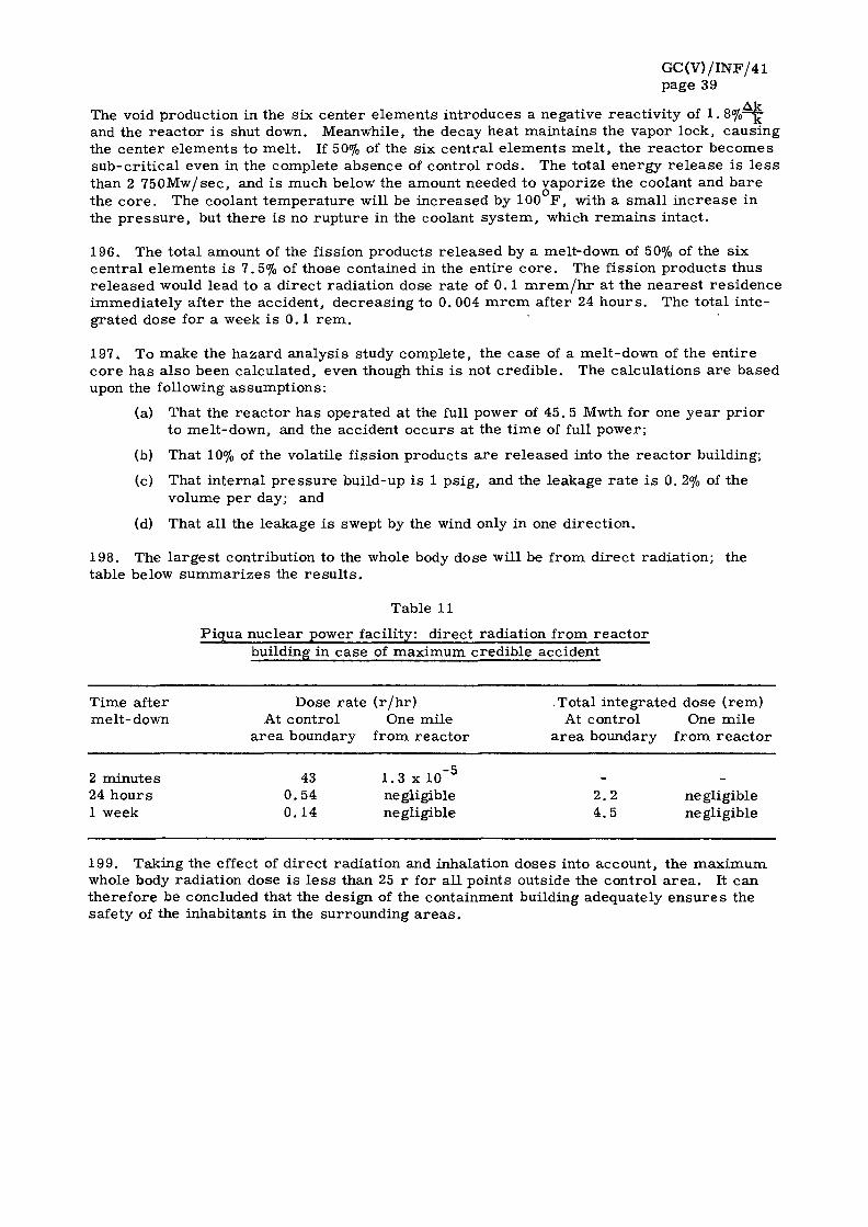
GC(V)/INF/41 page 39
Ak The void production in the six center elements introduces a negative reactivity of 1. 8%—g-and the reactor is shut down. Meanwhile, the decay heat maintains the vapor lock, causing the center elements to melt. If 50% of the six central elements melt, the reactor becomes sub-critical even in the complete absence of control rods. The total energy release is less than 2 750Mw/sec, and is much below the amount needed to vaporize the coolant and bare the core. The coolant temperature will be increased by 100 F , with a small increase in the pressure , but there is no rupture in the coolant system, which remains intact.
196. The total amount of the fission products released by a melt-down of 50% of the six central elements is 7.5% of those contained in the entire core. The fission products thus released would lead to a direct radiation dose rate of 0.1 mrem/h r at the nearest residence immediately after the accident, decreasing to 0.004 mrem after 24 hours. The total integrated dose for a week is 0.1 rem.
197. To make the hazard analysis study complete, the case of a melt-down of the entire core has also been calculated, even though this is not credible. The calculations are based upon the following assumptions:
(a) That the reactor has operated at the full power of 45. 5 Mwth for one year prior to melt-down, and the accident occurs at the time of full power;
(b) That 10% of the volatile fission products are released into the reactor building;
(c) That internal pressure build-up is 1 psig, and the leakage rate is 0. 2% of the volume per day; and
(d) That all the leakage is swept by the wind only in one direction.
198. The largest contribution to the whole body dose will be from direct radiation; the table below summarizes the resul ts .
Table 11
Piqua nuclear power facility: direct radiation from reactor building in case of maximum credible accident
Time after melt- down
2 minutes 24 hours 1 week
Dose rate (r /hr) At control One mile
area boundary from reactor
43 0.54 0.14
1.3 x 10 5
negligible negligible
Total integrated dose (rem) At control One mile
area boundary from reactor
2.2 4.5
negligible negligible
199. Taking the effect of direct radiation and inhalation doses into account, the maximum whole body radiation dose is less than 25 r for all points outside the control area. It can therefore be concluded that the design of the containment building adequately ensures the safety of the inhabitants in the surrounding areas .

GC(V)/ INF/41 page 40
D. Opera t ing pe r sonne l and t ra in ing
200. The staffing plan for the Piqua nuc lea r power facility i s given in Table 12 below.
Table 12
Piqua nuc lea r power facil i ty: staffing plan
Ca tegory Number of p e r s o n s
Admin is t ra t ion
P lan t super intendent 1 S e c r e t a r y 1
Opera t ions
Opera t ions engineer Shift s u p e r v i s o r s Chief o p e r a t o r s P l an t o p e r a t o r s E x t r a ope ra to r Heal th phys ic i s t Heal th phys ics technic ian
Maintenance
Maintenance engineer (mechanical) Ins t rumenta t ion engineer Mechanic / e l e c t r i c i a n E l e c t r o n i c ins t rumenta t ion technician Ins t rumenta t ion r e p a i r m a n Labo ra to ry technician Utili ty man
TOTAL 25
It will be seen f rom the above that t h e r e i s a staff of 25 p e r s o n s for the power r e a c t o r plant only. The t u rbogene ra to r , however , i s being manned by the staff which looks af ter the exis t ing conventional power plants at the s i t e .
201 . A dis t inguishing fea ture i s the fact that the staff has been drawn from among those who have a l ready had long exper ience in th i s field of work , a s can be seen f rom the following informat ion:
Average r e a c t o r and nuc lea r plant exper ience * 6.8 y r s / m a n Average r e a c t o r exper ience only . 5 .7 y r s / m a n Maximum r e a c t o r exper ience only * 7 y r s / m a n Minimum r e a c t o r exper ience only * 3 .5 y r s / m a n
202. The extensive p r i o r exper ience of the o p e r a t o r s , mos t of which was gained at OMRE, s implif ied the p rob lem of t r a in ing .
203. The plant super intendent h a s spent eight y e a r s at Hanford and was at the Canoga P a r k office of USAEC a s the project officer for OMRE and the P iqua faci l i ty. The ope ra t ions eng ineer h a s had four y e a r s exper ience with OMRE and two y e a r s at Savannah R i v e r . The shift s u p e r v i s o r s a r e al l exper ienced having worked at the Hanford, the m a t e r i a l t e s t r e a c t o r and the Westinghouse ins t a l l a t ions . T h r ee of the four chief o p e r a t o r s a l r e a d y hold l i c e n s e s .
1 4 4 4 1 1 1

GC(V) /INF/41 page 41
204. In addition to their original experience the operators have received three months training at Canoga Park in reactor physics, health physics, and electronics theory and application as well as in the study of the specific details of the PNPF system. The actual operation of the model 77 laboratory was included in their program. Later they received training at OMRE in actual operation of an organic system. Since their arr ival at the site, about a year ago, a comprehensive and continuous training program has been in effect, based upon information contained in the safeguards report, standard operating procedures, interconnecting system drawings and design data of the plant. This training has been augmented by frequent lectures at the site.
205. The entire reactor staff will be a part of the pre-operational testing and start-up program and initial full power operation. The testing is being organized with a view to training the staff.
206. The health physicist is fully experienced and has worked at the material test reactor for five years . The health physics technician has not been engaged so far but it is hoped that a well trained person might be available.
207. The maintenance and instrumentation engineers had five years experience in their respective fields of work before joining PNPF. The electronics instrumentation technician had worked in conventional stations but not in a nuclear installation. He spent one month at OMRE and went to a training school run by the manufacturer of the instruments.
208. The laboratory technician has had three years experience in general chemical laboratory work.
E . Construction experience
209. The construction of PNPF started in July 1959 and accordingto the latest schedule the reactor should be critical by November 1961 with full power operation in February 1962. Details concerning the time schedule for the project are given in Table 13.
Table 13
Piqua nuclear power facility: time schedule for the project
Item Revised schedule Actual
Start of construction Start operator training Containment shell erection Complete operator training Steam generator installation Install reactor vessel Pumps and process equipment Completion of construction Pre-operational tests Initial criticality Full power operation
July 1959 May 1959 May 1960 December 1960 August 1961 April 1961 July 1961 September 1961 September 1961 November 1961 February 1962
July 1959 May 1959 June 1960 December 1960 August 1961 July 1961 August 1961
210. The progress of work on this reactor has been largely according to schedule and no major problem arose during construction. By July 1961 the plant was about 85% complete and roughly three months behind the earl ier schedule. The delay was caused mainly by the steel strike which retarded the fabrication and delivery of the pressure vessel by two months.
GC(V)/INF/41 page 42
211. The skills required for building the plant are mainly conventional because of the extensive use of carbon steel in the system. Most of the techniques are those required in the construction of a refinery, excluding the techniques required for building the r e actor core. In the case of the reactor plant the welding calls for greater skill and is subjected to a rigorous X-ray examination before acceptance. The piping and layout of the process system needs careful fabrication and installation under expert guidance. It i s , however, conceivable that skilled workmen having experience in building a refinery or process plant could, under proper supervision, do most of the construction and installation in an organic reactor of this type.
212. In the case of PNPF certain local factors influenced the construction schedule. Originally the reactor was to be located adjacent to the existing steam plant but later it was decided to build it on the other side of the Miami River. This change in location necessitated an extension of the utilities and the erection of additional piping and structure, which added to the total cost of the plant. The site on which the plant has been built was an old city dump and was therefore not the best for the laying of the foundations. Several piles had to be sunk - a process both time-consuming and expensive.
F . Fuel cycle
213. Objectives. The Piqua reactor is to be fueled with 85 aluminum clad slightly enriched uranium metal fuel elements containing 3.5% Mo, and 0.1% Al as a stabilizing material .
214. Development work has been directed toward uranium metal alloyed with from 1.5 to 10% Mo. Additions of ternary alloying materials have also been studied. Prototype fuel elements containing 3.5% Mo and additions of 0.1% Al and 0.5% Si have been irradiated. One element of the plate type has been successfully irradiated for nine months in OMRE (maximum burn-up of 4 000 Mwd/MTU) while a tubular fuel section, approximately the shape of Piqua fuel elements has been irradiated for 17 months. Preliminary evaluations of the tubular element indicates the absences of fouling or dimensional change. Further test specimens of U-10% Mo have shown good stability to 24 000 Mwd/t below 1 050 F and 8 400 Mwd/t at 1 300°F. The warranty for average burn-up is 3 000 Mwd/t.
215. Fuel element design. The fuel elements consist of metallic uranium-3.5% Mo con-taining 1.94% U^35 and 0.1% Al. The fuel is clad with 35 mil aluminum which has a finned surface to increase the area of heat transfer. The cladding is metallurgically bonded to the uranium fuel using a bar r ie r of nickel about 1 mil thick.
216. The fuel elements are circular in cross section, 5. 22 in. outer diameter and 3. 08 in. inside diameter for the main portion, and approximately 80.5 in. in length. The uranium in the element is in the form of two concentric tubes each 0. 21 in. thick, and 3. 6 and 4. 6 in. in mean diameter, respectively. Four sections make up the 34 in. of active fuel length. The fins of the cladding are twisted in a slight spiral along the longitudinal axis. The two concentric fuel tubes are positioned between two 30 mil stainless steel tubes.
217. The ends of the steel tubes are joined to upper and lower and grid plate adapters, and stainless steel wire screens are welded in place at the entrance to the annulus between the tubes and at the bottom cavity in the inner tube. The upper end piece, 5. 6 in. inside diameter, fits in the upper grid plate and is designed to facilitate fuel handling and supports the weight of the element. The lower end piece, 4.36 in. inside diameter, guides the element in the lower grid plate. Adjustable flow-regulating orifices are installed at the upper grid plate adapter of all fuel elements except the 13 elements which accommodate the control rods to regulate the flow through the outer regions where the heat generation is less . The orifices will be adjusted during shut-down to equalize the temperature r i se .
218. As of May 1961, 46 fuel elements were completed, passed inspection, and were accepted.

GC(V)/INF/41 page 43
219. Fuel management. The initial order was for 100 elements, and recently an additional 20 elements were ordered. The core consists of 85 fuel elements. Future requirements of fuel during the five years in which the Government will operate the plant will depend upon developments, and possibly sintered aluminum fuel may be used.
220. The reactor will operate upon a partial fuel loading cycle. It will be shut down periodically (at four to six months intervals) and the spent fuel will be replaced through the top cover and shield of the vessel by means of a fuel handling cask placed over the port. After replacing a part of the core, a sample of the remaining fuel elements will be inspected.
221. The spent fuel elements are placed in a storage pool which can hold 100 elements. After cooling the spent fuel will be shipped for re-processing in a 30 ton dual purpose cask (specially designed for Elk River and Piqua fuel) which will accommodate 13 Piqua elements.
G. Cost data
222. The Piqua reactor is being designed and constructed for USAEC by Atomics International under a fixed price contract. The current cost estimate is $9 .1 million which includes $1.2 million for the fabrication and development cost of 100 fuel elements. The cost of pre-construction research and development, and operation and testing (excluding reactor designers trainingcosts) are estimated respectively at $3.5 and $ 1 . 2 million giving a total project cost to the Government of $13.8 million for the reactor plant, research and development, fuel and operation and training.
223. Construction. As of May 1961 the total cost incurred or committed for design (94% complete) and construction (84% complete) was $7. 76 million ($1 . 6 million for engineering and $6.3 for construction), compared to the authorization of $7. 93 million.
224. Fuel. The cost of the initial order for fabricating 100 fuel elements is estimated at $1.2 million which will include withdrawal charges for source and special nuclear mater ia ls , escalation charges, and contingencies. This gives a unit cost of about $147/kg U. However, as mentioned in paragraph 219 above, an additional 20 fuel elements were recently procured the cost being $102 000 ($5 100/element) or $63/kg U which is less than one-half the unit cost of the initial order. At the warranty burn-up level of 3 Mwd/kg U and 25% thermal efficiency this fabrication cost contributes 3.5 mills/kwh to the fuel cost. The total fuel cost for a second Piqua reactor has been estimated to be of the order of 5 mills/kwh for an exposure of 3 Mwd/kg U. The fuel cost would be d ras tically reduced if high burn-ups are achieved as has been indicated by irradiation of test specimens of U-10% Mo.
225. Operation and maintenance and organic make-up costs. Estimates of 2 to 5 mills/kwh have been made for operation and maintenance including the cost of organic make-up. Data concerning the estimated operation and maintenance costs based upon a preliminary analysis by the City of Piqua are given in Table 14 below.

GC(V)/ INF/41 page 44
Table 14
P lqua nuc lea r power facili ty: operat ion and maintenance cost e s t i m a t e s
I tem $ / y r $ / k w - y r Mi l l s /kwh (at 80% load factor)
Gene ra l supp l i e s , m a t e r i a l s 17 000 1.5 0 . 2 and s e r v i c e s (excluding e l ec t r i c i t y and organic make-up)
Maintenance 49 000 4 . 3 0 . 6 Too l s , t e s t equipment , s p a r e p a r t s , e t c .
Heal th phys ics and safety 50 000 4 . 4 0 .6 Env i ronmenta l su rvey , c lothing, badge renewal and safety equipment
Analyt ical l abora to ry 9 000 0 .8 0 .1
S a l a r i e s 276 000 24 3 .4
TOTAL 401 000 35 5
226. The es t ima ted r e q u i r e m e n t s for organic make -up vary f rom 30 to 60 l b s . / h r . At 1 5 / l b . th i s would be equivalent to about 0 .4 to 0. 8 mi l l s / kwh for organic m a k e - u p .
227. Cur ren t ly the environmenta l survey and cont ro l i s being conducted by an outside conce rn for $10 000 p e r y e a r .
H. In tegra t ion of the r e a c t o r into the util i ty s y s t e m
228. The P iqua r e a c t o r i s expected init ial ly to opera te on base load, and would be uti l ized a s a load following plant only after a demons t ra ted per iod of unin ter rupted and a s s u r e d opera t ion . Under the cont rac t with the r e a c t o r manufac tu re r t h e r e i s a 28 day w a r r a n t y and a 60 day t ra in ing per iod before the r e a c t o r i s tu rned over to the util i ty for opera t ion .
229. The power sys t em of the City of P iqua i s an isola ted s y s t e m cons is t ing of a s ingle power s ta t ion supplying e lec t r ic i ty for local u s e , and s t e am to about ten indus t r i a l u s e r s .
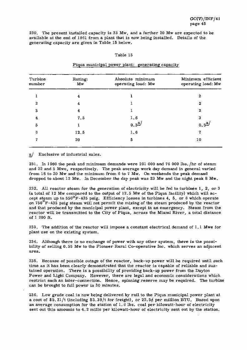
GC(V)/ INF/41 page 45
230. The p r e s e n t ins ta l led capaci ty i s 33 Mw, and a fur ther 20 Mw a r e expected to be available at the end of 1961 f rom a plant that i s now being ins ta l l ed . Deta i l s of the genera t ing capaci ty a r e given in Table 15 below.
Table 15
P iqua municipal power plant: genera t ing capaci ty
Turbine Rat ing: Absolute min imum Minimum efficient number Mw opera t ing load: Mw opera t ing load: Mw
1
2
3
4
5
6
7
4
4
4
7 .5
1
12 .5
20
1
1
1
1.6
0 . 3 * /
1.6
5
2
2
2
3
0.5-
7
10
aj Exc lus ive of indus t r i a l s a l e s .
231 . In 1960 the peak and min imum demands w e r e 291 000 and 76 000 l b s . / h r of s t e a m and 22 and 5 Mwe, r e spec t ive ly . The peak ave rage work day demand in genera l va r i ed from 18 to 20 Mw and the min imum f rom 6 to 7 Mw. On weekends the peak demand dropped to about 12 Mw. In December the day peak was 23 Mw and the night peak 8 Mw.
232. All r e a c t o r s t e am for the genera t ion of e l ec t r i c i t y will be fed to t u rb ines 1, 2, o r 3 (a to ta l of 12 Mw compared to the output of 12.5 Mw of the P iqua facility) which will a c cept s t e a m up to 550°F-435 ps ig . Efficiency l o s s e s in t u rb ines 4 , 5 , or 6 which ope ra te on 750 F-435 ps ig s t e a m will not p e r m i t the mixing of the s t e a m produced by the r e a c t o r and that produced by the municipal power plant , except in an e m e r g e n c y . S team f rom the r e a c t o r will be t r a n s m i t t e d to the City of P iqua , a c r o s s the Miami R i v e r , a to ta l d i s tance of 1 200 ft.
233. The addition of the r e a c t o r will impose a constant e l e c t r i c a l demand of 1.1 Mwe for plant use on the exis t ing s y s t e m .
234. Although t h e r e i s no exchange of power with any o ther s y s t e m , t h e r e i s the p o s s i bil i ty of se l l ing 0. 55 Mw to the P i o n e e r Rura l Co-opera t ive Inc . which s e r v e s an adjacent a r e a .
235. Because of poss ib le outage of the r e a c t o r , back-up power wil l be r e q u i r e d unt i l such t ime a s it h a s been c l ea r ly demons t ra ted that the r e a c t o r i s capable of r e l i ab l e and s u s tained opera t ion . The re i s a poss ib i l i ty of providing back-up power f rom the Dayton P o w e r and Light Company. However , t h e r e a r e legal and economic cons ide ra t ions which r e s t r i c t such an in te r -connec t ion . Hence , spinning r e s e r v e may be r e q u i r e d . The tu rb ine can be brought to full power in 30 m i n u t e s .
236. Low grade coal i s now being de l ivered by r a i l to the P iqua munic ipa l power plant at a cos t of $ 5 . 21 / t (including $ 3 . 3 9 / t for f re ight) , o r 22.5j£ p e r mi l l ion BTU. Based upon an ave rage consumption for the s tat ion of 1. 6 l b s . coal p e r k i lowat t -hour of e l ec t r i c i t y sent out t h i s amounts to 4 . 2 m i l l s p e r k i lowat t -hour of e l ec t r i c i ty sent out by the s ta t ion .

GC(V)/INF/41 page 46
I. Selected references
237. A list of selected references concerning the Piqua nuclear power facility is given below:
"Preliminary Design Description for the Piqua Organic Moderated Reactor Plant, Piqua Ohio", NAA-SR-3300, Atomics International, Canoga Park, Calif. (18 August 1959)
STIENS, R. R. , "Dust Collection System for Piqua Residue Handling Prototype", NAA-SR-MEMO-3927, Atomics International, Canoga Park, Calif. (28 May 1959)
"Small-sized Organic Moderated Reactors (10-40MWE)", report TID-8511, USAEC, Washington, D.C. (October 1959)
WEISNER, E . F . , "Engineering Design of Piqua OMR", Nuclear Engineering, v. 5, No. 45, London (February 1960) p. 68-71
BAUMEISTER, E . B . and WILDE, J . D . , "Selection of the Piqua OMR Fuel Element", NAA-SR-4239, Atomics International, Canoga Park, Calif. (15 March 1960)
NADLER, H . , "Piqua Prototype Handling System", NAA-SR-4361, Atomics International, Canoga Park, Calif. (1 May 1960)
HOWELL, J . D . et a l . , "OMR (Piqua) Unitized Control-Safety Rod Prototype Tes ts" , NAA-SR-5077, Atomics International, Canoga Park, Calif. (30 June 1960)
GILROY, H. M. and WILSON, J . H . , "Piqua OMR Waste Gas Disposal", NAA-SR-4576, Atomics International, Canoga Park, Calif. (15 July 1960)
STIENS, R .R . , "Piqua OMR High Boiler Handling", NAA-SR-4791, Atomics International, Canoga Park, Calif. (30 August 1960)
CORPORALES, G.W. and BENSON, P . R . , "Operation of the Piqua OMR Degasification System Prototype", NAA-SR-4894, Atomics International, Canoga Park , Calif. (30 August 1960)
WEISNER, E . F . , JACOBSON, J . and WHEELOCK, C. W., "Design of Small Central-Station Organic-Reactor Power Plants" , Small and Medium Power Reactors, v. 1, IAEA, Vienna (1961), p . 339
BLEY, W.N. and BURKHARDT, R. W. "Piqua OMR Purification System Development", NAA-SR-5073, Atomics International, Canoga Park , Calif. (1 November 1960)
BINSTOCK, M.H. , "Fuel Element Development for Piqua OMR", NAA-SR-5119, Atomics International, Canoga Park, Calif. (30 June 1960)
"Final Safeguards Summary Report for the Piqua Nuclear Power Facility", NAA-SR-5608, Atomics International, Canoga Park, Calif. (February 1961)
BENAROYA, V., and MINER, S. , "Process Systems for the Piqua Organic Moderated Reactor", American Institute of Chemical Engineers meeting. New Orleans, La. (26 February - 1 March 1961)

GC(V) /INF/41 page 47
V. THE BONUS POWER REACTOR
A. General
238. The BONUS is a boiling-water reactor with integral superheat and a net electric output of 16. 3 Mwe. It is now under construction in Puerto Rico as part of USAEC's program of demonstrating the technical and economic feasibility of nuclear superheat. It is located at Punta Higuera, on the westerly tip of Puerto Rico, close to the sea shore. It will form part of the system of the Puerto Rico Water Resources Authority (PRWRA). Under arrangements between PRWRA and USAEC, PRWRA will supply the site, the turbogenerator facilities and perform the design and engineering of the conventional part of the plant. USAEC will furnish the complete reactor and auxiliaries. The prime contractor for the reactor plant is the General Nuclear Engineering Corporation, which will perform the necessary development work, design and star t up the reactor and carry out post construction research. The construction contractor is Maxon Construction Company and the reactor components are being procured from various suppliers at a fixed price.
239. The construction of the plant started in the last quarter of 1960 and it is estimated that the entire project will be completed within 30 months, which is a relatively short time for the construction of a nuclear plant involving several new features.
B. Important design features
240. A summary of important data concerning the BONUS power reactor is set out in Annex III, and a schematic diagram of the reactor system is shown in Figure 3.
241. Objectives. The primary objective of this plant is to demonstrate the use of integral superheat. In this reactor the integral nuclear superheater is located on the periphery and the boiler in the center of the core. It is the first reactor of this particular design and is expected to yield extremely interesting data on the technical and operational aspects of a nuclear superheat reactor , which will provide a basis for extrapolation of certain design features to larger plants. In designing the reactor great importance has been given to safety, as has been explained in paragraphs 259 - 263 below. It is not meant to be a load following plant but a base load unit. In the initial phases, it will feed into the network whatever power it can produce with priority being given to the development of essential research information.
242. The lower power level of 16. 3 Mwe was chosen so that the required information on feasibility and operational problems could be obtained at minimum cost. The plant is convertible to a straight boiling reactor in conjunction with a conventional superheater should the performance of the nuclear superheater prove to be less than satisfactory.
243. Core. The reactor is designed to deliver 152 000 lbs /hr of steam at 850 psig and 900°F, producing 50 Mwth and 16. 3 Mwe net with a plant efficiency of 32%. Of 50 Mwth heat output, 38. 6 Mwth are generated in the central boiler region and 11.4 Mwth in the superheating region.
244. The boiler region is 35. 5 in. square and the entire core measures 54 in. across the flats, and the active length is about 55 in. The total area of the core is equivalent to a circle having a diameter of about 56 in. The power density in the central region is 32. 9 kw/l, and in the superheating region 11. 6 kw/l. Water is circulated through the 64 fuel elements in the boiler section by forced circulation, and the flow to each assembly is regulated by orifices in the inlet plenum. The rate of flow is 7 500 gpm and two pumps are used for reliability and safety instead of only one. The water enters the core at 532°F, producing steam at 540°F, which is separated from the water by gravitation. Before entering the superheater, this 5% moist steam passes through conventional corrugated plate dr iers which reduce the moisture to below 0.1%. The dry steam at 540°F makes four passes through superheater elements arranged in groups of eight each, and is superheated to 900°F.

GC(V)/INF/41 page 48
245. Exhaust steam from 32 superheater assemblies is collected in 11 separate pipes leading to the outside of the reactor shield and monitoring is carried out for temperature flow and radioactivity.
246. Stability. No practical experience has yet been gained in the dynamics of an integral superheater reactor, although Borax-5 will, in the near future, yield useful data on the subject. The theoretical analysis of the stability of BONUS was undertaken by using a mathematical model similar to EBWR, but modified to include the integral superheater. Important parameters and variables were considered in obtaining a set of transfer functions which were simulated on an analog computer and the frequency response of the open and closed loop system was studied. The results indicate that the BONUS system will be very-stable even under adverse conditions not likely to be encountered in actual operation. The linear transience response also indicates a marked degree of stability.
247. Pressure vessel. The pressure vessel is made of 2. 75 in. thick carbon steel clad internally with 0. 25 in. of stainless steel. Its internal diameter is 7 ft. , height 27. 5 ft., and weight 57 tons. It is designed to withstand 1 150psig at 600°F, but will operate at 950 psig and 540°F.
248. Thermal and biological shield. Outside the reactor pressure vessel a steel tank serves as a support for the vessel and as a container for the iron-water thermal shield. In the radial direction, this external thermal shield is followed by a 9 ft. thick biological shield made of ordinary concrete. Special plugs or tanks of lead, concrete and water are used for shielding above and below the pressure vessel. The top shield plug is removable for access to the control rod drive mechanism and to the bolts on the top-head itself.
249. The shield design is based upon the consideration that no person in the controlled area will receive a radiation dose of more than 5 r e m / y r under normal conditions, and outside the controlled area of more than 0, 5 rem/yr . The components containing radioactive coolant water or steam are located in controlled areas and have limited access during reactor operations. Shortly after reactor shut-down when nitrogen-16 with a half life of 7. 35 sees decays, access to the area for routine maintenance is possible.
250. In high activity areas the typical dose rates at various locations due to nitrogen-16 are in rem/hr : pump room 10, condenser hotwell 10, feedwater heater 1, air ejector 90. All these areas are inaccessible during operation. At the main superheated steam outlet pipe, the dose rate is at one meter, without concrete shield, 0. 09 r em/hr . In the other areas outside the reactor and component shields, the radiation dose is 2. 5 mrem/hr or less to allow a normal 40 hours work week.
251. Containment shell. The containment shell for the BONUS reactor represents a new approach and is different from the usual two building arrangements used in current plants where the reactor is located in a steel dome designed for high pressures and the turbogenerator and control room in a separate conventional building. The design of the BONUS containment shell is based on the consideration that in order to contain a certain amount of vapor and fission products it is just as well or perhaps better to employ a large volume low pressure shell instead of a small volume high pressure one. It can be shown that the amount of steel needed is the same in either case as long as the amount of vapor to be contained is the same.
252. Consequently, the BONUS reactor has only a large shell 167 ft. in diameter and made of 3/8 in. thick steel, which houses the reactor, the turbogenerator, the condenser, the auxiliaries and the storage pit. It is designed for a low pressure of 5 psig as compared to 16 psig for EBWR, 29. 5 psig for the Dresden plant, 75 psig for VBWR and 52. 8 psig for the Shippingport reactor.
253. According to the reactor designer some of the disadvantages of the two building arrangement with a small high pressure containment shell for the reactor are:
GC(V)/INF/41 page 49
(a) The erection of the equipment is difficult because of the relative lack of space in the shell;
(b) The time required for construction is longer because the shell has to be put up first before internal concrete work can be started and the equipment can be erected;
(c) Numerous penetrations in the high pressure shell for pipes and cables necessitate special non-leakage seals involving extra cost and maintenance;
(d) Some of the equipment in the reactor shell and the turbogenerator building has to be duplicated. For instance, one separate crane is needed in each buildingj which adds to the plant costs;
(e) Longer steam and feed water lines are needed from the reactor to the turbogenerator building, and they have to be provided with duplicate valves and auxiliary controls;
(f) During air leak tes ts , the high pressure shell requires special provision for protecting the equipment;
(g) The provision of emergency shut-down cooling becomes difficult. If the water storage tank is outside, it has to be able to withstand the same high pressure as the shell to be able to inject water under gravity into the core;
(h) For shells above 15 psig, ASME codes apply which require X-raying of all joints in addition to leak tes ts . This imposes a high economic penalty; and
(i) In the event of an accident leading to pressurization, the probability of harm to the personnel is greater in a high pressure building than in a low pressure one.
254. The disadvantage of the large low pressure shell is that it requires more steel sur face area, and a greater amount of work in excavation, foundation, welding, radiographing, insulation, etc. But if the extra space is used for housing the turbogenerator, the condenser and other essential equipment, as has been done in the case of BONUS, then the additional expenditure may be justified.
255. The building is designed for 5 psig and 150°F, and a leakage rate of 0. 25% of volume/day. The temperature and pressure expected in case of maximum credible accident are however less than this rating. Because of the elimination of a large number of penetrations, the less onerous code requirements for low pressure buildings, the use of a single handling crane and the shortening of water and steam lines and cables, it is expected that an over-all lowering in construction costs will be effected. Moreover, the low p res sure shell provides greater insurance than the high pressure one against the leakage of objectionable amounts of radioactivity into the atmosphere, and greater safety for the population in the surrounding area.
256. Fuel handling. The fuel handling system is s imilar to that used for EBWR. A properly mounted shield cask of lead is used which is capable of being moved on rai ls between the reactor and the adjacent storage pool for spent fuel. The reactor is shut down and the shield plug is removed together with the vessel core and rod drives. After centering the index plug of the shield over the irradiated fuel element in the core or superheater, it is lifted by a grappling device into the cask and there discharged in the storage pool filled with water, where it is allowed to cool off. For shipment to a processing plant, the fuel elements are loaded into special casks while submerged under water.
257. Waste disposal system. The radiolytic and radioactive gas disposal system disposes of non-condensable gases removed from the main condenser by the steam jet ejector. Normally, these gases are nitrogen-16 and argon-41, and can be released through the stack after an interval of two minutes. To deal with fuel or element failures and consequent r e lease of fission products, a vapor sphere of 1 300 ft.^ is provided to permit complete collection of all exhaust for 30 minutes, during which the reactor can be properly shut down.

GC(V)/INF/41 page 50
The disposal of the upper gases is done either by dilution and release with the atmosphere, or by passing it through a charcoal bed which retains active gases.
258. To hold liquid wastes, two 3 000 gallon retention tanks and one 1 000 gallon ion-exchange neutralizer are provided. Since very little activity is expected in this water, only minimum waste-processing facilities are planned initially for BONUS. Arrangements are being made for concentrating the water so that it can be stored in drums as solid waste, for eventual disposal through burial in a pit.
C. Safety
259. Safety in design. As stated ear l ier , the primary emphasis in the design of BONUS is on safety. To all the inherent safety features of a boiling water reactor have been added the advantages of a UO2 fuel and several automatic built-in safety devices have been incorporated to prevent or terminate any potential hazard. The use of an integral superheater introduces, however, new problems of safety, such as:
(a) The change in reactivity owing to the expulsion from, or addition of, water to the steam coolant gaps of the superheater fuel elements; and
(b) The cooling of superheater fuel elements in case of loss of steam flow and the prevention of excessively high cladding temperatures.
260. The superheater fuel region is so designed that there is very little change in r e activity because of expulsion or addition of water at operating temperatures. For instance, if all the water is expelled from the superheater when operating at 525°F and low power, the net change in reactivity is almost zero. At full power, sudden flooding of this region would add only 0. 2%=fc m reactivity. During start-up, the rapid expulsion of the cold (60°F) moderator from the superheater could cause a 0. 9%^£ change in reactivity. To safeguard against this, an interlock system has been provided to prevent nuclear start-up unless the temperature of the water moderator is 500°F. An electrical preheater is provided to heat the water to 525°F before start-up.
261. To meet the hazards from the loss of steam coolant in the superheater region, the cooling system has been so designed that there is always sufficient cooling through the superheater assemblies to prevent excessive temperatures. If the steam flow is stopped two minutes after a scram, no damage is done to the fuel elements. Should this arrangement also fail, then the fuel assemblies are designed to be able to dissipate their heat by radiation without any melting of the cladding.
262. Normally, the steam from 11 superheater pipes from various segments of the core is continuously monitored and if the temperature in any one exceeds 950°F or there are other indications of a restriction of steam flow in the superheater, an immediate scram takes place and adequate cooling for air fuel is provided in a shut-down condition.
263. Besides the special safety features for the superheater, many other safeguards similar to those for other boiling-water reactors have been provided. Some of these are summarized below:
(a) The boiling zone of this reactor will automatically limit the power level of the reactor. Owing to the negative reactivity effect, additional steam voids are formed as the power level increases;
(b) To shut down the reactor, two independent systems are provided. The primary system has 17 control safety rods which fall within two seconds at any indication of trouble. The back-up system to be initiated by the operator can shut down the reactor by slow injection of boron solution;
(c) An emergency shut-down cooling system has been incorporated, which is independent of all power sources and conies into action when the normal cooling system fails;

GC(V)/ INF/41 page 51
(d) All safety devices and cont ro ls a r e designed to p reven t malfunction o r to cause a s c r a m in case of a malfunction;
(e) An e m e r g e n c y w a t e r sp ray s y s t e m provides sufficient cooling to p reven t mel t ing of the fuel e l emen t s and consequent r e l e a s e of f ission p r o d u c t s , even in c a s e of comple te dra inage of coolant f rom the r e a c t o r v e s s e l ;
(f) A building s p r a y s y s t e m has been incorpora ted to r educe p r e s s u r e and t e m p e r a t u r e r e su l t i ng f rom the r e l e a s e of all r e a c t o r wate r ; and
(g) Because of the locat ion of the r e a c t o r in a h u r r i c a n e a r e a , the containment she l l i s designed to withstand winds up to 155 mph.
264. Control . The BONUS r e a c t o r i s control led by 17 two p e r cent boron s t a i n l e s s s t e e l r o d s . The nine cont ro l r o d s located in the boiling region a r e 1/8 in. thick c r u c i f o r m s with a 7 in. span. The rods located between the boil ing and superhea t ing reg ions ( there a r e no control r ods in the s u p e r h e a t e r as such) a r e £ in. thick s l a b s , 12 in. wide. D r i v e s for the rods a r e of the rock and pinion type and a r e mounted above the e l l ip t ica l c o v e r of the p r e s s u r e v e s s e l .
265. With e n r i c h m e n t s of 1. 85% in the boi le r and 3. 5% in the s u p e r h e a t e r r eg ion , the ini t ia l e x c e s s reac t iv i ty unde r cold c lean condit ions i s 16. 6 % = . . At ful l -power opera t ion and with equ i l ib r ium xenon and s a m a r i u m , the ini t ia l e x c e s s reac t iv i ty i s 6.7%—r-. The 17 cont ro l rods have a combined s t r eng th of 19%=j | when the r e a c t o r i s cold. This p r o vides a shut-down m a r g i n of 2. 4 % ^ k unde r cold c lean condit ions.
k Ak
266. The ini t ia l e x c e s s r eac t iv i ty of 6. 7%"~T i s cons idered sufficient to achieve a b u r n - u p of 6 500 Mwd/t . By r ep lac ing four c e n t r a l a s s e m b l i e s of n a t u r a l u ran ium by enr iched ones , enough addit ional r eac t iv i ty will be gained to r e a c h 10 000 Mwd/t . T h e r e wil l be an inward shifting of the ou te r fuel e l emen t s which will a l so help in flux flattening.
267. Site. Based upon v isua l inspec t ions , co re d r i l l i ngs , topographica l m a p s , m e t e o r o logical and se i smolog ica l .data, the d is t r ibut ion of population, the avai labi l i ty of cooling wa te r , e t c . , the s i te was found to m e e t a l l the e s sen t i a l r e q u i r e m e n t s for the safe locat ion of a nuc l ea r power plant . The fact that the wind a lmos t a lways blows towards the s e a m a k e s this s i te m o r e sui table f rom the standpoint of minimiz ing potent ial radioact iv i ty h a z a r d . The plant i s designed to withstand h u r r i c a n e s with speeds up to 150 mph, a s well a s ea r thquakes .
268. The average e levat ion of the s i te i s 175 ft. above s e a - l e v e l and the su r face and unde r ground run-off i s t owards the s ea .
269. The n e a r e s t communi ty , about 2 m i l e s d is tant , has a population of 1 065, and the n e a r e s t c i ty , 13 m i l e s away, of 59 000. The d is t r ibut ion of population at v a r i o u s d i s t ances is shown in Table 16 below.
Table 16
Populat ion dis t r ibut ion
Dis tance in m i l e s Populat ion d e n s i t y / s q . mi le
0 .25 (exclusion a r ea ) 40 0 .50 470 0.75 830 1.00 1 160

GC(V)/ INF/41 page 52
270. Analys is of max imum cred ib le accident . The wors t r e a c t o r accident which can logical ly be postulated for the BONUS r e a c t o r i s the sudden and complete rup tu re of the 16 in. inlet pipe at the bot tom of the p r e s s u r e v e s s e l . This d r a in s out a l l the wa te r in the r e a c t o r v e s s e l in four seconds . A detai led ana lys i s of th i s accident and consequences thereof i s given in the p r e l i m i n a r y h a z a r d s s u m m a r y r e p o r t and is based upon ve ry p e s s i mi s t i c a s sumpt ions , including the following:
(a) That p r i o r to the accident the r e a c t o r has opera ted at full power for a y e a r with consequent accumulat ion of f ission products in the fuel; and
(b) That a l l the fuel e l emen t s me l t , r e l e a s i n g 100% of the vola t i le , and 30% of the non-vola t i le f ission p roduc t s .
271. Immedia te ly after the hypothet ical r u p t u r e , s t e a m i s r e l e a s e d into the dome; the building spray ing s y s t e m , which does not depend upon any power s o u r c e , comes into opera t ion . The cooling effect of the spray ing wa te r r educes the p r e s s u r e by a factor of two in the f i r s t half hour . This wa te r a l so d i s so lves 99% of iodine in the f ission product cloud. The leakage r a t e d e c r e a s e s f rom 0. 25% of volume pe r day to 0. 177% of the volume p e r day in the f i r s t half hour , and r e m a i n s unchanged the rea f t e r .
272. Assuming that ex t r eme ly a d v e r s e me teoro log ica l conditions exis t at the t ime of the r e l e a s e of f ission produc ts f rom the dome, the calculated dose r a t e s at va r ious d i s tances f rom the she l l will be a s shown in Table 17 below.
Table 17
BONUS power r e a c t o r : e igh t -hour in tegra ted dose (rep)
( F o r average lapse condition)^/
Dis tance in Thyroid Be ta Gamma Population Average population m e t e r s subjected to
rad ia t ion haza rd
2 12 20 25
aj Th i s i s cons idered to be the wors t expected condition.
273. F o r the purpose of r e f e r e n c e , the max imum p e r m i s s i b l e exposure leve ls which have genera l ly been accepted by a n u m b e r of med ica l exper t s [ 6 ] a r e 25 r e m for whole body, bone , lung, e t c . , and 1 500 r e m for the thyroid .
274. Compar ing these p e r m i s s i b l e leve ls with the rad ia t ion doses shown in the above tab le , it has been concluded in the h a z a r d s evaluation r e p o r t that in the event of the m a x i m u m cred ib le accident , the amount of radioact iv i ty r e l e a s e d will not const i tute an ext r e m e rad ia t ion h a z a r d for the population in the sur rounding a r e a .
300 402.5 805
1 210 1 610
5.12 3.29 1.17 0.64 0.55
0.144 0.085 0.025 0.013 0.008
0.045 0.030 0.011 0,007 0.004
-40 470 830
1 160
[ 6 ] BRITTAN, R . O . , "Reac to r Containment (including a technica l p r o g r e s s r ev iew)" , ANL-5948, Argonne Nat ional Labo ra to ry , L e r m o n t , 111. (May 1959).

D. Opera t ing pe r sonne l and t ra in ing
275. The p rov is iona l staffing plan i s s e t out in Table 18 below.
Table 18
BONUS power r e a c t o r : staffing plan
Category Number of p e r s o n s
Adminis t ra t ion
Plant super in tendent 1 Ass i s tan t plant super in tendent 1 C l e r k s 2
Opera t ion
Shift s u p e r v i s o r s Cont ro l r o o m o p e r a t o r s Auxi l iary o p e r a t o r s Relief o p e r a t o r Heal th phys ic i s t Chemis t o r technic ian J a n i t o r s
TOTAL
5 10
5 1 1 1 2
9
38
276. At the p r e s e n t t i m e , five p e r s o n s a r e attending the ORSORT c o u r s e for r e a c t o r opera t ions and superv i s ion , which will l a s t for one y e a r . The shift s u p e r v i s o r s will r e ceive an addit ional s ix mon ths ' t r a in ing on a bo i l ing-wate r r e a c t o r .
277. The exis t ing r e s e a r c h r e a c t o r at P u e r t o Rico i s being used for the t r a in ing of o p e r a t o r s who have had p rev ious exper ience of s t e a m plants in the PRWRA s y s t e m .
278. The to ta l budget for the t r a in ing of pe r sonne l i s $300 000.
E . Const ruc t ion exper ience
279. Actual cons t ruc t ion of the plant s t a r t e d in August 1960 and the t a r g e t da te for full power operat ion i s F e b r u a r y 1963. This total per iod of 30 months is r e l a t ive ly sho r t for the cons t ruc t ion of a n u c l e a r plant which inco rpora t e s s e v e r a l new f ea tu re s . The p r o g r e s s up to date indica tes that cons t ruc t ion i s ahead of the proposed schedule s e t out in Table 19 below which, i t i s expected, will be met .
GC(V)/INF/41 page 53

GC(V)/INF/41 page 54
Table 19
BONUS power reactor: time schedule for the project
Item Proposed
Start of construction August 1960 Start of personnel training August 1960 Erection of containment shell June 1961 Pressure vessel installation October 1961 Turbogenerator and steam equipment August 1962 Completion of training September 1962 Construction complete November 1962 Cold testing September 1962 Initial criticality December 1962 Pull power operation February 1963
280. An interesting feature of this plant is that it is being built in an area which is not highly industrialized and experience gained in its construction may have some useful parallels with developing countries. The local contractors in Puerto Rico are actively participating in different phases of construction and providing skilled labor for welding, electrical and piping work. It is hoped that the details of the participation of local industry in this project will be available in the near future.
F. Fuel cycle
281. Objectives. One of the objectives is to verify that superheater fuel elements having thin-walled cladding can operate with high integrity in a high temperature steam environment over a long period and thus achieve acceptable fuel cycle costs. The amount of burn-up which can be achieved and the degree of long-term contamination of the turbine owing to transport of stainless corrosion products, of water impurities, and of fission products from fuel element failure will be determined by actual operation of the station. The cost will increase substantially if it is found necessary to replace the superheater fuel before it reaches its design value.
282. Fuel element design. Of the 64 water cooled boiler fuel assemblies, in an 8 by 8 array, 60 contain zircaloy clad UO2 enriched to 1. 85% U 2 3 5 and the four central ones contain natural UO2 (total loading of 2 546 kgU). The 32 steam cooled superheater fuel as semblies which surround the boiler assemblies contain stainless steel clad UO2 enriched to 3. 5% U 2 3 5 (total loading of 1 627 kgU).
283. Each boiler fuel assembly contains 32 fuel rods, 0.450 in. inside diameter and 0. 500 in. outer diameter, containing UO2 pellets 0. 445 in. in diameter. The fuel rods are segmented, having lengths equal to one-half of the active core length of 54 in. and fastened at their ends to zircaloy grid plates. Two such sub-assemblies are then placed end-to-end in a zircaloy box, 0. 086 in. thick and 3. 929 in. square, to form a complete fuel assembly. The two grids at the center of each assembly and the grids at the end are welded to the zircaloy box. Guide pins in the ends of individual fuel rods, mounted with springs, pass through holes in the top and bottom grid plates but are not fastened to the grids so as to allow individual thermal expansion.
284. The zircaloy fuel assembly is riveted to stainless steel end fittings to permit accurate positioning in the core-support plate at the bottom and the egg-crate superstructure at the top.

GC(V)/INF/41 page 55
285. Each superheater fuel assembly consists of 32 stainless steel rods 0. 506 in. outer diameter and 0. 542 in. inside diameter containing U0 2 pellets, 0. 500 in. in diameter. Each fuel rod is surrounded by a thin stainless steel coolant tube which defines an annular path for the steam flow in cooling the fuel. Surrounding the coolant tube is an 18 mil p res sure tube which isolates the superheater fuel from the water surrounding each element, and provides a static steam insulating gap with respect to the coolant tube. This prevents excessive loss from the superheated steam to the water.
286. Fuel management. Burn-ups of 11 000 Mwd/MTU are expected to be achieved for both the boiler and the superheater fuel elements. The superheater elements will be ro tated 180° to gain reactivity and achieve uniform burn-up. These burn-ups correspond to fuel residence times of 2. 6 and 4. 7 years for the boiler and superheater fuel, respectively.
G. Cost data
287. The only data received are estimates presented in the preliminary design study made in January 1960; they are set out below:
(a) Construction
The construction cost estimates are as follows:
Table 20
BONUS power reactor: construction cost estimates
(In thousands of dollars)
Item
Land and land rights Structures and improvements Reactor plant equipment Turbogenerator unit Accessory electrical equipment Miscellaneous power plant equipment
Sub-total Escalation (7% of the sub-total)
Sub-total Contingency (15% of the sub-total)
Sub-total Indirect construction costs
(15% of the sub-total) Interest during construction
Sub-total Start-up supervision Engineering and design
TOTAL (plant cost) TOTAL (plant cost in
$/net kwe)
Cost
1 611 2 928 1 540
745 70
6 894 483
7 377 1 106
8 483
1 272 (not included)
9 755 50
1 345
11 150
684
It is expected that it will take 35 months to design, build and bring the plant to full power operation.

GC(V) /INF/41 page 56
<b) Fuel
The estimated fuel cost is as follows:
Table 21
BONUS power reactor: estimated fuel cost
(In dollars per kgU)
Item Boiler Superheater
Cost of U 2 3 5 consumed Value of plutonium produced Net burn-up cost Chemical processing cost Chemical processing loss U , 1% Chemical processing loss plutonium, 1% Conversion plutonium to metal Fuel fabrication cost Conversion salt to UFg Interest of fabrication capital, 6% Use charge on new fuel in shipping Use charge on new fuel in storage Use charge on fuel in reactor Use charge on irradiated fuel Shipping new fuel to site
134.90 56.76 78.14 44.00 0.63 0.57 7.02
140.00 5.60 13.02 0.66 1.32 13.56 5.22 2.00
194.40 36.60 157.80 55.00 2. 61 0.37 4.53
125.00 5.60 19.49 1.52 3.04 67.27 27.00 2.00
TOTAL ($/kgU) 311.74 471.23
The loadings for the boiler and superheater fuel are 25 646 and 1 627 kilograms respectively, hence the effective average fuel cost is $352/kgU. Based upon the generation of 8. 6 x 10⁴ kwh/kgU, the fuel cost is 4.1 mills/kwh.
(c) Operation and maintenance
The estimated cost of operation and maintenance is $338 400/yr or $2l /kw/yr . For an 80% plant factor this is equivalent to 3 mills/kwh.
H. Selected references
288. A list of selected references concerning the BONUS reactor is given below:
Nuclear Superheat Development Program, Firs t Quarterly Progress Report, July-September 1959, GNEC-118, General Nuclear Engineering Corp. , Dunedin, Fla.
Nuclear Superheat Development Program, Second Quarterly Progress Report, October-December 1959, GNEC-125, General Nuclear Engineering Corp. , Dunedin, Fla.
Boiling Nuclear Superheater (BONUS) Power Station. Preliminary Design Study and Hazards Summary Report, PRWRA-GNEC-3, Puerto Rico Water Resources Authority, San Juan, and General Nuclear Engineering Corp. , Dunedin, Fla. (June 1960).
Nuclear Superheat Development Program, Third Quarterly Progress Report, January-March 1960, GNEC-131, General Nuclear Engineering Corp. , Dunedin, Fla. (September 1960).

GC(V)/INF/41 page 57
Nuclear Superheat Development Program, Fourth Quarterly Progress Report, April-June 1960, GNEC-138, General Nuclear Engineering Corp. , Dunedin, Fla. (November 1960).
Nuclear Superheat Development Program, Fifth Quarterly Progress Report, July-September 1960, GNEC-149, General Nuclear Engineering Corp. , Dunedin, Fla. (November 1960) .
WEST, J. M., BEVILACQUA, F. and JAMESON, A. S. , "'BONUS' - A Small Boiling Nuclear Superheater Power Plant", Small and Medium Power Reactors, v. 1, IAEA, Vienna (1961), p. 195.
KNAPP, R. W , CEND Critical Facilities Safeguards Report, BONUS Critical Experiment, CEND-110, Combustion Engineering, Inc . , Windsor, Conn. (29 October 1960).
Nuclear Superheat Development Program, Sixth Quarterly Progress Report, October-December 1960, GNEC-159, General Nuclear Engineering Corp. , Dunedin, Fla.
Boiling Nuclear Superheater (BONUS) Power Station. Preliminary Hazards Summary Report, PRWRA-GNEC-2, Puerto Rico Water Resources Authority, San Juan, and General Nuclear Engineering Corp. , Dunedin, Fla. (21 December 1959).

GC(V) /INF/41 page 58
VI. THE PATHFINDER POWER REACTOR
A. General
289. The Pathfinder is an integral nuclear superheat controlled re-circulation boiling-water reactor with a net output of 62 Mwe. It is intended to demonstrate the technical and economic feasibility of integral superheat in a full scale power plant operating in a network. The reactor is privately owned but supported by a substantial research and development grant by USAEC and thus forms part of the program of USAEC for the development of superheat reactors .
290. The plant is situated on a site, 1300 acres in area, on the south bank of Big Sioux River, 3. 5 miles north east of Sioux Falls, South Dakota. It will be owned and operated by Northern States Power Company (NSPC). USAEC has allocated $8. 3 million towards the research and development program and will obtain all the technical and economic information gained from this project. It will also waive the fuel charge to the extent of $2 million.
291. According to NSPC it is proceeding with this project for three basic reasons, namely:
(a) To learn through direct experience how to operate a nuclear power plant;
(b) To obtain realistic cost data; and
(c) To ensure a continuing supply of fuel at the proper time when coal oil and gas become scarce and expensive.
292. A group of utilities in the area, called Central Utilities Atomic Power Associates, with a membership of eleven companies, is contributing $3. 7 million towards research and development with a view to sharing the know-how developed through this project.
293. The principal sub-contractor to NSPC for the project is the Allis-Chalmers Manufacturing Company. This company will carry out the necessary research and development at a cost of $8. 3 million. It will also design, build and initially operate the plant, on the basis of a fixed price contract of $20 million. The contract was signed in November 1957; the research and development work was initiated in August 1957, and actual construction started in October 1959. The construction schedule is given in Table 22 below from which it will be seen that full power operation is scheduled for October 1962.

GC(V)/INF/41 page 59
Table 22
Pathfinder power reactor: construction schedule
Items Actual schedule
and anticipation targets
Construction
Start of construction Containment shell Reactor building Turbine building Water treatment Fuel handling
Installation of equipment
Reactor pressure vessel Re-circulation pumps Reactor building equipment Turbine building equipment Fuel handling and water treatment equipment Fuel delivery
Training and testing
Off-site operator training On-site Pre-operational tests Initial criticality Full power operation
October 1959 August 1960 August 1961 January 1961 November 1960 March 1961
August 1961 August 1961 December 1961 December 1961 December 1961 May 1962
August 1961 July 1962 May 1962 June 1962 December 1962
B. Important design features
294. A summary of important data concerning the reactor is set out in Annex IV, and a schematic diagram of the reactor system is shown in Figure 4.
295. Objectives. The primary purpose of this plant is to demonstrate the feasibility and economics of integral nuclear superheat in a central power station. It is the first full scale superheat power reactor. It has been preceded by an extensive research and development program and will also benefit from the experience with Borax-5 experimental superheat reactor which will precede it by six months.
296. The plant has several distinguishing features which may be summarized as below:
(a) The reactor has a central superheating region as distinct from the BONUS where the steam is superheated in the peripherial part of the core. Present research indicates that the central location of the superheater is more suitable for large plants and helps in flux flattening;
(b) It has a high power density in the core with 46 kw/l in the boiler and 50 kw/1 in the superheater region;
(c) It is a high volume forced circulation reactor with a flow of 60 000 gpm and uses specially developed low leakage pumps;
(d) The controlled re-circulation of water can be used to regulate power level be tween 75 - 100% of full power;

GC(V)/INF/41 page 60
(e) It employs non-uniform axial fuel loading in the boiler with a lesser amount of fuel being used towards the top, which results in more uniform power distribution and increases reactor stability;
(f) Internal steam separation is attained by using 45 centrifugal type steam separator located around the core; and
(g) The vessel head is bolted by using tension bolts and can be removed under water in a very short time.
297. Core. The core is 6 ft in diameter and 6 ft in height. The central superheater region has a diameter of 32 in. The boiler section has 96 fuel elements of low enrichment (2. 2 to 3. 2%) and 16 cruciform type boron control rods. The superheater has 415 highly enriched fuel elements and four control rods. The power density in the boiler is 46 kw/l and in the superheater 50 kw/l. The 99. 9% dry steam enters the superheater at 489 F and leaves at 825 F . The Fur bine throttle conditions are 825 F and 540 psig. In the initial stages the steam temperature will be kept at 750 F .
298. Stability. A detailed theoretical analysis of the reactor indicates that the system is stable and has good load-following characteristics without divergence. Perturbations do not introduce any phase differences in reactivity and oscillations are damped. Therefore sharing of load between the boiler and superheater regions at varying power levels is not expected to present any stability problems.
299. Pressure vessel . The pressure vessel is l i f t 6 in. in outer diameter and 36 ft in height. It is made of grade B carbon steel clad with 0. 25 in. thick stainless steel.
300. Shielding. The core is shielded in the radial direction by 2. 5 ft of water, 0. 5 in. thick steel separators , a 3 in. thick pressure vessel, and 10 ft of ordinary concrete which serves as the biological shield. The dose rate around the reactor is 0. 1 mrem/hr. The biological shield is air-cooled, having provisions for water cooling if necessary.
301. The dose rate around the turbine is 10-30 mrem/hr. The radiation level at the air ejectors is about 300 mrem/hr. While the reactor is in operation the air ejector and feed water heaters are not accessible.
302. Containment shell. The containment shell is made of 1 3/8 in. carbon steel plates and measures 50 ft in diameter and 120 ft in height. It is designed to withstand 78 psig with a safety factor of 4. The rated leakage is 1% of the volume per day and tests showed that the actual rate was less than 0. 2% of the volume per day.
303. Fuel handling. Re-fuelling is done manually under water. The reactor is first shut down and allowed to cool. The vessel top head, which is held by tension bolts, is removed while covered by water in the shield pool. The fuel elements are picked up by using handling tools which securely latch on to the upper end. The fuel elements are then laid horizontally on a cart and moved under water through a horizontal tunnel which leads to the adjoining fuel storage pit. They are then lifted into a vertical position and allowed to cool off under water for 90 days before being stopped for re-processing.
C. Safety
304. Safety in design. The reactor possesses the basic inherent safety features of- a boiling-water reactor and large negative temperature coefficient in the boiler zone owing to the formation of voids in an excursion. Certain special features have also been incorporated to ensure safe operation of the reactor under all conditions and particular attention has been devoted to the performance of the superheater region, as summarized below:
(a) The flooding of the superheater actually leads to a negative change in reactivity of the order of 0. 1% Ak . This effect is obtained by balancing changes in leakage and thermal utilization.
GC(V)/INF/41 page 61
(b) The superheater is coefficientless and shows no significant change due to temperature variations;
(c) Unflooding of the superheater adds 0. 5 to 0. 8% Ak . and k '
(d) Cooling of the superheater elements is assured under shut-down conditions by adequate steam supply. If the steam supply is cut off three minutes after shut-down the elements will become very hot but do not melt because they can dissipate their heat by radiation and conduction.
305. A boron solution injection system has been incorporated in the reactor to be used in an emergency, and will introduce about 15% negative reactivity to provide a safe shut-down margin under all conditions.
306. Control. In addition to the use of control rods, this reactor uses the regulation of the coolant flow as a means to control the power level of the reactor in the operating range between 75% to 100% of the rated power. The coolant flow rate is regulated by butterfly valves in the pump discharges. Interlocks are provided so that the valves and control rods cannot be operated simultaneously.
307. The boiler region has 16 plate-type cruciform control rods with 10 in. blade span and having 2% boron by weight dispersed in stainless steel. The superheater has four cruciform control rods consisting of a cluster of 13 rods for each control rod assembly. The type of poison material to be used has not been decided.
308. The control rods in the boiler region adjust power in both the boiler and the superheater regions. Relative power adjustments between the boiler and the superheater, necessitated by different fuel burn-ups, are made by the control rods in the superheater. These rods also adjust the final steam temperature.
309. Site. The plant is situated 3. 5 miles north east of the city limits of Sioux Falls , South Dakota (population 70 000). According to NSPC, the following considerations were taken into account in selecting this location:
(a) The fuel costs in the area are rather high (384/mBTU for coal) and a nuclear plant will take less time to prove competitive in this area than in others served by NSPC;
(b) Long-range studies indicate good prospects for load growth and it will be possible to integrate easily a plant of this size into the system;
(c) There is a good transmission system linking this area with other parts of the system;
(d) The proximity of an existing steam plant to this site would enable common use of some facilities and labor; and
(e) The site is readily accessible by rail and road.
310. The plant site is at the base of a sand and granite terrace about three-eighths of a mile from the Big Sioux River down stream from the city. The primary water supply for the plant will come from the r iver , supplemented by water from wells close by. Since enough water is not available from the r iver, it is necessary to install cooling towers to dissipate station condenser heat. There are no public water supply systems in the vicinity of the site
311. A detailed meteorological, geological, hydrological and seismological analysis of the site has shown that it is suitable for a nuclear plant.
312. The area immediately surrounding the site is farming country rolling and t reeless . The plant is 3. 5 miles from the city limits of Sioux Falls and 5. 5 miles from its center. The distribution of population in the surrounding area is as follows:
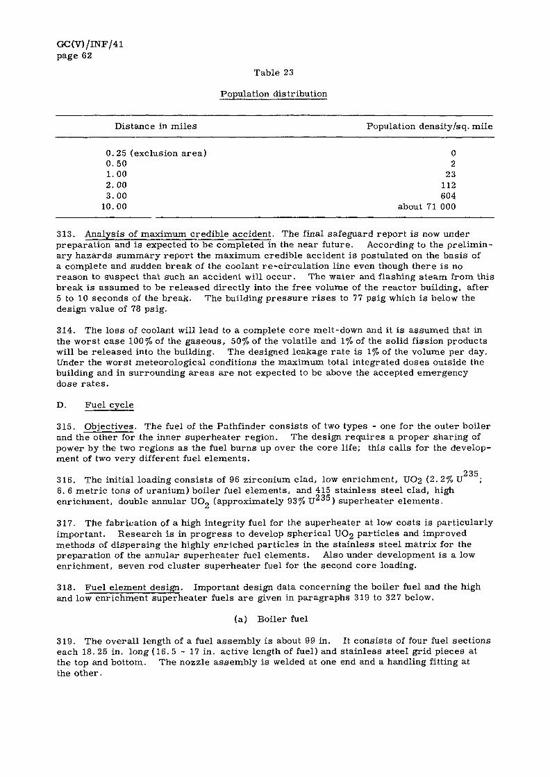
GC(V)/INF/41 page 62
Table 23
Population distribution
Distance in miles Population density/sq. mile
0.25 (exclusion area) 0 0.50 2 1.00 23 2.00 112 3.00 604
10.00 about 71 000
313. Analysis of maximum credible accident. The final safeguard report is now under preparation and is expected to be completed in the near future. According to the preliminary hazards summary report the maximum credible accident is postulated on the basis of a complete and sudden break of the coolant re-circulation line even though there is no reason to suspect that such an accident will occur. The water and flashing steam from this break is assumed to be released directly into the free volume of the reactor building, after 5 to 10 seconds of the break. The building pressure r i ses to 77 psig which is below the design value of 78 psig.
314. The loss of coolant will lead to a complete core melt-down and it is assumed that in the worst case 100% of the gaseous, 50% of the volatile and 1% of the solid fission products will be released into the building. The designed leakage rate is 1% of the volume per day. Under the worst meteorological conditions the maximum total integrated doses outside the building and in surrounding areas are not expected to be above the accepted emergency dose ra tes .
D. Fuel cycle
315. Objectives. The fuel of the Pathfinder consists of two types - one for the outer boiler and the other for the inner superheater region. The design requires a proper sharing of power by the two regions as the fuel burns up over the core life; this calls for the development of two very different fuel elements.
235 316. The initial loading consists of 96 zirconium clad, low enrichment, UO2 (2. 2% U 6. 6 metric tons of uranium) boiler fuel elements, and 415 stainless steel clad, high enrichment, double annular U0 2 (approximately 93% U 0 0 ) superheater elements.
317. The fabrication of a high integrity fuel for the superheater at low costs is particularly important. Research is in progress to develop spherical UO2 particles and improved methods of dispersing the highly enriched particles in the stainless steel matrix for the preparation of the annular superheater fuel elements. Also under development is a low enrichment, seven rod cluster superheater fuel for the second core loading.
318. Fuel element design. Important design data concerning the boiler fuel and the high and low enrichment superheater fuels are given in paragraphs 319 to 327 below.
(a) Boiler fuel
319. The overall length of a fuel assembly is about 99 in. It consists of four fuel sections each 18. 25 in. long (16. 5 - 17 in. active length of fuel) and stainless steel grid pieces at the top and bottom. The nozzle assembly is welded at one end and a handling fitting at the other.

GC(V)/INF/41 page 63
320. Each fuel section consists of 81 fuel rods, with threaded ends for joining the sections; in a 9 by 9 array. A stainless steel grid screen separates the fuel sections and provides rigidity and the proper spacing between rods. The fuel rod diameter is reduced in the upper two fuel sections from 0. 353 to 0. 315 in. inside diameter, to accommodate increasing steam-void volume.
321. The fuel rods are prepared by loading zirconium tubes (28 and 26 mills for the lower and upper sections, respectively) with pellets 1. 5 in. long and containing 2. 2% U2"", The two end pellets contain 1.8% dysprosium oxide as a buffer to smeeth out peaking at the interconnection of the fuel sections.
(b) High enrichment superheater fuel
322. The overall length of the fuel element including end pieces will be 78. 25 in. with a 72 in. fuel section. The fuel will consist of double annular cermet elements, 20 mils thick, containing 93% U " 5 dispersed in stainless steel and clad with 7. 5 mils of stainless steel. The center of the element will have a burnable poison rod with a diameter of approximately 0. 5 in. consisting of boron carbide in aluminium oxide. The burnable poison rod will be inserted in a 26 mils stainless steel tube.
323. The annular cermet fuel tubes will be fabricated by rolling the cermet plates and seam-welding to form the tubes. Straight wires will be used for spacers . The assembly of the inner and outer tubes will be performed by slightly deforming the outer tube into a triangle and then inserting the inner tube.
324. The completed fuel element will consist of the center burnable rod encased in a tube surrounded by a 50 mils steam space, the first fuel tube, a second steam space of 75 mils , the second fuel tube, a third steam space of 45 mils, a 15 mils stainless steel process tube, an insulating stagnant steam space of 25 mils, and finally a 26 mils tube.
325. The design of the element has been completed and it has been established that it is feasible to fabricate it. The techniques of fabrication are now being established, and an order is expected to be placed in the last quarter of 1961 for delivery early next year.
(c) Low enrichment superheater fuel
326. A low enrichment UO2 stainless steel clad, seven-rod cluster fuel is being developed for subsequent core loadings. These elements are designed to fit in the same process tubes as the initial loading. Work is proceeding on the swage compaction of the fuel rods, and methods of assemblying them.
327. The goal is the development of a fuel element capable of achieving a burn-up of 10 000 Mwd/t.
328. Fuel management. A contract has been concluded for the procurement of 142 boiler fuel elements: 110 of 2. 2% u 5 enrichment and 32 of 3. 2% for versatility during start-up and operation. About 90% of the pellets have been fabricated, and 20% of the zirconium tubing is in the process of acceptance. One-third of the boiler fuel is expected to be re-loaded every six months at 80% plant factor. The average expected exposure is 10 000 Mwd/t under equilibrium conditions.
235 329. A burn-up of 60 atom per cent of U or 1. 5 total atom per cent is the basis of the design which gives a fuel life of nine months. The superheater fuel will be subject to considerable research and development and a change will be made from the highly enriched tubular element to the low enrichment, seven rod cluster element after the first core.
E. Cost data
330. The following data were obtained for the reactor project:

GC(V)/INF/41 page 64
(a) Contract with reactor manufacturer Reactor plant Research and development
(b) USAEC contribution Research and development (maximum) Waiver of fuel use charge
(c) Excess operating cost during initial period
331. NSPC is capitalizing the cost of research and development incurred by the reactor manufacturer, or the total of the contract price of 22. 66 million, and they have given the unit capital cost as $450/kwe.
F. Operating personnel and training
332. The provisional staffing plan for the Pathfinder power plant is shown in Table 24 below, from which it will be seen that a total of 50 persons will run and maintain this plant.
Table 24
Pathfinder power plant: tentative staffing plan
TOTAL
TOTAL
Million $
19.01 3.65
22. 66
8.5 1.2
9. 7 1.2
Category Number of persons
Administration
Plant superintendent Assistant plant superintendent (L) Clerical staff
Operation
Nuclear engineer (L) Shift supervisors (L) Senior plant equipment operators (L) Plant equipment operators (L) Assistant plant equipment operators Plant attendants Radiation and chemical engineer Radiation safety technicians
Maintenance
Plant-results engineer Test engineers Instrument engineer Instrument technicians Station electrician Chemist Laboratory technicians Machinist Mechanic Repairmen Laborer
1 5 5 5 4 4 1 3
TOTAL 50
(L) Indicates licensed reactor operator.
GC(V)/INF/41 page 65
333. Most of the staff has been drawn from the steam plants of NSPC, and has prior experience in conventional plant operation. The plant superintendent has been working for utilities for 32 years including 20 years in the capacity of plant superintendent. He has received five months' training at Shippingport. The assistant plant superintendent has served as a results engineer in steam plants for ten years and has spent a year and a half at Argonne during which he received theoretical and practical experience in the operation of reactors . The nuclear engineer is a graduate in electrical engineering and nuclear physics and has worked for a year in the nuclear laboratory of the reactor designer and manufacturer at Greendale. The plant-results engineer has six years ' experience in his field of work; he attended the Shippingport school for six months and spent nine months at Greendale.
334. The radiation and chemical engineer was at Oak Ridge for nine years and has extensive experience in radiation protection techniques and regulations. He will be the health physicist for the plant and train the three radiation safety technicians who will work under him.
335. Each of the five shift supervisors has had ten years of experience or more in the same capacity in a conventional steam plant. They are currently undergoing comprehensive training consisting of a three months' basic course in reactor theory, six months' work at Greendale and six months' reactor operations at the Experimental and at the Material Test Reactors.
336. Each of the five senior plant equipment operators has had five years ' plant operating experience and their supplementary training comprises a three months' basic course in reactor theory, five months' practical work at Greendale and four months' reactor operations with CP-5.
337. Each of the five plant equipment operators has three to four years of operating experience. They will attend a three months' basic course in reactor theory and receive additional training at the plant.
338. All the shift supervisors and the senior and assistant plant equipment operators will participate in the criticality tests and critical power runs. They are required to obtain operators ' licenses before taking over the plant.
339. The four assistant plant equipment operators and. four plant attendants have not so far been selected.
340. The instrumentation engineer has ten years ' experience in the plants of NSPC and has spent five months at Savannah River. He will be assisted by three instrument men each having five yea r s ' experience in NSPC. They are being trained at the facilities of the instrumentation supplier.
341. The maintenance of the plant will be under the direction of the assistant plant superintendent who may have a junior engineer to help him. The maintenance staff consists of experienced machinists, mechanics and repair men.

GC(V)/INF/41 page 66
G. Selected references
342. A list of selected references concerning the Pathfinder power reactor is given below:
Pathfinder Atomic Power Plant, Safeguards Report, ACNP-5905, Allis-Chalmers Manufacturing Company, Milwaukee, Wis.
Allis-Chalmers Critical Facility, Preliminary Safeguards Report, ACNP-5R09, Allis-Chalmers Manufacturing Company, Milwaukee, Wis.
Pathfinder Atomic Power Plant, Technical Progress Report for 1 April -30 June 1959 , ACNP-5915, Allis-Chalmers Manufacturing Company, Milwaukee, Wis. (August 1959)
Boiling Water Reactor with Internal Superheater, Pathfinder Atomic Power Plant, Final Feasibility Report, ACNP-5917, Allis-Chalmers Manufacturing Company, Milwaukee, Wis. (August 1959)
Pathfinder Atomic Power Plant, Technical Progress Report for 1 July -30 September 1959 , ACNP-5924, Allis-Chalmers Manufacturing Company, Milwaukee, Wis. (February 1960)
Pathfinder Atomic Power Plant, Technical Progress Report for 1 October -31 December 1959, ACNP-6001, Allis-Chalmers Manufacturing Company, Milwaukee, Wis. (March 1960)
Pathfinder Atomic Power Plant, Technical Progress Report for 1 January -31 March 1960, ACNP-6006, Allis-Chalmers Manufacturing Company, Milwaukee, Wis. (June 1960)
Pathfinder Atomic Power Plant, Technical Progress Report for 1 April -30 June 1960 , ACNP-6007, Allis-Chalmers Manufacturing Company, Milwaukee, Wis. (October 1960)
Pathfinder Atomic Power Plant, Technical Progress Report for 1 July -30 September 1960, ACNP-6012, Allis-Chalmers Manufacturing Company, Milwaukee, Wis.
Pathfinder Atomic Power Plant, Technical Progress Report for 1 October -31 December 1960, ACNP-6102, Allis-Chalmers Manufacturing Company, Milwaukee, Wis. (April 1961)
BRAUN, C.R. , "Pathfinder and Nuclear Superheat", Conference of Atomic Power Engineering Group, Chicago, 111. (16 February 1961)
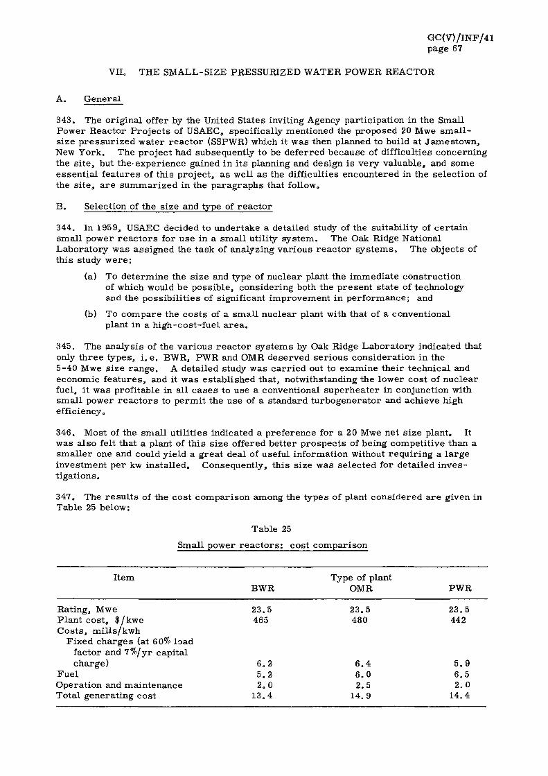
GC(V)/ INF/41 page 67
VII. THE SMALL-SIZE PRESSURIZED WATER POWER REACTOR
A. Genera l
343. The or ig ina l offer by the United States inviting Agency par t ic ipa t ion in the Small Power Reac tor P r o j e c t s of USAEC, specifically mentioned the proposed 20 Mwe s m a l l -s ize p r e s s u r i z e d wa te r r e a c t o r (SSPWR) which it was then planned to build at J a m e s t o w n , New York . The projec t had subsequently to be de fe r red because of difficulties concern ing the s i t e , but t he ' expe r i ence gained in i t s planning and design i s v e r y va luable , and some essen t i a l f ea tu res of th i s p ro jec t , a s well a s the difficulties encountered in the se lec t ion of the s i t e , a r e s u m m a r i z e d in the p a r a g r a p h s that follow.
B. Selection of the s ize and type of r e a c t o r
344. In 1959, USAEC decided to under take a detai led study of the sui tabil i ty of c e r t a i n sma l l power r e a c t o r s for use in a sma l l utili ty sy s t em. The Oak Ridge National Labora to ry was ass igned the t a sk of analyzing va r ious r e a c t o r s y s t e m s . The objects of th is study w e r e :
(a) To de te rmine the s ize and type of nuc lea r plant the immed ia t e cons t ruc t ion of which would be poss ib le , cons ider ing both the p re sen t s t a te of technology and the poss ib i l i t i e s of significant improvement in pe r fo rmance ; and
(b) To compare the c o s t s of a s m a l l nuc lea r plant with that of a conventional plant in a h igh-cos t - fue l a r e a .
345. The ana lys i s of the v a r i o u s r e a c t o r s y s t e m s by Oak Ridge Labo ra to ry indicated that only t h r e e types , i . e . BWR, PWR and OMR dese rved s e r i o u s cons idera t ion in the 5-40 Mwe s ize r a n g e . A detai led study w a s c a r r i e d out to examine the i r technica l and economic f e a t u r e s , and it was es tab l i shed that , notwithstanding the lower cos t of nuc lea r fuel, it was profi table in al l c a s e s to use a conventional supe rhea t e r in conjunction with sma l l power r e a c t o r s to pe rmi t the use of a s tandard tu rbogene ra to r and achieve high efficiency.
346. Most of the sma l l u t i l i t ies indicated a p re fe rence for a 20 Mwe net s ize plant . It was a l so felt that a plant of t h i s s ize offered be t t e r p r o s p e c t s of being compet i t ive than a s m a l l e r one and could y ie ld a g rea t deal of useful informat ion without r equ i r i ng a l a r g e inves tment pe r kw ins ta l l ed . Consequent ly, th i s s ize was se lec ted for detai led i n v e s t iga t ions .
347. The r e s u l t s of the cos t compar i son among the types of plant cons ide red a r e given in Table 25 below:
Table 25
Small power r e a c t o r s : cos t compar i son
I tem Type of plant BWR OMR PWR
Rat ing, Mwe 23.5 23 .5 23 .5 P lan t cos t , $ /kwe 465 480 442 C o s t s , m i l l s / k w h
Fixed c h a r g e s (at 60% load factor and 7%/yr capi ta l cha rge) 6 .2 6 .4 5 .9
Fue l 5 .2 6 .0 6 .5 Opera t ion and main tenance 2 . 0 2 .5 2 .0 Total genera t ing cost 13 .4 14 .9 14.4

GC(V)/INF/41 page 68
348. From the above comparison it was concluded that the estimated generating costs of the plants under study were very close, the differences being so small as to be well within the margin of uncertainty, and a PWR of 22 Mwe gross and 20 Mwe net output was selected for the project. Perhaps the overriding consideration in making this choice was that no plant of this type, using slightly enriched uranium was being built at the time under USAEC's Demonstration Power Reactor Program and it was felt that its construction would yield very useful information concerning small-size pressurized-water reac tors . Moreover, other types of small plants, such as the Elk River BWR and the Piqua OMR, were under construction and there was no great incentive to build a type of plant that would essentially duplicate the experience to be gained from these projects. Further , whereas other plants could offer good reliability, none could match the high degree of assurance of the PWR as a source of continuous supply in a small utility system. It has excellent load-following characteris t ics , there is a great deal of operating experience with this type, and its technology i s well established. There are no problems of radioactive carry-over as in the case of a direct cycle BWR, and it offers the possibility of achieving maximum fuel utilization through higher burn-ups.
349. After selecting the reactor size and type, USAEC invited applications from small publicly-owned utilities to supply the site and the turbogenerator, operate the plant for five years and buy steam from USAEC at a rate comparable with the cost incurred by them for producing from conventional plants in their own systems. As a result of screening a number of applications, the public utility of Jamestown, New York, was selected for the project.
C. Important design features
350. A conceptual study of the plant was then carried out, the principal objectives being to build on the basis of accepted technology the most economical power unit possible using equipment commercially available and with emphasis being placed on simplicity of operation and safety.
351. The conceptual study indicates that the plant is intended for base load operation and primary consideration is the production of power. Therefore, it is not designed to accommodate any experimental facility or serve any research and experimental program for the development of advanced reactor technology. It is not an experimental power plant. It is designed for reliable and continuous operation with the minimum of innovations and untried features.
352. To make the plant very safe, provisions are made for rapid injection of water into the core in the event of a loss of coolant accident and a core melt-down is not considered to be a credible accident. A unique feature of the plant is the use of an internal air r e circulation system which filters all the air in the containment shell every 11 minutes. An arrangement for water spray is also included to suppress the build-up of pressure and dissolve radioactive iodine, should there be any release of steam containing fission products. The reactor is housed in a containment shell to fully protect the surrounding areas from any possible radioactive hazard.
D. Difficulties in the selection of the site
353. The public utility of Jamestown offered a site near its existing conventional thermal station and about half a mile from the center of the town (population 45 000). The necessary supply of cooling water and other conventional requirements were available in the area, which from the point of view of the utility had an added advantage in that it would have enabled it to reduce total expenditure by using for the nuclear plant some of the services provided for the existing station.

GC(V)/INF/41 page 69
354. The conceptual study shows that in designing the reactor due note was taken of the fact that it would be built close to the town and great emphasis appears to have been placed on safety in reactor design and control. After necessary investigations around the site, the preliminary hazards analysis report was prepared and submitted to ACRS which, after careful review of the report felt that it could not approve the site because of its proximity to the populated area. At the same time, two other sites each about three miles from the city were considered acceptable by the committee.
355. Unless ACRS fully approves of a particular site USAEC does not consider it suitable. The utility was, therefore, asked to look into the possibility of using either of the two sites outside the town which were found acceptable by ACRS.
356. The company considered the possibility of shifting the reactor to one of these sites but the duplication of certain sub-station facilities and the provision of an additional t r ans mission line would have added to the total costs. Moreover since the sites were outside the city l imits, the utility would have had to pay a substantial amount to the county in taxes for the use of the land. Therefore, on economic grounds, it decided to withdraw its request for the reactor .
357. Another small utility in Wisconsin indicated an interest in the plant. In this case no problems arose over the site but the area served by the utility was provided with a good system of water transport, and the cost of conventional fuel was relatively low. This would have increased the disparity between the nuclear and conventional generating costs . The location of the plant at the Wisconsin site would consequently not have served one of the main objectives in building SSPWR, namely, to demonstrate that it could be possible for a small nuclear power station to be nearly competitive in a high-fuel-cost area.
E. Present position
358. The present position is that the project is currently being reconsidered by USAEC in the light of the interest expressed by another small utility in this reactor . It may, however, be necessary to modify the design objectives to suit a new site.
359. Continued interest in the reactor is based upon several considerations. For instance, the plant has been optimized for 20 Mwe and incorporates several attractive features to improve its competitive position in a high-cost-fuel area . It can no doubt yield technical and economic data of value to many countries besides the United States - especially the developing countries which have taken a keen interest in small and medium size plants.
360. The difficulties encountered in siting the reactor also emphasize the fact that the construction of a nuclear power plant close to a populated area may pose problems and in planning the installation of such a plant the problems of siting should not be underrated.
F . Selected references
361. A list of selected references concerning the small-size pressurized water power reactor is given below:
Task Force Evaluation Report - Small-sized Nuclear Power Plant Program, TID-8508, USAEC, Oak Ridge, Tenn. (October 1959)
Generating Cooperatives and Municipalities, Statistical Survey, TID-8509, USAEC, Oak Ridge, Tenn. (June 1959)
Survey of PWR Power Plants, 10 - 30 eMW Size, TID-8513, Alco Products, Inc . , Schenectady, N.Y. (October 1959)
GC(V)/INF/41 page 70
Small Size Pressurized Water Reactor Specifications, TID-8525, Gibbs and Hill, Inc. and Internuclear Co. Inc . , Clayton, Mo. (November 1959)
Small Size Pressurized Water Reactor Conceptual Design, TTD-8526, Gibbs and Hill, Inc. and Internuclear Co. Inc. , Clayton, Mo. (April 1960)
COPE, D. F . , and L.E GASSIE, W.A. , "History and Status of United States Small Power-Plant Program and Small Pressurized-Water Reactor Project", Small and Medium Power Reactors, v. 1. IAEA, Vienna (1961) p. 269

GC(V)/INF/41 page 71
VIII. THE EXPERIMENTAL LOW-POWER PROCESS HEAT REACTOR
A. General
362. ELPHR is a 30 - 40 Mwth experimental low-power process heat reactor of p ressur ized water type. Its construction at a suitable site is now under consideration as part of the USAEC program to demonstrate the technical and economic feasibility of a low temperature process heat reactor . Construction was actually authorized in 1959 and the estimated costs were above $4 million. At one time it was proposed to build it on the West Coast for desalinization of sea water by operating it as a steam source for the vacuum-flash evaporation distillation plant of the Department of the Interior. Because of certain administrative difficulties and other considerations connected with the site the proposal could not be carried out.
363. In response to an invitation from USAEC, four paper manufacturing companies in relatively high-cost-fuel areas have expressed an interest in participating in this project. It is envisaged that the selected organization should provide the site and facilities for the use of the steam, operate the entire plant for five years , and purchase the steam produced by the reactor . The reactor design will be based upon existing technology and the plant output will be 30 - 40 Mwth at steam pressures ranging from 15 - 200 psig. The project is scheduled for completion at the end of 1964.
B. Summary of technical aspects
364. Before selecting the size and type of this plant, an extensive survey was carried out of the requirements of process heat in the United States. The market survey indicated that the average size of a steam plant was about 10 Mwth - which was considered uneconomic for a nuclear reactor . Both on the basis of cost and technical considerations it was decided to optimize the reactor to 40 Mwth with a steam output of about 140 000 lbs /hr to give meaningful data which would be useful for designing future reac tors .
365. A comparison of three reactor types showed that in the light of the above considerations a pressurized-water reactor would be the most suitable. OMR was a close second and might even be better for applications requiring a higher steam temperature. BWR would have been favored if the steam could have been used directly from the reactor without having to employ an intermediate steam generator.
366. It has been estimated that nuclear reactors could become competitive with conventional process steam plants within the next ten years in the high-fuel-cost areas of the United States.
367. The design objectives of the ELPHR plant are;
(a) To construct a reactor on the basis of the current technology;
(b) To use a primary system of low-alloy steel fuel elements with a cladding of aluminum alloy, and the maximum amount of standard equipment; and
(c) To design a compact core.
368. It is expected that the operation of this reactor will yield very useful data of interest to processing industries and may lead to the possible use of nuclear power for desalinizing sea water.


GC(V)/INF/41 Annex I
ANNEX I
IMPORTANT DESIGN FEATURES OF THE ELK RIVER POWER REACTOR
Location
Owner/Operator
Type
Power
Gross thermal Electrical Over-all efficiency
Fuel element
Type
Fuel
Core
Dimensions Number of fuel elements Power density
P ressu re vessel
Control rods
Type Number
Containment shell
Turbine steam conditions
Temperature P ressu re Mass flow rate
Construction schedule
Start of construction Reactor critical Full power operation
Costs
Elk River, Minnesota
USAEC/RCPA
indirect cycle boiling-water reactor , with conventional fuel fired superheater
boiler: 58 Mw; superheater: net: 22 Mw 30.5%
14 Mw
25 rod clusters , SS cladding containing boron as burnable poison 4.3% U 2 3 5 , 0.3% U 2 3 8 , 95.4% Th; in form of dioxides
5 ft diameter, 5 ft high 148, room for 16 more 39 .6kw/ l
7 ft diameter, 25 ft high; carbon steel with SS cladding
cruciform 13
74 ft inside diameter, 115 ft high; steel plates, inside lined with concrete
825°F 620 psig 225 000 lb/hr
August 1958 October 1961 February 1962
approximately $10 million (excluding $600 000 for first fuel core and fuel development)


GC(V)/INF/41 Annex II
ANNEX II
IMPORTANT DESIGN FEATURES OF THE PIQUA NUCLEAR POWER FACILITY
Location
Owner/Operator
Type
Power
Gross thermal Electrical Over-all efficiency
Fuel element
Type Fuel
Core
Dimensions Number of fuel elements Power density
Pressure vessel
Control rods
Type Number
Containment shell
Turbine steam conditions
Temperature P res su re Mass flow rate
Construction schedule
Start of construction Reactor critical Full power operation
Costs
Piqua, Ohio
USAEC/City of Piqua
organic-moderated and cooled reactor
boiler: 45. 5 Mw gross: 12.5 Mw; net: 11.4 Mw 25.1%
two concentric tubes in aluminum cladding enrichment: 1.94% metal, alloyed with 3.5% Mo
4.8 ft diameter and 4. 5 ft high 85 19.4 kw/1
7 ft 8 in. inside diameter, 27 ft 3 in. over-all height, low carbon steel
tubular rods with boron carbide 13
73 ft diameter, 168 ft high, steel plates
550°F 435 psia 150 000 lb/hr
July 1959 November 1961 December 1961
$9.8 million

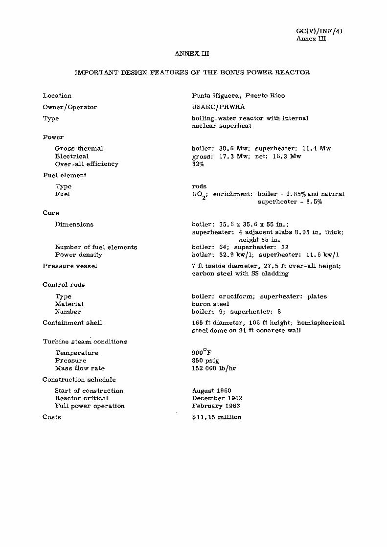
GC(V)/INF/41 Annex III
ANNEX HI
IMPORTANT DESIGN FEATURES OF THE BONUS POWER REACTOR
Location
Owner/Operator
Type
Power
Gross thermal Electrical Over-all efficiency
Fuel element
Type Fuel
Core
Dimensions
Number of fuel elements Power density
P ressu re vessel
Control rods
Type Material Number
Containment shell
Turbine steam conditions
Temperature P ressu re Mass flow rate
Construction schedule
Start of construction Reactor critical Full power operation
Punta Higuera, Puerto Rico
USAEC/PRWRA
boiling-water reactor with internal nuclear superheat
boiler: 38.6 Mw; superheater: 11.4 Mw gross: 17.3 Mw; net: 16.3 Mw 32%
rods U0 2 ; enrichment: boiler - 1.85% and natural
superheater - 3.5%
boiler: 35. 6 x 35. 6 x 55 in . ; superheater: 4 adjacent slabs 8.95 in. thick;
height 55 in. boiler: 64; superheater: 32 boiler: 32.9 kw/l; superheater: 11.6 kw/l
7 ft inside diameter, 27.5 ft over-all height; carbon steel with SS cladding
boiler: cruciform; superheater: plates boron steel boiler: 9; superheater: 8
165 ft diameter, 106 ft height; hemispherical steel dome on 24 ft concrete wall
900°F 850 psig 152 000 lb/hr
August 1960 December 1962 February 1963
Costs $11.15 million

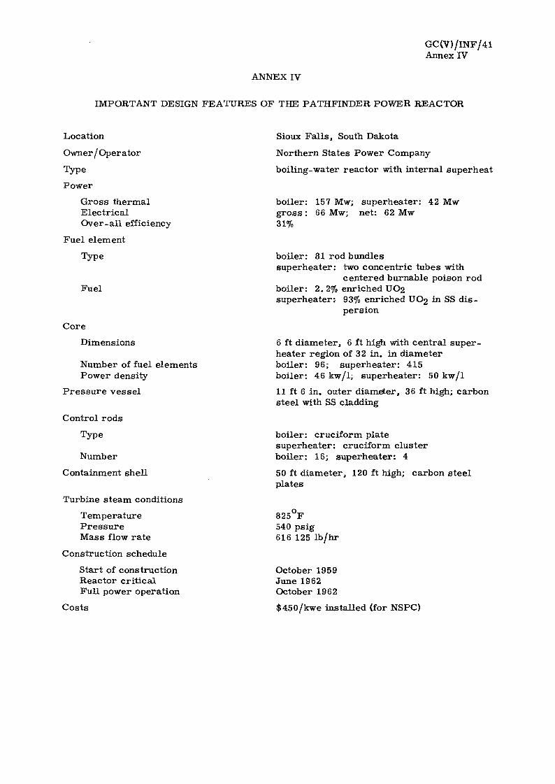
GC(V)/INF/41 Annex IV
ANNEX IV
IMPORTANT DESIGN FEATURES OF THE PATHFINDER POWER REACTOR
Location
Owner / Operator
Type
Power
Gross thermal Electrical
Over-all efficiency
Fuel element
Type
Fuel
Core
Dimensions
Number of fuel elements Power density
Pressure vessel
Control rods
Type
Number
Containment shell
Turbine steam conditions
Temperature Pressure Mass flow rate
Construction schedule
Start of construction Reactor critical Full power operation
Sioux Falls , South Dakota
Northern States Power Company
boiling-water reactor with internal superheat
boiler: 157 Mw; superheater: 42 Mw g ros s : 66 Mw; net: 62 Mw 31%
boiler: 81 rod bundles superheater; two concentric tubes with
centered burnable poison rod boiler: 2.2% enriched UO2 superheater; 93% enriched UO2 in SS dis
persion
6 ft diameter, 6 ft high with central superheater region of 32 in. in diameter boiler: 96; superheater: 415 boiler: 46 kw/l; superheater: 50 kw/1
11 ft 6 in. outer diameter, 36 ft high; carbon steel with SS cladding
boiler: cruciform plate superheater: cruciform cluster boiler: 16; superheater: 4
50 ft diameter, 120 ft high; carbon steel plates
825°F 540 psig 616 125 Ib/hr
October 1959 June 1962 October 1962
Costs $450/kwe instaHed (for NSPC)


SAFETY CONDENSER
506 F , 715 ps ia
2 STEAM GENERATORS
464°F
2 SUB-COOLERS
350°F
/ \ COAL-FIRED SUPERHEATER
825 F , 600 ps ig
14 Mwth
TURBINE -GENERATOR
22 Mwe
CONDENSER
>
225 000 l b / h r
FIGURE 1
SCHEMATIC FLOW DIAGRAM OF THE ELK RIVER POWER REACTOR
TO PURIFICATION FROM PURIFICATION

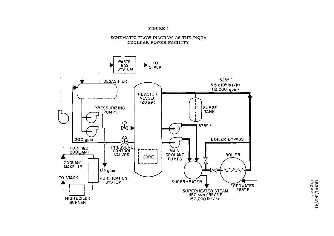
FIGURE 2
SCHEMATIC FLOW DIAGRAM OF THE PIQUA NUCLEAR POWER FACILITY
WASTE GAS
SYSTEM
TO STACK
525° F 5.5 x I0 6 lbs /hr (12,000 gpm)
HIGH BOILER BURNER
SUPERHEATED STEAM 4 5 0 p s i a / 5 5 0 ° F 150,000 Ibs/hr
FEEDWATER 268° F
fD


FIGURE 3
SIMPLIFIED SCHEMATIC DIAGRAM OF THE BONUS POWER REACTOR
MANUAL ROD
ELEMENT CONTROLLERS
^-a REACTOR PRESSURE
SUPERHEATING ZONES X
BOILING ZONE
MANUAL RECIRCULATING • WATER VALVE CONTROLLER
-a fr—
-H^H REFERENCE PRESSURE
PRESSURE GOVERNOR SELECTOR OR SPEED
T OESUPERHEATER
T
MINIMUM FLOW BY-PASS VALVE
RECIRCULATING WATER PUMPS
---? L* CONTROL
L TURBINE TRIP VALVE
t. TURBINE INLET VALVE
TURBINE BY PASS REGULATOR VALVE
C


FIGURE 4
SCHEMATIC DIAGRAM OF THE PATHFINDER POWER REACTOR
LIQUID WASTE TANK
• *ij.ilMRuJ.ilfBU"
w =h~i
Ca_ 7
~zz
-VENTILATION STACK
| 8 0 TON T 4 T .CRANE
FUEL STORAGE
POOL
SHIPPING CASK-
FUEL TRANSFER TUBE-
FUEL HANDLING BUILDING
REACTOR•
sarssfseBfOisfS*
DEMINERALIZED WATER TANK
A
LIT
A § §
=4*1-
MI
^ i fpw
•J PRECIPrTATOR TANKS
r±^ CLEARWELL
RECIRCULATION P ™ ^ PUMP
WATER TREATMENT BUILDING
era
REACTOR BUILDING