GB001- Introduction to protection by fuses - Sentridge … · GB001- INTRODUCTION TO PROTECTION BY...
26
GB001- INTRODUCTION TO PROTECTION BY FUSES Charles Mulertt - updated on 2006 – 02 Page 1 / 26 INTRODUCTION TO PROTECTION BY FUSES
Transcript of GB001- Introduction to protection by fuses - Sentridge … · GB001- INTRODUCTION TO PROTECTION BY...
GB001- INTRODUCTION TO PROTECTION BY FUSES Charles Mulertt - updated on 2006 – 02 Page 1 / 26
INTRODUCTION TO PROTECTION BY FUSES
GB001- INTRODUCTION TO PROTECTION BY FUSES Charles Mulertt - updated on 2006 – 02 Page 2 / 26
SUMMARY
1. PROTECTIONS AGAINST OVERCURRENTS ARE ABSOLUTELY NECESSARY
1.1. Overload 1.2. Short circuit 1.3. Consequences of overcurrents 1.4. Global convergence of legal considerations 1.5. Impact of legal considerations
2. ADVANTAGES OF THE FUSE
2.1. Safety 2.2. Speed 2.3. Breaking capacity 2.4. Maintenance before a short-circuit 2.5. Maintenance after a short-circuit 2.6. Selectivity (or discrimination) 2.7. Future system growth 2.8. Low power consumption 2.9. Reliability 2.10. Universal 2.11. Price
3. CONSTRUCTION OF A FUSE 4. INTERRUPTION OF OVER CURRENTS
4.1. Interruption of short circuit currents 4.2. Interruption of overloads
5. INTRODUCTION TO THE IEC 60269 STANDARD
5.1. IEC 60269 has four main chapters 5.2. There are two large family of fuses
6. TYPICAL LAY OUT OF A LARGE PRODUCTION PLANT (cem ent, pulp & paper, steel mill etc.) 7. SELECTION OF THE FUSE VOLTAGE RATING U N 8. CABLE PROTECTION 9. MOTOR CIRCUIT PROTECTION 10. POWER ELECTRONIC PROTECTION
10.1. Main criterions 10.2. Three phase bridge 10.3. Regenerative DC drive 10.4. Soft starters and static switches 10.5. Inverters 10.6. Multi-inverter system
11. FUSE OPERATION UNDER DC VOLTAGE
11.1. Comment on the fuse rated voltage – practical values of L / R 11.2. Example of DC capabilities for an ac rated fu se range 11.3. Fuse definition for a DC circuit protection
12. CONCLUSION
GB001- INTRODUCTION TO PROTECTION BY FUSES Charles Mulertt - updated on 2006 – 02 Page 3 / 26
1. PROTECTIONS AGAINST OVERCURRENTS ARE ABSOLUTELY NECESSARY There are 2 types of overcurrents:
• Overload • Short circuit
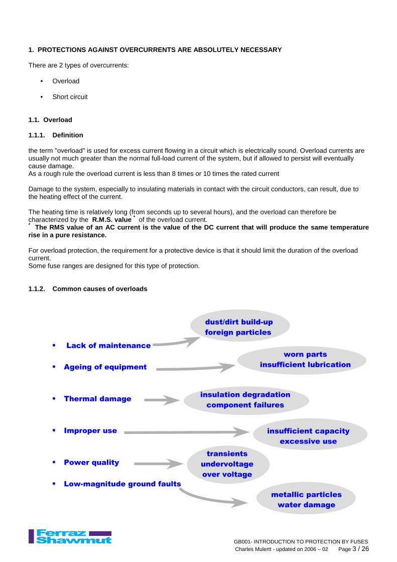
1.1. Overload 1.1.1. Definition the term "overload" is used for excess current flowing in a circuit which is electrically sound. Overload currents are usually not much greater than the normal full-load current of the system, but if allowed to persist will eventually cause damage. As a rough rule the overload current is less than 8 times or 10 times the rated current Damage to the system, especially to insulating materials in contact with the circuit conductors, can result, due to the heating effect of the current. The heating time is relatively long (from seconds up to several hours), and the overload can therefore be characterized by the R.M.S. value * of the overload current. * The RMS value of an AC current is the value of th e DC current that will produce the same temperature rise in a pure resistance. For overload protection, the requirement for a protective device is that it should limit the duration of the overload current. Some fuse ranges are designed for this type of protection. 1.1.2. Common causes of overloads
• Lack of maintenance
• Ageing of equipment
• Thermal damage
• Improper use
• Power quality
• Low-magnitude ground faults
dust/dirt build-up
foreign particles
worn parts
insufficient lubrication
insulation degradation
component failures
insufficient capacity
excessive use
transients
undervoltage
over voltage
metallic particles
water damage
GB001- INTRODUCTION TO PROTECTION BY FUSES Charles Mulertt - updated on 2006 – 02 Page 4 / 26
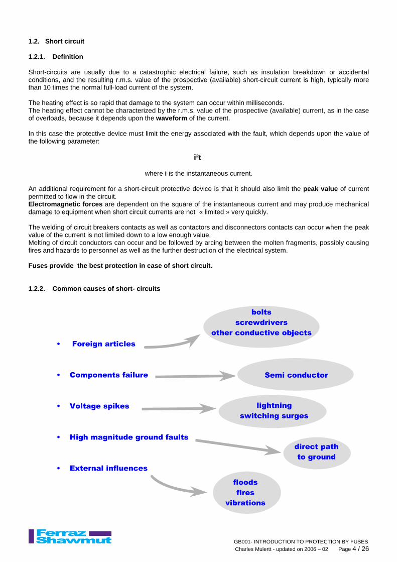
1.2. Short circuit 1.2.1. Definition Short-circuits are usually due to a catastrophic electrical failure, such as insulation breakdown or accidental conditions, and the resulting r.m.s. value of the prospective (available) short-circuit current is high, typically more than 10 times the normal full-load current of the system. The heating effect is so rapid that damage to the system can occur within milliseconds. The heating effect cannot be characterized by the r.m.s. value of the prospective (available) current, as in the case of overloads, because it depends upon the waveform of the current. In this case the protective device must limit the energy associated with the fault, which depends upon the value of the following parameter:
i²t
where i is the instantaneous current.
An additional requirement for a short-circuit protective device is that it should also limit the peak value of current permitted to flow in the circuit. Electromagnetic forces are dependent on the square of the instantaneous current and may produce mechanical damage to equipment when short circuit currents are not « limited » very quickly. The welding of circuit breakers contacts as well as contactors and disconnectors contacts can occur when the peak value of the current is not limited down to a low enough value. Melting of circuit conductors can occur and be followed by arcing between the molten fragments, possibly causing fires and hazards to personnel as well as the further destruction of the electrical system. Fuses provide the best protection in case of short circuit. 1.2.2. Common causes of short- circuits
• Foreign articles
• Components failure
• Voltage spikes
• High magnitude ground faults
• External influences
bolts
screwdrivers
other conductive objects
lightning
switching surges
direct path
to ground
floods
fires
vibrations
Semi conductor

GB001- INTRODUCTION TO PROTECTION BY FUSES Charles Mulertt - updated on 2006 – 02 Page 5 / 26
1.3. Consequences of overcurrents It is usually a combination of the following results !! 1.4. Global convergence of legal considerations
• Codes & Standards: harmonization... IEC, UL, NEC… • Product liability (legal precedents having worldwide impact) • New French law (98-388) holds manufacturers responsible for personnel & product liability for «less-than-
expected» product performance... disclaimers are null and void for users! 1.5. Impact of legal considerations
• Manufacturers are fully responsible for their components • OEM’s are fully responsible for their assemblies / equipment • «Limited liability» is a thing of the past! • Cost of settlements are growing astronomically! (personnel injury, equipment, downtime, mental anguish,
punitive damages)
• Injury
• Downtime
• Loss of process control
• Mechanical effect
• Thermal effect
- loss of life
- burns
- flash blindness
thousands of dollars
or euros per minute
- continuous process
- steel in arc furnace
- non-conforming parts
- equipment damage
- destruction from
magnetic movement
- equipment damage
- destruction from energy arcs
Figure 1 : danger of the arc flash energy

GB001- INTRODUCTION TO PROTECTION BY FUSES Charles Mulertt - updated on 2006 – 02 Page 6 / 26
2. FUSE ADVANTAGES 2.1. Safety
This is a key factor when designing or upgrading an installation. The fuse is still the best because: • The metallic element inside the fuse melts directly upon the fault current effect without any
intermediate mechanism , sensors etc …. • The arc extinction is totally enclosed so that there are no emission of gas, flames, arcs or other
materials when clearing the highest levels of short circuit currents. • FERRAZ SHAWMUT made a lot of tests demonstrating the arc flash energy is drastically reduced
when the peak current is limited by a fuse.
Maximized energy limitation = Minimized damage & in jury
2.2. Speed / peak let through current In case of large short circuit currents no other protection system is faster than the fuse . The consequence is that the peak current is limited down to low values by the fuse.
Fuses are then particularly suitable for circuit protection without damage to components involved in the fault circuit..
Figure 2 illustrates clearly the advantage of the speed of the fuse:
fuse = energy limitation and safe breaking operatio n 2.3. Breaking capacity
This is the largest current the fuse can interrupt. The fuse can provide values up to 100 000 A, 200 000 A and even 300 000 A.
2.4. Maintenance before a short-circuit
No maintenance is needed because the fuse characteristics do not change.
2.5. Maintenance after a short-circuit
After the interruption of the fault current it is necessary to replace the blown fuse by a new one. However this is done quickly and gives the insurance the equipments are still protected with exactly the same efficiency as before.
Current limiting circuit breaker
Figure 2: comparison of protective devices
i non-limiting circuit breaker
t
fuse
GB001- INTRODUCTION TO PROTECTION BY FUSES Charles Mulertt - updated on 2006 – 02 Page 7 / 26
2.6. Selectivity (or discrimination) 2.7. Future system growth
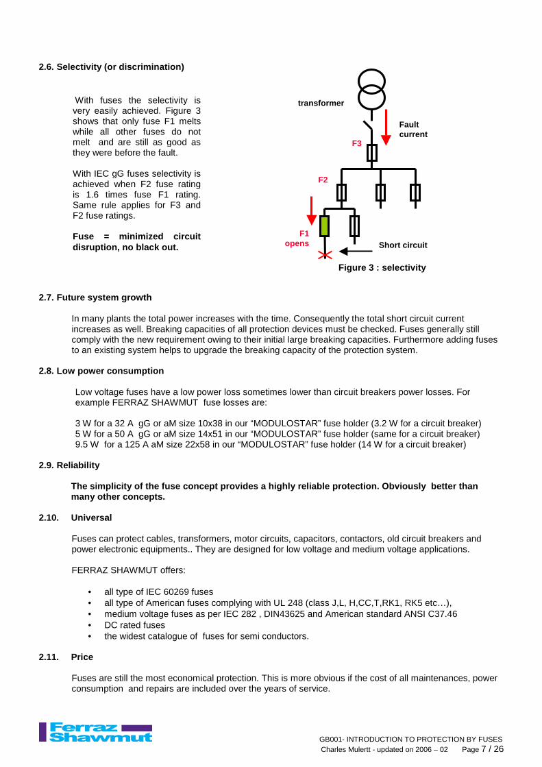
In many plants the total power increases with the time. Consequently the total short circuit current increases as well. Breaking capacities of all protection devices must be checked. Fuses generally still comply with the new requirement owing to their initial large breaking capacities. Furthermore adding fuses to an existing system helps to upgrade the breaking capacity of the protection system.
2.8. Low power consumption
Low voltage fuses have a low power loss sometimes lower than circuit breakers power losses. For example FERRAZ SHAWMUT fuse losses are: 3 W for a 32 A gG or aM size 10x38 in our “MODULOSTAR” fuse holder (3.2 W for a circuit breaker) 5 W for a 50 A gG or aM size 14x51 in our “MODULOSTAR” fuse holder (same for a circuit breaker) 9.5 W for a 125 A aM size 22x58 in our “MODULOSTAR” fuse holder (14 W for a circuit breaker)
2.9. Reliability
The simplicity of the fuse concept provides a highl y reliable protection. Obviously better than many other concepts.
2.10. Universal Fuses can protect cables, transformers, motor circuits, capacitors, contactors, old circuit breakers and power electronic equipments.. They are designed for low voltage and medium voltage applications. FERRAZ SHAWMUT offers:
• all type of IEC 60269 fuses • all type of American fuses complying with UL 248 (class J,L, H,CC,T,RK1, RK5 etc…), • medium voltage fuses as per IEC 282 , DIN43625 and American standard ANSI C37.46 • DC rated fuses • the widest catalogue of fuses for semi conductors.
2.11. Price
Fuses are still the most economical protection. This is more obvious if the cost of all maintenances, power consumption and repairs are included over the years of service.
transformer
F3
F2
F1opens
Figure 3 : selectivity
Short circuit
Fault current
With fuses the selectivity is very easily achieved. Figure 3 shows that only fuse F1 melts while all other fuses do not melt and are still as good as they were before the fault. With IEC gG fuses selectivity is achieved when F2 fuse rating is 1.6 times fuse F1 rating. Same rule applies for F3 and F2 fuse ratings. Fuse = minimized circuit disruption, no black out.

GB001- INTRODUCTION TO PROTECTION BY FUSES Charles Mulertt - updated on 2006 – 02 Page 8 / 26
3. CONSTRUCTION OF A FUSE Figure 1 shows the construction of a typical fuse. The fuse elements are usually made of pure silver strips or copper, with regions of reduced cross-sectional area (often called notches). There may be several strips in parallel, depending on the ampere rating of the fuse. They are enclosed within an insulating tube or ceramic body, which is filled with pure quartz sand. At each end there are terminals with a variety of designs to permit installation in fuse-holders or connection to busbars.
blade
body element sand
Figure 4: construction of a fuse
Body
contacts
Fuse elements fusibles
sand
Figure 5: fuse for semi conductor protection (PSC r ange)
Figure 6 : American Time Delay fuse with dual eleme nt construction for motor circuit protection

GB001- INTRODUCTION TO PROTECTION BY FUSES Charles Mulertt - updated on 2006 – 02 Page 9 / 26
GB001- INTRODUCTION TO PROTECTION BY FUSES Charles Mulertt - updated on 2006 – 02 Page 10 / 26
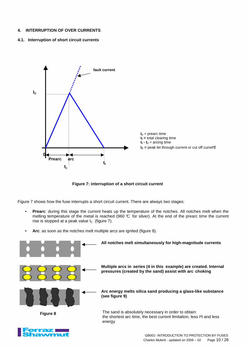
4. INTERRUPTION OF OVER CURRENTS 4.1. Interruption of short circuit currents Figure 7 shows how the fuse interrupts a short circuit current. There are always two stages:
• Prearc : during this stage the current heats up the temperature of the notches. All notches melt when the melting temperature of the metal is reached (960 °C for silver). At the end of the prearc time the current rise is stopped at a peak value IC (figure 7).
• Arc : as soon as the notches melt multiple arcs are ignited (figure 8).
The sand is absolutely necessary in order to obtain: the shortest arc time, the best current limitation, less I²t and less energy
tp = prearc time t t = total clearing time t t - tp = arcing time IC = peak let through current or cut off current
Figure 7: interruption of a short circuit current
Prearc arc
tp
t t
fault current
0
IC
All notches melt simultaneously for high -magnitude currents Multiple arcs in series (4 in this example) are created. Internal pressures (created by the sand) assist with arc choking
Arc energy melts silica sand producing a glass-like substance (see figure 9)
Figure 8
GB001- INTRODUCTION TO PROTECTION BY FUSES Charles Mulertt - updated on 2006 – 02 Page 11 / 26
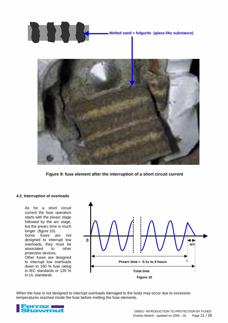
4.2. Interruption of overloads When the fuse is not designed to interrupt overloads damaged to the body may occur due to excessive temperatures reached inside the fuse before melting the fuse elements.
arc
t
0
Prearc time = 0.1s to 4 hours
Total time
Figure 10
As for a short circuit current the fuse operation starts with the prearc stage followed by the arc stage, but the prearc time is much longer (figure 10). Some fuses are not designed to interrupt low overloads, they must be associated to other protective devices. Other fuses are designed to interrupt low overloads down to 160 % fuse rating in IEC standards or 135 % in UL standards.
Figure 9: fuse element after the interruption of a short circuit current
Melted sand = fulgurite (glass -like substance)

GB001- INTRODUCTION TO PROTECTION BY FUSES Charles Mulertt - updated on 2006 – 02 Page 12 / 26
5. INTRODUCTION TO THE IEC 60269 STANDARD 5.1. IEC 60269 has four main chapters
5.2. There are two large family of fuses: “ a “ type fuses: designed for short circuits only, they are not able to interrupt low overloads. They have a “ partial “ operating range. “ g “ type fuses: designed to interrupt overloads and short circuits. They have a full operating range
FUSE TYPE TYPICAL INDUSTRIAL APPLICATIONS OPERATING RANGE
aM Motor circuits protection against short circuit only
aR IEC 269-4 fuse for semi conductor protection PARTIAL RANGE
gG General purpose fuse essentially for conductor protection
gM Motor protection
gN North American fast acting fuse for general purpose applications, mainly for conductor protection. As per UL 248 class J and class L fuses.
gD North American general purpose time-delay fuse for motor circuit protection and conductor protection (for example: fuse class AJT, RK5 and A4BQ)
gTR Transformer protection
gR, gS IEC 269-4 semi conductor protection and conductor protection
gL, gF, gI Former type of fuses for conductor protection replaced today by the gG fuses
FULL RANGE
IEC 60269-1 Low-voltage fuses
1000 V ac & 1500 V dc IEC 60269-2
Systems for use by authorized persons
(industrial application)
IEC 60269-4 Systems for the
protection of semiconductor devices
IEC 60269-3 Systems for use by unskilled persons
(household applications)
CEI 60269-3-1
Section I : Neozed & Diazed Section IIA : NF 6A 6,2 x 22,2 - 10A 8,4 x 22,2 16A 10,2 x 25,4 - 20A 8,4 x 31 25A 10,2 x 31 - 32A 10,2 x3 7,4 Section IIB : BS 1361 Section IIC : type C (Italy) Section III : pin-type fuses Section IV : fuses in plugs ( BS 1362)
IEC 60269-4-1 Examples of types: BS88, USA, DIN etc…
General
Domestic usage As per type and
country rules industrial usage - general cables and motors protection
Specific usage Voltages can go above 1000 V ac & 1500 V dc
CEI 60269-2-1 Section I : NH system Section II : BS88 Section III: 10x38,14x51,22x58 Section IV: BS88 Offset blades Section V : UL 248 Class J & class L

GB001- INTRODUCTION TO PROTECTION BY FUSES Charles Mulertt - updated on 2006 – 02 Page 13 / 26
5.3. Typical IEC curves Full range and partial range operation are illustra ted in figure 11
Figure 11: comparison of the time current curve of 4 different IEC fuses rated 100 A
Class aR (partial range fuse) for semi-conductor protection
Class aM fuse (Partial range fuse) or back up fuse for motor circuit protection
Class gR (full range fuse) for conductor and semi-conductor protection
Class gG (full range fuse) or general purpose fuse essentially for conductor protection
Temperature rise test station rated 4000 A

GB001- INTRODUCTION TO PROTECTION BY FUSES Charles Mulertt - updated on 2006 – 02 Page 14 / 26
6. TYPICAL GENERAL LAY OUT OF A LARGE PRODUCTION PL ANT (cement, pulp & paper, steel mill etc.)
Medium voltage : 4.16 KV, or 6.6 KV or 7.2 KV etc.
Medium voltage fuses
Compressors Fans etc.
High voltage (above 36 KV)
Low voltage gG fuse Low
voltage gG fuse
Low voltage aM fuse
UPS
Medium voltage generator
Medium voltage low voltage transformer
High voltage Medium voltage Transformer
G
Lighting
Low voltage aM fuse
AC drive
Soft starter
DC drive
Low voltage gG fuse
DC motor
DC fuse
Semiconductor fuses URD, gRB, gRC etc.
Figure 12
GB001- INTRODUCTION TO PROTECTION BY FUSES Charles Mulertt - updated on 2006 – 02 Page 15 / 26
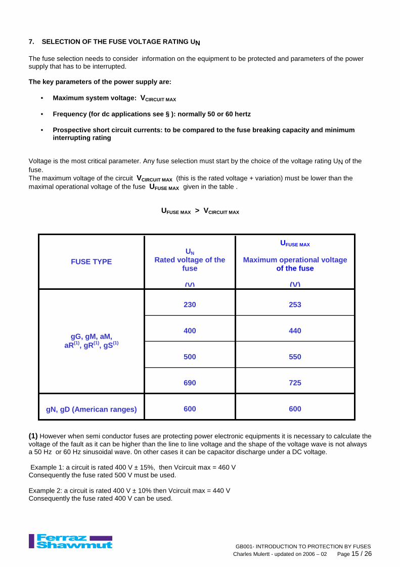
7. SELECTION OF THE FUSE VOLTAGE RATING U N The fuse selection needs to consider information on the equipment to be protected and parameters of the power supply that has to be interrupted. The key parameters of the power supply are:
• Maximum system voltage: VCIRCUIT MAX • Frequency (for dc applications see § ): normally 50 or 60 hertz
• Prospective short circuit currents: to be compared to the fuse breaking capacity and minimum
interrupting rating Voltage is the most critical parameter. Any fuse selection must start by the choice of the voltage rating UN of the fuse. The maximum voltage of the circuit VCIRCUIT MAX (this is the rated voltage + variation) must be lower than the maximal operational voltage of the fuse UFUSE MAX given in the table .
UFUSE MAX > VCIRCUIT MAX (1) However when semi conductor fuses are protecting power electronic equipments it is necessary to calculate the voltage of the fault as it can be higher than the line to line voltage and the shape of the voltage wave is not always a 50 Hz or 60 Hz sinusoidal wave. 0n other cases it can be capacitor discharge under a DC voltage. Example 1: a circuit is rated 400 V ± 15%, then Vcircuit max = 460 V Consequently the fuse rated 500 V must be used. Example 2: a circuit is rated 400 V ± 10% then Vcircuit max = 440 V Consequently the fuse rated 400 V can be used.
600
600
gN, gD (American ranges)
725
690
550
500
440
400
253
230
gG, gM, aM, aR(1), gR(1), gS(1)
UFUSE MAX
Maximum operational voltage
of the fuse
(V)
UN
Rated voltage of the fuse
(V)
FUSE TYPE

GB001- INTRODUCTION TO PROTECTION BY FUSES Charles Mulertt - updated on 2006 – 02 Page 16 / 26
8. CABLE PROTECTION After the voltage rating selection as explained in § 7, the protection of the cable is checked with the following parameters:
IB : operating current of the cable IZ : maximum current carrying capacity of the cable IN : rated current of the gG style fuse IF : conventional fusing current of the fuse
The cable is protected when the 2 following conditions are fulfilled: The choice of the fuse is made after :
• calculation of the acceptable current in the conduc tors • determination of the number of conductors according to the installation method • correction when the temperature inside the cubicle is above 40°C (fuse is derated) • correction when there is a forced air cooling (it h elps the fuse to carry more current)
The fuses have to be fitted at the starting point o f the circuit to be protected 9. MOTOR CIRCUIT PROTECTION The aM fuse must be associated to other protective devices because it must not operate for times above 60 seconds
Tables with selected fuses are supplied. Tables on the next page are valid only for 1500 RPM asynchronous motors. Other tables giving a correction factor versus RPM value and power are available. But it is necessary to check:
• correction when the temperature inside the cubicle is above 40°C (fuse is derated) • correction when there is a forced air cooling (it h elps the fuse to carry more current)
ZNB III ≤≤≤≤≤≤≤≤
ZF I1.45I ≤≤≤≤
t
Motor damage curve
Current-limiting fuse
Thermal relay 60 s
i Figure 13

GB001- INTRODUCTION TO PROTECTION BY FUSES Charles Mulertt - updated on 2006 – 02 Page 17 / 26
1500 RPM three phase asynchronous motor
660 V 220 V 380 V 220 V
Selected fuses: class, voltage rating and current rating
380 V
660 V
1500 RPM three phase asynchronous motor
660 V 220 V 380 V 220 V
Selected fuses: class, voltage rating and current rating
380 V
660 V
GB001- INTRODUCTION TO PROTECTION BY FUSES Charles Mulertt - updated on 2006 – 02 Page 18 / 26
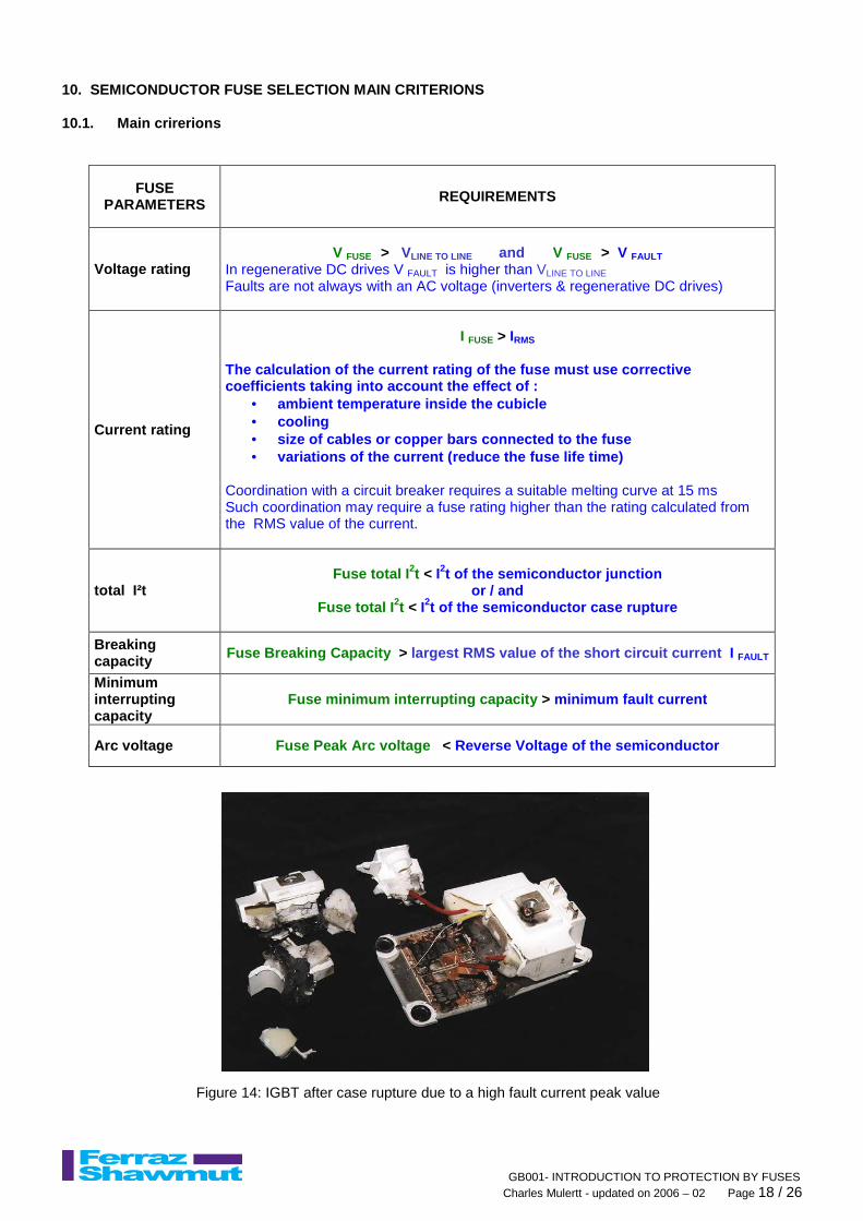
10. SEMICONDUCTOR FUSE SELECTION MAIN CRITERIONS 10.1. Main crirerions
FUSE PARAMETERS REQUIREMENTS
Voltage rating V FUSE > VLINE TO LINE and V FUSE > V FAULT
In regenerative DC drives V FAULT is higher than VLINE TO LINE Faults are not always with an AC voltage (inverters & regenerative DC drives)
Current rating
I FUSE > IRMS
The calculation of the current rating of the fuse m ust use corrective coefficients taking into account the effect of :
• ambient temperature inside the cubicle • cooling • size of cables or copper bars connected to the fuse • variations of the current (reduce the fuse life tim e)
Coordination with a circuit breaker requires a suitable melting curve at 15 ms Such coordination may require a fuse rating higher than the rating calculated from the RMS value of the current.
total I²t Fuse total I 2t < I2t of the semiconductor junction
or / and Fuse total I 2t < I2t of the semiconductor case rupture
Breaking capacity Fuse Breaking Capacity > largest RMS value of the short circuit current I FAULT
Minimum interrupting capacity
Fuse minimum interrupting capacity > minimum fault current
Arc voltage Fuse Peak Arc voltage < Reverse Voltage of the semiconductor
Figure 14: IGBT after case rupture due to a high fault current peak value
GB001- INTRODUCTION TO PROTECTION BY FUSES Charles Mulertt - updated on 2006 – 02 Page 19 / 26
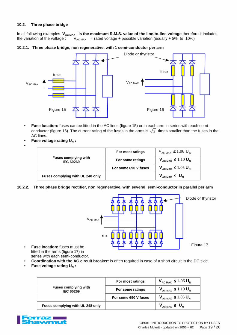
10.2. Three phase bridge In all following examples VAC MAX is the maximum R.M.S. value of the line-to-line voltage therefore it includes the variation of the voltage : VAC MAX = rated voltage + possible variation (usually + 5% to 10%) 10.2.1. Three phase bridge, non regenerative, with 1 semi-conductor per arm
• Fuse location: fuses can be fitted in the AC lines (figure 15) or in each arm in series with each semi-conductor (figure 16). The current rating of the fuses in the arms is 2 times smaller than the fuses in the AC lines.
• Fuse voltage rating U N : •
For most ratings NMAXAC U06.1V ≤
For some ratings NMAXAC U.V 101≤≤≤≤ Fuses complying with IEC 60269
For some 690 V fuses NMAXAC U.V 051≤≤≤≤
Fuses complying with UL 248 only NMAXAC UV ≤≤≤≤
10.2.2. Three phase bridge rectifier, non regener ative, with several semi-conductor in parallel per arm
• Fuse location: fuses must be fitted in the arms (figure 17) in series with each semi-conductor.
• Coordination with the AC circuit breaker: is often required in case of a short circuit in the DC side. • Fuse voltage rating U N :
For most ratings NMAXAC U.V 061≤≤≤≤
For some ratings NMAXAC U.V 101≤≤≤≤ Fuses complying with IEC 60269
For some 690 V fuses NMAXAC U.V 051≤≤≤≤
Fuses complying with UL 248 only NMAXAC UV ≤≤≤≤
VAC MAX
Figure 15
fuse
Diode or thyristor
VAC MAX
Figure 16
fuse
Figure 17
Diode or thyristor
VAC MAX
fus
GB001- INTRODUCTION TO PROTECTION BY FUSES Charles Mulertt - updated on 2006 – 02 Page 20 / 26
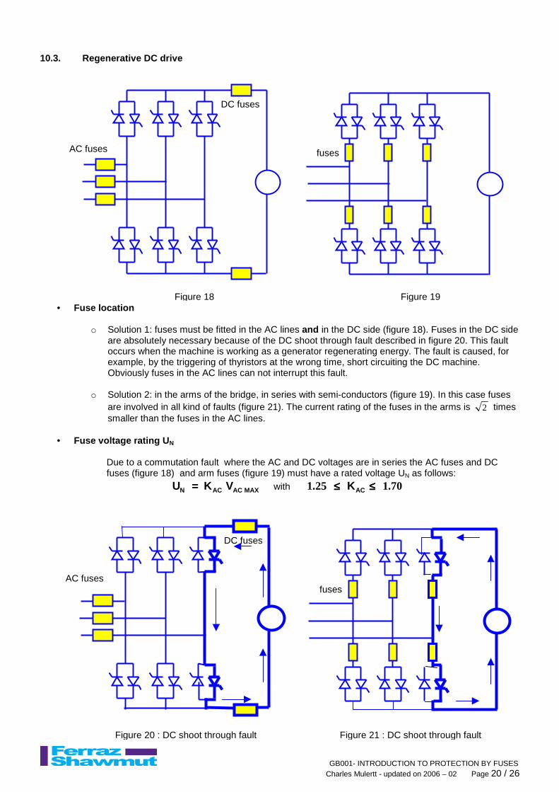
10.3. Regenerative DC drive
• Fuse location
o Solution 1: fuses must be fitted in the AC lines and in the DC side (figure 18). Fuses in the DC side are absolutely necessary because of the DC shoot through fault described in figure 20. This fault occurs when the machine is working as a generator regenerating energy. The fault is caused, for example, by the triggering of thyristors at the wrong time, short circuiting the DC machine. Obviously fuses in the AC lines can not interrupt this fault.
o Solution 2: in the arms of the bridge, in series with semi-conductors (figure 19). In this case fuses
are involved in all kind of faults (figure 21). The current rating of the fuses in the arms is 2 times smaller than the fuses in the AC lines.
• Fuse voltage rating U N
Due to a commutation fault where the AC and DC voltages are in series the AC fuses and DC fuses (figure 18) and arm fuses (figure 19) must have a rated voltage UN as follows:
MAXACACN V K U ==== with 701251 .K. AC ≤≤≤≤≤≤≤≤
Figure 18
AC fuses
DC fuses
Figure 19
fuses
Figure 21 : DC shoot through fault
fuses
Figure 20 : DC shoot through fault
AC fuses
DC fuses
GB001- INTRODUCTION TO PROTECTION BY FUSES Charles Mulertt - updated on 2006 – 02 Page 21 / 26
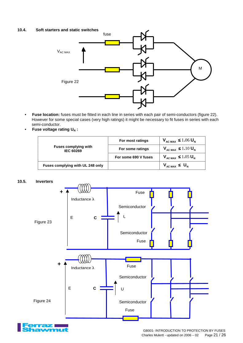
10.4. Soft starters and static switches
• Fuse location: fuses must be fitted in each line in series with each pair of semi-conductors (figure 22). However for some special cases (very high ratings) it might be necessary to fit fuses in series with each semi-conductor.
• Fuse voltage rating U N :
For most ratings NMAXAC U.V 061≤≤≤≤
For some ratings NMAXAC U.V 101≤≤≤≤ Fuses complying with IEC 60269
For some 690 V fuses NMAXAC U.V 051≤≤≤≤
Fuses complying with UL 248 only NMAXAC UV ≤≤≤≤
10.5. Inverters
M
fuse I
VAC MAX
Figure 22
Figure 23
Inductance λ
C E U
+
-
Semiconductor
Fuse
Fuse
Semiconductor
Figure 24
Inductance λ
C E U
+
-
Semiconductor
Fuse
Fuse
Semiconductor

GB001- INTRODUCTION TO PROTECTION BY FUSES Charles Mulertt - updated on 2006 – 02 Page 22 / 26
• Fuse location: 2 possibilities :
o fuses in the arms of the inverter (figure 23) o fuses in the DC loop of the inverter (figure 24): note, in this case, the fuse current rating is 1.7
times the current rating of the fuse in the arms
• Fuse voltage rating U N :
the fuse will interrupt the capacitor discharge current generated by the short circuit created by the failure or bad triggering of semiconductors (figures 25 & 26). The fuse selection is based on the knowledge of the fuse maximum DC voltage rating at time constants lower than 1 ms (L/R < 1 millisecond).
Figure 25
Inductance λ
C E U
+
-
Semiconductor
Fuse
Fuse
Semiconductor
Figure 26
Inductance λ
C E U
+
-
Semiconductor
Fuse
Fuse
Semiconductor

GB001- INTRODUCTION TO PROTECTION BY FUSES Charles Mulertt - updated on 2006 – 02 Page 23 / 26
10.6. Multi-Inverters system
• Fuse location:
o fuses in the feeder of each inverter (figure 27)
• Fuse voltage rating U N :
the fuse will interrupt the capacitor discharge currents from all capacitors in all other feeders (they are in parallel) and the DC current supplied by the DC power source. The fuse selection is based on the knowledge of the fuse maximum DC voltage rating at time constants lower than 1 ms (L/R < 1 millisecond).
DC power source (Battery or rectifier
or fuel cell or photovoltaic
etc …)
MAIN DC BUS BAR
N inverters feeding 3-phase machines
+ - Inverter 1
DC
AC
M VDC
VDC
Inverter N
DC
AC
M VDC
Figure 27
Inverter 2
DC
AC
M VDC
GB001- INTRODUCTION TO PROTECTION BY FUSES Charles Mulertt - updated on 2006 – 02 Page 24 / 26
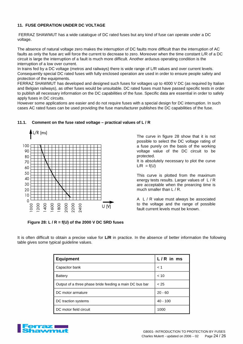
11. FUSE OPERATION UNDER DC VOLTAGE FERRAZ SHAWMUT has a wide catalogue of DC rated fuses but any kind of fuse can operate under a DC voltage. The absence of natural voltage zero makes the interruption of DC faults more difficult than the interruption of AC faults as only the fuse arc will force the current to decrease to zero. Moreover when the time constant L/R of a DC circuit is large the interruption of a fault is much more difficult. Another arduous operating condition is the interruption of a low over current. In trains fed by a DC voltage (metros and railways) there is wide range of L/R values and over current levels. Consequently special DC rated fuses with fully enclosed operation are used in order to ensure people safety and protection of the equipments. FERRAZ SHAWMUT has developed and designed such fuses for voltages up to 4000 V DC (as required by Italian and Belgian railways), as other fuses would be unsuitable. DC rated fuses must have passed specific tests in order to publish all necessary information on the DC capabilities of the fuse. Specific data are essential in order to safely apply fuses in DC circuits. However some applications are easier and do not require fuses with a special design for DC interruption. In such cases AC rated fuses can be used providing the fuse manufacturer publishes the DC capabilities of the fuse. 11.1. Comment on the fuse rated voltage – practical values of L / R
It is often difficult to obtain a precise value for L/R in practice. In the absence of better information the following table gives some typical guideline values.
Equipment L / R in ms
Capacitor bank < 1
Battery < 10
Output of a three phase bride feeding a main DC bus bar < 25
DC motor armature 20 - 60
DC traction systems 40 - 100
DC motor field circuit 1000
Figure 28: L / R = f(U) of the 2000 V DC SRD fuses
The curve in figure 28 show that it is not possible to select the DC voltage rating of a fuse purely on the basis of the working voltage value of the DC circuit to be protected. It is absolutely necessary to plot the curve L/R = f(U) This curve is plotted from the maximum energy tests results. Larger values of L / R are acceptable when the prearcing time is much smaller than L / R. A L / R value must always be associated to the voltage and the range of possible fault current levels must be known.
GB001- INTRODUCTION TO PROTECTION BY FUSES Charles Mulertt - updated on 2006 – 02 Page 25 / 26
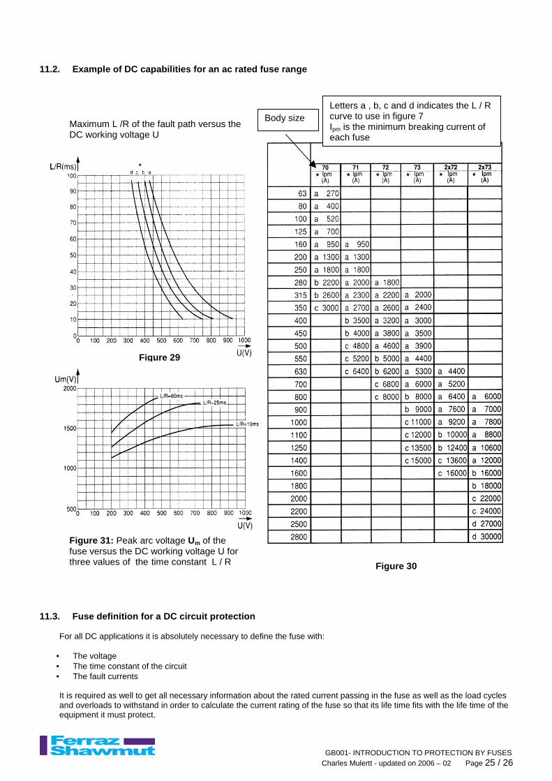
11.2. Example of DC capabilities for an ac rated fu se range
11.3. Fuse definition for a DC circuit protection
For all DC applications it is absolutely necessary to define the fuse with:
• The voltage • The time constant of the circuit • The fault currents It is required as well to get all necessary information about the rated current passing in the fuse as well as the load cycles and overloads to withstand in order to calculate the current rating of the fuse so that its life time fits with the life time of the equipment it must protect.
Figure 29
Figure 30
Letters a , b, c and d indicates the L / R curve to use in figure 7 Ipm is the minimum breaking current of each fuse
Maximum L /R of the fault path versus the DC working voltage U
Figure 31: Peak arc voltage Um of the fuse versus the DC working voltage U for three values of the time constant L / R
Body size

GB001- INTRODUCTION TO PROTECTION BY FUSES Charles Mulertt - updated on 2006 – 02 Page 26 / 26
12. CONCLUSION Alone or associated to other protection devices the fuse is an ideal solution for the protectionof:
• Low voltage distribution circuits • Medium voltage distribution circuits • Power electronic equipments • Low voltage and medium voltage DC circuits
F
U
S
E
Full overcurrent protection, Fidelity of operation
Universal use (gM or gD ideal all-purpose fuse)
Selectivity, Simplicity, Safety
Economical, Energy-limiting, Easy-to-use
Simply perfect !