GB ECLISSE Motor Drive System ECLIS 5
16
INSTRUCTIONS FOR COMMISSIONING THE ECLIS 5-L EC_MAN_ IST _ 010 Rev. 0 ECLISSE Motor Drive System ECLIS 5 GB
Transcript of GB ECLISSE Motor Drive System ECLIS 5

INSTRUCTIONS FOR COMMISSIONING THE ECLIS 5 - L
EC_MAN_ IST _ 010
Rev. 0
ECLISSE Motor Drive System ECLIS 5GB

INSTRUCTIONS FOR COMMISSIONING THE ECLIS 5 - L
EC_MAN_ IST _ 010
Rev. 0
2 di 16
DECLARATION OF CONFORMITY (Direttiva Macchine 98/37/CE, Allegato II, parte A)
Eclisse s.r.l. Via Sernaglia, 76 31053 Pieve di Soligo (TV) Tel. +39 0438 980513 – Fax.+39 0438 980804 [email protected] – www.eclisse.it
Declare that:
Desciption : Motorisation ECLIS 5
⌧ Conforms to the Machinery Directive 98/37/CE. ⌧ Conforms to the following Norms
Date: 10/11/2009
Signature of the person legally responsible:

INSTRUCTIONS FOR COMMISSIONING THE ECLIS 5 - L
EC_MAN_ IST _ 010
Rev. 0
3 di 16
Index
General Instructions and Warnings............................................................. Pag. 4
Parts List …………………………………………………………………………. Pag. 5
Technical Specifications…………..…………………………………….……… Pag. 6
Tensioning the Spring.................................................................................. Pag 6
Installation Lay-Out Single …………………………………………………….. Pag. 7
Installation Lay-Out Double ……….…………………………………………… Pag. 8
Electrical Diagrams – Transformer...........……………………………………. Pag. 9
Electrical Diagram – Circuit Board…………………………………………….. Pag. 10
Electrical Connections………………………………………………………….. Pag. 11
Positioning the Door/s Prior to Start Up………………………………………. Pag. 12
Starting Proceedure…………………………………………………………….. Pag. 13
Checks …………………………………………………………………………… Pag. 14
Optionals ………………………………………………………………………… Pag. 15
Troubleshooting ………………………………………………………………… Pag. 16

INSTRUCTIONS FOR COMMISSIONING THE ECLIS 5 - L
EC_MAN_ IST _ 010
Rev. 0
4 di 16
GENERAL INSTRUCTIONS
• The basic system comprises of a motor driven track system with a circuit board and
transformer in a Gweiss type box.
• This system can be controlled by a number of devices such as infra red radar,
photocells, remote control or push button. In some cases we will supply these but
they can also be supplied by others. We cannot accept any responsibility for the
installation and use of third party controls.
• In ALL installations this system must be protected from the mains by a suitably
sized isolation switch and there must be a push button/push switch installed near to
the door/s. As these switches differ from country to country, we do not supply them
with the system. The push button/push switch can be used to open and close the
door/s but is essential for reactivating the system should there be a power cut.
• There are separate instructions for physically installing the motor, circuit board and
door, please ensure these are followed carefully and the door/s are completely free
running with no obstructions whatsoever. Check particularly that the doors are not
rubbing along the guides or floor - this is important as it would falsify the self
calibration of the system and cause it to function badly if at all.
WARNINGS
• This system must be installed by a suitable qualified person with experience of access
control and in accordance with all local regulations.
• Ensure the installer has read and understood the complete manual.
• During the installation, connection and any modifications the electrical supply must be
disconnected.
• This system must be protected from the mains by an isolation switch, suitably sized and
must be used each and every time any electrical connections are made or modified.
• The circuit board and transformer are supplied inside the Gweiss box and for ease of
connection should be removed by releasing the re-usable tie cables. Be careful not to
cause any damage when doing this.
GB
GB

INSTRUCTIONS FOR COMMISSIONING THE ECLIS 5 - L
EC_MAN_ IST _ 010
Rev. 0
5 di 16
PARTS LIST
Qty 2 2 2 2 1 1
Des
crip
tion
Bolt
M8x
40Fl
atW
ashe
rN
utM
8lo
wpr
ofile
M8
Run
ners
Pulle
yEn
dSt
op
No. 25 26 27 28 29 30
Qty 1 1 1 1 1 1 1 1 1 1 1 1
Des
crip
tion
Tens
ion
Dev
ice
Stop
fort
ensi
onde
vice
Scre
ws
M5x
20ZN
BTr
actio
nsp
ring
Belt
stop
DX
Belt
stop
SX
Ret
urn
pulle
yD
rive
belt
Brac
ket
Nut
M14
Scre
ws
M8x
20ZN
BB
oltM
14x2
5w
ithM
8ho
le
No. 13 14 15 16 17 18 19 20 21 22 23 24
Qty 2 1 1 1 2 1 2 1 1 1 1 3
Des
crip
tion
Mot
orsu
ppor
tbra
cket
Mot
orlo
catin
gbr
acke
tM
otor
asse
mbl
yPl
ate
Scre
ws
M6x
70ZN
BM
otor
posi
tioni
ngbr
acke
tSc
rew
sM
6x20
ZNB
Hea
vydu
tytra
ckSc
rew
sM
8x20
ZNB
Doo
rPan
el(n
otin
clud
ed)
Tens
ion
Dev
ice
Brac
ket
Scre
ws
TPS
4x35
ZNB
No. 1 2 3 4 5 6 7 8 9 10 11 12
1
2
3
45
6
10
8
11
7
20
21
15
16
22
23
12
13
24
18
9
28
29
17
19
14
30
25
26
27
GB

INSTRUCTIONS FOR COMMISSIONING THE ECLIS 5 - L
EC_MAN_ IST _ 010
Rev. 0
6 di 16
TECHNICAL SPECIFICATIONS
TENSIONING THE SPRING WARNING : MAKE SURE THIS IS DONE BEFORE MAKING ANY ELECTRICAL
CONNECTIONS
Ensure the spring is tensioned to a min. overall width 50mm,
Motor 24 V dc Opening Speed ~ 0,2 m/s - - ~ 0,4 m/s Closing Speed ~ 0,1 m/s Mains supply 230 V ac – 50 Hz External accessories supply 24 Vdc – max 0,5 A Absorbed power Max 120 W. Feed cable Max 3 x 1,5 mm2
Circuit Board Microprocessor with end of cycle auto recognition. Electronically controlled impact protection.
Working temp 0 - 60° C Noise 45 - 60 db (A) Max door weight 70 Kg (single door) - 70+70 Kg (double door) Max useage Continuous cycle Fuses,( see table pag 13)
F 1 0,5 A mains feed F 2 2,5 A motor feed (secondary) F 3 1 A service feed (secondary)
50Tension Device
GB
GB

INSTRUCTIONS FOR COMMISSIONING THE ECLIS 5 - L
EC_MAN_ IST _ 010
Rev. 0
7 di 16
2
1
5 5
4
3
INSTALLATION LAY-OUT
IMPORTANT
All devices must be installed at heights in accordance with local regulations. Use 30mm dia tubing. Accessories shown in dotted lines are optional
S ing le door
Pos. Description Q.ty
1 Box with circuit board and transformer 1
2 GND/P-P Pushbutton/box (not supplied) 1
3 Motor and cables 1
4 Radar (optional accessory) 1
5 Safety infrared photocell (optional accessory) 2
Box (196x152x70)
GB

INSTRUCTIONS FOR COMMISSIONING THE ECLIS 5 - L
EC_MAN_ IST _ 010
Rev. 0
8 di 16
55
1
2
3
4
INSTALLATION LAY-OUT
IMPORTANT
All devices must be installed at heights in accordance with local regulations. Use 30mm dia tubing. Accessories shown in dotted lines are optional.
Doub le doors
Pos. Description Q.ty 1 Box for circuit board and transformer 1 2 GND/P-P Pushbutton/box (not supplied) 1 3 Motor and cables 1 4 Radar (optional accessory 1 5 Safety infrared photocell (optional accessory) 2
GB

INSTRUCTIONS FOR COMMISSIONING THE ECLIS 5 - L
EC_MAN_ IST _ 010
Rev. 0
9 di 16
ELECTRICAL DIAGRAMS
TRANSFORMER
To connect the transformer and the circuit board use the cable supplied
Pos. Descrizione
1 230V. Connectors
2 Circuit board connectors
F1 Fuse 0,5 A – Mains
F2 Fuse 2,5 delay – Secondary (motor)
F3 Fuse 1 A – (secondary service)
2
1
2
1
1
F2 F1F3
2 13 32
1
2
GB

INSTRUCTIONS FOR COMMISSIONING THE ECLIS 5 - L
EC_MAN_ IST _ 010
Rev. 0
10 di 16
CIRCUIT BOARD
No. Description
3 Connectors to Transformer
4 Connectors to Motor
5 Connectors to Motor encoder
6
Command connectors +12V – 12v feed +5V = 5v feed GND = ground/earth P1/RST/P2/P3/P4 = not in use P/P Push switch Fotoc = Photocell NC
7
Stop sensor connectors Sens = Sensor/Radar Stop + Safety stop NC + 5V = 5V feed Out1/Out2/Out3/X4 = not in use
8 LED GREEN
9 LED YELLOW
10 LED RED
11 Jumper 5V
12 Reset Button
13 RX receiver interface
14 PC interface
2
JP11
2
1
2
1
2
1
2
1
2
1
13
12
11
7
6
5
4
3
8 109
14
GB

INSTRUCTIONS FOR COMMISSIONING THE ECLIS 5 - L
EC_MAN_ IST _ 010
Rev. 0
11 di 16
12
31
23
Gnd+24V+12V+5V
Gnd
+24V
+12V
+5V
Mot.
Mot.
Gnd
+12V
Enco
d
F3F1
F2
F
N
Gnd
+5V
+12V
P1 Rst
P2 P3 P/P
Foto
cP4 Se
nsSt
op+5
VOu
t1Ou
t2Ou
t3
na
nc
FiltroFT
na
nc
ELECTRICAL CONNECTIONS
TYPE OF CONNECTIONS
Pushbutton - Obligatory Connection(contact NO) - single action use- Use Gnd and P/P to connect pushbutton. - Pushbutton also restarts the system after power cut. - Not using infra red photocells then bridge Gnd/Fotoc - Not using Emergency Stop then bridge Gnd/Stop Infra Red Photocell (contact NC)- Use Gnd and Fotoc to connect photocells. - Not using Emergency Stop then bridge Gnd/Stop Radar/Sensor (contact NO)- Use Gnd and Sens to connect Sensor/Radar either directly or through a relay with open contact. - This connection can also be used for a pushbutton with auto-close. - Not using infra red photocells then bridge Gnd/Fotoc - Not using Emergency Stop then bridge Gnd/Stop Emergency stop button (contact NC)- Use Gnd/Stop to connect emergency stop button. - Not using infra red photocells then bridge Gnd/Fo
Supplied cable
PC
Inte
rface
RX
rece
iver
inte
rface
Enc
oder
50st
ep/re
v
Mot
or24
Vcc
Red
-Bla
ck
Whi
teG
reen
Blu
e
GB
Res
etB
utto
n
Infra
red
phot
ocel
lsen
sor

INSTRUCTIONS FOR COMMISSIONING THE ECLIS 5 - L
EC_MAN_ IST _ 010
Rev. 0
12 di 16
POSITIONING THE DOOR PRIOR TO START UP
WARNING
Before fixing the door movement system (toothed belt), ensure the weight of the door panel has
not caused any sagging in the structure as even a small amount can cause friction and the unit will
not work correctly.
Ensure you are working safely at all times during these procedures and the mains is disconnected.
POSITIONING THE DOOR
Start by positioning the door panel in the
centre of the opening.
In the case of double doors position each
door halfway along its travel.
==
GB
GB

INSTRUCTIONS FOR COMMISSIONING THE ECLIS 5 - L
EC_MAN_ IST _ 010
Rev. 0
13 di 16
STARTING PROCEEDURE
This system must be protected from the mains by a suitable sized isolation switch which should be
used each and every time any electrical connections are made or modified.
Connect the main circuit board to the supply
� After connection and switching on, the three LED's should light up (Green, Yellow and Red), see positions 8 - 9 - 10 on page 10.
� Before continuing check again that the doors are free from any obstructions as this is essential
for the procedure.
� Push the Reset button for 2 seconds. � Wait for the Green and Red LED’s to flash, releasing the reset button they go out and the yellow
remains constant. � Wait for about 30 seconds and the door/s should begin their 3 slow recognition cycles.
IMPORTANT NOTE: the door should start these cycles by opening fully (see diag A above). If it starts by closing then isolate the system and invert the red and black wires to the motor (Mot.) as shown, reconnect and repeat from page 12.
� DURING THESE CYCLES THERE MUSTBE NO INTERFERENCE WITH THE DOORSMOVEMENT AS THIS WILL CONFUSE THESELF-CALIBRATION
� Wait for the red and yellow LED’s to go out and the green to remain on.
Fig. A
Reset Button
GB
RED
BLACK

INSTRUCTIONS FOR COMMISSIONING THE ECLIS 5 - L
EC_MAN_ IST _ 010
Rev. 0
14 di 16
FINAL OPERATION AND CHECKS
To complete the installation you need to perform 10 open/close cycles using the push button
GND-P/P ensuring the door/s open and close to their desired limits. If after 10 open/close cycles
the door/s do not open and close correctly, check they are free running and not touching the
surrounding psrts, guide or floor.
� A constant green LED means the system is working correctly.
� Close the box containing the circuit board and transformer.
WARNING
� Should there be a power cut the closing mechanism should be reactivated by pushing the GND - P/P button. This will then complete one cycle.
� If the door is blocked 3 times in a row it will automatically open to its widest position, to restart
push GDN - P/P button.
BUTTON GND-P/P
See connection page 11
GB

INSTRUCTIONS FOR COMMISSIONING THE ECLIS 5 - L
EC_MAN_ IST _ 010
Rev. 0
15 di 16
OPTIONALS ON REQUEST
IMPORTANT When installing optional extras follow exactly the manufacturers instructions, we
do not accept any responsibility for the installation or damage caused by incorrect optional
installation
� RADAR � INFRA RED PHOTOCELLS � REMOTE CONTROL (RX receiver board and Remote)
� Disconnect the main circuit board before connecting/disconnecting the RX receiver board.
� Be extremely careful when inserting the RX receiver connectors into their position on the circuit
board.
� The RX receiver board obscures the reset button when installed. Although the reset button can
be accessed with a screwdriver or equivalent we recommend the GDN/P-P pushbutton (see
page 11) to restart the system.
� It is advisable to use the Reset button with the RX receiver board not connected. However the
push button Gnd – P/P can be used instead.
GB
RX receiver circuit board
Reset Button
INSTRUCTIONS FOR COMMISSIONING THE ECLIS 5 - L
EC_MAN_ IST _ 010
Rev. 0
16 di 16
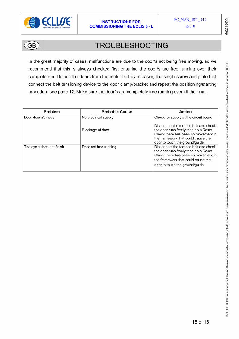
TROUBLESHOOTING
In the great majority of cases, malfunctions are due to the door/s not being free moving, so we
recommend that this is always checked first ensuring the door/s are free running over their
complete run. Detach the doors from the motor belt by releasing the single screw and plate that
connect the belt tensioning device to the door clamp/bracket and repeat the positioning/starting
procedure see page 12. Make sure the door/s are completely free running over all their run.
Problem Probable Cause Action Door doesn’t move No electrical supply
Blockage of door
Check for supply at the circuit board Disconnect the toothed belt and check the door runs freely then do a Reset Check there has been no movement in the framework that could cause the door to touch the ground/guide
The cycle does not finish Door not free running Disconnect the toothed belt and check the door runs freely then do a Reset Check there has been no movement in the framework that could cause the door to touch the ground/guide
GB
05/2
010
©E
CLI
SS
E,al
lrig
hts
rese
rved
.The
use,
filin
gan
dto
talo
rpar
tialr
epro
duct
ion
ofte
xts,
draw
ings
and
pict
ures
cont
aine
din
this
publ
icat
ion
usin
gan
ym
echa
nica
lore
lect
roni
cm
eans
isst
rictly
forb
idde
nun
less
spec
ifica
llyap
prov
edin
writ
ing
byE
CLI
SSE
.60
3010
400