Gaywood Estate Feasibility Report
24
Webb Yates Engineers Ltd 48-50 Scrutton Street London. EC2A 4HH 020 3696 1550 [email protected] www.webbyates.com Registered in England & Wales No.: 5393930 Gaywood Estate Feasibility Report J4409 Southwark Rooftop Housing Ref: J4409-S-RP-0003 Revision: 01 Status: S9
Transcript of Gaywood Estate Feasibility Report
Webb Yates Engineers Ltd
48-50 Scrutton Street
London. EC2A 4HH 020 3696 1550
www.webbyates.com
Registered in England & Wales No.: 5393930
Gaywood Estate Feasibility Report
J4409 Southwark Rooftop Housing
Ref: J4409-S-RP-0003
Revision: 01
Status: S9
J4409-S-RP-0003
2
CONTENTS
DOCUMENT CONTROL ................................................................................................................................ 3
REVISION HISTORY ....................................................................................................................................... 3
1. EXECUTIVE SUMMARY ................................................................................................................. 4
2. INTRODUCTION ............................................................................................................................ 5
2.1. Site Location ............................................................................................................................................................................... 5
2.2. Ground Conditions ................................................................................................................................................................... 5
3. EXISTING BUILDINGS ................................................................................................................... 6
3.1. Structural Form ......................................................................................................................................................................... 9
3.3. Historic Design Guidance .....................................................................................................................................................12
3.4. Condition ..................................................................................................................................................................................12
4. STRUCTURAL PROPOSALS........................................................................................................ 13
4.1. Option 1 ....................................................................................................................................................................................13
4.2. Option 2 ....................................................................................................................................................................................13
4.3. Limitations .................................................................................................................................................................................14
4.4. Embodied Carbon ...................................................................................................................................................................14
4.5. Wind Loading ...........................................................................................................................................................................14
4.6. Disproportionate Collapse ...................................................................................................................................................14
5. INVESTIGATION WORKS ........................................................................................................... 16
5.1. Ground investigations ............................................................................................................................................................16
5.2. Concrete Testing.....................................................................................................................................................................16
5.3. Masonry Testing ......................................................................................................................................................................16
APPENDIX A – STRUCTURAL SKETCHES .............................................................................................. 17
APPENDIX B – PRELIMINARY STRUCTURAL CALCULATIONS ......................................................... 22

J4409-S-RP-0003
3
DOCUMENT CONTROL
Document number: J4409-S-RP-0003
Status: S9 Reason for issue: DRAFT for Information
Date: 29/06/21 Revision: 01
Author: Florence Browning
Signature:
Reviewer: Anna Beckett
Signature:
Approver: Andy Yates
Signature
REVISION HISTORY
Date Status Revision
21/01/21 S9 00
29/06/21 S9 01
© Copyright 2021 Webb Yates Engineers Ltd.
This document has been prepared in accordance with the scope of Webb Yates Engineers appointment and is subject to the terms of that appointment. Webb
Yates Engineers accepts no liability or responsibility to any other party in respect of any use or reliance upon this document. Any modification to this
document subsequent to issue by Webb Yates Engineers shall not be considered valid.

J4409-S-RP-0003
4
1. EXECUTIVE SUMMARY
This report outlines various structural feasibility options for adding an additional storey to an existing residential block, located
on Gaywood Estate in Southwark, to provide new housing units. The existing building considered in this report is Newman
House, comprising of 4 storeys. The building contains a total of 163 units and is thought to have been built between the late
1960s and early 70s.
A visual survey of the building was completed in December 2020, with a subsequent visit to a vacant third floor unit in January
2021. The following report outlines the findings of this visits, potential options and the survey works required to proceed with
the design, to extend the building by 1 storey. Based on the assumptions outlined in this report, to the age and form of the
building, it is believed that there is a reasonable amount of available load capacity and that there is some scope to add an
additional lightweight storey on top with little or no structural interventions required to the existing structure.
The options discussed propose using various forms of lightweight construction with limited strengthening works to the existing
structure and foundations. This makes the best use of the existing building, minimises the impact on the surrounding buildings
and provides a solution with a relatively low carbon footprint.
Due to the age of the existing building, the structure will not have been designed to the current regulations for robustness and
disproportionate collapse. The extension to the existing 4 storey block will also result in an increase in Consequence Class of
the building. It is likely that adequate measures are already present in the existing design, however further investigation is
required to confirm and justify these details. It is probable that additional measures may be required for the structure to
conform to the current regulations.
In order to progress further with the design, investigation works as detailed in this report are required to determine the
foundations, structural build up and material strength of the building. With this information the structural scheme can be
developed in more detail alongside the architectural design.
J4409-S-RP-0003
5
2. INTRODUCTION
As part of proposals to provide new housing within the London Borough of Southwark, Webb Yates have been appointed to
provide a feasibility study for adding an additional storey to Newman House, an existing residential block on Gaywood Estate.
This report describes the existing building and outlines the potential options for constructing an additional storey, as well as the
testing and investigation works that would be required in order to complete the design.
2.1. Site Location
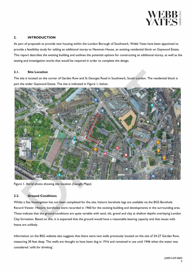
The site is located on the corner of Garden Row and St Georges Road in Southwark, South London. The residential block is
part the wider Gaywood Estate. The site is indicated in Figure 1, below.
Figure 1. Aerial photo showing site location (Google Maps)
2.2. Ground Conditions
Whilst a Site Investigation has not been completed for the site, historic borehole logs are available via the BGS Borehole
Record Viewer. Historic boreholes were recorded in 1960 for the existing building and developments in the surrounding area.
These indicate that the ground conditions are quite variable with sand, silt, gravel and clay at shallow depths overlaying London
Clay formation. Based on this, it is expected that the ground would have a reasonable bearing capacity and that issues with
heave are unlikely.
Information on the BSG website also suggests that there were two wells previously located on the site of 24-27 Garden Row,
measuring 30 feet deep. The wells are thought to have been dug in 1916 and remained in use until 1946 when the water was
considered ‘unfit for drinking’.
J4409-S-RP-0003
6
3. EXISTING BUILDINGS
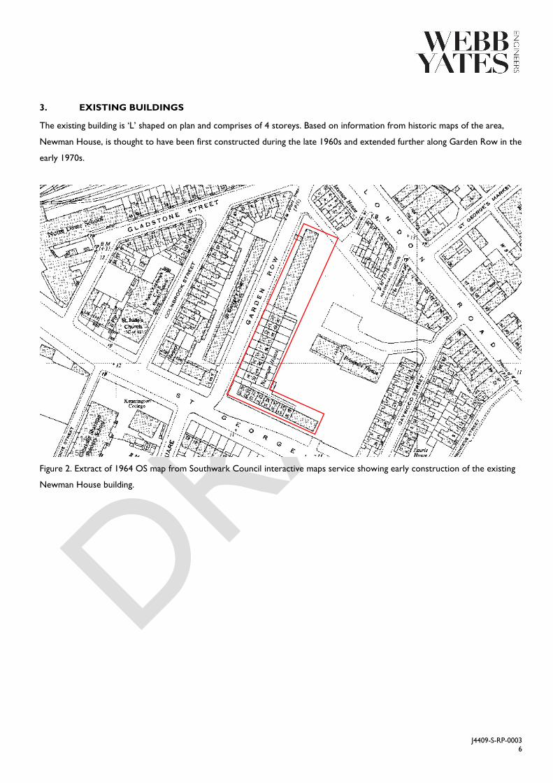
The existing building is ‘L’ shaped on plan and comprises of 4 storeys. Based on information from historic maps of the area,
Newman House, is thought to have been first constructed during the late 1960s and extended further along Garden Row in the
early 1970s.
Figure 2. Extract of 1964 OS map from Southwark Council interactive maps service showing early construction of the existing
Newman House building.
J4409-S-RP-0003
7
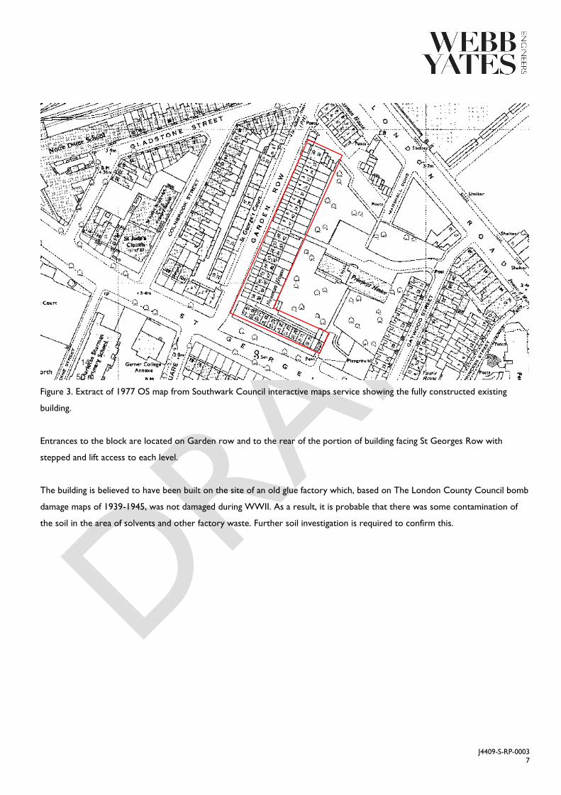
Figure 3. Extract of 1977 OS map from Southwark Council interactive maps service showing the fully constructed existing
building.
Entrances to the block are located on Garden row and to the rear of the portion of building facing St Georges Row with
stepped and lift access to each level.
The building is believed to have been built on the site of an old glue factory which, based on The London County Council bomb
damage maps of 1939-1945, was not damaged during WWII. As a result, it is probable that there was some contamination of
the soil in the area of solvents and other factory waste. Further soil investigation is required to confirm this.
J4409-S-RP-0003
8
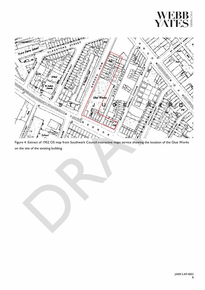
Figure 4. Extract of 1952 OS map from Southwark Council interactive maps service showing the location of the Glue Works
on the site of the existing building.
J4409-S-RP-0003
9
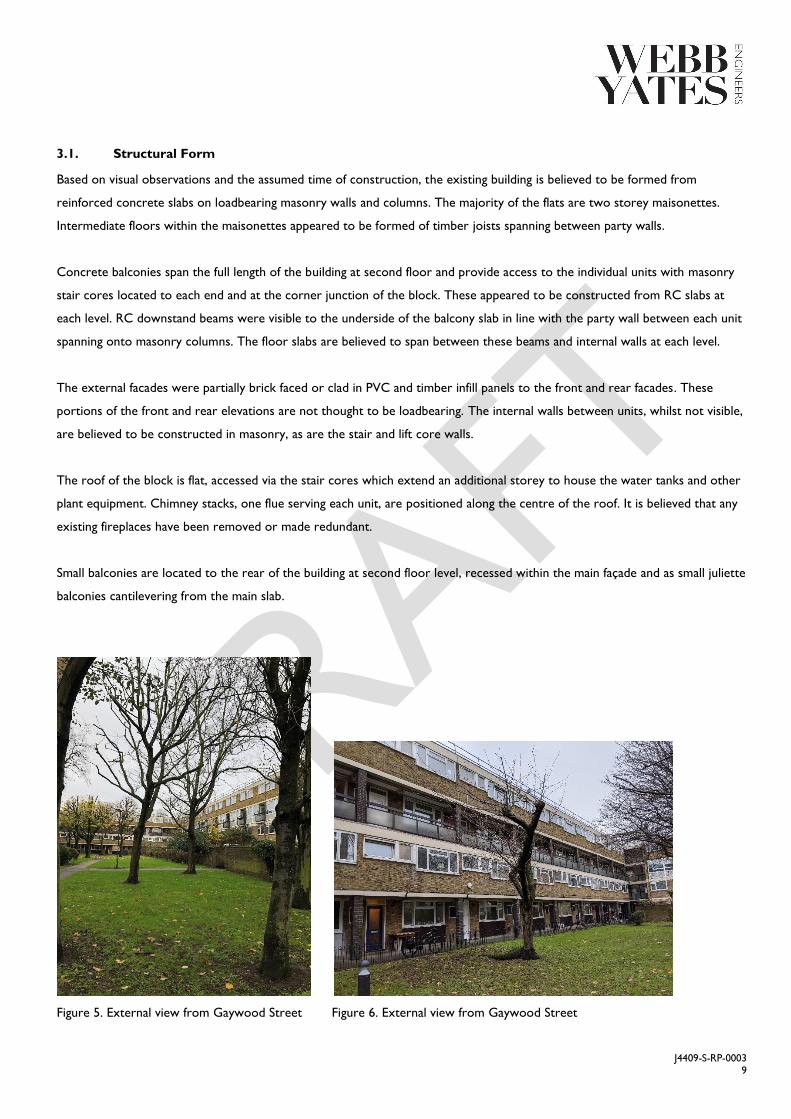
3.1. Structural Form
Based on visual observations and the assumed time of construction, the existing building is believed to be formed from
reinforced concrete slabs on loadbearing masonry walls and columns. The majority of the flats are two storey maisonettes.
Intermediate floors within the maisonettes appeared to be formed of timber joists spanning between party walls.
Concrete balconies span the full length of the building at second floor and provide access to the individual units with masonry
stair cores located to each end and at the corner junction of the block. These appeared to be constructed from RC slabs at
each level. RC downstand beams were visible to the underside of the balcony slab in line with the party wall between each unit
spanning onto masonry columns. The floor slabs are believed to span between these beams and internal walls at each level.
The external facades were partially brick faced or clad in PVC and timber infill panels to the front and rear facades. These
portions of the front and rear elevations are not thought to be loadbearing. The internal walls between units, whilst not visible,
are believed to be constructed in masonry, as are the stair and lift core walls.
The roof of the block is flat, accessed via the stair cores which extend an additional storey to house the water tanks and other
plant equipment. Chimney stacks, one flue serving each unit, are positioned along the centre of the roof. It is believed that any
existing fireplaces have been removed or made redundant.
Small balconies are located to the rear of the building at second floor level, recessed within the main façade and as small juliette
balconies cantilevering from the main slab.
Figure 5. External view from Gaywood Street Figure 6. External view from Gaywood Street

J4409-S-RP-0003
10
Figure 7. External view of stair core Figure 8. Internal view of stair core
Figure 9. External view 2nd floor walkway Figure 10. External view of Newman House

J4409-S-RP-0003
11
Figure 11. External view of rear balconies Figure 12. Internal view of timber floor
Figure 13. External view of roof Figure 14. External view of roof
J4409-S-RP-0003
12
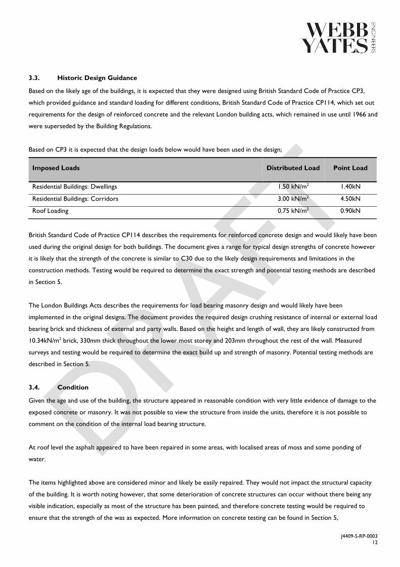
3.3. Historic Design Guidance
Based on the likely age of the buildings, it is expected that they were designed using British Standard Code of Practice CP3,
which provided guidance and standard loading for different conditions, British Standard Code of Practice CP114, which set out
requirements for the design of reinforced concrete and the relevant London building acts, which remained in use until 1966 and
were superseded by the Building Regulations.
Based on CP3 it is expected that the design loads below would have been used in the design;
Imposed Loads Distributed Load Point Load
Residential Buildings: Dwellings 1.50 kN/m2 1.40kN
Residential Buildings: Corridors 3.00 kN/m2 4.50kN
Roof Loading 0.75 kN/m2 0.90kN
British Standard Code of Practice CP114 describes the requirements for reinforced concrete design and would likely have been
used during the original design for both buildings. The document gives a range for typical design strengths of concrete however
it is likely that the strength of the concrete is similar to C30 due to the likely design requirements and limitations in the
construction methods. Testing would be required to determine the exact strength and potential testing methods are described
in Section 5.
The London Buildings Acts describes the requirements for load bearing masonry design and would likely have been
implemented in the original designs. The document provides the required design crushing resistance of internal or external load
bearing brick and thickness of external and party walls. Based on the height and length of wall, they are likely constructed from
10.34kN/m2 brick, 330mm thick throughout the lower most storey and 203mm throughout the rest of the wall. Measured
surveys and testing would be required to determine the exact build up and strength of masonry. Potential testing methods are
described in Section 5.
3.4. Condition
Given the age and use of the building, the structure appeared in reasonable condition with very little evidence of damage to the
exposed concrete or masonry. It was not possible to view the structure from inside the units, therefore it is not possible to
comment on the condition of the internal load bearing structure.
At roof level the asphalt appeared to have been repaired in some areas, with localised areas of moss and some ponding of
water.
The items highlighted above are considered minor and likely be easily repaired. They would not impact the structural capacity
of the building. It is worth noting however, that some deterioration of concrete structures can occur without there being any
visible indication, especially as most of the structure has been painted, and therefore concrete testing would be required to
ensure that the strength of the was as expected. More information on concrete testing can be found in Section 5,

J4409-S-RP-0003
13
4. STRUCTURAL PROPOSALS
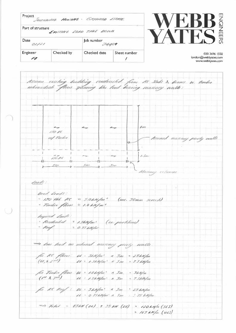
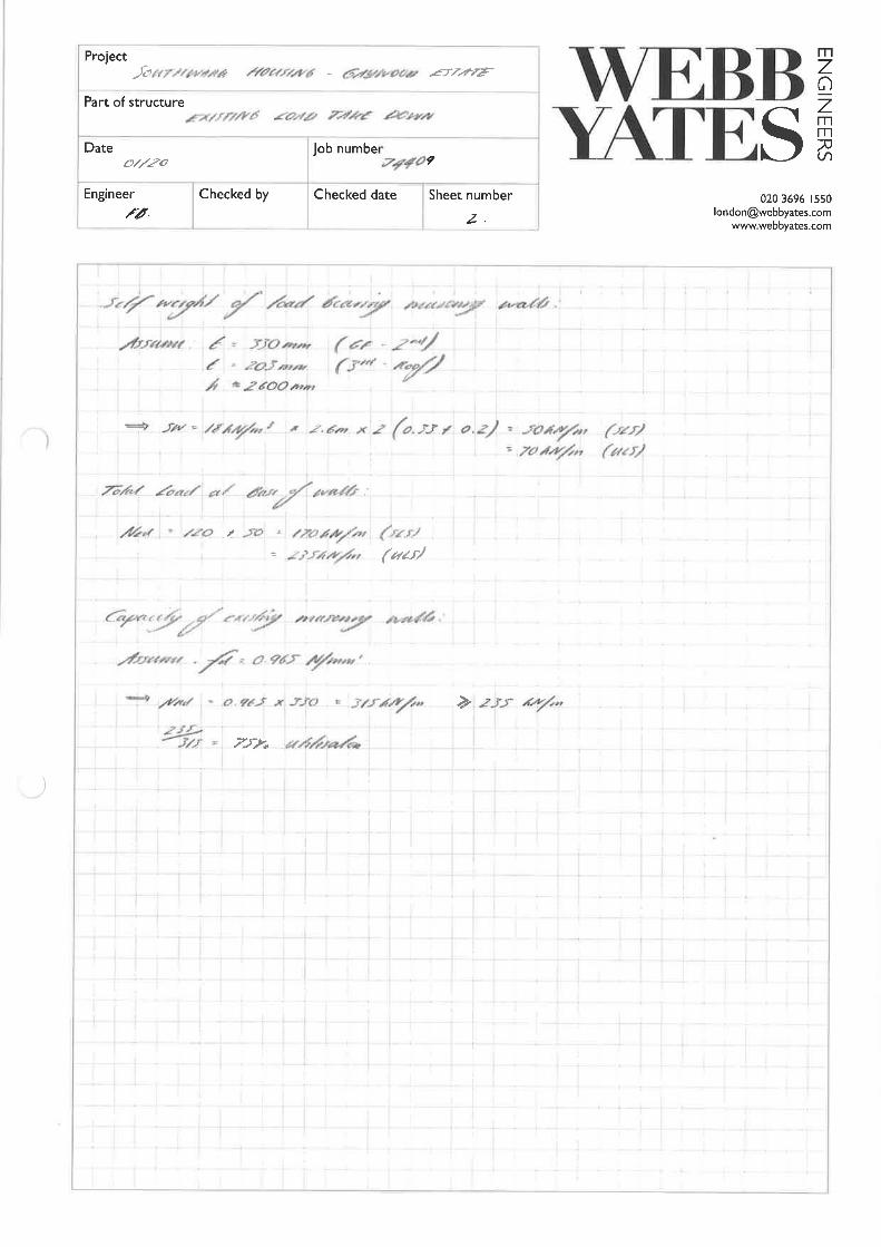
Based on the assumed age and form of the building, an outline load take down has been completed to assess the current loads
onto the structure and basic calculations have been carried out to determine the likely capacity of the load bearing masonry
walls. From assumptions made to the structural build up and material strength, in accordance with the relevant codes and
standards of the time, the masonry walls were found to be working at around 75% of their current capacity. This suggests that
there is scope to add an additional floor to these buildings with little or no structural interventions required to the existing
structure.
The assumptions made on the structural build up of the RC floors and strength of masonry walls are relatively conservative, as
it was not possible to ascertain these properties from visual inspection. Further investigations, as outlined in Section 5, would
allow a more accurate assessment of the existing design loads and capacity of the structure to be undertaken. Verification of
the existing foundations would also be required to establish if they have further capacity to carry additional load.
Based on the calculations we have carried out, the existing masonry walls of the existing building have a reasonable amount of
spare capacity which could be utilised in order to support an additional storey. As a result, two options have been proposed
below. Option 1 is for steel frame with composite slabs, whereas Option 2 is for a timber frame. These options are discussed
in more detail below. Both options are relatively lightweight structures and considered appropriate forms of construction to
form an additional storey without significant alterations to the existing structure being required.
4.1. Option 1
A steel frame solution with composite deck is considered suitable to construct the additional storey to the existing buildings.
The composite deck would be raised over the existing roof level to form a new floor, supported on new steel beams spanning
between units below. The new roof would also be constructed following a similar form. Loadbearing elements would be
located above the existing masonry walls, avoiding additional loads onto the existing roof slab, and minimising strengthening
works. Modifications to the existing structure may be required in order to provide access to the upper floors and some
localised strengthening may be required. Sketches showing possible framing layouts are included in Appendix A.
4.2. Option 2
Timber is also considered suitable method of construction to form the additional storey to the existing buildings, either using
timber framing or CLT. The timber deck would be raised over the existing roof level to form a new floor, supported on new
engineered timber beams spanning between units. The new roof would also be constructed following a similar form with
external timber stud or CLT walls. As for Option 1, loadbearing elements would be located above the existing masonry walls,
avoiding additional loads onto the existing roof slab, and minimising strengthening works. It is worth noting that the use of
timber may not comply with the requirements of the Southwark New Homes Design Standard and this would need to be
confirmed at the start of any design stage. Sketches showing possible framing layouts are included in Appendix A.
J4409-S-RP-0003
14
4.3. Limitations
The existing roof level is currently accessed via a roof hatches located above the stair cores. Therefore, modifications to the
existing structure may be required in order to provide access to the new storey and some localised strengthening may be
required.
Whilst the load bearing masonry walls do appear to have additional capacity based on the assumptions made, it is not possible
to determine the size or form of the foundations and therefore the capacity of the existing foundations is currently unknown.
Typically it is acceptable to increase the loads onto foundations by around 10% without requiring additional investigation,
however the additional loads proposed above would be significantly higher than this and therefore further investigation would
be required. Investigation works have been outlined in more detail in Section 5.
4.4. Embodied Carbon
As climate change becomes an ever more important issue then the impact of any works on the environment needs to be
considered. Retaining the existing building and extending it offers significant advantages over demolition in terms of embodied
carbon, particularly if new interventions can be constructed in timber and the need for new foundations can be avoided. As a
result, Option 2, a timber structure, would be the preferable option from an environmental perspective.
4.5. Wind Loading
The proposed additional storey height will result in an increase in wind loading on the block, proportional to the increase in
building height. It is believed that the existing stability system, assumed to be comprised of masonry shear walls, is able to
accommodate this percentage increase in lateral wind load. The new rooftop extension will be adequately tied to the existing
structures, allowing the additional lateral forces to be transferred to the existing stability system and foundations.
4.6. Disproportionate Collapse
Due to the age of the existing building, the structure will not have been designed to conform with the current requirements for
robustness and disproportionate collapse. The 4 storey residential block is currently considered as Consequence Class 2A
buildings. In accordance with Approved Document A and BS EN 1991-1-7, robustness is to be achieved via the provision of
effective horizontal ties or effective anchorage of suspended floors and roofs to walls. Based on the assumed form of
construction, it is likely that adequate provision of effective horizontal ties is already achieved using standard construction
details such the reinforcement in the existing RC slabs. Further investigation is required to confirm these details and whether
any additional means of tying are required for the structures to conform to current regulations.
J4409-S-RP-0003
15
The extension to the existing 4 storey block however, will result in an increase in Consequence Class of the buildings to Class
2B meaning, in addition to effective horizontal ties as discussed above, effective vertical ties must also be provided to ensure
sufficient robustness is achieved. Where vertical ties cannot be appropriately detailed, such as in masonry construction,
notional column/wall removal may be applied to demonstrate that the removal of individual loadbearing element does not cause
collapse of more than 15% of the plan area at that level. It is likely that this approach is feasible with the assumptions made to
the existing structure however, further calculations will be required at the next stage to justify that, under the accidental load
case, the existing concrete slabs are able to span in the transverse direction, or that the masonry wall is able to cantilever as a
deep beam over the notional opening.
It will be necessary to set out the proposed strategy for disproportionate collapse in the initial design stage and confirm this
with the approved inspector. The likely approach is outlined below.
4.6.1. Newman House
The proposal to add an additional storey of lightweight modular construction on top of the existing 4 storey Newman House
building, will result in an increase in Consequence Class of the buildings from Class 2A to Class 2B. As described above, in
order to ensure the requirements of effective horizontal ties is satisfied, further intrusive investigation to the existing structure
is required to confirm that suitable provision is inherent in the design. Where the existing details do not provide adequate
means, additional horizontal ties will be required between the existing floors and walls.
Due to the form of construction of the existing building, it is unlikely that new vertical ties can be appropriately detailed
without significant structural intervention. Therefore, the method of notional wall removal may be applied to demonstrate that
the local removal of a loadbearing wall does not cause collapse of more than 15% of the plan area at that level and that the
existing concrete slabs are able to span in the transverse direction with the masonry cantilevering as a deep beam over the
notional opening.
J4409-S-RP-0003
16
5. INVESTIGATION WORKS
5.1. Ground investigations
Whilst some assumptions can be made about the foundations based on the ground conditions and the age of the building, it is
very difficult to determine the exact form of the foundations without investigation. If the load onto the foundations was
expected to increase significantly then investigation works would be required to ensure that the existing foundations were
sufficient and to determine the form of any new foundations, if required.
It is expected that these investigations would involve digging trial pits to expose the foundations in a number of locations, as
well as a laboratory testing to determine the properties of the soil. If new foundations were expected, then tests can also be
carried out to determine if there are any existing contaminants in the surrounding ground.
5.2. Concrete Testing
In order to determine the condition and strength of the existing concrete structure, concrete testing would be required. In
particular, due to the age of the building, carbonation of the concrete is a particular concern. Carbonation is the reaction of
carbon dioxide in the environment with the calcium hydroxide in the cement paste and this can lead to more rapid corrosion
of the reinforcement. If required, we can provide a scope of works and obtain quotes for the testing.
5.2.1. Reinforcement
In order to ascertain the reinforcement in the structural members a cover meter survey would be proposed, with
reinforcement broken out and exposed in some locations to substantiate the survey. It is likely we would also test a sample of
the reinforcement to determine the strength. Whilst there was no evidence of corrosion to the reinforcement in the members
that we viewed half-cell testing could be used to determine if there is any corrosion and the extent of this.
5.2.2. Concrete
A survey of the beams and slabs to record all damage and cracking would be undertaken and if cracking is identified then
further investigation may be required to determine the depth of the cracks. Samples of the concrete should also be testing to
determine the strength. Due to the age of the structure then carbonation may be an issue and therefore carbonation testing
and a chloride profile examination would be recommended. It is also suggested that a test is completed to ascertain whether
Alkali-Silica Reactions (ASR) may be causing detrimental effects to the concrete structure.
5.3. Masonry Testing
In order to determine the strength of the existing masonry structure, masonry testing would be required. It is likely we would
take a number of samples of whole bricks and mortar from various locations. An approximate basic compressive stress for the
brickwork and mortar can then be estimated. We would suggest these bricks are taken from an area where they would not be
visible or would be removed during the works for example, the stair overrun. If required, we can provide a scope of works and
obtain quotes for the testing.

J4409-S-RP-0003
17
APPENDIX A – STRUCTURAL SKETCHES
Drawing Title
Project
Date Drawn by Scale
Drawing No
Revision [email protected]
www.webbyates.co.uk020 3696 1550
StatusSouthwark Housing
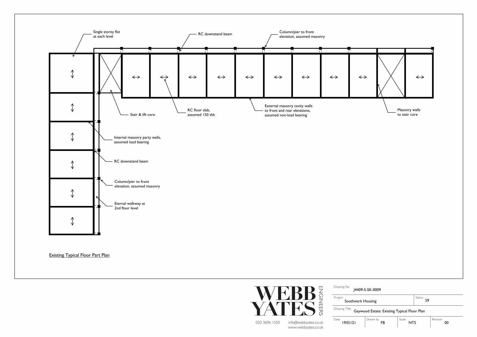
Gaywood Estate: Existing Typical Floor Plan
19/01/21 FB
J4409-S-SK-0009
00NTS
S9
RC floor slab,assumed 150 thk
External masonry cavity wallsto front and rear elevations,assumed non-load bearing
Internal masonry party walls,assumed load bearing
Masonry wallsto stair core
RC downstand beam
Column/pier to frontelevation, assumed masonry
Eternal walkway at2nd floor level
Single storey flatat each level
Stair & lift core
Existing Typical Floor Part Plan
RC downstand beam Column/pier to frontelevation, assumed masonry
Drawing Title
Project
Date Drawn by Scale
Drawing No
Revision [email protected]
www.webbyates.co.uk020 3696 1550
StatusSouthwark Housing
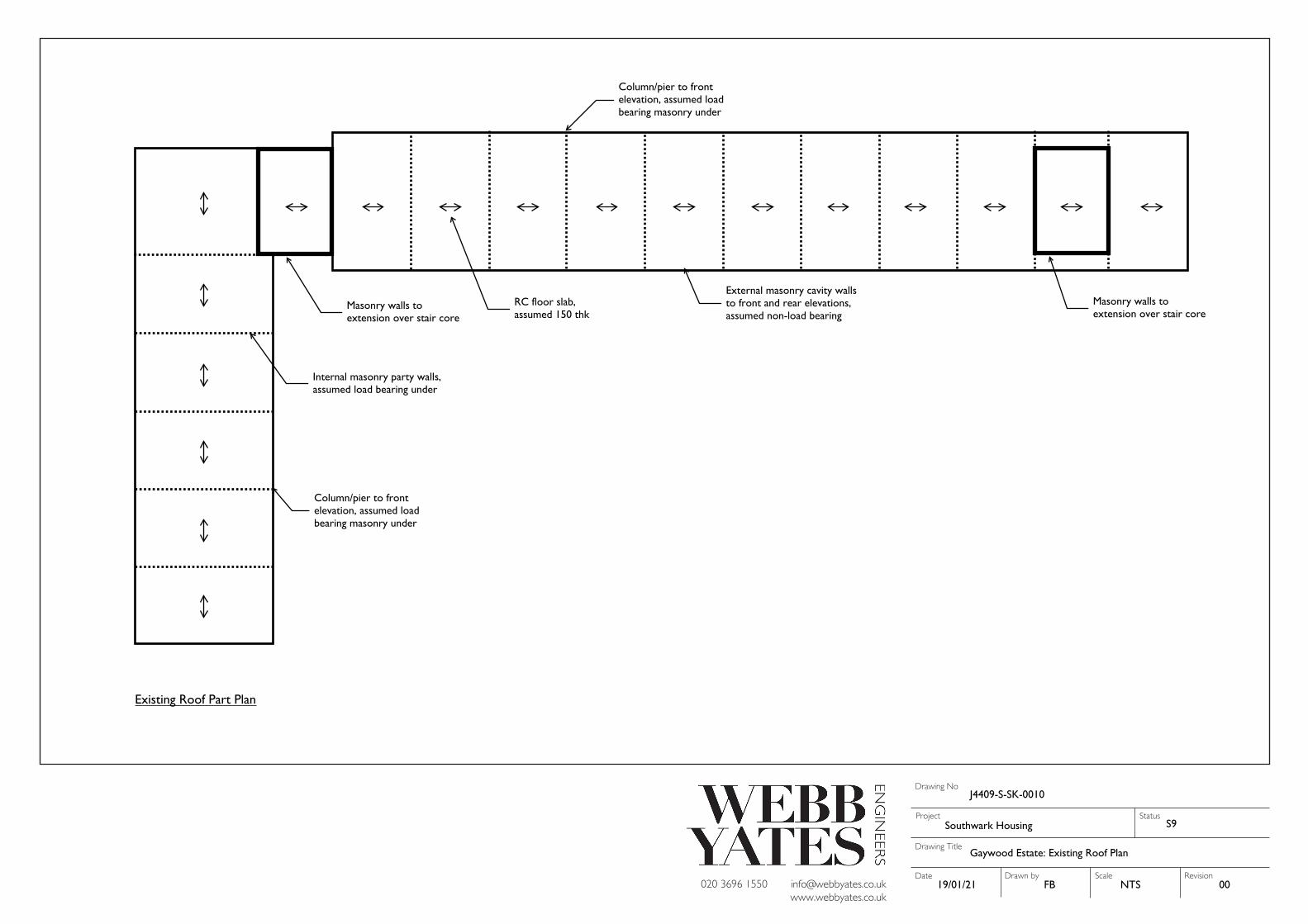
Gaywood Estate: Existing Roof Plan
19/01/21 FB
J4409-S-SK-0010
00NTS
S9
RC floor slab,assumed 150 thk
External masonry cavity wallsto front and rear elevations,assumed non-load bearing
Internal masonry party walls,assumed load bearing under
Masonry walls toextension over stair core
Column/pier to frontelevation, assumed loadbearing masonry under
Masonry walls toextension over stair core
Existing Roof Part Plan
Column/pier to frontelevation, assumed loadbearing masonry under

Drawing Title
Project
Date Drawn by Scale
Drawing No
Revision [email protected]
www.webbyates.co.uk020 3696 1550
StatusSouthwark Housing
Gaywood Estate: Proposed Roof Extension - Option 1
19/01/21 FB
J4409-S-SK-0011
00NTS
S9
Proposed Roof Extension - Option 1
Existing internal masonryparty walls, assumed loadbearing under
New composite deckover existing roof
New steel columns tosupport new lightweightcomposite roof
Existing masonry walls tostair and lift core,modified to suit proposedlayout
Existing external masonrycavity walls to front and rearelevations, assumed non-loadbearing
Existing RC roof slab,assumed 150 thk
New steel beamssupported on existingload bearing walls under
New steel columns tosupport new lightweightcomposite floor and roof
New composite deckover existing roof toform additional stories
New steel beamssupported on existingload bearing walls under
Existing internal masonryparty walls, assumed loadbearing under
Existing external masonrycavity walls to front and rearelevations, assumed non-loadbearing
Existing masonry walls tostair and lift core,modified to suit proposedlayout
Existing RC roof slab,assumed 150 thk
Drawing Title
Project
Date Drawn by Scale
Drawing No
Revision [email protected]
www.webbyates.co.uk020 3696 1550
StatusSouthwark Housing
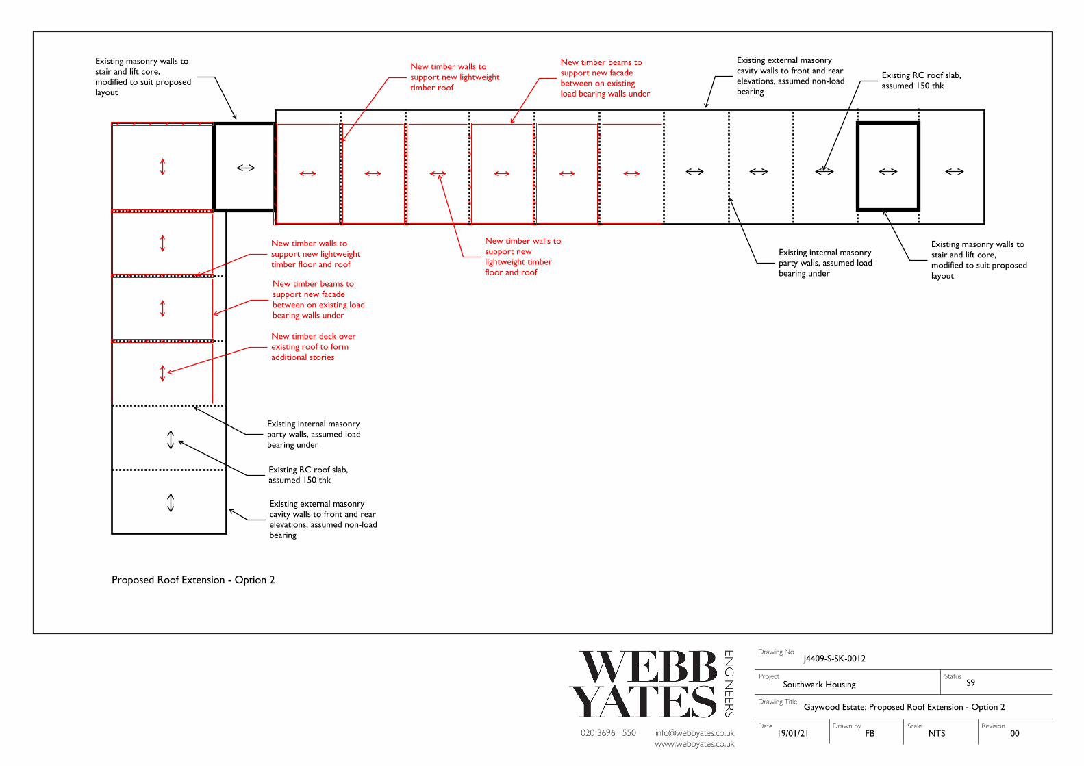
Gaywood Estate: Proposed Roof Extension - Option 2
19/01/21 FB
J4409-S-SK-0012
00NTS
S9
Proposed Roof Extension - Option 2
Existing internal masonryparty walls, assumed loadbearing under
New timber walls tosupport newlightweight timberfloor and roof
New timber walls tosupport new lightweighttimber roof
Existing masonry walls tostair and lift core,modified to suit proposedlayout
Existing external masonrycavity walls to front and rearelevations, assumed non-loadbearing
Existing RC roof slab,assumed 150 thk
New timber beams tosupport new facadebetween on existingload bearing walls under
New timber beams tosupport new facadebetween on existing loadbearing walls under
New timber deck overexisting roof to formadditional stories
New timber walls tosupport new lightweighttimber floor and roof
Existing internal masonryparty walls, assumed loadbearing under
Existing external masonrycavity walls to front and rearelevations, assumed non-loadbearing
Existing masonry walls tostair and lift core,modified to suit proposedlayout
Existing RC roof slab,assumed 150 thk
J4409-S-RP-0003
22
APPENDIX B – PRELIMINARY STRUCTURAL CALCULATIONS