Gaylord® Harmony™ Shelving Assembly Instructions
10
Assembly Instruons r42", 48", 60", 72" and 84'' Single 1 Fa and Double FaceSheMng Un scrions S"mgle face Sta U: End Panel f2) ha,s two holes with threaded insert at top and boom of the inside of the panel-the inside back edse of each panel ils grooved ac:c. ept a , back if order-the boom each pane is indi�ed by .2 single shelfsuppo ho es above the threaded insen Base Unit ti) is aached with bolts between end nel at boom side just below the 2 s·ngle she f s.uppo. holes,. The grood back rail l on the base unit wm line up wiith the back groove on the end panel. To,p Fi i ller Unit u .. ) 42", 48" and 60 1 " top units have laminated or eneer suces with groove 0+ the unde"de to aooept back if ordered. On 72" & 84" top units the finished veneer side is down th a grooe on the finished s·de to accept a back if oered. th top filler uni , ts are aached beeen the tops of , end pae� with bolts. supplied See ig #1 Sheling-Sol l id shelving grooved on underside to rest on round 1" half thread shelf suppon:. For , 72" & T" tall units (1) shelf is not grooved. Th"s sheff ·s to be inslled • t a 1 pp:ro:ximatelv he center of the unit he"ght using the ,(4) sפc:al flat end shelf sup;pos prded� (s. she must be installed ·nsure the stamlity of' the unit. See 1g. #1 for the correct number of shelves per unit size-this number includes the boom shelf, which r , est on the base unit, and the ungrooved shel for the 6, 72" & T" ll units. Badc. 1 Panel• the ba paneI I ii s ordered as an opon and s finished one sid , e only. If no back is ord , e·red a set of an•s,way bl , es are prod. s = ngle 1 F£e Adder Un End Panel (1)- h , as two th1ugh holes at top and boom . of panel. The back ege of the panel ·s grooyed on , each side to accept a back panel l if ordered. e boom of the end panel is id , enfied by the o s·ngte shelf suppo holes which are locat above the boom two through holes. Ba,se Unit U.)· the adder base is the same as the staer base o,p Filer Unit U)· . same as the staer unit SheMng- same as the staer uit Badc. 1 Pnel· . same as the staer unit ** Adder uns must be conneed a starter unit
Transcript of Gaylord® Harmony™ Shelving Assembly Instructions
Assembly Instructions for42", 48", 60", 72" and 84'' Single 1Face and Double FaceSheMng
Unit Descriptjons
S"mgle face Starter Uniit:
End Panell f2) ha,s two holes with threaded insert at top and bottom of the inside of the panel-the inside back edse of each
panel ils grooved to ac:c.ept a, back if order-the bottom of each pane is indic:a�ed by .2 single shelfsupport ho es above the
threaded insen
Base Unit ti) is attached with bolts between end panells at bottom side just below the 2 s·ngle she f s.upport. holes,. The
grooved back raill on the base unit wm line up wiith the back groove on the end panel.
To,p Fiiller Unit u .. ) 42", 48" and 601" top units have laminated or \lleneer surfaces with groove 011 the unders"de to aooept back if
ordered. On 72" & 84" top units the finished veneer side is down with a groo\lle on the finished s·de to accept a back if
on:lered. Both top filler uni,ts are attached between the tops of ,end pan,e� with bolts. supplied. .. See !Fig .. #1
Shel"'ing-Sollid shelving grooved on underside to rest on round 1" half thread shelf suppon:. For 60", 72" & 84" tall units (1)
shelf is not grooved. Th"s sheff ·s to be installed • t a1pp:ro:ximatelv t!he center of the unit he"ght using the ,(4) spec::"al flat
end shelf sup;ports provided� Tt(s. shelf must be installed to ·nsure the stamlity of' the unit. See IF1g ... #1 for the correct
number of shelves per unit size-this number includes the bottom shelf, which r,est on the base unit, and the ungrooved
shelif for the 60", 72" & 84" tall units.
Badc. 1Panel• the baiek pane II iis ordered as an option and i,s finished one sid,e only. If no back is ord,e·red a set of anti•s,way cabl,es
are provided.
s=ngle 1F.a£e Adder Unit
End Panell (1)- h,as two thrrc1ugh holes at top and bottom .of panel. The back ectge of the panel ·s grooyed on ,each side to
accept a back panell if ordered. The bottom of the end panel is id,entified by the two s·ngte shelf support holes which are
located above the bottom two th rough holes.
Ba,se Unit U.)· the adder base is the same as the starter base
i-:o,p Fiiller Unit U)· .same as the starter unit
SheMng- same as the starter uinit
Badc. 1P.anel· .same as the starter unit
** Adder units must be connected to a starter unit
Double Face Starter Unit
End Panel (2) -Panel edge is faced front & back edge. A groove to accept a back, if ordered, runs top to bottom at the center
of end panel. Two sets of holes with threaded inserts are located at the top and the bottom of each side of the back
groove. Bottom of end panel has two sets of single shelf support holes above threaded insert holes.
Base Unit (1)- 2 finished front rail with grooved center rail for slide in back if ordered.
Top Filler Unit {1)- One unit, which is faced on two sides. The 42", 48" & 60" tall units have a laminated or wood veneer top
surface. The underside is grooved to accept a center partition. For 72" & 84" top fillers the finished veneer side is down
with groove at the middle of the finished panel to accept a center partition if ordered. The top is secured the same as
single face but using 4 bolts per end panel instead of two.
Shelving- Same as the number shown in Fig. #1 x 2 for each size. All specifications are the same as Single Face units but the
number per unit is doubled.
Back Panel- The center partition for double faced units if ordered is finished both sides.
Double Face Adder Unit
End Panel (1)-Panel edge is faced front & back. A back groove to accept a center partition if ordered runs top to bottom at
the center on each face side of the end panel. Two sets of through holes are located at the top and bottom of the panel
on either side of the back groove. The bottom end of the panel has two sets of single shelf support holes above the
through bolt holes.
Base Unit (1) -Same as Double Face Starter unit.
Top Filler Unit (1)-Top filler unit is one piece which is faced on two sides, 42", 48" & 60" tall units have laminated top
surface. The underside is grooved to accept a partition if ordered. For 72• & 84" top filler the finished veneer side is down
with a groove at the middle to accept a center partition if ordered. The top is mounted same as a single face unit but
using 4 bolts per panel instead of two.
Shelving -Same as the number shown on Component page for Double Faced unit.
Back Panel -The center partition for double-faced units, if ordered, are finished on both sides.
BEFORE BEGINNING ASSEMBLY, PLEASE REVIEW COMPONENTS SHEET AND HARDWARE SHEET.
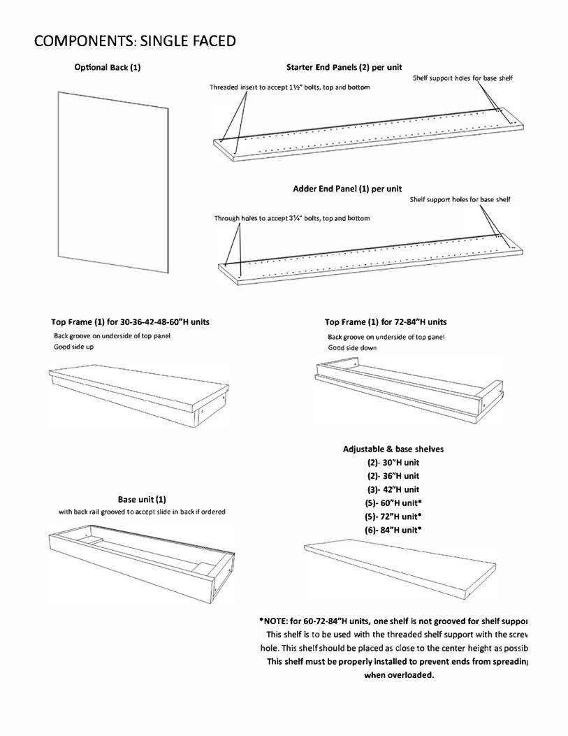
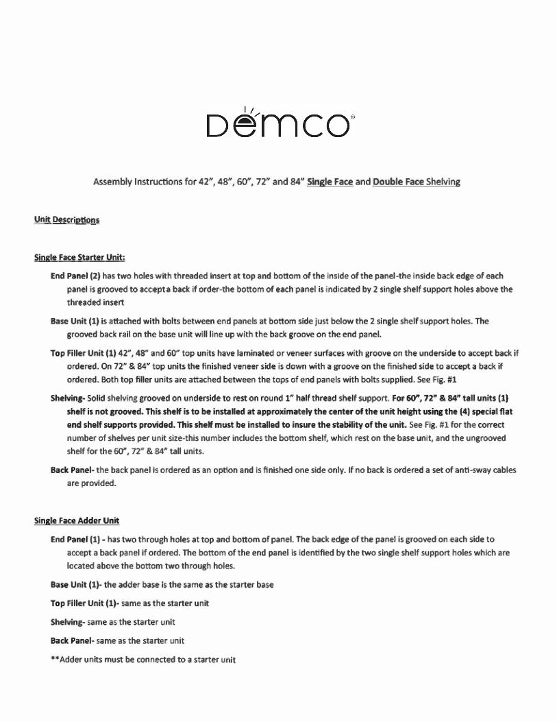
COMPONENTS: SINGLE FACED
Optional Back (11 Starter End Panels (21 per unit Shetf support holes f r base shelf
Threaded insert to accept 1 ½"'
bolts, top and bottom
.. . .
Adder End Panel (11 per unit Shelf support holes for base shetf
Through holes to accept 3¼" bolts, top and bottom
Top Frame (11 for 30-36-42-48-GO"H units
Back groove on underside of top panel
Good side up
Base unit (11
with back rall grooved to accept slide in back tf 0<dered
. . . .
. . . .
. . . . . . . . .
. . . . .
. . . .
Top Frame (11 for 72-84"H units
Bade groove on underside of top panel
Good side down
Adjustable & base shelves
(21- 30"H unit
(21- 36"H unit
(31· 42"H unit
(SI· 60"H unit*
(SI· 72"H unit*
(61· 84"H unit*
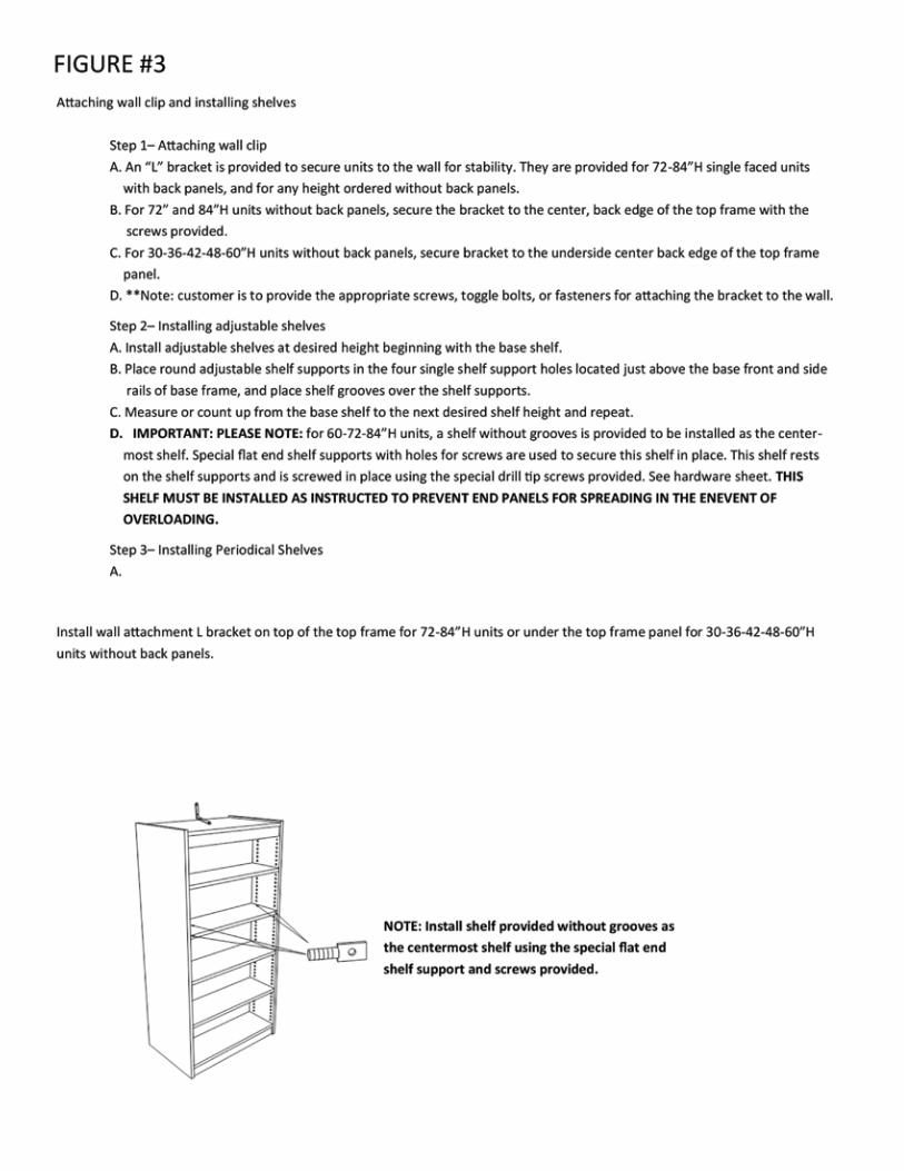
*NOTE: for 60-72-84"H units, one shelf is not grooved for shelf suppo1
This shelf is to be used with the threaded shelf support with the sere,
hole. This shelf should be placed as dose to the center height as possib
This shelf must be properly Installed to prevent ends from spreadln1
when overloaded.
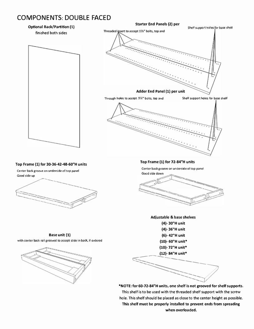
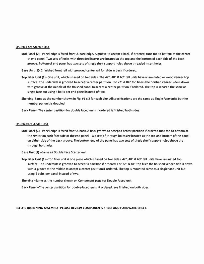
COMPONENTS: DOUBLE FACED Optional Bade/Partition (1)
finished both sides
Starter End Panels (2) per Shelf support holes or base shelf
Adder End Panel (1) per unit
Through holes to accept 3¼'" bolU, top and Shelf support holes for base shelf
Top Frame (1) for 30-36-42-48·60"H units Center back groove on underside of top panel Good side up
�------�--- --.:::::=--
� • ----��l -----:::u.-,..........
Base unit (1) with center back rall grooved to accept sllde In bade. If ordered
Top Frame (1) for 72·84"H units Center bade groove on underside of top panel Good side down
-��
�
Adjustable & base shelves (4)· 30"H unit(4)· 36"H unit(6)· 42"H unit
(10)· 60"H unit•(10)· 72"H unit•(12)· 84"H unit•
���------��✓•NOTE: for 60•72•84"H units, one shelf is not grooved for shelf supports.
This shelf is to be used with the threaded shelf support with the screw
hole. This shelf should be placed as dose to the center height as possible. This shelf must be properly installed to prevent ends from spreading
when overloaded.
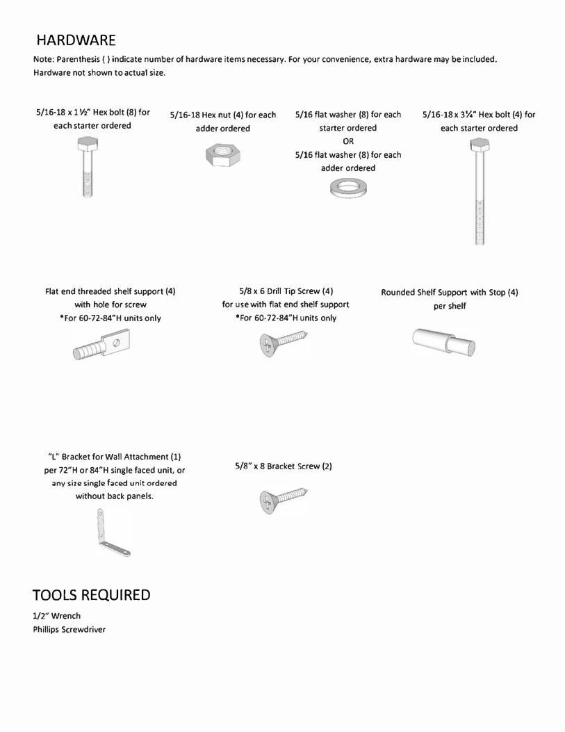
HARDWARE
Note: Parenthesis ( ) indicate number of hardware items necessary. For your convenience, extra hardware may be included.
Hardware not shown to actual size.
5/16-18 x 1 ½" Hex bolt (8) for
each starter ordered 5/16-18 Hex nut (4) for each
adder ordered
5/16 flat washer (8) for each
starter ordered
5/16-18 x 3¼" Hex bolt (4) for
each starter ordered
Flat end threaded shelf support (4)
with hole for screw
*For 60-72-84"H units only
"L" Bracket for Wall Attachment (1)
per 72"H or 84"H single faced unit, or
any size single facEMI unit ordered
without back panels.
TOOLS REQUIRED
1/2"Wrench
Phillips Screwdriver
OR
5/16 flat washer (8) for each
adder ordered
5/8 x 6 Orill Tip Screw (4)
for use with flat end shelf support
•For 60-72-84"H units only
5/8" x 8 Bracket Screw (2)
Rounded Shelf Support with Stop (4)
per shelf
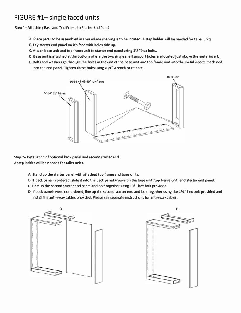
FIGURE #1- single faced units
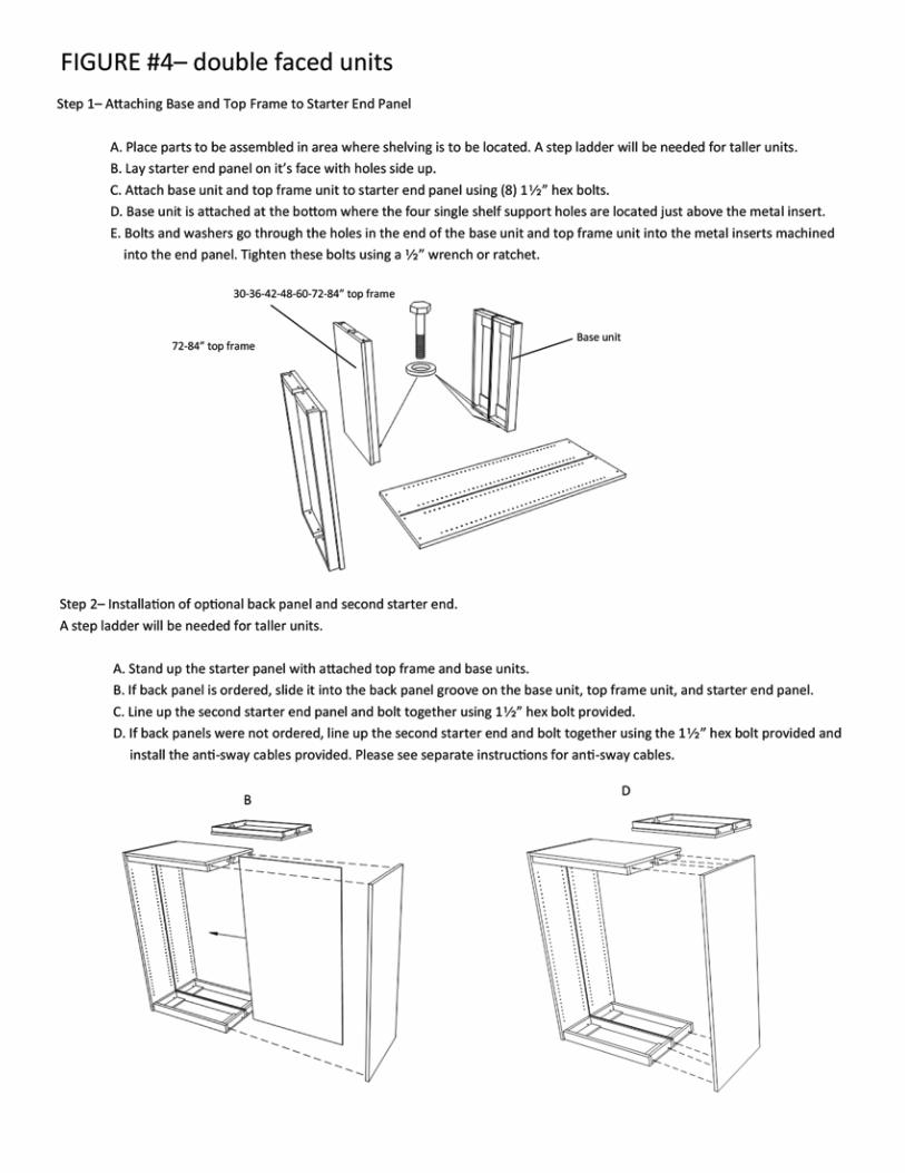
Step 1-Attaching Base and Top Frame to Starter End Panel
A. Place parts to be assembled in area where shelving is to be located. A step ladder will be needed for taller units.
8. Lay starter end panel on it's face with holes side up.
C. Attach base unit and top frame unit to starter end panel using 1 ½" hex bolts.
0. Base unit is attached at the bottom where the two single shelf support holes are located just above the metal insert.
E. Bolts and washers go through the holes in the end of the base unit and top frame unit into the metal inserts machined
into the end panel. Tighten these bolts using a ½" wrench or ratchet.
30-36-42-43-60" top frame
72·84"'
top frame
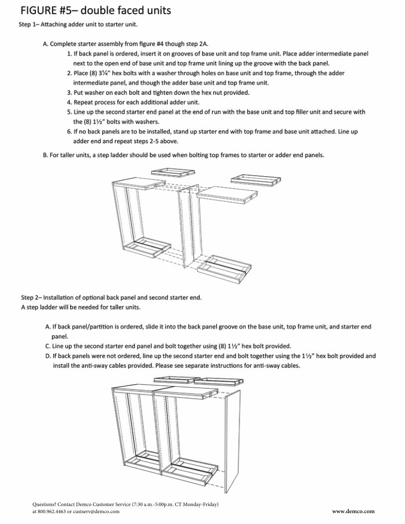
Step 2- Installation of optional back panel and second starter end.
A step ladder will be needed for taller units.
A. Stand up the starter panel with attached top frame and base units.
Base uni
t
8. If back panel is ordered, slide it into the back panel groove on the base unit, top frame unit, and starter end panel.
C. Line up the second starter end panel and bolt together usil\g 1 ½" hex bolt provided.
D. If back panels were not ordered, line up the second starter end and bolt together usil\g the 1 ½" hex bolt provided and
install the anti-sway cables provided. Please see separate instructions for anti-sway cables.
B 0
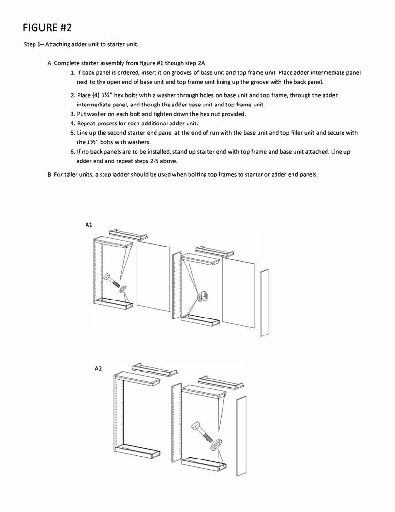
FIGURE #2
Step 1-Attaching adder unit to starter unit.
A. Complete starter assembly from figure #1 though step 2A.
1. If back panel is ordered, insert it on grooves of base unit and top frame unit. Place adder intermediate panel
next to the open end of base unit and top frame unit lining up the groove with the back panel.
2. Place (4) 3¼" hex bolts with a washer through holes on base unit and top frame, through the adder
intermediate panel, and though the adder base unit and top frame unit.
3. Put washer on each bolt and tighten down the hex nut provided.
4. Repeat process for each additional adder unit.
5. Line up the second starter end panel at the end of run with the base unit and top filler unit and secure with
the 1½" bolts with washers.
6. If no back panels are to be installed, stand up starter end with top frame and base unit attached. Line up
adder end and repeat steps 2-5 above.
8. For taller units, a step ladder should be used when bolting top frames to starter or adder end panels.
Al
A2
Questions? Contact Demco Customer Service (7:30 a.m.-5:00p.m. CT Monday-Friday)at 800.962.4463 or [email protected] www.demco.com