Gateway to a New Thinking in Energy Management - Ultracapacitors · 2005-01-24 · Gateway to a New...
64
Ultracapacitors Microelectronics High-Voltage Capacitors Gateway to a New Thinking in Energy Management - Ultracapacitors By: Maxwell Technologies - San Diego January 18 th , 2005
Transcript of Gateway to a New Thinking in Energy Management - Ultracapacitors · 2005-01-24 · Gateway to a New...

Ultracapacitors Microelectronics High-Voltage Capacitors
Gateway to a New Thinking in Energy Management - Ultracapacitors
By:
Maxwell Technologies - San DiegoJanuary 18th, 2005

Ultracapacitors Microelectronics High-Voltage Capacitors
About Maxwell
Capacitor Manufacturer since 1965
www.maxwell.com
Manufacturing facilities:US, Europe, Asia
Maxwell is a leading developer and manufacturer of innovative,
cost-effective energy storageand power delivery solutions.
Certifications:ISO 9001:2000ISO/TS 16949
ISO 9002

Ultracapacitors Microelectronics High-Voltage Capacitors
Table of Content
1. When can I use an Ultracapacitor?2. What is an Ultracapacitor?3. Ultracapacitor Market4. Ultracapacitor Applications5. Sizing your System6. Sizing Examples7. Guidelines to Designing an Ultracapacitor System8. Summary

Ultracapacitors Microelectronics High-Voltage Capacitors
When can I use an Ultracapacitor?
• Applications that require high reliability back-up power solutions
• Short term bridge power 1 - 60 seconds for transfer to secondary source or orderly shut down
• Power quality ride-through to compensate for momentary severe voltage sags
• Power buffer for large momentary in-rush or power surges

Ultracapacitors Microelectronics High-Voltage Capacitors
Power vs Energy
What is the difference between Power and Energy?

Ultracapacitors Microelectronics High-Voltage Capacitors
Application Model

Ultracapacitors Microelectronics High-Voltage Capacitors
Peak Power Shaving
Peak Power Shaving• Ultracapacitors provide peak power ...
AvailablePower
Required PowerUltracapacitor Peak Power

Ultracapacitors Microelectronics High-Voltage Capacitors
Back-up PowerBack-Up Power Support
• Ultracapacitors provide peak power…...and back-up power.
Required Power
Available Power Ultracapacitor Backup Power

Ultracapacitors Microelectronics High-Voltage Capacitors
What is an Ultracapacitor?

Ultracapacitors Microelectronics High-Voltage Capacitors
Ultracapacitor Performance Characteristics
• Ultracapacitors perform mid-way between conventional capacitors and electrochemical cells (batteries).
• Fast Charge and Fast Discharge Capability• Highly reversible process, 100,000’s of cycles• Lower energy than a battery
~10% of battery energy• Greater energy than electrolytic capacitors• Excellent low temperature performance

Ultracapacitors Microelectronics High-Voltage Capacitors
What is an Ultracapacitor?
Ultracapacitors are:A 100-year-old technology, enhanced by modern materialsBased on polarization of an electrolyte, high surface area electrodes and
extremely small charge separationKnown as Electrochemical Double Layer Capacitors and Supercapacitors
C = εr A/dMinimize (d)Maximize (A)
E = 1/2 CV2
Dielectric
Film foil Electrode
Electrolyte
ECDL
Separator

Ultracapacitors Microelectronics High-Voltage Capacitors
Technology Comparison
AvailablePerformance
Lead AcidBattery
Ultracapacitor ConventionalCapacitor
Charge Time 1 to 5 hrs 0.3 to 30 s 10-3 to 10-6 sDischarge Time 0.3 to 3 hrs 0.3 to 30 s 10-3 to 10-6 sEnergy (Wh/kg) 10 to 100 1 to 10 < 0.1Cycle Life 1,000 >500,000 >500,000Specific Power (W/kg) <1000 <10,000 <100,000Charge/discharge efficiency
0.7 to 0.85 0.85 to 0.98 >0.95

Ultracapacitors Microelectronics High-Voltage Capacitors
Technology Comparison (page 2)
0,01
0,1
1
10
100
1000
10 100 1000 10000
Power Density/[W/kg]
Ener
gy D
ensi
ty/[W
h/kg
]
Double-Layer Capacitors
10h 1h0,1h
36sec
3,6sec
0,36sec
36msec
Lead Acid Battery
Ni/Cd
Li-Battery
Al-Elco
U/C
Fuel Cells

Ultracapacitors Microelectronics High-Voltage Capacitors
0
1
2
3
4Efficiency
Self Discharge
Availability
Cycle Stability
Energy Density
Power Density
Energy Cost
Power Cost
System Cost
Safety
Recycling
Environment
Temperature Range
Charge AcceptanceUltracapsPb-AGMNiMHLi Ion
Ultracap vs Battery Technologies

Ultracapacitors Microelectronics High-Voltage Capacitors
Ultracapacitor Market

Ultracapacitors Microelectronics High-Voltage Capacitors
Ultracapacitor Market
Ultracapacitor World Market
Consumer Products
Digital CameraPDA
Toys
Memory back-up
UPSWindmill
Industrial
Stationary Fuel Cell
Automation/Robotics
Transportation
Hybrid Bus/TruckEngine starting
Light Hybrid
Local Power
Rail

Ultracapacitors Microelectronics High-Voltage Capacitors
Available Products
• Aqueous Electrolyte: ESMA, Elit, Evan, Skeleton Technologies and Tavrima
• Advantages:• High electrolytic conductivity• No need for tight closure to isolate • Low environmental impact
• Disadvantages:• Low decomposition voltage (1.23V)• Narrow operational range (freezing point of water)
• Organic Electrolyte: Maxwell Technologies, Panasonic, EPCOS, Ness Capacitors, ASAHI GLASS• Advantages:
• High decomposition voltage• Wide operating voltage
• Disadvantages:• Low electrolytic conductivity• Need for tight closure to isolate from atmospheric moisture

Ultracapacitors Microelectronics High-Voltage Capacitors
Ultracapacitor Applications

Ultracapacitors Microelectronics High-Voltage Capacitors
Applications
Automotive14/42 V systemsHEVElectrical Subsystems
TractionRegen brakingVoltage stabilizationDiesel engine starting
IndustryPower quality Pitch systemsActuators
Consumer ElectronicsAMRPDAsDigital cameras2-Way pagersScannersToys
Large Cells
Small Cells

Ultracapacitors Microelectronics High-Voltage Capacitors
Today’s Markets
Wind power plant pitch systemsBurst power
Small cell applicationsDigital cameras, AMR, Actuators, Memory boards
Electric Rail PackBraking Energy Recapture Diesel engine starting
TRACTION INDUSTRY CONSUMER

Ultracapacitors Microelectronics High-Voltage Capacitors

Ultracapacitors Microelectronics High-Voltage Capacitors
SITRAS® SES - Solution
Energy storage system: Stationnary or on the vehicle
Time t1Vehicle 1 is braking
Energy storage system stores thebraking energy
Time t2Vehicle 2 is acccelerating
Energy storage system delivers the energy
Application: Time shifted delivery of the stored braking energy for vehicle re-accelerationSolutions: Possible with either stationary or on-vehicle energy storage system
Advantage: Cost savings through reduced primary energy consumption

Ultracapacitors Microelectronics High-Voltage Capacitors
SITRAS® SES - Benefits
Saved energy
⇒ Reduction of the power need by 50 kW
⇒ Energy saving of 340.000 kWh per year and per installation
⇒ thermal limit68 kWh/h
04.08.01 07.08.01 10.08.01 13.08.01
50
40
30
20
10
0
kWh/h Saved energy
⇒ Reduction of the power need by 50 kW
⇒ Energy saving of 340.000 kWh per year and per installation
⇒ thermal limit68 kWh/h
04.08.01 07.08.01 10.08.01 13.08.01
50
40
30
20
10
0
kWh/h
04.08.01 07.08.01 10.08.01 13.08.01
50
40
30
20
10
0
kWh/h
Ultracapacitors Microelectronics High-Voltage Capacitors
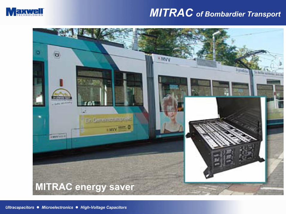
MITRAC of Bombardier Transport
MITRAC energy saver

Ultracapacitors Microelectronics High-Voltage Capacitors
Diesel Engine Cranking by Stadler
Ultracap module for diesel engine vehiclesRobust construction with voltage balancingEasy to scale up for additional cranking powerEasy to integrate in existing housingEasy to use, maintenance free

Ultracapacitors Microelectronics High-Voltage Capacitors
Wind Turbine Pitch Systems
Modern wind turbinesconsist of three-bladed variable speed turbines
Independent electro-mechanical propulsion units control and adjust the rotor-blades
Latest technology uses the wind not only to produce wind energy but also for its own safety

Ultracapacitors Microelectronics High-Voltage Capacitors
Pitch System Storage Systems
Each pitch systems is equipped with an ultracapacitor emergency power supply
Ultracapacitors represent an optimum emergency power supply system due to their• Enhanced level of
safety• High reliability• Efficiency• Scalability
Switch box including 2600F ultracapacitors
75 V, 81 F ultracapacitor module
4 modules are put in series to power 300 V
pitch systems of 3-5 MW wind power plants

Ultracapacitors Microelectronics High-Voltage Capacitors
Fuel Cell Powered Fork Lift
• BOOSTCAP module:48 BCAP0010112 V, 55 F40 kW peak power
• Fork lift equipped with a fuel cell
• Cell system and an ultracapacitor module

Ultracapacitors Microelectronics High-Voltage Capacitors
Vehicle Applications of Ultra-capacitors
• Distributed energy modules are located at the actuator level in the vehicle control hierarchy in close proximity to the actuator power driver (should be within 18”).
Vehicle SystemController
ISG SubsystemBelt or Crankshaft
Engine Transmission
High VoltageBattery Primary Storage
Other 42VLoads
Brake actuators
ETC, Fan, Water Pump
ISGTorque
Gear Sel, L/U ClutchOil Pump
SOC, SOH,Vsys
Continuous,Scheduled,Selectable
BrakesRegen Brake Sys
Steeringelectric assist
Steering actuator
UC UCUC
ECU
MtrRac
k ECU
HCU
ECU
Mtr ThrottleBody
SteeringWheel
BrakePedal
AccelPedal
Power & Communications (PDA)
DistributedEnergy StorageModules
Energy StorageSystem Mgm't
UC UC
ECU
HVAC
Electric aircond. comp.

Ultracapacitors Microelectronics High-Voltage Capacitors
Fuel Cells with Ultracapacitors
Ultracapacitors are accepted as the normal energy storage option for fuel cells
• Every major automotive company in the world is testing fuel cells as an alternative drive train power system.
• All significant fuel cell companies are either using or experimenting with ultracapacitors as an integral part of the system.
• Several major automotive companies have declared fuel cells with ultracapacitors as their baseline system architecture. Honda and Hyundai have gone public, others we are working with have not.
“Utilizing ultracapacitors we have gained an edge in energy efficiency and throttle responsiveness over competitors that are pursuing the hybrid battery–fuel cell model”Honda Motor Company

Ultracapacitors Microelectronics High-Voltage Capacitors
Sizing Your System

Ultracapacitors Microelectronics High-Voltage Capacitors
Data sheet

Ultracapacitors Microelectronics High-Voltage Capacitors
Data sheet

Ultracapacitors Microelectronics High-Voltage Capacitors
How to measure Ultracapacitors
• To measure UC you need:• bi-directional power supply (supply/load) OR• separate power supply and programmable load (constant current capable)• voltage vs. time measurement and recording device (digital scope or other data
acquisition)
• Capacitance and Resistance:Capacitance = (Id * td)/(Vw - Vf) = (Id * td)/Vd
ESR = (Vf - Vmin)/Id
Vw = initial working voltage Vmin = minimum voltage under loadId = discharge current Vf = voltage 5 seconds after removal of load.td = time to discharge from initial voltage to minimum voltage

Ultracapacitors Microelectronics High-Voltage Capacitors
Basic Equations
Definition of Capacitance: C = Q/V (1)
Charge = current * time: Q = I*t C = I*t/V (1a)
Solving for voltage: V = I*t/C (2)
Dynamic Voltage: dV/dt = I/C (3)
Stored Energy E = ½ C*V2(4)
At initial voltage Vo, Eo = ½ C*Vo2
At final voltage Vf, Ef = ½ C*Vf2
Delivered energy = Eo – Ef ∆E =½ C*(Vo2 – Vf
2) (5)
Ultracapacitors Microelectronics High-Voltage Capacitors
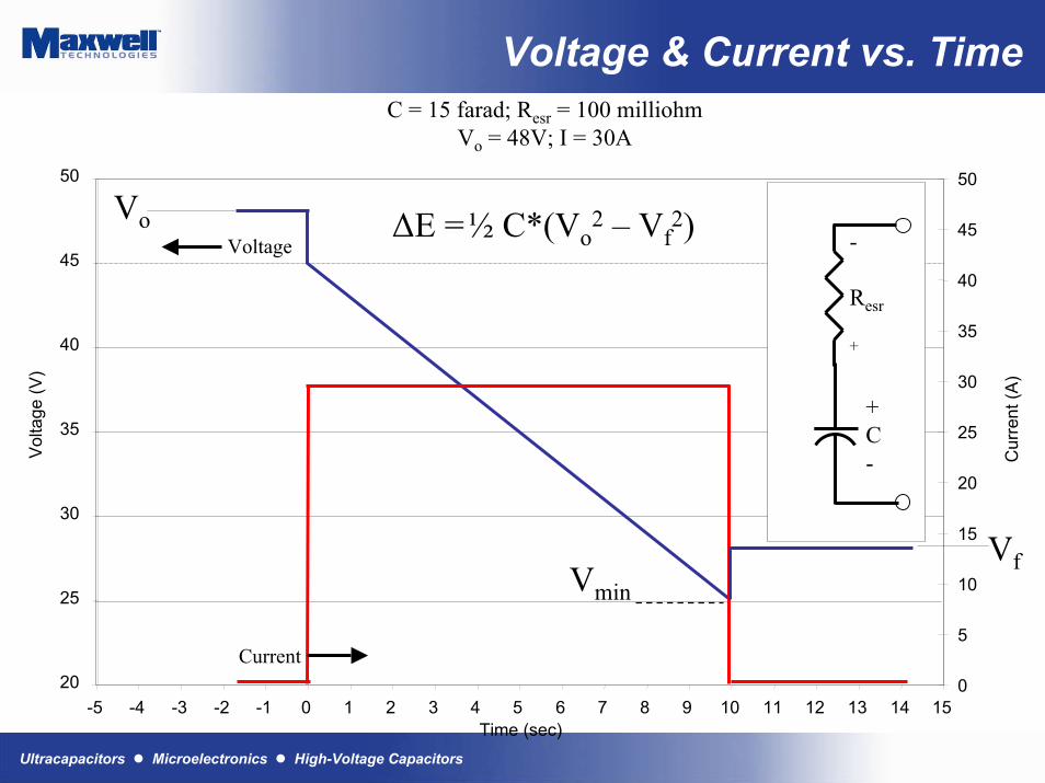
Voltage & Current vs. TimeC = 15 farad; Resr = 100 milliohm
Vo = 48V; I = 30A
-5 -4 -3 -2 -1 0 1 2 3 4 5 6 7 8 9 10 11 12 13 14 15Time (sec)
20
25
30
35
40
45
50
Vol
tage
(V)
0
5
10
15
20
25
30
35
40
45
50
Cur
rent
(A)
-
Resr
+
+C-
i
Voltage
Current
Vo
Vmin
Vf
V = Q/CdVesr = I*ResrdV/dt = I/C ; dV = I*dt/CdVtotal = I*dt/C + I*Resr∆E =½ C*(Vo2 – Vf
2)

Ultracapacitors Microelectronics High-Voltage Capacitors
Basic Model
• Series/Parallel configurations• Changes capacitor size; profiles are the same• Series configurations
• Capacitance decreases, Series Resistance increases• Cs=Ccell/(#of cells in series) Rs=Rcell*(# of cells in series)
• Parallel configurations• Capacitance increases, Series Resistance decreases• CP=Ccell*(# of cells in parallel) RP=Rcell/(# cells in parallel)
• Current controlled• Use output current profile to determine dV/dt
dV = I * (dt/C + ESR)• Power controlled
• Several ways to look at this:Pterm = I*Vcap –I2*ESR (solve quadratic for I)I = [Vcap - sqrt(Vcap
2-4*ESR*Pterm)]/(2*ESR)• Solve for dV/dt as in current-controlled• J=W*s=1/2CV2 Solve for C.

Ultracapacitors Microelectronics High-Voltage Capacitors
Applications with a singleenergy storage component
• Applications in which little total energy is required (i.e. memory backup)
• Possibly used with other energy sources• Short duration, high power (i.e. pulse transmit)• Long duration, low power (i.e UPS backup)• Opportunities for high charge rates (i.e toys)

Ultracapacitors Microelectronics High-Voltage Capacitors
Applications with twoenergy storage components
• Power vs. Energy design tradewhen using two components• Single component vs. two components
• Engines/Fuel cells/Batteries/Solar Arrays are energy rich/power poor (or poor response)
• Size these components for enough energy, system may be limited in power
• Size these components for power, system may have surplus of energy• Ultracapacitors are power rich/energy poor
• Size an ultracapacitor for enough energy, system may have a surplus of power
• Size an ultracapacitor for power, system may be limited in energy
• Two components• A primary source for energy; Ultracapacitor for power• Requires appropriate definition of peak power vs. continuous power

Ultracapacitors Microelectronics High-Voltage Capacitors
Ultracapacitor Aging
• Unlike batteries, Ultracapacitors do not have a hard end of life criteria.
• Ultracapacitors degradation is apparent by a gradual loss of capacitance and a gradual increase in resistance.
• End of life is when the capacitance and resistance is out of the application range and will differ depending on the application.
• Therefore life prediction is easily done.

Ultracapacitors Microelectronics High-Voltage Capacitors
Capacitance and ESR vs Frequency
ESR vs . Frequency
0,00E+00
1,00E-04
2,00E-04
3,00E-04
4,00E-04
5,00E-04
6,00E-04
7,00E-04
1,00E-02 1,00E-01 1,00E+00 1,00E+01 1,00E+02 1,00E+03Frequency [Hz]
ESR
[mO
hm]
Capacitance vs. Frequency
0,00E+00
5,00E+02
1,00E+03
1,50E+03
2,00E+03
2,50E+03
3,00E+03
3,50E+03
1,00E-02 1,00E-01 1,00E+00 1,00E+01 1,00E+02 1,00E+03
Frequency [Hz]
Cap
acita
nce
[F]
Ultracapacitors Microelectronics High-Voltage Capacitors
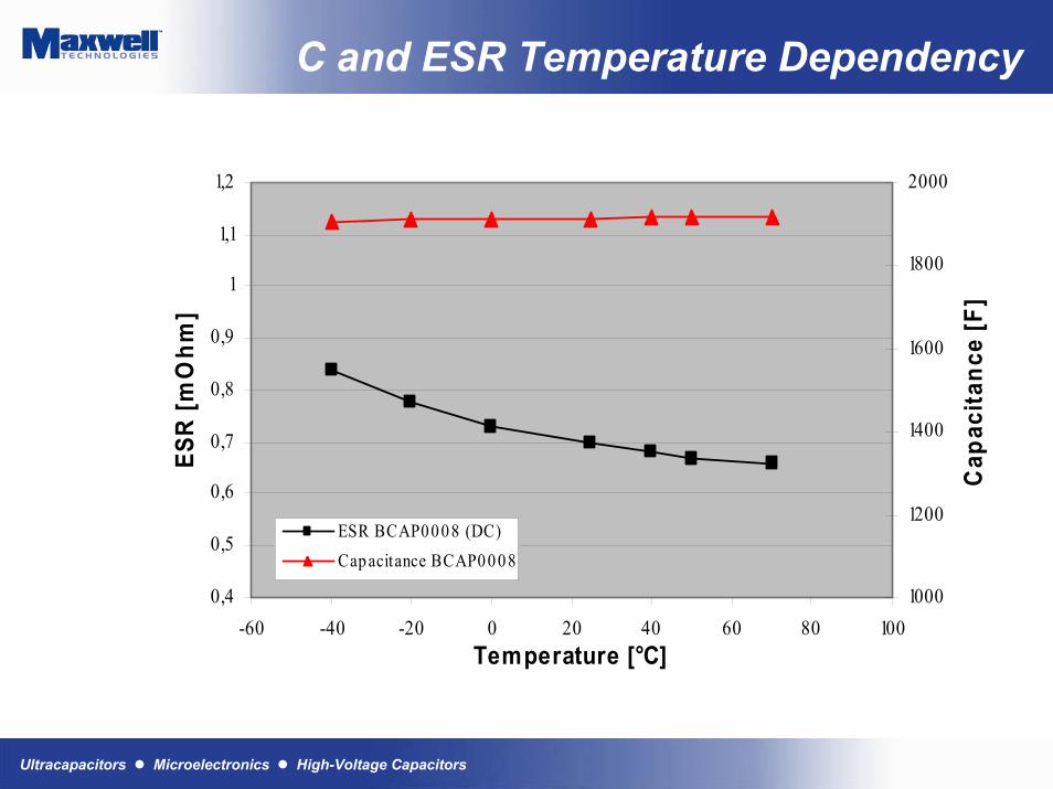
C and ESR Temperature Dependency
0,4
0,5
0,6
0,7
0,8
0,9
1
1,1
1,2
-60 -40 -20 0 20 40 60 80 100Temperature [°C]
ESR
[mO
hm]
1000
1200
1400
1600
1800
2000
Cap
acita
nce
[F]
ESR BCAP00 0 8 (DC)Cap acitance BCAP0 0 0 8

Ultracapacitors Microelectronics High-Voltage Capacitors
BCAP Self Discharge
Self Discharge vs Temperature
30,0
40,0
50,0
60,0
70,0
80,0
90,0
100,0
0 2 4 6 8 10 12 14 16 18 20 22 24 26 28 30
Time [days]
% U
(t =
0)
- 35 °C
+ 5 °C
+ 25 °C
+ 65 °C

Ultracapacitors Microelectronics High-Voltage Capacitors
BCAP Cycling Capacity
90 A CC, 1.15-2.3 V, 25 s, RT
50.0
60.0
70.0
80.0
90.0
100.0
110.0
0 20000 40000 60000 80000 100000
Cycle Number
Cha
nge
in C
apac
itanc
e [%
]
0.0E+002.0E-044.0E-046.0E-048.0E-041.0E-031.2E-031.4E-031.6E-031.8E-032.0E-03
ESR
[Ohm
]
ESR
Capacitance

Ultracapacitors Microelectronics High-Voltage Capacitors
BCAP Cycling
500’000 cycles between 1.8 and 2.7 V, 100 AESR (1 Hz) increase 140 % (0.49 to 0.79 mOhm Capacitance decrease 38 % (2760 to 1780 F), 30% compared to rated capacitance

Ultracapacitors Microelectronics High-Voltage Capacitors
BCAP DC Life
Capacitance and ESR variation at U, T = 40 °C
50,0
55,0
60,0
65,0
70,0
75,0
80,0
85,0
90,0
95,0
100,0
105,0
0,0 100,0 200,0 300,0 400,0
duration [days]
% C
(t =
0)
2.5V 40°C
2.1V 40°C
2.3V 40°C
-40,0
-20,0
0,0
20,0
40,0
60,0
80,0
100,0
120,0
140,0
160,0
180,0
200,0
0,0 100,0 200,0 300,0 400,0duration [days]
% E
SR (t
= 0)
2.5V 40°C2.1V 40°C2.3V 40°C

Ultracapacitors Microelectronics High-Voltage Capacitors
BCAP DC Life
0,0
20,0
40,0
60,0
80,0
100,0
120,0
0 100 200 300 400
duration [days]
% C
(t =
0)
2.1V 65°C2.3V 65°C2.5V 65°C
-40,0
-20,0
0,0
20,0
40,0
60,0
80,0
100,0
120,0
0 100 200 300 400duration [days]
% E
SR (t
= 0)
2.5V 65°C2.1V 65°C2.3V 65°C
Capacitance and ESR variation at U, T = 65 °C

Ultracapacitors Microelectronics High-Voltage Capacitors
Sizing Examples

Ultracapacitors Microelectronics High-Voltage Capacitors
Example sizing
1) Define System Requirements15 W delivered for 10 seconds10V max; 5V min
2) Determine total energy needed: J=WS=10W*10sec=150Ja) Determine Capacitance based on: J=1/2CV2
b) Substitute the energy from above: 150J=1/2C(Vmax2-Vmin
2)c) Solve for C: C=300/(102-52)=4F
3) Add 20-40% safety margin to cover I2R losses Csystem = 4.8F4) Calculate number of cells in series (since maximum cell voltage = 2.5V)
10V/2.5V = 4 cells in series5) Calculate cell-level capacitance
C = Csys * # of series cells = 4.8F* 4 = 19.2F per 2.5V “cell”6) Calculate number of cells in parallel (we will assume a 10F cell)
# in parallel = 19.2/10F = 2 x 10F cells in parallel

Ultracapacitors Microelectronics High-Voltage Capacitors
Guidelines to Designing an Ultracapacitor System
Ultracapacitors Microelectronics High-Voltage Capacitors
Ultracapacitor Cell Balancing
Why Cell Balancing?
• Achieve cell to cell voltage balance
• Accounts for variations in capacitance and leakage current, initial charge and voltage dependent on capacitance, sustained voltage dependent on leakage current
• Reduces voltage stress on an individual cell
• Increase overall reliability of the individual cells

Ultracapacitors Microelectronics High-Voltage Capacitors
Ultracapacitor Cell Balancing
How to Cell Balance?
• Resistor method, resistor placed in parallel, resistor value calculated at 10x leakage current for slow balance, 100x for faster balance, good for low cycle when efficiency or stand by loss not an issue
Surface Mount Resistor for low
duty cycle application
Ultracapacitors Microelectronics High-Voltage Capacitors
Ultracapacitor Cell Balancing
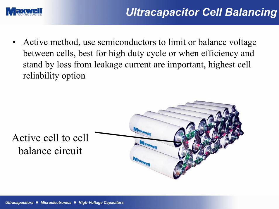
• Active method, use semiconductors to limit or balance voltage between cells, best for high duty cycle or when efficiency and stand by loss from leakage current are important, highest cell reliability option
Active cell to cell balance circuit

Ultracapacitors Microelectronics High-Voltage Capacitors
Cell Balancing2600F cells; 4 in Series• Low Cost
• Scalable balance current• 10mA, 300mA circuits
• Very low quiescent current (<20µA)• No on/off required
• Modular installation• N cells requires N-1 circuits
• Voltage independent
Low capacitance,high leakage cell
Note high and low points;
low capacitance cell
1.5 hours of Vehicle cycling (~ 200A)
300mA balancer for 50 & 60mm Ø cells
10mA balancer for 5F & 10F cells

Ultracapacitors Microelectronics High-Voltage Capacitors
Cell Balancing
+
-
R3
R4
C2
C11M 1%
1M 1%
R1
R2
VPP
VNN
U1
499k 1%
475 1%Ultracapacitors
C1 Positive
C1-C2 Midpoint
C2 Negativ e
POS
NEG
+
-U1
VNN
VPP
R1100K 1%
R2100K 1%
R6
5.6 1% 1.5W
R549.9k 1%
C2
C1
Ultracapacitors
C1 Positive
C1-C2 Midpoint
C2 Negative
POS
NEG
Q1
Q2
TLV2211CDBV
R3
100
R4
100
MMBT2222AWT1
MMBT2907AWT1
10mA Balancer
300mA Balancer

Ultracapacitors Microelectronics High-Voltage Capacitors
Cell Balancing
Three cells with one cell balancing resistor removed:OCTA Cycles Max. Voltage Profiles
0.00
0.50
1.00
1.50
2.00
2.50
3.00
3.50
4.00
4.50
5.00
0 1 2 3 4 5 6 7 8 9 10
Day #
Cel
l vol
tage
(V)
C1-V
C2-V
C3-V

Ultracapacitors Microelectronics High-Voltage Capacitors
Ultracapacitor Packaging
Why Packaging?
• Ensure proper mechanical stress• Ensure robust low resistance interconnect• Ensure proper electrical isolation• Ensure proper thermal considerations• Ensure agency compliance• Increase overall cell reliability• Reduce or eliminate maintenance requirements

Ultracapacitors Microelectronics High-Voltage Capacitors
Ultracapacitor Packaging
How to Package Cells?
• Care should be taken for the electrical interconnect, a few key guidelines to follow:
• Do not over torque. Over torque at the terminals may cause internal failure of contact points. For example, the Maxwell BCAP specification is 100 in.-lbs
• Use similar conductor metal interconnect bus bars to eliminate galvanic corrosion.
• Good surface to surface contact will reduce inter-cell resistance, reducing voltage drop and temperature stress

Ultracapacitors Microelectronics High-Voltage Capacitors
Ultracapacitor Packaging
How to Package Cells?
• Cell to cell spacing should take into consideration two key points and can be accomplished by the design of the interconnect or the cell balancer:
• Depending on the cell some part of the outer case may be electrically the same as one of the terminals, ensure electricalisolation and watch for rubbing components that may wear through ultracapacitor insulation, do not remove the factory installed insulator sleeve
• Some air space between the cells allows convection cooling via air flow improving reliability, depends on cycle time, short duration high cycle applications may require forced air or othercooling method

Ultracapacitors Microelectronics High-Voltage Capacitors
Ultracapacitor Packaging
Proper Torqueand Hardware
ElectricalIsolation
Aluminum Interconnect

Ultracapacitors Microelectronics High-Voltage Capacitors
Summary

Ultracapacitors Microelectronics High-Voltage Capacitors
Benefits Summary
Calendar Life• Function of average voltage and temperature
Cycle Life• Function of average voltage and temperature
Charge acceptance• Charge as fast as discharge, limited only by heating
Temperature• High temp; no thermal runaway• Low temp; -40°C

Ultracapacitors Microelectronics High-Voltage Capacitors
Benefits Summary
No fixed Voc• Control Flexibility; context-dependent voltage is permitted• Power Source voltage compatibility
• Examples; Fuel cells, Photovoltaics
No Vmin• Cell can be discharge to 0V.• Control Safety; No over-discharge• Service Safety
Cell voltage management• Only required to prevent individual cell over-voltage
State of Charge & State of Health• State of Charge equals Voc
• Dynamic measurements for C and ESR = State of Health• No historical data required
Ultracapacitors Microelectronics High-Voltage Capacitors
Useful Links
• Useful links on Maxwell Technologies Web-site:• White Papers• Technology Overview• Sizing worksheet• Application Notes• Data Sheets
www.maxwell.com