GATE- IN 2007
30
2007 IN IN 1/30 www.gatehelp.com Q.1 - Q.20 carry one mark each. Q.1 Let A be an n n # real matrix such that A I 2 = and y be an n -dimensional vector. Then the linear system of equations Ax y = has (A) No solution (B) A unique solution (C) More than one but finitely many independent solutions (D) Infinitely many independent solutions Q.2 Let j 1 = − . Then one value of j j is (A) j (B) 1 − (C) 2 π (D) e /2 π − Q.3 In full sunlight, a solar cell has a short circuit current of 75 mA and a current of 70 mA for a terminal voltage of 0.6 with a given load. The Thevenin resistance of the solar cell is (A) 8Ω (B) 8.6 Ω (C) 120 Ω (D) 240 Ω Q.4 The DC voltage gain V V i 0 in the following circuit is given by (A) A R R R v 1 2 2 + (B) A R R R v 1 2 1 + (C) A R R R R v 1 2 2 0 + + (D) A v Q.5 Match the essential amplifier characteristics with the sensing applications given below :
-
Upload
prabhjot-singh1 -
Category
Documents
-
view
222 -
download
0
Transcript of GATE- IN 2007

7/27/2019 GATE- IN 2007
http://slidepdf.com/reader/full/gate-in-2007 1/30
2007 IN
IN 1/30
www.gatehelp.com
Q.1 - Q.20 carry one mark each.
Q.1 Let A be an n n # real matrix such that A I 2 = and y be an n -dimensional vector.Then the linear system of equations Ax y = has
(A) No solution
(B) A unique solution
(C) More than one but finitely many independent solutions
(D) Infinitely many independent solutions
Q.2 Let j 1= − . Then one value of j j is
(A) j (B) 1−
(C) 2π (D) e /2π−
Q.3 In full sunlight, a solar cell has a short circuit current of 75 mA and a current of 70mA for a terminal voltage of 0.6 with a given load. The Thevenin resistance of the solarcell is
(A) 8Ω (B) 8.6 Ω
(C) 120 Ω (D) 240 Ω
Q.4 The DC voltage gain V V
i
0 in the following circuit is given by
(A) A R RR
v 1 2
2+ (B) A R R
Rv
1 2
1+
(C) A R RR Rv
1 2
20+ + (D) A v
Q.5 Match the essential amplifier characteristics with the sensing applications given below:

7/27/2019 GATE- IN 2007
http://slidepdf.com/reader/full/gate-in-2007 2/30
2007 IN
IN 2/30
www.gatehelp.com
Amplifier CharacteristicsP. Charge amplifier with very
low bias current and highinput impedance.
Q. Voltage amplifier with lowbias current and very highinput impedance.
R. Voltage amplifier with veryhigh CMRR.
Sensing Applications
L Strain gauge in unipolar DCWheatstone bridge.
M Glass electrode pH sensor.
N Piezoelectric sensor for mea-surement of static force
(A) P-L, Q-M, R-N (B) P-M, Q-N, R-L
(C) P-N, Q-L, R-M (D) R-N, Q-M, R-L
Q.6 The figure below shows various configuration of bonding a strain gauge to a cantileversubjected to a bending force F.
Which configuration given the maximum change in resistance for this force ?
(A) P(B) Q
(C) R
(D) All have equal change in resistance

7/27/2019 GATE- IN 2007
http://slidepdf.com/reader/full/gate-in-2007 3/30
2007 IN
IN 3/30
www.gatehelp.com
Q.7 When light falls on the photodiode shown in the following circuit, the reverse satura-tion current of the photodiode changes from 100 μA to 200 μA.
Assuming the op-amp to be ideal, the output voltage, V out of the circuit(A) Does not change (B) Change from 1V to 2 V
(C) Changes from 2V to 1V (D) Changes from 1 − V to 2−
Q.8 A 555 astable multivibrator circuit is shown in the figure below :
If R B is shorted, the waveform at V C is

7/27/2019 GATE- IN 2007
http://slidepdf.com/reader/full/gate-in-2007 4/30
2007 IN
IN 4/30
www.gatehelp.com
Q.9 A Clark oxygen sensor is a
(A) Potentiometric sensor (B) Amperometric sensor
(C) Conductometric sensor (D) Magnetostrictive sensor
Q.10 A logic circuit implements the boolean function F X Y X Y Z : : := + . It is foundthat the Combination X Y 1= = can never occur. Taking this into account, a simplifiedexpression for F is given by.
(A) X Y Z :+ (B) X Z +
(C) X Y + (D) .Y X Z +
Q.11 A CMOS implementation of a logic gate is shown in the following figure :
The boolean logic function realized by the circuit is(A) AND (B) NAND
(C) NOR (D) OR
Q.12 Let ( )x t be a continuous-time, real-valued signal band-limited to F Hz. The Nyquistsampling rate, in Hz, for ( ) ( . ) ( ) ( )y t x t x t x t 0 5 2= + − is
(A) F (B) 2F
(C) 4F (D) 8F
Q.13 Consider the periodic signal ( ) ( . )cos cosx t t t 1 0 5 40 200π π= + , where t is in seconds.Its fundamental frequency, in Hz, is
(A) 20 (B) 40
(C) 100 (D) 200

7/27/2019 GATE- IN 2007
http://slidepdf.com/reader/full/gate-in-2007 5/30
2007 IN
IN 5/30
www.gatehelp.com
Q.14 A dynamometer type wattmeter with a single scale marked for the smallest powerrange, has two current ranges, namely, 0-5 A and 0.10 A well as two voltage ranges,namely, 0-150 V and 0.300 V. To carry out a load test on a 230 V/115 V, 1kVA, singlephase transformer, the wattmeter is used on the high voltage side. The voltage and cur-rent ranges are chosen for maximum utilization of the scale. The multiplying factor to be
used in this case is.(A) 0.5 (B) 1.0
(C) 2.0 (D) 4.0
Q.15 Consider the AC bridge shown in the figure below, with A, L and C having positivefinite values.
Then
(A) V 00 = if L C 1ω ω= (B) V 00 = if L C =
(C) V 00 = if R LC 1
= ω (D) V 0 cannot be made zero
Q.16 A feedback control system with high gain K, is shown in the figure below :
Then the closed loop transfer function is(A) sensitive to perturbations in G(s) and H(s)
(B) sensitive to perturbations in G(s) but not to perturbations in H(s)
(C) sensitive to perturbations in H(s) but not to perturbations in G(s).
(D) insensitive to perturbations in G(s) and H(s).

7/27/2019 GATE- IN 2007
http://slidepdf.com/reader/full/gate-in-2007 6/30
2007 IN
IN 6/30
www.gatehelp.com
Q.17 Consider the following standard state-space description of a linear time-invariantsingle input single output system : x Ax Bu = + , y Cx Du = + . Which one of the followingstatements about the transfer function CANNOT be true if D 0=Y ?
(A) The system is unstable (B) The system is strictly proper
(C) The system is low pass (D) The system is of type zero
Q.18 During intravascular measurment of arterial blood pressure, catheters may be intro-duced in different configurations as shown in the figures below :
The static pressure will be measured correctly in the configuration (s)(A) P and Q but not in R (B) R only
(C) Q only (D) P and R but not in Q
Q.19 In N 2-washout estimation of lung volume using spirometry, the lung volumes at thebeginning and the end of the washout are the same. Let T, V, and F denote temperature,
volume and molar fraction (of N 2) respectively; subscripts S and L denote the spirometerand the lung; and t 1 and t 2 the beginning time and the end time of the experiment, re-spectively.
Then
(A) ( ) ( )( ) ( )V T
T F t F t
F t V t L
S
L
L L
s s
1 2
2 2= −= G (B) ( ) ( )( ) ( )V T
T F t F t
F t V t L
S
L
L L
L S
1 2
2 2= −= G(C) ( ) ( )V F t V t L L L1 2= (D) ( ) ( )V T F t V t L S S S 2 2=
Q.20 The dispersion in an X-ray diffractometer,d
d
λ
θ , is given by the expression
(A) cosd m
2 θ (B) sind m
2 θ(C) sind 2 θ (D) cosd 2 θ
Q.21 to Q.75 carry two marks each.

7/27/2019 GATE- IN 2007
http://slidepdf.com/reader/full/gate-in-2007 7/30
2007 IN
IN 7/30
www.gatehelp.com
Q.21 The polynomial ( )p x x x 25= + + has
(A) all real roots (B) 3 real and 2 complex roots
(C) 1 real and 4 complex roots (D) all complex roots
Q.22 Let [ ]A a ij = , ,i j n 1 # # , with n 3$ and .a i j ij = . Then the rand of A is
(A) 0 (B) 1
(C) n 1− (D) n
Q.23 For real x , the maximum value of e e
cos
sin
x
x
is
(A) 1 (B) e
(C) e 2
(D)3
Q.24 Consider the function ( ) f x x 3= , where x is real. Then the function ( ) f x at x 0= is
(A) Continuous but not differentiable
(B) Once differentiable but not twice
(C) Twice differentiable but not thrice
(D) Thrice differentiable
Q.25 The value of the integral e e x y
00
2 233 − − # # dx dy is
(A) 2π (B) π
(C) π (D) 4π
Q.26 For the function sinz
z 3 of a complex variable z , the point z 0= is
(A) a pole of order 3 (B) a pole or order 2
(C) a pole or order 1 (D) not a singularity
Q.27 Assume that the duration in minutes of a telephone conversation follows the expo-nential distribution ( ) , f x e x 5
1 0/x 5 $= . The probability that the conversation will exceedfive minutes is.
(A) e 1 (B) e 1 1−

7/27/2019 GATE- IN 2007
http://slidepdf.com/reader/full/gate-in-2007 8/30
2007 IN
IN 8/30
www.gatehelp.com
(C)e 12 (D)
e 1 1
2−
Q.28 The boundary-value problem , ( ) ( )y y y y 0 0 0n λ π+ = = = will have non-zero solu-tion is and only if the values of λ are
(A) , , , ........0 1 2! ! (B) , , , ......1 2 3
(C) , , , .......1 4 9 (D) , , , .......1 9 25
Q.29 Identify the Newton-Raphson iteration scheme for finding the square root of 2.
(A) x x x 21 2
n n n
1 = ++ b l (B) x x x 21 2
n n n
1 = −+ b l(C) x x
2n
n 1 =+ (D) x x 2n n 1 = ++
Q.30 Consider the linear circuit with and ideal op-amp shown in the figure below.
The Z-parameters of the two port feedback network are 11Z Z k11 22 Ω= = and 1Z Z k12 21 Ω= =. The gain of the amplifier is(A) 1 01+ (B) 11+
(C) 1− (D) 120−
Q.31 Consider a non-ideal voltage source whose output voltage is measured by a non-idealvoltmeter as shown below.
Let V e be the difference between V s and the measured voltage.

7/27/2019 GATE- IN 2007
http://slidepdf.com/reader/full/gate-in-2007 9/30
2007 IN
IN 9/30
www.gatehelp.com
The V V e
sis a function of
(A) R m only (B) R s only
(C) RR
m
s (D) R Rm s−
Q.32 Two sensors have measurement errors that are Gaussian distributed with zero meansand variance 1
2σ and 22σ , respectively. The two sensor measurements x 1 and x 2 are combined
to form the weighted average ( ) ,x x x 1 0 11 2 # #α α α= + − . Assuming that the measure-ment errors of the sensors are uncorrelated, the weighting factor α that yields the smallesterror variance of x is
(A)12
22
22
σ σσ+
(B)12
22
12
σ σσ+
(C)1 2
2
σ σσ+
(D) 0.5
Q.33 Two square waves of equal period T, but with a time delay τ are applied to a digitalcircuit whose truth table is shown in the following figure.
The high and the low levels of the output of the digital circuit are 5 V and 0 V, respectively.Which one of the following figures shows the correct variation of the average value of theoutput voltage as a function of τ for ( / )t T 0 2# # ?

7/27/2019 GATE- IN 2007
http://slidepdf.com/reader/full/gate-in-2007 10/30
2007 IN
IN 10/30
www.gatehelp.com
Q.34 In the circuit shown in the following figure, the current through the 1 Ω resistor is
(A) ( )cos t A1 5 2+ (B) ( )cos t A5 2+
(C) (1 5 2 )cos t A− (D) A6
Q.35 In the circuit shown in the following figure, the switch is kept closed for a long timeand then opened at t 0= .
The values of the current i just before opening the switch ( )t 0= − and just after theopening the switch ( )t 0= + are, respectively
(A) A43 and A1 (B) A4
3 and A45
(C) A1 and 67 A (D) A1 and A1
Q.36 Consider the coupled circuit shown below.

7/27/2019 GATE- IN 2007
http://slidepdf.com/reader/full/gate-in-2007 11/30
2007 IN
IN 11/30
www.gatehelp.com
At angular frequency ω, this circuit can be represented by the equivalent T-network,shown below.
Indicate the correct set of expressions for the impedances of the T-network.(A) ( )Z j L M 1 1 12ω= − (B) ( )Z j L M 1 1 12ω= +
( )Z j L M 2 2 12ω= − ( )Z j L M 2 2 12= +ω
Z j M 3 12ω= Z j M 3 12ω=
(C) Z j L1 1ω= (D) ( )Z j L M 1 1 12ω= −
Z j L2 2ω= ( )Z j L M 2 2 12ω= −
Z j M 3 12ω=− ( )Z j L L M 3 1 2 12ω= + +
Q.37 A FET source follower is shown in the figure below
The nature of feedback in this circuit is(A) Positive current (B) Negative current
(C) Positive voltage (D) Negative voltage
Q.38 In the circuit shown below, .V V 0 7BE = .

7/27/2019 GATE- IN 2007
http://slidepdf.com/reader/full/gate-in-2007 12/30
2007 IN
IN 12/30
www.gatehelp.com
Te β of the transistor and V CE are, respectively
(A) 19 and 2.8 V (B) 19 and 4.7 V
(C) 38 and 2.8 V (D) 38 and 4.7 V
Q.39 A well of cross-sectional area a ω is connected to an inclined tube of cross-sectionalarea a t to form a differential pressure gauge as shown in the figure below. When p p1 2= the common liquid level is denoted by A. When p p>1 2, the liquid level in the well is de-pressed to B, and the level in the tube rises by l along its length such that the differencein the tube and well levels is h d .
The angle of inclination θ of the tube with the horizontal is
(A) sin h a a 1
d t
1 − ω− : D (B) sin l h
a a d t 1 +
ω
− : D(C) sin l
h a a d t 1 −
ω
− : D (D) sin l h
a a d
t
1 + ω− : DQ.40 The accompanying figure shows a VERTICAL venturimeter with upward water flow.When the measured static pressure difference p p1 2− , between the inlet and the throat is30 kPa, the flow rate is found to be 50 liters per second. Assume that the coefficient of discharge remains the same.

7/27/2019 GATE- IN 2007
http://slidepdf.com/reader/full/gate-in-2007 13/30
2007 IN
IN 13/30
www.gatehelp.com
When p p 201 2− = kPa, the flow rate in litres per second, is(A) 33.3 (B) 39.3
(C) 40.8 (D) 54.2
Q.41 A thermometer with time constant τ , initially at the ambient temperature, is used tomeasure the temperature of a liquid in a both. The excess temperature of the thermometerand the liquid over the ambient are ( ) t θ and ( )t l θ , respectively, where t denotes the time.If ( )t kt l θ = , where k is a constant, the steady state error, defined as [ ( ) ( )]lim t t
t l θ θ−
" 3, is
(A) 3 (B) 0
(C) k − (D) k τ−
Q.42 In a laminar flow experiment, Fluid A is pumped through a straight tube and thevolumetric flow rate and pressure drop per unit length are recorded. In a second straighttube having twice the internal diameter of the first one, Fluid B records the same pres-sure drop per unit length at the same volumetric flow rate. Assuming fully developed flowconditions in the tubes, the ratio of the dynamic viscosity of Fluid B to that of Fluid A is
(A) 16 (B) 32
(C) 64 (D) 128
Q.43 A thermistor has a resistance of 10 k Ω at 25 C c and k 1 Ω at C 100c . The range of operation is C C 0 150c c− The excitation voltage is 5V and a series resistor of k 1 Ω is con-nected to the thermistor.

7/27/2019 GATE- IN 2007
http://slidepdf.com/reader/full/gate-in-2007 14/30
2007 IN
IN 14/30
www.gatehelp.com
The power dissipated in the thermistor at C 150c is(A) 4.0 mW (B) 4.7 mW
(C) 5.4 mW (D) 6.1 mW
Q.44 A measurement system for the rotational speed of a motor is shown in the figurebelow. The system consists of an opaque dish attached to the motor shaft with a hole asshown. A light source and a photodetector are placed on two sides of the disk so that thewhenever the hole cross the light path, photodetector receives light through the hole. The
photodetector circuit is also shown below. Assume sufficient light intensity and TTL logiclevels for the inverter.
The output the photodetector is a(A) Triangular wave
(B) Square wave with 50% duty cycle
(C) Rectangular wave with duty cycles close to unity
(D) Rectangular wave with duty cycle close to zero
Q.45 A pH electrode, being used at C 25c , has a source resistance of 1010Ω . The electrodeobeys the Nernst equation perfectly. The electronic voltmeter, with which the potentialis being measured, has an input impedance of 10 11Ω and a gain of 100. If the pH of theanalyte changes from 6.5 to 7.8, the change in voltage observed on the voltmeter is
(A) less than 6.8 V (B) between 6.8 V and 7.19 V
(C) Between 7.2 V and 7.49 V (D) Greater than 7.49 V

7/27/2019 GATE- IN 2007
http://slidepdf.com/reader/full/gate-in-2007 15/30
2007 IN
IN 15/30
www.gatehelp.com
Q.46 The figure shows a single op-amp differential amplifier circuit.
Which one of the following statements about the output is correct ?(A) V mV 950 # (B) 95 mV 98V mV< 0 #
(C) 98 mV 101V mV< 0 # (D) 101V mV>0
Q.47 The three transistors in the circuit shown below are identical with 0.7V VBE = and100β = .
The voltage V c is(A) 0.2 V (B) 2 V
(C) 7.4 V (D) 10 V
Q.48 The input signal shown in the figure below is fed to a Schmitt trigger. The signal hasa square wave amplitude of 6V p-p. It is corrupted by an additive high frequency noise of
amplitude 8V p-p.

7/27/2019 GATE- IN 2007
http://slidepdf.com/reader/full/gate-in-2007 16/30
2007 IN
IN 16/30
www.gatehelp.com
Which one of the following is an appropriate choice for the upper and lower trip pointsof the Schmitt trigger to recover a square wave of the same frequency from the corruptedinput signal V i ?(A) 8.0V! (B) 2.0V!
(C) 0.5V! (D) 0.V
Q.49 Consider the circuit shown below
The correct frequency response of the circuit is

7/27/2019 GATE- IN 2007
http://slidepdf.com/reader/full/gate-in-2007 17/30
2007 IN
IN 17/30
www.gatehelp.com
Q.50 Let X X X 1 0= and Y Y Y 1 0= unsigned 2-bit numbers. The function F 1= if X Y > and F 0= otherwise. The minimized sum of products expression for F is
(A) . . . .Y Y X Y X X Y 1 0 0 0 1 0 1+ + (B) . . .X Y Y Y X X 0 1 1 0 1 0+ +
(C) . . . . . .Y X Y X X Y Y X 1 1 0 1 0 1 0 0+ + (D) . . . .X Y X Y Y X X Y 1 1 0 0 1 0 1 0+ +
Q.51 A MUX circuit shown in the figure below implements a logic function F 1.
The correct expression for F 1 is(A) ( )X Y Z 5 5 (B) ( )X Y Z 5 5
(C) ( )X Y Z 5 5 (D) ( )X Y Z 5 +
Q.52 A sequential circuit is shown in the figure below. Let the state of the circuit be en-coded as Q A Q B . The notation X Y " implies that state Y is reachable from state X in afinite number of clock transitions.

7/27/2019 GATE- IN 2007
http://slidepdf.com/reader/full/gate-in-2007 18/30
2007 IN
IN 18/30
www.gatehelp.com
Identify the INCORRECT statement.(A) 01 00" (B) 11 01"
(C) 01 11" (D) 01 10"
Q.53 A snapshot of the address, data and control buses of an 8085 microprocessor execut-ing a program is given below :
Address 2020HData 24 H
IO/ M Logic High
RD Logic High
WR Logic Low
The assembly language instruction being executed is.(A) IN 24H (B) IN 20H
(C) OUT 24H (D) OUT 20H
Q.54 The circuit shown in the figure below works as a 2-bit analog to digital converter for0 V 3Vin# #

7/27/2019 GATE- IN 2007
http://slidepdf.com/reader/full/gate-in-2007 19/30
2007 IN
IN 19/30
www.gatehelp.com
The MSB of the output Y 1, expressed as a boolean function of the inputs , ,X X X 1 2 3 is givenby(A) X 1 (B) X 2
(C) X 3 (D) X X 1 2+
Q.55 8-bit signed integers in 2’s complement form are read into the accumulator of an8085 microprocessor from an I/O port using the following assembly language program seg-ment with symbolic addresses.BEGIN : IN PORT
RALJNC BEGINRAR
END HLTThis program(A) Halts upon reading a negative number
(B) Halts upon reading a positive number
(C) Halts upon reading a zero
(D) Never halts
Q.56 In the circuit shown in the figure, the input signal is ( ) cosv t t 5 3i ω= +

7/27/2019 GATE- IN 2007
http://slidepdf.com/reader/full/gate-in-2007 20/30
2007 IN
IN 20/30
www.gatehelp.com
The steady state output is expressed as ( ) ( ) .cosv t P Q t 0 ω φ= + − If CR 2ω = , the valuesof P and Q are(A) P 0= and /Q 6 5= (B) P 0= and /Q 3 5=
(C) P 5= and /Q 6 5= (D) P 5= and Q 3=
Q.57 The signals ( )x t and ( )h t shown in the figures are convolved to yield ( )y t .
Which one of the following figures represents the output ( ) y t ?
Q.58 Consider the discrete-time signal ( ) ( )x n u n 31 n
= b l , where ( ) 1, 0,
u n n
n 0 0<
$= * .
Define the signal ( )y n as ( ) ( ),y n x n n < <3 3= − − .
Then ( )y n n 3
3
=−/ equals

7/27/2019 GATE- IN 2007
http://slidepdf.com/reader/full/gate-in-2007 21/30
2007 IN
IN 21/30
www.gatehelp.com
(A) 32− (B) 3
2
(C) 23 (D) 3
Q.59 Let the signal ( )x t have the Fourier transform ( )X ω . Consider the signal( ) [ ( )]y t dt
d x t t d = − where t d is an arbitrary delay. The magnitude of the Fourier transformof ( )y t is given by the expression.
(A) ( ) .X ω ω (B) ( ) .X ω ω
(C) . ( )X 2ω ω (D) . ( ) .X e j t d ω ω ω−
Q.60 In the circuit shown below the switch (S) is closed whenever the input voltage ( )V in
is positive and open otherwise.
The circuit is a(A) Low pass filter (B) Level shifter
(C) Modulator (D) Precision rectifier
Q.61 The linear sweep for the time base in an oscilloscope has deviation from its nominalwaveform. The nominal (dashed line) and actual (solid line) sweep wave forms as shownin the following figure.
A 5V p-p sine wave with a frequency of 1 kHz will be measured on the oscilloscope as a

7/27/2019 GATE- IN 2007
http://slidepdf.com/reader/full/gate-in-2007 22/30
2007 IN
IN 22/30
www.gatehelp.com
sine wave with.(A) 4.45 V p-p and 1 kHz frequency
(B) 5V p-p and 1kHz frequency
(C) 5 V p-p and 1.1 kHz frequency
(D) 5V p-p and 1.15 kHz frequency
Q.62 The pulse width T of an asynchronous pulse is measured by a counter with an edge-triggered clock of known frequency f c as shown in the figure below :
The pulse, whose width is to be measured, is applied to the Enable pin of the counter. Thecounter counts while the Enable is high and is held reset to zero otherwise. The counteroutput is latched by the negative edge of the Enable signal. The measured pulse width istaken to be N times the clock period, where N is the count reach at the end of a count
cycle.Assuming no overflow, the measurement error will be limited to %x of T if
(A) T xf 100>
c (B) T xf
100<c
(C) T xf 200>
c (D) T xf
200<c
Q.63 The figures shows a potentiometer of total resistance RT with a sliding contact.
The resistance between the point P and Q of the potentiometer at the position of the

7/27/2019 GATE- IN 2007
http://slidepdf.com/reader/full/gate-in-2007 23/30
2007 IN
IN 23/30
www.gatehelp.com
contact shown is RC and the voltage ratio V V
S
O at this point is 0.5. If the ratio ,RR 1
T
L = the
ratio RR
T
c is
(A) 21 5− + (B) 2
1 5+
(C) 1 5− + (D) 1 5+
Q.64 Consider the triangular wave generator shown below.
Assume that the op-amps are ideal and have 12V! power supply. If the input is a 5V! 50 Hz square wave of duty cycle 50%, the condition that results in a triangular wave of peak to peak amplitude 5 V and frequency 50 Hz at the output is
(A) RC 1= (B) C R 1=
(C) C R 5= (D) R
C 5=
Q.65 Two signals of peak-to-peak voltages 5V and 2V are being fed to Channel 1 andChannel 2, respectively, of an oscilloscope with a single time base. The vertical sensitivityof both channels is 1/V divisions. The two sine waves have identical frequency and phase.The trigger is on manual mode the triggers at a level of .1 25+ V on channel 1, as shownin the figure below :

7/27/2019 GATE- IN 2007
http://slidepdf.com/reader/full/gate-in-2007 24/30
2007 IN
IN 24/30
www.gatehelp.com
(A) P (B) Q
(C) R (D) S
Q.66 A chamber is heated with a heater of maximum power rating of 1000 W. The processtransfer relationship between the steady-state heater power and chamber temperature isassumed to be linear with a slope of 2 Watts/ C c . The heater power is the sum of the out-
put of a proportional controller having a proportional band of 200% and a constant offsetof 500 W. The temperature achieved for a set point of 300 c is
(A) 260 C c (B) 60 C c
(C) C 275c (D) 150 C c
Q.67 A cascade control system with proportional controllers is shown below.
Theoretically, the largest values of the gains K 1 and K 2 that can be set without causinginstability of the closed loop system are.(A) 10 and 100 (B) 100 and 10
7/27/2019 GATE- IN 2007
http://slidepdf.com/reader/full/gate-in-2007 25/30
2007 IN
IN 25/30
www.gatehelp.com
(C) 10 and 100 (D) 3 and 3
Q.68 The ECG of a patient is being recorder using the three standard frontal plane leads.If the cardiac vector is oriented at an angle of 45 degrees to Lead I and has a magnitude
of 3mV, the voltages seen on Leads, I, II and III are(A) 1.50, 2.27 and 0.77 mV (B) 2.12, 0.77, and 2.89 mV
(C) 2.12, 3.15 and 1.03 mV (D) 2.12, 2.89, and 0.77 mV
Q.69 Light of intensity I 0 is equally divided and passed through 2 cuvettes P 1 P 2 contain-ing an analyte at concentrations c and 0.5 c , respectively. The corresponding path lengthsin P 1 and P 2 are 4 cm and 1cm. The cross-sectional areas are 1 cm 2 and 3 cm 2, respectively.The ratio of the absorbances in P 1 and P 2 is
(A) 1.5 (B) /8 3
(C) 3 (D) 8
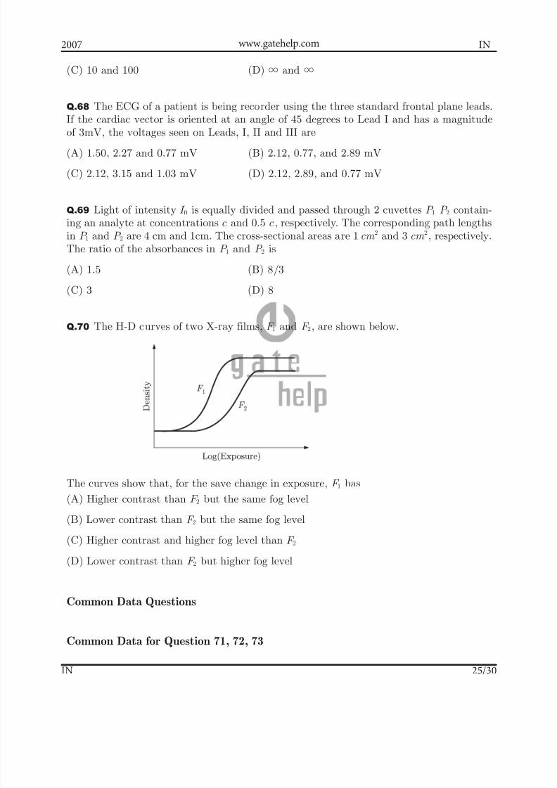
Q.70 The H-D curves of two X-ray films, F 1 and F 2, are shown below.
The curves show that, for the save change in exposure, F 1 has(A) Higher contrast than F 2 but the same fog level
(B) Lower contrast than F 2 but the same fog level
(C) Higher contrast and higher fog level than F 2
(D) Lower contrast than F 2 but higher fog level
Common Data Questions
Common Data for Question 71, 72, 73

7/27/2019 GATE- IN 2007
http://slidepdf.com/reader/full/gate-in-2007 26/30
2007 IN
IN 26/30
www.gatehelp.com
Consider the op-amp circuit shown in the figure below.
Q.71 If V 0.2 V, V 0.6 V and V 7 V1 2 0= = =− , and the op-amp is ideal, the value of R1 is
(A) 5 kΩ (B) 10 kΩ
(C) 15 k Ω (D) 20 k Ω
Q.72 Let V V V sin2 and R 20 k ft 1 2 c 1π Ω= = = . The op-amp has a slew rate of 0.5 V/ sμ with its other parameter being idea. The values of V c and f for which the amplifier outputwill have not distortion are, respectively
(A) 0.1 V and 300 kHz (B) 0.5 V and 300 kHz
(C) 0.1 V and 300 kHz (D) 0.5 V and 30 kHz
Q.73 Let V V 0 and R 20 k1 2 1 Ω= = = . Assume that the op-amp is ideal except for a non-zero input bias current. What is the value of R2 for the output voltage of the op-amp tobe zero ?
(A) 2.2 kΩ (B) 9.1 kΩ
(C) 20 k Ω (D) 100 k Ω
Common Data for Question 74, 75
The following figure represents a proportional control scheme of a first order system with
transportation lag.

7/27/2019 GATE- IN 2007
http://slidepdf.com/reader/full/gate-in-2007 27/30
2007 IN
IN 27/30
www.gatehelp.com
Q.74 The angular frequency in radians/ s at which the loop phase lag becomes 180c is
(A) 0.408 (B) 0.818
(C) 1.56 (D) 2.03
Q.75 The steady state error for a unit step input when the gain K 1C = is
(A) 41 (B) 2
1
(C) 1 (D) 2
Linked Answer Questions : Q.76 to Q.85 carry two marks each.
Statement for Linked Answer Questions 76 and 77 :Blood flow through a straight segment of an artery is measured using Doppler flowmeter.The probe is oriented at an angle of 45 degrees to the longitudinal axis of the artery. Itis known the Doppler shift is proportional to the velocity of the blood in the directionof propagation of sound from the probe and the frequency generated from the probe.The velocity of sound in blood is 1500 m/s and the maximum blood flow velocity to themeasured is 110 cm/s.
Q.76 Signal processing limitations constrain the maximum Doppler shift to be less than 3kHz. The maximum source frequency (probe output), to the nearest MHz, should be
(A) 2 MHz (B) 3 MHz
(C) 5 MHz (D) 10 MHz
Q.77 In Q. 76, if the piezoelectric crystal of the probe is made of quartz (Young’s modu-lus, Y 80 10 N.m , 2.65 10 kg.m9 2 3 3# #ρ= =− − ), the maximum thickness of the crystal re-quired to resonate at the frequency determined above, to the nearest mm, is
(A) 1 mm (B) 2 mm
(C) 3 mm (D) 4 mm
Statement for Linked Answer Questions 78 and 79:
Consider the circuit shown in the following figure.

7/27/2019 GATE- IN 2007
http://slidepdf.com/reader/full/gate-in-2007 28/30
2007 IN
IN 28/30
www.gatehelp.com
Q.78 The correct input-output relationship between Y and ( , )X X 1 2
is
(A) Y X X 1 2= + (B) Y X X 1 2=
(C) Y X X 1 25= (D) Y X X 1 25=
Q.79 The D flip-flop are initialized to .Q Q Q 0001 2 3 = After 1 clock cycle,
Q Q Q 1 2 3 is equal to(A) 011 (B) 010
(C) 100 (D) 101
Statement for Linked Answer Questions 80 and 81 :
The numerical aperture of a step index fiber in air (refractive index =1), is 0.39. Thediameter of the core is 200 mμ .
Q.80 The angle of acceptance when the fibre is used in water (refractive index =1.33) isclosest to
(A) 15c (B) 16c
(C) 17 c (D) 18 c
Q.81 Two experiments are conducted in which light in launched into the fiber from a uni-formly distributed planar source kept 5mm away from the tip. In the first experiment ( )E 1 both the source and the fiber are in air. In the second experiment ( ) E 2 both the sourceand the fiber are in water. Neglecting absorption in the medium between the source and

7/27/2019 GATE- IN 2007
http://slidepdf.com/reader/full/gate-in-2007 29/30
2007 IN
IN 29/30
www.gatehelp.com
the tip, the ratio of the amount of light coupled into fiber in ( )E 1 to the amount of lightcoupled into the fiber in E 2 is closest to
(A) 0.5 (B) 1.0
(C) 1.4 (D) 1.9
Statement for Linked Answer Questions 82 and 83
A push-pull capacitive displacement transducer is interfaced to a differential amplifier andan ADC as shown in the figure below.
Note that the bridge supply and the analog reference input for the ADC are derived fromthe same 10 V DC source.
Q.82 The change in capacitance for full scale displacement is %5! for the capacitors.The gain of the differential amplifier for utilization of the full range of the ADC (Whichis 10V! ) is
(A) 10 (B) 20(C) 30 (D) 40
Q.83 If the supply voltage to the bridge decreases by %,5 the sensitivity of the measure-ment system
(A) Decreases by 5% (B) Does not change
(C) Increase by 5% (D) Increases by 200%
Statement for Linked Answer Questions 84 and 85 :
A transfer function with unity DC gain has three poles at 1, 2, 3and− − − and no finitezeros. A plant with this transfer function is connected with a proportional controller of gain K in the forward path, in a unity feedback configuration.
Q.84 The transfer function is

7/27/2019 GATE- IN 2007
http://slidepdf.com/reader/full/gate-in-2007 30/30
2007 INwww.gatehelp.com
(A) ( ) ( ) ( )s s s s
1 2 3− − − (B) (s 1)(s 2)(s 3)6
+ + +
(C) (s 1) (s 2) (s 3)s
+ + + (D) (s 1)(s 2)(s 3)6
− − −
Q.85 If the locus plot of the closed loop system passes through the points j 11! , themaximum value of K for stability of the unity feedback closed loop system is
(A) 11 (B) 6
(C) 10 (D) 6 11
**********