GATE EE - 2003 · ones with fixed shunt capacitors. All the other buses are load buses. It is...
24
GATE EE - 2003 www.gateforum.com Join discussion of this test paper at http://forum.gatementor.com Join All India Mock GATE Classroom Test Series - 2007 conducted by GATE Forum in over 25 cities all over India. Question Papers including section tests and full tests are designed by IISc alumni according to the latest syllabus. Percentile, All India Rank, interaction with IISc alumni in our online discussion forums, and more. For more details, visit www.gateforum.com Think GATE Think GATE Forum Q.1 – Q.30 CARRY ONE MARK EACH 1. Fig.Q1 shows the waveform of the current passing through an inductor of resistance 1Ω and inductance 2 H. The energy absorbed by the inductor in the first four seconds is (a) 144 J (b) 98 J (c) 132 J (d) 168 J 2. A segment of a circuit is shown in Fig.Q2. V R = 5V, V C = 4 sin 2t. The voltage V L is given by (a) 3 – 8 cos 2t (b) 32 sin 2t (c) 16 sin 2t (d) 16 cos 2t 3. In the Fig.Q3. Z 1 =10∠-60°, A2=10∠60°, Z 3 =50∠53.13°. The Venn impedance seen from X-Y is (a) 56.6∠45° (b) 60∠30° (c) 70∠30° (d) 34.4∠65° 4. Two conductors are carrying forward and return current of +I and –I as shown in Fig.Q4. The magnetic field intensity H at point P is (a) I y d π (b) I x d π (c) 2 I y d π (d) 2 I x d π 0 2S 6A 4S t + - - - + + VR 2A 5Ω 1F VL VC 2H P R S Q ~ Z1 Z3 Z2 X Y + - 100∠0° z ur x ur y ur P -I +I d d
Transcript of GATE EE - 2003 · ones with fixed shunt capacitors. All the other buses are load buses. It is...
GATE EE - 2003 www.gateforum.com
Join discussion of this test paper at http://forum.gatementor.com
Join All India Mock GATE Classroom Test Series - 2007 conducted by GATE Forum in over 25 cities all over India. Question
Papers including section tests and full tests are designed by IISc alumni according to the latest syllabus. Percentile, All India Rank, interaction with IISc alumni in our online discussion forums, and more. For more details,
visit
www.gateforum.com
Think GATE Think GATE Forum
Q.1 – Q.30 CARRY ONE MARK EACH
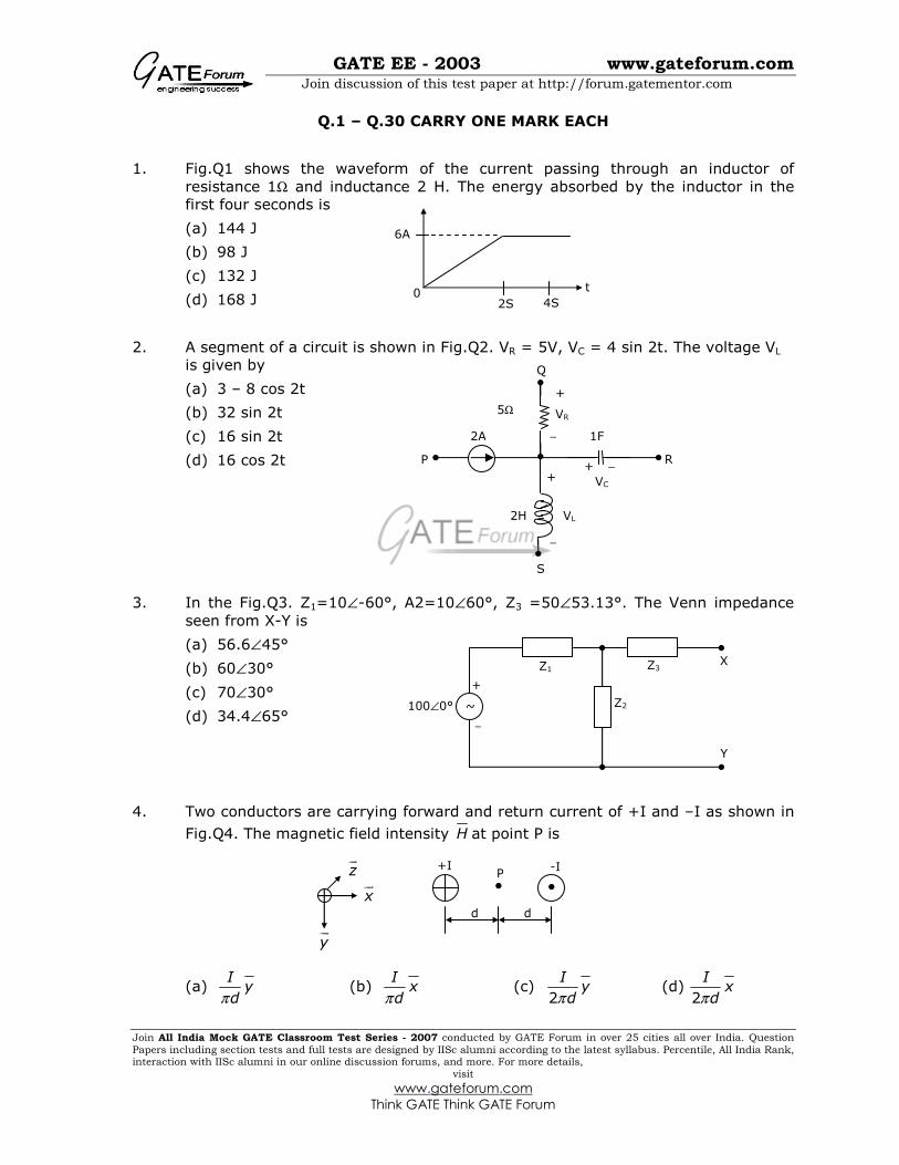
1. Fig.Q1 shows the waveform of the current passing through an inductor of
resistance 1Ω and inductance 2 H. The energy absorbed by the inductor in the
first four seconds is
(a) 144 J
(b) 98 J
(c) 132 J
(d) 168 J
2. A segment of a circuit is shown in Fig.Q2. VR = 5V, VC = 4 sin 2t. The voltage VL
is given by
(a) 3 – 8 cos 2t
(b) 32 sin 2t
(c) 16 sin 2t
(d) 16 cos 2t
3. In the Fig.Q3. Z1=10∠-60°, A2=10∠60°, Z3 =50∠53.13°. The Venn impedance
seen from X-Y is
(a) 56.6∠45°
(b) 60∠30°
(c) 70∠30°
(d) 34.4∠65°
4. Two conductors are carrying forward and return current of +I and –I as shown in
Fig.Q4. The magnetic field intensity H at point P is
(a) Iy
dπ (b)
Ix
dπ (c)
2
Iy
dπ (d)
2
Ix
dπ
0 2S
6A
4S
t
+
−
−
− + +
VR
2A
5Ω
1F
VL
VC
2H
P R
S
Q
~
Z1 Z3
Z2
X
Y
+
−
100∠0°
zur
xur
yur
P -I +I
d d

GATE EE - 2003 www.gateforum.com
Join discussion of this test paper at http://forum.gatementor.com
Join All India Mock GATE Classroom Test Series - 2007 conducted by GATE Forum in over 25 cities all over India. Question
Papers including section tests and full tests are designed by IISc alumni according to the latest syllabus. Percentile, All India Rank, interaction with IISc alumni in our online discussion forums, and more. For more details,
visit
www.gateforum.com
Think GATE Think GATE Forum
5. Two infinite strips of width w m in x direction as shown in Fig.Q5, are carrying
forward and return currents of +I and –I in the z direction. The strips are
separated by a distance of xm. The inductance per unit length of the
configuration is measured to be L H/m. If the distance of separation between the
strips is now reduced to ,2
xm the inductance per unit length of the configuration
is
(a) 2L H/m
(b) L/4 H/m
(c) L/2 H/m
(d) 4L H/m
6. A single phase transformer has a maximum efficiency of 90% at full load and
unity power factor. Efficiency at half load at the same power factor is
(a) 86.7% (b) 88.26% (c) 88.9% (d) 87.8%
7. Group I lists different applications and Group II lists the motors for these
applications. Match the application with the most suitable motor and choose the right combination among the choices given thereafter
Group I Group II
P Food mixer 1 Permanent magnet dc motor
Q Cassette tape recorder 2 Single phase induction motor
R Domestic water pump 3 Universal motor
S Escalator 4 Three phase induction motor
5 DC series motor
6 Stepper motor
(a) P – 3 Q – 6 R – 4 S - 5 (b) P – 1 Q – 3 R – 2 S - 4
(c) P – 3 Q – 1 R – 2 S - 4 (d) P – 3 Q – 2 R – 1 S - 4
8. A stand-alone engine driven Synchronous generator is feeding a partly inductive
load. A capacitor is now connected across the load to completely nullify the inductive current. For this operating condition.
(a) the field current and fuel input have to be reduced
(b) the field current and fuel input have to be increased
(c) the field current has to be increased and fuel input left unaltered
(d) the field current has to be reduced and fuel input left unaltered
zur
xur
yur
+I
-I
w
x

GATE EE - 2003 www.gateforum.com
Join discussion of this test paper at http://forum.gatementor.com
Join All India Mock GATE Classroom Test Series - 2007 conducted by GATE Forum in over 25 cities all over India. Question
Papers including section tests and full tests are designed by IISc alumni according to the latest syllabus. Percentile, All India Rank, interaction with IISc alumni in our online discussion forums, and more. For more details,
visit
www.gateforum.com
Think GATE Think GATE Forum
9. Curves X and Y in Fig.Q9 denote open circuit and full-load zero power factor (zpf)
characteristics of asynchronous generator. Q is a point on the zpf characteristics
at 1.0 p.u. voltage. The vertical distance PQ in Fig.Q.9 gives the voltage drop across
(a) Synchronous reactance
(b) Magnetizing reactance
(c) Potier reactance
(d) Leakage reactance
10. No-load test on a 3-phase induction motor was conducted at different supply
voltages and a plot of input power versus voltage was drawn. This curve was extrapolated to intersect the y-axis. This intersection point yields
(a) Core loss (b) Stator copper loss
(c) Stray load loss (d) Friction and windage loss
11. Bundled conductors are mainly used in high voltage overhead transmission lines
to
(a) reduce transmission line losses
(b) increase mechanical strength of the line
(c) reduce corona (d) reduce sag
12. A power system consists of 300 buses out of which 20 buses are generator
buses, 25 buses are the ones with reactive power support and 15 buses are the
ones with fixed shunt capacitors. All the other buses are load buses. It is
proposed to perform a load flow analysis for the system using Newton-Raphson method. The size of the Newton-Raphson Jacobian matrix is
(a) 553×553 (b) 540×540 (c) 555×555 (d) 554×554
13. Choose two appropriate auxiliary components of a HVDC transmission system
from the following
P D.C. line inductor
Q A.C. line inductor
R Reactive power sources
S Distance relays on D.C. line
T Series capacitance of A.C. line
(a) P and Q (b) P and R (c) Q and S (d) S and T
P
Q
X
Y
1.0
Voltage (p.u)
Field Current

GATE EE - 2003 www.gateforum.com
Join discussion of this test paper at http://forum.gatementor.com
Join All India Mock GATE Classroom Test Series - 2007 conducted by GATE Forum in over 25 cities all over India. Question
Papers including section tests and full tests are designed by IISc alumni according to the latest syllabus. Percentile, All India Rank, interaction with IISc alumni in our online discussion forums, and more. For more details,
visit
www.gateforum.com
Think GATE Think GATE Forum
14. A round rotor generator with internal voltage E1 = 2.0 p.u. and X = 1.1 p.u. is
connected to a round rotor synchronous motor with internal voltage E2 = 1.3 p.u.
and X = 1.2 p.u. The reactance of the line connecting the generator to the motor
is 0.5 p.u. when the generator supplies 0.5 p.u. power, the rotor angle difference between the machines will be
(a) 57.42° (b) 1° (c) 32.58° (d) 122.58°
15. The interrupting time of a circuit breaker is the period between the instant of
(a) initiation of short circuit and the arc extinction on an opening operation
(b) energizing of the trip circuit and the arc extinction on an opening operation
(c) initiation of short circuit and the parting of primary arc contacts
(d) energizing of the trip circuit and the parting of primary arc contacts
16. The variation of drain current with gate-to-source voltage
( ) characteristicD GSI V− of a MOSFET is shown in Fig.Q.16. The MOSFET is
(a) an n-channel depletion mode device
(b) an n-channel enhancement mode device
(c) a p-channel depletion mode device
(d) a p-channel enhancement mode device
17. In the circuit of Fig.Q17, assume that the transistor has 99 and 0.7 .FE BEh V V= = The value of collector current IC of the transistor is
approximately
(a) [3.3/3.3] mA
(b) [3.3/(3.3+.33] mA
(c) [3.3/33] mA
(d) [3.3/(33+3.3] mA
18. For the circuit of Fig.Q18 with an ideal operational amplifier, the maximum phase
shift of the output Vout with reference to the input Vin is
(a) 0° (b) -90° (c) +90° (d) ±180°
ID
VGS 0
3.3kΩ
33kΩ
4V 3.3kΩ
12V
IC
+
−
R
C
R1
R1
vout Vin

GATE EE - 2003 www.gateforum.com
Join discussion of this test paper at http://forum.gatementor.com
Join All India Mock GATE Classroom Test Series - 2007 conducted by GATE Forum in over 25 cities all over India. Question
Papers including section tests and full tests are designed by IISc alumni according to the latest syllabus. Percentile, All India Rank, interaction with IISc alumni in our online discussion forums, and more. For more details,
visit
www.gateforum.com
Think GATE Think GATE Forum
19. Fig.Q19 shows a 4 to 1 MUX to be used to implement the sum S of a 1-bit full
adder with input bits P and Q and the carry input Cin. Which of the following
combinations of inputs to I0, I1, I2 and I3 of the MUX will realize the sum S?
(a) 0 1 2 3;in inI I C I I C= = = =
(b) 0 1 2 3;in inI I C I I C= = = =
(c) 0 3 1 2;in inI I C I I C= = = =
(d) 0 3 1 2;in inI I C I I C= = = =
20. When a program is being executed in an 8085 microprocessor, its Program
Counter contains
(a) the number of instructions in the current program that have already been
executed
(b) the total number of instructions in the program being executed
(c) the memory address of the instruction that is being currently executed
(d) the memory address of the instruction that is to be executed next
21. A control system is defined by the following mathematical relationship
( )2
2
26 5 12 1 td x dx
x edtdt
−+ + = −
The response of the system as t ∞ is
(a) x = 6 (b) x = 2 (c) x = 2.4 (d) x = -2
22. A lead compensator used for a closed loop controller has the following transfer
function
1
1
sK
a
s
b
+
+
.
For such a lead compensator
(a) a < b (b) b < a (c) a > Kb (d) a < Kb
23. A second order system starts with an initial condition of 2
3
without any external
input. The state transition matrix for the system is given by 2 0
.0
t
t
e
e
−
−
The
state of the system at the end of 1 second is given by
(a) 0.271
1.100
(b) 0.135
0.368
(c) 0.271
0.736
(d) 0.135
1.100
P Q
I0
F
S1
S
4 to 1 MUX
I1
I3
I2
S0
GATE EE - 2003 www.gateforum.com
Join discussion of this test paper at http://forum.gatementor.com
Join All India Mock GATE Classroom Test Series - 2007 conducted by GATE Forum in over 25 cities all over India. Question
Papers including section tests and full tests are designed by IISc alumni according to the latest syllabus. Percentile, All India Rank, interaction with IISc alumni in our online discussion forums, and more. For more details,
visit
www.gateforum.com
Think GATE Think GATE Forum
24. A Manganin swamp resistance is connected in series with a moving coil ammeter
consisting of a milli-ammeter and a suitable shunt in order to
(a) minimize the effect of temperature variation
(b) obtain large deflecting torque
(c) reduce the size of the meter
(d) minimize the effect of stray magnetic fields
25. The effect of stray magnetic fields on the actuating torque of a portable
instrument is maximum when the operating field of the instrument and the stray fields are
(a) perpendicular (b) parallel
(c) inclined at 60° (d) inclined at 30°
26. A reading of 120 is obtained when a standard inductor was connected in the
circuit of a Q-meter and the variable capacitor is adjusted to a value of 300 pF. A
lossless capacitor of unknown value Cx is then connected in parallel with the
variable capacitor and the same reading was obtained when the variable capacitor is readjusted to a value of 200 pF. The value of Cx in pF is
(a) 100 (b) 200 (c) 300 (d) 500
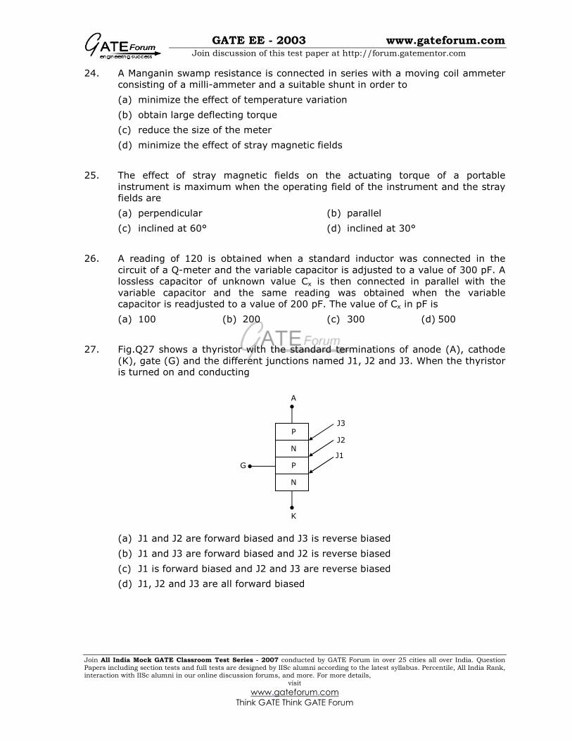
27. Fig.Q27 shows a thyristor with the standard terminations of anode (A), cathode
(K), gate (G) and the different junctions named J1, J2 and J3. When the thyristor is turned on and conducting
(a) J1 and J2 are forward biased and J3 is reverse biased
(b) J1 and J3 are forward biased and J2 is reverse biased
(c) J1 is forward biased and J2 and J3 are reverse biased
(d) J1, J2 and J3 are all forward biased
A
G
K
N
P
N
P
J1
J2
J3

GATE EE - 2003 www.gateforum.com
Join discussion of this test paper at http://forum.gatementor.com
Join All India Mock GATE Classroom Test Series - 2007 conducted by GATE Forum in over 25 cities all over India. Question
Papers including section tests and full tests are designed by IISc alumni according to the latest syllabus. Percentile, All India Rank, interaction with IISc alumni in our online discussion forums, and more. For more details,
visit
www.gateforum.com
Think GATE Think GATE Forum
28. Fig.Q28 shown a MOSFET with an integral body diode. It is employed as a power
switching device in the ON and OFF states through appropriate control. The ON
and OFF states of the switch are given on the VDS-IS plane by
(a) Fig.A (b) Fig.B (c) Fig.C (d) Fig.D
29. The speed/torque regimes in a dc motor and the control methods suitable for the same are given respectively in Group II and Group I
Group I Group II
P Field Control 1 Below base speed
Q Armature Control 2 Above base speed
3 Above base torque
4 Below base torque
(a) P – 1; Q - 3 (b) P – 2; Q - 1 (c) P – 2; Q - 3 (d) P – 1; Q - 4
D
G
S
IS
VDS
× ×
IS ×
VDS
Fig.A
×
×
IS ×
VDS
Fig.B
×
×
IS ×
VDS
Fig.C
× ×
IS
×
VDS
Fig.D
GATE EE - 2003 www.gateforum.com
Join discussion of this test paper at http://forum.gatementor.com
Join All India Mock GATE Classroom Test Series - 2007 conducted by GATE Forum in over 25 cities all over India. Question
Papers including section tests and full tests are designed by IISc alumni according to the latest syllabus. Percentile, All India Rank, interaction with IISc alumni in our online discussion forums, and more. For more details,
visit
www.gateforum.com
Think GATE Think GATE Forum
30. A fully controlled natural commuted 3-phase bridge rectifier is operating with a
firing angle α=30°. The peak to peak voltage ripple expressed as a ratio of the
peak output dc voltage at the output of the converter bridge is
(a) 0.5 (b) 3
2 (c)
31
2
−
(d) 3 1−
Q.31 – Q.90 CARRY TWO MARKS EACH
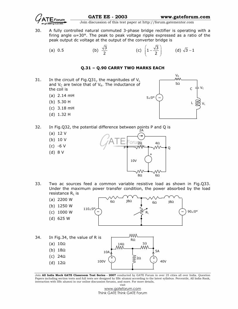
31. In the circuit of Fig.Q31, the magnitudes of VL
and VC are twice that of VK. The inductance of
the coil is
(a) 2.14 mH
(b) 5.30 H
(c) 3.18 mH
(d) 1.32 H
32. In Fig.Q32, the potential difference between points P and Q is
(a) 12 V
(b) 10 V
(c) -6 V
(d) 8 V
33. Two ac sources feed a common variable resistive load as shown in Fig.Q33.
Under the maximum power transfer condition, the power absorbed by the load resistance RL is
(a) 2200 W
(b) 1250 W
(c) 1000 W
(d) 625 W
34. In Fig.34, the value of R is
(a) 10Ω
(b) 18Ω
(c) 24Ω
(d) 12Ω
L
VC
VL
VR
5Ω
5∠0°
C
~
2A
2Ω 4Ω
10V
8Ω 6Ω
Q P
+
~ ~
6Ω j8Ω 6Ω j8Ω
RL
110∠0° 90∠0°
14Ω 1Ω
40V 2Ω
100V
10A
RΩ
+ -
5A
+ -
GATE EE - 2003 www.gateforum.com
Join discussion of this test paper at http://forum.gatementor.com
Join All India Mock GATE Classroom Test Series - 2007 conducted by GATE Forum in over 25 cities all over India. Question
Papers including section tests and full tests are designed by IISc alumni according to the latest syllabus. Percentile, All India Rank, interaction with IISc alumni in our online discussion forums, and more. For more details,
visit
www.gateforum.com
Think GATE Think GATE Forum
35. A balanced delta connected load of (8+j6) Ω per phase is connected to a 400 V,
50 Hz, 3-phase supply lines. If the input power factor is to be improved to 0.9 by connecting a bank of star connected capacitors the required kVAR of the bank is
(a) 42.7 (b) 10.2 (c) 28.8 (d) 38.4
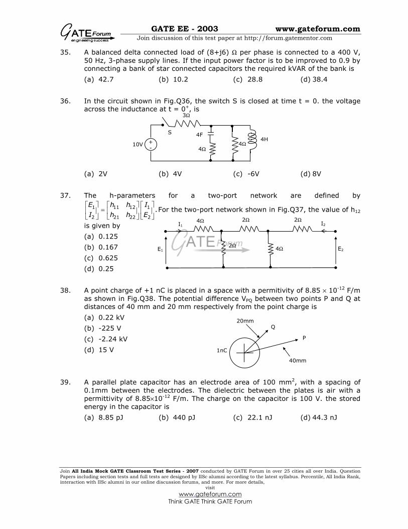
36. In the circuit shown in Fig.Q36, the switch S is closed at time t = 0. the voltage across the inductance at t = 0+, is
(a) 2V (b) 4V (c) -6V (d) 8V
37. The h-parameters for a two-port network are defined by
1 11 12 1
2 21 22 2
.E h h I
I h h E
=
For the two-port network shown in Fig.Q37, the value of h12
is given by
(a) 0.125
(b) 0.167
(c) 0.625
(d) 0.25
38. A point charge of +1 nC is placed in a space with a permitivity of 8.85 × 10⁻¹² F/m
as shown in Fig.Q38. The potential difference VPQ between two points P and Q at
distances of 40 mm and 20 mm respectively from the point charge is
(a) 0.22 kV
(b) -225 V
(c) -2.24 kV
(d) 15 V
39. A parallel plate capacitor has an electrode area of 100 mm2, with a spacing of
0.1mm between the electrodes. The dielectric between the plates is air with a
permittivity of 8.85×10⁻¹² F/m. The charge on the capacitor is 100 V. the stored
energy in the capacitor is
(a) 8.85 pJ (b) 440 pJ (c) 22.1 nJ (d) 44.3 nJ
3Ω
10V 4Ω
+ -
4Ω
4F 4H
S
2Ω 4Ω
4Ω
2Ω
2Ω E1 E2
I2 I1
P
Q
1nC
20mm
40mm
GATE EE - 2003 www.gateforum.com
Join discussion of this test paper at http://forum.gatementor.com
Join All India Mock GATE Classroom Test Series - 2007 conducted by GATE Forum in over 25 cities all over India. Question
Papers including section tests and full tests are designed by IISc alumni according to the latest syllabus. Percentile, All India Rank, interaction with IISc alumni in our online discussion forums, and more. For more details,
visit
www.gateforum.com
Think GATE Think GATE Forum
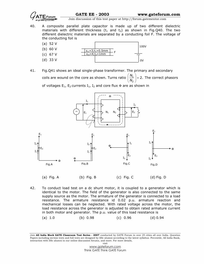
40. A composite parallel plate capacitor is made up of two different dielectric
materials with different thickness (t1 and t2) as shown in Fig.Q40. The two
different dielectric materials are separated by a conducting foil F. The voltage of the conducting foil is
(a) 52 V
(b) 60 V
(c) 67 V
(d) 33 V
41. Fig.Q41 shows an ideal single-phase transformer. The primary and secondary
coils are wound on the core as shown. Turns ratio 1
2
2.N
N
=
The correct phasors
of voltages E1, E2 currents I1, I2 and core flux Φ are as shown in
(a) Fig. A (b) Fig. B (c) Fig. C (d) Fig. D
42. To conduct load test on a dc shunt motor, it is coupled to a generator which is
identical to the motor. The field of the generator is also connected to the same
supply source as the motor. The armature of the generator is connected to a load
resistance. The armature resistance id 0.02 p.u. armature reaction and
mechanical losses can be neglected. With rated voltage across the motor, the
load resistance across the generator is adjusted to obtain rated armature current in both motor and generator. The p.u. value of this load resistance is
(a) 1.0 (b) 0.98 (c) 0.96 (d) 0.94
~
Φ
N1 N2 E1 E2
I1
I2
100V
0V
εr1=3;t1=0.5mm
εr2=4;t2=1mm F
Φ
E2
I1
I2
Fig.A
E1
Φ
E2
I1
I2
Fig.B
E1 E1
E2
I2
I1 Φ
Fig.C
E1
E2
I2
Φ
I1
Fig.D
GATE EE - 2003 www.gateforum.com
Join discussion of this test paper at http://forum.gatementor.com
Join All India Mock GATE Classroom Test Series - 2007 conducted by GATE Forum in over 25 cities all over India. Question
Papers including section tests and full tests are designed by IISc alumni according to the latest syllabus. Percentile, All India Rank, interaction with IISc alumni in our online discussion forums, and more. For more details,
visit
www.gateforum.com
Think GATE Think GATE Forum
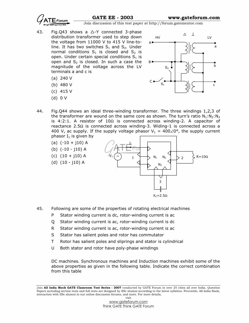
43. Fig.Q43 shows a -Y connected 3-phase
distribution transformer used to step down
the voltage from 11000 V to 415 V line-to-
line. It has two switches S1 and S2. Under
normal conditions S1 is closed and S2 is
open. Under certain special conditions S1 is
open and S2 is closed. In such a case the
magnitude of the voltage across the LV terminals a and c is
(a) 240 V
(b) 480 V
(c) 415 V
(d) 0 V
44. Fig.Q44 shows an ideal three-winding transformer. The three windings 1,2,3 of
the transformer are wound on the same core as shown. The turn’s ratio N1:N2:N3
is 4:2:1. A resistor of 10Ω is connected across winding-2. A capacitor of
reactance 2.5Ω is connected across winding-3. Widing-1 is connected across a
400 V, ac supply. If the supply voltage phasor V1 = 400∠0°, the supply current
phasor I1 is given by
(a) (-10 + j10) A
(b) (-10 - j10) A
(c) (10 + j10) A
(d) (10 - j10) A
45. Following are some of the properties of rotating electrical machines
P Stator winding current is dc, rotor-winding current is ac
Q Stator winding current is ac, rotor-winding current is dc
R Stator winding current is ac, rotor-winding current is ac
S Stator has salient poles and rotor has commutator
T Rotor has salient poles and sliprings and stator is cylindrical
U Both stator and rotor have poly-phase windings
DC machines. Synchronous machines and Induction machines exhibit some of the
above properties as given in the following table. Indicate the correct combination from this table
~ N1 N2 V1 R=10Ω
I1
1 2
3
N3
XC=2.5Ω
A
B
C
HV
S1
S2
a
b
c
LV

GATE EE - 2003 www.gateforum.com
Join discussion of this test paper at http://forum.gatementor.com
Join All India Mock GATE Classroom Test Series - 2007 conducted by GATE Forum in over 25 cities all over India. Question
Papers including section tests and full tests are designed by IISc alumni according to the latest syllabus. Percentile, All India Rank, interaction with IISc alumni in our online discussion forums, and more. For more details,
visit
www.gateforum.com
Think GATE Think GATE Forum
DC machines Synchronous machines Induction machines
(a) P.S Q.T R.U
(b) Q.U P.T R.S
(c) P.S R.U Q.T
(d) R.S Q.U P.T
46. When Stator and Rotor windings of a 2-pole rotating electrical machine are
excited, each would produce a sinusoidal mmf distribution in the air gap with
peak values Fs and Fr respectively. The rotor mmf lags stator mmf by a space
angle δ at any instant as shown in Fig.Q46. Thus, half of stator and rotor surfaces
will form one pole with the other half forming the second pole. Further, the direction of torque acting on the rotor can be clockwise or counter-clockwise.
The following Table gives four sets of statements as regards poles and torque.
Select the correct set corresponding to the mmf axes as shown in Fig.Q46.
Stator
Surface ABC forms
Stator Surface CDA
forms
Rotor
Surface cda forms
Rotor
Surface cda forms
Torque is
(a) North Pole South Pole North Pole South Pole Clockwise
(b) South Pole North Pole North Pole South Pole Counter
clockwise
(c) North Pole South Pole South Pole North Pole Counter clockwise
(d) South Pole North Pole South Pole North Pole Clockwise
47. A 4-pole, 3-phase, double layer winding is housed in a 36-slot stator for an ac
machine with 60° phase spread. Coil span is 7 slot pitches. Number of slots in which top and bottom layers belong to different phases is
(a) 24 (b) 18 (c) 12 (d) 0
+
A
B
C
D
a
b
c
d
δ
Fs
Fr
Stator
Air gap
Rotor
Stator mmf axis
Rotor mmf axis

GATE EE - 2003 www.gateforum.com
Join discussion of this test paper at http://forum.gatementor.com
Join All India Mock GATE Classroom Test Series - 2007 conducted by GATE Forum in over 25 cities all over India. Question
Papers including section tests and full tests are designed by IISc alumni according to the latest syllabus. Percentile, All India Rank, interaction with IISc alumni in our online discussion forums, and more. For more details,
visit
www.gateforum.com
Think GATE Think GATE Forum
48. A 3-phase Inductor Motor is driving a constant torque load at rated voltage and
frequency. If both voltage and frequency are halved, following statements relate
to the new condition if stator resistance, leakage reactance and core loss are ignored.
P The difference between synchronous speed and actual speed remains same
Q The air-gap flux remains same
R The stator current remains same
S The p.u. slip remains same
Among the above, correct statements are
(a) All (b) P, Q and R (c) Q, R and S (d) P and S
49. A single phase induction motor with only the main winding excited would exhibit
the following response at synchronous speed
(a) Rotor current is zero
(b) Rotor current is non-zero and is at slip frequency
(c) Forward and backward rotating fields are equal
(d) Forward rotating field is more than the backward rotating field
50. A dc series motor driving an electric train faces a constant power load. It is
running at rated speed and rated voltage. If the speed has to be brought down to 0.25 p.u. the supply voltage has to be approximately brought down to
(a) 0.75 p.u. (b) 0.5 p.u. (c) 0.25 p.u. (d) 0.125 p.u.
51. The ABCD parameters of a 3-phase overhead transmission line are A = D =0.9∠0
B = 200∠90°Ω and C = 0.95×10⁻³ ∠90°S. At no-load condition a shunt inductive
reactor is connected at the receiving end of the line to limit the receiving end
voltage to be equal to the sending end voltage. The ohmic value of the reactor is
(a) ∞ Ω (b) 2000 Ω (c) 105.26 Ω (d) 1052.6 Ω
52. A surge of 20 kV magnitude travels along a lossless cable towards its junction
with two identical lossless overhead transmission lines. The inductance and the
capacitance of the cable are 0.4 mH and 0.5 µF per km. The inductance and
capacitance of the overhead transmission lines are 1.5 mH and 0.015 µF per km. The magnitude of the voltage at the junction due to surge is
(a) 36.72 kV (b) 18.36 kV (c) 6.07 kV (d) 33.93 kV
GATE EE - 2003 www.gateforum.com
Join discussion of this test paper at http://forum.gatementor.com
Join All India Mock GATE Classroom Test Series - 2007 conducted by GATE Forum in over 25 cities all over India. Question
Papers including section tests and full tests are designed by IISc alumni according to the latest syllabus. Percentile, All India Rank, interaction with IISc alumni in our online discussion forums, and more. For more details,
visit
www.gateforum.com
Think GATE Think GATE Forum
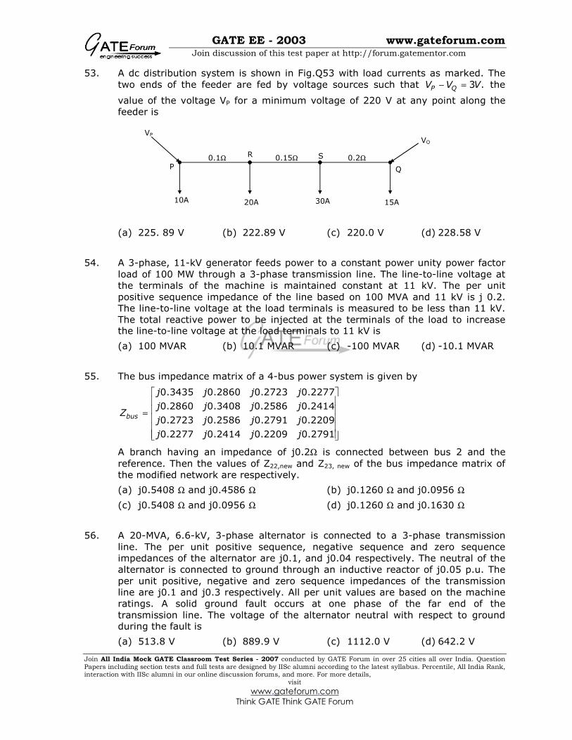
53. A dc distribution system is shown in Fig.Q53 with load currents as marked. The
two ends of the feeder are fed by voltage sources such that 3 .P QV V V− = the
value of the voltage VP for a minimum voltage of 220 V at any point along the
feeder is
(a) 225. 89 V (b) 222.89 V (c) 220.0 V (d) 228.58 V
54. A 3-phase, 11-kV generator feeds power to a constant power unity power factor
load of 100 MW through a 3-phase transmission line. The line-to-line voltage at
the terminals of the machine is maintained constant at 11 kV. The per unit
positive sequence impedance of the line based on 100 MVA and 11 kV is j 0.2.
The line-to-line voltage at the load terminals is measured to be less than 11 kV.
The total reactive power to be injected at the terminals of the load to increase the line-to-line voltage at the load terminals to 11 kV is
(a) 100 MVAR (b) 10.1 MVAR (c) -100 MVAR (d) -10.1 MVAR
55. The bus impedance matrix of a 4-bus power system is given by
0.3435 0.2860 0.2723 0.2277
0.2860 0.3408 0.2586 0.2414
0.2723 0.2586 0.2791 0.2209
0.2277 0.2414 0.2209 0.2791
bus
j j j j
j j j jZ
j j j j
j j j j
=
A branch having an impedance of j0.2Ω is connected between bus 2 and the
reference. Then the values of Z22,new and Z23, new of the bus impedance matrix of
the modified network are respectively.
(a) j0.5408 Ω and j0.4586 Ω (b) j0.1260 Ω and j0.0956 Ω
(c) j0.5408 Ω and j0.0956 Ω (d) j0.1260 Ω and j0.1630 Ω
56. A 20-MVA, 6.6-kV, 3-phase alternator is connected to a 3-phase transmission
line. The per unit positive sequence, negative sequence and zero sequence
impedances of the alternator are j0.1, and j0.04 respectively. The neutral of the
alternator is connected to ground through an inductive reactor of j0.05 p.u. The
per unit positive, negative and zero sequence impedances of the transmission
line are j0.1 and j0.3 respectively. All per unit values are based on the machine
ratings. A solid ground fault occurs at one phase of the far end of the
transmission line. The voltage of the alternator neutral with respect to ground during the fault is
(a) 513.8 V (b) 889.9 V (c) 1112.0 V (d) 642.2 V
P Q
VP
VQ
R S
10A 20A 30A 15A
0.1Ω 0.15Ω 0.2Ω

GATE EE - 2003 www.gateforum.com
Join discussion of this test paper at http://forum.gatementor.com
Join All India Mock GATE Classroom Test Series - 2007 conducted by GATE Forum in over 25 cities all over India. Question
Papers including section tests and full tests are designed by IISc alumni according to the latest syllabus. Percentile, All India Rank, interaction with IISc alumni in our online discussion forums, and more. For more details,
visit
www.gateforum.com
Think GATE Think GATE Forum
57. Incremental fuel costs (in some appropriate unit) for a power plant consisting of
three generating units are
1 1
2 2
3
20 0.3
30 0.4
30
IC P
IC P
IC
= +
= +
=
where P1 is the power in MW generated by unit i, for i = 1,2 and 3. Assume that
all the three units are operating all the time. Minimum and maximum loads on
each unit are 50 MW and 300 MW respectively. If the plant is operating on
economic load dispatch to supply the total power demand of 700 MW, the power generated by each unit is----------------
(a) P1 = 242.86 MW; P2= 157.14 MW; and P3 = 300 MW
(b) P1 = 157.14 MW; P2= 242.86 MW; and P3 = 300 MW
(c) P1 = 300.0 MW; P2= 300.0 MW; and P3 = 100 MW
(d) P1 = 233.3 MW; P2= 233.3 MW; and P3 = 233.4 MW
58. A list of relays and the power system components protected by the relays are
given in Group I and Group II respectively. Choose the correct match from the four choices given below:
Group I Group II
P Distance relay 1 Transformers
Q Under frequency relay 2 Turbines
R Differential relay 3 Busbars
S Buchholz relay 4 Shunt capacitors
5 Alternators
6 Transmission lines
(a) P – 6 Q – 5 R – 3 S - 1 (b) P – 4 Q – 3 R – 2 S - 1
(c) P – 5 Q – 2 R – 1 S - 6 (d) P – 6 Q – 4 R – 5 S - 3
59. A generator delivers power of 1.0 p.u. to an infinite bus through a purely reactive
network. The maximum power that could be delivered by the generator is 2.0
p.u. A three phase fault occurs at the terminals of the generator which reduces
the generator output to zero. The fault is cleared after tc second. The original
network is then restored. The maximum swing of the rotor angle is found to be
max 110δ = electrical degree. Then the rotor angle in electrical degrees at t = tc is
(a) 55 (b) 70 (c) 69.14 (d) 72.4

GATE EE - 2003 www.gateforum.com
Join discussion of this test paper at http://forum.gatementor.com
Join All India Mock GATE Classroom Test Series - 2007 conducted by GATE Forum in over 25 cities all over India. Question
Papers including section tests and full tests are designed by IISc alumni according to the latest syllabus. Percentile, All India Rank, interaction with IISc alumni in our online discussion forums, and more. For more details,
visit
www.gateforum.com
Think GATE Think GATE Forum
60. A three-phase alternator generating unbalanced voltages is connected to an
unbalanced load through a 3-phase transmission line as shown in Fig.Q60. the
neutral of the alternator and the star point of the load are solidly grounded. The phase voltages of the alternator are 10 0 , 10 90 , 10 120 .a b cE V E V E V= ∠ ° = ∠ − ° = ∠ °
The positive sequence component of the load current is
(a) 1.310∠-107°A (b) 0.332∠-120°A (c) 0.996∠-120°A (d) 3.510∠-81°A
61. For the n-channel enhancement MOSFET shown in Fig.Q61, the
threshold voltage Vtn = 2V. The drain current ID of the MOSFET is
4 mA when the drain resistance RD is 1 kΩ. If the value of RD is
increased to 4Ω, drain current ID will become
(a) 2.8 mA (b) 2.0 mA
(c) 1.4 mA (d) 1.0 mA
62. Assuming the operational amplifier to be ideal, the gain Vout/Vin for the circuit
shown in Fig.Q62 is
(a) -1 (b) -20 (c) -100 (d) -120
63. A voltage signal 10 sin ωt is applied to the circuit with ideal diodes, as shown in
Fig.Q63. The maximum, and minimum values of the output waveform Vout of the circuit are respectively 10 kwΩ
(a) + 10 V and – 10 V
(b) + 4 V and – 4 V
(c) + 7 V and – 4 V
(d) + 4 V and – 7 V
Ea
Eb
Ec
j1.0Ω
j1.0Ω
j1.0Ω
j1.0Ω
j2.0Ω
j3.0Ω
ID RD
10V
10kΩ
+
-
1kΩ
vout
vin
10kΩ
1kΩ
10kΩ
4V
+
vin
4V
10kΩ
-
vout
+
-

GATE EE - 2003 www.gateforum.com
Join discussion of this test paper at http://forum.gatementor.com
Join All India Mock GATE Classroom Test Series - 2007 conducted by GATE Forum in over 25 cities all over India. Question
Papers including section tests and full tests are designed by IISc alumni according to the latest syllabus. Percentile, All India Rank, interaction with IISc alumni in our online discussion forums, and more. For more details,
visit
www.gateforum.com
Think GATE Think GATE Forum
64. The circuit of Fig.Q64 shows a 555 Timer IC
connected as an astable multivibrator. The
value of the capacitor C is 10 nF. The values
of the resistors RA and RB for a frequency of
10 kHz and a duty cycle of 0.75 for the output voltage waveform are
(a) RA=3.62 kΩ, RB = 3.62 kΩ
(b) RA=3.62 kΩ, RB = 7.25 kΩ
(c) RA=7.25 kΩ, RB = 3.62 kΩ
(d) RA=7.25 kΩ, RB = 7.25 kΩ
65. The simplified block diagram of a 10-bit A/D converter of dual slope integrator
type is shown in Fig.Q65. The 10-bit counter at the output is clocked by a 1 MHz
clock. Assuming negligible timing overhead for the control logic, the maximum
frequency of the analog signal that can be converted using this A/D converter is
approximately
(a) 2 kHz (b) 1 kHz (c) 500 Hz (d) 250 Hz
66. The Boolean expression XYZ XYZ XYZ XYZ XYZ+ + + + can be simplified to
(a) XZ XZ YZ+ + (b) XZ YZ YZ+ +
(c) XY YZ XZ+ + (d) XY YZ XZ+ +
67. The shift register shown in Fig.Q67 is initially loaded with the bit pattern 1010.
Subsequently the shift register is clocked, and with each clock pulse the pattern
gets shifted by one bit position to the right. With each shift, the bit at the serial
input is pushed to the left most position (msb). After how many clock pulses will the content of the shift register become 1010 again?
(a) 3
(b) 7
(c) 11
(d) 15
RB
C
RA
Th
Tr R1
VCC
vout
Discharge
555 Timer IC
10-bit Counter
Integrator,
Comparator
and Control
Logic Clock
Digital
output
Reference dc input
Input sample to be converted
1 MHz
Serial input 1 0 0 1
Clock

GATE EE - 2003 www.gateforum.com
Join discussion of this test paper at http://forum.gatementor.com
Join All India Mock GATE Classroom Test Series - 2007 conducted by GATE Forum in over 25 cities all over India. Question
Papers including section tests and full tests are designed by IISc alumni according to the latest syllabus. Percentile, All India Rank, interaction with IISc alumni in our online discussion forums, and more. For more details,
visit
www.gateforum.com
Think GATE Think GATE Forum
68. An X-Y flip flop, whose Characteristic Table is given below is to be implemented
using a J-K flip flop
X Y 1nQ +
0 0 1
0 1 nQ
1 0 nQ
1 1 0
This can be done by making
(a) J = X, K = Y (b) J = ,X K = Y
(c) J = Y, K = X (d) J = Y , K = X
69. A memory system has a total of 8 memory chips, each with 12 address lines and
4 data lines. The total size of the memory system is
(a) 6 kbytes (b) 32 kbytes (c) 48 kbytes (d) 64 kbytes
70. The following program is written for an 8085 microprocessor to add two bytes
located at memory addresses 1FFE and 1FFF
LXI H, 1FFE
MOV B, M
INR L
MOV A, M
ADD B
INR L
MOV M, A
XOR A
On completion of the execution of the program, the result of addition is found
(a) in the register A (b) at the memory address 1000
(c) at the memory address 1F00 (d) at the memory address 2000

GATE EE - 2003 www.gateforum.com
Join discussion of this test paper at http://forum.gatementor.com
Join All India Mock GATE Classroom Test Series - 2007 conducted by GATE Forum in over 25 cities all over India. Question
Papers including section tests and full tests are designed by IISc alumni according to the latest syllabus. Percentile, All India Rank, interaction with IISc alumni in our online discussion forums, and more. For more details,
visit
www.gateforum.com
Think GATE Think GATE Forum
71. A control system with certain excitation is governed by the following
mathematical equation
2
4 5
2
1 110 5 2
2 18
t td x dxx e e
dtdt
− −+ + = + +
The natural time constants of the response of the system are
(a) 2s and 5s (b) 3s and 6s (c) 4s and 5s (d) 1/3s and 1/6s
72. The block diagram shown in Fig.Q72-73 gives a unity feedback closed loop
control system. The steady state error in the response of the above system to
unit step input is
(a) 25%
(b) 0.75%
(c) 6%
(d) 33%
73. The roots of the closed loop characteristic equation of the system shown in Fig.Q72-73 are
(a) -1 and -15 (b) 6 and 10 (c) -4 and -15 (d) -6 and 10
74. The following equation defines a separately excited dc motor in the form of a
differential equation
2 2
2 a
d B d K KV
J dt LJ LJdt
ω ωω+ + =
The above equation may be organized in the state-space form as follows
2
2
a
dd
dt P QVdtd
dt
ωω
ω ω
= +
where the P matrix is given by
(a)
2
1 0
B K
J LJ
− −
(b)
2
0 1
K B
LJ J
− −
(c) 2
0 1
K B
LJ J
− −
(d) 2
1 0
B K
J LJ
− −
y(t) u(t) 3
15s +
15
1s +
-
+

GATE EE - 2003 www.gateforum.com
Join discussion of this test paper at http://forum.gatementor.com
Join All India Mock GATE Classroom Test Series - 2007 conducted by GATE Forum in over 25 cities all over India. Question
Papers including section tests and full tests are designed by IISc alumni according to the latest syllabus. Percentile, All India Rank, interaction with IISc alumni in our online discussion forums, and more. For more details,
visit
www.gateforum.com
Think GATE Think GATE Forum
75. The loop gain GH of a closed system is given by the following expression
( ) ( )2 4
K
s s s+ +
The value of K for which the system just becomes unstable is
(a) K = 6 (b) K = 8 (c) K = 48 (d) K = 96
76. The asymptotic Bode plot of the transfer function
1
K
s
a+
is given in Fig.Q76. The
error in phase angle and dB gain at a frequency of ω=0.5 a are respectively.
(a) 4.9°, 0.97 dB (b) 5.7°, 3 dB (c) 4.9°, 3 dB (d) 5.7°, 0.97 dB
77. The block diagram of a control system is shown in Fig.Q77. The transfer function
G(s) = Y(s)/U(s) of the system is
(a) 1
18 1 112 3
s s + +
(b) 1
27 1 16 9
s s + +
(c) 1
27 1 112 9
s s + +
(d) 1
27 1 19 3
s s + +
G dB
a ω
20db/decade
20 log K
Ph°
ω
45°/decade
0.1a 10a
Integrator
3
u(t) y(t) +
Integrator
9
12
2
−
+
−
−
GATE EE - 2003 www.gateforum.com
Join discussion of this test paper at http://forum.gatementor.com
Join All India Mock GATE Classroom Test Series - 2007 conducted by GATE Forum in over 25 cities all over India. Question
Papers including section tests and full tests are designed by IISc alumni according to the latest syllabus. Percentile, All India Rank, interaction with IISc alumni in our online discussion forums, and more. For more details,
visit
www.gateforum.com
Think GATE Think GATE Forum
78. The items in Group I represent the various types of measurements to be made
with a reasonable accuracy using a suitable bridge. The items in Group II
represent the various bridges available for this purpose. Select the correct choice of the item in Group II for the corresponding item in Group I from the following
Group I Group II
P Resistance in the milli-Ohm range 1 Wheatstone Bridge
Q Low values of Capacitance 2 Kelvin Double Bridge
R Comparison of resistances which are nearly equal 3 Schering Bridge
S Inductance of a coil with a large time constant 4 Wien’s Bridge
5 Hay’s Bridge
6 Carey-Foster Bridge
(a) P – 2 Q – 3 R – 6 S - 5 (b) P – 2 Q – 6 R – 4 S - 5
(c) P – 2 Q – 3 R – 5 S – 4 (d) P – 1 Q – 3 R – 2 S - 6
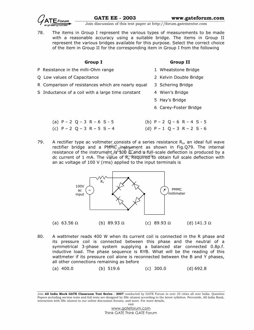
79. A rectifier type ac voltmeter consists of a series resistance Rs, an ideal full wave
rectifier bridge and a PMMC instrument as shown in Fig.Q79. The internal
resistance of the instrument is 100 Ω and a full-scale deflection is produced by a
dc current of 1 mA. The value of Rs Required to obtain full scale deflection with an ac voltage of 100 V (rms) applied to the input terminals is
(a) 63.56 Ω (b) 89.93 Ω (c) 89.93 Ω (d) 141.3 Ω
80. A wattmeter reads 400 W when its current coil is connected in the R phase and
its pressure coil is connected between this phase and the neutral of a
symmetrical 3-phase system supplying a balanced star connected 0.8p.f.
inductive load. The phase sequence is RYB. What will be the reading of this
wattmeter if its pressure coil alone is reconnected between the B and Y phases, all other connections remaining as before
(a) 400.0 (b) 519.6 (c) 300.0 (d) 692.8
Rs
~
100V ac
input
PMMC millimeter

GATE EE - 2003 www.gateforum.com
Join discussion of this test paper at http://forum.gatementor.com
Join All India Mock GATE Classroom Test Series - 2007 conducted by GATE Forum in over 25 cities all over India. Question
Papers including section tests and full tests are designed by IISc alumni according to the latest syllabus. Percentile, All India Rank, interaction with IISc alumni in our online discussion forums, and more. For more details,
visit
www.gateforum.com
Think GATE Think GATE Forum
81. The inductance of a certain moving-iron ammeter is expressed as 2
10 30 ,4
L Hθ
µ= + − where θ is the deflection in radians from the zero position.
The control spring torque in 25×10-6 Nm/radian. The deflection of the pointer in
radian when the meter carries a current of 5A, is
(a) 2.4 (b) 2.0 (c) 1.2 (d) 1.0
82. A 500 A/5 A, 50 Hz current transformer has a bar primary. The secondary burden
is a pure resistance of 1 Ω and it draws a current of 5 A. If the magnetic core
requires 250 AT for magnetization, the percentage ratio error is
(a) 10.56 (b) -10.56 (c) 11.80 (d) -11.80
83. The voltage flux adjustment of a certain 1-phase 220 V induction watt hour
meter is altered so that the phase angle between the applied voltage and the flux
due to it is 85° (instead of 90°). The errors introduced in the reading of this
meter when the current is 5A at power factors of unity and 0.5 lagging are respectively.
(a) 3.8 mW, 77.4 mW (b) -3.8 mW, -77.4 mW
(c) -4.2 W, -85.1 W (d) 4.2 W, 85.1 W
84. Group II represnts the figures obtained on a CRO screen when the voltage signals
Vx = Vxm sin ωt and Vy = Vym sin(ωt+Φ) are given to its X and Y plates
respectively and Φ is changed. Choose the correct value of Φ from Group I to
match with the corresponding figure of Group II
Group I Group II
P Φ = 0
Q Φ = π/2
R π < Φ < 3π/2
S Φ = 3π/2
(a) P – 1 Q – 3 R – 6 S - 5 (b) P – 2 Q – 6 R – 4 S - 5
(c) P – 2 Q – 3 R – 5 S – 4 (d) P – 1 Q – 5 R – 6 S - 5
1 2 3
4 5 6

GATE EE - 2003 www.gateforum.com
Join discussion of this test paper at http://forum.gatementor.com
Join All India Mock GATE Classroom Test Series - 2007 conducted by GATE Forum in over 25 cities all over India. Question
Papers including section tests and full tests are designed by IISc alumni according to the latest syllabus. Percentile, All India Rank, interaction with IISc alumni in our online discussion forums, and more. For more details,
visit
www.gateforum.com
Think GATE Think GATE Forum
85. In the circuit shown in Fig.Q85, the current gain (β) of the ideal transistor is 10.
The operating point of the transistor (Vcc, Ic) is
(a) (40V, 4A) (b) (40V, 5A) (c) (0V, 4A) (d) (15V, 4A)
86. A phase controlled half controlled single phase converter is shown in Fig.Q86. The
control angle α = 30°
The output dc voltage wave shape will be a s shown in
(a) Fig. A (b) Fig. B (c) Fig. C (d) Fig. D
0.5A
10Ω
IC
Vce 15V
40V
α=30° Idc
Vac
Vdc
Fig.A
Vdc
t
Vdc
t
Vdc
t
Fig.C
Vdc
t
Fig.D
Fig.B

GATE EE - 2003 www.gateforum.com
Join discussion of this test paper at http://forum.gatementor.com
Join All India Mock GATE Classroom Test Series - 2007 conducted by GATE Forum in over 25 cities all over India. Question
Papers including section tests and full tests are designed by IISc alumni according to the latest syllabus. Percentile, All India Rank, interaction with IISc alumni in our online discussion forums, and more. For more details,
visit
www.gateforum.com
Think GATE Think GATE Forum
87. A chopper is employed to charge a battery as shown in Fig.Q87. The charging
current is 5A. The duty ratio is 0.2. The chopper output voltage is also shown in
Fig.Q87. The peak to peak ripple current in the charging current is
(a) 0.48 A (b) 1.2 A (c) 2.4 A (d) 1 A
88. An inverter has a periodic output voltage with the output waveform as shown in
Fig.Q88-89. When the conduction angle α=120°, the rms fundamental
component of the output voltage is
(a) 0.78 V
(b) 1.10 V
(c) 0.90 V
(d) 1.27 V
89. With reference to the output waveform given in Fig.Q88-89, the output of the
converter will be free from 5th harmonic when
(a) α = 72° (b) α = 36° (c) α = 150° (d) α = 120°
90. An ac induction motor is used for a speed control application. It is driven from an
inverter with a constant V/f control. The motor nameplate details are as follows
V:415 V Ph:3 f:50Hz N:2850 rpm
The motor is run with the inverter output frequency set at 40 Hz, and with half
the rated slip. The running speed of the motor is
(a) 2400 rpm (b) 2280 rpm (c) 2340 rpm (d) 2790 rpm
5A
L=20mH
Vdc
Chopper 12V
200µS
1mS
t
Vdc 60V
α
0
1
π
2π
-1