(Gas/LPG) Sweeper Operator...
56
3640 *330580* www.tennantco.com Sweeper Operator Manual 330580 Rev. 06 (02-2008) North America / International (Gas/LPG)
Transcript of (Gas/LPG) Sweeper Operator...
3640
*330580*www.tennantco.com
SweeperOperator Manual
330580Rev. 06 (02-2008)
North America / International
(Gas/LPG)

This manual is furnished with each new model. It provides necessary operation and maintenance instructions.
Read this manual completely and understand the machine before operating or servicing it.
This machine will provide excellent service. However, the best results will be obtained at minimum costs if:
S The machine is operated with reasonable care.
S The machine is maintained regularly - per the machine maintenance instructions provided.
S The machine is maintained with manufacturer supplied or equivalent parts.
PROTECT THE ENVIRONMENTPlease dispose of packaging materials,old machine components such asbatteries, hazardous fluids includingantifreeze and oil, in an environmentallysafe way according to local wastedisposal regulations.
Always remember to recycle.
MACHINE DATAPlease fill out at time of installation for future reference.
Model No. --
Serial No. --
Machine Options --
Sales Rep. --
Sales Rep. phone no. --
Customer Number --
Installation Date --
Tennant CompanyPO Box 1452Minneapolis, MN 55440Phone: (800) 553--8033 or (763) 513--2850www.tennantco.com
CALIFORNIA PROPOSITION 65 WARNING:Engine exhaust from this product contains chemicals known to the State of California to cause cancer,birth defects, or other reproductive harm.
Specifications and parts are subject to change without notice.
Original instructions, Copyright E 2000, 2001, 2002, 2003, 2004, 2005, 2006, 2008 TENNANT Company, Printed in U.S.A.
CONTENTS
13640 330580 (12--00)
CONTENTS
PageSAFETY PRECAUTIONS 3. . . . . . . . . . . . . . . . .OPERATION 5. . . . . . . . . . . . . . . . . . . . . . . . . .
OPERATOR RESPONSIBILITY 5. . . . . . . . .MACHINE COMPONENTS 7. . . . . . . . . . . . .SYMBOL DEFINITIONS 8. . . . . . . . . . . . . . . .CONTROLS AND INSTRUMENTS 9. . . . . .OPERATION OF CONTROLS 10. . . . . . . . . .
DIRECTIONAL CONTROL LEVER 10. . .CLUTCH HANDLE 12. . . . . . . . . . . . . . . . . .MAIN BRUSH LEVER 12. . . . . . . . . . . . . . .SIDE BRUSH LEVER 13. . . . . . . . . . . . . . .ENGINE CHOKE KNOB 13. . . . . . . . . . . . .LOW OIL WARNING INDICATOR 13. . . .LOW BATTERY CHARGE
INDICATOR 14. . . . . . . . . . . . . . . . . . . . .STEERING BAR 14. . . . . . . . . . . . . . . . . . .STEERING BAR ADJUSTMENT
KNOBS 14. . . . . . . . . . . . . . . . . . . . . . . .IGNITION KEY SWITCH 15. . . . . . . . . . . .HOURMETER 15. . . . . . . . . . . . . . . . . . . . .VACUUM WAND 15. . . . . . . . . . . . . . . . . . .CIRCUIT BREAKER 16. . . . . . . . . . . . . . . .THERMO SENTRYt 16. . . . . . . . . . . . . . .FILTER SHAKER SWITCH 16. . . . . . . . . .
HOW THE MACHINE WORKS 17. . . . . . . . . .PRE-OPERATION CHECKLIST 17. . . . . . . . .
CHANGING AN LPG TANK 19. . . . . . . . . . . . . . . .STARTING THE MACHINE 21. . . . . . . . . . . . .SWEEPING AND BRUSH
INFORMATION 22. . . . . . . . . . . . . . . . . . . .SWEEPING 23. . . . . . . . . . . . . . . . . . . . . . . . . .STOP SWEEPING 24. . . . . . . . . . . . . . . . . . . .EMPTYING THE DEBRIS HOPPER 26. . . . .STANDARD HOPPER 26. . . . . . . . . . . . . . . . .HOPPER DUMP ASSIST
HANDLE (OPTION) 27. . . . . . . . . . . . . . . . .REPLACING THE BAG FILTER 28. . . . . . . . .CLEANING THE FILTER
COMPARTMENT 29. . . . . . . . . . . . . . . . . . .POST-OPERATION CHECKLIST 30. . . . . . . .OPERATION ON INCLINES 30. . . . . . . . . . . .OPTIONS 31. . . . . . . . . . . . . . . . . . . . . . . . . .
WIDE TRACK TIRES AND HEAVY DUTYCASTERS 31. . . . . . . . . . . . . . . . . . . . . .
MACHINE TROUBLESHOOTING 32. . . . . . .MAINTENANCE 33. . . . . . . . . . . . . . . . . . . . . . . . .
MAINTENANCE CHART 33. . . . . . . . . . . . . . .LUBRICATION 34. . . . . . . . . . . . . . . . . . . . . . . .
ENGINE 34. . . . . . . . . . . . . . . . . . . . . . . . . .HEAVY DUTY CASTERS (OPTION) 34. .
FUEL SYSTEM 35. . . . . . . . . . . . . . . . . . . . . . .FUEL FILTER AND SEDIMENT BOWL 35GAS VALVE 35. . . . . . . . . . . . . . . . . . . . . . .
ENGINE 36. . . . . . . . . . . . . . . . . . . . . . . . . .AIR FILTER 36. . . . . . . . . . . . . . . . . . . . . . . .SPARKPLUG 36. . . . . . . . . . . . . . . . . . . . . .
PageSKIRTS AND SEALS 37. . . . . . . . . . . . . . . . . .
MAIN BRUSH SKIRTS 37. . . . . . . . . . . . . .HOPPER DUST SEAL 37. . . . . . . . . . . . . .REAR SKIRT 37. . . . . . . . . . . . . . . . . . . . . .HOPPER LIP SKIRT 38. . . . . . . . . . . . . . . .FILTER COMPARTMENT
DOOR SEAL 38. . . . . . . . . . . . . . . . . . . .VACUUM INLET PLATE 38. . . . . . . . . . . . . . . .CLEANING THE PANEL FILTER 39. . . . . . . . .BRUSHES 40. . . . . . . . . . . . . . . . . . . . . . . . . .
MAIN BRUSH 40. . . . . . . . . . . . . . . . . . . . . .REPLACING THE MAIN BRUSH 40. .CHECKING AND ADJUSTING MAIN
BRUSH PATTERN 42. . . . . . . . . . . .ROTATING THE MAIN BRUSH 43. . . .
SIDE BRUSH(ES) 44. . . . . . . . . . . . . . . . . .REPLACING THE SIDE
BRUSH(ES) 44. . . . . . . . . . . . . . . . . .ELECTRIC MOTORS 44. . . . . . . . . . . . . . . . . .BELTS AND CHAINS 45. . . . . . . . . . . . . . . . . .
VACUUM FAN BELT 45. . . . . . . . . . . . . . . .MAIN BRUSH BELT 45. . . . . . . . . . . . . . . .STATIC DRAG CHAIN 45. . . . . . . . . . . . . .
CLUTCH CABLE 45. . . . . . . . . . . . . . . . . . . . . .TIRES 46. . . . . . . . . . . . . . . . . . . . . . . . . . . . . . .PUSHING AND TRANSPORTING
THE MACHINE 47. . . . . . . . . . . . . . . . . . . . . .PUSHING THE MACHINE 47. . . . . . . . .TRANSPORTING THE MACHINE 47. .
STORING MACHINE 49. . . . . . . . . . . . . . . . . . .SPECIFICATIONS 50. . . . . . . . . . . . . . . . . . . . . . . .
GENERAL MACHINEDIMENSIONS/CAPACITIES 50. . . . . . . . . .
GENERAL MACHINE PERFORMANCE 50. . .POWER TYPE 51. . . . . . . . . . . . . . . . . . . . . . . . .ELECTRIC MOTORS 51. . . . . . . . . . . . . . . . . . .TIRES 51. . . . . . . . . . . . . . . . . . . . . . . . . . . . . . . .MACHINE DIMENSIONS 52. . . . . . . . . . . . . . . .
INDEX 53. . . . . . . . . . . . . . . . . . . . . . . . . . . . . . . . . . .

CONTENTS
3640 330580 (12--00)2

SAFETY PRECAUTIONS
33640 330580 (2--08)
SAFETY PRECAUTIONS
The following symbols are used throughout thismanual as indicated in their description:
WARNING: To warn of hazards orunsafe practices that could result insevere personal injury or death.
FOR SAFETY: To identify actions thatmust be followed for safe operation ofequipment.
The machine is suited to sweep disposabledebris. Do not use the machine other thandescribed in this Operator Manual. The machineis not designed for use on public roads.
The following information signals potentiallydangerous conditions to the operator orequipment:
WARNING: Heavy hopper. Get help tohandle.
WARNING: Brush throws debris. Stopmotor before lifting hopper.
WARNING: Moving belt and fan. Keepaway.
WARNING: Engine emits toxic gases.Severe respiratory damage orasphyxiation can result. Provideadequate ventilation. Consult with yourregulatory agency for exposure limits.Keep engine properly tuned.
FOR SAFETY:
1. Do not operate machine:-- Unless trained and authorized.-- Unless operation manual is read andunderstood.
-- In flammable or explosive areas unlessdesigned for use in those areas.
2. Before starting machine:-- Check for fuel leaks.-- Keep sparks and open flame awayfrom refueling area.
-- Make sure all safety devices are inplace and operate properly.
3. When using machine:-- Do not pick up burning or smokingdebris, such as cigarettes, matches orhot ashes
-- Go slowly on inclines and slipperysurfaces.
-- Use care when reversing machine.-- Do not carry riders on machine.-- Always follow safety and traffic rules.-- Report machine damage or faultyoperation immediately.
4. Before leaving or servicing machine:-- Stop on level surface.-- Move directional lever into Parkposition.
-- Turn off machine and remove key.
5. When servicing machine:-- Avoid moving parts. Do not wear loosejackets, shirts, or sleeves whenworking on machine.
-- Use hoist or jack that will support theweight of the machine.
-- Wear eye and ear protection if usingpressurized air or water.
-- Disconnect battery connections beforeworking on machine.
-- Keep flames and sparks away fromfuel system service area. Keep areawell ventilated.
-- Avoid contact with battery acid.-- Use Tennant supplied or equivalentreplacement parts.
6. When loading/unloading machineonto/off truck or trailer:-- Turn off machine.-- Use truck or trailer that will supportthe weight of the machine.
-- Use winch. Do not push the machineonto/off the truck or trailer unless theload height is 380 mm (15 in) or lessfrom the ground.
-- Block machine tires.-- Tie machine down to truck or trailer.

SAFETY PRECAUTIONS
3640 330580 (01--00)4
The following safety labels are mounted on themachine in the locations indicated. If these or anylabels become damaged or illegible, install a newlabel in its place.
FOR SAFETY LABEL -- LOCATEDON THE CONTROL PANEL
TOXIC GASES LABEL -- LOCATEDON THE CONTROL PANEL
BACK STRAIN LABEL -- LOCATED ON THEENGINE COMPARTMENT COVER
FLYING DEBRIS WARNING LABEL -- LOCATEDON THE MOTOR COMPARTMENT COVER
350841
OPERATION
53640 330580 (01--00)
OPERATION
OPERATOR RESPONSIBILITY
- The operator’s responsibility is to take careof the daily maintenance and checkups ofthe machine to keep it in good workingcondition. The operator must inform theservice mechanic or supervisor when themaintenance intervals are required as statedin the MAINTENANCE section of thismanual.
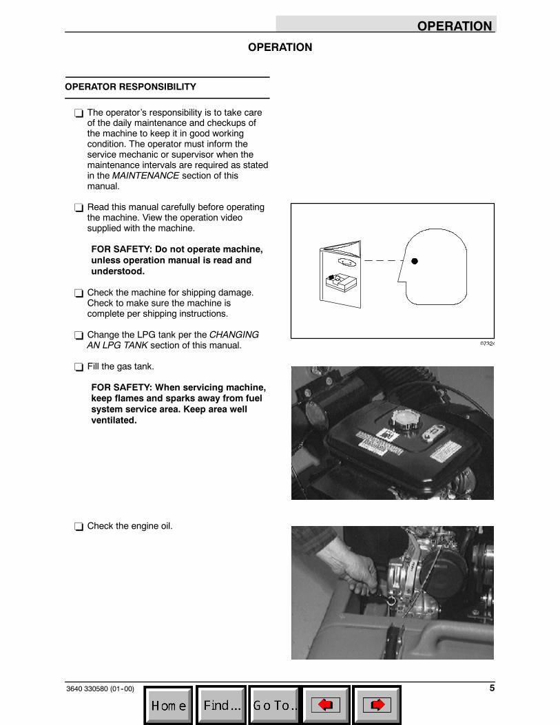
- Read this manual carefully before operatingthe machine. View the operation videosupplied with the machine.
FOR SAFETY: Do not operate machine,unless operation manual is read andunderstood.
- Check the machine for shipping damage.Check to make sure the machine iscomplete per shipping instructions.
- Change the LPG tank per the CHANGINGAN LPG TANK section of this manual.
- Fill the gas tank.
FOR SAFETY: When servicing machine,keep flames and sparks away from fuelsystem service area. Keep area wellventilated.
- Check the engine oil.
07324

OPERATION
3640 330580 (01--00)6
- Keep your machine regularly maintained byfollowing the maintenance information in thismanual. We recommend taking advantageof a regularly scheduled service contractfrom your Tennant representative.
- Order parts and supplies directly from yourauthorized Tennant representative. Use theparts manual provided when ordering parts.
- After the first 50 hours of operation, followthe recommended procedures stated in theMAINTENANCE CHART.
OPERATION
73640 330580 (01--00)
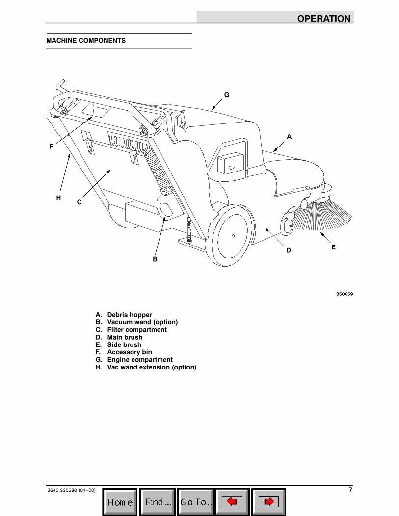
MACHINE COMPONENTS
A
B
C
D E
F
G
H
350659
A. Debris hopperB. Vacuum wand (option)C. Filter compartmentD. Main brushE. Side brushF. Accessory binG. Engine compartmentH. Vac wand extension (option)

OPERATION
3640 330580 (01--00)8
SYMBOL DEFINITIONS
These symbols identify controls, displays, andfeatures on the machine:
Start
Filter shaker switch
Side brush(es) down and on
Side brush(es) up and off
Main brush down pressure
Main brush down and on
Main brush up and off
Low engine oil indicator
Low battery / alternator indicator
Circuit breaker #1
OPERATION
93640 330580 (01--00)
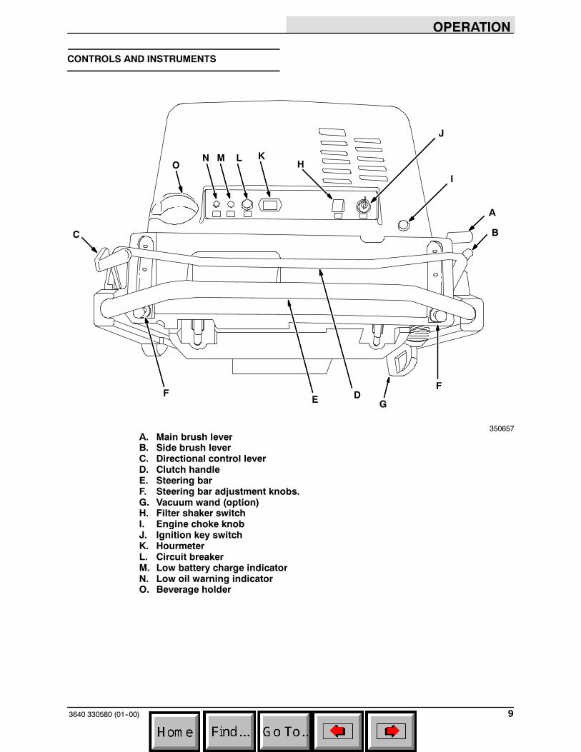
CONTROLS AND INSTRUMENTS
A
BC
DEF
F
G
H
I
J
KN M LO
350657A. Main brush leverB. Side brush leverC. Directional control leverD. Clutch handleE. Steering barF. Steering bar adjustment knobs.G. Vacuum wand (option)H. Filter shaker switchI. Engine choke knobJ. Ignition key switchK. HourmeterL. Circuit breakerM. Low battery charge indicatorN. Low oil warning indicatorO. Beverage holder

OPERATION
3640 330580 (01--00)10
OPERATION OF CONTROLS
DIRECTIONAL CONTROL LEVER
The directional control lever controls themachine’s speed and direction of travel. Themachine has three forward speeds: second, first,and third; one reverse speed; as well as neutraland park settings.
The speed selection pattern is designed to allowthe operator to move the control lever quicklybetween second speed and reverse. The neutralsetting is located midway between thesepositions. Since reverse and second speed will beused most often for routine sweeping, the areabetween these positions is called the workingrange. The directional control lever positions arelabeled near the base of the directional controllever in the following order:
PARK: Pull the directional control lever toward youas far as it will go. The directional control levershould always be in the PARK position whenstarting, stopping, or leaving the machineunattended while the machine is powered on.
REVERSE: Move the directional control lever tothe left, then one position forward from the PARKposition. The machine will move backward whenthe clutch handle is squeezed.
OPERATION
113640 330580 (01--00)
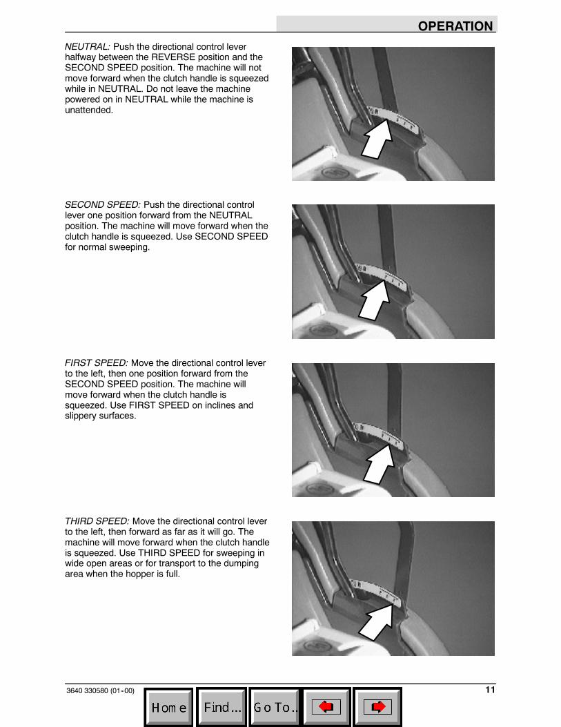
NEUTRAL: Push the directional control leverhalfway between the REVERSE position and theSECOND SPEED position. The machine will notmove forward when the clutch handle is squeezedwhile in NEUTRAL. Do not leave the machinepowered on in NEUTRAL while the machine isunattended.
SECOND SPEED: Push the directional controllever one position forward from the NEUTRALposition. The machine will move forward when theclutch handle is squeezed. Use SECOND SPEEDfor normal sweeping.
FIRST SPEED: Move the directional control leverto the left, then one position forward from theSECOND SPEED position. The machine willmove forward when the clutch handle issqueezed. Use FIRST SPEED on inclines andslippery surfaces.
THIRD SPEED: Move the directional control leverto the left, then forward as far as it will go. Themachine will move forward when the clutch handleis squeezed. Use THIRD SPEED for sweeping inwide open areas or for transport to the dumpingarea when the hopper is full.

OPERATION
3640 330580 (01--00)12
CLUTCH HANDLE
The clutch handle engages the machine’spropelling system when the direction control leveris positioned in a forward or reverse position. Thefarther the clutch handle is squeezed toward thesteering bar, the faster the machine will travel, upto its maximum in the selected position.
Braking: To stop the machine at any time,regardless of direction of travel, release the clutchhandle. The machine will immediately slow down,then stop completely.
MAIN BRUSH LEVER
The main brush lever raises and lowers the mainbrush. The main brush rotates automatically whenthe machine is powered on. The main brushrotates whether in the raised or lowered position.
Main brush down: Move the main brush lever tothe left, out of the raised position, then allow it tofall forward into the sweeping position.
Main brush up: Move the main brush leverbackward, then to the right to raise and set themain brush in the raised position.

OPERATION
133640 330580 (01--00)
SIDE BRUSH LEVER
The side brush lever raises and lowers the sidebrush. The side brush will rotate automaticallywhen lowered. The side brush does not rotatewhen raised.
Side brush down and on: Move the side brushlever to the right, out the raised position, thenforward to the desired brush down pressuresetting.
Side brush up and off: Move the side brush leverbackward, then to the left to raise and set the sidebrush in the raised position.
ENGINE CHOKE KNOB
The engine choke knob controls the choke.
On: For cold starting, pull the engine choke knobout.
Off: Push the choke knob in.
LOW OIL WARNING INDICATOR
The low oil warning indicator will illuminate whenthe engine oil level drops below a certain level.When the engine oil level is too low, the enginewill automatically shut itself off.
The engine will not restart and the indicator willnot go out until the proper amount of engine oilhas been added.

OPERATION
3640 330580 (01--00)14
LOW BATTERY CHARGE INDICATOR
The low battery charge indicator will illuminatewhen the battery charging system is notfunctioning properly. If the light remains on afterthe engine starts, contact TENNANT servicepersonnel.
STEERING BAR
Use the steering bar to steer the machine.
STEERING BAR ADJUSTMENT KNOBS
The steering bar adjustment knobs allow you tomove and lock the steering bar into a position thatis most comfortable for you. Pull both adjustmentknobs out at once to raise or lower the steeringbar.
OPERATION
153640 330580 (01--00)
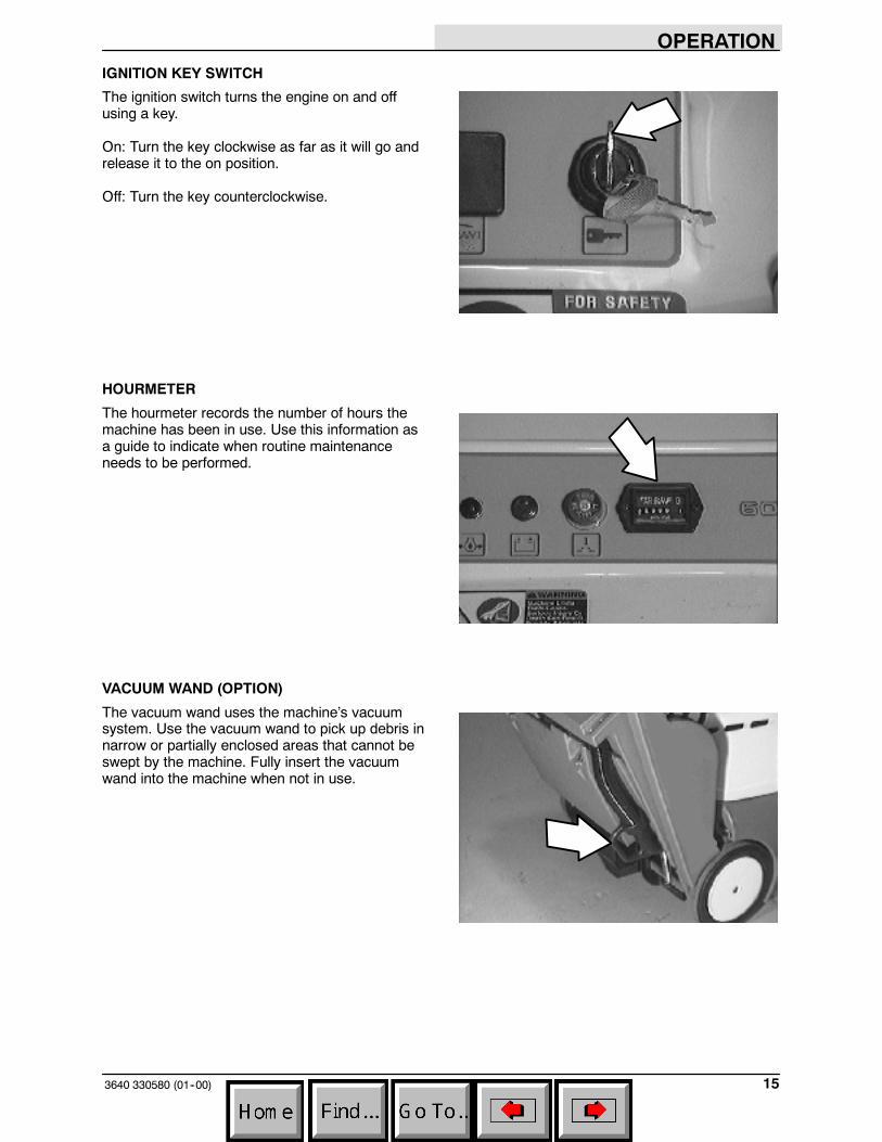
IGNITION KEY SWITCH
The ignition switch turns the engine on and offusing a key.
On: Turn the key clockwise as far as it will go andrelease it to the on position.
Off: Turn the key counterclockwise.
HOURMETER
The hourmeter records the number of hours themachine has been in use. Use this information asa guide to indicate when routine maintenanceneeds to be performed.
VACUUM WAND (OPTION)
The vacuum wand uses the machine’s vacuumsystem. Use the vacuum wand to pick up debris innarrow or partially enclosed areas that cannot beswept by the machine. Fully insert the vacuumwand into the machine when not in use.
OPERATION
3640 330580 (2--06)16
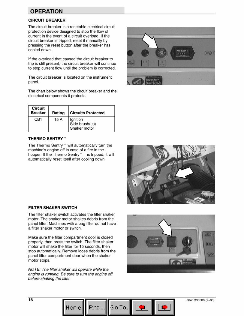
CIRCUIT BREAKER
The circuit breaker is a resetable electrical circuitprotection device designed to stop the flow ofcurrent in the event of a circuit overload. If thecircuit breaker is tripped, reset it manually bypressing the reset button after the breaker hascooled down.
If the overload that caused the circuit breaker totrip is still present, the circuit breaker will continueto stop current flow until the problem is corrected.
The circuit breaker Is located on the instrumentpanel.
The chart below shows the circuit breaker and theelectrical components it protects.
CircuitBreaker Rating Circuits Protected
CB1 15 A IgnitionSide brush(es)Shaker motor
THERMO SENTRYt
The Thermo Sentryt will automatically turn themachine’s engine off in case of a fire in thehopper. If the Thermo Sentryt is tripped, it willautomatically reset itself after cooling down.
FILTER SHAKER SWITCH
The filter shaker switch activates the filter shakermotor. The shaker motor shakes debris from thepanel filter. Machines with a bag filter do not havea filter shaker motor or switch.
Make sure the filter compartment door is closedproperly, then press the switch. The filter shakermotor will shake the filter for 15 seconds, thenstop automatically. Remove loose debris from thepanel filter compartment door when the shakermotor stops.
NOTE: The filter shaker will operate while theengine is running. Be sure to turn the engine offbefore shaking the filter.
OPERATION
173640 330580 (01--00)
HOW THE MACHINE WORKS
The operator steers the machine by using thesteering bar. The directional control lever controlsthe forward or reverse direction of the machine.The clutch handle engages the propelling systemwhen it is squeezed toward the steering bar. Theclutch handle will also stop the machine when it isreleased.
The side brush sweeps debris into the path of themain brush. The main brush sweeps debris fromthe floor into the hopper. The vacuum systempulls dust and air through the main brushcompartment and the dust filter.
When sweeping is finished, press the filter shakerswitch (option) to clean the panel filter (option) ifthe machine has these options. Clean the panelfilter compartment. Empty the hopper.
If the machine has a bag filter, check the filter bagand replace if full. Empty the hopper.
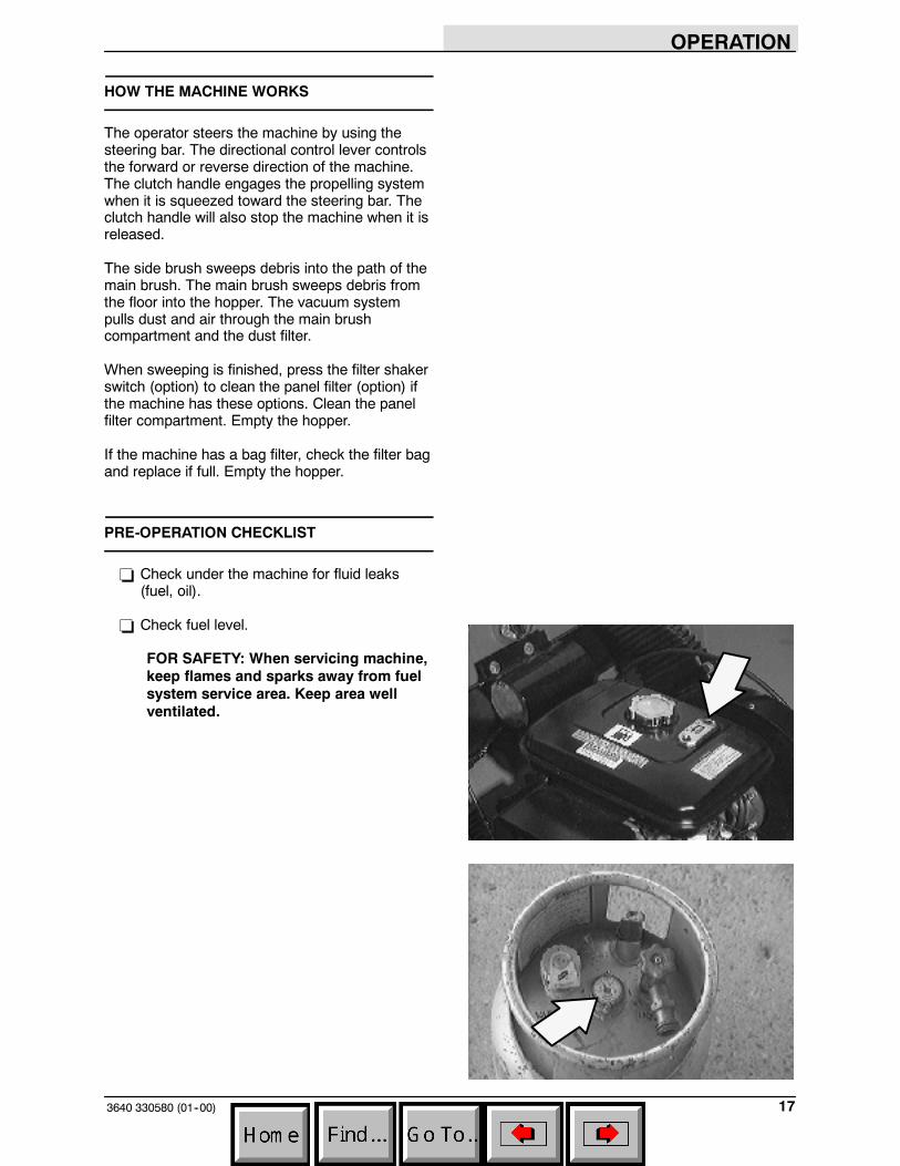
PRE-OPERATION CHECKLIST
- Check under the machine for fluid leaks(fuel, oil).
- Check fuel level.
FOR SAFETY: When servicing machine,keep flames and sparks away from fuelsystem service area. Keep area wellventilated.

OPERATION
3640 330580 (01--00)18
- Check the engine oil level.
- LPG powered machines: Check for LPGodor or frosting on hoses or componentsindicating an LPG leak.
- Check controls for proper operation.
- Check maintenance records to determineservice requirements.
OPERATION
193640 330580 (01--00)
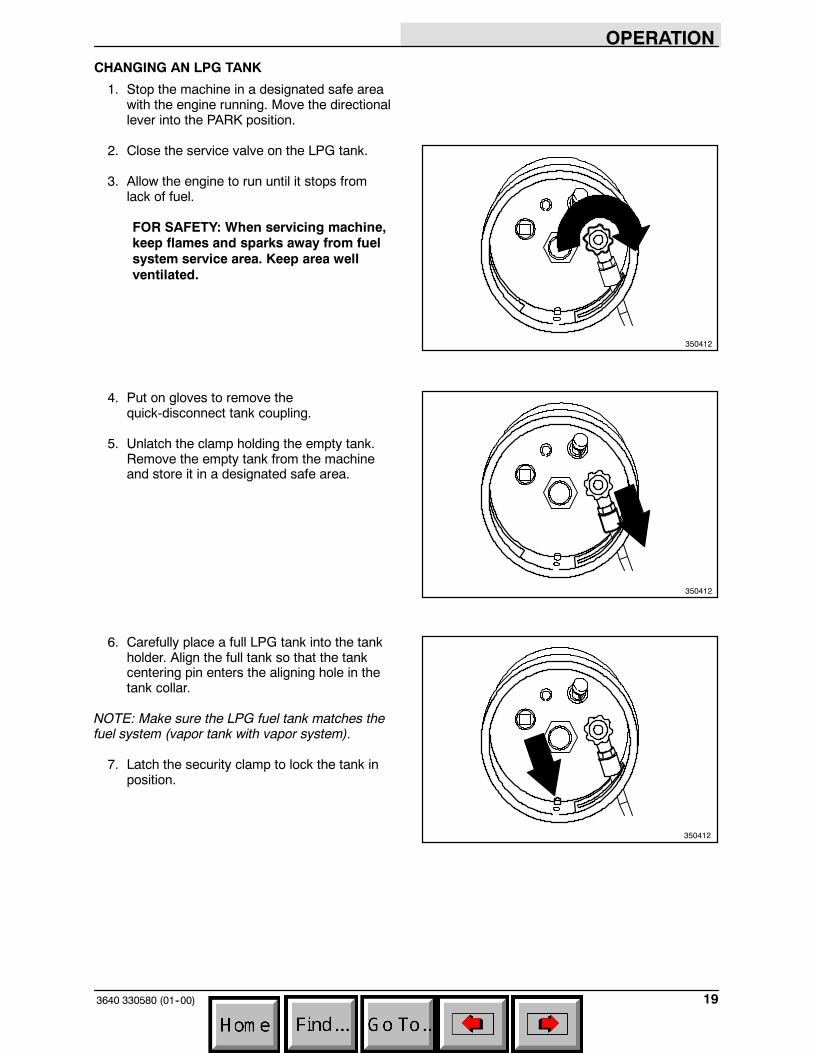
CHANGING AN LPG TANK
1. Stop the machine in a designated safe areawith the engine running. Move the directionallever into the PARK position.
2. Close the service valve on the LPG tank.
3. Allow the engine to run until it stops fromlack of fuel.
FOR SAFETY: When servicing machine,keep flames and sparks away from fuelsystem service area. Keep area wellventilated.
4. Put on gloves to remove thequick-disconnect tank coupling.
5. Unlatch the clamp holding the empty tank.Remove the empty tank from the machineand store it in a designated safe area.
6. Carefully place a full LPG tank into the tankholder. Align the full tank so that the tankcentering pin enters the aligning hole in thetank collar.
NOTE: Make sure the LPG fuel tank matches thefuel system (vapor tank with vapor system).
7. Latch the security clamp to lock the tank inposition.
350412
350412
350412
OPERATION
3640 330580 (01--00)20
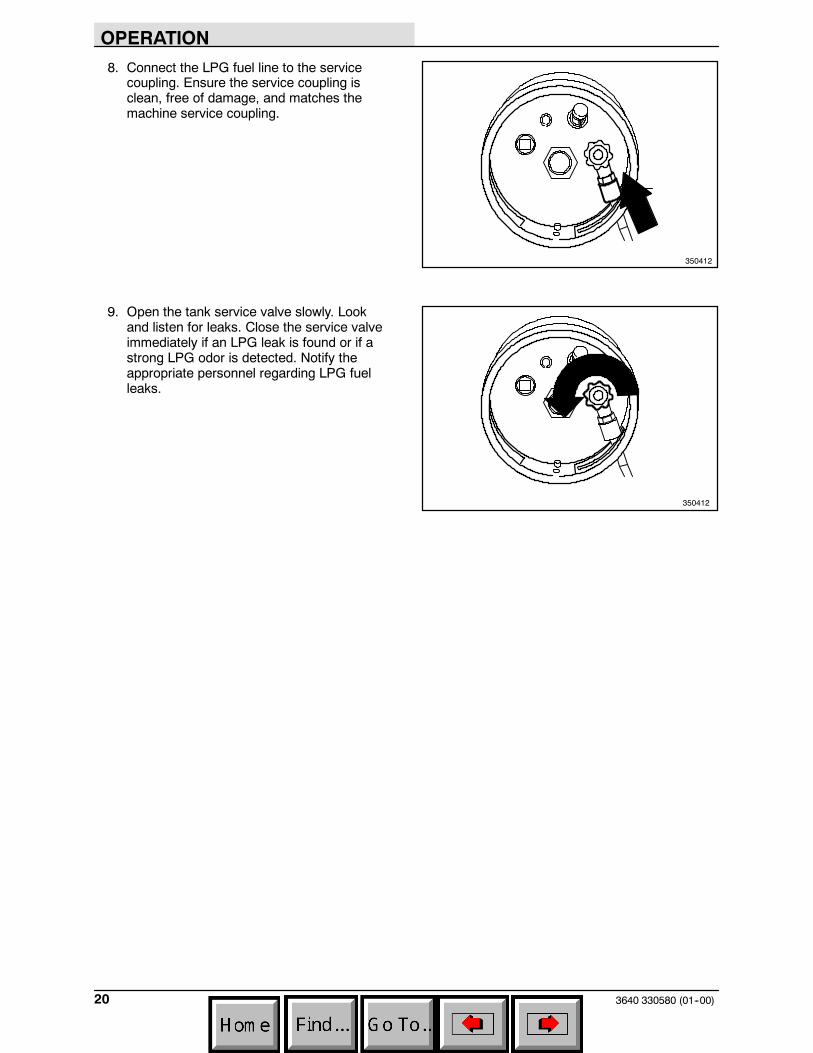
8. Connect the LPG fuel line to the servicecoupling. Ensure the service coupling isclean, free of damage, and matches themachine service coupling.
9. Open the tank service valve slowly. Lookand listen for leaks. Close the service valveimmediately if an LPG leak is found or if astrong LPG odor is detected. Notify theappropriate personnel regarding LPG fuelleaks.
350412
350412

OPERATION
213640 330580 (01--00)
STARTING THE MACHINE
1. LPG powered machines: Open the tankservice valve slowly.
NOTE: Opening the service valve too quickly maycause the check valve to stop the flow of LPGfuel. If the check valve stops the fuel flow, closethe service valve, wait a few seconds and openthe valve again more slowly.
2. If equipped with the vacuum lockoff system;For cold and hot starting -- Pull out chokeand crank engine for 3 to 5 seconds.Whilecontinuing to crank engine, siowly push inchoke.If equipped with the solenoid lockoff system;For cold starting -- Pull out choke and crankengine, once engine fires push in choke.For hot starting -- No choking required,simply crank engine.
3. Move the directional control lever into thedesired forward speed (second, first, orthird).
4. Gently squeeze the clutch handle to movethe machine forward.
NOTE: The farther the clutch handle is squeezedtoward the steering bar, the faster the machinewill travel, up to its maximum in the selectedposition.
5. Drive the machine to the area to be swept.

OPERATION
3640 330580 (01--00)22
SWEEPING AND BRUSH INFORMATION
Pick up oversized debris before sweeping. Flattenor remove bulky cartons from aisles beforesweeping. Pick up pieces of wire, twine, string,etc., which could become entangled in thebrushes or brush hub.
Plan the sweeping in advance. Try to arrange longruns with minimum stopping and starting. Sweepdebris from very narrow aisles into the main aislesahead of time. Do an entire floor or section at onetime. Drive the straightest path possible. Avoidbumping into posts or scraping the sides of themachine. Overlap the sweeping paths.
Polypropylene 8-double row main brush --Superior pick-up of sand, gravel, and paper litter.Polypropylene retains its stiffness when wet andcan be used indoors or outdoors with equalperformance.
Polypropylene Side Brush -- A good generalpurpose brush for sweeping of light to mediumdebris in both indoor and outdoor applications.This brush is recommended when bristles mayget wet.

OPERATION
233640 330580 (01--00)
SWEEPING
1. Drive the machine to the area to be swept.
2. Release the clutch handle to stop themachine.
3. Move the main brush lever to the left, out ofthe raised position, then allow it to fallforward into the sweeping position.
4. Move the side brush lever to the right, out ofthe raised position, then forward to thedesired brush down pressure setting.
5. Squeeze the clutch handle to beginsweeping.
6. Sweep as needed.

OPERATION
3640 330580 (01--00)24
STOP SWEEPING
1. Release the clutch handle.
NOTE: The machine will immediately slow down,then stop completely.
2. Move the main brush lever backward, thento the right to raise and set the main brush inthe raised position.
3. Move the side brush lever backward, then tothe left to raise and set the side brush(es) inthe raised position.

OPERATION
253640 330580 (01--00)
4. Move the directional control lever into thePARK position.
5. Shake the panel filter by pressing the filtershaker switch. The shaker motor will operatefor 15 seconds before stopping.
NOTE: Make sure the filter compartment isclosed securely before activating filter shaker.
6. Turn the machine power off.
7. LPG powered machines: Ensure the LPGtank service valve is closed.
OPERATION
3640 330580 (01--00)26
EMPTYING THE DEBRIS HOPPER
STANDARD HOPPER
Drive the machine to the area where debris iscollected.
Turn the machine power off.
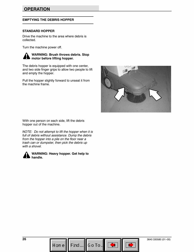
WARNING: Brush throws debris. Stopmotor before lifting hopper.
The debris hopper is equipped with one center,and two side finger grips to allow two people to liftand empty the hopper.
Pull the hopper slightly forward to unseat it fromthe machine frame.
With one person on each side, lift the debrishopper out of the machine.
NOTE: Do not attempt to lift the hopper when it isfull of debris without assistance. Dump the debrisfrom the hopper into a pile on the floor near atrash can or dumpster, then pick the debris upwith a shovel.
WARNING: Heavy hopper. Get help tohandle.

OPERATION
273640 330580 (01--00)
HOPPER DUMP ASSIST HANDLE (OPTION)
The dump assist handle allows easy removal andtransport of the debris hopper when it is full.
Turn the machine power off.
WARNING: Brush throws debris. Stopmotor before lifting hopper.
Raise the dump assist handle.
Place one foot on the hopper’s pivot point.
Lift the hopper out of the machine and onto thewheels. Transport the hopper to the locationwhere debris is collected.
WARNING: Heavy hopper. Get help tohandle.
NOTE: Do not attempt to lift the hopper when it isfull of debris without assistance. Dump the debrisfrom the hopper into a pile on the floor near atrash can or dumpster, then pick the debris upwith a shovel.

OPERATION
3640 330580 (01--00)28
REPLACING THE BAG FILTER (OPTION)
The bag filter (option) traps dust and smallparticles of debris. Check the bag filter daily andreplace it when it becomes full of debris.
To access the bag filter, remove the vacuum wandand unlatch the filter compartment hooks.
Install a new bag filter by placing the cardboardtab on the filter around the vacuum inlet tube.
The vacuum inlet tube is located at the top of filtercompartment, on the inside of the machine.
Latch the filter compartment door. Fully insert thevacuum wand into the machine.

OPERATION
293640 330580 (01--00)
CLEANING THE FILTER COMPARTMENT
The panel filter traps dust and small particles ofdebris. Press the filter shaker switch to shake thedebris from the panel filter each time the hopper isemptied. This debris collects in the filtercompartment. Clean the filter compartment daily.
Remove the vacuum wand and unlatch the filtercompartment hooks.
Lower and remove the filter compartment door bysliding it to the left off the pivot pins. Empty thedust and debris.
Replace and latch the filter compartment door.Fully insert the vacuum wand into the machine.

OPERATION
3640 330580 (01--00)30
POST-OPERATION CHECKLIST
Check this list of items after sweeping andemptying hopper:
- Check for wire or string tangled in thebristles of the main brush and sidebrush(es). Additional side brush optionshown.
FOR SAFETY: Before leaving orservicing machine, stop on levelsurface, turn off machine, and removekey.
- Check and, if necessary, wipe the vacuuminlet plate clean.
- LPG powered machines: Ensure the LPGtank service valve is closed.
- Check for fuel odor that indicates a fuel leak.
- Check under the machine for fluid leaks(fuel, oil).
- Check the skirts and seals for damage andwear.
- Check the bag filter (option) for fullness orshake the panel filter and clean the filtercompartment.
- Check the service records to determineroutine maintenance requirements.
OPERATION ON INCLINES
When operating the machine on an incline, usefirst speed for increased power and control. Themaximum rated climb and descent angle for themachine is 8_.
NOTE: To stop the machine at any time,regardless of direction of travel, release the clutchhandle. The machine will immediately slow down,then stop completely.
OPERATION
313640 330580 (01--00)
OPTIONS
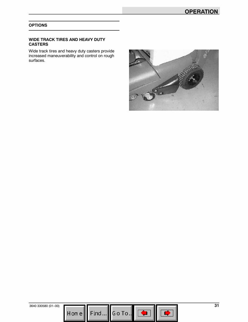
WIDE TRACK TIRES AND HEAVY DUTYCASTERS
Wide track tires and heavy duty casters provideincreased maneuverability and control on roughsurfaces.

OPERATION
3640 330580 (01--00)32
MACHINE TROUBLESHOOTING
Problem Cause Remedy
Excessive dusting Vacuum hose clogged Unscrew hose from vac wandhandle and clean
Brush skirts and dust seals wornor damaged
Replace brush skirts or dust seals
Filter bag full or panel filterclogged
Shake and / or clean or replacebag or panel filter
Vacuum wand hose damaged Replace vacuum wand hose
Vacuum wand not fully insertedinto machine
Insert fully
Vacuum inlet plate clogged Remove / clean plate. Cleanchamber if necessary
Vacuum fan failure Contact Tennant servicepersonnel
Poor sweeping performance Brush bristles worn Replace brushes
Main brush not touching floor Check brush linkage for binding orcontact Tennant service personnel
Debris caught in main brush drivemechanism
Remove debris from drivemechanism
Main brush drive failure Contact Tennant servicepersonnel
Side brush drive failure Contact Tennant servicepersonnel
Hopper full Empty hopper
Hopper / brush skirts worn ordamaged
Replace skirts
Machine will not propel or shift Transmission will not go into gear Contact Tennant servicepersonnel
Clutch arm not pulling belt tightenough
Adjust clutch cable length
Propel belt stop bar not adjustedproperly
Contact Tennant servicepersonnel
Machine will not start Thermo Sentryt tripped Reset Thermo Sentryt
Engine oil level low Check and fill
Fuel tank valve closed Open valve -- LPG tank valve orvalve below gasoline tank

MAINTENANCE
333640 330580 (01--00)
MAINTENANCE
1
2
3
4 5
6
7
8350841
MAINTENANCE CHART
Interval Key Description ProcedureLubricant/
Fluid
No. ofServicePoints
Daily 1 Engine oil Check with dipstick EO 14,5 Main brush and side
brush(es)Check for damage and wear -- 2 (3)
2 Skirts and seals Inspect -- 66 Bag filter (option) Check / replace if full -- 16 Panel filter Shake filter, clean compartment
door-- 1
2 Vacuum inlet plate Check / clean -- 150 Hours 1 Engine oil Change EO 1
1 Engine air filter Replace -- 11 Vacuum fan belt Check tension and wear -- 15 Main brush Rotate end for end and check
brush pattern-- 1
100 Hours 6 Panel filter Remove and clean -- 17 Wide track tires (option) Check for damage / pressure -- 28 Heavy duty casters
(option)Lubricate SPL 2
200 Hours 1 Sparkplug Check / replace -- 11 Gasoline fuel filter /
sediment bowlClean -- 1
500 Hours 3 Side brush motor(s) Check motor brushes -- 1 (2)
LUBRICANT/FLUIDEO Engine oil, 30 SAE -- CD/SF rated. . . .SPL Special lubricant, Lubriplate EMB grease (TENNANT part no. 01433--1). . .
MAINTENANCE
3640 330580 (01--00)34
LUBRICATION
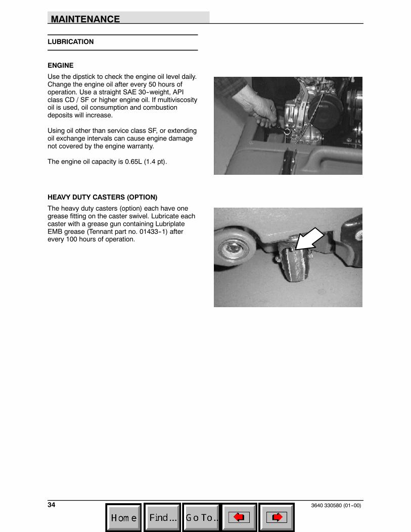
ENGINE
Use the dipstick to check the engine oil level daily.Change the engine oil after every 50 hours ofoperation. Use a straight SAE 30--weight, APIclass CD / SF or higher engine oil. If multiviscosityoil is used, oil consumption and combustiondeposits will increase.
Using oil other than service class SF, or extendingoil exchange intervals can cause engine damagenot covered by the engine warranty.
The engine oil capacity is 0.65L (1.4 pt).
HEAVY DUTY CASTERS (OPTION)
The heavy duty casters (option) each have onegrease fitting on the caster swivel. Lubricate eachcaster with a grease gun containing LubriplateEMB grease (Tennant part no. 01433--1) afterevery 100 hours of operation.

MAINTENANCE
353640 330580 (01--00)
FUEL SYSTEM
FUEL FILTER AND SEDIMENT BOWL
Gasoline powered machines are equipped with afuel filter and a sediment bowl to clean the fueland collect the debris.
The fuel filter and sediment bowl are locatedbelow the gasoline tank. Remove and clean thesecomponents every 200 hours of machine use.
FOR SAFETY: When servicing machine,keep flames and sparks away from fuelsystem service area. Keep area wellventilated.
GAS VALVE
The gas valve is located on the right--hand side ofthe fuel filter / sediment bowl assembly. The gasvalve shuts off the flow of gas to the engine.
When the valve is closed, the machine will run fora short time, then stop from lack of fuel. Open thevalve to start the machine.
MAINTENANCE
3640 330580 (01--00)36
ENGINE
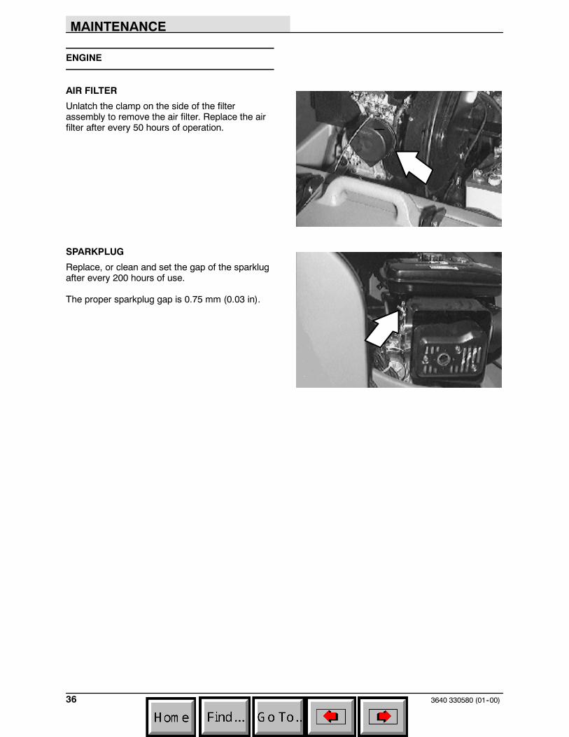
AIR FILTER
Unlatch the clamp on the side of the filterassembly to remove the air filter. Replace the airfilter after every 50 hours of operation.
SPARKPLUG
Replace, or clean and set the gap of the sparklugafter every 200 hours of use.
The proper sparkplug gap is 0.75 mm (0.03 in).
MAINTENANCE
373640 330580 (01--00)
SKIRTS AND SEALS
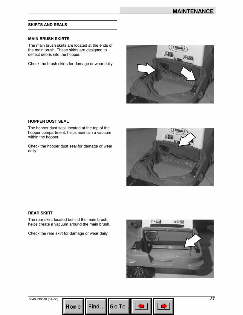
MAIN BRUSH SKIRTS
The main brush skirts are located at the ends ofthe main brush. These skirts are designed todeflect debris into the hopper.
Check the brush skirts for damage or wear daily.
HOPPER DUST SEAL
The hopper dust seal, located at the top of thehopper compartment, helps maintain a vacuumwithin the hopper.
Check the hopper dust seal for damage or weardaily.
REAR SKIRT
The rear skirt, located behind the main brush,helps create a vacuum around the main brush.
Check the rear skirt for damage or wear daily.
MAINTENANCE
3640 330580 (01--00)38
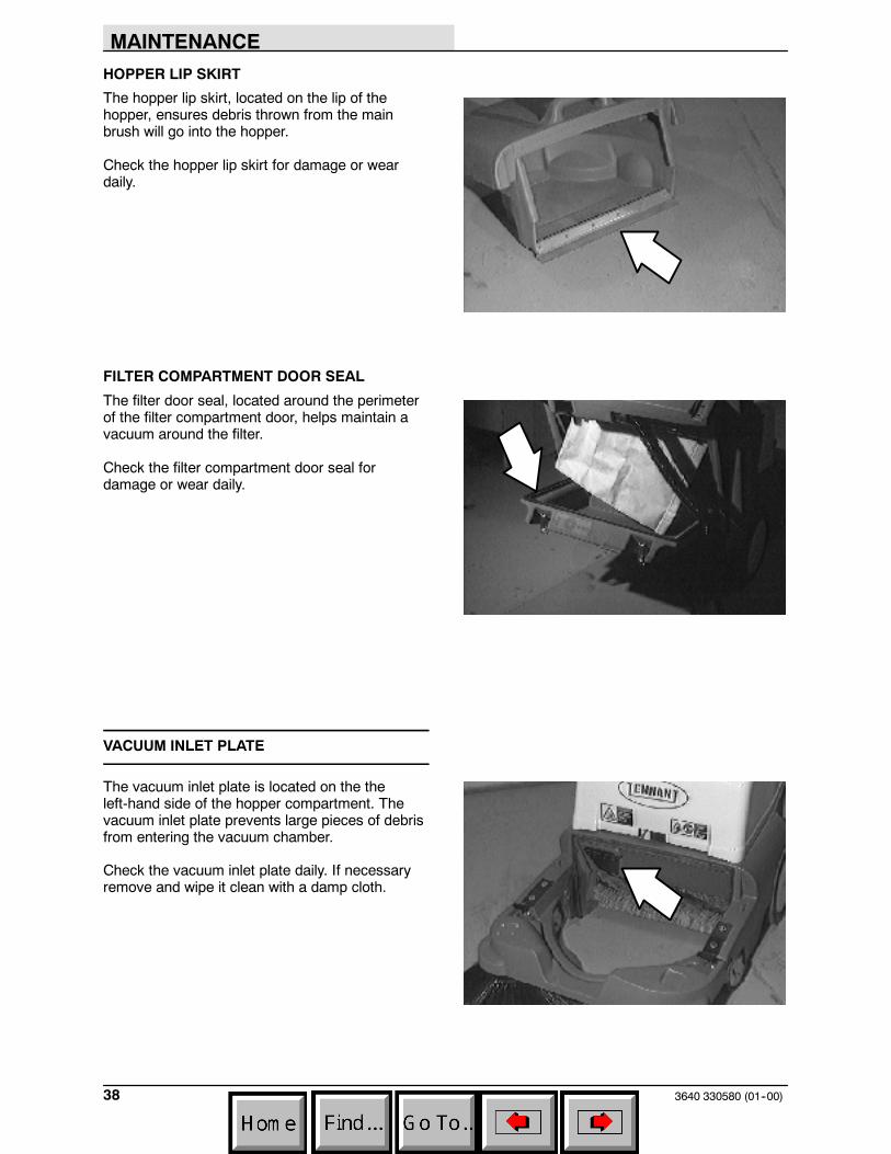
HOPPER LIP SKIRT
The hopper lip skirt, located on the lip of thehopper, ensures debris thrown from the mainbrush will go into the hopper.
Check the hopper lip skirt for damage or weardaily.
FILTER COMPARTMENT DOOR SEAL
The filter door seal, located around the perimeterof the filter compartment door, helps maintain avacuum around the filter.
Check the filter compartment door seal fordamage or wear daily.
VACUUM INLET PLATE
The vacuum inlet plate is located on the theleft-hand side of the hopper compartment. Thevacuum inlet plate prevents large pieces of debrisfrom entering the vacuum chamber.
Check the vacuum inlet plate daily. If necessaryremove and wipe it clean with a damp cloth.

MAINTENANCE
393640 330580 (2--08)
CLEANING THE PANEL FILTER
The panel filter filters the air pulled up from thehopper. The panel filter is equipped with a shakerto remove the accumulated dust particles.Remove and thoroughly clean the panel filter afterevery 100 hours of use.
To remove the panel filter, unlatch and lower thefilter compartment door.
Unlatch the panel filter retainer and remove thefilter.
To clean the panel filter, use one of the followingmethods:
D TAPPING -- Tap the filter gently on a flatsurface with the dirty side down. Do notdamage the edges of the filter element, orthe filter will not seat properly in the filtercompartment.
D AIR -- Blow air through the filter from theopposite the side of the fingertabs. Alwayswear eye protection when using compressedair.
FOR SAFETY: When servicing machine,wear eye and ear protection if usingpressurized air or water.

MAINTENANCE
3640 330580 (01--00)40
BRUSHES
MAIN BRUSH
The main brush spans the width of the machineand throws debris into the hopper.
Check the brush for damage and wear daily.Remove string or wire tangled in the main brushor the main brush hub.
Check the main brush pattern after every 50hours of use. Adjust the main brush pattern byloosening the nut at the left end of the brush armcrossbar.
Rotate the main brush after every 50 hours of usefor maximum brush life and sweepingperformance.
Replace main brush when bristle length is 9 to 12mm (.375 to .5 in).
REPLACING THE MAIN BRUSH
1. Turn the machine power off and move thedirectional lever into the PARK position.
FOR SAFETY: Before leaving orservicing machine, stop on levelsurface, turn off machine, and removekey.
2. The main brush pin, located on the left--handside of the machine, holds the main brush inplace. Turn the main brush pin 1/4 turncounter--clockwise and remove.If themachine has the (option) wide track wheelkit, lower the main brush to remove.

MAINTENANCE
413640 330580 (01--00)
3. Remove the debris hopper.
4. Pull the string guard and skirt back to avoiddamaging.
5. Pull the main brush out of the machinethrough the hopper opening.
6. Remove the brush hub from the worn brushand install it into the new brush.
7. Install the new main brush into the machine.
8. Insert the main brush pin through the hole inthe frame and into the main brush hub. Turnthe main brush pin 1/4 turn clockwise.
9. Replace the hopper.

MAINTENANCE
3640 330580 (01--00)42
CHECKING AND ADJUSTING MAIN BRUSHPATTERN
1. Apply chalk (or another material that will noteasily blow away), to a smooth, level sectionof the floor.
2. Lower the main brush in the chalked area.Allow the machine to sweep in the sameplace for 15 to 20 seconds.
NOTE: If chalk or other material is not available,allow the brush to spin on the floor for twominutes. A polish mark will remain on the floor.
3. Raise the main brush and move the machineaway from the chalked area. Turn themachine power off.
4. Observe the shape of the brush pattern. Ifthe brush pattern has parallel sides, thebrush does not need adjustment.
If the brush pattern is tapered, the mainbrush needs adjustment to straighten thebrush pattern.
A. To adjust brush taper, loosen the nut atthe left end of the brush arm crossbar.Move the crossbar up or down in theslide relative to the adjustment on theother side. Tighten the nut.
B. Check the brush again pattern andreadjust if necessary.
00601

MAINTENANCE
433640 330580 (01--00)
ROTATING THE MAIN BRUSH
1. Turn the machine power off and move thedirectional lever into the PARK position.
FOR SAFETY: Before leaving orservicing machine, stop on levelsurface, turn off machine, and removekey.
2. Turn the main brush pin 1/4 turncounter--clockwise and remove.
3. Remove the debris hopper.
4. Pull the main brush out of the machinethrough the hopper opening.
5. Remove the brush hub from the main brushand install it into the other end.
6. Install the main brush into the machine.
7. Insert the main brush pin through the hole inthe frame and into the main brush hub. Turnthe main brush pin 1/4 turn clockwise.
8. Replace the hopper.

MAINTENANCE
3640 330580 (01--00)44
SIDE BRUSH(ES)
The side brush(es) sweep debris along walls andedges into the path of the main brush.
Check the side brush(es) for damage and weardaily. Remove string or wire tangled in the sidebrush(es).
A side brush should be replaced when it no longereffectively sweeps for your application.
REPLACING THE SIDE BRUSH(ES)
1. Turn the machine power off and move thedirectional lever into the PARK position.
FOR SAFETY: Before leaving orservicing machine, stop on levelsurface, turn off machine, and removekey.
2. Reach underneath the side brush andremove the cotter pin that holds it on thedrive shaft.
3. Remove the worn brush.
4. Place a new side brush onto the drive shaftand secure with the cotter pin.
ELECTRIC MOTORS
Check the side brush motor(s) brushes every 500hours of operation. Replace the motor brusheswhen they are worn 9 mm (.375 in).

MAINTENANCE
453640 330580 (01--00)
BELTS AND CHAINS
VACUUM FAN BELT
The vacuum fan belt drives the vacuum system.Check the belt for wear and tension after every 50hours of operation.
Check belt tension by applying a force 1 kg (2 lb)at belt midpoint. The proper deflection should be5 mm (0.09 in).
WARNING: Moving belt and fan. Keepaway.
MAIN BRUSH BELT
The main brush drive belt is located behind theright rear tire. The belt drives the main brush. Theproper belt tension is automatically set by aspring--loaded idler.
STATIC DRAG CHAIN
The static drag chain prevents the buildup ofstatic electricity in the machine. The chain isattached to the backstop bracket.
Make sure the chain is always touching the floor.
CLUTCH CABLE
The clutch handle engages the machine’spropelling system. The clutch handle is connectedto the clutch cable. The clutch cable may stretchover time and require adjustment.
Adjust cable length by turning the nut at the baseof the clutch cable.

MAINTENANCE
3640 330580 (12--00)46
TIRES (OPTION)
The optional heavy duty rear tires are pneumatic.
Check the rear tires after every 100 hours ofoperation for damage. Check the rear tirepressure after every 100 hours of operation. Theproper tire pressure is 345 kPa (50 psi).

MAINTENANCE
473640 330580 (12--00)
PUSHING AND TRANSPORTING THEMACHINE
PUSHING THE MACHINE
If the machine becomes disabled, it can be easilypushed in neutral if necessary.
TRANSPORTING THE MACHINE
1. Position the front of the machine at theloading edge of the truck or trailer.
FOR SAFETY: Use truck or trailer thatwill support the weight of the machine.
NOTE: Empty the hopper before transporting themachine.
2. If the loading surface is not horizontal or ishigher than 380 mm (15 in) from the ground,use a winch to load machine.
If the loading surface is horizontal AND is380 mm (15 in) or less from the ground, themachine may be pushed onto the truck ortrailer.
3. To winch the machine onto the truck ortrailer, remove the hopper and place a strapthrough the front frame of the machine.Make sure the machine is in neutral and iscentered.
FOR SAFETY: When loading machineonto truck or trailer, use winch. Do notpush the machine onto the truck ortrailer unless the loading surface ishorizontal AND is 380 mm (15 in) or lessfrom the ground.
4. Position the machine onto the truck or traileras far as possible. If the machine starts toveer off the centerline of the truck or trailer,stop and center the machine.
MAINTENANCE
3640 330580 (12--00)48
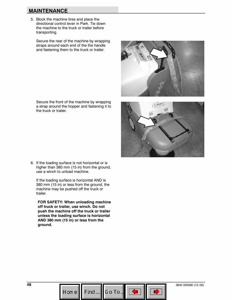
5. Block the machine tires and place thedirectional control lever in Park. Tie downthe machine to the truck or trailer beforetransporting.
Secure the rear of the machine by wrappingstraps around each end of the the handleand fastening them to the truck or trailer.
Secure the front of the machine by wrappinga strap around the hopper and fastening it tothe truck or trailer.
6. If the loading surface is not horizontal or ishigher than 380 mm (15 in) from the ground,use a winch to unload machine.
If the loading surface is horizontal AND is380 mm (15 in) or less from the ground, themachine may be pushed off the truck ortrailer.
FOR SAFETY: When unloading machineoff truck or trailer, use winch. Do notpush the machine off the truck or trailerunless the loading surface is horizontalAND 380 mm (15 in) or less from theground.

MAINTENANCE
493640 330580 (12--00)
STORING MACHINE
When storing the machine for extended periods oftime, the following procedures must be followed:
1. Raise the main and side brush(es).
2. Empty and clean the debris hopper.
3. Drain or disconnect and remove (LPG tank)fuel system.
4. Close the gasoline valve.
5. Change the engine oil.
6. Remove the spark plug, pour 30 cc (1 oz) ofengine oil into the cylinder. Slowly rotate thecrankshaft to distribute the oil. Replace thespark plug.
7. Clean the engine cooling fins.
8. Store the machine in a clean dry area.

SPECIFICATIONS
3640 330580 (6--02)50
SPECIFICATIONS
GENERAL MACHINE DIMENSIONS/CAPACITIES
Item Dimension/capacity
Length (Low / High steering bar position) 1428 / 1475 mm (56.25 / 58 in)
Width 820 mm (32.25 in)
Width (Wide track wheel kit option) 933 mm (36.75 in)
Height (Low / High steering bar position) 880 / 960 mm (34.7 / 37.7 in)
GVWR -- Gasoline engine 206 kg (455 lb)
GVWR -- LPG engine 220 kg (485 lb)
Track 775 mm (30.50 in)
Wheelbase 490 mm (19.36 in)
Main brush diameter 205 mm (8 in)
Main brush length 610 mm (24 in)
Side brush diameter 420 mm (16.5 in)
Sweeping path width, main brush only 610 mm (24 in)
Sweeping path width, main brush and one sidebrush
815 mm (32 in)
Sweeping path width, main brush and two sidebrushes
1015 mm (40 in)
Hopper capacity -- Maximum 85 L (3.0 cu ft)
Hopper capacity -- Usable 42.5 L (1.5 cu ft )
Panel filter area 3.62 sq m (39 sq ft)
Bag filter volume 17 L (0.6 cu ft)
GENERAL MACHINE PERFORMANCE
Item Measure
Maximum forward speed -- first speed 1.5 kmh (0.9 mph)
Maximum forward speed -- second speed 2.7 kmh (1.7 mph)
Maximum forward speed -- third speed 5.0 kmh (3.1 mph)
Maximum reverse speed 2.2 kmh (1.4 mph)
Minimum steering diameter 1588 mm (62.5 in)
Minimum turning radius 794 mm (31.25 in)
Maximum rated climb and descent angle 8_
Fuel consumption -- Gasoline engine 0.75 L/hr (0.2 gal/hr)
Fuel consumption -- LPG engine 0.4 kg/hr (0.9 lb/hr)

SPECIFICATIONS
513640 330580 (12--00)
POWER TYPE
Engine Type Ignition Cycle Aspiration Cylinders Bore Stroke
OHV Gas --magneto
4 Natural 1 67 mm(2.14 in)
49 mm(1.93 in)
LPG -- SolidState
Displacement Net power, governed Net power, maximum
172 cc (10.5 cu in) 3.6 hp @ 2400 rpm 6 hp @ 4000 rpm
Fuel Cooling system Electrical system
Automotive regulargasoline, 87 octaneminimum, unleaded. Fueltank: 3.6L (0.95 gal)
Air Alternator output13.5 V / 9.6A @ 2400rpm
LPG, (vapor)Fuel tank: 9 kg (20 lb)
12 V Battery--260 cca
Governed speed, under load
2400 rpm maximum
Engine lubricating oil with filter
0.65L (1.4 pt) 30 SAE--CD/SF rated engine oil
ELECTRIC MOTORS
Type Use VDC / Amp Kw (hp)
Electric Motors Side brush(es) (disk) 13 V / 4.25 A 0.075 (.1)
TIRES
Location Type Size
Front (2) Casters 35 mm wide x 127 mm OD (1.375 in wide x 5 in OD)
Rear (2) Solid 45 mm wide x 305 mm OD (1.75 in wide x 12 in OD)

SPECIFICATIONS
3640 330580 (12--00)52
960 mm(37.7 in)
820 mm(32.25 in)
815 mm(32 in)
1475 mm(58 in)
610 mm(24 in)
350910MACHINE DIMENSIONS

INDEX
533640 330580 (12--00)
INDEX
B
Bag filter replacement, 28
Battery, low charge indicator, 14
BeltsMain brush, 45Vacuum fan, 45
Braking, stopping machine, 12
Brush information, 22
BrushesMain brush, 40Main brush pattern, checking, adjusting, 42Main brush, rotation, 43Replacing main brush, 40Replacing side brush(es), 44Side brush(es), 44
C
Cable, clutch, 45
Chain, static drag, 45
Choke, engine, 13
Circuit breaker, 16
Clutch cable, 45
Clutch handle, 12
ControlsClutch handle, 12Directional control lever, 10Engine choke knob, 13Ignition key switch, 15Main brush lever, 12Side brush lever, 13Steering bar, 14Steering bar adjustment knobs, 14
Controls and Instruments, 9
D
Directional control lever, 10
E
Electric motors, 44
Electrical system, Circuit breaker, 16
EngineAir filter, 36Sparkplug, 36
Specifications, 51
F
Filter compartment, Cleaning panel filtercompartment, 29
Filter shaker switch (option), 16
FiltersAir filter (engine), 36Bag filter replacement, 28Panel filter cleaning, 39
Fuel systemFuel filter, 35Gas valve, 35Sediment bowl, 35
Fuel tank -- LPG, Changing LPG fuel tank, 19
H
HopperDump assist handle emptying (option), 27Standard hopper emptying, 26
Hourmeter, 15
I
IndicatorsLow battery charge indicator, 14Low oil warning indicator, 13
InstrumentsHourmeter, 15Low battery charge indicator, 14Low oil warning indicator, 13
K
Key, ignition switch, 15
L
LeversDirectional control lever, 10Main brush lever, 12Side brush lever, 13
LPG fuel tank, changing, 19
Lubricationengine, 34heavy duty casters (option), 34

INDEX
3640 330580 (12--00)54
M
Machine, Storage, 49
Machine components, 7
Machine dimensions, 52
Machine troubleshooting, 32
Main brush, 40Checking and adjusting brush pattern, 42Replacement, 40Rotation, 43
Main brush lever, 12
Maintenance, Recommended, 6
Maintenance chart, 33
Motors, electric, 44
O
Oil, low warning indicator, 13
OperationChanging an LPG fuel tank, 19How the machine works, 17Post--operation checklist, 30Pre--operation checklist, 17Starting the machine, 21Stop sweeping, 24Stopping the machine, 12Sweeping, 23Sweeping and brush information, 22Sweeping on inclines, 30
Operation of controls, 10
Operator responsibility, 5
OptionsFilter shaker switch, 16Hopper dump assist handle, 27Panel filter, 39Wide track tires and casters, 31
P
Panel filter, Cleaning, 39
Panel filter compartment, Cleaning, 29
Plate, vacuum inlet, 38
Pushing and transporting machine, 47
Pushing machine, 47
Pushing the machine, 47
S
SafetyLabels, 4Precautions, 3
Side brush lever, 13
Side brush(es) replacement, 44
Skirts and sealsFilter compartment door seal, 38Hopper dust seal, 37Hopper lip skirt, 38Main brush skirts, 37Rear skirt, 37
Sparkplug, 36
SpecificationsClimb and descent angles, maximum, 50Electric motors, 51Engine, 51Fuel consumption, 50Machine capacities, 50Machine dimensions, 50Machine performance, 50Tires, 51Traveling speeds, 50Turning radius, 50
Steering bar, 14
Steering bar adjustment knobs, 14
Storing machine, 49
Sweeping, 23
Sweeping and brush information, 22
SwitchesFilter shaker switch (option), 16Ignition key switch, 15
Symbols, definitions, 8
T
Thermo Sentry, 16
Tires, 46Specifications, 51
Transporting machine, 47
Transporting the machine, 47
Troubleshooting chart, 32
V
Vacuum inlet plate, 38
Vacuum wand, 15