Gasket standards
40
Product Range Manual Issue 3
-
Upload
siva-raman -
Category
Documents
-
view
379 -
download
9
description
gzsket
Transcript of Gasket standards

Product Range ManualIssue 3

James Walker Moorflex was created by
merging Moorside and James Walker
Metaflex – two James Walker Group
companies which bring together over 100
years of experience at the forefront of sealing
technology.
Their mutual commitment to manufacturing
excellence, service, research and
development, together with their international
reputation, ensure that Moorflex is uniquely
placed to deliver the best products, backed
by the finest service, world-wide.
This commitment is borne out through the
most comprehensive stock availability in the
gasket industry, a 24 hour emergency
breakdown service, plus the strategic
location of manufacturing and service
facilities throughout the world.
All James Walker Group companies and
distributors offer full technical support to
their customers.
2
At your service...
The Company
…over 100 years ofsealing technology experience
In the world of sealing technology,
James Walker®, Moorside® and
Metaflex® are three of the most
widely known and respected brand
names, with an enviable reputation
for quality and reliability. For many
users they are the first choice for
trouble-free operations.
…brand namesyou can trust
IndexPage
2 The Company4 The Product Profile6 Non-Metallic Gaskets
11 Flange Insulation Sets14 Semi-Metallic Gaskets29 Metallic Gaskets

Throughout the world the oil, gas, petroleum
and chemical processing industries operate
in environments where only the strongest
survive.
The precision engineering of materials and
their supply, wherever and whenever they
are required, is fundamental in order to gain
the trust of operators in these most
demanding technologies.
Our aim is to supply quality products and
services and to fulfil our customers’
expectations. This is underpinned by our
Quality System approvals to ISO 9001:2008,
API Spec Q1-Standard 6A and 17D, which
are supplemented by many company and
independent authority approvals.
Moorflex takes great pride in having achieved
universal acceptance for providing gaskets
used in sealing applications where extreme
mechanical and thermal performance
demands are considered routine.
There are many companies in the sealing
industry. Very few can boast the quality of
products, quality of service and quality of
people found at Moorflex.
3
A world-wide reputation for quality...
LICENSED UNDERAPI Spec. 6A-0038
API 17D-0085
Certificate No. Q05429BS EN ISO 9001:2008

IntroductionJames Walker Moorflex gaskets set the
standards for sealing technology excellence
world-wide. Metal, graphite, PTFE, non-
metallic and semi-metallic; the range of
gasket materials available is as diverse as
the operating environments to which they
are subjected. Wherever a pipe or valve is
connected there’s a Moorflex gasket to
ensure the join is safe, strong and totally
reliable – from reactors to heat exchangers,
pipelines to pressure vessels.
4
SupportservicesIn order to provide the best in
service and reduce the costs of
downtime, Moorflex has
established a network of
manufacturing and service centres
world-wide. This network is
continually being reviewed and
expanded to meet the constantly
rising demands of the energy
industries.
Services offered in conjunction
with other James Walker Group
companies include:
Joint Integrity Programme.
Tension control fasteners.
The Product Profile

Ring Joint GasketsThe R, RX and BX series ofring joint gaskets are designedto meet API, ASME and BSstandards. Moorflex islicensed by the AmericanPetroleum Institute to applythe API monogram to gasketsin accordance with API 6APSL4.
Solid Metal GasketsFlat and profiled metallicgaskets are available to meetall international standards andspecifications. Special gasketscan also be developed tosatisfy individual requirements.
Flange Insulation Setsand PTFE Inner RIngsfor RIng Joint GasketsSuitable for the electricalisolation of pipelines and plantin cathodic protection systemsand/or hazardous areas.
Multiple PressureGasketsSemi-metallic gaskets capableof satisfying the completepressure range of a singlenominal bore pipeline – onegasket fits all class ratings.
Kammprofile GasketsMetakamm®; gaskets withgrooved faces and sealinglayers for heat exchangers,vessels, reactors and flangedconnections.
Metagraf GasketsMetal gaskets with groovedfaces and sealing layers forheat exchangers, vessels,reactors and flangedconnections.
Corrugated GasketsResilient, metal gasketssuitable for a wide range offlanged connections.
Metal Jacketed GasketsWidely used in heatexchangers, pressure vessels,valves and pumps, metaljacketed gaskets feature a soft,pliable filler core encased inmetal, to offer chemical andthermal resistance in diverseoperating conditions.
PTFE GasketsFlat gaskets with a highchemical resistance, suppliedeither as solid or envelopedesigns for pipe flanges andvessels.
Spiral Wound GasketsMetaflex® spiral woundgaskets are manufacturedfrom a v-shaped metal strip,spirally wound with an inlay offiller between each turn.Spiral wound gaskets areavailable in both standard andnon-standard designs.
Metal ReinforcedGraphiteThese resilient gaskets aremanufactured from high purityexpanded graphite, reinforcedwith metallic inserts to easeinstallation and enhanceperformance.
Soft Cut GasketsNon-metallic gaskets in a widerange of materials (includingmaterials to replace allasbestos products) forstandard and non-standardflanges.
Custom DesignedGasketsSpecial designs (andassociated components) tomeet the requirements ofOriginal EquipmentManufacturers.
Rubber Coated RingJoint GasketsReusable ring joint typegaskets used in the testing ofvalves and well headassemblies.Rubber coating preventsdamage to flanges and groovescuffing.
Machined GasketsWorking in conjunction withour customers, Moorflex hasconsiderable experience indesigning and manufacturinggaskets for all applications.
5
Flange ProtectorsHighly cost-effective andreusable flange protectorsto keep flanges safe fromhazardous corrosion that cancause joint leakage or failure.

6
IntroductionJames Walker produce cut gaskets andsheet jointings in a wide range of non-metallic materials. Gaskets are availableready-cut in most common flange sizes(ASME, DIN, etc) and customer parts canbe easily produced to your requirementsusing state-of-the-art CAD/CAM water-jetcutting equipment.
Non-Metallic gasket materialsElastomers
Nitrile, neoprene, ethylene-propylene,silicone and fluorocarbon, just to name afew, are among the many grades ofelastomer gasket material available fromJames Walker. There is a wide range ofspecification grades to internationallyrecognised industrial and militaryrequirements as well as “commercial”grades for general purpose applications.
Cork-Elastomer
The Nebar® range of cork-elastomers isspecified by customers world-wide. TheNebar® range is substantial, with gradescovering applications from high voltageswitchgear to aircraft fuelling equipment.
Calendered Fibre
A range of Compressed Non Asbestos Fibrecalendered jointing materials (Chieftain®,Centurian®, Sentinel®, and Inca), coversmost applications previously served byCompressed Asbestos jointings. The fibresused are typically carbon, glass and aramidor a mixture of these fibres.
The maximum temperature capabilities are,however, slightly reduced compared toasbestos, and the maximum temperaturelimits reduce with increasing thickness.Therefore care should always be taken touse the thinnest material wherever possible.
PTFE
Fluolion® Integra White, and Fluolion®
Integra Blue, are biaxially-orientated, filledPTFE materials. These are PTFE materialshaving improved creep resistance to ensuregreater reliability in service. They displayoutstanding chemical resistance, and theIntegra Blue grade has increased softnessand conformability for use on glass linedflanges or flanges having low bolt-loadcapacity.
Expanded Graphite
Supagraf® is available in a variety of grades,from plain un-reinforced sheet to nickel andstainless steel foil grades, as well as TangedT10, which has a tanged stainless steelreinforcing layer, giving superior physicalstrength and crush resistance.
Features
• Excellent chemical resistance.
• Exceptionally wide temperature range:from up to 400°C in oxidisingenvironments and under certaincircumstances, to 2500°C in inertconditions.
• Excellent resistance to stress relaxation,even at elevated temperatures.
• High levels of joint stability.
• Outstanding sealing integrity over extended periods.
• Accommodates flange distortions wheretraditional sheet jointings fail to seal.
• Fire safe.
• Exceptionally low leachable chloridecontent to resist corrosion.
• Totally compatible with steam, air andwater.
• Recommended for use with heat transferfluids and demineralised water.
Non-Metallic Gaskets
Cut gasketsand servicesThe Cut Gasket service isdedicated to meeting industry’simmediate needs for precisiongaskets produced from sheetjointing materials.
Moorflex holds stocks of gasketsto suit flange profiles found in allsectors of industry.
EmergencyManufacture
In the unlikely event of not havingparticular gaskets availableimmediately from stock, JamesWalker can readily manufacturethem, using highly accurateCAD/CAM controlled water-jetcutters. These machines are pre-programmed with every gasketdesign to national andinternational standards. Largestocks of non-asbestos sheetjointings, rubber and Supagraf®
products in all standardthicknesses are always available.
This same technology enablesany shape, size or quantity of non-standard cut gaskets to beproduced to the highest precisionstandards, working fromcustomers’ CAD/CAM files senton disk or via e-mail. Additionally,profiles can be digitised fromdrawings, samples or templates,with no need for tooling.
James Walker’s state-of-the-artwater-jet cutters operate with allmajor CAD languages. Nestingpattern software, combined withvideo acquisition equipment tocapture the shape of a sheet,ensures the maximum number ofgaskets is produced with theminimum material wastage.
These systems are proven to behighly economical for prototypecutting as well as for large batchruns. For metallic materials, suchas Supagraf® Tanged JointingT10, an abrasive water-jet cutteris utilised. This ensures a cleancut and eliminates the hazardoussharp edges which can occurwhen using conventional presscutting methods.

7
Chieftain®
DESCRIPTION Premium grade universal sheetjointing. Contains an advancedcarbon fibre material and a nitrilerubber (NRB) binder. Anti-stickfinish to both surfaces is suppliedas standard
PRIME FEATURES Carbon fibre for strength andstability450°C maximum temperatureOutstanding chemical and steamresistanceUser friendly – easy to cut, handleand remove from flanges
SPECIFICATIONS Easily meets the requirements ofBS7531 Grade XSuitable for ASME Class 300flange ratings to at least 260°C
Centurion®
DESCRIPTION A high performance sheet jointingbased on glass and aramid fibreswith a nitrile rubber (NBR) binder.An anti-stick finish to bothsurfaces is supplied as standard
PRIME FEATURES Well proven on industrial plantsworldwideRecommended for most fluidmediaChemically and thermally stablefor duties up to 440°CNon-pigmented
SPECIFICATIONS Meets the requirements ofBS7531 Grade X
BAM approved for use withgaseous oxygen at up to10MPa/100bar and 85°C
Sentinel®
DESCRIPTION General-purpose sheet jointing.Comprises compressed aramidfibres with nitrile rubber (NBR)binder. An anti-stick finish to bothsurfaces is supplied as standard
PRIME FEATURES Replaces CAF for most industrialdutiesOffers outstanding performancefor its classSuitable for a wide range ofmedia
SPECIFICATIONS Exceeds the propertyrequirements of BS7531Grade Y.WRAS approved for use withhot and cold potable water upto 85°C
IncaDESCRIPTION A high quality, reliable,
economically priced jointingbased on glass and aramid fibrescombined with a nitrile (NBR)binder. Anti-stick finish to bothsurfaces is supplied as standard
PRIME FEATURES A durable jointing for generalpurpose, medium performance,duties
Suitable for steam, condensate,water, oils, solvents and a widerange of other media
Value engineered to provideexcellent value for money
SPECIFICATIONS Readily meets the propertyrequirements of BS7531Grade Y.
WRAS approved for use with hotand cold potable water up to85° C
Fluolion® INTEGRA BLUE
DESCRIPTION General purpose PTFE-basedsheet jointing specially stabilisedand mechanically treated toimprove multi-directionalstrength, combat creep andimprove resilience for flangejointing duties.
TYPICALAPPLICATIONS
Flanged joints on plant thathandles aggressive fluid media,especially where hygiene is toppriority – such as in the food andelectronic industries. Especiallysuited to applications with weakor lightly loaded flanges, as wellas standard flange duties.
PRIME FEATURES Highly recommended for dutieswith caustic alkalis and strongacids, at elevated temperaturesand moderate concentrations
Can be used at cryogenictemperatures
High compressibility for effectivesealing on lightly loaded flanges
Inherently clean, non-toxic andnon-tainting
Outstanding resistance to a verywide range of chemical media
SPECIFICATIONS Complies with requirements ofFDA Regulations for food use

8
Fluolion® INTEGRA WHITE
DESCRIPTION Specially stabilised PTFE sheetmaterial, mechanically treated toimprove multi-directionalstrength, combat creep andimprove resilience for flangejointing duties.
TYPICALAPPLICATIONS
Flanged joints on plant thathandles extremely aggressivefluid media. Also where hygieneis top priority – such as in thepharmaceutical, food andelectronic industries
PRIME FEATURES Highly recommended for dutieswith strong acids and oxidisingagents at elevated temperaturesand all concentrations
Outstanding resistance to a verywide range of chemical media
Inherently clean, non-toxic andnon-tainting
Can be used at cryogenictemperatures
Displays compressibility andrecovery characteristics close tothose of many non-asbestos fibrejointings
SPECIFICATIONS Complies with requirements ofFDA Regulations for food use,and USP 25, Class V,classification of plastics forpharmaceutical service
Supagraf® PLAIN JOINTING
DESCRIPTION Sheet jointing of 98% pureexfoliated graphite. An Ultra HighPurity (99.8%) grade is availablefor nuclear industry applications
PRIME FEATURES Widest temperature range
Potable water duties andrepeated use with foodstuffs
Very easy to cut – but largegaskets may need support duringcarriage and fitting
SPECIFICATIONS WRAS approved for use withhot and cold potable water up to85°C
Supagraf®
TANGED JOINTING T10
DESCRIPTION Sheet jointing of 98% pureexfoliated graphite reinforced witha central layer of 0.1mm thicktanged stainless steel.
The graphite is compressed ontothe perforated metal sheet to givea secure mechanical lock withoutadhesive
PRIME FEATURES Exceptional resistance to blow-out and crushing
Anti-stick coating available
Extra strength for ease ofhandling and fitting
Supagraf® LAMINATED JOINTING S10
DESCRIPTION Sheet jointing of 98% pureexfoliated graphite with a bondedcentral layer of 50μm thickstainless steel foil. Sheets thickerthan 2mm have two layers ofmetal foil and three of graphiteof density 1Mg/m3
PRIME FEATURES Extra strength for ease ofhandling and fitting
Excellent sealing integrity
Can be cut with hand tools
Supagraf® LAMINATED JOINTING N7
DESCRIPTION This material has all the attributesof Supagraf® Laminated JointingS10, above, with the followingimportant exceptions:
Contains layer/s of 13μm thicknickel foil instead of stainlesssteel
Graphite density: 0.7Mg/m3
PRIME FEATURES Extra strength for ease ofhandling and fitting
Excellent sealing integrity
Can be cut with hand tools

9
Sheet jointingsChemical suitability guide
Due to the complexity of making a recommendation for any given duty, this section on chemical suitabilityis intended only as a guide. The possible effect of elevated temperatures should be considered whendetermining the compatibility of these products with a chemical. If necessary, please contact our technicalservices team for assistance.Dowtherm® is a registered trademark of Dow Chemical Company Limited. Freon® is a registered trademarkof EI DuPont de Nemours & Company or its affiliates. KLEA® is a registered trademark of ICI C & P Ltd.
Notation:� Suitable product
Where chemical compatibility is not indicated, or a chemical is notlisted, please consult our technical services team for arecommendation to be made.
SHEET JOINTINGSSTEAM � � � � � �
STEAM CONDENSATE � � � � � �
WATER � � � � � �
AIR � � � � � �
ACETIC ACID � � 50% 50% � �
ACETONE � � � � � �
ACETYLENE � � � � � �
ADIPIC ACID � � � � � �
ALUMINIUM CHLORIDE � � NO � � �
AMMONIA (Anhydrous, dry) � � � � � �
AMMONIA (wet) � � NO � � �
AMMONIUM CHLORIDE � � NO � � �
AMMONIUM HYDROXIDE � � 10% � � �
ANILINE � � � � � �
BENZENE � � � � � �
BITUMEN & HEAVY BOTTOMS � � � � � �
BLACK LIQUOR � � NO � 30°C NOBLEACH SOLUTIONS � � NO NO � �
BOILER FEED WATER � � � � � �
BRINE � � � � � �
BROMINE NO NO NO NO � �
BUNKER FUEL � � � � � �
BUTANE � � � � � �
CALCIUM CHLORIDE � � � � � �
CALCIUM HYDROXIDE � � � � � NOCALCIUM HYPOCHLORITE � � NO NO � �
CARBON DIOXIDE � � � � � �
CARBON DISULPHIDE NO NO NO NO � �
CARBON TETRACHLORIDE � � NO NO � �
CHLORINE (dry) � � � � � �
CHLORINE (wet) � NO NO NO � �
CHROMIC ACID NO NO NO NO NO �
CREOSOTE � � � � � �
DIESEL OIL � � � � � �
DIETHYL ETHER � � � � � �
DOWTHERM®� � NO NO � �
ETHANE � � � � � �
ETHANOLAMINES � � � � � �
ETHER � � � � � �
ETHYL ALCOHOL (Ethanol) � � � � � �
ETHYLAMINE � � � � � �
ETHYLENE � � � � � �
ETHYLENE GLYCOL � � NO � � �
ETHYLENE OXIDE � � NO NO � �
FERRIC CHLORIDE (wet) NO NO NO NO � �
FLUORINE NO NO NO NO NO NOFORMALDEHYDE � � � � � �
FORMIC ACID � � 50% 10% � �
GASOLINE � � � � � �
GREEN LIQUOR � � NO NO 30°C NOHEAVY OILS � � � � � �
HYDROBROMIC ACID NO NO NO NO NO �
HYDROCHLORIC ACID NO NO NO NO NO �
HYDROFLUORIC ACID NO NO NO NO NO NOHYDROGEN CHLORIDE GAS (dry) � � NO NO � �
HYDROGEN PEROXIDE (<30%) � � � � � �
HYDROGEN SULPHIDE � � NO � � �
ISOPROPYL ALCOHOL � � � � � �
KEROSENE � � � � � �
Che
iftai
n®
Cen
turia
n®
Sent
inel
®
Inca
Fluo
lion®
INTE
GRA
BLUE
Fluo
lion®
INTE
GRA
WHI
TE
SHEET JOINTINGSLINSEED OIL � � � � � �
LIQUID PETROLEUM GAS � � � � � �
LYE � � NO � 30°C NOMETHANE � � � � � �
METHYL ALCOHOL (Methanol) � � � � � �
METHYL CHLORIDE � � � � � �
METHYL ETHYL KETONE � � � � � �
METHYL TERTIARY BUTYL ETHER � � � � � �
METHYLATED SPIRITS � � � � � �
METHYLENE CHLORIDE � NO NO NO � �
MINERAL OILS � � � � � �
NAPHTHA � � � � � �
NATURAL GAS � � � � � �
NITRIC ACID NO NO NO NO NO �
NITROGEN � � � � � �
OCTANE � � � � � �
OLEUM NO NO NO NO NO �
OXALIC ACID � � NO 50% � �
OXYGEN NO NO NO NO NO NOPERCHLOROETHYLENE � � � � � �
PHENOLS � � NO NO � �
PHOSPHORIC ACID (50%) � � NO 10% � �
POTASSIUM DICHROMATE (10%) � � � � � �
POTASSIUM HYDROXIDE (50%) 70°C 70°C NO NO 100% NOPROPANE � � � � � �
PYRIDINE � � NO NO � �
RAPE SEED OIL � � � � � �
REFRIGERANT R12 (eg Freon® 12) � � � � � �
R22 (eg Freon® 22) � � NO NO � �
R134a (eg KLEA® 134a) � � � � � �
R404a (eg KLEA® 404a) � � � � � �
R407 (eg KLEA® 407series) � � � � � �
SEA WATER � � � � � �
SODA ASH � � � � � �
SODIUM CARBONATE � � � � � �
SODIUM DICHROMATE (10%) � � � � � �
SODIUM HYDROXIDE (50%) 70°C 70°C NO NO 100% NOSODIUM HYPOCHLORITE NO � NO NO � �
STARCH � � � � � �
STYRENE � � � � � �
SULPHUR DIOXIDE (dry) � � NO NO � �
SULPHUR DIOXIDE (wet) NO NO NO NO � �
SULPHUR TRIOXIDE NO NO NO NO � �
SULPHURIC ACID NO NO NO NO NO �
TANNIC ACID � � � NO � �
TITANIUM DIOXIDE � � � � � �
TITANIUM TETRACHLORIDE � � NO NO � �
TOLUENE (Toluol) � � � � � �
TRANSFORMER OIL � NO NO NO � �
TRICHLOROETHANE � � NO NO � NOTRICHLOROETHYLENE � � � � � �
TURPENTINE � � � � � �
UREA � � � � � �
VINYL ACETATE � � � � � �
VINYL CHLORIDE � � � � � �
WHITE LIQUOR � � NO NO 30°C NOWHITE SPIRIT � � � � � �
XYLENE � � � � � �
Che
iftai
n®
Cen
turia
n®
Sent
inel
®
Inca
Fluo
lion®
INTE
GRA
BLUE
Fluo
lion®
INTE
GRA
WHI
TE

10
Supagraf® productsChemical suitability guide
Due to the complexity of making a recommendation for any given duty, this section on chemical suitabilityis intended only as a guide. The possible effect of elevated temperatures should be considered whendetermining the compatibility of these products with a chemical. If necessary, please contact our technicalservices team for assistance.Dowtherm® is a registered trademark of Dow Chemical Company Limited. Freon® is a registered trademarkof EI DuPont de Nemours & Company or its affiliates. KLEA® is a registered trademark of ICI C & P Ltd.
Notation:� Suitable product
Where chemical compatibility is not indicated, or a chemical is notlisted, please consult our technical services team for arecommendation to be made.
Supagraf® PRODUCTSSTEAM � � � �
STEAM CONDENSATE � � � �
WATER � � � �
AIR � � � �
ACETIC ACID � NO � NOACETONE � � � �
ACETYLENE � � � �
ADIPIC ACID � � NO �
ALUMINIUM CHLORIDE � � NO �
AMMONIA (Anhydrous, dry) � � � �
AMMONIA (wet) � � � �
AMMONIUM CHLORIDE � � � �
AMMONIUM HYDROXIDE � NO NO NOANILINE � � � �
BENZENE � � � �
BITUMEN & HEAVY BOTTOMS � � � �
BLACK LIQUOR � � NO �
BLEACH SOLUTIONS NO NO NO NOBOILER FEED WATER � � � �
BRINE � NO NO NOBROMINE NO NO NO NOBUNKER FUEL � � � �
BUTANE � � � �
CALCIUM CHLORIDE � � � �
CALCIUM HYDROXIDE � � � �
CALCIUM HYPOCHLORITE 30% 30% 30% 30%CARBON DIOXIDE � � � �
CARBON DISULPHIDE � � NO �
CARBON TETRACHLORIDE � � � �
CHLORINE (dry) 20°C 20°C 20°C 20°CCHLORINE (wet) NO NO NO NOCHROMIC ACID NO NO NO NOCREOSOTE � � � �
DIESEL OIL � � � �
DIETHYL ETHER � � � �
DOWTHERM®� � � �
ETHANE � � � �
ETHANOLAMINES � � � �
ETHER � � � �
ETHYL ALCOHOL (Ethanol) � � � �
ETHYLAMINE � � � �
ETHYLENE � � � �
ETHYLENE GLYCOL � � � �
ETHYLENE OXIDE � � � �
FERRIC CHLORIDE (wet) � � NO �
FLUORINE NO NO NO NOFORMALDEHYDE � � � �
FORMIC ACID � � � �
GASOLINE � � � �
GREEN LIQUOR NO NO NO NOHEAVY OILS � � � �
HYDROBROMIC ACID 37% NO NO NOHYDROCHLORIC ACID � NO NO NOHYDROFLUORIC ACID � NO NO NOHYDROGEN CHLORIDE GAS (dry) � � � �
HYDROGEN PEROXIDE (<30%) � � � �
HYDROGEN SULPHIDE � � � �
ISOPROPYL ALCOHOL � � � �
KEROSENE � � � �
Sup
agra
f® P
LAIN
& HI
GH P
URIT
YSupagraf® PRODUCTSLINSEED OIL � � � �
LIQUID PETROLEUM GAS � � � �
LYE � � � �
METHANE � � � �
METHYL ALCOHOL (Methanol) � � � �
METHYL CHLORIDE � � � �
METHYL ETHYL KETONE � � � �
METHYL TERTIARY BUTYL ETHER � � � �
METHYLATED SPIRITS � � � �
METHYLENE CHLORIDE � � � �
MINERAL OILS � � � �
NAPHTHA � � � �
NATURAL GAS � � � �
NITRIC ACID (50%) 40°C NO NO NONITROGEN � � � �
OCTANE � � � �
OLEUM NO NO NO NOOXALIC ACID � � � �
OXYGEN NO NO NO NOPERCHLOROETHYLENE � � � �
PHENOLS � � � �
PHOSPHORIC ACID (85%) � 60°C 20°C 60°CPOTASSIUM DICHROMATE (10%) � � � �
POTASSIUM HYDROXIDE (50%) � � � �
PROPANE � � � �
PYRIDINE � � � �
RAPE SEED OIL � � � �
REFRIGERANT R12 (eg Freon® 12) � � � �
R22 (eg Freon® 22) � � � �
R134a (eg KLEA® 134a) � � � �
R404a (eg KLEA® 404a) � � � �
R407 series (eg KLEA® 407series) � � � �
SEA WATER � 20°C 20°C 20°CSODA ASH � � � �
SODIUM CARBONATE � � � �
SODIUM DICHROMATE (10%) � � � �
SODIUM HYDROXIDE (50%) � � � �
SODIUM HYPOCHLORITE (25%) � NO 20°C NOSTARCH � � � �
STYRENE � � � �
SULPHUR DIOXIDE (dry) � � � �
SULPHUR DIOXIDE (wet) � � � �
SULPHUR TRIOXIDE NO NO NO NOSULPHURIC ACID 70% 70% 50% 70%TANNIC ACID � � � �
TITANIUM DIOXIDE � � � �
TITANIUM TETRACHLORIDE � � � �
TOLUENE (Toluol) � � � �
TRANSFORMER OIL � � � �
TRICHLOROETHANE � � � �
TRICHLOROETHYLENE � � � �
TURPENTINE � � � �
UREA � � � �
VINYL ACETATE � � � �
VINYL CHLORIDE � � � �
WHITE LIQUOR NO NO NO NOWHITE SPIRIT � � � �
XYLENE � � � �
Sup
agra
f®
TANG
ED T
10
Sup
agra
f®
LAM
INAT
ED N
7
Sup
agra
f®
LAM
INAT
ED S
10
Sup
agra
f® P
LAIN
& HI
GH P
URIT
Y
Sup
agra
f®
TANG
ED T
10
Sup
agra
f®
LAM
INAT
ED N
7
Sup
agra
f®
LAM
INAT
ED S
10

IntroductionJames Walker Moorflex flange insulation
sets are installed worldwide in numerous
pipeline systems, where they perform an
essential role in the isolation of the flow of
electrical current. Moorflex has considerable
experience in the manufacture and utilisation
of flange insulation components and is
committed to providing our customers with
cost effective and efficient solutions.
For quality products and superb service,
industry puts its trust in Moorflex.
Typical applications
In order to ensure efficient operation of
cathodic protection systems for stainless
steel pipelines, it is necessary to divide the
pipelines into manageable lengths. The
installation of flange insulation sets at each
flanged joint ensures effective sealing and
isolation.
The transfer of volatile fluids through pipeline
systems may result in explosive conditions,
which could be ignited by stray electrical
currents, either from cathodic protection
systems or the phenomenon known as ‘eddy
currents’. This potentially disastrous situation
can be minimised or eliminated through the
installation of appropriate flange insulation
sets at strategic points.
Contact between dissimilar metals will result
in accelerated corrosion of the weaker
material due to galvanic corrosion. This
contact normally takes place between
flanges, and can be eliminated by the
installation of suitable flange insulation sets.
11
Flange Insulation Sets

12
Design concept & gasket styles
Steel Washers for each bolt
Insulating Washers for each bolt
One Full Length InsulatingSleeve for each bolt
Type ‘E’ Central Gasket
Utilising an oval section gasket
manufactured from a suitable insulating
material, Type D Sets fit into a standard RTJ
flange ring groove.
T Y P E D S E T S
This style is available in both full face and
inside bolt circle versions and incorporates
an elastomeric sealing ring in the gasket
faces. Appropriate selection of insulating
and sealing materials provides a versatile
set with higher chemical and temperature
resistance.
T Y P E G S E T S
These sets are suitable for raised face
flanges, and use a central gasket which
locates inside the bolt circle of the flange.
Whilst not being as efficient as Type E sets,
they have the advantage of allowing fitting
without complete separation of the flange,
and may be regarded as “drop in” gaskets.
T Y P E F S E T S
This style is suitable for raised face and flat
flanges. The use of a full face gasket reduces
the risk of electrical bridging and the ingress
of foreign matter between the flanges.
T Y P E E S E T S
It is essential that such a flange insulation
set arrangement has the following design
criteria applied to achieve the optimum
results:
• The electrical resistance properties of the
components are balanced for the purpose
and location in the insulation system.
• The components are manufactured from
insulating materials with high compressive
strength and good stability. Under no
circumstances should materials which
express cold flow properties be used, as
relaxation may occur after bolt tightening
is completed. This will result in a reduction
in the load applied to the gasket and
leakage will take place.
Flange insulation sets comprise the following
components which ensure that full electrical
isolation is achieved.
1 -Central insulating gasket which is fitted
between the flanges.
1 - Insulating sleeve per flange bolt.
2 - Insulating washers per flange bolt.
2 -Metal backup washers per flange bolt.
Note: The efficiency of the components
may be enhanced by over-wrapping
the gap between the flange faces
with heavy duty insulating tape.

13
Material selection
E F D GCENTRAL GASKET
NEOPRENE FACED PAPER REINFORCED PHENOLIC ● ● 100 500 0.6 168
PLAIN COTTON REINFORCED PHENOLIC ● ● ● 115 200 0.5 300
HIGH DIELECTRIC STRENGTH CNAF ● ● 400 350 5 -
COTTON REINFORCED PHENOLIC WITH NITRILE SEALS ● 115 200 0.6 300
GLASS REINFORCED EPOXY WITH FLUOROELASTOMER SEALS ● 155 500 0.1 400
PLASTIC COATED SOFT IRON ● - - - -
INSULATION SLEEVES
REINFORCED PHENOLIC ● ● ● ● 80 200 0.6 N/A
SPIRALLY WOUND POLYESTER MYLAR® ● ● ● ● 120 700 0.5 N/A
SPIRALLY WOUND NOMEX® ● ● ● ● 220 - - N/A
INSULATION WASHERS
COTTON REINFORCED PHENOLIC ● ● ● ● 115 200 0.5 300
GLASS REINFORCED PHENOLIC ● ● ● ● 140 175 0.4 400
GLASS REINFORCED EPOXY ● ● ● ● 155 500 0.1 400
STEEL BACK UP WASHERS
CARBON STEEL ZINC PLATED ● ● ● ● N/A N/A N/A N/A
STAINLESS STEEL AISI 316 ● ● ● ● N/A N/A N/A N/A
MA
X TE
MP
°C
DIE
LEC
TRIC
STRE
NG
TH V
OLT
S/M
IL
WAT
ER
AB
SO
RP
TIO
N %
CO
MP
RE
SS
IVE
STR
EN
GTH
N/m
m2
This information is intended as a general
guide only and is based upon testing of
insulation components, not virgin materials.
Material data sheets and recommendations
available on request. Additional materials
are available for extreme applications.
How to order1 Quantity2 Nominal bore and flange specification3 Style from table, eg E, F, D, G4 Materials
Note: Contact James Walker Moorflex for
advice regarding maximum
temperature and pressure ratings.
Mylar® and Nomex® are registered trademarks of EI DuPont de Nemours & Company or its affiliates.
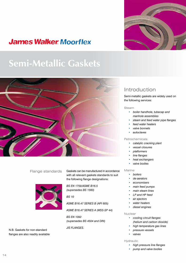
IntroductionSemi-metallic gaskets are widely used onthe following services:
Steam• boiler handhole, tubecap and
manhole assemblies• steam and feed water pipe flanges• feed water heaters• valve bonnets• autoclaves
Petrochemicals• catalytic cracking plant• vessel closures• platformers• line flanges• heat exchangers• valve bodies
Marine• boilers• de-aerators• economisers• main feed pumps• main steam lines• LP and HP feed• air ejectors• water heaters• diesel engines
Nuclear• cooling circuit flanges
(helium and carbon dioxide)• high temperature gas lines• pressure vessels• valves
Hydraulic• high pressure line flanges• pump and valve bodies
14
Gaskets can be manufactured in accordancewith all relevant gaskets standards to suitthe following flange designations:
BS EN 1759/ASME B16.5(supersedes BS 1560)
BS 10
ASME B16.47 SERIES B (API 605)
ASME B16.47 SERIES A (MSS-SP 44)
BS EN 1092(supersedes BS 4504 and DIN)
JIS FLANGES.N.B. Gaskets for non-standard
flanges are also readily available
Flange standards
Semi-Metallic Gaskets

15
Expanded GraphiteGasketsPlain or reinforced
Metaflex®
Spiral WoundGaskets
Metal JacketedGaskets
Metagraf
Semi-Metallic gasket types
Metakamm®
KammprofileGaskets
Metex
Metcom®
Multi-pressureGaskets

16
Gasket profilesMetaflex® gaskets aremanufactured from V-shapedmetal strips, spirally wound witha soft filler material. At the startand conclusion of the spiral form,several continuous turns of themetallic windings are securelywelded together.
The construction is capable ofinfinite variety as the number ofmetal plies in relation to filler pliescan be increased or decreased.The metal and filler material canbe varied to suit practically anyservice conditions.
The use of steel supporting ringson the inside or outside of thespiral wound portion (or both)permits the application ofMetaflex® gaskets to be extendedto flat or raised face flanges underhigh pressure.
Features• Fire-safe certified versions
available.
• Available in materials capableof withstanding temperaturesfrom the cryogenic range to atleast 1000°C.
• Can, in standard form, sealpressures up to 35MPa/350bar. Higher pressures (egclass 2500) can be consideredon request.
• Maintain a seal underconditions of thermal cyclingor vibration.
• Resist corrosion and leaveflange faces clean.
• Do not require ground orlapped flange faces.
• Are quick to fit and remove.
• Can often be used on bowedor pitted flanges.
• Offer good performance ondifficult dry gas or high vacuumapplications.
Type CBasic construction style. Suitable for tongueand groove, spigot and recess or flat faceand recess flanges.
Type SGAs Type C but fitted with an external ringwhich accurately centralises the sealingelement. In addition the ring provides extraradial strength and acts as a compressionstop. Generally used on raised face and flatface flanges.
Type SG/IRIdentical to the Type SG but also fitted withan inner ring to prevent damage to thegasket bore and inner windings. It also actsas a heat shield and corrosion barrier andimproves recovery characteristics andsealing performance. SG/IR is fire-safecertified to API 6FB.
Type C/IRIdentical to the Type C but fitted with theprotective inner ring which gives highpressure and temperature capabilities withimproved sealing performance. Used onspigot and recess flanges.
Metaflex®
Spiral wound gaskets
Type H and H/IWIn appearance these are identical toType C but specifically designed for thesealing of manholes, handholes, tubecapsand plugs in boilers and vessels. They canbe produced in a wide variety of shapes,the most common being circular, obround,square, oval and diamond. The H/IWincorporates a stainless steel wire on theinner surface which protects the innerwindings and reduces the risk of extrusionunder compression.
Type SG/IR Fire-SafeThis is a fire-safe certified version of SG/IRfor use in chemical plants. It comprises astainless steel inner support ring and windingstrip, and a carbon steel outer support ring.
It has PTFE filler in the inner sealing area,and graphite filler in the outer. PTFE enablesthe gasket to work with highly corrosive orhigh purity media. The graphite-filled areaprovides a secondary seal under emergencyfire conditions.
Metaflex® SG/IR Fire-Safe is fire-test certifiedto ANSI/API 607, Fifth edition, and ISO10497:2004. Third-party tests were carriedout by CEWAC/EID and witnessed by Lloyds.

17
Note: Due to the compression characteristics
of PTFE, full compression may not always
be achieved (eg, with SG/IR). If flange face
contact is essential then special clearances
can be considered.
Metaflex® manufacturing parametersThe standard Metaflex® Type SG and SG/IR gaskets are produced with a sealing elementthickness of 4.5mm and 3.0mm centring ring/inner rings. However, virtually all types areavailable in a variety of thicknesses from 2.5mm to 7.3mm nominal.
The following tables specify the various nominal and corresponding recommendedcompressed thicknesses together with maximum and minimum diameters for eachthickness.
Metaflex® gasket compressionMetaflex® gaskets must be compressed by a specific degree if maximum service potentialis to be realised.
* Whilst we do not generally recommend
above 3550mm, we have supplied type
SG/IR in excess of 5 metres diameter.
NOMINALTHICKNESS
COMPRESSEDTHICKNESS
2.5mm (0.098”) 1.9/2.1mm (0.075/0.85”)
3.2mm (0.125”) 2.4/2.6mm (0.095/0.105”)
4.5mm (0.175”) 3.2/3.45mm (0.125/0.135”)
7.3mm (0.285”) 5.00/5.25mm (0.197/0.207”)
Type TEThis type is identical to the Type C but isfitted with pass-partition bars for use on heatexchangers and vessels. The bars areusually manufactured like metal-jacketedgaskets but can also be solid metal facedwith graphite, PTFE or soft jointing material.
Type WG and WG/IRDesigned to suit the relatively narrow seatingspace on many heat exchangers by utilisinga spirally wound steel centring ring insteadof a solid ring. WG/IR has a solid inner ring.
Type WG/TE andWG/IR/TEIdentical to the WG profile but fitted withpartition bars.WG/IR/TE has an inner ring.
See page 26 for typical pass partition bar configurations.
SIZESNOMINAL THICKNESS
MINIMUMDIAMETER
MAXIMUMDIAMETER
2.5mm (0.098”) 22mm (7/8”) 300mm (12”)
3.2mm (0.125”) 10mm (3/8”) 760mm (30”)
4.5mm (0.175”) 10mm (3/8”) 1520mm (60”)
7.3mm (0.285”) 60mm (23/8”) 3550mm (140”)*

The most widely used material for windingmetal is SAE 316L and is usually used withcarbon steel or stainless steel flanges. Thestandard inner ring material is also SAE316L. It is normal practice for the inner ringand windings to be the same as, orcompatible with, the flange metal. Thispractice prevents corrosion and differentialexpansion problems. For very hightemperatures or highly corrosiveapplications, alternative materials may bechosen for both windings and inner rings.
PTFE inner rings can be supplied for highlycorrosive media.
As standard the centring rings are suppliedin carbon steel with an anti-corrosioncoating/treatment primarily to preventcorrosion in storage. The use of stainlesssteel for centring rings is quite commonwhere the external flange environmentconditions are corrosive to carbon steel, ortemperature conditions prohibit the use ofcarbon steel.
18
Metaflex® materials
* As standard supplied with a paint coating
to inhibit corrosion during storage. Other
protective coatings, eg. zinc plating with
a chrome passivate, are available on
request.
Hastelloy®, Incoloy® and Inconel® are registered trademarks of Special Metals Corporation. Monel® is a registered trademark of Haynes.
METAL WINDING STRIP
SAE 304
SAE 304L
SAE 316
SAE 316L
SAE 320
SAE 310
SAE 321
SAE 347
17-7 PH
ALLOY 20
MONEL® 400 & K500
NICKEL 200INCONEL® 600, 625 & X750
INCOLOY® 800 & 825
TITANIUM
HASTELLOY® B2 & C276
COPPER
ZIRCONIUM
DUPLEX
FILLER MATERIAL TEMPERATURE LIMITS
STANDARD PURITY GRAPHITE ‘SPG’
(98% MIN. PURITY) 500°C (Oxidising conditions)
HIGH PURITY GRAPHITE ‘HPG’ 600°C (Inert/reducing media)
(99.7% MIN. PURITY) 650°C (Steam)
NUCLEAR GRADE GRAPHITE(PMUC APPROVED)
PTFE 260°C
HIGH TEMPERATURE FILLER ‘HTF’ 1000°C
INNER & OUTER RING MATERIAL
CARBON STEEL* SAE 310 TITANIUM
SAE 304 SAE 321 HASTELLOY® B2 & C276
SAE 304L MONEL® 400 COPPER
SAE 316 NICKEL 200 ZIRCONIUM
SAE 316L INCONEL® 600,625 & X-750
DUPLEX
SAE 320 INCOLOY®
800 & 825PTFE (INNER RINGSONLY)

19
The Lolode gasket has been developed to
satisfy those requirements for maximum
sealing element compression, using the bolt
stress figure of 25,000 psi (172MPa) given
for certain material grades shown in the
ASME code. The expanded graphite (SPG)
filled Lolode, has the basic design and
properties of a standard Metaflex® spiral
wound gasket, but it has been carefully
engineered to enable compression down
to the guide ring under the limited load
provided by ASME B16.5 or BS 1560 class
150 or 300 flanges.
Lolode gaskets are available to ASME
B16.20 and BS 3381 dimensions to suit
class 150 and 300 flanges from 1/2” to 24”
nominal bore.
(Note that the large diameter flanges to ASME
B16.47 Series A and B do not suffer the
same poor ratio of gasket area to bolt area
as the smaller flanges such as 3” and 8”
class 150, and hence Lolode gaskets are
not required for these flanges).
The graph above shows a comparison of
the amount of compression obtained at a
given gasket stress for the Lolode version
compared to a standard Metaflex® SPG
filled spiral wound gasket. It can be seen
that the Lolode compresses down to the
nominal working thickness of 3.3mm at a
significantly lower level of stress than the
standard gasket.
Typicalload-compressioncomparison
Some methods of calculation of
the bolt load required to compress
conventional spiral wound
gaskets, result in figures which
appear to over-stress the standard
bolting of many ASME B16.5 class
150 and some 300 flanges.
Spiral wound gaskets have been
used successfully on these flange
classes for many years. However,
a lot more attention has recently
been paid to the amount of
compression that is actually
achieved when standard bolting
is employed. The replacement of
asbestos with expanded graphite
(SPG) filler, has improved this
situation by producing equivalent
sealing performance under lower
compressive forces, as well as
allowing greater compression for
a given bolt load.
It must be acknowledged that on
certain flanges, the amount of
available bolting may be
insufficient to achieve the degree
of compression normally
recommended by gasket
manufacturers, without exceeding
the recommended bolt stress
levels given in the flange design
codes. However, in practice,
gaskets have been found to be
capable of effecting a good
degree of sealing performance,
especially at the system pressures
associated with class 150 and 300
flanges, even though the gasket
may not be fully compressed to
the guide ring.
GASKET STRESS (MPa)
GA
SK
ET
THIC
KN
ES
S (
mm
)
0 20 40 60 80 100
33.23.43.63.8
44.24.44.64.8
5
StandardLolode
Metaflex® Lolode
Spiral wound gaskets

20
Kammprofile gaskets consist of ametal core with concentric serratedgrooves on each side and theaddition of a soft layer of sealingmaterial bonded to each face.Selection of the metallic corematerial and sealing layer materialsis dependent on the service duty.
The serrated metallic core is veryeffective for sealing in applicationswhere high temperatures, highpressures and fluctuatingconditions exist and can be usedwithout sealing layers, but there isa risk of flange damage, especiallyat high seating loads. The sealinglayers protect the flange surfacesfrom damage and also offerexcellent sealing properties whensupported by the serrated metalliccore.
Advantages• Can seal pressures up to
25MPa/250bar. Higher pressures(eg, Classes 1500 and 2500) canbe considered on request.
• Can withstand temperatures upto 1000°C — dependent on coreand layer materials used
• Can maintain effective sealingperformance in varyingtemperature and pressureconditions.
• Will not damage flange surfacesand can be removed easily.
• The serrated metallic core canbe re-used, subject to inspectionafter cleaning and re-layering.
• Can be made to suit existingarrangements, withoutmodification.
Type SGKParallel root core with integral centring ringfor correct gasket positioning within theflange bolt circle. Type SG is recommendedfor use on standard raised face and flat faceflanges.
Type LGKParallel root core with loose fitting centringring which reduces the possibility of damageto the core as a result of mechanical andthermal shock.
Type CCKAs above styles, except with a convex rootcore. This design ensures the highestcontact pressure is in the middle of theprofile and excellent flow of the soft sealinglayer into the flange surface.
Type CKParallel root core for use in confined locationincluding spigot and recess, tongue andgroove and recessed flange arrangements.
Gasket profiles
Type SGCKThis design can be an advantage whereflange rotation occurs and only a smallseating stress is required for the flanges tobecome tight.
Type LGCKGaskets of this design are particularlyeffective in fluctuating temperature and/orpressure conditions.
Metakamm®
Kammprofile gaskets

21
Gasket materials ManufacturingparametersNormally supplied with a 3.0mm or 4.0mmthick core and covering layers 0.5mm thick,but can also be supplied in otherthicknesses.
Diameters from 10mm NB upwards can bemanufactured and the size limitation foreach type of Metakamm® gasket is asfollows:
Type CK & CCK up to 5000mm diameter
Type SGK & SGCK up to 2000mm diameter
Type LGK & LGCK up to 2000mm diameter
Type TE up to 5000mm diameter
Type EF up to 5000mm diameter
For heat exchanger applications see page26 for typical pass partition bar configuration.
Metakamm®
Easi-fitIn order to facilitate easier fittingand to reduce material andmachining costs, largerMetakamm® gaskets can besupplied as Type EF gaskets witheither two or four locating lugs.These lugs aid fitting, as aminimum number of flange boltsneed be removed for the gasketto be easily, but accuratelypositioned.
Metakamm® gaskets are available to order in a wide variety of component materials.
STAINLESSSTEELS
COREMATERIAL
SOFT FACINGMATERIAL
TEMPERATURELIMITS
SAE 304SAE 304LSAE 316SAE 316LSAE 320SAE 321SAE 347SAE 310
STANDARD PURITYGRAPHITE‘SPG’ (98% min. purity)HIGH PURITY GRAPHITE‘HPG’ (99.7% min. purity)
500°C(oxidising conditions)600°C(inert/reducing media)650°C (steam)
Monel® 400 & K500Nickel 200
PTFE 260°C
Inconel® 600, 625 & X750Incoloy® 800 & 825
HIGH TEMPERATUREFILLER ’HTF’
1000°C
Hastelloy® HB2 & C276CopperDuplex
SOFT METALS: SILVER,ALUMINIUM, etc.

22
Standard gasket profile
150lb
300lb, 400lb
600lb
GRAPHITE FACINGS
LOOSE GUIDE RING
CORE RING
“One size fits all”In the most popular piping classes
(ASME 150, 300, 600 or DIN PN10-
100) only ONE gasket is required
for each nominal bore size –1/2” through to 24” and 10mm NB
to 600mm NB.
Uses well proven Kammprofile
gasket technology with specially
designed sealing elements and
location rings.
The cost effectiveKammprofile• Kammprofile consistency
& performance.
• Self locating.
• Reduces & simplifies inventory.
• Minimises ‘out of stock’ risk.
• Reduces ‘lifetime’ cost.
• Re-usable ‘clip in’ outer guides.
• Re-usable sealing elements -with new facings.
• Ex stock availability for SAE316L cores with graphite.
• Full range of materials available.
• Other sizes on application.
How to order• Quantity.
• Nominal bore & pressure rating,eg 2” 150-600.
• Flange description,eg ASME, DIN.
• Material combination,eg SAE 316L/graphite.
Metakamm®
Multifit gaskets

23
Spiral wound & Kammprofile gasketsChemical suitability guide
Notation:A Fully resistant (less than 0.009mm penetration per month)B Satisfactory (0.009mm - 0.09mm per month)C Fairly resistant (0.09mm - 0.025mm per month)D Slightly resistant (0.25mm - 0.9mm per month)E Non-resistant (over 0.9mm per month)O Insufficient data available
Where chemical compatibility is not indicated, or a chemical is notlisted, please consult our technical services team for arecommendation to be made.
Filler and facing materials:EXPANDEDGRAPHITE:
See details for Supagraph® Plain Standard Sheet. (High temperature, oxidation-inhibitedgraphite is also available – please request details.)
HTF (HIGHTEMPERATUREFILLER):
When used with suitable winding steel grades, this material resists the majority ofcommon media including; hot oil, fuels, acids, alcohols and esters. It should NOT beused with sulphuric, phosphoric, hydrofluoric or other strong mineral acids.
PTFE: This material is chemically inert to most media, with a few exceptions as follows:-• It offers only fair resistance to: ammonium hydroxide, bromine, chromic acid,hydroboric acid, hydrochloric acid, hydrocyanic acid, nitric acid (0-50%), phenol andsodium hydroxide.• It should NOT be used with: fluorosilicic acid, hydrofluoric acid, hydrogen sulphidesolution or sodium silicate.
SAE
304L
, 321
, 347
SAE
316,
316
L
NICK
EL 2
00
MON
EL 4
00
INCO
NEL
625
STEAM A A A A ASTEAM CONDENSATE A A A A AWATER A A A A AAIR A A A A AACETIC ACID (50% @ boiling) C B B A BACETIC ANHYDRIDE (boiling) A A A A AACETONE (boiling) A A A A AALUMINIUM CHLORIDE (20°C) D C B B CAMMONIA LIQUOR (boiling) A A C C AAMMONIUM CHLORIDE (50% boiling) B A A A BAMMONIUM NITRATE (boiling) A A E E BANILINE (concentrated @ 20°C) A A A A ABARIUM CHLORIDE (boiling) B A B A BCHROMIUM PLATING BATH (20°C) A A C C ACITRIC ACID (15% boiling) B A B A ACOPPER SULPHATE (saturated/boiling) A A C C CCREOSOTE/TAR (hot) A A A A AETHER (20°C) A A A A AETHYL ALCOHOL (boiling) A A A A AETHYL CHLORIDE (20°C) A A A A AETHYLENE CHLORIDE (20°C) A A A A AFERRIC CHLORIDE (1% @ 20°C) B A B C CFLUORINE (20°C) E E A A AFORMALDEHYDE (Formalin 40%) B A A A AFORMIC ACID (5% @ 65°C, still) B A A A AFUEL OIL (hot) A A B B AFUEL OIL (+ sulphuric acid) C B B B BHYDROCHLORIC ACID (20°C) E E B B CHYDROFLUOSILICIC ACID (20°C) E D A A BHYDROGEN PEROXIDE (boiling) B A O O OHYDROGEN SULPHIDE (wet) B A A A AKEROSENE A A A A ALACTIC ACID (10% @ 65°C) C B B B BLINSEED OIL (20°C) A A A A AMAGNESIUM CHLORIDE (5% hot) C B A A AMAGNESIUM SULPHATE (hot) A A A A A
SAE
304L
, 321
, 347
SAE
316,
316
L
NICK
EL 2
00
MON
EL 4
00
INCO
NEL
625
METHYLALCOHOL (65°C) C B A A A
NAPHTHA (20°C) A A A A A
NICKEL CHLORIDE SOLUTION (20°C) A A B B B
NICKEL SULPHATE (hot/cold) A A A A A
NITRIC ACID (50% @ 20°C) A A E E A
NITRIC ACID (65% @ boiling) B B E E D
OIL - CRUDE (hot/cold) A A A A A
OIL - VEG/MINERAL (hot/cold) A A A A A
OXALIC ACID (10% boiling) D C B A B
PHENOL A A A A A
PHOSPHORIC ACID (10% @ 20°C) C B B B B
PICRIC ACID (70%) A A O O O
POTASSIUM BICHROMATE (20°C) A A A A A
POTASSIUM CHLORIDE (5% boiling) A A A A A
POTASSIUM HYDROXIDE (50% boiling) B A A A A
POTASSIUM NITRATE (5% hot) A A A A A
POTASSIUM SULPHATE (5% hot) A A A A A
POTASSIUM SULPHIDE (salt) A A A A A
SEA WATER A A A A A
SEWAGE A A A A A
SODIUM CARBONATE (5% @ 65°C) A A A A A
SODIUM CHLORIDE (saturated/boiling) B A A A A
SODIUM HYDROXIDE A A A A A
SODIUM HYPOCHLORITE (5% still) B A C C C
SODIUM NITRATE (fused) C B A B A
SODIUM SULPHATE (20°C) A A A A A
SULPHUR DIOXIDE (moist 20°C) B A D C C
SULPHUR (wet) B A B B A
SULPHURIC ACID (10% @ 20°C) C B B A C
SULPHURIC ACID (fuming @ 20°C) C B C B B
SULPHUROUS ACID (saturated 190°C) C B E E E
TANNIC ACID (65°C) A A A A A
TRICHLORACETIC ACID (20°C) E E B B B
ZINC CHLORIDE (5% boiling) B B B B B
ZINC SULPHATE (25% boiling) A A A A A
Due to the complexity of making a recommendation for any given duty, this section on chemical compatibilityis intended only as a guide. The possible effect of elevated temperatures should be considered whendetermining the compatibility of these products with a chemical. If necessary, please contact our technicalservices team for assistance.
METALLICCOMPONENT
METALLICCOMPONENT

24
Integral barsThis method of construction ensures thatthe gaskets have uniform hardness aroundthe main periphery of the primary seal andalong the pass partition bars. As there is asolid join between the bars and the maingasket, the construction is more robust. Thisconstruction is recommended for the sealingof hazardous fluids. We recommend thatthis style has at least a 10mm radius at allintersections, this maintains a continuousmetal overlap, which prevents splitting ofthe metal.
Welded barsThis method of construction has distinctcommercial advantages as it allows fullmaterial utilisation. Welding is carried outusing methods which ensure that metalhardening is minimised.
Flange nubbinsFlange nubbins are often used to increasestress and in such cases, care must betaken to install the gaskets with the seamedface on the opposite side.
Metal jacketed gaskets are frequently required with pass partition bars, which may bemanufactured by two methods, either with ‘integral’ bars or with bars welded onto themain gasket. Both methods have advantages and we are able to supply to either methodof construction.
These gaskets are speciallydesigned and widely used for heatexchangers, autoclaves, columns,pressure vessels, flue stacks,boilers, gas mains, valve bonnets,pumps and similar services.
The gaskets are manufacturedfrom a soft, pliable filler coresurrounded by a metal jacket,chemically and thermally resistantto the working conditions, whichmay totally or partially enclose thefiller.
The majority of these types ofgasket are supplied in circularform but can be manufactured toother shapes to suit individualrequirements. The method ofmanufacture enables gaskets tobe produced with almost no sizelimitations. They are produced indifferent styles to API, ASME, andinternational/European standards.
The gasket seam should be on the oppositeside to any flange nubbin(s)
Metaljacketed gaskets

25
M123Double jacketedSoft filler – totally enclosed
M124Single jacketedSoft filler – totally enclosed
M129Double jacketedMetal filler – corrugated
M120Single jacketedSoft filler – open type
Metal jacketedgasket styles
M126Double jacketedSoft filler – corrugated
M130Single jacketedSoft filler – open edge outside
M131Double jacketedSoft filler – open edge outside
Metal jacketedgasket materialsMetal JacketMetals are only used in the annealedcondition and limit the hardness of the metalin line with international standards.
FillersSelection of the correct filler is importantand as standard we use a soft non-asbestosfiller. This material is constructed frominorganic fibre and inert fillers, suitablybonded, which produces a material havingvery similar characteristics to those ofasbestos millboard. A data sheet on thismaterial is available on request. Alternativefillers include expanded graphite, PTFE,and compressed non-asbestos fibre.
MAXIMUM HARDNESSBRINELL
SOFT IRON 90LOW CARBON STEEL 120SAE 304 STAINLESS STEEL 160SAE 316 STAINLESS STEEL 160SAE 321 STAINLESS STEEL 160TITANIUMBRASSCOPPERALUMINIUMF5 ALLOY STEEL 130SAE 410 (11/13% CHROME) 170NICKELMONEL®
INCONEL®

Metal Jacketed GasketsKammprofile GasketsSpiral Wound Gaskets
26
Heat Exchanger gasket shapes
Typical pass partition bar configurations
21
27
58
64
20
14
26
13
19
25
68
12
18
24
30
67
11
17
23
29
66
10
16
22
28
65
15
6362616059
5756555453
33
39
45
51
32
38
44
50
37
43
49
36
42
48
35
41
47
31
34
40
46
52

27
Metagraf/MetexgasketsMetagraf has a corrugated metal core,
normally stainless steel, with Supagraf®
expanded graphite facings. Available as
Metagraf PL with a wide chemical
compatibility for standard pipeline duties,
and Metagraf HX for sealing heat
exchangers.
Metex is a robust gasket comprising a flat
metal core, (eg. 3mm thick stainless or
carbon steel) with Supagraf® expanded
graphite facings. It is typically used for large
diameter gaskets, as well as heat exchanger
duties where seating space is limited.
Temperature limits
Oxidising atmosphere -200°C to +400°C
Steam +650°C Maximum
How supplied
Metagraf PL To suit ASME class
150/300 as well as
DIN flanges
HX and Metex Custom made to
order
Metagraf Metex
How to order• If material is known
1 Quantity2 Material3 Thickness4 Nominal bore and flange
specification or sizes
• If unsure of material, state allabove plus full operatingconditions, eg. temperature,pressure, media.
Corrusafe FS (fire-safe)gasketThis fire-safe certified gasket comprises
corrugated support rings of stainless steel with
dual material sealing faces.
The inner sealing envelope of PTFE is chemically
inert to eliminate the risk of product
contamination. The outer elements of graphite
provide a secondary seal under fire conditions.
Corrusafe FS is fire-test certified to ANSI/API 607,
Fifth edition, and ISO 10497:2004. Third-party
tests were carried out by CEWAC/EID and
witnessed by Lloyds.
It is recommended for flange sealing in aggressive
environments where it is essential to prevent
leakage of flammable, corrosive or toxic media
under emergency fire conditions. Applications
include pipelines and pressure vessels on steam,
petrochemical, nuclear, marine and hydraulic
plant; also heat exchangers.
Operating limits
Max temperature (continuous): +260°C
Max operating pressure: 5MPa/50bar
How supplied
Sizes: DN10 to DN1200, pressure ratings PN10
to PN40; 1/2” to 48” for ASME flange Classes 150
to 600.

28
Metcom®
GasketsThese are another variation of a graphitegasket, consisting of a thin corrugated sheetsteel joint with pairs of grooves pressedconcentrically from either side. The groovesare relatively narrow (approx. 6mm) and twoadjacent grooves are filled with a bead ofgraphite tape, 3mm wide. When compressedbetween flanges, there is a reactive forcefrom the metal corrugations which combinewith the graphite enhances the sealingcapability. The corrugations also assist inretaining the graphite.
This type of gasket is more robust and easierto fit than a sheet graphite cut joint. It hasthe advantage of being thinner than a spiralwound gasket and therefore can be utilisedto replace thin sheet gaskets in thoseinstances where use of spiral wound jointscould disrupt pipe alignment due to theiradditional thickness.
The gasket can be safely tightened to highlevels of bolt stress.
Advantages• One size fits 150 through to 2500lb
flanges.
• Gasket is self locating.
• Once torqued, rarely needs re-tightening.
AvailabilityMultifit1/2” to 12” class 150-2500(equivalent DIN sizes up to 300mm NB)
Inside bolt circle1/2” to 24” class 150-2500(individual class inside bolt circle joint rings).
Other sizes on application.
The Metcom® is designed with a profiledmetal retainer ring so that a single gasketfits all flanges within a pipe size. The drawingshows how a Metcom can be fitted to thebolt circles on all flange ratings from 150lbto 2500lb.
Sealing ringsFlexible graphite has been widely recognisedas the best material, which combines thebest thermal as well as chemical stability(nuclear grade available). PTFE is availablein those applications where flexible graphiteis not suitable.
Metcom®
Materials
150lb
300lb, 400lb, 600lb
900lb, 1500lb
2500lb
Metcom®
Multifit configurationMETAL CORE SAE 304, SAE316L
(other metals availablefor specific applications)
SEALINGMATERIAL
GRAPHITESTANDARD(PTFE OPTIONAL)THICKNESS0.35mm TO 0.5mmDENSITY0.7gm/cc minimum
NOMINALOVERALLTHICKNESS
1.5mm
COMPRESSEDTHICKNESS
0.5mm
PRESSURERATINGS
VACUUM TO CLASS2500 DEPENDING ONTEMPERATURE
TEMPERATURECAPABILITIES
CRYOGENICTO 500°C OXIDISING:TO 650°C STEAM

IntroductionOrigin and applicationThe sealing of well-head valves and fittingsin exploration and production areas of theoil and natural gas industry has constantlypresented a higher pressure requirementthan has been necessary in most othermajor manufacturing processes.
To meet this requirement, the AmericanPetroleum Institute developed ring jointflanges and their accompanying gasketrequirement and issued standards covering“general use” and “oil field use”. These twocategories are now covered by ASME andAPI standards respectively, of similardimension but differently rated in materialstrength to allow the API flange to operateat a higher working pressure.
The solid metal gasket provides an excellentmechanical joint and has almost universalacceptance in the oil, petroleum andchemical processing industries where highmechanical and thermal performance isrequired.
Typical uses• High pressure oil field drilling and
production equipment.
• Pressure vessels.
• Pipeline valves.
• Gas and chemical plants.
Under its Moorside® brand James WalkerMoorflex is a leading manufacturer of thecomplete range of solid metal ring jointgaskets. The gaskets are manufactured toAPI 6A and ASME B16 20 standards and tocustomers’ own specifications.
29
Metallic Gaskets
Top performanceunder extreme conditions
James Walker Moorflex’s precision
machining creates a product with the high
performance standards needed for today’s
extremely demanding applications. Moorflex
uses only the best forged metals (no welded
rings) which undergo a stringent machining
process to ensure that close tolerances and
smooth contact surfaces are rigidly
maintained.
Quality is guaranteed by a strict series of
tests and process quality control, and
Moorflex’s final inspection assures total
compliance with customer specifications.
Hence, engineers confidently continue to
specify Moorflex gaskets for their
requirements in both original equipment
and replacements.

30
MaterialsGasket metal should be selected to suit theservice conditions and should be of ahardness lower than the flange metal. AtMoorflex, the annealing process of the metaland the machining is carefully controlled tokeep the hardness of the gasket below themaximum allowable, to ensure correct flowand sealing without damage to the flangesurfaces.
Checks carried out during manufactureensure that the hardness of the finishedproduct does not exceed the figures statedbelow.
The principal types of material are:
Other stainless and super alloy steels,
Duplex, Monel®, Inconel®, Incoloy®. Nickel
and other materials are available. Based on
almost 50 years of experience, Moorflex has
established specifications to ensure gasket
suitability. Certification and compliance with
NACE MR0175 are standard features.
Identification and traceability
For convenience in ordering, numbers are
assigned to gaskets and prefixed by the
letter ‘R’, ‘RX’ or ‘BX’, followed by the material
identification. Marking is effected so as not
to injure the contact faces, nor to harmfully
distort the gasket. Moorflex uses only low
stress DOT stamps approved to NACE
standards in order to ensure that stresses
are not introduced into the gasket.
All non-API gaskets are typically marked
Moorside R45 S316. Gaskets complying to
API Standard 6A are additionally marked
with API Monogram Licence No., Product
Specification Level 4 and date of
manufacture. (It is standard procedure for
Moorflex to supply API 6A gaskets to PSL4).
All API gaskets are typically marked:
Moorside 6A-0038 R45 S316-4 12/2001
Traceability of material and constant
monitoring of manufacture are essential for
effective quality control. All Moorside ring
joint gaskets carry a Material Reference
Number, which directly relates to the batch
of material from which it was manufactured.
The MRN number is applied to the gasket
in the same way as the identification marks.
This reference is included in material
certificates, thus ensuring full traceability of
supply.
Moorside or M denotes James Walker
Moorflex trademark.
Moorside®
Metal ring joint gaskets
Protection
Soft iron and low carbon steel ringjoint gaskets to API Standard 6Aare supplied with zinc plating to0.0002” - 0.0005” thick unlessotherwise specified. Other platingsare also available if preferred.Unplated rings are treated with arust preventative fluid.
During storage and handling it isvery important that the matingfaces (the oval radius or thechamfered face) are not damagedas this can lead to leakage whenthe ring joint is used in itsparticular application.
To afford the maximum degree ofprotection, Moorflex offers as anextra feature individual vacuumpackaging. Gaskets are vacuumpacked using a strong clear filmonto a stout backing board. Thisstyle of packaging ensures fullprotection of the gasket, whilstallowing visual inspection of itscondition and marking.
How to orderThe styles described aremanufactured as standard andare available ex-stock or to shortlead-times. When ordering pleasesubmit the following data:
• Gasket standard.• Relevant ring number or
nominal pipe size with rating.• Material required.• Oval or octagonal shape for
Style ‘R’ gaskets.• Quantity and required delivery.
METAL MAXIMUMHARDNESSIDENTIFICATIONROCKWELL B
SOFT IRON 56 (90 BHN) D
LOW CARBONSTEEL
68 (120 BHN) S
F5ALLOY STEEL(4/6% Cr, 1/2% Mo)
72 (130 BHN) F5
SAE 410ALLOY STEEL(11/13% Cr)
86 (170 BHN) S410
SAE 304STAINLESS STEEL
83 (160 BHN) S304
SAE 304LSTAINLESS STEEL
83 (160 BHN) S304L
SAE 316STAINLESS STEEL
83 (160 BHN) S316
SAE 316LSTAINLESS STEEL
83 (160 BHN) S316L
SAE 347STAINLESS STEEL
83 (160 BHN) S347
SAE 321STAINLESS STEEL
83 (160 BHN) S321
SAE 825NICKEL ALLOY
93 (200 BHN) 825
31
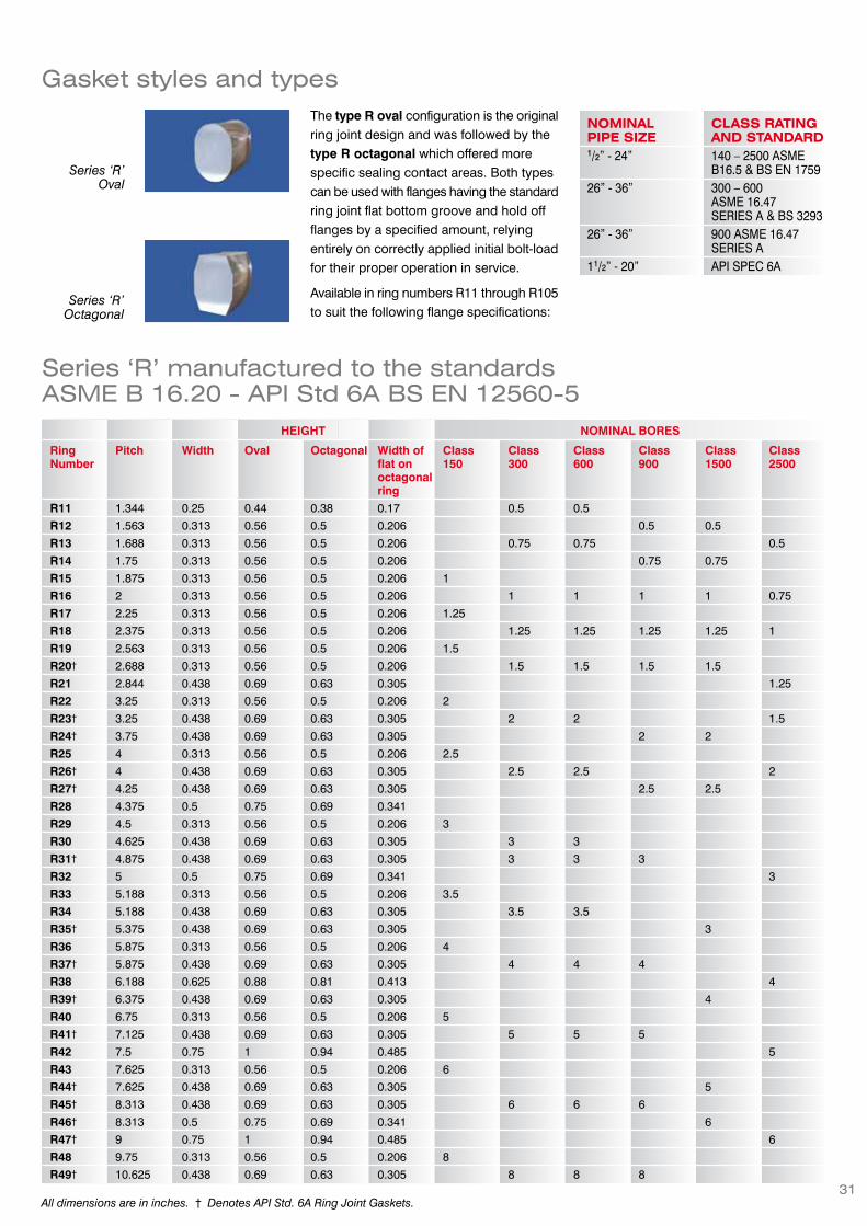
The type R oval configuration is the originalring joint design and was followed by thetype R octagonal which offered morespecific sealing contact areas. Both typescan be used with flanges having the standardring joint flat bottom groove and hold offflanges by a specified amount, relyingentirely on correctly applied initial bolt-loadfor their proper operation in service.
Available in ring numbers R11 through R105to suit the following flange specifications:
NOMINALPIPE SIZE
CLASS RATINGAND STANDARD
1/2” - 24” 140 – 2500 ASMEB16.5 & BS EN 1759
26” - 36” 300 – 600ASME 16.47SERIES A & BS 3293
26” - 36” 900 ASME 16.47SERIES A
11/2” - 20” API SPEC 6A
Series ‘R’Oval
Series ‘R’Octagonal
Series ‘R’ manufactured to the standardsASME B 16.20 - API Std 6A BS EN 12560-5
HEIGHT NOMINAL BORES
RingNumber
Pitch Width Oval Octagonal Width offlat onoctagonalring
Class150
Class300
Class600
Class900
Class1500
Class2500
R11 1.344 0.25 0.44 0.38 0.17 0.5 0.5
R12 1.563 0.313 0.56 0.5 0.206 0.5 0.5
R13 1.688 0.313 0.56 0.5 0.206 0.75 0.75 0.5
R14 1.75 0.313 0.56 0.5 0.206 0.75 0.75
R15 1.875 0.313 0.56 0.5 0.206 1
R16 2 0.313 0.56 0.5 0.206 1 1 1 1 0.75
R17 2.25 0.313 0.56 0.5 0.206 1.25
R18 2.375 0.313 0.56 0.5 0.206 1.25 1.25 1.25 1.25 1
R19 2.563 0.313 0.56 0.5 0.206 1.5
R20† 2.688 0.313 0.56 0.5 0.206 1.5 1.5 1.5 1.5
R21 2.844 0.438 0.69 0.63 0.305 1.25
R22 3.25 0.313 0.56 0.5 0.206 2
R23† 3.25 0.438 0.69 0.63 0.305 2 2 1.5
R24† 3.75 0.438 0.69 0.63 0.305 2 2
R25 4 0.313 0.56 0.5 0.206 2.5
R26† 4 0.438 0.69 0.63 0.305 2.5 2.5 2
R27† 4.25 0.438 0.69 0.63 0.305 2.5 2.5
R28 4.375 0.5 0.75 0.69 0.341
R29 4.5 0.313 0.56 0.5 0.206 3
R30 4.625 0.438 0.69 0.63 0.305 3 3
R31† 4.875 0.438 0.69 0.63 0.305 3 3 3
R32 5 0.5 0.75 0.69 0.341 3
R33 5.188 0.313 0.56 0.5 0.206 3.5
R34 5.188 0.438 0.69 0.63 0.305 3.5 3.5
R35† 5.375 0.438 0.69 0.63 0.305 3
R36 5.875 0.313 0.56 0.5 0.206 4
R37† 5.875 0.438 0.69 0.63 0.305 4 4 4
R38 6.188 0.625 0.88 0.81 0.413 4
R39† 6.375 0.438 0.69 0.63 0.305 4
R40 6.75 0.313 0.56 0.5 0.206 5
R41† 7.125 0.438 0.69 0.63 0.305 5 5 5
R42 7.5 0.75 1 0.94 0.485 5
R43 7.625 0.313 0.56 0.5 0.206 6
R44† 7.625 0.438 0.69 0.63 0.305 5
R45† 8.313 0.438 0.69 0.63 0.305 6 6 6
R46† 8.313 0.5 0.75 0.69 0.341 6
R47† 9 0.75 1 0.94 0.485 6
R48 9.75 0.313 0.56 0.5 0.206 8
R49† 10.625 0.438 0.69 0.63 0.305 8 8 8
Gasket styles and types
All dimensions are in inches. † Denotes API Std. 6A Ring Joint Gaskets.

32
HEIGHT NOMINAL BORES
RingNumber
Pitch Width Oval Octagonal Width offlat onoctagonalring
Class150
Class300
Class600
Class900
Class1500
Class2500
R50† 10.625 0.625 0.88 0.81 0.413 8R51 11 0.875 1.13 1.06 0.583 8R52 12 0.313 0.56 0.5 0.206 10R53† 12.75 0.438 0.69 0.63 0.305 10 10 10R54† 12.75 0.625 0.88 0.81 0.413 10R55 13.5 1.125 1.44 1.38 0.78 10R56 15 0.313 0.56 0.5 0.206 12R57† 15 0.438 0.69 0.63 0.305 12 12 12R58 15 0.875 1.13 1.06 0.583 12R59 15.625 0.313 0.56 0.5 0.206 14R60 16 1.25 1.56 1.5 0.879 12R61 16.5 0.438 0.69 0.63 0.305 14 14R62 16.5 0.625 0.88 0.81 0.413 14R63† 16.5 1 1.31 1.25 0.681 14R64 17.875 0.313 0.56 0.5 0.206 16R65† 18.5 0.438 0.69 0.63 0.305 16 16R66† 18.5 0.625 0.88 0.81 0.416 16R67 18.5 1.125 1.44 1.38 0.78 16R68 20.375 0.313 0.56 0.5 0.206 18R69† 21 0.438 0.69 0.63 0.305 18 18R70† 21 0.75 1 0.94 0.485 18R71 21 1.125 1.44 1.38 0.78 18R72 22 0.313 0.56 0.5 0.206 20R73† 23 0.5 0.75 0.69 0.641 20 20R74† 23 0.75 1 0.94 0.485 20R75 23 1.25 1.56 1.5 0.879 20R76 26.5 0.313 0.56 0.5 0.206 24R77 27.25 0.625 0.88 0.81 0.413 24 24R78 27.25 1 1.31 1.25 0.681 24R79 27.25 1.375 1.75 1.63 0.977 24R80 24.25 0.313 0.5 0.206 22R81 25 0.563 0.75 0.377 22 22R82† 2.25 0.438 0.63 0.305R84† 2.5 0.438 0.63 0.305R85† 3.125 0.5 0.69 0.341R86† 3.563 0.625 0.81 0.413R87† 3.938 0.625 0.81 0.413R88† 4.875 0.75 0.94 0.485R89† 4.5 0.75 0.94 0.485R90† 6.125 0.875 1.06 0.583R91† 10.25 1.25 1.5 0.879R92 9 0.438 0.69 0.63 0.305R93 29.5 0.75 0.94 0.485 26 26R94 31.5 0.75 0.94 0.485 28 28R95 33.75 0.75 0.94 0.485 30 30R96 36 0.875 1.06 0.583 32 32R97 38 0.875 1.06 0.583 34 34R98 40.25 0.875 1.06 0.583 36 36R99† 9.25 0.438 0.63 0.305R100 29.5 1.125 1.38 0.78 26R101 31.5 1.25 1.5 0.879 28R102 33.75 1.25 1.5 0.879 30R103 36 1.25 1.5 0.879 32R104 38 1.375 1.63 0.977 34R105 40.25 1.375 1.63 0.977 36
All dimensions are in inches. † Denotes API Std. 6A Ring Joint Gaskets.

33
As well-head pressures increased to69MPa/690bar (10,000psi) and beyond,flanges designed with type ‘R’ oval oroctagonal rings became excessively heavy,requiring impracticably large bolts to perform
the double duty of holding pressure whilekeeping the gasket compact.
The solution to this problem was found inhigher strength materials and thedevelopment of the ‘BX’ and ‘RX’ series jointwhich are pressure energised. (The higherthe contained pressure, the tighter the seal).
The ‘RX’ Style Ring Joint has a self-sealingaction. The outside bevels of the ring makethe initial contact with the groove as theflanges are brought together, thus pre-
loading the gasket against the sides of thegroove. Internal pressure during serviceincreases this loading and, therefore, thegasket’s sealing performance.
Available in ring numbers RX20 throughRX215 to suit the following flangespecifications:
NOMINALPIPE SIZE
CLASS RATINGAND STANDARD
11/2” - 20” 720 - 5,000 API 6BFlanges
Series ‘RX’ manufactured to the standardsASME B 16.20 - API Std 6A
GASKET DIMENSIONS PRESSURE CLASS RATING
Ring No. I/D O/D Height 720-9602000
2900 3000 5000
Nominal Pipe SizeRX 20 2.313 3.000 0.750 1.1/2 1.1/2RX 23 2.672 3.672 1 2RX 24 3.234 4.172 1 2 2RX 25 3.625 4.313 0.750 3.1/8RX 26 3.469 4.406 1 2.1/2RX 27 3.719 4.656 1 2.1/2 2.1/2RX 31 4.359 5.297 1 3 3RX 35 4.859 5.797 1 3RX 37 5.359 6.297 1 4 4RX 39 5.859 6.797 1 4RX 41 6.609 7.547 1 5 5RX 44 7.109 8.047 1 5RX 45 7.797 8.734 1 6 6RX 46 7.688 8.750 1.125 6RX 47 8.094 9.656 1.625 8RX 49 10.109 11.047 1 8 8RX 50 9.844 11.156 1.250 8RX 53 12.234 13.172 1 10 10RX 54 11.969 13.281 1.250 10RX 57 14.484 15.422 1 12 12RX 63 15.266 17.391 2 14RX 65 17.984 18.922 1 16RX 66 17.719 19.031 1.250 16RX 69 20.484 21.422 1 18RX 70 20.094 21.656 1.625 18RX 73 22.406 23.469 1.250 20RX 74 22.094 23.656 1.625 20RX 82 1.734 2.672 1 1RX 84 1.984 2.922 1 1.1/2RX 85 2.484 3.547 1 2RX 86 2.891 4.078 1.125 2.1/2RX 87 3.266 4.453 1.125 3RX 88 4.109 5.484 1.250 4RX 89 3.672 5.109 1.250 3.1/2RX 90 5.188 6.875 1.750 5RX 91 8.922 11.297 1.781 10RX 99 8.734 9.672 1 8 8RX 201 1.573 2.026 0.445 1.3/8RX 205 2.016 2.453 0.437 1.13/16RX 210 3.094 3.844 0.750 2.9/16RX 215 4.609 5.547 1 4 .1/16
Series ‘RX’
All dimensions are in inches. † Denotes API Std. 6A Ring Joint Gaskets.

34
Series ‘BX’ manufactured to the standardsASME B 16.20 - API Std 6A
Designed to API specifications for use withgrooved flanges on special applicationsinvolving high pressure up to138MPa/1380bar (20,000psi) the ‘BX’ seriesis available in ring numbers BX 150 throughBX 303 to suit the following flangespecifications:
Style ‘BX’ Ring Joint Gaskets can only beused with special ‘BX’ grooves and are notinterchangeable with the Style ‘RX’ series.
NOMINALPIPE SIZE
CLASS RATINGAND STANDARD
111/16” - 211/4” 5,000-20,000API 6 BX Flanges Series ‘BX’
GASKET DIMENSIONS PRESSURE CLASS RATING
Ring No. I/D O/D Height 2000 3000 5000 10000 15000 20000
Nominal Pipe Size
BX 150 2.110 2.842 0.366 1.11/16 1.11/16
BX 151 2.250 3.008 0.379 1.13/16 1.13/16
BX 152 2.528 3.334 0.403 2.1/16 2.1/16 2.1/16
BX 153 3.078 3.974 0.448 2.9/16 2.9/16 2.9/16
BX 154 3.624 4.600 0.488 3.1/16 3.1/16 3.1/16
BX 155 4.705 5.825 0.560 4.1/16 4.1/16 4.1/16
BX 156 7.901 9.637 0.733 7.1/16 7.1/16 7.1/16
BX 157 9.941 11.593 0.826 9 9
BX 158 12.038 13.860 0.911 11 11 11
BX 159 14.776 16.800 1.012 13.5/8 13.5/8 13.5/8
BX 160 14.768 15.850 0.938 13.5/8
BX 161 18.071 19.347 1.105 16.3/4
BX 162 17.600 18.720 0.560 16.3/4 16.3/4 16.3/4
BX 163 20.528 21.896 1.185 18.3/4
BX 164 20.527 22.463 1.185 18.3/4 18.3/4
BX 165 23.139 24.595 1.261 21.1/4
BX 166 23.140 25.198 1.261 21.1/4
BX 167 28.864 29.896 1.412 26.3/4
BX 168 28.864 30.128 1.412 26.3/4
BX 169 5.813 6.831 0.624 5.1/8
BX 170 7.464 8.584 0.560 6.5/8 6.5/8
BX 171 9.409 10.529 0.560 8.9/16 8.9/16
BX 172 11.993 13.113 0.560 11.5/32 11.5/32
BX 303 32.237 33.573 1.494 30 30
All dimensions are in inches.

Transition ringsDescriptionTransition rings are used for sealing ringtype joints in which the mating flanges havedifferent ring groove diameters. These canbe made in any standard ring joint gasketmetal. Popular transition combinations areR23/R24, R26/R27, R49/R50 and R65/R66.
Other sizes made with oval or octagonalfacings are available to order. When orderingplease specify which cross-section ispreferred.
PTFE inner ringsDescriptionMoorflex PTFE inner rings are designed tooccupy the cavity between the flange boreand ring joint, fitting closely to the internaldiameter of the ring joint and having a smallclearance from the bore of the flange.
The use of these components ensures thatthe effects of discontinuity in pipe boresmoothness are considerably reduced.Turbulence of flow, accumulation of sedimentwhich will not be removed by normaldescaling and pig cleaning equipment, andthe possibility of corrosion or erosion offlange and joint surfaces are minimised.
Inserts for type ‘R’ joints have a coarsemachined finish, whilst type ‘RX’ inserts havea deeper grooved profile to control spreadunder compression within the clearanceallowance from the flange bore. Ports permitpressure access to the ring joint to aidventing in the case of sudden systemdecompression.
MaterialMoorflex PTFE inner rings for metallic ringjoint gaskets are manufactured from purePTFE which is chemically inert to nearly allsubstances. Only molten alkali metals,fluorine and some fluorine compounds athigh temperatures and pressures have beenknown to affect it. PTFE is also suitable fora wide range of temperatures from -200°Cto +250°C.
How to orderInserts are available to suit all metallic ringjoint gaskets, and may be ordered bysupplying the same information specifiedfor metal ring gaskets.
Flange protectorsDescriptionOur flange protectors are designed to protectstuds and gaskets on raised face and ringtype joint flanges from atmospheric corrosionencountered in chemical plants, refineries,gas plants, offshore platforms, onshore oilfields, ships, paper mills and undergroundpipelines.
MaterialsThey are made from stainless steel with abonded, closed-cell neoprene sponge liner,and stainless steel grease fittings. Packedwith corrosion inhibitor grease, these bandsprotect against build-ups from corrosive andsalt environments. Flanges remain safe fromhazardous and unsightly corrosion that cancause leakage, failure or even plantshutdown.
These highly cost-effective protectors arereusable, and can be fitted in minutes withoutsplitting the flange joint. Standard materialsare suitable for temperatures up to 120°C.
How to orderOur flange protectors are available for allflange sizes, and may be ordered by quotingthe flange specification. Standard stainlesssteel protectors are stock items availablefor immediate despatch.
These products can also be manufacturedto order in a wide range of alternativematerials to suit specific applications.
Transition rings
35

36
Gasket stylesApplication
A requirement has been
established in the testing of valves
and well-head assemblies for a
robust gasket similar to a metal
ring joint gasket, which would
allow the user to achieve a seal
in standard RTJ type flanges
without damage to the flange
connections. It is imperative that
the sealing mechanism is similar
to that which will be used in the
final assembly.
James Walker Moorflex has
established a range of reusable
metallic gaskets with rubber
coatings to solve this problem.
Manufacture
The gasket consists of a standard
soft iron metal ring joint, which is
encapsulated in nitrile rubber. The
profile of the nitrile rubber coating
is designed to ensure that a seal
is made by the API ring joint, (a
secondary seal is made by the
flex-tips), and that both ring joint
and flanges are protected by the
provision of outer and inner ring
guards. Total encapsulation of the
metal gasket ensures full
protection of the RTJ grooves.
Style ‘R’, and ‘RX’ rubber coated ring joint
gaskets are used in style ‘R’ and ‘RX’
assemblies, and style ‘BX’ rubber coated
ring joint gaskets are used in style ‘BX’
flange assemblies. The metallic ‘BX’ gaskets
are manufactured with an increased height,
to allow the provision of the outer and inner
ring guards.
Size rangeThe rubber coating is bonded to the gasket
in a precise metallic mould, and Moorflex
has established a range of moulds to cover
most requirements. The following items are
normally held in stock.
BXTYPE
BX150BX151BX152BX153BX154BX155
BXTYPECONTINUEDBX156BX157BX158BX159BX160BX169
R, RXTYPE
R, RX20R, RX23R, RX24R, RX26R, RX27R, RX31R, RX35R, RX37R, RX39R, RX41R, RX44R, RX45R, RX47R, RX49R, RX50R51R, RX53R, RX54R, RX57
R, RXTYPECONTINUEDR58R61R62R, RX63R, RX65R, RX66R67R, RX69R, RX70R71R, RX73R, RX74R, RX20R75R77R78R79R95R102
Moorside®
Rubber coated ring joint gaskets
Style R, RX
Style BX

37
Gasket profilesIn addition to the manufacture of
metal ring joint gaskets, James
Walker Moorflex manufactures a
range of metallic gaskets to
international standards and
specifications. Manufacturing
excellence, reliability of
performance and quality control
are essential to ensure the
operation of metallic gaskets of
specialist nature and complex
profiles, and the extensive facilities
available to Moorflex provide the
assurance required from such
precision components. Examples
of some products are listed here,
and more detailed information is
available upon request.
Materials
Metallic gaskets are available in
a range of materials including soft
carbon steel, stainless and alloy
steels, Duplex, Monel®, Inconel®,
Incoloy® and Nickel. Other
materials are available and of note
is SAE 316L Urea Grade Stainless
Steel which is widely used in
highly corrosive environments,
particularly where lens gaskets
are specified.
Lens GasketsAre widely used in high pressure applicationsand are resistant to overstressing.Manufacture is in accordance with DIN 2696PN 64 to 400 and DN 10 to 300, and arealso available in blanking-type form.
Convex GasketsMay be used where centralised loading ofthe gasket is preferable.
Wedge GasketsAre positively located to provide a seal incylindrical applications.
The lip of the gasket is energised by eitherbolting or internal pressure.
Double Cone GasketsMoorflex are able to manufacture double-cone gaskets up to 2000mm diameter, Thesegaskets are suitable for large diameter, highpressure applications.
Weld Ring GasketsAre suitable for critical applications wherea leak-proof joint is essential. Sealing isachieved by welding the two gasket halvestogether.
A secondary backup gasket may be fittedwhere desirable.
Ring JointOrifice/Blanking GasketsAlso available as Spectacle type.
Machinedmetal gaskets
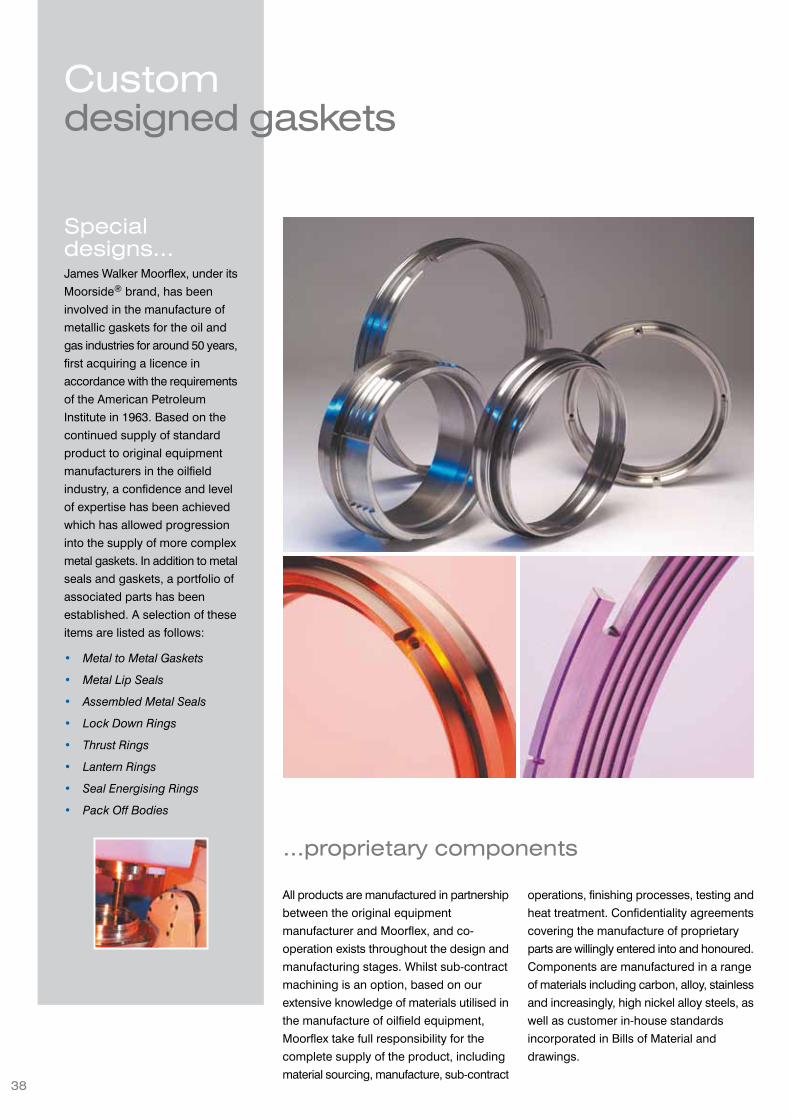
38
Specialdesigns...James Walker Moorflex, under its
Moorside® brand, has been
involved in the manufacture of
metallic gaskets for the oil and
gas industries for around 50 years,
first acquiring a licence in
accordance with the requirements
of the American Petroleum
Institute in 1963. Based on the
continued supply of standard
product to original equipment
manufacturers in the oilfield
industry, a confidence and level
of expertise has been achieved
which has allowed progression
into the supply of more complex
metal gaskets. In addition to metal
seals and gaskets, a portfolio of
associated parts has been
established. A selection of these
items are listed as follows:
• Metal to Metal Gaskets
• Metal Lip Seals
• Assembled Metal Seals
• Lock Down Rings
• Thrust Rings
• Lantern Rings
• Seal Energising Rings
• Pack Off Bodies
Customdesigned gaskets
...proprietary components
All products are manufactured in partnership
between the original equipment
manufacturer and Moorflex, and co-
operation exists throughout the design and
manufacturing stages. Whilst sub-contract
machining is an option, based on our
extensive knowledge of materials utilised in
the manufacture of oilfield equipment,
Moorflex take full responsibility for the
complete supply of the product, including
material sourcing, manufacture, sub-contract
operations, finishing processes, testing and
heat treatment. Confidentiality agreements
covering the manufacture of proprietary
parts are willingly entered into and honoured.
Components are manufactured in a range
of materials including carbon, alloy, stainless
and increasingly, high nickel alloy steels, as
well as customer in-house standards
incorporated in Bills of Material and
drawings.
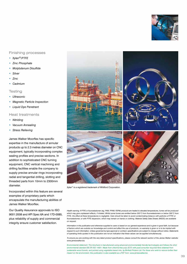
39
Finishing processes• Xylan®/PTFE
• Zinc Phosphate
• Molybdenum Disulfide
• Silver
• Zinc
• Cadmium
Testing• Ultrasonic
• Magnetic Particle Inspection
• Liquid Dye Penetrant
Heat treatments• Nitriding
• Vacuum Annealing
• Stress Relieving
James Walker Moorflex has specific
expertise in the manufacture of annular
products up to 2.3 metres diameter on CNC
equipment, typically incorporating complex
sealing profiles and precise sections. In
addition to sophisticated CNC turning
equipment, CNC vertical machining and
drilling facilities enable the company to
supply precise annular rings incorporating
radial and tangential drilling, slotting and
threaded parts from 10mm to 2300mm
diameter.
Incorporated within this feature are several
examples of proprietary parts which
encapsulate the manufacturing abilities of
James Walker Moorflex.
Our Quality Assurance approvals to ISO
9001:2008 and API Spec 6A and 17D-0085,
plus reliability of supply and commercial
integrity ensure customer satisfaction.
Health warning: If PTFE or fluoroelastomer (eg, FKM, FFKM, FEPM) products are heated to elevated temperatures, fumes will be producedwhich may give unpleasant effects, if inhaled. Whilst some fumes are emitted below 250°C from fluoroelastomers or below 300°C fromPTFE, the effect at these temperatures is negligible. Care should be taken to avoid contaminating tobacco with particles of PTFE orfluoroelastomer, or with PTFE dispersion, which may remain on hands or clothing. Material Safety Data Sheets (MSDS) are availableon request.
Information in this publication and otherwise supplied to users is based on our general experience and is given in good faith, but becauseof factors which are outside our knowledge and control and affect the use of products, no warranty is given or is to be implied withrespect to such information. Unless governed by type approval or contract, specifications are subject to change without notice. Statementsof operating limits quoted in this publication are not an indication that these values can be applied simultaneously.
To ensure you are working with the very latest product specifications, please consult the relevant section of the James Walker website:www.jameswalker.biz.
Environmental statement: This brochure is manufactured using advanced environmentally friendly technologies and follows the strictenvironmental standard BS EN ISO 14001. Made from chlorine-free pulp (ECF) with post-consumer recycled fibre obtained fromsustainable wood forests, and printed using vegetable-based inks, by Binfield Printers Ltd. For those who wish to reduce further theirimpact on the environment, this publication is also available as a PDF from: www.jameswalker.biz.
Xylan® is a registered trademark of Whitford Corporation.

LICENSED UNDERAPI Spec. 6A-0038
API 17D-0085
James Walker Asia PacificTel: +65 6777 9896Fax: +65 6777 6102Email: [email protected]
James Walker AustraliaTel: +61 (0)2 9721 9500Fax: +61 (0)2 9721 9580Email: [email protected]
James Walker Benelux(Belgium)Tel: +32 3 820 7900Fax: +32 3 828 5484Email: [email protected](Netherlands)Tel: +31 (0)186 633111Fax: +31 (0)186 633110Email: [email protected]
James Walker BrasilTel: +55 11 4392 7360Fax: +55 11 4392 5976Email: [email protected]
James Walker ChinaTel: +86 21 6876 9351Fax: +86 21 6876 9352Email: [email protected]
James Walker DeutschlandTel: +49 (0)40 386 0810Fax: +49 (0)40 389 3230Email: [email protected]
James Walker FranceTel: +33 (0)437 497 480Fax: +33 (0)437 497 483Email: [email protected]
James Walker IbericaTel: +34 94 447 0099Fax: +34 94 447 1077Email: [email protected]
James Walker Inmarco (India)Tel: +91 (0)22 4080 8080Fax: +91 (0)22 2859 6220Email: [email protected]
James Walker IrelandTel: +353 (0)21 432 3626Fax: +353 (0)21 432 3623Email: [email protected]
James Walker ItalianaTel: +39 02 257 8308Fax: +39 02 263 00487Email: [email protected]
James Walker Mfg (USA)Tel: +1 708 754 4020Fax: +1 708 754 4058Email: [email protected]
James Walker New ZealandTel: +64 (0)9 272 1599Fax: +64 (0)9 272 3061Email: [email protected]
James Walker NorgeTel: +47 22 706800Fax: +47 22 706801Email: [email protected]
James Walker Oil & Gas (USA)Tel: +1 281 875 0002Fax: +1 281 875 0188Email: [email protected]
James Walker South AfricaTel: +27 (0)31 304 0770Fax: +27 (0)31 304 0791Email: [email protected]
James Walker UKTel: +44 (0)1270 536000Fax: +44 (0)1270 536100Email: [email protected]
James Walker worldwide support & distribution
Registered office: Lion House, Oriental Road, Woking, Surrey GU22 8AP, United Kingdom. Reg No: 575005 England© James Walker 2012
James Walker Moorflex LimitedJohn Escritt RoadBingleyWest Yorkshire BD16 2BS, UKTel: +44 (0) 1274 562211Fax: +44 (0) 1274 566623Email:[email protected]
BP4462 1012/2mPIIL2877990
Certificate No. Q05429BS EN ISO 9001:2008