Gas Turbines Summary - Aerostudents · Gas Turbines Summary 1. Basics of gas turbines ... the ideal...
27
Gas Turbines Summary 1. Basics of gas turbines In this first chapter, we’re going to look at the basics of gas turbines. What are they? When were they developed? How do they work? And how do we perform basic calculations? 1.1 Introduction to gas turbines This is where our journey into the world of gas turbines takes off. And we start with a very important question: what is a gas turbine? 1.1.1 What is a gas turbine? A gas turbine is a machine delivering mechanical power or thrust. It does this using a gaseous working fluid. The mechanical power generated can be used by, for example, an industrial device. The outgoing gaseous fluid can be used to generate thrust. In the gas turbine, there is a continuous flow of the working fluid. This working fluid is initially compressed in the compressor. It is then heated in the combustion chamber. Finally, it goes through the turbine. The turbine converts the energy of the gas into mechanical work. Part of this work is used to drive the compressor. The remaining part is known as the net work of the gas turbine. 1.1.2 History of gas turbines We can distinguish two important types of gas turbines. There are industrial gas turbines and there are jet engine gas turbines. Both types of gas turbines have a short but interesting history. Industrial gas turbines were developed rather slowly. This was because, to use a gas turbine, a high initial compression is necessary. This rather troubled early engineers. Due to this, the first working gas turbine was only made in 1905 by the Frenchman Rateau. The first gas turbine for power generation became operational in 1939 in Switzerland. It was developed by the company Brown Boveri. Back then, gas turbines had a rather low thermal efficiency. But they were still useful. This was because they could start up rather quickly. They were therefore used to provide power at peak loads in the electricity network. In the 1980’s, natural gas made its breakthrough as fuel. Since then, gas turbines have increased in popularity. The first time a gas turbine was considered as a jet engine, was in 1929 by the Englishman Frank Whittle. However, he had trouble finding funds. The first actual jet aircraft was build by the German Von Ohain in 1939. After world war 2, the gas turbine developed rapidly. New high-temperature materials, new cooling techniques and research in aerodynamics strongly improved the efficiency of the jet engine. It therefore soon became the primary choice for many applications. Currently, there are several companies producing gas turbines. The biggest producer of both industrial gas turbines and jet engines is General Electric (GE) from the USA. Rolls Royce and Pratt & Whitney are also important manufacturers of jet engines. 1
Transcript of Gas Turbines Summary - Aerostudents · Gas Turbines Summary 1. Basics of gas turbines ... the ideal...

Gas Turbines Summary
1. Basics of gas turbines
In this first chapter, we’re going to look at the basics of gas turbines. What are they? When were theydeveloped? How do they work? And how do we perform basic calculations?
1.1 Introduction to gas turbines
This is where our journey into the world of gas turbines takes off. And we start with a very importantquestion: what is a gas turbine?
1.1.1 What is a gas turbine?
A gas turbine is a machine delivering mechanical power or thrust. It does this using a gaseous workingfluid. The mechanical power generated can be used by, for example, an industrial device. The outgoinggaseous fluid can be used to generate thrust.
In the gas turbine, there is a continuous flow of the working fluid. This working fluid is initially compressedin the compressor. It is then heated in the combustion chamber. Finally, it goes through the turbine.The turbine converts the energy of the gas into mechanical work. Part of this work is used to drive thecompressor. The remaining part is known as the net work of the gas turbine.
1.1.2 History of gas turbines
We can distinguish two important types of gas turbines. There are industrial gas turbines and thereare jet engine gas turbines. Both types of gas turbines have a short but interesting history.
Industrial gas turbines were developed rather slowly. This was because, to use a gas turbine, a high initialcompression is necessary. This rather troubled early engineers. Due to this, the first working gas turbinewas only made in 1905 by the Frenchman Rateau. The first gas turbine for power generation becameoperational in 1939 in Switzerland. It was developed by the company Brown Boveri.
Back then, gas turbines had a rather low thermal efficiency. But they were still useful. This was becausethey could start up rather quickly. They were therefore used to provide power at peak loads in theelectricity network. In the 1980’s, natural gas made its breakthrough as fuel. Since then, gas turbineshave increased in popularity.
The first time a gas turbine was considered as a jet engine, was in 1929 by the Englishman FrankWhittle. However, he had trouble finding funds. The first actual jet aircraft was build by the GermanVon Ohain in 1939. After world war 2, the gas turbine developed rapidly. New high-temperaturematerials, new cooling techniques and research in aerodynamics strongly improved the efficiency of thejet engine. It therefore soon became the primary choice for many applications.
Currently, there are several companies producing gas turbines. The biggest producer of both industrialgas turbines and jet engines is General Electric (GE) from the USA. Rolls Royce and Pratt &Whitney are also important manufacturers of jet engines.
1

1.1.3 Gas turbine topics
When designing a gas turbine, you need to be schooled in various topics. To define the compressor andthe turbine, you need to use aerodynamics. To get an efficient combustion, knowledge on thermody-namics is required. And finally, to make sure the engine survives the big temperature differences andhigh forces, you must be familiar with material sciences.
Gas turbines come in various sizes and types. Which kind of gas turbine to use depends on a lot ofcriteria. These criteria include the required power output, the bounds on the volume and weight ofthe turbine, the operating profile, the fuel type, and many more. Industrial gas turbines can delivera power from 200kW to 240MW . Similarly, jet engines can deliver thrust from 40N to 400kN .
1.2 The ideal gas turbine cycle
To start examing a gas turbine in detail, we make a few simplifications. By doing this, we wind up withthe ideal gas turbine. How do we analyze such a turbine?
1.2.1 Examining the cycle
Let’s examine the thermodynamic process in an ideal gas turbine. The cycle that is present is known asthe Joule-Brayton cycle. This cycle consists of five important points.
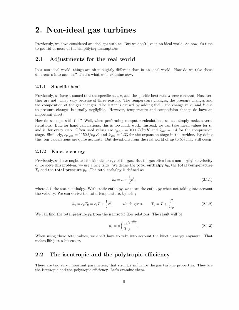
We start at position 1. After the gas has passed through the inlet, we are at position 2. The inlet doesn’tdo much special, so T1 = T2 and p1 = p2. (Since the properties in points 1 and 2 are equal, point 1is usually ignored.) The gas then passes through the compressor. We assume that the compression isperformed isentropically. So, s2 = s3. The gas is then heated in the combustor. (Point 4.) This is doneisobarically (at constant pressure). So, p3 = p4. Finally, the gas is expanded in the turbine. (Point 5.)This is again done isentropically. So, s4 = s5. The whole process is visualized in the enthalpy-entropydiagram shown in figure 1.1.
Figure 1.1: The enthalpy-entropy diagram for an ideal cycle.
We can make a distinction between open and closed cycles. In an open cycle, atmospheric air is used.The exhaust gas is released back into the atmosphere. This implies that p5 = p1 = patm. In a closedcycle, the same working fluid is circulated through the engine. After point 5, it passes through a cooler,before it again arrives at point 1. Since the cooling is performed isobarically, we again have p5 = p1.
When examining the gas turbine cycle, we do make a few assumptions. We assume that the workingfluid is a perfect gas with constant specific heats cp and cv. Also, the specific heat ratio k (sometimesalso denoted by γ) is constant. We also assume that the kinetic/potential energy of the working fluid
2

does not vary along the gas turbine. Finally, pressure losses, mechanical losses and other kinds of lossesare ignored.
1.2.2 The steps of the cycle
Let’s examine the various steps in the gas turbine cycle. During step 2 − 3, the compressor requires acertain compressor power W2−3. During step 3 − 4, a certain amount of heat input Q3−4 is added.And, during step 5 − 2, a certain amount of waste heat Q5−2 is discarded. These quantities can befound using
W2−3 = mcp (T3 − T2) , Q3−4 = mcp (T4 − T3) and Q5−2 = mcp (T5 − T2) . (1.2.1)
Here, m denotes the mass flow through the turbine. Now let’s examine step 4− 5. We can split this stepup into two parts. We do this, by creating an imaginary point g between points 4 and 5. This point issuch that W4−g = W2−3. In other words, the power produced in step 4− g generates the power neededby the compressor. (W4−g is called the turbine power). The remaining power is called the gas power,and is denoted by Wg−5 = Wgg. Both W4−g and Wg−5 are given by
Q4−g = mcp (T4 − Tg) and Qg−5 = mcp (Tg − T5) . (1.2.2)
1.2.3 Performing calculations
Now let’s try to make some calculations. We know that steps 2 − 3 and steps 4 − 5 are performedisentropically. Also, p2 = p5 and p3 = p4. This implies that
ε =p3
p2=
p4
p5=(
T3
T2
) kk−1
=(
T4
T5
) kk−1
, (1.2.3)
where ε is the pressure ratio. Now let’s find a relation for Tg. Since W4−g = W2−3, we must have
Tg = T4 − T3 + T2 = T4 − T2
(ε
k−1k − 1
). (1.2.4)
The important specific gas power Ws,gg is now given by
Ws,gg =Wgg
m= cp (Tg − T5) = cpT4
(1− 1
εk−1
k
)− cpT2
(ε
k−1k − 1
). (1.2.5)
Having a high specific gas power is positive. This is because, to get the same amount of power, we needless mass flow. Our gas turbine can thus be smaller.
1.2.4 The efficiency of the cycle
Based on the equation we just derived, we can find the thermodynamic efficiency ηth of the gasturbine cycle. This rather important parameter is given by
ηth =Euseful
Ein=
Ws,gg
Qs,3−4=
Tg − T5
T4 − T3= 1− T2
T3= 1− 1
εk−1
k
. (1.2.6)
So the efficiency of the cycle greatly depends on the pressure ratio ε. To get an efficient cycle, the pressureratio should be as high as possible.
3

1.2.5 The optimum pressure ratio
Let’s suppose we don’t want a maximum efficiency. Instead, we want to maximize the power Ws,gg.The corresponding pressure ratio ε is called the optimum pressure ratio εopt. To find it, we can setdWs,gg/dε = 0. From this, we can derive that, at these optimum conditions, we have
T3 = T5 =√
T2T4. (1.2.7)
It also follows that the optimum pressure ratio itself is given by
εopt =(
T3
T2
) kk−1
=(
T4
T2
) k2(k−1)
. (1.2.8)
The corresponding values of Ws,gg and η are given by
Ws,ggmax
cpT2=
(√T4
T2− 1
)2
and η = 1−√
T2
T4. (1.2.9)
Note that we have used a non-dimensional version of the specific gas power Ws,gg.
1.3 Enhancing the cycle
There are various tricks, which we can use to enhance the gas turbine cycle. We will examine the threemost important ones.
1.3.1 Heat exchange
The first enhancement we look at the heat exchanger (also known as a recuperator). Let’s supposewe’re applying a heat exchanger. After the gas exits the turbine (point 5), it is brought to this heatexchanger. The heat of the exhaust gas is then used, to warm up the gas entering the combustor (point3). Let’s call the point between the heat exchanger and the combustion chamber point 3.5.
It is important to note that a heat exchanger can only be used if T5 > T3. (Heat only flows from warmerto colder gasses.) And we only have T5 > T3 if ε < εopt. So a heat exchanger is nice for turbines withlow pressure ratios.
Now let’s examine the effects of a heat exchanger. The gas entering the combustor (at point 3.5) isalready heated up a bit. So the combustor needs to add less heat. The heat input Qs,3−4 is thus reduced,increasing the efficiency. In an ideal case, we have T3.5 = T5. In this case, the heat input is given by
Qs,3−4 = cp (T4 − T3.5) = cp (T4 − T5) = cpT4
(1− 1
εk−1
k
). (1.3.1)
The thermodynamic efficiency of the cycle is now given by
ηth =Ws,gg
Qs,3−4=
cpT4
(1− 1
εk−1
k
)− cpT2
(ε
k−1k − 1
)cpT4
(1− 1
εk−1
k
) = 1− T2
T4ε
k−1k . (1.3.2)
In this case, the efficiency increases for decreasing temperature ratios. This is contrary to the case withoutheat exchange. There is a simple reason for this: The lower the pressure ratio, the more heat can beexchanged, and the more the efficiency can be improved by this heat exchange.
4

1.3.2 Intercooling
We can also try to increase the specific gas power Ws,gg. One way to do this, is by making sure thecompressor requires less power. This is where the intercooler comes in.
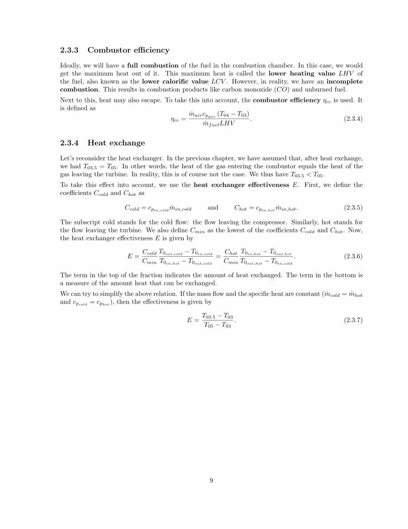
Let’s suppose we’re using an intercooler in the compressor. First, the compressor compresses the gas a bit(point 2.3). The applied pressure ratio is ε1 = p2.3/p2. Then, the gas is cooled by the intercooler (point2.5). (This is usually done such that T2.5 = T2. Intercooling is also performed isobarically, so p2.3 = p2.5.)Finally, the gas is compressed again, until we’re at point 3. The applied pressure ratio during this step isε2 = p3/p2.5. The total applied pressure ratio is εtot = ε1ε2 = p3/p2. The entire process of intercoolinghas been visualized in figure 1.2 (left).
Figure 1.2: The enthalpy-entropy diagram for intercooling (left) and reheating (right).
Thanks to the intercooler, the specific work needed by the compressor has been reduced to
Ws,2−3 = Ws,2−2.3 + Ws,2.5−3 = cp (T2.3 − T2) + cp (T3 − T2.5) . (1.3.3)
The specific gas power Ws,gg has increased by the same amount. The increase in specific gas powerstrongly depends on the pressure ratios ε1 and ε2. It can be shown that, to maximize Ws,gg, we shouldhave
ε1 = ε2 =√
εtot. (1.3.4)
Intercooling may look promising, but it does have one big disadvantage. The combustor needs to domore work. It also needs to provide the heat that was taken by the intercooler. (This is because T3
has decreased.) So, while Ws,gg increases by a bit, Qs,3−4 increases by quite a bit more. Intercoolingtherefore increases the work output, at the cost of efficiency.
1.3.3 Reheating
An idea similar to intercooling is reheating. However, reheating is applied in the turbine. Reheatingincreases the work done by the turbine. A well-known example of applying reheating is the afterburnerin an aircraft.
From point 4, we start by expanding the gas in the turbine. We soon reach point 4.3. (Again, wedefine ε1 = p4/p4.3.) The gas is then reheated, until point 4.5 is reached. (This is done isobarically, sop4.3 = p4.5.) From this point, the gas is again expanded in a turbine, until points g and 5 are reached.We now have ε2 = p4.5/p5 and εtot = ε1ε2 = p4/p5. The entire process of reheating has been visualizedin figure 1.2 (right).
As was said before, reheating increases the work done by the turbine. Let’s suppose that T4 = T4.5. Inthis case, the increase in turbine work is at a maximum if ε1 = ε2 =
√εtot, just like in the case of the
intercooler. Reheating also has the same downside as intercooling. Although the work increases, moreheat needs to be added. So the efficiency decreases.
5
2. Non-ideal gas turbines
Previously, we have considered an ideal gas turbine. But we don’t live in an ideal world. So now it’s timeto get rid of most of the simplifying assumptions.
2.1 Adjustments for the real world
In a non-ideal world, things are often slightly different than in an ideal world. How do we take thosedifferences into account? That’s what we’ll examine now.
2.1.1 Specific heat
Previously, we have assumed that the specific heat cp and the specific heat ratio k were constant. However,they are not. They vary because of three reasons. The temperature changes, the pressure changes andthe composition of the gas changes. The latter is caused by adding fuel. The change in cp and k dueto pressure changes is usually negligible. However, temperature and composition change do have animportant effect.
How do we cope with this? Well, when performing computer calculations, we can simply make severaliterations. But, for hand calculations, this is too much work. Instead, we can take mean values for cp
and k, for every step. Often used values are cp,air = 1000J/kg K and kair = 1.4 for the compressionstage. Similarly, cp,gas = 1150J/kg K and kgas = 1.33 for the expansion stage in the turbine. By doingthis, our calculations are quite accurate. But deviations from the real world of up to 5% may still occur.
2.1.2 Kinetic energy
Previously, we have neglected the kinetic energy of the gas. But the gas often has a non-negligible velocityc. To solve this problem, we use a nice trick. We define the total enthalpy h0, the total temperatureT0 and the total pressure p0. The total enthalpy is defined as
h0 = h +12c2, (2.1.1)
where h is the static enthalpy. With static enthalpy, we mean the enthalpy when not taking into accountthe velocity. We can derive the total temperature, by using
h0 = cpT0 = cpT +12c2, which gives T0 = T +
c2
2cp. (2.1.2)
We can find the total pressure p0 from the isentropic flow relations. The result will be
p0 = p
(T0
T
) kk−1
. (2.1.3)
When using these total values, we don’t have to take into account the kinetic energy anymore. Thatmakes life just a bit easier.
2.2 The isentropic and the polytropic efficiency
There are two very important parameters, that strongly influence the gas turbine properties. They arethe isentropic and the polytropic efficiency. Let’s examine them.
6

2.2.1 Isentropic efficiency
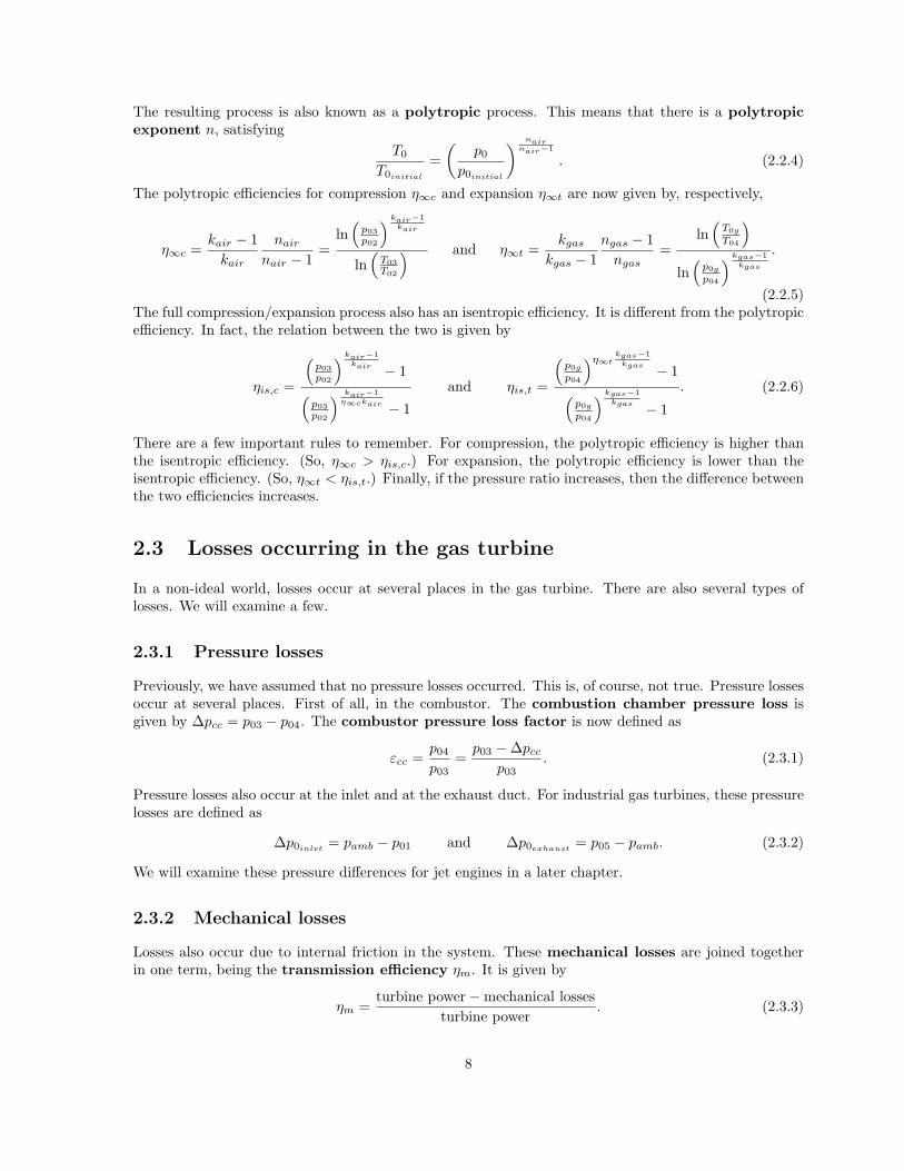
Let’s examine the compressor and the turbine. In reality, they don’t perform their work isentropically.To see what does happen, we examine the compressor. In the compressor, the gas is compressed. In anideal (isentropic) case, the enthalpy would rise from h02 to h03s. However, in reality, it rises from h02 toh03, which is a bigger increase. Similarly, in an ideal (isentropic) turbine, the enthalpy would decreasefrom h04 to h0gs. However, in reality, it decreases from h04 to h0g, which is a smaller decrease. Boththese changes are visualized in figure 2.1.
Figure 2.1: The enthalpy-entropy diagram for a non-ideal cycle.
This effect can be expressed in the isentropic efficiency. The efficiencies for compression and expansionare, respectively, given by
ηis,c =h03s − h02
h03 − h02=
T03s − T02
T03 − T02and ηis,t =
h04 − h0g
h04 − h0gs=
T04s − T0g
T04 − T0gs. (2.2.1)
You may have trouble remembering which difference goes on top of the fraction, and which one goesbelow. In that case, just remember that we always have ηis ≤ 1.
By using the isentropic relations, we can rewrite the above equations. We then find that
ηis,c =
(p03p02
) kair−1kair − 1
T03T02−1
and ηis,t =T0g
T04−1(p0g
p04
) kgas−1kgas − 1
. (2.2.2)
The specific work received by the compressor, and delivered by the turbine, is now given by
Ws,c =cpair
T02
ηis,c
(p03
p02
) kair−1kair
− 1
and Ws,t = cpgasT04ηis,t
(p0g
p04
) kgas−1kgas
− 1
. (2.2.3)
Note that, through the definition of p0g, these two quantities must be equal to each other. (That is, aslong as the mass flow doesn’t change, and there are no additional losses when transmitting the work.)
2.2.2 Polytropic efficiency
Let’s examine a compressor with a varying pressure ratio. In this case, it turns out that also the isentropicefficiency varies. That makes it difficult to work with.
To solve this problem, we divide the compression into an infinite number of small steps. All these infinitelysmall steps have the same isentropic efficiency. This efficiency is known as the polytropic efficiency.
7
The resulting process is also known as a polytropic process. This means that there is a polytropicexponent n, satisfying
T0
T0initial
=(
p0
p0initial
) nairnair−1
. (2.2.4)
The polytropic efficiencies for compression η∞c and expansion η∞t are now given by, respectively,
η∞c =kair − 1
kair
nair
nair − 1=
ln(
p03p02
) kair−1kair
ln(
T03T02
) and η∞t =kgas
kgas − 1ngas − 1
ngas=
ln(
T0g
T04
)ln(
p0g
p04
) kgas−1kgas
.
(2.2.5)The full compression/expansion process also has an isentropic efficiency. It is different from the polytropicefficiency. In fact, the relation between the two is given by
ηis,c =
(p03p02
) kair−1kair − 1(
p03p02
) kair−1η∞ckair − 1
and ηis,t =
(p0g
p04
)η∞tkgas−1
kgas − 1(p0g
p04
) kgas−1kgas − 1
. (2.2.6)
There are a few important rules to remember. For compression, the polytropic efficiency is higher thanthe isentropic efficiency. (So, η∞c > ηis,c.) For expansion, the polytropic efficiency is lower than theisentropic efficiency. (So, η∞t < ηis,t.) Finally, if the pressure ratio increases, then the difference betweenthe two efficiencies increases.
2.3 Losses occurring in the gas turbine
In a non-ideal world, losses occur at several places in the gas turbine. There are also several types oflosses. We will examine a few.
2.3.1 Pressure losses
Previously, we have assumed that no pressure losses occurred. This is, of course, not true. Pressure lossesoccur at several places. First of all, in the combustor. The combustion chamber pressure loss isgiven by ∆pcc = p03 − p04. The combustor pressure loss factor is now defined as
εcc =p04
p03=
p03 −∆pcc
p03. (2.3.1)
Pressure losses also occur at the inlet and at the exhaust duct. For industrial gas turbines, these pressurelosses are defined as
∆p0inlet= pamb − p01 and ∆p0exhaust
= p05 − pamb. (2.3.2)
We will examine these pressure differences for jet engines in a later chapter.
2.3.2 Mechanical losses
Losses also occur due to internal friction in the system. These mechanical losses are joined togetherin one term, being the transmission efficiency ηm. It is given by
ηm =turbine power−mechanical losses
turbine power. (2.3.3)
8
2.3.3 Combustor efficiency
Ideally, we will have a full combustion of the fuel in the combustion chamber. In this case, we wouldget the maximum heat out of it. This maximum heat is called the lower heating value LHV ofthe fuel, also known as the lower calorific value LCV . However, in reality, we have an incompletecombustion. This results in combustion products like carbon monoxide (CO) and unburned fuel.
Next to this, heat may also escape. To take this into account, the combustor efficiency ηcc is used. Itis defined as
ηcc =maircpgas
(T04 − T03)mfuelLHV
. (2.3.4)
2.3.4 Heat exchange
Let’s reconsider the heat exchanger. In the previous chapter, we have assumed that, after heat exchange,we had T03.5 = T05. In other words, the heat of the gas entering the combustor equals the heat of thegas leaving the turbine. In reality, this is of course not the case. We thus have T03.5 < T05.
To take this effect into account, we use the heat exchanger effectiveness E. First, we define thecoefficients Ccold and Chot as
Ccold = cpin,coldmin,cold and Chot = cpin,hot
min,hot. (2.3.5)
The subscript cold stands for the cold flow: the flow leaving the compressor. Similarly, hot stands forthe flow leaving the turbine. We also define Cmin as the lowest of the coefficients Ccold and Chot. Now,the heat exchanger effectiveness E is given by
E =Ccold
Cmin
T0out,cold− T0in,cold
T0in,hot− T0out,cold
=Chot
Cmin
T0in,hot− T0out,hot
T0out,hot− T0in,cold
. (2.3.6)
The term in the top of the fraction indicates the amount of heat exchanged. The term in the bottom isa measure of the amount heat that can be exchanged.
We can try to simplify the above relation. If the mass flow and the specific heat are constant (mcold = mhot
and cpcold= cphot
), then the effectiveness is given by
E =T03.5 − T03
T05 − T03. (2.3.7)
9

3. Gas turbine types
Gas turbines can be used for many purposes. They can be used to deliver power, heat or thrust. Therefore,different gas turbine types exist. In this chapter, we will examine a few. First, we examine shaft powergas turbines. Then, we examine jet engine gas turbines.
3.1 Shaft power gas turbines
A shaft power gas turbine is a gas turbine whose goal is mainly to deliver shaft power. They are oftenalso referred to as turboshaft engines. These gas turbines are often used in industrial applications.Gas turbines used for electricity production are also of this type.
3.1.1 The shaft power
For shaft power gas turbines, the shaft power is very important. It mainly depends on the temperaturedrop in the power turbine (PT). This drop is given by
T0g − T05 = T0gηis,PT
1−(
p05
p0g
) kgas−1kgas
= T0g
1−(
p05
p0g
)η∞,P Tkgas−1
kgas
. (3.1.1)
The efficiencies ηis,PT and η∞,PT are the isentropic and polytropic efficiencies, respectively, of the powerturbine. To apply the above equation, we do need to know the properties of point 5. These propertiescan be derived from the exhaust properties, according to
∆pexh = p05 − pexh and T05 = T0,exh = Texh +c2exh
2cp,gas, (3.1.2)
where cexh is the velocity of the exhaust gas. (By the way, the exhaust point is often also denoted bypoint 9.) Once this data is known, the actual shaft power can be derived. For this, we use the equation
Pshaft = m cp,gas (T0g − T05) ηm,PT , (3.1.3)
with ηm,PT being the mechanical efficiency of the gas turbine.
3.1.2 Other performance parameters
There are also some other parameters that are important for shaft power gas turbines. Of course, thethermal efficiency ηthermal is important. (The thermal efficiency is not the thermodynamic efficiencyηth, introduced in chapter 1. In fact, it is lower. This is because the thermal efficiency also takes intoaccount various types of losses.) This efficiency is given by
ηthermal =Pshaft
mfuel Hfuel, (3.1.4)
where Hfuel is the heating value of the fuel. Other important parameters are the specific fuel con-sumption sfc and the heat rate. The sfc is given by
sfc =mfuel
Pshaft=
1Hfuel ηthermal
. (3.1.5)
The heat rate is given by
heat rate =mfuel Hfuel
Pshaft=
1ηthermal
. (3.1.6)
10

Finally, there is the equivalence ratio λ, also known as the percentage excess air. It is defined as
λ =mair − mst
mst, (3.1.7)
where mst is the air mass flow required for a complete combustion of the fuel. If there is just enough airto burn the fuel, then we have a stoichiometric combustion. In this case, λ = 1. However, usually λis bigger than 1.
3.1.3 Exhaust gas of the shaft power turbine
Shaft power gas turbines usually produce quite some heat. This heat can be used. When applyingcogeneration, we use the heat of the exhaust gas itself. (For example, to produce hot water or steam.)In a combined cycle the heat is used to create additional power. This can be done by expanding theheat in a steam turbine.
The process of creating steam deserves some attention. In this process, heat is exchanged from theexhaust gas to the water/vapor. This is caused by the temperature difference between the exhaust gasand the water/vapor. An important parameter is the temperature difference ∆Tpinch at the so-calledpinch point. This is the point where the water just starts to boil. The entire process, including thepinch point, is also visualized in figure 3.1.
Figure 3.1: Exchanged heat versus temperature diagram for creating steam, using exhaust gas.
We want to minimize the exhaust losses. One way to do that, is to increase the initial exhaust gastemperature. This makes the heat exchange a lot easier. Another option is to split up the process intomultiple steps, where each step has a different pressure. In this case, there will also be multiple pinchpoints.
3.2 Jet engine gas turbines
A jet engine gas turbine is a turbine whose goal is mainly to deliver thrust. This can be done in twoways. We can let the gas turbine accelerate air. We can also let the gas turbine shaft power a propeller.Often, both methods are used. Jet engine gas turbines are mainly used on aircraft.
3.2.1 Finding the thrust
The goal of a jet engine is to produce thrust. The net thrust FN can generally be found using
FN = m (cj − c0) . (3.2.1)
11

c0 indicates the air velocity before the air entered the gas turbine. cj indicates the air velocity after itentered the turbine. (cj − c0) indicates the acceleration of the flow.
We can use the above equation to find the thrust of an actual aircraft. But to do that, we have to definesome control points. Point 0 is infinitely far upstream, point 1 is at the inlet entry, point 8 is at theexhaust exit and point ∞ is infinitely far downstream. To calculate the thrust, we have to use points 0and ∞. The velocity c0 at point zero is simply equal to the airspeed of the aircraft. However, c∞ is veryhard to determine. Luckily, we can use the momentum relation, which states that
m (c∞ − c8) = A (p8 − p∞) = A (p8 − p0) , (3.2.2)
where we have used that p0 = p∞ = patm. If we use this relation, then the net thrust becomes
Fn = m (c∞ − c0) = m (c8 − c0) + A (p8 − p0) . (3.2.3)
The parameter A is the area of the gas turbine at the exhaust. Once the thrust has been found, we canderive the effective jet velocity ceff . It is the velocity that is (theoretically) obtained at point ∞, suchthat the thrust Fn is achieved. It satisfies
Fn = m (ceff − c0) . (3.2.4)
3.2.2 Jet engine power
From the net thrust, we can find the thrust power. It is defined as
Pthrust = Fnc0 = mc0 (ceff − c0) . (3.2.5)
This is the ‘useful’ power of the aircraft. We can also look at the change in kinetic energy of the airpassing through our jet engine. If we do that, then we find the propulsion power Pprop. This can beseen as the ‘input’ power. It is defined as
Pprop =12m(c2eff − c2
0
). (3.2.6)
The difference between the propulsion power and the thrust power is known as the loss power. It isdefined as
Ploss = Pprop − Pthrust =12m (ceff − c0)
2. (3.2.7)
3.2.3 Efficiencies
From the propulsion power and the thrust power, we can derive the propulsive efficiency ηprop, alsoknown as the Froude efficiency. It is given by
ηprop =Pthrust
Pprop=
21 + ceff
c0
. (3.2.8)
To increase the propulsive efficiency, we should keep ceff as low as possible. So it’s better to accelerate alot of air by a small velocity increment, than a bit of air by a big velocity increment. Now let’s examinethe thermal efficiency ηthermal of the jet engine. It is given by
ηthermal =Pprop
mfuel Hfuel. (3.2.9)
It is a measure of how well the available thermal energy has been used to accelerate air. We can alsolook at the jet generation efficiency ηjet. It is defined as
ηjet =Pprop
Pgg. (3.2.10)
12

This is a measure of how well the energy from the power turbine has been used to accelerate air. Andnow, we can finally define the total efficiency. It is given by
ηtotal =Pthrust
mfuel Hfuel= ηpropηthermal. (3.2.11)
3.2.4 Other important parameters
Next to the efficiencies, there are also quite some other parameters that say something about jet engines.First, there is the specific thrust Fs. It is defined as the ratio between the net thrust and the air intake.So,
Fs =FN
m. (3.2.12)
Second, we have the thrust specific fuel consumption TSFC, which is the ratio between the fuelflow and the thrust. We thus have
TSFC =mfuel
FN=
c0
ηtotal Hfuel. (3.2.13)
3.2.5 Improving the jet engine
We have previously noted that it’s best to give a small velocity increment to a large amount of air.However, jet engines theirselves usually give quite a big acceleration to the air. For this reason, mostcommercial aircraft engines have big propellers, called turbofans. These fans are driven by the shaft ofthe jet engine. And they give, as iss required, a small velocity increment to a large amount of air. Thisair then bypasses (flows around) the jet engine itself.
The relation for the thrust of a turbofan engine is similar to that of a normal jet engine. The onlydifference, is that we need to add things up. So,
FN = mjet (c8 − c0) + Ajet (p8 − p0) + mfan (c8 − c0) + Afan (p8 − p0) . (3.2.14)
The rest of the equations also change in a similar way.
13

4. Combustion
The combustion chamber is the part where energy is inserted into the gas turbine. In this chapter, we’regoing to examine it in detail.
4.1 The combustion process
First, we will look at the combustion process. What reaction is taking place? And what parametersinfluence this reaction?
4.1.1 The combustion process
The combustor provides the energy input for the gas turbine cycle. It receives air, inserts fuel, mixes thetwo components and then it lets the mixture combust. This process is known as internal combustion.In a gas turbine, it is generally done at constant pressure. (Although small pressure losses are generallypresent.)
An important parameter during combustion is the T04 temperature. It effects the power output andthe thermal efficiency. T04 is generally limited by material properties. The materials must be able towithstand large temperatures and temperature gradients. If not, the gas turbine might fail.
4.1.2 The reaction
Gas turbines mainly use kerosene-type fuels. These fuels consist of hydrocarbons with the chemicalcomposition CxHy. They are mixed with air and then combusted. The ideal reaction is then given by
CxHy +ε (XO2O2 + XN2N2 + XCO2CO2 + XArAr)→ nCO2CO2 +nH2OH2O+nN2N2 +nArAr. (4.1.1)
In this equation, the X’s indicate the composition of air. We thus have
XO2 = 0.2095, XN2 = 0.7808, XCO2 = 0.0003 and XAr= 0.0094. (4.1.2)
The term ε is the number of moles of air necessary for every mole of fuel. It is given by
ε =x + 1
4y
XO2
. (4.1.3)
Finally, the n′s denote the amount of reaction products. We find that we have
nCO2 = x + εXCO2 , nH2O =12y, nN2 = εXN2 and nAr
= εXAr. (4.1.4)
In reality, we don’t have this ideal reaction. In the real world, not all fuel gets combusted. Not all carbonatoms form carbon dioxide CO2. (We will also have carbon monoxide CO.) And there will be variousother reaction products as well. We won’t examine all those reaction products though.
4.1.3 Reaction parameters
When combusting the mixture, the fuel-to-air ratio FAR = mfuel/mair is an important parameter.We know that, to combust 1 mole of fuel, we need ε moles of air. In stoichiometric conditions, there isprecisely enough air to combust all fuel. The stoichiometric fuel-to-air ratio is therefore given by
FARst =(
mfuel
mair
)st
=1ε
MCxHy
Mair=
XO2
x + 14y
MCxHy
Mair. (4.1.5)
14

The symbols MCxHyand Mair denote the molar mass of the fuel and the air, respectively. Similar to
the FAR, we also have the air-to-fuel ratio AFR. This is simply given by AFR = 1/FAR. Since thevalue of the FAR is usually quite small, the AFR might be easier to work with.
Of course, in the real world, the reaction isn’t stoichiometric. In fact, we define the fuel-to-air equiva-lence ratio ϕ as
ϕ =FAR
FARst=
AFRst
AFR=
mfuel
mair
1FARst
. (4.1.6)
If ϕ = 1, then our combustion is performed at stoichiometric conditions. If we have more fuel, then ϕ > 1and we have a fuel-rich mixture. If we have less fuel, then ϕ < 1 and we have a fuel-lean mixture.From ϕ, we can also find the percentage stoichiometric air, defined as
percentage stoichiometric air =100%
ϕ. (4.1.7)
We can also use ϕ to find the percentage excess air λ. We do this according to
λ =1− ϕ
ϕ. (4.1.8)
If λ is positive, then there is plenty of air: we have a fuel-lean mixture.
4.1.4 The heat formed during combustion
We will now examine the heat produced during the combustion. To do this, we will use a conceptcalled absolute enthalpy. The absolute enthalpy doesn’t only take into account the temperature of asubstance. Also the enthalpy of formation plays a role.
Now let’s examine a combustion chamber operating at a constant temperature. So-called reactants,with absolute enthalpy hreact, enter the chamber. Reaction products, with enthalpy hprod, leave thechamber. The heat ∆hc leaving the chamber (called the enthalpy of combustion) is now given by
∆hc = hreact − hprod. (4.1.9)
The unit of ∆hc is Joule per mole of mixture. Usually, we want to know the lower heating value LHVof the fuel. This is the heat produced per kilogram of fuel. To find it, we can use
LHV =∆hc
Mmix
mmix
mfuel, (4.1.10)
where Mmix is the molar mass of the mixture. We can apply these ideas to the combustion process. Ifwe then also make a few simplifying assumptions, then we wind up with
mfuel ηc LHV = mair cp,gas (T04 − T03) . (4.1.11)
The left part of the equation indicates the effective heat input. The right part indicates the result of thisheat input. The parameter ηc is known as the combustion efficiency. We can also rewrite the aboveequation, by making use of the fuel-to-air equivalence ratio. We then get
T04 = T03 +ϕ FARst
cp,gasηc LHV. (4.1.12)
Due to all the approximations, this equation is not very accurate for higher temperatures and equivalenceratios.
Finally, there is the concept of the adiabatic flame temperature. To introduce it, we suppose that weburn the mixture in a closed adiabatic chamber. In this case, no heat leaves the chamber. The absoluteenthalpy thus stays the same (∆hc = 0). However, the temperature T does rise. In fact, it rises from theinitial reactant temperature to the adiabatic flame temperature Tad. So, we find that Tad is definedsuch that
hprod(Tad) = hreact(Treact). (4.1.13)
15

4.2 The layout of the combustion chamber
Designing a combustion chamber is not an easy thing. There are several complicated parts in it. So let’sexamine how a combustion chamber is build up.
4.2.1 The general layout
There are several types of combustion chambers. But virtually all combustion chambers have a diffuser,a casing, a liner, a fuel injector and a cooling arrangement. The entire general layout is visualized infigure 4.1.
Figure 4.1: The layout of the combustion chamber.
4.2.2 The diffuser
The gas entering the combustion chamber usually has quite a high velocity. This velocity will be respon-sible for a pressure drop. (This pressure drop is called the cold loss.) Also, the flame in the combustionchamber can not survive if the air has a high velocity. Therefore, the airflow needs to be slowed down.And this is exactly the task of the diffuser.
Diffusers can be distinguished by how quickly they decrease the velocity. In the aerodynamic diffuser,the flow is slowed down gradually, while in the dump diffuser, it is slowed down quickly. The dumpdiffuser has more losses, but is also smaller. It is therefore mainly used in aircraft jet engines.
4.2.3 The casing and the liner
After the airflow has passed the diffuser, it is split up by the liner. One part of the airflow goes throughthe region between the liner and the casing. This region is called the annulus. Another part of theairflow enters the mixing chamber, where fuel is injected.
There are several reasons for splitting up the flow. First, the air-to-fuel should have the right value. If itis too high, the mixture will not ignite. Also, the velocity of the flow leaving the diffuser is still too high.The part of the flow that will be ignited has to be slowed down even further.
The liner is divided into three sections. There is a primary zone (PZ), a secondary/intermediatezone (SZ/IZ) and a tertiary/dilution zone (TZ/DZ). The main function of the PZ is to provideenough time for the fuel to mix and combust. The goal of the SZ is to provide enough time to achieve fullcombustion. This significantly reduces bad reaction products like carbon monoxide CO and unburned
16

hydrocarbons (UHC). Finally, the goal of the DZ is to reduce the temperature of the outlet stream,such that it is acceptable for the turbine.
4.2.4 The fuel injector
The fuel injector injects the fuel into the flow. It is important that the fuel is vaporized before it entersthe flame zone. Otherwise, it might not combust properly.
To promote vaporization, the fuel should be atomized. This means that the fuel is converted into smalldrops. This increases vaporization rates. To accomplish this, an atomizer is used. To atomize fuel, ithas to be given a high relative velocity, with respect to the airflow. So-called pressure-assist atomizersgive the fuel a high velocity. On the other hand, air blast atomizers inject slow-moving fuel into ahigh-velocity air stream.
4.2.5 Flame stabilization
After the fuel has been injected into the flow, the flow will enter the flame region. It does this with quitea high velocity. To make sure the flame isn’t blown away, flow reversal can be applied in the PZ. Thiscauses the flow to reverse direction. The best way to reverse the flow, is to swirl it. This is done usingswirlers. The two most important types of swirlers are axial swirlers and radial swirlers.
The most important advantage of flow reversal, is that the flow speed varies a lot. So there will be apoint at which the airflow velocity matches the flame speed. (The flame speed is the speed, relative tothe airflow, at which the flame can move.) This is the point where the flame anchors.
4.2.6 Cooling
The liner is exposed to high temperatures, during combustion. It therefore needs to be cooled, using theairflow in the annulus. There are several ways to do this.
In film cooling, stacks of holes are put in the liner. These holes inject air along the inner surface of theliner, prodiving a protective cooling film. A downside is that the liner is not cooled evenly. The best wayto cool the liner evenly, is by using transpiration cooling. Now, the liner wall is constructed from aporous material that allows air to pass through it.
Next to these cooling methods, we can also put metallic tiles onto the inner surface of the liner. Thisprovides some protection. Finally, the airflow passing through the annulus will also automatically providesome convection cooling.
4.2.7 Combustor types
We can distinguish combustors by their shape. Can-type combustors (also known as tubular com-bustors) consist of several cylindrical tubes, placed around the turbine shaft. Each tube has both a linerand a casing. Although these types of turbines are easy to develop, their weight is relatively high.
Another type of combustor is the annular combustor. The annular combustor has a single ring-shapedliner mounted inside a single ring-shaped casing. Due to the low weight, this type is mostly used inaircraft jet engines. A downside is that it’s sensitive to buckling loads.
Finally, we can combine the can-type and the annular combustor. We then get a can-annular combus-tor. We now have several cylindrical liners (like in the tubular combustor) placed in a single ring-shapedcasing (like in an annular combustor).
17

4.3 Unwanted phenomena
Gas turbines don’t just deliver power, without any side-effects. We will now look at the bad sides of thecombustion chamber.
4.3.1 Combustion stability
An important property of a combustion chamber is combustion stability. To have combustion stability,the flame must remain stable at varying fuel mixtures, inlet temperatures, turbulence levels, flow speedsand so on. If it doesn’t, things can go wrong.
To simplify the idea of combustion stability, we usually only consider the mixture. The combustionstability now depends on the range of the FAR at which the flame remains stable. If the flame dies dueto too much fuel, we have rich extinction. Similarly, if there is too little fuel, we have weak extinction.
The two limits mainly depend on the mass flow of air mair passing through the combustion chamber.Flames have trouble surviving at high flow velocities. And a high flow velocity is, of course, linked toa high mass flow. So too high flow velocities/mass flows aren’t good. On the other hand, if the flowvelocity is too low, the flame will move upstream. This is called flashback. It’s not very good either.So, we don’t want a low flow velocity either.
4.3.2 Losses
Several losses occur in the combustion chamber. First, there is a heat loss. This has several causes. Heatis being spent on heating up/vaporizing the fuel, and on heating the combustor itself. Another cause isincomplete combustion. If part of the fuel does not combust, then heat is wasted. To take this intoaccount, we define the factor of complete combustion ηcomplete as
ηcomplete =mreacted
f
minjectedf
=mevaporated
f
minjectedf
mmixedf
mevaporatedf
mreactedf
mmixedf
. (4.3.1)
Luckily, we have ηcomplete ≈ 100% at normal operating conditions.
Next to heat losses, there are also pressure losses. The so-called cold losses are caused by skin frictionand turbulence effects. These are, in turn, caused by the diffuser, the swirler and the liner. So, we have
(∆p03−04)cold = (∆p)diffuser + (∆p)swirler + (∆p)liner . (4.3.2)
The hot losses are caused by changes in momentum of the flow. They are caused by temperaturechanges. An estimation of the hot pressure losses is given by
(∆p03−04)hot =12ρ3V3
(T4
T3− 1)
, where V3 =m3
ρ3Acasing. (4.3.3)
4.3.3 Pollutants
Hydrocarbon-fueled gas turbines usually have several unwanted combustion products. The most impor-tant combustion products are H2O, CO2, O2 and N2. These are the so-called products of completecombustion, and make up 99% of the combustion products.
The remainder of the combustion products can be split up into two groups. The group of gaseouspollutants consists of nitrogen oxides NOx, carbon monoxide CO and a variety of unburned
18

hydrocarbons UHCs. The amount of gaseous pollutants is usually given by the emission index (EI).This is defined as
EI =mass of the produced pollutant in g
mass of fuel used in kg. (4.3.4)
The second group of remaining combustion products is called smoke. It mainly consists of soot parti-cles, which are particles with a high amount of carbon in them.
19

5. Compressor and turbines
In this chapter, we will look at the compressor and the turbine. They are both turbomachinery:machines that transfer energy from a rotor to a fluid, or the other way around. The working principle ofthe compressor and the turbine is therefore quite similar.
5.1 Axial compressors
We will mainly look at axial compressors. This is because they are the most used type of compressors.Also, axial compressors work very similar to axial turbines.
5.1.1 Euler’s equation for turbomachinery
Let’s examine a rotor, rotating at a constant angular velocity ω. The initial radius of the rotor is r1,while the final radius is r2. A gas passes through the rotor with a constant velocity c. The rotor causesa moment M on the gas. The power needed by the rotor is thus P = Mω.
It would be nice if we can find an expression for this moment M . For that, we first look at the force Facting on the gas. It is given by
F =d(mc)
dt= mc, (5.1.1)
where we have used the assumption that c stays constant. Only the tangential component Fu contributesto the moment. Every bit of gas contributes to this tangential force. It does this according to
dFu = mdcu, (5.1.2)
where cu is the tangential velocity of the air. Let’s integrate over the entire rotor. We then find that
M =∫ 2
1
dM =∫ 2
1
r dFu = m
∫ 2
1
r dcu = m (cu,2r2 − cu,1r1) . (5.1.3)
The power is now given by
P = Mω = m (cu,2r2 − cu,1r1) ω = m (cu,2u2 − cu,1u1) . (5.1.4)
In this equation, u denotes the speed of the rotor at a certain radius r. We have also used the fact thatω = u1/r1 = u2/r2. The above equation is known as Euler’s equation for turbomachinery.
5.1.2 The axial compressor power
Let’s examine an axial compressor. This compressor has rotors and stators. The rotors are moving.They increase the kinetic energy of the gas. The stators are not moving. They are used to turn thekinetic energy into an increase in pressure.
Let’s examine the velocities of the gas, as it passes through a rotor and a stator. The situation is shownin figure 5.1. At the point we’re examining, the rotor is moving with a velocity u. The velocity of thegas, relative to the rotor, is denoted by v. The angle between the flow velocity c and the shaft axis isdenoted by α. The angle between the rotor blade angle and the shaft axis is denoted by β.
The component of the velocity c in axial direction is denoted by ca. It is assumed to be constant alongthe compressor. There is a relation between ca and u. It is given by
u = ca (tanα1 + tanβ1) = ca (tanα2 + tanβ2) . (5.1.5)
20

Figure 5.1: The velocities of the gas in the axial compressor.
It follows that(tanα1 + tanβ1) = (tanα2 + tanβ2) . (5.1.6)
Let’s try to use Euler’s equation for turbomachinery. We know that u1 = u2 = u. We can also use therelations
cu,1 = ca tanα1 and cu,2 = ca tanα2. (5.1.7)
Finally, we divide Euler’s equation by the mass flow. This gives us the specific power Ws. We thusfind that
Ws = u (cu,2 − cu,2) . (5.1.8)
In reality, this isn’t the compressor power. This is mainly because the axial flow velocity ca varies fordifferent radial distances r. To take this effect into account, we use the work-done factor λ. The powerof the compressor is now given by
P = λmWs. (5.1.9)
Generally, λ becomes small for compressors with multiple stages.
5.1.3 Axial compressor properties
An important effect of the compressor is a rise in the total (stagnation) temperature. In fact, this rise isgiven by
∆T0s =Ws
cp=
λuca
cp(tanα2 − tanα1) . (5.1.10)
If we take into account the isentropic efficiency ηis of the compression stage, then we can also find thepressure ratio. It is given by
ε =(
1 + ηis∆T0s
T01
) γγ−1
=(
1 +ηisλuca (tanα2 − tanα1)
cpT01
) γγ−1
. (5.1.11)
From this, we can also derive the degree of reaction. The degree of reaction Λ states which part of thetotal temperature rise is caused by the rotor. We thus have
Λ =∆T0s,rotor
∆T0s,rotor + ∆T0s,stator. (5.1.12)
It can be shown that, for an axial compressor, we have
Λ =ca
2u(tanβ2 + tanβ1) = 1− ca
2u(tanα1 + tanα2) . (5.1.13)
21
5.1.4 Three-dimensional axial compressors
Previously, we have considered axial compressors as two-dimensional. In reality, they are three-dimensional.The most important effect is that the flow is pushed to the outside of the compressor. This causes apressure gradient, according to
dp
dr= ρ
c2u
r. (5.1.14)
We can combine this equation with the thermodynamic relation
dh = T ds +1ρdp = T ds +
c2u
rdr. (5.1.15)
We should also examine the definition of the total enthalpy. It is given by
h0 = h +12c2 = h +
12(c2u + c2
a
). (5.1.16)
Let’s take the derivative of the last two equations, with respect to r. The entropy usually doesn’t varymuch in radial direction, so we may neglect ds/dr. Combining all data will then give
dh0
dr=
c2u
r+ cu
dcu
dr+ ca
dca
dr. (5.1.17)
This equation is called the vortex energy equation. Usually, we also assume that the total enthalpyh0 and the axial velocity ca don’t vary in radial direction. (So dca/dr = dh0/dr = 0.) In this case, wecan solve for cu. It is given by
cur = constant. (5.1.18)
This condition is known as the free vortex condition. It’s often used, when designing compressors.The necessary twist of the compressor blades can be derived from it.
5.2 Compressor and turbine behaviour
Compressors and turbines often show strange behaviour. Let’s take a look at the kind of phenomena thatmay occur, and how we can analyze them.
5.2.1 The characteristic
The compressor has several important parameters. There are the mass flow m, the initial and finaltemperatures T02 and T03, the initial and final pressures p02 and p03, the shaft speed ω (also denoted asN or Ω), the rotor diameter D, and so on.
Let’s suppose we’ll be working with different kinds of compressors. In this case, it would be nice if wecould compare these parameters in some way. To do that, dimensionless parameters are used. By usingdimensional analysis, we can find that there are four dimensionless parameter groups. They are
m√
RT02
p02D2,
p03
p02,
ωD√RT02
and η. (5.2.1)
These parameter groups are known as the mass flow parameter group, the pressure ratio, the shaftspeed parameter group and the efficiency. The efficiency can be either polytropic or isentropic.(These two efficiencies depend on each other anyway.)
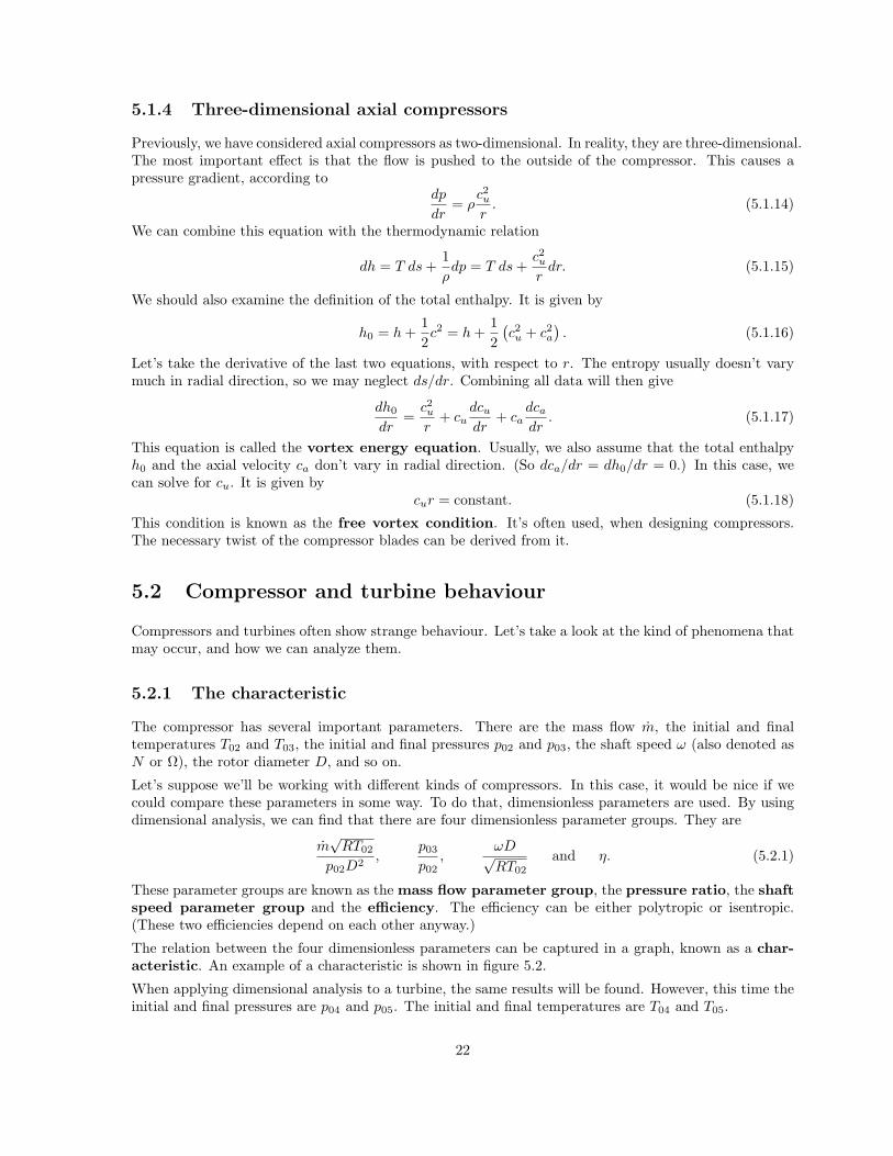
The relation between the four dimensionless parameters can be captured in a graph, known as a char-acteristic. An example of a characteristic is shown in figure 5.2.
When applying dimensional analysis to a turbine, the same results will be found. However, this time theinitial and final pressures are p04 and p05. The initial and final temperatures are T04 and T05.
22
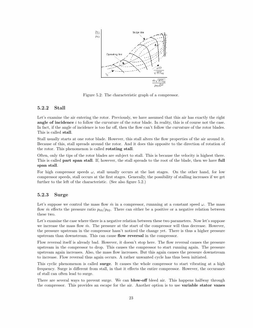
Figure 5.2: The characteristic graph of a compressor.
5.2.2 Stall
Let’s examine the air entering the rotor. Previously, we have assumed that this air has exactly the rightangle of incidence i to follow the curvature of the rotor blade. In reality, this is of course not the case.In fact, if the angle of incidence is too far off, then the flow can’t follow the curvature of the rotor blades.This is called stall.
Stall usually starts at one rotor blade. However, this stall alters the flow properties of the air around it.Because of this, stall spreads around the rotor. And it does this opposite to the direction of rotation ofthe rotor. This phenomenon is called rotating stall.
Often, only the tips of the rotor blades are subject to stall. This is because the velocity is highest there.This is called part span stall. If, however, the stall spreads to the root of the blade, then we have fullspan stall.
For high compressor speeds ω, stall usually occurs at the last stages. On the other hand, for lowcompressor speeds, stall occurs at the first stages. Generally, the possibility of stalling increases if we getfurther to the left of the characteristic. (See also figure 5.2.)
5.2.3 Surge
Let’s suppose we control the mass flow m in a compressor, runnning at a constant speed ω. The massflow m effects the pressure ratio p03/p02. There can either be a positive or a negative relation betweenthese two.
Let’s examine the case where there is a negative relation between these two parameters. Now let’s supposewe increase the mass flow m. The pressure at the start of the compressor will thus decrease. However,the pressure upstream in the compressor hasn’t noticed the change yet. There is thus a higher pressureupstream than downstream. This can cause flow reversal in the compressor.
Flow reversal itself is already bad. However, it doesn’t stop here. The flow reversal causes the pressureupstream in the compressor to drop. This causes the compressor to start running again. The pressureupstream again increases. Also, the mass flow increases. But this again causes the pressure downstreamto increase. Flow reversal thus again occurs. A rather unwanted cycle has thus been initiated.
This cyclic phenomenon is called surge. It causes the whole compressor to start vibrating at a highfrequency. Surge is different from stall, in that it effects the entire compressor. However, the occuranceof stall can often lead to surge.
There are several ways to prevent surge. We can blow-off bleed air. This happens halfway throughthe compressor. This provides an escape for the air. Another option is to use variable stator vanes
23

(VSVs). By adjusting the stator vanes, we try to make sure that we always have the correct angle ofincidence i. Finally, the compressor can also be split up into parts. Every part will then have a differentspeed ω.
Contrary to compressors, turbines aren’t subject to surge. Flow simply never tends to move upstream ina turbine.
5.2.4 Choked flow
Let’s examine the pressure ratio p04/p05 in a turbine. Increasing this pressure ratio usually leads to anincrease in mass flow m. However, after a certain point, the mass flow will not increase further. This iscalled choked flow. It occurs, when the flow reaches supersonic velocities.
Choked flow can also occur at the compressor. If we look at the right side of figure 5.2, we see verticallines. So, when we change the pressure ratio p03/p02 at constant compressor speed ω, then the mass flowremains constant.
24

6. Loads and materials
The parts in a gas turbine are subject to several kinds of loads. To cope with these loads, the rightmaterials need to be used. In this chapter, we’ll take a look at the loads and materials used.
6.1 Loads and failures
We will take a look at the load types that are present in a gas turbine. We also examine how these loadtypes can cause failure.
6.1.1 Load types
A lot of types of loads occur in the gas turbine. Let’s take a look at a few
• Centrifugal loads are caused by high rotational speeds. The centrifugal force is proportional tomω2r.
• Thermal loads are caused by temperature changes. These loads are only present if parts can’texpand freely. This can be caused by two reasons. Either the two connected parts are heateddifferently, or the parts have a different coefficient of thermal expansion (CTE).
• Vibrational loads occur when an object is excited by a frequency close to its natural frequency.We generally want to prevent vibrational loads. Therefore, components need to be designed suchthat their natural frequency isn’t near to a frequency occurring in the gas turbine.
• Pressure loads occur due to pressure differences. They mainly occur in the compressor and theturbine. This causes bending of the blades. To prevent this, the blades are usually made such thatthe pressure loads are cancelled out by the centrifugal loads.
6.1.2 Types of failure
There are many ways in which a part of a gas turbine can fail. Again, we examine a couple of them.
• Static failure (or overload) is quite simple. The present load is bigger than the material strength.To make sure that static failure does not occur, the right material needs to be selected. Specialattention has to be payed to the yield strength and the ultimate strength. These parametersoften depend on the temperature T . Also, a (usually big) safety margin has to be taken intoaccount.
• Fatigue is a failure type caused by a cyclic load. We can make a distinction between High CycleFatigue (HCF) and Low Cycle Fatigue (LCF). In HCF, a lot of cycles (usually over 106) areneeded to cause fatigue failure. Only elastic stresses are present. HCF failure is often caused byvibrations. LCF is fatigue due to inelastic stresses.
An important parameter for fatigue is the number of cycles until failure. This can be derived from aWohler curve. In this curve, the number of cycles until failure is plotted for various stress levels.The Wohler curve generally depends on the temperature.
Fatigue failure is caused by growing cracks. Cracks can be initiated by foreign object damage(FOD), like dirt or birds hitting the gas turbine. After the crack has been initiated, it will grow.The crack growth da/dN is expressed in the increase in crack distance da per cycle dN . Crackgrowth occurs in three stages. First, there is the slow grack growth region, in which the crack
25

growth is low. Second, there is the power law region. In this region, the crack growth increases.It does this according to the Paris law
da
dN= C (∆K)n
, (6.1.1)
where C and n are constants. ∆K is the load factor. The third and last step is final failure, inwhich the growth rate diverges.
• Creep is inelastic deformation, caused by low forces at high temperatures. The magnitude of thecreep rate εcr highly depends on the temperature T . It depends on the stress level σ as well. Thecreep strain εcr shows a similar behaviour as the crack growth. Again, there are three stages.This time, the second stage is characterised by a power law like
εcr = ATnσm. (6.1.2)
• In corrosion, a corrosive medium (like oxygen, nitrogen or sulfur) reacts with the metal surface.Due to this, an embrittled layer is formed, from which large flakes can break away. Corrosiongenerally doesn’t cause failure itself, but it encourages the other failure types.
Different parts are subject to different types of failure. Fatigue mainly occurs in rotating/moving parts,like the compressor and the turbine. Damage caused by thermal degredation is mostly present in partswith high temperatures, like the combustion chamber and the turbine.
6.2 Building the gas turbine
Let’s take a look at how we build a gas turbine. What materials do we select? What coatings do weapply? And how do we make sure that the gas turbine stays in working order?
6.2.1 Materials
First, we look at the compressor blades. They are subjected to high mechanical loads, due to the highrotational speed. We thus want to have materials with a high specific strength σUTS/ρ and a highspecific stiffness E/ρ. Stainless steel, titanium and nickel alloys are suitable for this. Of these three,titanium gives the largest weight savings. Drawbacks are the high cost of titanium and its flammability.
Now we examine the turbine blades. The first stage turbine rotor blades are the most severely loadedcomponents in the gas turbine. We thus want to have a high quality material. It should have a highspecific strength, a high thermal mechanical fatigue resistance, a high creep resistance, sufficient ductility(to sustain FOD) and a reasonable oxidation and corrosion resistance. All these properties need to bemaintained at high temperatures. Although blade-cooling systems limit the temperature as much aspossible, the turbine blades will still get quite hot.
6.2.2 Manufacturing
Manufacturing gas turbine parts can be quite difficult. This especially holds for the turbine blades. Dueto the high-strength materials, forging is not possible. Casting techniques are therefore used. To beprecise, the method of investment casting is used.
Coatings are also often applied. This can be done for different reasons. First of all, coatings protectagainst oxidation/corrosion. A second reason for applying coatings, is for thermal protection. Theseso-called thermal barrier coatings (TBCs) have a low thermal conductivity. They therefore thermallyinsulate the part they’re covering.
26

When applying coatings, either diffusion coating or overlay coating is used. In diffusion coating, achemical reaction is used to put the coating onto the metal part. In overlay coating, the coating is simplysprayed/deposited onto the part.
6.2.3 Design philosophies
Let’s ask ourselves an important question: When do we replace parts? The answer to this questiondepends on the design philosophy we apply.
In the safe-life philosophy, no inspections are applied. The part is simply replaced after it has reachedits life limit. The life limit is determined using Wohler curves. A downside of this method is that partsare often replaced, that do not need replacing yet. Also, components are often found damaged before thelife limit is reached.
In the damage tolerance philosophy, the possibility of cracks/flaws is taken into account. Therefore,regular inspections are performed. These inspections are performed such that cracks are detected beforethey can cause serious harm. However, at the end of the life limit, the parts are replaced, no matter ifdamage has occurred or not.
In the retirement for cause (RFC) philosophy, life extension beyond the life limit is applied. To dothis, risk assessments are used. First, the allowable risk is set. This allowable risk then determines theincrease of the life limit. In the RFC philosophy, it is exactly known how much risks are taken. This isan advantage.
27